JP6491580B2 - Dumping equipment for waste treatment facilities - Google Patents
Dumping equipment for waste treatment facilities Download PDFInfo
- Publication number
- JP6491580B2 JP6491580B2 JP2015184241A JP2015184241A JP6491580B2 JP 6491580 B2 JP6491580 B2 JP 6491580B2 JP 2015184241 A JP2015184241 A JP 2015184241A JP 2015184241 A JP2015184241 A JP 2015184241A JP 6491580 B2 JP6491580 B2 JP 6491580B2
- Authority
- JP
- Japan
- Prior art keywords
- waste
- lid
- opening
- dumping
- damping
- Prior art date
- Legal status (The legal status is an assumption and is not a legal conclusion. Google has not performed a legal analysis and makes no representation as to the accuracy of the status listed.)
- Active
Links
- 239000002699 waste material Substances 0.000 title claims description 307
- 238000013016 damping Methods 0.000 claims description 83
- 230000002093 peripheral effect Effects 0.000 claims description 20
- 238000007790 scraping Methods 0.000 claims description 13
- 239000010813 municipal solid waste Substances 0.000 description 49
- 101150054854 POU1F1 gene Proteins 0.000 description 20
- 239000000463 material Substances 0.000 description 10
- VNWKTOKETHGBQD-UHFFFAOYSA-N methane Chemical compound C VNWKTOKETHGBQD-UHFFFAOYSA-N 0.000 description 10
- 238000007689 inspection Methods 0.000 description 4
- 241000209094 Oryza Species 0.000 description 3
- 235000007164 Oryza sativa Nutrition 0.000 description 3
- 239000004033 plastic Substances 0.000 description 3
- 229920003023 plastic Polymers 0.000 description 3
- 235000009566 rice Nutrition 0.000 description 3
- 239000010902 straw Substances 0.000 description 3
- 239000000126 substance Substances 0.000 description 3
- 239000002023 wood Substances 0.000 description 3
- 241000609240 Ambelania acida Species 0.000 description 2
- 239000002028 Biomass Substances 0.000 description 2
- 240000000111 Saccharum officinarum Species 0.000 description 2
- 235000007201 Saccharum officinarum Nutrition 0.000 description 2
- 238000013459 approach Methods 0.000 description 2
- 239000010905 bagasse Substances 0.000 description 2
- 239000002361 compost Substances 0.000 description 2
- 238000009264 composting Methods 0.000 description 2
- 239000000428 dust Substances 0.000 description 2
- 230000005611 electricity Effects 0.000 description 2
- 238000000855 fermentation Methods 0.000 description 2
- 230000004151 fermentation Effects 0.000 description 2
- 239000002440 industrial waste Substances 0.000 description 2
- 239000010871 livestock manure Substances 0.000 description 2
- 238000004519 manufacturing process Methods 0.000 description 2
- 238000000034 method Methods 0.000 description 2
- 239000004449 solid propellant Substances 0.000 description 2
- 241000282373 Panthera pardus Species 0.000 description 1
- 102000001999 Transcription Factor Pit-1 Human genes 0.000 description 1
- 108010040742 Transcription Factor Pit-1 Proteins 0.000 description 1
- 230000001174 ascending effect Effects 0.000 description 1
- 238000002485 combustion reaction Methods 0.000 description 1
- 238000004891 communication Methods 0.000 description 1
- 238000007599 discharging Methods 0.000 description 1
- 239000000383 hazardous chemical Substances 0.000 description 1
- 239000002184 metal Substances 0.000 description 1
- 239000007769 metal material Substances 0.000 description 1
- 230000000630 rising effect Effects 0.000 description 1
- 238000000926 separation method Methods 0.000 description 1
- 239000007921 spray Substances 0.000 description 1
- 230000007306 turnover Effects 0.000 description 1
- 239000002916 wood waste Substances 0.000 description 1
Images


Description
本発明は、廃棄物処理施設、例えば、都市ごみや産業廃棄物等の廃棄物の焼却処理や分別処理を行うごみ処理施設、チップ状にした木材やバガス(サトウキビの搾りかす)等の廃棄物から発電を行うバイオマスエネルギー生成施設、家畜の糞尿や生ごみ等の廃棄物からメタンガスを精製するメタン発酵処理施設、廃プラスチック類や木くず等の廃棄物から固形燃料を成形するRPF製造施設、籾柄や稲わら、生ごみ等の廃棄物を発酵させて堆肥を作成する堆肥化施設等のプラットホームに設置され、廃棄物収集車により持ち込まれた廃棄物を廃棄物ピットに投入するためのダンピング装置の改良に係り、特に、廃棄物収集車がプラットホーム内で切り返し運転や後退運転をすることなく、廃棄物をダンプすることができ、安全性及び作業効率を高められるようにした廃棄物処理施設のダンピング装置に関するものである。 The present invention relates to a waste treatment facility, for example, a waste treatment facility for incineration and separation of waste such as municipal waste and industrial waste, waste such as chip-shaped wood and bagasse (sugarcane residue), etc. Biomass energy generation facility that generates electricity from methane, methane fermentation treatment facility that purifies methane gas from waste such as livestock manure and garbage, RPF manufacturing facility that molds solid fuel from waste such as waste plastics and wood waste, leopard A dumping machine installed on a platform such as a composting facility that ferments fermented waste such as rice straw, rice straw, etc. to produce compost, and puts the waste brought in by the waste collection vehicle into the waste pit. In particular, it is possible to dump the waste without the waste truck being turned back and forth in the platform, and safety and work efficiency. It relates damping device of waste treatment facility as enhanced.
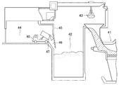
一般に、廃棄物処理施設、例えば、都市ごみ等を焼却処理するごみ処理施設においては、ごみ収集車40により搬入されて来たごみをごみ焼却炉41に隣接して設けたごみピット42に一旦投入し、その後ごみピット42内のごみをバケットクレーン43によりごみ焼却炉41に投入して焼却処理している(特許文献1参照)。
In general, in a waste treatment facility, for example, a waste treatment facility that incinerates municipal waste, etc., the waste brought in by the
また、ごみ処理施設には、ごみピット42に隣接してごみ収集車40が進入するプラットホーム44が設けられており、このプラットホーム44とごみピット42との間には、ごみ収集車40のごみをごみピット42に投入するための投入扉付のごみ投入口46が設けられている(特許文献1参照)。
In addition, the waste disposal facility is provided with a
而して、プラットホーム44に進入したごみ収集車40は、前記ごみ投入口46にごみを投入する際、ごみ投入口46に向って後ろ向きで進み、ごみ投入口46近傍の床面に設けた車止め47の位置で停車した後、投入扉を開放したごみ投入口46へごみを投入するようにしている(特許文献1参照)。
Thus, when the
しかし、ごみ収集車により収集されたごみの中に金属、瓦礫等の燃焼不適物やスプレー缶等の危険物等が含まれている場合、ごみ収集車から直接ごみピットにごみを投入せず、プラットホームに設置したダンピングボックスに一旦ごみを投棄し、燃焼不適物や危険物の検査や取り除きを行った後、ダンピングボックス内のごみをごみピットに投入するようにしている(例えば、特許文献2及び特許文献3参照)。
However, if the garbage collected by the garbage truck contains non-combustible materials such as metal and rubble, and dangerous materials such as spray cans, do not throw garbage directly into the garbage pit from the garbage truck. After dumping garbage in a dumping box installed on the platform and inspecting and removing unsuitable and dangerous materials, the dust in the dumping box is thrown into the garbage pit (for example,
また、ダンプ機能を備えていないトラック等によりごみが収集された場合も、トラックの荷台から人力によってごみをごみピットへ直接投入する作業は、転落事故の危険があるので、ダンピングボックスを使用してごみをごみピットに投入するようにしている。 In addition, even if garbage is collected by a truck that does not have a dump function, it is dangerous to manually put the garbage from the truck bed into the garbage pit. Garbage is thrown into the garbage pit.
図9は従来のダンピングボックスの一例を示すものであり、当該ダンピングボックスは、図9(a)〜(c)に示すようにごみの投入方式により形式が異なっている。 FIG. 9 shows an example of a conventional dumping box, and the type of the dumping box differs depending on the method of throwing in garbage as shown in FIGS. 9 (a) to 9 (c).
即ち、図9(a)はプッシャ型のダンピングボックスであり、ごみ収集車20からダンピングボックス21にごみをダンプし、燃焼不適物等の検査や取り除きを行った後、ダンピングボックス21内のごみを油圧シリンダ22により駆動されるプッシャ23を用いてごみピット24内へ押し出すようにしたものである。
That is, FIG. 9A shows a pusher type dumping box. Dumps are dumped from the
また、図9(b)は傾胴型のダンピングボックスであり、ごみ収集車20からダンピングボックス21にごみをダンプし、燃焼不適物等の検査や取り除きを行った後、ダンピングボックス21を油圧シリンダ22により上方へ持ち上げて傾斜させ、ダンピングボックス21以内のごみをごみピット24内へ投入するようにしたものである。
FIG. 9B shows a tilting barrel type dumping box. Dumps are dumped from the
更に、図9(c)は傾斜投入型のダンピングボックスであり、ごみ収集車20からダンピングボックス21にごみをダンプし、燃焼不適物等の検査や取り除きを行った後、ダンピングボックス21を油圧シリンダ22により下方へ傾け、ダンピングボックス21内のごみをごみピット24内へ投入するようにしたものである。
Further, FIG. 9 (c) shows an inclined dumping type dumping box. Dumps are dumped from the
しかしながら、図9(a)〜(c)に示す従来のダンピングボックス21においては、
プラットホーム25にダンピングボックス21を設置しなければならず、ダンピングボックス21専用のごみ投入扉が必要であり、通常の投入扉と兼用できず、ごみ収集車20の同時排出できる台数が少なくなり、作業効率が悪いと云う問題があった。
However, in the
A
そこで、前記問題を解決する技術として、特開平8−217193号公報(特許文献4)には、ダンピングボックスと通常のごみ投入扉を組み合わせ、選別を要するごみと選別を要しないごみを同じごみ投入扉から同じごみ投入口を介してごみピットへ投入できるようにしたダンピングボックス兼ごみ投入扉が記載されている。 Therefore, as a technique for solving the above-mentioned problem, Japanese Patent Application Laid-Open No. 8-217193 (Patent Document 4) combines a dumping box and a normal waste input door to input waste that requires sorting and waste that does not need sorting. A dumping box / garbage entry door is described that allows entry into the garbage pit from the door through the same garbage entry port.
しかし、前記ダンピングボックス兼ごみ投入扉においても、ごみを検査する際にはごみ収集車が来るまでに準備しなければならず、作業性に劣ると云う問題があった。 However, the dumping box / garbage entry door also has a problem that it is inferior in workability because it must be prepared before the garbage truck comes when inspecting the garbage.
本発明は、このような問題点に鑑みて為されたものであり、その目的は、廃棄物収集車がプラットホーム内で切り返し運転や後退運転をすることなく、廃棄物をダンプすることができ、安全性及び作業効率を高められるようにした廃棄物処理施設のダンピング装置を提供することにある。 The present invention has been made in view of such problems, and the purpose thereof is to allow the waste collection vehicle to dump the waste without turning back or driving in the platform, It is an object of the present invention to provide a dumping apparatus for a waste treatment facility that can improve safety and work efficiency.
本発明の請求項1の発明は、廃棄物処理施設のプラットホームの床に設けられ、プラットホームに進入した廃棄物収集車から排出された廃棄物を受け入れる開口部と、プラットホームの床下に設けられ、開口部と廃棄物ピットとを連通状態にする廃棄物搬送路と、開口部に昇降自在に配設されて開口部を開閉するダンピング蓋と、ダンピング蓋を昇降自在且つ移動自在に支持する蓋支持装置とを備え、前記ダンピング蓋は、開口部を閉塞して廃棄物収集車がダンピング蓋を乗り越えられるようにする上昇位置と、上昇位置から下降して開口部の内周面とダンピング蓋の上面との間に廃棄物を受け入れるダンピングスペースを形成する下降位置と、下降位置から移動し、ダンピングスペースに排出されてダンピング蓋に載っている廃棄物を開口部の内周縁部で掻き落す掻き落し位置とを取り得るように構成されていることに特徴がある。
The invention according to
本発明の請求項2の発明は、開口部、ダンピング蓋及び蓋支持装置を、プラットホームの床に廃棄物収集車の進行方向に交差する方向に並列状に配置し、また、廃棄物搬送路を、プラットホームの床下に廃棄物収集車の進行方向に交差する方向に沿って設けたことに特徴がある。 According to a second aspect of the present invention, the opening, the dumping lid, and the lid support device are arranged in parallel on the platform floor in a direction crossing the traveling direction of the waste collection vehicle, and the waste transport path is provided. It is characterized in that it is provided along the direction crossing the traveling direction of the waste collection vehicle under the floor of the platform.
本発明の請求項3の発明は、廃棄物搬送路内に、廃棄物収集車から開口部に投入された廃棄物を廃棄物ピットへ搬送する廃棄物搬送装置を設けたことに特徴がある。
The invention of
本発明の請求項4の発明は、開口部の内周縁部に、ダンピング蓋に載っている廃棄物を掻き取る掻き取り手段を設けたことに特徴がある。
The invention according to
本発明の廃棄物処理施設のダンピング装置は、開口部と、廃棄物搬送路と、ダンピング蓋と、蓋支持装置とを備えており、前記ダンピング蓋が、蓋支持装置によって、開口部を閉塞して廃棄物収集車がダンピング蓋を乗り越えられるようにする上昇位置と、ダンピング蓋が上昇位置から下降して開口部の内周面とダンピング蓋の上面との間に廃棄物を受け入れるダンピングスペースを形成する下降位置と、下降位置から移動し、ダンピングスペースに排出されてダンピング蓋に載っている廃棄物を開口部の内周縁部で掻き落す掻き落し位置とを取り得るように構成されているため、ダンピング蓋を上昇位置にすると、廃棄物収集車がダンピング蓋を前進で乗り越えることができ、また、廃棄物収集車がダンピング蓋を乗り越えた位置で停車し、この状態でダンピング蓋を下降位置にすると、ダンピングスペースが形成されてここに廃棄物収集車の廃棄物を投棄することができ、更に、ダンピング蓋を下降位置から掻き落し位置にすると、ダンピング蓋に載っている廃棄物が落下するので、この落下した廃棄物を例えば廃棄物搬送路に設けた廃棄物搬送装置により廃棄物ピットに投入することができ、そして、ダンピング蓋を乗り越えて停車している廃棄物収集車は、前進で退出することができる。 A dumping device for a waste treatment facility according to the present invention includes an opening, a waste transport path, a damping lid, and a lid support device, and the damping lid closes the opening by the lid support device. The raising position that allows the waste collection vehicle to get over the damping lid, and the damping lid descends from the raised position to form a damping space for receiving waste between the inner peripheral surface of the opening and the upper surface of the damping lid. Because it is configured to be able to take a lowering position that moves and a scraping position that moves from the lowering position, and scrapes the waste that is discharged into the dumping space and placed on the damping lid at the inner peripheral edge of the opening, When the dumping lid is in the raised position, the waste collection vehicle can move over the dumping lid forward, and the waste collection vehicle stops at the position over the damping lid. In this state, when the dumping lid is in the lowered position, a dumping space is formed, and the waste collection vehicle waste can be dumped here, and when the dumping lid is scraped from the lowered position to the dumping lid, Since the loaded waste falls, the dropped waste can be thrown into the waste pit by, for example, a waste transport device provided in the waste transport path, and the vehicle stops over the dumping lid. The waste collection vehicle can be moved forward.
このように、本発明の廃棄物処理施設のダンピング装置は、廃棄物収集車がプラットホームの床に設置したダンピング装置の開口部に廃棄物を投入する際に、廃棄物収集車を直進移動させるだけで良いので、廃棄物収集車の切り返し運転や後退運転をする必要がなくなると共に、開口部への転落防止を図れ、安全性及び作業効率を高めることができる。 As described above, the dumping device of the waste treatment facility according to the present invention simply moves the waste collecting vehicle straight when the waste collecting vehicle throws the waste into the opening of the damping device installed on the floor of the platform. Therefore, it is not necessary to turn over or reverse the waste collection vehicle, prevent falling to the opening, and improve safety and working efficiency.
また、本発明の廃棄物処理施設のダンピング装置は、ダンピング蓋の下降により開口部にダンピングスペースを形成することができると共に、ダンピング蓋上の廃棄物を廃棄物搬送装置上へ落下させて廃棄物搬送装置により廃棄物ピットへ投入することができるため、選別を要する廃棄物、選別を要しない廃棄物に関係なく、同じ開口部に廃棄物を投入することができ、選別を要する廃棄物、選別を要しない廃棄物の何れにも対応することができる。その結果、廃棄物収集車は、廃棄物の選別の有無にかかわらず、停車位置が同じになり、運転手が停車位置を誤認して廃棄物収集車がダンピングボックスと接触したり、廃棄物投入口から廃棄物ピットへ落下するのを防ぐことができる。 In addition, the dumping device of the waste treatment facility according to the present invention can form a dumping space in the opening by lowering the dumping lid, and the waste on the dumping lid is dropped onto the waste transporting device and discarded. Since it can be thrown into the waste pit by the transport device, it can be thrown into the same opening regardless of waste that requires sorting and waste that does not require sorting. It is possible to deal with any of the wastes that do not require. As a result, the waste collection vehicle has the same stop position regardless of whether or not waste is sorted, the driver misidentifies the stop position, the waste collection vehicle comes into contact with the dumping box, or the waste input It can prevent falling from the mouth to the waste pit.
更に、本発明の廃棄物処理施設のダンピング装置は、廃棄物収集車が万一開口部に転落しても、ダンピングボックスから廃棄物ピットに転落する場合に比較して落差が大幅に小さくなり、大事故につながることがない。 Furthermore, the dumping device of the waste treatment facility of the present invention has a drastically reduced drop compared to the case where the dump truck falls into the waste pit even if it falls into the opening. It will not lead to a major accident.
更に、本発明の廃棄物処理施設のダンピング装置は、開口部、ダンピング蓋及び蓋支持装置を、プラットホームの床に廃棄物収集車の進行方向に交差する方向に並列状に配置し、また、廃棄物搬送路及び廃棄物搬送装置を、プラットホームの床下に廃棄物収集車の進行方向に交差する方向に沿って設けているため、開口部、ダンピング蓋及び蓋支持装置が複数あっても、廃棄物搬送路は一つだけで良く、また、廃棄物搬送装置も一基だけで良く、コスト削減を図ることができる。 Furthermore, the dumping device for a waste treatment facility according to the present invention has an opening, a dumping lid, and a lid support device arranged in parallel on the platform floor in a direction crossing the traveling direction of the waste collection vehicle. Since the material transport path and the waste transport device are provided under the platform along the direction intersecting the direction of travel of the waste collection vehicle, the waste can be disposed even if there are a plurality of openings, damping lids, and lid support devices. Only one conveying path is required, and only one waste conveying apparatus is required, and cost reduction can be achieved.
更に、本発明の廃棄物処理施設のダンピング装置は、開口部の内周縁部にダンピング蓋に載っている廃棄物を掻き取る掻き取り手段を設けているため、ダンピング蓋上の廃棄物を確実且つ良好に落とすことができ、後続の廃棄物収集車が廃棄物を踏んでプラットホームの床に撒き散らすと云うことがない。 Furthermore, since the dumping device for the waste treatment facility of the present invention is provided with a scraping means for scraping the waste placed on the damping lid at the inner peripheral edge of the opening, the waste on the damping lid can be reliably and It can be dropped well, and subsequent waste collection vehicles will not step on the waste and sprinkle on the platform floor.
以下、本発明の実施の形態を図面に基づいて詳細に説明する。
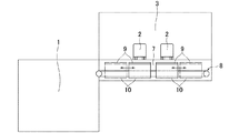
図1及び図2は本発明の実施の形態に係る廃棄物処理施設のダンピング装置を設置した廃棄物処理施設の一例を示し、当該廃棄物処理施設は、廃棄物を焼却する廃棄物焼却炉(図示省略)と、廃棄物を貯留する廃棄物ピット1と、廃棄物ピット1に隣接して設けられ、廃棄物収集車2が進入するプラットホーム3等を備えたごみ処理施設に構成されており、ており、プラットホーム3に進入した廃棄物収集車2から排出された廃棄物をダンピング装置により受け取って検査した後、検査後の廃棄物をダンピング装置により廃棄物ピット1へ投入したり、或いは、廃棄物収集車2から排出された廃棄物を検査せずに廃棄物ピット1へ投入できるようになっている。
尚、ここで、廃棄物処理施設とは、都市ごみや産業廃棄物等の廃棄物の焼却処理や分別処理を行うごみ処理施設、チップ状にした木材やバガス(サトウキビの搾りかす)等の廃棄物から発電を行うバイオマスエネルギー生成施設、家畜の糞尿や生ごみ等の廃棄物からメタンガスを精製するメタン発酵処理施設、廃プラスチック類や木くず等の廃棄物から固形燃料を成形するRPF製造施設、籾柄や稲わら、生ごみ等の廃棄物を発酵させて堆肥を作成する堆肥化施設等を含むものとする。
Hereinafter, embodiments of the present invention will be described in detail with reference to the drawings.
1 and 2 show an example of a waste treatment facility in which a dumping device for a waste treatment facility according to an embodiment of the present invention is installed. The waste treatment facility includes a waste incinerator ( (Not shown), a
Here, the waste treatment facility is a waste treatment facility that incinerates and separates waste such as municipal waste and industrial waste, and waste such as chip-shaped wood and bagasse (sugar cane residue). Biomass energy generation facility that generates electricity from waste, methane fermentation treatment facility that purifies methane gas from waste such as livestock manure and garbage, RPF manufacturing facility that molds solid fuel from waste such as waste plastics and wood scrap, It shall include composting facilities that fertilize wastes such as handles, rice straw, and garbage to create compost.
前記プラットホーム3は、その両側(図1の上側及び下側)に廃棄物収集車2の入口4及び出口5が対向する状態で設けられており、廃棄物収集車2が入口4からプラットホーム3内に進入し、プラットホーム3内を直進移動して出口5から退出できるようになっていると共に、その途中において廃棄物収集車2からダンピング装置に廃棄物を投棄できるようになっている。
The
廃棄物処理施設のダンピング装置は、プラットホーム3の床に設けられ、プラットホーム3に進入した廃棄物収集車2から排出された廃棄物を受け入れる開口部6と、プラットホーム3の床下に設けられ、開口部6と廃棄物ピット1とを連通状態にする廃棄物搬送路7と、廃棄物搬送路7内に設けられ、廃棄物収集車2から開口部6に投入された廃棄物を廃棄物ピット1へ搬送する廃棄物搬送装置8と、開口部6に昇降自在に配設されて開口部6を開閉すると共に、下降時に廃棄物搬送路7内を廃棄物搬送装置8に沿って移動自在なダンピング蓋9と、廃棄物搬送路7内に設けられ、ダンピング蓋9を昇降自在且つ移動自在に支持する蓋支持装置10とから構成されている。
The dumping device of the waste treatment facility is provided on the floor of the
具体的には、前記開口部6は、プラットホーム3の床に複数設けられており、この実施の形態においては、矩形状の二つの開口部6がプラットホーム3の床に廃棄物収集車2の進行方向に交差(この例では直交)する方向に並列状に配置されている。
Specifically, a plurality of the
また、二つの開口部6の間隔は、プラットホーム3内を入口4側から出口5側へ向って直進移動する二台の廃棄物収集車2が各開口部6を通過する際に互いに干渉しないように設定されていると共に、各開口部6の幅(図1の左右方向の幅)は、廃棄物収集車2の幅よりも広く設定されている。
Further, the interval between the two
更に、各開口部6のダンピング蓋9が通過する内周縁部6aには、図6(c)に示す如く、ダンピング蓋9が移動する際にダンピング蓋9に載っている廃棄物を掻き取る掻き取り手段が設けられている。この掻き取り手段として、プラスチック材又は金属材等により形成されたスクレーパー12が使用されている。このスクレーパー12は、その下端部がダンピング蓋9の上面を摺動するように開口部6の内周縁部6aに取り付けられている。
Further, as shown in FIG. 6C, the inner
前記廃棄物搬送路7は、プラットホーム3の床下で且つ開口部6の下方位置に廃棄物収集車2の進行方向に交差(この例では直交)する姿勢で設けられており、二つの開口部6と廃棄物ピット1とを連通状態にするものである。この廃棄物搬送路7の高さ及び幅は、廃棄物搬送路7内に廃棄物搬送装置8及び蓋支持装置10等を収容できる程度に設定されている。
The
前記廃棄物搬送装置8は、廃棄物搬送路7内に二つの開口部6から廃棄物ピット1に亘って設けられており、廃棄物収集車2から各開口部6に投入された廃棄物を受け取って廃棄物ピット1側へ搬送し、廃棄物搬送路7の終端部から廃棄物ピット1内へ投入するものである。この廃棄物搬送装置8には、従来公知のベルトコンベア等が使用されている。
The
前記ダンピング蓋9は、廃棄物収集車2が直進で開口部6を通過する際にプラットホーム3の床面と面一又はほぼ面一になって開口部6を閉塞し、また、廃棄物収集車2が開口部6を乗り越えて停車し、廃棄物収集車2から開口部6に廃棄物を投入際にプラットホーム3の床面から下降して開口部6の内周面とダンピング蓋9の上面との間に廃棄物を受け入れる上方が開放されたダンピングスペースを形成するものであり、ダンピングスペースに排出された廃棄物を受け取るものである。
The dumping
また、ダンピング蓋9は、開口部6の形状と同じ矩形状に形成されていると共に、廃棄物収集車2の荷重に耐えられる強度を備えている。このダンピング蓋9の大きさは、開口部6内に位置したときに、廃棄物が開口部6の内周面とダンピング蓋9の外周縁との隙間から廃棄物搬送路7内に落ち込まないように設定されている。
The damping
前記蓋支持装置10は、ダンピング蓋9を開口部6内で昇降自在且つ廃棄物搬送装置8に沿って移動自在に支持するものであり、廃棄物搬送路7の床に設けたレール11上を廃棄物搬送装置8に沿って走行する台車10aと、台車10a上に立設され、ダンピング蓋9を昇降自在に支持する複数本の柱材10bと、台車10aに設けられ、台車10aを走行駆動する移動用駆動部(図示省略)と、台車10a又は柱材10bに設けられ、ダンピング蓋9を昇降させる昇降用駆動部(図示省略)とから構成されている。この蓋支持装置10は、廃棄物搬送装置8と干渉しないように廃棄物搬送路7内に設けられている。
The
尚、移動用駆動部は、例えば、台車10aをレール11に沿って移動させるシリンダ又は台車10aの車輪を回転駆動するモータ等から成り、台車10a及び柱材10bを開口部6の真下に位置する廃棄物受け取り位置(図3の実線位置)から廃棄物搬送路7の天井面の下方に位置する廃棄物排出位置(図3の一点鎖線位置)へ若しくは台車10a及び柱材10bを廃棄物排出位置から廃棄物受け取り位置へ移動させるものである。
The moving drive unit includes, for example, a cylinder that moves the
また、昇降用駆動部は、例えば、ダンピング蓋9を昇降動させるシリンダ等から成り、ダンピング蓋9を開口部6内で上昇させてプラットホーム3の床面と面一又はほぼ面一にする上昇位置(図3の実線位置)と、ダンピング蓋9を開口部6内で下降させて開口部6の内周面とダンピング蓋9の上面との間に廃棄物を受け入れるダンピングスペースを形成する下降位置(図3の二点鎖線位置)とに亘って昇降動させるものである。
Moreover, the raising / lowering drive part consists of a cylinder etc. which raise / lower the damping
従って、ダンピング装置のダンピング蓋9は、前記蓋支持装置10によって、開口部6を閉塞して廃棄物収集車2がダンピング蓋9を乗り越えられるようにする上昇位置(図3の実線位置)と、上昇位置から下降して廃棄物搬送路7内に位置し、開口部6の内周面とダンピング蓋9の上面との間に廃棄物を受け入れるダンピングスペースを形成する下降位置(図3の二点鎖線位置)と、下降位置から廃棄物搬送路7内を廃棄物搬送装置8に沿って移動し、ダンピングスペースに排出されてダンピング蓋9上に載っている廃棄物を開口部6の内周縁部で掻き落して廃棄物搬送装置8上へ落下させる掻き落し位置(図3の一点鎖線位置)とを取り得るようになっている。
Therefore, the dumping
尚、上記の実施の形態においては、ダンピング蓋9が下降してダンピングスペースを形成するときに廃棄物搬送路7内に位置するようにしたが、他の実施の形態においては、図5(c)に示す如く、下降するダンピング蓋9を開口部6内の下部位置で停止させ、開口部6の内周面とダンピング蓋9の上面との間に廃棄物を受け入れるダンピングスペースを形成するようにしても良い。この場合、ダンピング蓋9を廃棄物搬送装置8に沿って移動させる際には、更にダンピング蓋9を下降させて廃棄物搬送路7内に位置させる。即ち、ダンピング蓋9は、二段階に亘って下降することになる。
In the above embodiment, when the damping
次に、廃棄物収集車2により回収した廃棄物を廃棄物処理施設のプラットホーム3に設けたダンピング装置に投入する場合について説明する。
Next, a case where the waste collected by the
回収した廃棄物の中に燃焼不燃物や危険物が含まれていない場合、廃棄物収集車2は、プラットホーム3の入口4からプラットホーム3内に進入した後、廃棄物収集車2が停車しておらず、且つ上昇位置にあるダンピング蓋9により閉塞されている開口部6へ向って直進する。
If the collected waste does not contain burning incombustibles or hazardous materials, the
廃棄物収集車2は、ダンピング蓋9により閉塞されている開口部6に近づくと、スピードを緩めて前進し、開口部6及びダンピング蓋9を直進で乗り越え、後輪が開口部6及びダンピング蓋9を完全に乗り越えた時点で停止する。
When the
廃棄物収集車2が停車したら、ダンピング蓋9が蓋支持装置10により上昇位置から下降位置へ下降し、且つ下降位置から廃棄物搬送路7内を廃棄物搬送装置8に沿って移動し、開口部6を完全に開放する。
When the
尚、蓋支持装置10は、プラットホーム3の廃棄物収集車2が停車する床にセンサー(図示省略)を埋設し、このセンサーが廃棄物収集車2の停車を検出したら、駆動するように制御されている。
The
開口部6が完全に開放されたら、廃棄物収集車2の廃棄物収納部を傾けて廃棄物を開口部6に投入する。投入した廃棄物は、廃棄物搬送装置8に受け取られ、廃棄物搬送装置8により廃棄物ピット1側へ搬送され、廃棄物搬送装置8の終端部から廃棄物ピット1内に投入される。また、廃棄物収集車2は、プラットホーム3内を直進して出口5から退出する。更に、ダンピング蓋9は、蓋支持装置10により上昇位置に復帰し、廃棄物収集車2が開口部6及びダンピング蓋9を乗り越えられるようにする。
When the
一方、回収した廃棄物の中に燃焼不燃物や危険物が含まれているか否かの検査や取り除きを行う場合、廃棄物収集車2は、プラットホーム3の入口4からプラットホーム3内に進入した後、廃棄物収集車2が停車しておらず、且つ上昇位置にあるダンピング蓋9により閉塞されている開口部6へ向って直進する。
On the other hand, when inspecting or removing whether or not the collected waste contains incombustible or incombustible material, the
廃棄物収集車2は、ダンピング蓋9により閉塞されている開口部6に近づくと、スピードを緩めて前進し、開口部6及びダンピング蓋9を直進で乗り越えて行く。
When the
廃棄物収集車2は、後輪が開口部6及びダンピング蓋9を完全に乗り越えたら、その位置で停止する(図4参照)。
When the rear wheel has completely passed over the
廃棄物収集車2が停車したら、ダンピング蓋9が蓋支持装置10により上昇位置から下降位置へ下降する。これにより、開口部6の内周面とダンピング蓋9の上面との間に廃棄物を受け入れるダンピングスペースが形成される(図5参照)。
When the
尚、蓋支持装置10は、プラットホーム3の廃棄物収集車2が停車する床にセンサー(図示省略)を埋設し、このセンサーが廃棄物収集車2の停車を検出したら、駆動するように制御されている。
The
開口部6にダンピングスペースが形成されたら、廃棄物収集車2の廃棄物収納部を傾けて廃棄物をダンピングスペースに排出すると共に、ダンピングスペース内の廃棄物の中から燃焼不適物や危険物等を検査して除去する。
When the dumping space is formed in the
ダンピングスペース内の廃棄物の検査が終了したら、ダンピング蓋9が蓋支持装置10により下降位置から廃棄物搬送装置8に沿って移動し、掻き落し位置側へ移動する(図6参照)。これにより、ダンピング蓋9に載っている廃棄物は、開口部6の内周縁部6aで掻き落され、廃棄物搬送装置8上に落下する。
尚、廃棄物搬送装置8及び蓋支持装置10等は、開口部6の内周縁部で掻き落された廃棄物が廃棄物搬送装置8上へ確実且つ良好に落下するように工夫されていることは勿論である。
When the inspection of the waste in the dumping space is completed, the dumping
It should be noted that the
廃棄物搬送装置8上に落下した廃棄物は、廃棄物搬送装置8により廃棄物ピット1側へ搬送され、廃棄物搬送装置8の終端部から廃棄物ピット1内に投入される。また、廃棄物収集車廃棄物2は、プラットホーム3内を直進して出口5から退出する。
The waste dropped on the
そして、ダンピング蓋9上の全ての廃棄物が廃棄物搬送装置8上に落下したら、ダンピング蓋9は、蓋支持装置10により掻き落し位置から下降位置に戻り、更に下降位置から上昇位置に戻って廃棄物収集車2が開口部6及びダンピング蓋9を乗り越えられるようにする(図7参照)。
When all the waste on the dumping
このように、上述した廃棄物処理施設のダンピング装置は、ダンピング装置の開口部6に廃棄物を投入する際に、廃棄物収集車2を直進移動させるだけで良いので、廃棄物収集車2の切り返し運転や後退運転をする必要がなく、安全性及び作業効率を高めることができる。
As described above, the dumping device of the waste treatment facility described above only has to move the
また、ダンピング装置は、ダンピング蓋9の下降により開口部6に廃棄物を受け入れるダンピングスペースを形成することができると共に、ダンピング蓋9上の廃棄物を廃棄物搬送装置8上へ落下させて廃棄物搬送装置8により廃棄物ピット1へ投入することができるため、選別を要する廃棄物、選別を要しない廃棄物に関係なく、同じ開口部6に廃棄物を投入することができ、選別を要する廃棄物、選別を要しない廃棄物の何れにも対応することができる。
Further, the dumping device can form a dumping space for receiving waste in the
更に、ダンピング装置は、廃棄物収集車2が万一開口部6に転落しても、ダンピングボックスから廃棄物ピット1に転落する場合に比較して落差が大幅に小さくなり、大事故につながることがない。
Furthermore, even if the
尚、上記の実施の形態においては、開口部6、ダンピング蓋9及び蓋支持装置10を、プラットホーム3の床に廃棄物収集車2の進行方向に直交する方向に並列状に二つずつ配置するようにしたが、開口部6、ダンピング蓋9及び蓋支持装置10の数や配置状態は、上記の実施の形態に限定されるものではなく、本発明の趣旨を逸脱しない範囲において種々の変更が可能である。
In the above-described embodiment, two
また、上記の実施の形態においては、蓋支持装置10を台車10a、柱材10b、移動用駆動部及び昇降用駆動部から構成したが、蓋支持装置10は、上記の実施の形態に限定されるものではなく、ダンピング蓋9を上昇位置、下降位置、掻き落し位置に昇降又は移動させることができれば、如何なる構造のものであっても良い。
Moreover, in said embodiment, although the
更に、上記の実施の形態においては、廃棄物搬送装置8としてベルトコンベアを例示したが、他の実施の形態においては、廃棄物搬送装置8としてプッシャやバッチ移動式のバケット等でも良く、廃棄物を搬送することができれば、如何なる形式のものであっても良い。
また、廃棄物搬送装置8を省略すると共に、廃棄物搬送路7を廃棄物ピット1側へ下り傾斜状に設け、開口部6から廃棄物搬送路7内に落下した廃棄物を廃棄物搬送路7の床面を滑らせて廃棄物ピット1へ送るようにしても良く、或いは、開口部6から直接廃棄物ピット1に廃棄物を落下させるようにしても良い。
Furthermore, in the above embodiment, a belt conveyor is exemplified as the
Further, the
1は廃棄物ピット
2は廃棄物収集車
3はプラットホーム
4は入口
5は出口
6は開口部
6aは開口部の内周縁部
7は廃棄物搬送路
8は廃棄物搬送装置
9はダンピング蓋
10は蓋支持装置
10aは台車
10bは柱材
11はレール
12はスクレーパー
1 is a
Claims (4)
Priority Applications (1)
| Application Number | Priority Date | Filing Date | Title |
|---|---|---|---|
| JP2015184241A JP6491580B2 (en) | 2015-09-17 | 2015-09-17 | Dumping equipment for waste treatment facilities |
Applications Claiming Priority (1)
| Application Number | Priority Date | Filing Date | Title |
|---|---|---|---|
| JP2015184241A JP6491580B2 (en) | 2015-09-17 | 2015-09-17 | Dumping equipment for waste treatment facilities |
Publications (2)
| Publication Number | Publication Date |
|---|---|
| JP2017057066A JP2017057066A (en) | 2017-03-23 |
| JP6491580B2 true JP6491580B2 (en) | 2019-03-27 |
Family
ID=58391352
Family Applications (1)
| Application Number | Title | Priority Date | Filing Date |
|---|---|---|---|
| JP2015184241A Active JP6491580B2 (en) | 2015-09-17 | 2015-09-17 | Dumping equipment for waste treatment facilities |
Country Status (1)
| Country | Link |
|---|---|
| JP (1) | JP6491580B2 (en) |
Families Citing this family (1)
| Publication number | Priority date | Publication date | Assignee | Title |
|---|---|---|---|---|
| CN109305570B (en) * | 2018-11-13 | 2019-05-21 | 哈尔滨理工大学 | A kind of box-packed bulk cargo overturning delivery device |
Family Cites Families (8)
| Publication number | Priority date | Publication date | Assignee | Title |
|---|---|---|---|---|
| FR2249006A1 (en) * | 1973-10-30 | 1975-05-23 | Frossard J | Domestic rubbish tipping system - uses intermediate tipping area and trolley to move rubbish to main tipping area |
| JPS5488674A (en) * | 1977-12-23 | 1979-07-13 | Nippon Sharyo Seizo Kk | Device for loading refuse incinerator |
| JPS5535771A (en) * | 1978-09-04 | 1980-03-12 | Shin Meiwa Ind Co Ltd | Garbage treatment apparatus |
| JPS5834806U (en) * | 1981-08-28 | 1983-03-07 | 日本鋼管株式会社 | Openable garbage chute |
| JPS63117801A (en) * | 1986-11-07 | 1988-05-21 | 極東開発工業株式会社 | Waste charger |
| US4834300A (en) * | 1988-03-07 | 1989-05-30 | Wojciechowski Christopher R | Method and apparatus for solid waste disposal |
| JPH11139505A (en) * | 1997-11-12 | 1999-05-25 | Shin Meiwa Ind Co Ltd | Garbage accepting device and its method |
| JP2001153326A (en) * | 1999-11-29 | 2001-06-08 | Kyokuto Kaihatsu Kogyo Co Ltd | Refuse treatment facility |
-
2015
- 2015-09-17 JP JP2015184241A patent/JP6491580B2/en active Active
Also Published As
| Publication number | Publication date |
|---|---|
| JP2017057066A (en) | 2017-03-23 |
Similar Documents
| Publication | Publication Date | Title |
|---|---|---|
| JP5570792B2 (en) | Garbage separation device | |
| US10464745B2 (en) | Modular waste transfer station (MWTS) | |
| JP6491580B2 (en) | Dumping equipment for waste treatment facilities | |
| JPH10192729A (en) | Solid matter pulverizing vehicle | |
| JP6585442B2 (en) | Waste input method and waste treatment facility in waste treatment facility | |
| EP0667489A2 (en) | Method and device for processing waste materials before their incineration | |
| RU2282506C1 (en) | Solid garbage classifying method and complex for performing the same | |
| JP2005154039A (en) | Refuse carrying-in device for refuse disposal facility, and refuse carrying-in method | |
| JP6544856B2 (en) | Vehicle stop system for straight ahead vehicles | |
| JPH115589A (en) | Waste material processing plant barge | |
| EP2241499B1 (en) | Marine vessel based system and method of managing municipal solid waste | |
| RU2301711C1 (en) | Method of sorting of the solid wastes and the complex for its realization | |
| TWI236451B (en) | Automatic conveyance system for transferring scrap glass | |
| JP2005305225A (en) | Pretreatment method and pretreatment apparatus for garbage | |
| JP2001153326A (en) | Refuse treatment facility | |
| DE102021129068A1 (en) | Process for backfilling and disposal of ash-like combustion products in silo vehicles | |
| RU2282507C1 (en) | Method for classifying solid waste materials and complex for performing the same | |
| US648279A (en) | Means for handling refuse. | |
| JP3723345B2 (en) | Incineration ash final treatment system | |
| JP2001261105A (en) | Classifying container for waste | |
| KR930000177B1 (en) | Apparatus and method for sorting trash | |
| RU2283193C1 (en) | Method and device for classifying solid waste | |
| JP2023176380A (en) | platform | |
| JP2003012107A (en) | Waste disposal system | |
| JPH11139504A (en) | Method for accepting/delivering waste |
Legal Events
| Date | Code | Title | Description |
|---|---|---|---|
| A621 | Written request for application examination |
Free format text: JAPANESE INTERMEDIATE CODE: A621 Effective date: 20180525 |
|
| A977 | Report on retrieval |
Free format text: JAPANESE INTERMEDIATE CODE: A971007 Effective date: 20190212 |
|
| TRDD | Decision of grant or rejection written | ||
| A01 | Written decision to grant a patent or to grant a registration (utility model) |
Free format text: JAPANESE INTERMEDIATE CODE: A01 Effective date: 20190219 |
|
| A61 | First payment of annual fees (during grant procedure) |
Free format text: JAPANESE INTERMEDIATE CODE: A61 Effective date: 20190301 |
|
| R150 | Certificate of patent or registration of utility model |
Ref document number: 6491580 Country of ref document: JP Free format text: JAPANESE INTERMEDIATE CODE: R150 |
|
| R250 | Receipt of annual fees |
Free format text: JAPANESE INTERMEDIATE CODE: R250 |
|
| R250 | Receipt of annual fees |
Free format text: JAPANESE INTERMEDIATE CODE: R250 |
|
| S531 | Written request for registration of change of domicile |
Free format text: JAPANESE INTERMEDIATE CODE: R313531 |
|
| R350 | Written notification of registration of transfer |
Free format text: JAPANESE INTERMEDIATE CODE: R350 |
|
| R250 | Receipt of annual fees |
Free format text: JAPANESE INTERMEDIATE CODE: R250 |