JP6479400B2 - Fuel cell device and fuel cell system - Google Patents
Fuel cell device and fuel cell system Download PDFInfo
- Publication number
- JP6479400B2 JP6479400B2 JP2014210111A JP2014210111A JP6479400B2 JP 6479400 B2 JP6479400 B2 JP 6479400B2 JP 2014210111 A JP2014210111 A JP 2014210111A JP 2014210111 A JP2014210111 A JP 2014210111A JP 6479400 B2 JP6479400 B2 JP 6479400B2
- Authority
- JP
- Japan
- Prior art keywords
- current collector
- cell
- cell stack
- electrode current
- region
- Prior art date
- Legal status (The legal status is an assumption and is not a legal conclusion. Google has not performed a legal analysis and makes no representation as to the accuracy of the status listed.)
- Active
Links
Images


Classifications
-
- Y—GENERAL TAGGING OF NEW TECHNOLOGICAL DEVELOPMENTS; GENERAL TAGGING OF CROSS-SECTIONAL TECHNOLOGIES SPANNING OVER SEVERAL SECTIONS OF THE IPC; TECHNICAL SUBJECTS COVERED BY FORMER USPC CROSS-REFERENCE ART COLLECTIONS [XRACs] AND DIGESTS
- Y02—TECHNOLOGIES OR APPLICATIONS FOR MITIGATION OR ADAPTATION AGAINST CLIMATE CHANGE
- Y02E—REDUCTION OF GREENHOUSE GAS [GHG] EMISSIONS, RELATED TO ENERGY GENERATION, TRANSMISSION OR DISTRIBUTION
- Y02E60/00—Enabling technologies; Technologies with a potential or indirect contribution to GHG emissions mitigation
- Y02E60/30—Hydrogen technology
- Y02E60/50—Fuel cells
Description
本発明は、燃料電池装置および燃料電池システムに関する。 The present invention relates to a fuel cell device and a fuel cell system.
従来、都市ガス、天然ガス、石油、メタノール、石炭ガス化ガスなどを燃料として運転される燃料電池が知られている。燃料電池の一つである固体酸化物形燃料電池(Solid Oxide Fuel Cell:以下「SOFC」という。)は、イオン伝導率を高めるために作動温度が約700〜1100℃程度と高く、用途の広い高効率な高温型燃料電池として知られている。SOFCは、空気極と燃料極とを有する筒状のセルチューブ(セルスタック)の内部と外部に供給される燃料ガスと酸化剤ガスとを反応させることにより電力を発生させる装置である。
特許文献1には、燃料電池を構成する複数のセルチューブの電極同士を導電性の集電部材により電気的に接続することで、配線作業を容易にした燃料電池装置が開示されている。
Conventionally, fuel cells that are operated using city gas, natural gas, petroleum, methanol, coal gasification gas, or the like as fuel are known. A solid oxide fuel cell (Solid Oxide Fuel Cell: hereinafter referred to as “SOFC”), which is one of the fuel cells, has a high operating temperature of about 700 to 1100 ° C. in order to increase ionic conductivity and has a wide range of applications. It is known as a high-efficiency high-temperature fuel cell. The SOFC is a device that generates electric power by reacting a fuel gas and an oxidant gas supplied inside and outside a cylindrical cell tube (cell stack) having an air electrode and a fuel electrode.
SOFCでは、複数のセルスタックを水平面内で隣接した状態で配置したモジュールが1つの発電単位となっている。また、SOFCは、複数のモジュールを密接した状態とし、これらを圧力容器内に配置するのが一般的である。
各モジュールを構成する複数のセルスタックは、運転中(発電中)に、燃料ガスと酸化剤ガスとの発熱反応によってそれぞれが発熱する。複数のセルスタックは水平面内で隣接して配置されるとともに、圧力容器内では他のモジュールのセルスタックとも隣接して配置される。圧力容器内は密閉された状態であり、領域毎に発熱量や放熱量が異なる。そのため、複数のセルスタックが配置される水平面内では、領域毎に運転中の温度が異なったものとなる。
In SOFC, a module in which a plurality of cell stacks are arranged adjacent to each other in a horizontal plane is one power generation unit. In SOFC, a plurality of modules are generally brought into close contact with each other, and these are arranged in a pressure vessel.
Each of the plurality of cell stacks constituting each module generates heat by an exothermic reaction between the fuel gas and the oxidant gas during operation (power generation). The plurality of cell stacks are disposed adjacent to each other in a horizontal plane, and are disposed adjacent to cell stacks of other modules in the pressure vessel. The inside of the pressure vessel is in a sealed state, and the heat generation amount and the heat release amount are different for each region. Therefore, in the horizontal plane in which a plurality of cell stacks are arranged, the temperature during operation differs for each region.
複数のセルスタックが配置される水平面内では領域毎に運転中の温度が異なるため、各セルスタックの電気抵抗値が異なったものとなる。運転中の温度が相対的に高い領域に配置されるセルスタックは、運転中の温度が相対的に低い領域に配置されるセルスタックよりも電気抵抗値が小さくなる。 In the horizontal plane in which a plurality of cell stacks are arranged, the temperature during operation is different for each region, so that the electric resistance value of each cell stack is different. A cell stack arranged in a region where the temperature during operation is relatively high has a smaller electric resistance value than a cell stack arranged in a region where the temperature during operation is relatively low.
特許文献1に開示された燃料電池装置は、複数のセルチューブ(以下、セルスタックという。)の全ての電極同士を導電性の集電部材により電気的に接続している。そのため、電気抵抗値の差に起因して、運転中の温度が相対的に低い領域に配置されるセルスタックよりも、運転中の温度が相対的に高い領域に配置されるセルスタックの方に多くの電流が流れることとなる。したがって、各セルスタックに流れる電流の大きさに大きな偏りが生じてしまう。
In the fuel cell device disclosed in
各セルスタックに流れる電流の大きさに大きな偏りが生じると、電流の大きさに依存する発熱量の大きさにも大きな偏りが生じる。運転中の温度が相対的に高い領域に配置されるセルスタックの発熱量は、運転中の温度が相対的に低い領域に配置されるセルスタックの発熱量よりも多い。これにより、運転中の温度が相対的に高い領域に配置されるセルスタックの電気抵抗値と運転中の温度が相対的に低い領域に配置されるセルスタックの電気抵抗値の差が次第に大きくなる。
燃料電池装置では、運転中のセルスタックを流れる電流やセルスタックの温度に上限を設けるのが通常である。そのため、燃料電池装置では、一部のセルスタックに流れる電流が大きくなりすぎ、あるいは一部のセルスタックの温度が高くなりすぎると、装置全体の出力が制限されて所望の電力が得られなくなる可能性がある。
When a large deviation occurs in the magnitude of the current flowing through each cell stack, a great deviation also occurs in the amount of heat generated depending on the magnitude of the current. The calorific value of the cell stack arranged in a region where the temperature during operation is relatively high is larger than the calorific value of the cell stack arranged in a region where the temperature during operation is relatively low. As a result, the difference between the electric resistance value of the cell stack arranged in the region where the temperature during operation is relatively high and the electric resistance value of the cell stack arranged in the region where the temperature during operation is relatively low gradually increases. .
In a fuel cell device, it is usual to provide an upper limit for the current flowing through the cell stack during operation and the temperature of the cell stack. For this reason, in the fuel cell device, if the current flowing in some of the cell stacks becomes too large, or if the temperature of some of the cell stacks becomes too high, the output of the entire device may be limited and desired power cannot be obtained. There is sex.
本発明は、このような事情を鑑みてなされたものであり、複数のセルスタックが配置される水平面内の領域毎に運転中の温度が異なる場合であっても、各領域に配置されるセルスタックに流れる電流の大きさに大きな偏りが生じることを抑制した燃料電池装置およびそれを有する燃料電池システムを提供することを目的とする。 The present invention has been made in view of such circumstances, and even if the temperature during operation is different for each region in the horizontal plane in which a plurality of cell stacks are disposed, the cells disposed in each region It is an object of the present invention to provide a fuel cell device and a fuel cell system having the fuel cell device in which a large deviation in the magnitude of the current flowing through the stack is suppressed.
上記目的を達成するために、本発明は、以下の手段を採用する。
本発明の一態様に係る燃料電池装置は、正極と負極とを有する燃料電池を構成する筒状の複数のセルスタックと、該複数のセルスタックのそれぞれを該セルスタックの中心軸が鉛直方向に延びかつ水平面内で隣接した状態で配置されるように支持するとともに前記複数のセルスタックに燃料ガスを供給する燃料ガス供給室を形成する第1筐体と、前記複数のセルスタックのそれぞれを該セルスタックの中心軸が鉛直方向に延びかつ水平面内で隣接した状態で配置されるように支持するとともに前記複数のセルスタックから排出される排燃料ガスを集約する燃料ガス排出室を形成する第2筐体と、前記複数のセルスタックのうち前記水平面内の第1領域に配置される第1セルスタック群の前記負極同士を電気的に接続するとともに前記第2筐体に配置される第1負極集電部と、前記複数のセルスタックのうち前記水平面内の第2領域に配置される第2セルスタック群の前記負極同士を電気的に接続するとともに前記第1筐体に配置される第2負極集電部と、前記複数のセルスタックのうち前記第1セルスタック群の前記正極同士を電気的に接続するとともに前記第1筐体に配置される第1正極集電部と、前記複数のセルスタックのうち前記第2セルスタック群の前記正極同士を電気的に接続するとともに前記第2筐体に配置される第2正極集電部とを備え、前記第1負極集電部と前記第2負極集電部とを電気的に分離して前記第1負極集電部と前記第2正極集電部とを電気的に接続することにより、前記第1セルスタック群と前記第2セルスタック群とが直列接続された経路を形成したものである。
In order to achieve the above object, the present invention employs the following means.
A fuel cell device according to an aspect of the present invention includes a plurality of cylindrical cell stacks that constitute a fuel cell having a positive electrode and a negative electrode, and each of the plurality of cell stacks has a central axis in the vertical direction. A first housing that extends and supports the gas cells to be disposed adjacent to each other in a horizontal plane and that forms a fuel gas supply chamber that supplies fuel gas to the plurality of cell stacks; and each of the plurality of cell stacks. A second fuel cell discharge chamber is formed to support the central axis of the cell stack extending in the vertical direction and arranged adjacent to each other in a horizontal plane, and to collect the exhaust gas discharged from the plurality of cell stacks. It said second housing with a housing, for electrically connecting the negative poles of the first cell stack units arranged on the first region of the horizontal plane of the plurality of the cell stack A first negative electrode collector part disposed, the first housing while electrically connecting the negative poles of the second cell stack units arranged on the second region of the horizontal plane of the plurality of the cell stack a second negative electrode collector part disposed on the first positive electrode collector disposed on the first housing while electrically connecting the positive poles of the first cell stack group among the plurality of the cell stack A first positive electrode current collector that electrically connects the positive electrodes of the second cell stack group among the plurality of cell stacks and is disposed in the second casing, The first cell stack group is formed by electrically separating the current collector and the second negative electrode current collector and electrically connecting the first negative electrode current collector and the second positive electrode current collector. And a path in which the second cell stack group is connected in series. It is intended.
本発明の一態様に係る燃料電池装置によれば、運転中の第1領域の温度が第2領域の温度よりも高くなる場合、第1領域に配置される第1セルスタック群の電気抵抗値は第2領域に配置される第2セルスタック群の電気抵抗値よりも低くなる。本態様の燃料電池装置によれば、第1負極集電部と第2負極集電部とが電気的に分離されるため、これらが電気的に接続される場合に比べ、第1負極集電部に流れる電流の大きさと第2負極集電部に流れる電流の大きさとに大きな偏りが生じることが抑制される。 According to the fuel cell device of one aspect of the present invention, when the temperature of the first region during operation is higher than the temperature of the second region, the electrical resistance value of the first cell stack group disposed in the first region Becomes lower than the electric resistance value of the second cell stack group arranged in the second region. According to the fuel cell device of this aspect, since the first negative electrode current collector and the second negative electrode current collector are electrically separated, the first negative electrode current collector is compared with the case where they are electrically connected. It is possible to suppress a large deviation between the magnitude of the current flowing through the portion and the magnitude of the current flowing through the second negative electrode current collector.
また、本態様の燃料電池装置によれば、第1負極集電部と第2正極集電部とが電気的に接続されて、第1セルスタック群と第2セルスタック群とが直列接続される。そのため、第1領域に配置される第1セルスタック群が出力する電力と、第2領域に配置される第2セルスタック群が出力する電力とを合計した電力が出力される。よって、水平面内の全領域の複数のセルスタックを並列に接続する場合と同様の電力を得ることができる。 Further, according to the fuel cell device of this aspect, the first negative electrode current collector and the second positive electrode current collector are electrically connected, and the first cell stack group and the second cell stack group are connected in series. The Therefore, the total power output from the power output from the first cell stack group arranged in the first region and the power output from the second cell stack group arranged in the second region is output. Therefore, it is possible to obtain the same power as when a plurality of cell stacks in the entire region in the horizontal plane are connected in parallel.
本発明の一態様に係る燃料電池装置においては、前記複数のセルスタックのうち前記水平面内の第3領域に配置される第3セルスタック群の前記負極同士を電気的に接続するとともに前記第1筐体に配置される第3負極集電部と、前記複数のセルスタックのうち前記第3セルスタック群の前記正極同士を電気的に接続するとともに前記第2筐体に配置される第3正極集電部とを備え、前記第1負極集電部と前記第3負極集電部とを電気的に分離して前記第1負極集電部と前記第3正極集電部とを電気的に接続し、前記第2負極集電部と前記第3負極集電部とを電気的に接続することにより、前記第2セルスタック群と前記第3セルスタック群とが並列接続された経路を形成した構成にしてもよい。 In the fuel cell device according to an aspect of the present invention, the first negative electrodes of the third cell stack group arranged in the third region in the horizontal plane among the plurality of cell stacks are electrically connected to each other . A third negative electrode current collector disposed in the housing and a third positive electrode disposed in the second housing while electrically connecting the positive electrodes of the third cell stack group among the plurality of cell stacks. A current collector, electrically separating the first negative current collector and the third negative current collector to electrically connect the first negative current collector and the third positive current collector. By connecting and electrically connecting the second negative electrode current collector and the third negative electrode current collector, a path in which the second cell stack group and the third cell stack group are connected in parallel is formed. You may make it the structure which carried out.
本構成の燃料電池装置によれば、運転中において、第1領域の温度が第3領域の温度よりも高くなる場合、第1領域に配置される第1セルスタック群の電気抵抗値は第3領域に配置される第3セルスタック群の電気抵抗値よりも低くなる。本構成の燃料電池装置によれば、第1負極集電部と第3負極集電部とが電気的に分離されるため、これらが電気的に接続される場合に比べ、第1負極集電部に流れる電流の大きさと第3負極集電部に流れる電流の大きさとに大きな偏りが生じることが抑制される。 According to the fuel cell device of this configuration, when the temperature of the first region becomes higher than the temperature of the third region during operation, the electric resistance value of the first cell stack group arranged in the first region is the third value. It becomes lower than the electric resistance value of the third cell stack group arranged in the region. According to the fuel cell device of the present configuration, the first negative electrode current collector and the third negative electrode current collector are electrically separated, so that the first negative electrode current collector is compared with the case where they are electrically connected. It is possible to suppress a large deviation between the magnitude of the current flowing through the section and the magnitude of the current flowing through the third negative electrode current collector.
また、本構成の燃料電池装置によれば、第1負極集電部と第3正極集電部とが電気的に接続され、かつ第2負極集電部と第3負極集電部とが電気的に接続されて、第2セルスタック群と第3セルスタック群とが並列接続される。第2領域に配置されるセルスタックと第3領域に配置されるセルスタックが並列接続されるため、運転中に第2領域および第3領域がそれぞれ第1領域よりも低温となる場合、第2セルスタック群と第3セルスタック群に流れる電流の大きさが第1セルスタック群に流れる電流の大きさから大きく偏ることが抑制される。 Also, according to the fuel cell device of this configuration, the first negative electrode current collector and the third positive electrode current collector are electrically connected, and the second negative electrode current collector and the third negative electrode current collector are electrically connected. The second cell stack group and the third cell stack group are connected in parallel. Since the cell stack arranged in the second area and the cell stack arranged in the third area are connected in parallel, the second area and the third area are each lower in temperature than the first area during operation. It is possible to prevent the current flowing in the cell stack group and the third cell stack group from being largely deviated from the current flowing in the first cell stack group.
本発明の一態様に係る燃料電池装置においては、前記複数のセルスタックが配置される前記水平面内の配置領域は、長辺と短辺とを有する矩形状であり、前記第1領域および前記第2領域は、前記配置領域の長辺方向に分割された領域である構成としてもよい。
このようにすることで、配置領域の長辺方向に沿って運転中の温度勾配がある燃料電池装置において、相対的に高温な第1領域の第1負極集電部と相対的に低温な第2領域の第2負極集電部とが電気的に分離される。そのため、これらが電気的に接続される場合に比べ、第1負極集電部に流れる電流の大きさと第2負極集電部に流れる電流の大きさとに大きな偏りが生じることが抑制される。
In the fuel cell device according to an aspect of the present invention, the arrangement region in the horizontal plane where the plurality of cell stacks are arranged is a rectangular shape having a long side and a short side, and the first region and the first Two areas are good also as composition divided into the long side direction of the arrangement field.
By doing so, in the fuel cell device having a temperature gradient during operation along the long side direction of the arrangement region, the first negative electrode current collector in the first region having a relatively high temperature and the first temperature collector having a relatively low temperature are arranged. The two regions of the second negative electrode current collector are electrically separated. Therefore, compared with the case where these are electrically connected, it is possible to suppress a large deviation between the magnitude of the current flowing through the first negative electrode current collector and the magnitude of the current flowing through the second negative electrode current collector.
本発明の一態様に係る燃料電池装置においては、前記複数のセルスタックが配置される前記水平面内の配置領域は、長辺と短辺とを有する矩形状であり、前記第1領域は前記配置領域の長辺方向の中央部分と短辺方向の中央部分とを含む領域であり、前記第2領域は前記第1領域の周辺の領域である構成としてもよい。
このようにすることで、配置領域の長辺方向の中央部分と短辺方向の中央部分とを含む第1領域と、その周辺の第2領域との温度差がある燃料電池装置において、相対的に高温な第1領域の第1負極集電部と相対的に低温な第2領域の第2負極集電部とが電気的に分離される。そのため、これらが電気的に接続される場合に比べ、第1負極集電部に流れる電流の大きさと第2負極集電部に流れる電流の大きさとに大きな偏りが生じることが抑制される。
In the fuel cell device according to one aspect of the present invention, the arrangement region in the horizontal plane where the plurality of cell stacks are arranged is a rectangular shape having a long side and a short side, and the first region is the arrangement. The region may include a central portion in the long side direction and a central portion in the short side direction of the region, and the second region may be a region around the first region.
In this manner, in the fuel cell device in which there is a temperature difference between the first region including the central portion in the long side direction and the central portion in the short side direction of the arrangement region and the second region around the first region, The first negative electrode current collector in the first region having a high temperature and the second negative electrode current collector in the second region having a relatively low temperature are electrically separated from each other. Therefore, compared with the case where these are electrically connected, it is possible to suppress a large deviation between the magnitude of the current flowing through the first negative electrode current collector and the magnitude of the current flowing through the second negative electrode current collector.
上記いずれかの燃料電池装置においては、前記第1領域に配置される前記セルスタックの数が、前記第2領域に配置される前記セルスタックの数よりも多いものであってもよい。
このようにすることで、第1領域に配置されるセルスタックの数と第2領域に配置されるセルスタックの数を同一にする場合に比べ、第1領域に配置されるセルスタックに分配される電流の大きさが小さくなるとともに第2領域に配置されるセルスタックに分配される電流の大きさが大きくなる。したがって、第1負極集電部に流れる電流の大きさと第2負極集電部に流れる電流の大きさとに偏りが生じることが更に抑制される。
In any one of the above fuel cell devices, the number of the cell stacks arranged in the first region may be larger than the number of the cell stacks arranged in the second region.
By doing so, compared to the case where the number of cell stacks arranged in the first area is the same as the number of cell stacks arranged in the second area, the cell stacks are distributed to the cell stack arranged in the first area. And the magnitude of the current distributed to the cell stack arranged in the second region increases. Therefore, it is further suppressed that a deviation occurs between the magnitude of the current flowing through the first negative electrode current collector and the magnitude of the current flowing through the second negative electrode current collector.
本発明の一態様に係る燃料電池装置においては、前記複数のセルスタックのうち前記水平面内の第3領域に配置される第3セルスタック群の前記負極同士を電気的に接続するとともに前記第2筐体に配置される第3負極集電部と、前記複数のセルスタックのうち前記水平面内の第4領域に配置される第4セルスタック群の前記負極同士を電気的に接続するとともに前記第1筐体に配置される第4負極集電部と、前記複数のセルスタックのうち前記第3セルスタック群の前記正極同士を電気的に接続するとともに前記第1筐体に配置される第3正極集電部と、前記複数のセルスタックのうち前記第4セルスタック群の前記正極同士を電気的に接続するとともに前記第2筐体に配置される第4正極集電部とを備え、前記第3正極集電部と前記第4正極集電部とを電気的に接続しつつ前記第3負極集電部と前記第4負極集電部とを電気的に分離することにより、前記第3セルスタック群と前記第4セルスタック群とが直列接続された経路を形成し、前記第1負極集電部と前記第4負極集電部とを電気的に接続するとともに前記第2正極集電部と前記第3正極集電部とを電気的に接続することにより、前記第1セルスタック群と前記第2セルスタック群とを直列接続した第1経路と前記第3セルスタック群と前記第4セルスタック群とを直列接続した第2経路とを並列接続した経路を形成する構成であってもよい。 In the fuel cell device according to an aspect of the present invention, the second negative electrodes of the third cell stack group disposed in the third region in the horizontal plane among the plurality of cell stacks are electrically connected to each other . The third negative electrode current collector disposed in the housing is electrically connected to the negative electrodes of the fourth cell stack group disposed in the fourth region in the horizontal plane among the plurality of cell stacks . A fourth negative electrode current collector disposed in one housing and a third cell disposed in the first housing while electrically connecting the positive electrodes of the third cell stack group among the plurality of cell stacks. A positive current collector, and a fourth positive current collector disposed in the second housing while electrically connecting the positive electrodes of the fourth cell stack group among the plurality of cell stacks, Third positive electrode current collector and the fourth The third cell stack group and the fourth cell stack group are electrically separated from the third negative electrode current collector unit and the fourth negative electrode current collector unit while electrically connecting a pole current collector unit. Are connected in series to electrically connect the first negative electrode current collector and the fourth negative electrode current collector, and to the second positive electrode current collector and the third positive electrode current collector. Electrically connecting the first cell stack group and the second cell stack group in series, the third cell stack group, and the fourth cell stack group connected in series. The structure which forms the path | route which connected two paths in parallel may be sufficient.
本構成の燃料電池装置によれば、運転中の第3領域の温度が第4領域の温度よりも高くなる場合、第3領域に配置される第3セルスタック群の電気抵抗値は第4領域に配置される第4セルスタック群の電気抵抗値よりも低くなる。本構成の燃料電池装置によれば、第3負極集電部と第4負極集電部とが電気的に分離されるため、これらが電気的に接続される場合に比べ、第3負極集電部に流れる電流の大きさと第4負極集電部に流れる電流の大きさとに大きな偏りが生じることが抑制される。 According to the fuel cell device of the present configuration, when the temperature of the third region during operation is higher than the temperature of the fourth region, the electric resistance value of the third cell stack group arranged in the third region is the fourth region. It becomes lower than the electrical resistance value of the 4th cell stack group arranged in. According to the fuel cell device of this configuration, the third negative electrode current collector is electrically separated from the fourth negative electrode current collector, so that the third negative electrode current collector is compared with the case where these are electrically connected. It is possible to suppress a large deviation between the magnitude of the current flowing through the portion and the magnitude of the current flowing through the fourth negative electrode current collector.
本構成の燃料電池装置によれば、第1セルスタック群と第2セルスタック群とを直列接続した第1経路と第3セルスタック群と第4セルスタック群とを直列接続した第2経路とを並列接続した経路とが形成される。運転中の第2領域と第3領域の温度差が少なく、第1領域の温度が第4領域の温度よりも高くなる場合、第1セルスタック群のセルスタックの電気抵抗値が低くなり、第4セルスタック群のセルスタックの電気抵抗値が高くなる。
本構成では、第1セルスタック群と第2セルスタック群とを直列接続して第1経路を形成し、第3セルスタック群と第4セルスタック群とを直列接続して第2経路を形成している。各経路の電気抵抗値は直列接続による合成抵抗値となるため、第2セルスタック群と第4セルスタック群の電気抵抗値に差があったとしても、第1経路の電気抵抗値と第2経路の電気抵抗値とに大きな差が生じることが抑制される。
According to the fuel cell device of this configuration, the first path in which the first cell stack group and the second cell stack group are connected in series, the second path in which the third cell stack group and the fourth cell stack group are connected in series, Are formed in parallel. When the temperature difference between the second region and the third region during operation is small and the temperature of the first region is higher than the temperature of the fourth region, the electrical resistance value of the cell stack of the first cell stack group is reduced, The electric resistance value of the cell stack of the 4-cell stack group becomes high.
In this configuration, the first cell stack group and the second cell stack group are connected in series to form a first path, and the third cell stack group and the fourth cell stack group are connected in series to form a second path. doing. Since the electric resistance value of each path is a combined resistance value by series connection, even if there is a difference in the electric resistance values of the second cell stack group and the fourth cell stack group, the electric resistance value of the first path and the second resistance value It is suppressed that a big difference arises with the electrical resistance value of a path | route.
本発明の一態様に係る燃料電池システムは、第1燃料電池装置と第2燃料電池装置とを有する燃料電池システムであって、前記第1燃料電池装置が、正極と負極とを有する燃料電池を構成する筒状の複数の第1セルスタックと、該複数の第1セルスタックのそれぞれを該第1セルスタックの中心軸が鉛直方向に延びかつ水平面内で隣接した状態で配置されるように支持するとともに前記複数の第1セルスタックに燃料ガスを供給する燃料ガス供給室を形成する第1筐体と、前記複数の第1セルスタックのそれぞれを該第1セルスタックの中心軸が鉛直方向に延びかつ水平面内で隣接した状態で配置されるように支持するとともに前記複数の第1セルスタックから排出される排燃料ガスを集約する燃料ガス排出室を形成する第2筐体と、前記複数の第1セルスタックのうち前記水平面内の第1領域に配置される第1セルスタック群の前記負極同士を電気的に接続するとともに前記第1筐体に配置される第1負極集電部と、前記複数の第1セルスタックのうち前記水平面内の第2領域に配置される第2セルスタック群の前記負極同士を電気的に接続するとともに前記第1筐体に配置される第2負極集電部と、前記複数のセルスタックのうち前記第1セルスタック群の前記正極同士を電気的に接続するとともに前記第2筐体に配置される第1正極集電部と、前記複数のセルスタックのうち前記第2セルスタック群の前記正極同士を電気的に接続するとともに前記第2筐体に配置される第2正極集電部とを有し、前記第2燃料電池装置が、正極と負極とを有する燃料電池を構成する筒状の複数の第2セルスタックと、該複数の第2セルスタックのそれぞれを該第2セルスタックの中心軸が鉛直方向に延びかつ水平面内で隣接した状態で配置されるように支持するとともに前記複数の第2セルスタックに燃料ガスを供給する燃料ガス供給室を形成する第3筐体と、前記複数の第2セルスタックのそれぞれを該第2セルスタックの中心軸が鉛直方向に延びかつ水平面内で隣接した状態で配置されるように支持するとともに前記複数の第2セルスタックから排出される排燃料ガスを集約する燃料ガス排出室を形成する第4筐体と、前記複数の第2セルスタックのうち前記第1領域に配置される第3セルスタック群の前記負極同士を電気的に接続するとともに前記第3筐体に配置される第3負極集電部と、前記複数の第2セルスタックのうち前記第2領域に配置される第4セルスタック群の前記負極同士を電気的に接続するとともに前記第3筐体に配置される第4負極集電部と、前記複数のセルスタックのうち前記第3セルスタック群の前記正極同士を電気的に接続するとともに前記第4筐体に配置される第3正極集電部と、前記複数のセルスタックのうち前記第4セルスタック群の前記正極同士を電気的に接続するとともに前記第4筐体に配置される第4正極集電部とを有し、前記第1負極集電部と前記第2負極集電部とを電気的に分離して前記第1正極集電部と前記第3負極集電部とを電気的に接続することにより、前記第1セルスタック群と前記第3セルスタック群とが直列接続された第1経路を形成し、前記第2負極集電部と前記第1負極集電部とを電気的に分離して前記第2正極集電部と前記第4負極集電部とを電気的に接続することにより、前記第2セルスタック群と前記第4セルスタック群とが直列接続された第2経路とを形成した。 A fuel cell system according to an aspect of the present invention is a fuel cell system having a first fuel cell device and a second fuel cell device, wherein the first fuel cell device has a positive electrode and a negative electrode. A plurality of cylindrical first cell stacks configured and each of the plurality of first cell stacks supported so that the central axis of the first cell stack extends in the vertical direction and is adjacent in a horizontal plane And a first housing that forms a fuel gas supply chamber that supplies fuel gas to the plurality of first cell stacks, and a center axis of the first cell stack is set in a vertical direction in each of the plurality of first cell stacks. extend and a second housing to form the fuel gas discharge chamber to aggregate exhaust fuel gas discharged from the plurality of first cell stack while supporting so as to be disposed in a state of being adjacent in a horizontal plane, said double The first negative electrode collector part disposed on the first housing while electrically connecting the negative poles of the first cell stack units arranged on the first region of the horizontal plane of the first cell stack and The second negative electrode assembly disposed in the first housing while electrically connecting the negative electrodes of the second cell stack group disposed in the second region in the horizontal plane among the plurality of first cell stacks. A first positive current collector that electrically connects the positive electrodes of the first cell stack group among the plurality of cell stacks and is disposed in the second housing; and the plurality of cell stacks. And a second positive electrode current collector that electrically connects the positive electrodes of the second cell stack group and is disposed in the second casing, and the second fuel cell device includes a positive electrode and a negative electrode A cylindrical compound constituting a fuel cell having A second cell stack, the plurality while supporting so as to be disposed respectively of the second cell stack of the plurality in a state where the center axis of the second cell stack are adjacent in the vertical direction extending and in a horizontal plane first A third housing forming a fuel gas supply chamber for supplying fuel gas to the two-cell stack, and each of the plurality of second cell stacks adjacent to each other in a horizontal plane with the central axis of the second cell stack extending vertically A fourth housing forming a fuel gas discharge chamber that supports the fuel cell so that the exhaust gas discharged from the plurality of second cell stacks and collects the exhaust fuel gas discharged from the plurality of second cell stacks; Among the plurality of second cell stacks, the third negative electrode current collector disposed in the third casing and electrically connecting the negative electrodes of the third cell stack group disposed in the first region And electrically connecting the negative electrodes of the fourth cell stack group disposed in the second region to each other, and a fourth negative current collector disposed in the third housing, and the first of the plurality of cell stacks. Electrically connecting the positive electrodes of the three-cell stack group and arranging the positive electrodes of the fourth cell stack group among the plurality of cell stacks; A fourth positive current collector that is electrically connected and disposed in the fourth housing , and electrically separates the first negative current collector and the second negative current collector Electrically connecting the first positive electrode current collector and the third negative electrode current collector to form a first path in which the first cell stack group and the third cell stack group are connected in series; The second negative electrode current collector and the first negative electrode current collector are electrically separated to By electrically connecting two cathode current collector portions and the fourth anode current collector portion, and the second cell stack group and the fourth cell stack groups to form a second path which are connected in series.
本発明の一態様に係る燃料電池システムによれば、第1燃料電池装置の第1セルスタック群と第2燃料電池装置の第3セルスタック群とが直列接続された第1経路が形成される。また、第1燃料電池装置の第2セルスタック群と第2燃料電池装置の第4セルスタック群とが直列接続された第2経路が形成される。
運転中の第1領域の温度が第2領域の温度よりも高くなる場合、第1領域に配置される第1セルスタック群,第3セルスタック群の電気抵抗値は第2領域に配置される第2セルスタック群,第4セルスタック群の電気抵抗値よりも低くなる。
本態様の燃料電池システムによれば、第1負極集電部と第2負極集電部とが電気的に分離されるため、これらが電気的に接続される場合に比べ、第1負極集電部に流れる電流の大きさと第2負極集電部に流れる電流の大きさとに大きな偏りが生じることが抑制される。
また、第1経路と第2経路とが独立して形成されるため、運転中の第1領域の温度が第2領域の温度よりも高くなる場合、相対的に温度の低い第2領域に配置される第2セルスタック群,第4セルスタック群が形成する第2経路に流れる電流の大きさを大きくするように制御することができる。これにより、燃料電池システム全体の出力を増加させることが可能となる。
According to the fuel cell system of one aspect of the present invention, the first path is formed in which the first cell stack group of the first fuel cell device and the third cell stack group of the second fuel cell device are connected in series. . Further, a second path is formed in which the second cell stack group of the first fuel cell device and the fourth cell stack group of the second fuel cell device are connected in series.
When the temperature of the first region during operation is higher than the temperature of the second region, the electric resistance values of the first cell stack group and the third cell stack group arranged in the first region are arranged in the second region. It becomes lower than the electric resistance values of the second cell stack group and the fourth cell stack group.
According to the fuel cell system of this aspect, since the first negative electrode current collector and the second negative electrode current collector are electrically separated, the first negative electrode current collector is compared with the case where they are electrically connected. It is possible to suppress a large deviation between the magnitude of the current flowing through the portion and the magnitude of the current flowing through the second negative electrode current collector.
In addition, since the first route and the second route are formed independently, when the temperature of the first region during operation is higher than the temperature of the second region, the first route and the second route are disposed in the second region having a relatively low temperature. It can be controlled to increase the magnitude of the current flowing through the second path formed by the second cell stack group and the fourth cell stack group. As a result, the output of the entire fuel cell system can be increased.
本発明によれば、複数のセルスタックが配置される水平面内の領域毎に運転中の温度が異なる場合であっても、各領域に配置されるセルスタックに流れる電流の大きさに大きな偏りが生じることを抑制した燃料電池装置およびそれを有する燃料電池システムを提供することができる。 According to the present invention, even when the temperature during operation is different for each region in the horizontal plane where a plurality of cell stacks are arranged, there is a large bias in the magnitude of the current flowing through the cell stacks arranged in each region. It is possible to provide a fuel cell device that suppresses the occurrence and a fuel cell system having the same.
〔第1実施形態〕
以下においては、説明の便宜上、紙面を基準として「上」及び「下」の表現を用いて各構成要素の位置関係を特定するが、鉛直方向に対して必ずしもこの限りである必要はない。例えば、紙面における上方向が鉛直方向における下方向に対応してもよい。また、紙面における上下方向が鉛直方向に直行する水平方向に対応してもよい。
[First Embodiment]
In the following, for convenience of explanation, the positional relationship of each component is specified using the expressions “upper” and “lower” on the basis of the paper surface, but this is not necessarily limited to the vertical direction. For example, the upward direction on the paper surface may correspond to the downward direction in the vertical direction. Moreover, you may respond | correspond to the horizontal direction where the up-down direction in a paper surface goes orthogonally to a perpendicular direction.
以下、図面を参照して本実施形態のSOFCモジュール201について説明する。
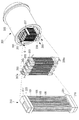
図1に示すようにSOFCモジュール201は、複数のSOFCカートリッジ203と、これら複数のSOFCカートリッジ203を収納する圧力容器205とを有する。また、SOFCモジュール201は、燃料ガス供給管207と複数の燃料ガス供給枝管207aとを有する。またSOFCモジュール201は、燃料ガス排出管209と複数の燃料ガス排出枝管209aとを有する。また、SOFCモジュール201は、酸化性ガス供給管(図示略)と酸化性ガス供給枝管(図示略)とを有する。また、SOFCモジュール201は、酸化性ガス排出管(図示略)と複数の酸化性ガス排出枝管(図示略)とを有する。
Hereinafter, the
As shown in FIG. 1, the
燃料ガス供給管207は、圧力容器205の外部に設けられ、SOFCモジュール201の発電量に対応して所定ガス組成と所定流量の燃料ガスを供給する燃料供給系(図示略)に接続されると共に、複数の燃料ガス供給枝管207aに接続されている。この燃料ガス供給管207は、燃料供給系(図示略)から供給される所定流量の燃料ガスを、複数の燃料ガス供給枝管207aに分岐して導く。
The fuel
燃料ガス供給枝管207aは、燃料ガス供給管207に接続されると共に、複数のSOFCカートリッジ203に接続されている。この燃料ガス供給枝管207aは、燃料ガス供給管207から供給される燃料ガスを複数のSOFCカートリッジ203に略均等の流量で導き、複数のSOFCカートリッジ203の発電性能を略均一化させるものである。
The fuel gas
燃料ガス排出枝管209aは、複数のSOFCカートリッジ203に接続されると共に、燃料ガス排出管209に接続されている。この燃料ガス排出枝管209aは、SOFCカートリッジ203から排出される排燃料ガスを燃料ガス排出管209に導くものである。また、燃料ガス排出管209は、複数の燃料ガス排出枝管209aに接続されると共に、一部が圧力容器205の外部に配置されている。この燃料ガス排出管209は、燃料ガス排出枝管209aから略均等の流量で導出される排燃料ガスを圧力容器205の外部の燃料ガス排出系(図示略)に導く。
The fuel gas
圧力容器205は、内部の圧力が0.1MPa〜約1MPa、内部の温度が大気温度〜約550℃で運用されるので、耐力性と酸化性ガス中に含まれる酸素などの酸化剤に対する耐食性を保有する材質が利用される。例えばSUS304などのステンレス系材が好適である。
Since the
SOFCカートリッジ203は、図2に示す通り、複数のセルスタック101と、発電室215と、燃料ガス供給室217と、燃料ガス排出室219と、酸化性ガス供給室221と、酸化性ガス排出室223とを有する。また、SOFCカートリッジ203は、上部管板225aと、下部管板225bと、上部断熱体227aと、下部断熱体227bとを有する。なお、本実施形態においては、SOFCカートリッジ203は、燃料ガス供給室217と燃料ガス排出室219と酸化性ガス供給室221と酸化性ガス排出室223とが図2のように配置されることで、燃料ガスと酸化性ガスとがセルスタック101の内側と外側とを対向して流れる構造となっているが、他の構造であっても良い。例えば、セルスタック101の内側と外側とを平行して流れる、または酸化性ガスがセルスタック101の長手方向と直交する方向へ流れるようにしても良い。
The
発電室215は、上部断熱体227aと下部断熱体227bとの間に形成された領域である。この発電室215は、セルスタック101の燃料電池セル105が配置され、燃料ガスと酸化性ガスとを電気化学的に反応させて発電を行う領域である。また、この発電室215のセルスタック101長手方向の中央部付近での温度は、SOFCモジュール201の定常運転時に、およそ700℃〜1100℃の高温雰囲気となる。
The
燃料ガス供給室217は、SOFCカートリッジ203の上部ケーシング229aと上部管板225aとに囲まれた領域である。また、燃料ガス供給室217は、上部ケーシング229aに備えられた燃料ガス供給孔231aによって、燃料ガス供給枝管207a(図示略)と連通されている。また、燃料ガス供給室217には、セルスタック101の一方の端部が、セルスタック101の基体管103の内部が燃料ガス排出室219に対して開放して配置されている。この燃料ガス供給室217は、燃料ガス供給枝管207a(図示略)から燃料ガス供給孔231aを介して供給される燃料ガスを、複数のセルスタック101の基体管103の内部に略均一流量で導き、複数のセルスタック101の発電性能を略均一化させる。
The fuel
燃料ガス排出室219は、SOFCカートリッジ203の下部ケーシング229bと下部管板225bとに囲まれた領域である。また、燃料ガス排出室219は、下部ケーシング229bに備えられた燃料ガス排出孔231bによって、燃料ガス排出枝管209a(図示略)と連通されている。また、燃料ガス排出室219には、セルスタック101の他方の端部が、セルスタック101の基体管103の内部が燃料ガス排出室219に対して開放して配置されている。この燃料ガス排出室219は、複数のセルスタック101の基体管103の内部を通過して燃料ガス排出室219に供給される排燃料ガスを集約して、燃料ガス排出孔231bを介して燃料ガス排出枝管209a(図示略)に導く。
The fuel
SOFCモジュール201の発電量に対応して所定ガス組成と所定流量の酸化性ガスを酸化性ガス供給枝管へと分岐して、複数のSOFCカートリッジ203へ供給する。酸化性ガス供給室221は、SOFCカートリッジ203の下部ケーシング229bと下部管板225bと下部断熱体227bとに囲まれた領域である。また、酸化性ガス供給室221は、下部ケーシング229bに備えられた酸化性ガス供給孔233aによって、酸化性ガス供給枝管(図示略)と連通されている。この酸化性ガス供給室221は、酸化性ガス供給枝管(図示略)から酸化性ガス供給孔233aを介して供給される所定流量の酸化性ガスを、後述する酸化性ガス供給隙間235aを介して発電室215に導く。
Corresponding to the power generation amount of the
酸化性ガス排出室223は、SOFCカートリッジ203の上部ケーシング229aと上部管板225aと上部断熱体227aとに囲まれた領域である。また、酸化性ガス排出室223は、上部ケーシング229aに備えられた酸化性ガス排出孔233bによって、酸化性ガス排出枝管(図示略)と連通されている。この酸化性ガス排出室223は、発電室215から、後述する酸化性ガス排出隙間235bを介して酸化性ガス排出室223に供給される排酸化性ガスを、酸化性ガス排出孔233bを介して酸化性ガス排出枝管(図示略)に導く。
The oxidizing
上部管板225aは、上部ケーシング229aの天板と上部断熱体227aとの間に、上部管板225aと上部ケーシング229aの天板と上部断熱体227aとが略平行になるように、上部ケーシング229aの側板に固定されている。また上部管板225aは、SOFCカートリッジ203に備えられるセルスタック101の本数に対応した複数の孔を有し、該孔にはセルスタック101が夫々挿入されている。この上部管板225aは、複数のセルスタック101の一方の端部をシール部材及び接着部材のいずれか一方又は両方を介して気密に支持すると共に、燃料ガス供給室217と酸化性ガス排出室223とを隔離する。
The
下部管板225bは、下部ケーシング229bの底板と下部断熱体227bとの間に、下部管板225bと下部ケーシング229bの底板と下部断熱体227bとが略平行になるように下部ケーシング229bの側板に固定されている。また下部管板225bは、SOFCカートリッジ203に備えられるセルスタック101の本数に対応した複数の孔を有し、該孔にはセルスタック101が夫々挿入されている。この下部管板225bは、複数のセルスタック101の他方の端部をシール部材及び接着部材のいずれか一方又は両方を介して気密に支持すると共に、燃料ガス排出室219と酸化性ガス供給室221とを隔離する。
The
上部断熱体227aは、上部ケーシング229aの下端部に、上部断熱体227aと上部ケーシング229aの天板と上部管板225aとが略平行になるように配置され、上部ケーシング229aの側板に固定されている。また、上部断熱体227aには、SOFCカートリッジ203に備えられるセルスタック101の本数に対応して、複数の孔が設けられている。この孔の直径はセルスタック101の外径よりも大きく設定されている。上部断熱体227aは、この孔の内面と、上部断熱体227aに挿通されたセルスタック101の外面との間に形成された酸化性ガス排出隙間235bを有する。
The
この上部断熱体227aは、発電室215と酸化性ガス排出室223とを仕切るものであり、上部管板225aの周囲の雰囲気が高温化し強度低下や酸化性ガス中に含まれる酸化剤による腐食が増加することを抑制する。上部管板225a等はインコネルなどの高温耐久性のある金属材料からなるが、上部管板225a等が発電室215内の高温に晒されて上部管板225a等との温度差が大きくなることで熱変形することを防ぐものである。また、上部断熱体227aは、発電室215を通過して高温に晒された排酸化性ガスを、酸化性ガス排出隙間235bを通過させて酸化性ガス排出室223に導くものである。
The
本実施形態によれば、上述したSOFCカートリッジ203の構造により、燃料ガスと酸化性ガスとがセルスタック101の内側と外側とを対向して流れるものとなっている。このことにより、排酸化性ガスは、基体管103の内部を通って発電室215に供給される燃料ガスとの間で熱交換がなされ、金属材料から成る上部管板225a等が座屈などの変形をしない温度に冷却されて酸化性ガス排出室223に供給される。また、燃料ガスは、発電室215から排出される排酸化性ガスとの熱交換により昇温され、発電室215に供給される。その結果、ヒータ等を用いることなく発電に適した温度に予熱昇温された燃料ガスを発電室215に供給することができる。
According to the present embodiment, the structure of the
下部断熱体227bは、下部ケーシング229bの上端部に、下部断熱体227bと下部ケーシング229bの底板と下部管板225bとが略平行になるように配置され、上部ケーシング229aの側板に固定されている。また、下部断熱体227bには、SOFCカートリッジ203に備えられるセルスタック101の本数に対応して、複数の孔が設けられている。この孔の直径はセルスタック101の外径よりも大きく設定されている。下部断熱体227bは、この孔の内面と、下部断熱体227bに挿通されたセルスタック101の外面との間に形成された酸化性ガス供給隙間235aを有する。
The
この下部断熱体227bは、発電室215と酸化性ガス供給室221とを仕切るものであり、下部管板225bの周囲の雰囲気が高温化し強度低下や酸化性ガス中に含まれる酸化剤による腐食が増加することを抑制する。下部管板225b等はインコネルなどの高温耐久性のある金属材料から成るが、下部管板225b等が高温に晒されて下部管板225b等内の温度差が大きくなることで熱変形することを防ぐものである。また、下部断熱体227bは、酸化性ガス供給室233に供給される酸化性ガスを、酸化性ガス供給隙間235aを通過させて発電室215に導くものである。
The
本実施形態によれば、上述したSOFCカートリッジ203の構造により、燃料ガスと酸化性ガスとがセルスタック101の内側と外側とを対向して流れるものとなっている。このことにより、基体管103の内部を通って発電室215を通過した排燃料ガスは、発電室215に供給される酸化性ガスとの間で熱交換がなされ、金属材料から成る下部管板225b等が座屈などの変形をしない温度に冷却されて燃料ガス排出室219に供給される。また、酸化性ガスは排燃料ガスとの熱交換により昇温され、発電室215に供給される。その結果、ヒータ等を用いることなく発電に必要な温度に昇温された酸化性ガスを発電室215に供給することができる。
According to the present embodiment, the structure of the
発電室215で発電された直流電力は、複数の燃料電池セル105に設けたNi/YSZ等からなるリード膜115によりセルスタック101の端部付近まで導出した後に、SOFCカートリッジ203の集電機構を介して集電して、各SOFCカートリッジ203の外部へと取り出される。集電機構によってSOFCカートリッジ203の外部に導出された電力は、各SOFCカートリッジ203の発電電力を所定の直列数および並列数へと相互に接続され、SOFCモジュール201の外部へと導出されて、インバータなどにより所定の交流電力へと変換されて、電力負荷へと供給される。直流電力を集電する集電機構の詳細については後述する。
The DC power generated in the
次に、図3を参照して本実施形態の円筒形セルスタックについて説明する。ここで、図3は、セルスタックの一態様を示す断面図である。
セルスタック101は、円筒形状の基体管103と、基体管103の外周面に複数形成された燃料電池セル105と、隣り合う燃料電池セル105の間に形成されたインターコネクタ107とを有する。燃料電池セル105は、燃料極109と固体電解質111と空気極113とが積層して形成されている。また、セルスタック101は、基体管103の外周面に形成された複数の燃料電池セル105の内、基体管103の軸方向において最も端に形成された燃料電池セル105の空気極113に、インターコネクタ107を介して電気的に接続されたリード膜115を有する。
Next, the cylindrical cell stack of this embodiment will be described with reference to FIG. Here, FIG. 3 is a cross-sectional view showing one mode of the cell stack.
The
基体管103は、多孔質材料からなり、例えば、CaO安定化ZrO2(CSZ)、又はY2O3安定化ZrO2(YSZ)、又はMgAl2O4とされる。この基体管103は、燃料電池セル105とインターコネクタ107とリード膜115とを支持すると共に、基体管103の内周面に供給される燃料ガスを基体管103の細孔を介して基体管103の外周面に形成される燃料極109に拡散させる。
The
燃料極109は、Niとジルコニア系電解質材料との複合材の酸化物で構成され、例えば、Ni/YSZが用いられる。この場合、燃料極109は、燃料極109の成分であるNiが燃料ガスに対して触媒作用を有する。この触媒作用は、基体管103を介して供給された燃料ガス、例えば、メタン(CH4)と水蒸気との混合ガスを反応させ、水素(H2)と一酸化炭素(CO)に改質するものである。また、燃料極109は、改質により得られる水素(H2)及び一酸化炭素(CO)と、固体電解質111を介して供給される酸素イオン(O2−)とを固体電解質111との界面付近において電気化学的に反応させて水(H2O)及び二酸化炭素(CO2)を生成するものである。なお、燃料電池セル105は、この時、酸素イオンから放出される電子によって発電する。
The
固体電解質111は、ガスを通しにくい気密性と、高温で高い酸素イオン導電性とを有するYSZが主として用いられる。この固体電解質111は、空気極で生成される酸素イオン(O2−)を燃料極に移動させるものである。
空気極113は、例えば、LaSrMnO3系酸化物、又はLaCoO3系酸化物で構成される。この空気極113は、固体電解質111との界面付近において、供給される空気等の酸化性ガス中の酸素を解離させて酸素イオン(O2−)を生成するものである。
The
The
インターコネクタ107は、SrTiO3系などのM1−xLxTiO3(Mはアルカリ土類金属元素、Lはランタノイド元素)で表される導電性ペロブスカイト型酸化物から構成され、燃料ガスと酸化性ガスとが混合しないように緻密な膜となっている。また、インターコネクタ107は、酸化雰囲気と還元雰囲気との両雰囲気下で安定した電気導電性を有する。
このインターコネクタ107は、隣り合う燃料電池セル105において、一方の燃料電池セル105の空気極113と他方の燃料電池セル105の燃料極109とを電気的に接続し、隣り合う燃料電池セル105同士を直列に接続するものである。
The
The
リード膜115は、電子伝導性を有すること、及びセルスタック101を構成する他の材料との熱膨張係数が近いことが必要であることから、Ni/YSZ等のNiとジルコニア系電解質材料との複合材で構成されている。このリード膜115は、インターコネクタにより直列に接続される複数の燃料電池セル105で発電された直流電力をセルスタック101の端部付近まで導出すものである。
Since the
次に、本実施形態のSOFCカートリッジ203の集電機構について、図4および図5を用いて説明する。
図4は、SOFCカートリッジ203を鉛直方向上方からみた平面図である。図4は、上部ケーシング229aを省略した図となっている。図5は、図4に示すSOFCカートリッジのB−B矢視断面図となっている。また、前述した図2に示す断面図は、図4に示すSOFCカートリッジ203のA−A矢視断面図となっている。
Next, the current collection mechanism of the
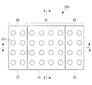
FIG. 4 is a plan view of the
図4および図5に示すように、SOFCカートリッジ203は、燃料電池を構成する円筒状の複数のセルスタック101を備える。各セルスタック101は、図3を用いて説明したように空気極113(正極)と燃料極109(負極)とを有する。
図4では1つのセルスタック101にのみ符号を付したが、32個の円形で示す全てがセルスタック101である。図5は、図4のB−B矢視断面図であるため、長編方向に配列された8本のセルスタック101が示されている。
As shown in FIGS. 4 and 5, the
In FIG. 4, only one
図5に示すように、複数のセルスタック101のそれぞれは、セルスタック101の中心軸が鉛直方向に延びかつ中心軸に直交する水平面内で隣接した状態で配置されるように、上部ケーシング229a(筐体)と下部ケーシング229b(筐体)によって支持されている。
As shown in FIG. 5, each of the plurality of cell stacks 101 is arranged such that the central axis of the
図4および図5に示すように、SOFCカートリッジ203は、空気極集電板11(第1正極集電部)と、空気極集電板12(第2正極集電部)と、空気極集電板13(第3正極集電部)と、燃料極集電板21(第1負極集電部)と、燃料極集電板22(第2負極集電部)と、燃料極集電板23(第3負極集電部)とを備える。
4 and 5, the
空気極集電板11,12,13は、それぞれ図4に示す水平面内の第1領域A1,第2領域A2,第3領域A3に配置される複数のセルスタック101(セルスタック群)の空気極113同士を電気的に接続する導電性の板状部材である。
燃料極集電板21,22,23は、それぞれ図4に示す水平面内の第1領域A1,第2領域A2,第3領域A3に配置される複数のセルスタック101(セルスタック群)の燃料極109同士を電気的に接続する導電性の板状部材である。
The air electrode
The anode
図4に示すように、複数のセルスタック101が配置される水平面内の配置領域は、長辺と短辺とを有する矩形状となっている。そして、図4に示す第1領域A1,第2領域A2,第3領域A3は、配置領域の長辺方向に分割された領域となっている。配置領域の長辺方向に分割しているのは、長辺方向に沿った温度分布が異なるからである。
As shown in FIG. 4, the arrangement region in the horizontal plane where the plurality of
図5に示すように、SOFCカートリッジ203内で電流を流通させる経路は、燃料極集電板21と燃料極集電板22とを電気的に分離して燃料極集電板21と空気極集電板12とを電気的に接続することにより形成されている。この経路は、第1領域A1のセルスタック101(第1セルスタック群)と第2領域A2のセルスタック101(第2セルスタック群)とが直列接続された経路である。
ここで、経路中に示す矢印は、経路を流れる電流の流通方向を示している。以下の各図においても、経路中に示す矢印は経路を流れる電流の流通方向を示すものとする。
As shown in FIG. 5, the path through which the current flows in the
Here, the arrow shown in the path | route has shown the distribution direction of the electric current which flows through a path | route. Also in the following figures, the arrows shown in the paths indicate the flow direction of the current flowing through the paths.
また、図5に示すように、SOFCカートリッジ203内で電流を流通させる経路は、燃料極集電板21と燃料極集電板23とを電気的に分離して燃料極集電板21と空気極集電板13とを電気的に接続することにより形成されている。この経路は、第1領域A1のセルスタック101(第1セルスタック群)と第3領域A3のセルスタック101(第3セルスタック群)とが直列接続された経路である。
Further, as shown in FIG. 5, the path through which the current flows in the
この経路において、燃料極集電板22と燃料極集電板23とが電気的に接続され、空気極集電板12と空気極集電板13とが電気的に接続されている。そのため、この経路は、領域A2のセルスタック101(第2セルスタック群)と領域A3のセルスタック101(第3セルスタック群)とが、並列接続された経路である。
In this path, the fuel electrode
本実施形態において、運転中(発電中)のSOFCカートリッジ203は、第1領域A1の温度が、第2領域A2の温度および第3領域A3の温度よりも高い。また、第2領域A2の温度および第3領域A3の温度は、略同じ温度となる。
SOFCカートリッジ203が有する複数のセルスタック101は、製造時のばらつきによる個体差はあるものの、いずれも同等の電流−電圧特性を有するものである。
In the present embodiment, the operating (power generation)
The plurality of
ここで、セルスタック101電流−電圧特性について図23を参照して説明する。セルスタック101は、内部を流通する電流値が大きくなるに連れて正極および負極の電位差を示す電圧値が低下するという電流−電圧特性を示す。また、この電流−電圧特性の関係は、セルスタック101の温度が高くなるほど図23中の右方へ移動する特性を有する。
本実施形態では、運転中(発電中)のSOFCカートリッジ203の内部において、第1領域A1の温度が、第2領域A2の温度および第3領域A3の温度よりも高い。また、第2領域A2の温度および第3領域A3の温度は、略同じ温度となる。そのため、第1領域A1に配置されるセルスタック101(第1セルスタック群)の電流−電圧特性は図23中に実線で示される。一方、第2領域A2,第3領域A3に配置されるセルスタック101(第2セルスタック群および第3セルスタック群)の電流−電圧特性は図23中に破線で示される。
Here, the current-voltage characteristics of the
In the present embodiment, the temperature of the first region A1 is higher than the temperature of the second region A2 and the temperature of the third region A3 inside the
次に、本実施形態のSOFCカートリッジ203と比較例のSOFCカートリッジ203’とを比較した結果について説明する。
図21,図22は、比較例のSOFCカートリッジ203’を示す図である。
図21,図22に示すように、比較例のSOFCカートリッジ203’は、第1領域A1,第2領域A2,第3領域A3の全領域のセルスタック101の燃料極109が、単一の燃料極集電板21’によって電気的に接続されている。また、比較例のSOFCカートリッジ203’は、第1領域A1,第2領域A2,第3領域A3の全領域のセルスタック101の空気極113が、単一の空気極集電板11’によって電気的に接続されている。そのため、SOFCカートリッジ203’に形成される経路は、セルスタック101の全てを並列接続した経路となっている。
比較例において、運転中(発電中)のSOFCカートリッジ203’は、第1領域A1の温度が、第2領域A2の温度および第3領域A3の温度よりも高い。また、第2領域A2の温度および第3領域A3の温度は、略同じ温度となる。
Next, a result of comparison between the
21 and 22 are views showing a
As shown in FIGS. 21 and 22, the
In the comparative example, the operating (power generation)
比較例のSOFCカートリッジ203’は、全てのセルスタック101を並列接続する経路を形成するため、SOFCカートリッジ203’の経路の入力端と出力端の電圧差は、一定のV2となっている(図23参照。)。図23に示すように、第1領域A1と、第2領域A2および第3領域A3の電流−電圧特性は異なっている。そのため、第1領域A1に配置されるセルスタック101を流れる電流値がI’1であるのに対し、第2領域A2および第3領域A3に配置されるセルスタック101を流れる電流値がI’2となっている。
Since the
一方、本実施形態のSOFCカートリッジ203は、第1領域A1に配置されるセルスタック101を電流が通過する経路と、第2領域A2および第3領域A3に配置されるセルスタック101を電流が通過する経路とが、直列接続されている。
第1領域A1に配置されるセルスタック101を電流が通過する経路の電流−電圧特性は、図23に実線で示すものであるが、この経路を通過する電流値I2は比較例の電流値I’2よりも低くなっている。これは、燃料極集電板21と燃料極集電板22が電気的に分離しており、電気抵抗値の低い第1領域A1のセルスタック101への電流の流れ込みが抑制されるからである。
On the other hand, in the
A current-voltage characteristic of a path through which a current passes through the
また、第2領域A2および第3領域A3に配置されるセルスタック101を電流が通過する経路の電流−電圧特性は、図23に破線で示すものであるが、この経路を通過する電流値I1は比較例の電流値I’1よりも高くなっている。これも、燃料極集電板21と燃料極集電板22が電気的に分離しており、電気抵抗値の低い第1領域A1のセルスタック101への電流の流れ込みが抑制されるからである。
Further, the current-voltage characteristic of the path through which the current passes through the
図23に示すように、比較例のSOFCカートリッジ203’よりも本実施形態のSOFCカートリッジ203の方が、運転中の温度が相対的に高い第1領域A1のセルスタック101に流れる電流の大きさと運転中の温度が相対的に低い第2領域A2および第3領域A3のセルスタック101に流れる電流の大きさとの差分が小さくなる。
As shown in FIG. 23, the
以上説明した本実施形態のSOFCカートリッジ203が奏する作用および効果について説明する。
本実施形態のSOFCカートリッジ203によれば、運転中において、第1領域A1の温度が第2領域A2の温度よりも高いため、第1領域A1に配置されるセルスタック101の電気抵抗値は第2領域A2に配置されるセルスタック101の電気抵抗値よりも低くなる。本実施形態のSOFCカートリッジ203によれば、燃料極集電板21と燃料極集電板22とが電気的に分離されるため、これらが電気的に接続される場合に比べ、燃料極集電板21に流れる電流の大きさと燃料極集電板22に流れる電流の大きさとに大きな偏りが生じることが抑制される。
The operation and effect of the
According to the
また、本実施形態のSOFCカートリッジ203によれば、燃料極集電板21と空気極集電板12とが電気的に接続されて、第1領域A1に配置されるセルスタック101と第2領域A2に配置されるセルスタック101とが直列接続される。そのため、第1領域A1に配置されるセルスタック101が出力する電力と、第2領域A2に配置されるセルスタック101が出力する電力とを合計した電力が出力される。よって、水平面内の全領域の複数のセルスタック101を並列に接続する比較例のSOFCカートリッジ203’と同様の電力を得ることができる。
Further, according to the
また、本実施形態のSOFCカートリッジ203によれば、運転中において、第1領域A1の温度が第3領域A3の温度よりも高いため、第1領域A1に配置されるセルスタック101の電気抵抗値は第3領域A3に配置されるセルスタック101の電気抵抗値よりも低くなる。本実施形態のSOFCカートリッジ203によれば、燃料極集電板21と燃料極集電板23とが電気的に分離されるため、これらが電気的に接続される場合に比べ、燃料極集電板21に流れる電流の大きさと燃料極集電板23に流れる電流の大きさとに大きな偏りが生じることが抑制される。
Further, according to the
また、本実施形態のSOFCカートリッジ203によれば、燃料極集電板21と空気極集電板13とが電気的に接続され、かつ燃料極集電板22と燃料極集電板23とが電気的に接続されて、第2領域A2のセルスタック101と第3領域A3のセルスタック101とが並列接続される。運転中に第1領域A1よりも低温な第2領域A2と第3領域A3に配置されるセルスタック101同士の並列接続であるため、第2領域A2のセルスタック101と第3領域A3のセルスタック101に流れる電流の大きさが第1領域A1のセルスタック101に流れる電流の大きさから大きく偏ることが抑制される。
Further, according to the
本実施形態のSOFCカートリッジ203においては、複数のセルスタック101が配置される水平面内の配置領域は、長辺と短辺とを有する矩形状であり、第1領域A1,第2領域A2,第3領域A3は、配置領域の長辺方向に分割された領域である。
このようにすることで、配置領域の長辺方向に沿って運転中の温度勾配があるSOFCカートリッジ203において、相対的に高温な第1領域A1の燃料極集電板21と相対的に低温な第2領域A2の燃料極集電板22とが電気的に分離される。そのため、これらが電気的に接続される場合に比べ、燃料極集電板21に流れる電流の大きさと燃料極集電板22に流れる電流の大きさとに大きな偏りが生じることが抑制される。
In the
In this way, in the
〔第2実施形態〕
次に、本発明の第2実施形態について図6および図7を参照して説明する。
第2実施形態は第1実施形態の変形例であり、以下で特に説明する場合を除き第1実施形態と同様であるものとする。
第1実施形態のSOFCカートリッジ203は、セルスタック101が配置される水平面上の領域を長辺方向に3つの領域に分割するものであった。それに対して第2実施形態のSOFCカートリッジ203は、セルスタック101が配置される水平面上の領域を長辺方向に2つの領域に分割するものである。
[Second Embodiment]
Next, a second embodiment of the present invention will be described with reference to FIGS.
The second embodiment is a modification of the first embodiment, and is the same as the first embodiment unless otherwise described below.
The
図6に示すように本実施形態のSOFCカートリッジ203は、セルスタック101が配置される水平面上の全領域を長辺方向に第1領域A1と第2領域A2とに分割している。
図6および図7に示すように、SOFCカートリッジ203は、空気極集電板311(第1正極集電部)と、空気極集電板312(第2正極集電部)と、燃料極集電板321(第1負極集電部)と、燃料極集電板322(第2負極集電部)とを備える。
As shown in FIG. 6, the
As shown in FIGS. 6 and 7, the
空気極集電板311,312は、それぞれ図6に示す水平面内の第1領域A1,第2領域A2に配置される複数のセルスタック101(セルスタック群)の空気極113同士を電気的に接続する導電性の板状部材である。
燃料極集電板321,322は、それぞれ図6に示す水平面内の第1領域A1,第2領域A2に配置される複数のセルスタック101(セルスタック群)の燃料極109同士を電気的に接続する導電性の板状部材である。
The air electrode
The anode
図6に示すように、複数のセルスタック101が配置される水平面内の配置領域は、長辺と短辺とを有する矩形状となっている。そして、図6に示す第1領域A1,第2領域A2は、配置領域を長辺方向に分割した領域となっている。配置領域を長辺方向に分割しているのは、本実施形態において運転中のSOFCカートリッジ203の長辺方向に沿った温度分布が異なるからである。
As shown in FIG. 6, the arrangement area in the horizontal plane where the plurality of
図7に示すように、SOFCカートリッジ203内で電流を流通させる経路は、燃料極集電板321と燃料極集電板322とを電気的に分離して燃料極集電板321と空気極集電板312とを電気的に接続することにより形成されている。この経路は、第1領域A1のセルスタック101(第1セルスタック群)と第2領域A2のセルスタック101(第2セルスタック群)とが直列接続された経路である。
本実施形態において、運転中(発電中)のSOFCカートリッジ203は、第1領域A1の温度が、第2領域A2の温度よりも高い。
As shown in FIG. 7, the current flow path in the
In the present embodiment, the temperature of the first area A1 of the operating (power generation)
本実施形態のSOFCカートリッジ203によれば、燃料極集電板321と燃料極集電板322とが電気的に分離されるため、これらが電気的に接続される場合に比べ、燃料極集電板321に流れる電流の大きさと燃料極集電板322に流れる電流の大きさとに大きな偏りが生じることが抑制される。
According to the
また、本実施形態のSOFCカートリッジ203によれば、燃料極集電板321と空気極集電板312とが電気的に接続されて、第1領域A1に配置されるセルスタック101と第2領域A2に配置されるセルスタック101とが直列接続される。そのため、第1領域A1に配置されるセルスタック101が出力する電力と、第2領域A2に配置されるセルスタック101が出力する電力とを合計した電力が出力される。
本実施形態のSOFCカートリッジ203は、複数のセルスタック101が配置される水平面内の配置領域が、長辺方向に沿って、相対的に高温な第1領域A1と相対的に低温な第2領域A2とを有するような場合に特に有効である。
Further, according to the
In the
なお、以上の説明においては、複数のセルスタック101が配置される水平面内の配置領域を長辺方向に沿って2分割するものであったが、これを4分割するように変形してもよい。この変形例の場合、図8に示すように、複数のセルスタック101が配置される水平面内の配置領域が、長辺方向に沿って第1領域A1,第2領域A2,第3領域A3,第4領域A4に4分割される。
In the above description, the arrangement area in the horizontal plane in which the plurality of
図8および図9に示すように、SOFCカートリッジ203は、空気極集電板411(第1正極集電部)と、空気極集電板412(第2正極集電部)と、空気極集電板413(第3正極集電部)と、空気極集電板414(第4正極集電部)と、燃料極集電板421(第1負極集電部)と、燃料極集電板422(第2負極集電部)と、燃料極集電板423(第3負極集電部)と、燃料極集電板424(第4負極集電部)とを備える。そして、第1領域A1のセルスタック101と、第2領域A2のセルスタック101と、第3領域A3のセルスタック101と、第4領域A4のセルスタック101とが、直列接続された経路が形成される。
As shown in FIGS. 8 and 9, the
図8および図9に示すSOFCカートリッジ203では、運転中(発電中)の各領域の温度が、第4領域A4,第3領域A3,第2領域A2,第1領域A1のように徐々に高くなっている。図8および図9に示すSOFCカートリッジ203は、長辺方向の温度分布の勾配が大きくなる場合に特に有利である。
In the
〔第3実施形態〕
次に、本発明の第3実施形態について図10および図11を参照して説明する。
第3実施形態は第2実施形態の変形例であり、以下で特に説明する場合を除き第2実施形態と同様であるものとする。
第2実施形態のSOFCカートリッジ203は、セルスタック101が配置される水平面上の領域を長辺方向に2つの領域に分割するものであった。それに対して第3実施形態のSOFCカートリッジ203は、セルスタック101が配置される水平面上の領域を中央部分の第1領域A1と周辺部分の第2領域A2とに分割するものである。
[Third Embodiment]
Next, a third embodiment of the present invention will be described with reference to FIGS.
The third embodiment is a modification of the second embodiment, and is the same as the second embodiment unless otherwise described below.
In the
図10に示すように本実施形態のSOFCカートリッジ203は、セルスタック101が配置される水平面上の全領域を長辺方向の中央部分と短辺方向の中央部分とを含む第1領域A1と、第1領域A1の周辺を取り囲む第2領域A2とに分割している。
図10および図11に示すように、SOFCカートリッジ203は、空気極集電板511(第1正極集電部)と、空気極集電板512(第2正極集電部)と、燃料極集電板521(第1負極集電部)と、燃料極集電板522(第2負極集電部)とを備える。
As shown in FIG. 10, the
As shown in FIGS. 10 and 11, the
空気極集電板511,512は、それぞれ図10に示す水平面内の第1領域A1,第2領域A2に配置される複数のセルスタック101(セルスタック群)の空気極113同士を電気的に接続する導電性の板状部材である。
燃料極集電板521,522は、それぞれ図10に示す水平面内の第1領域A1,第2領域A2に配置される複数のセルスタック101(セルスタック群)の燃料極109同士を電気的に接続する導電性の板状部材である。
The air electrode
The fuel electrode
図10に示すように、複数のセルスタック101が配置される水平面内の配置領域は、長辺と短辺とを有する矩形状となっている。そして、図10に示す第1領域A1,第2領域A2は、長辺方向の中央部分と短辺方向の中央部分とを含む領域と、その周辺を取り囲む領域とに分割されている。配置領域を中央部分とその周辺部分とに分割しているのは、本実施形態において運転中のSOFCカートリッジ203の中央部分と周辺部分とで温度分布が異なるからである。
As shown in FIG. 10, the arrangement region in the horizontal plane where the plurality of
図11に示すように、SOFCカートリッジ203内で電流を流通させる経路は、燃料極集電板521と燃料極集電板522とを電気的に分離して燃料極集電板521と空気極集電板512とを電気的に接続することにより形成されている。この経路は、第1領域A1のセルスタック101(第1セルスタック群)と第2領域A2のセルスタック101(第2セルスタック群)とが直列接続された経路である。
本実施形態において、運転中(発電中)のSOFCカートリッジ203は、第1領域A1の温度が、第2領域A2の温度よりも高い。
As shown in FIG. 11, the current flow path in the
In the present embodiment, the temperature of the first area A1 of the operating (power generation)
本実施形態のSOFCカートリッジ203によれば、燃料極集電板521と燃料極集電板522とが電気的に分離されるため、これらが電気的に接続される場合に比べ、燃料極集電板521に流れる電流の大きさと燃料極集電板522に流れる電流の大きさとに大きな偏りが生じることが抑制される。
According to the
また、本実施形態のSOFCカートリッジ203によれば、燃料極集電板521と空気極集電板512とが電気的に接続されて、第1領域A1に配置されるセルスタック101と第2領域A2に配置されるセルスタック101とが直列接続される。そのため、第1領域A1に配置されるセルスタック101が出力する電力と、第2領域A2に配置されるセルスタック101が出力する電力とを合計した電力が出力される。
本実施形態のSOFCカートリッジ203は、複数のセルスタック101が配置される水平面内の配置領域が、相対的に高温な第1領域A1を中央部分に有し、相対的に低温な第2領域A2をその周辺部分に有するような場合に特に有効である。
Further, according to the
In the
なお、以上の説明においては、複数のセルスタック101が配置される水平面内の配置領域を中央部分の第1領域A1と周辺部分の第2領域A2とに分割するものであったが、各領域を更に2分割するように変形してもよい。この変形例の場合、図12に示すように、複数のセルスタック101が配置される水平面内の配置領域が、長手方向の中央部かつ短手方向の中央部に配置される第1領域A1,第2領域A2と、それらの周辺部に配置される第3領域A3,第4領域A4とに4分割される。
In the above description, the arrangement area in the horizontal plane where the plurality of
図12および図13に示すように、SOFCカートリッジ203は、空気極集電板611(第1正極集電部)と、空気極集電板612(第2正極集電部)と、空気極集電板613(第3正極集電部)と、空気極集電板614(第4正極集電部)と、燃料極集電板621(第1負極集電部)と、燃料極集電板622(第2負極集電部)と、燃料極集電板623(第3負極集電部)と、燃料極集電板624(第4負極集電部)とを備える。そして、第1領域A1のセルスタック101と、第2領域A2のセルスタック101と、第3領域A3のセルスタック101と、第4領域A4のセルスタック101とが、直列接続された経路が形成される。
As shown in FIGS. 12 and 13, the
図12および図13に示すSOFCカートリッジ203では、運転中(発電中)の各領域の温度が、第4領域A4,第3領域A3,第2領域A2,第1領域A1のように徐々に高くなっている。図12および図13に示すSOFCカートリッジ203は、長辺方向に沿って温度が異なり、かつ周辺部分と中央部分とで温度が異なる場合に特に有利である。
In the
〔第4実施形態〕
次に、本発明の第4実施形態について図14を参照して説明する。
第4実施形態は第2実施形態の変形例であり、以下で特に説明する場合を除き第2実施形態と同様であるものとする。
第4実施形態のSOFCカートリッジ203は、セルスタック101が配置される水平面上の領域を長辺方向に2つの領域に分割する際に、各領域に配置するセルスタック101の本数を同一とするものであった。それに対して本実施形態は、セルスタック101が配置される水平面上の領域を長辺方向に2つの領域に分割する際に、各領域に配置するセルスタック101の本数を異ならせるものである。
[Fourth Embodiment]
Next, a fourth embodiment of the present invention will be described with reference to FIG.
The fourth embodiment is a modification of the second embodiment, and is the same as the second embodiment unless otherwise described below.
In the
図6に示す第2実施形態のSOFCカートリッジ203は、第1領域A1に配置するセルスタック101の本数と、第2領域A2に配置するセルスタック101の本数とをそれぞれ16本と同一にするものであった。
この場合、温度に依存する電気抵抗値の差によって、相対的に高温な第1領域A1に流れる電流の大きさが、相対的に低温な第2領域A2に流れる電流の大きさよりも大きくなる。そのため、セルスタック101の1本当たりに流れる電流の大きさが、第1領域A1に配置されるセルスタック101の方が第2領域A2に配置されるセルスタック101よりも大きくなる。
The
In this case, the magnitude of the current flowing in the relatively high temperature first area A1 becomes larger than the magnitude of the current flowing in the relatively low temperature second area A2 due to the difference in temperature-dependent electrical resistance value. Therefore, the magnitude of the current flowing per
一方、図14に示す本実施形態のSOFCカートリッジ203は、第1領域A1に配置するセルスタック101の本数を20本とし、第2領域A2に配置するセルスタック101の本数とをそれぞれ12本とするものである。ここで、本実施形態のSOFCカートリッジ203は、運転中に第1領域A1の温度が第2領域A2よりも高温になる。
この場合、第2実施形態のSOFCカートリッジ203に比べ、相対的に高温な第1領域A1のセルスタック101の1本当たりに流れる電流の大きさが小さくなる。
この場合、相対的に高温な第1領域A1のセルスタック101の1本当たりに流れる電流の大きさと、相対的に低温な第2領域A2のセルスタック101の1本当たりに流れる電流の大きさと差を小さくすることができる。
On the other hand, the
In this case, compared to the
In this case, the magnitude of the current that flows per
本実施形態のSOFCカートリッジ203によれば、第1領域A1に配置されるセルスタック101の本数と第2領域A2に配置されるセルスタック10の本数を同一にする場合に比べ、第1領域A1に配置される各セルスタック101に分配される電流の大きさが小さくなるとともに第2領域A2に配置される各セルスタック101に分配される電流の大きさが大きくなる。したがって、第1領域A1の燃料極集電板に流れる電流の大きさと第2領域A2の燃料極集電板に流れる電流の大きさとに偏りが生じることが更に抑制される。
According to the
〔第5実施形態〕
次に、本発明の第5実施形態について図15および図16を参照して説明する。
第5実施形態は第1実施形態の変形例であり、以下で特に説明する場合を除き第1実施形態と同様であるものとする。
第1実施形態は、セルスタック101が配置される配置領域を、相対的に高温な第1領域A1と、相対的に低温な第2領域A2および第3領域A3とに分割し、第2領域A2および第3領域A3とに配置されるセルスタック101を並列接続するものであった。
それに対して本実施形態は、第1実施形態における第1領域A1を更に2分割するとともに、第1実施形態における第2領域A2および第3領域A3とが単独で並列接続されないようにしたものである。
[Fifth Embodiment]
Next, a fifth embodiment of the present invention will be described with reference to FIGS. 15 and 16.
The fifth embodiment is a modification of the first embodiment, and is the same as the first embodiment unless otherwise described below.
In the first embodiment, the arrangement region in which the
On the other hand, the present embodiment further divides the first region A1 in the first embodiment into two and prevents the second region A2 and the third region A3 in the first embodiment from being independently connected in parallel. is there.
図15および図16に示すように、SOFCカートリッジ203は、空気極集電板711(第1正極集電部)と、空気極集電板712(第2正極集電部)と、空気極集電板713(第3正極集電部)と、空気極集電板714(第4正極集電部)と、燃料極集電板721(第1負極集電部)と、燃料極集電板722(第2負極集電部)と、燃料極集電板723(第3負極集電部)と、燃料極集電板724(第4負極集電部)とを備える。
As shown in FIGS. 15 and 16, the
本実施形態のSOFCカートリッジ203においては、第1領域A1のセルスタック101と、第2領域A2のセルスタック101とが、直列接続された第1経路が形成される。また、第3領域A3のセルスタック101と、第4領域A4のセルスタック101とが、直列接続された第2経路が形成される。
また、燃料極集電板721と燃料極集電板724とを電気的に接続し、空気極集電板712と空気極集電板713とを電気的に接続することにより、第1経路と第2経路とを並列接続した経路が形成される。
In the
Further, by electrically connecting the fuel electrode
本実施形態のSOFCカートリッジ203によれば、運転中の第1領域A1の温度が第2領域A2の温度よりも高い。そのため、第1領域A1に配置されるセルスタック101の電気抵抗値は第2領域2に配置されるセルスタック101の電気抵抗値よりも低くなる。本実施形態のSOFCカートリッジ203によれば、燃料極集電板721と燃料極集電板722とが電気的に分離されるため、これらが電気的に接続される場合に比べ、燃料極集電板721に流れる電流の大きさと燃料極集電板722に流れる電流の大きさとに大きな偏りが生じることが抑制される。
According to the
本実施形態のSOFCカートリッジ203によれば、運転中の第3領域A3の温度が第4領域A4の温度よりも高い。そのため、第3領域A3に配置されるセルスタック101の電気抵抗値は第4領域A4に配置されるセルスタック101の電気抵抗値よりも低くなる。本実施形態のSOFCカートリッジ203によれば、燃料極集電板723と燃料極集電板724とが電気的に分離されるため、これらが電気的に接続される場合に比べ、燃料極集電板723に流れる電流の大きさと燃料極集電板724に流れる電流の大きさとに大きな偏りが生じることが抑制される。
According to the
本実施形態のSOFCカートリッジ203によれば、第1領域A1に配置されるセルスタック101と第2領域に配置されるセルスタック101とを直列接続した第1経路と第3領域A3に配置されるセルスタック101と第4領域A4に配置されるセルスタック101とを直列接続した第2経路とを並列接続した経路とが形成される。運転中の第2領域A2と第3領域A3の温度差が少ない場合、第1領域A1の温度が第4領域A4の温度よりも高い状態となる。この場合、第1領域A1に配置されるセルスタック101の電気抵抗値が低くなり、第4領域A4に配置されるセルスタック101の電気抵抗値が高くなる。
According to the
本実施形態では、第1領域A1に配置されるセルスタック101と第2領域A2に配置されるセルスタック101とを直列接続して第1経路を形成し、第3領域A3に配置されるセルスタック101と第4領域A4に配置されるセルスタック101とを直列接続して第2経路を形成している。各経路の電気抵抗値は直列接続による合成抵抗値となるため、第2領域A2に配置されるセルスタック101と第4領域A4に配置されるセルスタック101の電気抵抗値に差があったとしても、第1経路の電気抵抗値と第2経路の電気抵抗値とに大きな差が生じることが抑制される。
In the present embodiment, the
〔第6実施形態〕
次に、本発明の第6実施形態について図17および図18を参照して説明する。
第6実施形態は第5実施形態の変形例であり、以下で特に説明する場合を除き第5実施形態と同様であるものとする。
第5実施形態は隣接する領域のセルスタック群同士を直列接続して第1経路と第2経路とを形成し、第1経路と第2経路とを並列接続するものであった。
それに対して第6実施形態は、隣接しない領域のセルスタック群同士を直列接続して第1経路と第2経路とを形成し、第1経路と第2経路とを並列接続するものである。
[Sixth Embodiment]
Next, a sixth embodiment of the present invention will be described with reference to FIGS.
The sixth embodiment is a modification of the fifth embodiment, and is the same as the fifth embodiment unless otherwise described below.
In the fifth embodiment, cell stack groups in adjacent regions are connected in series to form a first path and a second path, and the first path and the second path are connected in parallel.
On the other hand, in the sixth embodiment, cell stack groups in non-adjacent areas are connected in series to form a first path and a second path, and the first path and the second path are connected in parallel.
第5実施形態のSOFCカートリッジ203は、長辺方向に沿って4分割した領域のうち中央に位置する2つの領域の温度差が少なく、両端に位置する2つの領域の温度差が大きいものであった。
それに対して第6実施形態のSOFCカートリッジ203は、運転中の温度が長辺方向に沿って徐々に温度が高くなる温度分布となっている。具体的には、図17に示す第4領域A4,第2領域A2,第3領域A3,第1領域A1の順に徐々に温度が高くなる温度分布となっている。
The
In contrast, the
図17および図18に示すように、SOFCカートリッジ203は、空気極集電板811(第1正極集電部)と、空気極集電板812(第2正極集電部)と、空気極集電板813(第3正極集電部)と、空気極集電板814(第4正極集電部)と、燃料極集電板821(第1負極集電部)と、燃料極集電板822(第2負極集電部)と、燃料極集電板823(第3負極集電部)と、燃料極集電板824(第4負極集電部)とを備える。
As shown in FIGS. 17 and 18, the
本実施形態のSOFCカートリッジ203においては、第1領域A1のセルスタック101と第2領域A2のセルスタック101とが直列接続された第1経路が形成される。また、第3領域A3のセルスタック101と第4領域A4のセルスタック101とが直列接続された第2経路が形成される。
また、燃料極集電板821と燃料極集電板824とを電気的に接続し、空気極集電板812と空気極集電板813とを電気的に接続することにより、第1経路と第2経路とを並列接続した経路が形成される。
In the
Further, by electrically connecting the fuel electrode
本実施形態のSOFCカートリッジ203においては、運転中の第3領域A3の温度が第2領域A2の温度よりも高くなっている。そのため、第1から第4領域のうち相対的に温度の高い第1領域A1と第3領域A3のセルスタック群同士を直列接続し、相対的に温度の低い第2領域A2と第4領域A4のセルスタック群同士を直列接続する場合に比べ、第1経路の電気抵抗値と第2経路の電気抵抗値の差が少なくなる。これにより、並列接続される第1経路と第2経路とを通過する電流の大きさに大きな偏りが生じることが抑制される。
In the
〔第7実施形態〕
次に、本発明の第7実施形態について図19を参照して説明する。
第7実施形態は第5実施形態の変形例であり、以下で特に説明する場合を除き第5実施形態と同様であるものとする。
第5実施形態は単一のSOFCカートリッジ203内の隣接する領域のセルスタック群同士を直列接続して第1経路と第2経路とを形成するものであった。
それに対して第7実施形態は、隣接して配置される2つのSOFCカートリッジ203a,203bの隣接するセルスタック群同士を直列接続して第1経路と第2経路とを形成するものである。
SOFCカートリッジ203a,203bの構造については、第1実施形態で説明したSOFCカートリッジ203と同様であるため、説明を省略する。
[Seventh Embodiment]
Next, a seventh embodiment of the present invention will be described with reference to FIG.
The seventh embodiment is a modification of the fifth embodiment, and is the same as the fifth embodiment unless otherwise described below.
In the fifth embodiment, cell stack groups in adjacent areas in a
In contrast, in the seventh embodiment, adjacent cell stack groups of two
The structure of the
第5実施形態のSOFCカートリッジ203は、長辺方向に沿って4分割した領域のうち中央に位置する2つの領域の温度差が少なく、両端に位置する2つの領域の温度差が大きいものであった。
それに対して第7実施形態のSOFCカートリッジ203a,203bは、運転中の温度が長辺方向に沿って徐々に温度が高くなる温度分布となっている。具体的には、SOFCカートリッジ203の運転中の温度が、図19に示す第4領域A4,第2領域A2,第3領域A3,第1領域A1の順に徐々に温度が高くなる温度分布となっている。
The
In contrast, the
図19に示すように、本実施形態のSOFCモジュール201(燃料電池システム)は、SOFCカートリッジ203a(第1燃料電池装置)とSOFCカートリッジ203b(第2燃料電池装置)とを有する。
SOFCカートリッジ203aは、空気極集電板911(第1正極集電部)と、空気極集電板912と、空気極集電板913と、空気極集電板914(第2正極集電部)と、燃料極集電板921(第1負極集電部)と、燃料極集電板922と、燃料極集電板923と、燃料極集電板924(第2負極集電部)とを備える。
SOFCカートリッジ203bは、空気極集電板1011(第3正極集電部)と、空気極集電板1012と、空気極集電板1013と、空気極集電板1014(第4正極集電部)と、燃料極集電板1021(第3負極集電部)と、燃料極集電板1022と、燃料極集電板1023と、燃料極集電板1024(第4負極集電部)とを備える。
As shown in FIG. 19, the SOFC module 201 (fuel cell system) of this embodiment includes an
The
The
本実施形態のSOFCモジュール201においては、SOFCカートリッジ203aの第1領域A1のセルスタック101とSOFCカートリッジ203bの第1領域A1(第1領域)のセルスタック101とが直列接続された経路(第1経路)が形成される。また、SOFCカートリッジ203aの第4領域A4(第2領域)のセルスタック101とSOFCカートリッジ203bの第4領域A4のセルスタック101とが直列接続された経路(第2経路)が形成される。
同様に、SOFCモジュール201においては、SOFCカートリッジ203aの第2領域A2のセルスタック101とSOFCカートリッジ203bの第2領域A2のセルスタック101とが直列接続された経路が形成される。また、SOFCカートリッジ203aの第3領域A3のセルスタック101とSOFCカートリッジ203bの第3領域A3のセルスタック101とが直列接続された経路が形成される。
In the
Similarly, in the
図19に示すように、本実施形態のSOFCモジュール201においては、第1領域A1に配置される燃料極集電板921と、第4領域A4に配置される燃料極集電板924とを電気的に分離して空気極集電板911と燃料極集電板1021とを電気的に接続している。これにより、SOFCカートリッジ203aの第1領域A1のセルスタック101(第1セルスタック群)とSOFCカートリッジ203bの第1領域A1のセルスタック101(第3セルスタック群)とが直列接続された経路(第1経路)が形成される。
As shown in FIG. 19, in the
また、本実施形態のSOFCモジュール201においては、第4領域A4に配置される燃料極集電板924と、第1領域A1に配置される燃料極集電板921とを電気的に分離して空気極集電板914と燃料極集電板1024とを電気的に接続している。これにより、SOFCカートリッジ203aの第4領域A4のセルスタック101(第2セルスタック群)とSOFCカートリッジ203bの第4領域A4のセルスタック101(第4セルスタック群)とが直列接続された経路(第2経路)が形成される。
In the
第2領域A2,第3領域A3についても、第1領域A1,第4領域A4と同様に直列接続された経路が形成される。
図19に示すように、第1領域A1,第2領域A2,第3領域A3,第4領域A4に形成される各経路の終端には、チョッパ回路2a,2b,2c,2dが接続されている。各チョッパ回路は、制御部(図示略)からの指示によって、各経路からインバータ回路3へ流入する電流の大きさを調整できるようになっている。
Also in the second region A2 and the third region A3, paths connected in series are formed as in the first region A1 and the fourth region A4.
As shown in FIG. 19,
本実施形態においては、SOFCカートリッジ203a,203bのそれぞれにおいて、第4領域A4,第2領域A2,第3領域A3,第1領域A1の順に徐々に運転中の温度が高くなる温度分布となっている。そのため、何らの調整もしない場合、各領域に流れる電流の大きさは第4領域A4,第2領域A2,第3領域A3,第1領域A1の順に徐々に大きくなる。本実施形態のチョッパ回路は、このような場合に、第1領域A1の経路に対して流れる電流に対して相対的に電流の大きさが小さくなる他の領域の経路の電流の大きさが大きくなるように調整するものである。
In the present embodiment, in each of the
以上説明したように、本実施形態のSOFCモジュール201によれば、SOFCカートリッジ203aの第1領域A1のセルスタック101とSOFCカートリッジ203bの第1領域A1のセルスタック101とが直列接続された経路(第1経路)が形成される。また、SOFCカートリッジ203aの第4領域A4のセルスタック101とSOFCカートリッジ203bのセルスタック101とが直列接続された経路(第2経路)が形成される。
運転中の第1領域A1の温度が第4領域A4の温度よりも高いため、第1領域A1に配置されるセルスタック101の電気抵抗値は第4領域A4に配置されるセルスタック101の電気抵抗値よりも低くなる。
本実施形態のSOFCモジュール201によれば、燃料極集電板921と燃料極集電板922とが電気的に分離されるため、これらが電気的に接続される場合に比べ、燃料極集電板921に流れる電流の大きさと燃料極集電板922に流れる電流の大きさとに大きな偏りが生じることが抑制される。
また、第1領域A1に形成される経路と他の領域に形成される経路とが独立して形成されるため、第1領域A1に比べて相対的に温度の低い第2領域A2,第3領域A3,第4領域A4に配置されるセルスタック101が形成する経路に流れる電流の大きさを大きくするように制御することができる。これにより、SOFCモジュール201全体の出力を増加させることが可能となる。
As described above, according to the
Since the temperature of the first region A1 during operation is higher than the temperature of the fourth region A4, the electric resistance value of the
According to the
In addition, since the path formed in the first area A1 and the path formed in other areas are formed independently, the second area A2, the third area having a relatively lower temperature than the first area A1. It can be controlled to increase the magnitude of the current flowing in the path formed by the
本実施形態においては、第1領域A1,第2領域A2,第3領域A3,第4領域A4でそれぞれ直列接続された経路を形成するものであったが、図20に示す変形例を採用してもよい。
図20に示すSOFCモジュール201は、SOFCカートリッジ203aの第1領域A1のセルスタック101と、SOFCカートリッジ203bの第2領域A2のセルスタック101とを直列接続する。また、SOFCカートリッジ203aの第2領域A2のセルスタック101と、SOFCカートリッジ203bの第1領域A1のセルスタック101とを直列接続する。また、SOFCカートリッジ203aの第3領域A3のセルスタック101と、SOFCカートリッジ203bの第4領域A4のセルスタック101とを直列接続する。また、SOFCカートリッジ203aの第4領域A4のセルスタック101と、SOFCカートリッジ203bの第3領域A3のセルスタック101とを直列接続する。
In the present embodiment, the first region A1, the second region A2, the third region A3, and the fourth region A4 form paths that are connected in series. However, the modification shown in FIG. 20 is adopted. May be.
The
また、図20に示すSOFCモジュール201は、SOFCカートリッジ203aの第1領域A1のセルスタック101と、SOFCカートリッジ203bの第2領域A2のセルスタック101とを直列接続した経路と、SOFCカートリッジ203aの第2領域A2のセルスタック101と、SOFCカートリッジ203bの第1領域A1のセルスタック101とを直列接続した経路とを並列接続している。並列接続された経路の終端にはチョッパ回路2eが設けられ、チョッパ回路2eの下流側にインバータ回路3が設けられている。
In addition, the
同様に、図20に示すSOFCモジュール201は、SOFCカートリッジ203aの第3領域A3のセルスタック101と、SOFCカートリッジ203bの第4領域A4のセルスタック101とを直列接続した経路と、SOFCカートリッジ203aの第4領域A4のセルスタック101と、SOFCカートリッジ203bの第3領域A3のセルスタック101とを直列接続した経路とを並列接続している。並列接続された経路の終端にはチョッパ回路2fが設けられ、チョッパ回路2fの下流側にインバータ回路3が設けられている。
Similarly, the
本変形例によれば、相対的に温度が高い第1領域A1のセルスタック101と相対的に温度が低い第2領域A2のセルスタック101とを直列接続した一対の経路が形成される。そのため、相対的に温度が高い第1領域A1のセルスタック101同士と、相対的に温度が低い第2領域A2のセルスタック101同士とを直列接続する場合に比べ、各経路の電気抵抗値の差を少なくすることができる。これにより、各経路に流れる電流の大きさが大きく偏ることが抑制される。
According to this modification, a pair of paths are formed in which the
同様に、本変形例によれば、相対的に温度が高い第3領域A3のセルスタック101と相対的に温度が低い第4領域A4のセルスタック101とを直列接続した一対の経路が形成される。そのため、相対的に温度が高い第3領域A4のセルスタック101同士と、相対的に温度が低い第4領域A4のセルスタック101同士とを直列接続する場合に比べ、各経路の電気抵抗値の差を少なくすることができる。これにより、各経路に流れる電流の大きさが大きく偏ることが抑制される。
Similarly, according to this modification, a pair of paths are formed in which the
〔他の実施形態〕
以上の説明において、SOFCカートリッジ203は、長辺方向に8本のセルスタック101を配置し、短辺方向に4本のセルスタック101を配置し、合計で32本のセルスタック101を備えるものであったが、他の態様であってもよい。
例えば、長辺方向に48本のセルスタック101を配置し、短辺方向に10本のセルスタック101を配置し、合計で480本のセルスタック101を備えるものであってもよい。その他、長辺方向と短辺方向にそれぞれ任意の本数のセルスタック101を配置するようにしてもよい。
[Other Embodiments]
In the above description, the
For example, 48
21,21’,22,23 燃料極集電板(第1負極集電部)
101 セルスタック
109 燃料極(負極)
113 空気極(正極)
201 SOFCモジュール(燃料電池システム)
203,203’ SOFCカートリッジ(燃料電池装置)
203a SOFCカートリッジ(第1燃料電池装置)
203b SOFCカートリッジ(第2燃料電池装置)
205 圧力容器
207 燃料ガス供給管
209 燃料ガス排出管
215 発電室
217 燃料ガス供給室
219 燃料ガス排出室
221 酸化性ガス供給室
223 酸化性ガス排出室
229a 上部ケーシング(筐体)
229b 下部ケーシング(筐体)
A1 第1領域
A2 第2領域
A3 第3領域
A4 第4領域
21, 21 ', 22, 23 Fuel electrode current collector plate (first negative electrode current collector)
101
113 Air electrode (positive electrode)
201 SOFC module (fuel cell system)
203, 203 'SOFC cartridge (fuel cell device)
203a SOFC cartridge (first fuel cell device)
203b SOFC cartridge (second fuel cell device)
205
229b Lower casing (housing)
A1 1st area A2 2nd area A3 3rd area A4 4th area
Claims (7)
該複数のセルスタックのそれぞれを該セルスタックの中心軸が鉛直方向に延びかつ水平面内で隣接した状態で配置されるように支持するとともに前記複数のセルスタックに燃料ガスを供給する燃料ガス供給室を形成する第1筐体と、
前記複数のセルスタックのそれぞれを該セルスタックの中心軸が鉛直方向に延びかつ水平面内で隣接した状態で配置されるように支持するとともに前記複数のセルスタックから排出される排燃料ガスを集約する燃料ガス排出室を形成する第2筐体と、
前記複数のセルスタックのうち前記水平面内の第1領域に配置される第1セルスタック群の前記負極同士を電気的に接続するとともに前記第2筐体に配置される第1負極集電部と、
前記複数のセルスタックのうち前記水平面内の第2領域に配置される第2セルスタック群の前記負極同士を電気的に接続するとともに前記第1筐体に配置される第2負極集電部と、
前記複数のセルスタックのうち前記第1セルスタック群の前記正極同士を電気的に接続するとともに前記第1筐体に配置される第1正極集電部と、
前記複数のセルスタックのうち前記第2セルスタック群の前記正極同士を電気的に接続するとともに前記第2筐体に配置される第2正極集電部とを備え、
前記第1負極集電部と前記第2負極集電部とを電気的に分離して前記第1負極集電部と前記第2正極集電部とを電気的に接続することにより、前記第1セルスタック群と前記第2セルスタック群とが直列接続された経路を形成し、
前記複数のセルスタックが配置される前記水平面内の配置領域は、長辺と短辺とを有する矩形状であり、
前記第1領域は前記配置領域の長辺方向の中央部分と短辺方向の中央部分とを含む領域であり、前記第2領域は前記第1領域の周辺の領域である燃料電池装置。 A plurality of cylindrical cell stacks constituting a fuel cell having a positive electrode and a negative electrode;
A fuel gas supply chamber that supports each of the plurality of cell stacks so that a central axis of the cell stack extends in a vertical direction and is adjacent to each other in a horizontal plane and supplies fuel gas to the plurality of cell stacks A first housing forming
Each of the plurality of cell stacks is supported so that a central axis of the cell stack extends in the vertical direction and is adjacent in a horizontal plane, and exhaust fuel gas discharged from the plurality of cell stacks is collected. A second housing forming a fuel gas discharge chamber;
A first negative electrode current collector disposed in the second housing while electrically connecting the negative electrodes of the first cell stack group disposed in the first region in the horizontal plane among the plurality of cell stacks; ,
A second negative electrode current collector disposed in the first housing while electrically connecting the negative electrodes of the second cell stack group disposed in the second region in the horizontal plane among the plurality of cell stacks; ,
A first positive current collector that electrically connects the positive electrodes of the first cell stack group among the plurality of cell stacks and is disposed in the first housing;
A second positive electrode current collector disposed in the second casing and electrically connecting the positive electrodes of the second cell stack group among the plurality of cell stacks;
Electrically separating the first negative electrode current collector and the second negative electrode current collector and electrically connecting the first negative electrode current collector and the second positive electrode current collector; Forming a path in which one cell stack group and the second cell stack group are connected in series ;
The arrangement region in the horizontal plane where the plurality of cell stacks are arranged is a rectangular shape having a long side and a short side,
The fuel cell device , wherein the first region is a region including a central portion in a long side direction and a central portion in a short side direction of the arrangement region, and the second region is a region around the first region .
該複数のセルスタックのそれぞれを該セルスタックの中心軸が鉛直方向に延びかつ水平面内で隣接した状態で配置されるように支持するとともに前記複数のセルスタックに燃料ガスを供給する燃料ガス供給室を形成する第1筐体と、 A fuel gas supply chamber that supports each of the plurality of cell stacks so that a central axis of the cell stack extends in a vertical direction and is adjacent to each other in a horizontal plane and supplies fuel gas to the plurality of cell stacks A first housing forming
前記複数のセルスタックのそれぞれを該セルスタックの中心軸が鉛直方向に延びかつ水平面内で隣接した状態で配置されるように支持するとともに前記複数のセルスタックから排出される排燃料ガスを集約する燃料ガス排出室を形成する第2筐体と、 Each of the plurality of cell stacks is supported so that a central axis of the cell stack extends in the vertical direction and is adjacent in a horizontal plane, and exhaust fuel gas discharged from the plurality of cell stacks is collected. A second housing forming a fuel gas discharge chamber;
前記複数のセルスタックのうち前記水平面内の第1領域に配置される第1セルスタック群の前記負極同士を電気的に接続するとともに前記第2筐体に配置される第1負極集電部と、 A first negative electrode current collector disposed in the second housing while electrically connecting the negative electrodes of the first cell stack group disposed in the first region in the horizontal plane among the plurality of cell stacks; ,
前記複数のセルスタックのうち前記水平面内の第2領域に配置される第2セルスタック群の前記負極同士を電気的に接続するとともに前記第1筐体に配置される第2負極集電部と、 A second negative electrode current collector disposed in the first housing while electrically connecting the negative electrodes of the second cell stack group disposed in the second region in the horizontal plane among the plurality of cell stacks; ,
前記複数のセルスタックのうち前記第1セルスタック群の前記正極同士を電気的に接続するとともに前記第1筐体に配置される第1正極集電部と、 A first positive current collector that electrically connects the positive electrodes of the first cell stack group among the plurality of cell stacks and is disposed in the first housing;
前記複数のセルスタックのうち前記第2セルスタック群の前記正極同士を電気的に接続するとともに前記第2筐体に配置される第2正極集電部とを備え、 A second positive electrode current collector disposed in the second casing and electrically connecting the positive electrodes of the second cell stack group among the plurality of cell stacks;
前記第1負極集電部と前記第2負極集電部とを電気的に分離して前記第1負極集電部と前記第2正極集電部とを電気的に接続することにより、前記第1セルスタック群と前記第2セルスタック群とが直列接続された経路を形成し、 Electrically separating the first negative electrode current collector and the second negative electrode current collector and electrically connecting the first negative electrode current collector and the second positive electrode current collector; Forming a path in which one cell stack group and the second cell stack group are connected in series;
前記第1領域に配置される前記セルスタックの数が、前記第2領域に配置される前記セルスタックの数よりも多い燃料電池装置。 The fuel cell device, wherein the number of the cell stacks arranged in the first region is larger than the number of the cell stacks arranged in the second region.
前記複数のセルスタックのうち前記第3セルスタック群の前記正極同士を電気的に接続するとともに前記第2筐体に配置される第3正極集電部とを備え、
前記第1負極集電部と前記第3負極集電部とを電気的に分離して前記第1負極集電部と前記第3正極集電部とを電気的に接続し、前記第2負極集電部と前記第3負極集電部とを電気的に接続することにより、前記第2セルスタック群と前記第3セルスタック群とが並列接続された経路を形成した請求項1または請求項2に記載の燃料電池装置。 A third negative electrode current collector for electrically connecting the negative electrodes of a third cell stack group disposed in a third region within the horizontal plane among the plurality of cell stacks and disposed in the first housing; ,
A third positive electrode current collector disposed in the second housing while electrically connecting the positive electrodes of the third cell stack group among the plurality of cell stacks;
The first negative electrode current collector and the third negative electrode current collector are electrically separated to electrically connect the first negative electrode current collector and the third positive electrode current collector, and the second negative electrode by electrically connecting the current collecting portion and the third negative electrode current collecting portion, according to claim 1 or claim and the second cell stack group and the third cell stack group to form a parallel-connected paths 2. The fuel cell device according to 2.
前記第1領域および前記第2領域は、前記配置領域の長辺方向に分割された領域である請求項2に記載の燃料電池装置。 The arrangement region in the horizontal plane where the plurality of cell stacks are arranged is a rectangular shape having a long side and a short side,
The fuel cell device according to claim 2 , wherein the first region and the second region are regions divided in a long side direction of the arrangement region.
前記複数のセルスタックのうち前記水平面内の第4領域に配置される第4セルスタック群の前記負極同士を電気的に接続するとともに前記第1筐体に配置される第4負極集電部と、
前記複数のセルスタックのうち前記第3セルスタック群の前記正極同士を電気的に接続するとともに前記第1筐体に配置される第3正極集電部と、
前記複数のセルスタックのうち前記第4セルスタック群の前記正極同士を電気的に接続するとともに前記第2筐体に配置される第4正極集電部とを備え、
前記第3負極集電部と前記第4負極集電部とを電気的に分離して前記第3負極集電部と前記第4正極集電部とを電気的に接続することにより、前記第3セルスタック群と前記第4セルスタック群とが直列接続された経路を形成し、
前記第1負極集電部と前記第4負極集電部とを電気的に接続するとともに前記第2正極集電部と前記第3正極集電部とを電気的に接続することにより、前記第1セルスタック群と前記第2セルスタック群とを直列接続した第1経路と前記第3セルスタック群と前記第4セルスタック群とを直列接続した第2経路とを並列接続した経路を形成した請求項1または請求項2に記載の燃料電池装置。 A third negative electrode current collector disposed in the second housing while electrically connecting the negative electrodes of a third cell stack group disposed in a third region in the horizontal plane of the plurality of cell stacks; ,
A fourth negative electrode current collector for electrically connecting the negative electrodes of a fourth cell stack group disposed in a fourth region in the horizontal plane among the plurality of cell stacks and disposed in the first housing; ,
A third positive electrode current collector for electrically connecting the positive electrodes of the third cell stack group among the plurality of cell stacks and disposed in the first housing;
A fourth positive current collector disposed in the second casing and electrically connecting the positive electrodes of the fourth cell stack group among the plurality of cell stacks;
Electrically separating the third negative electrode current collector and the fourth negative electrode current collector and electrically connecting the third negative electrode current collector and the fourth positive electrode current collector; Forming a path in which a three-cell stack group and the fourth cell stack group are connected in series;
By electrically connecting the first negative current collector and the fourth negative current collector and electrically connecting the second positive current collector and the third positive current collector, A path in which a first path in which one cell stack group and the second cell stack group are connected in series and a second path in which the third cell stack group and the fourth cell stack group are connected in series is connected in parallel is formed. The fuel cell device according to claim 1 or 2 .
前記第1燃料電池装置が、
正極と負極とを有する燃料電池を構成する筒状の複数の第1セルスタックと、
該複数の第1セルスタックのそれぞれを該第1セルスタックの中心軸が鉛直方向に延びかつ水平面内で隣接した状態で配置されるように支持するとともに前記複数の第1セルスタックに燃料ガスを供給する燃料ガス供給室を形成する第1筐体と、
前記複数の第1セルスタックのそれぞれを該第1セルスタックの中心軸が鉛直方向に延びかつ水平面内で隣接した状態で配置されるように支持するとともに前記複数の第1セルスタックから排出される排燃料ガスを集約する燃料ガス排出室を形成する第2筐体と、
前記複数の第1セルスタックのうち前記水平面内の第1領域に配置される第1セルスタック群の前記負極同士を電気的に接続するとともに前記第1筐体に配置される第1負極集電部と、
前記複数の第1セルスタックのうち前記水平面内の第2領域に配置される第2セルスタック群の前記負極同士を電気的に接続するとともに前記第1筐体に配置される第2負極集電部と、
前記複数の第1セルスタックのうち前記第1セルスタック群の前記正極同士を電気的に接続するとともに前記第2筐体に配置される第1正極集電部と、
前記複数の第1セルスタックのうち前記第2セルスタック群の前記正極同士を電気的に接続するとともに前記第2筐体に配置される第2正極集電部とを有し、
前記第2燃料電池装置が、
正極と負極とを有する燃料電池を構成する筒状の複数の第2セルスタックと、
該複数の第2セルスタックのそれぞれを該第2セルスタックの中心軸が鉛直方向に延びかつ水平面内で隣接した状態で配置されるように支持するとともに前記複数の第2セルスタックに燃料ガスを供給する燃料ガス供給室を形成する第3筐体と、
前記複数の第2セルスタックのそれぞれを該第2セルスタックの中心軸が鉛直方向に延びかつ水平面内で隣接した状態で配置されるように支持するとともに前記複数の第2セルスタックから排出される排燃料ガスを集約する燃料ガス排出室を形成する第4筐体と、
前記複数の第2セルスタックのうち前記第1領域に配置される第3セルスタック群の前記負極同士を電気的に接続するとともに前記第3筐体に配置される第3負極集電部と、
前記複数の第2セルスタックのうち前記第2領域に配置される第4セルスタック群の前記負極同士を電気的に接続するとともに前記第3筐体に配置される第4負極集電部と、
前記複数の第2セルスタックのうち前記第3セルスタック群の前記正極同士を電気的に接続するとともに前記第4筐体に配置される第3正極集電部と、
前記複数の第2セルスタックのうち前記第4セルスタック群の前記正極同士を電気的に接続するとともに前記第4筐体に配置される第4正極集電部とを有し、
前記第1負極集電部と前記第2負極集電部とを電気的に分離して前記第1正極集電部と前記第3負極集電部とを電気的に接続することにより、前記第1セルスタック群と前記第3セルスタック群とが直列接続された第1経路を形成し、
前記第2負極集電部と前記第1負極集電部とを電気的に分離して前記第2正極集電部と前記第4負極集電部とを電気的に接続することにより、前記第2セルスタック群と前記第4セルスタック群とが直列接続された第2経路とを形成し、
前記複数の第1セルスタック及び前記複数の第2セルスタックが配置される前記水平面内の配置領域は、長辺と短辺とを有する矩形状であり、
前記第1領域は前記配置領域の長辺方向の中央部分と短辺方向の中央部分とを含む領域であり、前記第2領域は前記第1領域の周辺の領域である燃料電池システム。 A fuel cell system having a first fuel cell device and a second fuel cell device,
The first fuel cell device is
A plurality of cylindrical first cell stacks constituting a fuel cell having a positive electrode and a negative electrode;
Each of the plurality of first cell stacks is supported so that the central axis of the first cell stack extends in the vertical direction and is adjacent in a horizontal plane, and fuel gas is supplied to the plurality of first cell stacks. A first housing forming a fuel gas supply chamber to be supplied;
Each of the plurality of first cell stacks is supported so that the central axis of the first cell stack extends in the vertical direction and is adjacent to each other in a horizontal plane, and is discharged from the plurality of first cell stacks. A second housing forming a fuel gas discharge chamber for collecting exhaust fuel gas;
Among the plurality of first cell stacks, the first negative electrode current collector is disposed in the first housing while electrically connecting the negative electrodes of the first cell stack group disposed in the first region in the horizontal plane. And
Among the plurality of first cell stacks, the second negative electrode current collector is disposed in the first housing while electrically connecting the negative electrodes of the second cell stack group disposed in the second region in the horizontal plane. And
A first positive electrode collector part disposed on the second housing while electrically connecting the positive poles of the first cell stack group among the plurality of first cell stack,
A second positive current collector that electrically connects the positive electrodes of the second cell stack group among the plurality of first cell stacks and is disposed in the second housing;
The second fuel cell device comprises:
A plurality of cylindrical second cell stacks constituting a fuel cell having a positive electrode and a negative electrode;
Each of the plurality of second cell stacks is supported such that the central axis of the second cell stack extends in the vertical direction and is adjacent in a horizontal plane, and fuel gas is supplied to the plurality of second cell stacks. A third housing forming a fuel gas supply chamber to be supplied;
Each of the plurality of second cell stacks is supported so that the central axis of the second cell stack extends in the vertical direction and is adjacent to each other in a horizontal plane, and is discharged from the plurality of second cell stacks. A fourth housing forming a fuel gas discharge chamber for collecting exhaust fuel gas;
A third negative electrode current collector for electrically connecting the negative electrodes of the third cell stack group disposed in the first region of the plurality of second cell stacks and disposed in the third housing;
A fourth negative electrode current collector disposed in the third housing and electrically connecting the negative electrodes of the fourth cell stack group disposed in the second region of the plurality of second cell stacks;
A third positive electrode current collector for electrically connecting the positive electrodes of the third cell stack group among the plurality of second cell stacks and disposed in the fourth housing;
A fourth positive electrode current collector disposed in the fourth housing and electrically connecting the positive electrodes of the fourth cell stack group among the plurality of second cell stacks;
Electrically separating the first negative electrode current collector and the second negative electrode current collector and electrically connecting the first positive electrode current collector and the third negative electrode current collector; Forming a first path in which one cell stack group and the third cell stack group are connected in series;
Electrically separating the second negative electrode current collector and the first negative electrode current collector and electrically connecting the second positive electrode current collector and the fourth negative electrode current collector; Forming a second path in which the two-cell stack group and the fourth cell stack group are connected in series ;
The arrangement region in the horizontal plane where the plurality of first cell stacks and the plurality of second cell stacks are arranged is a rectangular shape having a long side and a short side,
The fuel cell system , wherein the first region is a region including a central portion in a long side direction and a central portion in a short side direction of the arrangement region, and the second region is a region around the first region .
前記第1燃料電池装置が、 The first fuel cell device is
正極と負極とを有する燃料電池を構成する筒状の複数の第1セルスタックと、 A plurality of cylindrical first cell stacks constituting a fuel cell having a positive electrode and a negative electrode;
該複数の第1セルスタックのそれぞれを該第1セルスタックの中心軸が鉛直方向に延びかつ水平面内で隣接した状態で配置されるように支持するとともに前記複数の第1セルスタックに燃料ガスを供給する燃料ガス供給室を形成する第1筐体と、 Each of the plurality of first cell stacks is supported so that the central axis of the first cell stack extends in the vertical direction and is adjacent in a horizontal plane, and fuel gas is supplied to the plurality of first cell stacks. A first housing forming a fuel gas supply chamber to be supplied;
前記複数の第1セルスタックのそれぞれを該第1セルスタックの中心軸が鉛直方向に延びかつ水平面内で隣接した状態で配置されるように支持するとともに前記複数の第1セルスタックから排出される排燃料ガスを集約する燃料ガス排出室を形成する第2筐体と、 Each of the plurality of first cell stacks is supported so that the central axis of the first cell stack extends in the vertical direction and is adjacent to each other in a horizontal plane, and is discharged from the plurality of first cell stacks. A second housing forming a fuel gas discharge chamber for collecting exhaust fuel gas;
前記複数の第1セルスタックのうち前記水平面内の第1領域に配置される第1セルスタック群の前記負極同士を電気的に接続するとともに前記第1筐体に配置される第1負極集電部と、 Among the plurality of first cell stacks, the first negative electrode current collector is disposed in the first housing while electrically connecting the negative electrodes of the first cell stack group disposed in the first region in the horizontal plane. And
前記複数の第1セルスタックのうち前記水平面内の第2領域に配置される第2セルスタック群の前記負極同士を電気的に接続するとともに前記第1筐体に配置される第2負極集電部と、 Among the plurality of first cell stacks, the second negative electrode current collector is disposed in the first housing while electrically connecting the negative electrodes of the second cell stack group disposed in the second region in the horizontal plane. And
前記複数の第1セルスタックのうち前記第1セルスタック群の前記正極同士を電気的に接続するとともに前記第2筐体に配置される第1正極集電部と、 A first positive current collector that electrically connects the positive electrodes of the first cell stack group among the plurality of first cell stacks and is disposed in the second housing;
前記複数の第1セルスタックのうち前記第2セルスタック群の前記正極同士を電気的に接続するとともに前記第2筐体に配置される第2正極集電部とを有し、 A second positive current collector that electrically connects the positive electrodes of the second cell stack group among the plurality of first cell stacks and is disposed in the second housing;
前記第2燃料電池装置が、 The second fuel cell device comprises:
正極と負極とを有する燃料電池を構成する筒状の複数の第2セルスタックと、 A plurality of cylindrical second cell stacks constituting a fuel cell having a positive electrode and a negative electrode;
該複数の第2セルスタックのそれぞれを該第2セルスタックの中心軸が鉛直方向に延びかつ水平面内で隣接した状態で配置されるように支持するとともに前記複数の第2セルスタックに燃料ガスを供給する燃料ガス供給室を形成する第3筐体と、 Each of the plurality of second cell stacks is supported such that the central axis of the second cell stack extends in the vertical direction and is adjacent in a horizontal plane, and fuel gas is supplied to the plurality of second cell stacks. A third housing forming a fuel gas supply chamber to be supplied;
前記複数の第2セルスタックのそれぞれを該第2セルスタックの中心軸が鉛直方向に延びかつ水平面内で隣接した状態で配置されるように支持するとともに前記複数の第2セルスタックから排出される排燃料ガスを集約する燃料ガス排出室を形成する第4筐体と、 Each of the plurality of second cell stacks is supported so that the central axis of the second cell stack extends in the vertical direction and is adjacent to each other in a horizontal plane, and is discharged from the plurality of second cell stacks. A fourth housing forming a fuel gas discharge chamber for collecting exhaust fuel gas;
前記複数の第2セルスタックのうち前記第1領域に配置される第3セルスタック群の前記負極同士を電気的に接続するとともに前記第3筐体に配置される第3負極集電部と、 A third negative electrode current collector for electrically connecting the negative electrodes of the third cell stack group disposed in the first region of the plurality of second cell stacks and disposed in the third housing;
前記複数の第2セルスタックのうち前記第2領域に配置される第4セルスタック群の前記負極同士を電気的に接続するとともに前記第3筐体に配置される第4負極集電部と、 A fourth negative electrode current collector disposed in the third housing and electrically connecting the negative electrodes of the fourth cell stack group disposed in the second region of the plurality of second cell stacks;
前記複数の第2セルスタックのうち前記第3セルスタック群の前記正極同士を電気的に接続するとともに前記第4筐体に配置される第3正極集電部と、 A third positive electrode current collector for electrically connecting the positive electrodes of the third cell stack group among the plurality of second cell stacks and disposed in the fourth housing;
前記複数の第2セルスタックのうち前記第4セルスタック群の前記正極同士を電気的に接続するとともに前記第4筐体に配置される第4正極集電部とを有し、 A fourth positive electrode current collector disposed in the fourth housing and electrically connecting the positive electrodes of the fourth cell stack group among the plurality of second cell stacks;
前記第1負極集電部と前記第2負極集電部とを電気的に分離して前記第1正極集電部と前記第3負極集電部とを電気的に接続することにより、前記第1セルスタック群と前記第3セルスタック群とが直列接続された第1経路を形成し、 Electrically separating the first negative electrode current collector and the second negative electrode current collector and electrically connecting the first positive electrode current collector and the third negative electrode current collector; Forming a first path in which one cell stack group and the third cell stack group are connected in series;
前記第2負極集電部と前記第1負極集電部とを電気的に分離して前記第2正極集電部と前記第4負極集電部とを電気的に接続することにより、前記第2セルスタック群と前記第4セルスタック群とが直列接続された第2経路とを形成し、 Electrically separating the second negative electrode current collector and the first negative electrode current collector and electrically connecting the second positive electrode current collector and the fourth negative electrode current collector; Forming a second path in which the two-cell stack group and the fourth cell stack group are connected in series;
前記第1領域に配置される第1セルスタックの数が、前記第2領域に配置される第1セルスタックの数よりも多く、前記第1領域に配置される第2セルスタックの数が、前記第2領域に配置される第2セルスタックの数よりも多い燃料電池システム。 The number of first cell stacks disposed in the first region is greater than the number of first cell stacks disposed in the second region, and the number of second cell stacks disposed in the first region is The fuel cell system having more than the number of second cell stacks arranged in the second region.
Priority Applications (1)
| Application Number | Priority Date | Filing Date | Title |
|---|---|---|---|
| JP2014210111A JP6479400B2 (en) | 2014-10-14 | 2014-10-14 | Fuel cell device and fuel cell system |
Applications Claiming Priority (1)
| Application Number | Priority Date | Filing Date | Title |
|---|---|---|---|
| JP2014210111A JP6479400B2 (en) | 2014-10-14 | 2014-10-14 | Fuel cell device and fuel cell system |
Publications (2)
| Publication Number | Publication Date |
|---|---|
| JP2016081647A JP2016081647A (en) | 2016-05-16 |
| JP6479400B2 true JP6479400B2 (en) | 2019-03-06 |
Family
ID=55956409
Family Applications (1)
| Application Number | Title | Priority Date | Filing Date |
|---|---|---|---|
| JP2014210111A Active JP6479400B2 (en) | 2014-10-14 | 2014-10-14 | Fuel cell device and fuel cell system |
Country Status (1)
| Country | Link |
|---|---|
| JP (1) | JP6479400B2 (en) |
Families Citing this family (2)
| Publication number | Priority date | Publication date | Assignee | Title |
|---|---|---|---|---|
| JP6982586B2 (en) * | 2019-02-27 | 2021-12-17 | 三菱パワー株式会社 | Fuel cell cartridges, fuel cell modules and combined cycle systems |
| JP7325472B2 (en) * | 2021-03-30 | 2023-08-14 | 本田技研工業株式会社 | FUEL CELL SYSTEM AND CONTROL METHOD AT STARTUP OF FUEL CELL SYSTEM |
Family Cites Families (5)
| Publication number | Priority date | Publication date | Assignee | Title |
|---|---|---|---|---|
| JP2005093349A (en) * | 2003-09-19 | 2005-04-07 | Nissan Motor Co Ltd | Cooling structure for fuel cell |
| JP5106884B2 (en) * | 2007-02-28 | 2012-12-26 | 三菱重工業株式会社 | Fuel cell module |
| JP5188218B2 (en) * | 2008-03-11 | 2013-04-24 | 東邦瓦斯株式会社 | Solid oxide fuel cell sub-module and solid oxide fuel cell module |
| JP5560511B2 (en) * | 2011-07-29 | 2014-07-30 | 株式会社ノリタケカンパニーリミテド | Electrochemical reactor |
| KR20130036884A (en) * | 2011-10-05 | 2013-04-15 | 삼성에스디아이 주식회사 | Solid oxide fuel cell stack and fuel cell module having the same |
-
2014
- 2014-10-14 JP JP2014210111A patent/JP6479400B2/en active Active
Also Published As
| Publication number | Publication date |
|---|---|
| JP2016081647A (en) | 2016-05-16 |
Similar Documents
| Publication | Publication Date | Title |
|---|---|---|
| JP6263638B2 (en) | Assembly method and arrangement for cell system | |
| JP6415962B2 (en) | Fuel cell cartridge and fuel cell module | |
| JP2004071568A (en) | Fiber cooling for fuel cell | |
| JP2006066387A (en) | Fuel cell battery | |
| US9761895B2 (en) | Cell stack device, fuel cell module, fuel cell device, and method of fabricating cell stack device | |
| JP2011222136A (en) | Fuel cell module | |
| KR101120134B1 (en) | flat-tubular solid oxide cell stack | |
| JP6479400B2 (en) | Fuel cell device and fuel cell system | |
| JP2007128739A (en) | Fuel cell | |
| JP5331252B2 (en) | Flat tube type solid oxide cell stack | |
| JP2008135351A (en) | Power generating device | |
| KR20110044657A (en) | Supported flat-tubular solid oxide fuel cell | |
| JP6433778B2 (en) | Fuel cell and fuel cell electrical connection method | |
| JP6407069B2 (en) | Fuel cell stack | |
| JP6982586B2 (en) | Fuel cell cartridges, fuel cell modules and combined cycle systems | |
| JP2016192391A (en) | Fuel cell device and fuel cell system | |
| JP2016207270A (en) | Fuel cell stack and power generation module | |
| US20190288322A1 (en) | Electrochemical cell stack | |
| JP7446113B2 (en) | Fuel cell power generation system | |
| JP2016091782A (en) | Fuel battery, manufacturing method of fuel battery, and temperature control method for fuel battery | |
| JP6655690B1 (en) | Fuel cell device | |
| TW202226658A (en) | Fuel cell power generation system, and control method for fuel cell power generation system | |
| JP2017212032A (en) | Electrochemical reaction cell stack | |
| JP2023080457A (en) | Electrochemical reaction unit and electrochemical reaction cell stack | |
| JP2016095945A (en) | Fuel cell cartridge, fuel cell module, fuel cell system, method of manufacturing fuel cell cartridge, and temperature adjustment method of fuel cell cartridge |
Legal Events
| Date | Code | Title | Description |
|---|---|---|---|
| A625 | Written request for application examination (by other person) |
Free format text: JAPANESE INTERMEDIATE CODE: A625 Effective date: 20170214 |
|
| A977 | Report on retrieval |
Free format text: JAPANESE INTERMEDIATE CODE: A971007 Effective date: 20171116 |
|
| A131 | Notification of reasons for refusal |
Free format text: JAPANESE INTERMEDIATE CODE: A131 Effective date: 20171128 |
|
| A521 | Written amendment |
Free format text: JAPANESE INTERMEDIATE CODE: A523 Effective date: 20180129 |
|
| A131 | Notification of reasons for refusal |
Free format text: JAPANESE INTERMEDIATE CODE: A131 Effective date: 20180703 |
|
| A521 | Written amendment |
Free format text: JAPANESE INTERMEDIATE CODE: A523 Effective date: 20180820 |
|
| TRDD | Decision of grant or rejection written | ||
| A01 | Written decision to grant a patent or to grant a registration (utility model) |
Free format text: JAPANESE INTERMEDIATE CODE: A01 Effective date: 20190108 |
|
| A61 | First payment of annual fees (during grant procedure) |
Free format text: JAPANESE INTERMEDIATE CODE: A61 Effective date: 20190206 |
|
| R150 | Certificate of patent or registration of utility model |
Ref document number: 6479400 Country of ref document: JP Free format text: JAPANESE INTERMEDIATE CODE: R150 |
|
| S533 | Written request for registration of change of name |
Free format text: JAPANESE INTERMEDIATE CODE: R313533 |
|
| R350 | Written notification of registration of transfer |
Free format text: JAPANESE INTERMEDIATE CODE: R350 |