JP6433778B2 - Fuel cell and fuel cell electrical connection method - Google Patents
Fuel cell and fuel cell electrical connection method Download PDFInfo
- Publication number
- JP6433778B2 JP6433778B2 JP2014255630A JP2014255630A JP6433778B2 JP 6433778 B2 JP6433778 B2 JP 6433778B2 JP 2014255630 A JP2014255630 A JP 2014255630A JP 2014255630 A JP2014255630 A JP 2014255630A JP 6433778 B2 JP6433778 B2 JP 6433778B2
- Authority
- JP
- Japan
- Prior art keywords
- cell stack
- fuel cell
- cartridge
- fuel
- cell
- Prior art date
- Legal status (The legal status is an assumption and is not a legal conclusion. Google has not performed a legal analysis and makes no representation as to the accuracy of the status listed.)
- Active
Links
Images


Classifications
-
- Y—GENERAL TAGGING OF NEW TECHNOLOGICAL DEVELOPMENTS; GENERAL TAGGING OF CROSS-SECTIONAL TECHNOLOGIES SPANNING OVER SEVERAL SECTIONS OF THE IPC; TECHNICAL SUBJECTS COVERED BY FORMER USPC CROSS-REFERENCE ART COLLECTIONS [XRACs] AND DIGESTS
- Y02—TECHNOLOGIES OR APPLICATIONS FOR MITIGATION OR ADAPTATION AGAINST CLIMATE CHANGE
- Y02E—REDUCTION OF GREENHOUSE GAS [GHG] EMISSIONS, RELATED TO ENERGY GENERATION, TRANSMISSION OR DISTRIBUTION
- Y02E60/00—Enabling technologies; Technologies with a potential or indirect contribution to GHG emissions mitigation
- Y02E60/30—Hydrogen technology
- Y02E60/50—Fuel cells
Description
本発明は、燃料電池および燃料電池の電気的接続方法に関するものである。本発明は、特に、円筒形で多孔質の基体管上に燃料電池セルが形成されたセルスタックを備えた燃料電池および燃料電池の電気的接続方法に関するものである。 The present invention relates to a fuel cell and a fuel cell electrical connection method. In particular, the present invention relates to a fuel cell including a cell stack in which fuel cells are formed on a cylindrical and porous base tube, and a method for electrically connecting the fuel cells.
燃料電池は、燃料極に燃料ガスを、空気極に酸素を含む流体(空気)を供給し、電気化学反応によって電力が取り出される発電装置である。燃料電池の1つとして、固体酸化物形燃料電池(Solid Oxide Fuel Cell:SOFC)がある(参照:特許文献1から特許文献4)。
A fuel cell is a power generator that supplies fuel gas to a fuel electrode and fluid (air) containing oxygen to an air electrode, and takes out electric power by an electrochemical reaction. As one of the fuel cells, there is a solid oxide fuel cell (SOFC) (refer to
円筒状のセルスタックを用いたSOFCでは、一方の側に電池の極性が揃うよう複数のセルスタックが略平行に並べられ、各セルスタックの両端部が集電部材などで支持されたカートリッジ構造をとる。 In an SOFC using a cylindrical cell stack, a cartridge structure in which a plurality of cell stacks are arranged substantially in parallel so that the polarities of the batteries are aligned on one side, and both ends of each cell stack are supported by a current collecting member or the like. Take.
セルスタックは、多孔質の基体管を有し、該基体管の外周面上に、燃料極、固体電解質及び空気極が順に積層された燃料電池セルを備えている。燃料電池セルは、基体管の長手方向(軸方向)の中間部分に、軸方向に沿って複数形成され、隣接する燃料電池セル同士は、インターコネクタを介して電気的に直列接続されている。 The cell stack includes a porous base tube, and a fuel cell in which a fuel electrode, a solid electrolyte, and an air electrode are sequentially laminated on the outer peripheral surface of the base tube. A plurality of fuel cells are formed along the axial direction at an intermediate portion in the longitudinal direction (axial direction) of the base tube, and adjacent fuel cells are electrically connected in series via an interconnector.
燃料ガスは、基体管の一端から基体管の内部に導入されて基体管の他端から外部へ排出される。一方、酸素を含む酸化剤ガス(例えば空気)は、基体管の外部に供給される。 The fuel gas is introduced into the base tube from one end of the base tube and discharged from the other end of the base tube. On the other hand, an oxidant gas (for example, air) containing oxygen is supplied to the outside of the base tube.
セルスタックにおいて複数の燃料電池セルは直列接続されているため、各燃料電池セルを流れる電流量(発電反応)は等しく、各燃料電池セルの電圧は異なる。各燃料電池セルを流れる電流量は基体管の長手方向(軸方向)で等しいため、電流量は燃料供給側の燃料電池セルに比べ、発電反応のポテンシャルが低い燃料排出側の燃料電池セルで律速する。 Since a plurality of fuel cells are connected in series in the cell stack, the amount of current flowing through each fuel cell (power generation reaction) is the same, and the voltage of each fuel cell is different. Since the amount of current flowing through each fuel cell is equal in the longitudinal direction (axial direction) of the base tube, the amount of current is controlled by the fuel cell on the fuel discharge side where the potential of the power generation reaction is low compared to the fuel cell on the fuel supply side. To do.
基体管の一端より供給された燃料ガスは、基体管の内部を通り、他端側より排出される。セルスタックの発電部(燃料電池セル)にて燃料ガス中の反応寄与成分(H2、CO)が消費されるため、燃料ガスが排出される側に近いほど、反応寄与成分の濃度は薄くなる。このため、燃料ガスが供給される側の燃料電池セルに比べ、燃料ガスが排出される側の燃料電池セルは性能(電圧)が低くなる。また、基体管の燃料ガスが排出される側では、燃料ガスが供給される側よりも基体管内部を流通した分、圧力損失が生じる。そのため、基体管の燃料ガスが排出される側では、燃料ガスが供給される側よりも燃料ガスの分圧が低く、発電反応が起こりにくい。したがって、セルスタックの電流量は、燃料ガスが排出される側にある燃料電池セルの電流量にて律速する。 The fuel gas supplied from one end of the base tube passes through the base tube and is discharged from the other end. Since the reaction contribution components (H 2 , CO) in the fuel gas are consumed in the power generation unit (fuel cell) of the cell stack, the concentration of the reaction contribution component decreases as the fuel gas is discharged. . For this reason, the performance (voltage) of the fuel cell from which the fuel gas is discharged is lower than that of the fuel cell to which the fuel gas is supplied. Further, pressure loss occurs on the side of the base tube where the fuel gas is discharged, because the fuel gas is circulated through the base tube than on the side where the fuel gas is supplied. Therefore, on the side where the fuel gas is discharged from the base tube, the partial pressure of the fuel gas is lower than on the side where the fuel gas is supplied, and the power generation reaction is less likely to occur. Therefore, the amount of current in the cell stack is limited by the amount of current in the fuel cell on the side from which the fuel gas is discharged.
燃料ガスが排出される側の燃料電池セルは性能(電圧)が低くなる、または、電流量が発電反応のポテンシャルが低い燃料電池セルで律速されると、燃料電池セルが直列接続されたセルスタックの発電量も低く抑えられてしまい、燃料電池の発電効率を上げられない。 When the fuel cell from which the fuel gas is discharged has a low performance (voltage), or when the amount of current is limited by the fuel cell having a low potential for power generation reaction, the cell stack in which the fuel cells are connected in series As a result, the power generation efficiency of the fuel cell cannot be increased.
また従来のカートリッジ構造では、電池の電流の流れがカートリッジ内において同一方向であり、また、カートリッジ間の集電線を配線する際には、カートリッジは直列に接続するため、カートリッジ上部から隣のカートリッジの下部へ配線する必要がある。そのため、カートリッジ間の集電の取り回しが長く、部品コストと作業工数がかかるという課題がある。 In the conventional cartridge structure, the current flow of the battery is in the same direction in the cartridge, and when wiring the current collecting line between the cartridges, the cartridges are connected in series. Wiring to the bottom is necessary. For this reason, there is a problem that the current collection between the cartridges is long, and the parts cost and the work man-hour are increased.
本発明は、このような事情に鑑みてなされたものであって、集電にかかるコストおよび作業工数を低減させ、燃料電池セルの発電量を増加させることのできる燃料電池および燃料電池の電気的接続方法を提供することを目的とする。 The present invention has been made in view of such circumstances, and it is possible to reduce the cost and work man-hours required for current collection, and to increase the amount of power generated by the fuel cell and the electric power of the fuel cell. An object is to provide a connection method.
上記課題を解決するために、本発明の燃料電池および燃料電池の電気的接続方法は以下の手段を採用する。
本発明は、多孔質の基体管および該基体管上で前記基体管の軸方向に沿って並ぶ電気的に接続された複数の燃料電池セルを備えたセルスタックと、複数の前記セルスタックの一端部が配置され前記セルスタックに燃料ガスが供給される燃料ガス供給部と、複数の前記セルスタックの他端部が配置され前記セルスタックに供給された燃料ガスが排出される燃料ガス排出部と、を有する燃料電池カートリッジを備え、前記基体管の気孔率が前記一端部側に対して前記他端部側が大きく、前記燃料電池カートリッジは、前記一端部側が正極であり前記他端部側が負極である複数の第1セルスタックを第1集電部材で電気的に並列接続してなる複数の第1セルスタック群と、前記一端部側が負極であり前記他端部側が正極である複数の第2セルスタックを第2集電部材で電気的に並列接続してなる複数の第2セルスタック群とを含み、前記第1セルスタック群と前記第2セルスタック群とが電気的に直列接続されている燃料電池を提供する。
In order to solve the above problems, the fuel cell and the fuel cell electrical connection method of the present invention employ the following means.
The present invention relates to a cell stack comprising a porous substrate tube and a plurality of electrically connected fuel cells arranged along the axial direction of the substrate tube on the substrate tube, and one end of the plurality of cell stacks A fuel gas supply unit for supplying fuel gas to the cell stack, and a fuel gas discharge unit for discharging the fuel gas supplied to the cell stack by arranging the other ends of the cell stacks. The base tube has a larger porosity at the other end than the one end, and the fuel cell cartridge has a positive at the one end and a negative at the other end. A plurality of first cell stack groups in which a plurality of first cell stacks are electrically connected in parallel by a first current collecting member, and a plurality of second cell groups in which the one end side is a negative electrode and the other end side is a positive electrode. Selstad A plurality of second cell stack groups electrically connected in parallel by a second current collecting member, wherein the first cell stack group and the second cell stack group are electrically connected in series Provide batteries.
第1セルスタックと第2セルスタックとは極性が反転しており、極性が反転した状態で並べても基体管の軸方向における気孔率分布傾向は同じである。基体管の気孔率の大きい方(第1セルスタックの負極側および第2セルスタックの正極側)を燃料ガスが排出される側(下流側)に配置することで、セルスタック下流側での発電反応を促進できる。それにより、セルスタックの電流を律速していた下流側での発電反応量が増加するため、セルスタック全体の発電能力を上げることができる。 The polarity of the first cell stack and that of the second cell stack are reversed, and the porosity distribution tendency in the axial direction of the base tube is the same even if the polarities are aligned. Power generation on the downstream side of the cell stack is achieved by disposing the higher porosity of the base tube (the negative side of the first cell stack and the positive side of the second cell stack) on the side from which the fuel gas is discharged (downstream side). The reaction can be promoted. As a result, the amount of power generation reaction on the downstream side that has limited the current in the cell stack increases, so that the power generation capacity of the entire cell stack can be increased.
上記発明の一態様において、前記第1セルスタック群と前記第2セルスタック群とが同一の前記燃料電池カートリッジ内で交互に並び、かつ電気的に直列接続されることができる。 In one aspect of the invention, the first cell stack group and the second cell stack group may be alternately arranged in the same fuel cell cartridge and electrically connected in series.
極性が逆転したセルスタック群を交互に並べると、セルスタック群同士の直列配線が容易となる。 When cell stack groups having reversed polarities are alternately arranged, series connection between the cell stack groups is facilitated.
上記発明の一態様において、前記燃料電池カートリッジから出る正極と負極のターミナルが、前記燃料電池カートリッジの同一側に配置されるとよい。 In one aspect of the invention, the positive and negative terminals coming out of the fuel cell cartridge may be disposed on the same side of the fuel cell cartridge.
同一の燃料電池カートリッジ内に極性を反転させたセルスタック群を交互に並べることで、カートリッジから最終的に出る+と−のターミナルをカートリッジの上側に共通化して設置可能となる。それにより、モジュール内でカートリッジ間の結線が容易となる。 By alternately arranging the cell stack groups with reversed polarities in the same fuel cell cartridge, the + and-terminals that finally come out of the cartridge can be shared and installed on the upper side of the cartridge. This facilitates the connection between the cartridges in the module.
上記発明の一態様では、前記第1セルスタックおよび前記第2セルスタックの軸方向において、前記第1集電部材と前記第2集電部材との位置がずれていてもよい。 In one aspect of the invention, the first current collecting member and the second current collecting member may be misaligned in the axial direction of the first cell stack and the second cell stack.
1つの燃料電池カートリッジ内に多くのセルスタックが充填される場合、セルスタック群間の距離が近くなる。上記発明の一態様によれば、極性が異なるセルスタック群同士が隣り合って配置されたとしても各セルスタックの集電部材の位置がずれているため、集電部材の端部間距離を離すことができる。集電部材の端部間は所定の距離以上離れていることが好ましい。集電部材の端部を離すことで集電部材の端部接触による耐電圧の低下を防止できる。 When many cell stacks are filled in one fuel cell cartridge, the distance between the cell stack groups becomes close. According to one aspect of the present invention, even if cell stack groups having different polarities are arranged adjacent to each other, the position of the current collecting member of each cell stack is shifted, so the distance between the end portions of the current collecting member is increased. be able to. The end portions of the current collecting member are preferably separated by a predetermined distance or more. By separating the end portions of the current collecting member, it is possible to prevent a decrease in withstand voltage due to contact of the end portions of the current collecting member.
上記発明の一態様において、前記第1集電部材の端部、前記第2集電部材の端部、または前記第1集電部材および前記第2集電部材の端部が、隣の集電部材の端部から離れる方向に向けて曲がり、かつ前記隣の集電部材とは相互に反対の方向へ曲がっているとよい。 1 aspect of the said invention WHEREIN: The edge part of the said 1st current collection member, the edge part of the said 2nd current collection member, or the edge part of the said 1st current collection member and the said 2nd current collection member is adjacent current collection. It is good to bend toward the direction away from the edge part of a member, and to bend in the direction opposite to the above-mentioned current collection member.
集電部材の端部を曲げることで、更に隣り合う集電部材の端部間距離を離すことができる。 By bending the end portions of the current collecting members, the distance between the end portions of the adjacent current collecting members can be further increased.
上記発明の一態様において、前記燃料電池カートリッジは、第1燃料電池カートリッジまたは第2燃料電池カートリッジとして構成され、前記第1燃料電池カートリッジは複数の前記第1セルスタック群で構成され、前記第2燃料電池カートリッジは複数の前記第2セルスタック群で構成され、前記燃料電池(モジュール)内にて前記第1燃料電池カートリッジおよび前記第2燃料電池カートリッジが交互になり隣り合って配置されてもよい。 In one aspect of the invention, the fuel cell cartridge is configured as a first fuel cell cartridge or a second fuel cell cartridge, the first fuel cell cartridge is configured by a plurality of the first cell stack groups, and the second The fuel cell cartridge may be configured by a plurality of the second cell stack groups, and the first fuel cell cartridge and the second fuel cell cartridge may be alternately arranged adjacent to each other in the fuel cell (module). .
上記発明の一態様によれば、燃料電池カートリッジ内で同じ種類のセルスタックで構成されたセルスタック群が並べられているため、電流の流れる方向がカートリッジ内で統一される。それにより、燃料電池カートリッジ内の各セルスタック群間で過電圧が印加されることはない。そのため、クリープ等で隣り合う集電部材同士が接触した場合でも、各セルスタック群間で過電圧が印加されることはない。 According to one aspect of the present invention, since the cell stack group composed of the same type of cell stacks is arranged in the fuel cell cartridge, the direction in which the current flows is unified in the cartridge. Thereby, an overvoltage is not applied between the cell stack groups in the fuel cell cartridge. Therefore, even when adjacent current collecting members come into contact with each other due to creep or the like, no overvoltage is applied between the cell stack groups.
上記発明の一態様において、発電出力調整部を備え、同一の燃料電池カートリッジ内に並ぶ複数のセルスタック群は電気的に分離されており、前記第1燃料電池カートリッジが備えるセルスタック群の数と前記第2燃料電池カートリッジが備えるセルスタック群の数は同一であり、前記第1燃料電池カートリッジの任意の位置にある前記第1セルスタック群と、前記第2燃料電池カートリッジで前記任意の位置に対応する位置にある第2セルスタック群とが電気的に直列接続されて集電群を構成し、前記発電出力調整部が前記集電群に対応付けて接続され、前記集電群毎に発電出力を制御できることが好ましい。 In one aspect of the invention described above, the plurality of cell stack groups arranged in the same fuel cell cartridge, including the power generation output adjustment unit, are electrically separated, and the number of cell stack groups included in the first fuel cell cartridge The number of cell stack groups included in the second fuel cell cartridge is the same, and the first cell stack group in an arbitrary position of the first fuel cell cartridge and the arbitrary position in the second fuel cell cartridge A second cell stack group at a corresponding position is electrically connected in series to form a current collection group, and the power generation output adjustment unit is connected in association with the current collection group, and power generation is performed for each current collection group. It is preferable that the output can be controlled.
同一カートリッジ内のセルスタック群同士は電気的に分離されている。集電群はカートリッジ毎に集電されるものではなく、交互に配置されたカートリッジを区分けしている枠を超えて極性が反転している第1セルスタック群と第2セルスタック群が直列接続されている。上記発明の一態様によれば、カートリッジ内の中央に配置されたセルスタック群同士、カートリッジ内の外列に配置されたセルスタック群同士を電気的につなげて集電できる。そのような燃料電池は、並べられたセルスタック群の中央と外列との温度差を小さくできる。 The cell stack groups in the same cartridge are electrically separated. The current collection group is not current-collected for each cartridge, but the first cell stack group and the second cell stack group whose polarity is reversed beyond the frame separating the alternately arranged cartridges are connected in series. Has been. According to one aspect of the present invention, the cell stack groups arranged in the center of the cartridge and the cell stack groups arranged in the outer row of the cartridge can be electrically connected to collect current. Such a fuel cell can reduce the temperature difference between the center and the outer row of the arranged cell stack group.
また本発明は、正極側よりも負極側の気孔率が大きい基体管を基材とする複数の第1セルスタックを第1集電部材で電気的に並列接続した第1セルスタック群と、負極側よりも正極側の気孔率が大きい基体管を基材とする複数の第2セルスタックを第2集電部材で電気的に並列接続した第2セルスタック群と、を、前記第1セルスタックの負極側および前記第2セルスタックの正極側が、燃料ガスの流れ方向の下流側に向けて交互に隣り合わせて配置し、前記第1セルスタック群および前記第2セルスタック群を前記第1セルスタック群と前記第2セルスタック群のそれぞれ同一側で電気的に直列接続する燃料電池の電気的接続方法を提供する。 The present invention also provides a first cell stack group in which a plurality of first cell stacks based on a base tube having a larger porosity on the negative electrode side than on the positive electrode side are electrically connected in parallel with a first current collecting member; A second cell stack group in which a plurality of second cell stacks based on a base tube having a higher porosity on the positive electrode side than on the side are electrically connected in parallel by a second current collecting member, and the first cell stack The negative electrode side of the second cell stack and the positive electrode side of the second cell stack are alternately arranged adjacent to each other toward the downstream side in the flow direction of the fuel gas, and the first cell stack group and the second cell stack group are arranged in the first cell stack. Provided is a fuel cell electrical connection method in which a group and the second cell stack group are electrically connected in series on the same side.
上記発明の一態様において、燃料電池カートリッジは前記第1セルスタック群と、前記第2セルスタック群とを含み前記燃料電池カートリッジから出る正極と負極とのターミナルを、前記燃料電池カートリッジの同一側となるように配置できる。 In one aspect of the invention, the fuel cell cartridge includes the first cell stack group and the second cell stack group, and a positive electrode terminal and a negative electrode terminal extending from the fuel cell cartridge are connected to the same side of the fuel cell cartridge. Can be arranged.
上記発明の一態様において、第1燃料電池カートリッジ内に複数の前記第1セルスタック群を電気的に分離した状態で並べ、第2燃料電池カートリッジ内に複数の前記第2セルスタック群を電気的に分離した状態で並べ、前記第1燃料電池カートリッジおよび前記第2燃料電池カートリッジを交互に隣り合うように配置し、前記第1燃料電池カートリッジの任意の位置にある前記第1セルスタック群と、前記第2燃料電池カートリッジで前記任意の位置に対応する位置にある第2セルスタック群とを電気的に直列接続して集電群を形成し、前記集電群の発電出力を調整できる発電出力調整部を前記集電群に対応付けて接続してもよい。 In one aspect of the invention, a plurality of the first cell stack groups are arranged in an electrically separated state in a first fuel cell cartridge, and the plurality of second cell stack groups are electrically arranged in a second fuel cell cartridge. Arranged in a separated state, the first fuel cell cartridge and the second fuel cell cartridge are alternately arranged adjacent to each other, and the first cell stack group at an arbitrary position of the first fuel cell cartridge; A power generation output capable of adjusting a power generation output of the current collection group by forming a current collection group by electrically connecting a second cell stack group in a position corresponding to the arbitrary position with the second fuel cell cartridge in series. An adjustment unit may be connected in association with the current collection group.
本発明によれば、燃料電池の発電能力を向上させるとともに、集電にかかるコストおよび作業工数を低減できる。 ADVANTAGE OF THE INVENTION According to this invention, while improving the power generation capability of a fuel cell, the cost concerning a current collection and work man-hours can be reduced.
以下に、本発明に係る燃料電池および燃料電池の電気的接続方法の一実施形態について、図面を参照して説明する。 Hereinafter, an embodiment of a fuel cell and a fuel cell electrical connection method according to the present invention will be described with reference to the drawings.
以下においては、説明の便宜上、紙面を基準として「上」及び「下」の表現を用いて各構成要素の位置関係を特定するが、鉛直方向に対して必ずしもこの限りである必要はない。例えば、紙面における上方向が鉛直方向における下方向に対応してもよい。また、紙面における上下方向が鉛直方向に直行する水平方向に対応してもよい。以下においては、基体管の長手方向(軸方向)の距離を「長さ」と呼ぶ。 In the following, for convenience of explanation, the positional relationship of each component is specified using the expressions “upper” and “lower” on the basis of the paper surface, but this is not necessarily limited to the vertical direction. For example, the upward direction on the paper surface may correspond to the downward direction in the vertical direction. Moreover, you may respond | correspond to the horizontal direction where the up-down direction in a paper surface goes orthogonally to a perpendicular direction. In the following, the distance in the longitudinal direction (axial direction) of the base tube is referred to as “length”.
〔第1実施形態〕
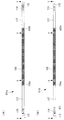
図1から図5を参照して本実施形態に係るセルスタックについて説明する。図1は、本実施形態に係るセルスタックの側面図である。同図において(A)はAタイプセルスタックの側面図、(B)はBタイプセルスタックの側面図である。図2は、図1(A)の正極側の矢印X−Xの矢視断面図である。図3は、図2(A)の負極側の矢印Y−Yの矢視断面図である。図4は、図2(B)の負極側の矢印X−Xの矢視断面図である。図5は、図2(B)の正極側の矢印Y−Yの矢視断面図である。
[First Embodiment]
The cell stack according to the present embodiment will be described with reference to FIGS. FIG. 1 is a side view of a cell stack according to the present embodiment. In the same figure, (A) is a side view of an A type cell stack, and (B) is a side view of a B type cell stack. FIG. 2 is a cross-sectional view taken along arrow XX on the positive electrode side in FIG. FIG. 3 is a cross-sectional view taken along arrow YY on the negative electrode side in FIG. FIG. 4 is a cross-sectional view taken along arrow XX on the negative electrode side of FIG. FIG. 5 is a cross-sectional view taken along arrow YY on the positive electrode side in FIG.
複数のセルスタックには、Aタイプセルスタック(第1セルスタック)101aと、Bタイプセルスタック(第2セルスタック)101bとがある。はじめに、各セルスタックに共通する点について説明する。
セルスタック(101a,101b)は、円筒形状の基体管103と、基体管103の外周面上に複数形成された燃料電池セル105と、隣り合う燃料電池セル105の間に形成されたインターコネクタ107とを有する。燃料電池セル105は、燃料極109と固体電解質111と空気極113とが積層して形成されている。
The plurality of cell stacks include an A type cell stack (first cell stack) 101a and a B type cell stack (second cell stack) 101b. First, points common to each cell stack will be described.
The cell stack (101a, 101b) includes a
セルスタック(101a,101b)は、基体管103の外周面上に形成された複数の燃料電池セル105の内、基体管103の軸方向において最も端に形成された燃料電池セル105に電気的に接続されたリード部114(114a,114b)を有する。リード部114(114a,114b)は、電気的に接続された複数の燃料電池セル105の両端部にある。基体管103の一端部側にあるリード部114aの長さは、他端部側にあるリード部114bよりも長い。リード部114(114a,114b)は、燃料電池セル105に電気的に接続されたリード膜115(115a,115b)と、リード膜115上に形成された保護膜117とを含んでいる。リード膜115は、基体管上に形成されており、一端が燃料電池セル105に電気的に接続され、他端は基体管103の端部に向けて延びている。リード膜115は、基体管103の端部側で上面が露出されている。リード膜115を覆う保護膜117の上には、適宜シール接合膜119が積層されていてもよい。リード膜115は、リード部114aのリード膜115aの長さ(La)が、リード部114bのリード膜115bの長さ(Lb)よりも長い。
The cell stack (101a, 101b) is electrically connected to the
基体管103は、多孔質材料からなり、例えば、CaO安定化ZrO2(CSZ)、又はY2O3安定化ZrO2(YSZ)、又はMgAl2O4とされる。この基体管103は、燃料電池セル105とインターコネクタ107とリード膜115とを支持すると共に、基体管103の内周面に供給される燃料ガスを基体管103の細孔を介して基体管103の外周面に形成される燃料極109に拡散させるものである。
The
基体管103は円筒型の長尺部材である。基体管103は軸方向(長手方向)に向けて気孔率分布を有している。基体管103の気孔率は、基体管103の一端部側に対して他端部側が大きくなる。
The
燃料極109は、Niとジルコニア系電解質材料との複合材の酸化物で構成され、例えば、Ni/YSZが用いられる。この場合、燃料極109は、燃料極109の成分であるNiが燃料ガスに対して触媒作用を有する。この触媒作用は、基体管103を介して供給された燃料ガス、例えば、メタン(CH4)と水蒸気との混合ガスを反応させ、水素(H2)と一酸化炭素(CO)に改質するものである。また、燃料極109は、改質により得られる水素(H2)及び一酸化炭素(CO)と、固体電解質111を介して供給される酸素イオン(O2−)とを固体電解質111との界面付近において電気化学的に反応させて水(H2O)及び二酸化炭素(CO2)を生成するものである。なお、燃料電池セル105は、この時、酸素イオンから放出される電子によって発電する。また、燃料極109は所定膜厚を得るために複数に分けて形成しても良い。
The
固体電解質111は、ガスを通しにくい気密性と、高温で高い酸素イオン導電性とを有するYSZが主として用いられる。この固体電解質111は、空気極で生成される酸素イオン(O2−)を燃料極に移動させるものである。また、固体電解質111は所定機能を得るために複数に分けて形成しても良い。
The
空気極113は、例えば、LaSrMnO3系酸化物、又はLaCoO3系酸化物で構成される。この空気極113は、固体電解質111との界面付近において、供給される空気等の酸化性ガス中の酸素を解離させて酸素イオン(O2−)を生成するものである。
The
インターコネクタ107は、SrTiO3系などのM1−xLxTiO3(Mはアルカリ土類金属元素、Lはランタノイド元素)で表される導電性ペロブスカイト型酸化物から構成され、燃料ガスと酸化性ガスとが混合しないように緻密な膜となっている。また、インターコネクタ107は、酸化雰囲気と還元雰囲気との両雰囲気下で安定した電気導電性を有する。このインターコネクタ107は、隣り合う燃料電池セル105において、一方の燃料電池セル105の空気極113と他方の燃料電池セル105の燃料極109とを電気的に接続し、隣り合う燃料電池セル105同士を直列に接続するものである。また、インターコネクタ107は所定機能を得るために複数に分けて形成しても良い。
The
リード膜115は、電子伝導性を有すること、及びセルスタック(101a,101b)を構成する他の材料との熱膨張係数が近いことが必要であることから、Ni/YSZ等のNiとジルコニア系電解質材料との複合材で構成されている。リード膜の材料は燃料極の材料を同じであってよい。このリード膜115は、インターコネクタにより直列に接続される複数の燃料電池セル105で発電された直流電力をセルスタック(101a,101b)の端部付近まで導出すものである。
Since the
保護膜117は、固体電解質111と同じ材料で構成されている。保護膜117は、燃料ガスおよび酸化性ガスのリークを防止する役割と、リード膜115が酸化性ガスに曝されるのを防ぐ役割を果たす。
The
シール接合膜119は、セルスタック101と接着剤との接着強度を向上させるために表面粗度を高くするという役割を果たす膜である。シール接合膜119の材料は例えばCaTiO3とYSZの混合物である。シール接合膜119は、ローラー印刷で形成されるとよい。
The
次に、各セルスタックの特徴について説明する。
Aタイプセルスタック101aは、正極側に比べ負極側の基体管103の気孔率が大きいセルスタックである。Aタイプセルスタック101aにおいて、正極側に設けられたリード部114aおよびリード膜115aの長さ(La)が、負極側に設けられたリード部114bおよびリード膜115bの長さ(Lb)よりも長い。Aタイプセルスタック101aにおいて、負極側にある燃料電池セル105bは正極側にある燃料電池セル105aよりも長い。
Next, features of each cell stack will be described.
The
Bタイプセルスタック101bは、負極側に比べ正極側の基体管103の気孔率が大きいセルスタックである。Bタイプセルスタック101bにおいて、負極側に設けられたリード部114aおよびリード膜115aの長さ(La)が、正極側に設けられたリード部114bおよびリード膜115bの長さ(Lb)よりも長い。Bタイプセルスタック101bにおいて、正極側にある燃料電池セル105bは負極側にある燃料電池セル105aよりも長い。
The B
Aタイプセルスタック101aおよびBタイプセルスタック101bの少なくとも一方のセルスタックには、リード部上に識別部121が設けられているとよい。識別部121は、リード部上の形成される箇所に応じて各層の形成膜と同一の材料を用いて設置する。例えば、図4では識別部121を保護膜117上に形成しているが、この場合、識別部121の材料はシール接合膜119と同一の材料を用い、シール接合膜119を印刷するタイミングに合わせて成膜するとよい。例えば115a上に、保護膜117の端部と間隔をあけて形成する場合、識別部121は、保護膜117と同一な材料を用いて、保護膜117の形成に併せて容易に設置することができる(不図示)。
In at least one of the A
識別部121はAタイプセルスタック101aとBタイプセルスタック101bとを外観で識別できるよう形成されたものである。例えば、Bタイプセルスタック101bの負極側のリード部114a上に環状ラインの識別部121が設けられるとよい。なお、Aタイプセルスタック101aおよびBタイプセルスタック101bの両方に識別部121を設ける場合には、識別部121の位置、形状などをパターン分けする。
The
識別部121は上記の環状ラインに限定されるものでなく、製造工程の中で併せて設けることができ、外観識別ができれば形状を適宜変更が可能である。
The
Aタイプセルスタック101aおよびBタイプセルスタック101bは以下のように製造することができる。図6に、吊り下げ焼成する際のAタイプセルスタック101aおよびBタイプセルスタック101bの概略側面図を示す。同図において(A)は吊り下げ焼成する際のAタイプセルスタック、(B)は吊り下げ焼成する際のBタイプセルスタック、紙面上側が鉛直方向上である。簡略化のため図6では、未焼成の燃料電池セル105’、未焼成のリード部114a’,114b’、および未焼成の識別部121’を表示している。
The A
まず、カルシウム安定化ジルコニア(CSZ)などの材料を、押し出し成形法により円筒形である基体管103の形状に成形する(以降「成形した基体管」と呼ぶ)。次に、燃料極材料、固体電解質材料、インターコネクタ材料、リード膜材料、および保護膜材料それぞれ水系ビヒクルなどを混合し、スラリーを作製する。スクリーン印刷法を用いて、燃料極用スラリー、リード膜用スラリー、固体電解質用スラリー、保護膜用スラリー、およびインターコネクタ用スラリーを成形した基体管上に順に成膜する。
First, a material such as calcium-stabilized zirconia (CSZ) is formed into a
本実施形態では、燃料極109およびリード膜115、固体電解質111および保護膜117を同じ材料で構成する。よって、燃料極用スラリーおよびリード膜用スラリーを作製・印刷する工程は実質的に同じ工程である。また、固体電解質用スラリーおよび保護膜用スラリーを作製・印刷する工程も実質的に同じ工程である。リード膜用スラリーは、Aタイプセルスタック101aの正極側およびBタイプセルスタック101bの負極側の方のリード膜115aが、Aタイプセルスタック101aの負極側およびBタイプセルスタック101bの正極側の方のリード膜115bよりも長くなるように印刷する。保護膜用スラリーは、リード膜115の上面が基体管103の端部で露出するよう、リード膜用スラリーの上に印刷する。
In the present embodiment, the
他端部側(リード膜が短い方)が鉛直方向上に向くよう成形した基体管を吊り下げる。Aタイプセルスタック101aは負極側、Bタイプセルスタック101bは正極側が鉛直方向上に向ける。Aタイプセルスタック101aは正極側、Bタイプセルスタック101bは負極側が鉛直方向下に向ける。大気中にて1350℃〜1500℃、3時間〜5時間、一体焼成して、基体管103、燃料極109、リード膜115、固体電解質111、インターコネクタ107、および保護膜117を形成する。
The base tube formed so that the other end side (the one with the shorter lead film) faces in the vertical direction is suspended. The A
次に、空気極材料に水系ビヒクルを混合して空気極用スラリーを作製する。焼成後のインターコネクタ107上に空気極用スラリーをスクリーン印刷する。また、シール接合膜材料に水系ビヒクルを混合してシール接合膜用スラリーを作製する。焼結後の保護膜117の上にシール接合膜用スラリーをローラー印刷する。識別部121を形成するための識別部用スラリーには、シール接合膜用スラリーを転用する。識別部用スラリーは、成膜したシール接合膜用スラリーの端部と間隔をあけるよう成膜した保護膜用スラリー上にスクリーン印刷する。その後、他端部側(リード膜が短い方)が鉛直方向上に向くよう基体管103を吊り下げ、大気中にて1100℃〜1400℃、1時間〜4時間で焼成し、空気極113を形成する。
Next, a water-based vehicle is mixed with the air electrode material to prepare an air electrode slurry. A slurry for the air electrode is screen-printed on the
上記のように製造したAタイプセルスタック101aおよびBタイプセルスタック101bは、極性のみが反転したセルスタックとなる。吊り下げ焼成すると、鉛直方向下側(下側)では基体管が収縮されるが、鉛直方向上側(上側)では自重により基体管が下側ほど収縮しない。そのため、焼成後の基体管では上側にあった方の気孔率が大きくなり、下側にあった方の気孔率が小さくなる。
The A
また成形した基体管、燃料極材料、固体電解質材料などを吊り下げて一体焼成すると基体管の軸方向に自重がかかり、各素子(燃料極109、固体電解質111、インターコネクタ107などによる燃料電池セル)は基体管の軸方向で長さに違いが生じる。吊り下げた際に鉛直方向上側に配置された各素子は、鉛直方向下側に配置された各素子よりも長くなる。たとえば、鉛直方向上側に配置された素子は、鉛直方向下側に配置された素子に比べて素子長さが約8%長くなる。
In addition, when the molded base tube, fuel electrode material, solid electrolyte material, etc. are suspended and integrally fired, the weight of the base tube is self-weighted, and a fuel battery cell by each element (
識別部用スラリーは、成形した基体管を焼成する前に成膜されているため、一体焼成の際にセルスタックの吊り下げる向きを間違えにくくなる。リード部114aおよびリード部114bの長さで吊り下げる向きを確認できるとともに、識別部121を設けることで、Aタイプセルスタック101aおよびBタイプセルスタック101bを外観で識別できる。
Since the identification portion slurry is formed before firing the formed base tube, it is difficult to mistake the direction in which the cell stack is suspended during the integral firing. The direction of hanging by the length of the
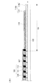
次に、本実施形態に係る燃料電池(SOFC)カートリッジについて説明する。図7は、本実施形態に係るSOFCカートリッジの概略構成図である。SOFCカートリッジ203は、ケーシング229と、複数のセルスタック(Aタイプセルスタック101aおよびBタイプセルスタック101b)と、発電室215と、燃料ガス供給室217と燃料ガス排出室219とを有する。また、SOFCカートリッジは、上部管板225aと下部管板225bとを有する。
Next, the fuel cell (SOFC) cartridge according to the present embodiment will be described. FIG. 7 is a schematic configuration diagram of the SOFC cartridge according to the present embodiment. The
発電室215は、ケーシング229と上部管板225aと下部管板225bとの間に形成された領域である。セルスタック(101a,101b)の燃料電池セル105が配置され、燃料ガスと酸化性ガスとを電気化学的に反応させて発電を行う領域である。また、この発電室215のセルスタック101長手方向の中央部付近での温度は、燃料電池モジュールの定常運転時に、およそ700℃〜1000℃の高温雰囲気となる。酸化性ガスは発電室215のセルスタック(101a,101b)の外側に供給され、セルスタック(101a,101b)の長手方向と直交する方向へ流れる。本説明では、酸化性ガスがセルスタック(101a,101b)の長手方向と直交する方向へ流れるとして説明するが、酸化性ガスは後述するように燃料ガスの流れと対向してセルスタック(101a,101b)の長手方向に流れるよう供給してもよい。
The
燃料ガス供給室217は、ケーシング229の上部と上部管板225aとで囲まれた領域である。燃料ガス供給室217は、ケーシング229の上部に備えられた燃料ガス供給孔231aによって、図示しない燃料ガス供給枝管と連通されている。また、燃料ガス供給室217には、円筒形状であるセルスタック(101a,101b)の一方の端部が燃料ガス供給室217に対して開放して配置されている。セルスタック101の一方の端部とは、基体管の気孔率が小さい方(吊り下げ焼成時に鉛直方向下を向いていた方)の端部であり、全てのセルスタック101について同様な方向で気孔率の小さい方が配置される。燃料ガス供給室217は、図示しない燃料ガス供給枝管から燃料ガス供給孔231aを介して供給される燃料ガスを、複数のセルスタック101の基体管103の内部に略均一流量で導き、複数のセルスタック101の発電性能を略均一化させるものである。
The fuel
燃料ガス排出室219は、ケーシング229の下部と下部管板225bとで囲まれた領域である。燃料ガス排出室219は、ケーシング229の下部に備えられた燃料ガス排出孔231bによって、図示しない燃料ガス排出枝管と連通されている。また、燃料ガス排出室219には、円筒形状であるセルスタック(101a,101b)の他方の端部が、燃料ガス排出室219に対して開放して配置されている。セルスタック(101a,101b)の他方の端部とは、燃料ガス供給室217に対して開放している端部とは異なる、基体管の気孔率が大きくなる方(吊り下げ焼成時に鉛直方向上を向いていた方)の端部であり、全てのセルスタック101について同様な方向で気孔率の大きい方が配置される。燃料ガス排出室219は、複数のセルスタック(101a,101b)の基体管103の内部を通過して燃料ガス排出室219に供給される排燃料ガスを集約して、燃料ガス排出孔231bを介して図示しない燃料ガス排出枝管に導くものである。
The fuel
上部管板225aは、ケーシング229の上部の側板に固定されている。上部管板225aはSOFCカートリッジ203に備えられるセルスタック(101a,101b)の本数に対応した複数の孔を有し、該孔にはセルスタック(101a,101b)が夫々挿入されている。この上部管板225aは、複数のセルスタック(101a,101b)の一方の端部(上端部)をシール部材及び接着部材のいずれか一方又は両方を介して気密に支持している。下部管板225bは、ケーシング下部の側板に固定されている。下部管板225bはSOFCカートリッジ203に備えられるセルスタック(101a,101b)の本数に対応した複数の孔を有し、該孔にはセルスタック(101a,101b)が夫々挿入されている。この下部管板225bは、複数のセルスタック(101a,101b)の他方の端部(下端部)をシール部材及び接着部材のいずれか一方又は両方を介して気密に支持している。
The
セルスタック(101a,101b)には、上部管板225aおよび下部管板225bとのシール部分にはシール接合膜119を設けて表面粗度を高くしてあり、セルスタック(101a,101b)とシール部材及び接着部材との接着強度を向上させてある。
The cell stack (101a, 101b) is provided with a
複数のセルスタックは、複数のAタイプセルスタック101aおよび複数のBタイプセルスタック101bを含む。
複数のAタイプセルスタック101aは集電部材(上部集電部材211aまたは下部集電部材212a)により電気的に並列接続されてAタイプセルスタック群214aを構成する。Aタイプセルスタック群214aにおいて、複数のAタイプセルスタック101aは、正極を燃料ガス供給室側(鉛直方向上側)に向け、負極を燃料ガス排出室側(鉛直方向下側)に向けて横に並べて配置されている。複数のAタイプセルスタック101aの正極側端部は、上部集電部材211aで集合化されている。複数のAタイプセルスタック101aの負極側端部は、下部集電部材211bによって集合化されている。上部集電部材211aおよび下部集電部材211bはそれぞれ導電性を有する。
The plurality of cell stacks include a plurality of A
The plurality of A
複数のBタイプセルスタック101bは集電部材(上部集電部材211bまたは下部集電部材212b)により電気的に並列接続されてBタイプセルスタック群214bを構成する。Bタイプセルスタック群214bにおいて、複数のBタイプセルスタックは、負極を燃料ガス供給室側(鉛直方向上側)に向け、正極を燃料ガス排出室側(鉛直方向下側)に向けて横に並べて配置されている。複数のBタイプセルスタック101bの負極側端部は、上部集電部材211aで集合化されている。複数のBタイプセルスタック101bの正極側端部は、下部集電部材211bによって集合化されている。
The plurality of B
Aタイプセルスタック群214aおよびBタイプセルスタック群214bは、1つのSOFCカートリッジ内で交互に並べて配置されている。隣り合うAタイプセルスタック群214aおよびBタイプセルスタック群214bは、隣り合う集電部材(例えば211aと211b)が適宜つながれて電気的に直列接続されている。最端部のセルスタック群を集合化する集電部材(211a,211b)には集電棒216がつながれている。
The A type
隣のセルスタック群と電気的に接続されていない集電部材(上部集電部材211a,211bまたは下部集電部材212a,212b)は、相互集電部材間の異常放電を抑制するために、隣にある集電部材とセルスタックの軸方向において位置がずれていることが好ましい。例えば図8に示すように、Aタイプセルスタック群214aにおける集電部材を、Bタイプセルスタック群214bにおける集電部材よりもセルスタックの端部側(燃料ガスの流れ方向上流側)に所定距離以上ずらすとよい。「所定距離」は隣り合う集電部材の端部同士が接触しない距離であり、相互集電部材間の異常放電を抑制できる距離である。図8では、Aタイプセルスタック群214aにおける集電部材221aと、Bタイプセルスタック群214bにおける集電部材221bとは、軸方向に3mm以上、例えば6mm程度ずらす。
The current collecting members (upper
また、相互集電部材間の異常放電をさらに抑制するために、異常放電の起点となり易い板部材の端部間の距離が離れるように、隣のセルスタック群と電気的に接続されていない集電部材(上部集電部材211a,211bまたは下部集電部材212a,212b)の端部は、それぞれ隣りの集電部材から離れる方向に向けて曲がっているとよい。例えば図8に示すように、Aタイプセルスタック群214aにおける集電部材の端部が紙面上側に曲がっており、Bタイプセルスタック群214bにおける集電部材の端部が紙面下側(Aタイプセルスタック群214aにおける集電部材の端部とは逆の方向)に曲がっているとよい。
Further, in order to further suppress abnormal discharge between the mutual current collecting members, a current collector that is not electrically connected to the adjacent cell stack group is separated so that the distance between the end portions of the plate member that is likely to be the starting point of abnormal discharge is increased. The end portions of the electric members (upper
本実施形態によれば、SOFCカートリッジ内に極性を反転させたAタイプセルスタック101aおよびBタイプセルスタック101bを配置することで、SOFCカートリッジ内の配線をセルスタックの一方の端部側および他方の端部側において、一方向にまとめられる。それにより集電をセルスタックの一方の端部側から他方の端部側へと接続するための配線部材の取り回しが不要となり、Aタイプセルスタック101aとBタイプセルスタック101bとの接続配線部材を短くでき、直列配線が容易となる。
According to the present embodiment, by arranging the A
従来のようにセルスタック間の直列接続にあたり、同一極性のセルスタックを上下で反転させて並べる前述のような効率的な直列配線を得ることが出来るが、基体管の軸方向の気孔率分布も上下で反転してしまうことで、上下反転したセルスタックの発電電流が異なるために、そのまま直列接続するとセルスタック全体の発電性能が低下する課題がある。本実施形態では、Aタイプセルスタック101aとBタイプセルスタック101aとは極性を反転させて並べた場合に、基体管の軸方向の気孔率分布は全てのセルスタックで同じ傾向を示すよう製造している。本実施形態によれば、気孔率の大きい方を同じ向きに配置して燃料ガス排出側に配置することができるため、セルスタックの電流を律速していた燃料ガスの流れ方向下流側での発電反応量を増加させ、セルスタック全体の発電能力を上げることができる。
In series connection between cell stacks as in the past, it is possible to obtain efficient series wiring as described above in which cell stacks of the same polarity are inverted and arranged, but the porosity distribution in the axial direction of the base tube is also Since the generated currents of the inverted cell stacks are different by being inverted up and down, there is a problem in that the power generation performance of the entire cell stack is reduced if they are connected in series as they are. In this embodiment, when the A
またセルスタック(Aタイプセルスタック101aおよびBタイプセルスタック101b)において、基体管の気孔率が大きくなる方(吊り下げ焼成時に鉛直方向上側を向いていた方)では、基体管の気孔率が小さくなる方よりも各素子(燃料電池セル)の長さが長くなっている。セルスタックの上側と下側において流れる電流は同じである。燃料電池セルが長いと電流の流れる面積が広くなり、単位面積当たりの電流が低くなる(電流密度が低下する)。そのため、長い燃料電池セルでは、短い燃料電池セルよりも実質的に電圧が高くなり、結果として燃料電池の性能が向上する。
Further, in the cell stack (A
SOFCカートリッジ203において、基体管の気孔率が小さい側は、燃料ガスの流れ方向上流側であり、長いリード部114aが必要な領域に配置されている。リード部では、発電がおこなわれないため基体管の気孔率が小さいことによる発電効率への影響は少ない。
In the
次に、本実施形態に係る燃料電池(SOFC)モジュールおよび燃料電池について説明する。図9は、本実施形態に係る燃料電池の概略構成図である。燃料電池1は、SOFCモジュールと、各SOFCカートリッジに対応付けられるチョッパ218と、インバータ220と、制御部(不図示)とを備えている。
Next, a fuel cell (SOFC) module and a fuel cell according to this embodiment will be described. FIG. 9 is a schematic configuration diagram of the fuel cell according to the present embodiment. The
SOFCモジュール201は、複数のSOFCカートリッジ203と、複数のSOFCカートリッジを収納する圧力容器(不図示)とを有する。また、SOFCモジュール201は、燃料ガス供給管(不図示)と複数の燃料ガス供給枝管(不図示)とを有する。またSOFCモジュール201は、燃料ガス排出管(不図示)と複数の燃料ガス排出枝管(不図示)とを有する。また、SOFCモジュール201は、酸化性ガス供給管(不図示)と酸化性ガス供給枝管(不図示)とを有する。また、SOFCモジュール201は、酸化性ガス排出管(不図示)と複数の酸化性ガス排出枝管(不図示)とを有する。
The
燃料ガス供給管は、SOFCモジュール201の発電量に対応して所定ガス組成と所定流量の燃料ガスを供給する燃料ガス供給部に接続されると共に、複数の燃料ガス供給枝管に接続されている。この燃料ガス供給管は、上述の燃料ガス供給部から供給される所定流量の燃料ガスを、複数の燃料ガス供給枝管に分岐して複数のSOFCカートリッジへと導くものである。また、燃料ガス供給枝管は、燃料ガス供給管に接続されると共に、複数のSOFCカートリッジ203に接続されている。この燃料ガス供給枝管は、燃料ガス供給管から供給される燃料ガスを複数のSOFCカートリッジ203に略均等の流量で導き、複数のSOFCカートリッジ203の発電性能を略均一化させるものである。
The fuel gas supply pipe is connected to a fuel gas supply section that supplies a predetermined gas composition and a predetermined flow rate of fuel gas corresponding to the power generation amount of the
燃料ガス排出枝管は、複数のSOFCカートリッジ203に接続されると共に、燃料ガス排出管に接続されている。この燃料ガス排出枝管は、SOFCカートリッジ203から排出される排燃料ガスを燃料ガス排出管に導くものである。また、燃料ガス排出管は、複数の燃料ガス排出枝管に接続されると共に、一部が圧力容器の外部に配置されている。この燃料ガス排出管は、燃料ガス排出枝管から略均等の流量で導出される排燃料ガスを圧力容器の外部に導くものである。
The fuel gas discharge branch pipe is connected to the plurality of
圧力容器は、内部の圧力が0.1MPa〜約1MPa、内部の温度が大気温度〜約550℃で運用されるので、耐力性と酸化性ガス中に含まれる酸素などの酸化剤に対する耐食性を保有する材質が利用される。例えばSUS304などのステンレス系材が好適である。 The pressure vessel is operated at an internal pressure of 0.1 MPa to about 1 MPa and an internal temperature of atmospheric temperature to about 550 ° C., so it possesses proof stress and corrosion resistance against oxidizing agents such as oxygen contained in the oxidizing gas. The material to be used is used. For example, a stainless steel material such as SUS304 is suitable.
ここで、本実施形態においては、複数のSOFCカートリッジ203が集合化されて圧力容器205に収納される態様について説明しているが、これに限られず例えば、SOFCカートリッジ203が集合化されずに圧力容器205内に収納される態様とすることもできる。
Here, in the present embodiment, a mode has been described in which a plurality of
チョッパ218は、各SOFCカートリッジ203に対応付けて設けられている。チョッパ218は、SOFCカートリッジ203の第1出力レベルを、第1出力レベルとは異なる第2出力レベルの発電出力に変換させる。各チョッパ218は制御部からの指示によって、各SOFCカートリッジ203からインバータ220へ流入する電流の大きさを制御できる。インバータ220は、チョッパ218で変換された出力を所定の交流電力へと変換する。図9では、複数のチョッパ218に対して1つのインバータ220が接続されているが、インバータ220はチョッパ218に対応付けてそれぞれ設けられてもよい。
The
上記実施形態では、発電室215で発電された直流電力は、複数の燃料電池セル105に設けたNi/YSZ等からなるリード膜115によりセルスタック101の端部付近まで導出した後に、保護膜117に覆われなく、リード膜115の上面が露出している基体管103の端部で集電部材(211、212)と電気的に接続される。SOFCカートリッジ203の集電棒216に集電部材(211、212)を介して集電して、各SOFCカートリッジ203の外部へと取り出される。前記集電棒216によってSOFCカートリッジ203の外部に導出された電力は、各SOFCカートリッジ203の発電電力を所定の直列数および並列数へと相互に接続され、SOFCモジュール201の外部へと導出されて、インバータにより所定の交流電力へと変換されて、電力負荷へと供給される。
In the above embodiment, the direct current power generated in the
本実施形態によれば、従来、SOFCカートリッジ203の上部及び下部に配置していた正極と負極のターミナル(集電棒216)について、SOFCカートリッジ203に備えるセルスタック群を偶数個とすることで、SOFCカートリッジ203から最終的に出る正極と負極とのターミナルが、例えばSOFCカートリッジ203の上側に共通化して配置可能となるため、SOFCモジュール内でのSOFCカートリッジ203間の結線が容易になる。
According to the present embodiment, the
〔第2実施形態〕
本実施形態は、SOFCカートリッジの構成および集電方法が第1実施形態と異なる。特に説明のない構成については、第1実施形態と同様である。図10は、本実施形態に係る燃料電池の概略構成図である。図11は、SOFCカートリッジの概略縦断面図である。同図において、(A)はAタイプカートリッジ、(B)はBタイプカートリッジである。図12は、SOFCモジュールの概略斜視図である。
[Second Embodiment]
This embodiment is different from the first embodiment in the configuration of the SOFC cartridge and the current collecting method. Unless otherwise specified, the configuration is the same as that of the first embodiment. FIG. 10 is a schematic configuration diagram of the fuel cell according to the present embodiment. FIG. 11 is a schematic longitudinal sectional view of the SOFC cartridge. In the figure, (A) is an A type cartridge and (B) is a B type cartridge. FIG. 12 is a schematic perspective view of the SOFC module.
燃料電池10は、複数のSOFCカートリッジ(303a,303b)を備えているSOFCモジュール301と、各SOFCカートリッジ(303a,303b)に対応付けられるチョッパ318と、インバータ319と、制御部(不図示)とを備えている。
The
まず、SOFCカートリッジの構成について説明する。
複数のSOFCカートリッジは、タイプの異なる2種類のカートリッジ(Aタイプカートリッジ303aおよびBタイプカートリッジ303b)を含む。SOFCカートリッジは、集電部材で複数のセルスタックを電気的に並列接続したセルスタック群を複数有している。1つのSOFCカートリッジは、1種類のセルスタック群のみを含む。1つのSOFCカートリッジに含まれる複数のセルスタック群は、極性の向きが揃っている。各SOFCカートリッジに含まれるセルスタック群の数は、SOFCカートリッジの種類によらず同じである。
First, the configuration of the SOFC cartridge will be described.
The plurality of SOFC cartridges include two types of cartridges (A
Aタイプカートリッジ303aに含まれるセルスタック群は、Aタイプセルスタック群314aのみである。Aタイプセルスタック群314aは、複数のAタイプセルスタック101aを集電部材(311a,312a)で電気的に並列接続したセルスタック群である。Aタイプセルスタック101aは、第1実施形態と同様に正極側に比べ負極側の基体管の気孔率が大きくなるセルスタックである。Aタイプセルスタック101aでは、正極側のリード部が負極側のリード部よりも長い。Aタイプセルスタック101aでは、正極側の燃料電池セルよりも負極側の燃料電池セルの方が長い。
The cell stack group included in the
Aタイプカートリッジ303aでは、Aタイプセルスタック101aの正極が燃料ガスの流れ方向上流側に向き、負極が燃料ガスの流れ方向下流側に向くようAタイプセルスタック群314aが配置されている。Aタイプカートリッジ303aでは、複数のAタイプセルスタック群の極性の向きは一方に揃っている。Aタイプカートリッジ内にある複数のAタイプセルスタック群314aは、それぞれ電気的に分離されている。
In the A
Bタイプカートリッジ303bに含まれるセルスタック群は、Bタイプセルスタック群314bのみである。Bタイプセルスタック群314bは、複数のBタイプセルスタック101bを集電部材(311b,312b)で電気的に並列接続したセルスタック群である。Bタイプセルスタック101bは、第1実施形態と同様に負極側に比べ正極側の基体管の気孔率が大きくなるセルスタックである。Bタイプセルスタック101bでは、負極側のリード部が正極側のリード部よりも長い。Bタイプセルスタック101bでは、負極側の燃料電池セルよりも正極側の燃料電池セルの方が長い。
The cell stack group included in the
Bタイプカートリッジ303bでは、Bタイプセルスタック101bの負極が燃料ガスの流れ方向上流側に向き、正極が燃料ガスの流れ方向下流側に向くようBタイプセルスタック群314bが配置されている。Bタイプカートリッジ303bでは、複数のBタイプセルスタック群314bの極性の向きは一方に揃っている。Bタイプカートリッジ303bの一方の極性は、Aタイプカートリッジ303aの一方の極性とは異なる。Bタイプカートリッジ内にある複数のBタイプセルスタック群314bは、それぞれ電気的に分離されている。
In the
次に、SOFCモジュール301について説明する。SOFCモジュール301は、複数のSOFCカートリッジを有する。複数のSOFCカートリッジはAタイプカートリッジ303aとBタイプカートリッジ303bとから構成されている。
Next, the
Aタイプカートリッジ303aおよびBタイプカートリッジ303bは、SOFCカートリッジ内のAタイプ,Bタイプの同一タイプのセルスタック群を並べたもので、Aタイプカートリッジ303aおよびBタイプカートリッジ303bは、SOFCモジュール内に交互に配置されている。図10では電気的接続関係が判り易いように、一列に並べた模式図とすることで説明しているが、設置形態や配置形態そのものを限定している訳ではない。例えば、Aタイプカーリッジ内で並んで集合させたAタイプセルスタック群314aと、該Aタイプカートリッジ303aの隣に配置されたBタイプカートリッジ内で並んで集合させたBタイプセルスタック群314bとは、隣接して並んでいる。
The
各SOFCカートリッジ内でそれぞれ対応する位置に配置されたAタイプセルスタック群314aとBタイプセルスタック群314bとはSOFCカートリッジ(303a,303b)を区分けしている枠を超えて集電部材(316a,316b,313)により電気的に直列接続されている。図10では隣り合うAタイプセルスタック群314aとBタイプセルスタック群314bとが直列接続されて、集電群(320,321,322,323)を構成している。集電群(320,321,322,323)は、SOFCカートリッジ内で列の端部側のセルスタック群同士、および列の中央部分のセルスタック群同士で構成されるとよい。
The A-type
チョッパ318は、各集電群(320,321,322,323)に対応付けて設けられている。チョッパ318は、各集電群(320,321,322,323)の第1出力レベルを、第1出力レベルとは異なる第2出力レベルの発電出力に変換させる。各チョッパは図示しない制御部からの指示によって、各集電群(320,321,322,323)からインバータ319へ流入する電流の大きさを制御できる。インバータ319は、チョッパ318で変換された出力を所定の交流電力へと変換する。図10では、複数のチョッパ318に対して1つのインバータ319が接続されているが、インバータ319はチョッパ318に対応付けてそれぞれ設けられてもよい。
The
燃料電池10は、カートリッジ内の各セルスタック群の温度を計測できる温度計測部11を備えていることが好ましい。温度計測部11は、カートリッジ内の空気温度を計測できるものである。温度計測部11で計測された温度は、図示しない制御部へと出力される。制御部は、該出力された温度に基づいて、各セルスタック群の温度が均一になるようチョッパ318へと指示を出す。チョッパ318は、相対的に温度が低いセルスタック群を含む集電群に、相対的に温度が高いセルスタック群を含む集電群よりも大きな電流が流れるように調整する。
The
本実施形態によれば、各カートリッジで列の端部側にあるセルスタック群同士をつなげた集電群(320,323)と、中央部分にあるセルスタック群同士をつなげた集電群(321,322)とでそれぞれに電流を制御することが可能となる。それによって、端部側・中央部分の温度差が小さくなるように制御できる。 According to the present embodiment, the current collection group (320, 323) in which the cell stack groups on the end side of the column are connected to each other in each cartridge and the current collection group (321 in which the cell stack groups in the central portion are connected to each other) , 322) and current can be controlled respectively. Thereby, it can control so that the temperature difference of an edge part side and a center part becomes small.
従来のようにセルスタック間の直列接続にあたり、同一極性のセルスタックを上下で反転させて並べると、前述のような効率的な直列配線を得ることが出来るが、基体管103の軸方向の気孔率分布も反転してしまうために、上下反転したセルスタックの発電電流が異なるために、そのまま直列接続するとセルスタック全体の発電性能が低下する。本実施形態では、AタイプセルスタックとBタイプセルスタックとは極性を反転させて並べた場合に、基体管の軸方向の気孔率分布は同じ傾向を示すよう製造している。本実施形態によれば、気孔率の大きい方を同じ向きに配置して燃料ガス排出側に配置することができるため、セルスタックの電流を律速していた燃料ガスの流れ方向下流側での発電反応量を増加させ、セルスタック全体の発電能力を上げることができる。
In the conventional series connection between the cell stacks, if the cell stacks of the same polarity are reversed and arranged side by side, an efficient series wiring as described above can be obtained, but the axial pores of the
またセルスタック(AタイプセルスタックおよびBタイプセルスタック)において、基体管103の気孔率が大きくなる方(吊り下げ焼成時に鉛直方向上側を向いていた方)では、基体管103の気孔率が小さくなる方よりも各素子(燃料電池セル)の長さが長くなっている。セルスタックの上側と下側において流れる電流は同じである。燃料電池セル105が長いと電流の流れる面積が広くなり、単位面積当たりの電流が低くなる(電流密度が低下する)。そのため、長い燃料電池セル105では、短い燃料電池セル105よりも実質的に電圧が高くなり、結果として燃料電池の性能が向上する。
Further, in the cell stack (A type cell stack and B type cell stack), the porosity of the
SOFCカートリッジにおいて、基体管103の気孔率が小さい側は、燃料ガスの流れ方向上流側であり、長いリード膜が必要な領域に配置されている。そのため、発電効率への影響は少ない。
In the SOFC cartridge, the low porosity side of the
本実施形態では、1つのカートリッジ内には種類の異なるカートリッジが混在していない。カートリッジ内で各セルスタック群は同じ並列電流で並んでいるため、各セルスタック群間で過電圧が印加されない。よって、クリープ変形等でセルスタック群同士が接触した場合においても各セルスタック群間での電圧差は小さいので、燃料電池セル105が損傷するリスクを低減できる。
In this embodiment, different types of cartridges are not mixed in one cartridge. Since the cell stack groups are arranged with the same parallel current in the cartridge, no overvoltage is applied between the cell stack groups. Therefore, even when the cell stack groups contact each other due to creep deformation or the like, the voltage difference between the cell stack groups is small, so that the risk of damage to the
なお、本発明は上述した実施形態に限定されることなく、その要旨を逸脱しない範囲において適宜変更することができる。 In addition, this invention is not limited to embodiment mentioned above, In the range which does not deviate from the summary, it can change suitably.
1,10 燃料電池
11 温度計測部
101a Aタイプセルスタック(第1セルスタック)
101b Bタイプセルスタック(第2セルスタック)
103 基体管
105 燃料電池セル
107 インターコネクタ
109 燃料極
111 固体電解質
113 空気極
114,114a,114b リード部
114a’,114b’ リード部(未焼成)
115,115a,115b リード膜
117 保護膜
119 シール接合膜
121 識別部
121’ 識別部(未焼成)
201,301 燃料電池モジュール(SOFCモジュール)
203 燃料電池カートリッジ(SOFCカートリッジ)
211a,211b,311a,311b 上部集電部材(第1集電部材の一部,第2集電部材の一部)
212a,212b,312a,312b 下部集電部材(第1集電部材の一部,第2集電部材の一部)
214a Aタイプセルスタック群(第1セルスタック群)
214b Bタイプセルスタック群(第2セルスタック群)
215 発電室
216 集電棒
217 燃料ガス供給室(燃料ガス供給部)
219 燃料ガス排出室(燃料ガス排出部)
225a 上部管板
225b 下部管板
229 ケーシング
231a 燃料ガス供給孔
231b 燃料ガス排出孔
218,318 チョッパ
220,319 インバータ
211,212,313,316a,316b 集電部材
303a Aタイプカートリッジ(第1燃料電池カートリッジ)
303b Bタイプカートリッジ(第2燃料電池カートリッジ)
320,321,322,323 集電群
1,10
101b B type cell stack (second cell stack)
103
115, 115a,
201,301 Fuel cell module (SOFC module)
203 Fuel cell cartridge (SOFC cartridge)
211a, 211b, 311a, 311b Upper current collecting member (part of first current collecting member, part of second current collecting member)
212a, 212b, 312a, 312b Lower current collecting member (part of first current collecting member, part of second current collecting member)
214a A type cell stack group (first cell stack group)
214b B type cell stack group (second cell stack group)
215
219 Fuel gas discharge chamber (fuel gas discharge part)
225a
303b B type cartridge (second fuel cell cartridge)
320, 321, 322, 323 Current collection group
Claims (10)
前記基体管の気孔率が前記一端部側に対して前記他端部側が大きく、
前記燃料電池カートリッジは、
前記一端部側が正極であり前記他端部側が負極である複数の第1セルスタックを第1集電部材で電気的に並列接続してなる複数の第1セルスタック群と、前記一端部側が負極であり前記他端部側が正極である複数の第2セルスタックを第2集電部材で電気的に並列接続してなる複数の第2セルスタック群とを含み、
前記第1セルスタック群と前記第2セルスタック群とが電気的に直列接続されている燃料電池。 A cell stack including a porous base tube and a plurality of electrically connected fuel cells arranged along the axial direction of the base tube on the base tube, and one end of the plurality of cell stacks are arranged A fuel gas supply unit for supplying fuel gas to the cell stack, and a fuel gas discharge unit for disposing the other end portions of the plurality of cell stacks and discharging the fuel gas supplied to the cell stack With battery cartridge,
The porosity of the base tube is larger on the other end side than on the one end side,
The fuel cell cartridge is
A plurality of first cell stack groups formed by electrically connecting a plurality of first cell stacks in which the one end side is a positive electrode and the other end side is a negative electrode with a first current collecting member, and the one end side is a negative electrode And a plurality of second cell stack groups formed by electrically connecting a plurality of second cell stacks whose other end side is a positive electrode with a second current collecting member,
A fuel cell in which the first cell stack group and the second cell stack group are electrically connected in series.
前記第1燃料電池カートリッジは複数の前記第1セルスタック群で構成され、
前記第2燃料電池カートリッジは複数の前記第2セルスタック群で構成され、
前記燃料電池内にて前記第1燃料電池カートリッジおよび前記第2燃料電池カートリッジが交互になり隣り合って配置されている請求項1に記載の燃料電池。 The fuel cell cartridge is configured as a first fuel cell cartridge or a second fuel cell cartridge,
The first fuel cell cartridge is composed of a plurality of the first cell stack groups,
The second fuel cell cartridge is composed of a plurality of the second cell stack groups,
The fuel cell according to claim 1, wherein the first fuel cell cartridge and the second fuel cell cartridge are alternately arranged adjacent to each other in the fuel cell.
同一の燃料電池カートリッジ内に並ぶ複数のセルスタック群は電気的に分離されており、
前記第1燃料電池カートリッジが備えるセルスタック群の数と前記第2燃料電池カートリッジが備えるセルスタック群の数は同一であり、
前記第1燃料電池カートリッジの任意の位置にある前記第1セルスタック群と、前記第2燃料電池カートリッジで前記任意の位置に対応する位置にある第2セルスタック群とが電気的に直列接続されて集電群を構成し、
前記発電出力調整部が前記集電群に対応付けて接続され、前記集電群毎に発電出力を制御できる請求項6に記載の燃料電池。 It has a power generation output adjustment unit,
A plurality of cell stack groups arranged in the same fuel cell cartridge are electrically separated,
The number of cell stack groups provided in the first fuel cell cartridge and the number of cell stack groups provided in the second fuel cell cartridge are the same,
The first cell stack group at an arbitrary position of the first fuel cell cartridge and the second cell stack group at a position corresponding to the arbitrary position of the second fuel cell cartridge are electrically connected in series. Configure the current collector group,
The fuel cell according to claim 6, wherein the power generation output adjustment unit is connected in association with the current collection group, and the power generation output can be controlled for each current collection group.
負極側よりも正極側の気孔率が大きい基体管を基材とする複数の第2セルスタックを第2集電部材で電気的に並列接続した第2セルスタック群と、
を、前記第1セルスタックの負極側および前記第2セルスタックの正極側が、燃料ガスの流れ方向の下流側に向けて交互に隣り合わせて配置し、前記第1セルスタック群および前記第2セルスタック群を前記第1セルスタック群と前記第2セルスタック群のそれぞれ同一側で電気的に直列接続する燃料電池の電気的接続方法。 A first cell stack group in which a plurality of first cell stacks based on a base tube having a larger porosity on the negative electrode side than on the positive electrode side are electrically connected in parallel with a first current collector;
A second cell stack group in which a plurality of second cell stacks based on a base tube having a higher porosity on the positive electrode side than on the negative electrode side are electrically connected in parallel with a second current collecting member;
, The negative electrode side of the first cell stack and the positive electrode side of the second cell stack are alternately arranged adjacent to the downstream side in the fuel gas flow direction, and the first cell stack group and the second cell stack A fuel cell electrical connection method in which a group is electrically connected in series on the same side of each of the first cell stack group and the second cell stack group.
前記燃料電池カートリッジから出る正極と負極とのターミナルを、前記燃料電池カートリッジの同一側となるように配置する請求項8に記載の燃料電池の電気的接続方法。 The fuel cell cartridge includes the first cell stack group and the second cell stack group,
The fuel cell electrical connection method according to claim 8, wherein terminals of the positive electrode and the negative electrode coming out of the fuel cell cartridge are arranged on the same side of the fuel cell cartridge.
第2燃料電池カートリッジ内に複数の前記第2セルスタック群を電気的に分離した状態で並べ、
前記第1燃料電池カートリッジおよび前記第2燃料電池カートリッジを交互に隣り合うように配置し、
前記第1燃料電池カートリッジの任意の位置にある前記第1セルスタック群と、前記第2燃料電池カートリッジで前記任意の位置に対応する位置にある第2セルスタック群とを電気的に直列接続して集電群を形成し、
前記集電群の発電出力を調整できる発電出力調整部を前記集電群に対応付けて接続する請求項8に記載の燃料電池の電気的接続方法。
Arranging a plurality of the first cell stack groups in the first fuel cell cartridge in an electrically separated state,
Arranging a plurality of the second cell stack groups in the second fuel cell cartridge in an electrically separated state,
Disposing the first fuel cell cartridge and the second fuel cell cartridge alternately adjacent to each other;
The first cell stack group at an arbitrary position of the first fuel cell cartridge and the second cell stack group at a position corresponding to the arbitrary position of the second fuel cell cartridge are electrically connected in series. To form a current collector group,
The fuel cell electrical connection method according to claim 8, wherein a power generation output adjustment unit capable of adjusting a power generation output of the current collection group is connected in association with the current collection group.
Priority Applications (1)
| Application Number | Priority Date | Filing Date | Title |
|---|---|---|---|
| JP2014255630A JP6433778B2 (en) | 2014-12-17 | 2014-12-17 | Fuel cell and fuel cell electrical connection method |
Applications Claiming Priority (1)
| Application Number | Priority Date | Filing Date | Title |
|---|---|---|---|
| JP2014255630A JP6433778B2 (en) | 2014-12-17 | 2014-12-17 | Fuel cell and fuel cell electrical connection method |
Publications (2)
| Publication Number | Publication Date |
|---|---|
| JP2016115629A JP2016115629A (en) | 2016-06-23 |
| JP6433778B2 true JP6433778B2 (en) | 2018-12-05 |
Family
ID=56140130
Family Applications (1)
| Application Number | Title | Priority Date | Filing Date |
|---|---|---|---|
| JP2014255630A Active JP6433778B2 (en) | 2014-12-17 | 2014-12-17 | Fuel cell and fuel cell electrical connection method |
Country Status (1)
| Country | Link |
|---|---|
| JP (1) | JP6433778B2 (en) |
Families Citing this family (2)
| Publication number | Priority date | Publication date | Assignee | Title |
|---|---|---|---|---|
| JP6586536B1 (en) * | 2018-10-31 | 2019-10-02 | 日本碍子株式会社 | Cell stack device |
| JP6854954B1 (en) | 2020-07-02 | 2021-04-07 | 三菱パワー株式会社 | Insulation structure of high temperature reaction part |
Family Cites Families (14)
| Publication number | Priority date | Publication date | Assignee | Title |
|---|---|---|---|---|
| JP2597730B2 (en) * | 1990-03-27 | 1997-04-09 | 日本碍子株式会社 | Method for producing bottomed porous support tube for solid oxide fuel cell |
| JPH1050335A (en) * | 1996-08-02 | 1998-02-20 | Fujikura Ltd | Manufacture of electrode support tube for cylindrical type solid electrolyte fuel battery |
| US5993985A (en) * | 1998-04-09 | 1999-11-30 | Siemens Westinghouse Power Corporation | Fuel cell tubes and method of making same |
| JP2000182653A (en) * | 1998-12-15 | 2000-06-30 | Kansai Electric Power Co Inc:The | Solid electrolyte fuel cell block and solid electrolyte fuel cell module |
| JP3943775B2 (en) * | 1999-08-23 | 2007-07-11 | 三菱重工業株式会社 | Base tube for fuel cell and fuel cell module |
| JP4176447B2 (en) * | 2002-10-23 | 2008-11-05 | 三菱重工業株式会社 | Fuel cell |
| JP5106884B2 (en) * | 2007-02-28 | 2012-12-26 | 三菱重工業株式会社 | Fuel cell module |
| JP5176079B2 (en) * | 2008-02-06 | 2013-04-03 | 東邦瓦斯株式会社 | Solid oxide fuel cell sub-module and solid oxide fuel cell composite module |
| JP5364477B2 (en) * | 2009-07-09 | 2013-12-11 | 株式会社東芝 | Electrochemical cell |
| WO2011006668A1 (en) * | 2009-07-16 | 2011-01-20 | Ezelleron Gmbh | Fuel cell stack |
| JP5455607B2 (en) * | 2009-12-21 | 2014-03-26 | 三菱重工業株式会社 | Solid oxide fuel cell and method of operating the same |
| KR20120008274A (en) * | 2010-07-16 | 2012-01-30 | 삼성에스디아이 주식회사 | Solid oxide fuel cell and stack thereof |
| JP5782371B2 (en) * | 2011-12-02 | 2015-09-24 | Jx日鉱日石エネルギー株式会社 | Fuel cell system |
| JP5850330B2 (en) * | 2012-02-29 | 2016-02-03 | Toto株式会社 | Fuel cell device |
-
2014
- 2014-12-17 JP JP2014255630A patent/JP6433778B2/en active Active
Also Published As
| Publication number | Publication date |
|---|---|
| JP2016115629A (en) | 2016-06-23 |
Similar Documents
| Publication | Publication Date | Title |
|---|---|---|
| JP4790577B2 (en) | Solid oxide fuel cell module, fuel cell using the same, and manufacturing method thereof | |
| US11394038B2 (en) | Electrochemical cell and cell stack device | |
| EP2787570A1 (en) | Cell stack device, fuel cell module, fuel cell device, and method of fabricating cell stack device | |
| JP5377271B2 (en) | Cell stack device, fuel cell module and fuel cell device | |
| JP6433778B2 (en) | Fuel cell and fuel cell electrical connection method | |
| JP6509552B2 (en) | Fuel cell cartridge, method of manufacturing the same, fuel cell module and fuel cell system | |
| JP2018088324A (en) | Control device for hybrid power generation system, hybrid power generation system, control method for hybrid power generation system and control program for hybrid power generation system | |
| US9876250B2 (en) | Cell stack device, module, and module housing device | |
| JP6479400B2 (en) | Fuel cell device and fuel cell system | |
| JP2017117550A (en) | Fuel cell cartridge, fuel cell module, and control device and control method of fuel cell cartridge | |
| CN112640177A (en) | Shunt and cell stack device | |
| JP6301231B2 (en) | FUEL BATTERY CELL STACK AND METHOD FOR MANUFACTURING THE SAME, FUEL CELL MODULE, HIGH TEMPERATURE STEAM ELECTROLYTIC CELL STACK AND METHOD FOR MANUFACTURING SAME | |
| KR101109222B1 (en) | Fuel cell stack comprising single body support | |
| JP6435032B1 (en) | Fuel cell | |
| JP6982586B2 (en) | Fuel cell cartridges, fuel cell modules and combined cycle systems | |
| JP7446113B2 (en) | Fuel cell power generation system | |
| US11495820B2 (en) | Fuel battery cell and cell stack device | |
| JP6655690B1 (en) | Fuel cell device | |
| JP2016091782A (en) | Fuel battery, manufacturing method of fuel battery, and temperature control method for fuel battery | |
| KR101081019B1 (en) | Connecting material for Fuel cell | |
| JP6182289B1 (en) | Fuel cell stack | |
| JP6879732B2 (en) | Reduction processing system control device, reduction processing system, reduction processing system control method and reduction processing system control program | |
| JP6121826B2 (en) | Electrolyzer | |
| JP2016122545A (en) | Solid oxide type fuel battery and manufacturing method for the same | |
| JP2022131744A (en) | Fuel cell temperature evaluation device, control device, and temperature evaluation method |
Legal Events
| Date | Code | Title | Description |
|---|---|---|---|
| A625 | Written request for application examination (by other person) |
Free format text: JAPANESE INTERMEDIATE CODE: A625 Effective date: 20171101 |
|
| A977 | Report on retrieval |
Free format text: JAPANESE INTERMEDIATE CODE: A971007 Effective date: 20180918 |
|
| TRDD | Decision of grant or rejection written | ||
| A01 | Written decision to grant a patent or to grant a registration (utility model) |
Free format text: JAPANESE INTERMEDIATE CODE: A01 Effective date: 20181009 |
|
| A61 | First payment of annual fees (during grant procedure) |
Free format text: JAPANESE INTERMEDIATE CODE: A61 Effective date: 20181107 |
|
| R150 | Certificate of patent or registration of utility model |
Ref document number: 6433778 Country of ref document: JP Free format text: JAPANESE INTERMEDIATE CODE: R150 |
|
| S533 | Written request for registration of change of name |
Free format text: JAPANESE INTERMEDIATE CODE: R313533 |
|
| R350 | Written notification of registration of transfer |
Free format text: JAPANESE INTERMEDIATE CODE: R350 |