JP6478377B2 - Storage tray - Google Patents
Storage tray Download PDFInfo
- Publication number
- JP6478377B2 JP6478377B2 JP2014159719A JP2014159719A JP6478377B2 JP 6478377 B2 JP6478377 B2 JP 6478377B2 JP 2014159719 A JP2014159719 A JP 2014159719A JP 2014159719 A JP2014159719 A JP 2014159719A JP 6478377 B2 JP6478377 B2 JP 6478377B2
- Authority
- JP
- Japan
- Prior art keywords
- plate
- storage
- support member
- storage tray
- component
- Prior art date
- Legal status (The legal status is an assumption and is not a legal conclusion. Google has not performed a legal analysis and makes no representation as to the accuracy of the status listed.)
- Active
Links
- 238000003860 storage Methods 0.000 title claims description 188
- 230000002093 peripheral effect Effects 0.000 claims description 28
- 239000002184 metal Substances 0.000 claims description 18
- 239000000463 material Substances 0.000 claims description 17
- 238000000034 method Methods 0.000 claims description 10
- 229920003002 synthetic resin Polymers 0.000 claims description 9
- 239000000057 synthetic resin Substances 0.000 claims description 9
- 238000000465 moulding Methods 0.000 claims description 8
- 239000000446 fuel Substances 0.000 claims description 3
- 238000007747 plating Methods 0.000 description 10
- 230000003014 reinforcing effect Effects 0.000 description 6
- 239000000428 dust Substances 0.000 description 5
- 238000004519 manufacturing process Methods 0.000 description 5
- 239000000047 product Substances 0.000 description 4
- 239000004820 Pressure-sensitive adhesive Substances 0.000 description 3
- 230000006355 external stress Effects 0.000 description 3
- 239000006260 foam Substances 0.000 description 3
- 230000006870 function Effects 0.000 description 3
- 239000004033 plastic Substances 0.000 description 3
- 229920003023 plastic Polymers 0.000 description 3
- 230000002787 reinforcement Effects 0.000 description 3
- 229920005830 Polyurethane Foam Polymers 0.000 description 2
- 239000000853 adhesive Substances 0.000 description 2
- 230000001070 adhesive effect Effects 0.000 description 2
- 238000006073 displacement reaction Methods 0.000 description 2
- 239000012467 final product Substances 0.000 description 2
- 239000012943 hotmelt Substances 0.000 description 2
- 229920001721 polyimide Polymers 0.000 description 2
- 239000011496 polyurethane foam Substances 0.000 description 2
- 230000035882 stress Effects 0.000 description 2
- 239000004925 Acrylic resin Substances 0.000 description 1
- 229920000178 Acrylic resin Polymers 0.000 description 1
- 239000004698 Polyethylene Substances 0.000 description 1
- 239000004642 Polyimide Substances 0.000 description 1
- NIXOWILDQLNWCW-UHFFFAOYSA-N acrylic acid group Chemical group C(C=C)(=O)O NIXOWILDQLNWCW-UHFFFAOYSA-N 0.000 description 1
- 239000002390 adhesive tape Substances 0.000 description 1
- 239000003086 colorant Substances 0.000 description 1
- 239000000470 constituent Substances 0.000 description 1
- 238000000605 extraction Methods 0.000 description 1
- 238000010097 foam moulding Methods 0.000 description 1
- 238000010030 laminating Methods 0.000 description 1
- -1 polyethylene Polymers 0.000 description 1
- 229920000573 polyethylene Polymers 0.000 description 1
- 229920013716 polyethylene resin Polymers 0.000 description 1
- 239000009719 polyimide resin Substances 0.000 description 1
- 229920005749 polyurethane resin Polymers 0.000 description 1
- 238000003825 pressing Methods 0.000 description 1
- 230000009993 protective function Effects 0.000 description 1
- 238000004080 punching Methods 0.000 description 1
- 239000003566 sealing material Substances 0.000 description 1
- 239000000126 substance Substances 0.000 description 1
- 238000004381 surface treatment Methods 0.000 description 1
Images


Classifications
-
- Y—GENERAL TAGGING OF NEW TECHNOLOGICAL DEVELOPMENTS; GENERAL TAGGING OF CROSS-SECTIONAL TECHNOLOGIES SPANNING OVER SEVERAL SECTIONS OF THE IPC; TECHNICAL SUBJECTS COVERED BY FORMER USPC CROSS-REFERENCE ART COLLECTIONS [XRACs] AND DIGESTS
- Y02—TECHNOLOGIES OR APPLICATIONS FOR MITIGATION OR ADAPTATION AGAINST CLIMATE CHANGE
- Y02E—REDUCTION OF GREENHOUSE GAS [GHG] EMISSIONS, RELATED TO ENERGY GENERATION, TRANSMISSION OR DISTRIBUTION
- Y02E60/00—Enabling technologies; Technologies with a potential or indirect contribution to GHG emissions mitigation
- Y02E60/30—Hydrogen technology
- Y02E60/50—Fuel cells
Description
本発明は、部品を保管、運搬するための収納トレイに関する。 The present invention relates to a storage tray for storing and transporting parts.
従来から、電子部品などの半完成品の保管、運搬や完成品の出荷においては、電子部品の表面に傷などの損傷を与えないように、専用のトレイが使用されることがあった(例えば、特許文献1〜3等を参照)。
近年では、電子部品に限らず、機械加工された金属部品においても、最終製品の小型化に伴う使用する部品の超精密化により、極めて繊細な取り扱いが要求される超精密金属部品が増加している。このような超精密金属部品を保管、運搬するための収納トレイが要望されている。
Conventionally, in the storage, transportation and shipment of finished products such as electronic parts, dedicated trays have been used so as not to damage the surface of the electronic parts such as scratches (for example, , See
In recent years, not only electronic parts but also machined metal parts have increased in number of ultra-precision metal parts that require extremely delicate handling due to the use of ultra-precision parts as the final product becomes smaller. Yes. There is a need for a storage tray for storing and transporting such ultra-precision metal parts.
ところで、特許文献1〜3に開示されている従来技術においては、超精密金属部品などを保管、運搬するための収納トレイに必要な機能を充分に備えていない。
例えば、特許文献1に開示されているトレイは、トレイの凹部の隙間に収納部品を押し込んで保持させることにより、垂直方向、及び水平方向への位置ずれを防止するものである。しかし、超精密金属部品の場合、外部応力により塑性変形することが懸念され、トレイの凹部の隙間に収納部品を押し込むことができないことから、特許文献1のような構造を採用できない。
By the way, in the prior art currently disclosed by patent documents 1-3, the function required for the storage tray for storing and conveying a superprecision metal component etc. is not fully provided.
For example, the tray disclosed in
また、特許文献2に開示されているトレイは、複数のトレイを積層し、上下2つのトレイの間に収納部品を挟み込むものである。しかし、この場合、蓋となる上側のトレイを取り除いた状態では、収納部品の支持が不安定になる。また、上下2つのトレイの構造部材に直接に収納部品が接触するため、構造部材との摩擦による損傷が生じる恐れがあり、超精密金属部品用の収納トレイとしては適さないものであった。
Moreover, the tray currently disclosed by
また、特許文献3に開示されているトレイは、トレイの凹部に収納部品を載置し、水平方向への位置ずれを防止し、複数のトレイを積層することにより、塵埃の侵入を防止できるものである。しかし、この場合、単にトレイの凹部に収納部品を載置しているのみであることから、車両による運搬時などの垂直方向の振動による位置ずれ、及び振動による衝撃力の発生を防止できない。また、トレイの構造部材に直接に収納部品が接触するため、構造部材との摩擦による損傷が生じる恐れがあり、超精密金属部品用の収納トレイとしては適さないものであった。
Moreover, the tray currently disclosed by
一方、剥離し易い特殊な表面処理が施された部品や、保管及び運搬中において表面への異物付着を避ける必要がある部品などを収納する収納トレイは、単に収納するのみならず、特定の部位を覆い保護すると共に、収納している部品に、局所的に応力が加わることを防ぐ優れた保護機能を有するものであることが望ましい。また、収納トレイは、部品の加工及び組み立て工程で共通して、保管用及び運搬用として使用できることが望ましい。 On the other hand, storage trays that store parts with special surface treatment that easily peel off and parts that need to avoid adhesion of foreign substances to the surface during storage and transportation are not only stored, It is desirable to have an excellent protection function that covers and protects and prevents local stress from being applied to the housed parts. In addition, it is desirable that the storage tray can be used for storage and transportation in common in parts processing and assembly processes.
本発明は、前記事情に鑑みてなされたものであって、極めて繊細な取り扱いが要求される部品の、加工及び組み立て工程で共通して使用できると共に、保管時及び運搬時に優れた保護機能を有する収納トレイの提供を課題とする。 The present invention has been made in view of the above circumstances, and can be used in common in processing and assembling processes of parts that require extremely delicate handling, and has an excellent protection function during storage and transportation. It is an object to provide a storage tray.
前記課題を達成するため、本発明の収納トレイは、板状部品を収納するための矩形状の収納トレイであって、前記収納トレイが、合成樹脂材料を用いた真空成型法又は圧空成型法により一体成型加工され、略均一な厚さの一枚の合成樹脂板に凹凸が形成された形状を有してなり、前記板状部品の外縁部に沿った形状の収納用凹部と、前記収納用凹部の底面の少なくとも一部に設けられた第1の支持部材と、前記底面の裏面側であって前記第1の支持部材と対応する位置に設けられた第2の支持部材と、長手方向の両側の端部近傍には、それぞれ少なくとも1つの嵌合用凹部と、を有し、前記収納用凹部、及び前記嵌合用凹部は、2つ以上の前記収納トレイを、前記第1の支持部材の上に前記板状部品を載置した状態で重ねた時に、前記底面の表面側と裏面側とで嵌合可能となる嵌合構造を形成していることを特徴とする。 In order to achieve the above object, the storage tray of the present invention is a rectangular storage tray for storing plate-like components, and the storage tray is formed by a vacuum molding method or a pneumatic molding method using a synthetic resin material. An integral molding process, having a shape in which irregularities are formed on a single synthetic resin plate having a substantially uniform thickness, and a concave portion for storage along the outer edge of the plate-like component, and the storage purpose A first support member provided on at least a part of the bottom surface of the recess, a second support member provided on a back surface side of the bottom surface and corresponding to the first support member, and a longitudinal direction There are at least one fitting recess in the vicinity of the end portions on both sides, and the storage recess and the fitting recess have two or more storage trays on the first support member. said platelike component when superposed in mounted state, the said bottom surface Characterized in that it forms a fitting structure that enables engagement with the surface side and the back side.
上記の収納トレイにおいて、2つ以上の前記収納トレイが垂直方向に積み重ねられ、上下に隣接する2つの前記収納トレイの間に、前記板状部品を1つずつ挟んで積み重ねることにより、下方の前記収納トレイの前記第1の支持部材と、隣接する上方の前記収納トレイの前記第2の支持部材との間で前記板状部品の両面を支持しても良い。 In the above storage tray, two or more of the storage trays are stacked in the vertical direction, and the lower part is stacked by sandwiching the plate-like components one by one between the two storage trays adjacent vertically. You may support both surfaces of the said plate-shaped component between the said 1st support member of a storage tray, and the said 2nd support member of the said upper adjacent storage tray.
上記の収納トレイにおいて、前記第1の支持部材と、前記第2の支持部材とが、板状のクッション材からなっても良い。 In the storage tray, the first support member and the second support member may be made of a plate-shaped cushion material.
上記の収納トレイにおいて、前記第1の支持部材と、前記第2の支持部材とが、前記収納用凹部の底面の周縁に隙間を設けて配置され、前記板状部品を前記2つの収納トレイで挟んで積み重ねることで、前記第1の支持部材と前記第2の支持部材との間で、周縁部を浮かせた状態で前記板状部品の両面を支持しても良い。 In the above storage tray, the first support member and the second support member are arranged with a gap at the periphery of the bottom surface of the storage recess, and the plate-like component is placed between the two storage trays. By sandwiching and stacking, both sides of the plate-like component may be supported with the peripheral edge floating between the first support member and the second support member.
上記の収納トレイにおいて、前記収納用凹部の外周部に、前記板状部品の少なくとも1箇所を掴んで取り出すための掴み代が設けられていても良い。 In the storage tray, a grip allowance for gripping and taking out at least one portion of the plate-shaped component may be provided on the outer peripheral portion of the storage recess.
上記の板状部品が、超精密金属薄板であることが好ましい。 It is preferable that said plate-shaped component is an ultra-precision metal thin plate.
上記の板状部品が、燃料電池用金属セパレータであることが好ましい。 The plate-shaped component is preferably a fuel cell metal separator.
本発明の収納トレイは、収納用凹部の底面の表側と、裏側に、それぞれ第1の支持部材と、第2の支持部材が設けられている。2つ以上の本発明の収納トレイを垂直方向に積み重ねた場合、上下に隣接する2つの収納トレイのうち、下方の収納トレイの収納用凹部に板状部品を収納し、上方の収納トレイを被せることで、下方の収納トレイの第1の支持部材と、上方の収納トレイの第2の支持部材とにより、板状部品が挟み込まれた状態で支持される。即ち、板状部品が、厚さ方向(垂直方向)に振動することを防ぐことにより、板状部品の固定位置がずれることを防止できる。
また、収納トレイの収納用凹部は、板状部品の外形に沿った形状となっているため、板状部品が面方向(水平方向)にずれることを防止できる。このように、板状部品は、収納トレイに収納された状態において、姿勢が一定に保持されていて、車両による運搬などにより収納トレイに振動が加わっても、板状部品に対して振動の衝撃が伝わりにくい。
The storage tray of the present invention is provided with a first support member and a second support member on the front side and the back side of the bottom surface of the storage recess. When two or more storage trays of the present invention are stacked in the vertical direction, a plate-like component is stored in the storage recess of the lower storage tray, and the upper storage tray is covered, of the two storage trays adjacent vertically. Thus, the plate-like component is supported by the first support member of the lower storage tray and the second support member of the upper storage tray. That is, by preventing the plate-like component from vibrating in the thickness direction (vertical direction), the fixing position of the plate-like component can be prevented from shifting.
Moreover, since the storage recessed part of the storage tray has a shape along the outer shape of the plate-like component, the plate-like component can be prevented from shifting in the surface direction (horizontal direction). In this way, the plate-like component is held in a constant posture in the state of being housed in the storage tray, and even if vibration is applied to the storage tray due to transportation by a vehicle or the like, vibration impact is applied to the plate-like component. Is difficult to communicate.
加えて、板状部品の表面において、第1の支持部材、又は第2の支持部材と当接し覆われている部分は、埃等の異物が付着することがなく、異物の付着による性能の低下、損傷の発生などの不具合を抑制できる。 In addition, on the surface of the plate-like component, the portion that is in contact with and covered with the first support member or the second support member does not adhere to foreign matters such as dust, and the performance deteriorates due to the attachment of foreign matter. In addition, problems such as damage can be suppressed.
また、本発明の収納トレイを積み重ねた状態において、上下に隣接する2つの収納トレイの第1の支持部材と、第2の支持部材とで挟み込むように板状部品を支持する。そのため、板状部品の第1の支持部材と、第2の支持部材とにより支持される部分以外の領域は、直接には収納トレイの構造部材に当接しない。これによって板状部品の一部に、収納トレイの構造部材と直接に接触させることで、構造部材との摩擦による傷が生じることがある極めて繊細な部位がある場合には、このような領域を避けて板状部品を支持することができる。 Further, in a state where the storage trays of the present invention are stacked, the plate-like component is supported so as to be sandwiched between the first support member and the second support member of the two storage trays adjacent vertically. Therefore, the region other than the portion supported by the first support member and the second support member of the plate-like component does not directly contact the structural member of the storage tray. In this way, if there is an extremely delicate part that may cause scratches due to friction with the structural member by contacting a part of the plate-shaped component directly with the structural member of the storage tray, It can avoid and support a plate-shaped component.
加えて、板状部品の、第1の支持部材及び第2の支持部材により支持される部分以外の領域は、上下に重ねられた2つの収納トレイの間に、隙間をあけて支持された状態となる。したがって、板状部品の面上及び/又は下面に、他の部品を組み付けた半組品に対しても、本発明の収納トレイを共通して使用できる。 In addition, the region of the plate-like component other than the portions supported by the first support member and the second support member is supported with a gap between the two storage trays stacked vertically. It becomes. Therefore, the storage tray of the present invention can also be used in common for a semi-assembled product in which other components are assembled on the surface and / or the lower surface of the plate-like component.
さらに、本発明の収納トレイは、板状部品と交互に積み重ねることで板状部品の収納と共に、保管時及び運搬時に優れた保護機能を有することが可能となる。即ち、上方に積み重ねられた収納トレイが蓋の役割を果たし、板状部品に埃等の異物が付着することを抑制できる。また、別途、蓋部材を設ける場合と比較して、蓋部材の開閉を行うことなく収納トレイから板状部品を取り出すことができる。したがって、板状部品の製造工程、及び加工工程において、ロボットアームによる、収納トレイからの板状部品の自動取り出しが容易に実現可能である。 Furthermore, the storage tray of the present invention can have an excellent protective function at the time of storage and transportation as well as storage of the plate-like components by alternately stacking the plate-like components. In other words, the storage trays stacked above serve as a lid, and it is possible to prevent foreign matters such as dust from adhering to the plate-like parts. In addition, the plate-like component can be taken out from the storage tray without opening and closing the lid member as compared with the case where the lid member is provided separately. Therefore, automatic extraction of the plate-like component from the storage tray by the robot arm can be easily realized in the manufacturing process and the processing step of the plate-like component.
以下、図面を参照して、本発明の実施形態を説明する。
図1は、本実施形態の2つの収納トレイ1(1A、1B)と、この2つの収納トレイ1(1A、1B)を積み重ねた間に収納される、板状部品2を示す斜視図である。図1に示すように、板状部品2は、2つの収納トレイ1(1A、1B)を積み重ねる場合において、上下2つの収納トレイ1(1A、1B)の間に挟まれるようにして収納される。
Hereinafter, embodiments of the present invention will be described with reference to the drawings.
FIG. 1 is a perspective view showing two storage trays 1 (1A, 1B) of the present embodiment and a plate-
<板状部品>
図1に示した形状の板状部品2は、本実施形態の収納トレイ1に収納される対象物としての一例である。板状部品2は、例えば、厚みが500μm以下の超精密加工された金属製の薄板からなる超精密金属部品である。本発明に係わる収納トレイ1は、このような超精密金属薄板用の収納トレイとして好適に用いることができる。本発明に係わる収納トレイ1は、特に、超精密金属部品である燃料電池用金属セパレータ用の収納トレイとして好適に用いることができる。板状部品2は、主面部2aと、その中央部の特殊鍍金などの表面加工処理が施された部分(特殊鍍金部2b)と、周縁部2cとを有する。板状部品2の形状及び寸法は、特に限定されないが、外部応力による塑性変形を防ぐ必要のある、極めて繊細な取扱いが必要とされる主に超精密金属部品であって、厚みが3μm〜500μm、縦横の長辺の長さが50mm〜1200mm程度であることが好ましい。
また、本発明の収納トレイ1は、複数の収納トレイ1を積み重ねて、上下に隣接する2つの収納トレイ1の間に板状部品2を挟み込むことを基本としているので、縦横の長辺の長さが1200mmよりも大きい板状部品2は、取り扱いが困難となることから適していない。
<Plate parts>
The plate-
In addition, the
特殊鍍金などの表面加工処理が施された部分(特殊鍍金部2b)には、剥離しやすい特殊鍍金膜が形成されており、局所的な付加応力や摩擦力が加わることを避けることが好ましい。
板状部品2の周縁部2cは、超精密金属部品の最終製品の組み立て製造手順において、他の部材が組み付けられていく(一例としてシール材が積層される)。また、周縁部2cには、カール加工や、プレス加工による段差、打ち抜き加工の孔が形成されていても良い。いずれの場合であっても、周縁部2cは、主面部2aに比較して、厚みが増す場合がある。
A special plating film that is easily peeled off is formed on a portion subjected to surface processing such as special plating (
The
<収納トレイ>
本発明に係わる収納トレイ1は、合成樹脂材料からなり、真空成型法又は圧空成型法により一体成型加工されている。したがって、収納トレイ1は、略均一な厚さの一枚の合成樹脂板に凹凸が形成された形状を有している。
また、収納トレイ1を構成する合成樹脂材料としては、透明性の高いものを用いることができる。この場合、複数の収納トレイ1を積み重ねた状態において、収納された板状部品2を、外部から直接に観察することが可能に構成できる。
また、収納トレイ1を構成する合成樹脂材料として、有彩色又は無彩色の様々な色に着色されたものを用いても良い。この場合、板状部品2の製造ロットごとに異なる色の収納トレイ1を使用するなどして、製造ロットの管理を行うことができる。
<Storage tray>
The
Moreover, as a synthetic resin material which comprises the
Further, as the synthetic resin material constituting the
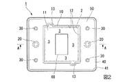
図2は、収納トレイ1の一実施形態を示す平面図である。図2に示すように、収納トレイ1は、平坦に形成された主面50と、主面50に対し裏側に向かって凹む収納用凹部10、嵌合用凹部20、並びに補強用凹部30と、主面50の最外周縁において表側から裏側に向かって延びる縁部40と、を有している。
また、図3は、図2の収納トレイ1の平面図において、A−A方向の矢視断面図を示したものである。図3に示すように、本発明の収納トレイ1は、収納用凹部10の底面11の表側に第1の支持部材60が配設され、裏側に第2の支持部材70が配設されている。
FIG. 2 is a plan view showing an embodiment of the
FIG. 3 is a cross-sectional view taken along the line AA in the plan view of the
また、図2、及び図3に示すように、本実施形態の収納トレイ1において、主面50は矩形状に形成されており、長手方向の中央に収納用凹部10が形成されている。長手方向の両側の端部近傍には、それぞれ、一つの嵌合用凹部20と、2つの補強用凹部30が形成されている。
また、収納用凹部10、嵌合用凹部20、補強用凹部30は、その側壁が下方向に窄まるテーパ形状となっている。また、縁部40は、下方向に広がるテーパ形状となっている。このようなテーパ形状を有することにより、収納用凹部10、嵌合用凹部20、補強用凹部30、並びに縁部40は、収納トレイ1を重ねた時に表面側と裏面側とで嵌合可能となる嵌合構造を形成している。
したがって、本発明に係わる収納トレイ1は、このような嵌合構造が形成されていることから、複数の収納トレイ1をコンパクトに積み重ねることができる。また、このようなテーパ形状を有することによって、本発明に係わる収納トレイ1を、真空成型法で成型加工する時に、金型から成型品を取り外すことが容易になる。
As shown in FIGS. 2 and 3, in the
Moreover, the recessed
Therefore, since the
また、図2、及び図3において、収納トレイ1の嵌合用凹部20は、主面50の短手方向の中央であって、長手方向の両端部近傍にそれぞれ円形に窪んで形成されている。嵌合用凹部20は、板状部品2を挟んで収納トレイ1を重ねた場合に、互いの嵌合用凹部20同士が重なりあって、重なり合った収納トレイ1同士がずれることを防ぐために十分な深さとなっている。嵌合用凹部20の形状は円形に限らず、四辺形や溝形状としても良い。
In FIGS. 2 and 3, the
また、収納トレイ1の補強用凹部30は、主面50の四隅に形成されている。補強用凹部30は、主面50の強度を確保するために設けられている。本実施形態の補強用凹部30は、円形に窪んだ形状を有しているが、細長い溝形状にする等して特定の方向に対して強度を高める形状としても良い。
また、収納トレイ1の補強用凹部30は、溝を深くすることで、嵌合用凹部20の役割を兼用して果たすことができる。この場合は、嵌合用凹部20を略しても良い。
The reinforcing recesses 30 of the
The reinforcing
また、収納トレイ1の縁部40は、主面50の最外周縁に形成されており、その下方先端部には耳部41が形成されている。収納トレイ1の強度を高めると共に、平坦な面に安定して載置する為に設けられている。また、縁部40を十分な高さに形成することで、板状部品2を挟んで収納トレイ1を積み重ねた際に横ずれを防ぎ安定性を高めることができる。
Further, the
また、収納トレイ1の収納用凹部10は、四辺形の板状部品2の外形に沿った形状を有している。収納用凹部10は、四辺形の底面11と、底面11の各辺から主面50に向かって上方に延びる壁部12とを有している。
また、壁部12の一部には、外側に湾曲して広がった掴み代13が形成されている。掴み代13が形成されている部分では、収納用凹部10に収納された板状部品2の外形と壁部12との距離が広くなる。したがって、掴み代13に指を入れることで、板状部品2の縁に指を掛けることができ、作業者は収納用凹部10から容易に板状部品2を取り出すことができる。なお、掴み代13の位置は、壁部12の一部であれば何れであってもよく、例えば平面視における収納用凹部10の四隅に配されていても良い。
また、壁部12は、掴み代13が形成された部分を除いて板状部品2の外形に沿っているため、板状部品2が収納用凹部10に収納された状態で、面方向に板状部品2が移動することを抑制する。
The
In addition, a gripping
Further, since the
また、図2、及び図3に示すように、収納用凹部10の底面11の中央部の近傍には、第1の支持部材60が固着されている。また、底面11の裏側であって、第1の支持部材60と対向する位置に第1の支持部材60と同形状を有する第2の支持部材70が固着されている。
Further, as shown in FIGS. 2 and 3, a
また、本発明に係わる収納トレイ1に配設されている、第1の支持部材60と、第2の支持部材70は、一定の厚みを有する板状に形成されている。第1の支持部材60と、第2の支持部材70は、クッション材からなることが好ましい。本発明に係わる収納トレイ1の、第1の支持部材60、及び第2の支持部材70に使用されるクッション材としては、特に限定されないが、例えばポリウレタン樹脂、ポリエチレン樹脂、アクリル樹脂、ポリイミド樹脂等の合成樹脂を発泡成形して作られるポリウレタンフォーム、ポリエチレンフォーム、アクリルフォーム、ポリイミドフォームなどからなるクッション性を有するスポンジを好適に用いることができる。
また、第1の支持部材60、及び第2の支持部材70に使用されるクッション材としては、内部に空気を封入した1つ又は複数のエアバッグからなるクッション性を有する緩衝材を用いても良い。
これらのクッション材の中でも、本発明の収納トレイ1に係わる第1の支持部材60、及び第2の支持部材70に使用されるクッション材としては、優れた可撓性とクッション性を有するポリウレタンフォームからなるスポンジを使用するのが特に好ましい。
Moreover, the
Further, as a cushioning material used for the
Among these cushion materials, as a cushion material used for the
また、第1の支持部材60と、第2の支持部材70は、収納用凹部10の底面11の表側と裏側とに、それぞれ固着部材により固着されている。固着部材としては、両面接着テープ、両面粘着テープ、接着剤、粘着剤、ホットメルトからなる部材群から選択された1種以上の部材を使用しても良い。接着剤、粘着剤やホットメルトの塗布は、第1の支持部材60と、第2の支持部材70の面全体に行っても良く、また、第1の支持部材60と、第2の支持部材70の四隅などに局所的に行っても良い。
収納用凹部10の底面11には、第1の支持部材60と、第2の支持部材70を固着する際に、作業者が第1の支持部材60と、第2の支持部材70の位置決めを行い易いようにマーキングとしての凸部、凹部、又は溝などが形成されていても良い。
Further, the
The operator positions the
また、第1の支持部材60と、第2の支持部材70は、その四方と収納用凹部10の壁部12の間に隙間3を設けて配置されている。これにより、第1の支持部材60と、第2の支持部材70は、板状部品2の周縁部2cを避けるように、周縁部2cより内側を支持できる。板状部品2の周縁部2cには、他部材が組み付けられて、主面部2aに対して厚みが大きくなる。周縁部2cを避けるように、第1の支持部材60と、第2の支持部材70を配置することで、周縁部2cを浮かせた状態で板状部品2を支持できる。
Further, the
また、第1の支持部材60と、第2の支持部材70は、板状部品2の特殊鍍金部2bに対応する形状とすることが好ましい。これによって、上下から収納トレイ1に挟まれて収納された板状部品2の特殊鍍金部2bは、第1の支持部材60と、第2の支持部材70によって完全に覆われることになる。したがって、保管時や移動時に板状部品2の特殊鍍金部2bに傷が生じたり、埃等が付着したりすることを防止できる。
Moreover, it is preferable that the
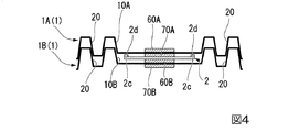
図4に、2つ以上の収納トレイが垂直方向に積み重ねられ、上下に隣接する2つの収納トレイ1の間に挟み込まれた板状部品2の状態を説明する断面図を示す。図4は、収納トレイ1の2つの嵌合用凹部20を横切る直線に沿って断面を取っている。
図4においては、分かり易さのために、上下に隣接する2つの収納トレイのうち、上方の収納トレイ1とその構成要素の符号の末尾にAを付す。即ち、上方の収納トレイ1Aの収納用凹部10Aには、第1の支持部材60Aと第2の支持部材70Aが設けられている。同様に、上下に隣接する2つの収納トレイのうち、下方の収納トレイ1と構成要素の符号の末尾にBを付す。即ち、下方の収納トレイ1Bの収納用凹部10Bには、第1の支持部材60Bと第2の支持部材70Bが設けられている。以下、これらの符号を使用して説明を行う。
FIG. 4 is a cross-sectional view illustrating a state of the plate-
In FIG. 4, for easy understanding, A is added to the end of the reference numerals of the
また、本発明において、板状部品2は、2つ以上の収納トレイが垂直方向に積み重ねられ、上下に隣接する2つの収納トレイ1A、1Bのうち、下方の収納トレイ1Bの第1の支持部材60Bと、隣接する上方の収納トレイ1Aの第2の支持部材70Aとによって挟み込まれて支持されている。また、第1の支持部材60B及び第2の支持部材70Aは、共にクッション材からなる。したがって、板状部品2は、収納トレイ1A、1Bに収納された状態で姿勢が保持され、車両による運搬などにより振動が加わっても、板状部品2に衝撃が伝わりにくく、振動による位置ずれや、振動摩擦による損傷が生じにくい。
In the present invention, the plate-
さらに、本発明に係わる収納トレイに配設されている、第1の支持部材60B及び第2の支持部材70Aは、クッション材であるために、板状部品2に押し当てられることで板状部品2の表面形状に沿って変形する。これによって、第1の支持部材60B及び第2の支持部材70Aと板状部品2は滑りにくくなり、挟み込まれた状態の板状部品2は振動などを受けても位置ズレしにくい。したがって、車両による運搬時などの垂直方向の振動を受けた場合であっても、板状部品2が収納用凹部10の壁部12に衝突することを抑制し、板状部品2が外部応力により塑性変形することから保護できる。
Furthermore, since the
図4に示すように、板状部品2は、その中央部の近傍(より具体的には、図1に示す特殊鍍金部2b)が、上下に隣接する2つの収納トレイ(1A、1B)の第1の支持部材60Bと第2の支持部材70Aとによって挟まれ支持されている。したがって、板状部品2の周縁部2cは、収納トレイ1A、1Bに接触することなく中空に浮いた状態となっており、収納トレイ1A、1Bに当接しない。周縁部2cが、収納トレイ1A、1Bと接触させることで傷が生じる虞がある繊細な部位である場合に、周縁部2cに傷が生じることを防止できる。
加えて、周縁部2cは、上下に隣接する2つの収納トレイ1A、1Bと、厚さ方向の一定の隙間をあけて支持された状態となる。したがって、板状部品2の周縁部2cに他の部品(周縁部品2d)を積層した半組品に対しても、上下に隣接する2つの収納トレイ1A、1Bを共通して使用できる。
As shown in FIG. 4, the plate-
In addition, the
図4に示した、上下に隣接する2つの収納トレイ1A、1Bにおいて、収納トレイ1Bの第1の支持部材60Bと、収納トレイ1Aの第2の支持部材70Aとは、いずれもクッション材からなるため、板状部品2や上方の収納トレイ1Aの重みによって圧縮されている。第1の支持部材60及び第2の支持部材70は、さらに板状部品2や収納トレイ1を積み重ねた場合であっても、周縁部2cが中空に浮いた状態となるように、最も圧縮された状態であっても、周縁部2cと収納トレイ1A、1Bの構造部材との間に、十分な隙間が形成されるような厚みとすることが好ましい。
なお、第1の支持部材60Aの厚みと、第2の支持部材70Aの厚みとは、必ずしも同じでなくても良い。板状部品2の、周縁部2cに積層する周縁部品2dの厚さ及び積層する方向に応じて、一方の支持部材の厚みを厚くして、周縁部品2dが収納トレイ1Aの構造部材、及び収納トレイ1Bの構造部材に、接触しないように構成することが好ましい。
In the two
Note that the thickness of the
図4に示した、上下に隣接する2つの収納トレイの間に挟み込まれた板状部品2は、下方の収納トレイ1Bの収納用凹部10Bにおいて、第1の支持部材60B上に載置され、さらに別の収納トレイ1Aを上方から被せることで、2つの収納トレイ1A、1Bに収納される。さらに、上方の収納トレイ1Aの収納用凹部10Aに、さらに別の板状部品2を搭載し、さらに別の収納トレイ1を積層してくことを繰り返して、複数の板状部品2を次々と収納できる。
上下に隣接する2つの収納トレイ1A、1Bにおいて、上方に積み重ねられた収納トレイ1Aは蓋の役割を果たす。したがって、板状部品2に埃等の異物が付着することを抑制できる。また、別途、蓋部材を設ける場合と比較して、蓋部材の開閉を行うことなく収納トレイ1A、1Bから板状部品2を取り出すことができる。したがって、板状部品2の製造工程、及び加工工程において、ロボットアームによる収納トレイ1からの、板状部品2の自動取り出しが容易に実現できる。
The plate-
In the two
以上のとおり、本発明の一実施形態を説明したが、各実施形態における各構成及びそれらの組み合わせ等は一例であり、本発明の趣旨から逸脱しない範囲内で、構成の付加、省略、置換、及びその他の変更が可能である。また、本発明は実施形態によって限定されることはない。 As described above, one embodiment of the present invention has been described. However, each configuration in each embodiment and combinations thereof are examples, and addition, omission, replacement, and the like of the configuration are within the scope of the present invention. And other changes are possible. Further, the present invention is not limited by the embodiment.
1、1A、1B…収納トレイ、2…板状部品、2a…主面部、2b…特殊鍍金部、2c…周縁部、2d…周縁部品、3…隙間、10、10A、10B…収納用凹部、11…底面、12…壁部、13…掴み代、20…嵌合用凹部、30…補強用凹部、40…縁部、41…耳部、50…主面、60、60A、60B…第1の支持部材、70、70A、70B…第2の支持部材
DESCRIPTION OF
Claims (7)
前記収納トレイが、合成樹脂材料を用いた真空成型法又は圧空成型法により一体成型加工され、略均一な厚さの一枚の合成樹脂板に凹凸が形成された形状を有してなり、
前記板状部品の外縁部に沿った形状の収納用凹部と、
前記収納用凹部の底面の少なくとも一部に設けられた第1の支持部材と、
前記底面の裏面側であって前記第1の支持部材と対応する位置に設けられた第2の支持部材と、
長手方向の両側の端部近傍には、それぞれ少なくとも1つの嵌合用凹部と、を有し、
前記収納用凹部、及び前記嵌合用凹部は、2つ以上の前記収納トレイを、前記第1の支持部材の上に前記板状部品を載置した状態で重ねた時に、前記底面の表面側と裏面側とで嵌合可能となる嵌合構造を形成していることを特徴とする収納トレイ。 A rectangular storage tray for storing plate-shaped components,
The storage tray is integrally molded by a vacuum molding method or a pressure molding method using a synthetic resin material, and has a shape in which irregularities are formed on a single synthetic resin plate having a substantially uniform thickness,
A concave portion for storing along the outer edge of the plate-shaped component;
A first support member provided on at least a part of the bottom surface of the recess for storage;
A second support member provided at a position corresponding to the first support member on the back side of the bottom surface;
In the vicinity of the ends on both sides in the longitudinal direction, each has at least one fitting recess,
The housing recess, and said fitting recess, two or more of the storage tray, when stacked while placing the plate-shaped parts on the first support member, and the surface side of the bottom surface A storage tray having a fitting structure that can be fitted to the back side.
Priority Applications (1)
| Application Number | Priority Date | Filing Date | Title |
|---|---|---|---|
| JP2014159719A JP6478377B2 (en) | 2014-08-05 | 2014-08-05 | Storage tray |
Applications Claiming Priority (1)
| Application Number | Priority Date | Filing Date | Title |
|---|---|---|---|
| JP2014159719A JP6478377B2 (en) | 2014-08-05 | 2014-08-05 | Storage tray |
Publications (2)
| Publication Number | Publication Date |
|---|---|
| JP2016037292A JP2016037292A (en) | 2016-03-22 |
| JP6478377B2 true JP6478377B2 (en) | 2019-03-06 |
Family
ID=55528728
Family Applications (1)
| Application Number | Title | Priority Date | Filing Date |
|---|---|---|---|
| JP2014159719A Active JP6478377B2 (en) | 2014-08-05 | 2014-08-05 | Storage tray |
Country Status (1)
| Country | Link |
|---|---|
| JP (1) | JP6478377B2 (en) |
Family Cites Families (11)
| Publication number | Priority date | Publication date | Assignee | Title |
|---|---|---|---|---|
| JPS593836U (en) * | 1982-07-01 | 1984-01-11 | 日通商事株式会社 | Pallet for cardboard cases |
| JPS60116250U (en) * | 1984-01-11 | 1985-08-06 | 太陽誘電株式会社 | Electrical parts storage device |
| US4511038A (en) * | 1984-01-30 | 1985-04-16 | Ekc Technology, Inc. | Container for masks and pellicles |
| JPH05170275A (en) * | 1991-12-16 | 1993-07-09 | Hitachi Ltd | Semiconductor device holding tray |
| JPH0711539U (en) * | 1993-07-28 | 1995-02-21 | 光永通商株式会社 | Container |
| JP2886822B2 (en) * | 1996-06-03 | 1999-04-26 | 岐阜プラスチック工業株式会社 | Transport pallets |
| JP3976222B2 (en) * | 1999-09-08 | 2007-09-12 | 大日本インキ化学工業株式会社 | Plastic pallet |
| JP2007281052A (en) * | 2006-04-04 | 2007-10-25 | Miraial Kk | Thin plate housing container |
| JP4883627B2 (en) * | 2007-01-24 | 2012-02-22 | ミライアル株式会社 | Wafer storage container with cushion sheet |
| JP2008306111A (en) * | 2007-06-11 | 2008-12-18 | Shin Etsu Polymer Co Ltd | Substrate storage tray |
| JP5727428B2 (en) * | 2012-08-31 | 2015-06-03 | 日本特殊陶業株式会社 | Fuel cell with separator and fuel cell |
-
2014
- 2014-08-05 JP JP2014159719A patent/JP6478377B2/en active Active
Also Published As
| Publication number | Publication date |
|---|---|
| JP2016037292A (en) | 2016-03-22 |
Similar Documents
| Publication | Publication Date | Title |
|---|---|---|
| JP4883627B2 (en) | Wafer storage container with cushion sheet | |
| CN109311557B (en) | Tray and packaging device | |
| EP2703309B1 (en) | Thin panel conveyance unit | |
| JP5470060B2 (en) | Storage tray | |
| JP6478377B2 (en) | Storage tray | |
| US9012052B2 (en) | Battery pack including an adhesion sheet | |
| KR100748455B1 (en) | Optical element reception case | |
| JP3203897U (en) | Storage case and tray | |
| JP3193714U (en) | Storage tray | |
| JP6922894B2 (en) | Packing body and manufacturing method of packing body | |
| JP2010163177A (en) | Protector of rolled product and packing material using the same | |
| JP3193715U (en) | Storage case | |
| JP7061857B2 (en) | Ring spacer | |
| JP6478376B2 (en) | Storage case | |
| JP5207478B2 (en) | Container using synthetic resin sheet and non-woven fabric laminated sheet and container molding method | |
| JP2011207483A (en) | Glass plate pallet, glass plate loading method, glass plate pack, and method for taking out glass plate | |
| JP2007230585A (en) | Tray | |
| JP4866702B2 (en) | Storage container | |
| JP3181222U (en) | Packing material | |
| JP5076386B2 (en) | Packing container | |
| JP5286993B2 (en) | Corner pad | |
| JP6357898B2 (en) | Packing method for plate | |
| WO2023162638A1 (en) | Glass plate packaging body and glass plate dual-layer packaging body | |
| JP4612376B2 (en) | Packing material | |
| JP2024047374A (en) | Packaging Equipment |
Legal Events
| Date | Code | Title | Description |
|---|---|---|---|
| A621 | Written request for application examination |
Free format text: JAPANESE INTERMEDIATE CODE: A621 Effective date: 20170515 |
|
| A977 | Report on retrieval |
Free format text: JAPANESE INTERMEDIATE CODE: A971007 Effective date: 20180213 |
|
| A131 | Notification of reasons for refusal |
Free format text: JAPANESE INTERMEDIATE CODE: A131 Effective date: 20180220 |
|
| A521 | Request for written amendment filed |
Free format text: JAPANESE INTERMEDIATE CODE: A523 Effective date: 20180417 |
|
| A131 | Notification of reasons for refusal |
Free format text: JAPANESE INTERMEDIATE CODE: A131 Effective date: 20180828 |
|
| A521 | Request for written amendment filed |
Free format text: JAPANESE INTERMEDIATE CODE: A523 Effective date: 20181010 |
|
| RD03 | Notification of appointment of power of attorney |
Free format text: JAPANESE INTERMEDIATE CODE: A7423 Effective date: 20181130 |
|
| TRDD | Decision of grant or rejection written | ||
| A01 | Written decision to grant a patent or to grant a registration (utility model) |
Free format text: JAPANESE INTERMEDIATE CODE: A01 Effective date: 20190108 |
|
| A61 | First payment of annual fees (during grant procedure) |
Free format text: JAPANESE INTERMEDIATE CODE: A61 Effective date: 20190204 |
|
| R150 | Certificate of patent or registration of utility model |
Ref document number: 6478377 Country of ref document: JP Free format text: JAPANESE INTERMEDIATE CODE: R150 |
|
| R250 | Receipt of annual fees |
Free format text: JAPANESE INTERMEDIATE CODE: R250 |
|
| R250 | Receipt of annual fees |
Free format text: JAPANESE INTERMEDIATE CODE: R250 |
|
| R250 | Receipt of annual fees |
Free format text: JAPANESE INTERMEDIATE CODE: R250 |