JP6478112B2 - Method for producing non-aqueous electrolyte secondary battery - Google Patents
Method for producing non-aqueous electrolyte secondary battery Download PDFInfo
- Publication number
- JP6478112B2 JP6478112B2 JP2015141077A JP2015141077A JP6478112B2 JP 6478112 B2 JP6478112 B2 JP 6478112B2 JP 2015141077 A JP2015141077 A JP 2015141077A JP 2015141077 A JP2015141077 A JP 2015141077A JP 6478112 B2 JP6478112 B2 JP 6478112B2
- Authority
- JP
- Japan
- Prior art keywords
- battery
- battery assembly
- temperature aging
- negative electrode
- temperature
- Prior art date
- Legal status (The legal status is an assumption and is not a legal conclusion. Google has not performed a legal analysis and makes no representation as to the accuracy of the status listed.)
- Active
Links
Images


Classifications
-
- Y—GENERAL TAGGING OF NEW TECHNOLOGICAL DEVELOPMENTS; GENERAL TAGGING OF CROSS-SECTIONAL TECHNOLOGIES SPANNING OVER SEVERAL SECTIONS OF THE IPC; TECHNICAL SUBJECTS COVERED BY FORMER USPC CROSS-REFERENCE ART COLLECTIONS [XRACs] AND DIGESTS
- Y02—TECHNOLOGIES OR APPLICATIONS FOR MITIGATION OR ADAPTATION AGAINST CLIMATE CHANGE
- Y02E—REDUCTION OF GREENHOUSE GAS [GHG] EMISSIONS, RELATED TO ENERGY GENERATION, TRANSMISSION OR DISTRIBUTION
- Y02E60/00—Enabling technologies; Technologies with a potential or indirect contribution to GHG emissions mitigation
- Y02E60/10—Energy storage using batteries
-
- Y—GENERAL TAGGING OF NEW TECHNOLOGICAL DEVELOPMENTS; GENERAL TAGGING OF CROSS-SECTIONAL TECHNOLOGIES SPANNING OVER SEVERAL SECTIONS OF THE IPC; TECHNICAL SUBJECTS COVERED BY FORMER USPC CROSS-REFERENCE ART COLLECTIONS [XRACs] AND DIGESTS
- Y02—TECHNOLOGIES OR APPLICATIONS FOR MITIGATION OR ADAPTATION AGAINST CLIMATE CHANGE
- Y02P—CLIMATE CHANGE MITIGATION TECHNOLOGIES IN THE PRODUCTION OR PROCESSING OF GOODS
- Y02P70/00—Climate change mitigation technologies in the production process for final industrial or consumer products
- Y02P70/50—Manufacturing or production processes characterised by the final manufactured product
Description
本発明は、非水電解質二次電池の製造方法に関する。 The present invention relates to a method for manufacturing a nonaqueous electrolyte secondary battery.
リチウム二次電池等の非水電解質二次電池は、近年、パソコンや携帯端末等のいわゆるポータブル電源や車両駆動用電源として用いられている。特に、軽量で高エネルギー密度が得られるリチウム二次電池(リチウムイオン二次電池)は、電気自動車、ハイブリッド自動車等の車両の駆動用高出力電源として好ましく用いられている。 In recent years, nonaqueous electrolyte secondary batteries such as lithium secondary batteries have been used as so-called portable power sources such as personal computers and portable terminals and vehicle power sources. In particular, a lithium secondary battery (lithium ion secondary battery) that is lightweight and obtains a high energy density is preferably used as a high-output power source for driving vehicles such as electric vehicles and hybrid vehicles.
この種の非水電解質二次電池の製造においては、一般的に、正極と負極とがセパレータを介して対向した構造の電極体と、電解質(典型的には、電解液)と、を用いて電池組立体を構築した後で、当該電池組立体を電池として実際に使用可能な状態に調整するために、上記正極と上記負極の間に電流を付与する初期充電処理が行われる。そして、かかる初期充電を行った後の電池組立体を所定の温度条件下(典型的には高温環境下)でエージング処理を施した後、該電池組立体の性能確認(例えばIV抵抗や自己放電特性の検査)を行うことが一般的である。上記自己放電特性の検査では、所定の充電状態に調整した電池組立体を一定期間放置し、当該放置(自己放電)期間の電圧降下量を計測することで、該電池組立体内に微小な内部短絡が生じているか否かを判定する。特許文献1には、初期充電処理後の電池組立体を所定の温度で所定時間エージング処理する技術に関する記載がある。 In the manufacture of this type of non-aqueous electrolyte secondary battery, generally, an electrode body having a structure in which a positive electrode and a negative electrode face each other with a separator interposed therebetween, and an electrolyte (typically, an electrolytic solution) are used. After the battery assembly is constructed, an initial charging process for applying a current between the positive electrode and the negative electrode is performed in order to adjust the battery assembly to a state where it can actually be used as a battery. Then, the battery assembly after the initial charging is subjected to an aging process under a predetermined temperature condition (typically in a high temperature environment), and then the performance of the battery assembly is confirmed (for example, IV resistance or self-discharge). It is common to perform inspection of characteristics). In the self-discharge characteristic test, a battery assembly adjusted to a predetermined charge state is left for a certain period, and a voltage drop during the left-handed (self-discharge) period is measured. Whether or not has occurred. Japanese Patent Application Laid-Open No. 2004-228561 describes a technique for performing an aging process on a battery assembly after an initial charging process at a predetermined temperature for a predetermined time.
ところで、かかる非水電解質二次電池の製造にあたっては、外部(例えば製造装置の構成部材)から銅や鉄等の金属異物が混入する場合がある。混入した金属異物は、電池の充電によって溶解電位を上回るとイオン化され(例えばCu2+、Fe2+となって)、電解質中に溶出する。この金属イオンは、一般的に負極側に向かって移動し、負極上で還元されて析出する場合がある。かかる金属の析出物がセパレータを貫通して正極に到達すると、電池内部に微小な短絡(所謂、内部短絡)が発生する虞がある。内部短絡が発生すると電池性能が悪化(例えばエネルギー密度が低下)する等の不具合が生じるため、好ましくない。 By the way, when manufacturing such a nonaqueous electrolyte secondary battery, metal foreign matters such as copper and iron may be mixed from the outside (for example, a component of a manufacturing apparatus). The mixed metal foreign matter is ionized (for example, Cu 2+ , Fe 2+ ) when it exceeds the dissolution potential by charging the battery, and is eluted into the electrolyte. This metal ion generally moves toward the negative electrode side and may be reduced and deposited on the negative electrode. When such metal deposits penetrate the separator and reach the positive electrode, there is a possibility that a minute short circuit (so-called internal short circuit) may occur inside the battery. The occurrence of an internal short circuit is not preferable because the battery performance deteriorates (for example, the energy density decreases).
非水電解質二次電池を製造するにあたり、電池組立体を構築し、初期充電を行った後で上記エージング処理を行うことで、上記電池組立体内部に混入した金属異物を予め負極上に析出させることができる。これにより、電池使用時において、上記電池内部に混入した金属異物に起因する内部短絡が発生することを防ぐことができる。
一方で、エージング処理時に内部短絡が生じた電池は、その後の性能確認(典型的には自己放電特性の検査)において製造工程における不都合品と判定されるため、製造工程における不良率が増大する虞がある。したがって、電池を量産する観点(製造効率の観点)からは、エージング処理時における上記電池組立体の内部に混入した金属異物に起因した内部短絡の発生を低減することが望まれている。
In manufacturing the non-aqueous electrolyte secondary battery, the battery assembly is constructed, and after the initial charge, the aging treatment is performed to deposit the metal foreign matter mixed in the battery assembly in advance on the negative electrode. be able to. Thereby, when the battery is used, it is possible to prevent the occurrence of an internal short circuit due to the metal foreign matter mixed in the battery.
On the other hand, a battery in which an internal short circuit has occurred during the aging process is determined as an inferior product in the manufacturing process in subsequent performance confirmation (typically, inspection of self-discharge characteristics), which may increase the defect rate in the manufacturing process. There is. Therefore, from the viewpoint of mass production of batteries (from the viewpoint of manufacturing efficiency), it is desired to reduce the occurrence of internal short circuits due to metal foreign matters mixed in the battery assembly during the aging process.
本発明は、かかる点に鑑みてなされたものであり、その目的は、信頼性の高い(電池内に混入した金属異物の析出に起因する内部短絡が生じ難い)非水電解質二次電池を効率よく量産し得る方法を提供することである。 The present invention has been made in view of such a point, and the object thereof is to improve the efficiency of a highly reliable non-aqueous electrolyte secondary battery (in which an internal short circuit due to precipitation of metallic foreign matter mixed in the battery is unlikely to occur). It is to provide a method that can be mass-produced well.
上記目的を実現すべく、本発明により、非水電解質二次電池を製造する方法であって、以下の(i)〜(v)の工程を包含する非水電解質二次電池の製造方法が提供される。即ち、ここで開示される製造方法は、
(i)正極と、負極と、非水電解質と、を用いて電池組立体を構築する工程;
(ii)上記電池組立体を初期充電する工程;
(iii)上記初期充電後の電池組立体を15℃以上30℃以下で6時間以上放置する低温エージング工程;
(iv)上記低温エージング工程後の電池組立体を、60℃で少なくとも20時間放置する高温エージング工程;および
(v)上記高温エージング工程後の電池組立体を自己放電させる工程;を包含する。
In order to achieve the above object, according to the present invention, there is provided a method for producing a non-aqueous electrolyte secondary battery, which comprises the following steps (i) to (v): Is done. That is, the manufacturing method disclosed here is:
(I) a step of constructing a battery assembly using a positive electrode, a negative electrode, and a non-aqueous electrolyte;
(Ii) initial charging the battery assembly;
(Iii) a low temperature aging step in which the battery assembly after the initial charging is left at 15 ° C. or higher and 30 ° C. or lower for 6 hours or longer;
(Iv) a high temperature aging step in which the battery assembly after the low temperature aging step is allowed to stand at 60 ° C. for at least 20 hours; and (v) a step of self-discharging the battery assembly after the high temperature aging step.
エージングを行う温度を低くするほど、電池組立体内部に混入した金属異物が非水電解質中に溶解する速度を遅くすることができる。これにより、イオン化した金属異物(金属イオン)は非水電解質中を拡散し、負極上に薄く析出される。
即ち、上記低温エージングを行うことで、金属異物が存在した部分に対向する負極上に当該金属異物に由来する析出物が集中的に析出することを軽減し、当該負極上に析出した析出物によってセパレータが貫通して内部短絡が発生することを抑制することが出来る。これにより、製造工程における不都合品の発生率(即ち製造工程における不良率)を低減し、電池の製造効率を向上することができる。
また、上記低温エージングにおいて上記電池組立体内部に混入した金属異物が溶け残った場合であっても、上記高温エージングを行うことで、当該金属異物を非水電解質中に溶解し、負極上に予め析出しておくことができる。これにより、電池使用時に内部短絡が発生することを抑制することができる。
以上に述べたとおり、本発明によると、電池使用時における内部短絡の発生が抑制された非水電解質二次電池を、製造工程上の不良率を抑制して効率よく量産することができる。
The lower the temperature at which aging is performed, the slower the rate at which metal foreign matter mixed inside the battery assembly dissolves in the non-aqueous electrolyte. Thereby, the ionized foreign metal (metal ion) diffuses in the non-aqueous electrolyte and is thinly deposited on the negative electrode.
That is, by performing the low-temperature aging, it is possible to reduce the concentration of precipitates derived from the metal foreign matter on the negative electrode facing the portion where the metal foreign matter is present, and by the precipitate deposited on the negative electrode. It is possible to suppress the occurrence of an internal short circuit through the separator. Thereby, the incidence rate of inferior goods in a manufacturing process (namely, the defective rate in a manufacturing process) can be reduced, and the manufacturing efficiency of a battery can be improved.
Further, even if the metal foreign matter mixed inside the battery assembly remains undissolved in the low temperature aging, by performing the high temperature aging, the metal foreign matter is dissolved in the non-aqueous electrolyte and is previously formed on the negative electrode. It can be deposited. Thereby, it can suppress that an internal short circuit generate | occur | produces at the time of battery use.
As described above, according to the present invention, it is possible to efficiently mass-produce nonaqueous electrolyte secondary batteries in which the occurrence of internal short circuits during use of the battery is suppressed while suppressing the defective rate in the manufacturing process.
以下、適宜図面を参照しながら、本発明の一実施形態に係る非水電解質二次電池の製造方法を詳細に説明する。なお、本明細書において特に言及している事項以外の事柄であって本発明の実施に必要な事柄は、当該分野における従来技術に基づく当業者の設計事項として把握され得る。本発明は、本明細書に開示されている内容と当該分野における技術常識とに基づいて実施することができる。なお、以下の図面において、同じ作用を奏する部材・部位には同じ符号を付して説明し、重複する説明は省略または簡略化することがある。また、各図における寸法関係(長さ、幅、厚さ等)は必ずしも実際の寸法関係を反映するものではない。 Hereinafter, a method for manufacturing a nonaqueous electrolyte secondary battery according to an embodiment of the present invention will be described in detail with reference to the drawings as appropriate. Note that matters other than matters specifically mentioned in the present specification and necessary for the implementation of the present invention can be grasped as design matters of those skilled in the art based on the prior art in this field. The present invention can be carried out based on the contents disclosed in this specification and common technical knowledge in the field. In the following drawings, members / parts having the same action are described with the same reference numerals, and redundant descriptions may be omitted or simplified. Further, the dimensional relationship (length, width, thickness, etc.) in each drawing does not necessarily reflect the actual dimensional relationship.
なお、本明細書において「二次電池」とは、繰り返し充放電可能な電池一般をいい、リチウム二次電池、ナトリウム二次電池、ニッケル水素二次電池等のいわゆる化学電池ならびに電気二重層キャパシタ等の物理電池を包含する用語である。また、本明細書において「リチウム二次電池」とは、電荷担体(支持塩、支持電解質)としてリチウムイオンを利用し、正負極間におけるリチウムイオンの移動により充放電する二次電池をいう。 In the present specification, the “secondary battery” generally refers to a battery that can be repeatedly charged and discharged, such as a so-called chemical battery such as a lithium secondary battery, a sodium secondary battery, and a nickel hydride secondary battery, and an electric double layer capacitor. It is a term encompassing the physical battery. In the present specification, the “lithium secondary battery” refers to a secondary battery that uses lithium ions as a charge carrier (supporting salt, supporting electrolyte) and is charged and discharged by the movement of lithium ions between the positive and negative electrodes.
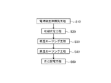
ここで開示される非水電解質二次電池の製造方法は、図1に示すように、電池組立体構築工程(S10)、初期充電工程(S20)、低温エージング工程(S30)、高温エージング工程(S40)、および、自己放電工程(S50)と、を包含する。以下、各工程について説明する。 As shown in FIG. 1, the manufacturing method of the nonaqueous electrolyte secondary battery disclosed here includes a battery assembly construction step (S10), an initial charging step (S20), a low temperature aging step (S30), a high temperature aging step ( S40) and a self-discharge step (S50). Hereinafter, each step will be described.
まず、電池組立体構築工程(S10)について説明する。かかる工程は、正極と、負極と、非水電解質とを用いて電池組立体を構築することを含む。ここで、正極と、負極と、非水電解質は特に限定されず、一般的な非水電解質二次電池で用いられるものと同様のものを特に制限なく使用することができる。特に限定する事を意図するものではないが、ここで開示する電池組立体の典型例を、リチウム二次電池を例にして説明する。なお、リチウム二次電池は一例であり、本発明の技術思想は、その他の電荷担体(例えばナトリウムイオン)を備える他の非水電解質二次電池(例えばナトリウム二次電池)にも適用される。 First, the battery assembly construction step (S10) will be described. Such a process includes constructing a battery assembly using a positive electrode, a negative electrode, and a non-aqueous electrolyte. Here, the positive electrode, the negative electrode, and the nonaqueous electrolyte are not particularly limited, and those similar to those used in a general nonaqueous electrolyte secondary battery can be used without particular limitation. Although not intended to be particularly limited, a typical example of the battery assembly disclosed herein will be described using a lithium secondary battery as an example. The lithium secondary battery is an example, and the technical idea of the present invention is also applied to other non-aqueous electrolyte secondary batteries (for example, sodium secondary batteries) having other charge carriers (for example, sodium ions).
上記電池組立体は、典型的に、正極および負極を用いて電極体を構築し、当該電極体と非水電解質とを電池ケース(外装体)に収容して構築される。上記電池ケースの形状は特に限定されず、例えば円筒形状、立方体形状(箱型)等であり得る。かかる電池ケースには、典型的に、外部接続用の正負極端子と、電池ケース内の内圧を開放するように設定された安全弁と、非水電解質をケース内に注入するための注入口とが設けられている。このような電池ケースの材質としては、例えば、軽量で熱伝導性の良い金属材料(例えばアルミニウム)が好適である。 The battery assembly is typically constructed by constructing an electrode body using a positive electrode and a negative electrode, and housing the electrode body and a non-aqueous electrolyte in a battery case (exterior body). The shape of the battery case is not particularly limited, and may be, for example, a cylindrical shape or a cubic shape (box shape). Such battery cases typically have positive and negative terminals for external connection, a safety valve set to release the internal pressure in the battery case, and an inlet for injecting a nonaqueous electrolyte into the case. Is provided. As a material of such a battery case, for example, a metal material (for example, aluminum) that is lightweight and has good thermal conductivity is suitable.
また、上記電極体は、正極および負極をセパレータを介して重ねあわせて構築される。なお、かかる電極体の構成は特に限定されず、例えば、積層型の電極体(積層電極体)、或いは捲回型の電極体(捲回電極体)であり得る。 The electrode body is constructed by superposing the positive electrode and the negative electrode with a separator interposed therebetween. In addition, the structure of this electrode body is not specifically limited, For example, it can be a laminated electrode body (laminated electrode body) or a wound electrode body (wound electrode body).
上記負極は、負極集電体と、該負極集電体の片面または両面に形成された少なくとも負極活物質を含む負極活物質層とを備える。上記負極集電体としては、例えば銅箔等を好適に使用し得る。上記負極活物質としては、従来からリチウム二次電池に用いられる材料の一種または二種以上を特に限定なく使用することができる。例えば、少なくとも一部にグラファイト構造(層状構造)を含む粒子状(或いは球状、鱗片状)の炭素材料、リチウム遷移金属複合酸化物(例えば、Li4Ti5O12等のリチウムチタン複合酸化物)、リチウム遷移金属複合窒化物等が挙げられる。炭素材料としては、例えば、天然黒鉛、人造黒鉛(人工黒鉛)、難黒鉛化炭素(ハードカーボン)、易黒鉛化炭素(ソフトカーボン)等が挙げられる。或いはまた、コアとしての黒鉛粒子が非晶質(アモルファス)な炭素素材で被覆(コート)された形態のカーボン粒子であってもよい。なお、負極活物質層は、活物質以外の成分、例えばバインダや増粘剤等を含み得る。バインダとしては、スチレンブタジエンラバー(SBR)等を使用し得る。増粘剤としては、例えばカルボキシメチルセルロース(CMC)等を使用し得る。 The negative electrode includes a negative electrode current collector and a negative electrode active material layer including at least a negative electrode active material formed on one or both surfaces of the negative electrode current collector. As said negative electrode collector, copper foil etc. can be used conveniently, for example. As the negative electrode active material, one type or two or more types of materials conventionally used for lithium secondary batteries can be used without any particular limitation. For example, a particulate (or spherical or scale-like) carbon material including a graphite structure (layered structure) at least partially, a lithium transition metal composite oxide (for example, a lithium titanium composite oxide such as Li4Ti5O12), a lithium transition metal composite Nitride etc. are mentioned. Examples of the carbon material include natural graphite, artificial graphite (artificial graphite), non-graphitizable carbon (hard carbon), graphitizable carbon (soft carbon), and the like. Alternatively, carbon particles in a form in which graphite particles as a core are coated (coated) with an amorphous carbon material may be used. Note that the negative electrode active material layer can contain components other than the active material, such as a binder and a thickener. As the binder, styrene butadiene rubber (SBR) or the like can be used. As the thickener, for example, carboxymethyl cellulose (CMC) can be used.
このような負極は、例えば負極活物質と必要に応じて用いられる材料とを適当な溶媒(例えば水)に分散させ、ペースト状(スラリー状)の組成物を調製し、該組成物の適当量を負極集電体の表面に付与した後、乾燥することによって形成することができる。また、必要に応じて適当なプレス処理を施すことによって負極活物質層の性状(例えば、平均厚み、活物質密度、空孔率等)を調整し得る。 For such a negative electrode, for example, a negative electrode active material and a material used as necessary are dispersed in an appropriate solvent (for example, water) to prepare a paste-like (slurry) composition, and an appropriate amount of the composition Can be formed by drying after applying to the surface of the negative electrode current collector. Moreover, the properties (for example, average thickness, active material density, porosity, etc.) of the negative electrode active material layer can be adjusted by performing an appropriate press treatment as necessary.
上記正極は、正極集電体と、該正極集電体の片面または両面に形成された少なくとも正極活物質を含む正極活物質層とを備える。上記正極集電体としては、例えばアルミニウム箔等を好適に使用し得る。上記正極活物質としては、従来からリチウム二次電池に用いられる材料の一種または二種以上を特に限定なく使用することができる。例えば層状構造やスピネル構造等のリチウム複合金属酸化物(例えば、LiNi1/3Co1/3Mn1/3O2、LiNiO2、LiCoO2、LiFeO2、LiMn2O4、LiNi0.5Mn1.5O4、LiFePO4等)が挙げられる。なお、正極活物質層は、活物質以外の成分、例えば導電材やバインダ等を含み得る。導電材としては、アセチレンブラック(AB)等のカーボンブラックやその他(グラファイト等)の炭素材料を好適に使用し得る。バインダとしては、PVdF等を使用し得る。 The positive electrode includes a positive electrode current collector and a positive electrode active material layer including at least a positive electrode active material formed on one or both surfaces of the positive electrode current collector. As said positive electrode electrical power collector, aluminum foil etc. can be used conveniently, for example. As the positive electrode active material, one kind or two or more kinds of materials conventionally used for lithium secondary batteries can be used without any particular limitation. For example, a lithium composite metal oxide such as a layered structure or a spinel structure (for example, LiNi 1/3 Co 1/3 Mn 1/3 O 2 , LiNiO 2 , LiCoO 2 , LiFeO 2 , LiMn 2 O 4 , LiNi 0.5 Mn 1.5 O 4 , LiFePO 4, etc.). Note that the positive electrode active material layer may include components other than the active material, such as a conductive material and a binder. As the conductive material, carbon black such as acetylene black (AB) and other (such as graphite) carbon materials can be suitably used. As the binder, PVdF or the like can be used.
このような正極は、例えば正極活物質と必要に応じて用いられる材料とを適当な溶媒(例えばN−メチル−2−ピロリドン)に分散させ、ペースト状(スラリー状)の組成物を調製し、該組成物の適当量を正極集電体の表面に付与した後、乾燥することによって形成することができる。また、必要に応じて適当なプレス処理を施すことによって正極活物質層の性状(例えば、平均厚み、活物質密度、空孔率等)を調整し得る。 For such a positive electrode, for example, a positive electrode active material and a material used as necessary are dispersed in a suitable solvent (for example, N-methyl-2-pyrrolidone) to prepare a paste-like (slurry) composition, It can be formed by applying an appropriate amount of the composition to the surface of the positive electrode current collector and then drying it. Moreover, the properties (for example, average thickness, active material density, porosity, etc.) of the positive electrode active material layer can be adjusted by performing an appropriate press treatment as necessary.
セパレータとしては、例えばポリエチレン(PE)、ポリプロピレン(PP)、ポリエステル、セルロース、ポリアミド等の樹脂から成る多孔性シート(フィルム)が挙げられる。かかる多孔性シートは、単層構造であってもよく、二層以上の積層構造(例えば、PE層の両面にPP層が積層された三層構造)であってもよい。セパレータの厚み(平均厚み)は特に限定されないが、正極と負極との絶縁性を確保する観点から、10μm以上のものを好適に使用することができる。また、ここで開示する技術によると、厚みの薄いセパレータを用いた場合であっても内部短絡の発生を抑制することができるため、例えば、セパレータの厚み(平均厚み)が30μm未満(典型的には24μm以下)である薄いセパレータを好適に使用することができる。薄いセパレータを用いることで、電池ケース内部の容積に占めるセパレータ体積を減らすことができ、電池の高容量化を実現することができる。 Examples of the separator include a porous sheet (film) made of a resin such as polyethylene (PE), polypropylene (PP), polyester, cellulose, and polyamide. Such a porous sheet may have a single-layer structure or a laminated structure of two or more layers (for example, a three-layer structure in which PP layers are laminated on both sides of a PE layer). Although the thickness (average thickness) of a separator is not specifically limited, The thing of 10 micrometers or more can be used conveniently from a viewpoint of ensuring the insulation of a positive electrode and a negative electrode. Moreover, according to the technique disclosed here, even when a thin separator is used, the occurrence of an internal short circuit can be suppressed. For example, the thickness (average thickness) of the separator is less than 30 μm (typically Is preferably a thin separator having a thickness of 24 μm or less. By using a thin separator, the separator volume occupying the volume inside the battery case can be reduced, and the capacity of the battery can be increased.
非水電解質の性状は特に限定されず、液状、ゲル状、固体状のものでありうる。典型的には、有機溶媒(非水溶媒)中に支持塩を含有する非水電解液を用いることができる。かかる非水電解液は常温(例えば25℃)で液状を呈し、好ましい一態様では、電池の使用環境下(例えば0℃〜60℃の温度環境下)で常に液状を呈する。 The property of the nonaqueous electrolyte is not particularly limited, and may be liquid, gel, or solid. Typically, a nonaqueous electrolytic solution containing a supporting salt in an organic solvent (nonaqueous solvent) can be used. Such a non-aqueous electrolyte exhibits a liquid state at normal temperature (for example, 25 ° C.). In a preferred embodiment, the non-aqueous electrolyte always exhibits a liquid state under a battery usage environment (for example, a temperature environment of 0 ° C. to 60 ° C.).
非水溶媒としては、一般的なリチウム二次電池の電解液に用いられる各種のカーボネート類、エーテル類、エステル類、ニトリル類、スルホン類、ラクトン類等の有機溶媒を用いることができる。具体例として、エチレンカーボネート(EC)、プロピレンカーボネート(PC)、ジエチルカーボネート(DEC)、ジメチルカーボネート(DMC)、エチルメチルカーボネート(EMC)等が例示される。このような非水溶媒は、1種を単独で、あるいは2種以上を適宜組み合わせて用いることができる。
支持塩としては、一般的なリチウム二次電池と同様のものを使用することができる。例えば、LiPF6、LiBF4、LiClO4、LiAsF6等(好ましくはLiPF6)のリチウム塩が挙げられる。このような支持塩は、1種を単独で、または2種以上を組み合わせて用いることができる。また、非水電解質中の支持塩の濃度の好適範囲は0.7mol/L〜1.3mol/L(例えば、1.1mol/L)に設定し得る。
As the non-aqueous solvent, organic solvents such as various carbonates, ethers, esters, nitriles, sulfones, and lactones that are used in an electrolytic solution of a general lithium secondary battery can be used. Specific examples include ethylene carbonate (EC), propylene carbonate (PC), diethyl carbonate (DEC), dimethyl carbonate (DMC), ethyl methyl carbonate (EMC) and the like. Such a non-aqueous solvent can be used individually by 1 type or in combination of 2 or more types as appropriate.
As the supporting salt, the same salt as that of a general lithium secondary battery can be used. For example, a lithium salt of LiPF 6 , LiBF 4 , LiClO 4 , LiAsF 6 or the like (preferably LiPF 6 ) can be used. Such a supporting salt can be used singly or in combination of two or more. Moreover, the suitable range of the density | concentration of the support salt in a nonaqueous electrolyte can be set to 0.7 mol / L-1.3 mol / L (for example, 1.1 mol / L).
なお、上記非水電解質中には、本発明の効果を著しく損なわない限りにおいて、上述した非水溶媒および支持塩以外の成分(添加剤)を含みうる。かかる添加剤として、例えば、被膜形成剤(例えばフルオロスルホン酸リチウム等);ガス発生剤;分散剤;増粘剤;等の各種添加剤を含み得る。 In addition, in the said nonaqueous electrolyte, unless the effect of this invention is impaired remarkably, components (additives) other than the nonaqueous solvent mentioned above and supporting salt may be included. Examples of such additives may include various additives such as a film forming agent (for example, lithium fluorosulfonate); a gas generating agent; a dispersant; a thickener;
次に、初期充電工程(S20)について説明する。かかる初期充電工程では、上記電池組立体を充電処理する。典型的には、該組立体の正極(正極端子)と負極(負極端子)との間に外部電源を接続し、所定の電圧まで充電を行う。かかる充電処理は、定電流充電(CC充電)により行ってもよく、或いは定電流定電圧充電(CCCV充電)により行ってもよい。定電流充電時の充電レートは特に限定されないが、例えば0.1C〜10C(典型的には1C〜3C)程度とすればよい。ここで、「1C」とは、理論容量より予測した電池容量(Ah)を一時間で充電することができる電流値いうこととする、例えば電池容量が4Ahの場合は1C=4Aである。
また、充電処理工程における正負極端子間の電圧(典型的には最高到達電圧)は、使用する活物質材料や非水溶媒の種類等にも依るが、電池組立体のSOC(State of Charge:充電深度)が凡そ80%以上(典型的には90〜105%)の範囲にあるときに示し得る電圧範囲とすればよい。例えば、4.2Vで満充電となる電池では、およそ3.8V〜4.2V(例えば3.95V〜4.05V)程度とすることができる。なお、上記充電処理は一回でもよく、例えば放電処理工程を挟んで、二回以上繰り返し行うこともできる。
Next, the initial charging step (S20) will be described. In the initial charging step, the battery assembly is charged. Typically, an external power source is connected between the positive electrode (positive electrode terminal) and the negative electrode (negative electrode terminal) of the assembly, and charging is performed to a predetermined voltage. Such charging processing may be performed by constant current charging (CC charging), or may be performed by constant current constant voltage charging (CCCV charging). Although the charging rate at the time of constant current charge is not specifically limited, For example, what is necessary is just to be about 0.1C-10C (typically 1C-3C). Here, “1C” refers to a current value that can charge the battery capacity (Ah) predicted from the theoretical capacity in one hour. For example, when the battery capacity is 4 Ah, 1C = 4A.
In addition, the voltage between the positive and negative terminals (typically the highest voltage reached) in the charging process depends on the active material used, the type of non-aqueous solvent, etc., but the SOC (State of Charge) of the battery assembly. A voltage range that can be shown when the charging depth is in the range of about 80% or more (typically 90 to 105%) may be used. For example, in a battery that is fully charged at 4.2 V, it can be set to about 3.8 V to 4.2 V (for example, 3.95 V to 4.05 V). In addition, the said charge process may be performed once, for example, can also be repeatedly performed twice or more on both sides of a discharge process process.
次に、低温エージング工程(S30)について説明する。かかる工程では、上記初期充電工程後の電池組立体を、15℃以上30℃以下の温度条件下に所定時間放置(保持)することを含む。例えば、所定の温度に設定した恒温槽(温度制御恒温槽内)に電池組立体を収容する手段等により、電池組立体を所定の温度条件下に放置(保持)することができる。
ここで、電池組立体を放置(保持)する温度が低すぎると、電池組立体内に混入した金属異物を非水電解質中に溶解するスピードが遅くなりすぎて、当該金属異物の多くが溶け残ってしまう場合がある。かかる溶け残った金属異物は後述する高温エージング工程において非水電解質に溶解されて負極上に局所的に析出しがちであり、内部短絡が発生する原因となり得る好ましくない。また、上記低温エージング工程において電池組立体を放置(保持)する温度が高すぎると、電池組立体内に混入した金属異物が非水電解質中に溶解するスピードが速くなりすぎて、非水電解質中に溶解した金属異物(金属イオン)の非水電解質中への分散が不十分となりがちである。このため、非水電解質中に溶解した金属異物(金属イオン)が負極上に局所的に析出し、内部短絡が発生する虞があるため好ましくない。
Next, the low temperature aging step (S30) will be described. This step includes leaving (holding) the battery assembly after the initial charging step under a temperature condition of 15 ° C. or higher and 30 ° C. or lower for a predetermined time. For example, the battery assembly can be left (maintained) under a predetermined temperature condition by means for accommodating the battery assembly in a constant temperature bath (in a temperature controlled constant temperature bath) set to a predetermined temperature.
Here, if the temperature at which the battery assembly is left (held) is too low, the speed at which the metal foreign matter mixed in the battery assembly is dissolved in the non-aqueous electrolyte is too slow, and most of the metal foreign matter remains undissolved. May end up. Such undissolved metallic foreign matter tends to be dissolved in the non-aqueous electrolyte and locally deposited on the negative electrode in a high-temperature aging process described later, which may cause an internal short circuit. In addition, if the temperature at which the battery assembly is left (held) in the low temperature aging process is too high, the speed at which the metal foreign matter mixed in the battery assembly dissolves in the nonaqueous electrolyte becomes too high, Dispersion of dissolved metal foreign matter (metal ions) in the non-aqueous electrolyte tends to be insufficient. For this reason, since the metal foreign material (metal ion) melt | dissolved in the nonaqueous electrolyte deposits locally on a negative electrode and an internal short circuit may generate | occur | produce, it is unpreferable.
上記低温エージング工程において、電池組立体を上記の温度条件下に6時間以上放置(保持)することで、電池の製造工程において内部短絡の発生を抑制する効果を好適に発揮することができる。かかる低温エージングを行う時間は、6時間以上であれば特に限定されないが、例えば、12時間以上(例えば24時間以上、典型的には48時間以上)とすることができる。なお、電池の製造効率を考慮すると、上記低温エージング工程の時間は例えば96時間以下(典型的には72時間以下)とし得る。 In the low temperature aging process, the battery assembly is allowed to stand (hold) for 6 hours or more under the above temperature condition, so that the effect of suppressing the occurrence of an internal short circuit in the battery manufacturing process can be suitably exhibited. The time for performing such low-temperature aging is not particularly limited as long as it is 6 hours or longer. For example, it can be 12 hours or longer (for example, 24 hours or longer, typically 48 hours or longer). In consideration of the production efficiency of the battery, the time for the low temperature aging step can be, for example, 96 hours or less (typically 72 hours or less).
次に、高温エージング工程(S40)について説明する。かかる工程では、上記低温エージング後の電池組立体を、上記低温エージング工程よりも高温の温度条件下に所定時間放置(保持)することを含む。 Next, the high temperature aging step (S40) will be described. This step includes leaving (holding) the battery assembly after the low temperature aging for a predetermined time under a temperature condition higher than that of the low temperature aging step.
上記高温エージング工程における温度条件および放置時間は特に限定されず、電池の構成等によって適宜調整して設定すればよい。例えば、上記電池組立体を放置(保持)する温度条件は、40℃以上(例えば60℃以上、典型的には上記60℃±3℃)とし得る。かかる高温エージング工程において電池組立体を放置(保持)する温度が高すぎると、電池組立体の構成材料(例えばセパレータ、非水電解質等)が変質(劣化)してしまうため好ましくない。このため、上記高温エージング工程における温度条件は、電池組立体の構成材料のうちで温度上昇により最も変質しやすい材料(典型的にはセパレータ)の耐熱温度以下の温度、例えば、100℃以下、(例えば90℃以下、典型的には80℃以下)とし得る。電池組立体を上記の温度条件(高温条件)で保持する方法としては、従来公知の加熱手段を好ましく用いることができる。例えば、所定の温度に設定した恒温槽(温度制御恒温槽)等の加熱容器内に電池組立体を収容する、或いは、赤外線ヒーター等の加熱手段を用いて電池組立体外部から加熱する等の手段により行うことができる。
また、上記電池組立体を放置(保持)する時間は、例えば10時間以上(典型的には15時間以上)とし得る。かかる電池組立体の放置(保持)時間が長すぎると、電池の製造に要する時間が延長し、製造効率が低下しがちである。このため、例えば200時間以下(典型的には180時間以下、一般的には48時間以下)とし得る。具体的には、20時間(一般的には20時間±2時間)程度、上記の温度条件下に放置(保持)すればよい。
The temperature condition and the standing time in the high temperature aging process are not particularly limited, and may be set as appropriate according to the configuration of the battery. For example, the temperature condition for leaving (holding) the battery assembly may be 40 ° C. or higher (eg, 60 ° C. or higher, typically 60 ° C. ± 3 ° C.). If the temperature at which the battery assembly is left (held) in such a high temperature aging process is too high, the constituent materials of the battery assembly (for example, separators, non-aqueous electrolytes, etc.) are altered (deteriorated), which is not preferable. For this reason, the temperature condition in the high temperature aging step is a temperature lower than the heat resistance temperature of a material (typically a separator) that is most likely to change due to a temperature rise among the constituent materials of the battery assembly, for example, 100 ° C. or lower ( For example, it may be 90 ° C. or lower, typically 80 ° C. or lower). As a method for holding the battery assembly under the above temperature condition (high temperature condition), a conventionally known heating means can be preferably used. For example, the battery assembly is housed in a heating vessel such as a thermostat (temperature controlled thermostat) set at a predetermined temperature, or heated from the outside of the battery assembly using a heating means such as an infrared heater. Can be performed.
The time for which the battery assembly is left (held) can be, for example, 10 hours or longer (typically 15 hours or longer). If the time for which the battery assembly is left (held) is too long, the time required for manufacturing the battery is extended, and the manufacturing efficiency tends to decrease. For this reason, it can be, for example, 200 hours or less (typically 180 hours or less, generally 48 hours or less). Specifically, it may be left (held) for about 20 hours (generally 20 hours ± 2 hours) under the above temperature conditions.
なお、上記低温エージング工程および上記高温エージング工程では、電池電圧について、これらの工程全体に渡って比較的高い端子間電圧範囲および/または比較的高いSOC範囲を維持することが好ましい。例えば、SOC65%以上(例えばSOC80%以上)の充電状態の電池組立体を、当該SOC範囲を維持して上記低温エージング工程および上記高温エージング工程を行うことが好ましい。または、例えば4.2Vで満充電となる電池では、正負極間の電圧が凡そ3.7〜4.2Vにある状態を保つ範囲で上記低温エージング工程および上記高温エージング工程を行うことが好ましい。かかる目的のために、これらの工程では適宜、定電圧充電等の電圧維持手法を採用することもできる。
In the low temperature aging process and the high temperature aging process, it is preferable to maintain a relatively high terminal voltage range and / or a relatively high SOC range for the battery voltage throughout these processes. For example, it is preferable to perform the low temperature aging process and the high temperature aging process on a battery assembly in a charged state of SOC 65% or more (for example,
次に、自己放電工程(S50)について説明する。かかる工程は、上記高温エージング後の電池組立体を所定の充電深度(典型的には低SOC)に調整し、一定時間放置して自己放電させることを含む。そして、かかる自己放電工程において電圧が低下した電池組立体を、内部短絡が生じた電池組立体と判断(評価)することが出来る。即ち、自己放電工程は、電圧降下量(放置前後の電池電圧差)を計測することを含み得る。 Next, the self-discharge process (S50) will be described. Such a process includes adjusting the battery assembly after the high-temperature aging to a predetermined charging depth (typically, low SOC) and allowing it to stand for a certain period of time for self-discharge. Then, the battery assembly whose voltage has decreased in the self-discharge process can be determined (evaluated) as a battery assembly in which an internal short circuit has occurred. That is, the self-discharge process may include measuring a voltage drop amount (battery voltage difference before and after being left).
上記自己放電工程は、典型的に、上記高温エージング後の電池組立体を常温域で一定時間自己放電させる。ここで、「常温」とは、JIS Z8703(1983)に規定された温度(室温、環境温度)を意味する。具体的には、20℃±15℃(5℃〜35℃)の範囲の温度を意味する。ここでは、上記自己放電を行う環境温度を15℃〜25℃の範囲に設定することが好ましい。典型的には、自己放電工程の間、例えば、所定の温度に設定した恒温槽(温度制御恒温槽)等を用いて電池組立体の温度を常に一定に保つことが好ましい。また、典型的に、かかる自己放電工程は、例えば数日以上(典型的には2〜3日以上、一般的には5日以上)電池組立体を自己放電させる(放置する)。かかる放置時間は、製造効率の観点からは20日以下(より好ましくは15日以下)が好ましい。例えば、10日程度放置すればよい。 In the self-discharge process, the battery assembly after the high-temperature aging is typically self-discharged for a certain time in a normal temperature range. Here, “normal temperature” means a temperature (room temperature, environmental temperature) defined in JIS Z8703 (1983). Specifically, it means a temperature in the range of 20 ° C. ± 15 ° C. (5 ° C. to 35 ° C.). Here, it is preferable to set the environmental temperature for performing the self-discharge in a range of 15 ° C to 25 ° C. Typically, during the self-discharge process, for example, it is preferable to always keep the temperature of the battery assembly constant by using a thermostat (temperature control thermostat) set to a predetermined temperature. Typically, such a self-discharge step causes the battery assembly to self-discharge (leave), for example, for several days or more (typically 2-3 days or more, generally 5 days or more). The standing time is preferably 20 days or less (more preferably 15 days or less) from the viewpoint of production efficiency. For example, it may be left for about 10 days.
上記自己放電工程において、放電時のレートは、例えば0.1〜10C程度とし得る。自己放電処理開始時における正負極端子間の電圧は、電池組立体のSOCが凡そ10%以下(典型的には1〜10%、例えば1〜5%)の範囲にあるときに示し得る電圧範囲とすることができる。例えば、4.2Vで満充電となる電池では、凡そ3.1〜3.5Vの範囲に調整することが好ましい。或いはまた、上記高温エージング工程後に充電状態の調整(典型的には放電処理)をすることなく(即ち、上記高温エージング工程終了時の正負極間端子電圧のまま)、自己放電工程を開始してもよい。例えば4.2Vで満充電となる電池では、正負極間の電圧が凡そ3.7〜4.2Vにある状態で、自己放電工程を開始してもよい。なお、放電処理は1回でもよく、例えば充電処理を挟んで2回以上繰り返し行うこともできる。 In the above self-discharge process, the rate at the time of discharge may be, for example, about 0.1 to 10C. The voltage between the positive and negative terminals at the start of the self-discharge process is a voltage range that can be shown when the SOC of the battery assembly is approximately 10% or less (typically 1 to 10%, for example 1 to 5%). It can be. For example, in the case of a battery that is fully charged at 4.2 V, it is preferable to adjust it to a range of about 3.1 to 3.5 V. Alternatively, after the high temperature aging process, the self-discharge process is started without adjusting the state of charge (typically, the discharge process) (that is, the terminal voltage between the positive and negative electrodes at the end of the high temperature aging process). Also good. For example, in a battery that is fully charged at 4.2 V, the self-discharge process may be started in a state where the voltage between the positive and negative electrodes is approximately 3.7 to 4.2 V. The discharge process may be performed once, for example, it may be repeated twice or more with the charge process interposed therebetween.
そして、上記自己放電工程で得られた電圧降下量の計測結果に基づいて、良品判定のための基準値を設定する。基準値の設定方法は特に限定されないが、例えば、複数の電池組立体の電圧降下量の算術平均値、中央値(メジアン)等を採用し得る。そして、かかる基準値と各電池組立体の電圧降下量との差分を算出し、この差分が所定の閾値以下の場合にその電池組立体を「内部短絡なし」と判定し、この差分が所定の閾値を越える場合にその電池組立体を「内部短絡有り」と判定する。閾値としては、対象とする電池の規格等にもよるが、例えば2σ〜4σ程度(σは標準偏差を意味する。)に相当する値を設定することができる。かかる判定結果に基づいて「内部短絡有り」と判定された電池組立体を取り除くことで、不具合品が後の工程に流れることを防止し得、信頼性の高い電池を提供することができる。 Then, based on the measurement result of the voltage drop obtained in the self-discharge process, a reference value for non-defective product determination is set. The method for setting the reference value is not particularly limited. For example, an arithmetic average value, median value (median), or the like of the voltage drop amounts of a plurality of battery assemblies may be employed. Then, the difference between the reference value and the voltage drop amount of each battery assembly is calculated, and when the difference is equal to or less than a predetermined threshold value, the battery assembly is determined to be “no internal short circuit”, and the difference is determined to be a predetermined value. When the threshold value is exceeded, the battery assembly is determined as “with internal short circuit”. The threshold value may be set to a value corresponding to, for example, about 2σ to 4σ (σ means standard deviation), although depending on the standard of the target battery. By removing the battery assembly determined to be “with internal short circuit” based on the determination result, it is possible to prevent a defective product from flowing to a subsequent process, and to provide a highly reliable battery.
ここで開示される製造方法によると、電池製造時(典型的にはエージング工程)において負極上に金属異物が集中的に析出することを抑制することができ、製造工程における不良率を低減することができる。また、ここで開示される方法によって製造された非水電解質二次電池は、信頼性の高い(内部短絡が抑制された)ことを特徴とする。即ち、ここで開示される製造方法によると、内部短絡が生じにくい二次電池を、効率的に量産することができる。かかる製造方法によって製造される電池は各種用途に利用可能であるが、例えば、プラグインハイブリッド自動車(PHV)、ハイブリッド自動車(HV)、電気自動車(EV)等の車両に搭載される駆動用電源として好適に用いることができる。 According to the manufacturing method disclosed herein, it is possible to suppress the metal foreign matter from being concentrated on the negative electrode during battery manufacturing (typically the aging process), and to reduce the defective rate in the manufacturing process. Can do. Moreover, the nonaqueous electrolyte secondary battery manufactured by the method disclosed here is characterized by high reliability (internal short circuit is suppressed). That is, according to the manufacturing method disclosed herein, secondary batteries that are less likely to cause an internal short circuit can be mass-produced efficiently. A battery manufactured by such a manufacturing method can be used for various applications. For example, as a driving power source mounted on a vehicle such as a plug-in hybrid vehicle (PHV), a hybrid vehicle (HV), or an electric vehicle (EV). It can be used suitably.
以下、本発明に関するいくつかの実施例(試験例)を説明するが、本発明をかかる具体例に示すものに限定することを意図したものではない。 Several examples (test examples) relating to the present invention will be described below, but the present invention is not intended to be limited to those shown in the specific examples.
以下の材料およびプロセスによって、電池の構築に用いたセパレータの厚み(平均厚み)、および低温エージング工程の条件(温度条件および時間)が異なるリチウム二次電池を構築した。なお、ここでは、同じ条件でそれぞれ10個のリチウム二次電池を構築し、製造工程上で内部短絡が発生した電池の個数を数えた。 Lithium secondary batteries with different thicknesses (average thickness) of separators used for battery construction and low-temperature aging process conditions (temperature conditions and time) were constructed by the following materials and processes. Here, 10 lithium secondary batteries were constructed under the same conditions, and the number of batteries in which an internal short circuit occurred in the manufacturing process was counted.
[リチウム二次電池の構築]
正極活物質としてのLiNi1/3Co1/3Mn1/3O2(LNCM)と、導電材としてのアセチレンブラック(AB)と、バインダとしてのポリフッ化ビニリデン(PVdF)とを、LNCM:AB:PVdF=90:8:2の質量比でN−メチルピロリドン(NMP)と混合し、ペースト状(スラリー状)の正極活物質層形成用組成物を調製した。この組成物を、長尺状のアルミニウム箔(正極集電体)の両面に帯状に塗布して乾燥、プレスすることにより、正極を作製した。
[Construction of lithium secondary battery]
LiNi 1/3 Co 1/3 Mn 1/3 O 2 (LNCM) as a positive electrode active material, acetylene black (AB) as a conductive material, and polyvinylidene fluoride (PVdF) as a binder are combined with LNCM: AB : PVdF = 90: 8: 2 was mixed with N-methylpyrrolidone (NMP) at a mass ratio to prepare a paste-like (slurry) positive electrode active material layer forming composition. This composition was applied to both sides of a long aluminum foil (positive electrode current collector) in a strip shape, dried and pressed to produce a positive electrode.
負極活物質としての黒鉛(C)と、バインダとしてのスチレンブタジエンゴム(SBR)と、増粘材としてのカルボキシルメチルセルロース(CMC)とを、C:SBR:CMC=98:1:1の質量比で水中に分散させてペースト状(スラリー状)の負極活物質層形成用組成物を調製した。この組成物を、長尺状の銅箔(負極集電体)の両面に帯状に塗布して乾燥、プレスすることにより、負極を作製した。 Graphite (C) as a negative electrode active material, styrene butadiene rubber (SBR) as a binder, and carboxymethyl cellulose (CMC) as a thickener, at a mass ratio of C: SBR: CMC = 98: 1: 1 A paste-like (slurry) negative electrode active material layer forming composition was prepared by dispersing in water. The composition was applied in a strip shape on both sides of a long copper foil (negative electrode current collector), dried and pressed to prepare a negative electrode.
上述の方法で作製した正極および負極を、多孔質ポリエチレン層の両面に多孔質ポリプロピレン層が形成された三層構造のセパレータ2枚を介して長尺方向に重ねあわせ、長尺方向に捲回した後に押しつぶして拉げることで扁平形状の捲回電極体を作製した。ここで、上記セパレータとしては、平均厚みが10μm、16μm、24μm、または30μmのものを準備し、それぞれ同じ厚みのものを組み合わせて用いた。ここで、各例に係る電池組立体について、正極と負極との間に金属異物が混入した状態を再現するため、正極と負極との間(ここでは正極とセパレータとの間)に平均粒径が50μmの銅粉を混入した。 The positive electrode and the negative electrode produced by the above method were overlapped in the longitudinal direction via two separators having a three-layer structure in which a porous polypropylene layer was formed on both sides of the porous polyethylene layer, and wound in the longitudinal direction. Later, flattened wound electrode bodies were fabricated by crushing and labbing. Here, as the separator, those having an average thickness of 10 μm, 16 μm, 24 μm, or 30 μm were prepared, and those having the same thickness were used in combination. Here, with respect to the battery assembly according to each example, in order to reproduce the state in which metal foreign matter is mixed between the positive electrode and the negative electrode, the average particle diameter is between the positive electrode and the negative electrode (here, between the positive electrode and the separator). Mixed with 50 μm copper powder.
次いで、上記捲回電極体と非水電解質とを、角型の電池ケース(アルミニウム製)の内部に収容し、電池組立体を構築した。上記非水電解質としては、エチレンカーボネート(EC)とジメチルカーボネート(DMC)とエチルメチルカーボネート(EMC)とをEC:DMC:EMC=1:1:1の体積比で含む混合溶媒に、支持塩としてのLiPF6を1mol/Lの濃度で溶解させたものを用いた。 Next, the wound electrode body and the nonaqueous electrolyte were accommodated in a rectangular battery case (made of aluminum) to construct a battery assembly. As the non-aqueous electrolyte, a mixed solvent containing ethylene carbonate (EC), dimethyl carbonate (DMC), and ethyl methyl carbonate (EMC) in a volume ratio of EC: DMC: EMC = 1: 1: 1 is used as a supporting salt. Of LiPF 6 dissolved at a concentration of 1 mol / L was used.
上記のとおりに構築した電池組立体について、初期充電を行った。ここでは、25℃の温度環境下において、5Cの充電レート(定電流)で、正負極端子間の電圧が3.97Vに到達するまで定電流充電(CC充電)を行った後、電流値が0.2Cになるまで定電圧充電(CV充電)を行った。次いで、上記初期充電を行った後の電池組立体について、10℃、15℃、25℃、30℃、または45℃の温度条件下に0時間、3時間、6時間、12時間、24時間、48時間、または72時間放置して低温エージングを行った。そして、上記低温エージング後の各電池組立体を、60℃の温度条件下に20時間放置して高温エージングを行った。 The battery assembly constructed as described above was initially charged. Here, under a temperature environment of 25 ° C., after performing constant current charging (CC charging) at a charging rate of 5 C (constant current) until the voltage between the positive and negative terminals reaches 3.97 V, the current value is Constant voltage charging (CV charging) was performed until the temperature reached 0.2C. Next, for the battery assembly after the initial charging, 0 hours, 3 hours, 6 hours, 12 hours, 24 hours under the temperature conditions of 10 ° C, 15 ° C, 25 ° C, 30 ° C, or 45 ° C, Low temperature aging was performed by standing for 48 hours or 72 hours. And each battery assembly after the said low-temperature aging was left to stand for 20 hours on 60 degreeC temperature conditions, and high temperature aging was performed.
上記高温エージング処理後の各電池組立体を常温域(ここでは凡そ20℃)まで降温した後、該電池組立体を20℃の温度条件下に5日間放置して自己放電させた。そして、自己放電前の電圧値から自己放電後の電圧値を差し引くことで電圧降下量を算出し、当該電圧降下量に基づいて内部短絡の発生を評価した。 Each battery assembly after the high-temperature aging treatment was cooled to a normal temperature range (about 20 ° C. in this case), and then the battery assembly was left to stand for 5 days at 20 ° C. for self-discharge. Then, the voltage drop amount was calculated by subtracting the voltage value after self-discharge from the voltage value before self-discharge, and the occurrence of an internal short circuit was evaluated based on the voltage drop amount.
図2に、厚み16μmのセパレータを2枚使用して構築した各電池組立体を、異なる温度条件で低温エージングした際の、低温エージングの時間と内部短絡が発生した電池組立体の個数との関係を示す。図2に示すように、初期充電後の電池組立体を、高温エージングを行うよりも前に、15℃以上30℃以下の温度条件下に6時間以上放置して低温エージングすることで、電池の製造工程において内部短絡が発生する頻度が顕著に低下することを確認した。 FIG. 2 shows the relationship between the time of low temperature aging and the number of battery assemblies in which an internal short circuit occurred when each battery assembly constructed using two separators with a thickness of 16 μm was subjected to low temperature aging under different temperature conditions. Indicates. As shown in FIG. 2, the battery assembly after the initial charging is allowed to stand for 6 hours or more in a temperature condition of 15 ° C. or more and 30 ° C. or less before performing high temperature aging, thereby performing low temperature aging. It was confirmed that the frequency of occurrence of internal short circuits in the manufacturing process was significantly reduced.
図3に、厚みの異なるセパレータを用いて構築した各電池組立体を25℃の温度条件下で低温エージングした際の、低温エージングの時間と内部短絡が発生した電池組立体の個数との関係を示す。図3に示すように、薄いセパレータ(例えば平均厚みが10μm〜24μm)を用いた電池組立体は、低温エージングを行わない場合に内部短絡の発生頻度が高かった。しかし、これら薄いセパレータを用いて構築した電池組立体であっても、初期充電後であって高温エージングを行うよりも前に6時間以上の低温エージングを行うことで、電池の製造工程において内部短絡の発生を高度に抑制し得ることを確認した。
これらの結果から、ここで開示される技術によれば、電池組立体内に混入した金属異物に起因する内部短絡が高度に抑制された非水電解質二次電池を効率よく(製造工程上の不良率を抑制して)製造し得ることを確認した。
FIG. 3 shows the relationship between the time of low temperature aging and the number of battery assemblies in which an internal short circuit occurred when each battery assembly constructed using separators having different thicknesses was subjected to low temperature aging under a temperature condition of 25 ° C. Show. As shown in FIG. 3, the battery assembly using a thin separator (for example, an average thickness of 10 μm to 24 μm) has a high frequency of internal short circuits when low temperature aging is not performed. However, even in a battery assembly constructed using these thin separators, internal short-circuiting can be performed in the battery manufacturing process by performing low-temperature aging for 6 hours or more after initial charging and before high-temperature aging. It has been confirmed that the occurrence of can be highly suppressed.
From these results, according to the technique disclosed herein, the non-aqueous electrolyte secondary battery in which internal short circuit caused by the metal foreign matter mixed in the battery assembly is highly suppressed can be efficiently performed (the defective rate in the manufacturing process). It was confirmed that it can be manufactured).
以上、本発明を詳細に説明したが、上記実施形態および実施例は例示にすぎず、ここで開示される発明には上述の具体例を様々に変形、変更したものが含まれる。 As mentioned above, although this invention was demonstrated in detail, the said embodiment and Example are only illustrations and what changed and changed the above-mentioned specific example is contained in the invention disclosed here.
Claims (1)
正極と、負極と、非水電解質と、を用いて電池組立体を構築する工程;
前記電池組立体を初期充電する工程;
前記初期充電後の電池組立体を、SOC80%以上の範囲で15℃以上30℃以下で6時間以上放置する低温エージング工程;
前記低温エージング工程後の電池組立体を、SOC80%以上の範囲で60℃以上で少なくとも20時間放置する高温エージング工程;および
前記高温エージング工程後の電池組立体を自己放電させる工程;
を包含する、非水電解質二次電池の製造方法。 A method of manufacturing a non-aqueous electrolyte secondary battery comprising:
Building a battery assembly using a positive electrode, a negative electrode, and a non-aqueous electrolyte;
Initial charging the battery assembly;
A low-temperature aging step in which the battery assembly after the initial charge is allowed to stand at 15 ° C. or higher and 30 ° C. or lower for 6 hours or longer in a SOC of 80% or higher ;
A high temperature aging step in which the battery assembly after the low temperature aging step is allowed to stand at 60 ° C. or higher for at least 20 hours in a range of SOC 80% or higher ; and a step of self-discharging the battery assembly after the high temperature aging step;
A method for producing a non-aqueous electrolyte secondary battery.
Priority Applications (1)
| Application Number | Priority Date | Filing Date | Title |
|---|---|---|---|
| JP2015141077A JP6478112B2 (en) | 2015-07-15 | 2015-07-15 | Method for producing non-aqueous electrolyte secondary battery |
Applications Claiming Priority (1)
| Application Number | Priority Date | Filing Date | Title |
|---|---|---|---|
| JP2015141077A JP6478112B2 (en) | 2015-07-15 | 2015-07-15 | Method for producing non-aqueous electrolyte secondary battery |
Publications (2)
| Publication Number | Publication Date |
|---|---|
| JP2017022067A JP2017022067A (en) | 2017-01-26 |
| JP6478112B2 true JP6478112B2 (en) | 2019-03-06 |
Family
ID=57888513
Family Applications (1)
| Application Number | Title | Priority Date | Filing Date |
|---|---|---|---|
| JP2015141077A Active JP6478112B2 (en) | 2015-07-15 | 2015-07-15 | Method for producing non-aqueous electrolyte secondary battery |
Country Status (1)
| Country | Link |
|---|---|
| JP (1) | JP6478112B2 (en) |
Cited By (1)
| Publication number | Priority date | Publication date | Assignee | Title |
|---|---|---|---|---|
| WO2021101041A1 (en) * | 2019-11-19 | 2021-05-27 | 주식회사 엘지에너지솔루션 | Secondary battery formation method |
Families Citing this family (2)
| Publication number | Priority date | Publication date | Assignee | Title |
|---|---|---|---|---|
| JP2019121556A (en) * | 2018-01-10 | 2019-07-22 | トヨタ自動車株式会社 | Initial charge method of lithium ion secondary battery |
| JP7315606B2 (en) * | 2021-03-15 | 2023-07-26 | プライムアースEvエナジー株式会社 | Method for manufacturing non-aqueous secondary battery |
Family Cites Families (5)
| Publication number | Priority date | Publication date | Assignee | Title |
|---|---|---|---|---|
| JPH10289733A (en) * | 1997-02-14 | 1998-10-27 | Fuji Film Selltec Kk | Nonaqueous secondary battery and manufacture therefor |
| JP4240960B2 (en) * | 2002-09-03 | 2009-03-18 | パナソニック株式会社 | Lithium secondary battery and manufacturing method thereof |
| JP2008097857A (en) * | 2006-10-06 | 2008-04-24 | Matsushita Electric Ind Co Ltd | Manufacturing method of nonaqueous electrolyte secondary battery |
| JP2009283276A (en) * | 2008-05-22 | 2009-12-03 | Toyota Motor Corp | Lithium secondary battery manufacturing method |
| JP5644960B2 (en) * | 2011-10-24 | 2014-12-24 | 日産自動車株式会社 | Secondary battery inspection method |
-
2015
- 2015-07-15 JP JP2015141077A patent/JP6478112B2/en active Active
Cited By (1)
| Publication number | Priority date | Publication date | Assignee | Title |
|---|---|---|---|---|
| WO2021101041A1 (en) * | 2019-11-19 | 2021-05-27 | 주식회사 엘지에너지솔루션 | Secondary battery formation method |
Also Published As
| Publication number | Publication date |
|---|---|
| JP2017022067A (en) | 2017-01-26 |
Similar Documents
| Publication | Publication Date | Title |
|---|---|---|
| EP3069405B1 (en) | Method of producing nonaqueous secondary battery | |
| JP6080017B2 (en) | Method for producing non-aqueous secondary battery | |
| JP6384729B2 (en) | Non-aqueous electrolyte secondary battery and manufacturing method thereof | |
| WO2013076847A1 (en) | Method for manufacturing nonaqueous electrolyte secondary battery | |
| JP5218873B2 (en) | Lithium secondary battery and manufacturing method thereof | |
| WO2010131401A1 (en) | Electrode for lithium ion secondary battery, and lithium ion secondary battery | |
| JP5854279B2 (en) | Method for producing non-aqueous electrolyte secondary battery | |
| JP2015011969A (en) | Nonaqueous electrolyte secondary battery, and method for manufacturing the same | |
| JP2017091923A (en) | Capacity recovery method for lithium ion secondary battery | |
| WO2011070748A1 (en) | Non-aqueous electrolyte secondary battery, and method for charging same | |
| JP2015008106A (en) | Method for manufacturing nonaqueous electrolyte secondary battery | |
| JP5920639B2 (en) | Method for producing non-aqueous electrolyte secondary battery | |
| JP6478112B2 (en) | Method for producing non-aqueous electrolyte secondary battery | |
| JP6051038B2 (en) | Foil for positive electrode current collector of lithium ion secondary battery, method for producing the same, and lithium ion secondary battery | |
| JP2014026932A (en) | Nonaqueous electrolyte secondary battery and manufacturing method therefor | |
| JP2005197073A (en) | Positive electrode for lithium secondary battery | |
| JP2012252951A (en) | Nonaqueous electrolyte secondary battery | |
| JP2014238961A (en) | Method for manufacturing nonaqueous electrolyte secondary battery | |
| JP6668876B2 (en) | Manufacturing method of lithium ion secondary battery | |
| JP2009283276A (en) | Lithium secondary battery manufacturing method | |
| JP2015015084A (en) | Method for manufacturing secondary battery | |
| JP2014017191A (en) | Method for manufacturing lithium ion secondary battery | |
| JP5433276B2 (en) | Method for producing lithium composite compound | |
| KR20170022909A (en) | Lithium ion secondary battery and method of producing same | |
| JP2003203636A (en) | Conductive assistant for non-aqueous electrolyte secondary battery positive electrode and positive pole plate using the same, and non-aqueous secondary battery |
Legal Events
| Date | Code | Title | Description |
|---|---|---|---|
| A621 | Written request for application examination |
Free format text: JAPANESE INTERMEDIATE CODE: A621 Effective date: 20170811 |
|
| A977 | Report on retrieval |
Free format text: JAPANESE INTERMEDIATE CODE: A971007 Effective date: 20180517 |
|
| A131 | Notification of reasons for refusal |
Free format text: JAPANESE INTERMEDIATE CODE: A131 Effective date: 20180607 |
|
| A521 | Written amendment |
Free format text: JAPANESE INTERMEDIATE CODE: A523 Effective date: 20180711 |
|
| TRDD | Decision of grant or rejection written | ||
| A01 | Written decision to grant a patent or to grant a registration (utility model) |
Free format text: JAPANESE INTERMEDIATE CODE: A01 Effective date: 20190110 |
|
| A61 | First payment of annual fees (during grant procedure) |
Free format text: JAPANESE INTERMEDIATE CODE: A61 Effective date: 20190123 |
|
| R151 | Written notification of patent or utility model registration |
Ref document number: 6478112 Country of ref document: JP Free format text: JAPANESE INTERMEDIATE CODE: R151 |