JP6476722B2 - Fuel supply device - Google Patents
Fuel supply device Download PDFInfo
- Publication number
- JP6476722B2 JP6476722B2 JP2014209562A JP2014209562A JP6476722B2 JP 6476722 B2 JP6476722 B2 JP 6476722B2 JP 2014209562 A JP2014209562 A JP 2014209562A JP 2014209562 A JP2014209562 A JP 2014209562A JP 6476722 B2 JP6476722 B2 JP 6476722B2
- Authority
- JP
- Japan
- Prior art keywords
- fuel
- tank
- wall surface
- sub
- passage
- Prior art date
- Legal status (The legal status is an assumption and is not a legal conclusion. Google has not performed a legal analysis and makes no representation as to the accuracy of the status listed.)
- Expired - Fee Related
Links
Images


Classifications
-
- F—MECHANICAL ENGINEERING; LIGHTING; HEATING; WEAPONS; BLASTING
- F02—COMBUSTION ENGINES; HOT-GAS OR COMBUSTION-PRODUCT ENGINE PLANTS
- F02M—SUPPLYING COMBUSTION ENGINES IN GENERAL WITH COMBUSTIBLE MIXTURES OR CONSTITUENTS THEREOF
- F02M37/00—Apparatus or systems for feeding liquid fuel from storage containers to carburettors or fuel-injection apparatus; Arrangements for purifying liquid fuel specially adapted for, or arranged on, internal-combustion engines
- F02M37/02—Feeding by means of suction apparatus, e.g. by air flow through carburettors
- F02M37/025—Feeding by means of a liquid fuel-driven jet pump
-
- B—PERFORMING OPERATIONS; TRANSPORTING
- B60—VEHICLES IN GENERAL
- B60K—ARRANGEMENT OR MOUNTING OF PROPULSION UNITS OR OF TRANSMISSIONS IN VEHICLES; ARRANGEMENT OR MOUNTING OF PLURAL DIVERSE PRIME-MOVERS IN VEHICLES; AUXILIARY DRIVES FOR VEHICLES; INSTRUMENTATION OR DASHBOARDS FOR VEHICLES; ARRANGEMENTS IN CONNECTION WITH COOLING, AIR INTAKE, GAS EXHAUST OR FUEL SUPPLY OF PROPULSION UNITS IN VEHICLES
- B60K15/00—Arrangement in connection with fuel supply of combustion engines or other fuel consuming energy converters, e.g. fuel cells; Mounting or construction of fuel tanks
- B60K15/01—Arrangement of fuel conduits
-
- B—PERFORMING OPERATIONS; TRANSPORTING
- B60—VEHICLES IN GENERAL
- B60K—ARRANGEMENT OR MOUNTING OF PROPULSION UNITS OR OF TRANSMISSIONS IN VEHICLES; ARRANGEMENT OR MOUNTING OF PLURAL DIVERSE PRIME-MOVERS IN VEHICLES; AUXILIARY DRIVES FOR VEHICLES; INSTRUMENTATION OR DASHBOARDS FOR VEHICLES; ARRANGEMENTS IN CONNECTION WITH COOLING, AIR INTAKE, GAS EXHAUST OR FUEL SUPPLY OF PROPULSION UNITS IN VEHICLES
- B60K15/00—Arrangement in connection with fuel supply of combustion engines or other fuel consuming energy converters, e.g. fuel cells; Mounting or construction of fuel tanks
- B60K15/03—Fuel tanks
-
- F—MECHANICAL ENGINEERING; LIGHTING; HEATING; WEAPONS; BLASTING
- F02—COMBUSTION ENGINES; HOT-GAS OR COMBUSTION-PRODUCT ENGINE PLANTS
- F02M—SUPPLYING COMBUSTION ENGINES IN GENERAL WITH COMBUSTIBLE MIXTURES OR CONSTITUENTS THEREOF
- F02M37/00—Apparatus or systems for feeding liquid fuel from storage containers to carburettors or fuel-injection apparatus; Arrangements for purifying liquid fuel specially adapted for, or arranged on, internal-combustion engines
- F02M37/0076—Details of the fuel feeding system related to the fuel tank
- F02M37/0088—Multiple separate fuel tanks or tanks being at least partially partitioned
-
- F—MECHANICAL ENGINEERING; LIGHTING; HEATING; WEAPONS; BLASTING
- F02—COMBUSTION ENGINES; HOT-GAS OR COMBUSTION-PRODUCT ENGINE PLANTS
- F02M—SUPPLYING COMBUSTION ENGINES IN GENERAL WITH COMBUSTIBLE MIXTURES OR CONSTITUENTS THEREOF
- F02M37/00—Apparatus or systems for feeding liquid fuel from storage containers to carburettors or fuel-injection apparatus; Arrangements for purifying liquid fuel specially adapted for, or arranged on, internal-combustion engines
- F02M37/04—Feeding by means of driven pumps
- F02M37/08—Feeding by means of driven pumps electrically driven
- F02M37/10—Feeding by means of driven pumps electrically driven submerged in fuel, e.g. in reservoir
- F02M37/106—Feeding by means of driven pumps electrically driven submerged in fuel, e.g. in reservoir the pump being installed in a sub-tank
-
- B—PERFORMING OPERATIONS; TRANSPORTING
- B60—VEHICLES IN GENERAL
- B60K—ARRANGEMENT OR MOUNTING OF PROPULSION UNITS OR OF TRANSMISSIONS IN VEHICLES; ARRANGEMENT OR MOUNTING OF PLURAL DIVERSE PRIME-MOVERS IN VEHICLES; AUXILIARY DRIVES FOR VEHICLES; INSTRUMENTATION OR DASHBOARDS FOR VEHICLES; ARRANGEMENTS IN CONNECTION WITH COOLING, AIR INTAKE, GAS EXHAUST OR FUEL SUPPLY OF PROPULSION UNITS IN VEHICLES
- B60K15/00—Arrangement in connection with fuel supply of combustion engines or other fuel consuming energy converters, e.g. fuel cells; Mounting or construction of fuel tanks
- B60K15/03—Fuel tanks
- B60K2015/03111—Swirl pots
-
- B—PERFORMING OPERATIONS; TRANSPORTING
- B60—VEHICLES IN GENERAL
- B60K—ARRANGEMENT OR MOUNTING OF PROPULSION UNITS OR OF TRANSMISSIONS IN VEHICLES; ARRANGEMENT OR MOUNTING OF PLURAL DIVERSE PRIME-MOVERS IN VEHICLES; AUXILIARY DRIVES FOR VEHICLES; INSTRUMENTATION OR DASHBOARDS FOR VEHICLES; ARRANGEMENTS IN CONNECTION WITH COOLING, AIR INTAKE, GAS EXHAUST OR FUEL SUPPLY OF PROPULSION UNITS IN VEHICLES
- B60K15/00—Arrangement in connection with fuel supply of combustion engines or other fuel consuming energy converters, e.g. fuel cells; Mounting or construction of fuel tanks
- B60K15/03—Fuel tanks
- B60K2015/03118—Multiple tanks, i.e. two or more separate tanks
- B60K2015/03144—Fluid connections between the tanks
-
- B—PERFORMING OPERATIONS; TRANSPORTING
- B60—VEHICLES IN GENERAL
- B60K—ARRANGEMENT OR MOUNTING OF PROPULSION UNITS OR OF TRANSMISSIONS IN VEHICLES; ARRANGEMENT OR MOUNTING OF PLURAL DIVERSE PRIME-MOVERS IN VEHICLES; AUXILIARY DRIVES FOR VEHICLES; INSTRUMENTATION OR DASHBOARDS FOR VEHICLES; ARRANGEMENTS IN CONNECTION WITH COOLING, AIR INTAKE, GAS EXHAUST OR FUEL SUPPLY OF PROPULSION UNITS IN VEHICLES
- B60K15/00—Arrangement in connection with fuel supply of combustion engines or other fuel consuming energy converters, e.g. fuel cells; Mounting or construction of fuel tanks
- B60K15/03—Fuel tanks
- B60K2015/03243—Fuel tanks characterised by special pumps, the mounting thereof
- B60K2015/0325—Jet pumps
Landscapes
- Engineering & Computer Science (AREA)
- Chemical & Material Sciences (AREA)
- Combustion & Propulsion (AREA)
- Mechanical Engineering (AREA)
- General Engineering & Computer Science (AREA)
- Life Sciences & Earth Sciences (AREA)
- Sustainable Development (AREA)
- Sustainable Energy (AREA)
- Transportation (AREA)
- Cooling, Air Intake And Gas Exhaust, And Fuel Tank Arrangements In Propulsion Units (AREA)
- Jet Pumps And Other Pumps (AREA)
Description
本発明は、燃料タンク内の貯留燃料を燃料タンク外の内燃機関側へ供給する燃料供給装置に、関する。 The present invention relates to a fuel supply device that supplies stored fuel in a fuel tank to an internal combustion engine side outside the fuel tank.
従来、燃料タンク内の貯留燃料を燃料ポンプにより加圧して内燃機関側へと吐出させる燃料供給装置としては、例えば特許文献1に開示される装置が知られている。この特許文献1の開示装置には、燃料流を旋回させる旋回壁構造が設けられている。 Conventionally, for example, a device disclosed in Patent Document 1 is known as a fuel supply device that pressurizes fuel stored in a fuel tank by a fuel pump and discharges the fuel to an internal combustion engine side. The disclosed device of Patent Document 1 is provided with a swirling wall structure that swirls the fuel flow.
具体的に、特許文献1の開示装置における旋回壁構造は、燃料ポンプから内燃機関側へと向かう経路上に配置されることで、鉛直方向の軸線まわりに燃料流を旋回させている。これにより、燃料中に含まれる比重の小さな気泡は、旋回流の中心部に集まることで、作用する浮力が増大するように気泡群を形成する。その結果、上方へと移動する気泡群は、旋回壁構造の上壁を貫通する通気孔を通じて、燃料ポンプ及び内燃機関の間の経路から排出されることになる。故に内燃機関では、気泡を含んだ燃料の取込みにより性能が悪化する事態につき、抑制可能となるのである。 Specifically, the swirl wall structure in the disclosed device of Patent Document 1 is disposed on a path from the fuel pump toward the internal combustion engine, thereby swirling the fuel flow around the vertical axis. Thereby, bubbles with a small specific gravity contained in the fuel gather at the center of the swirling flow, thereby forming a group of bubbles so that the buoyancy that acts is increased. As a result, the bubble group moving upward is discharged from the path between the fuel pump and the internal combustion engine through the vent hole penetrating the upper wall of the swirl wall structure. Therefore, in the internal combustion engine, it is possible to suppress the situation where the performance deteriorates due to the intake of fuel containing bubbles.
しかし、特許文献1の開示装置における旋回壁構造では、燃料ポンプ及び内燃機関間の経路上に通気孔が存在することで、内燃機関側への供給燃料の一部が当該通気孔を通じて逃げることになるため、燃料の供給ロスを招いてしまう。こうした燃料供給ロスは、燃料ポンプの駆動エネルギーを浪費することから、省エネルギー性の点で改善の余地があった。そこで、通気孔の径を絞って燃料の漏れを低減しようとすると、今度は、当該径の絞られた通気孔からは気泡が排出され難くなって燃料中に残存してしまうため、内燃機関の性能を悪化させるおそれがあった。 However, in the swirl wall structure in the disclosed device of Patent Document 1, since a vent hole exists on the path between the fuel pump and the internal combustion engine, part of the fuel supplied to the internal combustion engine side escapes through the vent hole. Therefore, a fuel supply loss is incurred. Such a fuel supply loss wastes drive energy of the fuel pump, so there is room for improvement in terms of energy saving. Therefore, if it is attempted to reduce the leakage of fuel by reducing the diameter of the vent hole, this time, bubbles are difficult to be discharged from the vent hole having the reduced diameter and remain in the fuel. There was a risk of deteriorating performance.
本発明は、以上説明した問題に鑑みてなされたものであって、その目的は、省エネルギー性と内燃機関の性能確保とを両立させる燃料供給装置の提供にある。 The present invention has been made in view of the above-described problems, and an object thereof is to provide a fuel supply device that achieves both energy saving and ensuring the performance of an internal combustion engine.
上述した課題を解決するために開示された第一の発明は、燃料タンク(2)内の燃料を燃料タンク外の内燃機関(3)側へ供給する燃料供給装置(1)であって、燃料タンク内に配置され、開口部(20c)が上方へ向けて開放される有底筒状のサブタンク(20,3020)と、サブタンク内に収容され、ノズル通路(465)からディフューザ通路(469)へ加圧燃料を噴出させることにより、ディフューザ通路を通じて燃料タンク内の貯留燃料をサブタンク内へ汲み上げるジェットポンプ(46)と、サブタンク内に収容され、ジェットポンプによりサブタンク内に汲み上げられた燃料を吸入して内燃機関側へ吐出する燃料ポンプ(42)と、サブタンク内において下方から上方へ向かって設けられ、ディフューザ通路のうち側方を向く流出口(469b)から離間しており、流出口からサブタンク内へ流出した燃料流を旋回させる旋回壁構造(50,3050)とを、備え、サブタンクの下方から上方へ延伸する縦軸線(Ll)が想定される旋回壁構造は、縦軸線まわりに湾曲することにより、流出口からの燃料流を曲げる曲壁面(52)と、曲壁面から連続することにより、曲壁面により曲げられた燃料流をUターンさせるUターン壁面(56,3056)とを、有し、ノズル通路から側方へ延伸する横軸線(Lc)を想定したとき、ノズル通路からの燃料の噴出により、ノズル通路から視て当該横軸線まわりの反時計方向に螺旋旋回する燃料流(Ff)がディフューザ通路に発生し、曲壁面は、上方視において流出口に近接する側の近接端(52a)から時計方向に湾曲することを特徴とする。
また、上述した課題を解決するために開示された第二の発明は、燃料タンク(2)内の燃料を燃料タンク外の内燃機関(3)側へ供給する燃料供給装置(1)であって、燃料タンク内に配置され、開口部(20c)が上方へ向けて開放される有底筒状のサブタンク(20)と、サブタンク内に収容され、ノズル通路(465)からディフューザ通路(469)へ加圧燃料を噴出させることにより、ディフューザ通路を通じて燃料タンク内の貯留燃料をサブタンク内へ汲み上げるジェットポンプ(2046)と、サブタンク内に収容され、ジェットポンプによりサブタンク内に汲み上げられた燃料を吸入して内燃機関側へ吐出する燃料ポンプ(42)と、サブタンク内において下方から上方へ向かって設けられ、ディフューザ通路のうち側方を向く流出口(469b)から離間しており、流出口からサブタンク内へ流出した燃料流を旋回させる旋回壁構造(2050)とを、備え、サブタンクの下方から上方へ延伸する縦軸線(Ll)が想定される旋回壁構造は、縦軸線まわりに湾曲することにより、流出口からの燃料流を曲げる曲壁面(2052)と、曲壁面から連続することにより、曲壁面により曲げられた燃料流をUターンさせるUターン壁面(2056)とを、有し、ノズル通路から側方へ延伸する横軸線(Lc)を想定したとき、ノズル通路からの燃料の噴出により、ノズル通路から視て当該横軸線まわりの時計方向に螺旋旋回する燃料流(Ff)がディフューザ通路に発生し、曲壁面は、上方視において流出口に近接する側の近接端(2052a)から反時計方向に湾曲することを特徴とする。
A first invention disclosed in order to solve the above-described problem is a fuel supply device (1) for supplying fuel in a fuel tank (2) to an internal combustion engine (3) side outside the fuel tank, A bottomed cylindrical sub tank (20, 3020) disposed in the tank and having an opening (20c) opened upward, and accommodated in the sub tank, from the nozzle passage (465) to the diffuser passage (469) By jetting pressurized fuel, a jet pump (46 ) that pumps the fuel stored in the fuel tank into the sub-tank through the diffuser passage, and the fuel pumped into the sub-tank by the jet pump is sucked in the sub-tank. A fuel pump (42) that discharges to the internal combustion engine side, and is provided from the lower side to the upper side in the sub-tank. A vertical wall (50 , 3050) that is spaced apart from the outlet (469b) facing and that swirls the fuel flow that has flowed out of the outlet into the subtank and extends upward from below the subtank ( L1) is assumed to be a swirl wall structure, which is bent around the longitudinal wall, bent by the curved wall surface by bending the curved wall surface (52 ) to bend the fuel flow from the outlet and the curved wall surface. the fuel flow and U-turn wall to U-turn (56, 3 056), Yes, and when assuming the horizontal axis (Lc) which extends from the nozzle passage laterally, by ejection of fuel from the nozzle passage, the nozzle passage When viewed from above, a fuel flow (Ff) spirally swirling around the horizontal axis is generated in the diffuser passage, and the curved wall surface is clockwise from the proximity end (52a) on the side close to the outflow port as viewed from above. Characterized by curved.
The second invention disclosed in order to solve the above-described problem is a fuel supply device (1) for supplying fuel in the fuel tank (2) to the internal combustion engine (3) side outside the fuel tank. The bottomed cylindrical sub tank (20) disposed in the fuel tank and having the opening (20c) opened upward, and housed in the sub tank, from the nozzle passage (465) to the diffuser passage (469) By jetting the pressurized fuel, the jet pump (2046) that pumps the fuel stored in the fuel tank into the sub tank through the diffuser passage, and the fuel pumped into the sub tank by the jet pump is sucked in the sub tank. A fuel pump (42) that discharges to the internal combustion engine side, and is provided from the lower side to the upper side in the sub tank. A vertical wall line (Ll) extending from the lower side of the sub-tank to the upper side of the sub-tank. The envisaged swirl wall structure has a curved wall surface (2052) that bends the fuel flow from the outlet by curving around the vertical axis, and a fuel flow bent by the curved wall surface by continuing from the curved wall surface. Assuming a horizontal axis (Lc) that has a U-turn wall surface (2056) to be turned and extends laterally from the nozzle passage, fuel is ejected from the nozzle passage, and the circumference of the horizontal axis is viewed from the nozzle passage. The fuel flow (Ff) spirally swirling in the clockwise direction is generated in the diffuser passage, and the curved wall surface is bent counterclockwise from the proximity end (2052a) on the side close to the outflow port as viewed from above. And wherein the Rukoto.
このような第一及び第二の発明の旋回壁構造によると、ノズル通路からの燃料噴出により燃料タンク内から貯留燃料を汲み上げるディフューザ通路のうち、側方を向く流出口からサブタンク内へと流出した燃料流は、旋回させられる。具体的には、流出口からの燃料流は、サブタンクの下方から上方へと延伸する縦軸線まわりに湾曲した曲壁面に沿って曲げられた後、同曲壁面から連続したUターン壁面に沿ってUターンすることで、旋回させられる。これにより、燃料中に含まれる比重の小さな気泡は、旋回流の中心部に集まることで、作用する浮力が増大するように気泡群を形成する。その結果として気泡群は、サブタンク内にて下方から上方へと向かって設けられる旋回壁構造によっては当該上方への移動を阻害され難い。また、それと合わせて有底筒状のサブタンクでは、ジェットポンプ及び燃料ポンプを収容可能にする開口部が上方へ向けて開放されるので、当該上方への移動により気泡群が排出され易くなる。しかも燃料ポンプは、こうした旋回壁構造により気泡の除去されたサブタンク内の燃料を逃がさずに吸入して内燃機関側へと吐出し得るので、燃料の供給ロスを抑制できる。 According to the swivel wall structure of the first and second inventions as described above, out of the diffuser passage for pumping the stored fuel from the fuel tank by the fuel ejection from the nozzle passage, the fuel flows out from the outlet facing to the side into the sub tank. The fuel stream is swirled. Specifically, the fuel flow from the outlet is bent along a curved wall surface curved around a vertical axis extending from the lower side to the upper side of the sub tank, and then along the U-turn wall surface continuous from the curved wall surface. You can make a turn by making a U-turn. Thereby, bubbles with a small specific gravity contained in the fuel gather at the center of the swirling flow, thereby forming a group of bubbles so that the buoyancy that acts is increased. As a result, the bubble group is unlikely to be inhibited from moving upward by the swirling wall structure provided from below to above in the sub tank. In addition, in the bottomed cylindrical sub-tank, the opening that can accommodate the jet pump and the fuel pump is opened upward, so that the bubble group is easily discharged by the upward movement. In addition, the fuel pump can suck and discharge the fuel in the sub-tank from which bubbles have been removed by such a swirl wall structure without escaping, and can suppress the fuel supply loss.
以上の如き発明によれば、燃料供給ロスの抑制により省エネルギー性を達成するのと両立させて、気泡の除去による内燃機関の性能確保を達成することも、可能となる。 According to the invention as described above, it is possible to achieve ensuring of the performance of the internal combustion engine by removing bubbles while achieving energy saving by suppressing fuel supply loss.
また、開示された第三の発明は、ジェットポンプとして、燃料タンク内の貯留燃料をサブタンク(3020)の下方からサブタンク内へ汲み上げる第一ジェットポンプ(46)と、燃料タンク内の貯留燃料をサブタンクの下方以外の箇所からサブタンク内へ汲み上げる第二ジェットポンプ(3047)とを、備え、旋回壁構造(3050)は、流出口からの燃料流(Ff)に第二ジェットポンプからの燃料流(Fj)を合流させる合流口(3056co)を、有することを特徴とする。 In addition, the third invention disclosed includes a first jet pump (46) for pumping the fuel stored in the fuel tank from below the sub tank (3020) into the sub tank, and the fuel stored in the fuel tank as the sub pump. A second jet pump (3047) that pumps into the sub tank from a location other than below, and the swirling wall structure (3050) has a fuel flow (Fj) from the second jet pump in the fuel flow (Ff) from the outlet. ), And a junction (3056co) for joining together.
この第三の発明によると、第二ジェットポンプからの燃料流は、第一ジェットポンプの流出口から流出して先述の旋回壁構造により旋回した燃料流に、合流口を通じて合流することで、旋回流となる。故に、第一ジェットポンプによりサブタンクの下方から汲み上げられた燃料中の気泡だけでなく、第二ジェットポンプにより当該下方以外の箇所から汲み上げられた燃料中の気泡も除去できる。これによれば、気泡の除去作用並びに燃料供給ロスの抑制作用を発揮する旋回壁構造を、第一ジェットポンプ及び第二ジェットポンプに共通化して構成の簡素化を図りつつ、省エネルギー性と内燃機関の性能確保とを両立させることが可能となる。 According to the third aspect of the invention, the fuel flow from the second jet pump is swirled by joining the fuel flow flowing out from the outlet of the first jet pump and swirling by the swirling wall structure described above through the merge port. It becomes a flow. Therefore, not only the bubbles in the fuel pumped from the lower part of the sub tank by the first jet pump but also the bubbles in the fuel pumped from the part other than the lower part by the second jet pump can be removed. According to this, the swirl wall structure that exerts the action of removing bubbles and suppressing the loss of fuel supply is made common to the first jet pump and the second jet pump, thereby simplifying the configuration, while saving energy and improving the internal combustion engine. It is possible to achieve both performance assurance.
以下、本発明の複数の実施形態を図面に基づいて説明する。尚、各実施形態において対応する構成要素には同一の符号を付すことにより、重複する説明を省略する場合がある。各実施形態において構成の一部分のみを説明している場合、前記構成の他の部分については、先行して説明した他の実施形態の構成を適用することができる。また、各実施形態の説明において明示している構成の組み合わせばかりではなく、特に組み合わせに支障が生じなければ、明示していなくても複数の実施形態の構成同士を部分的に組み合せることができる。 Hereinafter, a plurality of embodiments of the present invention will be described with reference to the drawings. In addition, the overlapping description may be abbreviate | omitted by attaching | subjecting the same code | symbol to the corresponding component in each embodiment. When only a part of the configuration is described in each embodiment, the configuration of the other embodiment described above can be applied to the other part of the configuration. In addition, not only combinations of configurations explicitly described in the description of each embodiment, but also the configurations of a plurality of embodiments can be partially combined even if they are not explicitly specified unless there is a problem with the combination. .
(第一実施形態)
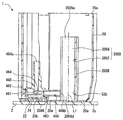
図1に示すように、本発明の第一実施形態による燃料供給装置1は、車両の燃料タンク2に搭載される。装置1は、燃料タンク2内の燃料を、内燃機関3の燃料噴射弁へ高圧ポンプ等を介して間接的に又は介さないで直接的に供給する。ここで、装置1の搭載される燃料タンク2は、樹脂又は金属により中空状に形成されることで、内燃機関3側へ供給する燃料を貯留する。また、装置1から燃料を供給する内燃機関3としては、ディーゼルエンジンであってもよいし、ガソリンエンジンであってもよい。尚、図1及び後述する図3〜6において上下方向及び横方向はそれぞれ、水平面上の車両における鉛直方向及び水平方向(以下、単に鉛直方向及び水平方向という)と実質一致している。
(First embodiment)
As shown in FIG. 1, a fuel supply device 1 according to a first embodiment of the present invention is mounted on a
(構成及び作動)
以下、装置1の構成及び作動を説明する。
(Configuration and operation)
Hereinafter, the configuration and operation of the apparatus 1 will be described.
図1〜4に示すように装置1は、フランジ10、サブタンク20、調整機構30、ポンプユニット40及び旋回壁構造50を備えている。
As shown in FIGS. 1 to 4, the apparatus 1 includes a
図1に示すようにフランジ10は、樹脂により円板状に形成され、燃料タンク2の天板部2aに装着されている。フランジ10は、天板部2aとの間にパッキン10aを挟み込むことにより、同板部2aに形成された貫通孔2bを閉塞している。図1,2に示すようにフランジ10は、燃料供給管12、リターン管14及び電気コネクタ16を一体に有している。
As shown in FIG. 1, the
燃料供給管12は、湾曲自在のフレキシブルチューブ12aを介して燃料タンク2内のポンプユニット40に連通している。それと共に燃料供給管12は、燃料タンク2外において内燃機関3との間の燃料経路4に連通している。こうした連通形態の燃料供給管12は、ポンプユニット40の燃料ポンプ42により燃料タンク2内から圧送される燃料を、同タンク2外の内燃機関3側へと供給する。リターン管14は、燃料タンク2外において燃料経路4からの分岐通路4aに連通している。それと共にリターン管14は、湾曲自在のフレキシブルチューブ14aを介して燃料タンク2内のポンプユニット40に連通している。こうした連通形態のリターン管14は、内燃機関3側への供給燃料から分流したリターン燃料を、燃料タンク2外から同タンク2内のポンプユニット40のうち残圧保持バルブ45へとリターンさせる。図2に示す電気コネクタ16は、燃料タンク2外の制御回路(図示しない)に燃料ポンプ42を電気接続する。
The
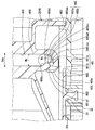
図1,3,4に示すようにサブタンク20は、樹脂により有底円筒状に形成され、燃料タンク2内に配置されている。サブタンク20の開口部20cは、上方に向けて開放されている。サブタンク20の底部20aは、燃料タンク2の底部2c上に載置されている。ここで図3,4に示すように、底部20aのうち最深底部20eから上方に向かって凹む凹底部20bには、流入口24が形成されている。流入口24は、凹底部20b及び底部2cの間に確保された流入空間22に連通している。それと共に流入口24は、ポンプユニット40のうちジェットポンプ46に連通している。こうした連通形態により燃料タンク2内の貯留燃料は、サブタンク20の下方に位置する流入空間22から、流入口24へと流入することで、ジェットポンプ46によりサブタンク20内まで汲み上げられる。尚、本実施形態の凹底部20b上には、後に詳述するジェットポンプ46からの負圧作用時に流入口24を開弁するように、図4に示すアンブレラバルブ27が設けられている。
As shown in FIGS. 1, 3, and 4, the
図1に示すように調整機構30は、一対の支柱32及び調整スプリング(図示しない)等から構成されている。各支柱32は、金属により円柱状に形成され、燃料タンク2内において上下方向に延伸している。各支柱32の上端は、フランジ10に固定されている。かかる上端よりも下方にて各支柱32は、サブタンク20により上下方向に摺動案内されている。調整スプリングは、サブタンク20内において対応する一支柱32の周囲に同軸上に配置され、それらサブタンク20及び対応支柱32との間に介装されている。こうした介装形態の調整スプリングは、図1,3,4に示すように、サブタンク20の底部20aを燃料タンク2の底部2cへと向かって押し付けている。
As shown in FIG. 1, the
ポンプユニット40は、サブタンク20内に収容されている。図2〜4に示すようにポンプユニット40は、サクションフィルタ41、燃料ポンプ42、ポンプホルダ43、リリーフバルブ44、残圧保持バルブ45及びジェットポンプ46等から構成されている。
The
サクションフィルタ41は、例えば不織布フィルタ等であり、底部20aのうち最深底部20eの上方においてサブタンク20内に配置されている。サクションフィルタ41は、サブタンク20内から燃料ポンプ42に吸入させる燃料を濾過することで、当該吸入燃料中の異物を除去する。
The
燃料ポンプ42は、サブタンク20内においてサクションフィルタ41の上方に接続されている。燃料ポンプ42は、本実施形態では電動式のポンプであり、湾曲自在のフレキシブル配線42aを介して電気コネクタ16に電気接続されている。燃料ポンプ42は、電気コネクタ16を通じて制御回路からの駆動制御を受けることで、作動する。かかる作動中の燃料ポンプ42は、サブタンク20内にてサクションフィルタ41を通じて吸入した燃料を、加圧する。
The
図1,3,4に示すようにポンプホルダ43は、樹脂によりアーム状に形成され、サブタンク20の開口部20cに装着されている。ポンプホルダ43は、燃料ポンプ42を外周側から保持している。
As shown in FIGS. 1, 3, and 4, the
図2〜4に示すようにリリーフバルブ44は、サブタンク20内において燃料ポンプ42の側方に接続されている。リリーフバルブ44は、燃料ポンプ42の吐出口(図示しない)に連通している。それと共にリリーフバルブ44は、フレキシブルチューブ12aを介して燃料供給管12に連通している。さらにリリーフバルブ44は、サブタンク20内にも連通している。こうした連通形態下、燃料ポンプ42から吐出されて内燃機関3側へと供給された燃料の圧力がリリーフ圧未満となる間は、リリーフバルブ44が閉弁して当該供給燃料の圧力を確保する。一方、内燃機関3側へ供給された燃料の圧力がリリーフ圧以上となると、リリーフバルブ44が開弁して当該供給燃料の圧力をサブタンク20内へと逃がす。
As shown in FIGS. 2 to 4, the
残圧保持バルブ45は、サブタンク20内において燃料ポンプ42の側方に接続されている。残圧保持バルブ45は、フレキシブルチューブ14aを介してリターン管14に連通している。それと共に残圧保持バルブ45は、ジェットポンプ46に連通している。こうした連通形態下、内燃機関3側へと供給された燃料の圧力が開弁圧以上となる間は、残圧保持バルブ45が開弁して当該供給燃料の一部を排出口450からジェットポンプ46側へと排出させる。一方、内燃機関3側へと供給された燃料の圧力が閉弁圧未満となると、残圧保持バルブ45が閉弁して当該供給燃料の圧力を保持する。
The residual
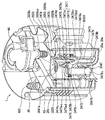
ジェットポンプ46は、樹脂により中空状に形成され、サブタンク20内において残圧保持バルブ45の側方に接続されている。図3,4に示すようにジェットポンプ46は、サブタンク20の底部20aのうち凹底部20b上に載置されている。ジェットポンプ46は、加圧部460、ノズル部461、吸入部462及びディフューザ部463を一体成形してなる。
The
加圧部460は、上下方向へストレートに延伸する円筒孔状に、加圧通路464を形成している。即ち加圧部460は、加圧通路464を形成する樹脂部分である。加圧通路464の上流端464uは、残圧保持バルブ45の排出口450に連通している。こうした連通形態の加圧通路464は、排出口450からの排出により上流端464uへと供給される加圧燃料を、図5,6に示す下方の下流端464d側へ向かって案内する。
The pressurizing
ノズル部461は、ノズル通路465の上流部分として連通通路部465aを形成する連通形成部461aと、同通路465の下流部分として絞り通路部465bを形成する絞り形成部461bとを、加圧部460の下方に有している。即ち、ノズル通路465を形成する樹脂部分としてのノズル部461は、連通通路部465aを形成する樹脂部分としての連通形成部461aと、絞り通路部465bを形成する樹脂部分としての絞り形成部461bとを、組み合わせて構成されている。
The
連通形成部461aは、連通通路部465aを実質1/8の部分球形空間状に形成している。連通通路部465aの上流端465auは、加圧通路464の下流端464dに連通している。ここで、図6〜8における横方向は、連通通路部465aの通路幅Wc及び加圧通路464の通路幅Wpを規定する共通幅方向Dcpとして、定義されている。かかる定義の下、連通通路部465aの通路幅Wcは、加圧通路464の通路幅Wpよりも小さい範囲に設定されている。また、こうした設定を実現するために図5〜7に示すように、加圧部460のうち加圧通路464の下流端464dを形成する部分には、同通路部465a側へ向かうほど縮径する円錐面状のテーパ通路壁面460aが、連通通路部465aとの連通箇所を除いて設けられている。
The
図5〜8に示すように連通形成部461aのうち、共通幅方向Dcpにおいて連通通路部465aを挟む両側にはそれぞれ、第一通路壁面461afと第二通路壁面461asとが設けられている。第一通路壁面461afは、共通幅方向Dcpに対して実質垂直な横方向及び上下方向に沿って広がる平面状に、形成されている。第一通路壁面461afのうち、連通通路部465aの下流端465adを形成する部分には、絞り通路部465bの上流端465buが開口している。本実施形態において絞り通路部465bの上流端465buは、第一通路壁面461afよりも第二通路壁面461as側にはみ出した一部分を除き、第一通路壁面461afよりも第二通路壁面461asから離間した箇所に設けられている。
As shown in FIGS. 5 to 8, a first passage wall surface 461af and a second passage wall surface 461as are provided on both sides of the
このような第一通路壁面461afに対して第二通路壁面461asは、絞り通路部465b側へ向かって、実質1/8の部分球形凹面状に湾曲している。ここで、特に本実施形態の第二通路壁面461asは、加圧通路464の下流端464dから下流側に離間した箇所から絞り通路部465bへと到るまで、連続して湾曲している。それと共に、本実施形態の第二通路壁面461asは、絞り通路部465bの上流端465buを連通通路部465a側から視る図6の断面視において、加圧通路464側から反時計方向に湾曲している。こうした湾曲形態により壁面461af,461as間の連通通路部465aでは、加圧通路464の通路幅Wpよりも小さな範囲にて、絞り通路部465b側へ向かうほど通路幅Wcが漸次縮小している。また、かかる連通通路部465aでは、図9(a)に矢印で示すように、加圧通路464から加圧燃料が流入することで発生する燃料流Ffは、湾曲形態の第二通路壁面461asに沿うことで旋回しながら、下流側の絞り通路部465bへと流入することになる。
With respect to the first passage wall surface 461af, the second passage wall surface 461as is curved in a substantially 1/8 partial spherical concave shape toward the
図5〜8に示すように、連通形成部461aの側方に一体成形される絞り形成部461bは、共通幅方向Dcpに対して実質垂直な横方向へとストレートに延伸する円筒孔状に、絞り通路部465bを形成している。絞り通路部465bの上流端465buは、上述の如く第一通路壁面461afに開口することで、連通通路部465aの下流端465adに連通している。絞り通路部465bにおいて燃料の流通流量は、連通通路部465aにおけるよりも絞られている。こうした絞り形態の絞り通路部465bには、図9(a)に矢印で示すように、燃料流Ffが第二通路壁面461asに沿って旋回しながら、連通通路部465aから流入してくる。その結果、絞り通路部465bの下流端465bdからは、図9(b)に示すように螺旋旋回した状態で、流量の絞られた燃料流Ffが流出することになる。
As shown in FIGS. 5 to 8, the
図5,6に示すように吸入部462は、凹底部20bを貫通した流入口24を上方から覆う扁平形空間状に、吸入通路468を形成している。即ち吸入部462は、吸入通路468を形成する樹脂部分である。吸入通路468は、加圧部460及びノズル部461の下方において流入口24に連通している。こうした連通形態の吸入通路468には、燃料タンク2内の貯留燃料が流入空間22及び開弁状態の流入口24を通じて流入可能となっている。
As shown in FIGS. 5 and 6, the
ディフューザ部463は、絞り通路部465bから側方のうち横方向へ同軸上に延伸する円筒孔状に、ディフューザ通路469を形成している。即ちディフューザ部463は、ディフューザ通路469を形成する樹脂部分である。ディフューザ通路469の上流端は、加圧部460の下方において絞り通路部465bの下流端465bdに連通する合流通路部469aを、吸入通路468と共同して構成している。一方でディフューザ通路469の下流端は、図3に示すように、側方のうち横方向を真っ直ぐ向いてサブタンク20内に連通する流出口469bを、構成している。こうした構成により、流量の絞られた加圧燃料が絞り通路部465bの下流端465bdから合流通路部469aへと噴出されて、当該噴出流の周囲に負圧が発生することで、開弁した流入口24から吸入通路468への流入燃料がディフューザ通路469へと吸入される。その結果、かかる吸入燃料は、ディフューザ通路469でのディフューザ作用を受けて圧送されることで、同通路469の流出口469bを通じてサブタンク20内に汲み上げられる。
The
このとき下流端465bdから、図9(b),(c)に示す如き螺旋旋回状態にて燃料が合流通路部469aへ噴出されることで通路469に発生する燃料流Ffは、通路断面全体に液膜を形成しながら、流出口469bからサブタンク20内へと流出する。ここで本実施形態では、絞り通路部465bから側方のうち横方向へと延伸する横軸線Lcが、想定される。かかる想定下、第二通路壁面461asが加圧通路464から反時計方向に湾曲することで、絞り通路部465bから視て横軸線Lcまわりの反時計方向へと螺旋旋回するように、燃料流Ffがディフューザ通路469にて発生するのである。
At this time, the fuel flow Ff generated in the
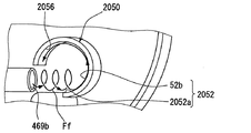
図3,10,11に示すように旋回壁構造50は、サブタンク20内において下方から上方へ向かって設けられている。具体的に旋回壁構造50は、曲壁面52、案内壁面54及びUターン壁面56を有している。
As shown in FIGS. 3, 10, and 11, the
曲壁面52は、サブタンク20と一体成形された板状の縦壁部28のうち特定板面28aの一部分により、構成されている。曲壁面52は、サブタンク20の底部20aのうち水平方向に広がる最深底部20eに対して実質垂直に設けられることで、上下方向と実質一致した鉛直方向に沿って延伸している。それと共に曲壁面52は、側方において対向する流出口469bよりも上方と、同口469bよりも下方とに跨って設けられている。
The
図3,10に示すように旋回壁構造50では、サブタンク20の下方から上方へ延伸する縦軸線Ll、特に鉛直方向に沿って延伸する縦軸線Llが、想定される。曲壁面52は、かかる想定の縦軸線Llまわりに実質1/4周の円筒形凹面状(所謂、円弧面状)に、湾曲している。ここで、本実施形態の曲壁面52は、上方視において流出口469bに近接する側に位置した近接端52aから、時計方向に湾曲している。
As shown in FIGS. 3 and 10, in the revolving
さらに旋回壁構造50では、図12にクロスハッチングを付して示すように、流出口469bを横軸線Lcに沿って側方に投影した投影領域Apが、想定される。かかる想定下、曲壁面52のうち上方視における流出口469bとの近接端52aは、投影領域Apから外れて配置されている。また一方、曲壁面52のうち投影領域Ap内に配置されている部分は、上方視において近接端52aよりも流出口469bから離間して湾曲する離間湾曲部52b(図3,10,11も参照)を、構成している。
Furthermore, in the revolving
こうした構成により、図13に矢印で示すように流出口469bから流出した燃料流Ffは、曲壁面52のうち離間湾曲部52bに衝突することで、同壁面52に沿って曲げられる。このとき本実施形態の燃料流Ffは、上方視において時計方向へと曲げられることになる。
With such a configuration, as indicated by an arrow in FIG. 13, the fuel flow Ff flowing out from the
図3,10,11に示すように案内壁面54は、縦壁部28のうち曲壁面52と同じ特定板面28aの一部分により、構成されている。案内壁面54は、曲壁面52と同様、底部20aのうち最深底部20eに対して実質垂直に設けられることで鉛直方向に沿って延伸していると共に、流出口469bよりも上方と下方とに跨って設けられている。案内壁面54は、曲壁面52のうち上方視における流出口469bとの近接端52aから、同口469b側へ向かって平面状に連続している。
As shown in FIGS. 3, 10, and 11, the
ここで、図10に示すように本実施形態の案内壁面54は、近接端52aにおける円弧状曲壁面52の接平面St上に設けられることで、縦軸線Llに実質垂直な横軸線Lcに沿って延伸している。こうした延伸形態により案内壁面54は、図13に矢印で示すように流出口469bから流出した燃料流Ffを、曲壁面52まで案内する。その結果として案内された燃料流Ffは、案内壁面54から連続して湾曲する曲壁面52の離間湾曲部52bに衝突できるので、上述の如き曲げ作用を受けることになる。
Here, as shown in FIG. 10, the
Uターン壁面56は、縦壁部28のうち曲壁面52及び案内壁面54と同じ特定板面28aの一部分と、サブタンク20において板状に成形されたタンク外壁部20dのうち内周面20diの一部分とにより、構成されている。Uターン壁面56は、曲壁面52及び案内壁面54と同様、底部20aのうち最深底部20eに対して実質垂直に設けられることで鉛直方向に沿って延伸していると共に、流出口469bよりも上方と下方とに跨って設けられている。Uターン壁面56は、曲壁面52のうち近接端52aとは反対側端52cから、上方視において略U字をもって連続している。
The
ここで、本実施形態のUターン壁面56のうち、縦壁部28に形成されて曲壁面52と滑らかに連続する部分は、同壁面52よりも小さな曲率で流出口469b側へと僅かに湾曲する円筒形凹面状の第一連続湾曲部56aを、構成している。また、Uターン壁面56のうち、タンク外壁部20dに形成されて第一連続湾曲部56aから流出口469b側に屈曲した部分は、同部56aよりも大きな曲率で流出口469b側へと湾曲する円筒形凹面状の第二連続湾曲部56bを、構成している。さらに、Uターン壁面56のうち、タンク外壁部20dに形成されて第二連続湾曲部56bから案内壁面54側に屈曲した部分は、上方視において二段の階段状に折り返される折返部56cを、構成している。これらの構成下、図13に矢印で示すように、曲壁面52により曲げられた燃料流Ffは、Uターン壁面56に沿ってUターンさせられることで、本実施形態では上方視にて時計方向へと旋回することになる。
Here, in the
(作用効果)
第一実施形態の旋回壁構造50によると、ノズル通路465からの燃料噴出により燃料タンク2内から貯留燃料を汲み上げるディフューザ通路469のうち、側方を向く流出口469bからサブタンク20内へと流出した燃料流Ffは、旋回させられる。具体的には、流出口469bからの燃料流Ffは、サブタンク20の下方から上方へと延伸する縦軸線Llまわりに湾曲した曲壁面52に沿って曲げられた後、同壁面52から連続したUターン壁面56に沿ってUターンすることで、旋回させられる。これにより、燃料中に含まれる比重の小さな気泡は、旋回流の中心部に集まることで、作用する浮力が増大するように気泡群を形成する。その結果として気泡群は、サブタンク20内にて下方から上方へと向かって設けられる旋回壁構造50によっては当該上方への移動を阻害され難い。また、それと合わせて有底筒状のサブタンク20では、ジェットポンプ46及び燃料ポンプ42を収容可能にする開口部20cが上方へ向けて開放されるので、当該上方への移動により気泡群が排出され易くなる。しかも燃料ポンプ42は、こうした旋回壁構造50により気泡の除去されたサブタンク20内の燃料を逃さずに吸入して内燃機関3側へと吐出し得るので、燃料の供給ロスを抑制できる。
(Function and effect)
According to the
以上の如き第一実施形態によれば、燃料供給ロスの抑制により省エネルギー性を達成するのと両立させて、気泡の除去による内燃機関3の性能確保を達成することも、可能となる。
According to the first embodiment as described above, it is possible to achieve ensuring of the performance of the
また、流出口469bよりも下方と上方とに跨って設けられる旋回壁構造50の曲壁面52及びUターン壁面56によると、同口469bからの燃料流Ffを逃さないようにして、確実に曲げてからUターンさせ得る。これによれば、燃料流Ffへの旋回流の付与効率、ひいては気泡の除去効率を高めることができるので、内燃機関3の性能確保の信頼性を向上させることが可能となる。
In addition, according to the
さらに、サブタンク20の底部20aから上方へ鉛直方向に沿って延伸する旋回壁構造50の曲壁面52及びUターン壁面56によると、燃料流Ffに与える旋回流の中心軸線方向を、当該鉛直方向へと向けさせ得る。これによれば、旋回流の中心部に集まった気泡群を、浮力の作用する鉛直方向に円滑に移動させることができるので、気泡の除去効率を高めて、内燃機関3の性能確保の信頼性を向上させることが可能となる。
Furthermore, according to the
またさらに、流出口469bを側方に投影した投影領域Apには、燃料と共に気泡も流入する。故に、気泡を含んだ燃料流Ffは、曲壁面52のうち上方視にて投影領域Apから外れた近接端52aよりも、流出口469bから下流側に離間した離間湾曲部52bへと優先的に衝突し得るので、同部52の湾曲形態に沿って確実に曲がることとなる。これによれば、気泡を含んだ燃料流Ffが曲壁面52へと向かわずに、当該気泡が燃料中に残存する事態を抑制できるので、内燃機関3の性能確保の信頼性を向上させることが可能となる。
Furthermore, bubbles also flow into the projection area Ap where the
加えて、流出口469bからの燃料流は、縦軸線Llまわりでは実質1/4周の円筒形凹面状に湾曲した曲壁面52に沿って曲げられることで、同線Llまわりに確実に旋回し得る。それと共に、流出口469bからの燃料流Ffは、Uターン壁面56のうち曲壁面52から連続して流出口469b側に湾曲する連続湾曲部56a,56bに沿うことで、縦軸線Llまわりの旋回流を妨げ難くなる。これらによれば、燃料流Ffへの旋回流の付与効率、ひいては気泡の除去効率を高めることができるので、内燃機関3の性能確保の信頼性を向上させることが可能となる。
In addition, the fuel flow from the
また加えて、流出口469bからの燃料流Ffは、案内壁面54により案内されることで、同壁面54から連続した曲壁面52の縦軸線Llまわりの湾曲形態に沿って確実に曲げられ得る。これによれば、燃料流Ffへの旋回流の付与効率、ひいては気泡の除去効率を高めることができるので、内燃機関3の性能確保の信頼性を向上させることが可能となる。
In addition, the fuel flow Ff from the
さらに加えて、ディフューザ通路469では、ノズル通路465から側方へと延伸する横軸線Lcまわりに、同通路465から噴出の燃料流Ffが螺旋旋回することになる。このとき、ノズル通路465から視て反時計方向に螺旋旋回した状態でディフューザ通路469の流出口469bから流出する燃料流Ffは、上方視にて流出口469bとの近接端52aから時計方向へと湾曲した曲壁面52に衝突することで、上方へ向かって当該時計方向に螺旋旋回する。これによれば、螺旋旋回の作用と浮力の作用とが相俟って、旋回流の中心部から上方へと向かう気泡群の移動速度が増大し得る。故に、気泡の除去効率を高めて、内燃機関3の性能確保の信頼性を向上させることが可能となる。
In addition, in the
(第二実施形態)
図14〜17に示すように本発明の第二実施形態は、第一実施形態の変形例である。第二実施形態のジェットポンプ2046では、絞り通路部465bの上流端465buを連通通路部465a側から視る図15,16の断面視において、加圧通路464側から時計方向へ湾曲するように、第二通路壁面2461asが設けられている。また、この点以外について第二通路壁面2461asは、第一実施形態の第二通路壁面461asに準じた構成を備えている。こうした構成から、図18(a)に矢印で示すように燃料流Ffは、第二通路壁面2461asに沿って旋回しながら、絞り通路部465bへと流入することになる。その結果、図18(b),(c)に矢印で示すように燃料流Ffは、絞り通路部465bから視て横軸線Lcまわりの時計方向へと螺旋旋回するように、ディフューザ通路469にて発生することになる。
(Second embodiment)
As shown in FIGS. 14-17, 2nd embodiment of this invention is a modification of 1st embodiment. In the
図14,17に示すように第二実施形態の旋回壁構造2050では、サブタンク20と一体成形された部分円筒状の縦壁部2028のうち内周面2028aの一部により、曲壁面2052が構成されている。縦軸線Llまわりに実質1/4周の円筒形凹面状を呈する曲壁面2052は、上方視において流出口469bに近接する側の近接端2052aから反時計方向へと湾曲している。また、これらの点以外について曲壁面2052は、第一実施形態の曲壁面52に準じた構成を備えている。こうした構成から、図19に矢印で示すように燃料流Ffは、離間湾曲部52bに衝突してから曲壁面2052に沿って流動することで、上方視において反時計方向へと曲げられることになる。
As shown in FIGS. 14 and 17, in the revolving
図14,17に示すように第二実施形態の旋回壁構造2050では、第一実施形態の如き案内壁面54は設けられていない。それと共に旋回壁構造2050では、縦壁部2028のうち曲壁面2052と同じ内周面2028aの一部分により、Uターン壁面2056が構成されている。縦軸線Llまわりに実質1/2周の円筒形凹面状を呈するUターン壁面2056は、曲壁面2052のうち近接端2052aとは反対側端2052cから、上方視において略U字状に連続している。こうしたUターン壁面2056は、曲壁面2052から滑らかに連続する周方向全域にて、同壁面2052と実質同一曲率をもって流出口469b側へと湾曲する連続湾曲部2056dを、構成している。また、これらの点以外についてUターン壁面2056は、第一実施形態のUターン壁面56に準じた構成を備えている。こうした構成から、図19に矢印で示すように曲壁面2052により曲げられた燃料流Ffは、Uターン壁面2056に沿ってUターンさせられることで、本実施形態では上方視にて反時計方向へと旋回する旋回流となる。
As shown in FIGS. 14 and 17, in the revolving
ここまで説明した第二実施形態においても、ディフューザ通路469では、ノズル通路465から側方へと延伸する横軸線Lcまわりに、同通路465から噴出の燃料流Ffが螺旋旋回することになる。このとき、ノズル通路465から視て時計方向への螺旋旋回状態でディフューザ通路469の流出口469bから流出する燃料流Ffは、上方視にて流出口469bとの近接端2052aから反時計方向へと湾曲した曲壁面2052に衝突することで、上方へ向かって当該反時計方向に螺旋旋回する。これによれば、螺旋旋回の作用と浮力の作用とが相俟って、旋回流の中心部から上方へと向かう気泡群の移動速度が増大し得る。故に、気泡の除去効率を高めて、内燃機関3の性能確保の信頼性を向上させることが可能となるのである。また、これ以外の作用効果については、案内壁面54に関する作用効果を除いて、第一実施形態と同様に発揮可能である。
Also in the second embodiment described so far, in the
(第三実施形態)
図20〜22に示すように本発明の第三実施形態は、第一実施形態の変形例である。図20に示すように第三実施形態のサブタンク3020には、樹脂により一体成形又は別体成形された流入管3029が、設けられている。流入管3029は、燃料タンク2内のうちサブタンク3020の下方から外れた側方箇所に、連通している。それと共に流入管3029は、燃料タンク2内のうちサブタンク3020内にてジェットポンプ46とは別に設けられたジェットポンプ3047に、連通している。尚、第三実施形態では、一方のジェットポンプ46が第一ジェットポンプ46と定義され、他方のジェットポンプ3047が第二ジェットポンプ3047と定義されている。
(Third embodiment)
As shown in FIGS. 20-22, 3rd embodiment of this invention is a modification of 1st embodiment. As shown in FIG. 20, the
図20〜22に示すように第二ジェットポンプ3047は、サブタンク3020内のうちポンプ室3020fに、収容されている。ここでポンプ室3020fは、サブタンク3020と一体成形された板状の縦壁部3028により、第一ジェットポンプ46からは仕切られている。かかる仕切り形態のポンプ室3020fには、旋回壁構造3050の各壁面52,54,3056が露出しないように形成されている。尚、サブタンク3020について、以上説明した点以外は、第一実施形態のサブタンク20に準じた構成となっている。
As shown in FIGS. 20 to 22, the
樹脂により中空状に形成される第二ジェットポンプ3047は、加圧部3470、ノズル部3471、吸入部3472及びディフューザ部3473を有している。加圧部3470を成形してなる成形品3047aに対して、ノズル部3471、吸入部3472及びディフューザ部3473を一体成形してなる成形品3047bが組み付けられることで、第二ジェットポンプ3047は構成されている。
The
加圧部3470は、L字状に延伸する円筒孔状に、加圧通路3474を形成している。加圧通路3474の上流端3474uは、第一ジェットポンプ46の加圧通路464と共に、残圧保持バルブ45の排出口450に連通している。
The
図21,22に示すようにノズル部3471は、ノズル通路3475の上流部分として連通通路部3475aを形成する連通形成部3471aと、同通路3475の下流部分として絞り通路部3475bを形成する絞り形成部3471bとを、加圧部3470の下方に有している。連通形成部3471aは、連通通路部3475aを段付円筒孔状に形成している。連通通路部3475aの上流端3475auは、加圧通路3474の下流端3474dに連通している。絞り通路部3475bは、下方に向かうほど縮径する円錐孔状(テーパ孔状)に、絞り通路部3475bを形成している。絞り通路部3475bにおいて燃料の流通流量は、連通通路部3475aにおけるよりも絞られている。絞り通路部3475bの上流端3475buは、連通通路部3475aの下流端3475adに連通している。
As shown in FIGS. 21 and 22, the
吸入部3472は、逆L字状に延伸する円筒孔状に、吸入通路3478を形成している。吸入通路3478の上流端3478uは、加圧部3470の下方において流入管3029(図20参照)に連通している。
The
ディフューザ部3473は、絞り通路部3475bと同軸上に設けられて鉛直方向に延伸する円筒孔状に、ディフューザ通路3479を形成している。ディフューザ通路3479の上流端は、加圧部3470の下方において絞り通路部3475bの下流端3475bdに連通する合流通路部3479aを、吸入通路3478と共同して構成している。一方でディフューザ通路3479の下流端は、下方を向いてポンプ室3020fに連通する流出口3479bを、構成している。
The
以上の如き第二ジェットポンプ3047の構成により、排出口450から加圧通路3474により案内されて連通通路部3475aに流入することになる加圧燃料は、絞り通路部3475bにより流通流量を絞られて合流通路部3479aへと噴出される。その結果、噴出流の周囲に負圧が発生することで、燃料タンク2内の貯留燃料は、サブタンク3020の側方箇所から流入管3029を通じて、吸入通路3478及びディフューザ通路3479へと順次吸入される。さらに、吸入された燃料は、ディフューザ通路3479によりディフューザ作用を受けて圧送されることで、同通路3479の流出口3479bを通じてポンプ室3020fに汲み上げられる。
With the configuration of the
さて、図20に示すように第三実施形態の旋回壁構造3050は、第一実施形態と実質同一構成の曲壁面52及び案内壁面54と、第一実施形態とは異なる構成のUターン壁面3056とを、有している。上方視において略U字形のUターン壁面3056のうち、タンク外壁部3020dに形成された連続平面部3056eは、曲壁面52のうち近接端52aとは反対側端52cから連続している。連続平面部3056eは、曲壁面52に対して流出口469b側へ屈曲する平面状に、形成されている。また、Uターン壁面3056のうち、ポンプ室3020fを仕切る縦壁部3028に形成された折返部3056cは、連続平面部3056eから案内壁面54側へと折り返されている。折返部3056cは、曲壁面52よりも小さな曲率で湾曲する円筒形凹面状に、形成されている。さらに、これらの点以外についてUターン壁面3056は、第一実施形態のUターン壁面56に準じた構成を備えている。
Now, as shown in FIG. 20, the turning
図20〜22に示すように、縦壁部3028において折返部3056cを形成する部分3028bでは、底部20aのうち最深底部20eからの鉛直方向高さが、他の部分3028cよりも低く設定されている。かかる設定により折返部3056cの上端には、ポンプ室3020fの内外を連通するように、合流口3056coが開口している。
As shown in FIGS. 20-22, in the
以上の如き旋回壁構造3050の構成下、図23に矢印で示すように、第一ジェットポンプ46の流出口469bから案内壁面54により案内されて曲壁面52により曲げられた燃料流Ffは、Uターン壁面3056に沿ってUターンさせられる。その結果、第三実施形態においても燃料流Ffは、上方視にて時計方向へと旋回することになる。また一方、第二ジェットポンプ3047によりポンプ室3020fまで汲み上げられて、合流口3056coから同室3020f外へと向かうことになる燃料流Fjは、流出口469bからの燃料流Ffに合流する。このとき第二ジェットポンプ3047からの燃料流Fjは、第一実施形態と同様の原理により上方へ向かって螺旋旋回する燃料流Ffへと合流することで、当該燃料流Ffと同様な旋回流となる。
Under the configuration of the swirling
故に、ここまで説明した第三実施形態では、第一ジェットポンプ46によりサブタンク3020の下方から汲み上げられた燃料中の気泡だけでなく、第二ジェットポンプ3047により当該下方以外の箇所から汲み上げられた燃料中の気泡も除去できる。これによれば、気泡の除去作用並びに燃料供給ロスの抑制作用を発揮する旋回壁構造を、第一ジェットポンプ46及び第二ジェットポンプ3047に共通化して構成の簡素化を図りつつ、省エネルギー性と内燃機関3の性能確保とを両立させることが可能となる。また、これ以外の作用効果については、第一実施形態と同様に発揮可能である。
Therefore, in the third embodiment described so far, not only the bubbles in the fuel pumped from the lower side of the sub-tank 3020 by the
(他の実施形態)
以上、本発明の複数の実施形態について説明したが、本発明は、それらの実施形態に限定して解釈されるものではなく、本発明の要旨を逸脱しない範囲内において種々の実施形態及び組み合わせに適用することができる。
(Other embodiments)
Although a plurality of embodiments of the present invention have been described above, the present invention is not construed as being limited to these embodiments, and various embodiments and combinations can be made without departing from the scope of the present invention. Can be applied.
具体的に、第一〜第三実施形態に関する変形例1では、旋回壁構造50,2050,3050の各壁面52,2052,54,56,2056,3056のうち少なくとも一壁面を、流出口469bとの対向箇所から下方へと延伸させて、当該対向箇所よりも上方には配置しなくてもよい。また、第一〜第三実施形態に関する変形例2では、旋回壁構造50,2050,3050の各壁面52,2052,54,56,2056,3056のうち少なくとも一壁面を、流出口469bとの対向箇所から上方へと延伸させて、当該対向箇所よりも下方には配置しなくてもよい。尚、かかる変形例2の対象となる壁面については、サブタンク20,3020の底部20aから上方へ向かって延伸形成してもよいし、同底部20aとは離間した箇所から上方へ向かって延伸形成してもよい。
Specifically, in Modification 1 regarding the first to third embodiments, at least one of the wall surfaces 52, 2052, 54, 56, 2056, and 3056 of the revolving
第一〜第三実施形態に関する変形例3では、旋回壁構造50,2050,3050の各壁面52,2052,54,56,2056,3056のうち少なくとも一壁面を、鉛直方向に対して傾けてもよい。また、第一〜第三実施形態に関する変形例4では、サブタンク20,3020の下方から上方へ延伸する限りにおいて、鉛直方向とは傾いた縦軸線Llを、旋回壁構造50,2050,3050の曲壁面52,2052に関して想定してもよい。さらにまた、第一〜第三実施形態に関する変形例5では、旋回壁構造50,2050,3050の曲壁面52,2052の近接端52a,2052aを、投影領域Apに配置してもよい。
In the third modified example related to the first to third embodiments, even if at least one of the wall surfaces 52, 2052, 54, 56, 2056, 3056 of the revolving
第一〜第三実施形態に関する変形例6では、旋回壁構造50,2050,3050の曲壁面52,2052を、縦軸線Llまわりに1/4周を超える円筒形凹面状に、湾曲させてもよい。また、第一〜第三実施形態に関する変形例7では、旋回壁構造50,2050,3050の曲壁面52,2052を、縦軸線Llまわりに1/4周未満の円筒形凹面状に形成してもよい。さらにまた、第一〜第三実施形態に関する変形例8では、円筒形凹面状以外の凹面状に湾曲させてもよい。
In the sixth modified example related to the first to third embodiments, the curved wall surfaces 52 and 2052 of the
第一及び第二実施形態に関する変形例9では、旋回壁構造50,2050のUターン壁面56,2056に連続湾曲部56a,56b,2056dを設けないで、例えば第三実施形態に準じた連続平面部3056e等を設けてもよい。また、第一及び第三実施形態に関する変形例10では、案内壁面54を設けなくてもよい。
In the modification 9 regarding the first and second embodiments, the continuous
第二実施形態に関する変形例11では、図24に示すように、サブタンク20とは別体に成形されて後固定された縦壁部2028により、旋回壁構造2050の各壁面2052,2056を形成してもよい。また、第三実施形態に関する変形例12では、旋回壁構造3050に代えて、第一又は第二実施形態に準ずる構成の旋回壁構造50,2050を採用してもよい。
In the eleventh modification related to the second embodiment, as shown in FIG. 24, the wall surfaces 2052 and 2056 of the
第一及び第三実施形態に関する変形例13のジェットポンプ46では、絞り通路部465bの上流端465buを連通通路部465a側から視る断面視において、加圧通路464側から時計方向へと湾曲するように、第二通路壁面461asを設けてもよい。この場合の旋回壁構造50,3050では、流出口469bとの近接端52aから上方視にて反時計方向へと湾曲するように、曲壁面52を設けるとよい。
In the
第二実施形態に関する変形例14のジェットポンプ2046では、絞り通路部465bの上流端465buを連通通路部465a側から視る断面視において、加圧通路464側から反時計方向へと湾曲するように、第二通路壁面2461asを設けてもよい。この場合の旋回壁構造2050では、流出口469bとの近接端2052aから上方視にて時計方向へと湾曲するように、曲壁面2052を設けるとよい。
In the
第一〜第三実施形態に関する変形例15では、第二通路壁面461as,2461asを湾曲させずに、例えば平面状等に形成することで、横軸線Lcに沿う燃料流Ffをディフューザ通路469に発生させてもよい。また、第一〜第三実施形態に関する変形例16では、ジェットポンプ46,2046の一部を別体成形して残部に後固定させてもよい。
In the modified example 15 related to the first to third embodiments, the fuel flow Ff along the horizontal axis Lc is generated in the
1 燃料供給装置、2 燃料タンク、3 内燃機関、20,3020 サブタンク、20a 底部、20e 最深底部、20c 開口部、42 燃料ポンプ、46,2046 ジェットポンプ・第一ジェットポンプ、50,2050,3050 旋回壁構造、52,2052 曲壁面、52a,2052a 近接端、52b 離間湾曲部、54 案内壁面、56,2056,3056 Uターン壁面、56a 第一連続湾曲部、56b 第二連続湾曲部、465 ノズル通路、469 ディフューザ通路、469b 流出口、2056d 連続湾曲部、3020f ポンプ室、3047 ジェットポンプ・第二ジェットポンプ、3056co 合流口、Ap 投影領域、Ff,Fj 燃料流、Lc 横軸線、Ll 縦軸線
DESCRIPTION OF SYMBOLS 1 Fuel supply apparatus, 2 Fuel tank, 3 Internal combustion engine, 20, 3020 Sub tank, 20a Bottom part, 20e Deepest bottom part, 20c Opening part, 42 Fuel pump, 46, 2046 Jet pump / first jet pump, 50, 2050, 3050 Rotation Wall structure, 52, 2052 Curved wall surface, 52a, 2052a Proximal end, 52b Separated curved portion, 54 Guide wall surface, 56, 2056, 3056 U-turn wall surface, 56a First continuous curved portion, 56b Second continuous curved portion, 465
Claims (9)
前記燃料タンク内に配置され、開口部(20c)が上方へ向けて開放される有底筒状のサブタンク(20,3020)と、
前記サブタンク内に収容され、ノズル通路(465)からディフューザ通路(469)へ加圧燃料を噴出させることにより、前記ディフューザ通路を通じて前記燃料タンク内の貯留燃料を前記サブタンク内へ汲み上げるジェットポンプ(46)と、
前記サブタンク内に収容され、前記ジェットポンプにより前記サブタンク内に汲み上げられた燃料を吸入して前記内燃機関側へ吐出する燃料ポンプ(42)と、
前記サブタンク内において下方から上方へ向かって設けられ、前記ディフューザ通路のうち側方を向く流出口(469b)から離間しており、前記流出口から前記サブタンク内へ流出した燃料流を旋回させる旋回壁構造(50,3050)とを、備え、
前記サブタンクの下方から上方へ延伸する縦軸線(Ll)が想定される前記旋回壁構造は、
前記縦軸線まわりに湾曲することにより、前記流出口からの燃料流を曲げる曲壁面(52)と、
前記曲壁面から連続することにより、前記曲壁面により曲げられた燃料流をUターンさせるUターン壁面(56,3056)とを、有し、
前記ノズル通路から側方へ延伸する横軸線(Lc)を想定したとき、前記ノズル通路からの燃料の噴出により、前記ノズル通路から視て当該横軸線まわりの反時計方向に螺旋旋回する燃料流(Ff)が前記ディフューザ通路に発生し、
前記曲壁面は、上方視において前記流出口に近接する側の近接端(52a)から時計方向に湾曲することを特徴とする燃料供給装置。 A fuel supply device (1) for supplying fuel in a fuel tank (2) to an internal combustion engine (3) side outside the fuel tank,
A bottomed cylindrical sub-tank (20, 3020) disposed in the fuel tank and having an opening (20c) opened upward;
A jet pump (46) accommodated in the sub-tank and pumps the fuel stored in the fuel tank into the sub-tank through the diffuser passage by ejecting pressurized fuel from the nozzle passage (465) to the diffuser passage (469). When,
A fuel pump (42) accommodated in the sub-tank and sucking the fuel pumped into the sub-tank by the jet pump and discharging it to the internal combustion engine side;
A swivel wall that is provided in the sub-tank from the bottom to the top and is spaced apart from a lateral outlet (469b) in the diffuser passage, and that swirls the fuel flow that has flowed into the sub-tank from the outlet. A structure (50, 3050),
The swivel wall structure that is assumed to have a longitudinal axis (Ll) extending from the bottom to the top of the sub-tank,
A curved wall surface (52) for bending the fuel flow from the outlet by curving around the longitudinal axis;
A U-turn wall surface (56, 3056) for making a U-turn the fuel flow bent by the curved wall surface by being continuous from the curved wall surface;
Assuming a horizontal axis (Lc) extending laterally from the nozzle passage, a fuel flow spirally swirling counterclockwise around the horizontal axis as viewed from the nozzle passage due to the ejection of fuel from the nozzle passage ( Ff) occurs in the diffuser passage,
The songs wall surface, fuel feeder side of proximal end proximate to the outlet in the upper view from (52a) you characterized in that curved clockwise.
前記燃料タンク内に配置され、開口部(20c)が上方へ向けて開放される有底筒状のサブタンク(20)と、
前記サブタンク内に収容され、ノズル通路(465)からディフューザ通路(469)へ加圧燃料を噴出させることにより、前記ディフューザ通路を通じて前記燃料タンク内の貯留燃料を前記サブタンク内へ汲み上げるジェットポンプ(2046)と、
前記サブタンク内に収容され、前記ジェットポンプにより前記サブタンク内に汲み上げられた燃料を吸入して前記内燃機関側へ吐出する燃料ポンプ(42)と、
前記サブタンク内において下方から上方へ向かって設けられ、前記ディフューザ通路のうち側方を向く流出口(469b)から離間しており、前記流出口から前記サブタンク内へ流出した燃料流を旋回させる旋回壁構造(2050)とを、備え、
前記サブタンクの下方から上方へ延伸する縦軸線(Ll)が想定される前記旋回壁構造は、
前記縦軸線まわりに湾曲することにより、前記流出口からの燃料流を曲げる曲壁面(2052)と、
前記曲壁面から連続することにより、前記曲壁面により曲げられた燃料流をUターンさせるUターン壁面(2056)とを、有し、
前記ノズル通路から側方へ延伸する横軸線(Lc)を想定したとき、前記ノズル通路からの燃料の噴出により、前記ノズル通路から視て当該横軸線まわりの時計方向に螺旋旋回する燃料流(Ff)が前記ディフューザ通路に発生し、
前記曲壁面は、上方視において前記流出口に近接する側の近接端(2052a)から反時計方向に湾曲することを特徴とする燃料供給装置。 A fuel supply device (1) for supplying fuel in a fuel tank (2) to an internal combustion engine (3) side outside the fuel tank,
A bottomed cylindrical sub tank (20) disposed in the fuel tank and having an opening (20c) opened upward;
A jet pump (2046) which is accommodated in the sub tank and pumps the fuel stored in the fuel tank into the sub tank through the diffuser passage by ejecting pressurized fuel from the nozzle passage (465) to the diffuser passage (469). When,
A fuel pump (42) accommodated in the sub-tank and sucking the fuel pumped into the sub-tank by the jet pump and discharging it to the internal combustion engine side;
A swivel wall that is provided in the sub-tank from the bottom to the top and is spaced apart from a lateral outlet (469b) in the diffuser passage, and that swirls the fuel flow that has flowed into the sub-tank from the outlet. A structure (2050),
The swivel wall structure that is assumed to have a longitudinal axis (Ll) extending from the bottom to the top of the sub-tank,
A curved wall surface (2052) that bends the fuel flow from the outlet by curving around the longitudinal axis;
A U-turn wall surface (2056) that U-turns the fuel flow bent by the curved wall surface by being continuous from the curved wall surface;
Assuming a horizontal axis (Lc) extending laterally from the nozzle passage, a fuel flow (Ff) spirally swirls clockwise around the horizontal axis as viewed from the nozzle passage due to the ejection of fuel from the nozzle passage. ) Occurs in the diffuser passage,
The songs wall surface, fuel feeder you wherein the curved proximal end of the side close to the outlet in the upper view from the (2052a) in a counterclockwise direction.
前記曲壁面は、前記案内壁面から連続して前記縦軸線まわりに湾曲することにより、前記流出口から案内された燃料流(Ff)を曲げることを特徴とする請求項1〜7のいずれか一項に記載の燃料供給装置。 The swirl wall structure (50, 3050) has a guide wall surface (54) for guiding the fuel flow (Ff) from the outlet to the curved wall surface,
The songs wall, by bending around the longitudinal axis continuously from the guide wall surfaces, any one of the claims 1-7, characterized in that bending the fuel flow is guided from the outlet (Ff) The fuel supply device according to item.
前記燃料タンク内の貯留燃料を前記サブタンクの下方以外の箇所から前記サブタンク内へ汲み上げる第二ジェットポンプ(3047)とを、備え、
前記旋回壁構造(3050)は、前記流出口からの燃料流(Ff)に前記第二ジェットポンプからの燃料流(Fj)を合流させる合流口(3056co)を、有することを特徴とする請求項1〜8のいずれか一項に記載の燃料供給装置。 As the jet pump, a first jet pump (46) for pumping the fuel stored in the fuel tank from below the sub tank (3020) into the sub tank;
A second jet pump (3047) for pumping the fuel stored in the fuel tank from a location other than below the sub tank into the sub tank,
The swirling wall structure (3050) has a junction (3056co) that joins the fuel flow (Fj) from the second jet pump to the fuel flow (Ff) from the outlet. The fuel supply device according to any one of 1 to 8 .
Priority Applications (3)
| Application Number | Priority Date | Filing Date | Title |
|---|---|---|---|
| JP2014209562A JP6476722B2 (en) | 2014-10-13 | 2014-10-13 | Fuel supply device |
| PCT/JP2015/005068 WO2016059769A1 (en) | 2014-10-13 | 2015-10-06 | Fuel supply device |
| US15/305,171 US9850865B2 (en) | 2014-10-13 | 2015-10-06 | Fuel supply device |
Applications Claiming Priority (1)
| Application Number | Priority Date | Filing Date | Title |
|---|---|---|---|
| JP2014209562A JP6476722B2 (en) | 2014-10-13 | 2014-10-13 | Fuel supply device |
Publications (3)
| Publication Number | Publication Date |
|---|---|
| JP2016079829A JP2016079829A (en) | 2016-05-16 |
| JP2016079829A5 JP2016079829A5 (en) | 2016-09-08 |
| JP6476722B2 true JP6476722B2 (en) | 2019-03-06 |
Family
ID=55746331
Family Applications (1)
| Application Number | Title | Priority Date | Filing Date |
|---|---|---|---|
| JP2014209562A Expired - Fee Related JP6476722B2 (en) | 2014-10-13 | 2014-10-13 | Fuel supply device |
Country Status (3)
| Country | Link |
|---|---|
| US (1) | US9850865B2 (en) |
| JP (1) | JP6476722B2 (en) |
| WO (1) | WO2016059769A1 (en) |
Families Citing this family (11)
| Publication number | Priority date | Publication date | Assignee | Title |
|---|---|---|---|---|
| JP6432217B2 (en) * | 2014-08-29 | 2018-12-05 | 株式会社デンソー | Fuel supply device |
| JP6287749B2 (en) * | 2014-10-13 | 2018-03-07 | 株式会社デンソー | Jet pump, manufacturing method thereof, and fuel supply device |
| JP6331980B2 (en) * | 2014-11-06 | 2018-05-30 | 株式会社デンソー | Fuel supply device |
| US10549631B2 (en) | 2016-03-30 | 2020-02-04 | Walbro Llc | Fuel pump assembly with removable and/or movable supports |
| US10259313B2 (en) * | 2016-03-30 | 2019-04-16 | Walbro Llc | Fuel pump assembly with removable supports |
| US10744869B2 (en) * | 2016-11-21 | 2020-08-18 | Daniel Ray Enyeart | Integrated fuel tank assembly |
| JP6992669B2 (en) * | 2018-04-27 | 2022-01-13 | 株式会社デンソー | Fuel supply device |
| US10934012B2 (en) | 2018-06-08 | 2021-03-02 | Textron Systems Corporation | Using a passive separator to separate air and fuel of a fuel mixture passively when delivering fuel to a combustion engine of an unmanned aerial vehicle |
| JP7103038B2 (en) | 2018-08-01 | 2022-07-20 | 株式会社デンソー | Fuel supply device |
| KR20220040066A (en) * | 2020-09-23 | 2022-03-30 | 현대자동차주식회사 | Fuel fill system of fuel pump reservoir |
| US11485221B2 (en) * | 2021-03-01 | 2022-11-01 | Hyster-Yale Group, Inc. | Fuel-supply assembly for internal combustion engine and method for assembling the same |
Family Cites Families (18)
| Publication number | Priority date | Publication date | Assignee | Title |
|---|---|---|---|---|
| JPH0560100A (en) | 1991-09-02 | 1993-03-09 | Nippondenso Co Ltd | Fuel supplying device |
| JP2961994B2 (en) | 1991-10-08 | 1999-10-12 | 株式会社デンソー | Fuel supply device |
| DE19750036C2 (en) * | 1997-11-12 | 1999-09-02 | Mannesmann Vdo Ag | Fuel delivery device |
| JP3820579B2 (en) * | 1997-12-02 | 2006-09-13 | 株式会社デンソー | Fuel supply device |
| FR2779184B1 (en) * | 1998-05-26 | 2001-01-26 | Marwal Systems | FUEL PUMP ASSEMBLY IN A MOTOR VEHICLE TANK |
| US6619271B2 (en) | 2001-01-24 | 2003-09-16 | Nifco Inc. | Fuel supply apparatus |
| JP3987728B2 (en) * | 2001-01-24 | 2007-10-10 | 株式会社ニフコ | Fuel supply device |
| JP4370610B2 (en) * | 2001-06-29 | 2009-11-25 | 株式会社デンソー | Fuel supply device |
| JP2003293875A (en) * | 2002-04-03 | 2003-10-15 | Aisan Ind Co Ltd | Reserve container unit |
| JP3929809B2 (en) * | 2002-04-03 | 2007-06-13 | 愛三工業株式会社 | Reserve container unit |
| JP2005076458A (en) * | 2003-08-29 | 2005-03-24 | Mitsuba Walbro Inc | Fuel supply system |
| JP4395893B2 (en) * | 2006-03-17 | 2010-01-13 | 株式会社デンソー | Jet pump, fuel supply device using the same, and jet pump welding method |
| US7757671B2 (en) * | 2006-09-29 | 2010-07-20 | Denso Corporation | Fuel feed apparatus |
| JP2009197675A (en) * | 2008-02-21 | 2009-09-03 | Denso Corp | Fuel injection device |
| US20110041931A1 (en) | 2009-08-21 | 2011-02-24 | Gmglobal Technology Operations, Inc. | Diesel Fuel Pump Module with Fuel Wax By-Pass |
| US9435304B2 (en) | 2012-08-27 | 2016-09-06 | Robert Bosch Gmbh | Diesel fuel pump module |
| JP6318987B2 (en) * | 2013-11-05 | 2018-05-09 | 株式会社デンソー | Fuel supply device |
| JP6287749B2 (en) | 2014-10-13 | 2018-03-07 | 株式会社デンソー | Jet pump, manufacturing method thereof, and fuel supply device |
-
2014
- 2014-10-13 JP JP2014209562A patent/JP6476722B2/en not_active Expired - Fee Related
-
2015
- 2015-10-06 US US15/305,171 patent/US9850865B2/en active Active
- 2015-10-06 WO PCT/JP2015/005068 patent/WO2016059769A1/en active Application Filing
Also Published As
| Publication number | Publication date |
|---|---|
| WO2016059769A1 (en) | 2016-04-21 |
| US20170260943A1 (en) | 2017-09-14 |
| US9850865B2 (en) | 2017-12-26 |
| JP2016079829A (en) | 2016-05-16 |
Similar Documents
| Publication | Publication Date | Title |
|---|---|---|
| JP6476722B2 (en) | Fuel supply device | |
| JP6328291B2 (en) | Liquid separator with built-in injection pump | |
| JP2016079829A5 (en) | ||
| JP4895032B2 (en) | Microbubble generator | |
| JP6347318B2 (en) | Flush toilet equipment | |
| US10145342B2 (en) | Fuel supply device | |
| US20170254302A1 (en) | Fuel supply device | |
| JP5721575B2 (en) | Toilet bowl cleaning device and flush toilet bowl | |
| JP6287749B2 (en) | Jet pump, manufacturing method thereof, and fuel supply device | |
| CN101526054B (en) | Vehicle fuel supplying apparatus | |
| JP5581925B2 (en) | Fuel pump module | |
| JP2006266230A (en) | Fuel pump module | |
| JP2006316701A (en) | Fuel pump module | |
| JP4553160B2 (en) | Pump device | |
| JP6248370B2 (en) | Flush toilet equipment | |
| JP4069370B2 (en) | Pump module | |
| JP6446016B2 (en) | Fuel supply system | |
| JP6421915B2 (en) | Flush toilet equipment | |
| JP2018091211A (en) | Fuel supply device | |
| JP2006322366A (en) | Fuel pump module | |
| JP2009257176A (en) | Jet pump | |
| JP2006226222A (en) | Fuel pump module | |
| JP2011122562A (en) | Fuel supply system | |
| KR101121580B1 (en) | Dual suction apparatus for fuel pump module | |
| KR101764874B1 (en) | Nozzle structure |
Legal Events
| Date | Code | Title | Description |
|---|---|---|---|
| A521 | Request for written amendment filed |
Free format text: JAPANESE INTERMEDIATE CODE: A523 Effective date: 20160720 |
|
| A621 | Written request for application examination |
Free format text: JAPANESE INTERMEDIATE CODE: A621 Effective date: 20171006 |
|
| A131 | Notification of reasons for refusal |
Free format text: JAPANESE INTERMEDIATE CODE: A131 Effective date: 20180703 |
|
| A521 | Request for written amendment filed |
Free format text: JAPANESE INTERMEDIATE CODE: A523 Effective date: 20180806 |
|
| TRDD | Decision of grant or rejection written | ||
| A01 | Written decision to grant a patent or to grant a registration (utility model) |
Free format text: JAPANESE INTERMEDIATE CODE: A01 Effective date: 20190108 |
|
| A61 | First payment of annual fees (during grant procedure) |
Free format text: JAPANESE INTERMEDIATE CODE: A61 Effective date: 20190121 |
|
| R151 | Written notification of patent or utility model registration |
Ref document number: 6476722 Country of ref document: JP Free format text: JAPANESE INTERMEDIATE CODE: R151 |
|
| LAPS | Cancellation because of no payment of annual fees |