JP6473285B2 - Resin pile decoration method - Google Patents
Resin pile decoration method Download PDFInfo
- Publication number
- JP6473285B2 JP6473285B2 JP2012266803A JP2012266803A JP6473285B2 JP 6473285 B2 JP6473285 B2 JP 6473285B2 JP 2012266803 A JP2012266803 A JP 2012266803A JP 2012266803 A JP2012266803 A JP 2012266803A JP 6473285 B2 JP6473285 B2 JP 6473285B2
- Authority
- JP
- Japan
- Prior art keywords
- liquid
- resin
- liquid repellent
- repellent frame
- embellishment
- Prior art date
- Legal status (The legal status is an assumption and is not a legal conclusion. Google has not performed a legal analysis and makes no representation as to the accuracy of the status listed.)
- Active
Links
- 229920005989 resin Polymers 0.000 title claims description 151
- 239000011347 resin Substances 0.000 title claims description 151
- 238000000034 method Methods 0.000 title claims description 47
- 238000005034 decoration Methods 0.000 title claims description 26
- 239000007788 liquid Substances 0.000 claims description 169
- 239000005871 repellent Substances 0.000 claims description 121
- 230000002940 repellent Effects 0.000 claims description 116
- 239000011344 liquid material Substances 0.000 claims description 64
- 239000000463 material Substances 0.000 claims description 14
- 229920003002 synthetic resin Polymers 0.000 claims description 9
- 239000000057 synthetic resin Substances 0.000 claims description 9
- 238000007641 inkjet printing Methods 0.000 claims description 4
- 235000003140 Panax quinquefolius Nutrition 0.000 claims 1
- 240000005373 Panax quinquefolius Species 0.000 claims 1
- 239000003921 oil Substances 0.000 description 8
- 238000004519 manufacturing process Methods 0.000 description 7
- 238000007639 printing Methods 0.000 description 4
- 239000004094 surface-active agent Substances 0.000 description 3
- 239000011248 coating agent Substances 0.000 description 2
- 238000000576 coating method Methods 0.000 description 2
- YCKRFDGAMUMZLT-UHFFFAOYSA-N Fluorine atom Chemical compound [F] YCKRFDGAMUMZLT-UHFFFAOYSA-N 0.000 description 1
- XUIMIQQOPSSXEZ-UHFFFAOYSA-N Silicon Chemical compound [Si] XUIMIQQOPSSXEZ-UHFFFAOYSA-N 0.000 description 1
- 239000000470 constituent Substances 0.000 description 1
- 229910052731 fluorine Inorganic materials 0.000 description 1
- 239000011737 fluorine Substances 0.000 description 1
- 125000001153 fluoro group Chemical group F* 0.000 description 1
- 230000001678 irradiating effect Effects 0.000 description 1
- 229910052710 silicon Inorganic materials 0.000 description 1
- 239000010703 silicon Substances 0.000 description 1
- 239000007787 solid Substances 0.000 description 1
- 239000002904 solvent Substances 0.000 description 1
Images


Classifications
-
- B—PERFORMING OPERATIONS; TRANSPORTING
- B32—LAYERED PRODUCTS
- B32B—LAYERED PRODUCTS, i.e. PRODUCTS BUILT-UP OF STRATA OF FLAT OR NON-FLAT, e.g. CELLULAR OR HONEYCOMB, FORM
- B32B27/00—Layered products comprising a layer of synthetic resin
- B32B27/06—Layered products comprising a layer of synthetic resin as the main or only constituent of a layer, which is next to another layer of the same or of a different material
- B32B27/08—Layered products comprising a layer of synthetic resin as the main or only constituent of a layer, which is next to another layer of the same or of a different material of synthetic resin
Description
本発明は、合成樹脂を山盛りにした装飾である樹脂盛を対象物上に形成する樹脂盛装飾方法に関する。 The present invention relates to a resin embellishment method for forming a resin heap, which is a decoration with a pile of synthetic resins, on an object.
従来の樹脂盛装飾方法として、透明フィルム上に硬化性の透明樹脂を滴下することによって透明フィルム上に透明樹脂による樹脂盛を形成する方法が知られている(特許文献1参照。)。 As a conventional resin embellishment method, a method is known in which a resin heavier is formed on a transparent film by dropping a curable transparent resin on the transparent film (see Patent Document 1).
しかしながら、従来の樹脂盛装飾方法においては、樹脂盛を形成するために対象物と樹脂盛との間に透明フィルムが必要であるという問題がある。 However, in the conventional resin embellishment method, there is a problem that a transparent film is required between the object and the resin heap to form the resin heap.
ここで、樹脂盛のもとになる液体状の材料である液体材料に対する撥液性が高い対象物の上に樹脂盛を形成する場合、対象物と樹脂盛との間にフィルムを設けなくても、対象物上に滴下された液体材料が対象物の撥液性によって対象物上で山盛りになるので、対象物上に樹脂盛を形成することができる。しかしながら、対象物上に樹脂盛を形成することができたとしても、対象物上に自由な形状で樹脂盛を形成することはできないという問題がある。 Here, when forming a resin pile on an object having high liquid repellency with respect to a liquid material that is a liquid material on which the resin deposit is based, a film is not provided between the object and the resin deposit. In addition, since the liquid material dropped on the object is piled up on the object due to the liquid repellency of the object, a resin pile can be formed on the object. However, even if the resin pile can be formed on the object, there is a problem that the resin pile cannot be formed in a free shape on the object.
一方、樹脂盛のもとになる液体材料に対する撥液性が高くない対象物の上に樹脂盛を形成する場合に、対象物と樹脂盛との間にフィルムを設けないとき、対象物上に滴下された液体材料が対象物上で山盛りにならずに滲み広がる。したがって、やはり、対象物上に自由な形状で樹脂盛を形成することができないという問題がある。 On the other hand, when a resin deposit is formed on an object that does not have high liquid repellency with respect to the liquid material that is the basis of the resin deposit, when a film is not provided between the object and the resin deposit, The dropped liquid material spreads without spreading on the object. Therefore, there is still a problem that the resin pile cannot be formed in a free shape on the object.
そこで、本発明は、対象物上に自由な形状で樹脂盛を形成することができる樹脂盛装飾方法を提供することを目的とする。 Therefore, an object of the present invention is to provide a resin embellishment method capable of forming a resin heave in a free shape on an object.
本発明の樹脂盛装飾方法は、合成樹脂を山盛りにした装飾である樹脂盛を対象物上に形成する樹脂盛装飾方法であって、前記樹脂盛のもとになる液体状の材料である液体材料に対して前記対象物より高い撥液性を有する枠であって前記液体材料を撥液性によって塞き止める撥液枠を前記対象物上に生成する撥液枠生成ステップと、前記対象物上において前記撥液枠生成ステップによって生成された前記撥液枠の内側に前記液体材料を滴下する材料滴下ステップとを備えていることを特徴とする。 The resin embellishment method of the present invention is a resin embellishment decoration method for forming a resin embedding on a target object, which is a decoration made of synthetic resin, and is a liquid material that is the basis of the resin embedding A liquid repellent frame generating step for generating on the object a liquid repellent frame that has a liquid repellency higher than that of the object and that blocks the liquid material with the liquid repellency; And a material dropping step for dropping the liquid material inside the liquid repellent frame generated by the liquid repellent frame generating step.
この構成により、本発明の樹脂盛装飾方法は、樹脂盛のもとになる液体材料に対して対象物より高い撥液性を有する撥液枠の内側に、この液体材料を滴下するので、撥液枠の形状に応じた自由な形状で樹脂盛を対象物上に形成することができる。 With this configuration, the resin embellishment method of the present invention drops the liquid material inside the liquid repellent frame having higher liquid repellency than the object with respect to the liquid material on which the resin heap is based. The resin pile can be formed on the object in a free shape according to the shape of the liquid frame.
また、本発明の樹脂盛装飾方法において、前記撥液枠生成ステップは、入力されたデータに基づいた形状に自動的に液体を塗布する装置である自動塗布装置によって、前記液体材料に対して前記対象物より高い撥液性を有する液体である撥液性液体を前記対象物に塗布することによって、前記撥液性液体による前記撥液枠を生成するステップであっても良い。 In the resin embellishment decoration method of the present invention, the liquid repellent frame generation step may be performed on the liquid material by an automatic application apparatus that is an apparatus that automatically applies liquid to a shape based on input data. The step of generating the liquid repellent frame by the liquid repellent liquid by applying a liquid repellent liquid, which is a liquid having higher liquid repellency than the target object, to the target object.
この構成により、本発明の樹脂盛装飾方法は、自動塗布装置による撥液性液体の塗布によって撥液枠を手作業より高精度に生成することができるので、樹脂盛を対象物上に高精度に形成することができる。 With this configuration, the resin embellishment method of the present invention can generate the liquid repellent frame with higher accuracy than the manual operation by applying the liquid repellent liquid by the automatic application device. Can be formed.
また、本発明の樹脂盛装飾方法において、前記自動塗布装置は、インクジェットプリンターであっても良い。 In the resin embellishment method of the present invention, the automatic coating apparatus may be an ink jet printer.
この構成により、本発明の樹脂盛装飾方法は、インクジェットプリンターの印刷機能による撥液性液体の塗布によって撥液枠を高精度に生成することができるので、樹脂盛を対象物上に高精度に形成することができる。 With this configuration, the resin embellishment method of the present invention can generate the liquid repellent frame with high accuracy by applying the liquid repellent liquid by the printing function of the ink jet printer. Can be formed.
本発明の樹脂盛装飾方法は、合成樹脂を山盛りにした装飾である樹脂盛を対象物上に形成する樹脂盛装飾方法であって、前記対象物の臨界表面張力と、前記樹脂盛のもとになる液体状の材料である液体材料の表面張力との両方より小さい臨界表面張力を有する枠である撥液枠を前記対象物上に生成する撥液枠生成ステップと、前記対象物上において前記撥液枠生成ステップによって生成された前記撥液枠の内側に前記液体材料を滴下する材料滴下ステップとを備えていることを特徴とする。 The resin embellishment method of the present invention is a resin embellishment decoration method for forming a resin embedding on a target object, which is a decoration in which a synthetic resin is piled up, and the critical surface tension of the target object and the base of the resin heap A liquid repellent frame generating step for generating a liquid repellent frame, which is a frame having a critical surface tension smaller than both of the surface tensions of the liquid material, which is a liquid material to be formed on the object; And a material dropping step of dropping the liquid material inside the liquid repellent frame generated by the liquid repellent frame generating step.
この構成により、本発明の樹脂盛装飾方法は、対象物の臨界表面張力と、樹脂盛のもとになる液体材料の表面張力との両方より小さい臨界表面張力を有する撥液枠の内側に、この液体材料を滴下するので、撥液枠の形状に応じた自由な形状で樹脂盛を対象物上に形成することができる。 With this configuration, the resin embellishment method of the present invention is provided inside the liquid repellent frame having a critical surface tension smaller than both the critical surface tension of the object and the surface tension of the liquid material on which the resin heap is based. Since this liquid material is dropped, the resin pile can be formed on the object in a free shape corresponding to the shape of the liquid repellent frame.
また、本発明の樹脂盛装飾方法において、前記撥液枠生成ステップは、入力されたデータに基づいた形状に自動的にレーザーを照射するレーザー加工機によって、前記対象物の表面をレーザーで焼くことによって、前記対象物の表面のうちレーザーで焼かれた部分による前記撥液枠を生成するステップであっても良い。 In the resin embellishment method of the present invention, in the liquid repellent frame generation step, the surface of the object is burned with a laser by a laser processing machine that automatically irradiates the laser with a shape based on the input data. The step of generating the liquid repellent frame by a laser-baked portion of the surface of the object may be performed.
この構成により、本発明の樹脂盛装飾方法は、レーザー加工機によって対象物の表面をレーザーで焼くことによって撥液枠を手作業より高精度に生成することができるので、樹脂盛を対象物上に高精度に形成することができる。 With this configuration, the resin embellishment method of the present invention can generate the liquid repellent frame with higher accuracy than manual work by baking the surface of the object with a laser by a laser processing machine. Can be formed with high accuracy.
また、本発明の樹脂盛装飾方法において、前記撥液枠生成ステップは、前記液体材料に対して前記対象物より高い撥液性を有する液体である撥液性液体としての油による前記撥液枠を生成するステップであり、前記樹脂盛装飾方法は、前記材料滴下ステップによって滴下された前記液体材料が硬化して前記樹脂盛が形成された後に前記撥液枠を除去する前記撥液枠除去ステップを備えていても良い。 In the resin embellishment decoration method of the present invention, the liquid repellent frame generation step includes the liquid repellent frame made of oil as a liquid repellent liquid that is a liquid having higher liquid repellency than the object with respect to the liquid material. The liquid repellent frame removing step of removing the liquid repellent frame after the liquid material dropped by the material dropping step is cured and the resin heap is formed. May be provided.
この構成により、本発明の樹脂盛装飾方法は、滴下された液体材料が硬化して樹脂盛が形成された後で撥液枠を除去することができるので、撥液枠が存在しない状態で樹脂盛による装飾を対象物上に表すことができる。 With this structure, the resin embellishment method of the present invention can remove the liquid repellent frame after the dropped liquid material is cured and the resin heap is formed. An embellishment can be displayed on the object.
本発明の樹脂盛装飾方法は、対象物上に自由な形状で樹脂盛を形成することができる。 The resin heap decoration method of the present invention can form a resin heaving in a free shape on an object.
以下、本発明の実施の形態について、図面を用いて説明する。 Hereinafter, embodiments of the present invention will be described with reference to the drawings.
(第1の実施の形態)
まず、本実施の形態に係る樹脂盛装飾物の構成について説明する。
(First embodiment)
First, the structure of the resin embellishment according to the present embodiment will be described.
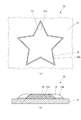
図1(a)は、本実施の形態に係る樹脂盛装飾物10の一部分の正面図である。図1(b)は、樹脂盛装飾物10の一部分の底面断面図である。
FIG. 1A is a front view of a part of a
図1に示すように、樹脂盛装飾物10は、合成樹脂12aを山盛りにした装飾である樹脂盛12が対象物11上に形成された物である。樹脂盛装飾物10は、対象物11と、対象物11上に形成された樹脂盛12と、樹脂盛12のもとになる液体状の材料である液体材料に対して対象物11より高い撥液性を有する枠であって、この液体材料を撥液性によって塞き止める撥液枠13とを備えている。ここで、撥液枠13が固体である場合、撥液枠13の臨界表面張力は、対象物11の臨界表面張力と、樹脂盛12のもとになる液体材料の表面張力との両方より小さい。
As shown in FIG. 1, the
対象物11は、例えば、合成樹脂などの材料で形成されている。対象物11は、例えば、スマートフォン用のカバーなどの物である。
The
樹脂盛12は、例えば無色透明な合成樹脂12aによって形成されている。
The
撥液枠13は、紫外線硬化型のインク13aが対象物11上にUVインクジェット印刷されて形成されている。インク13aは、例えば無色透明なインクである。
The liquid
ここで、インク13aは、樹脂盛12のもとになる液体材料に対して対象物11より高い撥液性を有する液体であり、本発明の撥液性液体を構成している。
Here, the
次に、樹脂盛装飾物10の製造に使用されるインクジェットプリンターの構成について説明する。
Next, the structure of the inkjet printer used for manufacture of the
図2は、樹脂盛装飾物10の製造に使用されるインクジェットプリンター20の斜視図である。
FIG. 2 is a perspective view of the
図2に示すように、インクジェットプリンター20は、対象物11を載せるテーブル21と、矢印20aで示す主走査方向に延在する本体22とを備えている。インクジェットプリンター20は、入力されたデータに基づいた形状に自動的に液体を塗布する装置であり、本発明の自動塗布装置を構成している。
As shown in FIG. 2, the
テーブル21は、矢印20bで示す副走査方向に延在していて本体22を矢印20bで示す副走査方向に移動可能に支持しているガイド機構21aを、矢印20aで示す主走査方向における両側に備えている。
The table 21 extends in the sub-scanning direction indicated by the
本体22は、矢印20aで示す主走査方向に延在しているガイドレール23と、矢印20aで示す主走査方向に移動可能にガイドレール23に支持されているキャリッジ24とを備えている。キャリッジ24は、インク13a(図1参照。)の滴をテーブル21に向けて吐出するための図示していない記録ヘッドと、記録ヘッドによって吐出されたインク13aを硬化させるための紫外線をテーブル21に向けて照射するための図示していないLED(Light Emitting Diode)とを搭載している。
The main body 22 includes a
次に、樹脂盛12によって対象物11に装飾を施す樹脂盛装飾方法、すなわち、樹脂盛装飾物10の製造方法について説明する。
Next, a resin peak decoration method for decorating the
1.撥液枠生成ステップ
作業者は、対象物11をインクジェットプリンター20のテーブル21の所定の位置に固定し、任意の印刷データに基づいた画像を対象物11上に記録するように、インクジェットプリンター20に指示する。
1. Liquid repellent frame generation step The operator fixes the
作業者から指示を受けたインクジェットプリンター20は、テーブル21に対してキャリッジ24をガイドレール23に沿って矢印20aで示す主走査方向に移動するとともに、テーブル21に対して本体22をガイド機構21aに沿って矢印20bで示す副走査方向に移動する。すなわち、インクジェットプリンター20は、テーブル21上に固定された対象物11に対してキャリッジ24を印刷データに応じて移動する。そして、インクジェットプリンター20は、テーブル21上に固定された対象物11上に向けてキャリッジ24上の記録ヘッドによってインク13aを吐出するとともに、対象物11上に吐出されたインク13aに向けてキャリッジ24上のLEDによって紫外線を照射する。すなわち、インクジェットプリンター20は、印刷データに基づいた画像の形でインク13aを対象物11上にUVインクジェット印刷することによって、インク13aによる撥液枠13を対象物11上に生成する。
Upon receiving an instruction from the operator, the
図3(a)は、撥液枠13が生成された対象物11の一部分の正面図である。図3(b)は、図3(a)に示す対象物11の一部分の底面断面図である。
FIG. 3A is a front view of a part of the
撥液枠生成ステップによって撥液枠13が生成された対象物11は、例えば図3に示すようになる。
The
2.材料滴下ステップ
作業者は、撥液枠生成ステップの後、インクジェットプリンター20のテーブル21から対象物11を取り外し、対象物11上において撥液枠生成ステップによって生成された撥液枠13の内側に樹脂盛12のもとになる液体材料を手作業で滴下する。撥液枠13の内側に滴下された液体材料は、撥液枠13の撥液性によって撥液枠13を乗り越えることなく、撥液枠13の内側で硬化して図1に示すように樹脂盛12になる。そして、樹脂盛12が完成すると、樹脂盛装飾物10は完成する。
2. Material dropping step After the liquid repellent frame generating step, the operator removes the
以上に説明したように、本実施の形態に係る樹脂盛装飾方法は、樹脂盛12のもとになる液体材料に対して対象物11より高い撥液性を有する撥液枠13、すなわち、対象物11の臨界表面張力と、この液体材料の表面張力との両方より小さい臨界表面張力を有する撥液枠13の内側に、この液体材料を滴下するので、撥液枠13の形状に応じた自由な形状で樹脂盛12を対象物11上に形成することができる。
As described above, the resin embellishment method according to the present embodiment is the liquid
また、本実施の形態に係る樹脂盛装飾方法は、インクジェットプリンター20の印刷機能によるインク13aの塗布によって撥液枠13を高精度に生成することができるので、樹脂盛12を対象物11上に高精度に形成することができる。
Moreover, since the resin embellishment method according to the present embodiment can generate the liquid
なお、本実施の形態に係る樹脂盛装飾方法は、インクジェットプリンター20の印刷機能によってインク13aを対象物11に塗布するようになっているが、インクジェットプリンター20以外の自動塗布装置によってインク13aを対象物11に塗布するようになっていても良い。
In the resin embellishment method according to the present embodiment, the
本実施の形態に係る樹脂盛装飾方法は、インクジェットプリンター20以外の自動塗布装置によってインク13aを対象物11に塗布するようになっている場合であっても、自動塗布装置によるインク13aの塗布によって撥液枠13を手作業より高精度に生成することができるので、樹脂盛12を対象物11上に高精度に形成することができる。
In the resin embellishment method according to the present embodiment, even if the
なお、本実施の形態に係る樹脂盛装飾方法は、例えば筆などの道具を用いた作業者の手作業によってインク13aを対象物11に塗布するようになっていても良い。
In the resin embellishment method according to the present embodiment, the
また、本実施の形態に係る樹脂盛装飾方法は、作業者の手作業で樹脂盛12のもとになる液体材料を対象物11上に滴下するようになっているが、この液体材料を専用の装置によって対象物11上に滴下するようになっていても良い。
Further, in the resin embellishment method according to the present embodiment, the liquid material that becomes the basis of the
インク13aは、本実施の形態において紫外線硬化型のインクであるが、ソルベントインクなど、紫外線硬化型のインク以外のインクであっても良い。
The
インク13aは、樹脂盛12のもとになる液体材料に対する撥液性を向上するために、シリコン系の界面活性剤、フッ素系の界面活性剤など、界面活性剤が混入されていると良い。また、インク13aは、樹脂盛12のもとになる液体材料に対する撥液性を向上するために、構成する物質の分子の中にフッ素基が含まれていると良い。
The
本発明の撥液性液体は、本実施の形態においてインク13aによって生成されているが、樹脂盛12のもとになる液体材料に対して対象物11より高い撥液性を有する液体であれば、油など、インク以外の液体であっても良い。
The liquid repellent liquid of the present invention is generated by the
(第2の実施の形態)
まず、本実施の形態に係る樹脂盛装飾物の構成について説明する。
(Second Embodiment)
First, the structure of the resin embellishment according to the present embodiment will be described.
なお、本実施の形態に係る樹脂盛装飾物の構成のうち第1の実施の形態に係る樹脂盛装飾物10(図1参照。)の構成と同様の構成については、樹脂盛装飾物10の構成と同一の符号を付して詳細な説明を省略する。
In addition, about the structure similar to the structure of the resin embellishment 10 (refer FIG. 1) which concerns on 1st Embodiment among the structures of the resin embellishment which concerns on this Embodiment, it is the same as the structure of the
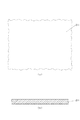
図4(a)は、本実施の形態に係る樹脂盛装飾物110の一部分の正面図である。図4(b)は、樹脂盛装飾物110の一部分の底面断面図である。
FIG. 4A is a front view of a part of the
図4に示すように、樹脂盛装飾物110の構成は、樹脂盛装飾物10が撥液枠13(図1参照。)を備えていない構成と同様である。
As shown in FIG. 4, the configuration of the
次に、樹脂盛12によって対象物11に装飾を施す樹脂盛装飾方法、すなわち、樹脂盛装飾物110の製造方法について説明する。
Next, a resin peak decoration method for decorating the
1.撥液枠生成ステップ
インクジェットプリンター20は、第1の実施の形態と同様に、作業者からの指示に応じて、印刷データに基づいた画像の形で油113a(図5参照。)を対象物11上に印刷することによって、油113aによる撥液枠113(図5参照。)を対象物11上に生成する。
1. Liquid repellent frame generation step As in the first embodiment, the
図5(a)は、撥液枠113が生成された対象物11の一部分の正面図である。図5(b)は、図5(a)に示す対象物11の一部分の底面断面図である。
FIG. 5A is a front view of a part of the
撥液枠生成ステップによって撥液枠113が生成された対象物11は、例えば図5に示すようになる。
The
なお、油113aは、樹脂盛12のもとになる液体材料に対して対象物11より高い撥液性を有する液体であり、本発明の撥液性液体を構成している。すなわち、撥液枠113は、樹脂盛12のもとになる液体材料に対して対象物11より高い撥液性を有し、この液体材料を撥液性によって塞き止める枠である。
The
2.材料滴下ステップ
作業者は、撥液枠生成ステップの後、インクジェットプリンター20のテーブル21から対象物11を取り外し、対象物11上において撥液枠生成ステップによって生成された撥液枠113の内側に樹脂盛12のもとになる液体材料を手作業または専用の装置で滴下する。撥液枠113の内側に滴下された液体材料は、撥液枠113の撥液性によって撥液枠113を乗り越えることなく、撥液枠113の内側で硬化して樹脂盛12になる。
2. Material dropping step After the liquid repellent frame generating step, the operator removes the
図6(a)は、樹脂盛12が形成された対象物11の一部分の正面図である。図6(b)は、図6(a)に示す対象物11の一部分の底面断面図である。
FIG. 6A is a front view of a part of the
材料滴下ステップによって撥液枠113の内側に樹脂盛12のもとになる液体材料が滴下された対象物11は、例えば図6に示すようになる。
The
3.撥液枠除去ステップ
次いで、作業者は、材料滴下ステップによって滴下された液体材料が硬化した後、対象物11上の撥液枠113を拭き取るなどして除去する。したがって、図4に示すように樹脂盛装飾物110が完成する。
3. Liquid Repellent Frame Removal Step Next, the operator removes the liquid
以上に説明したように、本実施の形態に係る樹脂盛装飾方法は、樹脂盛12のもとになる液体材料に対して対象物11より高い撥液性を有する撥液枠113の内側に、この液体材料を滴下するので、撥液枠113の形状に応じた自由な形状で樹脂盛12を対象物11上に形成することができる。
As described above, the resin embellishment method according to the present embodiment is arranged on the inner side of the liquid
また、本実施の形態に係る樹脂盛装飾方法は、滴下された液体材料が硬化して樹脂盛12が形成された後で撥液枠113を除去することができるので、撥液枠113が存在しない状態で樹脂盛12による装飾を対象物11上に表すことができる。
Further, the resin embellishment method according to the present embodiment allows the liquid
また、本実施の形態に係る樹脂盛装飾方法は、第1の実施の形態に係る樹脂盛装飾方法と同様に、インクジェットプリンター20以外の自動塗布装置によって油113aを対象物11に塗布するようになっていても良いし、例えば筆などの道具を用いた作業者の手作業によって油113aを対象物11に塗布するようになっていても良い。
Further, in the resin embellishment method according to the present embodiment, the
(第3の実施の形態)
まず、本実施の形態に係る樹脂盛装飾物の構成について説明する。
(Third embodiment)
First, the structure of the resin embellishment according to the present embodiment will be described.
なお、本実施の形態に係る樹脂盛装飾物の構成のうち第1の実施の形態に係る樹脂盛装飾物10(図1参照。)の構成と同様の構成については、樹脂盛装飾物10の構成と同一の符号を付して詳細な説明を省略する。
In addition, about the structure similar to the structure of the resin embellishment 10 (refer FIG. 1) which concerns on 1st Embodiment among the structures of the resin embellishment which concerns on this Embodiment, it is the same as the structure of the
図7(a)は、本実施の形態に係る樹脂盛装飾物210の一部分の正面図である。図7(b)は、樹脂盛装飾物210の一部分の底面断面図である。
FIG. 7A is a front view of a portion of the
図7に示すように、樹脂盛装飾物210の構成は、樹脂盛装飾物10が対象物211および撥液枠213を対象物11(図1参照。)および撥液枠13(図1参照。)に代えて備えている構成と同様である。
As shown in FIG. 7, the
対象物211の構成は、対象物11がその一部を撥液枠213に置き換えた構成と同様である。対象物211は、表面がレーザーで焼かれることによって、表面のうちレーザーで焼かれた部分において、樹脂盛12のもとになる液体材料に対する撥液性が向上する。
The configuration of the
撥液枠213は、樹脂盛12のもとになる液体材料に対して対象物211より高い撥液性を有し、この液体材料を撥液性によって塞き止める枠である。ここで、撥液枠213の臨界表面張力は、対象物211の臨界表面張力と、樹脂盛12のもとになる液体材料の表面張力との両方より小さい。
The liquid
次に、樹脂盛12によって対象物211に装飾を施す樹脂盛装飾方法、すなわち、樹脂盛装飾物210の製造方法について説明する。
Next, a resin peak decoration method for decorating the
1.撥液枠生成ステップ
樹脂盛装飾物210の製造には、レーザー加工機が使用される。レーザー加工機は、入力されたデータに基づいた形状に自動的にレーザーを照射する装置である。
1. Liquid repellent frame generation step A laser processing machine is used to manufacture the
図8(a)は、加工される前の対象物211の一部分の正面図である。図8(b)は、図8(a)に示す対象物211の一部分の底面断面図である。
FIG. 8A is a front view of a part of the
作業者は、図8に示す対象物211をレーザー加工機の所定の位置に固定し、任意のデータに基づいた形状に対象物211の表面をレーザーで焼くように、レーザー加工機に指示する。
The operator instructs the laser processing machine to fix the
図9(a)は、撥液枠213が生成された対象物211の一部分の正面図である。図9(b)は、図9(a)に示す対象物211の一部分の底面断面図である。
FIG. 9A is a front view of a part of the
作業者から指示を受けたレーザー加工機は、入力されたデータに基づいた形状に対象物211の表面をレーザーで焼くことによって、図9に示すように、対象物211の表面のうちレーザーで焼かれた部分による撥液枠213を生成する。
Upon receiving an instruction from the operator, the laser beam machine burns the surface of the
2.材料滴下ステップ
作業者は、撥液枠生成ステップの後、レーザー加工機から対象物211を取り外し、対象物211上において撥液枠生成ステップによって生成された撥液枠213の内側に樹脂盛12のもとになる液体材料を手作業または専用の装置で滴下する。撥液枠213の内側に滴下された液体材料は、撥液枠213の撥液性によって撥液枠213を乗り越えることなく、撥液枠213の内側で硬化して図7に示すように樹脂盛12になる。そして、樹脂盛12が完成すると、樹脂盛装飾物210は完成する。
2. Material dropping step After the liquid repellent frame generating step, the operator removes the
以上に説明したように、本実施の形態に係る樹脂盛装飾方法は、樹脂盛12のもとになる液体材料に対して対象物211より高い撥液性を有する撥液枠213、すなわち、対象物211の臨界表面張力と、この液体材料の表面張力との両方より小さい臨界表面張力を有する撥液枠213の内側に、この液体材料を滴下するので、撥液枠213の形状に応じた自由な形状で樹脂盛12を対象物211上に形成することができる。
As described above, the resin embellishment method according to the present embodiment is a liquid
また、本実施の形態に係る樹脂盛装飾方法は、レーザー加工機によって対象物211の表面をレーザーで焼くことによって撥液枠213を手作業より高精度に生成することができるので、樹脂盛12を対象物211上に高精度に形成することができる。
In the resin embellishment method according to the present embodiment, the liquid
なお、本実施の形態に係る樹脂盛装飾方法は、作業者の手作業によって対象物211の表面をレーザーで焼くようになっていても良い。
The resin embellishment method according to the present embodiment may be configured such that the surface of the
11 対象物
12 樹脂盛
12a 合成樹脂
13 撥液枠
13a インク(撥液性液体)
20 インクジェットプリンター(自動塗布装置)
113 撥液枠
113a 油(撥液性液体)
211 対象物
213 撥液枠
DESCRIPTION OF
20 Inkjet printer (automatic coating device)
113
Claims (4)
前記樹脂盛のもとになる液体状の材料である液体材料を撥液性によって弾かれて塞き止める枠である撥液枠を紫外線硬化型のインクに紫外線を照射するUVインクジェット印刷によって前記対象物上に生成する撥液枠生成ステップと、前記対象物上において前記撥液枠生成ステップによって生成された前記撥液枠の内側に前記液体材料を滴下する材料滴下ステップとを備えており、
前記液体材料に対する硬化後の前記撥液枠の撥液性は、前記液体材料に対する前記対象物の撥液性より高いことを特徴とする樹脂盛装飾方法。 A resin embellishment method for forming a resin heap, which is a decoration made of synthetic resin, on an object,
The liquid repellent frame, which is a liquid material that is a liquid material that is the basis of the resin deposit , is blocked by being repelled by the liquid repellent property, and the target is obtained by UV ink jet printing that irradiates ultraviolet curable ink with ultraviolet light. A liquid repellent frame generating step generated on the object, and a material dropping step of dropping the liquid material on the inside of the liquid repellent frame generated by the liquid repellent frame generating step on the object ,
A resin embellishment decoration method , wherein the liquid repellency of the liquid repellent frame after curing with respect to the liquid material is higher than the liquid repellency of the object with respect to the liquid material .
前記樹脂盛のもとになる液体状の材料である液体材料の表面張力より小さい臨界表面張力を有する枠である撥液枠を紫外線硬化型のインクに紫外線を照射するUVインクジェット印刷によって前記対象物上に生成する撥液枠生成ステップと、前記対象物上において前記撥液枠生成ステップによって生成された前記撥液枠の内側に前記液体材料を滴下する材料滴下ステップとを備えており、
硬化後の前記撥液枠の臨界表面張力は、前記対象物の臨界表面張力より小さいことを特徴とする樹脂盛装飾方法。 A resin embellishment method for forming a resin heap, which is a decoration made of synthetic resin, on an object,
Wherein the UV ink jet printing a lyophobic frame is a frame having a small critical surface tension Ri by the surface tension of the liquid material is a liquid material underlying the previous SL resin Sheng is irradiated with ultraviolet rays to ultraviolet curable ink A liquid repellent frame generating step generated on an object, and a material dropping step of dropping the liquid material on the inside of the liquid repellent frame generated by the liquid repellent frame generating step on the object ,
The resin embellishment decoration method characterized by the critical surface tension of the said liquid repellent frame after hardening being smaller than the critical surface tension of the said target object .
前記樹脂盛装飾方法は、前記材料滴下ステップによって滴下された前記液体材料が硬化して前記樹脂盛が形成された後に前記撥液枠を除去する前記撥液枠除去ステップを備えていることを特徴とする請求項1または請求項2に記載の樹脂盛装飾方法。 The resin embellishment method includes the liquid repellent frame removing step of removing the liquid repellent frame after the liquid material dropped by the material dropping step is cured and the resin heap is formed. The resin embellishment decoration method of Claim 1 or Claim 2.
Priority Applications (3)
| Application Number | Priority Date | Filing Date | Title |
|---|---|---|---|
| JP2012266803A JP6473285B2 (en) | 2012-12-05 | 2012-12-05 | Resin pile decoration method |
| CN201380063448.1A CN104870202A (en) | 2012-12-05 | 2013-12-03 | Ornamenting method using resin potting |
| PCT/JP2013/082418 WO2014087982A1 (en) | 2012-12-05 | 2013-12-03 | Ornamenting method using resin potting |
Applications Claiming Priority (1)
| Application Number | Priority Date | Filing Date | Title |
|---|---|---|---|
| JP2012266803A JP6473285B2 (en) | 2012-12-05 | 2012-12-05 | Resin pile decoration method |
Publications (2)
| Publication Number | Publication Date |
|---|---|
| JP2014111342A JP2014111342A (en) | 2014-06-19 |
| JP6473285B2 true JP6473285B2 (en) | 2019-02-20 |
Family
ID=50883399
Family Applications (1)
| Application Number | Title | Priority Date | Filing Date |
|---|---|---|---|
| JP2012266803A Active JP6473285B2 (en) | 2012-12-05 | 2012-12-05 | Resin pile decoration method |
Country Status (3)
| Country | Link |
|---|---|
| JP (1) | JP6473285B2 (en) |
| CN (1) | CN104870202A (en) |
| WO (1) | WO2014087982A1 (en) |
Families Citing this family (2)
| Publication number | Priority date | Publication date | Assignee | Title |
|---|---|---|---|---|
| JP2016029224A (en) * | 2014-07-25 | 2016-03-03 | 株式会社ミマキエンジニアリング | Dyeing method, mask forming apparatus, and method for manufacturing colored article |
| WO2020089491A1 (en) * | 2018-10-31 | 2020-05-07 | Barberan Latorre Jesus Francisco | Method for producing a three-dimensional structure on a surface of a flat substrate, resulting substrate, and device for producing the substrate according to the method |
Family Cites Families (11)
| Publication number | Priority date | Publication date | Assignee | Title |
|---|---|---|---|---|
| JPS4716629Y1 (en) * | 1966-02-15 | 1972-06-10 | ||
| JPS6018982B2 (en) * | 1975-06-04 | 1985-05-14 | 東洋紡績株式会社 | How to draw on objects with smooth surfaces |
| JP2001315288A (en) * | 2000-05-11 | 2001-11-13 | Toppan Printing Co Ltd | Decorative material |
| JP3691030B2 (en) * | 2002-07-01 | 2005-08-31 | 大日本インキ化学工業株式会社 | Water pressure transfer film and method for producing water pressure transfer body using the same |
| JP2005142118A (en) * | 2003-11-10 | 2005-06-02 | Seiko Epson Corp | Manufacturing method for substrate device |
| JP2007057217A (en) * | 2005-08-25 | 2007-03-08 | Kazuyoshi Nakajima | Photograph (image)-containing lighter and lighter case |
| JP2008264275A (en) * | 2007-04-23 | 2008-11-06 | Kiyomitsu Watanabe | Ornament and ornament manufacturing method |
| JP2008275471A (en) * | 2007-04-27 | 2008-11-13 | Seiko Epson Corp | Dial for timepiece, its manufacturing method, and timepiece |
| EP2011629A1 (en) * | 2007-07-03 | 2009-01-07 | F. Hoffman-la Roche AG | Method for manufacturing a microfluid system on a polymer surface |
| JP2009190297A (en) * | 2008-02-15 | 2009-08-27 | Seiko Epson Corp | Masking method and masking device |
| JP5339069B2 (en) * | 2008-03-31 | 2013-11-13 | 大日本印刷株式会社 | Decorative sheet and decorative material on which it is laminated |
-
2012
- 2012-12-05 JP JP2012266803A patent/JP6473285B2/en active Active
-
2013
- 2013-12-03 WO PCT/JP2013/082418 patent/WO2014087982A1/en active Application Filing
- 2013-12-03 CN CN201380063448.1A patent/CN104870202A/en active Pending
Also Published As
| Publication number | Publication date |
|---|---|
| CN104870202A (en) | 2015-08-26 |
| JP2014111342A (en) | 2014-06-19 |
| WO2014087982A1 (en) | 2014-06-12 |
Similar Documents
| Publication | Publication Date | Title |
|---|---|---|
| JP6590473B2 (en) | Three-dimensional object forming apparatus and three-dimensional object forming method | |
| JP5112360B2 (en) | Inkjet printer and printing method | |
| JP5615822B2 (en) | Inkjet printer and inkjet printing method | |
| EP3323599B1 (en) | Forming device and forming method | |
| JP6550280B2 (en) | Forming apparatus and forming method | |
| WO2017029816A2 (en) | Information processing device, image forming apparatus, method for manufacturing output object, and computer-readable recording medium | |
| JP6473285B2 (en) | Resin pile decoration method | |
| JP6041658B2 (en) | Resin pile decoration method | |
| JP6293151B2 (en) | Method for applying curable liquid and apparatus for performing the method | |
| JP6301161B2 (en) | Inkjet printing device | |
| JP5899794B2 (en) | Manufacturing method of printed matter, printed matter | |
| JP5216156B2 (en) | Inkjet printer, printing unit and printing method therefor | |
| JP5929261B2 (en) | Printing apparatus, printing method, and printed matter | |
| JP2010131773A (en) | Head device and apparatus with the head device | |
| JP2009190297A (en) | Masking method and masking device | |
| JP2007210111A (en) | Image forming apparatus | |
| JP7135683B2 (en) | LIQUID EJECTION APPARATUS, METHOD AND PROGRAM | |
| JP7115157B2 (en) | Discharge device, image forming device, curing method and program | |
| WO2017002926A1 (en) | Molding device and molding method | |
| JP2014104677A (en) | Liquid discharge device and jig for three-dimensional shape printed matter | |
| JP7172671B2 (en) | Liquid ejection device and control method | |
| JP6406749B2 (en) | inkjet printer | |
| CN111183038B (en) | Ejection apparatus, image forming apparatus, curing method, and computer readable medium | |
| JP2008284737A (en) | Optical irradiating apparatus and liquid jetting apparatus | |
| JP2009176855A (en) | Marking method and marking apparatus |
Legal Events
| Date | Code | Title | Description |
|---|---|---|---|
| A621 | Written request for application examination |
Free format text: JAPANESE INTERMEDIATE CODE: A621 Effective date: 20151118 |
|
| A131 | Notification of reasons for refusal |
Free format text: JAPANESE INTERMEDIATE CODE: A131 Effective date: 20160920 |
|
| A601 | Written request for extension of time |
Free format text: JAPANESE INTERMEDIATE CODE: A601 Effective date: 20161121 |
|
| A02 | Decision of refusal |
Free format text: JAPANESE INTERMEDIATE CODE: A02 Effective date: 20170329 |
|
| A521 | Request for written amendment filed |
Free format text: JAPANESE INTERMEDIATE CODE: A523 Effective date: 20170629 |
|
| A911 | Transfer to examiner for re-examination before appeal (zenchi) |
Free format text: JAPANESE INTERMEDIATE CODE: A911 Effective date: 20170707 |
|
| A912 | Re-examination (zenchi) completed and case transferred to appeal board |
Free format text: JAPANESE INTERMEDIATE CODE: A912 Effective date: 20170721 |
|
| A521 | Request for written amendment filed |
Free format text: JAPANESE INTERMEDIATE CODE: A523 Effective date: 20181022 |
|
| A61 | First payment of annual fees (during grant procedure) |
Free format text: JAPANESE INTERMEDIATE CODE: A61 Effective date: 20190125 |
|
| R150 | Certificate of patent or registration of utility model |
Ref document number: 6473285 Country of ref document: JP Free format text: JAPANESE INTERMEDIATE CODE: R150 |
|
| R250 | Receipt of annual fees |
Free format text: JAPANESE INTERMEDIATE CODE: R250 |
|
| R250 | Receipt of annual fees |
Free format text: JAPANESE INTERMEDIATE CODE: R250 |
|
| R250 | Receipt of annual fees |
Free format text: JAPANESE INTERMEDIATE CODE: R250 |