JP6466409B2 - Excavator - Google Patents
Excavator Download PDFInfo
- Publication number
- JP6466409B2 JP6466409B2 JP2016511558A JP2016511558A JP6466409B2 JP 6466409 B2 JP6466409 B2 JP 6466409B2 JP 2016511558 A JP2016511558 A JP 2016511558A JP 2016511558 A JP2016511558 A JP 2016511558A JP 6466409 B2 JP6466409 B2 JP 6466409B2
- Authority
- JP
- Japan
- Prior art keywords
- storage system
- power storage
- turning
- power
- motor
- Prior art date
- Legal status (The legal status is an assumption and is not a legal conclusion. Google has not performed a legal analysis and makes no representation as to the accuracy of the status listed.)
- Active
Links
Images


Classifications
-
- E—FIXED CONSTRUCTIONS
- E02—HYDRAULIC ENGINEERING; FOUNDATIONS; SOIL SHIFTING
- E02F—DREDGING; SOIL-SHIFTING
- E02F9/00—Component parts of dredgers or soil-shifting machines, not restricted to one of the kinds covered by groups E02F3/00 - E02F7/00
- E02F9/08—Superstructures; Supports for superstructures
- E02F9/10—Supports for movable superstructures mounted on travelling or walking gears or on other superstructures
- E02F9/12—Slewing or traversing gears
- E02F9/121—Turntables, i.e. structure rotatable about 360°
- E02F9/123—Drives or control devices specially adapted therefor
-
- B—PERFORMING OPERATIONS; TRANSPORTING
- B60—VEHICLES IN GENERAL
- B60K—ARRANGEMENT OR MOUNTING OF PROPULSION UNITS OR OF TRANSMISSIONS IN VEHICLES; ARRANGEMENT OR MOUNTING OF PLURAL DIVERSE PRIME-MOVERS IN VEHICLES; AUXILIARY DRIVES FOR VEHICLES; INSTRUMENTATION OR DASHBOARDS FOR VEHICLES; ARRANGEMENTS IN CONNECTION WITH COOLING, AIR INTAKE, GAS EXHAUST OR FUEL SUPPLY OF PROPULSION UNITS IN VEHICLES
- B60K6/00—Arrangement or mounting of plural diverse prime-movers for mutual or common propulsion, e.g. hybrid propulsion systems comprising electric motors and internal combustion engines ; Control systems therefor, i.e. systems controlling two or more prime movers, or controlling one of these prime movers and any of the transmission, drive or drive units Informative references: mechanical gearings with secondary electric drive F16H3/72; arrangements for handling mechanical energy structurally associated with the dynamo-electric machine H02K7/00; machines comprising structurally interrelated motor and generator parts H02K51/00; dynamo-electric machines not otherwise provided for in H02K see H02K99/00
- B60K6/20—Arrangement or mounting of plural diverse prime-movers for mutual or common propulsion, e.g. hybrid propulsion systems comprising electric motors and internal combustion engines ; Control systems therefor, i.e. systems controlling two or more prime movers, or controlling one of these prime movers and any of the transmission, drive or drive units Informative references: mechanical gearings with secondary electric drive F16H3/72; arrangements for handling mechanical energy structurally associated with the dynamo-electric machine H02K7/00; machines comprising structurally interrelated motor and generator parts H02K51/00; dynamo-electric machines not otherwise provided for in H02K see H02K99/00 the prime-movers consisting of electric motors and internal combustion engines, e.g. HEVs
- B60K6/42—Arrangement or mounting of plural diverse prime-movers for mutual or common propulsion, e.g. hybrid propulsion systems comprising electric motors and internal combustion engines ; Control systems therefor, i.e. systems controlling two or more prime movers, or controlling one of these prime movers and any of the transmission, drive or drive units Informative references: mechanical gearings with secondary electric drive F16H3/72; arrangements for handling mechanical energy structurally associated with the dynamo-electric machine H02K7/00; machines comprising structurally interrelated motor and generator parts H02K51/00; dynamo-electric machines not otherwise provided for in H02K see H02K99/00 the prime-movers consisting of electric motors and internal combustion engines, e.g. HEVs characterised by the architecture of the hybrid electric vehicle
- B60K6/48—Parallel type
- B60K6/485—Motor-assist type
-
- B—PERFORMING OPERATIONS; TRANSPORTING
- B60—VEHICLES IN GENERAL
- B60L—PROPULSION OF ELECTRICALLY-PROPELLED VEHICLES; SUPPLYING ELECTRIC POWER FOR AUXILIARY EQUIPMENT OF ELECTRICALLY-PROPELLED VEHICLES; ELECTRODYNAMIC BRAKE SYSTEMS FOR VEHICLES IN GENERAL; MAGNETIC SUSPENSION OR LEVITATION FOR VEHICLES; MONITORING OPERATING VARIABLES OF ELECTRICALLY-PROPELLED VEHICLES; ELECTRIC SAFETY DEVICES FOR ELECTRICALLY-PROPELLED VEHICLES
- B60L3/00—Electric devices on electrically-propelled vehicles for safety purposes; Monitoring operating variables, e.g. speed, deceleration or energy consumption
- B60L3/0023—Detecting, eliminating, remedying or compensating for drive train abnormalities, e.g. failures within the drive train
- B60L3/0046—Detecting, eliminating, remedying or compensating for drive train abnormalities, e.g. failures within the drive train relating to electric energy storage systems, e.g. batteries or capacitors
-
- B—PERFORMING OPERATIONS; TRANSPORTING
- B60—VEHICLES IN GENERAL
- B60L—PROPULSION OF ELECTRICALLY-PROPELLED VEHICLES; SUPPLYING ELECTRIC POWER FOR AUXILIARY EQUIPMENT OF ELECTRICALLY-PROPELLED VEHICLES; ELECTRODYNAMIC BRAKE SYSTEMS FOR VEHICLES IN GENERAL; MAGNETIC SUSPENSION OR LEVITATION FOR VEHICLES; MONITORING OPERATING VARIABLES OF ELECTRICALLY-PROPELLED VEHICLES; ELECTRIC SAFETY DEVICES FOR ELECTRICALLY-PROPELLED VEHICLES
- B60L3/00—Electric devices on electrically-propelled vehicles for safety purposes; Monitoring operating variables, e.g. speed, deceleration or energy consumption
- B60L3/04—Cutting off the power supply under fault conditions
-
- B—PERFORMING OPERATIONS; TRANSPORTING
- B60—VEHICLES IN GENERAL
- B60L—PROPULSION OF ELECTRICALLY-PROPELLED VEHICLES; SUPPLYING ELECTRIC POWER FOR AUXILIARY EQUIPMENT OF ELECTRICALLY-PROPELLED VEHICLES; ELECTRODYNAMIC BRAKE SYSTEMS FOR VEHICLES IN GENERAL; MAGNETIC SUSPENSION OR LEVITATION FOR VEHICLES; MONITORING OPERATING VARIABLES OF ELECTRICALLY-PROPELLED VEHICLES; ELECTRIC SAFETY DEVICES FOR ELECTRICALLY-PROPELLED VEHICLES
- B60L50/00—Electric propulsion with power supplied within the vehicle
- B60L50/40—Electric propulsion with power supplied within the vehicle using propulsion power supplied by capacitors
-
- B—PERFORMING OPERATIONS; TRANSPORTING
- B60—VEHICLES IN GENERAL
- B60L—PROPULSION OF ELECTRICALLY-PROPELLED VEHICLES; SUPPLYING ELECTRIC POWER FOR AUXILIARY EQUIPMENT OF ELECTRICALLY-PROPELLED VEHICLES; ELECTRODYNAMIC BRAKE SYSTEMS FOR VEHICLES IN GENERAL; MAGNETIC SUSPENSION OR LEVITATION FOR VEHICLES; MONITORING OPERATING VARIABLES OF ELECTRICALLY-PROPELLED VEHICLES; ELECTRIC SAFETY DEVICES FOR ELECTRICALLY-PROPELLED VEHICLES
- B60L58/00—Methods or circuit arrangements for monitoring or controlling batteries or fuel cells, specially adapted for electric vehicles
- B60L58/10—Methods or circuit arrangements for monitoring or controlling batteries or fuel cells, specially adapted for electric vehicles for monitoring or controlling batteries
- B60L58/12—Methods or circuit arrangements for monitoring or controlling batteries or fuel cells, specially adapted for electric vehicles for monitoring or controlling batteries responding to state of charge [SoC]
- B60L58/13—Maintaining the SoC within a determined range
-
- B—PERFORMING OPERATIONS; TRANSPORTING
- B60—VEHICLES IN GENERAL
- B60L—PROPULSION OF ELECTRICALLY-PROPELLED VEHICLES; SUPPLYING ELECTRIC POWER FOR AUXILIARY EQUIPMENT OF ELECTRICALLY-PROPELLED VEHICLES; ELECTRODYNAMIC BRAKE SYSTEMS FOR VEHICLES IN GENERAL; MAGNETIC SUSPENSION OR LEVITATION FOR VEHICLES; MONITORING OPERATING VARIABLES OF ELECTRICALLY-PROPELLED VEHICLES; ELECTRIC SAFETY DEVICES FOR ELECTRICALLY-PROPELLED VEHICLES
- B60L58/00—Methods or circuit arrangements for monitoring or controlling batteries or fuel cells, specially adapted for electric vehicles
- B60L58/10—Methods or circuit arrangements for monitoring or controlling batteries or fuel cells, specially adapted for electric vehicles for monitoring or controlling batteries
- B60L58/12—Methods or circuit arrangements for monitoring or controlling batteries or fuel cells, specially adapted for electric vehicles for monitoring or controlling batteries responding to state of charge [SoC]
- B60L58/14—Preventing excessive discharging
-
- B—PERFORMING OPERATIONS; TRANSPORTING
- B60—VEHICLES IN GENERAL
- B60L—PROPULSION OF ELECTRICALLY-PROPELLED VEHICLES; SUPPLYING ELECTRIC POWER FOR AUXILIARY EQUIPMENT OF ELECTRICALLY-PROPELLED VEHICLES; ELECTRODYNAMIC BRAKE SYSTEMS FOR VEHICLES IN GENERAL; MAGNETIC SUSPENSION OR LEVITATION FOR VEHICLES; MONITORING OPERATING VARIABLES OF ELECTRICALLY-PROPELLED VEHICLES; ELECTRIC SAFETY DEVICES FOR ELECTRICALLY-PROPELLED VEHICLES
- B60L58/00—Methods or circuit arrangements for monitoring or controlling batteries or fuel cells, specially adapted for electric vehicles
- B60L58/10—Methods or circuit arrangements for monitoring or controlling batteries or fuel cells, specially adapted for electric vehicles for monitoring or controlling batteries
- B60L58/12—Methods or circuit arrangements for monitoring or controlling batteries or fuel cells, specially adapted for electric vehicles for monitoring or controlling batteries responding to state of charge [SoC]
- B60L58/15—Preventing overcharging
-
- B—PERFORMING OPERATIONS; TRANSPORTING
- B60—VEHICLES IN GENERAL
- B60W—CONJOINT CONTROL OF VEHICLE SUB-UNITS OF DIFFERENT TYPE OR DIFFERENT FUNCTION; CONTROL SYSTEMS SPECIALLY ADAPTED FOR HYBRID VEHICLES; ROAD VEHICLE DRIVE CONTROL SYSTEMS FOR PURPOSES NOT RELATED TO THE CONTROL OF A PARTICULAR SUB-UNIT
- B60W20/00—Control systems specially adapted for hybrid vehicles
-
- E—FIXED CONSTRUCTIONS
- E02—HYDRAULIC ENGINEERING; FOUNDATIONS; SOIL SHIFTING
- E02F—DREDGING; SOIL-SHIFTING
- E02F9/00—Component parts of dredgers or soil-shifting machines, not restricted to one of the kinds covered by groups E02F3/00 - E02F7/00
- E02F9/20—Drives; Control devices
- E02F9/2025—Particular purposes of control systems not otherwise provided for
- E02F9/2033—Limiting the movement of frames or implements, e.g. to avoid collision between implements and the cabin
-
- E—FIXED CONSTRUCTIONS
- E02—HYDRAULIC ENGINEERING; FOUNDATIONS; SOIL SHIFTING
- E02F—DREDGING; SOIL-SHIFTING
- E02F9/00—Component parts of dredgers or soil-shifting machines, not restricted to one of the kinds covered by groups E02F3/00 - E02F7/00
- E02F9/20—Drives; Control devices
- E02F9/2058—Electric or electro-mechanical or mechanical control devices of vehicle sub-units
- E02F9/2062—Control of propulsion units
- E02F9/2075—Control of propulsion units of the hybrid type
-
- E—FIXED CONSTRUCTIONS
- E02—HYDRAULIC ENGINEERING; FOUNDATIONS; SOIL SHIFTING
- E02F—DREDGING; SOIL-SHIFTING
- E02F9/00—Component parts of dredgers or soil-shifting machines, not restricted to one of the kinds covered by groups E02F3/00 - E02F7/00
- E02F9/20—Drives; Control devices
- E02F9/2058—Electric or electro-mechanical or mechanical control devices of vehicle sub-units
- E02F9/2095—Control of electric, electro-mechanical or mechanical equipment not otherwise provided for, e.g. ventilators, electro-driven fans
-
- E—FIXED CONSTRUCTIONS
- E02—HYDRAULIC ENGINEERING; FOUNDATIONS; SOIL SHIFTING
- E02F—DREDGING; SOIL-SHIFTING
- E02F9/00—Component parts of dredgers or soil-shifting machines, not restricted to one of the kinds covered by groups E02F3/00 - E02F7/00
- E02F9/20—Drives; Control devices
- E02F9/22—Hydraulic or pneumatic drives
- E02F9/2278—Hydraulic circuits
- E02F9/2285—Pilot-operated systems
-
- E—FIXED CONSTRUCTIONS
- E02—HYDRAULIC ENGINEERING; FOUNDATIONS; SOIL SHIFTING
- E02F—DREDGING; SOIL-SHIFTING
- E02F9/00—Component parts of dredgers or soil-shifting machines, not restricted to one of the kinds covered by groups E02F3/00 - E02F7/00
- E02F9/20—Drives; Control devices
- E02F9/22—Hydraulic or pneumatic drives
- E02F9/2278—Hydraulic circuits
- E02F9/2296—Systems with a variable displacement pump
-
- E—FIXED CONSTRUCTIONS
- E02—HYDRAULIC ENGINEERING; FOUNDATIONS; SOIL SHIFTING
- E02F—DREDGING; SOIL-SHIFTING
- E02F9/00—Component parts of dredgers or soil-shifting machines, not restricted to one of the kinds covered by groups E02F3/00 - E02F7/00
- E02F9/26—Indicating devices
- E02F9/264—Sensors and their calibration for indicating the position of the work tool
- E02F9/265—Sensors and their calibration for indicating the position of the work tool with follow-up actions (e.g. control signals sent to actuate the work tool)
-
- E—FIXED CONSTRUCTIONS
- E02—HYDRAULIC ENGINEERING; FOUNDATIONS; SOIL SHIFTING
- E02F—DREDGING; SOIL-SHIFTING
- E02F9/00—Component parts of dredgers or soil-shifting machines, not restricted to one of the kinds covered by groups E02F3/00 - E02F7/00
- E02F9/26—Indicating devices
- E02F9/267—Diagnosing or detecting failure of vehicles
- E02F9/268—Diagnosing or detecting failure of vehicles with failure correction follow-up actions
-
- B—PERFORMING OPERATIONS; TRANSPORTING
- B60—VEHICLES IN GENERAL
- B60K—ARRANGEMENT OR MOUNTING OF PROPULSION UNITS OR OF TRANSMISSIONS IN VEHICLES; ARRANGEMENT OR MOUNTING OF PLURAL DIVERSE PRIME-MOVERS IN VEHICLES; AUXILIARY DRIVES FOR VEHICLES; INSTRUMENTATION OR DASHBOARDS FOR VEHICLES; ARRANGEMENTS IN CONNECTION WITH COOLING, AIR INTAKE, GAS EXHAUST OR FUEL SUPPLY OF PROPULSION UNITS IN VEHICLES
- B60K6/00—Arrangement or mounting of plural diverse prime-movers for mutual or common propulsion, e.g. hybrid propulsion systems comprising electric motors and internal combustion engines ; Control systems therefor, i.e. systems controlling two or more prime movers, or controlling one of these prime movers and any of the transmission, drive or drive units Informative references: mechanical gearings with secondary electric drive F16H3/72; arrangements for handling mechanical energy structurally associated with the dynamo-electric machine H02K7/00; machines comprising structurally interrelated motor and generator parts H02K51/00; dynamo-electric machines not otherwise provided for in H02K see H02K99/00
- B60K6/20—Arrangement or mounting of plural diverse prime-movers for mutual or common propulsion, e.g. hybrid propulsion systems comprising electric motors and internal combustion engines ; Control systems therefor, i.e. systems controlling two or more prime movers, or controlling one of these prime movers and any of the transmission, drive or drive units Informative references: mechanical gearings with secondary electric drive F16H3/72; arrangements for handling mechanical energy structurally associated with the dynamo-electric machine H02K7/00; machines comprising structurally interrelated motor and generator parts H02K51/00; dynamo-electric machines not otherwise provided for in H02K see H02K99/00 the prime-movers consisting of electric motors and internal combustion engines, e.g. HEVs
- B60K6/42—Arrangement or mounting of plural diverse prime-movers for mutual or common propulsion, e.g. hybrid propulsion systems comprising electric motors and internal combustion engines ; Control systems therefor, i.e. systems controlling two or more prime movers, or controlling one of these prime movers and any of the transmission, drive or drive units Informative references: mechanical gearings with secondary electric drive F16H3/72; arrangements for handling mechanical energy structurally associated with the dynamo-electric machine H02K7/00; machines comprising structurally interrelated motor and generator parts H02K51/00; dynamo-electric machines not otherwise provided for in H02K see H02K99/00 the prime-movers consisting of electric motors and internal combustion engines, e.g. HEVs characterised by the architecture of the hybrid electric vehicle
- B60K6/48—Parallel type
- B60K2006/4825—Electric machine connected or connectable to gearbox input shaft
-
- B—PERFORMING OPERATIONS; TRANSPORTING
- B60—VEHICLES IN GENERAL
- B60L—PROPULSION OF ELECTRICALLY-PROPELLED VEHICLES; SUPPLYING ELECTRIC POWER FOR AUXILIARY EQUIPMENT OF ELECTRICALLY-PROPELLED VEHICLES; ELECTRODYNAMIC BRAKE SYSTEMS FOR VEHICLES IN GENERAL; MAGNETIC SUSPENSION OR LEVITATION FOR VEHICLES; MONITORING OPERATING VARIABLES OF ELECTRICALLY-PROPELLED VEHICLES; ELECTRIC SAFETY DEVICES FOR ELECTRICALLY-PROPELLED VEHICLES
- B60L2200/00—Type of vehicles
- B60L2200/40—Working vehicles
-
- B—PERFORMING OPERATIONS; TRANSPORTING
- B60—VEHICLES IN GENERAL
- B60L—PROPULSION OF ELECTRICALLY-PROPELLED VEHICLES; SUPPLYING ELECTRIC POWER FOR AUXILIARY EQUIPMENT OF ELECTRICALLY-PROPELLED VEHICLES; ELECTRODYNAMIC BRAKE SYSTEMS FOR VEHICLES IN GENERAL; MAGNETIC SUSPENSION OR LEVITATION FOR VEHICLES; MONITORING OPERATING VARIABLES OF ELECTRICALLY-PROPELLED VEHICLES; ELECTRIC SAFETY DEVICES FOR ELECTRICALLY-PROPELLED VEHICLES
- B60L2240/00—Control parameters of input or output; Target parameters
- B60L2240/10—Vehicle control parameters
- B60L2240/36—Temperature of vehicle components or parts
-
- B—PERFORMING OPERATIONS; TRANSPORTING
- B60—VEHICLES IN GENERAL
- B60W—CONJOINT CONTROL OF VEHICLE SUB-UNITS OF DIFFERENT TYPE OR DIFFERENT FUNCTION; CONTROL SYSTEMS SPECIALLY ADAPTED FOR HYBRID VEHICLES; ROAD VEHICLE DRIVE CONTROL SYSTEMS FOR PURPOSES NOT RELATED TO THE CONTROL OF A PARTICULAR SUB-UNIT
- B60W2300/00—Indexing codes relating to the type of vehicle
- B60W2300/17—Construction vehicles, e.g. graders, excavators
-
- E—FIXED CONSTRUCTIONS
- E02—HYDRAULIC ENGINEERING; FOUNDATIONS; SOIL SHIFTING
- E02F—DREDGING; SOIL-SHIFTING
- E02F3/00—Dredgers; Soil-shifting machines
- E02F3/04—Dredgers; Soil-shifting machines mechanically-driven
- E02F3/28—Dredgers; Soil-shifting machines mechanically-driven with digging tools mounted on a dipper- or bucket-arm, i.e. there is either one arm or a pair of arms, e.g. dippers, buckets
- E02F3/30—Dredgers; Soil-shifting machines mechanically-driven with digging tools mounted on a dipper- or bucket-arm, i.e. there is either one arm or a pair of arms, e.g. dippers, buckets with a dipper-arm pivoted on a cantilever beam, i.e. boom
- E02F3/32—Dredgers; Soil-shifting machines mechanically-driven with digging tools mounted on a dipper- or bucket-arm, i.e. there is either one arm or a pair of arms, e.g. dippers, buckets with a dipper-arm pivoted on a cantilever beam, i.e. boom working downwardly and towards the machine, e.g. with backhoes
-
- Y—GENERAL TAGGING OF NEW TECHNOLOGICAL DEVELOPMENTS; GENERAL TAGGING OF CROSS-SECTIONAL TECHNOLOGIES SPANNING OVER SEVERAL SECTIONS OF THE IPC; TECHNICAL SUBJECTS COVERED BY FORMER USPC CROSS-REFERENCE ART COLLECTIONS [XRACs] AND DIGESTS
- Y02—TECHNOLOGIES OR APPLICATIONS FOR MITIGATION OR ADAPTATION AGAINST CLIMATE CHANGE
- Y02T—CLIMATE CHANGE MITIGATION TECHNOLOGIES RELATED TO TRANSPORTATION
- Y02T10/00—Road transport of goods or passengers
- Y02T10/60—Other road transportation technologies with climate change mitigation effect
- Y02T10/62—Hybrid vehicles
-
- Y—GENERAL TAGGING OF NEW TECHNOLOGICAL DEVELOPMENTS; GENERAL TAGGING OF CROSS-SECTIONAL TECHNOLOGIES SPANNING OVER SEVERAL SECTIONS OF THE IPC; TECHNICAL SUBJECTS COVERED BY FORMER USPC CROSS-REFERENCE ART COLLECTIONS [XRACs] AND DIGESTS
- Y02—TECHNOLOGIES OR APPLICATIONS FOR MITIGATION OR ADAPTATION AGAINST CLIMATE CHANGE
- Y02T—CLIMATE CHANGE MITIGATION TECHNOLOGIES RELATED TO TRANSPORTATION
- Y02T10/00—Road transport of goods or passengers
- Y02T10/60—Other road transportation technologies with climate change mitigation effect
- Y02T10/70—Energy storage systems for electromobility, e.g. batteries
-
- Y—GENERAL TAGGING OF NEW TECHNOLOGICAL DEVELOPMENTS; GENERAL TAGGING OF CROSS-SECTIONAL TECHNOLOGIES SPANNING OVER SEVERAL SECTIONS OF THE IPC; TECHNICAL SUBJECTS COVERED BY FORMER USPC CROSS-REFERENCE ART COLLECTIONS [XRACs] AND DIGESTS
- Y10—TECHNICAL SUBJECTS COVERED BY FORMER USPC
- Y10S—TECHNICAL SUBJECTS COVERED BY FORMER USPC CROSS-REFERENCE ART COLLECTIONS [XRACs] AND DIGESTS
- Y10S903/00—Hybrid electric vehicles, HEVS
- Y10S903/902—Prime movers comprising electrical and internal combustion motors
- Y10S903/903—Prime movers comprising electrical and internal combustion motors having energy storing means, e.g. battery, capacitor
Description
本発明は、蓄電器に蓄積された電力によって駆動される旋回用電動機を含むショベルに関する。 The present invention relates to an excavator including a turning electric motor driven by electric power stored in a capacitor.
蓄電系の異常が検出された場合に蓄電系の出力を抑えてエンジンの出力を高めることで電動旋回系の駆動を継続させるショベルが知られている(特許文献1参照。)。 An excavator is known in which when the abnormality of the power storage system is detected, the drive of the electric turning system is continued by suppressing the output of the power storage system and increasing the output of the engine (see Patent Document 1).
しかしながら、特許文献1は蓄電系に重度の故障が発生して蓄電系を停止させる必要がある場合については言及していない。蓄電系を停止させた場合、ショベルは、エンジンで電動旋回系を駆動させることができたとしても、電動旋回系による回生電力を蓄電系が吸収できないため電動旋回系を電気的に制動できない。そのため、ショベルは電動旋回系を機械的に停止させた状態で維持する必要がある。ところが、傾斜地においてショベルが不安定な姿勢にある場合に、電動旋回系を機械的に停止させるとむしろ安全面で好ましくない場合がある。
However,
上述に鑑み、蓄電系を停止させた場合であっても安全性を確保できるショベルの提供が望まれる。 In view of the above, it is desirable to provide an excavator that can ensure safety even when the power storage system is stopped.
本発明の一実施形態によるショベルは、油圧ポンプと、前記油圧ポンプを駆動可能な電動発電機と、蓄電系と、旋回用電動機と、制御装置と、を有するショベルであって、前記制御装置は、当該ショベルの作動中に前記蓄電系が、前記蓄電系と他の系との間での電力の流出入を制限される制限状態である場合、前記旋回用電動機が減速中に発生させる電力を前記電動発電機に供給する。
An excavator according to an embodiment of the present invention is a shovel including a hydraulic pump, a motor generator capable of driving the hydraulic pump , a power storage system, a turning electric motor, and a control device. When the excavator is in operation, when the power storage system is in a restricted state in which the flow of power between the power storage system and another system is restricted, the electric power generated by the turning motor during deceleration is reduced. Supply to the motor generator.
上述の手段により、蓄電系を停止させた場合であっても電動旋回系を適切に駆動できるショベルが提供される。 The above-described means provides a shovel that can appropriately drive the electric turning system even when the power storage system is stopped.
図1は、本発明が適用されるハイブリッド式ショベルを示す側面図である。 FIG. 1 is a side view showing a hybrid excavator to which the present invention is applied.
ハイブリッド式ショベルの下部走行体1には、旋回機構2を介して上部旋回体3が搭載されている。上部旋回体3には、ブーム4が取り付けられている。ブーム4の先端にはアーム5が取り付けられ、アーム5の先端にはバケット6が取り付けられている。ブーム4、アーム5、及びバケット6は、アタッチメントの一例である掘削アタッチメントを構成し、ブームシリンダ7、アームシリンダ8、及びバケットシリンダ9によりそれぞれ油圧駆動される。上部旋回体3には、キャビン10が設けられ、且つエンジン等の動力源が搭載される。
An
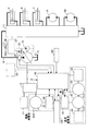
図2は、本発明の実施形態によるハイブリッド式ショベルの駆動系の構成を示すブロック図である。図2において、機械的動力系は二重線、高圧油圧ラインは太実線、パイロットラインは破線、電気駆動・制御系は細実線でそれぞれ示されている。 FIG. 2 is a block diagram showing the configuration of the drive system of the hybrid excavator according to the embodiment of the present invention. In FIG. 2, the mechanical power system is indicated by a double line, the high-pressure hydraulic line is indicated by a thick solid line, the pilot line is indicated by a broken line, and the electric drive / control system is indicated by a thin solid line.
機械式駆動部としてのエンジン11と、アシスト駆動部としての電動発電機12は、変速機13の2つの入力軸にそれぞれ接続されている。変速機13の出力軸には、可変容量型油圧ポンプとしてのメインポンプ14と、固定容量型油圧ポンプとしてのパイロットポンプ15が接続されている。メインポンプ14には、高圧油圧ライン16を介してコントロールバルブ17が接続されている。
An
コントロールバルブ17は、ハイブリッド式ショベルにおける油圧系の制御を行う制御装置である。下部走行体1用の油圧モータ1A(右用)及び1B(左用)、ブームシリンダ7、アームシリンダ8、及びバケットシリンダ9等の油圧アクチュエータは、高圧油圧ラインを介してコントロールバルブ17に接続される。なお、油圧系は、下部走行体1用の油圧モータ1A(右用)及び1B(左用)、ブームシリンダ7、アームシリンダ8、バケットシリンダ9、メインポンプ14、コントロールバルブ17を含む。
The
電動発電機12には、電動発電機制御部としてのインバータ18を介して、蓄電器としてのキャパシタを含む蓄電系120が接続される。また、蓄電系120には、電動発電機制御部としてのインバータ20を介して電動作業要素としての旋回用電動機21が接続される。旋回用電動機21の回転軸21Aには、レゾルバ22、メカニカルブレーキ23、及び旋回変速機24が接続される。また、パイロットポンプ15には、パイロットライン25を介して操作装置26が接続される。旋回用電動機21と、インバータ20と、レゾルバ22と、メカニカルブレーキ23と、旋回変速機24とで負荷駆動系としての電動旋回系が構成される。
A
操作装置26は、レバー26A、レバー26B、ペダル26Cを含む。レバー26A、レバー26B、及びペダル26Cは、油圧ライン27及び28を介して、コントロールバルブ17及び圧力センサ29にそれぞれ接続される。圧力センサ29は、電気系の駆動制御を行うコントローラ30に接続されている。
The
傾斜センサM1は、ハイブリッド式ショベルが傾斜地に位置することを検出する傾斜地検出部の一例である。本実施例では、傾斜センサM1は、上部旋回体3に搭載される加速度センサであり、上部旋回体3の傾斜角を検出してコントローラ30にその検出値を出力する。
The inclination sensor M1 is an example of an inclined ground detection unit that detects that the hybrid excavator is located on an inclined ground. In the present embodiment, the tilt sensor M1 is an acceleration sensor mounted on the
熱消費部40は、旋回停止時に旋回用電動機21が生成する回生電力を熱として消費するための機能要素である。本実施例では、熱消費部40は、電気抵抗部40a及び流量制御弁40bを含む。なお、電気抵抗部40a及び流量制御弁40bの一方は省略されてもよい。
The
電気抵抗部40aは、切り替えスイッチ及び電気抵抗を含む。切り替えスイッチは、コントローラ30からの制御信号に応じてインバータ20と電気抵抗との間の導通・遮断を切り替えるスイッチである。そして、電気抵抗部40aは、コントローラ30からの制御信号に応じてインバータ20と電気抵抗とを導通させ、旋回停止時に旋回用電動機21が生成する回生電力を直流電力として電気抵抗に受け入れる。電気抵抗は、回生電力を受け入れて熱を発生させる。このように、電気抵抗部40aは、回生電力を熱として消費できるようにすることで、旋回用電動機21が生成する回生電力を確実に消費できるようにする。
The
流量制御弁40bは、メインポンプ14が吐出する作動油の流量を制御可能な弁である。流量制御弁40bは、コントローラ30からの制御信号に応じてメインポンプ14が吐出する作動油の流量を制限してメインポンプ14の吐出圧ひいては吸収馬力を増大させる。流量制御弁40bは、メインポンプ14が吐出する作動油の流量を制限することで圧力損失を生じさせて熱を発生させる。また、メインポンプ14の吸収馬力の増大は、エンジン11の油圧負荷の増大をもたらし、エンジン11が受け入れ可能な電動発電機12によるアシストトルクの増大をもたらす。そして、エンジン11が受け入れ可能なアシストトルクの増大は、電動発電機12が消費可能な回生電力量の増大をもたらし、ひいては、旋回用電動機21が生成可能な回生電力量の増大をもたらす。このように、流量制御弁40bは、回生電力を間接的に熱として消費できるようにすることで、旋回用電動機21が生成する回生電力を確実に消費できるようにする。一方で、エンジン11の目標回転数を低い状態に維持するようにしてもよい。エンジン11の運動エネルギを低い状態に維持することで受け入れ可能な回生電力は増加する。
The flow
図3は蓄電系120の構成を示すブロック図である。蓄電系120は、第1の蓄電器としてのキャパシタ19と、昇降圧コンバータ100と、バスラインとしてのDCバス110とを含む。第2の蓄電器としてのDCバス110は、第1の蓄電器としてのキャパシタ19、電動発電機12、及び旋回用電動機21の間での電力の授受を制御する。キャパシタ19には、キャパシタ電圧値を検出するためのキャパシタ電圧検出部112と、キャパシタ電流値を検出するためのキャパシタ電流検出部113が設けられている。キャパシタ電圧検出部112とキャパシタ電流検出部113によって検出されるキャパシタ電圧値とキャパシタ電流値は、コントローラ30に供給される。
FIG. 3 is a block diagram showing the configuration of the
また、キャパシタ19には、キャパシタ19の温度を検出するための温度検出部としての温度センサM2が設けられている。また、昇降圧コンバータ100にも、昇降圧コンバータ100の温度を検出するための温度検出部としての温度センサM3が設けられている。なお、温度センサM2及び温度センサM3は、例えばサーミスタで構成され、各検出値をコントローラ30に対して出力する。また、キャパシタ19の温度は、キャパシタ19の冷却に用いられる冷却水の温度を検出することで間接的に検出されてもよい。
Further, the
昇降圧コンバータ100は、電動発電機12及び旋回用電動機21の運転状態に応じて、DCバス電圧値が一定の範囲内に収まるように昇圧動作と降圧動作を切り替える制御を行う。DCバス110は、インバータ18及び20と昇降圧コンバータ100との間に配設されており、キャパシタ19、電動発電機12、及び旋回用電動機21の間での電力の授受を行う。
The step-up / step-down
また、キャパシタ19と昇降圧コンバータ100との間には切り替えスイッチM4が設けられている。切り替えスイッチM4は、コントローラ30からの制御信号に応じてキャパシタ19と昇降圧コンバータ100との間の導通・遮断を切り替えるスイッチである。
A changeover switch M4 is provided between the
コントローラ30は、ハイブリッド式ショベルの駆動制御を行う主制御部としての制御装置である。本実施例では、コントローラ30は、CPU及び内部メモリを含む演算処理装置で構成され、CPUが内部メモリに格納された駆動制御用のプログラムを実行することにより各種機能が実現される。
The
また、コントローラ30は、圧力センサ29から供給される信号を速度指令に変換し、旋回用電動機21の駆動制御を行う。圧力センサ29から供給される信号は、旋回機構2を旋回させるために操作装置26を操作した場合の操作量を表す信号に相当する。
Further, the
また、コントローラ30は、電動発電機12の運転制御(電動(アシスト)運転又は発電運転の切り替え)を行うとともに、昇降圧制御部としての昇降圧コンバータ100を駆動制御することによるキャパシタ19の充放電制御を行う。また、コントローラ30は、キャパシタ19の充電状態、電動発電機12の運転状態(アシスト運転又は発電運転)、及び旋回用電動機21の運転状態(力行運転又は回生運転)に基づいて、昇降圧コンバータ100の昇圧動作と降圧動作の切り替え制御を行い、これによりキャパシタ19の充放電制御を行う。
The
この昇降圧コンバータ100の昇圧動作と降圧動作の切り替え制御は、DCバス電圧検出部111によって検出されるDCバス電圧値、キャパシタ電圧検出部112によって検出されるキャパシタ電圧値、及びキャパシタ電流検出部113によって検出されるキャパシタ電流値に基づいて行われる。
The switching control between the step-up / step-down operation of the step-up / down
アシストモータである電動発電機12が発電した電力は、インバータ18を介して蓄電系120のDCバス110に供給された後、昇降圧コンバータ100を介してキャパシタ19に供給され、或いは、インバータ20を介して旋回用電動機21に供給される。また、旋回用電動機21が回生運転して生成した回生電力は、インバータ20を介して蓄電系120のDCバス110に供給された後、昇降圧コンバータ100を介してキャパシタ19に供給され、或いは、インバータ18を介して電動発電機12に供給される。また、キャパシタ19に蓄積された電力は、昇降圧コンバータ100及びDCバス110を介して電動発電機12及び旋回用電動機21の少なくとも一方に供給される。
The electric power generated by the
次に、図4を参照し、蓄電系120で異常が発生した場合に、コントローラ30が蓄電系120を停止させる処理(以下、「蓄電系停止処理」とする。)について説明する。なお、図4は、蓄電系停止処理の流れを示すフローチャートであり、コントローラ30は、所定周期で繰り返しこの蓄電系停止処理を実行する。また、蓄電系120の「異常」は、キャパシタ19における電力の流出入を停止すべき事象が生じた状況の全てを含み得る。
Next, with reference to FIG. 4, a process in which the
最初に、コントローラ30は、蓄電系120が異常であるか否かを判定する(ステップS1)。本実施例では、コントローラ30は、DCバス電圧検出部111、キャパシタ電圧検出部112、キャパシタ電流検出部113、温度センサM2、温度センサM3等の出力に基づいて蓄電系120が異常であるか否かを判定する。具体的には、コントローラ30は、キャパシタ19の温度が所定温度以上となった場合、或いは、昇降圧コンバータ100の温度が所定温度以上となった場合に、蓄電系120が異常であると判定する。また、コントローラ30は、キャパシタ電圧値が所定範囲から逸脱した場合、キャパシタ電流値が所定範囲から逸脱した場合、或いは、DCバス電圧値が所定範囲から逸脱した場合に、蓄電系120が異常であると判定する。また、コントローラ30は、キャパシタ19におけるキャパシタセルの状態を制御・管理するバッテリ・マネジメント・ユニットの故障を検知した場合、或いは、バッテリ・マネジメント・ユニットがキャパシタセルの異常(キャパシタセルの過充電、過放電、キャパシタセルの容量計測結果に基づくキャパシタセルの劣化等)を検知した場合に蓄電系120が異常であると判定してもよい。また、コントローラ30は、DCバス電圧検出部111、キャパシタ電圧検出部112、キャパシタ電流検出部113、温度センサM2、温度センサM3等の異常を検知した場合に蓄電系120が異常であると判定してもよい。また、コントローラ30は、キャパシタ19の内部抵抗の計測結果に基づいてキャパシタ19の劣化を検知した場合に蓄電系120が異常であると判定してもよい。
First, the
蓄電系120が異常であると判定した場合(ステップS1のYES)、コントローラ30は、蓄電系120を停止させる(ステップS2)。本実施例では、コントローラ30は、切り替えスイッチM4に制御信号(遮断信号)を出力してキャパシタ19と昇降圧コンバータ100との間を遮断する。また、コントローラ30は、内部メモリにある蓄電系状態フラグの値を「1」(停止状態)にする。蓄電系状態フラグは、蓄電系120の状態を記憶するフラグであり、初期値として「0」(作動状態)が設定される。そして、コントローラ30は、昇降圧コンバータ100の作動を停止させる。なお、コントローラ30は、昇降圧コンバータ100の作動を停止させるだけで蓄電系120を停止させてもよい。
If it is determined that the
一方、蓄電系120が異常でないと判定した場合(ステップS1のNO)、コントローラ30は、蓄電系120を停止させることなく、今回の蓄電系停止処理を終了させる。また、コントローラ30は、既に蓄電系120を停止させていた場合であっても蓄電系120の作動を再開させることなく今回の蓄電系停止処理を終了させる。
On the other hand, when it is determined that the
但し、コントローラ30は、蓄電系120を停止させた後で蓄電系120が異常でないと判定した場合には、蓄電系120の作動を再開させてもよい(ステップS3)。破線で示すステップS3は、蓄電系120の作動を再開させる処理が省略可能な処理であることを表す。具体的には、コントローラ30は、切り替えスイッチM4に制御信号(導通信号)を出力してキャパシタ19と昇降圧コンバータ100との間を導通させる。また、コントローラ30は、内部メモリにある蓄電系状態フラグの値を「0」(作動状態)にする。そして、コントローラ30は、昇降圧コンバータ100の作動を再開させる。なお、コントローラ30は、昇降圧コンバータ100の作動を停止させるだけで蓄電系120を停止させていた場合には、昇降圧コンバータ100の作動を再開させることで蓄電系120の作動を再開させる。
However, if the
このようにして、コントローラ30は、蓄電系120が異常であると判定した場合に、蓄電系120を停止させる。
In this way, the
次に、図5を参照し、旋回操作が行われた場合に、蓄電系120の状態に応じてコントローラ30が旋回制御の内容を切り替える処理(以下、「旋回制御切り替え処理」とする。)について説明する。なお、図5は、旋回制御切り替え処理の流れを示すフローチャートであり、コントローラ30は、旋回操作が行われた場合にこの旋回制御切り替え処理を実行する。
Next, referring to FIG. 5, when a turning operation is performed, a process in which the
最初に、コントローラ30は、蓄電系120が停止状態にあるか否かを判定する(ステップS11)。本実施例では、コントローラ30は、内部メモリにある蓄電系状態フラグを参照して蓄電系120が停止状態にあるか否かを判定する。
First, the
蓄電系120が停止状態にあると判定した場合(ステップS11のYES)、コントローラ30は、旋回制御の内容として蓄電系停止時旋回制御を採用する(ステップS12)。本実施例では、蓄電系状態フラグの値が「1」(停止状態)の場合、コントローラ30は、蓄電系停止時旋回制御を採用する。なお、蓄電系停止時旋回制御の詳細については後述する。
When it is determined that the
一方、蓄電系120が停止状態にないと判定した場合(ステップS11のNO)、コントローラ30は、旋回制御の内容として通常時旋回制御を採用する(ステップS13)。本実施例では、蓄電系状態フラグの値が「0」(作動状態)の場合、コントローラ30は、通常時旋回制御を採用する。通常時旋回制御では、コントローラ30は、キャパシタ19が所定の充電率(SOC)を維持できるようにキャパシタ19を充放電させる。具体的には、コントローラ30は、キャパシタ19が旋回用電動機21等の各種電気負荷から回生電力を受け入れたとしても、或いは、キャパシタ19の充電以外の目的で電動発電機12が行う発電による発電電力を受け入れたとしても過充電とならないよう、キャパシタ19のSOCを適切なレベル(例えば70%)に維持する。
On the other hand, when it determines with the
なお、本実施例では、キャパシタ19のSOCは、キャパシタ電圧検出部112が検出するキャパシタ電圧値に基づいて算出される。但し、キャパシタ19のSOCは、キャパシタ19の内部抵抗を計測することによって導き出されてもよく、他の任意の公知の方法を用いて導き出されてよい。
In this embodiment, the SOC of the
また、コントローラ30は、蓄電系120が停止状態にあると判定した場合(ステップS11のYES)、ショベルの姿勢が不安定状態にあるか否かを判定し(ステップS14)、その上で、蓄電系停止時旋回制御を採用するか否かを決定してもよい。
When
例えば、コントローラ30は、傾斜センサM1の出力に基づいてショベルが傾斜地に位置することを検出した場合にショベルの姿勢が不安定状態にあると判定する。或いは、レゾルバ22の出力に基づいて算出される旋回速度が所定値以上の場合にショベルの姿勢が不安定状態にあると判定してもよい。或いは、ブーム角度、アーム角度、及びバケット角度から算出されるショベルの作業半径(旋回中心とバケット6との距離)が所定値以上の場合にショベルの姿勢が不安定状態にあると判定してもよい。或いは、ブームシリンダ圧から算出されるバケット6内の土砂等の重量が所定値以上の場合にショベルの姿勢が不安定状態にあると判定してもよい。なお、ブーム角度、アーム角度、バケット角度、ブームシリンダ圧等は公知のセンサを用いて検出される。
For example, the
ショベルの姿勢が不安定状態にあると判定した場合(ステップS14のYES)、コントローラ30は、蓄電系停止時旋回制御を採用する(ステップS12)。
When it is determined that the shovel is in an unstable state (YES in step S14), the
一方、ショベルの姿勢が不安定状態にないと判定した場合(ステップS14のNO)、コントローラ30は、上部旋回体3の旋回を停止させる(ステップS15)。具体的には、コントローラ30は、旋回中であれば、旋回操作が行われている場合であってもメカニカルブレーキ23を作動させて上部旋回体3の旋回を停止させる。或いは、コントローラ30は、旋回中でなければ、旋回操作が行われた場合であっても電動発電機12及び旋回用電動機21を動作させず、上部旋回体3の旋回を開始させないようにする。また、コントローラ30は、エンジン11を停止させてショベルを完全に停止させてもよい。
On the other hand, if it is determined that the shovel is not in an unstable state (NO in step S14), the
なお、破線で示すステップS14及びステップS15は、ショベルの姿勢が不安定状態にあるか否かを判定する処理、及び、旋回を停止させる処理が省略可能な処理であることを表す。 Steps S14 and S15 indicated by broken lines indicate that the process for determining whether or not the shovel is in an unstable state and the process for stopping the turn can be omitted.
このようにして、コントローラ30は、蓄電系120の状態に応じて旋回制御の内容を切り替える。
In this way, the
次に蓄電系停止時旋回制御の詳細について説明する。蓄電系停止時旋回制御において旋回用電動機21が力行運転状態のとき、コントローラ30は、エンジン11の駆動力を利用して電動発電機12を発電機として機能させる。そして、電動発電機12が発電する電力のみで旋回用電動機21を駆動させる。
Next, the details of the turning control when the power storage system is stopped will be described. When the turning
なお、コントローラ30は、旋回速度が所定値を超えないよう速度指令、旋回トルク等(以下、「旋回トルク等」とする。)を制限してもよい。その後の旋回回生時に旋回用電動機21が生成する回生電力の最大値が、電動発電機12の消費可能電力を上回らないようにするためである。なお、消費可能電力は、エンジン11をアシストする電動機として機能する電動発電機12が受け入れ可能な電力であり、エンジン11の負荷が大きい程大きい。例えば、油圧アクチュエータが操作されている場合にはエンジン11の油圧負荷が大きいため、消費可能電力は大きくなる。
The
旋回トルク等を制限すると、上部旋回体3の最大旋回速度は低下する。このとき、油圧アクチュエータの操作が行われている場合、コントローラ30は、最大旋回速度の低下に応じて油圧アクチュエータの動作速度を低下させてもよい。操作者が望む操作感に合わせるためである。具体的には、コントローラ30は、最大旋回速度の低下に応じ、メインポンプ14の斜板傾転角を調整するレギュレータ(図示せず。)を制御してメインポンプ14の吐出量を低減させる。
When the turning torque or the like is limited, the maximum turning speed of the
次に、図6を参照し、蓄電系停止時旋回制御において、旋回用電動機21が回生運転状態の場合にコントローラ30が旋回用電動機21の回生電力を制御する処理について説明する。なお、図6は、その処理の流れを示すフローチャートであり、コントローラ30は、旋回用電動機21が回生運転状態の場合に、所定の制御周期で繰り返しこの処理を実行する。
Next, a process in which the
概略的には、コントローラ30は、蓄電系120を停止させた場合に旋回用電動機21を回生運転させるときにはショベルの姿勢に応じて制動トルクを制限する。旋回中の上部旋回体3を停止させたときに生じる上部旋回体3の慣性による反動によって不安定な状態にあるショベルがバランスを崩してしまうのを防止するためである。なお、制動トルクは、基本的に旋回用電動機21が回生運転によって発生させる制動トルクであるが、メカニカルブレーキ23による制動トルクを含んでいてもよい。
Schematically, the
最初に、コントローラ30は、旋回用電動機21が生成する回生電力を電動発電機12で消費させる(ステップS61)。例えば、エンジン11がアシスト出力を必要としているか否かにかかわらず、電動発電機12を強制的に電動機として機能させる。
First, the
また、コントローラ30は、ショベルの姿勢が不安定状態にある場合には回生電力を制限する(ステップS62)。例えば、コントローラ30は、旋回用電動機21の励磁電流を抑制して旋回用電動機21が生成する回生電力を小さくする。この場合、コントローラ30は回生電力の低減に応じて電動発電機12のアシスト出力を低減させる。旋回用電動機21が発生させる制動トルクを所定の制動トルク未満に制限し、旋回中の上部旋回体3を停止させたときに生じる上部旋回体3の慣性による反動が過度に大きくなるのを防止するためである。また、メカニカルブレーキ23を併用する場合、コントローラ30は、メカニカルブレーキ23を断続的に作動させることによってメカニカルブレーキ23が発生させる制動トルクを制限してもよい。
Further, the
なお、コントローラ30は、旋回用電動機21の回生電力が、電動発電機12の消費可能電力を上回る場合、その超過分を熱として消費させてもよい。具体的には、コントローラ30は、インバータ20を流れる電流を検出する電流検出部(図示せず。)の出力に基づいて回生電力が消費可能電力を上回るか否かを判定する(ステップS63)。そして、回生電力が消費可能電力を上回ると判定した場合(ステップS63のYES)、コントローラ30は、熱消費部40を作動させてその超過分を熱として消費させる(ステップS64)。旋回用電動機21が生成する回生電力の全てを確実に消費させて所望の制動力を発生させるためである。
When the regenerative power of the turning
なお、破線で示すステップS63及びステップS64は、回生電力が消費可能電力を上回るか否かを判定する処理、及び、超過分を熱として消費させる処理が省略可能な処理であることを表す。旋回力行時に旋回トルク等を制限して旋回動作を制限することで、旋回回生時に回生電力が消費可能電力を上回るのを防止できるためである。 Steps S63 and S64 indicated by broken lines indicate that the process for determining whether or not the regenerative power exceeds the consumable power and the process for consuming the excess as heat can be omitted. This is because it is possible to prevent the regenerative power from exceeding the power that can be consumed during regenerative turning by limiting the turning torque and the like during turning power running.
以上の構成により、コントローラ30は、蓄電系120を停止させた場合、旋回用電動機21を力行運転させるときには、発電機として機能する電動発電機12の発電電力を旋回用電動機21に供給する。また、蓄電系120を停止させた場合、旋回用電動機21を回生運転させるときには、旋回用電動機21の回生電力を電動機として機能する電動発電機12に供給する。そのため、蓄電系120を停止させた場合であっても電動旋回系を適切に駆動できる。その結果、不安定な姿勢のショベルで蓄電系120の異常が発生して電動旋回系を停止させたときであっても、その後の電動旋回系の駆動を許可することでショベルを安定姿勢に移行させることができる。
With the above configuration, when the
また、本発明の実施例に係るショベルは、旋回用電動機21の回生電力を熱として消費する熱消費部40を有していてもよい。この場合、回生電力が電動発電機12の消費可能電力より大きい場合であっても回生電力の全てを確実に消費でき、上部旋回体3を所望の制動トルクで停止させることができる。
Moreover, the shovel according to the embodiment of the present invention may include the
また、コントローラ30は、蓄電系120を停止させた場合、旋回用電動機21を力行運転させるときの旋回トルク等を制限することで、その後に旋回用電動機21を回生運転させるときに旋回用電動機21が生成する回生電力を制限してもよい。この場合、回生電力が電動発電機12の消費可能電力より大きくなるのを防止でき、回生電力の全てを電動発電機12で確実に消費できるようにし、上部旋回体3を所望の制動トルクで停止させることができる。
In addition, when the
また、コントローラ30は、蓄電系120を停止させた場合であって、旋回操作と油圧アクチュエータの操作とを含む複合操作が行われた場合、旋回用電動機21を力行運転させるときの旋回トルク等の制限に応じて油圧アクチュエータの動きを制限してもよい。この場合、最大旋回速度の低下に合わせて油圧アクチュエータの動作速度を低下させることができ、操作者が望む操作感を実現できる。
Further, the
また、コントローラ30は、蓄電系120を停止させた場合に旋回用電動機21を回生運転させるとき、ショベルの姿勢が不安定状態にある場合には、制動トルクを制限してもよい。この場合、旋回中の上部旋回体3を停止させたときに生じる上部旋回体3の慣性による反動によってショベルがバランスを崩してしまうのを防止できる。
Further, the
以上、本発明の好ましい実施例について詳説したが、本発明は、上述した実施例に制限されることはなく、本発明の範囲を逸脱することなしに上述した実施例に種々の変形及び置換を加えることができる。 Although the preferred embodiments of the present invention have been described in detail above, the present invention is not limited to the above-described embodiments, and various modifications and substitutions can be made to the above-described embodiments without departing from the scope of the present invention. Can be added.
また、本願は、2014年3月31日に出願した日本国特許出願2014−074521号に基づく優先権を主張するものであり、これらの日本国特許出願の全内容を本願に参照により援用する。 Moreover, this application claims the priority based on the Japan patent application 2014-074521 for which it applied on March 31, 2014, and uses all the content of these Japan patent applications for this application by reference.
1・・・下部走行体 1A、1B・・・油圧モータ 2・・・旋回機構 3・・・上部旋回体 4・・・ブーム 5・・・アーム 6・・・バケット 7・・・ブームシリンダ 8・・・アームシリンダ 9・・・バケットシリンダ 10・・・キャビン 11・・・エンジン 12・・・電動発電機 13・・・変速機 14・・・メインポンプ 15・・・パイロットポンプ 16・・・高圧油圧ライン 17・・・コントロールバルブ 18、20・・・インバータ 19・・・キャパシタ 21・・・旋回用電動機 22・・・レゾルバ 23・・・メカニカルブレーキ 24・・・旋回変速機 25・・・パイロットライン 26・・・操作装置 26A、26B・・・レバー 26C・・・ペダル 27・・・油圧ライン 28・・・油圧ライン 29・・・圧力センサ 30・・・コントローラ 40・・・熱消費部 40a・・・電気抵抗部 40b・・・流量制御弁 100・・・昇降圧コンバータ 110・・・DCバス 111・・・DCバス電圧検出部 112・・・キャパシタ電圧検出部 113・・・キャパシタ電流検出部 120・・・蓄電系 M1・・・傾斜センサ M2・・・温度センサ M3・・・温度センサ M4・・・切り替えスイッチ
DESCRIPTION OF
Claims (7)
前記油圧ポンプを駆動可能な電動発電機と、
蓄電系と、
旋回用電動機と、
制御装置と、を有するショベルであって、
前記制御装置は、当該ショベルの作動中に前記蓄電系が、前記蓄電系と他の系との間での電力の流出入を制限される制限状態である場合、前記旋回用電動機が減速中に発生させる電力を前記電動発電機に供給し、
前記蓄電系が前記制限状態である場合、前記制限状態に移行する前と比べ、前記旋回用電動機による旋回の動きを遅くし、かつ、前記油圧ポンプにより駆動される油圧アクチュエータの動きを遅くする、
ショベル。 A hydraulic pump;
A motor generator capable of driving the hydraulic pump;
A power storage system;
An electric motor for turning;
A shovel having a control device,
When the power storage system is in a restricted state in which the flow of power between the power storage system and another system is restricted during operation of the excavator, the control motor is decelerating. Supplying electric power to be generated to the motor generator ;
When the power storage system is in the restricted state, compared to before the transition to the restricted state, the turning motion by the turning electric motor is slowed down, and the movement of the hydraulic actuator driven by the hydraulic pump is slowed down,
Excavator .
請求項1に記載のショベル。 The storage system is in a state where the storage system is charged when an abnormality including overdischarge, overcharge, deterioration, voltage abnormality, or temperature abnormality occurs in the storage system. Including a state in which the power storage system and the turning electric motor are electrically interrupted by a switch,
The excavator according to claim 1.
前記油圧ポンプを駆動可能な電動発電機と、
蓄電系と、
旋回用電動機と、
制御装置と、を有するショベルであって、
前記制御装置は、当該ショベルの作動中に前記蓄電系が、前記蓄電系と他の系との間での電力の流出入を制限される制限状態である場合、前記旋回用電動機が減速中に発生させる電力を前記電動発電機に供給し、
前記制御装置は、前記ショベルが傾斜地に位置すること、旋回速度が所定値以上であること、アタッチメントの先端が前記ショベルから所定距離だけ離れていること、または、前記アタッチメントの先端に所定の重量がかかっていること、或いは、前記ショベルが不安定な姿勢であること、を含む不安定状態にあるか否かを判定し、
前記不安定状態にある場合、且つ、前記蓄電系が前記制限状態である場合に前記旋回用電動機が減速中に発生させる電力を前記電動発電機に供給させる、
ショベル。 A hydraulic pump;
A motor generator capable of driving the hydraulic pump;
A power storage system;
An electric motor for turning;
A shovel having a control device,
When the power storage system is in a restricted state in which the flow of power between the power storage system and another system is restricted during operation of the excavator, the control motor is decelerating. Supplying electric power to be generated to the motor generator;
The control device is configured such that the excavator is positioned on an inclined ground, the turning speed is a predetermined value or more, the tip of the attachment is separated from the excavator by a predetermined distance, or a predetermined weight is applied to the tip of the attachment. Determining whether or not the excavator is in an unstable state including being in an unstable posture,
When the unstable state and when the power storage system is in the restricted state, the electric power generated by the turning motor during deceleration is supplied to the motor generator .
Shi Yoberu.
前記油圧ポンプを駆動可能な電動発電機と、
蓄電系と、
旋回用電動機と、
制御装置と、を有するショベルであって、
前記制御装置は、当該ショベルの作動中に前記蓄電系が、前記蓄電系と他の系との間での電力の流出入を制限される制限状態である場合、前記旋回用電動機が減速中に発生させる電力を前記電動発電機に供給し、
前記旋回用電動機により旋回駆動される旋回体を有し、
前記制御装置は、前記蓄電系が前記制限状態である場合、前記ショベルの姿勢に応じて前記旋回体に加える制動トルクを低下させる、
ショベル。 A hydraulic pump;
A motor generator capable of driving the hydraulic pump;
A power storage system;
An electric motor for turning;
A shovel having a control device,
When the power storage system is in a restricted state in which the flow of power between the power storage system and another system is restricted during operation of the excavator, the control motor is decelerating. Supplying electric power to be generated to the motor generator;
A swivel body that is swiveled by the swivel motor;
When the power storage system is in the restricted state, the control device reduces a braking torque to be applied to the revolving body according to an attitude of the shovel .
Shi Yoberu.
前記油圧ポンプを駆動可能な電動発電機と、
蓄電系と、
旋回用電動機と、
制御装置と、を有するショベルであって、
前記制御装置は、当該ショベルの作動中に前記蓄電系が、前記蓄電系と他の系との間での電力の流出入を制限される制限状態である場合、前記旋回用電動機が減速中に発生させる電力を前記電動発電機に供給し、
前記蓄電系が制限状態になり、前記旋回用電動機が減速中に発生させる電力を前記電動発電機に供給するとき、前記油圧ポンプを回転させるために必要な力を大きくする、
ショベル。 A hydraulic pump;
A motor generator capable of driving the hydraulic pump;
A power storage system;
An electric motor for turning;
A shovel having a control device,
When the power storage system is in a restricted state in which the flow of power between the power storage system and another system is restricted during operation of the excavator , the control motor is decelerating. Supplying electric power to be generated to the motor generator;
When the power storage system is in a restricted state and the electric power generated by the turning electric motor during deceleration is supplied to the motor generator, the force required to rotate the hydraulic pump is increased .
Shi Yoberu.
請求項5に記載のショベル。 The control device restricts the flow rate of the hydraulic oil discharged from the hydraulic pump with a flow rate control valve, or lowers the engine speed.
The excavator according to claim 5 .
前記油圧ポンプを駆動可能な電動発電機と、
蓄電系と、
旋回用電動機と、
制御装置と、を有するショベルであって、
前記制御装置は、当該ショベルの作動中に前記蓄電系が、前記蓄電系と他の系との間での電力の流出入を制限される制限状態である場合、前記旋回用電動機が減速中に発生させる電力を前記電動発電機に供給し、
当該ショベルの作動中に前記蓄電系が、前記蓄電系と他の系との間での電力の流出入を停止される停止状態の場合、前記ショベルの姿勢に応じて旋回体の旋回を停止させるか蓄電系停止時旋回制御を採用するかを決定する、
ショベル。 A hydraulic pump;
A motor generator capable of driving the hydraulic pump;
A power storage system;
An electric motor for turning;
A shovel having a control device,
When the power storage system is in a restricted state in which the flow of power between the power storage system and another system is restricted during operation of the excavator , the control motor is decelerating. Supplying electric power to be generated to the motor generator;
When the power storage system is in a stopped state in which the flow of power between the power storage system and another system is stopped during operation of the shovel, the swiveling body stops turning according to the position of the shovel. Decide whether to adopt the turning control when power storage system is stopped ,
Shi Yoberu.
Applications Claiming Priority (3)
| Application Number | Priority Date | Filing Date | Title |
|---|---|---|---|
| JP2014074521 | 2014-03-31 | ||
| JP2014074521 | 2014-03-31 | ||
| PCT/JP2015/058839 WO2015151917A1 (en) | 2014-03-31 | 2015-03-24 | Shovel |
Related Child Applications (1)
| Application Number | Title | Priority Date | Filing Date |
|---|---|---|---|
| JP2018032058A Division JP6657278B2 (en) | 2014-03-31 | 2018-02-26 | Excavator |
Publications (2)
| Publication Number | Publication Date |
|---|---|
| JPWO2015151917A1 JPWO2015151917A1 (en) | 2017-04-13 |
| JP6466409B2 true JP6466409B2 (en) | 2019-02-06 |
Family
ID=54240244
Family Applications (2)
| Application Number | Title | Priority Date | Filing Date |
|---|---|---|---|
| JP2016511558A Active JP6466409B2 (en) | 2014-03-31 | 2015-03-24 | Excavator |
| JP2018032058A Active JP6657278B2 (en) | 2014-03-31 | 2018-02-26 | Excavator |
Family Applications After (1)
| Application Number | Title | Priority Date | Filing Date |
|---|---|---|---|
| JP2018032058A Active JP6657278B2 (en) | 2014-03-31 | 2018-02-26 | Excavator |
Country Status (6)
| Country | Link |
|---|---|
| US (1) | US10100493B2 (en) |
| EP (1) | EP3128086B1 (en) |
| JP (2) | JP6466409B2 (en) |
| KR (1) | KR102353042B1 (en) |
| CN (1) | CN105940162B (en) |
| WO (1) | WO2015151917A1 (en) |
Families Citing this family (8)
| Publication number | Priority date | Publication date | Assignee | Title |
|---|---|---|---|---|
| JP6957085B2 (en) * | 2017-01-24 | 2021-11-02 | 住友重機械工業株式会社 | Work machine |
| JP6935122B2 (en) * | 2017-03-06 | 2021-09-15 | 住友重機械工業株式会社 | Work machine |
| CN109555182A (en) * | 2019-01-02 | 2019-04-02 | 湖北金诚信矿业服务有限公司 | A kind of scraper machine control system |
| JP2020117897A (en) * | 2019-01-22 | 2020-08-06 | 住友重機械工業株式会社 | Work machine |
| US11535234B2 (en) * | 2020-02-17 | 2022-12-27 | Deere & Company | Energy management system for a hybrid electric ground vehicle |
| JP2022083136A (en) * | 2020-11-24 | 2022-06-03 | 株式会社エフ・シー・シー | Electric vehicle |
| JP2022139597A (en) * | 2021-03-12 | 2022-09-26 | トヨタ自動車株式会社 | vehicle |
| EP4326946A1 (en) * | 2021-12-22 | 2024-02-28 | Doosan Bobcat North America, Inc. | Systems and methods for control of electrically powered power machines |
Family Cites Families (37)
| Publication number | Priority date | Publication date | Assignee | Title |
|---|---|---|---|---|
| JP3178503B2 (en) * | 1994-07-01 | 2001-06-18 | 株式会社デンソー | Hybrid vehicle control device |
| JP2783983B2 (en) * | 1995-02-03 | 1998-08-06 | 株式会社エクォス・リサーチ | Hybrid vehicle |
| JP3897875B2 (en) * | 1997-10-06 | 2007-03-28 | コベルコ建機株式会社 | Battery operated hydraulic work machine |
| JPH11332007A (en) * | 1998-05-15 | 1999-11-30 | Isuzu Ceramics Res Inst Co Ltd | Driver of series-type hybrid car |
| JP2004190845A (en) * | 2002-12-13 | 2004-07-08 | Shin Caterpillar Mitsubishi Ltd | Drive device for working machine |
| JP4228980B2 (en) * | 2004-04-22 | 2009-02-25 | コベルコ建機株式会社 | Swing drive device for work machine |
| US7596893B2 (en) * | 2005-06-06 | 2009-10-06 | Caterpillar Japan Ltd. | Work machine |
| US7487023B2 (en) * | 2005-10-27 | 2009-02-03 | Kobelco Construction Machinery Co., Ltd. | Construction machine |
| JP4524679B2 (en) * | 2006-03-15 | 2010-08-18 | コベルコ建機株式会社 | Hybrid construction machinery |
| CN101663442B (en) * | 2007-03-23 | 2012-02-29 | 株式会社小松制作所 | Power generation control method of hybrid construction machine and hybrid construction machine |
| US8214110B2 (en) * | 2007-03-29 | 2012-07-03 | Komatsu Ltd. | Construction machine and method of controlling construction machine |
| JP4424370B2 (en) * | 2007-05-02 | 2010-03-03 | ダイキン工業株式会社 | Hydraulic unit and construction machine having the same |
| JP4311478B2 (en) * | 2007-05-30 | 2009-08-12 | ダイキン工業株式会社 | Rotating body drive device |
| CN101918649B (en) * | 2007-12-28 | 2013-02-06 | 住友重机械工业株式会社 | Hybrid construction machine |
| JP5188854B2 (en) * | 2008-03-26 | 2013-04-24 | 住友重機械工業株式会社 | Hybrid construction machine |
| US8798875B2 (en) * | 2008-04-11 | 2014-08-05 | Sumitomo Heavy Industries, Ltd. | Working machine |
| KR101199244B1 (en) * | 2008-06-27 | 2012-11-09 | 스미토모 겐키 가부시키가이샤 | Hybrid construction machine |
| JP4609567B2 (en) * | 2008-10-29 | 2011-01-12 | コベルコ建機株式会社 | Hybrid work machine |
| EP2353956B1 (en) * | 2008-11-10 | 2018-05-09 | Sumitomo Heavy Industries, LTD. | Hybrid construction machine |
| JP5421074B2 (en) * | 2008-11-10 | 2014-02-19 | 住友重機械工業株式会社 | Hybrid construction machine |
| JP5037555B2 (en) | 2009-04-09 | 2012-09-26 | 住友重機械工業株式会社 | Hybrid construction machine |
| JP5149826B2 (en) * | 2009-01-29 | 2013-02-20 | 住友重機械工業株式会社 | Hybrid work machine and servo control system |
| JP2010173599A (en) * | 2009-02-02 | 2010-08-12 | Sumitomo Heavy Ind Ltd | Control method for hybrid type operation machinery, and control method for servo control system |
| KR101361375B1 (en) * | 2009-12-07 | 2014-02-11 | 스미도모쥬기가이고교 가부시키가이샤 | Shovel |
| JP5510116B2 (en) * | 2010-06-25 | 2014-06-04 | 三菱自動車工業株式会社 | Hybrid vehicle regenerative control device |
| JP5363430B2 (en) * | 2010-07-23 | 2013-12-11 | 日立建機株式会社 | Hybrid construction machine |
| US20130157089A1 (en) * | 2010-08-30 | 2013-06-20 | Sumitomo Heavy Industries, Ltd. | Shovel |
| JP5185349B2 (en) * | 2010-10-08 | 2013-04-17 | 日立建機株式会社 | Hybrid construction machine |
| JP5527896B2 (en) * | 2010-12-28 | 2014-06-25 | 日立建機株式会社 | Hybrid work equipment cooling system |
| US8935031B2 (en) * | 2011-01-21 | 2015-01-13 | Hitachi Construction Machinery Co., Ltd. | Construction vehicle control apparatus and construction vehicle |
| JP5747533B2 (en) * | 2011-02-02 | 2015-07-15 | コベルコ建機株式会社 | Swivel work machine |
| JP5509433B2 (en) * | 2011-03-22 | 2014-06-04 | 日立建機株式会社 | Hybrid construction machine and auxiliary control device used therefor |
| JP5647052B2 (en) * | 2011-03-25 | 2014-12-24 | 日立建機株式会社 | Hybrid construction machine |
| WO2012173160A1 (en) | 2011-06-14 | 2012-12-20 | 住友建機株式会社 | Hybrid type working machine and method for controlling same |
| JP5758778B2 (en) * | 2011-11-10 | 2015-08-05 | トヨタ自動車株式会社 | Vehicle and vehicle control method |
| DE112012000318T5 (en) * | 2012-05-23 | 2014-05-08 | Komatsu Ltd. | A hybrid work machine and method for controlling a hybrid work machine |
| CN202831050U (en) * | 2012-09-29 | 2013-03-27 | 张国军 | Hydraulic pump control system for engineering machinery |
-
2015
- 2015-03-24 WO PCT/JP2015/058839 patent/WO2015151917A1/en active Application Filing
- 2015-03-24 EP EP15773193.6A patent/EP3128086B1/en active Active
- 2015-03-24 JP JP2016511558A patent/JP6466409B2/en active Active
- 2015-03-24 CN CN201580006867.0A patent/CN105940162B/en active Active
- 2015-03-24 KR KR1020167020975A patent/KR102353042B1/en active IP Right Grant
-
2016
- 2016-08-04 US US15/228,923 patent/US10100493B2/en active Active
-
2018
- 2018-02-26 JP JP2018032058A patent/JP6657278B2/en active Active
Also Published As
| Publication number | Publication date |
|---|---|
| CN105940162B (en) | 2019-08-16 |
| EP3128086A4 (en) | 2017-12-06 |
| EP3128086A1 (en) | 2017-02-08 |
| US10100493B2 (en) | 2018-10-16 |
| KR102353042B1 (en) | 2022-01-18 |
| JPWO2015151917A1 (en) | 2017-04-13 |
| JP6657278B2 (en) | 2020-03-04 |
| EP3128086B1 (en) | 2020-12-30 |
| WO2015151917A1 (en) | 2015-10-08 |
| US20160340865A1 (en) | 2016-11-24 |
| JP2018087487A (en) | 2018-06-07 |
| CN105940162A (en) | 2016-09-14 |
| KR20160140594A (en) | 2016-12-07 |
Similar Documents
| Publication | Publication Date | Title |
|---|---|---|
| JP6466409B2 (en) | Excavator | |
| EP2573281B1 (en) | Hybrid construction machinery | |
| EP2181905B1 (en) | Hybrid working machine | |
| KR101256483B1 (en) | Hybrid working machine | |
| JP6159681B2 (en) | Hybrid work machine | |
| JPWO2013058325A1 (en) | Hybrid drive hydraulic work machine | |
| JP5274978B2 (en) | Hybrid construction machine | |
| JP6529721B2 (en) | Construction machinery | |
| JP5583901B2 (en) | Hybrid construction machine | |
| KR20130114871A (en) | Electric power system for an excavator | |
| JP4949457B2 (en) | Hybrid construction machine | |
| JP5599767B2 (en) | Swivel control device and excavator | |
| WO2015125601A1 (en) | Construction machine | |
| EP2692953B1 (en) | Shovel | |
| JP2016217087A (en) | Construction machine | |
| JP6169596B2 (en) | Hybrid excavator and control method of hybrid excavator | |
| JP2012251371A (en) | Revolving type work machine |
Legal Events
| Date | Code | Title | Description |
|---|---|---|---|
| A521 | Written amendment |
Free format text: JAPANESE INTERMEDIATE CODE: A523 Effective date: 20170413 |
|
| A131 | Notification of reasons for refusal |
Free format text: JAPANESE INTERMEDIATE CODE: A131 Effective date: 20170815 |
|
| A521 | Written amendment |
Free format text: JAPANESE INTERMEDIATE CODE: A523 Effective date: 20171013 |
|
| A02 | Decision of refusal |
Free format text: JAPANESE INTERMEDIATE CODE: A02 Effective date: 20171205 |
|
| A521 | Written amendment |
Free format text: JAPANESE INTERMEDIATE CODE: A523 Effective date: 20180226 |
|
| A911 | Transfer to examiner for re-examination before appeal (zenchi) |
Free format text: JAPANESE INTERMEDIATE CODE: A911 Effective date: 20180305 |
|
| A912 | Re-examination (zenchi) completed and case transferred to appeal board |
Free format text: JAPANESE INTERMEDIATE CODE: A912 Effective date: 20180511 |
|
| A61 | First payment of annual fees (during grant procedure) |
Free format text: JAPANESE INTERMEDIATE CODE: A61 Effective date: 20190109 |
|
| R150 | Certificate of patent or registration of utility model |
Ref document number: 6466409 Country of ref document: JP Free format text: JAPANESE INTERMEDIATE CODE: R150 |