JP2004190845A - Drive device for working machine - Google Patents
Drive device for working machine Download PDFInfo
- Publication number
- JP2004190845A JP2004190845A JP2002363169A JP2002363169A JP2004190845A JP 2004190845 A JP2004190845 A JP 2004190845A JP 2002363169 A JP2002363169 A JP 2002363169A JP 2002363169 A JP2002363169 A JP 2002363169A JP 2004190845 A JP2004190845 A JP 2004190845A
- Authority
- JP
- Japan
- Prior art keywords
- pump
- motor
- drive circuit
- circuit
- power
- Prior art date
- Legal status (The legal status is an assumption and is not a legal conclusion. Google has not performed a legal analysis and makes no representation as to the accuracy of the status listed.)
- Pending
Links
- 239000012530 fluid Substances 0.000 claims description 75
- 230000006870 function Effects 0.000 claims description 21
- 239000003990 capacitor Substances 0.000 claims description 18
- 238000010248 power generation Methods 0.000 claims description 16
- 230000005540 biological transmission Effects 0.000 claims description 11
- 230000007659 motor function Effects 0.000 claims description 7
- 239000010720 hydraulic oil Substances 0.000 abstract description 39
- 238000010586 diagram Methods 0.000 description 18
- 239000003921 oil Substances 0.000 description 15
- 238000009412 basement excavation Methods 0.000 description 10
- 238000007599 discharging Methods 0.000 description 9
- 230000000694 effects Effects 0.000 description 8
- 239000002131 composite material Substances 0.000 description 6
- 230000009467 reduction Effects 0.000 description 6
- 239000003638 chemical reducing agent Substances 0.000 description 5
- 230000020169 heat generation Effects 0.000 description 4
- 238000010276 construction Methods 0.000 description 3
- 238000009434 installation Methods 0.000 description 3
- 230000008929 regeneration Effects 0.000 description 3
- 238000011069 regeneration method Methods 0.000 description 3
- 230000002457 bidirectional effect Effects 0.000 description 2
- 230000008859 change Effects 0.000 description 2
- 230000007246 mechanism Effects 0.000 description 2
- 230000007935 neutral effect Effects 0.000 description 2
- 230000009471 action Effects 0.000 description 1
- 238000006073 displacement reaction Methods 0.000 description 1
- 238000005265 energy consumption Methods 0.000 description 1
- 239000000446 fuel Substances 0.000 description 1
- 238000004519 manufacturing process Methods 0.000 description 1
- 238000005086 pumping Methods 0.000 description 1
- 230000001172 regenerating effect Effects 0.000 description 1
- 239000007787 solid Substances 0.000 description 1
- 239000013589 supplement Substances 0.000 description 1
Images


Classifications
-
- F—MECHANICAL ENGINEERING; LIGHTING; HEATING; WEAPONS; BLASTING
- F15—FLUID-PRESSURE ACTUATORS; HYDRAULICS OR PNEUMATICS IN GENERAL
- F15B—SYSTEMS ACTING BY MEANS OF FLUIDS IN GENERAL; FLUID-PRESSURE ACTUATORS, e.g. SERVOMOTORS; DETAILS OF FLUID-PRESSURE SYSTEMS, NOT OTHERWISE PROVIDED FOR
- F15B11/00—Servomotor systems without provision for follow-up action; Circuits therefor
- F15B11/16—Servomotor systems without provision for follow-up action; Circuits therefor with two or more servomotors
- F15B11/17—Servomotor systems without provision for follow-up action; Circuits therefor with two or more servomotors using two or more pumps
-
- E—FIXED CONSTRUCTIONS
- E02—HYDRAULIC ENGINEERING; FOUNDATIONS; SOIL SHIFTING
- E02F—DREDGING; SOIL-SHIFTING
- E02F9/00—Component parts of dredgers or soil-shifting machines, not restricted to one of the kinds covered by groups E02F3/00 - E02F7/00
- E02F9/20—Drives; Control devices
- E02F9/2058—Electric or electro-mechanical or mechanical control devices of vehicle sub-units
- E02F9/2062—Control of propulsion units
- E02F9/2075—Control of propulsion units of the hybrid type
-
- E—FIXED CONSTRUCTIONS
- E02—HYDRAULIC ENGINEERING; FOUNDATIONS; SOIL SHIFTING
- E02F—DREDGING; SOIL-SHIFTING
- E02F9/00—Component parts of dredgers or soil-shifting machines, not restricted to one of the kinds covered by groups E02F3/00 - E02F7/00
- E02F9/20—Drives; Control devices
- E02F9/22—Hydraulic or pneumatic drives
- E02F9/2217—Hydraulic or pneumatic drives with energy recovery arrangements, e.g. using accumulators, flywheels
-
- E—FIXED CONSTRUCTIONS
- E02—HYDRAULIC ENGINEERING; FOUNDATIONS; SOIL SHIFTING
- E02F—DREDGING; SOIL-SHIFTING
- E02F9/00—Component parts of dredgers or soil-shifting machines, not restricted to one of the kinds covered by groups E02F3/00 - E02F7/00
- E02F9/20—Drives; Control devices
- E02F9/22—Hydraulic or pneumatic drives
- E02F9/2221—Control of flow rate; Load sensing arrangements
- E02F9/2239—Control of flow rate; Load sensing arrangements using two or more pumps with cross-assistance
- E02F9/2242—Control of flow rate; Load sensing arrangements using two or more pumps with cross-assistance including an electronic controller
-
- F—MECHANICAL ENGINEERING; LIGHTING; HEATING; WEAPONS; BLASTING
- F15—FLUID-PRESSURE ACTUATORS; HYDRAULICS OR PNEUMATICS IN GENERAL
- F15B—SYSTEMS ACTING BY MEANS OF FLUIDS IN GENERAL; FLUID-PRESSURE ACTUATORS, e.g. SERVOMOTORS; DETAILS OF FLUID-PRESSURE SYSTEMS, NOT OTHERWISE PROVIDED FOR
- F15B21/00—Common features of fluid actuator systems; Fluid-pressure actuator systems or details thereof, not covered by any other group of this subclass
- F15B21/14—Energy-recuperation means
-
- F—MECHANICAL ENGINEERING; LIGHTING; HEATING; WEAPONS; BLASTING
- F15—FLUID-PRESSURE ACTUATORS; HYDRAULICS OR PNEUMATICS IN GENERAL
- F15B—SYSTEMS ACTING BY MEANS OF FLUIDS IN GENERAL; FLUID-PRESSURE ACTUATORS, e.g. SERVOMOTORS; DETAILS OF FLUID-PRESSURE SYSTEMS, NOT OTHERWISE PROVIDED FOR
- F15B2211/00—Circuits for servomotor systems
- F15B2211/20—Fluid pressure source, e.g. accumulator or variable axial piston pump
- F15B2211/205—Systems with pumps
- F15B2211/20507—Type of prime mover
- F15B2211/20515—Electric motor
-
- F—MECHANICAL ENGINEERING; LIGHTING; HEATING; WEAPONS; BLASTING
- F15—FLUID-PRESSURE ACTUATORS; HYDRAULICS OR PNEUMATICS IN GENERAL
- F15B—SYSTEMS ACTING BY MEANS OF FLUIDS IN GENERAL; FLUID-PRESSURE ACTUATORS, e.g. SERVOMOTORS; DETAILS OF FLUID-PRESSURE SYSTEMS, NOT OTHERWISE PROVIDED FOR
- F15B2211/00—Circuits for servomotor systems
- F15B2211/20—Fluid pressure source, e.g. accumulator or variable axial piston pump
- F15B2211/205—Systems with pumps
- F15B2211/2053—Type of pump
- F15B2211/20538—Type of pump constant capacity
-
- F—MECHANICAL ENGINEERING; LIGHTING; HEATING; WEAPONS; BLASTING
- F15—FLUID-PRESSURE ACTUATORS; HYDRAULICS OR PNEUMATICS IN GENERAL
- F15B—SYSTEMS ACTING BY MEANS OF FLUIDS IN GENERAL; FLUID-PRESSURE ACTUATORS, e.g. SERVOMOTORS; DETAILS OF FLUID-PRESSURE SYSTEMS, NOT OTHERWISE PROVIDED FOR
- F15B2211/00—Circuits for servomotor systems
- F15B2211/20—Fluid pressure source, e.g. accumulator or variable axial piston pump
- F15B2211/205—Systems with pumps
- F15B2211/2053—Type of pump
- F15B2211/20561—Type of pump reversible
-
- F—MECHANICAL ENGINEERING; LIGHTING; HEATING; WEAPONS; BLASTING
- F15—FLUID-PRESSURE ACTUATORS; HYDRAULICS OR PNEUMATICS IN GENERAL
- F15B—SYSTEMS ACTING BY MEANS OF FLUIDS IN GENERAL; FLUID-PRESSURE ACTUATORS, e.g. SERVOMOTORS; DETAILS OF FLUID-PRESSURE SYSTEMS, NOT OTHERWISE PROVIDED FOR
- F15B2211/00—Circuits for servomotor systems
- F15B2211/20—Fluid pressure source, e.g. accumulator or variable axial piston pump
- F15B2211/205—Systems with pumps
- F15B2211/2053—Type of pump
- F15B2211/20569—Type of pump capable of working as pump and motor
-
- F—MECHANICAL ENGINEERING; LIGHTING; HEATING; WEAPONS; BLASTING
- F15—FLUID-PRESSURE ACTUATORS; HYDRAULICS OR PNEUMATICS IN GENERAL
- F15B—SYSTEMS ACTING BY MEANS OF FLUIDS IN GENERAL; FLUID-PRESSURE ACTUATORS, e.g. SERVOMOTORS; DETAILS OF FLUID-PRESSURE SYSTEMS, NOT OTHERWISE PROVIDED FOR
- F15B2211/00—Circuits for servomotor systems
- F15B2211/20—Fluid pressure source, e.g. accumulator or variable axial piston pump
- F15B2211/205—Systems with pumps
- F15B2211/20576—Systems with pumps with multiple pumps
-
- F—MECHANICAL ENGINEERING; LIGHTING; HEATING; WEAPONS; BLASTING
- F15—FLUID-PRESSURE ACTUATORS; HYDRAULICS OR PNEUMATICS IN GENERAL
- F15B—SYSTEMS ACTING BY MEANS OF FLUIDS IN GENERAL; FLUID-PRESSURE ACTUATORS, e.g. SERVOMOTORS; DETAILS OF FLUID-PRESSURE SYSTEMS, NOT OTHERWISE PROVIDED FOR
- F15B2211/00—Circuits for servomotor systems
- F15B2211/20—Fluid pressure source, e.g. accumulator or variable axial piston pump
- F15B2211/265—Control of multiple pressure sources
- F15B2211/2658—Control of multiple pressure sources by control of the prime movers
-
- F—MECHANICAL ENGINEERING; LIGHTING; HEATING; WEAPONS; BLASTING
- F15—FLUID-PRESSURE ACTUATORS; HYDRAULICS OR PNEUMATICS IN GENERAL
- F15B—SYSTEMS ACTING BY MEANS OF FLUIDS IN GENERAL; FLUID-PRESSURE ACTUATORS, e.g. SERVOMOTORS; DETAILS OF FLUID-PRESSURE SYSTEMS, NOT OTHERWISE PROVIDED FOR
- F15B2211/00—Circuits for servomotor systems
- F15B2211/30—Directional control
- F15B2211/315—Directional control characterised by the connections of the valve or valves in the circuit
-
- F—MECHANICAL ENGINEERING; LIGHTING; HEATING; WEAPONS; BLASTING
- F15—FLUID-PRESSURE ACTUATORS; HYDRAULICS OR PNEUMATICS IN GENERAL
- F15B—SYSTEMS ACTING BY MEANS OF FLUIDS IN GENERAL; FLUID-PRESSURE ACTUATORS, e.g. SERVOMOTORS; DETAILS OF FLUID-PRESSURE SYSTEMS, NOT OTHERWISE PROVIDED FOR
- F15B2211/00—Circuits for servomotor systems
- F15B2211/70—Output members, e.g. hydraulic motors or cylinders or control therefor
- F15B2211/71—Multiple output members, e.g. multiple hydraulic motors or cylinders
- F15B2211/7135—Combinations of output members of different types, e.g. single-acting cylinders with rotary motors
-
- F—MECHANICAL ENGINEERING; LIGHTING; HEATING; WEAPONS; BLASTING
- F15—FLUID-PRESSURE ACTUATORS; HYDRAULICS OR PNEUMATICS IN GENERAL
- F15B—SYSTEMS ACTING BY MEANS OF FLUIDS IN GENERAL; FLUID-PRESSURE ACTUATORS, e.g. SERVOMOTORS; DETAILS OF FLUID-PRESSURE SYSTEMS, NOT OTHERWISE PROVIDED FOR
- F15B2211/00—Circuits for servomotor systems
- F15B2211/70—Output members, e.g. hydraulic motors or cylinders or control therefor
- F15B2211/71—Multiple output members, e.g. multiple hydraulic motors or cylinders
- F15B2211/7142—Multiple output members, e.g. multiple hydraulic motors or cylinders the output members being arranged in multiple groups
Landscapes
- Engineering & Computer Science (AREA)
- General Engineering & Computer Science (AREA)
- Physics & Mathematics (AREA)
- Fluid Mechanics (AREA)
- Mining & Mineral Resources (AREA)
- Civil Engineering (AREA)
- Structural Engineering (AREA)
- Mechanical Engineering (AREA)
- Analytical Chemistry (AREA)
- Chemical & Material Sciences (AREA)
- Fluid-Pressure Circuits (AREA)
- Operation Control Of Excavators (AREA)
- Component Parts Of Construction Machinery (AREA)
- Control Of Multiple Motors (AREA)
Abstract
Description
【0001】
【発明の属する技術分野】
本発明は、エンジンと発電手段を併用した動力源を有する油圧ショベルなどの作業機械の駆動装置に関するものである。
【0002】
【従来の技術】
図9および図10は従来技術に関するものであり、図9は油圧ショべルの構造を示す図、図10はその油圧システムの構成を示す回路図である。
【0003】
図9において、下部走行体1に上部旋回体2が旋回可能に結合され、この上部旋回体2に、上部旋回体2に揺動自在に取付けられブームシリンダ3aで駆動されるブーム3と、ブーム3の先端に揺動自在に取付けられスティックシリンダ4aで駆動されるスティック4と、スティック4の先端に取付けられバケットシリンダ5aで駆動されるバケット5とを備えた作業装置6が搭載されている。
【0004】
図10に示されるように、従来の油圧システムは、上部旋回体2に搭載されたエンジン7と、エンジン7によって駆動される斜板制御装置8a,9aを有する可変容量型の油圧ポンプ8,9と、パイロット圧を供給するためのパイロットポンプ10と、油圧ポンプ8,9の圧油を各アクチュエータに分配するためのパイロット操作式の弁装置11と、弁装置11をパイロット制御するための操作弁(以下、操作弁を「リモコン弁」という)12と、エンジン7の回転速度を設定するエンジン回転設定器13と、エンジン7および油圧ポンプ8,9の出力を制御する制御器14と、作業装置6を駆動するブームシリンダ3a、スティックシリンダ4a、バケットシリンダ5aと、上部旋回体2を旋回させるための油圧モータ15と、下部走行体1を駆動させる走行用の油圧モータ16a,16bとを備えている。
【0005】
図10において、リモコン弁12を操作して弁装置11を切換え、エンジン7によって駆動される油圧ポンプ8,9の圧油を各アクチュエータに分配して作業機を作動させる。
【0006】
このようにエンジン7により油圧ポンプ8,9を直接駆動する駆動システムでは、軽負荷から重負荷までの種々の作業に対応できるように、最大負荷を見込んだ大出力のエンジン7を搭載しているが、重負荷の作業は作業時間全体の一部でしかない。
【0007】
このような大出力のエンジン7を搭載した従来の建設機械では、軽負荷や使用率の大半を占める中負荷の作業を行う場合、弁装置11で油圧ポンプ8,9の吐出圧油を絞って、ブームシリンダ3a、スティックシリンダ4a、バケットシリンダ5aなどの各アクチュエータに分配するため、燃料消費量、騒音、生産コストなどの点で不利である。
【0008】
また、軽負荷の作業は、エンジン出力を絞ったり、エンジン回転速度の低い状態で行うが、エンジン7の特性からエンジン回転速度が低いほど、トルクが小さく、かつ不安定であり、エンストや回転むらが生じ易く、操作性上、好ましくない。
【0009】
これに対して、油圧ショベルの動力源としてエンジンによって発電手段を駆動し、この発電手段から供給される電力をバッテリに蓄え、電力によって単数の電動手段を回転させ、この電動手段によって油圧ポンプを駆動し、この油圧ポンプから供給された作動油を共通の弁装置により制御して、下部走行体の左右走行用油圧モータ、上部旋回体の旋回用油圧モータおよび作業装置のブームシリンダ、アームシリンダ、バケットシリンダなどの各油圧アクチュエータを作動させるものがある(例えば、特許文献1参照)。
【0010】
【特許文献1】
特開2001−11888号公報(第3頁、図2)
【0011】
【発明が解決しようとする課題】
上記公報に記載された油圧ショベルは、図10に示された従来技術との比較では、エンジンをより効率良く運転することも可能であるが、各油圧アクチュエータを駆動する回路がそれぞれ独立しているため、それらの各油圧アクチュエータの駆動回路間で、余剰エネルギが有効に利用されていない。
【0012】
本発明は、このような点に鑑みなされたもので、複数の駆動回路間で余剰エネルギを有効利用できるようにすることで、小型化を図れる作業機械の駆動装置を提供することを目的とするものである。
【0013】
【課題を解決するための手段】
請求項1に記載された発明は、作業装置を複数の流体圧アクチュエータにより作動する作業機械の駆動装置であって、エンジンと、エンジンにより駆動される発電手段と、発電手段により発電された電力を蓄える蓄電手段と、複数の流体圧アクチュエータに対してそれぞれ設けられ発電手段および蓄電手段の少なくとも一方から供給された電力により作動されて発生した作動流体圧により流体圧アクチュエータを駆動する複数の駆動回路と、一の駆動回路から他の駆動回路に作動流体を補充する応援回路とを具備した作業機械の駆動装置であり、応援回路によって、複数の駆動回路間で作動流体が持つ余剰エネルギを有効利用でき、エンジンにより駆動される発電手段や蓄電手段から供給された電力により作動されて作動流体圧を発生する各駆動回路の個々の能力を減少させることができ、各駆動回路を構成する部品の小型化を図れるとともに、コスト低減を図れる。
【0014】
請求項2に記載された発明は、請求項1記載の作業機械の駆動装置における駆動回路が、発電手段および蓄電手段の少なくとも一方から供給された電力により作動する回転速度制御可能の電動手段と、電動手段により駆動されるポンプと、ポンプから吐出された作動流体を方向制御して流体圧アクチュエータに供給する弁装置と、ポンプから流体圧アクチュエータに供給された作動流体を回収してポンプに循環させるタンクとを具備したものであり、回転速度制御可能の電動手段でポンプ流量を制御することで、弁装置が流量制御のために回路を絞ることをなくしたので、弁装置における圧力損失を低減することが可能となり、従来の流量制御をしていた弁装置および配管による絞り損失がなくなり、無駄な発熱を抑えられるなどのエネルギー効率を改善できる。
【0015】
請求項3に記載された発明は、請求項1または2記載の作業機械の駆動装置において、駆動回路は、流体圧アクチュエータに一体に設けられたものであり、流体圧アクチュエータに駆動回路を一体に設けることで、駆動回路の配管ロスを低減できるとともに、駆動回路の機械本体側の設置スペースを省略できる。
【0016】
請求項4に記載された発明は、請求項1乃至3のいずれか記載の作業機械の駆動装置において、複数の駆動回路の少なくとも1つが、閉回路と、閉回路中に設けられ作動流体を供給するポンプ機能と作動流体の供給を受けて作動する流体圧モータ機能とを兼備した両方向吐出型のポンプ・モータと、発電手段および蓄電手段の少なくとも一方から供給された電力により作動してポンプ・モータを駆動する電動機機能とポンプ・モータにより駆動されて発電する発電機機能とを兼備したモータ・ジェネレータとを具備したものであり、電動手段として機能するモータ・ジェネレータにより、閉回路内のポンプ・モータをポンプとして作動させることで、流体圧アクチュエータを作動させることができ、このとき、両方向吐出型のポンプ・モータは、モータ・ジェネレータの回転方向により吐出方向を選択して、流体圧アクチュエータの作動方向を制御でき、また、流体圧アクチュエータが外部負荷によって作動される場合は、流体圧アクチュエータがポンプとして機能することにより、閉回路中に生じた作動流体圧によりポンプ・モータが流体圧モータとして作動するので、このポンプ・モータによりモータ・ジェネレータを発電手段として駆動し、発電された電力を蓄電手段に充電することで、エンジンの負担を軽減でき、余剰エネルギの有効利用を図れる。
【0017】
請求項5に記載された発明は、作業装置を複数の流体圧アクチュエータにより作動する作業機械の駆動装置であって、エンジンと、エンジンに接続された動力伝達装置と、動力伝達装置に接続され電動手段および発電手段として機能するモータ・ジェネレータと、モータ・ジェネレータにより発電された電力を蓄えるとともにモータ・ジェネレータに電力を供給する蓄電手段と、動力伝達装置に接続されエンジンおよびモータ・ジェネレータの少なくとも一方により駆動されるポンプとして機能するとともにモータ・ジェネレータを駆動する流体圧モータとして機能するポンプ・モータと、動力伝達装置に接続されエンジンおよびモータ・ジェネレータの少なくとも一方により駆動されるポンプと、複数の流体圧アクチュエータに対してそれぞれ設けられポンプ・モータおよびポンプの少なくとも一方から吐出された作動流体により流体圧アクチュエータを駆動するとともに流体圧アクチュエータから戻された作動流体をタンクに回収してポンプ・モータおよびポンプの少なくとも一方に循環させる複数の駆動回路と、一の駆動回路から他の駆動回路に作動流体を補充する応援回路とを具備した作業機械の駆動装置であり、エンジンは一定負荷状態で運転し、流体圧アクチュエータが必要とする動力が少ないときは、エンジン動力の余剰分を、モータ・ジェネレータで発電して電気エネルギに変換し、蓄電手段に充電し、一方、流体圧アクチュエータが必要とする動力がエンジンの出力より大きいときは、蓄電手段に充電された電力をモータ・ジェネレータに供給して、このモータ・ジェネレータを電動手段として機能させる。また、応援回路によって、複数の駆動回路間で作動流体が持つ余剰エネルギを有効利用でき、ポンプ・モータおよびポンプの個々の能力を減少させることができ、小型化によるコスト低減を図れるとともに、エンジンおよびモータ・ジェネレータの少なくとも一方により動力伝達装置を介してポンプ・モータおよびポンプの少なくとも一方を駆動するので、ポンプ駆動用の高価な電動手段を削減でき、コスト低減を図れる。
【0018】
請求項6に記載された発明は、請求項1乃至5のいずれか記載の作業機械の駆動装置において、共通の駆動回路に対して複数の流体圧アクチュエータがパラレルに接続されたものであり、流体圧アクチュエータの個数に対して、駆動回路の個数を削減でき、コスト低減を図れる。
【0019】
請求項7に記載された発明は、請求項1乃至6のいずれか記載の作業機械の駆動装置における蓄電手段が、キャパシタと、バッテリとを具備したものであり、キャパシタにより、瞬時の充放電に対応できるとともに、バッテリにより、比較的長い時間の充放電に対応できる。
【0020】
請求項8に記載された発明は、請求項2または5記載の作業機械の駆動装置におけるタンクが、蓄圧器により加圧されたものであり、タンクを蓄圧器により加圧することにより、ポンプの吸込側圧力を上げて、ポンプでのキャビテーションの発生を防止でき、小型のポンプを高速で回転させることも可能となる。
【0021】
請求項9に記載された発明は、請求項1乃至8のいずれか記載の作業機械の駆動装置における流体圧アクチュエータが、油圧ショベルのブームを作動するブームシリンダと、スティックを作動するスティックシリンダと、バケットを作動するバケットシリンダとを備え、駆動回路は、ブームシリンダを駆動する駆動回路と、スティックシリンダを駆動する駆動回路と、バケットシリンダを駆動する駆動回路とを備え、応援回路は、ブームシリンダの駆動回路からスティックシリンダの駆動回路に対して、バケットシリンダの駆動回路からブームシリンダの駆動回路およびスティックシリンダの駆動回路に対して、それぞれ設けられたものであり、油圧ショベルの掘削作業における掘削時は、必要流量の少ないブームシリンダの駆動回路からスティックシリンダの駆動回路に作動流体を補充でき、また、旋回持上時は、必要流量の少ないバケットシリンダの駆動回路から、流量を必要とするブームシリンダの駆動回路に作動流体を補充でき、さらに、旋回持下時は、必要流量の少ないバケットシリンダの駆動回路から、流量を必要とするスティックシリンダの駆動回路に作動流体を補充できる。
【0022】
【発明の実施の形態】
以下、本発明を図1乃至図3に示された第1実施の形態、図4に示された第2実施の形態、図5に示された第3実施の形態、図6および図7に示された第4実施の形態、図8に示された第5実施の形態を参照しながら詳細に説明する。なお、図9に示された油圧ショベルに関する説明は、本発明に関する説明においても利用する。
【0023】
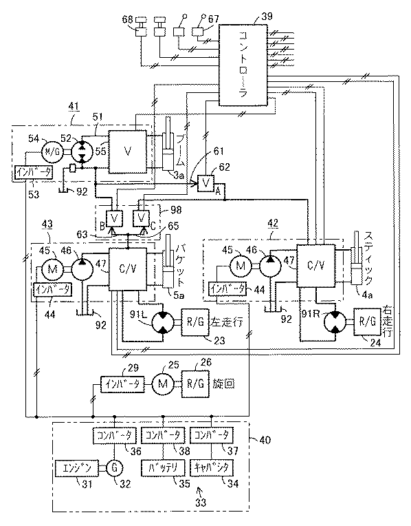
図1は、作業機械の駆動装置の第1実施の形態を示し、作業機械は、図9に示されるようにブーム3、スティック4およびバケット5を順次連結した作業装置6を有する建設機械としての油圧ショベルであり、図1には、この油圧ショベルのブーム・スティック・バケット・複合回路を有する複合ハイブリッド駆動装置の回路図が示され、図2には、図1に示された回路図をさらに具体化した回路図が示されている。
【0024】
図1に示されるように、油圧ショベルの作業装置6を作動する複数のアクチュエータは、加圧された作動流体としての作動油すなわち油圧により作動する流体圧アクチュエータとしての油圧シリンダであり、ブーム作動用のブームシリンダ3aと、スティック作動用のスティックシリンダ4aと、バケット作動用のバケットシリンダ5aとを備えている。
【0025】
一方、油圧ショベルの下部走行体1の左右の履帯を回行作動する左右の走行用アクチュエータは、それぞれ電動機21,22であり、これらの電動機21,22により減速装置23,24を介して左右の履帯がそれぞれ作動される。
【0026】
同様に、下部走行体1に対し上部旋回体2を旋回作動する旋回用アクチュエータは、電動機25であり、この電動機25により減速装置26を介して上部旋回体2が作動される。
【0027】
これらの電動機21,22,25の回転方向および回転速度は、インバータ27,28,29により制御される。
【0028】
また、上部旋回体2には、エンジン31と、このエンジン31により駆動される発電手段としての発電機32と、この発電機32により発電された電力を蓄える蓄電手段33とが、それぞれ搭載されている。
【0029】
蓄電手段33は、瞬時の充放電に対応するキャパシタ34と、比較的長い時間の充放電に対応するバッテリ35とを具備したものである。
【0030】
発電機32には、この発電機32の電圧を制御するためのコンバータ36が接続され、また、キャパシタ34およびバッテリ35には、充放電を制御するためのコンバータ37,38が接続されている。これらのコンバータ36,37,38は、コントローラ39に接続され、このコントローラ39は、負荷に応じて発電機32、キャパシタ34およびバッテリ35の各出力を制御する。
【0031】
エンジン31、発電機32、キャパシタ34、バッテリ35、コンバータ36,37,38により電源ユニット40を構成する。
【0032】
また、ブームシリンダ3aに対して、発電機32および蓄電手段33の少なくとも一方から供給された電力により作動されて発生した作動油圧によりブームシリンダ3aを駆動する駆動回路41が設けられている。
【0033】
同様に、スティックシリンダ4aに対して、発電機32および蓄電手段33の少なくとも一方から供給された電力により作動されて発生した作動油圧によりスティックシリンダ4aを駆動する駆動回路42が設けられている。
【0034】
同様に、バケットシリンダ5aに対して、発電機32および蓄電手段33の少なくとも一方から供給された電力により作動されて発生した作動油圧によりバケットシリンダ5aを駆動する駆動回路43が設けられている。
【0035】
スティックシリンダ4aおよびバケットシリンダ5aの各駆動回路42,43は、それぞれが、発電機32および蓄電手段33の少なくとも一方から供給された電力によりインバータ44で制御された回転速度にて作動される電動手段としての電動機45と、これらの電動機45により駆動されるポンプ46と、これらのポンプ46から吐出された作動油を方向制御してスティックシリンダ4aまたはバケットシリンダ5aに供給する弁装置47と、ポンプ46からスティックシリンダ4aまたはバケットシリンダ5aに供給された作動油を回収してポンプ46に循環させるタンク48とを、それぞれ具備している。
【0036】
一方、ブームシリンダ3aの駆動回路41は、閉回路51と、この閉回路51中に設けられ作動油を供給するポンプ機能と作動油の供給を受けて作動する流体圧モータ機能としての油圧モータ機能とを兼備した両方向吐出型のポンプ・モータ52と、発電機32および蓄電手段33の少なくとも一方から供給された電力によりインバータ53で制御された回転方向および回転速度にて作動されてポンプ・モータ52を駆動する電動機機能とポンプ・モータ52により駆動されて発電する発電機機能とを兼備したモータ・ジェネレータ54とを具備している。
【0037】
閉回路51中には、後述する弁装置55が設けられている。また、閉回路51においては、ブーム下げ時はブームシリンダ3aのロッド側に流入させる作動油流量よりヘッド側から流出させる戻り油流量が多くなり、その余剰分を閉回路51から排出する必要があるので、その余剰分を回収するための、また、ブーム上げ時はポンプ・モータ52の吸込側で作動油流量が不足するので、その不足分を補給するためのタンク56が設けられている。
【0038】
前記走行系の電動機21,22、旋回系の電動機25、スティック系およびバケット系の電動機45およびブーム系のモータ・ジェネレータ54は、交流機を用いても良いし、直流機を用いてもよい。
【0039】
また、一の駆動回路から他の駆動回路に作動流体を補充する応援回路が設けられている。
【0040】
例えば、ブームシリンダ3aの駆動回路41における閉回路51から、スティックシリンダ4aの駆動回路42におけるポンプ吐出側に対して作動油を補充する応援回路61が設けられているとともに、逆方向の応援戻り側回路61rが設けられ、これらの応援回路61および応援戻り側回路61r中には、回路開閉用の応援弁62が設けられている。
【0041】
同様に、バケットシリンダ5aの駆動回路43におけるポンプ吐出側から、ブームシリンダ3aの駆動回路41における閉回路51に対して作動油を補充する応援回路63が設けられているとともに、逆方向の応援戻り側回路63rが設けられ、これらの応援回路63および応援戻り側回路63r中には、回路開閉用の応援弁64が設けられている。
【0042】
同様に、バケットシリンダ5aの駆動回路43におけるポンプ吐出側から、スティックシリンダ4aの駆動回路42におけるポンプ吐出側に対して作動油を補充する応援回路65が設けられているとともに、逆方向の応援戻り側回路65rが設けられ、これらの応援回路65および応援戻り側回路65r中には、回路開閉用の応援弁66が設けられている。
【0043】
そして、応援回路61,63,65により一の駆動回路から他の駆動回路へ供給された応援油量を、応援戻り側回路61r,63r,65rにより回収することで、複数のタンク48,48,56間に作動油量の不均衡が生ずることを防止する。
【0044】
この図1において、前記コントローラ39には、レバー式、ペダル式の電気式操作器67,68が接続され、これらの電気式操作器67,68からコントローラ39に入力された操作信号が、コントローラ39によって演算処理され、その処理後の制御信号が、コントローラ39からインバータ44,53、弁装置47、弁装置55、応援弁62,64,66などに出力される。
【0045】
図2に示されるように、前記タンク48,56は、蓄圧器71により加圧されている。すなわち、これらのタンク48,56は、密閉された圧力容器を用い、圧力容器内に伸縮性を有する隔膜部材72を介して油室73とガス室74とを区画形成し、ガス室74に封入された圧縮ガスの圧力を利用して、ポンプ46またはポンプ・モータ52の吸込口に連通する油室73内の作動油を加圧するアキュムレータ構造である。
【0046】
このような蓄圧器71を設けたのは、電動機45およびポンプ46、またはポンプ・モータ52およびモータ・ジェネレータ54の小型化にともなって、これらの使用回転速度を上げると、ポンプ46またはポンプ・モータ52の吸込側にキャビテーションが発生しやすくなるので、このキャビテーションの発生を防止するために、ポンプ46またはポンプ・モータ52の吸込側の圧力を上げるための蓄圧器71が必要となる。
【0047】
また、スティック系およびバケット系の各ポンプ46からの作動油吐出流量は、電動機45の回転速度により調節する。スティックシリンダ4aまたはバケットシリンダ5aを作動させないときは、各電動機45の回転速度を0rpmとし、各ポンプ46からの作動油吐出流量を0とする。
【0048】
同様に、両方向吐出型のポンプ・モータ52からのポンプ吐出流量は、モータ・ジェネレータ54のモータ回転速度により調節する。さらに、ポンプ・モータ52からのポンプ吐出方向は、モータ・ジェネレータ54のモータ回転方向により制御し、ポンプ吐出方向を変えるときは、モータ・ジェネレータ54のモータ回転方向を変える。
【0049】
また、各応援回路61,63,65の応援弁62,64,66は、前記コントローラ39からのオン/オフ信号をそれぞれのソレノイドに受けて開閉動作する弁であり、オン信号により開動作すると、一の駆動回路から他の駆動回路に作動流体を補充する応援機能が働く。
【0050】
また、スティック系の駆動回路42、およびバケット系の駆動回路43にそれぞれ設けられた弁装置47は、それらの弁本体内に、シリンダ伸縮用の回路を切換えるための方向切換弁76と、この方向切換弁76の作動油供給側に設けられたロードホールドチェック弁77、およびポンプ吐出圧設定用のリリーフ弁78と、方向切換弁76の作動油出力側に設けられた回路圧設定用のリリーフ弁79とを、それぞれ備えている。
【0051】
ここで、方向切換弁76は、通常は、圧力損失を少なくするため全開で使用し、前記コントローラ39からのオン/オフ信号を受けたソレノイドにより、中立位置から一側全開位置または他側全開位置に切換動作するが、応援弁64,66の応援機能が作用したときに、応援先の圧力が高い場合は、方向切換弁76をリニア信号により絞込んで、応援先より高圧となる差圧を発生させるようにする。
【0052】
一方、ブーム系の駆動回路41には、閉回路51のヘッド側通路51a中およびロッド側通路51b中にそれぞれ電磁式の制御弁81,82が設けられ、これらの制御弁81,82よりブームシリンダ3a側には、ヘッド側通路51aおよびロッド側通路51bの設定圧以上の過剰圧をタンク通路83に逃がすためのリリーフ弁84が設けられ、逆に、タンク通路83からヘッド側通路51aおよびロッド側通路51bに油を補充するためのチェック弁85が設けられている。
【0053】
制御弁81,82は、通常は、圧力損失を少なくするためブームシリンダ3aを作動させるとき全開で使用し、前記コントローラ39からのオン信号を受けたソレノイドにより、全閉位置から全開位置に切換動作させるが、応援弁62の応援機能が作用したときに、応援先の圧力が高い場合は、制御弁81,82をリニア信号により絞込んで、応援先より高圧となる差圧を発生させるようにする。
【0054】
また、各制御弁81,82よりポンプ・モータ52側には、ヘッド側通路51aとロッド側通路51bとの間を連通させてブームシリンダ3aのヘッド側からの戻り油の一部をロッド側へ再生する電磁式の再生弁86が設けられ、さらに、ロッド側通路51bからタンク通路83に余剰油を排出するための電磁式の排出弁87およびリリーフ弁88が設けられ、さらに、タンク通路83からヘッド側通路51aおよびロッド側通路51bに油を補給するためのチェック弁89が設けられている。
【0055】
そして、このブーム系の駆動回路41は、ブーム下げ時は、ブームシリンダ3aのロッド側に流入させる作動油流量よりヘッド側から流出させる戻り油流量が多くなり、その余剰分を閉回路51から排出する必要があるので、ブームシリンダ3aのロッド側で必要とされる流量以外の油を、図2に実線矢印で示されように、ロッド側通路51bから排出弁87およびリリーフ弁88を経てタンク56へ戻し、また、ブーム上げ時は、ポンプ・モータ52の吸込側で作動油流量が不足するので、その不足分の作動油を、図2に破線矢印で示されように、タンク56よりタンク通路83およびチェック弁89を経てロッド側通路51bに吸込むことで補給する。
【0056】
次に、ブームシリンダ3a、スティックシリンダ4aおよびバケットシリンダ5aと、これらの各シリンダに対応する各駆動回路41,42,43は、それぞれ一体化されてアクチュエータ駆動ユニットを構成している。
【0057】
例えば、図3は、スティックシリンダ4aと駆動回路42とを一体化したアクチュエータ駆動ユニットの一例を示し、スティックシリンダ4aに、マニホールドプレート90を介して、電動機45、ポンプ46、弁装置47およびタンク48などの駆動回路42が、一体に設けられている。
【0058】
ポンプ46、弁装置47、タンク48およびスティックシリンダ4aは、マニホールドプレート90内に設けられた通路により連通する。
【0059】
なお、駆動回路41,42,43だけでなく応援回路62,64,66も各シリンダに一体化するようにしても良い。
【0060】
次に、この図1乃至図3に示されたブーム・スティック・バケット・複合回路の作用効果を説明する。
【0061】
(1)作動概要
エンジン31は一定負荷状態で運転し、各電動機21,22,25,45およびモータ・ジェネレータ54で消費される総モータ動力がエンジン31の出力より少ないときは、発電機32から出力された電気エネルギをキャパシタ34またはバッテリ35に充電する。
【0062】
一方、各電動機21,22,25,45およびモータ・ジェネレータ54で消費される総モータ動力がエンジン31の出力より多いときは、発電機32から出力される電力に加えて、キャパシタ34またはバッテリ35に蓄えられた電力を、各電動機21,22,25,45およびモータ・ジェネレータ54のモータ動力源として供給する。
【0063】
また、本駆動装置は、各アクチュエータの駆動回路41,42,43を独立駆動の構成とし、ブーム系の駆動回路41からスティック系の駆動回路42へ、またバケット系の駆動回路43からブーム系の駆動回路41およびスティック系の駆動回路42へ作動油流量を補充応援する応援回路61,63,65を設け、流量の補充応援が必要な場合のみ応援弁62,64,66を開とし、応援先に流量を供給する。
【0064】
ブーム系およびスティック系の駆動回路41,42の能力は、これらの必要動力および流量分の略1/2に制限して小型化を図り、能力以上の要求がある場合は、他系統の駆動回路41,43より応援を受けるようにする。
【0065】
すなわち、指令値は電気式操作器67,68からの操作信号であるが、これらの操作量0〜100%に対し、ブーム系およびスティック系の駆動回路41,42は、略50%の能力に制限し、これ以上の操作量があった場合は、他系統の駆動回路41,43より応援を受けることになる。
【0066】
例えば、ダンプ積込作業において、掘削、旋回持上、ダンプ、旋回持下の4つに区分される操作形態がある。ここで、各操作形態の必要平均動力は次の表1のようになる。なお、これは、一例であり、変動は考えられる。100%を最大駆動動力とする。
【0067】
【表1】
この表1に示されるように、
掘削時は、スティック系に動力、スピードが要求され、バケット系にもかなりの動力、スピードが必要となる。一方、ブーム系は、それほどの動力が要らないため、応援弁62を開いて、ブーム系よりスティック系に作動油流量を補充応援する。
【0069】
旋回持上時は、ブーム系に動力、スピードが要求される。一方、スティック系、バケット系には、それほどの動力は要らないため、応援弁64を開いて、バケット系よりブーム系に作動油流量を補充応援する。
【0070】
ダンプ時は、応援不要である。
【0071】
旋回持下時は、ブーム3が自重落下するので、再生弁86を開いて、ブームシリンダ3aを再生作用により駆動できるため、動力は略0となる。このときバケット5はほとんど動かさないため、応援弁66を開いてバケット系よりスティック系に作動油流量を補充応援する。
【0072】
(2)効果
このように、油圧ショベルの掘削作業における掘削時は、必要流量の少ないブームシリンダ3aの駆動回路41から、応援回路61によって、スティックシリンダ4aの駆動回路42に作動油を補充でき、また、旋回持上時は、必要流量の少ないバケットシリンダ5aの駆動回路43から、応援回路63によって、流量を必要とするブームシリンダ3aの駆動回路41に作動油を補充でき、さらに、旋回持下時は、必要流量の少ないバケットシリンダ5aの駆動回路43から、応援回路65によって、流量を必要とするスティックシリンダ4aの駆動回路42に作動流体を補充できる。
【0073】
そして、各駆動回路41,42,43を独立駆動回路とすると、ブームシリンダ3aの駆動回路41、スティックシリンダ4aの駆動回路42には、ほぼ100%の動力、スピードを供給できる能力が要求されるが、応援回路61,63,65を設けることにより、各駆動回路41,42の能力が略1/2で済む。
【0074】
このため、応援回路用の応援弁62,64,66などのコストアップを差引いても、システム全体での低コストを実現できるとともに、駆動回路内機器の小型化を図ることができる。
【0075】
この小型化により、図3に示されるように、スティックシリンダ4aおよびバケットシリンダ5aに、これらに対応する各駆動回路42,43の電動機45、ポンプ46、弁装置47およびタンク48を、それぞれ一体に設置することも可能となり、また、ブームシリンダ3aに、対応する駆動回路41のポンプ・モータ52、モータ・ジェネレータ54、弁装置55およびタンク56を、一体に設置することも可能となる。
【0076】
このように、各流体圧アクチュエータにそれらの駆動回路41,42,43をそれぞれ一体に設けることで、これらの駆動回路41,42,43の配管ロスを低減できるとともに、機械本体側すなわち上部旋回体2上の駆動回路用の設置スペースを省略できる。
【0077】
仮に、100%の動力分の装置ならば、モータ、ポンプなどの各機器のサイズは大型化し、重量も重くなり、各シリンダへの設置は困難になる。
【0078】
要するに、応援回路61,63,65によって、複数の駆動回路41,42,43間で作動油が持つ余剰エネルギを有効利用でき、エンジン31により駆動される発電機32や蓄電手段33から供給された電力により作動されて作動油圧を発生する各駆動回路41,42,43の個々の能力を減少させることができ、各駆動回路41,42,43を構成する部品の小型化を図れるとともに、コスト低減を図れる。
【0079】
次に、コントローラ39によりインバータ44,53を介して電動機45またはモータ・ジェネレータ54の回転速度を制御することにより、ポンプ46またはポンプ・モータ52から吐出されるポンプ流量を制御することができ、これにより、弁装置47,55が流量制御のために回路を絞ることをなくしたので、弁装置47,55における圧力損失を低減することが可能となり、従来の流量制御をしていたコントロール弁および配管による絞り損失がなくなり、無駄な発熱を抑えられるなどのエネルギー効率を改善できる。
【0080】
また、電動手段として機能するモータ・ジェネレータ54により、閉回路51内のポンプ・モータ52をポンプとして作動させることで、ブームシリンダ3aを作動させるときは、モータ・ジェネレータ54の回転方向により、両方向吐出型のポンプ・モータ52の吐出方向を選択して、ブームシリンダ3aの作動方向を制御できる。
【0081】
さらに、ブームシリンダ3aが作業装置6の自重などの外部負荷によって作動される場合は、ブームシリンダ3aがポンプとして機能することにより、閉回路51中に生じた作動油圧によりポンプ・モータ52が油圧モータとして作動するので、このポンプ・モータ52によりモータ・ジェネレータ54を発電機として駆動し、発電された電力を蓄電手段33のキャパシタ34およびバッテリ35に充電することで、エンジン31の負担を軽減でき、余剰エネルギの有効利用を図れる。
【0082】
また、電動機45またはモータ・ジェネレータ54などの電動手段は、交流機または直流機を用いる。例えば、小型化された交流機によって、電動機45またはモータ・ジェネレータ54を油圧シリンダにコンパクトに組込むことができる。これらの電動機45またはモータ・ジェネレータ54は、直流機でも適用可能である。
【0083】
また、蓄電手段33は、キャパシタ34と、バッテリ35とを具備したものであり、キャパシタ34により、瞬時の充放電に対応できるとともに、バッテリ35により、比較的長い時間の充放電に対応でき、高性能の蓄電能力が得られる。
【0084】
また、タンク48,56を蓄圧器71により加圧することにより、ポンプ46またはポンプ・モータ52の吸込側圧力を上げて、ポンプ46またはポンプ・モータ52でのキャビテーションの発生を防止でき、小型のポンプ46またはポンプ・モータ52を高速で回転させることも可能となる。
【0085】
次に、図4は、作業機械の駆動装置の第2実施の形態を示す回路図であり、図1に示された実施の形態と比べると、ブームシリンダ3aの駆動回路41からスティックシリンダ4aの駆動回路42への応援回路61が取り除かれており、バケットシリンダ5aの駆動回路43におけるポンプ吐出側から、ブームシリンダ3aの駆動回路41に作動油を補充する応援回路63と、スティックシリンダ4aの駆動回路42に作動油を補充する応援回路65とが設けられた構成である。なお、図1と同様の部分には、同一符号を付して、その説明を省略する。また、図1に示された応援戻り側回路63r,65rは、図示を省略する。
【0086】
この図4に示された実施の形態は、バケットシリンダ5aの駆動回路43のみからブームシリンダ3aの駆動回路41およびスティックシリンダ4aの駆動回路42に対して作動油を補充することになり、掘削時に、例えばバケット系からスティック系のみに作動油を補充応援する場合は、ブームシリンダ3aおよびバケットシリンダ5aのスピードが少し遅くなるが、掘削作業の作業能率には影響がなく、また、バケット系のみからの応援となるため、回路が簡易化されるとともに、応援弁64,66の制御も容易になる効果がある。
【0087】
次に、図5は、作業機械の駆動装置の第3実施の形態を示す回路図であり、図1に示された実施の形態と比べると、ブームシリンダ3aの駆動回路41からスティックシリンダ4aの駆動回路42への応援回路61が取り除かれているとともに、バケットシリンダ5aの駆動回路43からブームシリンダ3aの駆動回路41への応援回路63が取り除かれており、バケットシリンダ5aの駆動回路43におけるポンプ吐出側からスティックシリンダ4aの駆動回路42に作動油を補充する応援回路65のみが設けられた構成である。なお、図1と同様の部分には、同一符号を付して、その説明を省略する。また、図1に示された応援戻り側回路65rは、図示を省略する。
【0088】
この図5に示された実施の形態は、バケットシリンダ5aの駆動回路43のみからスティックシリンダ4aの駆動回路42のみに対して作動油を補充することになり、この場合は、図4に示された実施の形態より、各シリンダのスピードが少し遅くなるが、スティックシリンダ4aの必要な作動速度は確保できるため、掘削作業の作業能率には影響がなく、また、バケット系のみからスティック系のみへの応援となるため、回路がより簡易化され、応援弁66の制御もより容易になる効果がある。
【0089】
次に、図6は、作業機械の駆動装置の第4実施の形態を示す回路図であり、図1および図2に示された実施の形態と同様の部分には、同一符号を付して、その説明を省略する。
【0090】
この図6に示された駆動装置は、ブーム・スティック・バケット・走行・複合回路の第1例を有する油圧ショベルの複合ハイブリッド駆動装置であり、共通の駆動回路に対して複数の流体圧アクチュエータがパラレルに接続されたものである。
【0091】
すなわち、本駆動装置は、ブームシリンダ3aの駆動回路41と、上部旋回体2を旋回作動する電動機25などの旋回系の駆動回路とを、それぞれ独立駆動回路とし、一方、駆動回路42は、スティックシリンダ4aと、右走行用の流体圧アクチュエータとしての油圧モータである右走行モータ91Rとがパラレルに接続された共用の回路であり、また、駆動回路43は、バケットシリンダ5aと、左走行用の流体圧アクチュエータとしての油圧モータである左走行モータ91Lとがパラレルに接続された共用の回路である。
【0092】
そして、走行時に作業装置6を連動操作する場合、すなわち、左右の走行モータ91L,91Rと、ブームシリンダ3a、スティックシリンダ4aおよびバケットシリンダ5aとを連動操作する場合は、さほど多くなく、また、連動操作する場合でも、その時間は長くないので、本回路構成としても、スティックシリンダ4aと右走行用の右走行モータ91Rとの間の駆動圧力差を保つため、あるいはバケットシリンダ5aと左走行用の左走行モータ91Lとの間の駆動圧力差を保つため、低圧側アクチュエータ用の方向切換弁を絞る必要はあるが、これにより生ずる損失は、連動操作の時間が短いため少なく、効率の大幅な低下は生じない。
【0093】
また、大きな動力を必要とする掘削積込などの作業時には、走行することはないので、上記のような連動操作時の問題は、全く生じない。
【0094】
なお、ブームシリンダ3a、スティックシリンダ4aおよびバケットシリンダ5aの作動は、図1に示されたブーム・スティック・バケット・複合回路と同様であるから、その説明を省略する。
【0095】
このように、共通の駆動回路42,43に対して複数の流体圧アクチュエータがそれぞれパラレルに接続されたので、流体圧アクチュエータの個数に対して、駆動回路の個数を削減でき、コスト低減を図れる。
【0096】
例えば、図1に示された独立駆動回路では、駆動系は6系統必要となるが、図6に示された実施の形態では、左右の走行系をスティック系およびバケット系とそれぞれ共用回路とすることで、4系統に減らすことができ、コストの低減が図れる。
【0097】
また、応援回路61,63,65を設けることにより、ブーム系およびスティック系の各駆動回路41,42の能力が略1/2で済むことになり、図1に示されたものと同様の効果が得られる。
【0098】
次に、図7は、図6に示されたブーム・スティック・バケット・走行・複合回路を有する建設機械の複合ハイブリッド駆動装置を詳細に示した油圧回路図であり、以下、図6に表われなかった部分のみを説明する。なお、図1および図2に示された実施の形態と同様の部分には、同一符号を付して、その説明を省略する。
【0099】
タンク92は、1つを大型化して、上部旋回体2側に分離設置する。これは、後述する走行直進機能を確保するために、駆動回路42,43間で作動油の移動があるためである。このタンク92にも蓄圧器93が設けられ、タンク92を蓄圧器93により加圧することにより、ポンプ46およびポンプ・モータ52の吸込側圧力を上げて、キャビテーションの発生を防止し、小型のポンプ46などの高速回転を可能とすることは、同様である。
【0100】
また、左右走行系を電気回路から油圧回路に変更したことに伴なって、駆動回路42の弁装置47は、共通のポンプ46に対してスティック用の方向切換弁76と右走行用の方向切換弁94Rとがパラレルに接続され、これらの方向切換弁76,94Rを介しスティックシリンダ4aと右走行用の右走行モータ91Rとがパラレルに接続されている。
【0101】
同様に、駆動回路43の弁装置47は、共通のポンプ46に対してバケット用の方向切換弁76と左走行用の方向切換弁94Lとがパラレルに接続され、これらの方向切換弁76,94Lを介しバケットシリンダ5aと左走行用の左走行モータ91Lとがパラレルに接続されている。
【0102】
このように、右走行系の回路とスティック系の回路、左走行系の回路とバケット系の回路は、それぞれ共通のポンプ46に対してパラレルに接続された回路であるから、原則として、方向切換弁76,94Rおよび方向切換弁76,94Lは中立位置から一側全開位置または他側全開位置に切換制御されるが、仮に、これらの回路間に圧力差が生じた場合は、低圧回路側の方向切換弁に絞り差圧を立て、各アクチュエータに要求どおりの流量を供給する。
【0103】
左右両走行系の回路中には、車体の暴走を防止するためのカウンタバランス弁95L,95Rがそれぞれ設けられている。
【0104】
また、一方の駆動回路43には走行直進弁96が設けられ、この走行直進弁96を走行時オンにすると、右側のポンプ46のみから吐出された作動油が左右走行用の方向切換弁94L,94Rに分配されるので、2つのポンプ46からの異なる吐出圧が左右両走行系に作用することを防止して、左右両走行系の回路圧を等しくすることができ、これにより、左右両走行系の走行モータ91L,91Rを同一回転速度に保って、走行直進性を確保できる。
【0105】
さらに、バケット系の方向切換弁76を含む駆動回路43からチェック弁97を介して引出された通路に、切換弁式の応援弁98が設けられている。この応援弁98は、図1および図2に示された実施の形態における2つの応援弁64,66に相当するもので、この応援弁98をB位置に切換えると、バケット系を含む駆動回路43からブーム系の駆動回路41に作動油流量を応援供給でき、また、応援弁98をC位置に切換えると、バケット系を含む駆動回路43からスティック系を含む駆動回路42に作動油流量を応援供給できる。
【0106】
そして、エンジン31は一定負荷状態で運転し、各電動機25,45およびモータ・ジェネレータ54で消費される総モータ動力がエンジン31の出力より少ないときは、発電機32から出力された電気エネルギをキャパシタ34またはバッテリ35に充電し、一方、各電動機25,45およびモータ・ジェネレータ54で消費される総モータ動力がエンジン31の出力より多いときは、発電機32から出力される電力に加えて、キャパシタ34またはバッテリ35に蓄えられた電力を、各電動機25,45およびモータ・ジェネレータ54のモータ動力源として供給することは、図1および図2に示された実施の形態と同様である。
【0107】
次に、図8は、作業機械の駆動装置の第5実施の形態を示す回路図であり、図2および図7に示された実施の形態と同様の部分には、同一符号を付して、その説明を省略する。
【0108】
この図8に示された駆動装置は、ブーム・スティック・バケット・走行・複合回路の第2例を有する油圧ショベルの複合ハイブリッド駆動装置であり、エンジン31の出力軸に、動力伝達装置としての減速機99が接続され、この減速機99に、電動手段および発電手段として機能するモータ・ジェネレータ54が接続され、このモータ・ジェネレータ54により発電された電力を蓄えるとともにモータ・ジェネレータ54にその電力を供給する蓄電手段33が設けられている。
【0109】
さらに、減速機99には、エンジン31およびモータ・ジェネレータ54の少なくとも一方により駆動されるポンプとして機能するとともにモータ・ジェネレータ54を駆動する流体圧モータすなわち油圧モータとして機能するポンプ・モータ52が接続されているとともに、エンジン31およびモータ・ジェネレータ54の少なくとも一方により駆動される複数のポンプ46が接続されている。
【0110】
減速機99には、ポンプ・モータ52が油圧モータとしてモータ・ジェネレータ54を駆動する際にこのポンプ・モータ52をモータ・ジェネレータ54に直結させるとともにエンジン31およびポンプ46から切離すためのクラッチ機構が内蔵され、また、ポンプ・モータ52のみの回転方向を切換えるための機構が内蔵されている。
【0111】
ポンプ・モータ52から吐出されたポンプ流量が、ブームシリンダ3aの駆動回路41に供給され、一方のポンプ46から吐出されたポンプ流量が、スティックシリンダ4aおよび右走行用の右走行モータ91Rの駆動回路42に供給され、他方のポンプ46から吐出されたポンプ流量が、バケットシリンダ5aおよび左走行用の左走行モータ91Lの駆動回路43に供給されることは、図7に示された実施の形態と同様であるが、これらのポンプ46、ポンプ・モータ52が、エンジン31および減速機99とともに、油圧ショベルの上部旋回体2側に搭載されている点は、図7に示された実施の形態と異なる。
【0112】
次に、この図8に示された実施の形態の作用効果を説明する。なお、既に説明した他の実施の形態と同様の構成から生ずる作用効果は、説明を省略する。
【0113】
エンジン31は一定負荷状態で運転し、ブームシリンダ3a、スティックシリンダ4a、バケットシリンダ5a、旋回系の電動機25などのアクチュエータで消費される動力が少ないときは、エンジン動力の余剰分により、モータ・ジェネレータ54を発電手段として機能させ、モータ・ジェネレータ54から出力された電力をキャパシタ34またはバッテリ35に充電する。
【0114】
一方、アクチュエータから要求される動力がエンジン出力より大きいときは、キャパシタ34またはバッテリ35に充電された電力を、モータ・ジェネレータ54のモータ動力源として供給して、このモータ・ジェネレータ54を電動手段として機能させる。
【0115】
また、応援回路61,63,65によって、油圧ショベルの掘削作業における掘削時は、必要流量の少ないブームシリンダ3aの駆動回路41からスティックシリンダ4aの駆動回路42に作動油を補充でき、また、旋回持上時は、必要流量の少ないバケットシリンダ5aの駆動回路43から、流量を必要とするブームシリンダ3aの駆動回路41に作動油を補充でき、さらに、旋回持下時は、必要流量の少ないバケットシリンダ5aの駆動回路43から、流量を必要とするスティックシリンダ4aの駆動回路42に作動油を補充できる。
【0116】
このように、応援回路61,63,65によって、複数の駆動回路41,42,43間で作動油が持つ余剰エネルギを有効利用でき、各駆動回路41,42,43を構成するポンプ・モータ52およびポンプ46などの個々の能力を減少させることができ、これらの小型化と、小型化によるコスト低減とを図れるとともに、この図8に示された回路は、エンジン31およびモータ・ジェネレータ54の少なくとも一方により減速機99を介してポンプ・モータ52およびポンプ46の少なくとも一方を駆動するので、図2または図7の回路に比べて、旋回系の電動機25以外のポンプ駆動用の電動機を廃止でき、油圧機器と比べて高価な電動機の数を削減できることから、この点でもコスト低減を図れる。
【0117】
【発明の効果】
請求項1記載の発明によれば、応援回路によって、複数の駆動回路間で作動流体が持つ余剰エネルギを有効利用でき、エンジンにより駆動される発電手段や蓄電手段から供給された電力により作動されて作動流体圧を発生する各駆動回路の個々の能力を減少させることができ、各駆動回路を構成する部品の小型化を図れるとともに、コスト低減を図れる。
【0118】
請求項2記載の発明によれば、回転速度制御可能の電動手段でポンプ流量を制御することで、弁装置が流量制御のために回路を絞ることをなくしたので、弁装置における圧力損失を低減することが可能となり、従来の流量制御をしていた弁装置および配管による絞り損失がなくなり、無駄な発熱を抑えられるなどのエネルギー効率を改善できる。
【0119】
請求項3記載の発明によれば、流体圧アクチュエータに駆動回路を一体に設けることで、駆動回路の配管ロスを低減できるとともに、駆動回路の機械本体側の設置スペースを省略できる。
【0120】
請求項4記載の発明によれば、電動手段として機能するモータ・ジェネレータにより、閉回路内のポンプ・モータをポンプとして作動させることで、流体圧アクチュエータを作動させることができ、このとき、両方向吐出型のポンプ・モータは、モータ・ジェネレータの回転方向により吐出方向を選択して、流体圧アクチュエータの作動方向を制御でき、また、流体圧アクチュエータが外部負荷によって作動される場合は、流体圧アクチュエータがポンプとして機能することにより、閉回路中に生じた作動流体圧によりポンプ・モータが流体圧モータとして作動するので、このポンプ・モータによりモータ・ジェネレータを発電手段として駆動し、発電された電力を蓄電手段に充電することで、エンジンの負担を軽減でき、余剰エネルギの有効利用を図れる。
【0121】
請求項5記載の発明によれば、エンジンは一定負荷状態で運転し、流体圧アクチュエータが必要とする動力が少ないときは、エンジン動力の余剰分を、モータ・ジェネレータで発電して電気エネルギに変換し、蓄電手段に充電し、一方、流体圧アクチュエータが必要とする動力がエンジンの出力より大きいときは、蓄電手段に充電された電力をモータ・ジェネレータに供給して、このモータ・ジェネレータを電動手段として機能させる。また、応援回路によって、複数の駆動回路間で作動流体が持つ余剰エネルギを有効利用でき、ポンプ・モータおよびポンプの個々の能力を減少させることができ、小型化によるコスト低減を図れるとともに、エンジンおよびモータ・ジェネレータの少なくとも一方により動力伝達装置を介してポンプ・モータおよびポンプの少なくとも一方を駆動するので、ポンプ駆動用の高価な電動手段を削減でき、コスト低減を図れる。
【0122】
請求項6記載の発明によれば、共通の駆動回路に対して複数の流体圧アクチュエータがパラレルに接続されたので、流体圧アクチュエータの個数に対して、駆動回路の個数を削減でき、コスト低減を図れる。
【0123】
請求項7記載の発明によれば、蓄電手段が、キャパシタと、バッテリとを具備したので、キャパシタにより、瞬時の充放電に対応できるとともに、バッテリにより、比較的長い時間の充放電に対応できる。
【0124】
請求項8記載の発明によれば、タンクを蓄圧器により加圧することにより、ポンプの吸込側圧力を上げて、ポンプでのキャビテーションの発生を防止でき、小型のポンプを高速で回転させることも可能となる。
【0125】
請求項9記載の発明によれば、油圧ショベルの掘削作業における掘削時は、必要流量の少ないブームシリンダの駆動回路からスティックシリンダの駆動回路に作動流体を補充でき、また、旋回持上時は、必要流量の少ないバケットシリンダの駆動回路から、流量を必要とするブームシリンダの駆動回路に作動流体を補充でき、さらに、旋回持下時は、必要流量の少ないバケットシリンダの駆動回路から、流量を必要とするスティックシリンダの駆動回路に作動流体を補充できる。
【図面の簡単な説明】
【図1】本発明に係る作業機械の駆動装置の第1実施の形態を示す回路図である。
【図2】同上駆動装置の油圧回路を詳細に示した回路図である。
【図3】同上駆動装置のアクチュエータ駆動ユニットの一例を示す側面図である。
【図4】本発明に係る作業機械の駆動装置の第2実施の形態を示す回路図である。
【図5】本発明に係る作業機械の駆動装置の第3実施の形態を示す回路図である。
【図6】本発明に係る作業機械の駆動装置の第4実施の形態を示す回路図である。
【図7】同上駆動装置の油圧回路を詳細に示した回路図である。
【図8】本発明に係る作業機械の駆動装置の第5実施の形態を示す回路図である。
【図9】油圧ショベルの側面図である。
【図10】従来の油圧ショべルの油圧システム構成を示す回路図である。
【符号の説明】
3 ブーム
3a 流体圧アクチュエータとしてのブームシリンダ
4 スティック
4a 流体圧アクチュエータとしてのスティックシリンダ
5 バケット
5a 流体圧アクチュエータとしてのバケットシリンダ
6 作業装置
31 エンジン
32 発電手段としての発電機
33 蓄電手段
34 キャパシタ
35 バッテリ
41,42,43 駆動回路
45 電動手段としての電動機
46 ポンプ
47 弁装置
48 タンク
51 閉回路
52 ポンプ・モータ
54 モータ・ジェネレータ
56 タンク
61,63,65 応援回路
71 蓄圧器
91L,91R 流体圧アクチュエータとしての左走行モータおよび右走行モータ
92 タンク
93 蓄圧器
99 動力伝達装置としての減速機[0001]
TECHNICAL FIELD OF THE INVENTION
The present invention relates to a drive device for a working machine such as a hydraulic shovel having a power source using both an engine and a power generating means.
[0002]
[Prior art]
9 and 10 relate to the related art, FIG. 9 is a diagram showing a structure of a hydraulic shovel, and FIG. 10 is a circuit diagram showing a configuration of the hydraulic system.
[0003]
In FIG. 9, an
[0004]
As shown in FIG. 10, the conventional hydraulic system includes an
[0005]
In FIG. 10, the
[0006]
As described above, the drive system in which the hydraulic pumps 8 and 9 are directly driven by the
[0007]
In a conventional construction machine equipped with such a high-
[0008]
The light load operation is performed in a state where the engine output is reduced or the engine rotation speed is low. However, due to the characteristics of the
[0009]
On the other hand, the power generation means is driven by the engine as a power source of the hydraulic shovel, the electric power supplied from the power generation means is stored in a battery, and a single electric means is rotated by the electric power, and the hydraulic pump is driven by the electric means. The hydraulic oil supplied from the hydraulic pump is controlled by a common valve device to control the hydraulic motor for left and right traveling of the lower traveling body, the hydraulic motor for pivoting of the upper rotating body, and the boom cylinder, arm cylinder, and bucket of the working device. There is one that operates each hydraulic actuator such as a cylinder (for example, see Patent Document 1).
[0010]
[Patent Document 1]
JP 2001-11888 A (
[0011]
[Problems to be solved by the invention]
The hydraulic excavator described in the above publication can operate the engine more efficiently in comparison with the prior art shown in FIG. 10, but the circuits for driving the respective hydraulic actuators are independent of each other. Therefore, the excess energy is not effectively used between the drive circuits of the hydraulic actuators.
[0012]
SUMMARY OF THE INVENTION The present invention has been made in view of the above circumstances, and an object of the present invention is to provide a drive device for a working machine that can achieve downsizing by enabling excess energy to be effectively used between a plurality of drive circuits. Things.
[0013]
[Means for Solving the Problems]
The invention described in
[0014]
According to a second aspect of the present invention, there is provided a work machine drive device according to the first aspect, wherein the drive circuit is configured to be driven by electric power supplied from at least one of a power generation unit and a power storage unit, and a rotation speed controllable electric unit; A pump driven by electric means, a valve device for controlling the direction of the working fluid discharged from the pump to supply the fluid to the hydraulic actuator, and collecting and circulating the working fluid supplied to the hydraulic actuator from the pump by the pump A tank is provided, and by controlling the pump flow rate by electric means capable of controlling the rotation speed, the valve device does not have to restrict the circuit for the flow rate control, thereby reducing the pressure loss in the valve device. This eliminates the restriction loss caused by the valve device and piping that used to control the flow rate in the past, and reduces energy consumption such as suppressing unnecessary heat generation. It can improve the efficiency.
[0015]
According to a third aspect of the present invention, in the drive device for a work machine according to the first or second aspect, the drive circuit is provided integrally with the hydraulic actuator, and the drive circuit is integrated with the hydraulic actuator. With this arrangement, the piping loss of the drive circuit can be reduced, and the installation space of the drive circuit on the machine body side can be omitted.
[0016]
According to a fourth aspect of the present invention, in the drive device for a work machine according to any one of the first to third aspects, at least one of the plurality of drive circuits is provided in the closed circuit and supplies the working fluid in the closed circuit. Pump motor that has both a pumping function and a fluid pressure motor function that operates upon supply of a working fluid, and a pump / motor that operates by power supplied from at least one of the power generation means and the power storage means. A motor generator having both an electric motor function for driving the motor and a generator function for generating electric power by being driven by the pump motor. By operating the pump as a pump, the fluid pressure actuator can be operated. At this time, a two-way discharge type pump / motor is used. By selecting the discharge direction according to the rotation direction of the motor / generator, the operating direction of the hydraulic actuator can be controlled, and when the hydraulic actuator is operated by an external load, the hydraulic actuator functions as a pump. Since the pump motor operates as a fluid pressure motor due to the working fluid pressure generated in the closed circuit, the pump motor drives the motor generator as the power generation means, and the generated power is charged in the power storage means. Thus, the load on the engine can be reduced, and the surplus energy can be effectively used.
[0017]
According to a fifth aspect of the present invention, there is provided a driving device for a working machine that operates a working device with a plurality of hydraulic actuators, the engine including a power transmission device connected to the engine, and an electric motor connected to the power transmission device. A motor generator functioning as means and power generation means, a power storage means for storing power generated by the motor generator and supplying power to the motor generator, and at least one of the engine and the motor generator connected to the power transmission device. A pump motor that functions as a driven pump and also functions as a fluid pressure motor that drives a motor generator; a pump that is connected to a power transmission device and is driven by at least one of an engine and a motor generator; It against the actuator The hydraulic actuator is driven by the working fluid discharged from at least one of the pump motor and the pump provided, and the working fluid returned from the hydraulic actuator is collected in a tank and circulated to at least one of the pump, the motor and the pump. A driving device for a working machine, comprising: a plurality of drive circuits for driving the working fluid; and a support circuit for replenishing the working fluid from one drive circuit to the other drive circuit, wherein the engine is operated under a constant load and a fluid pressure actuator is required. When the power to be used is small, the surplus of the engine power is generated by a motor / generator, converted into electric energy, and charged in the power storage means, while the power required by the fluid pressure actuator is larger than the engine output. In this case, the electric power charged in the power storage means is supplied to the motor generator, To function generator as an electric unit. In addition, the support circuit can effectively use the surplus energy of the working fluid between the plurality of drive circuits, reduce the individual capabilities of the pump / motor and the pump, and reduce the size and cost of the engine and the engine and the engine. Since at least one of the motor / generator drives at least one of the pump / motor and the pump via the power transmission device, expensive electric means for driving the pump can be reduced, and cost reduction can be achieved.
[0018]
According to a sixth aspect of the present invention, in the driving device for a working machine according to any one of the first to fifth aspects, a plurality of hydraulic actuators are connected in parallel to a common driving circuit. The number of drive circuits can be reduced with respect to the number of pressure actuators, and cost can be reduced.
[0019]
According to a seventh aspect of the present invention, in the driving device for a work machine according to any one of the first to sixth aspects, the power storage means includes a capacitor and a battery. In addition to being able to respond, the battery can respond to charging and discharging for a relatively long time.
[0020]
According to an eighth aspect of the present invention, in the driving device for a working machine according to the second or fifth aspect, the tank is pressurized by the pressure accumulator, and the tank is pressurized by the pressure accumulator, thereby suctioning the pump. By increasing the side pressure, cavitation in the pump can be prevented, and a small pump can be rotated at high speed.
[0021]
According to a ninth aspect of the present invention, in the driving device for a working machine according to any one of the first to eighth aspects, the hydraulic actuator includes a boom cylinder that operates a boom of a hydraulic shovel, a stick cylinder that operates a stick, A bucket cylinder for operating the bucket, the drive circuit includes a drive circuit for driving the boom cylinder, a drive circuit for driving the stick cylinder, and a drive circuit for driving the bucket cylinder, and the support circuit includes a drive circuit for the boom cylinder. The drive circuit is provided for the stick cylinder drive circuit, the bucket cylinder drive circuit is provided for the boom cylinder drive circuit and the stick cylinder drive circuit. From the drive circuit of the boom cylinder that requires a small flow rate. The hydraulic cylinder drive circuit can be replenished with working fluid, and when swiveling and lifting, the working fluid can be replenished from the bucket cylinder drive circuit that requires a small flow rate to the boom cylinder drive circuit that requires a flow rate. At the time of turning and holding, the working fluid can be replenished from the drive circuit of the bucket cylinder requiring a small flow rate to the drive circuit of the stick cylinder requiring the flow rate.
[0022]
BEST MODE FOR CARRYING OUT THE INVENTION
Hereinafter, the present invention will be described with reference to the first embodiment shown in FIGS. 1 to 3, the second embodiment shown in FIG. 4, the third embodiment shown in FIG. 5, and FIGS. 6 and 7. This will be described in detail with reference to the fourth embodiment shown and the fifth embodiment shown in FIG. Note that the description of the hydraulic excavator shown in FIG. 9 is also used in the description of the present invention.
[0023]
FIG. 1 shows a first embodiment of a drive device of a working machine. The working machine is a construction machine having a working device 6 in which a
[0024]
As shown in FIG. 1, the plurality of actuators that operate the working device 6 of the excavator are hydraulic cylinders as hydraulic fluids that are operated by hydraulic oil as pressurized working fluid, that is, hydraulic pressure.
[0025]
On the other hand, the left and right traveling actuators for revolving the left and right crawler tracks of the
[0026]
Similarly, a turning actuator for turning the
[0027]
The rotation directions and rotation speeds of these
[0028]
The upper revolving
[0029]
The power storage means 33 includes a
[0030]
The
[0031]
A
[0032]
Further, a
[0033]
Similarly, a
[0034]
Similarly, a
[0035]
Each of the
[0036]
On the other hand, the
[0037]
In the
[0038]
The
[0039]
In addition, a support circuit for replenishing the working fluid from one drive circuit to another drive circuit is provided.
[0040]
For example, from the closed
[0041]
Similarly, from the pump discharge side of the
[0042]
Similarly, a
[0043]
The
[0044]
In FIG. 1, lever-type and pedal-type
[0045]
As shown in FIG. 2, the
[0046]
The
[0047]
The hydraulic oil discharge flow rate from each of the stick type and bucket type pumps 46 is adjusted by the rotation speed of the
[0048]
Similarly, the pump discharge flow rate from the bidirectional
[0049]
The
[0050]
A
[0051]
Here, the
[0052]
On the other hand, the
[0053]
Normally, the
[0054]
In addition, a part of the return oil from the head side of the
[0055]
When the boom is lowered, the
[0056]
Next, the
[0057]
For example, FIG. 3 shows an example of an actuator drive unit in which a
[0058]
The
[0059]
Note that not only the
[0060]
Next, the operation and effect of the boom / stick / bucket / composite circuit shown in FIGS. 1 to 3 will be described.
[0061]
(1) Outline of operation
The
[0062]
On the other hand, when the total motor power consumed by each of the
[0063]
In addition, the present driving device is configured such that the driving
[0064]
The capacity of the boom-type and stick-
[0065]
That is, the command value is an operation signal from the
[0066]
For example, in a dump loading operation, there are operation modes which are divided into four modes: excavation, turning lifting, dumping, and turning holding. Here, the required average power of each operation mode is as shown in Table 1 below. Note that this is an example, and a change is considered. 100% is the maximum drive power.
[0067]
[Table 1]
As shown in Table 1,
During excavation, power and speed are required for the stick system, and considerable power and speed are also required for the bucket system. On the other hand, since the boom system does not require much power, the
[0069]
When lifting, the boom system requires power and speed. On the other hand, since much power is not required for the stick system and the bucket system, the
[0070]
When dumping, no support is needed.
[0071]
At the time of turning and lowering, the
[0072]
(2) Effect
As described above, during excavation in the excavation work of the hydraulic excavator, hydraulic oil can be replenished from the
[0073]
Assuming that the
[0074]
For this reason, even if the cost increase of the
[0075]
Due to this miniaturization, as shown in FIG. 3, the
[0076]
In this way, by providing the
[0077]
If the apparatus has a power of 100%, the size of each device such as a motor and a pump increases, the weight also increases, and it becomes difficult to install the device in each cylinder.
[0078]
In short, the surplus energy of the hydraulic oil can be effectively used between the plurality of
[0079]
Next, by controlling the rotation speed of the
[0080]
In addition, when the
[0081]
Furthermore, when the
[0082]
Further, an electric machine such as the
[0083]
The power storage means 33 includes a
[0084]
Further, by pressurizing the
[0085]
Next, FIG. 4 is a circuit diagram showing a second embodiment of the drive device of the working machine. Compared with the embodiment shown in FIG. 1, the
[0086]
In the embodiment shown in FIG. 4, hydraulic oil is replenished only from the
[0087]
Next, FIG. 5 is a circuit diagram showing a third embodiment of the drive device of the work machine. Compared with the embodiment shown in FIG. 1, the
[0088]
In the embodiment shown in FIG. 5, hydraulic oil is replenished only from the
[0089]
Next, FIG. 6 is a circuit diagram showing a fourth embodiment of a drive device for a work machine. Parts similar to those in the embodiment shown in FIG. 1 and FIG. , The description of which will be omitted.
[0090]
The drive device shown in FIG. 6 is a composite hybrid drive device of a hydraulic shovel having a first example of a boom, stick, bucket, traveling and composite circuit. A plurality of hydraulic actuators are provided for a common drive circuit. These are connected in parallel.
[0091]
That is, the present drive device uses the
[0092]
When the working device 6 is interlocked during traveling, that is, when the left and right traveling
[0093]
In addition, during work such as excavation and loading that requires a large power, the vehicle does not travel, so that the above-described problem at the time of the interlocking operation does not occur at all.
[0094]
The operations of the
[0095]
As described above, since a plurality of hydraulic actuators are connected in parallel to the
[0096]
For example, the independent drive circuit shown in FIG. 1 requires six drive systems, but in the embodiment shown in FIG. 6, the left and right traveling systems are shared with the stick system and the bucket system, respectively. As a result, the number of systems can be reduced to four, and the cost can be reduced.
[0097]
Also, by providing the
[0098]
Next, FIG. 7 is a hydraulic circuit diagram showing in detail a composite hybrid drive device of a construction machine having the boom, stick, bucket, traveling and composite circuit shown in FIG. 6, and is shown in FIG. Only the parts that did not exist will be described. The same parts as those in the embodiment shown in FIGS. 1 and 2 are denoted by the same reference numerals, and description thereof will be omitted.
[0099]
One of the
[0100]
Further, with the change of the left and right traveling system from the electric circuit to the hydraulic circuit, the
[0101]
Similarly, the
[0102]
As described above, the right traveling system circuit and the stick system circuit, and the left traveling system circuit and the bucket system circuit are circuits connected in parallel to the
[0103]
[0104]
The one
[0105]
Further, a switching valve-
[0106]
When the total motor power consumed by the
[0107]
Next, FIG. 8 is a circuit diagram showing a fifth embodiment of a drive device for a work machine. Parts similar to those of the embodiment shown in FIG. 2 and FIG. , The description of which will be omitted.
[0108]
The drive device shown in FIG. 8 is a hybrid hybrid drive device of a hydraulic shovel having a second example of a boom / stick / bucket / running / combination circuit. A
[0109]
Further, a
[0110]
When the pump /
[0111]
The pump flow rate discharged from the
[0112]
Next, the operation and effect of the embodiment shown in FIG. 8 will be described. The description of the operation and effect that results from the same configuration as the other embodiments already described is omitted.
[0113]
The
[0114]
On the other hand, when the power required from the actuator is larger than the engine output, the power charged in the
[0115]
In addition, by the
[0116]
As described above, the
[0117]
【The invention's effect】
According to the first aspect of the present invention, the support circuit can effectively use the surplus energy of the working fluid among the plurality of drive circuits, and is operated by the power supplied from the power generation means or the power storage means driven by the engine. It is possible to reduce the individual ability of each drive circuit that generates the working fluid pressure, and it is possible to reduce the size of the components constituting each drive circuit and reduce the cost.
[0118]
According to the second aspect of the present invention, by controlling the pump flow rate by the electric means capable of controlling the rotation speed, the valve device does not have to restrict the circuit for flow rate control, so that the pressure loss in the valve device is reduced. It is possible to improve the energy efficiency, such as eliminating the throttle loss caused by the valve device and the piping that have been controlling the flow rate in the related art, and suppressing unnecessary heat generation.
[0119]
According to the third aspect of the present invention, by providing the drive circuit integrally with the fluid pressure actuator, the piping loss of the drive circuit can be reduced, and the installation space of the drive circuit on the machine body side can be omitted.
[0120]
According to the fourth aspect of the present invention, the fluid pressure actuator can be operated by operating the pump / motor in the closed circuit as a pump by the motor / generator functioning as the electric means. Type pump motor can control the operation direction of the hydraulic actuator by selecting the discharge direction according to the rotation direction of the motor generator, and when the hydraulic actuator is operated by an external load, the hydraulic actuator By functioning as a pump, the pump motor operates as a fluid pressure motor due to the working fluid pressure generated in the closed circuit, and the pump motor drives the motor generator as power generation means and stores the generated power. By charging the means, the burden on the engine can be reduced and excess energy It attained the use.
[0121]
According to the fifth aspect of the present invention, when the engine is operated under a constant load and the power required by the fluid pressure actuator is small, the surplus engine power is generated by the motor generator and converted into electric energy. When the power required by the fluid pressure actuator is larger than the output of the engine, the power stored in the power storage means is supplied to the motor generator, and the motor generator is powered by the motor means. Function as In addition, the support circuit can effectively use the surplus energy of the working fluid between the plurality of drive circuits, reduce the individual capabilities of the pump / motor and the pump, and reduce the size and cost of the engine and the engine and the engine. Since at least one of the motor / generator drives at least one of the pump / motor and the pump via the power transmission device, expensive electric means for driving the pump can be reduced, and cost reduction can be achieved.
[0122]
According to the sixth aspect of the present invention, since a plurality of fluid pressure actuators are connected in parallel to a common drive circuit, the number of drive circuits can be reduced with respect to the number of fluid pressure actuators, resulting in cost reduction. I can do it.
[0123]
According to the seventh aspect of the present invention, since the power storage means includes the capacitor and the battery, the capacitor can cope with instantaneous charging and discharging, and the battery can cope with charging and discharging for a relatively long time.
[0124]
According to the invention described in claim 8, by pressurizing the tank with the pressure accumulator, the suction side pressure of the pump can be increased to prevent the occurrence of cavitation in the pump, and the small pump can be rotated at high speed. It becomes.
[0125]
According to the ninth aspect of the present invention, at the time of excavation in the excavation work of the hydraulic excavator, the working fluid can be replenished from the drive circuit of the boom cylinder having a small necessary flow rate to the drive circuit of the stick cylinder. The working fluid can be replenished from the drive circuit of the bucket cylinder that requires a small flow rate to the drive circuit of the boom cylinder that requires the flow rate. The working fluid can be replenished to the drive circuit of the stick cylinder.
[Brief description of the drawings]
FIG. 1 is a circuit diagram showing a first embodiment of a drive device for a working machine according to the present invention.
FIG. 2 is a circuit diagram showing a hydraulic circuit of the driving device in detail.
FIG. 3 is a side view showing an example of an actuator drive unit of the above drive device.
FIG. 4 is a circuit diagram showing a second embodiment of the drive device for a working machine according to the present invention.
FIG. 5 is a circuit diagram showing a third embodiment of the working machine drive device according to the present invention.
FIG. 6 is a circuit diagram showing a fourth embodiment of the drive device for a working machine according to the present invention.
FIG. 7 is a circuit diagram showing a hydraulic circuit of the driving device in detail.
FIG. 8 is a circuit diagram showing a fifth embodiment of a drive device for a working machine according to the present invention.
FIG. 9 is a side view of the hydraulic excavator.
FIG. 10 is a circuit diagram showing a hydraulic system configuration of a conventional hydraulic shovel.
[Explanation of symbols]
3 boom
3a Boom cylinder as a hydraulic actuator
4 sticks
4a Stick cylinder as fluid pressure actuator
5 buckets
5a Bucket cylinder as a hydraulic actuator
6 Working equipment
31 engine
32 Generator as power generation means
33 Power storage means
34 Capacitor
35 battery
41, 42, 43 drive circuit
45 Electric motor as electric means
46 pump
47 Valve device
48 tanks
51 Closed circuit
52 Pump / Motor
54 Motor generator
56 tank
61, 63, 65 support circuit
71 Accumulator
91L, 91R Left traveling motor and right traveling motor as fluid pressure actuators
92 tank
93 accumulator
99 Reduction gear as power transmission device
Claims (9)
エンジンと、
エンジンにより駆動される発電手段と、
発電手段により発電された電力を蓄える蓄電手段と、
複数の流体圧アクチュエータに対してそれぞれ設けられ発電手段および蓄電手段の少なくとも一方から供給された電力により作動されて発生した作動流体圧により流体圧アクチュエータを駆動する複数の駆動回路と、
一の駆動回路から他の駆動回路に作動流体を補充する応援回路と
を具備したことを特徴とする作業機械の駆動装置。A driving device for a working machine that operates the working device with a plurality of hydraulic actuators,
Engine and
Power generation means driven by the engine;
Power storage means for storing power generated by the power generation means,
A plurality of drive circuits respectively provided for the plurality of fluid pressure actuators, the plurality of drive circuits driving the fluid pressure actuators by operating fluid pressure generated by being operated by electric power supplied from at least one of the power generation means and the power storage means,
A drive device for a working machine, comprising: a support circuit for replenishing a working fluid from one drive circuit to another drive circuit.
発電手段および蓄電手段の少なくとも一方から供給された電力により作動する回転速度制御可能の電動手段と、
電動手段により駆動されるポンプと、
ポンプから吐出された作動流体を方向制御して流体圧アクチュエータに供給する弁装置と、
ポンプから流体圧アクチュエータに供給された作動流体を回収してポンプに循環させるタンクと
を具備したことを特徴とする請求項1記載の作業機械の駆動装置。The drive circuit is
Rotation speed controllable electric means operated by electric power supplied from at least one of the power generation means and the power storage means,
A pump driven by electric means,
A valve device for controlling the direction of the working fluid discharged from the pump to supply the fluid to a fluid pressure actuator,
2. The drive device for a working machine according to claim 1, further comprising a tank that collects the working fluid supplied from the pump to the hydraulic actuator and circulates the working fluid to the pump.
ことを特徴とする請求項1または2記載の作業機械の駆動装置。The drive device for a working machine according to claim 1, wherein the drive circuit is provided integrally with the fluid pressure actuator.
閉回路と、
閉回路中に設けられ作動流体を供給するポンプ機能と作動流体の供給を受けて作動する流体圧モータ機能とを兼備した両方向吐出型のポンプ・モータと、
発電手段および蓄電手段の少なくとも一方から供給された電力により作動してポンプ・モータを駆動する電動機機能とポンプ・モータにより駆動されて発電する発電機機能とを兼備したモータ・ジェネレータと
を具備したことを特徴とする請求項1乃至3のいずれか記載の作業機械の駆動装置。At least one of the plurality of driving circuits includes:
A closed circuit;
A two-way discharge type pump / motor having both a pump function provided in a closed circuit for supplying a working fluid and a fluid pressure motor function for receiving and supplying the working fluid;
A motor generator having both a motor function of driving a pump / motor driven by electric power supplied from at least one of a power generating means and a power storage means and a generator function of driving and generating power by the pump / motor is provided. The driving device for a working machine according to any one of claims 1 to 3, wherein:
エンジンと、
エンジンに接続された動力伝達装置と、
動力伝達装置に接続され電動手段および発電手段として機能するモータ・ジェネレータと、
モータ・ジェネレータにより発電された電力を蓄えるとともにモータ・ジェネレータに電力を供給する蓄電手段と、
動力伝達装置に接続されエンジンおよびモータ・ジェネレータの少なくとも一方により駆動されるポンプとして機能するとともにモータ・ジェネレータを駆動する流体圧モータとして機能するポンプ・モータと、
動力伝達装置に接続されエンジンおよびモータ・ジェネレータの少なくとも一方により駆動されるポンプと、
複数の流体圧アクチュエータに対してそれぞれ設けられポンプ・モータおよびポンプの少なくとも一方から吐出された作動流体により流体圧アクチュエータを駆動するとともに流体圧アクチュエータから戻された作動流体をタンクに回収してポンプ・モータおよびポンプの少なくとも一方に循環させる複数の駆動回路と、
一の駆動回路から他の駆動回路に作動流体を補充する応援回路と
を具備したことを特徴とする作業機械の駆動装置。A driving device for a working machine that operates the working device with a plurality of hydraulic actuators,
Engine and
A power transmission device connected to the engine,
A motor generator connected to the power transmission device and functioning as electric means and power generation means,
Power storage means for storing power generated by the motor generator and supplying power to the motor generator,
A pump motor that is connected to the power transmission device and that functions as a pump driven by at least one of the engine and the motor generator and that functions as a fluid pressure motor that drives the motor generator;
A pump connected to the power transmission device and driven by at least one of the engine and the motor generator;
The hydraulic fluid is driven by the working fluid discharged from at least one of the pump / motor and the pump provided for each of the plurality of fluid pressure actuators, and the working fluid returned from the fluid pressure actuator is collected in a tank to be driven. A plurality of drive circuits circulating in at least one of the motor and the pump,
A drive device for a working machine, comprising: a support circuit for replenishing a working fluid from one drive circuit to another drive circuit.
ことを特徴とする請求項1乃至5のいずれか記載の作業機械の駆動装置。6. The drive device for a working machine according to claim 1, wherein a plurality of hydraulic actuators are connected in parallel to a common drive circuit.
ことを特徴とする請求項1乃至6のいずれか記載の作業機械の駆動装置。The driving device for a working machine according to any one of claims 1 to 6, wherein the power storage unit includes a capacitor and a battery.
ことを特徴とする請求項2または5記載の作業機械の駆動装置。The driving device for a working machine according to claim 2, wherein the tank is pressurized by an accumulator.
駆動回路は、ブームシリンダを駆動する駆動回路と、スティックシリンダを駆動する駆動回路と、バケットシリンダを駆動する駆動回路とを備え、
応援回路は、ブームシリンダの駆動回路からスティックシリンダの駆動回路に対して、バケットシリンダの駆動回路からブームシリンダの駆動回路およびスティックシリンダの駆動回路に対して、それぞれ設けられた
ことを特徴とする請求項1乃至8のいずれか記載の作業機械の駆動装置。The fluid pressure actuator includes a boom cylinder that operates a boom of a hydraulic shovel, a stick cylinder that operates a stick, and a bucket cylinder that operates a bucket.
The drive circuit includes a drive circuit for driving the boom cylinder, a drive circuit for driving the stick cylinder, and a drive circuit for driving the bucket cylinder.
The support circuit is provided from the drive circuit of the boom cylinder to the drive circuit of the stick cylinder, and from the drive circuit of the bucket cylinder to the drive circuit of the boom cylinder and the drive circuit of the stick cylinder, respectively. Item 9. A driving device for a working machine according to any one of Items 1 to 8.
Priority Applications (5)
| Application Number | Priority Date | Filing Date | Title |
|---|---|---|---|
| JP2002363169A JP2004190845A (en) | 2002-12-13 | 2002-12-13 | Drive device for working machine |
| EP03754149A EP1571352A4 (en) | 2002-12-13 | 2003-10-16 | Working machine driving unit |
| US10/513,389 US20050246082A1 (en) | 2002-12-13 | 2003-10-16 | Working machine driving unit |
| PCT/JP2003/013248 WO2004055386A1 (en) | 2002-12-13 | 2003-10-16 | Working machine driving unit |
| CNB2003801001270A CN100380001C (en) | 2002-12-13 | 2003-10-16 | Drive device for working machine |
Applications Claiming Priority (1)
| Application Number | Priority Date | Filing Date | Title |
|---|---|---|---|
| JP2002363169A JP2004190845A (en) | 2002-12-13 | 2002-12-13 | Drive device for working machine |
Publications (1)
| Publication Number | Publication Date |
|---|---|
| JP2004190845A true JP2004190845A (en) | 2004-07-08 |
Family
ID=32588196
Family Applications (1)
| Application Number | Title | Priority Date | Filing Date |
|---|---|---|---|
| JP2002363169A Pending JP2004190845A (en) | 2002-12-13 | 2002-12-13 | Drive device for working machine |
Country Status (5)
| Country | Link |
|---|---|
| US (1) | US20050246082A1 (en) |
| EP (1) | EP1571352A4 (en) |
| JP (1) | JP2004190845A (en) |
| CN (1) | CN100380001C (en) |
| WO (1) | WO2004055386A1 (en) |
Cited By (23)
| Publication number | Priority date | Publication date | Assignee | Title |
|---|---|---|---|---|
| WO2006129422A1 (en) * | 2005-06-02 | 2006-12-07 | Shin Caterpillar Mitsubishi Ltd. | Working machine |
| WO2006132010A1 (en) | 2005-06-06 | 2006-12-14 | Shin Caterpillar Mitsubishi Ltd. | Fluid pressure circuit, energy recovery device, and fluid pressure recovery circuit for working machine |
| WO2006132031A1 (en) * | 2005-06-06 | 2006-12-14 | Shin Caterpillar Mitsubishi Ltd. | Drive device for rotation, and working machine |
| JP2006348978A (en) * | 2005-06-13 | 2006-12-28 | Sumitomo (Shi) Construction Machinery Manufacturing Co Ltd | Driving device of work machine |
| JP2006349092A (en) * | 2005-06-17 | 2006-12-28 | Shin Caterpillar Mitsubishi Ltd | Hybrid system for work machines |
| JP2007010006A (en) * | 2005-06-29 | 2007-01-18 | Shin Caterpillar Mitsubishi Ltd | Hybrid system for work machines |
| JP2007113756A (en) * | 2005-10-24 | 2007-05-10 | Kayaba Ind Co Ltd | Power generator combined with drive mechanism |
| JP2007113755A (en) * | 2005-10-24 | 2007-05-10 | Kayaba Ind Co Ltd | Power generator combined with drive mechanism |
| JP2007120109A (en) * | 2005-10-27 | 2007-05-17 | Kobelco Contstruction Machinery Ltd | Hybrid type construction machinery |
| JP2007218003A (en) * | 2006-02-17 | 2007-08-30 | Toshiba Mach Co Ltd | Drive device for hybrid construction machine |
| US7596893B2 (en) | 2005-06-06 | 2009-10-06 | Caterpillar Japan Ltd. | Work machine |
| JP2011047210A (en) * | 2009-08-27 | 2011-03-10 | Sumitomo Heavy Ind Ltd | Hybrid type excavation machine |
| JP2012167518A (en) * | 2011-02-16 | 2012-09-06 | Kayaba Ind Co Ltd | Control device of construction machine |
| WO2013027618A1 (en) * | 2011-08-24 | 2013-02-28 | 株式会社小松製作所 | Hydraulic shovel |
| JP2013515883A (en) * | 2009-12-23 | 2013-05-09 | ドゥサン インフラコア株式会社 | Hybrid excavator boom drive system and control method thereof |
| JP2014505212A (en) * | 2010-12-13 | 2014-02-27 | イートン コーポレーション | Hydraulic system for energy recovery in work machines such as wheel loaders |
| WO2014045672A1 (en) * | 2012-09-20 | 2014-03-27 | 日立建機株式会社 | Drive device for working machine and working machine provided with same |
| JP2014084558A (en) * | 2012-10-19 | 2014-05-12 | Komatsu Ltd | Work vehicle |
| WO2014109131A1 (en) * | 2013-01-08 | 2014-07-17 | 日立建機株式会社 | Hydraulic system for work machine |
| JP2014206253A (en) * | 2013-04-15 | 2014-10-30 | 住友重機械工業株式会社 | Hydraulic circuit, construction machine having hydraulic circuit, and control method of the same |
| JPWO2013005809A1 (en) * | 2011-07-06 | 2015-02-23 | 住友重機械工業株式会社 | Excavator and control method of excavator |
| KR20180037127A (en) * | 2016-10-03 | 2018-04-11 | 제이씨 뱀포드 엑스카베이터즈 리미티드 | Hydraulic systems for construction machinery |
| WO2023248578A1 (en) | 2022-06-23 | 2023-12-28 | 川崎重工業株式会社 | Hydraulic drive device |
Families Citing this family (83)
| Publication number | Priority date | Publication date | Assignee | Title |
|---|---|---|---|---|
| CN1296627C (en) * | 2005-03-15 | 2007-01-24 | 浙江大学 | Double pump-motor hydraulic drive system for a hydraulic motor of engineering machinery |
| EP1937904B1 (en) * | 2005-10-14 | 2016-12-14 | Volvo Construction Equipment AB | A working machine |
| CN101291823B (en) * | 2005-10-14 | 2012-04-25 | 沃尔沃建筑设备公司 | Working machine |
| SE529526C2 (en) * | 2006-01-16 | 2007-09-04 | Volvo Constr Equip Ab | Vehicle control system for use in frame steered vehicle, has steering cylinders, drive units with electrical and hydraulic machine for flow communication |
| WO2007081275A1 (en) * | 2006-01-16 | 2007-07-19 | Volvo Construction Equipment Ab | Control system for frame-steering of a vehicle and method for controlling two steering cylinders in a frame-steered vehicle |
| SE531309C2 (en) | 2006-01-16 | 2009-02-17 | Volvo Constr Equip Ab | Control system for a working machine and method for controlling a hydraulic cylinder of a working machine |
| JP4284335B2 (en) * | 2006-06-01 | 2009-06-24 | 株式会社竹内製作所 | Work vehicle |
| EP1876050B1 (en) * | 2006-07-04 | 2010-09-22 | Honda Motor Co., Ltd. | Hybrid vehicle |
| JP4217258B2 (en) * | 2006-09-21 | 2009-01-28 | 本田技研工業株式会社 | Hybrid vehicle |
| EP2084336B1 (en) | 2006-10-06 | 2012-07-04 | Volvo Construction Equipment AB | A method for operating a working machine and a working machine |
| CN101522997B (en) * | 2006-10-06 | 2011-07-27 | 沃尔沃建筑设备公司 | A method for operating a working machine and a working machine with an improved ability to meet transient loads |
| WO2008041891A1 (en) * | 2006-10-06 | 2008-04-10 | Volvo Construction Equipment Ab | A method for operating a working machine and a working machine with an improved transmission line |
| JP5055948B2 (en) * | 2006-10-20 | 2012-10-24 | コベルコ建機株式会社 | Hybrid work machine |
| JP2008121659A (en) * | 2006-10-20 | 2008-05-29 | Kobelco Contstruction Machinery Ltd | Hybrid work machine |
| KR101391104B1 (en) | 2007-03-29 | 2014-04-30 | 가부시키가이샤 고마쓰 세이사쿠쇼 | Construction machine and control method of construction machine |
| US9242633B2 (en) * | 2007-05-10 | 2016-01-26 | Volvo Construction Equipment Ab | Method and a control system for controlling a work machine |
| KR100900436B1 (en) * | 2007-05-21 | 2009-06-01 | 볼보 컨스트럭션 이키프먼트 홀딩 스웨덴 에이비 | Crawler type heavy duty machine |
| DE102008034301B4 (en) | 2007-12-04 | 2019-02-14 | Robert Bosch Gmbh | Hydraulic system with an adjustable quick-release valve |
| US7827787B2 (en) * | 2007-12-27 | 2010-11-09 | Deere & Company | Hydraulic system |
| US7992370B2 (en) | 2008-03-14 | 2011-08-09 | Deere & Company | Work machine with auxiliary power unit and intelligent power management |
| US8510000B2 (en) * | 2008-03-26 | 2013-08-13 | Kayaba Industry Co., Ltd. | Hybrid construction machine |
| JP5384476B2 (en) | 2008-04-11 | 2014-01-08 | 住友重機械工業株式会社 | Work machine |
| US8839920B2 (en) | 2008-04-17 | 2014-09-23 | Levant Power Corporation | Hydraulic energy transfer |
| DE102008021889A1 (en) * | 2008-05-02 | 2009-11-05 | Robert Bosch Gmbh | Vehicle, in particular mobile work machine |
| CN102057111B (en) * | 2008-05-27 | 2015-04-01 | 沃尔沃建筑设备公司 | A method and a system for operating a working machine |
| DE202009004071U1 (en) * | 2009-03-23 | 2010-08-12 | Liebherr-France Sas, Colmar | Drive for a hydraulic excavator |
| JP5220679B2 (en) * | 2009-04-20 | 2013-06-26 | 住友重機械工業株式会社 | Hybrid type work machine and control method of hybrid type work machine |
| JP5378061B2 (en) * | 2009-05-08 | 2013-12-25 | カヤバ工業株式会社 | Control device for hybrid construction machine |
| US8174225B2 (en) * | 2009-05-15 | 2012-05-08 | Siemens Industry, Inc. | Limiting peak electrical power drawn by mining excavators |
| US8087900B2 (en) * | 2009-05-22 | 2012-01-03 | Deere & Company | Agricultural harvester with propulsion load shifting between dual engines |
| US7974757B2 (en) * | 2009-05-22 | 2011-07-05 | Deere & Company | Agricultural harvester with dual engine failure power transfer system |
| CN102803687B (en) * | 2009-06-19 | 2016-10-05 | 住友重机械工业株式会社 | Hybrid construction machine and the control method of hybrid construction machine |
| JP5334719B2 (en) * | 2009-07-10 | 2013-11-06 | カヤバ工業株式会社 | Control device for hybrid construction machine |
| US8672069B2 (en) * | 2009-08-25 | 2014-03-18 | Deere & Company | Hybrid vehicle with multiple electric drive systems |
| US20110056194A1 (en) * | 2009-09-10 | 2011-03-10 | Bucyrus International, Inc. | Hydraulic system for heavy equipment |
| SE0951034A1 (en) * | 2009-12-29 | 2011-06-30 | Bae Systems Haegglunds Ab | Electric hybrid system |
| JP5350290B2 (en) * | 2010-02-18 | 2013-11-27 | カヤバ工業株式会社 | Control device for hybrid construction machine |
| EA018596B1 (en) * | 2010-08-23 | 2013-09-30 | Игорь Александрович Амелько | Excavator electric drive control device |
| CN102192199B (en) * | 2010-09-07 | 2014-05-21 | 杨崇恩 | Power driven system and oil pumping unit applying same |
| DE102010040755A1 (en) * | 2010-09-14 | 2012-03-15 | Zf Friedrichshafen Ag | drive arrangement |
| US8626403B2 (en) * | 2010-10-06 | 2014-01-07 | Caterpillar Global Mining Llc | Energy management and storage system |
| US8718845B2 (en) | 2010-10-06 | 2014-05-06 | Caterpillar Global Mining Llc | Energy management system for heavy equipment |
| US8606451B2 (en) | 2010-10-06 | 2013-12-10 | Caterpillar Global Mining Llc | Energy system for heavy equipment |
| KR101390078B1 (en) * | 2010-12-24 | 2014-05-30 | 두산인프라코어 주식회사 | Hybrid excavator boom actuator system and control method thereof |
| CN102583137B (en) * | 2011-01-13 | 2016-07-06 | 杨崇恩 | Gas-liquid kinetic energy driven lifting mechanism for elevator |
| JP5389100B2 (en) * | 2011-04-19 | 2014-01-15 | 日立建機株式会社 | Electric drive for construction machinery |
| US8606448B2 (en) * | 2011-06-29 | 2013-12-10 | Caterpillar Inc. | System and method for managing power in machine having electric and/or hydraulic devices |
| WO2013000155A1 (en) * | 2011-06-30 | 2013-01-03 | Lio Pang-Chian | Hydraulic remote transmission control device |
| JP5687150B2 (en) * | 2011-07-25 | 2015-03-18 | 日立建機株式会社 | Construction machinery |
| WO2013035815A1 (en) * | 2011-09-09 | 2013-03-14 | 住友重機械工業株式会社 | Excavator and control method for excavator |
| US20130081382A1 (en) * | 2011-09-30 | 2013-04-04 | Bryan E. Nelson | Regeneration configuration for closed-loop hydraulic systems |
| EP2802528B1 (en) | 2012-01-09 | 2020-12-02 | Eaton Intelligent Power Limited | hydraulic circuit architecture for a mobile work vehicle including a hydraulic PROPEL CIRCUIT AND a hydraulic WORK CIRCUIT |
| KR101803584B1 (en) * | 2012-01-27 | 2017-11-30 | 두산인프라코어 주식회사 | Boom Actuating System of Hybrid Excavator and Control Method |
| KR101908135B1 (en) | 2012-01-30 | 2018-10-15 | 두산인프라코어 주식회사 | Boom Actuating System of Hybrid Excavator and Control Method |
| JP5959874B2 (en) * | 2012-02-15 | 2016-08-02 | 日立建機株式会社 | Hybrid work vehicle |
| JP5913592B2 (en) * | 2012-06-22 | 2016-04-27 | 日立建機株式会社 | Construction machinery |
| JP6019956B2 (en) * | 2012-09-06 | 2016-11-02 | コベルコ建機株式会社 | Power control device for hybrid construction machinery |
| US9190852B2 (en) | 2012-09-21 | 2015-11-17 | Caterpillar Global Mining Llc | Systems and methods for stabilizing power rate of change within generator based applications |
| US20140083087A1 (en) * | 2012-09-27 | 2014-03-27 | Caterpillar Inc. | Hydraulic tank pressurization system |
| JP6080458B2 (en) * | 2012-09-28 | 2017-02-15 | 株式会社アイチコーポレーション | Crawler type traveling vehicle |
| WO2014054983A1 (en) * | 2012-10-03 | 2014-04-10 | Volvo Construction Equipment Ab | Lift arrangement for a working machine |
| US8840118B1 (en) | 2013-03-15 | 2014-09-23 | Levant Power Corporation | Active suspension with on-demand energy flow |
| WO2014145018A2 (en) | 2013-03-15 | 2014-09-18 | Levant Power Corporation | Active vehicle suspension improvements |
| US9702349B2 (en) | 2013-03-15 | 2017-07-11 | ClearMotion, Inc. | Active vehicle suspension system |
| US9506480B2 (en) * | 2013-04-11 | 2016-11-29 | Hitachi Construction Machinery Co., Ltd. | Apparatus for driving work machine |
| DE102013009732B4 (en) * | 2013-06-10 | 2021-07-29 | Volkswagen Aktiengesellschaft | Method and system for distributing a recuperation power for a vehicle |
| JP5857004B2 (en) * | 2013-07-24 | 2016-02-10 | 日立建機株式会社 | Energy recovery system for construction machinery |
| US10286787B2 (en) | 2013-09-27 | 2019-05-14 | Siemens Industry, Inc. | System and method for all electrical operation of a mining haul truck |
| JP2015090192A (en) * | 2013-11-06 | 2015-05-11 | キャタピラー エス エー アール エル | Fluid pressure circuit and working machine |
| WO2015151917A1 (en) * | 2014-03-31 | 2015-10-08 | 住友建機株式会社 | Shovel |
| EP3140463B1 (en) | 2014-05-06 | 2020-07-22 | Eaton Corporation | Hydraulic hybrid propel circuit with hydrostatic option and method of operation |
| WO2015198644A1 (en) * | 2014-06-26 | 2015-12-30 | 日立建機株式会社 | Work machine |
| JP6806409B2 (en) | 2014-10-27 | 2021-01-06 | イートン コーポレーションEaton Corporation | Flood hybrid propulsion circuit with static pressure option and its operation method |
| CN105645285B (en) * | 2016-04-01 | 2017-12-08 | 扬州国电通用电力机具制造有限公司 | Split type hydraulic hauling machine |
| JP6596458B2 (en) * | 2017-03-13 | 2019-10-23 | 株式会社日立建機ティエラ | Hydraulic drive device for electric hydraulic work machine |
| EP3597934A1 (en) * | 2018-06-15 | 2020-01-22 | Dana Italia S.r.L. | Hydraulic circuit |
| US11104234B2 (en) | 2018-07-12 | 2021-08-31 | Eaton Intelligent Power Limited | Power architecture for a vehicle such as an off-highway vehicle |
| US11408445B2 (en) | 2018-07-12 | 2022-08-09 | Danfoss Power Solutions Ii Technology A/S | Dual power electro-hydraulic motion control system |
| JP7178493B2 (en) | 2019-09-26 | 2022-11-25 | ジアンスー ホンリー ハイドローリック テクノロジー カンパニー リミテッド | Regenerative control hydraulic system |
| KR102763246B1 (en) * | 2020-02-27 | 2025-02-04 | 에이치디현대인프라코어 주식회사 | Construction machinery |
| WO2021222532A1 (en) * | 2020-05-01 | 2021-11-04 | Cummins Inc. | Distributed pump architecture for multifunctional machines |
| JP2024537042A (en) * | 2021-09-29 | 2024-10-10 | ムーグ インコーポレーテッド | Mobile machines with battery-powered actuator systems |
| DE102022209608B4 (en) * | 2022-09-14 | 2024-07-11 | Robert Bosch Gesellschaft mit beschränkter Haftung | Hydraulic drive for a hydraulic consumer that is pressurized cyclically in opposite directions during operation, compression device for fluids and hydraulically driven device |
Family Cites Families (18)
| Publication number | Priority date | Publication date | Assignee | Title |
|---|---|---|---|---|
| JPS469906Y1 (en) * | 1970-02-24 | 1971-04-07 | ||
| GB2250108B (en) * | 1990-10-31 | 1995-02-08 | Samsung Heavy Ind | Control system for automatically controlling actuators of an excavator |
| US5937645A (en) * | 1996-01-08 | 1999-08-17 | Nachi-Fujikoshi Corp. | Hydraulic device |
| JP3705387B2 (en) * | 1996-12-26 | 2005-10-12 | 株式会社小松製作所 | Actuator return pressure oil recovery device |
| DE19654547C2 (en) * | 1996-12-27 | 1999-03-18 | Kaessbohrer Gelaendefahrzeug | Method of operating a winch and associated device |
| IT238360Y1 (en) * | 1997-10-13 | 2000-10-16 | Marinox Pompe Di Angoli Marghe | PUMP WITH STORAGE TANK |
| JPH11141504A (en) * | 1997-11-11 | 1999-05-25 | Daikin Ind Ltd | Hydraulic circuit device |
| JP2000226183A (en) * | 1999-02-04 | 2000-08-15 | Komatsu Ltd | Hybrid work vehicle |
| JP4194707B2 (en) * | 1999-03-24 | 2008-12-10 | ザウアーダンフォス・ダイキン株式会社 | Battery powered work machine |
| JP3877901B2 (en) * | 1999-03-31 | 2007-02-07 | コベルコ建機株式会社 | Excavator |
| DE60037740T2 (en) * | 1999-06-25 | 2009-01-15 | Kobelco Construction Machinery Co., Ltd., Hiroshima | HYBRID BUILDING MACHINE AND CONTROL DEVICE FOR THIS CONSTRUCTION MACHINE |
| JP2001323902A (en) * | 2000-05-16 | 2001-11-22 | Hitachi Constr Mach Co Ltd | Hydraulic driven device |
| US6962050B2 (en) * | 2000-05-19 | 2005-11-08 | Komatsu Ltd. | Hybrid machine with hydraulic drive device |
| US6851207B2 (en) * | 2000-05-23 | 2005-02-08 | Kobelco Construction Machinery Co., Ltd. | Construction machinery |
| US6751896B2 (en) * | 2000-07-24 | 2004-06-22 | Lowell Underwood | Combination bucket/breaker apparatus for excavator boom stick |
| US6502393B1 (en) * | 2000-09-08 | 2003-01-07 | Husco International, Inc. | Hydraulic system with cross function regeneration |
| JP2002179387A (en) * | 2000-10-03 | 2002-06-26 | Komatsu Ltd | Work vehicle speed control device and speed control method |
| JP4480908B2 (en) * | 2001-02-19 | 2010-06-16 | 住友建機株式会社 | Hybrid excavator |
-
2002
- 2002-12-13 JP JP2002363169A patent/JP2004190845A/en active Pending
-
2003
- 2003-10-16 EP EP03754149A patent/EP1571352A4/en not_active Withdrawn
- 2003-10-16 US US10/513,389 patent/US20050246082A1/en not_active Abandoned
- 2003-10-16 CN CNB2003801001270A patent/CN100380001C/en not_active Expired - Fee Related
- 2003-10-16 WO PCT/JP2003/013248 patent/WO2004055386A1/en not_active Ceased
Cited By (37)
| Publication number | Priority date | Publication date | Assignee | Title |
|---|---|---|---|---|
| WO2006129422A1 (en) * | 2005-06-02 | 2006-12-07 | Shin Caterpillar Mitsubishi Ltd. | Working machine |
| EP1790781A4 (en) * | 2005-06-02 | 2007-08-22 | Caterpillar Mitsubishi Ltd | Working machine |
| US7562472B2 (en) | 2005-06-02 | 2009-07-21 | Caterpillar Japan Ltd. | Work machine |
| EP1898104A4 (en) * | 2005-06-06 | 2009-05-06 | Caterpillar Japan Ltd | FLUID PRESSURE CIRCUIT, ENERGY RECOVERY DEVICE, AND FLUID PRESSURE RECOVERY CIRCUIT FOR MACHINING MACHINE |
| WO2006132010A1 (en) | 2005-06-06 | 2006-12-14 | Shin Caterpillar Mitsubishi Ltd. | Fluid pressure circuit, energy recovery device, and fluid pressure recovery circuit for working machine |
| WO2006132031A1 (en) * | 2005-06-06 | 2006-12-14 | Shin Caterpillar Mitsubishi Ltd. | Drive device for rotation, and working machine |
| EP1793128A4 (en) * | 2005-06-06 | 2009-11-11 | Caterpillar Japan Ltd | Drive device for rotation, and working machine |
| US7596893B2 (en) | 2005-06-06 | 2009-10-06 | Caterpillar Japan Ltd. | Work machine |
| US7565801B2 (en) | 2005-06-06 | 2009-07-28 | Caterpillar Japan Ltd. | Swing drive device and work machine |
| JP2006348978A (en) * | 2005-06-13 | 2006-12-28 | Sumitomo (Shi) Construction Machinery Manufacturing Co Ltd | Driving device of work machine |
| JP2006349092A (en) * | 2005-06-17 | 2006-12-28 | Shin Caterpillar Mitsubishi Ltd | Hybrid system for work machines |
| JP2007010006A (en) * | 2005-06-29 | 2007-01-18 | Shin Caterpillar Mitsubishi Ltd | Hybrid system for work machines |
| JP2007113755A (en) * | 2005-10-24 | 2007-05-10 | Kayaba Ind Co Ltd | Power generator combined with drive mechanism |
| JP2007113756A (en) * | 2005-10-24 | 2007-05-10 | Kayaba Ind Co Ltd | Power generator combined with drive mechanism |
| JP2007120109A (en) * | 2005-10-27 | 2007-05-17 | Kobelco Contstruction Machinery Ltd | Hybrid type construction machinery |
| JP2007218003A (en) * | 2006-02-17 | 2007-08-30 | Toshiba Mach Co Ltd | Drive device for hybrid construction machine |
| JP2011047210A (en) * | 2009-08-27 | 2011-03-10 | Sumitomo Heavy Ind Ltd | Hybrid type excavation machine |
| JP2013515883A (en) * | 2009-12-23 | 2013-05-09 | ドゥサン インフラコア株式会社 | Hybrid excavator boom drive system and control method thereof |
| US9260835B2 (en) | 2009-12-23 | 2016-02-16 | Doosan Infracore Co., Ltd. | System for driving a boom of a hybrid excavator and a control method thereof |
| JP2014505212A (en) * | 2010-12-13 | 2014-02-27 | イートン コーポレーション | Hydraulic system for energy recovery in work machines such as wheel loaders |
| JP2012167518A (en) * | 2011-02-16 | 2012-09-06 | Kayaba Ind Co Ltd | Control device of construction machine |
| JPWO2013005809A1 (en) * | 2011-07-06 | 2015-02-23 | 住友重機械工業株式会社 | Excavator and control method of excavator |
| WO2013027618A1 (en) * | 2011-08-24 | 2013-02-28 | 株式会社小松製作所 | Hydraulic shovel |
| US9328480B2 (en) | 2011-08-24 | 2016-05-03 | Komatsu Ltd. | Hydraulic excavator |
| JPWO2014045672A1 (en) * | 2012-09-20 | 2016-08-18 | 日立建機株式会社 | Drive device for work machine and work machine provided with the same |
| US9845813B2 (en) | 2012-09-20 | 2017-12-19 | Hitachi Construction Machinery Co., Ltd. | Driving device for work machine and work machine equipped therewith |
| WO2014045672A1 (en) * | 2012-09-20 | 2014-03-27 | 日立建機株式会社 | Drive device for working machine and working machine provided with same |
| JP2014084558A (en) * | 2012-10-19 | 2014-05-12 | Komatsu Ltd | Work vehicle |
| JPWO2014109131A1 (en) * | 2013-01-08 | 2017-01-19 | 日立建機株式会社 | Hydraulic system of work machine |
| WO2014109131A1 (en) * | 2013-01-08 | 2014-07-17 | 日立建機株式会社 | Hydraulic system for work machine |
| US9938691B2 (en) | 2013-01-08 | 2018-04-10 | Hitachi Construction Machinery Co., Ltd. | Hydraulic system for work machine |
| JP2014206253A (en) * | 2013-04-15 | 2014-10-30 | 住友重機械工業株式会社 | Hydraulic circuit, construction machine having hydraulic circuit, and control method of the same |
| KR20180037127A (en) * | 2016-10-03 | 2018-04-11 | 제이씨 뱀포드 엑스카베이터즈 리미티드 | Hydraulic systems for construction machinery |
| JP2018087635A (en) * | 2016-10-03 | 2018-06-07 | ジェイ. シー. バンフォード エクスカヴェイターズ リミテッドJ.C. Bamford Excavators Limited | Hydraulic systems for construction machinery |
| JP7032093B2 (en) | 2016-10-03 | 2022-03-08 | ジェイ. シー. バンフォード エクスカヴェイターズ リミテッド | Hydraulic systems and construction machinery including hydraulic systems |
| KR102482817B1 (en) * | 2016-10-03 | 2022-12-29 | 제이씨 뱀포드 엑스카베이터즈 리미티드 | Hydraulic systems for construction machinery |
| WO2023248578A1 (en) | 2022-06-23 | 2023-12-28 | 川崎重工業株式会社 | Hydraulic drive device |
Also Published As
| Publication number | Publication date |
|---|---|
| EP1571352A1 (en) | 2005-09-07 |
| US20050246082A1 (en) | 2005-11-03 |
| CN1685161A (en) | 2005-10-19 |
| WO2004055386A1 (en) | 2004-07-01 |
| EP1571352A4 (en) | 2009-10-21 |
| CN100380001C (en) | 2008-04-09 |
Similar Documents
| Publication | Publication Date | Title |
|---|---|---|
| JP2004190845A (en) | Drive device for working machine | |
| US11225776B2 (en) | Boom potential energy recovery of hydraulic excavator | |
| CN104903595B (en) | The hydraulic system of work mechanism | |
| JP5989125B2 (en) | Drive device for work machine and work machine provided with the same | |
| US7565801B2 (en) | Swing drive device and work machine | |
| CN103732835B (en) | System and method for recovering energy and balancing hydraulic system load | |
| JP5364709B2 (en) | Excavator swivel device and excavator | |
| KR102126360B1 (en) | Control system for hydraulic system and method for recovering energy and leveling hydraulic system loads | |
| JP3647319B2 (en) | Hydraulic drive | |
| JP5175870B2 (en) | Drive control device for work machine | |
| JP2005076781A (en) | Drive unit of working machine | |
| JP3828680B2 (en) | Hydraulic circuit for work machine and hybrid work machine | |
| WO2000058569A1 (en) | Shovel | |
| JP2006336844A (en) | Working machine | |
| WO2006132010A1 (en) | Fluid pressure circuit, energy recovery device, and fluid pressure recovery circuit for working machine | |
| JP2001012418A (en) | Hybrid working machine | |
| JP6383226B2 (en) | Work machine drive system | |
| JP2004197901A (en) | Driving device for operating machine | |
| JP6009388B2 (en) | Work machine | |
| JP7285380B2 (en) | construction machinery | |
| JP2006336305A (en) | Work machine | |
| JP2006336849A (en) | Turning drive device | |
| JP6149068B2 (en) | Hybrid work machine control system | |
| JP2006336433A (en) | Hydraulic pressure circuit of work machine | |
| JP2021076009A (en) | Series of work machine |
Legal Events
| Date | Code | Title | Description |
|---|---|---|---|
| A621 | Written request for application examination |
Free format text: JAPANESE INTERMEDIATE CODE: A621 Effective date: 20040902 |
|
| A131 | Notification of reasons for refusal |
Free format text: JAPANESE INTERMEDIATE CODE: A131 Effective date: 20060419 |
|
| A521 | Request for written amendment filed |
Free format text: JAPANESE INTERMEDIATE CODE: A523 Effective date: 20060615 |
|
| A02 | Decision of refusal |
Free format text: JAPANESE INTERMEDIATE CODE: A02 Effective date: 20060906 |