WO2015125601A1 - Construction machine - Google Patents
Construction machine Download PDFInfo
- Publication number
- WO2015125601A1 WO2015125601A1 PCT/JP2015/052974 JP2015052974W WO2015125601A1 WO 2015125601 A1 WO2015125601 A1 WO 2015125601A1 JP 2015052974 W JP2015052974 W JP 2015052974W WO 2015125601 A1 WO2015125601 A1 WO 2015125601A1
- Authority
- WO
- WIPO (PCT)
- Prior art keywords
- inverter
- gate
- engine
- stop switch
- gate signal
- Prior art date
Links
Images


Classifications
-
- E—FIXED CONSTRUCTIONS
- E02—HYDRAULIC ENGINEERING; FOUNDATIONS; SOIL SHIFTING
- E02F—DREDGING; SOIL-SHIFTING
- E02F9/00—Component parts of dredgers or soil-shifting machines, not restricted to one of the kinds covered by groups E02F3/00 - E02F7/00
- E02F9/20—Drives; Control devices
- E02F9/2058—Electric or electro-mechanical or mechanical control devices of vehicle sub-units
- E02F9/2062—Control of propulsion units
- E02F9/2075—Control of propulsion units of the hybrid type
-
- B—PERFORMING OPERATIONS; TRANSPORTING
- B60—VEHICLES IN GENERAL
- B60W—CONJOINT CONTROL OF VEHICLE SUB-UNITS OF DIFFERENT TYPE OR DIFFERENT FUNCTION; CONTROL SYSTEMS SPECIALLY ADAPTED FOR HYBRID VEHICLES; ROAD VEHICLE DRIVE CONTROL SYSTEMS FOR PURPOSES NOT RELATED TO THE CONTROL OF A PARTICULAR SUB-UNIT
- B60W30/00—Purposes of road vehicle drive control systems not related to the control of a particular sub-unit, e.g. of systems using conjoint control of vehicle sub-units, or advanced driver assistance systems for ensuring comfort, stability and safety or drive control systems for propelling or retarding the vehicle
- B60W30/18—Propelling the vehicle
- B60W30/188—Controlling power parameters of the driveline, e.g. determining the required power
- B60W30/1886—Controlling power supply to auxiliary devices
- B60W30/1888—Control of power take off [PTO]
-
- B—PERFORMING OPERATIONS; TRANSPORTING
- B60—VEHICLES IN GENERAL
- B60W—CONJOINT CONTROL OF VEHICLE SUB-UNITS OF DIFFERENT TYPE OR DIFFERENT FUNCTION; CONTROL SYSTEMS SPECIALLY ADAPTED FOR HYBRID VEHICLES; ROAD VEHICLE DRIVE CONTROL SYSTEMS FOR PURPOSES NOT RELATED TO THE CONTROL OF A PARTICULAR SUB-UNIT
- B60W30/00—Purposes of road vehicle drive control systems not related to the control of a particular sub-unit, e.g. of systems using conjoint control of vehicle sub-units, or advanced driver assistance systems for ensuring comfort, stability and safety or drive control systems for propelling or retarding the vehicle
- B60W30/18—Propelling the vehicle
- B60W30/192—Mitigating problems related to power-up or power-down of the driveline, e.g. start-up of a cold engine
-
- F—MECHANICAL ENGINEERING; LIGHTING; HEATING; WEAPONS; BLASTING
- F02—COMBUSTION ENGINES; HOT-GAS OR COMBUSTION-PRODUCT ENGINE PLANTS
- F02D—CONTROLLING COMBUSTION ENGINES
- F02D29/00—Controlling engines, such controlling being peculiar to the devices driven thereby, the devices being other than parts or accessories essential to engine operation, e.g. controlling of engines by signals external thereto
- F02D29/06—Controlling engines, such controlling being peculiar to the devices driven thereby, the devices being other than parts or accessories essential to engine operation, e.g. controlling of engines by signals external thereto peculiar to engines driving electric generators
Definitions
- the present invention relates to a construction machine such as a hydraulic excavator, a wheel loader, a hydraulic crane, a forklift, and the like, and relates to a hybrid construction machine using both an engine (internal combustion engine) and an electric motor (assist power generation motor) as power sources.
- a construction machine such as a hydraulic excavator, a wheel loader, a hydraulic crane, a forklift, and the like
- an engine internal combustion engine
- an electric motor assist power generation motor
- a hydraulic excavator as a typical example of a construction machine includes an engine that uses gasoline, light oil, or the like as a fuel as a power source (motor) for driving or working.
- the hydraulic excavator is configured to operate a hydraulic actuator such as a hydraulic motor or a hydraulic cylinder by the hydraulic oil discharged from the hydraulic pump by driving the hydraulic pump by the engine.
- Hydraulic actuators are small and light and capable of high output, and are widely used as construction machine actuators.
- This hybrid hydraulic excavator uses both an engine and an electric motor (electric motor) as a power source for driving and working (prime mover) as a power source for driving and working (prime mover) has been proposed.
- This hybrid hydraulic excavator has, for example, an engine, a generator function that generates electric power by being driven by the engine, and an electric generator function that assists driving of the engine by being supplied with electric power.
- the electric actuator is more energy efficient than the hydraulic actuator. Specifically, the electric actuator can regenerate kinetic energy at the time of braking as electric energy. On the other hand, in the hydraulic actuator, kinetic energy is released as heat during braking. Therefore, a hydraulic excavator using an electric actuator and a power storage device can improve energy efficiency and save energy compared to a hydraulic excavator using only a hydraulic circuit and a hydraulic actuator.
- the power storage device includes, for example, a battery, an electric double layer capacitor, and the like, and charges (accumulates) the power generated based on the generator function of the generator motor. Further, the power storage device discharges (power feeds) the charged power to the generator motor, and assists (assists) driving of the engine based on the motor function of the generator motor.
- the generator motor assists in controlling the assist force in addition to the horsepower reduction control of the hydraulic pump in response to a decrease in the engine speed. Take control.
- the generator motor may compensate for the shortage with an assist operation when the load is high, that is, when the engine alone cannot cover the load regardless of the ESS control.
- Patent Document 2 describes a configuration that detects engine stop (engine stall) due to overload or the like or engine stall due to running out of fuel based on the deviation between the target engine speed and the actual engine speed and the remaining fuel amount. Yes.
- engine stop engine stall
- Patent Document 2 when an engine stall or an operation state directly connected to the engine stall is detected, engine assist by the generator motor is automatically stopped.
- JP 2001-16704 A Patent No. 364731
- JP 2008-101440 A Patent No. 5055948
- the hydraulic pump may continue to rotate due to the engine assist of the generator motor. . That is, even if the engine fuel supply (fuel injection) is stopped by the engine stop switch and the engine is stopped, the generator motor continues to rotate, so that the hydraulic pump cannot be stopped quickly (the machine cannot be stopped immediately). is there.
- the present invention has been made in view of the above-described problems of the prior art, and an object of the present invention is driven by an engine and a generator motor by operating an engine stop switch even in a configuration equipped with a high-output generator motor.
- An object of the present invention is to provide a construction machine capable of quickly stopping equipment.
- a construction machine includes a base, an engine mounted on the base, a generator motor driven by the engine, a power storage device connected to the generator motor for storing electric charge, and a plurality of switching elements.
- An inverter for assist power generation connected to the generator motor, an inverter controller for controlling a rotation speed of the generator motor by outputting a gate signal for controlling opening and closing of a switching element of the inverter for assist power generation, and the engine
- An engine control unit for controlling the engine and an engine stop switch for stopping the engine.
- the configuration of the present invention is characterized in that the gate signal output from the inverter controller is cut off in addition to the engine being stopped by the operation of the engine stop switch. It is in having been configured.
- the gate signal is blocked by the engine stop switch regardless of the PWM signal generated by the inverter controller and corresponding to the open / close ratio of the switching element of the assist power generation inverter. There is.
- the gate signal is cut off regardless of the PWM signal generated by the inverter controller. For this reason, even if the PWM signal indicating that the generator motor continues to rotate is generated by the inverter controller, the gate signal is blocked and the generator motor can be stopped reliably.
- the inverter controller generates a PWM signal corresponding to an open / close ratio of a switching element of the assist power generation inverter, and the gate signal is generated based on the PWM signal.
- a gate signal generation unit that outputs to the inverter for assist power generation, and the gate signal generation unit includes a suppression terminal that stops the output of the gate signal based on an operation of the engine stop switch.
- the engine stop switch signal when an engine stop switch signal (stop signal) is output from the engine stop switch by operating the engine stop switch, the engine stop switch signal is used as a suppression terminal of the gate signal generation unit. (Inhibit terminal). Thereby, the output of the gate signal by the gate signal generation unit can be stopped. As a result, the gate signal output from the gate signal generation unit to the assist power generation inverter can be stopped, and the generator motor can be stopped reliably.
- the inverter controller generates a PWM signal corresponding to an open / close ratio of a switching element of the assist power generation inverter, and the gate signal is generated based on the PWM signal.
- a gate signal generation unit that outputs to the inverter for assist power generation, and is provided between the PWM signal generation unit and the gate signal generation unit. Based on the operation of the engine stop switch, the PWM signal for the gate signal generation unit
- the configuration includes a gate circuit that blocks input.
- the engine stop switch signal when an engine stop switch signal (stop signal) is output from the engine stop switch by operating the engine stop switch, the engine stop switch signal is input to the gate circuit. Thereby, the input of the PWM signal to the gate signal generation unit can be blocked. As a result, the gate signal output from the gate signal generation unit to the assist power generation inverter can be stopped, and the generator motor can be stopped reliably.
- the inverter controller generates a PWM signal corresponding to an open / close ratio of a switching element of the assist power generation inverter, and the gate signal is generated based on the PWM signal.
- a gate signal generation unit that outputs to the assist power generation inverter, between the PWM signal generation unit and the gate signal generation unit, or between the gate signal generation unit and the assist power generation inverter,
- the present invention is configured to provide a relay circuit that cuts off the connection based on the operation of the engine stop switch.
- the engine stop switch signal when an engine stop switch signal (stop signal) is output from the engine stop switch by operating the engine stop switch, the engine stop switch signal is input to the relay circuit. Thereby, the input of the PWM signal to the gate signal generation unit or the input of the gate signal to the assist power generation inverter can be blocked. As a result, the generator motor can be stopped reliably.
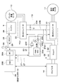
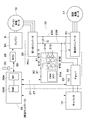
- FIG. 1 is a front view showing a hydraulic excavator according to a first embodiment. It is a block diagram which shows the structure of the electric system and hydraulic system of a hydraulic shovel. It is a block diagram which expands and shows the electric system in FIG. It is a block diagram which shows the structure of the electric system and hydraulic system of the hydraulic shovel by 2nd Embodiment.
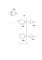
- FIG. 5 is an enlarged block diagram illustrating a gate circuit and the like in FIG. 4.
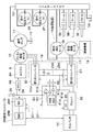
- It is a block diagram which shows the structure of the electric system and hydraulic system of the hydraulic shovel by 3rd Embodiment.
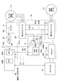
- It is a block diagram which shows the structure of the electric system and hydraulic system of the hydraulic shovel by 4th Embodiment. It is the same block diagram as FIG. 3 which shows the structure of the electric system by the 1st modification. It is the same block diagram as FIG. 3 which shows the structure of the electric system by the 2nd modification.
- FIG. 1 to 3 show a construction machine according to a first embodiment of the present invention.
- a hybrid hydraulic excavator 1 is a typical example of a hybrid construction machine.
- a hybrid hydraulic excavator 1 (hereinafter referred to as a hydraulic excavator 1) includes a self-propelled crawler-type lower traveling body 2, a slewing bearing device 3 provided on the lower traveling body 2, and the slewing bearing device 3.
- the upper revolving body 4 that is turnably mounted on the lower traveling body 2 and constitutes a vehicle body (base) together with the lower traveling body 2 and the earth and sand excavation work that is attached to the front side of the upper revolving body 4 so as to be able to move up and down. It is comprised including the working device 5 which performs etc.
- the lower traveling body 2 includes a track frame 2A, drive wheels 2B provided on the left and right sides of the track frame 2A, and drive wheels 2B on the left and right sides of the track frame 2A on the opposite side in the front and rear directions.
- An idler wheel 2C is provided, and a drive wheel 2B and a crawler belt 2D wound around the idler wheel 2C (both are shown only on the left side).
- the left and right drive wheels 2B are rotationally driven by left and right traveling hydraulic motors 2E and 2F (see FIG. 2), which are hydraulic motors (hydraulic actuators).
- the slewing bearing device 3 is attached to the upper side of the center portion of the track frame 2A.
- the working device 5 includes a boom 5A attached to the front side of a revolving frame 6 to be described later, an arm 5B attached to the tip of the boom 5A so as to be able to move up and down, and a pivot on the tip of the arm 5B.
- the bucket 5C is movably mounted, and includes a boom cylinder 5D, an arm cylinder 5E, and a bucket cylinder 5F, each of which includes a hydraulic cylinder (hydraulic actuator) that drives the bucket 5C.
- the upper revolving structure 4 includes a revolving frame 6 that forms a strong support structure.
- the swivel frame 6 is mounted on the lower traveling body 2 via the swivel bearing device 3 so as to be swivelable.
- the slewing bearing device 3 is attached to the lower surface side of the slewing frame 6.
- a cab 7, a counterweight 8, an engine 9, an assist power generation motor 10, a hydraulic pump 11, a power storage device 14, a turning device 15, a power conversion device 19 and the like are provided on the turning frame 6.
- the cab 7 is provided on the left front side of the revolving frame 6.
- a driver's seat on which an operator is seated is provided in the cab 7.
- a travel operation lever / pedal connected to a control valve 13 described later, a work operation lever, and the like are disposed.
- the counterweight 8 is attached to the rear end side of the revolving frame 6.
- the counterweight 8 balances the weight with the work device 5.
- the engine 9 is provided on the turning frame 6 between the cab 7 and the counterweight 8.
- the engine 9 is configured using, for example, a diesel engine, and is mounted as an internal combustion engine of the hybrid excavator 1 on the upper swing body 4 in a horizontally placed state extending in the left and right directions.
- An assist generator motor 10 and a hydraulic pump 11 described later are connected to the output side of the engine 9.
- the engine 9 is constituted by an electronically controlled engine, and for example, the fuel supply amount is variably controlled by a fuel injection device 9A such as an electronically controlled injection valve. That is, the fuel injection device 9A is an injection amount (fuel injection amount) of fuel injected into a cylinder (not shown) of the engine 9 based on a control signal output from an engine control unit (ECU) 28 described later. Is controlled variably. As a result, the engine 9 operates at a rotational speed corresponding to the driving operation of the operator, the operating state of the vehicle, and the like. Further, when an engine stop switch 30 described later is operated, the engine 9 stops the fuel injection of the fuel injection device 9A according to a command from the engine control unit 28, and the engine 9 stops.
- a fuel injection device 9A such as an electronically controlled injection valve. That is, the fuel injection device 9A is an injection amount (fuel injection amount) of fuel injected into a cylinder (not shown) of the engine 9 based on a control signal output from an engine control unit (ECU) 28 described later
- the assist generator motor 10 as a generator motor is connected to the engine 9.
- the assist power generation motor 10 is composed of, for example, a permanent magnet type synchronous motor, and generates electric power by being rotationally driven by the engine 9, or assists (assists) driving of the engine 9 by being supplied with electric power. is there. That is, the assist power generation motor 10 assists the drive of the engine 9 by being supplied with power through a function (generator function) for generating power by being rotationally driven by the engine 9 and DC buses 23A and 23B described later. Function (electric motor function).
- the electric power generated by the assist power generation motor 10 is supplied to a second inverter 21 and a chopper 22 to be described later via a first inverter 20 and DC buses 23A and 23B to be described later to drive the swing electric motor 17 and the power storage device 14. Is charged (storage).
- the assist power generation motor 10 is driven by electric power charged in the power storage device 14 (or regenerative electric power of the swing electric motor 17).
- a plurality of hydraulic pumps 11 and a hydraulic oil tank 12 constitute a hydraulic source.
- the hydraulic pump 11 is constituted by, for example, a swash plate type, an oblique axis type, or a radial piston type hydraulic pump, and is driven by the engine 9 and the assist power generation motor 10.
- the hydraulic pump 11 drives each hydraulic actuator, that is, the traveling hydraulic motors 2E and 2F of the lower traveling body 2, the boom cylinder 5D, the arm cylinder 5E, the bucket cylinder 5F of the working device 5, and the swing hydraulic motor 16 described later.
- the hydraulic oil in the hydraulic oil tank 12 is boosted and discharged toward a control valve 13 described later.
- the control valve 13 is provided on the turning frame 6.
- the control valve 13 includes a plurality of hydraulic control valves that control the hydraulic actuators (specifically, the traveling motors 2E and 2F, the cylinders 5D and 5E and 5F of the working device 5, and the swing hydraulic motor 16). ing.
- the control valve 13 switches supply and discharge of the pressure oil supplied from the hydraulic pump 11 according to a hydraulic signal or the like based on the operation of the operation lever / pedal for driving or the operation lever for work (discharge amount of pressure oil) And control the discharge direction).
- hydraulic oil (pressure oil) supplied from the hydraulic pump 11 to the control valve 13 is appropriately distributed to the respective hydraulic actuators 2E, 2F, 5D, 5E, 5F, 16 and these hydraulic actuators 2E, 2F, 5D, 5E, 5F, 16 can be driven (expanded, reduced, rotated).
- the power storage device 14 is provided on the turning frame 6.
- the power storage device 14 is connected to the assist power generation motor 10 and the swing electric motor 17 via a chopper 22, a first inverter 20, and a second inverter 21 described later.
- the power storage device 14 is configured using, for example, an electric double layer capacitor and stores electric charges. That is, the power storage device 14 charges (accumulates) the power generated by the assist power generation motor 10 and the power generation (regenerative power) generated during the turn deceleration by the swing electric motor 17, or the charged power is transferred to the assist power generation motor 10 and the turn.
- the electric motor 17 is discharged (powered).
- a battery such as a lithium ion battery can be used as the power storage device 14 in addition to the capacitor.
- the turning device 15 is provided on the upper turning body 4 (the turning frame 6).
- the turning device 15 is configured to turn the upper turning body 4 relative to the lower traveling body 2 by transmitting a rotational force to the turning bearing device 3.
- the turning device 15 is configured as a so-called hybrid turning device in which the turning hydraulic motor 16 and the turning electric motor 17 cooperate to drive the upper turning body 4 to turn.
- the turning device 15 includes a turning hydraulic motor 16 constituted by a hydraulic actuator such as a swash plate type hydraulic motor, a turning electric motor 17 as a turning electric motor constituted by an electric actuator such as an electric motor, and a turning hydraulic pressure.
- a speed reduction mechanism 18 that decelerates the rotation input from the motor 16 and / or the swing electric motor 17, and an output as a pinion that outputs the rotation decelerated by the speed reduction mechanism 18 to the swing bearing device 3 (inner teeth of the inner ring). And a shaft (not shown).
- the swing electric motor 17 rotates the upper swing body 4 in cooperation with the swing hydraulic motor 16.
- the swing electric motor 17 is configured by using, for example, a permanent magnet type synchronous motor, and is driven by power generated by the assist power generation motor 10 and power of the power storage device 14. Further, the turning electric motor 17 generates electric power by converting energy generated when the turning operation is decelerated into electric energy. That is, the turning electric motor 17 has a function (electric motor function) for turning the upper turning body 4 by being supplied with electric power via DC buses 23A and 23B, which will be described later, and a kinetic energy of the upper turning body 4 at the time of turning deceleration ( It has a function (generator function) for converting (rotational energy) into electric energy (regenerative power generation).
- the generated electric power (regenerative electric power) of the swing electric motor 17 is supplied to the first inverter 20 and the chopper 22 which will be described later via the second inverter 21 and the DC buses 23A and 23B which will be described later. Then, the power storage device 14 is charged (power storage).
- the electric system of the excavator 1 includes a first inverter 20 and a second inverter 21 described later in addition to the assist power generation motor 10, the power storage device 14, and the swing electric motor 17 described above.
- the first inverter 20, the second inverter 21, the chopper 22, the inverter controller 24, and the chopper controller 25 are collectively (unitized) as a power conversion device (PCU: power control unit) 19. It is mounted on the upper swing body 4.
- the first inverter 20 is used as an assist power generation inverter (assist power generation switching device).
- the first inverter 20 is electrically connected to the assist power generation motor 10.
- the first inverter 20 controls the driving of the assist power generation motor 10.
- the first inverter 20 is configured by using a plurality of (for example, six) switching elements made of, for example, transistors, insulated gate bipolar transistors (IGBTs), etc., and a pair of DC buses 23A and 23B, which will be described later. It is connected. Opening and closing of the switching element of the first inverter 20 is controlled by an inverter controller 24 described later.
- the first inverter 20 converts the power generated by the assist power generation motor 10 into DC power and supplies it to the DC buses 23A and 23B.
- the first inverter 20 when the assist generator motor 10 is driven, the first inverter 20 generates three-phase (U-phase, V-phase, W-phase) AC power from the DC power of the DC buses 23A, 23B, and the assist generator motor 10 To supply.
- the second inverter 21 is used as a turning inverter (turning switching device).
- the second inverter 21 is electrically connected to the swing electric motor 17.
- the second inverter 21 controls the driving of the swing electric motor 17.
- the second inverter 21 is configured by using a plurality of (for example, six) switching elements in substantially the same manner as the first inverter 20, and is connected to a pair of DC buses 23A and 23B described later. Yes. Opening and closing of the switching element of the second inverter 21 is controlled by an inverter controller 24 described later.
- the second inverter 21 During the turning drive of the swing electric motor 17, the second inverter 21 generates three-phase (U-phase, V-phase, W-phase) AC power from the DC power of the DC buses 23 ⁇ / b> A and 23 ⁇ / b> B and supplies it to the swing electric motor 17. To do. On the other hand, when the swing electric motor 17 is decelerated (regeneration), the second inverter 21 converts the regenerative power generated by the swing electric motor 17 into DC power and supplies it to the DC buses 23A and 23B.
- the chopper 22 has one end connected to the power storage device 14 and the other end connected to a pair of DC buses 23A and 23B.
- the chopper 22 and the inverters 20 and 21 are electrically connected to each other via a pair of DC buses 23A and 23B.
- the chopper 22 includes a plurality of (for example, two) switching elements made of, for example, an IGBT and a reactor.
- the chopper 22 is controlled to be opened and closed by a chopper controller 25 described later.
- step-down chopper When the power storage device 14 is charged, the chopper 22 functions as a step-down circuit (step-down chopper), and for example, steps down a DC voltage supplied from the DC buses 23A and 23B and supplies the voltage to the power storage device 14.
- step-down chopper step-down circuit
- the chopper 22 functions as a booster circuit (boost chopper), boosts the DC voltage supplied from the power storage device 14 and supplies the boosted DC voltage to the DC buses 23
- the inverters 20 and 21 and the chopper 22 are connected to each other through a pair of DC buses 23A and 23B on the positive electrode side (plus side) and the negative electrode side (minus side).
- a smoothing capacitor C is connected to the DC buses 23A and 23B in order to stabilize the voltage of the DC buses 23A and 23B. For example, a predetermined DC voltage of about several hundred volts is applied to the DC buses 23A and 23B.
- the inverter controller 24 is used as a controller (control device). That is, the inverter controller 24 controls the inverters 20 and 21.
- the inverter controller 24 is composed of, for example, a microcomputer or the like, and uses various signals such as operation command signals to control commands for the first inverter 20 and the second inverter 21 (for example, the inverters 20 and 21). A gate signal for controlling opening and closing of the switching element), and driving control (rotational speed control) of the motors 10 and 17 is performed.
- the configuration of the inverter controller 24 will be described in detail later.
- the chopper controller 25 is used as a controller (control device). That is, the chopper controller 25 controls the chopper 22.
- the chopper controller 25 is constituted by, for example, a microcomputer and generates a control command (for example, a gate signal for controlling opening / closing of the switching element) to the chopper 22 using various signals such as an operation command signal. Then, control is performed such that the voltages of the DC buses 23A and 23B are held near a predetermined constant value.
- the inverter controller 24 and the chopper controller 25 are connected to an integrated controller (main control unit) 26 including a malfunction monitoring / malfunction processing control section (MC) 26A, an energy management control section (EMC) 26B, etc. 27 are electrically connected to each other via a terminal 27 to form a CAN (Control Area Network).
- the integrated controller 26 is also composed of a microcomputer or the like, generates control commands for the inverter controller 24, the chopper controller 25, and the like, controls the drive of the assist power generation motor 10, the swing electric motor 17, the malfunction monitoring of the electric system, and energy management. Etc. are controlled.
- the malfunction monitoring / malfunction processing control unit 26A controls malfunction monitoring of the electric system. Specifically, the malfunction monitoring / synchronization processing control unit 26A has experienced malfunctions, abnormalities, warnings, etc. in the electric system such as the power conversion device 19, the assist power generation motor 10, the swing electric motor 17, and the power storage device 14. When it is determined that a malfunction has occurred, an electric system malfunction signal (a signal indicating malfunction) that is a signal to that effect is output to the inverter controller 24 (or gate 24D). To do.
- the power storage command of the power storage device 14 that increases or decreases depending on the difference between the energy consumed by the swing electric motor 17 during acceleration and the energy regenerated during deceleration is supplied to the assist power generation motor 10 as a power generation command or an assist command.
- the output is controlled to keep within a predetermined range.
- the integrated controller 26 is electrically connected to an engine control unit 28 called ECU via a communication line 29.
- the engine control unit 28 controls the engine 9 (rotational speed control or the like), and is connected to, for example, a fuel injection device 9A of the engine 9.
- the engine control unit 28 variably controls the fuel injection amount (fuel supply amount) by the fuel injection device 9A into the cylinder of the engine 9 so that the engine control unit 28 can rotate at a rotational speed corresponding to the driving operation of the operator or the operating state of the vehicle.
- the engine 9 is operated.
- the engine control unit 28 controls the fuel injection amount of the fuel injection device 9A based on, for example, a command from an engine speed instruction dial (not shown) operated by an operator, a command from the integrated controller 26, and the like. Do.
- the engine stop switch 30 is a switch for stopping the engine 9.
- the engine stop switch 30 is connected to the engine control unit 28 and the inverter controller 24 (or the gate 24D).
- the engine stop switch 30 is configured to shut off the gate signal output from the inverter controller 24 in addition to stopping the engine 9 when operated. That is, the engine stop switch 30 is configured as a both stop switch that stops both the engine 9 and the assist generator motor 10 (and the swing electric motor 17).
- the gate signal is cut off by the engine stop switch 30 regardless of the PWM signal generated by the inverter controller 24 (a signal corresponding to the switching element open / close ratio). That is, the gate signal is cut off by the engine stop switch 30 regardless of the PWM signal for the first inverter 20 and the PWM signal for the second inverter 21 generated by the inverter controller 24.
- the inverter controller 24 outputs a gate signal for controlling opening and closing of the switching element of the first inverter 20 and the switching element of the second inverter 21 to control the assist generator motor 10 and the swing electric motor 17 ( For example, the rotational speed is controlled).
- the inverter controller 24 generates a PWM signal generation circuit (PWMSGC) 24A as a PWM signal generation unit that generates a PWM signal for the switching element of the first inverter 20 and a PWM signal for the switching element of the second inverter 21.
- PWMSGC PWM signal generation circuit
- a first gate signal generation circuit 24B as a gate signal generation unit that outputs a gate signal to the first inverter 20 based on the PWM signal generated by the PWM signal generation circuit 24A, and a PWM signal generation circuit 24A.
- a second gate signal generation circuit 24C as a gate signal generation unit that outputs a gate signal to the second inverter 21 based on the PWM signal thus generated.
- the inverter controller 24 is provided with an OR gate 24D.
- the OR gate 24D generates a first gate signal when an at least one of an engine stop switch signal (signal indicating stop), which will be described later, and an electric system malfunction signal (signal indicating malfunction) are input. This is for outputting a signal to stop the output of the gate signal to the circuit 24B and the second gate signal generation circuit 24C.
- the inverter controller 24 receives a torque command, a power generation command or an assist command from the integrated controller 26, and outputs a three-phase PWM signal from the PWM signal generation circuit 24A according to the command.
- Each of the gate signal generation circuits 24B and 24C is based on the three-phase PWM signal output from the PWM signal generation circuit 24A (PWM signal corresponding to the open / close ratio of each switching element).
- Gate signals are output to the upper and lower arms of the three phases and the upper and lower arms of the three phases of the second inverter 21, respectively.
- the switching element in the 1st inverter 20 and the switching element in the 2nd inverter 21 open and close based on each gate signal, and a three-phase alternating current is produced
- the assist power generation motor 10 and the swing electric motor 17 are driven with the commanded torque.
- an engine stop switch signal (a signal indicating the stop) is output from the engine stop switch 30, and the engine stop switch signal is output from the engine control unit. 28.
- an engine stop switch signal stop signal
- the engine control unit 28 outputs a signal for stopping fuel injection to the fuel injection device 9A of the engine 9. Thereby, the fuel injection of the fuel injection device 9A is stopped, and the engine 9 is stopped.
- the engine stop switch signal (stop signal) output from the engine stop switch 30 is input not only to the engine control unit 28 but also to the inverter controller 24 (or the gate 24D thereof).
- the inverter controller 24 receives the first inverter 20 and the first inverter 20 from the gate signal generation circuits 24B and 24C. The gate signal output to the inverter 21 of 2 is cut off, and the electric system is stopped.
- the inverter controller 24 (or the gate 24D thereof) also receives the electric system malfunction signal (signal indicating malfunction) from the integrated controller 26. That is, the malfunction monitoring / malfunction processing control unit 26A of the integrated controller 26 outputs an electric system malfunction signal, which is a signal to that effect, when the malfunction condition, abnormality, warning, or the like occurs in the electric system. (Or OR gate 24D).
- the energy management control unit 26B of the integrated controller 26 generates an electric system malfunction signal (for example, malfunction monitoring / stabilization) that becomes a signal to that effect when the amount of power stored in the power storage device 14 falls outside a predetermined range. Output to the inverter controller 24 (or its gate 24D) via the processing control unit 26A.
- the inverter controller 24 receives the first inverter 20 and the first inverter 20 from the gate signal generation circuits 24B and 24C even when an electric system malfunction signal (a signal indicating malfunction) is input from the integrated controller 26.
- the gate signal output to the inverter 21 of 2 is cut off, and the electric system is stopped.
- the inverter controller 24 includes an engine stop switch signal from the engine stop switch 30 (stop signal) and an electric system malfunction signal from the integrated controller 26 (malfunction signal).
- stop signal an electric system malfunction signal from the integrated controller 26
- the gate signals output from the gate signal generation circuits 24B and 24C to the first inverter 20 and the second inverter 21 are cut off, and the electric system is stopped.
- the gate signal generation circuits 24B and 24C of the inverter controller 24 are controlled by an inhibition terminal (inhibit terminal) 24B1, which stops the output of the gate signal based on the operation of the engine stop switch 30 and / or a command from the integrated controller 26. 24C1 is provided.
- An engine stop switch signal from the engine stop switch 30 and an electric system malfunction signal from the malfunction monitoring / malfunction processing control unit 26A of the integrated controller 26 are selectively input to the inhibition terminals 24B1 and 24C1.
- the inverter controller 24 includes a two-input OR gate 24D.
- One input side of the OR gate 24D is connected to the engine stop switch 30, and the other input side is connected to the malfunction monitoring / malfunction processing control unit 26A of the integrated controller 26.
- the output side of the OR gate 24D is connected to the inhibition terminals 24B1 and 24C1 of the gate signal generation circuits 24B and 24C.
- the engine stop switch signal is inverted and input to one input side of the OR gate 24D
- the electric system malfunction signal is inverted and input to the other input side of the OR gate 24D.
- the calculated output is inverted and output. In other words, it is configured as an inverting input NOR gate.
- the engine stop switch 30 outputs 1 when it is not operated (OFF), and outputs 0 when operated by an operator or the like to stop the engine 9 (turns ON).
- the malfunction monitoring / malfunction processing control unit 26A of the integrated controller 26 outputs 1 when normal, and outputs 0 when determined to be malfunctioning.
- the OR gate 24D changes its output (inverted output) from the high level (1) to the low level (0). (The output becomes low level).
- the output (inverted output) of the OR gate 24D is input to the inhibition terminals 24B1 and 24C1 of the gate signal generation circuits 24B and 24C.
- the gate signal generation circuits 24B and 24C when the signal levels of the inhibition terminals 24B1 and 24C1 change from the high level (1) to the low level (0), the gate signals to the first inverter 20 and the second inverter 21. Stop the output of.
- the gate signal output to the first inverter 20 and the second inverter 21 may be cut off. it can. As a result, the assist power generation motor 10 and the swing electric motor 17 can be stopped.
- the engine stop switch 30 and the integrated controller 26 are directly connected to the inhibition terminals 24B1 and 24C1 of the gate signal generation circuits 24B and 24C via the OR gate 24D. It is connected. Therefore, based on the electrical signals (engine stop switch signal, electric system malfunction signal) output from the engine stop switch 30 and / or the integrated controller 26 without using software installed in the inverter controller 24. The gate signal output from the gate signal generation circuits 24B and 24C can be stopped.
- the operation of the engine stop switch 30 causes the gate signal to be output to the inhibition terminals 24B1 and 24C1 of the gate signal generation circuits 24B and 24C via the OR gate 24D.
- a stop signal is input.
- the assist power generation motor 10 and the swing electric motor 17 can be quickly stopped together with the stop of the engine 9.
- the hydraulic excavator 1 according to the first embodiment has the above-described configuration, and the operation thereof will be described next.
- the operator gets into the cab 7 and sits in the driver's seat. In this state, the operator operates the operation lever / pedal for traveling to supply pressure oil from the control valve 13 to the traveling motors 2E and 2F of the lower traveling body 2, and the left and right drive wheels 2B are moved.
- the hydraulic excavator 1 can be moved forward or backward by driving. Further, the operator can perform excavation work of earth and sand by turning the upper swing body 4 or moving the working device 5 up and down by operating the operation lever.
- an engine stop switch signal (a signal indicating stop) is sent from the engine stop switch 30 to the engine control unit 28. It is input to the inverter controller 24 (or its gate 24D). Thereby, the fuel injection from the fuel injection device 9A of the engine 9 is stopped, and the engine 9 is stopped. In addition, the gate signal output from the gate signal generation circuits 24B and 24C of the inverter controller 24 is stopped, and the assist power generation motor 10 and the swing electric motor 17 are also stopped.
- the inverter controller 24 when the engine stop switch 30 is operated, in addition to stopping the engine 9, the inverter controller 24 outputs to the first inverter 20 and the second inverter 21. Interrupts the gate signal. Therefore, the assist power generation motor 10 and the swing electric motor 17 can be stopped together with the stop of the engine 9 based on the operation of the engine stop switch 30.
- the engine stop switch 30 is operated to operate the engine 9 and the assist power generation.
- the hydraulic pump 11 driven by the motor 10 can be quickly stopped.
- the turning electric motor 17 can also be stopped, and the turning device 15 can be quickly stopped. As a result, the excavator 1 can be stopped immediately.
- the gate signal is cut off regardless of the PWM signal generated by the inverter controller 24. That is, even if the PWM signal is generated by the PWM signal generation circuit 24A of the inverter controller 24 based on the command of the integrated controller 26, etc., it is based on the electrical signal (engine stop switch signal) output from the engine stop switch 30.
- the gate signal output from the gate signal generation circuits 24B and 24C is stopped. For this reason, even if the inverter controller 24 generates a PWM signal indicating that the assist generator motor 10 and the swing electric motor 17 continue to rotate, the gate signal is blocked, and the assist generator motor 10 and the swing electric motor 17 are It can be stopped reliably.
- the engine stop switch 30 when the engine stop switch 30 is operated to output an engine stop switch signal (a signal indicating the stop) from the engine stop switch 30, the engine stop switch signal is It is directly input to the inhibition terminals 24B1 and 24C1 of the gate signal generation circuits 24B and 24C (via the OR gate 24D), and the gate signal output by the gate signal generation circuits 24B and 24C can be stopped.
- the gate signal output from the gate signal generation circuits 24B and 24C to the first inverter 20 and the second inverter 21 can be stopped, and the assist generator motor 10 and the swing electric motor 17 can be stopped reliably. it can.
- FIGS. 4 and 5 show a construction machine according to a second embodiment of the present invention.
- a feature of the second embodiment resides in that a gate circuit for cutting off the PWM signal is provided between the PWM signal generation unit and the gate signal generation unit.
- the same components as those in the first embodiment described above are denoted by the same reference numerals, and description thereof is omitted.
- an inverter controller 31 is an inverter controller used in the second embodiment instead of the inverter controller 24 of the first embodiment.
- the inverter controller 31 sends a gate signal to the first inverter 20 based on the PWM signal generation circuit 31A similar to the PWM signal generation circuit 24A of the first embodiment and the PWM signal generated by the PWM signal generation circuit 31A.
- the circuit includes a second gate signal generation circuit 31C and a gate circuit 32 described later.
- the inverter controller 31 is provided with an OR gate 31D which is different from the OR gate 24D of the first embodiment in that it is not connected to the inhibition terminals 24B1 and 24C1 of the gate signal generation circuits 24B and 24C. .
- the OR gate 31D is connected to the gate circuit 32.
- the gate circuit 32 is provided between the PWM signal generation circuit 31A and the gate signal generation circuits 31B and 31C.
- the gate circuit 32 blocks the input of the PWM signal to each of the gate signal generation circuits 31B and 31C based on the operation of the engine stop switch 30.
- the engine stop switch signal from the engine stop switch 30 and the electric system malfunction signal from the malfunction monitoring / malfunction processing control unit 26A of the integrated controller 26 are selectively input to the gate circuit 32. Therefore, the input side of the gate circuit 32 is connected to the output side of the OR gate 31D, and the output of the OR gate 31D is input to the gate circuit 32.
- the number of PWM signals input from the PWM signal generation circuit 31A to the gate circuit 32 is six, and the gate circuit 32 includes six 2-input AND gates 32A and 32B. Since the six AND gates 32A and 32B have the same configuration, in FIG. 5, two AND gates, one AND gate 32A for the assist power generation motor and one AND gate 32B for the swing electric motor. 32A and 32B are shown.
- the gate circuit 32 one input side of the AND gates 32A and 32B is connected to the PWM signal generation circuit 31A. That is, one PWM signal is input to one input side of the AND gates 32A and 32B.
- the other input side of the AND gates 32A and 32B is connected to the output side of the OR gate 31D. That is, the output (inverted output) of the OR gate 31D is input to the other input side of the AND gates 32A and 32B.
- the engine stop switch 30 outputs 1 when it is not operated (OFF), and outputs 0 when it is operated (turned ON) by an operator or the like to stop the engine 9.
- the malfunction monitoring / malfunction processing control unit 26A of the integrated controller 26 outputs 1 when normal, and outputs 0 when determined to be malfunctioning. Accordingly, when at least one of the engine stop switch signal and the electric system malfunction signal is switched from 1 to 0, the output (inverted output) of the OR gate 31D changes from the high level (1) to the low level (0). ) And one input of the AND gates 32A and 32B is turned OFF (0).
- the PWM signal input from the PWM signal generation circuit 31A to each of the gate signal generation circuits 31B and 31C is cut off, and the output of the gate signal of each of the gate signal generation circuits 31B and 31C is stopped.
- the assist power generation motor 10 and the swing electric motor 17 can be stopped.
- an electrical signal (engine stop switch signal, electric system malfunction) output from the engine stop switch 30 and / or the integrated controller 26 without using software installed in the inverter controller 31.
- the gate circuit 32 can prevent the PWM signal generated by the PWM signal generation circuit 31A from being input to the gate signal generation circuits 31B and 31C.
- the operation of the engine stop switch 30 causes the gate signal generation circuits 31B and 31C to be supplied to the AND gates 32A and 32B of the gate circuit 32 via the OR gate 31D.
- a signal for stopping the input of the PWM signal to is input.
- the assist power generation motor 10 and the swing electric motor 17 can be quickly stopped together with the stop of the engine 9.
- the second embodiment is configured to block the PWM signal using the gate circuit 32 as described above, and the basic operation is not particularly different from that according to the first embodiment described above. .
- the engine stop switch signal (a signal indicating a stop) is output from the engine stop switch 30 by operating the engine stop switch 30 by operating the engine stop switch 30
- the engine stop switch signal is The input of the PWM signal to the gate signal generation circuits 31B and 31C can be blocked by being input to the gate circuit 32 (and the AND gates 32A and 32B thereof) via the OR gate 24D.
- the output of the gate signal to each of the first inverter 20 and the second inverter 21 from each gate signal generation circuit 31B, 31C can be stopped, and the assist power generation motor 10 and the swing electric motor 17 can be stopped reliably. Can do.
- FIG. 6 shows a construction machine according to a third embodiment of the present invention.
- a feature of the third embodiment is that an OR gate is provided in a controller (integrated controller) different from the inverter controller, and an engine stop switch is connected to the OR gate of the other controller. Note that in the third embodiment, the same components as those in the first embodiment and the second embodiment described above are denoted by the same reference numerals, and description thereof is omitted.
- an inverter controller 41 is an inverter controller used in the third embodiment in place of the inverter controller 24 of the first embodiment.
- the inverter controller 41 includes a PWM signal generation circuit 41A similar to the PWM signal generation circuit 24A of the first embodiment, and the inhibition terminals 41B1, similarly to the gate signal generation circuits 24B and 24C of the first embodiment. Gate signal generation circuits 41B and 41C having 41C1 are included.
- the third embodiment is different from the inverter controller 24 of the first embodiment in that the inverter controller 41 does not have an OR gate (the inverter controller 41 is not provided with an OR gate).
- the integrated controller 42 is an integrated controller used in the third embodiment in place of the integrated controller 26 of the first embodiment.
- the integrated controller 42 includes the same malfunction monitoring / malfunction processing control unit 42A as in the first embodiment and an energy management control unit 42B similar to that in the first embodiment.
- the integrated controller 42 is provided with an OR gate 43 described later.
- the engine stop switch 30 is connected to the integrated controller 42 (or the gate 43 thereof) with the configuration in which the integrated controller 42 has the OR gate 43 (the OR gate 43 is provided in the integrated controller 42). Has been.
- the OR gate 43 receives the engine stop switch signal from the engine stop switch 30 and the electric system malfunction signal from the malfunction monitoring / malfunction processing control unit 42A of the integrated controller 42. As with the OR gate 24D of the first embodiment, the OR gate 43 receives at least one of an engine stop switch signal (stop signal) and an electric system malfunction signal (malfunction signal). Then, a signal for stopping the output of the gate signal is output to each of the gate signal generation circuits 41B and 41C.
- One input side of the OR gate 43 is connected to the engine stop switch 30, and the other input side is connected to the malfunction monitoring / malfunction processing control unit 42A of the integrated controller 42.
- the output side of the OR gate 43 is connected to the inhibition terminals 41B1 and 41C1 of the gate signal generation circuits 41B and 41C.
- the engine stop switch signal is inverted and input to one input side of the OR gate 43, and the electric system malfunction signal is inverted and input to the other input side of the OR gate 43.
- the calculated output is inverted and output. In other words, it is configured as an inverting input NOR gate.
- the engine stop switch 30 outputs 1 when it is not operated (OFF), and outputs 0 when operated by an operator or the like to stop the engine 9 (turns ON).
- the malfunction monitoring / malfunction processing control unit 42A of the integrated controller 42 outputs 1 when normal, and outputs 0 when determined to be malfunctioning.
- the OR gate 43 changes its output (inverted output) from the high level (1) to the low level (0). (The output becomes low level).
- the output of the OR gate 43 (inverted output) is input to the inhibition terminals 41B1 and 41C1 of the gate signal generation circuits 41B and 41C.
- the gate signal generation circuits 41B and 41C are connected to the first inverter 20 and the second inverter 21. Stop the output of. Thereby, the gate signal output to the 1st inverter 20 and the 2nd inverter 21 can be interrupted
- an electrical signal (engine stop switch signal, electric system malfunction) output from the engine stop switch 30 and / or the integrated controller 42 without using software installed in the inverter controller 41.
- Signal from the gate signal generation circuits 41B and 41C can be stopped.
- the gate signal is output to the inhibition terminals 41B1 and 41C1 of the gate signal generation circuits 41B and 41C through the OR gate 43 by the operation of the engine stop switch 30.
- a stop signal is input.
- the assist power generation motor 10 and the swing electric motor 17 can be quickly stopped together with the stop of the engine 9.
- the third embodiment is configured such that the gate signal is cut off via the OR gate 43 as described above, and there is no particular difference in basic operation from that according to the first embodiment described above.
- the engine stop switch 30 can be connected to the OR gate 43 of the integrated controller 42. Thereby, the freedom degree of the wiring of the engine stop switch 30 can be improved.
- the case where the output of the OR gate 43 is input to the inhibition terminals 41B1 and 41C1 of the gate signal generation circuits 41B and 41C has been described as an example.
- the present invention is not limited to this, and the gate circuit 32 of the second embodiment is provided between the PWM signal generation circuit 41A and each of the gate signal generation circuits 41B and 41C, as indicated by a broken line in FIG.
- the same gate circuit 51 may be provided, and the output of the OR gate 43 may be input to an AND gate (not shown) of the gate circuit 51.
- FIG. 7 shows a construction machine according to a fourth embodiment of the present invention.
- a feature of the fourth embodiment is that a relay circuit is provided between the gate signal generation unit and the assist power generation inverter. Note that in the fourth embodiment, the same components as those in the first to third embodiments described above are denoted by the same reference numerals, and description thereof is omitted.
- the inverter controller 61 is an inverter controller used in the fourth embodiment instead of the inverter controller 24 of the first embodiment.
- the inverter controller 61 sends a gate signal to the first inverter 20 based on the PWM signal generation circuit 61A similar to the PWM signal generation circuit 24A of the first embodiment and the PWM signal generated by the PWM signal generation circuit 61A.
- a second gate signal generation circuit 61C a second gate signal generation circuit 61C.
- the inverter controller 61 is provided with an OR gate 61D which is different from the OR gate 24D of the first embodiment in that it is not connected to the inhibition terminals 24B1 and 24C1 of the gate signal generation circuits 24B and 24C. .
- the OR gate 61D is connected to a relay circuit 62 described later.
- the relay circuit 62 is provided between the gate signal generation circuits 61B and 61C and the first inverter 20 and the second inverter 21.
- the relay circuit 62 cuts off the connection between the gate signal generation circuits 61B and 61C and the first inverter 20 and the second inverter 21 based on the operation of the engine stop switch 30.
- the engine stop switch signal from the engine stop switch 30 and the electric system malfunction signal from the malfunction monitoring / malfunction processing control unit 26A of the integrated controller 26 are selectively input to the relay circuit 62.
- the input side of the relay circuit 62 is connected to the output side of the OR gate 61D, and the output of the OR gate 61D is input to the relay circuit 62.
- the engine stop switch 30 outputs 1 when it is not operated (OFF), and outputs 0 when it is operated (turned ON) by an operator or the like to stop the engine 9.
- the malfunction monitoring / malfunction processing control unit 26A of the integrated controller 26 outputs 1 when normal, and outputs 0 when determined to be malfunctioning. Accordingly, when at least one of the engine stop switch signal and the electric system malfunction signal is switched from 1 to 0, the output (inverted output) of the OR gate 61D changes from the high level (1) to the low level (0). ) And output to the relay circuit 62.
- the relay circuit 62 the relay is activated as the input is changed from the high level (1) to the low level (0), and the gate signal generation circuits 61B and 61C, the first inverter 20, and the second inverter 20 The connection with the inverter 21 is interrupted. Thereby, the gate signal output from each gate signal generation circuit 61B, 61C is no longer input into the 1st inverter 20 and the 2nd inverter 21, and the assist electric power generation motor 10 and the turning electric motor 17 stop.
- an electrical signal (engine stop switch signal, electric system malfunction) output from the engine stop switch 30 and / or the integrated controller 26 without using software installed in the inverter controller 61.
- Signal can be prevented from being input to the first inverter 20 and the second inverter 21 from the gate signal generation circuits 61B and 61C.
- the operation of the engine stop switch 30 causes the gates for the first inverter 20 and the second inverter 21 to be connected to the relay circuit 62 via the OR gate 61D.
- a signal for stopping signal input is input.
- the assist power generation motor 10 and the swing electric motor 17 can be quickly stopped together with the stop of the engine 9.
- the fourth embodiment is configured such that the gate signal is cut off using the relay circuit 62 as described above, and the basic operation is not particularly different from that according to the first embodiment described above. .
- the engine stop switch signal (a signal indicating a stop) is output from the engine stop switch 30 by operating the engine stop switch 30
- the engine stop switch signal is The gate signal input to the first inverter 20 and the second inverter 21 can be cut off by being input to the relay circuit 62 (through the OR gate 61D).
- the assist electric power generation motor 10 and the turning electric motor 17 can be stopped reliably.
- the case where the engine stop switch 30 and the malfunction monitoring / malfunction processing control unit 26A of the integrated controller 26 are connected to the OR gate 24D has been described as an example. More specifically, the engine stop switch signal is inverted and input to one input side of the OR gate 24D, the electric system malfunction signal is inverted and input to the other input side of the OR gate 24D, and OR operation is performed from the OR gate 24D.
- the case where the output is inverted and output (when configured as an inverted input NOR gate) is described as an example.
- the present invention is not limited to this, and the engine stop switch 30 and the malfunction monitoring / malfunction processing control unit 26A of the integrated controller 26 are connected to the AND gate 71 as in the first modification shown in FIG. It is good also as a structure.
- the second embodiment, the third embodiment, and the fourth embodiment are connected to the OR gate 24D.
- the engine stop switch 30 and the malfunction monitoring / malfunction processing control unit 26A of the integrated controller 26 are connected to the OR gate 31D, and the OR gate 31D is connected to the AND gates 32A and 32B of the gate circuit 32.
- the present invention is not limited to this.
- an OR gate may be omitted as in the second modification shown in FIG. That is, the engine stop switch 30 and the malfunction monitoring / malfunction processing control unit 26A of the integrated controller 26 may be connected to the AND gates 81A, 81B, 81C, 81D constituting the gate circuit 81, respectively.
- the AND gates 81A and 81B connected to the engine stop switch 30, and the AND gates 81C and 81D connected to the malfunction monitoring / malfunction processing control unit 26A of the integrated controller 26, the PWM signal generation circuit 31A, and each A configuration may be employed in which the gate signal generation circuits 31B and 31C are provided in series. The same applies to the third embodiment.
- the relay circuit 62 is provided between the gate signal generation circuits 61B and 61C and the first inverter 20 and the second inverter 21 has been described as an example.
- the present invention is not limited thereto, and for example, a relay circuit may be provided between the PWM signal generation circuit (PWM signal generation unit) and the gate signal generation circuit (gate signal generation unit).
- the inverter controller 61 is provided in the OR gate 61D (the inverter controller 61 has the OR gate 61D).
- the present invention is not limited to this.
- an engine stop switch is provided in a part different from the inverter controller, such as a controller (for example, an integrated controller) different from the inverter controller.
- a controller for example, an integrated controller
- the AND gate 71 connected to the engine stop switch 30 may be provided in a part (for example, the integrated controller 26) different from the inverter controller 24.
- the gate signal output from the inverter controller 24, 31, 41, 61 is cut off based on at least one signal.
- the gate signal output from the inverter controller may be blocked based on only the engine stop switch signal (stop signal).
- the gate signal output from the inverter controller may be cut off.
- the assist generator motor 10 and the swing electric motor 17 are based on the engine stop switch signal from the engine stop switch 30 (and / or the electric system malfunction signal from the integrated controller 26). As an example, a case in which both are stopped is described. However, the present invention is not limited to this, and for example, only the assist generator motor (generator motor) may be stopped based on an engine stop switch signal (and / or a signal from the controller) from the engine stop switch. .
- the turning device 15 is a hybrid turning device constituted by the turning hydraulic motor 16 and the turning electric motor 17 has been described as an example.
- the present invention is not limited to this.
- the turning device may be an electric turning device (without a hydraulic motor) configured by a turning electric motor (electric motor) alone.
- the hydraulic excavator 1 has been described as an example of the construction machine.
- the present invention is not limited to this, and can be widely applied to hybrid construction machines including various work vehicles, work machines, and the like such as wheel loaders, hydraulic cranes, forklifts, and the like.
Abstract
An inverter controller (24) for controlling a first inverter (20) connected to an assist generator motor (10) is configured so as to include a first gate signal generation circuit (24B) for outputting a gate signal to the first inverter (20). The first gate signal generation circuit (24B) has a suppression terminal (24B1), and the suppression terminal (24B1) is connected to an engine stop switch (30). When the engine stop switch (30) is operated, an engine (9) is stopped, the output of a gate signal from the first gate signal generation circuit (24B) to the first inverter (20) is shutoff, and the assist generator motor (10) is stopped.
Description
本発明は、例えば油圧ショベル、ホイールローダ、油圧クレーン、フォークリフト等の建設機械に関し、エンジン(内燃機関)と電動機(アシスト発電モータ)の双方を動力源とするハイブリッド式の建設機械に関する。
The present invention relates to a construction machine such as a hydraulic excavator, a wheel loader, a hydraulic crane, a forklift, and the like, and relates to a hybrid construction machine using both an engine (internal combustion engine) and an electric motor (assist power generation motor) as power sources.
一般に、建設機械の代表例としての油圧ショベルは、走行用、作業用の動力源(原動機)としてガソリン、軽油等を燃料とするエンジンを備えている。この場合、油圧ショベルは、エンジンによって油圧ポンプを駆動することにより、油圧ポンプから吐出した圧油によって油圧モータ、油圧シリンダ等の油圧アクチュエータを作動させる構成となっている。油圧アクチュエータは、小型軽量で大出力が可能であり、建設機械のアクチュエータとして広く用いられている。
Generally, a hydraulic excavator as a typical example of a construction machine includes an engine that uses gasoline, light oil, or the like as a fuel as a power source (motor) for driving or working. In this case, the hydraulic excavator is configured to operate a hydraulic actuator such as a hydraulic motor or a hydraulic cylinder by the hydraulic oil discharged from the hydraulic pump by driving the hydraulic pump by the engine. Hydraulic actuators are small and light and capable of high output, and are widely used as construction machine actuators.
一方、走行用、作業用の動力源(原動機)としてエンジンと電動機(電動モータ)とを併用したハイブリッド式の油圧ショベルが提案されている。このハイブリッド式の油圧ショベルは、例えば、エンジンと、該エンジンによって駆動されることにより発電を行う発電機機能、および、電力供給されることによりエンジンの駆動を補助(アシスト)する電動機機能を有する発電電動機(アシスト発電モータ)と、エンジン(および必要に応じて発電電動機)により駆動され作業用油圧シリンダ等の油圧アクチュエータに向けて圧油を吐出する油圧ポンプと、発電電動機により発電された電力を充電し、または、充電された電力を放電する蓄電装置と、該蓄電装置の電力によって駆動される旋回電動機(旋回電動モータ)、走行電動機(走行電動モータ)等の電動アクチュエータとを含んで構成されている(特許文献1)。
On the other hand, a hybrid hydraulic excavator using both an engine and an electric motor (electric motor) as a power source for driving and working (prime mover) has been proposed. This hybrid hydraulic excavator has, for example, an engine, a generator function that generates electric power by being driven by the engine, and an electric generator function that assists driving of the engine by being supplied with electric power. Charges the electric power (assisted generator motor), the hydraulic pump that is driven by the engine (and generator motor if necessary) and discharges hydraulic oil to the hydraulic actuators such as working hydraulic cylinders, and the electric power generated by the generator motor Or a power storage device that discharges the charged power, and an electric actuator such as a swing electric motor (swing electric motor) or a travel motor (travel electric motor) that is driven by the electric power of the power storage device. (Patent Document 1).
電動アクチュエータは、油圧アクチュエータに比べてエネルギ効率が良い。具体的には、電動アクチュエータは、制動時の運動エネルギを電気エネルギとして回生することができる。これに対し、油圧アクチュエータは、制動時に運動エネルギが熱となって放出される。このため、電動アクチュエータと蓄電装置を用いた油圧ショベルは、油圧回路と油圧アクチュエータのみを用いた油圧ショベルと比較して、エネルギ効率の向上、省エネルギ化を図ることができる。
The electric actuator is more energy efficient than the hydraulic actuator. Specifically, the electric actuator can regenerate kinetic energy at the time of braking as electric energy. On the other hand, in the hydraulic actuator, kinetic energy is released as heat during braking. Therefore, a hydraulic excavator using an electric actuator and a power storage device can improve energy efficiency and save energy compared to a hydraulic excavator using only a hydraulic circuit and a hydraulic actuator.
ここで、蓄電装置は、例えばバッテリや電気二重層キャパシタ等により構成され、発電電動機の発電機機能に基づいて発電された電力を充電(蓄電)する。さらに、蓄電装置は、充電された電力を発電電動機に放電(給電)し、発電電動機の電動機機能に基づいてエンジンの駆動を補助(アシスト)する。例えば、油圧ポンプとエンジンの制御がエンジンスピード・センシング(ESS)制御の場合は、発電電動機は、エンジンの回転速度の低下に応じて、油圧ポンプの減馬力制御に加えてアシスト力を制御するアシスト制御を行う。また、発電電動機は、ESS制御とは無関係に、高負荷時、即ち、エンジンのみでは負荷を賄いきれなくなったときに、その不足分をアシスト作動で補う場合もある。
Here, the power storage device includes, for example, a battery, an electric double layer capacitor, and the like, and charges (accumulates) the power generated based on the generator function of the generator motor. Further, the power storage device discharges (power feeds) the charged power to the generator motor, and assists (assists) driving of the engine based on the motor function of the generator motor. For example, when the control of the hydraulic pump and engine is engine speed sensing (ESS) control, the generator motor assists in controlling the assist force in addition to the horsepower reduction control of the hydraulic pump in response to a decrease in the engine speed. Take control. In addition, the generator motor may compensate for the shortage with an assist operation when the load is high, that is, when the engine alone cannot cover the load regardless of the ESS control.
一方、特許文献2には、エンジンの目標回転数と実回転数の偏差や燃料残量に基づいて、過負荷等によるエンジンの停止(エンスト)や燃料切れによるエンストを検出する構成が記載されている。特許文献2では、エンストまたはエンストに直結する運転状態が検出されたときは、発電電動機によるエンジンアシストを自動的に停止する。
On the other hand, Patent Document 2 describes a configuration that detects engine stop (engine stall) due to overload or the like or engine stall due to running out of fuel based on the deviation between the target engine speed and the actual engine speed and the remaining fuel amount. Yes. In Patent Document 2, when an engine stall or an operation state directly connected to the engine stall is detected, engine assist by the generator motor is automatically stopped.
ところで、発電電動機の出力の増大に伴って、エンジンを停止しても発電電動機単独で油圧ポンプを回し続けることが可能となってきている。このため、例えば、メンテナンス時や緊急停止時等に、エンジンを停止するためのエンジン停止スイッチを操作し、これによりエンジンを停止しても、発電電動機のエンジンアシストにより油圧ポンプが回り続けるおそれがある。即ち、エンジン停止スイッチによりエンジンの燃料供給(燃料噴射)を停止し、エンジンを停止しても、発電電動機が回り続けることにより、油圧ポンプを迅速に停止できない(機械を即座に停止できない)おそれがある。
By the way, with the increase in the output of the generator motor, it is possible to continue to rotate the hydraulic pump by the generator motor alone even if the engine is stopped. For this reason, for example, even when an engine stop switch for stopping the engine is operated during maintenance or an emergency stop, and the engine is thereby stopped, the hydraulic pump may continue to rotate due to the engine assist of the generator motor. . That is, even if the engine fuel supply (fuel injection) is stopped by the engine stop switch and the engine is stopped, the generator motor continues to rotate, so that the hydraulic pump cannot be stopped quickly (the machine cannot be stopped immediately). is there.
例えば、特許文献2に記載された構成で、大出力の発電電動機が搭載されている場合は、エンジン停止スイッチによりエンジンを停止しても、蓄電装置に貯えられた電力により発電電動機が動作(エンジンアシスト)し続けるおそれがある。これにより、エンジンおよび発電電動機により駆動される機器(例えば油圧ポンプ)を迅速に停止できない(車体の動作を即座に停止できない)おそれがある。
For example, in the configuration described in Patent Document 2, when a high-output generator-motor is mounted, even if the engine is stopped by an engine stop switch, the generator-motor operates with electric power stored in the power storage device (engine Assist) may continue. As a result, there is a risk that equipment (for example, a hydraulic pump) driven by the engine and the generator motor cannot be stopped quickly (the operation of the vehicle body cannot be stopped immediately).
これに加えて、特許文献2に記載された構成の場合は、発電電動機の停止制御がマイクロコンピュータ等により構成されるコントローラの指令に基づいて行われると考えられる。このため、コントローラの誤作動等により、エンジンの回転速度を検出できない場合、実回転速度と目標回転速度の偏差の算出を行うことができない場合等に、発電電動機によるエンジンアシストを停止できないおそれもある。
In addition to this, in the case of the configuration described in Patent Document 2, it is considered that the stop control of the generator motor is performed based on a command from a controller constituted by a microcomputer or the like. For this reason, there is a possibility that the engine assist by the generator motor cannot be stopped when the rotational speed of the engine cannot be detected due to a malfunction of the controller or when the deviation between the actual rotational speed and the target rotational speed cannot be calculated. .
本発明は上述した従来技術の問題に鑑みなされたもので、本発明の目的は、大出力の発電電動機を搭載した構成でも、エンジン停止スイッチを操作することで、エンジンおよび発電電動機により駆動される機器を迅速に停止することができる建設機械を提供することにある。
The present invention has been made in view of the above-described problems of the prior art, and an object of the present invention is driven by an engine and a generator motor by operating an engine stop switch even in a configuration equipped with a high-output generator motor. An object of the present invention is to provide a construction machine capable of quickly stopping equipment.
(1).本発明による建設機械は、基体と、該基体に搭載されたエンジンと、該エンジンにより駆動される発電電動機と、該発電電動機に接続され電荷を蓄える蓄電装置と、複数のスイッチング素子を用いて構成され前記発電電動機に接続されたアシスト発電用インバータと、該アシスト発電用インバータのスイッチング素子を開・閉制御するゲート信号を出力して前記発電電動機の回転数を制御するインバータ制御器と、前記エンジンを制御するエンジン制御ユニットと、前記エンジンを停止するためのエンジン停止スイッチとを備えてなる。
(1). A construction machine according to the present invention includes a base, an engine mounted on the base, a generator motor driven by the engine, a power storage device connected to the generator motor for storing electric charge, and a plurality of switching elements. An inverter for assist power generation connected to the generator motor, an inverter controller for controlling a rotation speed of the generator motor by outputting a gate signal for controlling opening and closing of a switching element of the inverter for assist power generation, and the engine An engine control unit for controlling the engine and an engine stop switch for stopping the engine.
上述した課題を解決するために、本発明が採用する構成の特徴は、前記エンジン停止スイッチの操作により、前記エンジンが停止されることに加えて、前記インバータ制御器から出力されるゲート信号が遮断される構成としたことにある。
In order to solve the above-described problems, the configuration of the present invention is characterized in that the gate signal output from the inverter controller is cut off in addition to the engine being stopped by the operation of the engine stop switch. It is in having been configured.
この構成によれば、エンジン停止スイッチが操作されると、エンジンを停止することに加えて、インバータ制御器からアシスト発電用インバータに出力されるゲート信号を遮断する。このため、エンジン停止スイッチの操作に基づいて、エンジンの停止と共に、発電電動機を停止することができる。これにより、大出力の発電電動機が搭載された構成(大出力の発電電動機とエンジンとが接続された構成)でも、エンジン停止スイッチを操作することで、エンジンおよび発電電動機により駆動される油圧ポンプ等の被駆動機器を迅速に停止することができる。
According to this configuration, when the engine stop switch is operated, in addition to stopping the engine, the gate signal output from the inverter controller to the assist power generation inverter is interrupted. For this reason, a generator motor can be stopped with the stop of an engine based on operation of an engine stop switch. As a result, a hydraulic pump driven by the engine and the generator motor by operating the engine stop switch even in a configuration in which a high-output generator motor is mounted (a configuration in which the high-output generator motor and the engine are connected) The driven device can be stopped quickly.
(2).本発明によると、前記エンジン停止スイッチによるゲート信号の遮断は、前記インバータ制御器で生成され前記アシスト発電用インバータのスイッチング素子の開・閉の比率に対応するPWM信号に関係なく行われる構成としたことにある。
(2). According to the present invention, the gate signal is blocked by the engine stop switch regardless of the PWM signal generated by the inverter controller and corresponding to the open / close ratio of the switching element of the assist power generation inverter. There is.
この構成によれば、エンジン停止スイッチが操作されると、インバータ制御器で生成されるPWM信号に関係なくゲート信号の遮断が行われる。このため、インバータ制御器で発電電動機を回転し続ける旨のPWM信号が生成されていても、ゲート信号の遮断が行われ、発電電動機を確実に停止させることができる。
According to this configuration, when the engine stop switch is operated, the gate signal is cut off regardless of the PWM signal generated by the inverter controller. For this reason, even if the PWM signal indicating that the generator motor continues to rotate is generated by the inverter controller, the gate signal is blocked and the generator motor can be stopped reliably.
(3).本発明によると、前記インバータ制御器は、前記アシスト発電用インバータのスイッチング素子の開・閉の比率に対応するPWM信号を生成するPWM信号生成部と、前記PWM信号に基づいて前記ゲート信号を前記アシスト発電用インバータに出力するゲート信号生成部とを備え、該ゲート信号生成部は、前記エンジン停止スイッチの操作に基づいて前記ゲート信号の出力を停止する抑止端子を有する構成としたことにある。
(3). According to the present invention, the inverter controller generates a PWM signal corresponding to an open / close ratio of a switching element of the assist power generation inverter, and the gate signal is generated based on the PWM signal. A gate signal generation unit that outputs to the inverter for assist power generation, and the gate signal generation unit includes a suppression terminal that stops the output of the gate signal based on an operation of the engine stop switch.
この構成によれば、エンジン停止スイッチが操作されることにより該エンジン停止スイッチからエンジン停止スイッチ信号(停止の旨の信号)が出力されると、このエンジン停止スイッチ信号がゲート信号生成部の抑止端子(インヒビット端子)に入力される。これにより、ゲート信号生成部によるゲート信号の出力を停止することができる。この結果、ゲート信号生成部からアシスト発電用インバータに対するゲート信号の出力を停止することができ、発電電動機を確実に停止させることができる。
According to this configuration, when an engine stop switch signal (stop signal) is output from the engine stop switch by operating the engine stop switch, the engine stop switch signal is used as a suppression terminal of the gate signal generation unit. (Inhibit terminal). Thereby, the output of the gate signal by the gate signal generation unit can be stopped. As a result, the gate signal output from the gate signal generation unit to the assist power generation inverter can be stopped, and the generator motor can be stopped reliably.
(4).本発明によると、前記インバータ制御器は、前記アシスト発電用インバータのスイッチング素子の開・閉の比率に対応するPWM信号を生成するPWM信号生成部と、前記PWM信号に基づいて前記ゲート信号を前記アシスト発電用インバータに出力するゲート信号生成部と、前記PWM信号生成部と前記ゲート信号生成部との間に設けられ、前記エンジン停止スイッチの操作に基づいて前記ゲート信号生成部に対する前記PWM信号の入力を遮断するゲート回路とを備える構成としたことにある。
(4). According to the present invention, the inverter controller generates a PWM signal corresponding to an open / close ratio of a switching element of the assist power generation inverter, and the gate signal is generated based on the PWM signal. A gate signal generation unit that outputs to the inverter for assist power generation, and is provided between the PWM signal generation unit and the gate signal generation unit. Based on the operation of the engine stop switch, the PWM signal for the gate signal generation unit The configuration includes a gate circuit that blocks input.
この構成によれば、エンジン停止スイッチが操作されることにより該エンジン停止スイッチからエンジン停止スイッチ信号(停止の旨の信号)が出力されると、このエンジン停止スイッチ信号がゲート回路に入力される。これにより、ゲート信号生成部に対するPWM信号の入力を遮断することができる。この結果、ゲート信号生成部からアシスト発電用インバータに対するゲート信号の出力を停止することができ、発電電動機を確実に停止させることができる。
According to this configuration, when an engine stop switch signal (stop signal) is output from the engine stop switch by operating the engine stop switch, the engine stop switch signal is input to the gate circuit. Thereby, the input of the PWM signal to the gate signal generation unit can be blocked. As a result, the gate signal output from the gate signal generation unit to the assist power generation inverter can be stopped, and the generator motor can be stopped reliably.
(5).本発明によると、前記インバータ制御器は、前記アシスト発電用インバータのスイッチング素子の開・閉の比率に対応するPWM信号を生成するPWM信号生成部と、前記PWM信号に基づいて前記ゲート信号を前記アシスト発電用インバータに出力するゲート信号生成部とを備え、前記PWM信号生成部と前記ゲート信号生成部との間、または、該ゲート信号生成部と前記アシスト発電用インバータとの間には、前記エンジン停止スイッチの操作に基づいて接続を遮断するリレー回路を設ける構成としたことにある。
(5). According to the present invention, the inverter controller generates a PWM signal corresponding to an open / close ratio of a switching element of the assist power generation inverter, and the gate signal is generated based on the PWM signal. A gate signal generation unit that outputs to the assist power generation inverter, between the PWM signal generation unit and the gate signal generation unit, or between the gate signal generation unit and the assist power generation inverter, The present invention is configured to provide a relay circuit that cuts off the connection based on the operation of the engine stop switch.
この構成によれば、エンジン停止スイッチが操作されることにより該エンジン停止スイッチからエンジン停止スイッチ信号(停止の旨の信号)が出力されると、このエンジン停止スイッチ信号がリレー回路に入力される。これにより、ゲート信号生成部に対するPWM信号の入力、または、アシスト発電用インバータに対するゲート信号の入力を遮断することができる。この結果、発電電動機を確実に停止させることができる。
According to this configuration, when an engine stop switch signal (stop signal) is output from the engine stop switch by operating the engine stop switch, the engine stop switch signal is input to the relay circuit. Thereby, the input of the PWM signal to the gate signal generation unit or the input of the gate signal to the assist power generation inverter can be blocked. As a result, the generator motor can be stopped reliably.
以下、本発明に係る建設機械の実施の形態を、ハイブリッド式油圧ショベルに適用した場合を例に挙げ、添付図面を参照しつつ詳細に説明する。
Hereinafter, embodiments of the construction machine according to the present invention will be described in detail with reference to the accompanying drawings, taking as an example the case of application to a hybrid hydraulic excavator.
図1ないし図3は本発明の第1の実施の形態による建設機械を示している。
1 to 3 show a construction machine according to a first embodiment of the present invention.
図1において、ハイブリッド式油圧ショベル1は、ハイブリッド式の建設機械の代表例である。ハイブリッド式油圧ショベル1(以下、油圧ショベル1という)は、自走可能なクローラ式の下部走行体2と、該下部走行体2上に設けられた旋回軸受装置3と、該旋回軸受装置3を介して下部走行体2上に旋回可能に搭載され該下部走行体2と共に車体(基体)を構成する上部旋回体4と、該上部旋回体4の前側に俯仰動可能に取付けられ土砂の掘削作業等を行う作業装置5とを含んで構成されている。
1, a hybrid hydraulic excavator 1 is a typical example of a hybrid construction machine. A hybrid hydraulic excavator 1 (hereinafter referred to as a hydraulic excavator 1) includes a self-propelled crawler-type lower traveling body 2, a slewing bearing device 3 provided on the lower traveling body 2, and the slewing bearing device 3. The upper revolving body 4 that is turnably mounted on the lower traveling body 2 and constitutes a vehicle body (base) together with the lower traveling body 2 and the earth and sand excavation work that is attached to the front side of the upper revolving body 4 so as to be able to move up and down. It is comprised including the working device 5 which performs etc.
下部走行体2は、トラックフレーム2Aと、該トラックフレーム2Aの左,右両側に設けられた駆動輪2Bと、トラックフレーム2Aの左,右両側で駆動輪2Bと前,後方向の反対側に設けられた遊動輪2Cと、駆動輪2Bと遊動輪2Cに巻回された履帯2D(いずれも左側のみ図示)とにより構成されている。左,右の駆動輪2Bは、油圧モータ(油圧アクチュエータ)からなる左,右の走行油圧モータ2E,2F(図2参照)によって回転駆動される。一方、トラックフレーム2Aの中央部の上側には、旋回軸受装置3が取付けられている。
The lower traveling body 2 includes a track frame 2A, drive wheels 2B provided on the left and right sides of the track frame 2A, and drive wheels 2B on the left and right sides of the track frame 2A on the opposite side in the front and rear directions. An idler wheel 2C is provided, and a drive wheel 2B and a crawler belt 2D wound around the idler wheel 2C (both are shown only on the left side). The left and right drive wheels 2B are rotationally driven by left and right traveling hydraulic motors 2E and 2F (see FIG. 2), which are hydraulic motors (hydraulic actuators). On the other hand, the slewing bearing device 3 is attached to the upper side of the center portion of the track frame 2A.
作業装置5は、後述する旋回フレーム6の前側に俯仰動可能に取付けられたブーム5Aと、該ブーム5Aの先端部に俯仰動可能に取付けられたアーム5Bと、該アーム5Bの先端部に回動可能に取付けられたバケット5Cと、これらを駆動する油圧シリンダ(油圧アクチュエータ)からなるブームシリンダ5D、アームシリンダ5E、バケットシリンダ5Fとにより構成されている。
The working device 5 includes a boom 5A attached to the front side of a revolving frame 6 to be described later, an arm 5B attached to the tip of the boom 5A so as to be able to move up and down, and a pivot on the tip of the arm 5B. The bucket 5C is movably mounted, and includes a boom cylinder 5D, an arm cylinder 5E, and a bucket cylinder 5F, each of which includes a hydraulic cylinder (hydraulic actuator) that drives the bucket 5C.
上部旋回体4は、強固な支持構造体をなす旋回フレーム6を含んで構成されている。旋回フレーム6は、旋回軸受装置3を介して下部走行体2上に旋回可能に搭載されている。このために、旋回フレーム6の下面側には、旋回軸受装置3が取付けられている。一方、旋回フレーム6上には、後述のキャブ7、カウンタウエイト8、エンジン9、アシスト発電モータ10、油圧ポンプ11、蓄電装置14、旋回装置15、電力変換装置19等が設けられている。
The upper revolving structure 4 includes a revolving frame 6 that forms a strong support structure. The swivel frame 6 is mounted on the lower traveling body 2 via the swivel bearing device 3 so as to be swivelable. For this purpose, the slewing bearing device 3 is attached to the lower surface side of the slewing frame 6. On the other hand, a cab 7, a counterweight 8, an engine 9, an assist power generation motor 10, a hydraulic pump 11, a power storage device 14, a turning device 15, a power conversion device 19 and the like are provided on the turning frame 6.
キャブ7は、旋回フレーム6の左前側に設けられている。キャブ7内には、オペレータが着座する運転席が設けられている。運転席の周囲には、後述のコントロールバルブ13に接続された走行用の操作レバー・ペダル、作業用の操作レバー等(いずれも図示せず)が配設されている。
The cab 7 is provided on the left front side of the revolving frame 6. A driver's seat on which an operator is seated is provided in the cab 7. Around the driver's seat, a travel operation lever / pedal connected to a control valve 13 described later, a work operation lever, and the like (both not shown) are disposed.
カウンタウエイト8は、旋回フレーム6の後端側に取付けられている。カウンタウエイト8は、作業装置5との重量バランスをとるものである。
The counterweight 8 is attached to the rear end side of the revolving frame 6. The counterweight 8 balances the weight with the work device 5.
エンジン9は、キャブ7とカウンタウエイト8との間に位置して旋回フレーム6上に設けられている。エンジン9は、例えばディーゼルエンジンを用いて構成され、ハイブリッド式油圧ショベル1の内燃機関として、上部旋回体4に左,右方向に延在する横置き状態で搭載されている。エンジン9の出力側には、後述するアシスト発電モータ10と油圧ポンプ11が接続されている。
The engine 9 is provided on the turning frame 6 between the cab 7 and the counterweight 8. The engine 9 is configured using, for example, a diesel engine, and is mounted as an internal combustion engine of the hybrid excavator 1 on the upper swing body 4 in a horizontally placed state extending in the left and right directions. An assist generator motor 10 and a hydraulic pump 11 described later are connected to the output side of the engine 9.
ここで、エンジン9は、電子制御式エンジンにより構成され、例えば、燃料の供給量が電子制御噴射弁等の燃料噴射装置9Aにより可変に制御される。即ち、この燃料噴射装置9Aは、後述のエンジン制御ユニット(ECU)28から出力される制御信号に基づいてエンジン9のシリンダ(図示せず)内に噴射される燃料の噴射量(燃料噴射量)を可変に制御する。これにより、エンジン9は、オペレータの運転操作や車両の作動状態等に応じた回転数で作動する。また、エンジン9は、後述するエンジン停止スイッチ30が操作されると、エンジン制御ユニット28の指令により燃料噴射装置9Aの燃料噴射が停止され、エンジン9が停止する。
Here, the engine 9 is constituted by an electronically controlled engine, and for example, the fuel supply amount is variably controlled by a fuel injection device 9A such as an electronically controlled injection valve. That is, the fuel injection device 9A is an injection amount (fuel injection amount) of fuel injected into a cylinder (not shown) of the engine 9 based on a control signal output from an engine control unit (ECU) 28 described later. Is controlled variably. As a result, the engine 9 operates at a rotational speed corresponding to the driving operation of the operator, the operating state of the vehicle, and the like. Further, when an engine stop switch 30 described later is operated, the engine 9 stops the fuel injection of the fuel injection device 9A according to a command from the engine control unit 28, and the engine 9 stops.
発電電動機としてのアシスト発電モータ10は、エンジン9に接続されている。アシスト発電モータ10は、例えば永久磁石式の同期電動機によって構成され、エンジン9によって回転駆動されることにより発電を行い、または電力が供給されることによりエンジン9の駆動を補助(アシスト)するものである。即ち、アシスト発電モータ10は、エンジン9によって回転駆動されることにより発電を行う機能(発電機機能)と、後述の直流母線23A,23Bを介して電力供給されることによりエンジン9の駆動を補助する機能(電動機機能)とを有するものである。
The assist generator motor 10 as a generator motor is connected to the engine 9. The assist power generation motor 10 is composed of, for example, a permanent magnet type synchronous motor, and generates electric power by being rotationally driven by the engine 9, or assists (assists) driving of the engine 9 by being supplied with electric power. is there. That is, the assist power generation motor 10 assists the drive of the engine 9 by being supplied with power through a function (generator function) for generating power by being rotationally driven by the engine 9 and DC buses 23A and 23B described later. Function (electric motor function).
アシスト発電モータ10の発電電力は、後述する第1のインバータ20および直流母線23A,23Bを介して、後述する第2のインバータ21およびチョッパ22に供給され、旋回電動モータ17の駆動、蓄電装置14の充電(蓄電)が行われる。一方、エンジン9の駆動を補助するときは、アシスト発電モータ10は、蓄電装置14に充電された電力(ないし旋回電動モータ17の回生電力)により駆動される。
The electric power generated by the assist power generation motor 10 is supplied to a second inverter 21 and a chopper 22 to be described later via a first inverter 20 and DC buses 23A and 23B to be described later to drive the swing electric motor 17 and the power storage device 14. Is charged (storage). On the other hand, when assisting the driving of the engine 9, the assist power generation motor 10 is driven by electric power charged in the power storage device 14 (or regenerative electric power of the swing electric motor 17).
(複数の)油圧ポンプ11は、作動油タンク12と共に油圧源を構成している。油圧ポンプ11は、例えば斜板式、斜軸式またはラジアルピストン式油圧ポンプ等によって構成され、エンジン9およびアシスト発電モータ10により駆動されるものである。油圧ポンプ11は、各油圧アクチュエータ、即ち、下部走行体2の走行油圧モータ2E,2F、作業装置5のブームシリンダ5D、アームシリンダ5E、バケットシリンダ5F、後述の旋回油圧モータ16等を駆動するための動力源として、作動油タンク12内の作動油を昇圧して後述のコントロールバルブ13に向けて吐出する。
(A plurality of) hydraulic pumps 11 and a hydraulic oil tank 12 constitute a hydraulic source. The hydraulic pump 11 is constituted by, for example, a swash plate type, an oblique axis type, or a radial piston type hydraulic pump, and is driven by the engine 9 and the assist power generation motor 10. The hydraulic pump 11 drives each hydraulic actuator, that is, the traveling hydraulic motors 2E and 2F of the lower traveling body 2, the boom cylinder 5D, the arm cylinder 5E, the bucket cylinder 5F of the working device 5, and the swing hydraulic motor 16 described later. As a motive power source, the hydraulic oil in the hydraulic oil tank 12 is boosted and discharged toward a control valve 13 described later.
コントロールバルブ13は、旋回フレーム6上に設けられている。コントロールバルブ13は、各油圧アクチュエータ(具体的には、走行用モータ2E,2F、作業装置5の各シリンダ5D,5E,5F、旋回油圧モータ16)を制御する複数個の油圧制御弁により構成されている。コントロールバルブ13は、油圧ポンプ11から供給される圧油の供給と排出を、走行用の操作レバー・ペダルや作業用の操作レバーの操作に基づく油圧信号等に応じて切換える(圧油の吐出量および吐出方向を制御する)。これにより、油圧ポンプ11からコントロールバルブ13に供給された作動油(圧油)は、それぞれの油圧アクチュエータ2E,2F,5D,5E,5F、16に適宜分配され、これら各油圧アクチュエータ2E,2F,5D,5E,5F、16を駆動(伸長、縮小、回転)することができる。
The control valve 13 is provided on the turning frame 6. The control valve 13 includes a plurality of hydraulic control valves that control the hydraulic actuators (specifically, the traveling motors 2E and 2F, the cylinders 5D and 5E and 5F of the working device 5, and the swing hydraulic motor 16). ing. The control valve 13 switches supply and discharge of the pressure oil supplied from the hydraulic pump 11 according to a hydraulic signal or the like based on the operation of the operation lever / pedal for driving or the operation lever for work (discharge amount of pressure oil) And control the discharge direction). Thereby, the hydraulic oil (pressure oil) supplied from the hydraulic pump 11 to the control valve 13 is appropriately distributed to the respective hydraulic actuators 2E, 2F, 5D, 5E, 5F, 16 and these hydraulic actuators 2E, 2F, 5D, 5E, 5F, 16 can be driven (expanded, reduced, rotated).
蓄電装置14は、旋回フレーム6上に設けられている。蓄電装置14は、後述するチョッパ22、第1のインバータ20、第2のインバータ21を介して、アシスト発電モータ10、旋回電動モータ17に接続されている。蓄電装置14は、例えば電気二重層のキャパシタを用いて構成され、電荷を蓄えるものである。即ち、蓄電装置14は、アシスト発電モータ10による発電電力、旋回電動モータ17による旋回減速時の発電電力(回生電力)を充電(蓄電)し、または、充電された電力をアシスト発電モータ10、旋回電動モータ17に放電(給電)するものである。蓄電装置14としては、キャパシタ以外にも、例えばリチウムイオンバッテリ等のバッテリを用いることもできる。
The power storage device 14 is provided on the turning frame 6. The power storage device 14 is connected to the assist power generation motor 10 and the swing electric motor 17 via a chopper 22, a first inverter 20, and a second inverter 21 described later. The power storage device 14 is configured using, for example, an electric double layer capacitor and stores electric charges. That is, the power storage device 14 charges (accumulates) the power generated by the assist power generation motor 10 and the power generation (regenerative power) generated during the turn deceleration by the swing electric motor 17, or the charged power is transferred to the assist power generation motor 10 and the turn. The electric motor 17 is discharged (powered). For example, a battery such as a lithium ion battery can be used as the power storage device 14 in addition to the capacitor.
旋回装置15は、上部旋回体4(旋回フレーム6)に設けられている。旋回装置15は、旋回軸受装置3に回転力を伝達することにより、上部旋回体4を下部走行体2に対して旋回させるものである。ここで、旋回装置15は、旋回油圧モータ16と旋回電動モータ17とが協働して上部旋回体4を旋回駆動する、いわゆるハイブリッド型の旋回装置として構成されている。このために、旋回装置15は、斜板式の油圧モータ等の油圧アクチュエータにより構成された旋回油圧モータ16と、電動モータ等の電動アクチュエータにより構成された旋回電動機としての旋回電動モータ17と、旋回油圧モータ16および/または旋回電動モータ17から入力された回転を減速する減速機構18と、該減速機構18によって減速された回転を旋回軸受装置3(の内輪の内歯)に出力するピニオンとしての出力軸(図示せず)とを備えている。
The turning device 15 is provided on the upper turning body 4 (the turning frame 6). The turning device 15 is configured to turn the upper turning body 4 relative to the lower traveling body 2 by transmitting a rotational force to the turning bearing device 3. Here, the turning device 15 is configured as a so-called hybrid turning device in which the turning hydraulic motor 16 and the turning electric motor 17 cooperate to drive the upper turning body 4 to turn. For this purpose, the turning device 15 includes a turning hydraulic motor 16 constituted by a hydraulic actuator such as a swash plate type hydraulic motor, a turning electric motor 17 as a turning electric motor constituted by an electric actuator such as an electric motor, and a turning hydraulic pressure. A speed reduction mechanism 18 that decelerates the rotation input from the motor 16 and / or the swing electric motor 17, and an output as a pinion that outputs the rotation decelerated by the speed reduction mechanism 18 to the swing bearing device 3 (inner teeth of the inner ring). And a shaft (not shown).
ここで、旋回電動モータ17は、旋回油圧モータ16と協働して上部旋回体4を旋回駆動するものである。旋回電動モータ17は、例えば永久磁石型同期電動機を用いて構成され、アシスト発電モータ10による発電電力と蓄電装置14の電力により駆動される。さらに、旋回電動モータ17は、旋回動作を減速するときに発生するエネルギを電気エネルギに変換し発電を行う。即ち、旋回電動モータ17は、後述の直流母線23A,23Bを介して電力が供給されることにより上部旋回体4を旋回させる機能(電動機機能)と、旋回減速時に上部旋回体4の運動エネルギ(回転エネルギ)を電気エネルギに変換(回生発電)する機能(発電機機能)とを有するものである。旋回電動モータ17の発電電力(回生電力)は、後述する第2のインバータ21および直流母線23A,23Bを介して、後述する第1のインバータ20およびチョッパ22に供給され、アシスト発電モータ10の駆動、蓄電装置14の充電(蓄電)が行われる。
Here, the swing electric motor 17 rotates the upper swing body 4 in cooperation with the swing hydraulic motor 16. The swing electric motor 17 is configured by using, for example, a permanent magnet type synchronous motor, and is driven by power generated by the assist power generation motor 10 and power of the power storage device 14. Further, the turning electric motor 17 generates electric power by converting energy generated when the turning operation is decelerated into electric energy. That is, the turning electric motor 17 has a function (electric motor function) for turning the upper turning body 4 by being supplied with electric power via DC buses 23A and 23B, which will be described later, and a kinetic energy of the upper turning body 4 at the time of turning deceleration ( It has a function (generator function) for converting (rotational energy) into electric energy (regenerative power generation). The generated electric power (regenerative electric power) of the swing electric motor 17 is supplied to the first inverter 20 and the chopper 22 which will be described later via the second inverter 21 and the DC buses 23A and 23B which will be described later. Then, the power storage device 14 is charged (power storage).
次に、ハイブリッド式油圧ショベル1の電動システムの構成について説明する。
Next, the configuration of the electric system of the hybrid excavator 1 will be described.
図2および図3に示すように、油圧ショベル1の電動システムは、上述したアシスト発電モータ10、蓄電装置14、旋回電動モータ17に加えて、後述する第1のインバータ20,第2のインバータ21、チョッパ22、インバータ制御器(IC)24、チョッパ制御器(CC)25、統合コントローラ26等によって構成されている。この場合、例えば、第1のインバータ20と第2のインバータ21とチョッパ22とインバータ制御器24とチョッパ制御器25は、電力変換装置(PCU:パワーコントロールユニット)19としてまとめて(ユニット化して)上部旋回体4に搭載されている。
As shown in FIGS. 2 and 3, the electric system of the excavator 1 includes a first inverter 20 and a second inverter 21 described later in addition to the assist power generation motor 10, the power storage device 14, and the swing electric motor 17 described above. , A chopper 22, an inverter controller (IC) 24, a chopper controller (CC) 25, an integrated controller 26, and the like. In this case, for example, the first inverter 20, the second inverter 21, the chopper 22, the inverter controller 24, and the chopper controller 25 are collectively (unitized) as a power conversion device (PCU: power control unit) 19. It is mounted on the upper swing body 4.
第1のインバータ20は、アシスト発電用インバータ(アシスト発電用スイッチング装置)として用いられるものである。この第1のインバータ20は、アシスト発電モータ10に電気的に接続されている。第1のインバータ20は、アシスト発電モータ10の駆動を制御するものである。具体的には、第1のインバータ20は、例えばトランジスタ、絶縁ゲートバイポーラトランジスタ(IGBT)等からなる複数(例えば6個)のスイッチング素子を用いて構成され、後述する一対の直流母線23A,23Bに接続されている。第1のインバータ20のスイッチング素子は、その開・閉が後述のインバータ制御器24によって制御される。アシスト発電モータ10の発電時には、第1のインバータ20は、アシスト発電モータ10による発電電力を直流電力に変換して直流母線23A,23Bに供給する。一方、アシスト発電モータ10のモータ駆動時には、第1のインバータ20は、直流母線23A,23Bの直流電力から三相(U相、V相、W相)の交流電力を生成し、アシスト発電モータ10に供給する。
The first inverter 20 is used as an assist power generation inverter (assist power generation switching device). The first inverter 20 is electrically connected to the assist power generation motor 10. The first inverter 20 controls the driving of the assist power generation motor 10. Specifically, the first inverter 20 is configured by using a plurality of (for example, six) switching elements made of, for example, transistors, insulated gate bipolar transistors (IGBTs), etc., and a pair of DC buses 23A and 23B, which will be described later. It is connected. Opening and closing of the switching element of the first inverter 20 is controlled by an inverter controller 24 described later. During power generation by the assist power generation motor 10, the first inverter 20 converts the power generated by the assist power generation motor 10 into DC power and supplies it to the DC buses 23A and 23B. On the other hand, when the assist generator motor 10 is driven, the first inverter 20 generates three-phase (U-phase, V-phase, W-phase) AC power from the DC power of the DC buses 23A, 23B, and the assist generator motor 10 To supply.
第2のインバータ21は、旋回用インバータ(旋回用スイッチング装置)として用いられるものである。この第2のインバータ21は、旋回電動モータ17に電気的に接続されている。第2のインバータ21は、旋回電動モータ17の駆動を制御するものである。具体的には、第2のインバータ21は、第1のインバータ20とほぼ同様に、複数(例えば6個)のスイッチング素子を用いて構成され、後述する一対の直流母線23A,23Bに接続されている。第2のインバータ21のスイッチング素子は、その開・閉が後述のインバータ制御器24によって制御される。旋回電動モータ17の旋回駆動時には、第2のインバータ21は、直流母線23A,23Bの直流電力から三相(U相、V相、W相)の交流電力を生成し、旋回電動モータ17に供給する。一方、旋回電動モータ17の旋回減速時(回生時)には、第2のインバータ21は、旋回電動モータ17による回生電力を直流電力に変換して直流母線23A,23Bに供給する。
The second inverter 21 is used as a turning inverter (turning switching device). The second inverter 21 is electrically connected to the swing electric motor 17. The second inverter 21 controls the driving of the swing electric motor 17. Specifically, the second inverter 21 is configured by using a plurality of (for example, six) switching elements in substantially the same manner as the first inverter 20, and is connected to a pair of DC buses 23A and 23B described later. Yes. Opening and closing of the switching element of the second inverter 21 is controlled by an inverter controller 24 described later. During the turning drive of the swing electric motor 17, the second inverter 21 generates three-phase (U-phase, V-phase, W-phase) AC power from the DC power of the DC buses 23 </ b> A and 23 </ b> B and supplies it to the swing electric motor 17. To do. On the other hand, when the swing electric motor 17 is decelerated (regeneration), the second inverter 21 converts the regenerative power generated by the swing electric motor 17 into DC power and supplies it to the DC buses 23A and 23B.
チョッパ22は、一端が蓄電装置14に接続され他端が一対の直流母線23A,23Bに接続されている。チョッパ22とインバータ20,21は、一対の直流母線23A,23Bを介して互いに電気的に接続される。チョッパ22は、例えばIGBT等からなる複数(例えば2個)のスイッチング素子とリアクトルとを備える。チョッパ22は、後述のチョッパ制御器25によってスイッチング素子の開・閉が制御される。蓄電装置14の充電時には、チョッパ22は、降圧回路(降圧チョッパ)として機能し、例えば直流母線23A,23Bから供給される直流電圧を降圧して蓄電装置14に供給する。一方、蓄電装置14の放電時には、チョッパ22は、昇圧回路(昇圧チョッパ)として機能し、蓄電装置14から供給される直流電圧を昇圧して直流母線23A,23Bに供給する。
The chopper 22 has one end connected to the power storage device 14 and the other end connected to a pair of DC buses 23A and 23B. The chopper 22 and the inverters 20 and 21 are electrically connected to each other via a pair of DC buses 23A and 23B. The chopper 22 includes a plurality of (for example, two) switching elements made of, for example, an IGBT and a reactor. The chopper 22 is controlled to be opened and closed by a chopper controller 25 described later. When the power storage device 14 is charged, the chopper 22 functions as a step-down circuit (step-down chopper), and for example, steps down a DC voltage supplied from the DC buses 23A and 23B and supplies the voltage to the power storage device 14. On the other hand, when the power storage device 14 is discharged, the chopper 22 functions as a booster circuit (boost chopper), boosts the DC voltage supplied from the power storage device 14 and supplies the boosted DC voltage to the DC buses 23A and 23B.
インバータ20,21およびチョッパ22は、正極側(プラス側)と負極側(マイナス側)で一対の直流母線23A,23Bを通じて相互に接続されている。直流母線23A,23Bには、該直流母線23A,23Bの電圧を安定させるために、平滑用のコンデンサCが接続されている。直流母線23A,23Bには、例えば数百V程度の所定の直流電圧が印加される。
The inverters 20 and 21 and the chopper 22 are connected to each other through a pair of DC buses 23A and 23B on the positive electrode side (plus side) and the negative electrode side (minus side). A smoothing capacitor C is connected to the DC buses 23A and 23B in order to stabilize the voltage of the DC buses 23A and 23B. For example, a predetermined DC voltage of about several hundred volts is applied to the DC buses 23A and 23B.
インバータ制御器24は、コントローラ(制御装置)として用いられるものである。即ち、インバータ制御器24は、インバータ20,21を制御するものである。インバータ制御器24は、例えばマイクロコンピュータ等により構成され、操作指令信号等のような各種の信号を用いて、第1のインバータ20および第2のインバータ21に対する制御指令(例えば、インバータ20,21のスイッチング素子を開・閉制御するゲート信号)を生成し、モータ10,17の駆動制御(回転数制御)等を行う。インバータ制御器24の構成については、後で詳しく述べる。
The inverter controller 24 is used as a controller (control device). That is, the inverter controller 24 controls the inverters 20 and 21. The inverter controller 24 is composed of, for example, a microcomputer or the like, and uses various signals such as operation command signals to control commands for the first inverter 20 and the second inverter 21 (for example, the inverters 20 and 21). A gate signal for controlling opening and closing of the switching element), and driving control (rotational speed control) of the motors 10 and 17 is performed. The configuration of the inverter controller 24 will be described in detail later.
チョッパ制御器25は、コントローラ(制御装置)として用いられるものである。即ち、チョッパ制御器25は、チョッパ22を制御するものである。チョッパ制御器25は、例えばマイクロコンピュータ等により構成され、操作指令信号等のような各種の信号を用いて、チョッパ22に対する制御指令(例えば、スイッチング素子を開・閉制御するゲート信号)を生成し、直流母線23A,23Bの電圧を所定の一定値付近に保持する制御等を行う。
The chopper controller 25 is used as a controller (control device). That is, the chopper controller 25 controls the chopper 22. The chopper controller 25 is constituted by, for example, a microcomputer and generates a control command (for example, a gate signal for controlling opening / closing of the switching element) to the chopper 22 using various signals such as an operation command signal. Then, control is performed such that the voltages of the DC buses 23A and 23B are held near a predetermined constant value.
インバータ制御器24およびチョッパ制御器25は、不調監視・不調処理制御部(MC)26A、エネルギマネジメント制御部(EMC)26B等を含んで構成される統合コントローラ(メインコントロールユニット)26に、通信線27を介して電気的に相互に接続され、CAN(Control Area Network)を構成する。統合コントローラ26も、マイクロコンピュータ等により構成され、インバータ制御器24、チョッパ制御器25等に対する制御指令を生成し、アシスト発電モータ10、旋回電動モータ17の駆動制御、電動システムの不調監視、エネルギマネジメント等の制御を行う。
The inverter controller 24 and the chopper controller 25 are connected to an integrated controller (main control unit) 26 including a malfunction monitoring / malfunction processing control section (MC) 26A, an energy management control section (EMC) 26B, etc. 27 are electrically connected to each other via a terminal 27 to form a CAN (Control Area Network). The integrated controller 26 is also composed of a microcomputer or the like, generates control commands for the inverter controller 24, the chopper controller 25, and the like, controls the drive of the assist power generation motor 10, the swing electric motor 17, the malfunction monitoring of the electric system, and energy management. Etc. are controlled.
例えば、不調監視・不調処理制御部26Aでは、電動システムの不調監視の制御を行なう。具体的には、不調監視・不調処理制御部26Aは、電力変換装置19、アシスト発電モータ10、旋回電動モータ17、蓄電装置14等の電動システムに故障、異常、警告等の不調状態が発生したか否かを判定し、不調が発生したと判定された場合には、その旨の信号となる電動システム不調信号(不調の旨の信号)を、インバータ制御器24(のオアゲート24D)等に出力する。エネルギマネジメント制御部26Bでは、例えば、旋回電動モータ17が加速時に消費するエネルギと減速時に回生するエネルギとの差によって増減する蓄電装置14の蓄電量を、アシスト発電モータ10に発電指令またはアシスト指令を出力することにより所定の範囲に保つ制御を行う。
For example, the malfunction monitoring / malfunction processing control unit 26A controls malfunction monitoring of the electric system. Specifically, the malfunction monitoring / synchronization processing control unit 26A has experienced malfunctions, abnormalities, warnings, etc. in the electric system such as the power conversion device 19, the assist power generation motor 10, the swing electric motor 17, and the power storage device 14. When it is determined that a malfunction has occurred, an electric system malfunction signal (a signal indicating malfunction) that is a signal to that effect is output to the inverter controller 24 (or gate 24D). To do. In the energy management control unit 26B, for example, the power storage command of the power storage device 14 that increases or decreases depending on the difference between the energy consumed by the swing electric motor 17 during acceleration and the energy regenerated during deceleration is supplied to the assist power generation motor 10 as a power generation command or an assist command. The output is controlled to keep within a predetermined range.
統合コントローラ26は、ECUと呼ばれるエンジン制御ユニット28と通信線29を介して電気的に相互に接続されている。エンジン制御ユニット28は、エンジン9の制御(回転数制御等)を行うもので、例えばエンジン9の燃料噴射装置9Aに接続されている。エンジン制御ユニット28は、エンジン9のシリンダ内への燃料噴射装置9Aによる燃料噴射量(燃料供給量)を可変に制御することにより、オペレータの運転操作や車両の作動状態等に応じた回転数でエンジン9を作動させる。この場合、エンジン制御ユニット28は、例えば、オペレータが操作するエンジン回転数指示ダイヤル(図示せず)の指令、統合コントローラ26からの指令等に基づいて、燃料噴射装置9Aの燃料噴射量の制御を行う。
The integrated controller 26 is electrically connected to an engine control unit 28 called ECU via a communication line 29. The engine control unit 28 controls the engine 9 (rotational speed control or the like), and is connected to, for example, a fuel injection device 9A of the engine 9. The engine control unit 28 variably controls the fuel injection amount (fuel supply amount) by the fuel injection device 9A into the cylinder of the engine 9 so that the engine control unit 28 can rotate at a rotational speed corresponding to the driving operation of the operator or the operating state of the vehicle. The engine 9 is operated. In this case, the engine control unit 28 controls the fuel injection amount of the fuel injection device 9A based on, for example, a command from an engine speed instruction dial (not shown) operated by an operator, a command from the integrated controller 26, and the like. Do.
エンジン停止スイッチ30は、エンジン9を停止するためのスイッチとなるものである。エンジン停止スイッチ30は、エンジン制御ユニット28とインバータ制御器24(のオアゲート24D)とに接続されている。第1の実施の形態の場合、エンジン停止スイッチ30は、その操作がされると、エンジン9を停止することに加えて、インバータ制御器24から出力されるゲート信号を遮断する構成としている。即ち、エンジン停止スイッチ30は、エンジン9とアシスト発電モータ10(および旋回電動モータ17)との両方を停止する両停止スイッチとして構成されている。この場合、エンジン停止スイッチ30によるゲート信号の遮断は、インバータ制御器24で生成されるPWM信号(スイッチング素子の開・閉の比率に対応する信号)に関係なく行われる。即ち、エンジン停止スイッチ30によるゲート信号の遮断は、インバータ制御器24で生成される第1のインバータ20に対するPWM信号と第2のインバータ21に対するPWM信号とに関係なく行われる。
The engine stop switch 30 is a switch for stopping the engine 9. The engine stop switch 30 is connected to the engine control unit 28 and the inverter controller 24 (or the gate 24D). In the case of the first embodiment, the engine stop switch 30 is configured to shut off the gate signal output from the inverter controller 24 in addition to stopping the engine 9 when operated. That is, the engine stop switch 30 is configured as a both stop switch that stops both the engine 9 and the assist generator motor 10 (and the swing electric motor 17). In this case, the gate signal is cut off by the engine stop switch 30 regardless of the PWM signal generated by the inverter controller 24 (a signal corresponding to the switching element open / close ratio). That is, the gate signal is cut off by the engine stop switch 30 regardless of the PWM signal for the first inverter 20 and the PWM signal for the second inverter 21 generated by the inverter controller 24.
ここで、インバータ制御器24は、第1のインバータ20のスイッチング素子と第2のインバータ21のスイッチング素子を開・閉制御するゲート信号を出力してアシスト発電モータ10と旋回電動モータ17を制御(例えば回転数制御)するものである。このために、インバータ制御器24は、第1のインバータ20のスイッチング素子に対するPWM信号と第2のインバータ21のスイッチング素子に対するPWM信号を生成するPWM信号生成部としてのPWM信号生成回路(PWMSGC)24Aと、PWM信号生成回路24Aで生成されたPWM信号に基づいて第1のインバータ20にゲート信号を出力するゲート信号生成部としての第1のゲート信号生成回路24Bと、PWM信号生成回路24Aで生成されたPWM信号に基づいて第2のインバータ21にゲート信号を出力するゲート信号生成部としての第2のゲート信号生成回路24Cとを含んで構成されている。
Here, the inverter controller 24 outputs a gate signal for controlling opening and closing of the switching element of the first inverter 20 and the switching element of the second inverter 21 to control the assist generator motor 10 and the swing electric motor 17 ( For example, the rotational speed is controlled). For this purpose, the inverter controller 24 generates a PWM signal generation circuit (PWMSGC) 24A as a PWM signal generation unit that generates a PWM signal for the switching element of the first inverter 20 and a PWM signal for the switching element of the second inverter 21. And a first gate signal generation circuit 24B as a gate signal generation unit that outputs a gate signal to the first inverter 20 based on the PWM signal generated by the PWM signal generation circuit 24A, and a PWM signal generation circuit 24A. And a second gate signal generation circuit 24C as a gate signal generation unit that outputs a gate signal to the second inverter 21 based on the PWM signal thus generated.
また、インバータ制御器24には、オアゲート24Dが設けられている。このオアゲート24Dは、後述のエンジン停止スイッチ信号(停止の旨の信号)と電動システム不調信号(不調の旨の信号)とのうちの少なくとも一方の信号が入力されると、第1のゲート信号生成回路24Bよび第2のゲート信号生成回路24Cに対してゲート信号の出力を停止する旨の信号を出力するためのものである。
The inverter controller 24 is provided with an OR gate 24D. The OR gate 24D generates a first gate signal when an at least one of an engine stop switch signal (signal indicating stop), which will be described later, and an electric system malfunction signal (signal indicating malfunction) are input. This is for outputting a signal to stop the output of the gate signal to the circuit 24B and the second gate signal generation circuit 24C.
インバータ制御器24は、統合コントローラ26からのトルク指令、発電指令またはアシスト指令を受け取り、その指令に従ってPWM信号生成回路24Aから3相のPWM信号を出力する。各ゲート信号生成回路24B,24Cは、PWM信号生成回路24Aから出力された3相のPWM信号(各スイッチング素子の開・閉の比率に対応するPWM信号)に基づいて、第1のインバータ20の三相各上,下アーム、および、第2のインバータ21の三相各上,下アームに対し、それぞれゲート信号を出力する。これにより、第1のインバータ20内のスイッチング素子および第2のインバータ21内のスイッチング素子が、それぞれのゲート信号に基づいて開・閉し、三相交流電流が生成される。この結果、アシスト発電モータ10および旋回電動モータ17が指令されたトルクで駆動する。
The inverter controller 24 receives a torque command, a power generation command or an assist command from the integrated controller 26, and outputs a three-phase PWM signal from the PWM signal generation circuit 24A according to the command. Each of the gate signal generation circuits 24B and 24C is based on the three-phase PWM signal output from the PWM signal generation circuit 24A (PWM signal corresponding to the open / close ratio of each switching element). Gate signals are output to the upper and lower arms of the three phases and the upper and lower arms of the three phases of the second inverter 21, respectively. Thereby, the switching element in the 1st inverter 20 and the switching element in the 2nd inverter 21 open and close based on each gate signal, and a three-phase alternating current is produced | generated. As a result, the assist power generation motor 10 and the swing electric motor 17 are driven with the commanded torque.
一方、エンジン停止スイッチ30が操作(ON:エンジン停止側に操作)されると、エンジン停止スイッチ30からエンジン停止スイッチ信号(停止の旨の信号)が出力され、該エンジン停止スイッチ信号がエンジン制御ユニット28に入力される。エンジン制御ユニット28は、エンジン停止スイッチ30からのエンジン停止スイッチ信号(停止の旨の信号)が入力されると、エンジン9の燃料噴射装置9Aに対して燃料の噴射を停止する信号を出力する。これにより、燃料噴射装置9Aの燃料噴射が停止し、エンジン9が停止する。
On the other hand, when the engine stop switch 30 is operated (ON: operation to the engine stop side), an engine stop switch signal (a signal indicating the stop) is output from the engine stop switch 30, and the engine stop switch signal is output from the engine control unit. 28. When an engine stop switch signal (stop signal) is input from the engine stop switch 30, the engine control unit 28 outputs a signal for stopping fuel injection to the fuel injection device 9A of the engine 9. Thereby, the fuel injection of the fuel injection device 9A is stopped, and the engine 9 is stopped.
さらに、エンジン停止スイッチ30から出力されたエンジン停止スイッチ信号(停止の旨の信号)は、エンジン制御ユニット28だけでなく、インバータ制御器24(のオアゲート24D)にも入力される。インバータ制御器24は、後述するように、エンジン停止スイッチ30からのエンジン停止スイッチ信号(停止の旨の信号)が入力されると、各ゲート信号生成回路24B,24Cから第1のインバータ20と第2のインバータ21に出力されるゲート信号を遮断し、電動システムを停止する。
Furthermore, the engine stop switch signal (stop signal) output from the engine stop switch 30 is input not only to the engine control unit 28 but also to the inverter controller 24 (or the gate 24D thereof). As will be described later, when an engine stop switch signal (stop signal) is input from the engine stop switch 30, the inverter controller 24 receives the first inverter 20 and the first inverter 20 from the gate signal generation circuits 24B and 24C. The gate signal output to the inverter 21 of 2 is cut off, and the electric system is stopped.
また、上述したように、インバータ制御器24(のオアゲート24D)には、統合コントローラ26から電動システム不調信号(不調の旨の信号)も入力される。即ち、統合コントローラ26の不調監視・不調処理制御部26Aは、電動システムに故障、異常、警告等の不調状態が発生した場合に、その旨の信号となる電動システム不調信号を、インバータ制御器24(のオアゲート24D)に出力する。また、統合コントローラ26のエネルギマネジメント制御部26Bは、例えば、蓄電装置14の蓄電量が所定の範囲外になった場合に、その旨の信号となる電動システム不調信号を、(例えば不調監視・不調処理制御部26Aを介して)インバータ制御器24(のオアゲート24D)に出力する。
As described above, the inverter controller 24 (or the gate 24D thereof) also receives the electric system malfunction signal (signal indicating malfunction) from the integrated controller 26. That is, the malfunction monitoring / malfunction processing control unit 26A of the integrated controller 26 outputs an electric system malfunction signal, which is a signal to that effect, when the malfunction condition, abnormality, warning, or the like occurs in the electric system. (Or OR gate 24D). In addition, the energy management control unit 26B of the integrated controller 26 generates an electric system malfunction signal (for example, malfunction monitoring / stabilization) that becomes a signal to that effect when the amount of power stored in the power storage device 14 falls outside a predetermined range. Output to the inverter controller 24 (or its gate 24D) via the processing control unit 26A.
インバータ制御器24は、後述するように、統合コントローラ26からの電動システム不調信号(不調の旨の信号)が入力された場合も、各ゲート信号生成回路24B,24Cから第1のインバータ20と第2のインバータ21に出力されるゲート信号を遮断し、電動システムを停止する。即ち、第1の実施の形態では、インバータ制御器24は、エンジン停止スイッチ30からのエンジン停止スイッチ信号(停止の旨の信号)と統合コントローラ26からの電動システム不調信号(不調の旨の信号)とのうちの少なくとも一方の信号が入力されると、ゲート信号生成回路24B,24Cから第1のインバータ20と第2のインバータ21に出力されるゲート信号を遮断し、電動システムを停止する。
As will be described later, the inverter controller 24 receives the first inverter 20 and the first inverter 20 from the gate signal generation circuits 24B and 24C even when an electric system malfunction signal (a signal indicating malfunction) is input from the integrated controller 26. The gate signal output to the inverter 21 of 2 is cut off, and the electric system is stopped. That is, in the first embodiment, the inverter controller 24 includes an engine stop switch signal from the engine stop switch 30 (stop signal) and an electric system malfunction signal from the integrated controller 26 (malfunction signal). When at least one of the signals is input, the gate signals output from the gate signal generation circuits 24B and 24C to the first inverter 20 and the second inverter 21 are cut off, and the electric system is stopped.
次に、ゲート信号生成回路24B,24Cから出力されるゲート信号を遮断する構成について説明する。
Next, a configuration for blocking the gate signals output from the gate signal generation circuits 24B and 24C will be described.
インバータ制御器24のゲート信号生成回路24B,24Cは、エンジン停止スイッチ30の操作、および/または、統合コントローラ26からの指令に基づいて、ゲート信号の出力を停止する抑止端子(インヒビット端子)24B1,24C1を備えている。抑止端子24B1,24C1には、エンジン停止スイッチ30からのエンジン停止スイッチ信号と統合コントローラ26の不調監視・不調処理制御部26Aからの電動システム不調信号とが選択的に入力される。このために、インバータ制御器24は、2入力のオアゲート24Dを備えている。
The gate signal generation circuits 24B and 24C of the inverter controller 24 are controlled by an inhibition terminal (inhibit terminal) 24B1, which stops the output of the gate signal based on the operation of the engine stop switch 30 and / or a command from the integrated controller 26. 24C1 is provided. An engine stop switch signal from the engine stop switch 30 and an electric system malfunction signal from the malfunction monitoring / malfunction processing control unit 26A of the integrated controller 26 are selectively input to the inhibition terminals 24B1 and 24C1. For this purpose, the inverter controller 24 includes a two-input OR gate 24D.
オアゲート24Dの一方の入力側は、エンジン停止スイッチ30に接続され、他方の入力側は、統合コントローラ26の不調監視・不調処理制御部26Aに接続されている。一方、オアゲート24Dの出力側は、ゲート信号生成回路24B,24Cの抑止端子24B1,24C1に接続されている。ここで、オアゲート24Dの一方の入力側には、エンジン停止スイッチ信号が反転して入力され、オアゲート24Dの他方の入力側には、電動システム不調信号が反転して入力され、オアゲート24DからはOR演算された出力が反転されて出力される。換言すれば、反転入力のノアゲートとして構成されている。
One input side of the OR gate 24D is connected to the engine stop switch 30, and the other input side is connected to the malfunction monitoring / malfunction processing control unit 26A of the integrated controller 26. On the other hand, the output side of the OR gate 24D is connected to the inhibition terminals 24B1 and 24C1 of the gate signal generation circuits 24B and 24C. Here, the engine stop switch signal is inverted and input to one input side of the OR gate 24D, and the electric system malfunction signal is inverted and input to the other input side of the OR gate 24D. The calculated output is inverted and output. In other words, it is configured as an inverting input NOR gate.
エンジン停止スイッチ30は、操作がされていない(OFFである)と1を出力し、エンジン9を停止すべくオペレータ等により操作される(ONになる)と0を出力する。統合コントローラ26の不調監視・不調処理制御部26Aは、正常であると1を出力し、不調と判定されると0を出力する。
The engine stop switch 30 outputs 1 when it is not operated (OFF), and outputs 0 when operated by an operator or the like to stop the engine 9 (turns ON). The malfunction monitoring / malfunction processing control unit 26A of the integrated controller 26 outputs 1 when normal, and outputs 0 when determined to be malfunctioning.
オアゲート24Dは、エンジン停止スイッチ信号と電動システム不調信号とのうちの少なくとも一方の信号が1から0に切換わると、その出力(反転された出力)が、ハイレベル(1)からローレベル(0)に切換わる(出力がローレベルとなる)。オアゲート24Dの出力(反転された出力)は、ゲート信号生成回路24B,24Cの抑止端子24B1,24C1に入力される。この場合、ゲート信号生成回路24B,24Cは、抑止端子24B1,24C1の信号レベルがハイレベル(1)からローレベル(0)になると、第1のインバータ20と第2のインバータ21へのゲート信号の出力を停止する。これにより、エンジン停止スイッチ30が操作されると、および/または、統合コントローラ26で不調と判定されると、第1のインバータ20と第2のインバータ21に出力されるゲート信号を遮断することができる。この結果、アシスト発電モータ10と旋回電動モータ17を停止できる。
When at least one of the engine stop switch signal and the electric system malfunction signal is switched from 1 to 0, the OR gate 24D changes its output (inverted output) from the high level (1) to the low level (0). (The output becomes low level). The output (inverted output) of the OR gate 24D is input to the inhibition terminals 24B1 and 24C1 of the gate signal generation circuits 24B and 24C. In this case, the gate signal generation circuits 24B and 24C, when the signal levels of the inhibition terminals 24B1 and 24C1 change from the high level (1) to the low level (0), the gate signals to the first inverter 20 and the second inverter 21. Stop the output of. As a result, when the engine stop switch 30 is operated and / or when the integrated controller 26 determines that the malfunction has occurred, the gate signal output to the first inverter 20 and the second inverter 21 may be cut off. it can. As a result, the assist power generation motor 10 and the swing electric motor 17 can be stopped.
第1の実施の形態では、エンジン停止スイッチ30および統合コントローラ26(の不調監視・不調処理制御部26A)は、オアゲート24Dを介して、ゲート信号生成回路24B,24Cの抑止端子24B1,24C1と直接接続されている。このため、インバータ制御器24内に実装されるソフトウエアを介さずに、エンジン停止スイッチ30および/または統合コントローラ26から出力される電気的信号(エンジン停止スイッチ信号、電動システム不調信号)に基づいて、ゲート信号生成回路24B,24Cからのゲート信号の出力を停止することができる。この結果、統合コントローラ26やインバータ制御器24に不調が生じた場合でも、エンジン停止スイッチ30の操作により、オアゲート24Dを介してゲート信号生成回路24B,24Cの抑止端子24B1,24C1にゲート信号の出力停止の信号が入力される。これにより、エンジン9の停止と共に、アシスト発電モータ10と旋回電動モータ17の停止を迅速に行うことができる。
In the first embodiment, the engine stop switch 30 and the integrated controller 26 (the malfunction monitoring / malfunction processing control unit 26A) are directly connected to the inhibition terminals 24B1 and 24C1 of the gate signal generation circuits 24B and 24C via the OR gate 24D. It is connected. Therefore, based on the electrical signals (engine stop switch signal, electric system malfunction signal) output from the engine stop switch 30 and / or the integrated controller 26 without using software installed in the inverter controller 24. The gate signal output from the gate signal generation circuits 24B and 24C can be stopped. As a result, even if the integrated controller 26 or the inverter controller 24 malfunctions, the operation of the engine stop switch 30 causes the gate signal to be output to the inhibition terminals 24B1 and 24C1 of the gate signal generation circuits 24B and 24C via the OR gate 24D. A stop signal is input. As a result, the assist power generation motor 10 and the swing electric motor 17 can be quickly stopped together with the stop of the engine 9.
第1の実施の形態による油圧ショベル1は、上述の如き構成を有するもので、次に、その動作について説明する。
The hydraulic excavator 1 according to the first embodiment has the above-described configuration, and the operation thereof will be described next.
オペレータは、キャブ7に搭乗して運転席に着座する。この状態で、オペレータは、走行用の操作レバー・ペダルを操作することにより、コントロールバルブ13から下部走行体2の走行用モータ2E,2Fに圧油を供給し、左,右の駆動輪2Bを駆動して油圧ショベル1を前進または後退させることができる。また、オペレータは、作業用の操作レバーを操作することにより、上部旋回体4を旋回させたり、作業装置5を俯仰動させたりして土砂の掘削作業等を行うことができる。
The operator gets into the cab 7 and sits in the driver's seat. In this state, the operator operates the operation lever / pedal for traveling to supply pressure oil from the control valve 13 to the traveling motors 2E and 2F of the lower traveling body 2, and the left and right drive wheels 2B are moved. The hydraulic excavator 1 can be moved forward or backward by driving. Further, the operator can perform excavation work of earth and sand by turning the upper swing body 4 or moving the working device 5 up and down by operating the operation lever.
ここで、例えば油圧ショベル1のメンテナンス時や緊急停止時等に、オペレータ等がエンジン停止スイッチ30を操作すると、エンジン停止スイッチ30からエンジン停止スイッチ信号(停止の旨の信号)がエンジン制御ユニット28とインバータ制御器24(のオアゲート24D)に入力される。これにより、エンジン9の燃料噴射装置9Aからの燃料噴射が停止し、エンジン9が停止する。これに加えて、インバータ制御器24のゲート信号生成回路24B,24Cからのゲート信号の出力が停止し、アシスト発電モータ10および旋回電動モータ17も停止する。
Here, for example, when an operator or the like operates the engine stop switch 30 during maintenance or an emergency stop of the hydraulic excavator 1, an engine stop switch signal (a signal indicating stop) is sent from the engine stop switch 30 to the engine control unit 28. It is input to the inverter controller 24 (or its gate 24D). Thereby, the fuel injection from the fuel injection device 9A of the engine 9 is stopped, and the engine 9 is stopped. In addition, the gate signal output from the gate signal generation circuits 24B and 24C of the inverter controller 24 is stopped, and the assist power generation motor 10 and the swing electric motor 17 are also stopped.
このように、第1の実施の形態では、エンジン停止スイッチ30が操作されると、エンジン9を停止することに加えて、インバータ制御器24から第1のインバータ20と第2のインバータ21に出力されるゲート信号を遮断する。このため、エンジン停止スイッチ30の操作に基づいて、エンジン9の停止と共に、アシスト発電モータ10と旋回電動モータ17を停止することができる。これにより、大出力のアシスト発電モータ10が搭載された構成(大出力のアシスト発電モータ10とエンジン9とが接続された構成)でも、エンジン停止スイッチ30を操作することで、エンジン9およびアシスト発電モータ10により駆動される油圧ポンプ11を迅速に停止することができる。また、これに加えて、旋回電動モータ17も停止することができ、旋回装置15を迅速に停止することができる。この結果、油圧ショベル1を即座に停止することができる。
Thus, in the first embodiment, when the engine stop switch 30 is operated, in addition to stopping the engine 9, the inverter controller 24 outputs to the first inverter 20 and the second inverter 21. Interrupts the gate signal. Therefore, the assist power generation motor 10 and the swing electric motor 17 can be stopped together with the stop of the engine 9 based on the operation of the engine stop switch 30. Thus, even in a configuration in which the high-power assist power generation motor 10 is mounted (a configuration in which the high-power assist power generation motor 10 and the engine 9 are connected), the engine stop switch 30 is operated to operate the engine 9 and the assist power generation. The hydraulic pump 11 driven by the motor 10 can be quickly stopped. In addition to this, the turning electric motor 17 can also be stopped, and the turning device 15 can be quickly stopped. As a result, the excavator 1 can be stopped immediately.
第1の実施の形態によれば、エンジン停止スイッチ30が操作されると、インバータ制御器24で生成されるPWM信号に関係なくゲート信号の遮断が行われる。即ち、統合コントローラ26の指令等に基づいてインバータ制御器24のPWM信号生成回路24AでPWM信号が生成されても、エンジン停止スイッチ30から出力される電気的信号(エンジン停止スイッチ信号)に基づいて、ゲート信号生成回路24B,24Cからゲート信号の出力が停止される。このため、インバータ制御器24でアシスト発電モータ10および旋回電動モータ17を回転し続ける旨のPWM信号が生成されていても、ゲート信号の遮断が行われ、アシスト発電モータ10および旋回電動モータ17を確実に停止させることができる。
According to the first embodiment, when the engine stop switch 30 is operated, the gate signal is cut off regardless of the PWM signal generated by the inverter controller 24. That is, even if the PWM signal is generated by the PWM signal generation circuit 24A of the inverter controller 24 based on the command of the integrated controller 26, etc., it is based on the electrical signal (engine stop switch signal) output from the engine stop switch 30. The gate signal output from the gate signal generation circuits 24B and 24C is stopped. For this reason, even if the inverter controller 24 generates a PWM signal indicating that the assist generator motor 10 and the swing electric motor 17 continue to rotate, the gate signal is blocked, and the assist generator motor 10 and the swing electric motor 17 are It can be stopped reliably.
第1の実施の形態によれば、エンジン停止スイッチ30が操作されることにより該エンジン停止スイッチ30からエンジン停止スイッチ信号(停止の旨の信号)が出力されると、このエンジン停止スイッチ信号が(オアゲート24Dを介して)ゲート信号生成回路24B,24Cの抑止端子24B1,24C1に直接的に入力され、ゲート信号生成回路24B,24Cによるゲート信号の出力を停止することができる。これにより、ゲート信号生成回路24B,24Cから第1のインバータ20および第2のインバータ21に対するゲート信号の出力を停止することができ、アシスト発電モータ10および旋回電動モータ17を確実に停止させることができる。
According to the first embodiment, when the engine stop switch 30 is operated to output an engine stop switch signal (a signal indicating the stop) from the engine stop switch 30, the engine stop switch signal is It is directly input to the inhibition terminals 24B1 and 24C1 of the gate signal generation circuits 24B and 24C (via the OR gate 24D), and the gate signal output by the gate signal generation circuits 24B and 24C can be stopped. Thereby, the gate signal output from the gate signal generation circuits 24B and 24C to the first inverter 20 and the second inverter 21 can be stopped, and the assist generator motor 10 and the swing electric motor 17 can be stopped reliably. it can.
次に、図4および図5は本発明の第2の実施の形態による建設機械を示している。
Next, FIGS. 4 and 5 show a construction machine according to a second embodiment of the present invention.
第2の実施の形態の特徴は、PWM信号生成部とゲート信号生成部との間にPWM信号を遮断するゲート回路を設ける構成としたことにある。なお、第2の実施の形態では、上述した第1の実施の形態と同一の構成要素に同一の符号を付し、その説明を省略するものとする。
A feature of the second embodiment resides in that a gate circuit for cutting off the PWM signal is provided between the PWM signal generation unit and the gate signal generation unit. In the second embodiment, the same components as those in the first embodiment described above are denoted by the same reference numerals, and description thereof is omitted.
図4および図5において、インバータ制御器31は、第1の実施の形態のインバータ制御器24に代えて、第2の実施の形態で用いるインバータ制御器である。インバータ制御器31は、第1の実施の形態のPWM信号生成回路24Aと同様のPWM信号生成回路31Aと、PWM信号生成回路31Aで生成されたPWM信号に基づいて第1のインバータ20にゲート信号を出力するゲート信号生成部としての第1のゲート信号生成回路31Bと、PWM信号生成回路31Aで生成されたPWM信号に基づいて第2のインバータ21にゲート信号を出力するゲート信号生成部としての第2のゲート信号生成回路31Cと、後述のゲート回路32とを含んで構成されている。また、インバータ制御器31には、第1の実施の形態のオアゲート24Dとは各ゲート信号生成回路24B,24Cの抑止端子24B1,24C1と接続されていない点で相違するオアゲート31Dが設けられている。この場合、オアゲート31Dは、ゲート回路32と接続されている。
4 and 5, an inverter controller 31 is an inverter controller used in the second embodiment instead of the inverter controller 24 of the first embodiment. The inverter controller 31 sends a gate signal to the first inverter 20 based on the PWM signal generation circuit 31A similar to the PWM signal generation circuit 24A of the first embodiment and the PWM signal generated by the PWM signal generation circuit 31A. As a gate signal generation unit for outputting a gate signal to the second inverter 21 based on the PWM signal generated by the PWM signal generation circuit 31A. The circuit includes a second gate signal generation circuit 31C and a gate circuit 32 described later. The inverter controller 31 is provided with an OR gate 31D which is different from the OR gate 24D of the first embodiment in that it is not connected to the inhibition terminals 24B1 and 24C1 of the gate signal generation circuits 24B and 24C. . In this case, the OR gate 31D is connected to the gate circuit 32.
ゲート回路32は、PWM信号生成回路31Aと各ゲート信号生成回路31B,31Cとの間に設けられている。ゲート回路32は、エンジン停止スイッチ30の操作に基づいて各ゲート信号生成回路31B,31Cに対するPWM信号の入力を遮断するものである。ここで、ゲート回路32には、エンジン停止スイッチ30からのエンジン停止スイッチ信号と、統合コントローラ26の不調監視・不調処理制御部26Aからの電動システム不調信号とが選択的に入力される。このために、ゲート回路32の入力側は、オアゲート31Dの出力側と接続され、オアゲート31Dの出力がゲート回路32に入力される構成となっている。
The gate circuit 32 is provided between the PWM signal generation circuit 31A and the gate signal generation circuits 31B and 31C. The gate circuit 32 blocks the input of the PWM signal to each of the gate signal generation circuits 31B and 31C based on the operation of the engine stop switch 30. Here, the engine stop switch signal from the engine stop switch 30 and the electric system malfunction signal from the malfunction monitoring / malfunction processing control unit 26A of the integrated controller 26 are selectively input to the gate circuit 32. Therefore, the input side of the gate circuit 32 is connected to the output side of the OR gate 31D, and the output of the OR gate 31D is input to the gate circuit 32.
ここで、図5を用いてゲート回路32の具体的な構成について説明する。
Here, a specific configuration of the gate circuit 32 will be described with reference to FIG.
PWM信号生成回路31Aからゲート回路32に入力するPWM信号は6本であり、ゲート回路32は、6個の2入力のアンドゲート32A,32Bを備えている。アンドゲート32A,32Bは、6個とも同じ構成であるため、図5では、アシスト発電モータ用の1個のアンドゲート32Aと旋回電動モータ用の1個のアンドゲート32Bとの2個のアンドゲート32A,32Bを示している。ゲート回路32では、アンドゲート32A,32Bの一方の入力側がPWM信号生成回路31Aに接続されている。即ち、アンドゲート32A,32Bの一方の入力側には、1本のPWM信号が入力される。一方、アンドゲート32A,32Bの他方の入力側は、オアゲート31Dの出力側に接続されている。即ち、アンドゲート32A,32Bの他方の入力側には、オアゲート31Dの出力(反転された出力)が入力される。
The number of PWM signals input from the PWM signal generation circuit 31A to the gate circuit 32 is six, and the gate circuit 32 includes six 2-input AND gates 32A and 32B. Since the six AND gates 32A and 32B have the same configuration, in FIG. 5, two AND gates, one AND gate 32A for the assist power generation motor and one AND gate 32B for the swing electric motor. 32A and 32B are shown. In the gate circuit 32, one input side of the AND gates 32A and 32B is connected to the PWM signal generation circuit 31A. That is, one PWM signal is input to one input side of the AND gates 32A and 32B. On the other hand, the other input side of the AND gates 32A and 32B is connected to the output side of the OR gate 31D. That is, the output (inverted output) of the OR gate 31D is input to the other input side of the AND gates 32A and 32B.
ここで、エンジン停止スイッチ30は、操作がされていない(OFFである)と1を出力し、エンジン9を停止すべくオペレータ等により操作される(ONになる)と0を出力する。統合コントローラ26の不調監視・不調処理制御部26Aは、正常であると1を出力し、不調と判定されると0を出力する。従って、エンジン停止スイッチ信号と電動システム不調信号とのうちの少なくとも一方の信号が1から0に切換わると、オアゲート31Dの出力(反転された出力)が、ハイレベル(1)からローレベル(0)に切換わり、アンドゲート32A,32Bの一方の入力がOFF(0)となる。これにより、PWM信号生成回路31Aから各ゲート信号生成回路31B,31Cに入力されるPWM信号が遮断され、各ゲート信号生成回路31B,31Cのゲート信号の出力が停止する。この結果、アシスト発電モータ10と旋回電動モータ17を停止できる。
Here, the engine stop switch 30 outputs 1 when it is not operated (OFF), and outputs 0 when it is operated (turned ON) by an operator or the like to stop the engine 9. The malfunction monitoring / malfunction processing control unit 26A of the integrated controller 26 outputs 1 when normal, and outputs 0 when determined to be malfunctioning. Accordingly, when at least one of the engine stop switch signal and the electric system malfunction signal is switched from 1 to 0, the output (inverted output) of the OR gate 31D changes from the high level (1) to the low level (0). ) And one input of the AND gates 32A and 32B is turned OFF (0). As a result, the PWM signal input from the PWM signal generation circuit 31A to each of the gate signal generation circuits 31B and 31C is cut off, and the output of the gate signal of each of the gate signal generation circuits 31B and 31C is stopped. As a result, the assist power generation motor 10 and the swing electric motor 17 can be stopped.
第2の実施の形態では、インバータ制御器31内に実装されるソフトウエアを介さずに、エンジン停止スイッチ30および/または統合コントローラ26から出力される電気的信号(エンジン停止スイッチ信号、電動システム不調信号)に基づいて、ゲート回路32により、PWM信号生成回路31Aで生成されるPWM信号が各ゲート信号生成回路31B,31Cに入力されることを阻止できる。この結果、統合コントローラ26やインバータ制御器31に不調が生じた場合でも、エンジン停止スイッチ30の操作により、オアゲート31Dを介してゲート回路32のアンドゲート32A,32Bに、ゲート信号生成回路31B,31Cに対するPWM信号の入力を停止する信号が入力される。これにより、エンジン9の停止と共に、アシスト発電モータ10と旋回電動モータ17の停止を迅速に行うことができる。
In the second embodiment, an electrical signal (engine stop switch signal, electric system malfunction) output from the engine stop switch 30 and / or the integrated controller 26 without using software installed in the inverter controller 31. Signal), the gate circuit 32 can prevent the PWM signal generated by the PWM signal generation circuit 31A from being input to the gate signal generation circuits 31B and 31C. As a result, even if a malfunction occurs in the integrated controller 26 or the inverter controller 31, the operation of the engine stop switch 30 causes the gate signal generation circuits 31B and 31C to be supplied to the AND gates 32A and 32B of the gate circuit 32 via the OR gate 31D. A signal for stopping the input of the PWM signal to is input. As a result, the assist power generation motor 10 and the swing electric motor 17 can be quickly stopped together with the stop of the engine 9.
第2の実施の形態は、上述の如きゲート回路32を用いてPWM信号を遮断する構成としたもので、その基本的作用については、上述した第1の実施の形態によるものと格別差異はない。
The second embodiment is configured to block the PWM signal using the gate circuit 32 as described above, and the basic operation is not particularly different from that according to the first embodiment described above. .
特に、第2の実施の形態では、エンジン停止スイッチ30が操作されることにより該エンジン停止スイッチ30からエンジン停止スイッチ信号(停止の旨の信号)が出力されると、このエンジン停止スイッチ信号が(オアゲート24Dを介して)ゲート回路32(のアンドゲート32A,32B)に入力され、各ゲート信号生成回路31B,31Cに対するPWM信号の入力を遮断することができる。これにより、各ゲート信号生成回路31B,31Cから第1のインバータ20および第2のインバータ21に対するゲート信号の出力を停止することができ、アシスト発電モータ10および旋回電動モータ17を確実に停止させることができる。
In particular, in the second embodiment, when an engine stop switch signal (a signal indicating a stop) is output from the engine stop switch 30 by operating the engine stop switch 30, the engine stop switch signal is The input of the PWM signal to the gate signal generation circuits 31B and 31C can be blocked by being input to the gate circuit 32 (and the AND gates 32A and 32B thereof) via the OR gate 24D. Thereby, the output of the gate signal to each of the first inverter 20 and the second inverter 21 from each gate signal generation circuit 31B, 31C can be stopped, and the assist power generation motor 10 and the swing electric motor 17 can be stopped reliably. Can do.
次に、図6は本発明の第3の実施の形態による建設機械を示している。
Next, FIG. 6 shows a construction machine according to a third embodiment of the present invention.
第3の実施の形態の特徴は、オアゲートをインバータ制御器とは別のコントローラ(統合コントローラ)に設けると共に、該別のコントローラのオアゲートにエンジン停止スイッチを接続する構成としたことにある。なお、第3の実施の形態では、上述した第1の実施の形態および第2の実施の形態と同一の構成要素に同一の符号を付し、その説明を省略するものとする。
A feature of the third embodiment is that an OR gate is provided in a controller (integrated controller) different from the inverter controller, and an engine stop switch is connected to the OR gate of the other controller. Note that in the third embodiment, the same components as those in the first embodiment and the second embodiment described above are denoted by the same reference numerals, and description thereof is omitted.
図6中、インバータ制御器41は、第1の実施の形態のインバータ制御器24に代えて、第3の実施の形態で用いるインバータ制御器である。インバータ制御器41は、第1の実施の形態のPWM信号生成回路24Aと同様のPWM信号生成回路41Aと、第1の実施の形態の各ゲート信号生成回路24B,24Cと同様に抑止端子41B1,41C1を有するゲート信号生成回路41B,41Cとを含んで構成されている。第3の実施の形態では、インバータ制御器41がオアゲートを有していない(インバータ制御器41にオアゲートを設けていない)点で、第1の実施の形態のインバータ制御器24と相違する。
In FIG. 6, an inverter controller 41 is an inverter controller used in the third embodiment in place of the inverter controller 24 of the first embodiment. The inverter controller 41 includes a PWM signal generation circuit 41A similar to the PWM signal generation circuit 24A of the first embodiment, and the inhibition terminals 41B1, similarly to the gate signal generation circuits 24B and 24C of the first embodiment. Gate signal generation circuits 41B and 41C having 41C1 are included. The third embodiment is different from the inverter controller 24 of the first embodiment in that the inverter controller 41 does not have an OR gate (the inverter controller 41 is not provided with an OR gate).
統合コントローラ42は、第1の実施の形態の統合コントローラ26に代えて、第3の実施の形態で用いる統合コントローラである。統合コントローラ42は、第1の実施の形態と同様の不調監視・不調処理制御部42Aと、第1の実施の形態と同様のエネルギマネジメント制御部42Bとを含んで構成されている。また、統合コントローラ42には、後述のオアゲート43が設けられている。第3の実施の形態では、統合コントローラ42がオアゲート43を有する(統合コントローラ42にオアゲート43を設ける)構成としたことに伴って、エンジン停止スイッチ30は、統合コントローラ42(のオアゲート43)に接続されている。
The integrated controller 42 is an integrated controller used in the third embodiment in place of the integrated controller 26 of the first embodiment. The integrated controller 42 includes the same malfunction monitoring / malfunction processing control unit 42A as in the first embodiment and an energy management control unit 42B similar to that in the first embodiment. The integrated controller 42 is provided with an OR gate 43 described later. In the third embodiment, the engine stop switch 30 is connected to the integrated controller 42 (or the gate 43 thereof) with the configuration in which the integrated controller 42 has the OR gate 43 (the OR gate 43 is provided in the integrated controller 42). Has been.
オアゲート43は、エンジン停止スイッチ30からのエンジン停止スイッチ信号と統合コントローラ42の不調監視・不調処理制御部42Aからの電動システム不調信号とが入力される。オアゲート43は、第1の実施の形態のオアゲート24Dと同様に、エンジン停止スイッチ信号(停止の旨の信号)と電動システム不調信号(不調の旨の信号)とのうちの少なくとも一方の信号が入力されると各ゲート信号生成回路41B,41Cに対してゲート信号の出力を停止する旨の信号を出力するものである。
The OR gate 43 receives the engine stop switch signal from the engine stop switch 30 and the electric system malfunction signal from the malfunction monitoring / malfunction processing control unit 42A of the integrated controller 42. As with the OR gate 24D of the first embodiment, the OR gate 43 receives at least one of an engine stop switch signal (stop signal) and an electric system malfunction signal (malfunction signal). Then, a signal for stopping the output of the gate signal is output to each of the gate signal generation circuits 41B and 41C.
オアゲート43の一方の入力側は、エンジン停止スイッチ30に接続され、他方の入力側は、統合コントローラ42の不調監視・不調処理制御部42Aに接続されている。一方、オアゲート43の出力側は、ゲート信号生成回路41B,41Cの抑止端子41B1,41C1に接続されている。ここで、オアゲート43の一方の入力側には、エンジン停止スイッチ信号が反転して入力され、オアゲート43の他方の入力側には、電動システム不調信号が反転して入力され、オアゲート43からはOR演算された出力が反転されて出力される。換言すれば、反転入力のノアゲートとして構成されている。
One input side of the OR gate 43 is connected to the engine stop switch 30, and the other input side is connected to the malfunction monitoring / malfunction processing control unit 42A of the integrated controller 42. On the other hand, the output side of the OR gate 43 is connected to the inhibition terminals 41B1 and 41C1 of the gate signal generation circuits 41B and 41C. Here, the engine stop switch signal is inverted and input to one input side of the OR gate 43, and the electric system malfunction signal is inverted and input to the other input side of the OR gate 43. The calculated output is inverted and output. In other words, it is configured as an inverting input NOR gate.
エンジン停止スイッチ30は、操作がされていない(OFFである)と1を出力し、エンジン9を停止すべくオペレータ等により操作される(ONになる)と0を出力する。統合コントローラ42の不調監視・不調処理制御部42Aは、正常であると1を出力し、不調と判定されると0を出力する。
The engine stop switch 30 outputs 1 when it is not operated (OFF), and outputs 0 when operated by an operator or the like to stop the engine 9 (turns ON). The malfunction monitoring / malfunction processing control unit 42A of the integrated controller 42 outputs 1 when normal, and outputs 0 when determined to be malfunctioning.
オアゲート43は、エンジン停止スイッチ信号と電動システム不調信号とのうちの少なくとも一方の信号が1から0に切換わると、その出力(反転された出力)が、ハイレベル(1)からローレベル(0)に切換わる(出力がローレベルとなる)。オアゲート43の出力(反転された出力)は、ゲート信号生成回路41B,41Cの抑止端子41B1,41C1に入力される。この場合、ゲート信号生成回路41B,41Cは、抑止端子41B1,41C1の信号レベルがハイレベル(1)からローレベル(0)になると、第1のインバータ20と第2のインバータ21へのゲート信号の出力を停止する。これにより、第1のインバータ20と第2のインバータ21に出力されるゲート信号を遮断することができ、アシスト発電モータ10と旋回電動モータ17を停止できる。
When at least one of the engine stop switch signal and the electric system malfunction signal is switched from 1 to 0, the OR gate 43 changes its output (inverted output) from the high level (1) to the low level (0). (The output becomes low level). The output of the OR gate 43 (inverted output) is input to the inhibition terminals 41B1 and 41C1 of the gate signal generation circuits 41B and 41C. In this case, when the signal level of the inhibition terminals 41B1 and 41C1 changes from the high level (1) to the low level (0), the gate signal generation circuits 41B and 41C are connected to the first inverter 20 and the second inverter 21. Stop the output of. Thereby, the gate signal output to the 1st inverter 20 and the 2nd inverter 21 can be interrupted | blocked, and the assist electric power generation motor 10 and the turning electric motor 17 can be stopped.
第3の実施の形態でも、インバータ制御器41内に実装されるソフトウエアを介さずに、エンジン停止スイッチ30および/または統合コントローラ42から出力される電気的信号(エンジン停止スイッチ信号、電動システム不調信号)に基づいて、ゲート信号生成回路41B,41Cからのゲート信号の出力を停止することができる。この結果、統合コントローラ42やインバータ制御器41に不調が生じた場合でも、エンジン停止スイッチ30の操作により、オアゲート43を介してゲート信号生成回路41B,41Cの抑止端子41B1,41C1にゲート信号の出力停止の信号が入力される。これにより、エンジン9の停止と共に、アシスト発電モータ10と旋回電動モータ17の停止を迅速に行うことができる。
Also in the third embodiment, an electrical signal (engine stop switch signal, electric system malfunction) output from the engine stop switch 30 and / or the integrated controller 42 without using software installed in the inverter controller 41. Signal) from the gate signal generation circuits 41B and 41C can be stopped. As a result, even if a malfunction occurs in the integrated controller 42 or the inverter controller 41, the gate signal is output to the inhibition terminals 41B1 and 41C1 of the gate signal generation circuits 41B and 41C through the OR gate 43 by the operation of the engine stop switch 30. A stop signal is input. As a result, the assist power generation motor 10 and the swing electric motor 17 can be quickly stopped together with the stop of the engine 9.
第3の実施の形態は、上述の如きオアゲート43を介してゲート信号を遮断する構成としたもので、その基本的作用については、上述した第1の実施の形態によるものと格別差異はない。
The third embodiment is configured such that the gate signal is cut off via the OR gate 43 as described above, and there is no particular difference in basic operation from that according to the first embodiment described above.
特に、第3の実施の形態では、エンジン停止スイッチ30を、統合コントローラ42のオアゲート43に接続することができる。これにより、エンジン停止スイッチ30の配線の自由度を向上することができる。
In particular, in the third embodiment, the engine stop switch 30 can be connected to the OR gate 43 of the integrated controller 42. Thereby, the freedom degree of the wiring of the engine stop switch 30 can be improved.
なお、第3の実施の形態では、オアゲート43の出力がゲート信号生成回路41B,41Cの抑止端子41B1,41C1に入力される構成とした場合を例に挙げて説明した。しかし、本発明はこれに限るものではなく、図6に破線で示すように、PWM信号生成回路41Aと各ゲート信号生成回路41B,41Cとの間に、第2の実施の形態のゲート回路32と同様のゲート回路51を設け、該ゲート回路51のアンドゲート(図示せず)にオアゲート43の出力が入力される構成としてもよい。
In the third embodiment, the case where the output of the OR gate 43 is input to the inhibition terminals 41B1 and 41C1 of the gate signal generation circuits 41B and 41C has been described as an example. However, the present invention is not limited to this, and the gate circuit 32 of the second embodiment is provided between the PWM signal generation circuit 41A and each of the gate signal generation circuits 41B and 41C, as indicated by a broken line in FIG. The same gate circuit 51 may be provided, and the output of the OR gate 43 may be input to an AND gate (not shown) of the gate circuit 51.
次に、図7は本発明の第4の実施の形態による建設機械を示している。
Next, FIG. 7 shows a construction machine according to a fourth embodiment of the present invention.
第4の実施の形態の特徴は、ゲート信号生成部とアシスト発電用インバータとの間にリレー回路を設ける構成としたことにある。なお、第4の実施の形態では、上述した第1の実施の形態ないし第3の実施の形態と同一の構成要素に同一の符号を付し、その説明を省略するものとする。
A feature of the fourth embodiment is that a relay circuit is provided between the gate signal generation unit and the assist power generation inverter. Note that in the fourth embodiment, the same components as those in the first to third embodiments described above are denoted by the same reference numerals, and description thereof is omitted.
インバータ制御器61は、第1の実施の形態のインバータ制御器24に代えて、第4の実施の形態で用いるインバータ制御器である。インバータ制御器61は、第1の実施の形態のPWM信号生成回路24Aと同様のPWM信号生成回路61Aと、PWM信号生成回路61Aで生成されたPWM信号に基づいて第1のインバータ20にゲート信号を出力するゲート信号生成部としての第1のゲート信号生成回路61Bと、PWM信号生成回路61Aで生成されたPWM信号に基づいて第2のインバータ21にゲート信号を出力するゲート信号生成部としての第2のゲート信号生成回路61Cとを含んで構成されている。また、インバータ制御器61には、第1の実施の形態のオアゲート24Dとは各ゲート信号生成回路24B,24Cの抑止端子24B1,24C1と接続されていない点で相違するオアゲート61Dが設けられている。この場合、オアゲート61Dは、後述のリレー回路62と接続されている。
The inverter controller 61 is an inverter controller used in the fourth embodiment instead of the inverter controller 24 of the first embodiment. The inverter controller 61 sends a gate signal to the first inverter 20 based on the PWM signal generation circuit 61A similar to the PWM signal generation circuit 24A of the first embodiment and the PWM signal generated by the PWM signal generation circuit 61A. As a gate signal generation unit that outputs a gate signal to the second inverter 21 based on the PWM signal generated by the PWM signal generation circuit 61A. And a second gate signal generation circuit 61C. The inverter controller 61 is provided with an OR gate 61D which is different from the OR gate 24D of the first embodiment in that it is not connected to the inhibition terminals 24B1 and 24C1 of the gate signal generation circuits 24B and 24C. . In this case, the OR gate 61D is connected to a relay circuit 62 described later.
リレー回路62は、各ゲート信号生成回路61B,61Cと第1のインバータ20および第2のインバータ21との間に設けられている。リレー回路62は、エンジン停止スイッチ30の操作に基づいて各ゲート信号生成回路61B,61Cと第1のインバータ20および第2のインバータ21との間の接続を遮断するものである。ここで、リレー回路62には、エンジン停止スイッチ30からのエンジン停止スイッチ信号と、統合コントローラ26の不調監視・不調処理制御部26Aからの電動システム不調信号とが選択的に入力される。このために、リレー回路62の入力側は、オアゲート61Dの出力側と接続され、オアゲート61Dの出力がリレー回路62に入力される構成となっている。
The relay circuit 62 is provided between the gate signal generation circuits 61B and 61C and the first inverter 20 and the second inverter 21. The relay circuit 62 cuts off the connection between the gate signal generation circuits 61B and 61C and the first inverter 20 and the second inverter 21 based on the operation of the engine stop switch 30. Here, the engine stop switch signal from the engine stop switch 30 and the electric system malfunction signal from the malfunction monitoring / malfunction processing control unit 26A of the integrated controller 26 are selectively input to the relay circuit 62. For this reason, the input side of the relay circuit 62 is connected to the output side of the OR gate 61D, and the output of the OR gate 61D is input to the relay circuit 62.
ここで、エンジン停止スイッチ30は、操作がされていない(OFFである)と1を出力し、エンジン9を停止すべくオペレータ等により操作される(ONになる)と0を出力する。統合コントローラ26の不調監視・不調処理制御部26Aは、正常であると1を出力し、不調と判定されると0を出力する。従って、エンジン停止スイッチ信号と電動システム不調信号とのうちの少なくとも一方の信号が1から0に切換わると、オアゲート61Dの出力(反転された出力)が、ハイレベル(1)からローレベル(0)に切換わり、リレー回路62に出力される。このとき、リレー回路62では、入力がハイレベル(1)からローレベル(0)となることに伴ってリレーが作動し、各ゲート信号生成回路61B,61Cと第1のインバータ20および第2のインバータ21との間の接続が遮断される。これにより、各ゲート信号生成回路61B,61Cから出力されるゲート信号が、第1のインバータ20および第2のインバータ21に入力されなくなり、アシスト発電モータ10と旋回電動モータ17が停止する。
Here, the engine stop switch 30 outputs 1 when it is not operated (OFF), and outputs 0 when it is operated (turned ON) by an operator or the like to stop the engine 9. The malfunction monitoring / malfunction processing control unit 26A of the integrated controller 26 outputs 1 when normal, and outputs 0 when determined to be malfunctioning. Accordingly, when at least one of the engine stop switch signal and the electric system malfunction signal is switched from 1 to 0, the output (inverted output) of the OR gate 61D changes from the high level (1) to the low level (0). ) And output to the relay circuit 62. At this time, in the relay circuit 62, the relay is activated as the input is changed from the high level (1) to the low level (0), and the gate signal generation circuits 61B and 61C, the first inverter 20, and the second inverter 20 The connection with the inverter 21 is interrupted. Thereby, the gate signal output from each gate signal generation circuit 61B, 61C is no longer input into the 1st inverter 20 and the 2nd inverter 21, and the assist electric power generation motor 10 and the turning electric motor 17 stop.
第4の実施の形態でも、インバータ制御器61内に実装されるソフトウエアを介さずに、エンジン停止スイッチ30および/または統合コントローラ26から出力される電気的信号(エンジン停止スイッチ信号、電動システム不調信号)に基づいて、各ゲート信号生成回路61B,61Cから出力されるゲート信号が第1のインバータ20および第2のインバータ21に入力されることを阻止できる。この結果、統合コントローラ26やインバータ制御器61に不調が生じた場合でも、エンジン停止スイッチ30の操作により、オアゲート61Dを介してリレー回路62に、第1のインバータ20および第2のインバータ21に対するゲート信号の入力を停止する信号が入力される。これにより、エンジン9の停止と共に、アシスト発電モータ10と旋回電動モータ17の停止を迅速に行うことができる。
Also in the fourth embodiment, an electrical signal (engine stop switch signal, electric system malfunction) output from the engine stop switch 30 and / or the integrated controller 26 without using software installed in the inverter controller 61. Signal) can be prevented from being input to the first inverter 20 and the second inverter 21 from the gate signal generation circuits 61B and 61C. As a result, even if the integrated controller 26 or the inverter controller 61 malfunctions, the operation of the engine stop switch 30 causes the gates for the first inverter 20 and the second inverter 21 to be connected to the relay circuit 62 via the OR gate 61D. A signal for stopping signal input is input. As a result, the assist power generation motor 10 and the swing electric motor 17 can be quickly stopped together with the stop of the engine 9.
第4の実施の形態は、上述の如きリレー回路62を用いてゲート信号を遮断する構成としたもので、その基本的作用については、上述した第1の実施の形態によるものと格別差異はない。
The fourth embodiment is configured such that the gate signal is cut off using the relay circuit 62 as described above, and the basic operation is not particularly different from that according to the first embodiment described above. .
特に、第4の実施の形態では、エンジン停止スイッチ30が操作されることにより該エンジン停止スイッチ30からエンジン停止スイッチ信号(停止の旨の信号)が出力されると、このエンジン停止スイッチ信号が(オアゲート61Dを介して)リレー回路62に入力され、第1のインバータ20および第2のインバータ21に対するゲート信号の入力を遮断することができる。これにより、アシスト発電モータ10と旋回電動モータ17を確実に停止させることができる。
In particular, in the fourth embodiment, when an engine stop switch signal (a signal indicating a stop) is output from the engine stop switch 30 by operating the engine stop switch 30, the engine stop switch signal is The gate signal input to the first inverter 20 and the second inverter 21 can be cut off by being input to the relay circuit 62 (through the OR gate 61D). Thereby, the assist electric power generation motor 10 and the turning electric motor 17 can be stopped reliably.
なお、上述した第1の実施の形態では、エンジン停止スイッチ30と統合コントローラ26の不調監視・不調処理制御部26Aとをオアゲート24Dに接続する構成とした場合を例に挙げて説明した。より具体的には、オアゲート24Dの一方の入力側にエンジン停止スイッチ信号が反転して入力され、オアゲート24Dの他方の入力側に電動システム不調信号が反転して入力され、オアゲート24DからはOR演算された出力が反転されて出力される構成とした場合(反転入力のノアゲートとして構成した場合)を例に挙げて説明した。しかし、本発明はこれに限らず、例えば、図8に示す第1の変形例のように、エンジン停止スイッチ30と統合コントローラ26の不調監視・不調処理制御部26Aとをアンドゲート71に接続する構成としてもよい。このことは、第2の実施の形態、第3の実施の形態、第4の実施の形態についても同様である。
In the above-described first embodiment, the case where the engine stop switch 30 and the malfunction monitoring / malfunction processing control unit 26A of the integrated controller 26 are connected to the OR gate 24D has been described as an example. More specifically, the engine stop switch signal is inverted and input to one input side of the OR gate 24D, the electric system malfunction signal is inverted and input to the other input side of the OR gate 24D, and OR operation is performed from the OR gate 24D. The case where the output is inverted and output (when configured as an inverted input NOR gate) is described as an example. However, the present invention is not limited to this, and the engine stop switch 30 and the malfunction monitoring / malfunction processing control unit 26A of the integrated controller 26 are connected to the AND gate 71 as in the first modification shown in FIG. It is good also as a structure. The same applies to the second embodiment, the third embodiment, and the fourth embodiment.
上述した第2の実施の形態では、エンジン停止スイッチ30と統合コントローラ26の不調監視・不調処理制御部26Aとをオアゲート31Dに接続すると共に、オアゲート31Dをゲート回路32のアンドゲート32A,32Bに接続する構成とした場合を例に挙げて説明した。しかし、本発明はこれに限らず、例えば、図9に示す第2の変形例のように、オアゲートを省略した構成としてもよい。即ち、エンジン停止スイッチ30と統合コントローラ26の不調監視・不調処理制御部26Aとをそれぞれゲート回路81を構成するアンドゲート81A,81B,81C,81Dと接続する構成としてもよい。換言すれば、エンジン停止スイッチ30と接続されるアンドゲート81A,81Bと、統合コントローラ26の不調監視・不調処理制御部26Aと接続されるアンドゲート81C,81Dとを、PWM信号生成回路31Aと各ゲート信号生成回路31B,31Cとの間に直列に設ける構成としてもよい。このことは、第3の実施の形態についても同様である。
In the second embodiment described above, the engine stop switch 30 and the malfunction monitoring / malfunction processing control unit 26A of the integrated controller 26 are connected to the OR gate 31D, and the OR gate 31D is connected to the AND gates 32A and 32B of the gate circuit 32. The case where it was set as the example demonstrated and demonstrated. However, the present invention is not limited to this. For example, an OR gate may be omitted as in the second modification shown in FIG. That is, the engine stop switch 30 and the malfunction monitoring / malfunction processing control unit 26A of the integrated controller 26 may be connected to the AND gates 81A, 81B, 81C, 81D constituting the gate circuit 81, respectively. In other words, the AND gates 81A and 81B connected to the engine stop switch 30, and the AND gates 81C and 81D connected to the malfunction monitoring / malfunction processing control unit 26A of the integrated controller 26, the PWM signal generation circuit 31A, and each A configuration may be employed in which the gate signal generation circuits 31B and 31C are provided in series. The same applies to the third embodiment.
上述した第4の実施の形態では、各ゲート信号生成回路61B,61Cと第1のインバータ20および第2のインバータ21との間にリレー回路62を設ける構成とした場合を例に挙げて説明した。しかし、本発明はこれに限らず、例えば、PWM信号生成回路(PWM信号生成部)とゲート信号生成回路(ゲート信号生成部)との間にリレー回路を設ける構成としてもよい。
In the above-described fourth embodiment, the case where the relay circuit 62 is provided between the gate signal generation circuits 61B and 61C and the first inverter 20 and the second inverter 21 has been described as an example. . However, the present invention is not limited thereto, and for example, a relay circuit may be provided between the PWM signal generation circuit (PWM signal generation unit) and the gate signal generation circuit (gate signal generation unit).
上述した第4の実施の形態では、第1の実施の形態および第2の実施の形態と同様に、インバータ制御器61をオアゲート61Dに設ける(インバータ制御器61がオアゲート61Dを有する)構成とした場合を例に挙げて説明した。しかし、本発明はこれに限らず、例えば、第3の実施の形態のように、インバータ制御器とは別のコントローラ(例えば、統合コントローラ)等、インバータ制御器とは別の部位にエンジン停止スイッチと接続されるオアゲートを設ける構成としてもよい。このことは、第1の実施の形態、第2の実施の形態についても同様である。また、第1の変形例に関しても、エンジン停止スイッチ30と接続されるアンドゲート71をインバータ制御器24とは別の部位(例えば統合コントローラ26)に設ける構成としてもよい。
In the fourth embodiment described above, as in the first and second embodiments, the inverter controller 61 is provided in the OR gate 61D (the inverter controller 61 has the OR gate 61D). The case has been described as an example. However, the present invention is not limited to this. For example, as in the third embodiment, an engine stop switch is provided in a part different from the inverter controller, such as a controller (for example, an integrated controller) different from the inverter controller. It is also possible to provide an OR gate connected to The same applies to the first embodiment and the second embodiment. Further, regarding the first modified example, the AND gate 71 connected to the engine stop switch 30 may be provided in a part (for example, the integrated controller 26) different from the inverter controller 24.
上述した各実施の形態および各変形例では、エンジン停止スイッチ30からのエンジン停止スイッチ信号(停止の旨の信号)と統合コントローラ26からの電動システム不調信号(不調の旨の信号)とのうちの少なくとも一方の信号に基づいて、インバータ制御器24,31,41,61から出力されるゲート信号を遮断する構成とした場合を例に挙げて説明した。しかし、本発明はこれに限らず、例えば、エンジン停止スイッチ信号(停止の旨の信号)のみに基づいてインバータ制御器から出力されるゲート信号を遮断する構成としてもよい。これとは逆に、エンジン停止スイッチ信号(停止の旨の信号)と電動システム不調信号(不調の旨の信号)とその他の発電電動機を停止すべき別の信号とのうちの少なくとも何れかの信号に基づいて、インバータ制御器から出力されるゲート信号を遮断する構成としてもよい。
In each of the above-described embodiments and modifications, of the engine stop switch signal (stop signal) from the engine stop switch 30 and the electric system malfunction signal (malfunction signal) from the integrated controller 26. The case where the gate signal output from the inverter controller 24, 31, 41, 61 is cut off based on at least one signal has been described as an example. However, the present invention is not limited to this. For example, the gate signal output from the inverter controller may be blocked based on only the engine stop switch signal (stop signal). On the other hand, at least one of an engine stop switch signal (signal indicating that the engine is stopped), an electric system malfunction signal (signal indicating that the engine is malfunctioning), and another signal that should stop other generator motors. Based on the above, the gate signal output from the inverter controller may be cut off.
上述した各実施の形態および各変形例では、エンジン停止スイッチ30からのエンジン停止スイッチ信号(および/または、統合コントローラ26からの電動システム不調信号)に基づいて、アシスト発電モータ10と旋回電動モータ17との両方を停止する構成とした場合を例に挙げて説明した。しかし、本発明はこれに限らず、例えば、エンジン停止スイッチからのエンジン停止スイッチ信号(および/または、コントローラからの信号)に基づいて、アシスト発電モータ(発電電動機)のみを停止する構成としてもよい。
In each of the above-described embodiments and modifications, the assist generator motor 10 and the swing electric motor 17 are based on the engine stop switch signal from the engine stop switch 30 (and / or the electric system malfunction signal from the integrated controller 26). As an example, a case in which both are stopped is described. However, the present invention is not limited to this, and for example, only the assist generator motor (generator motor) may be stopped based on an engine stop switch signal (and / or a signal from the controller) from the engine stop switch. .
上述した各実施の形態および各変形例では、旋回装置15を、旋回油圧モータ16と旋回電動モータ17とにより構成したハイブリッド型の旋回装置とした場合を例に挙げて説明した。しかし、本発明はこれに限らず、例えば、旋回装置を旋回電動機(電動モータ)単独で構成した(油圧モータを有しない)電動型の旋回装置としてもよい。
In each of the above-described embodiments and modifications, the case where the turning device 15 is a hybrid turning device constituted by the turning hydraulic motor 16 and the turning electric motor 17 has been described as an example. However, the present invention is not limited to this. For example, the turning device may be an electric turning device (without a hydraulic motor) configured by a turning electric motor (electric motor) alone.
上述した実施の形態では、建設機械として油圧ショベル1を例に挙げて説明した。しかし、本発明はこれに限るものではなく、例えばホイールローダ、油圧クレーン、フォークリフト等、各種の作業車両、作業機械等を含むハイブリッド式の建設機械に広く適用することができるものである。
In the embodiment described above, the hydraulic excavator 1 has been described as an example of the construction machine. However, the present invention is not limited to this, and can be widely applied to hybrid construction machines including various work vehicles, work machines, and the like such as wheel loaders, hydraulic cranes, forklifts, and the like.
1 油圧ショベル(建設機械)
2 下部走行体(基体)
4 上部旋回体(基体)
9 エンジン
10 アシスト発電モータ(発電電動機)
14 蓄電装置
20 第1のインバータ(アシスト発電用インバータ)
24,31,41,61 インバータ制御器
24A,31A,41A,61A PWM信号生成回路(PWM信号生成部)
24B,31B,41B,61B 第1のゲート信号生成回路(ゲート信号生成部)
24C,31C,41C,61C 第2のゲート信号生成回路(ゲート信号生成部)
24B1,24C1,41B1,41C1 抑止端子
28 エンジン制御ユニット
30 エンジン停止スイッチ
32,51,81 ゲート回路
62 リレー回路 1 Excavator (construction machine)
2 Lower traveling body (base)
4 Upper swing body (base)
9Engine 10 Assist generator motor (generator motor)
14Power Storage Device 20 First Inverter (Assist Power Generation Inverter)
24, 31, 41, 61 Inverter controller 24A, 31A, 41A, 61A PWM signal generation circuit (PWM signal generation unit)
24B, 31B, 41B, 61B First gate signal generation circuit (gate signal generation unit)
24C, 31C, 41C, 61C Second gate signal generation circuit (gate signal generation unit)
24B1, 24C1, 41B1,41C1 Inhibition terminal 28 Engine control unit 30 Engine stop switch 32, 51, 81 Gate circuit 62 Relay circuit
2 下部走行体(基体)
4 上部旋回体(基体)
9 エンジン
10 アシスト発電モータ(発電電動機)
14 蓄電装置
20 第1のインバータ(アシスト発電用インバータ)
24,31,41,61 インバータ制御器
24A,31A,41A,61A PWM信号生成回路(PWM信号生成部)
24B,31B,41B,61B 第1のゲート信号生成回路(ゲート信号生成部)
24C,31C,41C,61C 第2のゲート信号生成回路(ゲート信号生成部)
24B1,24C1,41B1,41C1 抑止端子
28 エンジン制御ユニット
30 エンジン停止スイッチ
32,51,81 ゲート回路
62 リレー回路 1 Excavator (construction machine)
2 Lower traveling body (base)
4 Upper swing body (base)
9
14
24, 31, 41, 61
24B, 31B, 41B, 61B First gate signal generation circuit (gate signal generation unit)
24C, 31C, 41C, 61C Second gate signal generation circuit (gate signal generation unit)
24B1, 24C1, 41B1,
Claims (5)
- 基体(2,4)と、該基体(2,4)に搭載されたエンジン(9)と、該エンジン(9)により駆動される発電電動機(10)と、該発電電動機(10)に接続され電荷を蓄える蓄電装置(14)と、複数のスイッチング素子を用いて構成され前記発電電動機(10)に接続されたアシスト発電用インバータ(20)と、該アシスト発電用インバータ(20)のスイッチング素子を開・閉制御するゲート信号を出力して前記発電電動機(10)の回転数を制御するインバータ制御器(24,31,41,61)と、前記エンジン(9)を制御するエンジン制御ユニット(28)と、前記エンジン(9)を停止するためのエンジン停止スイッチ(30)とを備えてなる建設機械において、
前記エンジン停止スイッチ(30)の操作により、前記エンジン(9)が停止されることに加えて、前記インバータ制御器(24,31,41,61)から出力されるゲート信号が遮断される構成としたことを特徴とする建設機械。 A base (2, 4), an engine (9) mounted on the base (2, 4), a generator motor (10) driven by the engine (9), and the generator motor (10); A power storage device (14) for storing electric charge, an assist power generation inverter (20) configured using a plurality of switching elements and connected to the generator motor (10), and a switching element of the assist power generation inverter (20) An inverter controller (24, 31, 41, 61) for controlling the rotational speed of the generator motor (10) by outputting a gate signal for opening / closing control, and an engine control unit (28) for controlling the engine (9) And an engine stop switch (30) for stopping the engine (9),
In addition to stopping the engine (9) by operating the engine stop switch (30), the gate signal output from the inverter controller (24, 31, 41, 61) is blocked. Construction machine characterized by that. - 前記エンジン停止スイッチ(30)によるゲート信号の遮断は、前記インバータ制御器(24,31,41,61)で生成され前記アシスト発電用インバータ(20)のスイッチング素子の開・閉の比率に対応するPWM信号に関係なく行われる構成としてなる請求項1に記載の建設機械。 The interruption of the gate signal by the engine stop switch (30) corresponds to the open / close ratio of the switching element of the assist power generation inverter (20) generated by the inverter controller (24, 31, 41, 61). The construction machine according to claim 1, wherein the construction machine is configured to be performed regardless of a PWM signal.
- 前記インバータ制御器(24,41)は、
前記アシスト発電用インバータ(20)のスイッチング素子の開・閉の比率に対応するPWM信号を生成するPWM信号生成部(24A,41A)と、
前記PWM信号に基づいて前記ゲート信号を前記アシスト発電用インバータ(20)に出力するゲート信号生成部(24B,41B)とを備え、
該ゲート信号生成部(24B,41B)は、前記エンジン停止スイッチ(30)の操作に基づいて前記ゲート信号の出力を停止する抑止端子(24B1,24C1,41B1,41C1)を有する構成としてなる請求項1に記載の建設機械。 The inverter controller (24, 41)
A PWM signal generator (24A, 41A) for generating a PWM signal corresponding to the open / close ratio of the switching element of the assist power generation inverter (20);
A gate signal generator (24B, 41B) that outputs the gate signal to the assist power generation inverter (20) based on the PWM signal;
The gate signal generation unit (24B, 41B) includes a suppression terminal (24B1, 24C1, 41B1, 41C1) that stops the output of the gate signal based on an operation of the engine stop switch (30). The construction machine according to 1. - 前記インバータ制御器(31,41)は、
前記アシスト発電用インバータ(20)のスイッチング素子の開・閉の比率に対応するPWM信号を生成するPWM信号生成部(31A,41A)と、
前記PWM信号に基づいて前記ゲート信号を前記アシスト発電用インバータ(20)に出力するゲート信号生成部(31B,41B)と、
前記PWM信号生成部(31A,41A)と前記ゲート信号生成部(31B,41B)との間に設けられ、前記エンジン停止スイッチ(30)の操作に基づいて前記ゲート信号生成部に対する前記PWM信号の入力を遮断するゲート回路(32,51,81)とを備える構成としてなる請求項1に記載の建設機械。 The inverter controller (31, 41)
A PWM signal generator (31A, 41A) for generating a PWM signal corresponding to the open / close ratio of the switching element of the assist power generation inverter (20);
A gate signal generator (31B, 41B) for outputting the gate signal to the assist power generation inverter (20) based on the PWM signal;
The PWM signal generator (31A, 41A) and the gate signal generator (31B, 41B) are provided between the PWM signal generator (31A, 41A) and the gate signal generator based on the operation of the engine stop switch (30). The construction machine according to claim 1, comprising a gate circuit (32, 51, 81) for blocking input. - 前記インバータ制御器(61)は、
前記アシスト発電用インバータ(20)のスイッチング素子の開・閉の比率に対応するPWM信号を生成するPWM信号生成部(61A)と、
前記PWM信号に基づいて前記ゲート信号を前記アシスト発電用インバータ(20)に出力するゲート信号生成部(61B)とを備え、
前記PWM信号生成部(61A)と前記ゲート信号生成部(61B)との間、または、該ゲート信号生成部(61B)と前記アシスト発電用インバータ(20)との間には、前記エンジン停止スイッチ(30)の操作に基づいて接続を遮断するリレー回路(62)を設ける構成としてなる請求項1に記載の建設機械。 The inverter controller (61)
A PWM signal generator (61A) for generating a PWM signal corresponding to the open / close ratio of the switching element of the assist power generation inverter (20);
A gate signal generator (61B) that outputs the gate signal to the assist power generation inverter (20) based on the PWM signal;
The engine stop switch is provided between the PWM signal generator (61A) and the gate signal generator (61B) or between the gate signal generator (61B) and the assist power generation inverter (20). The construction machine according to claim 1, wherein a construction is provided in which a relay circuit (62) for disconnecting the connection based on the operation of (30) is provided.
Applications Claiming Priority (2)
| Application Number | Priority Date | Filing Date | Title |
|---|---|---|---|
| JP2014030589A JP2015155606A (en) | 2014-02-20 | 2014-02-20 | Construction machine |
| JP2014-030589 | 2014-02-20 |
Publications (1)
| Publication Number | Publication Date |
|---|---|
| WO2015125601A1 true WO2015125601A1 (en) | 2015-08-27 |
Family
ID=53878112
Family Applications (1)
| Application Number | Title | Priority Date | Filing Date |
|---|---|---|---|
| PCT/JP2015/052974 WO2015125601A1 (en) | 2014-02-20 | 2015-02-03 | Construction machine |
Country Status (2)
| Country | Link |
|---|---|
| JP (1) | JP2015155606A (en) |
| WO (1) | WO2015125601A1 (en) |
Cited By (2)
| Publication number | Priority date | Publication date | Assignee | Title |
|---|---|---|---|---|
| WO2017199546A1 (en) * | 2016-05-18 | 2017-11-23 | 日立建機株式会社 | Construction machinery |
| CN108515842A (en) * | 2018-04-13 | 2018-09-11 | 河南科技大学 | Dual-motor electric tractor PTO control systems |
Citations (2)
| Publication number | Priority date | Publication date | Assignee | Title |
|---|---|---|---|---|
| JP2010200458A (en) * | 2009-02-24 | 2010-09-09 | Sumitomo Heavy Ind Ltd | Hybrid construction machine |
| JP2012082607A (en) * | 2010-10-08 | 2012-04-26 | Hitachi Constr Mach Co Ltd | Hybrid type construction machine |
Family Cites Families (4)
| Publication number | Priority date | Publication date | Assignee | Title |
|---|---|---|---|---|
| JP2008075365A (en) * | 2006-09-22 | 2008-04-03 | Shin Caterpillar Mitsubishi Ltd | Control system in working machine |
| JP5101405B2 (en) * | 2008-06-20 | 2012-12-19 | 住友重機械工業株式会社 | Swivel drive control device and construction machine including the same |
| JP5421074B2 (en) * | 2008-11-10 | 2014-02-19 | 住友重機械工業株式会社 | Hybrid construction machine |
| JP5420267B2 (en) * | 2009-02-17 | 2014-02-19 | 住友重機械工業株式会社 | Hybrid type work machine and control method of hybrid type work machine |
-
2014
- 2014-02-20 JP JP2014030589A patent/JP2015155606A/en active Pending
-
2015
- 2015-02-03 WO PCT/JP2015/052974 patent/WO2015125601A1/en active Application Filing
Patent Citations (2)
| Publication number | Priority date | Publication date | Assignee | Title |
|---|---|---|---|---|
| JP2010200458A (en) * | 2009-02-24 | 2010-09-09 | Sumitomo Heavy Ind Ltd | Hybrid construction machine |
| JP2012082607A (en) * | 2010-10-08 | 2012-04-26 | Hitachi Constr Mach Co Ltd | Hybrid type construction machine |
Cited By (7)
| Publication number | Priority date | Publication date | Assignee | Title |
|---|---|---|---|---|
| WO2017199546A1 (en) * | 2016-05-18 | 2017-11-23 | 日立建機株式会社 | Construction machinery |
| JP2017206868A (en) * | 2016-05-18 | 2017-11-24 | 日立建機株式会社 | Construction machine |
| CN108699809A (en) * | 2016-05-18 | 2018-10-23 | 日立建机株式会社 | Engineering machinery |
| CN108699809B (en) * | 2016-05-18 | 2020-12-25 | 日立建机株式会社 | Construction machine |
| US11220803B2 (en) | 2016-05-18 | 2022-01-11 | Hitachi Construction Machinery Co., Ltd. | Construction machine |
| CN108515842A (en) * | 2018-04-13 | 2018-09-11 | 河南科技大学 | Dual-motor electric tractor PTO control systems |
| CN108515842B (en) * | 2018-04-13 | 2020-07-31 | 河南科技大学 | PTO control system of double-motor electric tractor |
Also Published As
| Publication number | Publication date |
|---|---|
| JP2015155606A (en) | 2015-08-27 |
Similar Documents
| Publication | Publication Date | Title |
|---|---|---|
| KR101853147B1 (en) | Hybrid construction machinery | |
| KR101897843B1 (en) | Hybrid construction machinery and auxiliary control device used therein | |
| EP2626474B1 (en) | Hybrid construction machine with control of superstructure braking means | |
| KR101201232B1 (en) | Hybrid working machine and servo control system | |
| JP6657278B2 (en) | Excavator | |
| US9581176B2 (en) | Construction machine having revolving structure | |
| JP6707065B2 (en) | Construction machinery | |
| KR101925226B1 (en) | Construction machine | |
| JP6524019B2 (en) | Construction machinery | |
| WO2016117490A1 (en) | Construction machine | |
| JP5037555B2 (en) | Hybrid construction machine | |
| JP5583901B2 (en) | Hybrid construction machine | |
| JP5443440B2 (en) | Hybrid construction machine and coupling device used therefor | |
| WO2016117547A1 (en) | Hybrid construction machine | |
| WO2015125601A1 (en) | Construction machine | |
| KR20130114871A (en) | Electric power system for an excavator | |
| JP2020117897A (en) | Work machine | |
| JP5037558B2 (en) | Hybrid construction machine |
Legal Events
| Date | Code | Title | Description |
|---|---|---|---|
| 121 | Ep: the epo has been informed by wipo that ep was designated in this application |
Ref document number: 15751599 Country of ref document: EP Kind code of ref document: A1 |
|
| NENP | Non-entry into the national phase |
Ref country code: DE |
|
| 122 | Ep: pct application non-entry in european phase |
Ref document number: 15751599 Country of ref document: EP Kind code of ref document: A1 |