JP6457151B2 - Actuators or sensor devices based on electroactive or photoactive polymers - Google Patents
Actuators or sensor devices based on electroactive or photoactive polymers Download PDFInfo
- Publication number
- JP6457151B2 JP6457151B2 JP2018510357A JP2018510357A JP6457151B2 JP 6457151 B2 JP6457151 B2 JP 6457151B2 JP 2018510357 A JP2018510357 A JP 2018510357A JP 2018510357 A JP2018510357 A JP 2018510357A JP 6457151 B2 JP6457151 B2 JP 6457151B2
- Authority
- JP
- Japan
- Prior art keywords
- layer
- active layer
- actuator
- carrier layer
- actuating
- Prior art date
- Legal status (The legal status is an assumption and is not a legal conclusion. Google has not performed a legal analysis and makes no representation as to the accuracy of the status listed.)
- Active
Links
Images


Classifications
-
- F—MECHANICAL ENGINEERING; LIGHTING; HEATING; WEAPONS; BLASTING
- F03—MACHINES OR ENGINES FOR LIQUIDS; WIND, SPRING, OR WEIGHT MOTORS; PRODUCING MECHANICAL POWER OR A REACTIVE PROPULSIVE THRUST, NOT OTHERWISE PROVIDED FOR
- F03G—SPRING, WEIGHT, INERTIA OR LIKE MOTORS; MECHANICAL-POWER PRODUCING DEVICES OR MECHANISMS, NOT OTHERWISE PROVIDED FOR OR USING ENERGY SOURCES NOT OTHERWISE PROVIDED FOR
- F03G7/00—Mechanical-power-producing mechanisms, not otherwise provided for or using energy sources not otherwise provided for
- F03G7/008—Mechanical-power-producing mechanisms, not otherwise provided for or using energy sources not otherwise provided for characterised by the actuating element
- F03G7/012—Electro-chemical actuators
- F03G7/0121—Electroactive polymers
-
- F—MECHANICAL ENGINEERING; LIGHTING; HEATING; WEAPONS; BLASTING
- F03—MACHINES OR ENGINES FOR LIQUIDS; WIND, SPRING, OR WEIGHT MOTORS; PRODUCING MECHANICAL POWER OR A REACTIVE PROPULSIVE THRUST, NOT OTHERWISE PROVIDED FOR
- F03G—SPRING, WEIGHT, INERTIA OR LIKE MOTORS; MECHANICAL-POWER PRODUCING DEVICES OR MECHANISMS, NOT OTHERWISE PROVIDED FOR OR USING ENERGY SOURCES NOT OTHERWISE PROVIDED FOR
- F03G7/00—Mechanical-power-producing mechanisms, not otherwise provided for or using energy sources not otherwise provided for
- F03G7/005—Electro-chemical actuators; Actuators having a material for absorbing or desorbing gas, e.g. a metal hydride; Actuators using the difference in osmotic pressure between fluids; Actuators with elements stretchable when contacted with liquid rich in ions, with UV light, with a salt solution
-
- B—PERFORMING OPERATIONS; TRANSPORTING
- B32—LAYERED PRODUCTS
- B32B—LAYERED PRODUCTS, i.e. PRODUCTS BUILT-UP OF STRATA OF FLAT OR NON-FLAT, e.g. CELLULAR OR HONEYCOMB, FORM
- B32B7/00—Layered products characterised by the relation between layers; Layered products characterised by the relative orientation of features between layers, or by the relative values of a measurable parameter between layers, i.e. products comprising layers having different physical, chemical or physicochemical properties; Layered products characterised by the interconnection of layers
- B32B7/04—Interconnection of layers
-
- F—MECHANICAL ENGINEERING; LIGHTING; HEATING; WEAPONS; BLASTING
- F03—MACHINES OR ENGINES FOR LIQUIDS; WIND, SPRING, OR WEIGHT MOTORS; PRODUCING MECHANICAL POWER OR A REACTIVE PROPULSIVE THRUST, NOT OTHERWISE PROVIDED FOR
- F03G—SPRING, WEIGHT, INERTIA OR LIKE MOTORS; MECHANICAL-POWER PRODUCING DEVICES OR MECHANISMS, NOT OTHERWISE PROVIDED FOR OR USING ENERGY SOURCES NOT OTHERWISE PROVIDED FOR
- F03G7/00—Mechanical-power-producing mechanisms, not otherwise provided for or using energy sources not otherwise provided for
- F03G7/008—Mechanical-power-producing mechanisms, not otherwise provided for or using energy sources not otherwise provided for characterised by the actuating element
- F03G7/009—Actuators with elements stretchable when contacted with liquid rich in ions, with UV light or with a salt solution
-
- F—MECHANICAL ENGINEERING; LIGHTING; HEATING; WEAPONS; BLASTING
- F03—MACHINES OR ENGINES FOR LIQUIDS; WIND, SPRING, OR WEIGHT MOTORS; PRODUCING MECHANICAL POWER OR A REACTIVE PROPULSIVE THRUST, NOT OTHERWISE PROVIDED FOR
- F03G—SPRING, WEIGHT, INERTIA OR LIKE MOTORS; MECHANICAL-POWER PRODUCING DEVICES OR MECHANISMS, NOT OTHERWISE PROVIDED FOR OR USING ENERGY SOURCES NOT OTHERWISE PROVIDED FOR
- F03G7/00—Mechanical-power-producing mechanisms, not otherwise provided for or using energy sources not otherwise provided for
- F03G7/008—Mechanical-power-producing mechanisms, not otherwise provided for or using energy sources not otherwise provided for characterised by the actuating element
- F03G7/016—Photosensitive actuators, e.g. using the principle of Crookes radiometer
-
- H—ELECTRICITY
- H10—SEMICONDUCTOR DEVICES; ELECTRIC SOLID-STATE DEVICES NOT OTHERWISE PROVIDED FOR
- H10N—ELECTRIC SOLID-STATE DEVICES NOT OTHERWISE PROVIDED FOR
- H10N30/00—Piezoelectric or electrostrictive devices
- H10N30/20—Piezoelectric or electrostrictive devices with electrical input and mechanical output, e.g. functioning as actuators or vibrators
- H10N30/204—Piezoelectric or electrostrictive devices with electrical input and mechanical output, e.g. functioning as actuators or vibrators using bending displacement, e.g. unimorph, bimorph or multimorph cantilever or membrane benders
- H10N30/2041—Beam type
-
- H—ELECTRICITY
- H10—SEMICONDUCTOR DEVICES; ELECTRIC SOLID-STATE DEVICES NOT OTHERWISE PROVIDED FOR
- H10N—ELECTRIC SOLID-STATE DEVICES NOT OTHERWISE PROVIDED FOR
- H10N30/00—Piezoelectric or electrostrictive devices
- H10N30/80—Constructional details
- H10N30/85—Piezoelectric or electrostrictive active materials
- H10N30/857—Macromolecular compositions
Description
本発明は、電気活性ポリマー又は光活性ポリマーを使用するアクチュエータ及び/又はセンサ装置に関する。 The present invention relates to an actuator and / or sensor device using an electroactive polymer or a photoactive polymer.
電気活性ポリマー(Electroactive Polymers:EAPs)及び光活性ポリマーを使用して、電気刺激又は光刺激に基づいて負荷に力を加えることができる。 Electroactive polymers (EAPs) and photoactive polymers can be used to apply forces to the load based on electrical or light stimulation.
電気活性ポリマーは、特に、電気応答材料の分野における新興の種類の材料である。EAPは、センサやアクチュエータとしても機能し、且つ様々な形状に容易に製造でき、多種多様なシステムに容易に統合できる。 Electroactive polymers are an emerging class of materials, particularly in the field of electrically responsive materials. EAP also functions as a sensor and actuator, can be easily manufactured in various shapes, and can be easily integrated into a wide variety of systems.
作動応力やひずみ等の特性を有する材料が開発されており、その特性は過去10年間に亘り著しく改善されてきた。技術的リスクは、製品開発の許容可能なレベルにまで低下しており、それによってEAPは商業的且つ技術的に関心を高めている。EAPの利点には、低電力、小さいフォームファクタ(form factor)、柔軟性、ノイズの少ない動作、精度、高分解能、高速応答時間、及び周期作動等がある。 Materials with properties such as operating stress and strain have been developed and the properties have been significantly improved over the past decade. Technical risk has been reduced to an acceptable level of product development, thereby increasing the commercial and technical interest of EAP. Advantages of EAP include low power, small form factor, flexibility, low noise operation, accuracy, high resolution, fast response time, and periodic operation.
EPA材料の改善された性能及び特別な利点は、新しい用途への適用性を生じさせる。 The improved performance and special advantages of EPA materials create applicability for new applications.
EAP装置は、電気的作動に基づいて、構成要素又は機構の少量の動きが所望されるあらゆる用途で使用することができる。同様に、この技術は、小さな動きを感知するためにも使用できる。 EAP devices can be used in any application where a small amount of movement of a component or mechanism is desired based on electrical actuation. Similarly, this technique can be used to sense small movements.
EAPを使用することにより、一般的なアクチュエータと比較して、小さな体積又は薄いフォームファクタで比較的大きな変形と力との組合せにより、以前は不可能であった機能を可能にし、又は一般的なセンサ/アクチュエータ解決策よりも大きな利点を提供することができる。EAPは、また、ノイズの少ない動作、正確な電子制御、高速応答、及び0〜20kHz等の広範囲の可能な作動周波数を与える。 By using EAP, a combination of relatively large deformations and forces in a small volume or thin form factor allows functions that were not possible before, compared to typical actuators, or It can provide significant advantages over sensor / actuator solutions. EAP also provides low noise operation, precise electronic control, fast response, and a wide range of possible operating frequencies such as 0-20 kHz.
電気活性ポリマーを使用する装置は、電界駆動型(field-driven)材料及びイオン駆動型材料に細分化することができる。 Devices that use electroactive polymers can be subdivided into field-driven materials and ion-driven materials.
電界駆動型EAPの例は、誘電エラストマー、電歪ポリマー(PVDFベースのリラクサー(relaxor)ポリマー又はポリウレタン等)、及び液晶エラストマー(LCE)である。 Examples of electric field driven EAPs are dielectric elastomers, electrostrictive polymers (such as PVDF-based relaxor polymers or polyurethanes), and liquid crystal elastomers (LCE).
イオン駆動型EAPの例は、共役ポリマー、カーボンナノチューブ(CNT)ポリマー複合材料、及びイオン性ポリマー金属複合材料(IPMC)である。 Examples of ion-driven EAPs are conjugated polymers, carbon nanotube (CNT) polymer composites, and ionic polymer metal composites (IPMC).
電界駆動型EAPは、直接的な電気機械結合による電界によって作動されるが、イオン性EAPの作動機構は、イオンの拡散を伴う。どちらのクラスにも複数の系列要素(family member)があり、それぞれに長所と短所がある。 The electric field driven EAP is operated by an electric field by direct electromechanical coupling, but the operation mechanism of the ionic EAP involves diffusion of ions. Both classes have multiple family members, each with advantages and disadvantages.
図1及び図2は、EAP装置の2つの可能な動作モードを示す。 1 and 2 show two possible modes of operation of the EAP device.
この装置は、電気活性ポリマー層14の両側で電極10,12の間に挟まれた電気活性ポリマー層14を含む。
The device includes an
図1はクランプされていない装置を示す。図示されるように、電気活性ポリマー層をあらゆる方向に拡張(expand)させるために電圧が使用される。 FIG. 1 shows the unclamped device. As shown, voltage is used to expand the electroactive polymer layer in all directions.
図2は、拡張が一方向のみに生じるように設計された装置を示す。この装置は、キャリア層16によって支持されている。電気活性ポリマー層を湾曲又は撓ませるために電圧が使用される。 FIG. 2 shows a device designed so that expansion occurs in only one direction. This device is supported by a carrier layer 16. A voltage is used to curve or deflect the electroactive polymer layer.
この動きの性質は、例えば、作動されると拡張する活性層と、受動キャリア層との間の相互作用から生じる。図示されるような軸線の周りの非対称の湾曲を得るために、例えば分子配向(フィルムの延伸)を適用して、動きを一方向に強制することができる。 The nature of this movement results, for example, from the interaction between the active layer that expands when activated and the passive carrier layer. In order to obtain an asymmetric curvature around the axis as shown, for example, molecular orientation (film stretching) can be applied to force movement in one direction.
一方向の拡張は、EAPポリマーの非対称性から生じ得るか、又はキャリア層の特性の非対称性、又は両方の組合せから生じ得る。 Unidirectional expansion can result from the asymmetry of the EAP polymer, or from the asymmetry of the properties of the carrier layer, or a combination of both.
EAP装置の拡張及びそれに伴う移動又は形状の変化は、多くの場合、外部部品に作動力を伝達するために使用される。 The expansion of the EAP device and the accompanying movement or shape change is often used to transmit actuation forces to external components.
対称のたわみを誘起する曲げEAPアクチュエータ又はセンサを取り付けるために様々な既知の方法がある。いくつかの例が図3に示される。EAP層30は、受動バッキング層32上に設けられており、EAP層は、その活性化された(拡張された)状態で示されている。
There are a variety of known ways to attach a bending EAP actuator or sensor that induces a symmetric deflection. Some examples are shown in FIG. The
図3(a)は、平面内を自由に摺動する端部を示す。能動EAP層の拡張によって誘起された湾曲は、そのEAP層を上向きに撓ませる。 FIG. 3A shows an end portion that freely slides in a plane. The curvature induced by the expansion of the active EAP layer deflects the EAP layer upward.
図3(b)は、各端部にヒンジ装置を有する単に支持された設計を示す。 FIG. 3 (b) shows a simply supported design with a hinge device at each end.
図3(c)は、各端部に固定クランプを有するクランプされた配置を示す。 FIG. 3 (c) shows a clamped arrangement with a fixed clamp at each end.
これらの方法は全て、それ自体の欠点を有し、力又は変位のいずれか、或いはその両方を制限する。 All of these methods have their own drawbacks and limit either force or displacement, or both.
自由端は、アクチュエータ中央の変位を大きくさせるが、アクチュエータの力は制限され、アクチュエータのエッジの水平方向の小さい動きは、機械的摩耗を生じさせる。 The free end increases the displacement in the center of the actuator, but the actuator force is limited, and small horizontal movements of the actuator edge cause mechanical wear.
単に支持されたアクチュエータは、大きな力と組み合わされたアクチュエータ中央の大きな変位を可能にするので、理論的な観点からは理想的である。機械部品(例えばベアリング)に必要なスペースと、機械的な複雑さ及び信頼性(余分に動く機械部品)とのために、小さなフォームファクタによるヒンジの実際的な実装は困難である。これはまた、予測できない及び/又は制御できない摩擦、磨耗、及び遊びを有する。 An actuator that is simply supported is ideal from a theoretical point of view because it allows a large displacement in the middle of the actuator combined with a large force. Due to the space required for mechanical parts (eg bearings) and mechanical complexity and reliability (excessive moving mechanical parts), practical implementation of hinges with small form factors is difficult. This also has unpredictable and / or uncontrollable friction, wear, and play.
例えばクランプ又は接着による機械的固定は、簡単であり、大きな力を伝達させることができる。しかしながら、主な欠点は、固定点付近の抑制された垂直方向の変位能力である。これにより、アクチュエータ中央の変位が大幅に減少する。 Mechanical fixation, for example by clamping or gluing, is simple and can transmit large forces. However, the main drawback is the suppressed vertical displacement capability near the fixed point. As a result, the displacement at the center of the actuator is greatly reduced.
これらの既知の固定方法の欠点は、力と、変位と、機械的複雑さとの間のトレードオフをもたらす。 The disadvantages of these known fastening methods result in a trade-off between force, displacement and mechanical complexity.
従って、大きな耐荷重能力の利点を維持しながら、固定端を有する(すなわち、小さなたわみとなる)という欠点を有さない設計が必要である。 Therefore, there is a need for a design that does not have the disadvantage of having a fixed end (i.e., small deflection) while maintaining the advantages of large load carrying capacity.
本発明の目的は、上記の必要性を満たすことである。独立請求項によって規定される本発明により、この目的は少なくとも部分的に達成される。従属請求項は、有利な実施形態を提供する。 The object of the present invention is to satisfy the above-mentioned needs. This object is achieved at least in part by the present invention as defined by the independent claims. The dependent claims provide advantageous embodiments.
本発明によれば、作動刺激を与えられると作動する活性層と、活性層が直接的に又は間接的に取り付けられる受動キャリア層(他の層又は力伝達層)を含む作動及び/又はセンサ装置が提供され、これらの層の順序は、作動装置の異なる領域/部分で逆になっている。 In accordance with the present invention, an actuating and / or sensor device comprising an active layer that is actuated when actuated, and a passive carrier layer (other layer or force transmission layer) to which the active layer is directly or indirectly attached. And the order of these layers is reversed in different regions / parts of the actuator.
異なる積層順序の受動キャリア層及び活性層を異なる領域に設けることにより、活性装置内の内力をより効果的に使用して変位又は力を伝達させることができる。こうして、図4を参照すると、順序反転を有さない従来技術の装置の問題は、クランプされた端部の近くに生成されたモーメント40によって生じる。このモーメントは、アクチュエータ中央の変位に対して作用する。その結果、中央の変位42が制限される。本発明によって規定されるような固定端の近くの受動キャリア層の上部/底部の位置を逆転させることにより、曲げモーメントは、アクチュエータ中央の所望の変位方向に作用し、こうしてアクチュエータ中央の所望の変位に追加される。
By providing the passive carrier layer and the active layer in different stacking orders in different regions, the internal force in the active device can be used more effectively to transmit displacement or force. Thus, referring to FIG. 4, the problem with prior art devices without reversal is caused by the
「作動装置」という用語は、作動信号で刺激する際に変形を与えることができる装置を一般的に指すために使用され、作動装置内に存在する光活性及び/又は電気活性ポリマーの一部又は全部を刺激することによって変形が生じる。こうして、本発明の装置は、その作動信号のために電気信号(電圧及び/又は電流)を必要とする電気活性ポリマーを含むことができ、その作動信号のために放射線信号(例えば、紫外−可視光等のUV光信号、可視光線、赤外線、近赤外線)を必要とする光活性ポリマーを含むことができ、又はその両方を含むことができる。1つの材料に両方の特性を有する材料が存在してもよい。 The term “actuator” is used to generally refer to a device that can be deformed when stimulated with an actuation signal, or a portion of a photoactive and / or electroactive polymer present in the actuator or Deformation occurs by stimulating everything. Thus, the device of the present invention can include an electroactive polymer that requires an electrical signal (voltage and / or current) for its actuation signal, and a radiation signal (eg, UV-visible) for that actuation signal. Photoactive polymers that require UV light signals such as light, visible light, infrared light, near infrared light), or both can be included. There may be a material with both properties in one material.
活性層及び受動キャリア層は、機械的に伝達するように配置されている。すなわち、作動層の作動は、キャリア層の受動的な存在によって影響される(例えば、その受動キャリア層の存在が作動装置の湾曲を生じさせる図2参照)。それら活性層及び受動キャリア層は、好ましくは、それら活性層と受動キャリア層との間の少なくとも1つの界面を介して互いに部分的に又は全体的に機械的に取り付けられている。あるいはまた、それら活性層及び受動キャリア層は、電気的又は磁気的な力を介して伝えるように接続又は取り付けることができる。それら活性層と受動キャリア層との間に1つ又は複数の層を貼り付けてもよい。 The active layer and the passive carrier layer are arranged to transmit mechanically. That is, the actuation of the actuation layer is affected by the passive presence of the carrier layer (see, for example, FIG. 2 where the presence of the passive carrier layer causes the actuator to bend). The active layer and the passive carrier layer are preferably partially or fully mechanically attached to each other via at least one interface between the active layer and the passive carrier layer. Alternatively, the active layer and passive carrier layer can be connected or attached to transmit via electrical or magnetic forces. One or more layers may be applied between the active layer and the passive carrier layer.
活性層は、その内部に電気活性材料及び/又は光活性材料を含むマトリックス材料を有することができる。活性層はまた、好ましくは1種類の電気活性ポリマー又は光活性ポリマーから構成される1つ又は複数の連続層を有することができるが、複数の電気活性ポリマー又は光活性ポリマーから構成してもよい。活性層は、電気活性ポリマー又は光活性ポリマーの異なる層のスタックを有することができる。 The active layer can have a matrix material including electroactive material and / or photoactive material therein. The active layer can also have one or more continuous layers, preferably composed of one type of electroactive polymer or photoactive polymer, but may consist of a plurality of electroactive polymers or photoactive polymers. . The active layer can have a stack of different layers of electroactive polymer or photoactive polymer.
作動装置において1つの層の順序反転(活性層対受動キャリア層の順序反転)を有することは、たとえその装置が2つの固定端の間でクランプされていても、上述したようにその特性を改善する。機能をさらに向上させるためには、固定端毎に層順序を1つ逆転させることである。こうして、作動装置が2つの端部の間でクランプされるとき、作動装置に層順序の2つの反転点があることが好ましい。固定された両端部の間に、曲率が1つのタイプ(すなわち、凸状又は凹状)である2つの領域と、曲率が反対のタイプの1つの領域とに対応する正確に3つの領域があることが好ましい。 Having one layer reversal (active layer vs. passive carrier layer reversal) in the actuating device improves its characteristics as described above, even if the device is clamped between two fixed ends To do. To further improve the function, the layer order is reversed by one for each fixed end. Thus, when the actuator is clamped between the two ends, it is preferred that the actuator has two reversal points in the layer sequence. Between the fixed ends there are exactly three regions corresponding to two regions of one type of curvature (ie convex or concave) and one region of opposite type of curvature. Is preferred.
装置は、装置のベースに対して中間部で上向きに屈曲するように適合されてもよく、キャリア層は、その端部において又はその端部に隣接して活性層の上にあり、活性層は、中間領域においてキャリア層の上にある。「上向きに」は、装置のベースから離れる方向を意味するために使用されることを理解されたい。装置は、重力の方向に対して任意の向きに取り付けることができる。 The device may be adapted to bend upward in the middle with respect to the base of the device, the carrier layer being on or adjacent to the end of the active layer, the active layer being , On the carrier layer in the middle region. It should be understood that “upwardly” is used to mean a direction away from the base of the device. The device can be mounted in any orientation with respect to the direction of gravity.
これは、変形後に、作動装置が3つの屈曲部分で変形する(0〜360度までの負の余弦関数形状に類似している)ため、活性層が、常により長い側にあることを意味する。作動装置は、凹部と凸部との間の曲率の変化する方向に一致させるように3つのゾーンに分割される。 This means that after deformation, the active device is always on the longer side because the actuator deforms in three bends (similar to a negative cosine function shape from 0 to 360 degrees). . The actuating device is divided into three zones so as to coincide with the direction in which the curvature changes between the concave and convex portions.
作動装置は、活性層及び受動キャリア層によって固定された両端部に接続することができる。これにより、端部に確実に機械的に固定される。代わりに、作動装置は、活性ポリマー層のみによって固定された両端部に接続してもよい。これにより、端部でのより大きなたわみが可能になる。 The actuating device can be connected to both ends fixed by the active layer and the passive carrier layer. This ensures that it is mechanically fixed to the end. Alternatively, the actuator may be connected to both ends secured only by the active polymer layer. This allows greater deflection at the end.
異なる設計を使用して、変位距離と利用可能な作動力との間で異なる妥協点を設定することができる。 Different designs can be used to set different compromises between displacement distance and available actuation force.
受動キャリア層は、端部分と中間部分とを含み、中間部分は、端部分に対して、連続的な活性層の反対側に取り付けられる。このバージョンでは、キャリア層を単一の活性層の両側で異なる部分に分割する。 The passive carrier layer includes an end portion and an intermediate portion that is attached to the opposite side of the continuous active layer relative to the end portion. In this version, the carrier layer is divided into different parts on both sides of a single active layer.
あるいはまた、活性層は、端部分と中間部分とを含み、中間部分は、端部分に対して、連続的な受動キャリア層の反対側に取り付けられる。このバージョンでは、活性層を単一のキャリア層の両側で異なる部分に分割する。キャリア層は、典型的にはより強固であり、こうして、作動装置のより良好な連続支持を与えることができる。 Alternatively, the active layer includes an end portion and an intermediate portion, the intermediate portion being attached to the opposite side of the continuous passive carrier layer relative to the end portion. In this version, the active layer is divided into different parts on both sides of a single carrier layer. The carrier layer is typically stronger and thus can provide better continuous support of the actuator.
一例では、非作動状態では、作動装置を予め曲げた状態で形成することができる。これは、静止している作動装置の長さと比較して端部の適切な間隔調整によって達成され得る。 In one example, in a non-actuated state, the actuating device can be formed in a pre-bent state. This can be achieved by proper spacing adjustment of the end compared to the length of the actuator that is stationary.
別の例では、非作動状態では、作動装置は平坦であり、装置は、作動時に作動装置を所望の方向に屈曲させるための予備成形機構を含む。これにより、よりコンパクトな設計が可能になる。 In another example, in the non-actuated state, the actuator is flat and the apparatus includes a preforming mechanism for bending the actuator in a desired direction when activated. This allows a more compact design.
装置、又は作動装置、又は活性層は、作動層、従って電気活性ポリマーの1つ又は複数の部分に作動信号を供給するための1つ又は複数の電極を含むことができる。 The device, or actuating device, or active layer can include one or more electrodes for providing an actuating signal to one or more portions of the actuating layer and thus the electroactive polymer.
この装置は、作動装置又は活性層を作動させるための放射線信号(例えば、紫外線、紫外−可視光、可視光線、赤外線、又は近赤外線)を供給する光学装置を有することができる。そのような光学装置は、作動放射線を操作するための多数の素子のうちの1つ又は複数を含むことができる。そのような素子には、レンズ、ミラー、ガイドワイヤ又は他の放射線ガイド、プリズム、スプリッタ、フィルタ、スイッチ、偏光子が含まれる。光学装置は、(例えば、その光学装置が活性層に取り付けられた光ガイドの形態である場合に)作動装置の一部又は全部を有することができる。 The device can have an optical device that provides a radiation signal (e.g., ultraviolet, ultraviolet-visible, visible, infrared, or near infrared) to activate the actuator or active layer. Such optical devices can include one or more of a number of elements for manipulating the working radiation. Such elements include lenses, mirrors, guide wires or other radiation guides, prisms, splitters, filters, switches, polarizers. The optical device can have part or all of the actuation device (for example when the optical device is in the form of a light guide attached to the active layer).
電極又は光学装置は、作動装置又は活性層の異なる部分を独立して駆動/作動させるように構成することができる。このような作動のセグメント化は、アクチュエータ中央の変位方向に作用する機械的モーメントを改善することができる。 The electrode or optical device can be configured to drive / actuate different portions of the actuator or active layer independently. Such segmentation of operation can improve the mechanical moment acting in the direction of displacement in the middle of the actuator.
受動キャリア層は、1組の表面チャネルを含むことができる。これは、変位をより容易に生じさせるために使用することができる非対称基板を規定する。 The passive carrier layer can include a set of surface channels. This defines an asymmetric substrate that can be used to cause displacement more easily.
活性層は、例えば非作動状態では平面であってもよい。 The active layer may be planar, for example in a non-actuated state.
本発明の例について添付図面を参照して詳細に説明する。
本発明は、(電気活性及び/又は光活性ポリマーを含む)活性層と受動キャリア層とを有するアクチュエータ装置を含むアクチュエータ及び/又はセンサ機器を提供し、アクチュエータ装置は固定された両端部の間に延びる。ポリマー装置は、受動キャリア層と活性ポリマー層とを含み、端部において又は端部に隣接して、キャリア層及び活性ポリマー層は、第1の順序で一方が他方の上に取り付けられ、端部同士の間の中間領域において、キャリア層及び活性層は、逆の順序で取り付けられる。
Examples of the present invention will be described in detail with reference to the accompanying drawings.
The present invention provides an actuator and / or sensor device comprising an actuator device having an active layer (comprising an electroactive and / or photoactive polymer) and a passive carrier layer, the actuator device between the fixed ends. Extend. The polymer device includes a passive carrier layer and an active polymer layer, wherein the carrier layer and the active polymer layer are mounted one on top of the other in the first order, at or adjacent to the end. In the intermediate region between them, the carrier layer and the active layer are attached in the reverse order.
これにより、電気活性ポリマー装置内の内部応力及びモーメントをより効果的に使用して、変位又は作動力に寄与させることができる。 This allows more effective use of internal stresses and moments within the electroactive polymer device to contribute to displacement or actuation force.
本発明は、1つ又は複数の電気活性ポリマー層を使用する様々なアクチュエータ設計を参照して説明される。しかしながら、同じ構造的特徴をセンサとして使用することもできる。従って、以下の例は、アクチュエータの状況で説明するが、より一般的には、アクチュエータユニット又はセンサユニットとなり得るEAP装置である。さらに、活性EAP層の目的は、電気的作動信号に応答して拡張又は収縮することである。代わりに光刺激に応答する光活性ポリマー層によって同じ機能を実施することができる。電気活性ポリマー及び/又は光活性ポリマーとして使用することができるポリマーについて、以下で説明する。 The present invention will be described with reference to various actuator designs that use one or more electroactive polymer layers. However, the same structural features can also be used as sensors. Thus, the following example is described in the context of an actuator, but more generally is an EAP device that can be an actuator unit or a sensor unit. Furthermore, the purpose of the active EAP layer is to expand or contract in response to electrical actuation signals. Alternatively, the same function can be performed by a photoactive polymer layer that responds to light stimulation. Polymers that can be used as electroactive polymers and / or photoactive polymers are described below.
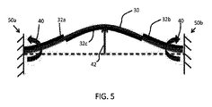
図5は、EAPアクチュエータ装置の第1の例を示す。 FIG. 5 shows a first example of an EAP actuator device.
この例は、電気活性ポリマー(EAP)の形態の活性層30を有する。活性層30は、対向する端部クランプ50a,50bの間に延びる。EAP層は、受動キャリア層32との相互作用の結果として拡張されたときに、屈曲する。キャリア層は、屈曲を所望の方向に制限する。キャリア層及び活性EAP層は共に、「作動装置又はさらにはEAP装置」と考えることができる。
This example has an
キャリア層は3つの部分を含む。第1及び第2の部分32a,32bは、EAP層の各端部において、クランプ50a,50bへの接続部にある。これら第1及び第2の部分は、EAP層30の上部にあり、EAP層が拡張すると、これらの部分32a,32bで上向きに屈曲する(上から見ると凸形状であり、下から見ると凹形状である)。第3の中央部分32cは、EAP層の中間部分の下にある。EAP層が拡張すると、この第3の部分が下向きに屈曲する(上方から見ると凹形状であり、下から見ると凸形状である)。従って、全体的な形状は、異なる領域で凹凸状になり、屈曲の方向を制御するために予備成形が用いられる。
The carrier layer includes three parts. The first and
このように、クランプの近くのキャリア層の位置が逆転され、それによりクランプの近くのモーメント40が、アクチュエータ端部の変位に対してではなく、アクチュエータ中央の変位42に作用する。結果として、アクチュエータ中央の変位42は、図4に示されるような受動キャリア層を片面に有するアクチュエータと比較して増大する。
In this way, the position of the carrier layer near the clamp is reversed so that the
最適な幾何学的形状及び改善係数は、モデリング及び/又はテストによって決定してもよい。EAP層及びキャリア層は、活性化されたときにEAPが拡張するので、キャリア層が常により短い曲線側になるように変形する。 The optimal geometry and improvement factor may be determined by modeling and / or testing. Since the EAP expands when activated, the EAP layer and the carrier layer always deform so that the carrier layer is on the shorter curved side.
有限要素シミュレーションが、様々な設計の実現可能性を評価するために実施された。活性層は、マクスウェル応力によって記述される電気機械力を含むNeo-Hookeanソリッドとしてモデル化される。使用されるデフォルト寸法及び特性は次の通りである。

ベースラインを設定するために、図3に示されるような従来の固定アクチュエータのシミュレーションを最初に実施した。得られた最大のたわみは0.284mmであり、最大力は0.25Nであった。 In order to set a baseline, a simulation of a conventional fixed actuator as shown in FIG. 3 was first performed. The maximum deflection obtained was 0.284 mm and the maximum force was 0.25N.
図6は、図5の構造の実装形態を示す。EAP層30及び3つの部分のキャリア層32a,32b,32cは、フレーム60に取り付けられる。端部は、棚部62に載置されており、リング又は接着剤64によって定位置にクランプされる。フレームの中央では、アクチュエータのたわみを所望の方向に案内するために、予備成形された小さな隆起部66が導入される。キャリア層部分は、位置67の各側で互いに重なり合う。これは、変位に大きな影響を及ぼさないが、これらの点における応力集中及び高せん断荷重の問題を回避する。
FIG. 6 shows an implementation of the structure of FIG. The
実行されたシミュレーションは、作動状態でのたわみが0.69mmであり、最大力が0.8Nであることを示した。力及びたわみの両方がベースラインの場合よりも高い。 The simulations performed showed that the deflection in the operating state was 0.69 mm and the maximum force was 0.8N. Both force and deflection are higher than at baseline.
予備成形された隆起部を使用する代わりに、予備成形は、クランプ50a,50bを互いに向けて移動させ、アクチュエータが初期曲率を有するようにすることによって達成される。これは、アクチュエータがその作動状態で耐え得る力の量を著しく増大させることができる。このようなバージョンの有限要素解析では、図6の例で得られたものよりも半分未満の0.33mmの有効たわみが示されているが、この場合の可能な最大負荷は2.92Nであり、図6の例で得られたものよりも数倍高い。
Instead of using a pre-formed ridge, pre-forming is accomplished by moving the
図7は別の例を示す。図6との違いは、クランプ50a,50bの直前でEAP層30が終了し、キャリア層の第1及び第2の部分32a,32bのみがクランプされることである。
FIG. 7 shows another example. The difference from FIG. 6 is that the
こうして、キャリア層のエッジ部分32a,32bは活性EAP層30を越えて延び、装置はこれらの伸長部を用いて固定される。
Thus, the
図8は、比較のために3つの可能な接続方式を示す。図8(a)は、クランプ同士の間に延びる活性EAP層のみを示す。図8(b)は、積み重ねられた活性EAP層及び受動キャリア層を示しており、両方の層がクランプされている。図8(c)は、上述したようなセグメント化されたキャリア層を含み、EAP層30のみが各端部にクランプされたアクチュエータを示す。
FIG. 8 shows three possible connection schemes for comparison. FIG. 8 (a) shows only the active EAP layer extending between the clamps. FIG. 8 (b) shows the stacked active EAP layer and passive carrier layer, both layers being clamped. FIG. 8 (c) shows an actuator that includes a segmented carrier layer as described above, with only the
各アクチュエータは、所望の方向へのたわみを確実にするためにこれに等しい量だけ最初に予備成形される。アクチュエータを撓ませるために電圧が印加され、その後、アクチュエータの中央に加えられる力は、アクチュエータがゼロ又はそれ以下のたわみに押し戻されるまで徐々に増大する。力−たわみ曲線を図9に示す。 Each actuator is initially preformed by an amount equal to this to ensure deflection in the desired direction. A voltage is applied to deflect the actuator, and then the force applied to the center of the actuator gradually increases until the actuator is pushed back to zero or less deflection. The force-deflection curve is shown in FIG.
活性EAP層のみを有する図8(a)のバージョンは、最大たわみを示すが、これはプロット80に示されるような力が制限される。図8(b)の積み重ねられたアクチュエータは、プロット82によって示されるように、たわみが減少する。図8(c)のアクチュエータは、活性層のバージョンよりも約30%少ないたわみをもたらすが、400%以上の力に耐えることができる。これはプロット84として示される。
The version of FIG. 8 (a) with only the active EAP layer shows maximum deflection, which limits the force as shown in
上記の例は、分割されたキャリア層を有する。代替案が図10に示されており、EAP層は、キャリア層の代わりに3つの部分に分割される。こうして、EAP層は、第1、第2、及び第3の部分30a,30b,30cを有する。第1及び第2の部分は、キャリア層32の下にあり、それら第1及び第2の部分は、クランプに接続するように端部にある。EAP層30cの中間の第3の部分は、キャリア層32の上にある。
The example above has a split carrier layer. An alternative is shown in FIG. 10, where the EAP layer is divided into three parts instead of the carrier layer. Thus, the EAP layer has first, second and
例えば、EAP層よりも強度を強くし得るキャリア層32は、次に、より強力なアクチュエータが製作可能となるように連続しており、特にEAP層よりも応力集中に敏感ではない。
For example, the
この実施形態の1つのバージョンの有限要素シミュレーションは、0.324mmのたわみ、及び約1.2Nの力を示す。これは、ベースラインと比較して、たわみの比較的小さな改善になるが、著しく高い力がもたらされ得る。 One version of the finite element simulation of this embodiment shows a deflection of 0.324 mm and a force of about 1.2 N. This results in a relatively small improvement in deflection compared to the baseline, but can result in significantly higher forces.
図11は、セグメント化されたEAP層30を使用する更なる例を示す。図10の例のように、第1、第2、及び第3の部分30a,30b,30cがある。また、中間部分及び/又はエッジ部分がさらにセグメント化される。この例は、3つの部分全てがさらにセグメント化されることを示す。いくつかの例では、曲げプロセスを制御するために、EAP層部分のセグメントを別々に起動してもよい。
FIG. 11 shows a further example using a
クランプに近い部分30a,30bのEAPセグメントが最初に起動され、続いてアクチュエータの中間部分のEAPセグメントが起動される。これにより、加えられる曲げの制御を改善することができる。しかしながら、この改良された制御は、アクチュエータのより小さい力及びより小さいストロークを犠牲にしている。
The EAP segments in the
従って、この作動方法は、電極の順次起動を利用する。アクチュエータを上向きに予め曲げるために、側部(30a及び30b)を最初に作動させて、中間部分(30c)を作動させるときに、更なる曲げが上向きに生じるようにすることができる。 This method of operation therefore utilizes sequential activation of the electrodes. In order to pre-bend the actuator upward, the sides (30a and 30b) can be actuated first so that further bending occurs when the intermediate part (30c) is actuated.
図12は、セグメント化されたキャリア30a,30b,30cと、連続したEAP層30上のセグメント化された電極とを組み合わせた更なる例を示す。
FIG. 12 shows a further example of combining
次に、EAP層30は、セグメント化された電極を個別にアドレス指定することによって局所的に作動させることができる。例えば、EAP層は、最初にエッジ部で局所的に起動され、続いてEAPの中間部分が起動される。
The
図13は、部分32a,32b,32cに形成されたキャリア層32を有する実装形態を示しており、この実装形態は、アクチュエータの変位を容易にさせるためにキャリア層の外面に形成されたチャネル90のアレイをさらに有する。これらは、曲げ半径がより小さくなる場合にエッジ部にのみ存在してもよく、又は図示されるように3つの部分全てに存在してもよい。キャリア層の曲がりは、チャネルを閉じる傾向があり、従って、チャネルは、チャネルが開いたままである間、キャリア層内の圧縮応力を少なくとも低減する。チャネルが閉じられると、アクチュエータの特定のたわみでロック機能が実施される。このように、チャネルが開いたままである間、キャリア層は曲げ易い。このアプローチは、上記の例のいずれにも適用できる。
FIG. 13 shows an implementation having a
上述したように、同じ構造をセンサとして使用してもよい。外部から誘発される圧縮は電場の変化を生じさせ、その結果、電極上に測定可能な信号が得られる。 As described above, the same structure may be used as a sensor. Externally induced compression causes a change in the electric field, resulting in a measurable signal on the electrode.
センサの場合に、連続的な構成では、応力の一部がセンサ信号を打ち消すので、例えば片側だけにバッキングを有する完全にクランプされたバイモルフセンサよりも、より強固でより感度の高い構造の利点がある。 In the case of sensors, the continuous configuration has the advantage of a stronger and more sensitive structure than a fully clamped bimorph sensor with a backing on only one side, for example, because some of the stress cancels the sensor signal. is there.
EAP装置全体は、例えば10mm×10mm×0.5mmの寸法を有してもよい。典型的で非限定的なサイズ範囲は、50mm×50mm×2mm〜2mm×2mm×0.1mmであってもよい。平面図の形状は正方形であってもよいが、細長い長方形又は円形であってもよい。円形の場合に、キャリア層のセグメント化された要素は同心円の形態をとる。 The entire EAP device may have dimensions of, for example, 10 mm × 10 mm × 0.5 mm. A typical non-limiting size range may be 50 mm × 50 mm × 2 mm to 2 mm × 2 mm × 0.1 mm. The shape of the plan view may be a square, but may be an elongated rectangle or a circle. In the circular case, the segmented elements of the carrier layer take the form of concentric circles.
上述した装置は、電極同士の間に挟まれた活性層を有し、電圧又は電流信号等の適切な電気的作動信号を電極に供給する。明瞭化のための電極は図示されていない。キャリア層は、(電界駆動型活性層の場合には)電極同士の間にも存在することができるが、電流駆動型活性層が必要又は使用されない場合もあり得る。 The device described above has an active layer sandwiched between electrodes and supplies an appropriate electrical actuation signal, such as a voltage or current signal, to the electrodes. The electrodes for clarity are not shown. The carrier layer can also be present between the electrodes (in the case of an electric field driven active layer), but the current driven active layer may not be necessary or used.
EAP層に適した材料は公知である。電気活性ポリマーには、サブクラス:圧電ポリマー、電気機械ポリマー、リラクサー強誘電性ポリマー、電歪ポリマー、誘電エラストマー、液晶エラストマー、共役ポリマー、イオン性ポリマー金属複合材料、イオン性ゲル、及びポリマーゲルが含まれるが、これらに限定されるものではない。 Suitable materials for the EAP layer are known. Electroactive polymers include subclasses: piezoelectric polymer, electromechanical polymer, relaxor ferroelectric polymer, electrostrictive polymer, dielectric elastomer, liquid crystal elastomer, conjugated polymer, ionic polymer metal composite, ionic gel, and polymer gel However, it is not limited to these.
サブクラスの電歪ポリマーには、ポリフッ化ビニリデン(PVDF)、ポリフッ化ビニリデン−トリフルオロエチレン(PVDF-TrFE)、ポリフッ化ビニリデン−トリフルオロエチレン−クロロフルオロエチレン(PVDF-TrFE-CFE)、ポリフッ化ビニリデン−トリフルオロエチレン−クロロトリフルオロエチレン(PVDF-TrFE-CTFE)、ポリフッ化ビニリデン−ヘキサフルオロプロピレン(PVDF-HFP)、ポリウレタン、又はこれらの混合物が含まれるが、これらに限定されるものではない。 Sub-class electrostrictive polymers include polyvinylidene fluoride (PVDF), polyvinylidene fluoride-trifluoroethylene (PVDF-TrFE), polyvinylidene fluoride-trifluoroethylene-chlorofluoroethylene (PVDF-TrFE-CFE), polyvinylidene fluoride -Includes, but is not limited to, trifluoroethylene-chlorotrifluoroethylene (PVDF-TrFE-CTFE), polyvinylidene fluoride-hexafluoropropylene (PVDF-HFP), polyurethane, or mixtures thereof.
サブクラスの誘電エラストマーには、アクリレート、ポリウレタン、シリコーンが含まれるが、これらに限定されるものではない。 Subclasses of dielectric elastomers include, but are not limited to, acrylates, polyurethanes, and silicones.
サブクラスの共役ポリマーには、ポリピロール、ポリ−3,4−エチレンジオキシチオフェン、ポリ(p−フェニレンスルフィド)、ポリアニリンが含まれるが、これらに限定されるものではない。 Subclasses of conjugated polymers include, but are not limited to, polypyrrole, poly-3,4-ethylenedioxythiophene, poly (p-phenylene sulfide), polyaniline.
印加された電界に応答してEAP層の挙動に影響を及ぼすために、追加の受動層を設けてもよい。 An additional passive layer may be provided to affect the behavior of the EAP layer in response to the applied electric field.
各ユニットのEAP層を電極同士の間に挟んでもよい。本発明が活性材料として誘電性エラストマーを使用する場合に、この層又は材料は、電極上の電圧信号により、電極によって材料が圧迫されるように、これらの電極同士の間に挟まれる。このような取り付けは、他の場合にも使用することができるが、圧電材料又は強誘電材料(リラクサー又は非リラクサー)等の場合に、必ずしも必要ではない。電極は、EPA材料層の変形に追従するように伸張可能であってもよい。電極に適した材料もまた公知であり、例えば、金、銅、又はアルミニウム等の金属薄膜、又はカーボンブラック、カーボンナノチューブ、グラフェン、ポリアニリン(PANI)、ポリ(3,4−エチレンジオキシチオフェン)PEDOT)、例えばポリ(3,4−エチレンジオキシチオフェン)ポリ(スチレンスルホネート)(PEDOT:PSS)等の有機導電体から構成されるグループから選択してもよい。例えばアルミニウムコーティングを使用する金属化されたポリエチレンテレフタレート(PET)等の金属化されたポリエステルフィルムを使用してもよい。 The EAP layer of each unit may be sandwiched between electrodes. When the present invention uses a dielectric elastomer as the active material, this layer or material is sandwiched between the electrodes so that the voltage signal on the electrodes compresses the material by the electrodes. Such attachment can be used in other cases, but is not necessarily required in the case of piezoelectric materials or ferroelectric materials (relaxers or non-relaxers) or the like. The electrode may be stretchable to follow the deformation of the EPA material layer. Suitable materials for the electrodes are also known, for example, metal thin films such as gold, copper, or aluminum, or carbon black, carbon nanotubes, graphene, polyaniline (PANI), poly (3,4-ethylenedioxythiophene) PEDOT For example, poly (3,4-ethylenedioxythiophene) poly (styrene sulfonate) (PEDOT: PSS). For example, a metallized polyester film such as metallized polyethylene terephthalate (PET) using an aluminum coating may be used.
異なる層の材料は、例えば異なる層の弾性率(ヤング率)を考慮して選択される。 The material of different layers is selected in consideration of, for example, the elastic modulus (Young's modulus) of the different layers.
上記の構成に追加の層を使用して、追加のポリマー層等の、装置の電気的又は機械的挙動を適合してもよい。 Additional layers may be used in the above configuration to adapt the electrical or mechanical behavior of the device, such as additional polymer layers.
EAP装置は、電界駆動型装置又はイオン性装置であってもよい。イオン性装置は、イオン性ポリマー−金属複合材料(IPMC)又は共役ポリマーをベースとすることができる。イオン性ポリマー−金属複合材料(IPMC)は、印加された電圧又は電場の下で人工筋肉の挙動を示す合成複合ナノ材料である。 The EAP device may be an electric field driven device or an ionic device. The ionic device can be based on an ionic polymer-metal composite (IPMC) or a conjugated polymer. An ionic polymer-metal composite (IPMC) is a synthetic composite nanomaterial that exhibits the behavior of artificial muscles under an applied voltage or electric field.
IPMCは、表面が、化学的にメッキされているか、又は白金又は金等の導体又は炭素系電極で物理的に被覆されているNafion又はFlemion等のイオン性ポリマーから構成される。印加された電圧の下で、IPMCのストリップ全体に課された電圧によるイオンの移動及び再分配は、曲げ変形を生じさせる。ポリマーは、溶媒膨潤したイオン交換ポリマー膜である。この電界により、陽イオンは水と共に陰極側に移動する。これは、親水性クラスターの再構成及びポリマー膨張につながる。陰極領域のひずみはポリマーマトリックスの残りの部分に応力をもたらし、陽極に向けて屈曲する。印加電圧を逆にすると屈曲が逆転する。 IPMC is composed of an ionic polymer such as Nafion or Flemion whose surface is chemically plated or physically coated with a conductor such as platinum or gold or a carbon-based electrode. Under the applied voltage, the movement and redistribution of ions due to the voltage imposed on the entire strip of IPMC causes bending deformation. The polymer is a solvent swelled ion exchange polymer membrane. By this electric field, cations move to the cathode side together with water. This leads to hydrophilic cluster reorganization and polymer expansion. The strain in the cathode region causes stress in the rest of the polymer matrix and bends towards the anode. When the applied voltage is reversed, the bending is reversed.
メッキされた電極が非対称構成で配置される場合に、課された電圧は、よじれ、回転、ねじれ、旋回、及び非対称曲げ変形等のあらゆる種類の変形を誘発する可能性がある。 When the plated electrodes are arranged in an asymmetric configuration, the imposed voltage can induce all kinds of deformations such as kinking, rotation, twisting, swiveling, and asymmetric bending deformation.
上述したように、上述した機械的設計は、光活性材料にも適用することができる。そのような光−機械的に応答する材料は、例えば、ポリマーマトリックスに埋め込まれた光−機械応答性分子から構成される。光−機械応答性分子は、特定の波長の光による照射の関数として形状を変化させる。 As mentioned above, the mechanical design described above can also be applied to photoactive materials. Such photo-mechanically responsive materials are composed, for example, of photo-mechanical responsive molecules embedded in a polymer matrix. Photo-mechanically responsive molecules change shape as a function of irradiation with light of a specific wavelength.
最も一般的な光機械材料は、材料中に存在する光応答性分子の2つの異性体状態同士の間の形状変化によって駆動される。トランス配置間のスイッチは、トランス状態の分子の吸収波長に対応する光で照明することによって駆動されるが、準安定シス形態へのスイッチバックは、熱的に誘発され得るか、又は、そのシス状態の分子の吸収波長に対応する波長の光で照射することによって再びトリガされ得る。 The most common optomechanical materials are driven by a shape change between the two isomeric states of the photoresponsive molecules present in the material. The switch between the transformer configurations is driven by illuminating with light corresponding to the absorption wavelength of the molecules in the transformer state, but switchback to the metastable cis form can be thermally induced or the cis It can be triggered again by irradiating with light of a wavelength corresponding to the absorption wavelength of the molecule in the state.
そのような材料には、アントラセン、ジアリールエテン、スピロピラン、及びアゾベンゼン(アミノアゾベンゼン及び擬スチルベン等の置換型アゾベンゼンを含む)が含まれるが、これらに限定されるものではない。これらの光−機械応答性分子は、そのような官能性光−機械反応性分子によるホストポリマーのドーピング又は重合によるポリマー中の光−機械的官能基を有する共有結合分子を介して、ポリマー材料中に埋め込まれる。これには、アゾ官能化モノマーの重合、又は異なる主鎖を有するポリマーの官能化後に、側鎖アゾ官能化ポリマーを生成することが含まれる。 Such materials include, but are not limited to, anthracene, diarylethene, spiropyran, and azobenzene (including substituted azobenzenes such as aminoazobenzene and pseudostilbene). These photo-mechanically responsive molecules are incorporated into the polymer material via covalent molecules having photo-mechanical functional groups in the polymer by doping or polymerization of the host polymer with such functional photo-mechanically reactive molecules. Embedded in. This includes producing side chain azo functionalized polymers after polymerization of azo functionalized monomers or functionalization of polymers with different backbones.
ポリマーは、性質上、アモルファス又は液晶(LC)となり得る。アモルファスポリマーが全ての方向に均等に収縮する場合に、LCポリマーを優先方向に変形させることができ、その方向の効果を大幅に増大させることができる。液晶エラストマー(LCE)は、全て固体状態のポリマー材料においてLCによって誘導される方向性を有することができるので、光−機械材料に特に適した材料である。 The polymer can be amorphous or liquid crystal (LC) in nature. If the amorphous polymer shrinks evenly in all directions, the LC polymer can be deformed in the preferred direction and the effect in that direction can be greatly increased. Liquid crystal elastomers (LCE) are particularly suitable materials for opto-mechanical materials because they can have LC-induced orientation in all solid state polymer materials.
本発明は、アクチュエータの受動マトリクスアレイが重要である例を含む、多くのEAP及び光活性ポリマー用途に適用することができる。 The present invention can be applied to many EAP and photoactive polymer applications, including examples where a passive matrix array of actuators is important.
多くの用途において、製品の主な機能は、ヒト組織の(局所的な)操作又は組織の接触界面の作動に依拠する。そのような用途では、EAPアクチュエータは、例えば、小型のフォームファクタ、柔軟性、及び高いエネルギー密度のために、主に特有の利点を提供する。こうして、EAP及び光活性ポリマーは、ソフトな、3D形状及び/又は小型製品、及びインターフェースに容易に統合することができる。そのような用途の例は以下の通りである:
皮膚を緊張させる又はしわを減らすために、皮膚に一定の又は周期的なストレッチを適用する、応答性ポリマーベースの皮膚パッチの形態の皮膚作動装置等の皮膚美容処置;
交互の正常な圧力を皮膚に与えて顔面の赤いあざを低減又は防止する、反応性ポリマーベースの活性クッション又はシールを有する患者インターフェイスマスクを有する呼吸装置;
適応シェービングヘッドを有する電気シェーバー。近接性と炎症との間のバランスに影響を与えるために、反応性ポリマーアクチュエータを使用して、皮膚接触面の高さを調節することができる;
特に歯と歯との間の空間においてスプレーの到達範囲を改善するための動的ノズルアクチュエータを有するエアーフロス等の口腔洗浄装置。代替的に、活性化したタフトが設けられた歯ブラシ;
ユーザインタフェース内に又はその近くに統合された応答性ポリマートランスデューサのアレイを介して局所的な触覚フィードバックを提供する家電装置又はタッチパネル;
蛇行する血管内での容易なナビゲーションを可能にするための操縦可能なチップを有するカテーテル;である。
In many applications, the main function of the product relies on the manipulation of human tissue (local) or the tissue contact interface. In such applications, EAP actuators offer primarily unique advantages, for example, due to their small form factor, flexibility, and high energy density. Thus, EAP and photoactive polymers can be easily integrated into soft 3D shapes and / or small products and interfaces. Examples of such applications are as follows:
Skin cosmetic procedures, such as skin actuators in the form of responsive polymer-based skin patches, that apply a constant or periodic stretch to the skin to tension or reduce wrinkles;
A respiratory apparatus having a patient interface mask with a reactive polymer-based active cushion or seal that applies alternating normal pressure to the skin to reduce or prevent red bruises on the face;
Electric shaver with adaptive shaving head. Reactive polymer actuators can be used to adjust the height of the skin contact surface to affect the balance between proximity and inflammation;
An oral cleaning device such as an air floss having a dynamic nozzle actuator for improving the spray reach, particularly in the space between teeth. Alternatively, a toothbrush provided with an activated tuft;
A consumer electronics device or touch panel that provides local haptic feedback via an array of responsive polymer transducers integrated in or near the user interface;
A catheter having a steerable tip to allow easy navigation within a tortuous vessel.
そのようなアクチュエータから利益を受ける関連する用途の別のカテゴリは、光の調節に関する。レンズ、反射面、回折格子等の光学素子は、これらのアクチュエータを使用する形状又は位置適合によって適応可能にすることができる。例えば、EAPの1つの利点は、より低い消費電力である。 Another category of related applications that benefit from such actuators relates to light regulation. Optical elements such as lenses, reflective surfaces, diffraction gratings, etc. can be made adaptable by shape or position adaptation using these actuators. For example, one advantage of EAP is lower power consumption.
開示された実施形態に対する他の変形形態は、図面、明細書の開示、及び添付の特許請求の範囲の検討から特許請求の範囲に記載された発明を実施する際に当業者によって理解され、達成され得る。特許請求の範囲において、「備える、有する、含む(comprising)」という単語は、他の要素又はステップを排除するものではなく、不定冠詞「1つの(a,an)」は、複数を除外するものではない。特定の手段が互いに異なる従属請求項に列挙されているという単なる事実は、これらの手段の組合せが有利に使用できないことを示すものではない。特許請求の範囲内のいかなる参照符号も、特許請求の範囲を限定するものとして解釈すべきではない。 Other variations to the disclosed embodiments will be understood and attained by those skilled in the art in practicing the claimed invention from a study of the drawings, the disclosure of the specification, and the appended claims. Can be done. In the claims, the word “comprising” does not exclude other elements or steps, and the indefinite article “a, an” excludes a plurality. is not. The mere fact that certain measures are recited in mutually different dependent claims does not indicate that a combination of these measured cannot be used to advantage. Any reference signs in the claims should not be construed as limiting the claim.
Claims (15)
固定された両端部の間に延びる作動装置を有しており、
該作動装置は、
電気活性ポリマー及び/又は光活性ポリマーを含む活性層と、
受動キャリア層と、を含む層スタックを有しており、
前記固定された両端部の少なくとも一方において又はこれに隣接して、前記キャリア層及び前記活性層は、第1の順序で一方が他方の上に取り付けられ、前記固定された両端部の間の中間領域において、前記キャリア層及び前記活性層は、第1の順序とは反対の第2の順序で他方が一方の上に取り付けられる、
装置。 An actuator and / or sensor device, the device comprising:
Having an actuating device extending between the fixed ends,
The actuator is
An active layer comprising an electroactive polymer and / or a photoactive polymer;
A layer stack comprising a passive carrier layer, and
At least one of the fixed ends, or adjacent thereto, the carrier layer and the active layer are attached one over the other in a first order, and intermediate between the fixed ends. In the region, the carrier layer and the active layer are attached on one another in a second order opposite to the first order,
apparatus.
前記作動装置は、前記中間領域において、前記ベースに対して上向きに屈曲するように適合され、
前記キャリア層は、前記固定された両端部の少なくとも一方において又はこれに隣接して前記活性層の上にあり、前記活性層は、前記中間領域において前記キャリア層の上にある、請求項1に記載の装置。 Have a base,
The actuating device is adapted to bend upwards relative to the base in the intermediate region;
The carrier layer is on the active layer at or adjacent to at least one of the fixed ends, and the active layer is on the carrier layer in the intermediate region. The device described.
当該装置が前記作動装置を作動させるための複数の電極を含む場合に、前記複数の電極は、前記作動装置の異なる部分を独立して作動させることができるように分布されており、又は、
当該装置が光学装置を含む場合に、前記作動装置の異なる部分を独立して作動させることができる、ように構成されている、請求項10乃至13のいずれか一項に記載の装置。 The device is
If the device includes a plurality of electrodes for actuating the actuating device, the plurality of electrodes are distributed such that different parts of the actuating device can be actuated independently; or
14. Apparatus according to any one of claims 10 to 13 , configured so that different parts of the actuating device can be actuated independently when the device comprises an optical device.
Applications Claiming Priority (3)
| Application Number | Priority Date | Filing Date | Title |
|---|---|---|---|
| EP15183165 | 2015-08-31 | ||
| EP15183165.8 | 2015-08-31 | ||
| PCT/EP2016/069679 WO2017036815A1 (en) | 2015-08-31 | 2016-08-19 | Actuator or sensor device based on an electroactive or photoactive polymer |
Publications (2)
| Publication Number | Publication Date |
|---|---|
| JP2018533335A JP2018533335A (en) | 2018-11-08 |
| JP6457151B2 true JP6457151B2 (en) | 2019-01-23 |
Family
ID=54072671
Family Applications (1)
| Application Number | Title | Priority Date | Filing Date |
|---|---|---|---|
| JP2018510357A Active JP6457151B2 (en) | 2015-08-31 | 2016-08-19 | Actuators or sensor devices based on electroactive or photoactive polymers |
Country Status (7)
| Country | Link |
|---|---|
| US (1) | US11211544B2 (en) |
| EP (1) | EP3344872B1 (en) |
| JP (1) | JP6457151B2 (en) |
| CN (1) | CN107923371B (en) |
| BR (1) | BR112018003586A2 (en) |
| RU (1) | RU2727067C2 (en) |
| WO (1) | WO2017036815A1 (en) |
Families Citing this family (11)
| Publication number | Priority date | Publication date | Assignee | Title |
|---|---|---|---|---|
| US11231544B2 (en) | 2015-11-06 | 2022-01-25 | Magic Leap, Inc. | Metasurfaces for redirecting light and methods for fabricating |
| AU2017260208B2 (en) | 2016-05-06 | 2021-09-23 | Magic Leap, Inc. | Metasurfaces with asymetric gratings for redirecting light and methods for fabricating |
| EP3472874B1 (en) * | 2016-06-20 | 2019-10-09 | Koninklijke Philips N.V. | Friction control device and method |
| WO2018140502A1 (en) | 2017-01-27 | 2018-08-02 | Magic Leap, Inc. | Antireflection coatings for metasurfaces |
| CN109756147B (en) * | 2018-12-13 | 2020-03-31 | 西安交通大学 | Electric actuating inchworm bionic structure based on liquid crystal elastic polymer and manufacturing process |
| CN109921679B (en) * | 2019-03-08 | 2020-03-10 | 吉林大学 | Bionic flexible actuator with real-time feedback function and preparation method thereof |
| ES2902432T3 (en) * | 2019-04-02 | 2022-03-28 | Airbus Operations Gmbh | Panels for the cabin of an aircraft |
| US11411166B2 (en) | 2019-05-17 | 2022-08-09 | International Business Machines Corporation | Conductive particle interconnect switch |
| US11411165B2 (en) | 2019-05-17 | 2022-08-09 | International Business Machines Corporation | Conductive particle interconnect switch |
| CN110919631A (en) * | 2019-11-19 | 2020-03-27 | 西安理工大学 | Rigid-flexible composite robot based on dielectric elastomer minimum energy structure |
| CN114833831B (en) * | 2022-05-09 | 2023-06-06 | 西湖大学 | Method, system and application for driving artificial muscle to automatically and continuously fluctuate |
Family Cites Families (26)
| Publication number | Priority date | Publication date | Assignee | Title |
|---|---|---|---|---|
| JPH03171784A (en) | 1989-11-30 | 1991-07-25 | Toshiba Corp | Bimorph element |
| US6781285B1 (en) | 1994-01-27 | 2004-08-24 | Cymer, Inc. | Packaged strain actuator |
| EP1221180B1 (en) * | 1999-07-20 | 2010-09-08 | SRI International | Electroactive polymers |
| EP1212800B1 (en) * | 1999-07-20 | 2007-12-12 | Sri International | Electroactive polymer generators |
| GB0126372D0 (en) * | 2001-11-02 | 2002-01-02 | 1 Ltd | Curved electro-active actuators |
| US8398693B2 (en) | 2004-01-23 | 2013-03-19 | Boston Scientific Scimed, Inc. | Electrically actuated medical devices |
| US7575807B1 (en) * | 2004-05-28 | 2009-08-18 | Hrl Laboratories, Llc | Hybrid active deformable material structure |
| JP4732876B2 (en) * | 2005-11-30 | 2011-07-27 | 株式会社日立製作所 | Actuator, actuator module, and actuator module manufacturing method |
| WO2007092386A2 (en) * | 2006-02-06 | 2007-08-16 | Energy Related Devices, Inc. | Laminate actuators and valves |
| EP2178700A2 (en) * | 2006-02-07 | 2010-04-28 | MicroMuscle AB | Electroactive polymer actuators, applications and methods for fabrication thereof |
| US7951186B2 (en) | 2006-04-25 | 2011-05-31 | Boston Scientific Scimed, Inc. | Embedded electroactive polymer structures for use in medical devices |
| DE112007003042B4 (en) | 2006-12-27 | 2011-11-03 | Murata Manufacturing Co., Ltd. | Piezoelectric valve |
| JP5123532B2 (en) | 2007-01-30 | 2013-01-23 | 太陽誘電株式会社 | Micro cantilever |
| JP2009303325A (en) * | 2008-06-11 | 2009-12-24 | Alps Electric Co Ltd | Polymeric actuator |
| EP2133306A1 (en) * | 2008-06-13 | 2009-12-16 | Stichting Dutch Polymer Institute | Polymer micro-actuators sensitive to one or more inputs |
| US8222799B2 (en) | 2008-11-05 | 2012-07-17 | Bayer Materialscience Ag | Surface deformation electroactive polymer transducers |
| US7948151B1 (en) | 2009-04-09 | 2011-05-24 | The United States Of America As Represented By The Secretary Of The Navy | Electroactive polymer-based artificial neuromuscular unit |
| JP2011054615A (en) | 2009-08-31 | 2011-03-17 | Murata Mfg Co Ltd | Actuator |
| FR2950153B1 (en) * | 2009-09-15 | 2011-12-23 | Commissariat Energie Atomique | OPTICAL DEVICE WITH DEFORMABLE MEMBRANE WITH PIEZOELECTRIC ACTUATION |
| JP5959807B2 (en) | 2010-08-05 | 2016-08-02 | キヤノン株式会社 | Actuator and actuator structure |
| JP5893625B2 (en) | 2010-09-09 | 2016-03-23 | コーニンクレッカ フィリップス エヌ ヴェKoninklijke Philips N.V. | Electroactive polymer actuator |
| IT1402181B1 (en) | 2010-09-13 | 2013-08-28 | Fond Istituto Italiano Di Tecnologia | ELECTRO-ACTIVE MICROELETTROMECHANICAL DEVICE AND RELATIVE DETECTION PROCEDURE |
| KR101703281B1 (en) * | 2010-12-07 | 2017-02-06 | 삼성전자주식회사 | Multilayered electro-active polymer device and method for fabricating the same |
| JP6797835B2 (en) * | 2015-06-03 | 2020-12-09 | コーニンクレッカ フィリップス エヌ ヴェKoninklijke Philips N.V. | Activator |
| US10777730B2 (en) * | 2017-12-26 | 2020-09-15 | Santosh Kumar BEHERA | Scalable piezoelectric linear actuator |
| DE102018206665A1 (en) * | 2018-04-30 | 2019-10-31 | Airbus Operations Gmbh | Structural component and system and method for the detection of damage |
-
2016
- 2016-08-19 CN CN201680050133.7A patent/CN107923371B/en active Active
- 2016-08-19 US US15/752,748 patent/US11211544B2/en active Active
- 2016-08-19 BR BR112018003586A patent/BR112018003586A2/en not_active Application Discontinuation
- 2016-08-19 RU RU2018107040A patent/RU2727067C2/en active
- 2016-08-19 JP JP2018510357A patent/JP6457151B2/en active Active
- 2016-08-19 EP EP16758117.2A patent/EP3344872B1/en active Active
- 2016-08-19 WO PCT/EP2016/069679 patent/WO2017036815A1/en active Application Filing
Also Published As
| Publication number | Publication date |
|---|---|
| US11211544B2 (en) | 2021-12-28 |
| RU2018107040A3 (en) | 2019-12-24 |
| RU2018107040A (en) | 2019-10-04 |
| EP3344872B1 (en) | 2019-06-19 |
| RU2727067C2 (en) | 2020-07-17 |
| EP3344872A1 (en) | 2018-07-11 |
| JP2018533335A (en) | 2018-11-08 |
| US20180254404A1 (en) | 2018-09-06 |
| WO2017036815A1 (en) | 2017-03-09 |
| BR112018003586A2 (en) | 2018-09-25 |
| CN107923371B (en) | 2020-03-31 |
| CN107923371A (en) | 2018-04-17 |
Similar Documents
| Publication | Publication Date | Title |
|---|---|---|
| JP6457151B2 (en) | Actuators or sensor devices based on electroactive or photoactive polymers | |
| CN107431121B (en) | Electroactive polymer-based actuator or sensor device | |
| JP6464317B2 (en) | Actuator devices based on electroactive or photoactive polymers | |
| JP6797835B2 (en) | Activator | |
| JP7036753B2 (en) | Shape deformer | |
| US10892690B2 (en) | Actuator device and array of the same | |
| US20210336122A1 (en) | Actuator device based on an electroactive material | |
| JP2019521521A (en) | Friction control device and method |
Legal Events
| Date | Code | Title | Description |
|---|---|---|---|
| A521 | Request for written amendment filed |
Free format text: JAPANESE INTERMEDIATE CODE: A523 Effective date: 20180828 |
|
| TRDD | Decision of grant or rejection written | ||
| A01 | Written decision to grant a patent or to grant a registration (utility model) |
Free format text: JAPANESE INTERMEDIATE CODE: A01 Effective date: 20181120 |
|
| A61 | First payment of annual fees (during grant procedure) |
Free format text: JAPANESE INTERMEDIATE CODE: A61 Effective date: 20181219 |
|
| R150 | Certificate of patent or registration of utility model |
Ref document number: 6457151 Country of ref document: JP Free format text: JAPANESE INTERMEDIATE CODE: R150 |
|
| R250 | Receipt of annual fees |
Free format text: JAPANESE INTERMEDIATE CODE: R250 |
|
| R250 | Receipt of annual fees |
Free format text: JAPANESE INTERMEDIATE CODE: R250 |