JP6446239B2 - Secondary battery - Google Patents
Secondary battery Download PDFInfo
- Publication number
- JP6446239B2 JP6446239B2 JP2014223282A JP2014223282A JP6446239B2 JP 6446239 B2 JP6446239 B2 JP 6446239B2 JP 2014223282 A JP2014223282 A JP 2014223282A JP 2014223282 A JP2014223282 A JP 2014223282A JP 6446239 B2 JP6446239 B2 JP 6446239B2
- Authority
- JP
- Japan
- Prior art keywords
- gasket
- battery
- external terminal
- compression
- secondary battery
- Prior art date
- Legal status (The legal status is an assumption and is not a legal conclusion. Google has not performed a legal analysis and makes no representation as to the accuracy of the status listed.)
- Active
Links
- 230000006835 compression Effects 0.000 claims description 90
- 238000007906 compression Methods 0.000 claims description 90
- 238000007789 sealing Methods 0.000 claims description 78
- 239000003792 electrolyte Substances 0.000 claims description 9
- 239000011888 foil Substances 0.000 description 26
- 239000000203 mixture Substances 0.000 description 19
- HBBGRARXTFLTSG-UHFFFAOYSA-N Lithium ion Chemical compound [Li+] HBBGRARXTFLTSG-UHFFFAOYSA-N 0.000 description 8
- 229910001416 lithium ion Inorganic materials 0.000 description 8
- 238000004804 winding Methods 0.000 description 8
- 239000007773 negative electrode material Substances 0.000 description 7
- 239000007774 positive electrode material Substances 0.000 description 7
- 238000003466 welding Methods 0.000 description 7
- 239000011230 binding agent Substances 0.000 description 6
- 238000002347 injection Methods 0.000 description 5
- 239000007924 injection Substances 0.000 description 5
- 239000007788 liquid Substances 0.000 description 5
- -1 polybutylene terephthalate Polymers 0.000 description 5
- 239000002033 PVDF binder Substances 0.000 description 4
- 229910052782 aluminium Inorganic materials 0.000 description 4
- XAGFODPZIPBFFR-UHFFFAOYSA-N aluminium Chemical compound [Al] XAGFODPZIPBFFR-UHFFFAOYSA-N 0.000 description 4
- 239000011324 bead Substances 0.000 description 4
- 239000006185 dispersion Substances 0.000 description 4
- 239000008151 electrolyte solution Substances 0.000 description 4
- 229920002981 polyvinylidene fluoride Polymers 0.000 description 4
- 239000002904 solvent Substances 0.000 description 4
- 229910000838 Al alloy Inorganic materials 0.000 description 3
- RYGMFSIKBFXOCR-UHFFFAOYSA-N Copper Chemical compound [Cu] RYGMFSIKBFXOCR-UHFFFAOYSA-N 0.000 description 3
- SECXISVLQFMRJM-UHFFFAOYSA-N N-Methylpyrrolidone Chemical compound CN1CCCC1=O SECXISVLQFMRJM-UHFFFAOYSA-N 0.000 description 3
- QHGJSLXSVXVKHZ-UHFFFAOYSA-N dilithium;dioxido(dioxo)manganese Chemical compound [Li+].[Li+].[O-][Mn]([O-])(=O)=O QHGJSLXSVXVKHZ-UHFFFAOYSA-N 0.000 description 3
- 230000000694 effects Effects 0.000 description 3
- 230000005489 elastic deformation Effects 0.000 description 3
- 229910052744 lithium Inorganic materials 0.000 description 3
- 239000000463 material Substances 0.000 description 3
- OKTJSMMVPCPJKN-UHFFFAOYSA-N Carbon Chemical compound [C] OKTJSMMVPCPJKN-UHFFFAOYSA-N 0.000 description 2
- 229910000881 Cu alloy Inorganic materials 0.000 description 2
- WHXSMMKQMYFTQS-UHFFFAOYSA-N Lithium Chemical compound [Li] WHXSMMKQMYFTQS-UHFFFAOYSA-N 0.000 description 2
- 229910003481 amorphous carbon Inorganic materials 0.000 description 2
- 239000002131 composite material Substances 0.000 description 2
- 239000004020 conductor Substances 0.000 description 2
- 229910052802 copper Inorganic materials 0.000 description 2
- 239000010949 copper Substances 0.000 description 2
- 239000013078 crystal Substances 0.000 description 2
- 238000005520 cutting process Methods 0.000 description 2
- 238000001035 drying Methods 0.000 description 2
- 238000005242 forging Methods 0.000 description 2
- 229910052751 metal Inorganic materials 0.000 description 2
- 239000002184 metal Substances 0.000 description 2
- 238000000034 method Methods 0.000 description 2
- 239000002245 particle Substances 0.000 description 2
- 229920001343 polytetrafluoroethylene Polymers 0.000 description 2
- 239000004810 polytetrafluoroethylene Substances 0.000 description 2
- 238000003825 pressing Methods 0.000 description 2
- 229920005989 resin Polymers 0.000 description 2
- 239000011347 resin Substances 0.000 description 2
- BQCIDUSAKPWEOX-UHFFFAOYSA-N 1,1-Difluoroethene Chemical compound FC(F)=C BQCIDUSAKPWEOX-UHFFFAOYSA-N 0.000 description 1
- OFHQVNFSKOBBGG-UHFFFAOYSA-N 1,2-difluoropropane Chemical compound CC(F)CF OFHQVNFSKOBBGG-UHFFFAOYSA-N 0.000 description 1
- KXJGSNRAQWDDJT-UHFFFAOYSA-N 1-acetyl-5-bromo-2h-indol-3-one Chemical compound BrC1=CC=C2N(C(=O)C)CC(=O)C2=C1 KXJGSNRAQWDDJT-UHFFFAOYSA-N 0.000 description 1
- 239000004925 Acrylic resin Substances 0.000 description 1
- 229920000178 Acrylic resin Polymers 0.000 description 1
- NLHHRLWOUZZQLW-UHFFFAOYSA-N Acrylonitrile Chemical compound C=CC#N NLHHRLWOUZZQLW-UHFFFAOYSA-N 0.000 description 1
- KMTRUDSVKNLOMY-UHFFFAOYSA-N Ethylene carbonate Chemical compound O=C1OCCO1 KMTRUDSVKNLOMY-UHFFFAOYSA-N 0.000 description 1
- KRHYYFGTRYWZRS-UHFFFAOYSA-M Fluoride anion Chemical compound [F-] KRHYYFGTRYWZRS-UHFFFAOYSA-M 0.000 description 1
- 229910015643 LiMn 2 O 4 Inorganic materials 0.000 description 1
- 229910013870 LiPF 6 Inorganic materials 0.000 description 1
- 229920000459 Nitrile rubber Polymers 0.000 description 1
- 239000000020 Nitrocellulose Substances 0.000 description 1
- 229920001774 Perfluoroether Polymers 0.000 description 1
- 239000005062 Polybutadiene Substances 0.000 description 1
- 239000004698 Polyethylene Substances 0.000 description 1
- 239000004734 Polyphenylene sulfide Substances 0.000 description 1
- 239000004743 Polypropylene Substances 0.000 description 1
- 239000004793 Polystyrene Substances 0.000 description 1
- 229910008484 TiSi Inorganic materials 0.000 description 1
- RTAQQCXQSZGOHL-UHFFFAOYSA-N Titanium Chemical compound [Ti] RTAQQCXQSZGOHL-UHFFFAOYSA-N 0.000 description 1
- KLARSDUHONHPRF-UHFFFAOYSA-N [Li].[Mn] Chemical compound [Li].[Mn] KLARSDUHONHPRF-UHFFFAOYSA-N 0.000 description 1
- 229910021383 artificial graphite Inorganic materials 0.000 description 1
- 229920005549 butyl rubber Polymers 0.000 description 1
- 239000003575 carbonaceous material Substances 0.000 description 1
- YACLQRRMGMJLJV-UHFFFAOYSA-N chloroprene Chemical compound ClC(=C)C=C YACLQRRMGMJLJV-UHFFFAOYSA-N 0.000 description 1
- 239000000571 coke Substances 0.000 description 1
- 150000001875 compounds Chemical class 0.000 description 1
- 239000011889 copper foil Substances 0.000 description 1
- 238000013461 design Methods 0.000 description 1
- 238000011161 development Methods 0.000 description 1
- IEJIGPNLZYLLBP-UHFFFAOYSA-N dimethyl carbonate Chemical compound COC(=O)OC IEJIGPNLZYLLBP-UHFFFAOYSA-N 0.000 description 1
- 229920001971 elastomer Polymers 0.000 description 1
- 239000000835 fiber Substances 0.000 description 1
- XUCNUKMRBVNAPB-UHFFFAOYSA-N fluoroethene Chemical compound FC=C XUCNUKMRBVNAPB-UHFFFAOYSA-N 0.000 description 1
- 229910002804 graphite Inorganic materials 0.000 description 1
- 239000010439 graphite Substances 0.000 description 1
- 239000007770 graphite material Substances 0.000 description 1
- 238000007373 indentation Methods 0.000 description 1
- 238000003780 insertion Methods 0.000 description 1
- 230000037431 insertion Effects 0.000 description 1
- 238000004519 manufacturing process Methods 0.000 description 1
- 239000002905 metal composite material Substances 0.000 description 1
- 239000007769 metal material Substances 0.000 description 1
- 239000011259 mixed solution Substances 0.000 description 1
- 229910021382 natural graphite Inorganic materials 0.000 description 1
- 229920001220 nitrocellulos Polymers 0.000 description 1
- 239000011255 nonaqueous electrolyte Substances 0.000 description 1
- 230000002093 peripheral effect Effects 0.000 description 1
- 229920002857 polybutadiene Polymers 0.000 description 1
- 229920001707 polybutylene terephthalate Polymers 0.000 description 1
- 229920000573 polyethylene Polymers 0.000 description 1
- 229920013716 polyethylene resin Polymers 0.000 description 1
- 229920000642 polymer Polymers 0.000 description 1
- 229920000069 polyphenylene sulfide Polymers 0.000 description 1
- 229920001155 polypropylene Polymers 0.000 description 1
- 229920002223 polystyrene Polymers 0.000 description 1
- 239000005077 polysulfide Substances 0.000 description 1
- 229920001021 polysulfide Polymers 0.000 description 1
- 150000008117 polysulfides Polymers 0.000 description 1
- 238000012545 processing Methods 0.000 description 1
- 230000002250 progressing effect Effects 0.000 description 1
- 230000001681 protective effect Effects 0.000 description 1
- 238000011160 research Methods 0.000 description 1
- 239000005060 rubber Substances 0.000 description 1
- 229910052596 spinel Inorganic materials 0.000 description 1
- 239000011029 spinel Substances 0.000 description 1
- 229920003048 styrene butadiene rubber Polymers 0.000 description 1
- 239000000126 substance Substances 0.000 description 1
- 229920003002 synthetic resin Polymers 0.000 description 1
- 239000000057 synthetic resin Substances 0.000 description 1
- 229910052718 tin Inorganic materials 0.000 description 1
Images


Classifications
-
- Y—GENERAL TAGGING OF NEW TECHNOLOGICAL DEVELOPMENTS; GENERAL TAGGING OF CROSS-SECTIONAL TECHNOLOGIES SPANNING OVER SEVERAL SECTIONS OF THE IPC; TECHNICAL SUBJECTS COVERED BY FORMER USPC CROSS-REFERENCE ART COLLECTIONS [XRACs] AND DIGESTS
- Y02—TECHNOLOGIES OR APPLICATIONS FOR MITIGATION OR ADAPTATION AGAINST CLIMATE CHANGE
- Y02E—REDUCTION OF GREENHOUSE GAS [GHG] EMISSIONS, RELATED TO ENERGY GENERATION, TRANSMISSION OR DISTRIBUTION
- Y02E60/00—Enabling technologies; Technologies with a potential or indirect contribution to GHG emissions mitigation
- Y02E60/10—Energy storage using batteries
Description
本発明は、車載用途等に使用される二次電池に関する。 The present invention relates to a secondary battery used for in-vehicle use.
従来から、例えば、電気自動車やハイブリッド電気自動車等の車両に搭載された電気モーター等に電力を供給する車載用電源又はその他の機器の電源として、二次電池が用いられている。このような二次電池として、高エネルギー密度を有するリチウムイオン二次電池が着目され、その研究、開発及び商品化が急速に進められている。リチウムイオン二次電池では、電池の内部のガスや電解液に対する密閉性が要求される。 Conventionally, for example, a secondary battery has been used as an in-vehicle power source for supplying electric power to an electric motor or the like mounted on a vehicle such as an electric vehicle or a hybrid electric vehicle, or a power source for other devices. As such a secondary battery, a lithium ion secondary battery having a high energy density has attracted attention, and its research, development, and commercialization are rapidly progressing. Lithium ion secondary batteries are required to be sealed against the gas and electrolyte inside the battery.
例えば、電池の内部から発生するガス又は電解液の漏れを防止して密閉性を向上させるために、安全ベントと接触するガスケットの表面又はビードと接触する部分のガスケットの表面に陽刻突起又は陰刻溝が形成されたリチウムイオン二次電池が開示されている(下記特許文献1を参照)。特許文献1に記載されたリチウムイオン二次電池は、電極組立体と、電極組立体を受容する容器型缶と、中央から下部に突出し、電池の内部圧力により上部に変形される突起部を備える安全ベントと、電流遮断手段と、電流遮断手段の上部に結合されるキャップアップとを備えている。 For example, in order to prevent leakage of gas or electrolyte generated from the inside of the battery and improve hermeticity, the surface of the gasket that is in contact with the safety vent or the surface of the gasket that is in contact with the bead A lithium ion secondary battery in which is formed is disclosed (see Patent Document 1 below). The lithium ion secondary battery described in Patent Document 1 includes an electrode assembly, a container-type can that receives the electrode assembly, and a protrusion that protrudes downward from the center and is deformed upward by the internal pressure of the battery. A safety vent, a current interrupting means, and a cap-up coupled to the top of the current interrupting means.
また、特許文献1に記載されたリチウムイオン二次電池は、容器型缶の開口部を封止するキャップ組立体と、そのキャップ組立体と容器型缶との間に位置して気密を維持するガスケットとを含んでいる。そして、安全ベントと接触するガスケットの表面又はビードと接触する部分のガスケットの表面に陽刻突起又は陰刻溝が形成されている。これにより、特許文献1では、電池の内部から発生したガス又は電池の内部に注入された電解液の外部への漏れを防止することによって、電池の密閉性と安全性を向上させることができる、としている。 Moreover, the lithium ion secondary battery described in Patent Document 1 is located between the cap assembly that seals the opening of the container-type can and the cap assembly and the container-type can, and maintains airtightness. Includes a gasket. Then, a positive projection or an indentation groove is formed on the surface of the gasket that contacts the safety vent or the surface of the gasket that contacts the bead. Thereby, in patent document 1, the sealing performance and safety | security of a battery can be improved by preventing the leakage to the exterior of the gas generated from the inside of a battery, or the electrolyte solution inject | poured into the inside of a battery. It is said.
特許文献1に記載されたリチウムイオン二次電池では、ガスケットの表面に陽刻突起が形成されている場合、陽刻突起が安全ベント又はビードから圧力を受けて変形する。しかし陽刻突起の変形後も、ガスケットの表面に陽刻突起が残存し、ガスケットの表面と安全ベントとの間に隙間が生じる虞がある。この場合、安全ベントとビードとの間で圧縮された後のガスケットの寸法が不均一になるだけでなく、ガスケットの表面が安全ベントと密着せず、陽刻突起のみで密閉性を確保することとなり、密閉性が低下する虞がある。また、ガスケットに陰刻溝を形成するだけでは、ガスケットの密閉性を向上させるのは困難である。 In the lithium ion secondary battery described in Patent Document 1, when the positive projection is formed on the surface of the gasket, the positive projection is deformed by receiving pressure from the safety vent or the bead. However, even after the deformation of the positive protrusion, the positive protrusion remains on the surface of the gasket, and there is a possibility that a gap is formed between the surface of the gasket and the safety vent. In this case, not only the gasket dimensions after the compression between the safety vent and the bead become non-uniform, but also the gasket surface does not adhere to the safety vent and the sealing is ensured by only the protrusions. There is a possibility that the sealing performance is lowered. Moreover, it is difficult to improve the sealing property of the gasket only by forming the indented groove in the gasket.
本発明は、前記課題に鑑みてなされたものであり、ガスケットによる密閉性を向上させ、かつ、圧縮後のガスケットの寸法を均一にすることができる二次電池を提供することを目的とする。 The present invention has been made in view of the above-described problems, and an object of the present invention is to provide a secondary battery that can improve the sealing performance of the gasket and make the dimensions of the gasket after compression uniform.
前記目的を達成すべく、本発明の二次電池は、電解液を収容する電池缶と、該電池缶の開口部を封止する電池蓋と、該電池蓋の貫通孔を貫通する外部端子と、前記貫通孔の周囲に配置されるとともに前記外部端子と前記電池蓋との間で圧縮されて前記貫通孔を封止するガスケットとを備えた二次電池であって、前記外部端子と前記電池蓋は、それぞれ前記ガスケットの封止部に密着する密着部を有し、前記ガスケットは、少なくとも一方の前記密着部に向けて突出した状態から該密着部によって圧縮される圧縮部を有し、前記ガスケット又は前記密着部に、圧縮された前記圧縮部を受容する凹部が設けられていることを特徴とする。 In order to achieve the above object, a secondary battery of the present invention includes a battery can that contains an electrolyte, a battery lid that seals the opening of the battery can, and an external terminal that penetrates the through hole of the battery lid. A secondary battery comprising a gasket disposed around the through hole and compressed between the external terminal and the battery lid to seal the through hole, wherein the external terminal and the battery Each of the lids has a close contact portion that is in close contact with the sealing portion of the gasket, and the gasket has a compression portion that is compressed by the close contact portion from a state protruding toward at least one of the close contact portions, The gasket or the close contact portion is provided with a recess for receiving the compressed compressed portion.
本発明の二次電池は、ガスケットの圧縮部が外部端子と電池蓋の少なくとも一方の密着部に向けて突出した状態からその密着部によって圧縮される際に、圧縮によって変形する圧縮部を、ガスケットと密着部の少なくとも一方に設けられた凹部によって受容することができる。これにより、圧縮後のガスケットの寸法を均一にすることができるだけでなく、ガスケットの封止部を密着部に密着させて密閉性を確保するとともに、ガスケットの圧縮部を封止部よりも高い面圧で密着部に密着させ、ガスケットの密閉性を向上させることができる。したがって、本発明の二次電池によれば、ガスケットによる密閉性を向上させ、かつ、圧縮後のガスケットの寸法を均一にすることができる。 In the secondary battery of the present invention, when the compression portion of the gasket is compressed by the close contact portion from the state in which the compression portion protrudes toward at least one close contact portion of the external terminal and the battery lid, And a recess provided in at least one of the contact portions. As a result, not only can the dimensions of the gasket after compression be made uniform, but the sealing portion of the gasket is brought into close contact with the contact portion to ensure sealing, and the compression portion of the gasket is higher than the sealing portion. The gasket can be brought into close contact with the close contact portion, and the sealing performance of the gasket can be improved. Therefore, according to the secondary battery of the present invention, the sealing performance by the gasket can be improved and the size of the gasket after compression can be made uniform.
以下、図面を参照して本発明の二次電池の実施形態について詳細に説明する。 Hereinafter, embodiments of the secondary battery of the present invention will be described in detail with reference to the drawings.
(実施形態1)
図1は、本発明の実施形態1に係る二次電池100の外観斜視図である。図2は、図1に示す二次電池100の分解斜視図である。
(Embodiment 1)
FIG. 1 is an external perspective view of a
本実施形態の二次電池100は、例えば、矩形箱形の電池容器10を備える角形リチウムイオン二次電池である。電池容器10は、有底角筒状の電池缶11と、長方形板状の電池蓋12とを有している。電池缶11は、幅方向に沿う面積の大きい広側壁11aと、厚さ方向を短辺方向、幅方向を長辺方向とする長方形の底壁11cと、厚さ方向に沿う面積の小さい狭側壁11bと、上端部が開放されて形成された開口部11dとを有している。電池缶11及び電池蓋12は、例えば、アルミニウム又はアルミニウム合金等の金属材料によって製作されている。
The
電池蓋12の長手方向の両端には、電池蓋12の外面に、正極及び負極の外部端子20A,20Bが設けられている。正極の外部端子20Aは、例えば、アルミニウム又はアルミニウム合金によって製作され、負極の外部端子20Bは、例えば、銅又は銅合金によって製作されている。以下、正極側と負極側を特に区別する必要がない場合には、正極及び負極の外部端子20A,20Bを一括して外部端子20と表記する。
At both ends in the longitudinal direction of the
電池蓋12の貫通孔12aの周囲で、外部端子20と電池蓋12との間には、ガスケット2が配置されている。ガスケット2は、外部端子20と電池蓋12とを電気的に絶縁するとともに、外部端子20と電池蓋12との間で圧縮されてこれらに密着し、電池蓋12の貫通孔12aを封止している。詳細は後述するが、本実施形態の二次電池100は、外部端子20と電池蓋12との間で圧縮されるガスケット2による電池蓋12の貫通孔12aの封止構造に最大の特徴を有している。
The
電池蓋12の外部端子20の間には、ガス排出弁13と注液口14とが設けられている。ガス排出弁13は、例えば、電池蓋12を薄肉化して溝部13aを形成することによって設けられ、電池容器10の内部の圧力が所定値を超えて上昇した時に開裂して内部のガスを放出することで、電池容器10の内部の圧力を低下させる。注液口14は、電池容器10の内部に電解液を注入するのに用いられ、例えばレーザ溶接によって注液栓15が溶接されて封止されている。
Between the
外部端子20は、バスバー等に溶接接合される溶接接合部21を有している。溶接接合部21は、概ね直方体形状を有するブロック状に形成され、下端面が電池蓋12の上面に対向し、上端面が電池蓋12の上面と平行になっている。溶接接合部21の下端面には、電池蓋12の上面に垂直な方向に延びる柱状の接続部22が設けられている。
The
正極及び負極の集電板30A,30Bは、それぞれ、電池蓋12の下面に対向して配置される矩形板状の基部31と、基部31の側端で折曲されて電池缶11の広側壁11aに沿って底壁11cに向かって延びる端子部32とを有している。正極及び負極の集電板30A,30Bは、それぞれの端子部32が、例えば、超音波圧接又は抵抗溶接等によって後述する電極群40の正負の電極41,42(図3参照)の箔露出部41c,42cに接合されている。
The positive and negative
これにより、正極及び負極の集電板30A,30Bは、電極群40と電気的に接続され、電極群40を電池容器10内部の所定位置に支持している。正極の集電板30Aは、例えば、アルミニウム又はアルミニウム合金によって製作され、負極の集電板30Bは、例えば銅又は銅合金によって製作されている。以下、正極及び負極の集電板30A,30Bを特に区別する必要がない場合には、正極及び負極の集電板30A,30Bを一括して集電板30と表記する。
Thus, the positive and negative
電池蓋12と外部端子20との間には、絶縁部材であるガスケット2が配置され、外部端子20と電池蓋12とが電気的に絶縁されている。電池蓋12の内面すなわち下面と、電池缶11に収容される集電板30の基部31との間には絶縁板3が配置され、電池蓋12と集電板30とが電気的に絶縁されている。ガスケット2及び絶縁板3は、例えばポリブチレンテレフタレートやポリフェニレンサルファイド、ペルフルオロアルコキシフッ素樹脂等の絶縁性を有する樹脂材料によって製作されている。
Between the
詳細は後述するが、外部端子20、ガスケット2、絶縁板3及び集電板30は、電池蓋12にかしめ固定されている。具体的には、ガスケット2の貫通孔2a、電池蓋12の貫通孔12a、絶縁板3の貫通孔3a、及び集電板30の基部31の貫通孔31aに、外部端子20の接続部22を挿通させた後、接続部22の先端を塑性変形させて拡径し、かしめ部22cを形成する。これにより、外部端子20、ガスケット2、絶縁板3及び集電板30が電池蓋12にかしめ固定される。
Although details will be described later, the
電極群40は、正負の電極41,42(図3参照)の箔露出部41c,42cを束ねて集電板30の端子部32に接合することで、集電板30を介して電池蓋12に固定されている。電極群40は、例えば、ポリプロピレン等の合成樹脂製の絶縁保護フィルム4によって覆われて電池缶11と電気的に絶縁され、電池缶11の開口部11dから電池缶11内部に挿入されている。その後、例えば、レーザ溶接によって、電池蓋12を電池缶11の開口部11dの全周に亘って溶接し、電池缶11の開口部11dを電池蓋12によって封止することで、電池容器10が形成される。
The
その後、電池蓋12の注液口14を介して電池容器10の内部に非水電解液を注入して電池缶11に非水電解液を収容し、例えば、レーザ溶接によって注液栓15を注液口14に接合して封止することで、電池容器10が密閉されている。電池容器10の内部に注入する非水電解液としては、例えば、エチレンカーボネートとジメチルカーボネートとを体積比で1:2の割合で混合した混合溶液中に、六フッ化リン酸リチウム(LiPF6)を1モル/リットルの濃度で溶解したものを用いることができる。
Thereafter, the nonaqueous electrolytic solution is injected into the
図3は、図2に示す電極群40の一部を展開した分解斜視図である。
FIG. 3 is an exploded perspective view in which a part of the
電極群40は、セパレータ43,44を介在させて積層した正負の電極41,42を捲回軸Dに平行な軸芯の周りに捲回して扁平形状に成形した捲回電極群である。電極群40は、電池缶11の広側壁11aに対向して配置される平坦な一対の平面部40aと、電池蓋12及び電池缶11の底壁11cに対向して配置される半円筒状の一対の湾曲部40bを有している。セパレータ43,44は、正極電極41と負極電極42との間を絶縁すると共に、最外周に捲回された負極電極42の外側にもセパレータ44が捲回されている。セパレータ43,44は、例えば、多孔質のポリエチレン樹脂によって製作されている。
The
正極電極41は、正極集電体である正極箔41aと、正極箔41aの両面に塗布された正極活物質合剤からなる正極合剤層41bとを有している。正極電極41の幅方向の一側は、正極合剤層41bが形成されず、正極箔41aが露出した箔露出部41cとされている。正極電極41は、箔露出部41cが負極電極42の箔露出部42cと捲回軸D方向の反対側に配置されて、捲回軸Dの周りに捲回されている。
The
正極電極41は、例えば、正極活物質に導電材、結着剤及び分散溶媒を添加して混練した正極活物質合剤を、幅方向の一側を除いて正極箔41aの両面に塗布し、乾燥、プレス、裁断することによって製作することができる。正極箔41aとしては、例えば、厚さ約20μmのアルミニウム箔を用いることができる。正極箔41aの厚みを含まない正極合剤層41bの厚さは、例えば、約90μmである。
The
正極活物質合剤の材料としては、例えば、正極活物質として100重量部のマンガン酸リチウム(化学式LiMn2O4)を、導電材として10重量部の鱗片状黒鉛を、結着剤として10重量部のポリフッ化ビニリデン(以下、PVDFという。)を、分散溶媒としてN−メチルピロリドン(以下、NMPという。)を、それぞれ用いることができる。正極活物質は、前記したマンガン酸リチウムに限定されず、例えば、スピネル結晶構造を有する他のマンガン酸リチウム、一部を金属元素で置換又はドープしたリチウムマンガン複合酸化物を用いてもよい。また、正極活物質として、層状結晶構造を有するコバルト酸リチウムやチタン酸リチウム、及びこれらの一部を金属元素で置換又はドープしたリチウム−金属複合酸化物を用いてもよい。 As a material of the positive electrode active material mixture, for example, 100 parts by weight of lithium manganate (chemical formula LiMn 2 O 4 ) is used as the positive electrode active material, 10 parts by weight of flaky graphite as the conductive material, and 10% by weight as the binder. Part of polyvinylidene fluoride (hereinafter referred to as PVDF) and N-methylpyrrolidone (hereinafter referred to as NMP) can be used as a dispersion solvent. The positive electrode active material is not limited to the above-described lithium manganate. For example, another lithium manganate having a spinel crystal structure, or a lithium manganese composite oxide partially substituted or doped with a metal element may be used. Further, as the positive electrode active material, lithium cobaltate or lithium titanate having a layered crystal structure, and a lithium-metal composite oxide obtained by substituting or doping a part thereof with a metal element may be used.
負極電極42は、負極集電体である負極箔42aと、負極箔42aの両面に塗布された負極活物質合剤からなる負極合剤層42bとを有している。負極電極42の幅方向の一側は、負極合剤層42bが形成されず、負極箔42aが露出した箔露出部42cとされている。負極電極42は、その箔露出部42cが正極電極41の箔露出部41cと捲回軸D方向の反対側に配置されて、捲回軸D周りに捲回されている。
The
負極電極42は、例えば、負極活物質に結着剤及び分散溶媒を添加して混練した負極活物質合剤を、幅方向の一側を除く負極箔42aの両面に塗布し、乾燥、プレス、裁断することによって製作することができる。負極箔42aとしては、例えば、厚さ約10μmの銅箔を用いることができる。負極箔42aの厚みを含まない負極合剤層42bの厚さは、例えば、約70μmである。
For example, the
負極活物質合剤の材料としては、例えば、負極活物質として100重量部の非晶質炭素粉末を、結着剤として10重量部のPVDFを、分散溶媒としてNMPをそれぞれ用いることができる。負極活物質は、前記した非晶質炭素に限定されず、リチウムイオンを挿入、脱離可能な天然黒鉛や、人造の各種黒鉛材、コークスなどの炭素質材料やSiやSnなどの化合物(例えば、SiO、TiSi2等)、又はそれらの複合材料を用いてもよい。負極活物質の粒子形状についても特に限定されず、鱗片状、球状、繊維状又は塊状等の粒子形状を適宜選択することができる。 As a material for the negative electrode active material mixture, for example, 100 parts by weight of amorphous carbon powder as the negative electrode active material, 10 parts by weight of PVDF as the binder, and NMP as the dispersion solvent can be used. The negative electrode active material is not limited to the above-mentioned amorphous carbon, and natural graphite capable of inserting and removing lithium ions, various artificial graphite materials, carbonaceous materials such as coke, and compounds such as Si and Sn (for example, , SiO, TiSi 2 or the like), or a composite material thereof. The particle shape of the negative electrode active material is not particularly limited, and a particle shape such as a scale shape, a spherical shape, a fiber shape, or a lump shape can be appropriately selected.
なお、前記した正極及び負極の合剤層41b,42bに用いる結着材は、PVDFに限定されない。前記した結着材として、例えば、ポリテトラフルオロエチレン(PTFE)、ポリエチレン、ポリスチレン、ポリブタジエン、ブチルゴム、ニトリルゴム、スチレンブタジエンゴム、多硫化ゴム、ニトロセルロース、シアノエチルセルロース、各種ラテックス、アクリロニトリル、フッ化ビニル、フッ化ビニリデン、フッ化プロピレン、フッ化クロロプレン、アクリル系樹脂などの重合体及びこれらの混合体などを用いてもよい。 The binder used for the positive electrode and negative electrode mixture layers 41b and 42b is not limited to PVDF. Examples of the binder include polytetrafluoroethylene (PTFE), polyethylene, polystyrene, polybutadiene, butyl rubber, nitrile rubber, styrene butadiene rubber, polysulfide rubber, nitrocellulose, cyanoethyl cellulose, various latexes, acrylonitrile, and vinyl fluoride. Polymers such as vinylidene fluoride, propylene fluoride, chloroprene fluoride, and acrylic resins, and mixtures thereof may be used.
また、セパレータ43,44を介在させて正極電極41及び負極電極42を重ねて捲回する際の軸芯は、例えば、正極箔41a、負極箔42a、セパレータ43,44のいずれよりも曲げ剛性の高い樹脂シートを捲回したものを用いることができる。
In addition, the axial core when winding the
電極群40の捲回軸D方向において、負極電極42の負極合剤層42bの幅は、正極電極41の正極合剤層41bの幅よりも広くなっている。また、電極群40の最内周と最外周には負極電極42が捲回されている。これにより、正極合剤層41bは、電極群40の最内周から最外周まで負極合剤層42bの間に挟まれている。
In the direction of the winding axis D of the
正極電極41及び負極電極42の箔露出部41c,42cはそれぞれ電極群40の平面部40aで束ねられ、例えば超音波圧接、抵抗溶接等によって、集電板30の端子部32に接合される。これにより、正極及び負極の外部端子20A,20Bが、それぞれ正極及び負極の集電板30A,30Bを介して、電極群40を構成する正負の電極41,42とそれぞれ電気的に接続される。
The foil exposed
なお、電極群40の捲回軸D方向において、セパレータ43,44の幅は負極合剤層42bの幅よりも広いが、正極電極41及び負極電極42の箔露出部41c,42cは、それぞれセパレータ43,44の幅方向端部よりも幅方向外側に突出している。したがって、セパレータ43,44は、箔露出部41c,42cを束ねて溶接する際の支障にはならない。
In addition, in the winding axis D direction of the
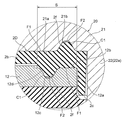
図4A及び図4Bは、外部端子20、ガスケット2、絶縁板3及び集電板30が、電池蓋12にかしめ固定される前後の状態を示す、電池蓋12の長手方向に沿う拡大断面図である。図5A及び図5Bは、それぞれ、図4A及び図4Bに対応するガスケット2の封止部Sの拡大断面図である。
4A and 4B are enlarged cross-sectional views along the longitudinal direction of the
前述のように、外部端子20、ガスケット2、絶縁板3及び集電板30は、例えば、以下の手順で電池蓋12にかしめ固定することができる。まず、図4Aに示すように、外部端子20の接続部22を、ガスケット2の貫通孔2a、電池蓋12の貫通孔12a、絶縁板3の貫通孔3a、及び集電板30の基部31の貫通孔31aに挿通させる。
As described above, the
ここで、ガスケット2は、外部端子20の溶接接合部21と電池蓋12との上面との間に配置される底部2bと、貫通孔12aの下方に延びて外部端子20の接続部22の外周面と電池蓋12の貫通孔12aの内周面との間に配置される筒状部2cとを有している。また、ガスケット2は、底部2bの周囲に、外部端子20の溶接接合部21の上端の一部を除いて溶接接合部21の側面を覆う側壁部2dを有している。これにより、外部端子20と電池蓋12との間にガスケット2が配置され、外部端子20と電池蓋12とがガスケット2によって電気的に絶縁される。
Here, the
次に、外部端子20の接続部22の先端の円筒状の部分を塑性変形させて拡径し、図4Bに示すように、集電板30の基部31の下面、すなわち電池容器10の内方側の面に接するかしめ部22cを形成する。これにより、集電板30の基部31は、絶縁板3によって電池蓋12に対して電気的に絶縁された状態で、外部端子20の接続部22に電気的に接続される。
Next, the cylindrical portion at the tip of the
また、外部端子20の接続部22は、基端側に径の大きい拡径部22aを有し、先端側に径の小さい縮径部22bを有し、拡径部22aと縮径部22bとの間に段差が形成されている。そのため、集電板30の基部31は、外部端子20の接続部22の段差とかしめ部22cとの間で保持される。これにより、ガスケット2は、底部2bが外部端子20の溶接接合部21と電池蓋12との間で所定の寸法に圧縮され、電池蓋12の貫通孔12aを封止する。
The connecting
ここで、ガスケット2は、底部2bの少なくとも一部が、電池蓋12の貫通孔12aからの電解液やガスの漏れを防止する封止部Sとされている。また、外部端子20と電池蓋12は、ガスケット2の封止部Sに密着する密着部21a,12bを有している。本実施形態において、外部端子20は、ガスケット2の底部2bに対向する溶接接合部21の下面の少なくとも一部に密着部21aを有している。また、電池蓋12は、ガスケット2の底部2bに対向する上面の一部に密着部12bを有している。外部端子20の密着部21a及び電池蓋12の密着部12bは、それぞれ、電池蓋12の外側で、電池蓋12の貫通孔12aの径方向外側に、貫通孔12aを囲む環状に設けられている。
Here, at least a part of the
ガスケット2は、圧縮前の状態において、封止部Sの外部端子20側に、突起状の圧縮部2fを有している。圧縮部2fは、図5A及び図5Bに示すように、外部端子20の密着部21aに向けて突出した状態から、その密着部21aによって圧縮される部分である。また、本実施形態のガスケット2は、圧縮前の状態で、圧縮された圧縮部2fを受容する凹部2eが、封止部Sの外部端子20側に圧縮部2fに隣接して設けられている。
The
図5Aに示すように、ガスケット2の圧縮前の状態で、圧縮部2fは、封止部Sの他の部分よりも、外部端子20の密着部21aに向けて突出している。すなわち、外部端子20の密着部21aに対向する圧縮部2fの端面F2は、圧縮部2f及び凹部2eが形成されていない封止部Sの基準面F1や、凹部2eの底面F3よりも、外部端子20の密着部21aに向けて突出している。
As shown in FIG. 5A, in a state before the
図5Bに示すように、ガスケット2の圧縮後の状態で、圧縮部2fは、外部端子20と電池蓋12の間で圧縮されて弾性変形し、外部端子20の密着部21aに沿う方向の寸法が拡大し、圧縮部2fの端面F2が外部端子20の密着部21aに所定の面圧で密着している。また、凹部2eは、弾性変形した圧縮部2fを受容することで小さくなるか又は消滅する。また、ガスケット2が密着部21aで圧縮されて弾性変形することで、ガスケット2の封止部Sの基準面F1は、外部端子20の密着部21aに所定の面圧で密着している。なお、ガスケット2は、圧縮によって一部が塑性流動して部分的に塑性変形してもよい。
As shown in FIG. 5B, in the state after compression of the
ここで、ガスケット2は、外部端子20と電池蓋12との間で圧縮された状態で、圧縮部2fの弾性変形量が、封止部Sの他の部分の弾性変形量よりも多くなる。そのため、ガスケット2は、外部端子20と電池蓋12との間で圧縮された状態で、圧縮部2fの端面F2と外部端子20の密着部21aとの接触面圧が、封止部Sの他の部分、すなわち基準面F1と外部端子20の密着部21aとの接触面圧よりも高くなる。
Here, when the
また、ガスケット2は、外部端子20と電池蓋12との間で圧縮された状態で、凹部2eが変形した圧縮部2fを受容することで消滅し、凹部2eの底面であった面F3の一部又は全部と外部端子20の密着部21aとが密着することが考えられる。この場合、凹部2eの底面であった面F3と外部端子20の密着部21aとの接触面圧は、封止部Sの基準面F1と外部端子20の密着部21aとの接触面圧よりも低くなる。また、ガスケット2の電池蓋12に対向する封止部Sの基準面F1と、電池蓋12の密着部12bとの接触面圧は、ガスケット2の反対側の面F1,F2,F3の接触面圧に応じて変化し、反対側に圧縮部2fを有する部分で最大となる。
Further, the
また、本実施形態において、ガスケット2の圧縮部2fは、封止部Sの表面、すなわち基準面F1に対して垂直に突出する矩形の断面形状を有し、先端の角部C1が丸みを帯びている。また、ガスケット2の凹部2eは、封止部Sの表面、すなわち基準面F1に対して傾斜する傾斜面2gを有している。
In the present embodiment, the
以下、本実施形態の二次電池100の作用について説明する。
Hereinafter, the operation of the
本実施形態の二次電池100は、前述のように、正負の電極41,42を捲回した電極群40と、電極群40及び電解液を収容する電池缶11と、電池缶11の開口部11dを封止する電池蓋12と、電池蓋12の貫通孔12aを貫通して正負の集電板30A,30Bを介して正負の電極41,42に電気的に接続される正負の外部端子20A,20Bとを備えている。また、二次電池100は、外部端子20と電池蓋12との間で圧縮されて電池蓋12の貫通孔12aを封止するガスケット2を備えている。
As described above, the
このような構成を有する二次電池100は、例えば、外部端子20の溶接接合部21の上面にバスバーが溶接され、複数の二次電池100を直列に接続した組電池として用いられる。二次電池100は、例えば、発電機等の電力供給源から供給された電力を、外部端子20及び集電板30を介して電極群40に蓄積することで充電される。また、二次電池100は、電極群40に蓄積した電力を、集電板30及び外部端子20を介して、例えば、モーター等の電力を消費する装置に供給する。
The
ここで、外部端子20と電池蓋12は、図5A及び図5Bに示すように、ガスケット2の封止部Sの表裏に密着する密着部21a,12bを有している。これにより、ガスケット2の封止部Sが、外部端子20の密着部21aと電池蓋12の密着部12bに密着し、電池蓋12の外側で貫通孔12aの周囲を液密かつ気密に封止して、電池容器10内の電解液やガスが外部に漏洩するのを防止できる。
Here, as shown in FIGS. 5A and 5B, the
さらに、本実施形態のガスケット2は、封止部Sの外部端子20側に、外部端子20の密着部21aに向けて突出した状態から、その密着部21aによって圧縮される圧縮部2fを有している。これにより、圧縮部2fにおけるガスケット2の弾性変形量を増加させ、圧縮部2fの端面F2を外部端子20の密着部21aに対してより強い面圧で密着させることができる。したがって、圧縮部2fを有しない場合と比較して、ガスケット2の密閉性を向上させることができる。
Furthermore, the
加えて、本実施形態のガスケット2には、圧縮された圧縮部2fを受容する凹部2eが設けられている。これにより、ガスケット2の圧縮部2fの端面F2が封止部Sの基準面F1と同じ高さになるまで圧縮部2fを圧縮しつつ、変形後の圧縮部2fを凹部2e内の空間に受容し、基準面F1を外部端子20の密着部21aに密着させることができる。したがって、圧縮後のガスケット2の寸法を均一にすることができ、ガスケット2の密閉性が低下するのを防止できる。また、ガスケット2に凹部2eを設けることで、外部端子20及び電池蓋12に特別な加工をする必要がなく、製造工程を容易にして生産性の低下を防止できる。
In addition, the
これに対し、ガスケット2が、圧縮された圧縮部2fを受容する凹部2eを有しない場合には、変形後の圧縮部2fを受容する空間がないため、ガスケット2の圧縮部2fの端面F2と封止部Sの基準面F1とを同じ高さにするのが困難であり、圧縮後のガスケット2の寸法が安定しない。この場合、ガスケット2の封止部Sの基準面F1と、外部端子20の密着部21aとの間に隙間が生じ、ガスケット2の密閉性が低下することになる。
On the other hand, when the
また、本実施形態のガスケット2は、外部端子20と電池蓋12との間で圧縮された状態で、圧縮部2fの端面F2と外部端子20の密着部21aとの接触面圧が、封止部Sの基準面F1と外部端子20の密着部21aとの接触面圧よりも高い。これにより、ガスケット2は、圧縮部2fが形成された部分において、より高い密閉性を得ることができる。
Further, in the
また、ガスケット2の圧縮部2fは、封止部Sの表面、すなわち基準面F1に対して垂直に突出する矩形の断面形状を有している。これにより、圧縮部2fの端面F2の面積を確保するとともに、圧縮部2fを圧縮しやすくすることができる。また、ガスケット2の凹部2eは、封止部Sの表面、すなわち基準面F1に対して傾斜する傾斜面2gを有している。これにより、凹部2e内の傾斜面2gを外部端子20の密着部21aに密着させ、封止部Sのリークパスを長くすることができる。
Moreover, the
以上説明したように、本実施形態の二次電池100によれば、ガスケット2による電池蓋12の貫通孔12aの密閉性を向上させ、かつ、圧縮後のガスケット2の寸法を均一にすることができる。
As described above, according to the
なお、本実施形態では、ガスケット2が、封止部Sの外部端子20側に、外部端子20の密着部21aに向けて突出した状態からその密着部21aによって圧縮される圧縮部2fと、圧縮された圧縮部2fを受容する凹部2eを有する場合について説明した。しかし、二次電池100は、ガスケット2が、外部端子20側の圧縮部2f及び凹部2eに替えて、又は、外部端子20側の圧縮部2f及び凹部2eとともに、以下の構成を有してもよい。すなわち、ガスケット2は、封止部Sの電池蓋12側に、電池蓋12の密着部12bに向けて突出した状態からその密着部12bによって圧縮される圧縮部と、圧縮された圧縮部を受容する凹部とを有してもよい。この場合にも、本実施形態の二次電池100と同様の効果を得ることができる。
In the present embodiment, the
(実施形態2)
以下、本発明の二次電池の実施形態2について、図1から図4Bまでを援用し、図6A及び図6Bを用いて説明する。図6A及び図6Bは、前述の実施形態1で説明した図5A及び図5Bに対応する本実施形態の二次電池の拡大断面図である。
(Embodiment 2)
Hereinafter,
本実施形態の二次電池は、ガスケット2Aが凹部2eを有しておらず、外部端子20の密着部21aに、圧縮された圧縮部2fを受容する凹部21bが設けられている点で、前述の実施形態1で説明した二次電池100と異なっている。本実施形態の二次電池のその他の点は、前述の実施形態1で説明した二次電池100と同一であるので、同一の部分は、同一の符号を付して説明を省略する。
In the secondary battery of the present embodiment, the
ガスケット2Aの圧縮部2fは、電池蓋12の貫通孔12aを囲むように環状に設けられ、矩形状の断面形状を有している。外部端子20の密着部21aに設けられた凹部21bは、電池蓋12の貫通孔12aを囲むように環状に設けられ、底部の幅よりも開口部の幅が広い台形状の断面形状を有し、封止部Sの表面、すなわち基準面F1に対して傾斜する傾斜面21cを有している。
The
圧縮部2fの幅は、凹部21bの底部の幅よりも広く、凹部21bの開口部の幅よりも狭い。そのため、圧縮部2fは、図6Aに示すガスケット2Aの圧縮前の状態で、矩形状の断面形状の丸みを帯びた角部C1が、外部端子20の密着部21aに設けられた凹部21bの傾斜面21cに当接している。また、圧縮部2fは、図6Bに示すガスケット2Aの圧縮後の状態で、先端部が幅方向及び高さ方向に圧縮されて凹部21bに受容され、凹部21bの傾斜面21cに密着している。ガスケット2の圧縮後の寸法を安定させるために、圧縮部2fの端面F2と凹部21bの底面との間には、僅かに隙間が形成されていることが好ましい。
The width of the
また、本実施形態のガスケット2Aは、外部端子20と電池蓋12との間で圧縮された状態で、圧縮部2fの角部C1と外部端子20の密着部21aに設けられた凹部21bの傾斜面21cとの接触面圧が、封止部Sの他の部分すなわち基準面F1と外部端子20の密着部21aとの接触面圧よりも高い。
In addition, the
以下、本実施形態の二次電池の作用について説明する。 Hereinafter, the operation of the secondary battery of the present embodiment will be described.
本実施形態の二次電池が備えるガスケット2Aは、封止部Sの外部端子20側に、その封止部Sに対向する外部端子20の密着部21aに向けて突出した状態からその密着部21aによって圧縮される圧縮部2fを有している。また、本実施形態の外部端子20は、溶接接合部21の密着部21aに、圧縮された圧縮部2fを受容する凹部21bが設けられている。
The
これにより、圧縮部2fの角部C1を封止部Sの他の部分よりも圧縮しつつ、ガスケット2Aの封止部Sの表裏の基準面F1を、それぞれ外部端子20の密着部21aと電池蓋12の密着部12bに密着させることができる。また、ガスケット2Aが凹部を有しないので、ガスケット2Aの封止部Sの基準面F1と外部端子20の密着部21aとの接触面積を増加させ、リークパスを長くすることができる。したがって、実施形態1の二次電池100と同様に、電池蓋12の外側で貫通孔12aの周囲を液密かつ気密に封止して、電池缶11内の電解液やガスが外部に漏洩するのを防止できる。
As a result, while compressing the corner C1 of the
また、圧縮されて変形した圧縮部2fが外部端子20の密着部21aに設けられた凹部21bに受容されることで、圧縮部2fの端面F2と封止部Sの基準面F1とが同じ高さになるまで圧縮部2fを圧縮することなく、基準面F1を外部端子20の密着部21aに密着させることができる。したがって、圧縮後のガスケット2Aの寸法を均一にすることができ、ガスケット2Aの密閉性が低下するのを防止できる。
Further, the
また、圧縮部2fの角部C1と外部端子20の密着部21aに設けられた凹部21bの傾斜面21cとの接触面圧が、封止部Sの他の部分と外部端子20の密着部21aとの接触面圧よりも高い。これにより、ガスケット2Aは、圧縮部2fが形成された部分において、より高い密閉性を得ることができる。また、外部端子20の凹部21bは、ガスケット2Aの封止部Sの表面、すなわち基準面F1に対して傾斜する傾斜面21cを有している。これにより、外部端子20の密着部21aに鍛造によって凹部21bを容易に形成することができる。
Further, the contact surface pressure between the corner portion C1 of the
以上説明したように、本実施形態の二次電池によれば、ガスケット2Aによる電池蓋12の貫通孔12aの密閉性を向上させ、かつ、圧縮後のガスケット2Aの寸法を均一にすることができる。
As described above, according to the secondary battery of the present embodiment, the sealing performance of the through
(実施形態3)
以下、本発明の二次電池の実施形態3について、図1から図4Bまでを援用し、図7A及び図7Bを用いて説明する。図7A及び図7Bは、前述の実施形態1で説明した図5A及び図5Bに対応する本実施形態の二次電池の拡大断面図である。
(Embodiment 3)
Hereinafter,
本実施形態の二次電池は、ガスケット2Bが凹部2eを有しておらず、電池蓋12の密着部12bに、圧縮された圧縮部2fを受容する凹部12cが設けられている点で、前述の実施形態1で説明した二次電池100と異なっている。本実施形態の二次電池のその他の点は、前述の実施形態1で説明した二次電池100と同一であるので、同一の部分は、同一の符号を付して説明を省略する。
In the secondary battery of the present embodiment, the
ガスケット2Bの圧縮部2fは、電池蓋12の貫通孔12aを囲むように環状に設けられ、矩形状の断面形状を有している。電池蓋12の密着部12bに設けられた凹部12cは、電池蓋12の貫通孔12aを囲むように環状に設けられ、底部の幅よりも開口部の幅が広い台形状の断面形状を有し、封止部Sの表面、すなわち基準面F1に対して傾斜する傾斜面12dを有している。
The
圧縮部2fの幅は、凹部12cの底部の幅よりも広く、凹部12cの開口部の幅よりも狭い。そのため、圧縮部2fは、図7Aに示すガスケット2Bの圧縮前の状態で、矩形状の断面形状の丸みを帯びた角部C1が、電池蓋12の密着部12bに設けられた凹部12cの傾斜面12dに当接している。また、圧縮部2fは、図7Bに示すガスケット2Bの圧縮後の状態で、先端部が幅方向及び高さ方向に圧縮されて凹部12cに受容され、凹部12cの傾斜面12dに密着している。ガスケット2の圧縮後の寸法を安定させるために、圧縮部2fの端面F2と凹部12cの底面との間には、僅かに隙間が形成されていることが好ましい。
The width of the
また、本実施形態のガスケット2Bは、外部端子20と電池蓋12との間で圧縮された状態で、圧縮部2fの角部C1と電池蓋12の密着部12bに設けられた凹部12cの傾斜面12dとの接触面圧が、封止部Sの他の部分と電池蓋12の密着部12bとの接触面圧よりも高い。
In addition, the
以下、本実施形態の二次電池の作用について説明する。 Hereinafter, the operation of the secondary battery of the present embodiment will be described.
本実施形態のガスケット2Bは、封止部Sの電池蓋12側に、電池蓋12の密着部12bに向けて突出した状態からその密着部12bによって圧縮される圧縮部2fを有している。また、本実施形態の電池蓋12は、密着部12bに、圧縮された圧縮部2fを受容する凹部12cが設けられている。
The
これにより、圧縮部2fの角部C1を封止部Sの他の部分よりも圧縮しつつ、ガスケット2Bの封止部Sの表裏の基準面F1を、それぞれ外部端子20の密着部21aと電池蓋12の密着部12bに密着させることができる。また、ガスケット2Bが凹部を有しないので、ガスケット2Bの封止部Sの基準面F1と外部端子20の密着部21aとの接触面積を増加させ、リークパスを長くすることができる。したがって、実施形態1の二次電池100と同様に、電池蓋12の外側で貫通孔12aの周囲を液密かつ気密に封止して、電池缶11内の電解液やガスが外部に漏洩するのを防止できる。
As a result, while compressing the corner C1 of the
また、圧縮されて変形する圧縮部2fを電池蓋12の密着部12bに設けられた凹部12cに受容することで、圧縮部2fの端面F2と封止部Sの基準面F1とが同じ高さになるまで圧縮部2fを圧縮することなく、基準面F1を電池蓋12の密着部12bに密着させることができる。したがって、圧縮後のガスケット2Bの寸法を均一にすることができ、ガスケット2Bの密閉性が低下するのを防止できる。
Further, by receiving the
また、圧縮部2fの角部C1と電池蓋12の密着部12bに設けられた凹部12cの傾斜面12dとの接触面圧が、封止部Sの他の部分と電池蓋12の密着部12bとの接触面圧よりも高い。これにより、ガスケット2Bは、圧縮部2fが形成された部分において、より高い密閉性を得ることができる。また、電池蓋12の凹部12cは、ガスケット2Bの封止部Sの表面、すなわち基準面F1に対して傾斜する傾斜面12dを有している。これにより、電池蓋12の密着部12bに鍛造によって凹部12cを容易に形成することができる。また、電池蓋12にガス排出弁13を形成する鍛造工程と同時に凹部12cを形成することで、生産性が低下するのを防止できる。
Further, the contact surface pressure between the corner portion C1 of the
以上説明したように、本実施形態の二次電池によれば、ガスケット2Bによる電池蓋12の貫通孔12aの密閉性を向上させ、かつ、圧縮後のガスケット2Bの寸法を均一にすることができる。
As described above, according to the secondary battery of the present embodiment, the sealing performance of the through
(実施形態4)
以下、本発明の二次電池の実施形態4について、図1から図4Bまでを援用し、図8A及び図8Bを用いて説明する。図8A及び図8Bは、前述の実施形態1で説明した図5A及び図5Bに対応する本実施形態の二次電池の拡大断面図である。
(Embodiment 4)
Hereinafter, Embodiment 4 of the secondary battery of the present invention will be described with reference to FIGS. 8A and 8B with reference to FIGS. 1 to 4B. 8A and 8B are enlarged cross-sectional views of the secondary battery according to the present embodiment corresponding to FIGS. 5A and 5B described in the first embodiment.
本実施形態の二次電池は、ガスケット2Cが封止部Sに複数の圧縮部2fを有し、圧縮部2fの間に凹部2eが設けられている点で、前述の実施形態1で説明した二次電池100と異なっている。本実施形態の二次電池のその他の点は、前述の実施形態1で説明した二次電池100と同一であるので、同一の部分は、同一の符号を付して説明を省略する。
The secondary battery of the present embodiment has been described in the above-described first embodiment in that the
本実施形態の二次電池によれば、前述の実施形態1の二次電池と同様の効果が得られるだけでなく、ガスケット2Cが複数の圧縮部2fを有することで、より高い密閉性を得ることができる。なお、ガスケット2Cが有する圧縮部2fの数は、2つに限定されず、3つ以上であってもよい。
According to the secondary battery of the present embodiment, not only the same effect as the secondary battery of the first embodiment described above is obtained, but also the
(実施形態5)
以下、本発明の二次電池の実施形態5について、図1から図4Bまでを援用し、図9A及び図9Bを用いて説明する。図9A及び図9Bは、前述の実施形態1で説明した図5A及び図5Bに対応する本実施形態の二次電池の拡大断面図である。
(Embodiment 5)
Hereinafter, Embodiment 5 of the secondary battery of the present invention will be described with reference to FIGS. 9A and 9B with reference to FIGS. 9A and 9B are enlarged cross-sectional views of the secondary battery of the present embodiment corresponding to FIGS. 5A and 5B described in the first embodiment.
本実施形態の二次電池は、ガスケット2Dが、封止部Sの外部端子20側と電池蓋12側の圧縮方向に重ならない位置にそれぞれ圧縮部2fを有し、外部端子20の密着部21aと電池蓋12の密着部12bにそれぞれ凹部21b,12cが設けられている点で、前述の実施形態1で説明した二次電池100と異なっている。本実施形態の二次電池のその他の点は、前述の実施形態1で説明した二次電池100と同一であるので、同一の部分は、同一の符号を付して説明を省略する。
The secondary battery of this embodiment has the
本実施形態の二次電池によれば、前述の実施形態2及び3の二次電池と同様の効果が得られるだけでなく、ガスケット2Dが、封止部Sの表裏の双方に圧縮部2fを有することで、より高い密閉性を得ることができる。なお、ガスケット2Dが有する圧縮部2fの数とそれに対応する凹部21b,12cの数は、3つ以上であってもよい。
According to the secondary battery of the present embodiment, not only the same effects as those of the secondary batteries of the above-described
以上、図面を用いて本発明の実施の形態を詳述してきたが、具体的な構成はこの実施形態に限定されるものではなく、本発明の要旨を逸脱しない範囲における設計変更等があっても、それらは本発明に含まれるものである。 The embodiment of the present invention has been described in detail with reference to the drawings, but the specific configuration is not limited to this embodiment, and there are design changes and the like without departing from the gist of the present invention. They are also included in the present invention.
2,2A−2D ガスケット、2e 凹部、2f 圧縮部、2g 傾斜面、11 電池缶、11d 開口部、12 電池蓋、12a 貫通孔、12b 密着部、12c 凹部、12d 傾斜面、20 外部端子、20A 正極外部端子、20B 負極外部端子、21a 密着部、21b 凹部、21c 傾斜面、100 二次電池、F1 基準面(封止部の表面)、S 封止部 2, 2A-2D gasket, 2e recess, 2f compression part, 2g inclined surface, 11 battery can, 11d opening, 12 battery lid, 12a through hole, 12b contact part, 12c recess, 12d inclined surface, 20 external terminal, 20A Positive external terminal, 20B Negative external terminal, 21a adhesion part, 21b recessed part, 21c inclined surface, 100 secondary battery, F1 reference surface (surface of sealing part), S sealing part
Claims (7)
前記外部端子と前記電池蓋は、それぞれ前記ガスケットの封止部に密着する密着部を有し、
前記ガスケットは、少なくとも一方の前記密着部に向けて突出した状態から該密着部によって圧縮される圧縮部を有し、
前記密着部に、圧縮された前記圧縮部を受容する凹部が設けられ、
前記凹部は、前記封止部の表面に対して傾斜する傾斜面を有し、
前記圧縮部は、前記封止部の表面に対して垂直に突出する矩形の断面形状を有し、前記ガスケットの圧縮前の状態で前記矩形の断面形状の角部が前記凹部の前記傾斜面に当接し、前記ガスケットの圧縮後の状態で先端部が幅方向および高さ方向に圧縮されて前記凹部に受容され前記傾斜面に密着していることを特徴とする二次電池。 A battery can that contains the electrolyte; a battery lid that seals the opening of the battery can; an external terminal that penetrates the through hole of the battery lid; and the external terminal that is disposed around the through hole and A secondary battery comprising a gasket that is compressed between the battery lid and seals the through hole,
The external terminal and the battery lid each have a close contact portion that is in close contact with the sealing portion of the gasket,
The gasket has a compression portion that is compressed by the close contact portion from a state protruding toward at least one of the close contact portions,
Before SL close contact portion, the recess for receiving is provided a compressed the compression unit,
The concave portion has an inclined surface inclined with respect to the surface of the sealing portion,
The compression portion has a rectangular cross-sectional shape that protrudes perpendicularly to the surface of the sealing portion, and a corner portion of the rectangular cross-sectional shape is in the inclined surface of the recess in a state before compression of the gasket. The secondary battery is in contact with each other , and in a state after compression of the gasket, a tip portion is compressed in the width direction and the height direction, is received in the concave portion, and is in close contact with the inclined surface .
前記凹部は、前記外部端子の前記密着部に設けられていることを特徴とする請求項2に記載の二次電池。 The gasket has a compression portion that is compressed by the contact portion from a state protruding toward the contact portion of the external terminal,
The secondary battery according to claim 2, wherein the recess is provided in the contact portion of the external terminal.
前記凹部は、前記電池蓋の前記密着部に設けられていることを特徴とする請求項2から請求項4のいずれか一項に記載の二次電池。 The gasket has a compression portion that is compressed by the contact portion from a state protruding toward the contact portion of the battery lid,
The secondary battery according to any one of claims 2 to 4 , wherein the recess is provided in the contact portion of the battery lid.
Priority Applications (1)
| Application Number | Priority Date | Filing Date | Title |
|---|---|---|---|
| JP2014223282A JP6446239B2 (en) | 2014-10-31 | 2014-10-31 | Secondary battery |
Applications Claiming Priority (1)
| Application Number | Priority Date | Filing Date | Title |
|---|---|---|---|
| JP2014223282A JP6446239B2 (en) | 2014-10-31 | 2014-10-31 | Secondary battery |
Publications (2)
| Publication Number | Publication Date |
|---|---|
| JP2016091720A JP2016091720A (en) | 2016-05-23 |
| JP6446239B2 true JP6446239B2 (en) | 2018-12-26 |
Family
ID=56019523
Family Applications (1)
| Application Number | Title | Priority Date | Filing Date |
|---|---|---|---|
| JP2014223282A Active JP6446239B2 (en) | 2014-10-31 | 2014-10-31 | Secondary battery |
Country Status (1)
| Country | Link |
|---|---|
| JP (1) | JP6446239B2 (en) |
Families Citing this family (8)
| Publication number | Priority date | Publication date | Assignee | Title |
|---|---|---|---|---|
| JP6616952B2 (en) * | 2015-03-25 | 2019-12-04 | Fdk株式会社 | Cylindrical battery sealing body and cylindrical battery |
| WO2016170920A1 (en) * | 2015-04-21 | 2016-10-27 | 日立オートモティブシステムズ株式会社 | Rectangular secondary battery |
| US10833299B2 (en) | 2015-12-28 | 2020-11-10 | Gs Yuasa International Ltd. | Sealing member, energy storage device and method of manufacturing energy storage device |
| JP6731176B2 (en) | 2016-01-21 | 2020-07-29 | 株式会社Gsユアサ | Electric storage element and method for manufacturing electric storage element |
| JP2018098130A (en) * | 2016-12-16 | 2018-06-21 | 株式会社Gsユアサ | Power storage element |
| JP2019029225A (en) | 2017-07-31 | 2019-02-21 | リチウム エナジー アンド パワー ゲゼルシャフト ミット ベシュレンクテル ハフッング ウント コンパニー コマンディトゲゼルシャフトLithium Energy and Power GmbH & Co. KG | Power storage element |
| WO2019151359A1 (en) * | 2018-01-31 | 2019-08-08 | 株式会社Gsユアサ | Power storage element |
| JP7069941B2 (en) * | 2018-03-28 | 2022-05-18 | 株式会社Gsユアサ | Power storage element |
Family Cites Families (4)
| Publication number | Priority date | Publication date | Assignee | Title |
|---|---|---|---|---|
| JP5021900B2 (en) * | 2005-02-04 | 2012-09-12 | Necエナジーデバイス株式会社 | Sealed battery |
| JP2010277742A (en) * | 2009-05-27 | 2010-12-09 | Toyota Motor Corp | Battery cell, and fuel battery |
| JP5482991B2 (en) * | 2009-07-14 | 2014-05-07 | Nok株式会社 | Fuel cell sealing structure |
| KR101116492B1 (en) * | 2010-02-12 | 2012-02-27 | 에스비리모티브 주식회사 | Rechargeable battery |
-
2014
- 2014-10-31 JP JP2014223282A patent/JP6446239B2/en active Active
Also Published As
| Publication number | Publication date |
|---|---|
| JP2016091720A (en) | 2016-05-23 |
Similar Documents
| Publication | Publication Date | Title |
|---|---|---|
| JP6446239B2 (en) | Secondary battery | |
| JP5452303B2 (en) | Secondary battery and manufacturing method thereof | |
| JP6328271B2 (en) | Prismatic secondary battery | |
| JP6363893B2 (en) | Secondary battery | |
| JP6198844B2 (en) | Assembled battery | |
| US20120301757A1 (en) | Rectangular battery | |
| JP6892495B2 (en) | Secondary battery | |
| JP5087110B2 (en) | Secondary battery | |
| JPWO2015141570A1 (en) | Secondary battery | |
| JP6577998B2 (en) | Prismatic secondary battery | |
| JP6530819B2 (en) | Secondary battery | |
| JP6403644B2 (en) | Secondary battery | |
| WO2016088505A1 (en) | Rectangular secondary cell | |
| JP6562726B2 (en) | Rectangular secondary battery and manufacturing method thereof | |
| WO2017130702A1 (en) | Rectangular secondary battery | |
| JP6382336B2 (en) | Prismatic secondary battery | |
| JP2015103420A (en) | Square secondary battery | |
| JP2015065048A (en) | Square secondary battery and battery pack | |
| JP6235422B2 (en) | Secondary battery | |
| WO2015125223A1 (en) | Secondary battery | |
| JP2016173907A (en) | Square secondary battery | |
| JP2015204236A (en) | Secondary battery and battery module | |
| JP6892338B2 (en) | Power storage device and manufacturing method of power storage device | |
| JP2018056086A (en) | Secondary battery and method of manufacturing secondary battery | |
| JP7065965B2 (en) | Secondary battery |
Legal Events
| Date | Code | Title | Description |
|---|---|---|---|
| A621 | Written request for application examination |
Free format text: JAPANESE INTERMEDIATE CODE: A621 Effective date: 20170713 |
|
| A977 | Report on retrieval |
Free format text: JAPANESE INTERMEDIATE CODE: A971007 Effective date: 20180711 |
|
| A131 | Notification of reasons for refusal |
Free format text: JAPANESE INTERMEDIATE CODE: A131 Effective date: 20180724 |
|
| A521 | Request for written amendment filed |
Free format text: JAPANESE INTERMEDIATE CODE: A523 Effective date: 20180913 |
|
| TRDD | Decision of grant or rejection written | ||
| A01 | Written decision to grant a patent or to grant a registration (utility model) |
Free format text: JAPANESE INTERMEDIATE CODE: A01 Effective date: 20181106 |
|
| A61 | First payment of annual fees (during grant procedure) |
Free format text: JAPANESE INTERMEDIATE CODE: A61 Effective date: 20181203 |
|
| R150 | Certificate of patent or registration of utility model |
Ref document number: 6446239 Country of ref document: JP Free format text: JAPANESE INTERMEDIATE CODE: R150 |
|
| S111 | Request for change of ownership or part of ownership |
Free format text: JAPANESE INTERMEDIATE CODE: R313111 |
|
| R350 | Written notification of registration of transfer |
Free format text: JAPANESE INTERMEDIATE CODE: R350 |
|
| R250 | Receipt of annual fees |
Free format text: JAPANESE INTERMEDIATE CODE: R250 |
|
| R250 | Receipt of annual fees |
Free format text: JAPANESE INTERMEDIATE CODE: R250 |
|
| R250 | Receipt of annual fees |
Free format text: JAPANESE INTERMEDIATE CODE: R250 |