JP6439963B2 - Holding tool and manufacturing method thereof - Google Patents
Holding tool and manufacturing method thereof Download PDFInfo
- Publication number
- JP6439963B2 JP6439963B2 JP2014169286A JP2014169286A JP6439963B2 JP 6439963 B2 JP6439963 B2 JP 6439963B2 JP 2014169286 A JP2014169286 A JP 2014169286A JP 2014169286 A JP2014169286 A JP 2014169286A JP 6439963 B2 JP6439963 B2 JP 6439963B2
- Authority
- JP
- Japan
- Prior art keywords
- holding
- polishing
- holding pad
- pad
- frame member
- Prior art date
- Legal status (The legal status is an assumption and is not a legal conclusion. Google has not performed a legal analysis and makes no representation as to the accuracy of the status listed.)
- Active
Links
Images


Classifications
-
- B—PERFORMING OPERATIONS; TRANSPORTING
- B24—GRINDING; POLISHING
- B24B—MACHINES, DEVICES, OR PROCESSES FOR GRINDING OR POLISHING; DRESSING OR CONDITIONING OF ABRADING SURFACES; FEEDING OF GRINDING, POLISHING, OR LAPPING AGENTS
- B24B37/00—Lapping machines or devices; Accessories
- B24B37/27—Work carriers
- B24B37/30—Work carriers for single side lapping of plane surfaces
-
- H—ELECTRICITY
- H01—ELECTRIC ELEMENTS
- H01L—SEMICONDUCTOR DEVICES NOT COVERED BY CLASS H10
- H01L21/00—Processes or apparatus adapted for the manufacture or treatment of semiconductor or solid state devices or of parts thereof
- H01L21/02—Manufacture or treatment of semiconductor devices or of parts thereof
- H01L21/04—Manufacture or treatment of semiconductor devices or of parts thereof the devices having at least one potential-jump barrier or surface barrier, e.g. PN junction, depletion layer or carrier concentration layer
- H01L21/18—Manufacture or treatment of semiconductor devices or of parts thereof the devices having at least one potential-jump barrier or surface barrier, e.g. PN junction, depletion layer or carrier concentration layer the devices having semiconductor bodies comprising elements of Group IV of the Periodic System or AIIIBV compounds with or without impurities, e.g. doping materials
- H01L21/30—Treatment of semiconductor bodies using processes or apparatus not provided for in groups H01L21/20 - H01L21/26
- H01L21/302—Treatment of semiconductor bodies using processes or apparatus not provided for in groups H01L21/20 - H01L21/26 to change their surface-physical characteristics or shape, e.g. etching, polishing, cutting
- H01L21/304—Mechanical treatment, e.g. grinding, polishing, cutting
Description
本発明は、保持具及びその製造方法に関し、特に、研磨パッドを用いて被研磨物を研磨する際に、被研磨物を保持するための保持具及びその製造方法に関する。 The present invention relates to a holder and a method for manufacturing the same, and more particularly to a holder for holding an object to be polished and a method for manufacturing the same when polishing the object to be polished using a polishing pad.
従来、フラットパネルディスプレイ(FPD)用ガラス基板、カラーフィルタ、シリコンウェハ、インジウム錫酸化物(ITO)成膜済基板等の材料(被研磨物)では、高精度な平坦性が要求されるため、研磨布を使用した研磨加工が行われている。通常、これらの被研磨物の研磨加工には、被研磨物を片面研磨加工する片面研磨機が使用されている。この片面研磨機では、保持用定盤に被研磨物が保持され、研磨用定盤に研磨布が装着されている。研磨加工時には、研磨粒子を含む研磨液を供給し、被研磨物に圧力をかけながら両定盤を回転させることで被研磨物が研磨加工される。 Conventionally, materials such as glass substrates for flat panel displays (FPD), color filters, silicon wafers, indium tin oxide (ITO) deposited substrates, etc., require high-precision flatness. Polishing using an abrasive cloth is performed. Usually, a single-side polishing machine that performs single-side polishing of an object to be polished is used for polishing the object to be polished. In this single-side polishing machine, an object to be polished is held on a holding surface plate, and a polishing cloth is attached to the polishing surface plate. At the time of polishing, the polishing object is polished by supplying a polishing liquid containing abrasive particles and rotating both surface plates while applying pressure to the object to be polished.
一般に、片面研磨機を使用した研磨加工では、被研磨物が金属製の保持用定盤と直接接触することで生じる被研磨物のスクラッチ等を抑制するため、保持用定盤に軟質クロス等の保持パッドを備える保持具が装着されている。保持パッドの装着によりスクラッチ等を回避することはできるが、保持パッドおよび被研磨物間の粘着性や静摩擦が不十分なとき、すなわち、保持パッドの被研磨物保持性が不十分なときは、研磨加工中に被研磨物の横ずれが生じるため、被研磨物を平坦に研磨加工することが難しくなる。この横ずれを抑制するため、保持パッドの周縁に沿って、被研磨物を挿入可能な開口が形成されたテンプレートを取り付けた保持具が知られている(例えば、特許文献1又は2)。
In general, in a polishing process using a single-side polishing machine, the holding surface plate is made of a soft cloth or the like in order to suppress scratches or the like of the object to be polished that occurs when the object is in direct contact with a metal holding surface plate. A holding tool having a holding pad is attached. Although it is possible to avoid scratches and the like by attaching the holding pad, when the adhesiveness and static friction between the holding pad and the object to be polished are insufficient, that is, when the object holding ability of the holding pad is insufficient, Since the lateral shift of the object to be polished occurs during the polishing process, it becomes difficult to polish the object to be polished flatly. In order to suppress this lateral displacement, a holder is known in which a template in which an opening into which an object can be inserted is formed is formed along the periphery of the holding pad (for example,
特許文献1では、被研磨物の周縁の過研磨による、いわゆる縁ダレを防止するため、及び被研磨物の脱落を防止するために、被研磨物を囲む枠材を設け、枠材内に被研磨物同程度サイズの保持パッドを配し、該保持パッドにより被研磨物を保持している。特許文献2では、保持パッド上に貼り付けた枠材の穴に沿う形で保持パッドの枠材内周に沿って切りこみを入れたテンプレートが開示されている。
In
特許文献1のような、いわゆるインサート式の保持具では、従来技術と異なり保持パッドが独立して形成されており、枠材が硬いキャリアプレートに直接固定されているため、枠材に水平・垂直方向のクッション性がない。このため、インサート式の保持具を用いた場合、研磨圧によって被研磨物が研磨パッド側に押し込まれると、それによって研磨パッドが枠材の周辺に強く押し当てられることとなる。そして、研磨パッドが枠材の周辺に強く押し当てられた状態で研磨パッド及びキャリアプレートを回転させると、研磨パッド或いは枠材表面を傷付けてしまう場合がある。
In the so-called insert-type holder as in
これを防止するために、特許文献2のように、枠材と定盤との間に枠材の内側にスリットを入れた保持パッドを設けることが考えられる。しかしながら、特許文献2の保持パッドでは、枠材を保持パッドのスキン層上に接着しているため、研磨時に枠材に水平方向の力が加わると、枠材が保持パッドから剥離し易い、という問題があった。また、特許文献2の保持パッドでは、保持パッドに切込みが形成されているため、研磨加工時の摺動に伴い枠材を支持する保持パッドの揺動が大きく、枠材を支持している保持パッドの一部に切り込みが形成されているため、切り込み部より使用時間が長くなると保持パッドへのダメージが蓄積されやすく保持パッドが破損して被研磨物が外れ、クラッシュしてしまう恐れがあった。 In order to prevent this, it is conceivable to provide a holding pad with a slit inside the frame material between the frame material and the surface plate as in Patent Document 2. However, in the holding pad of Patent Document 2, since the frame material is bonded onto the skin layer of the holding pad, when a horizontal force is applied to the frame material during polishing, the frame material is easily peeled off from the holding pad. There was a problem. In addition, in the holding pad of Patent Document 2, since the notch is formed in the holding pad, the holding pad that supports the frame material greatly swings with sliding during polishing, and the holding pad that supports the frame material is held. Since a notch is formed in a part of the pad, if the usage time is longer than the notched part, damage to the holding pad is likely to be accumulated, and the holding pad may be damaged and the object to be polished may come off and crash. .
そこで本発明は、上述した問題点を解決するためになされたものであり、発泡ポリウレタン製の保持パッドを用いた保持具であって、被研磨物の縁ダレ及び被研磨物の脱落を防止しつつ、研磨パッドが傷付くのを防止し、かつ枠材の剥離をも防止することができる、研磨装置用の保持具を提供することを目的とする。 Accordingly, the present invention has been made to solve the above-described problems, and is a holder using a polyurethane polyurethane holding pad, which prevents the sag of the object to be polished and the falling of the object to be polished. On the other hand, it is an object of the present invention to provide a holding tool for a polishing apparatus that can prevent the polishing pad from being damaged and also prevent the peeling of the frame material.
上述した課題を解決するために、本発明は、被研磨物の研磨時に被研磨物を保持する保持具であって、内部に多数の気泡を有する発泡ポリウレタン製の保持パッドと、この保持パッドの保持面の周縁に沿って、当該保持面を囲む枠材と、を備え、前記保持パッドは、保持面の周縁を所定の深さだけ切削して形成された段部を備え、前記枠材は、前記段部の水平面上において前記保持パッドに接着され、内周面が、前記段部の垂直面に対向するように、前記保持パッドに固定されている、ことを特徴としている。 In order to solve the above-described problems, the present invention is a holding tool for holding an object to be polished at the time of polishing the object to be polished, and a holding pad made of foamed polyurethane having a large number of bubbles inside, and the holding pad. A frame member surrounding the holding surface along a peripheral edge of the holding surface, and the holding pad includes a step portion formed by cutting the peripheral edge of the holding surface by a predetermined depth. The step portion is bonded to the holding pad on the horizontal plane, and the inner peripheral surface is fixed to the holding pad so as to face the vertical surface of the step portion.
このように構成された本発明によれば、被研磨物を収容する枠材を、保持パッドの周縁に沿って延びる段部の水平面上に固定することができる。また、被研磨物と枠材を1枚の保持パッドで保持することができ、このとき、枠材の内周面と保持パッドが接着固定されていないため、研磨時の研磨応力を被研磨物直下及び枠材の下に分散化させて被研磨物に加わる圧力を均一にすることができる。これにより、保持パッドの圧縮変形が枠材内周部に集中することを軽減することができるので、被研磨物の周縁部における縁ダレを防止することができる。また、段部の水平面上においてのみ枠材を接着することにより、枠材と、保持パッドが固定される保持定盤との間に、保持パッドを介在させることができる。これにより、保持パッドが枠材のクッションとして機能し、研磨時に枠材が水平・垂直方向に移動を許容することができ、その結果、研磨圧の作用によって研磨パッドが水平方向に回転した場合にも、研磨パッドが枠材に強く押し当てられるのを防止することができる。また、内部に気泡を有する保持パッドの枠材接着部分に段差を設ける様に切削加工することで、気泡の開口を、保持面より大きくし、そこに枠材を接着することにより、接着剤が気泡内部に入り込み易くなり、いわゆるアンカー効果によって枠材の接着力を向上させることができる。 According to the present invention configured as described above, the frame member that accommodates the object to be polished can be fixed on the horizontal surface of the step portion that extends along the periphery of the holding pad. In addition, the object to be polished and the frame material can be held by a single holding pad. At this time, since the inner peripheral surface of the frame material and the holding pad are not bonded and fixed, the polishing stress during polishing is applied to the object to be polished. The pressure applied to the object to be polished can be made uniform by dispersing directly under and under the frame material. As a result, the compressive deformation of the holding pad can be reduced from concentrating on the inner peripheral portion of the frame member, so that edge sag at the peripheral portion of the workpiece can be prevented. Also, by attaching the frame material only on the horizontal surface of the stepped portion, the holding pad can be interposed between the frame material and the holding surface plate to which the holding pad is fixed. As a result, the holding pad functions as a cushion for the frame material, and the frame material can be allowed to move in the horizontal and vertical directions during polishing. As a result, when the polishing pad rotates in the horizontal direction due to the action of the polishing pressure. In addition, the polishing pad can be prevented from being strongly pressed against the frame member. In addition, by cutting so as to provide a step in the frame material adhesion portion of the holding pad having bubbles inside, the opening of the bubbles is made larger than the holding surface, and the frame material is bonded thereto, whereby the adhesive is It becomes easy to enter the inside of the bubble, and the adhesive force of the frame material can be improved by a so-called anchor effect.
この場合において、前記保持パッド(発泡ポリウレタン製シート)の厚みをLとすると、L=0.25mm〜1.0mmであり、前記段部の深さは、40μm〜(L−150)μmであることが好ましい。 In this case, when the thickness of the holding pad (foamed polyurethane sheet) is L, L = 0.25 mm to 1.0 mm, and the depth of the stepped portion is 40 μm to (L−150) μm. It is preferable.
また、本発明において、好ましくは、保持パッドの保持面にスキン層が形成されていている。 In the present invention, a skin layer is preferably formed on the holding surface of the holding pad.
このように構成された本発明によれば、保持面に付着した異物による被研磨物のキズや汚染を低減することができる。 According to the present invention configured as described above, it is possible to reduce scratches and contamination of an object to be polished due to foreign matters adhering to the holding surface.
また、上記課題を解決するために、本発明は、被研磨物の研磨時に被研磨物を保持する保持具の製造方法であって、内部に多数の気泡を有する発泡ポリウレタン製の保持パッドを準備するステップと、前記保持パッドの保持面の周縁を所定の深さだけ切削して段部を形成するステップと、この保持パッドの保持面の周縁に沿って、当該保持面を囲む環状又は矩形状の枠材を接着剤により固定するステップと、を備え、前記枠材は、前記段部の水平面上において前記保持パッドに接着され、内周面が、前記段部の垂直面に対向するように、前記保持パッドに固定されている。 Further, in order to solve the above-mentioned problems, the present invention provides a holder manufacturing method for holding an object to be polished at the time of polishing the object to be polished, and a holding pad made of foamed polyurethane having a large number of bubbles inside is prepared. Cutting the peripheral edge of the holding surface of the holding pad by a predetermined depth to form a stepped portion, and an annular or rectangular shape surrounding the holding surface along the peripheral edge of the holding surface of the holding pad Fixing the frame material with an adhesive, and the frame material is bonded to the holding pad on the horizontal surface of the step portion so that the inner peripheral surface faces the vertical surface of the step portion. , Fixed to the holding pad.
以上のように、本発明によれば、被研磨物の縁ダレ及び被研磨物の脱落を防止しつつ、研磨パッドが傷付くのを防止し、かつ枠材の剥離をも防止することができる。 As described above, according to the present invention, it is possible to prevent the polishing pad from being damaged and to prevent the frame material from peeling while preventing the edge of the object to be polished and the object from falling off. .
以下、図面を参照して、本発明の実施形態による保持具及びその製造方法について説明する。図1は、保持具が適用される片面研磨機の一例を示す斜視図である。 Hereinafter, with reference to the drawings, a holder and a manufacturing method thereof according to an embodiment of the present invention will be described. FIG. 1 is a perspective view showing an example of a single-side polishing machine to which a holder is applied.
まず、図1に示すように、片面研磨機1は、上面に研磨パッド3が固定された研磨定盤5を備える。研磨定盤5の底にはシャフト7が設けられており、研磨定盤5は、シャフト7の軸周りに自転できるように構成されている。研磨パッド3の上には、シャフト7の軸から偏心した位置に研磨ヘッド9が配置されている。研磨ヘッド9と研磨パッド3との間には、被研磨物として、例えばシリコンウェハWが保持されている。
First, as shown in FIG. 1, the single-
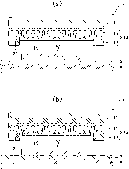
図2は、研磨ヘッドの要部断面図である。図2(a)に示すように、研磨ヘッドは、円形の定盤11を備えており、この定盤11の底面には、本発明の実施形態による保持具13が取り付けられている。保持具13は、発泡ポリウレタンで形成された保持パッド15と、保持パッド15の外周側に取り付けられた枠材17とを備えている。
FIG. 2 is a cross-sectional view of the main part of the polishing head. As shown in FIG. 2A, the polishing head includes a
保持パッド15は、円板形状を有しており、例えば、100%モジュラス(無発泡の樹脂シート2倍長に引っ張ったときに掛かる荷重を断面積で割った値)が20MPa以下のポリウレタン樹脂を湿式成膜することで形成されている。そして保持パッド15内部には無数の気泡19が形成されており、この気泡19によって保持パッド15のクッション性を向上させている。また、形成された発泡ポリウレタン樹脂の表面は、バフ処理が施されておらず、従って、その表面には、成膜時に形成されたスキン層が残っている。
The
枠材17は、保持パッド15と同一の外径を有するリング状の部材によって形成されており、その外周が保持パッド15の外周と一致するように、保持パッド15に固定されている。枠材17は、ウェハWを周方向から囲むことで、ウェハWが研磨ヘッド9と研磨パッド3との間から離脱するのを防止する。従って、枠材17の内径は、ウェハWの外径よりも大きい。また、枠材17の厚さは、ポケット深さがウェハWの厚さに対し−50μm〜+100μmの間になるように設定することが好ましく、−30μm〜+30μmの間に設定することがより好ましい。ポケット深さとは、枠材17の研磨面側から保持パッド15の保持面までの深さで、ウェハWが保持される部分の枠材17の厚さとなる。
The
また、保持パッド15には、枠材17を固定するための段部21が形成されている。段部21は、ウェハWと接触する保持面の周縁に沿って、保持面を囲むように形成されている。段部21は、内部に気泡19を有する保持パッド15の保持面を切削して形成したものであり、段部21の水平面及び垂直面の表面には、無数の気泡19が露出している。段部21の形状は、枠材17を段部21に配置したときに、枠材17の一部が保持面から突出するよう設計されている。枠材17の内周面は、段部21の垂直面に接するか、接しなくとも近接するように寸法決めされ、かつ形状決めされている。
Further, the holding
また、段部21の側面と枠材17の内周面が接着剤で接着されると、保持シートの枠材近傍のクッション性を制限されるため、図2(b)に示すように、枠材17を、段部21の水平面にのみ接着することが好ましい。また、ウェハWの端部の面取り加工を行う場合、SiCやサファイヤ等の高剛性ウェハWの研磨を行う場合、大孔径のウェハWの研磨を行う場合、回転数が大きく研磨速度が高い場合等には、ウェハWと枠材が衝突した際の衝撃が大きく、枠材が削られることで異物が生じる確率が高まる。この場合、研磨圧により異物がウェハWに強くこすりつけられ、ウェハに異物が付着したり、異物によりキズが生じたりすることがある。これを防止するために、枠材の内周面と段部21の側面との間隔は0mm〜15mmが好ましく、0.1mm〜10mmがより好ましく、0.1mm〜5mmが最も好ましい。枠材の内周面と段部21の側面との間隔が15mm以内であれば、端部形状を向上させることができる。一方で、枠材の内周面と段部21の側面との間隔が15mmを越すと、ウェハWに対する保持パッド15の平坦な保持・支持が不十分なものとなり、レート低下を招くと共に、ウェハ15が枠材内を揺動しやすく、保持面を平行に保てず、端部形状が悪化したり、保持パッド15からウェハWが外れたりする可能性が高まるため好ましくない。
Further, when the side surface of the stepped
枠材17を保持パッド15に固定する場合には、先ず、枠材17の水平面上に、所定の厚さ、例えば50μmの感熱接着シートを貼り合わせる。そして、段部21と感熱接着シートを貼り付けた枠材17を保持パッド15上に配置する。次いで、保持パッド15と枠材17が接着するよう加熱加圧すると、接着剤の一部は、軟化、或いは、溶融して気泡19内に入り込む。そして、例えば、厚さ30μmの層を形成できる程度の接着剤が気泡19内に入り込み、厚さ20μm程度の接着剤層が水平面上に形成される。このとき、接着剤は、段部21の水平面上に接着されており、垂直面には接着されていないので、枠材17は、水平面上に接着される。これにより、保持パッド15は、垂直方向では枠材17を接着力によって支持する。
When fixing the
また、段差21があることで、ウェハWの横方向の力に対しても段差で接着部にかかる力が分散するため好ましい。段部の深さは、40μm〜(L−150)μmであることが好ましい。段差21の深さは少なくとも40μm以上あることが好ましい。段差21の深さが40μm未満の場合は、研磨時にウェハWが枠材17と保持シート間の接着部に作用し、ワークが接着部に直接作用することで剥離を助長しやすくなる。更に、保持パッドの接着面での開口径が小さく接着剤の滲み込みが低下し、枠材17の接着面の強度が低下する。また、段差21を40μm以上とすることで、枠材17の水平方向のずれを保持パッドの段部で干渉することができ接着部のダメージをより低減できる。段差21が(L−150)μmより大きくなると、枠材17が保持パッドとの接着強度が向上する一方で、枠材17の保持パッドへの沈み込みが小さくなり研磨パッドへダメージを与える可能性がある。更に、ポケット深さを確保するために、枠材17の厚さを厚くする必要があり、枠材のコストが高くなり好ましくない。枠材17と円形の定盤11(保持定盤)間の保持パッド15の厚みは150μm以上、より好ましくは200μm以上とすることで枠材のクッション性が維持でき研磨パッドへのダメージをより低減させることができる。
Further, the presence of the
以上のように、本発明の実施形態によれば、ウェハWの離脱を防止する枠材17を、保持パッド15の周縁に沿って延びる段部21の水平面上に固定することができる。また、ウェハWと枠材17を1枚の保持パッド15で保持し、枠材17の内周面と保持パッド15が接着固定されていないため、研磨時の研磨応力が被研磨物直下及び枠材17の下に分散化させて被研磨物に加わる圧力を均一にすることができる。そして、これにより、ウェハWの周縁部における縁ダレを有効に防止することができる。
As described above, according to the embodiment of the present invention, the
また、枠材17を、段部21の水平面上に接着することにより、枠材17と、保持パッド15が固定される定盤11との間に、保持パッド15を介在させることができる。これにより、保持パッド15が枠材17のクッションとして機能し、研磨時に枠材17が垂直方向に移動することを許容でき、その結果、研磨圧の作用によって研磨パッド3が水平方向に回転する場合にも、研磨パッド3が枠材17に強く押し当てられ、研磨パッド3が損傷するのを防止することができる。さらに、枠材17を、段部21の水平面に接着することにより、枠材17と保持パッド15との接着面と、保持パッド15の保持面とを、保持パッド15の厚さ方向においてずらすことができる。これにより、研磨時に、ウェハWが、接着剤層に応力を加えてしまうことを防止し、枠材17の剥離を防止することができる。
In addition, the holding
また、内部に気泡19を有する保持パッド15を切削加工して気泡19を露出させ、そこに枠材17を接着することにより、接着剤が気泡19内部に入り込み、いわゆるアンカー効果によって枠材17の保持パッド15に対する接着力をより向上させることができる。
Further, by cutting the holding
なお、本実施形態において、被研磨物を保持する保持面にスキン層が形成されている場合について記載したが、本発明品はこれに限定されない。被研磨物の吸着保持力をコントロールする観点から、スキン層表面をバフ処理により開孔させたものを使用してもよい。バフ処理によりスキン層表面を開孔させたものは、枠材接着部の保持パッドの開孔をより大きなものとすることができ、より剥離強度を高めることができる。また、段差21を設けることで、段差がない保持材と比較し枠材周辺部の保持面でも弾性の変化が小さくなり端部ダレの低減に寄与できると共に段差により枠材の剥離を低減させることで、長期安定して研磨を行うことができる。しかしながら、保持面開孔部に研削屑や研磨屑が入りこみ、被研磨物に付着してしまう恐れがあるため、保持面をスキン層とすることで、保持パッドの立ち上がりを良くし、かつ被研磨物の裏面への異物の付着やキズの発生を低減することができる。
In addition, in this embodiment, although the case where the skin layer was formed in the holding surface holding a to-be-polished object was described, the product of this invention is not limited to this. From the viewpoint of controlling the adsorbing / holding power of the object to be polished, a material obtained by opening the skin layer surface by buffing may be used. In the case where the skin layer surface is opened by buffing, the opening of the holding pad of the frame material bonding portion can be made larger, and the peel strength can be further increased. In addition, by providing the
保持具13の構成として、保持パッド15の裏面側に基材としてPETなどの可撓性プラスチックシート部材を接着してもよく、これにより、保持定盤11への貼り付けや取り外し時の扱いが容易になる。また、保持具13を保持定盤11に取り付けるために、保持定盤11側に剥離紙を有する両面テープを設けていてもよい。このような構成とすることで、保持定盤11への装着が容易となる。
As a configuration of the
以下、本実施形態に従い製造した保持具の実施例について説明するが、本発明は実施例に限定されるものではない。 Hereinafter, although the Example of the holder manufactured according to this embodiment is described, this invention is not limited to an Example.
(実施例1)
湿式成膜法にて0.40mmに成膜し、発泡ポリウレタンシートを準備した。この発泡ポリウレタンシートの裏面(保持面とは反対側の面)側に支持基材としてPET製フィルムを、接着剤を介して貼り合わせた。次いで、PET製フィルムの反対面に保持定盤貼り合わせ用の片側離型紙つき両面テープを貼り合わせ保持シートを作製した。その後、保持シートを290mmφの円形に切り抜き、発泡ポリウレタンシートの保持面外周に、外周270.0mm、内周200.8mm(幅34.6mm)、深さ100μmの段部をNCルーターにより加工することで段部を形成した。一方、厚み0.87mmのガラスエポキシ板を外径260mmφ、内径201mmφ(幅29.5mm)のリング形状に切り抜き、外周部一面側の面取りを行った。次に、面取りしていない側の面に縦横300mm角、厚さ50μmの感熱性接着フィルムを仮接着して貼り合せた。その後リング状の枠材よりはみ出している余分な部分(外径260mmφより外側と内径201mmφより内側の部分)を切り取り、枠材を完成させた。段部を形成した保持シートの段部と接着フィルムを貼り合せている枠材の接着フィルム側とを位置合わせし積層させ、枠材上面より熱プレス加工することで、段部に開孔した発泡ポリウレタンシート内部に浸透するよう感熱性接着剤を溶融させ、接着させた。余分な保持シート(外周260mmφ以上)の部分をカットして取り除いて製品を完成させた。ポケット深さ(保持面から枠材が突出している高さ)を測定すると0.77mmであった。
Example 1
A wet polyurethane film was formed to 0.40 mm to prepare a foamed polyurethane sheet. A PET film as a supporting substrate was bonded to the back surface (surface opposite to the holding surface) side of the polyurethane foam sheet via an adhesive. Next, a holding sheet was prepared by laminating a double-sided tape with one-side release paper for holding platen bonding to the opposite surface of the PET film. After that, the holding sheet is cut out into a circle of 290 mmφ, and the outer peripheral surface of the foamed polyurethane sheet is processed with an NC router on the outer periphery 270.0 mm, inner periphery 200.8 mm (width 34.6 mm), depth 100 μm. A step was formed. On the other hand, a glass epoxy plate having a thickness of 0.87 mm was cut into a ring shape having an outer diameter of 260 mmφ and an inner diameter of 201 mmφ (width of 29.5 mm), and chamfered on one side of the outer peripheral portion. Next, a 300 mm square length and 50 μm thick heat-sensitive adhesive film was temporarily bonded and bonded to the non-chamfered surface. Thereafter, an excess portion protruding from the ring-shaped frame material (a portion outside the outer diameter of 260 mmφ and a portion inside the inner diameter of 201 mmφ) was cut off to complete the frame material. Positioning and laminating the stepped part of the holding sheet that forms the stepped part and the adhesive film side of the frame material to which the adhesive film is bonded, and then hot-pressing from the upper surface of the frame material, foaming that opens in the stepped part The heat sensitive adhesive was melted and adhered so as to penetrate into the polyurethane sheet. An excess holding sheet (outer circumference of 260 mmφ or more) was cut and removed to complete the product. The pocket depth (height at which the frame member protrudes from the holding surface) was measured to be 0.77 mm.
(実施例2)
湿式成膜法にて0.56mmに成膜し、バフ処理量を0.16mmとしてバフ番手♯180のサンドペーパーを用いて発泡ポリウレタンシートのスキン層側をバフ処理し保持面を開孔させ0.40mm厚みの発泡ポリウレタンシートを準備した以外は実施例1と同様にして段部を有する保持具を製造した。ポケット深さを測定すると0.77mmであった。
(Example 2)
A film is formed to a thickness of 0.56 mm by a wet film formation method, the buff treatment amount is 0.16 mm, and the skin layer side of the foamed polyurethane sheet is buffed using a sandpaper of buff count # 180 to open the holding surface to 0. A holder having a stepped portion was manufactured in the same manner as in Example 1 except that a foamed polyurethane sheet having a thickness of 40 mm was prepared. The pocket depth was measured to be 0.77 mm.
(実施例3)
発泡ポリウレタンシートの保持面外周に外周270.0mm、内周181.0mm(幅44.5mm)、深さ100μmの段部を形成し、枠材の内周面と段部の側面との間隔が10mmとなるよう段部を形成した以外は実施例1と同様にして段部を有する保持具を製造した。ポケット深さを測定すると0.77mmであった。
Example 3
A step portion having an outer periphery of 270.0 mm, an inner periphery of 181.0 mm (width of 44.5 mm), and a depth of 100 μm is formed on the outer periphery of the holding surface of the polyurethane foam sheet, and the distance between the inner peripheral surface of the frame member and the side surface of the step portion is A holder having a stepped portion was manufactured in the same manner as in Example 1 except that the stepped portion was formed to be 10 mm. The pocket depth was measured to be 0.77 mm.
(比較例1)
実施例1のスキン層を有する0.40mm厚みの発泡ポリウレタンシートを用い、段部を形成しないこと、及びガラスエポキシ板の厚みを0.72mmとした以外は実施例1と同様に保持具を製造した。ポケット深さを測定すると0.77mmであった。
(Comparative Example 1)
A holder was manufactured in the same manner as in Example 1 except that a foamed polyurethane sheet having a skin layer of Example 1 having a thickness of 0.40 mm was used, no step was formed, and the thickness of the glass epoxy plate was 0.72 mm. did. The pocket depth was measured to be 0.77 mm.
(比較例2)
実施例2のバフにて表面を開孔させた0.40mm厚みの発泡ポリウレタンシートを用い、段部を形成しないこと、及びガラスエポキシ板の厚みを0.77mmとした以外は実施例2と同様に保持具を製造した。ポケット深さを測定すると0.77mmであった。
(Comparative Example 2)
The same as Example 2 except that a foamed polyurethane sheet having a thickness of 0.40 mm, the surface of which was opened with the buff of Example 2, was not formed and the thickness of the glass epoxy plate was 0.77 mm. The holder was manufactured. The pocket depth was measured to be 0.77 mm.
(比較例3)
段部の深さを30μmとし、ガラスエポキシ板の厚みを0.81mmとした以外は実施例1と同様に保持具を製造した。ポケット深さを測定すると0.77mmであった。
(Comparative Example 3)
A holder was manufactured in the same manner as in Example 1 except that the depth of the stepped portion was 30 μm and the thickness of the glass epoxy plate was 0.81 mm. The pocket depth was measured to be 0.77 mm.
(比較例4)
段部の深さを300μmとし、ガラスエポキシ板の厚みを1.06mmとした以外は実施例1と同様に保持具を製造した。ポケット深さを測定すると0.77mmであった。
(Comparative Example 4)
A holder was manufactured in the same manner as in Example 1 except that the depth of the stepped portion was 300 μm and the thickness of the glass epoxy plate was 1.06 mm. The pocket depth was measured to be 0.77 mm.
(比較例5)
発泡ポリウレタンシートの保持面外周に外周270.0mm、内周157.0mm(幅56.5mm)、深さ100μmの段部を形成し、枠材の内周面と段部の側面との間隔が22mmとなるよう段部を形成した以外は実施例1と同様にして段部を有する保持具を製造した。ポケット深さを測定すると0.77mmであった。
(Comparative Example 5)
A step portion having an outer periphery of 270.0 mm, an inner periphery of 157.0 mm (width of 56.5 mm), and a depth of 100 μm is formed on the outer periphery of the holding surface of the polyurethane foam sheet, and the distance between the inner peripheral surface of the frame member and the side surface of the step portion is A holder having a stepped portion was manufactured in the same manner as in Example 1 except that the stepped portion was formed to be 22 mm. The pocket depth was measured to be 0.77 mm.
(研磨性能評価)
次に、各実施例および比較例の保持具を用いたシリコンウェハの研磨加工を、以下の条件で行い、研磨レート、端部ダレ、剥離強度により保持具性能を評価した。研磨レートは研磨前後の重量の差により算出した。端部ダレは、被研磨物の周縁部が中心部より過度に研磨加工されることで生じ、平坦性を評価するための測定項目の1つである。測定方法としては、例えば、光学式表面粗さ計にて外周端部から中心に向かい0.3mmの位置より半径方向に2mmの範囲で2次元プロファイル像を得る。得られた2次元プロファイル像において、半径方向をX軸、厚み方向をY軸としたときに、外周端部からX=0.5mmおよびX=1.5mmの座標位置のY軸の値がY=0となるようにレベリング補正した。このときの2次元プロファイル像のX=0.5〜1.5mm間におけるPV値を相対値で表した。端部ダレの測定には、表面粗さ測定機(Zygo社製、型番New View 5022)を使用した。また剥離強度は、各実施例および比較例の保持具において、枠材と保持シート間の剥離強度を180度剥離試験にて剥離強度測定を行った。剥離強度測定は、枠材剥離による寿命を間接的に推測することができ、枠材と保持シートが剥がれにくく剥離強度が大きいほど保持具の寿命を向上させることができる。なお、各研磨結果及び剥離強度測定結果は、比較例1を1.0としてその比で示している。測定結果を下表1に示す。
(Polishing performance evaluation)
Next, the polishing process of the silicon wafer using the holders of Examples and Comparative Examples was performed under the following conditions, and the holder performance was evaluated based on the polishing rate, the edge sagging, and the peel strength. The polishing rate was calculated from the difference in weight before and after polishing. The end sagging occurs when the peripheral edge of the object to be polished is excessively polished from the center, and is one of the measurement items for evaluating the flatness. As a measuring method, for example, a two-dimensional profile image is obtained within a range of 2 mm in the radial direction from a position of 0.3 mm from the outer peripheral end to the center by an optical surface roughness meter. In the obtained two-dimensional profile image, when the radial direction is the X axis and the thickness direction is the Y axis, the values of the Y axis at the coordinate positions of X = 0.5 mm and X = 1.5 mm from the outer peripheral end are Y Leveling correction was performed so that = 0. The PV value between X = 0.5 and 1.5 mm of the two-dimensional profile image at this time was expressed as a relative value. A surface roughness measuring machine (manufactured by Zygo, model number New View 5022) was used to measure the edge sagging. The peel strength was measured by a 180 degree peel test for the peel strength between the frame member and the holding sheet in the holders of the examples and comparative examples. In the peel strength measurement, the life due to the peeling of the frame material can be indirectly estimated, and the life of the holder can be improved as the peel strength of the frame material and the holding sheet is difficult to peel off. In addition, each grinding | polishing result and peeling strength measurement result have shown the comparative example 1 by 1.0, and are shown by the ratio. The measurement results are shown in Table 1 below.
(研磨条件)
使用研磨機:不二越株式会社製、MCP−150X
研磨パッド:フジボウ愛媛株式会社製、POLYPAS CM4301
回転数:(定盤)100r/m、(トップリング)75r/m
研磨圧力:330g/cm2
揺動幅:10mm(揺動中心値より200mm)
揺動移動:1mm/min
研磨剤:Nalco社製、品番2350(2350原液:水=1:9の混合液を使用)
被研磨物:8インチφシリコンウェハ(厚み780μm)
研磨時間:20分間
(Polishing conditions)
Polishing machine used: Fujikoshi Co., Ltd., MCP-150X
Polishing pad: Fujibow Atago Co., Ltd., POLYPAS CM4301
Rotation speed: (Surface plate) 100r / m, (Top ring) 75r / m
Polishing pressure: 330 g / cm 2
Swing width: 10mm (200mm from the swing center value)
Swing movement: 1 mm / min
Abrasive: manufactured by Nalco, product number 2350 (2350 stock solution: water = 1: 9 mixed solution used)
Object to be polished: 8 inch φ silicon wafer (thickness: 780 μm)
Polishing time: 20 minutes
〔評価結果〕
実施例1では、段差によるワークの端部への影響度が低減され端部ダレは半減し、枠材とウェハの接触が抑制されたため剥離が改善され、剥離強度は比較例1の1.7倍と改善がみられた。
〔Evaluation results〕
In Example 1, the influence of the step on the edge of the workpiece is reduced, the edge sag is halved, the contact between the frame material and the wafer is suppressed, and the peeling is improved. The peeling strength is 1.7 of Comparative Example 1. Doubled and improved.
実施例2では、実施例1よりも段部に開孔した孔径が大きく、接着剤の存在量が増えたため剥離強度が比較例1より1.8倍向上した。一方、保持表面が開孔しているため、研削屑等の影響かパーティクル付着があり、立ち上がりに実施例1の2倍の時間を要した。 In Example 2, since the hole diameter opened in the step portion was larger than that in Example 1 and the amount of the adhesive was increased, the peel strength was improved 1.8 times compared with Comparative Example 1. On the other hand, since the holding surface was open, there was an influence of grinding dust or the like, or particle adhesion, and it took twice as long as in Example 1 to rise.
実施例3では、実施例1よりも段部の幅が広く、ウェハの最外周が段部上にあり保持パッドと接触していないため、ウェハ最外周部の端部ダレが少なくなった。 In Example 3, the width of the stepped portion was wider than that in Example 1, and the outermost periphery of the wafer was on the stepped portion and was not in contact with the holding pad.
比較例1では、段部が無いため保持パッドの圧縮変形が枠材内周に集中し、端部ダレが実施例の2倍悪く、実施例1より剥離強度は低く、剥離しやすい保持材であると考えられる。 In Comparative Example 1, since there is no stepped portion, the compression deformation of the holding pad is concentrated on the inner periphery of the frame material, the end sagging is twice as bad as the Example, the peeling strength is lower than that of Example 1, and the holding material is easy to peel It is believed that there is.
比較例2は段部が無いため保持パッドの圧縮変形が枠材内周に集中し、端部ダレが実施例の2倍悪い結果となった。発泡ポリウレタンシートが開孔しているため、接着強度は実施例1と同等であったが、枠材と発泡ポリウレタンシートの接着部にウェハが直接作用することで剥離が発生しやすいものと考えられる。保持表面が開孔しているため、実施例2と同様にパーティクル付着があり、立ち上がりに実施例1の2倍の時間を要した。 In Comparative Example 2, since there was no stepped portion, the compression deformation of the holding pad was concentrated on the inner periphery of the frame material, and the end sagging was twice as bad as that of the example. Since the foamed polyurethane sheet is perforated, the adhesive strength was the same as in Example 1. However, it is considered that peeling is likely to occur when the wafer acts directly on the bonded portion between the frame material and the foamed polyurethane sheet. . Since the holding surface was open, there was particle adhesion as in Example 2, and it took twice as long as in Example 1 to rise.
比較例3では、段部深さが不十分であったため、バフ厚みも少なく、開孔径が小さくなることで、感圧接着剤の滲み込みが悪化し、剥離強度は実施例1,2よりも低下している。また、端部ダレも実施例より劣るものであった。 In Comparative Example 3, since the step depth was insufficient, the buff thickness was small and the opening diameter was small, so that the penetration of the pressure-sensitive adhesive deteriorated, and the peel strength was higher than in Examples 1 and 2. It is falling. Moreover, the edge part sagging was also inferior to an Example.
比較例4では、段部深さが大きく、剥離強度は実施例1,2と同程度であったが、枠材下の発泡ポリウレタンシート厚みが十分でなく、研磨加工中、実施例と比べ枠材の沈み込みが少なくなる分、ワークへの研磨圧が低下するためか、端部形状には優れるが、レートの低下が発生した。また、研磨パッドと枠材の接触が強くなり、枠材の剥離及び研磨パッドの損傷も早くなることが推測される。 In Comparative Example 4, the step depth was large and the peel strength was about the same as in Examples 1 and 2, but the thickness of the foamed polyurethane sheet under the frame was not sufficient, and the frame was compared with the Example during polishing. The end shape is excellent, but the rate is reduced, because the polishing pressure on the workpiece is reduced as the material sinks less. Further, it is estimated that the contact between the polishing pad and the frame material becomes strong, and the peeling of the frame material and the damage to the polishing pad are accelerated.
比較例5では、枠材の内周面と段部の側面との間隔が広すぎたため、レートが低下し、保持パッドの保持力が不足したためか、端部形状が悪化した。 In Comparative Example 5, because the distance between the inner peripheral surface of the frame member and the side surface of the stepped portion was too wide, the rate was lowered and the holding force of the holding pad was insufficient, or the end shape deteriorated.
13 保持具
15 保持パッド
17 枠材
19 気泡
21 段部
13
Claims (4)
内部に多数の気泡を有する発泡ポリウレタン製の保持パッドと、
前記保持パッドの保持面の周縁に沿って、当該保持面を囲む枠材と、を備え、
前記保持パッドは、保持面の周縁を所定の深さだけ切削して形成され少なくとも水平面に気泡が露出している段部を備え、
前記枠材は、前記段部の水平面上において前記保持パッドに感熱性接着剤層を介して接着され、内周面が、前記段部の垂直面に対向するように、前記保持パッドに固定されている、ことを特徴とする保持具。 A holding tool for holding an object to be polished when polishing the object,
A holding pad made of polyurethane foam having a large number of bubbles inside, and
A frame member surrounding the holding surface along the periphery of the holding surface of the holding pad,
The holding pad includes a step portion formed by cutting the peripheral edge of the holding surface by a predetermined depth, and at least air bubbles are exposed on a horizontal plane ,
The frame member is bonded to the holding pad via a heat-sensitive adhesive layer on the horizontal surface of the stepped portion, and is fixed to the holding pad so that the inner peripheral surface faces the vertical surface of the stepped portion. and that, you wherein the retainer.
内部に多数の気泡を有する発泡ポリウレタン製の保持パッドを準備するステップと、
前記保持パッドの保持面の周縁を所定の深さだけ切削して少なくとも水平面に気泡が露出している段部を形成するステップと、
この保持パッドの保持面の周縁に沿って、当該保持面を囲む枠材を感熱性接着剤により固定するステップと、を備え、
前記枠材は、前記段部の水平面上において前記保持パッドに接着され、内周面が、前記段部の垂直面に対向するように、前記保持パッドに固定されていることを特徴とする、保持具の製造方法。 A method of manufacturing a holder for holding an object to be polished when polishing the object,
Preparing a retaining pad made of polyurethane foam having a large number of bubbles inside;
Cutting a peripheral edge of the holding surface of the holding pad by a predetermined depth to form a stepped portion in which bubbles are exposed at least in a horizontal plane ;
Fixing the frame material surrounding the holding surface with a heat-sensitive adhesive along the peripheral edge of the holding surface of the holding pad, and
The frame member is bonded to the holding pad on the horizontal surface of the stepped portion, and the inner peripheral surface is fixed to the holding pad so as to face the vertical surface of the stepped portion, A method for manufacturing a holder.
Priority Applications (3)
| Application Number | Priority Date | Filing Date | Title |
|---|---|---|---|
| JP2014169286A JP6439963B2 (en) | 2014-08-22 | 2014-08-22 | Holding tool and manufacturing method thereof |
| KR1020177007366A KR102404979B1 (en) | 2014-08-22 | 2015-08-24 | Holder and manufacturing method thereof |
| PCT/JP2015/073684 WO2016027903A1 (en) | 2014-08-22 | 2015-08-24 | Holder and manufacturing method thereof |
Applications Claiming Priority (1)
| Application Number | Priority Date | Filing Date | Title |
|---|---|---|---|
| JP2014169286A JP6439963B2 (en) | 2014-08-22 | 2014-08-22 | Holding tool and manufacturing method thereof |
Publications (2)
| Publication Number | Publication Date |
|---|---|
| JP2016043446A JP2016043446A (en) | 2016-04-04 |
| JP6439963B2 true JP6439963B2 (en) | 2018-12-19 |
Family
ID=55350842
Family Applications (1)
| Application Number | Title | Priority Date | Filing Date |
|---|---|---|---|
| JP2014169286A Active JP6439963B2 (en) | 2014-08-22 | 2014-08-22 | Holding tool and manufacturing method thereof |
Country Status (3)
| Country | Link |
|---|---|
| JP (1) | JP6439963B2 (en) |
| KR (1) | KR102404979B1 (en) |
| WO (1) | WO2016027903A1 (en) |
Families Citing this family (1)
| Publication number | Priority date | Publication date | Assignee | Title |
|---|---|---|---|---|
| JP7212242B2 (en) * | 2018-08-21 | 2023-01-25 | 富士紡ホールディングス株式会社 | Holder for object to be polished |
Family Cites Families (11)
| Publication number | Priority date | Publication date | Assignee | Title |
|---|---|---|---|---|
| JP2632738B2 (en) | 1990-04-27 | 1997-07-23 | 信越半導体 株式会社 | Packing pad and method for polishing semiconductor wafer |
| JPH10113859A (en) * | 1996-10-08 | 1998-05-06 | Oki Electric Ind Co Ltd | Method for chemically and mechanically polishing semiconductor wafer |
| JP2004319584A (en) * | 2003-04-11 | 2004-11-11 | Nihon Micro Coating Co Ltd | Polishing pad and its manufacturing method |
| JP2007173815A (en) * | 2005-12-20 | 2007-07-05 | Siltron Inc | Silicon wafer polishing machine, retaining assembly used for same, and method of correcting flatness of silicon wafer |
| JP2006102940A (en) | 2006-01-10 | 2006-04-20 | Nihon Micro Coating Co Ltd | Polishing pad and its manufacturing method |
| JP2009160706A (en) * | 2008-01-09 | 2009-07-23 | Nitta Haas Inc | Work piece holding frame member and work piece holding tool |
| JP5935993B2 (en) | 2012-06-19 | 2016-06-15 | 富士紡ホールディングス株式会社 | Retainer |
| JP6004329B2 (en) * | 2012-08-10 | 2016-10-05 | 富士紡ホールディングス株式会社 | Holding tool and manufacturing method thereof |
| JP5968179B2 (en) * | 2012-09-28 | 2016-08-10 | 富士紡ホールディングス株式会社 | Holding pad |
| JP6032643B2 (en) * | 2012-12-03 | 2016-11-30 | 株式会社岡本工作機械製作所 | Backing material and substrate carrier head structure using the same |
| JP6567420B2 (en) | 2013-09-11 | 2019-08-28 | 富士紡ホールディングス株式会社 | Polishing pad and manufacturing method thereof |
-
2014
- 2014-08-22 JP JP2014169286A patent/JP6439963B2/en active Active
-
2015
- 2015-08-24 KR KR1020177007366A patent/KR102404979B1/en active IP Right Grant
- 2015-08-24 WO PCT/JP2015/073684 patent/WO2016027903A1/en active Application Filing
Also Published As
| Publication number | Publication date |
|---|---|
| KR20170045266A (en) | 2017-04-26 |
| KR102404979B1 (en) | 2022-06-07 |
| JP2016043446A (en) | 2016-04-04 |
| WO2016027903A1 (en) | 2016-02-25 |
Similar Documents
| Publication | Publication Date | Title |
|---|---|---|
| TWI421934B (en) | Method for polishing a semiconductor wafer | |
| US10189142B2 (en) | Method for polishing a semiconductor wafer | |
| US9991110B2 (en) | Method for manufacturing semiconductor wafer | |
| KR101152462B1 (en) | Method for polishing the edge of a semiconductor wafer | |
| TWI523096B (en) | Wafer polishing tool and method for wafer polishing | |
| JP6439963B2 (en) | Holding tool and manufacturing method thereof | |
| US20100112905A1 (en) | Wafer head template for chemical mechanical polishing and a method for its use | |
| JP4793680B2 (en) | Semiconductor wafer polishing method | |
| JP6004329B2 (en) | Holding tool and manufacturing method thereof | |
| JP2003236743A5 (en) | ||
| JP5457897B2 (en) | Retaining material | |
| JP2016049606A (en) | Polishing device | |
| JP6717706B2 (en) | Wafer surface treatment equipment | |
| JP6616171B2 (en) | Polishing apparatus and polishing processing method | |
| JP2019058955A (en) | Polishing head and manufacturing method of the same | |
| JP6432080B2 (en) | Holding tool and manufacturing method thereof | |
| JP7082748B2 (en) | Abrasive Pad Fixtures and Abrasive Pads | |
| JP2000042910A (en) | Workpiece holder for polishing | |
| JP2015205389A (en) | Polishing pad and polishing device | |
| JP6843553B2 (en) | Wafer surface treatment method | |
| JP2008238348A (en) | Workpiece holding material | |
| JP2023133815A (en) | polishing body | |
| JP4598551B2 (en) | Workpiece holding material and method for manufacturing workpiece holding material | |
| JP6698475B2 (en) | Wafer surface treatment equipment | |
| JPH0731260U (en) | Object to be polished |
Legal Events
| Date | Code | Title | Description |
|---|---|---|---|
| RD04 | Notification of resignation of power of attorney |
Free format text: JAPANESE INTERMEDIATE CODE: A7424 Effective date: 20170425 |
|
| A621 | Written request for application examination |
Free format text: JAPANESE INTERMEDIATE CODE: A621 Effective date: 20170706 |
|
| A131 | Notification of reasons for refusal |
Free format text: JAPANESE INTERMEDIATE CODE: A131 Effective date: 20180704 |
|
| A521 | Request for written amendment filed |
Free format text: JAPANESE INTERMEDIATE CODE: A523 Effective date: 20180903 |
|
| TRDD | Decision of grant or rejection written | ||
| A01 | Written decision to grant a patent or to grant a registration (utility model) |
Free format text: JAPANESE INTERMEDIATE CODE: A01 Effective date: 20181024 |
|
| A61 | First payment of annual fees (during grant procedure) |
Free format text: JAPANESE INTERMEDIATE CODE: A61 Effective date: 20181107 |
|
| R150 | Certificate of patent or registration of utility model |
Ref document number: 6439963 Country of ref document: JP Free format text: JAPANESE INTERMEDIATE CODE: R150 |
|
| R250 | Receipt of annual fees |
Free format text: JAPANESE INTERMEDIATE CODE: R250 |
|
| R250 | Receipt of annual fees |
Free format text: JAPANESE INTERMEDIATE CODE: R250 |
|
| R250 | Receipt of annual fees |
Free format text: JAPANESE INTERMEDIATE CODE: R250 |