JP6438552B2 - Method and apparatus for recapturing an object on a glass slide - Google Patents

Method and apparatus for recapturing an object on a glass slide Download PDF

Info

Publication number
JP6438552B2
JP6438552B2 JP2017182321A JP2017182321A JP6438552B2 JP 6438552 B2 JP6438552 B2 JP 6438552B2 JP 2017182321 A JP2017182321 A JP 2017182321A JP 2017182321 A JP2017182321 A JP 2017182321A JP 6438552 B2 JP6438552 B2 JP 6438552B2
Authority
JP
Japan
Prior art keywords
slide
contact
potentiometer
linear potentiometer
stage
Prior art date
Legal status (The legal status is an assumption and is not a legal conclusion. Google has not performed a legal analysis and makes no representation as to the accuracy of the status listed.)
Active
Application number
JP2017182321A
Other languages
Japanese (ja)
Other versions
JP2018097354A (en
Inventor
エー. ローブ,ウィリアム
エー. ローブ,ウィリアム
Current Assignee (The listed assignees may be inaccurate. Google has not performed a legal analysis and makes no representation or warranty as to the accuracy of the list.)
Individual
Original Assignee
Individual
Priority date (The priority date is an assumption and is not a legal conclusion. Google has not performed a legal analysis and makes no representation as to the accuracy of the date listed.)
Filing date
Publication date
Application filed by Individual filed Critical Individual
Publication of JP2018097354A publication Critical patent/JP2018097354A/en
Application granted granted Critical
Publication of JP6438552B2 publication Critical patent/JP6438552B2/en
Active legal-status Critical Current
Anticipated expiration legal-status Critical

Links

Images

Classifications

    • GPHYSICS
    • G02OPTICS
    • G02BOPTICAL ELEMENTS, SYSTEMS OR APPARATUS
    • G02B21/00Microscopes
    • G02B21/24Base structure
    • G02B21/26Stages; Adjusting means therefor
    • GPHYSICS
    • G02OPTICS
    • G02BOPTICAL ELEMENTS, SYSTEMS OR APPARATUS
    • G02B21/00Microscopes
    • G02B21/34Microscope slides, e.g. mounting specimens on microscope slides
    • GPHYSICS
    • G02OPTICS
    • G02BOPTICAL ELEMENTS, SYSTEMS OR APPARATUS
    • G02B21/00Microscopes
    • G02B21/36Microscopes arranged for photographic purposes or projection purposes or digital imaging or video purposes including associated control and data processing arrangements
    • G02B21/365Control or image processing arrangements for digital or video microscopes

Landscapes

  • Physics & Mathematics (AREA)
  • Chemical & Material Sciences (AREA)
  • Analytical Chemistry (AREA)
  • General Physics & Mathematics (AREA)
  • Optics & Photonics (AREA)
  • Engineering & Computer Science (AREA)
  • Multimedia (AREA)
  • Computer Vision & Pattern Recognition (AREA)
  • Microscoopes, Condenser (AREA)
  • Length Measuring Devices With Unspecified Measuring Means (AREA)

Description

[0001] 本発明は、顕微鏡の分野、及び、スライド上の対象の位置を記録するために顕微鏡の視野に対象又は標本を位置付けることに関する。特に本発明の態様は、スライド上での対象の位置を位置決めするように、とりわけ、さらなる調査のためにより容易に対象を再捕捉するように、スライドガラスに作動可能に接続されるリニアポテンショメータを採用する。 [0001] The present invention relates to the field of microscopy and to positioning an object or specimen in the field of view of a microscope to record the position of the object on a slide. In particular, aspects of the present invention employ a linear potentiometer operably connected to the glass slide to locate the object on the slide, and more particularly to recapture the object more easily for further investigation. To do.

[0002] 広範囲の分野、例えば、医療、生物学、薬理学、遺伝学、(全てのレベルの学校を含む)教育機関及び科学捜査の調査者は、光学、デジタル、電子及び原子力顕微鏡を含む顕微鏡をしばしば使用して、例えば微生物、血液細胞、素材、物体などの標本を調査する。しかしながら、既存の顕微鏡の拡大倍率により、一度対象又は標本が顕微鏡の視野に位置付けられると、例えば同僚又は他の調査者が検査のために対象を視野に再び位置付け又は再捕捉するのはしばしば困難である。 [0002] A wide range of fields such as medical, biology, pharmacology, genetics, educational institutions (including all levels of schools) and forensic investigators, microscopes including optical, digital, electronic and atomic force microscopes Are often used to examine specimens of, for example, microorganisms, blood cells, materials and objects. However, due to the magnification of existing microscopes, once an object or specimen has been positioned in the microscope field of view, it is often difficult for a colleague or other investigator to reposition or recapture the object in the field of view for inspection, for example. is there.

[0003] 顕微鏡の使用のこれらの特定の欠点に対処する多くの先行技術の試みがなされてきたが、有効性及び/又は再現性の欠如がみられた。例えば、Christovの米国特許第4,374,327号は、電子顕微鏡のステージの位置決め方法を開示する。Younの米国特許第9,001,421号は、顕微鏡の拡大を調整する装置を開示する。Younの装置は、回転可能な調整装置に取り付けられたポテンショメータを含む。Pageの米国特許第3,727,051号は、自動的に調整可能なステージを有する電子顕微鏡を開示する。Phillipsの米国特許第4,442,388号は、ポテンショメータを使用するX−Yワークステージポジショナを有する半導体ワークピースのためのワークステージを開示する。Brockman,et al.の米国特許第3,779,400号は、リニアポテンショメータの使用によるツールの位置決め方法及び装置を開示する。Mori,et al.の米国特許第5,780,853号は、ステージを操縦するのにポテンショメータを使用するジョイスティックを有する電子顕微鏡を開示する。Gibbsの米国特許第4,833,382号は、スライドガラスの位置決めシステムを開示する。 [0003] Although many prior art attempts have been made to address these specific shortcomings of using microscopes, there has been a lack of effectiveness and / or reproducibility. For example, Christov, US Pat. No. 4,374,327 discloses a method for positioning an electron microscope stage. Young, US Pat. No. 9,001,421, discloses an apparatus for adjusting the magnification of a microscope. The Young device includes a potentiometer attached to a rotatable adjustment device. Page, US Pat. No. 3,727,051 discloses an electron microscope having an automatically adjustable stage. Phillips US Pat. No. 4,442,388 discloses a work stage for a semiconductor workpiece having an XY work stage positioner using a potentiometer. Blockman, et al. U.S. Pat. No. 3,779,400 discloses a tool positioning method and apparatus by use of a linear potentiometer. Mori, et al. U.S. Pat. No. 5,780,853 discloses an electron microscope having a joystick that uses a potentiometer to steer the stage. Gibbs U.S. Pat. No. 4,833,382 discloses a glass positioning system.

[0004] しかしながら、これらの及び他の先行技術が顕微鏡の使用を容易にするよう試みているにもかかわらず、顕微鏡で見る対象の再捕捉の正確性を容易にして向上させる改善された方法、システム及び装置を提供する当業界のニーズが依然としてある。 [0004] However, despite these and other prior art attempts to facilitate the use of microscopes, improved methods that facilitate and improve the accuracy of recapture of objects viewed with a microscope, There remains a need in the industry to provide systems and devices.

[0005] 本発明の態様は、顕微鏡の検査下の対象又は標本の正確な位置付け及び/又は再位置決めのための適切な機械的結合具及びリニアポテンショメータを含む顕微鏡ステージの位置決め方法、機器及び装置を採用する。 [0005] Aspects of the present invention provide a method, apparatus and apparatus for positioning a microscope stage including a suitable mechanical coupler and linear potentiometer for accurate positioning and / or repositioning of an object or specimen under examination of a microscope. adopt.

[0006] 本発明の一実施形態は、収容部と、収容部内に位置し、信号を出力するように適応されたリニアポテンショメータと、収容部内に摺動可能に取り付けられ、リニアポテンショメータに選択的に接触するように適応された接点であって、リニアポテンショメータ上の接点の位置が、リニアポテンショメータにより出力される信号を決定する接点と、接点に作動可能に接続された第1端部、及び、対象を有するスライドに作動可能に接続された第2端部を有し、スライドは第1方向に移動可能である、結合具と、リニアポテンショメータにより出力された信号を受信し、信号を用いて移動可能なスライドの位置を判断するように適応された受信器と、を備える又は含む、顕微鏡の視野内にスライド上の対象を位置付ける機器である。一態様では、リニアポテンショメータが膜タイプリニアポテンショメータであってもよい。 [0006] One embodiment of the present invention includes an accommodating portion, a linear potentiometer that is positioned in the accommodating portion and adapted to output a signal, and is slidably mounted in the accommodating portion, and is selectively attached to the linear potentiometer. A contact adapted to contact, wherein the position of the contact on the linear potentiometer determines a signal output by the linear potentiometer, a first end operably connected to the contact, and an object A slide having a second end operably connected to the slide, the slide being movable in a first direction, receiving a signal output by a coupling and a linear potentiometer, and movable using the signal An apparatus for positioning an object on a slide within a microscope field of view, comprising or including a receiver adapted to determine the position of the correct slide. In one aspect, the linear potentiometer may be a membrane type linear potentiometer.

[0007] 別の態様では、機器は、収容部内を移動するとともに接点を保持するように適応されたスライダブロックをさらに備え、結合具の第1端部がスライダブロックに接続される。別の態様では、収容部は、スライダブロックを受け入れるように適応されたチャネルを備える。一態様では、結合具は、少なくとも1つのロッドを備える。 [0007] In another aspect, the device further comprises a slider block adapted to move within the housing and to hold the contact, and the first end of the coupler is connected to the slider block. In another aspect, the receptacle comprises a channel adapted to receive the slider block. In one aspect, the coupler comprises at least one rod.

[0008] 別の態様では、収容部が第1収容部を備え、リニアポテンショメータが第1リニアポテンショメータを備え、信号が第1信号を備え、接点が第1接点を備え、及び、結合具が第1結合具を備え、機器が、第2収容部と、第2収容部内に位置し、第2信号を出力するように適応された第2リニアポテンショメータと、第2収容部に摺動可能に取り付けられ、第2リニアポテンショメータに選択的に接触するように適応された第2接点であって、第2リニアポテンショメータ上の第2接点の位置が、第2リニアポテンショメータにより出力される第2信号を決定する第2接点と、第2接点に作動可能に接続された第1端部と、スライドに作動可能に接続された第2端部と、を有し、スライドは、第1方向と異なる第2方向に移動可能である、第2結合具をさらに含む。 [0008] In another aspect, the housing portion comprises a first housing portion, the linear potentiometer comprises a first linear potentiometer, the signal comprises a first signal, the contact comprises a first contact, and the coupler comprises a first A first coupling device, wherein the device is slidably attached to the second housing portion, a second linear potentiometer located in the second housing portion and adapted to output a second signal; A second contact adapted to selectively contact the second linear potentiometer, wherein the position of the second contact on the second linear potentiometer determines a second signal output by the second linear potentiometer. A second end that is operatively connected to the second contact, and a second end that is operably connected to the slide, wherein the slide is second different from the first direction. Can move in the direction Further comprising a second coupler.

[0009] 一態様では、受信器はさらに、第1信号及び第2信号を受信し、第1信号に関する第1出力、及び、第2信号に関する第2出力を表示するように適応されてもよい。一態様では、受信器はさらに、第2出力を第1出力と区別するため、第2信号に対応する数字の表示を5000増加するように適応されてもよい。別の態様では、受信器は、スライドの検出された方向に応じて少なくとも第2出力の極性を変更するように適応されてもよい。 [0009] In an aspect, the receiver may be further adapted to receive the first signal and the second signal and display a first output for the first signal and a second output for the second signal. . In one aspect, the receiver may be further adapted to increase the number display corresponding to the second signal by 5000 to distinguish the second output from the first output. In another aspect, the receiver may be adapted to change the polarity of at least the second output in response to the detected direction of the slide.

[0010] 別の態様では、スライドに作動可能に接続された結合具の第2端部を、スライドを保持する顕微鏡ステージに作動可能に接続してもよく、又は、スライドを保持するスライドガラスホルダに作動可能に接続してもよい。 [0010] In another aspect, the second end of the coupler operably connected to the slide may be operably connected to a microscope stage that holds the slide, or a slide glass holder that holds the slide May be operatively connected.

[0011]さらなる態様で、機器は、例えば導電ストリップに係合するように適応された電気接点を有するスライド位置決めシステムを有してもよい。 [0011] In a further aspect, the instrument may have a slide positioning system with electrical contacts adapted to engage the conductive strip, for example.

[0012] 本発明の他の実施形態は、接点を顕微鏡のステージ上のスライドに作動可能に接続することと、スライドを移動させ、それによって接点を移動させ、スライド上の対象が顕微鏡の視野内に現れることと、顕微鏡の視野内に対象を目に見えるように位置付けることと、接点をリニアポテンショメータに接触させ、リニアポテンショメータがリニアポテンショメータ上の接点の位置に対応する電気信号を生成することと、接点の検出された位置を、対象についての対象ホルダの位置に関連させることを備える又は含む、スライド上の対象を顕微鏡の視野内に位置付ける方法である。一態様では、方法はさらに、標本ホルダの検出された位置、すなわち、対象を見出し得る標本ホルダの位置を記録することを含む。別の態様では、方法はさらに、スライドの位置を変更することと、スライドを移動し、それによって接点を対象の記録された位置へ移動することと、顕微鏡の視野内の対象を見ること、例えば、顕微鏡の視野内に対象を再捕捉することを含んでもよい。 [0012] Other embodiments of the present invention include operably connecting a contact to a slide on a microscope stage and moving the slide thereby moving the contact so that an object on the slide is within the field of view of the microscope. , Positioning the object visibly within the field of view of the microscope, bringing a contact into contact with the linear potentiometer, and the linear potentiometer generating an electrical signal corresponding to the position of the contact on the linear potentiometer; A method of positioning an object on a slide within a field of view of a microscope comprising or including relating a detected position of a contact to a position of an object holder with respect to the object. In one aspect, the method further comprises recording the detected position of the specimen holder, i.e. the position of the specimen holder from which the object can be found. In another aspect, the method further includes changing the position of the slide, moving the slide, thereby moving the contacts to the recorded position of the object, and viewing the object in the field of view of the microscope, for example Recapturing the object within the field of view of the microscope.

[0013] 一態様では、接点を顕微鏡ステージ上のスライドに作動可能に接続することが、第1接点をステージ上のスライドに作動可能に接続すること、及び、第2接点をステージ上のスライドに作動可能に接続することと、を含んでもよく、スライドを移動させることが第1接点及び第2接点を移動させることを含み、及び、接点をリニアポテンショメータに接触させることが、第1接点を第1リニアポテンショメータに接触させることと、第1接点の位置に対応する第1電気信号を生成することと、第2接点を第2リニアポテンショメータに接触させることと、第2接点の位置に対応する第2電気信号を生成することと、を含み、接点の検出された位置をスライドの位置に関連させることが、第1電気信号に対応する第1表示を表示することと、第2電気信号に対応する第2表示を表示することと、を含む。一態様では、方法はさらに、第2信号に対応する数字の表示を5000増加することにより、第1接点の位置を第2接点の位置と区別することを含んでもよい。別の態様では、方法はさらに、スライドの検出された方向に応じて少なくとも第2出力の極性を変更することを含んでもよい。 [0013] In one aspect, operably connecting the contact to the slide on the microscope stage, operably connecting the first contact to the slide on the stage, and the second contact to the slide on the stage. Operatively connecting, moving the slide includes moving the first contact and the second contact, and contacting the contact with the linear potentiometer causes the first contact to Contacting the first linear potentiometer; generating a first electrical signal corresponding to the position of the first contact; contacting the second contact with the second linear potentiometer; and a second corresponding to the position of the second contact. Generating an electrical signal, wherein relating the detected position of the contact to the position of the slide displays a first display corresponding to the first electrical signal. When includes displaying a second indication corresponding to the second electrical signal. In one aspect, the method may further include discriminating the position of the first contact from the position of the second contact by increasing the number display corresponding to the second signal by 5000. In another aspect, the method may further include changing the polarity of at least the second output in response to the detected direction of the slide.

[0014] 一態様では、摺動可能な接点をスライドに作動可能に接続することの実践を、摺動可能な接点を移動可能な標本ホルダに、又は、移動可能な顕微鏡ステージに作動可能に接続することにより実施してもよい。一態様では、摺動可能な接点を作動可能に接続することを1つ又は複数のロッドで実施してもよい。 [0014] In one aspect, the practice of operably connecting a slidable contact to a slide is operably connected to a movable specimen holder or to a movable microscope stage. You may carry out by doing. In one aspect, operably connecting the slidable contacts may be performed with one or more rods.

[0015] 本発明の別の態様では、方法はさらに、対象又は標本を有するスライドの方向を検出することを含んでもよい。例えば、スライドの方向を検出することを、電気接点を導電ストリップに接触させることにより、又は、それを手段として若しくはそれとともに実施してもよい。電気接点を接触させることを、顕微鏡ステージ上の電気接点をスライド上の導電ストリップに接触させること、又は、スライド上の電気接点を顕微鏡ステージ上の導電ストリップに接触させることにより実施してもよい。 [0015] In another aspect of the invention, the method may further comprise detecting the direction of the slide with the object or specimen. For example, detecting the direction of the slide may be performed by bringing an electrical contact into contact with the conductive strip or as a means or in conjunction therewith. Contacting the electrical contacts may be performed by contacting the electrical contacts on the microscope stage with the conductive strip on the slide, or contacting the electrical contacts on the slide with the conductive strip on the microscope stage.

[0016] 本発明のこれらの及び他の態様、機能、及び利点は、添付の図と関連してなされた本発明の種々の態様の後述の詳細な記載から明らかである。 [0016] These and other aspects, features and advantages of the present invention will be apparent from the following detailed description of various aspects of the invention made in conjunction with the accompanying figures.

[0017] 本発明として考えられる主題は、特に明細書の結びにある請求項で挙げ、及び明瞭に主張する。本発明の前述の及び他の機能、及び利点は、添付の図と関連してなされた本発明の態様の後述の詳細な記載から容易に理解される。 [0017] The subject matter considered as the invention is particularly pointed out and distinctly claimed in the claims that follow the specification. The foregoing and other features and advantages of the present invention will be readily understood from the following detailed description of aspects of the invention made in conjunction with the accompanying figures.

[0018]先行技術による、スライドステージを有する光学顕微鏡の斜視図である。[0018] FIG. 1 is a perspective view of an optical microscope having a slide stage according to the prior art. [0019]図1に示された顕微鏡のステージに関して使用してもよい、1つの先行技術のスライドステージの斜視図である。[0019] FIG. 2 is a perspective view of one prior art slide stage that may be used with respect to the stage of the microscope shown in FIG. [0020]本発明の一態様による、対象を顕微鏡の視野内のスライド上に位置付ける機器を有する顕微鏡ステージの頂部平面図である。[0020] FIG. 6 is a top plan view of a microscope stage having an instrument for positioning an object on a slide in the field of view of the microscope, according to one aspect of the invention. [0021]図3の視線4−4に沿って見た、図3に示されたステージの後部立面図である。[0021] FIG. 4 is a rear elevation view of the stage shown in FIG. 3 taken along line of sight 4-4 of FIG. [0022]図4に示されたポテンショメータ構体のうちの1つの頂部平面図である。[0022] FIG. 5 is a top plan view of one of the potentiometer assemblies shown in FIG. [0023]図5に示されたポテンショメータ構体の側面図である。[0023] FIG. 6 is a side view of the potentiometer assembly shown in FIG. [0024]図6に示されたポテンショメータ構体の左側面図である。[0024] FIG. 7 is a left side view of the potentiometer assembly shown in FIG. [0025]図5から図7に示されたポテンショメータ構体の分解斜視図である。[0025] FIG. 8 is an exploded perspective view of the potentiometer assembly shown in FIGS. [0026]本発明の態様による、図6に類似の他のポテンショメータ構体の側面図である。[0026] FIG. 7 is a side view of another potentiometer assembly similar to FIG. 6, in accordance with aspects of the present invention. [0027]図3に示されたポテンショメータ構体に関して使用してもよい別のポテンショメータ構体の側面図である。[0027] FIG. 4 is a side view of another potentiometer assembly that may be used with respect to the potentiometer assembly shown in FIG. [0028]図9Aに示された別のポテンショメータ構体の分解斜視図である。[0028] FIG. 9B is an exploded perspective view of another potentiometer assembly shown in FIG. 9A. [0029]本発明の態様を備えるシステムの概略図である。[0029] FIG. 6 is a schematic diagram of a system comprising aspects of the present invention. [0030]本発明の一態様による、図10に示された受信器の内部の構成要素の概略平面図である。[0030] FIG. 11 is a schematic plan view of the internal components of the receiver shown in FIG. 10, in accordance with an aspect of the present invention. [0031]本発明の他の態様による、スライド位置決めシステムの頂部平面図である。[0031] FIG. 6 is a top plan view of a slide positioning system according to another aspect of the present invention. [0032]図12の詳細13で識別する、図12に示されたスライド位置決めシステムの詳細図である。[0032] FIG. 13 is a detailed view of the slide positioning system shown in FIG. 12, identified by detail 13 in FIG.

[0033] 本発明の実施形態は、それらの多数の態様で、先行技術のスライドガラス上に位置付けられた対象又は標本の位置付け若しくは再捕捉方法及びシステムの欠点に対処する。当業界で公知のように、これらの「スライド」は、通常は例えば光学顕微鏡で見るため、それら上に取り付けられた標本を有する透明な基板、通常はガラス基板である。しかしながら、本発明の態様を、とりわけ電子顕微鏡、デジタル顕微鏡及び原子力顕微鏡を含むあらゆる形態の観察又は検出装置での使用に適用及び適合し得ることが想定されている。本明細書中に開示される本発明の態様は、例えば膜タイプのリニアポテンショメータといったリニアポテンショメータの正確な位置決め機能を採用し、一方で、対象ホルダ、例えば対象を有するスライドガラスとのインタフェース又は接続を提供する。本発明の態様はまた、顕微鏡の使用及び操作を容易にし及び強化する、対象及び標本の位置の検出及び記録手段及び装置も提供する。 [0033] Embodiments of the present invention address the shortcomings of methods and systems for positioning or recapturing objects or specimens positioned on prior art glass slides in a number of ways. As is known in the art, these “slides” are typically transparent substrates, usually glass substrates, with specimens mounted thereon, for example for viewing with an optical microscope. However, it is envisioned that aspects of the present invention may be applied and adapted for use with any form of observation or detection device, including, among others, electron microscopes, digital microscopes, and atomic force microscopes. Aspects of the invention disclosed herein employ an accurate positioning function of a linear potentiometer, such as a membrane-type linear potentiometer, while interfacing or connecting to a target holder, such as a glass slide having a target. provide. Aspects of the present invention also provide object and specimen position detection and recording means and apparatus that facilitate and enhance the use and operation of the microscope.

[0034] 図1は、先行技術によるスライドステージ構体12を有する光学顕微鏡10の斜視図である。一般的な先行技術であるが、図1に示された顕微鏡10の外見は、Olympus Corporationが提供する顕微鏡モデルBX41の設計に基づく。当業界で公知のように、ステージ12は、通常スライドガラス14を保持し、標本を光学部品18、例えば顕微鏡10の1つ又は複数のレンズの視野のスライド上に位置決めするある位置決め機構16の形態を有する。図1で示される先行技術の顕微鏡10は例示のためであり、顕微鏡10上に取り付けられたステージ12は、Olympus Corporationが提供するステージ構体、特にモデルU−SVRB−4ステージ構体である。 [0034] FIG. 1 is a perspective view of an optical microscope 10 having a slide stage structure 12 according to the prior art. Although it is a common prior art, the appearance of the microscope 10 shown in FIG. 1 is based on the design of a microscope model BX41 provided by Olympus Corporation. As is known in the art, the stage 12 typically holds a glass slide 14 and is in the form of a positioning mechanism 16 that positions the specimen on an optical component 18, for example, a slide in the field of view of one or more lenses of the microscope 10. Have The prior art microscope 10 shown in FIG. 1 is for illustrative purposes, and the stage 12 mounted on the microscope 10 is a stage structure provided by Olympus Corporation, in particular a model U-SVRB-4 stage structure.

[0035] 図2は、図1で示された顕微鏡10のスライドステージ構体12に関して使用されてもよい、1つの先行技術のスライドステージ構体20の斜視図である。図2に示すように、一般的な先行技術のスライドステージ構体20は、ステージ22上に取り付けられたスライド25を照明するために照明が通過することを可能にするよう位置決められたステージ開口部24と、スライド25を保持する調整可能なスライドホルダ26と、ステージ22上のスライドホルダ26(及びホルダ26が保持するスライド25)の手動移動を可能にするように適応された制御ノブ28と、を有する、移動可能な平面又は「ステージ」22を有する。例示のため図2で示すステージ22は、OlympusモデルU−SVRB−4のステージ構体である。一般的なものとして、スライドホルダ26は、スライドホルダ26内にスライド25を保持するように通常スプリングで付勢した1つ又は複数の調整可能な保持アーム27を有してもよい。この先行技術のステージ構体20で、制御ノブ28は、ステージ22及びスライドホルダ26を図2に示すX方向及びY方向へ移動させるように提供及び適応される。一般的なものとして、ステージ20はまた、顕微鏡の操作者がステージ22上にスライド25を位置付け及び/又は位置決めするために使用する段階的ロケータマーキング30を有してもよく、ステージ20を顕微鏡10に固定するのを補助する1つ又は複数の止めネジ又は「ステージロック制御」ノブ34を有してもよい。 [0035] FIG. 2 is a perspective view of one prior art slide stage assembly 20 that may be used with respect to the slide stage assembly 12 of the microscope 10 shown in FIG. As shown in FIG. 2, a typical prior art slide stage assembly 20 has a stage opening 24 positioned to allow illumination to pass to illuminate a slide 25 mounted on the stage 22. An adjustable slide holder 26 that holds the slide 25, and a control knob 28 adapted to allow manual movement of the slide holder 26 on the stage 22 (and the slide 25 held by the holder 26). It has a movable plane or “stage” 22. For illustration purposes, stage 22 shown in FIG. 2 is the stage structure of the Olympus model U-SVRB-4. As a general matter, the slide holder 26 may have one or more adjustable holding arms 27 that are normally spring biased to hold the slide 25 within the slide holder 26. In this prior art stage assembly 20, a control knob 28 is provided and adapted to move the stage 22 and slide holder 26 in the X and Y directions shown in FIG. As a general matter, stage 20 may also have stepped locator markings 30 that are used by a microscope operator to position and / or position slide 25 on stage 22. There may be one or more set screws or “stage lock control” knobs 34 to help secure to.

[0036] 図3は、本発明の一態様による、スライド43上の対象を(図1に示された顕微鏡10のような)顕微鏡の視野に位置付ける機器41を有する顕微鏡ステージ構体40の頂部平面図である。図4は、図3の視線4−4に沿って見た図3に示されたステージ構体40の後部立面図である。 [0036] FIG. 3 is a top plan view of a microscope stage assembly 40 having an instrument 41 for positioning an object on a slide 43 in the field of view of the microscope (such as the microscope 10 shown in FIG. 1), according to one aspect of the present invention. It is. 4 is a rear elevation view of the stage assembly 40 shown in FIG. 3 as viewed along line of sight 4-4 of FIG.

[0037] 図2に示されたステージ構体20と同様に、図3のステージ構体40は、ステージ開口部44、スライド43を保持する調整可能なスライドホルダ46、及びステージ42及び/又はステージ42上のスライドホルダ46(及びスライド43)の手動移動を可能にするように適応された制御ノブ(図示せず)を有するステージ42を有してもよい。スライドホルダ46は、スライドホルダ46内にスライド43を保持するように、通常スプリングで付勢した1つ又は複数の調整可能な保持アーム47を有してもよい。この態様で、制御ノブ(図示せず)は、ステージ42及び/又はスライドホルダ46を図3に示すX方向及びY方向へ移動させるように提供及び適応される。例示のために、及び、本発明の態様の範囲を全く限定せず、図3(及び本明細書の他の箇所)に示すステージ42は、変更されたOlympusモデルU−SVRB−4のステージ構体であり、その仕様書AX9702 01は参照により本明細書に含まれる。(図3は例示のためX方向及びY方向を特定しているが、本発明の態様はX方向及びY方向に限定されず、例えば図3に示されたX−Y面に実質的に垂直なZ方向も有してもよい。本発明の態様はまた、所望に応じてR−θ−Z方向に適応してもよい。)一般的であり得るものとして、ステージ40はまた、顕微鏡の操作者がステージ42上にスライド43を位置付け及び/又は位置決めするのに使用する段階的ロケータマーキング60を有してもよく、ステージ40を顕微鏡、例えば図1に示された顕微鏡10に固定するのを補助する1つ又は複数の止めネジ又は「ステージロック制御」ノブ54を有してもよい。 [0037] Similar to the stage assembly 20 shown in FIG. 2, the stage assembly 40 of FIG. 3 includes a stage opening 44, an adjustable slide holder 46 that holds the slide 43, and the stage 42 and / or the stage 42. A stage 42 having a control knob (not shown) adapted to allow manual movement of the slide holder 46 (and slide 43). The slide holder 46 may have one or more adjustable holding arms 47 that are normally biased by a spring to hold the slide 43 within the slide holder 46. In this manner, a control knob (not shown) is provided and adapted to move the stage 42 and / or slide holder 46 in the X and Y directions shown in FIG. For illustration purposes and in no way limiting the scope of aspects of the present invention, the stage 42 shown in FIG. 3 (and elsewhere in this specification) is a modified Olympus model U-SVRB-4 stage structure. And its specification AX97002 01 is hereby incorporated by reference. (FIG. 3 specifies the X direction and the Y direction for illustration, but the embodiment of the present invention is not limited to the X direction and the Y direction, for example, substantially perpendicular to the XY plane shown in FIG. 3. The aspect of the present invention may also be adapted to the R-θ-Z direction as desired.) As may be common, the stage 40 may also be There may be a stepped locator marking 60 used by an operator to position and / or position the slide 43 on the stage 42 to secure the stage 40 to a microscope, such as the microscope 10 shown in FIG. One or more set screws or “stage lock control” knobs 54 may be included.

[0038] 本発明の態様によると、ステージ構体40はまた、スライド43上の対象を顕微鏡の視野に位置付け及び/又は再捕捉する、例えばスライド43上に対象を位置付け及び位置を記録する機器41を有する。機器41は、少なくとも1つのリニアポテンショメータ(図示せず)、並びに、ステージ42及び/又はスライドホルダ46にそれぞれ作動可能に接続されたポテンショメータポインタ(接点、スタイラス、ワイパなど)51及び53を包含する、少なくとも1つであるが好ましくは少なくとも2つのポテンショメータ構体50及び52を有する。本発明の態様によると、ポテンショメータ構体50及び52のポテンショメータポインタ51及び53を、それぞれあらゆる従来の手段によりステージ42及び/又はスライドホルダ46に作動可能に接続してもよい。例えば、ポインタ51及び53を、1つ又は複数の適切なロッド、バー、チューブ、チャネル及び/又は結合具により、並びに、接着、溶接、ろう付け又ははんだ付けを含む適切な留め具又は取付手段で、ステージ42及び/又はスライドホルダ46に作動可能に接続してもよい。一態様では、ポインタ51又は53及びそのステージ42及び/又はスライドホルダ46への接続具は、例えばポインタ部分及び接続部分、例えば細長形の接続部分を有する、実質的に単一の一体式構成要素を備えてもよい。図3に示された本発明の態様で、ポテンショメータポインタ51は、ねじ付きロッド56及びねじ付き留め具57によりスライドホルダ46に作動可能に接続され、ポテンショメータポインタ53は、ねじ付きロッド58及びねじ付き留め具59によりステージ42に作動可能に接続される。 [0038] According to an aspect of the present invention, the stage assembly 40 also includes a device 41 that positions and / or recaptures the object on the slide 43 in the field of view of the microscope, eg, positions and records the object on the slide 43. Have. The instrument 41 includes at least one linear potentiometer (not shown) and potentiometer pointers (contacts, stylus, wiper, etc.) 51 and 53 operatively connected to the stage 42 and / or slide holder 46, respectively. It has at least one but preferably at least two potentiometer assemblies 50 and 52. According to aspects of the present invention, potentiometer pointers 51 and 53 of potentiometer assemblies 50 and 52 may be operatively connected to stage 42 and / or slide holder 46, respectively, by any conventional means. For example, the pointers 51 and 53 are attached by one or more suitable rods, bars, tubes, channels and / or couplers and with suitable fasteners or attachment means including gluing, welding, brazing or soldering. The stage 42 and / or the slide holder 46 may be operatively connected. In one aspect, the pointer 51 or 53 and its connection to the stage 42 and / or the slide holder 46 is substantially a single integral component having, for example, a pointer portion and a connecting portion, such as an elongated connecting portion. May be provided. In the embodiment of the present invention shown in FIG. 3, potentiometer pointer 51 is operatively connected to slide holder 46 by threaded rod 56 and threaded fastener 57, and potentiometer pointer 53 is threaded rod 58 and threaded. A fastener 59 is operatively connected to the stage 42.

[0039] 本発明の一態様では、機器41のポテンショメータ構体50及び52を、あらゆる好都合な面、例えば顕微鏡10の面又はあらゆる都合よく位置する面、例えば、近接したジグ、取付具又は収容部に取り付けてもよい。しかしながら、図3及び図4に示された態様で、機器41のポテンショメータ構体50及び52はステージ42に取り付けられる。特に、あらゆる取り付け手段をステージ42上のポテンショメータ構体50及び52に位置決めるのに提供してもよいが、示された態様で、ポテンショメータ構体50はプレート61によりステージ42に取り付けられ、収容部52は例えば機械的留め具を使用してバー62(図4参照)によりステージ42に取り付けられる。本発明の態様によると、ポテンショメータ構体50及び52を、従来の手段、例えば1つ又は複数のプレート、1つ又は複数のバーにより、及び/又は複数の機械的留め具、接着、ろう付け、はんだ付け及び/又は溶接により、顕微鏡10、ステージ42、及び/又はあらゆる好都合な面又は構造に取り付けてもよい。 [0039] In one aspect of the invention, the potentiometer structures 50 and 52 of the instrument 41 are placed on any convenient surface, such as the surface of the microscope 10 or any conveniently located surface, such as a nearby jig, fixture or receptacle. It may be attached. However, the potentiometer structures 50 and 52 of the instrument 41 are attached to the stage 42 in the manner shown in FIGS. In particular, any attachment means may be provided for positioning the potentiometer structures 50 and 52 on the stage 42, but in the manner shown, the potentiometer structure 50 is attached to the stage 42 by a plate 61, and the receptacle 52 is For example, it is attached to the stage 42 by a bar 62 (see FIG. 4) using mechanical fasteners. In accordance with aspects of the present invention, potentiometer assemblies 50 and 52 may be attached by conventional means such as one or more plates, one or more bars, and / or a plurality of mechanical fasteners, gluing, brazing, soldering. Attachment and / or welding may be attached to the microscope 10, stage 42, and / or any convenient surface or structure.

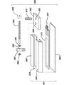
[0040] 図5は、図4に示すポテンショメータ構体50又は52の頂部平面図である。図6は、図5に示すポテンショメータ構体50又は52の側面立面図である。図7は、図6に示すポテンショメータ構体50又は52の左側立面図である。図8は、図5から図7に示すポテンショメータ構体50又は52の分解斜視図である。 [0040] FIG. 5 is a top plan view of the potentiometer assembly 50 or 52 shown in FIG. FIG. 6 is a side elevation view of the potentiometer assembly 50 or 52 shown in FIG. FIG. 7 is a left side elevational view of the potentiometer assembly 50 or 52 shown in FIG. FIG. 8 is an exploded perspective view of the potentiometer assembly 50 or 52 shown in FIGS.

[0041] 図5から図8に示すように、ポテンショメータ構体50/52は、リニアポテンショメータ72を包含する収容部70を有する。収容部70は、ポテンショメータ72に係合するような形状及び位置にあるポテンショメータポインタ、スタイラス、接点、又は「ワイパ」74を受け入れるように通常は適応される。リニアポテンショメータ72は、ポテンショメータ72から電気信号を受信し、ポテンショメータ72に沿ったポインタ74の位置決めに基づき電気信号を出力するように適応された、2つ以上の電気信号出力部、ピン、又は接点75、76、及び77を通常有する。例えば、一態様では、ピン75は、電力、例えば、DC電圧を受信してもよい。ピン76は「コレクタ」であってもよく、それからポテンショメータ72からの出力を得てもよい(例えば受信器210への入力については図10参照)。ピン77は、アースであってもよい。例えば一態様では、ポインタ74は、弾性を有する先端部、例えばスプリングで付勢した先端部を有するねじ付きロッドを備えてもよい。ポインタ74は導電性又は非導電性であってもよい。本発明の最も広範囲の態様によると、収容部70は、リニアポテンショメータ72を保持するように適応され、収容部70は、ポインタ74がリニアポテンショメータ72に接触し、一方でポインタ74の移動を可能にするように、ポインタ74を受け入れ及び位置決めるように適応される。一態様では、ポインタ又はワイパ74(及び本明細書中に開示されるあらゆる他のポインタ又はワイパ)は、例えば「迅速な」係合及び離脱のためといった、手動又は自動的に選択的に係合及び離脱するように、リニアポテンショメータ72と選択的に係合又は接触してもよい。例えば一態様では、ポインタ又はワイパ74は、例えばスプリングで付勢したピンを押すこと又はエラストマーで付勢したレバーをたわませることにより、ポテンショメータ72に係合及び離脱するように適応されたスプリング又はエラストマーで付勢したピン又はポイントを有してもよい。一態様では、ポインタ又はワイパ74とポテンショメータ72の係合及び離脱は、例えば作動されるとき、係止装置が例えば、手動で離脱するように離脱されるまで、ポインタ74をポテンショメータ72と係合及び係合を保持するように適応された、係止装置又はロック装置を有してもよい。本発明の態様によると、ポインタ74の移動とともに、ポテンショメータ72から出力部、又は接点75、76、及び/又は77への電気信号出力は変わる。本発明の一態様によると、収容部70に関するあらゆる形態の構造を、所望の機能及び結果に影響するよう使用してもよい。この点で有効と実証された収容部及びポテンショメータの1つの配置が、図5〜図8に示される。 [0041] As shown in FIGS. 5 to 8, the potentiometer assembly 50/52 includes an accommodating portion 70 that includes a linear potentiometer 72. The receptacle 70 is typically adapted to receive a potentiometer pointer, stylus, contact, or “wiper” 74 that is shaped and positioned to engage the potentiometer 72. The linear potentiometer 72 receives two electrical signals from the potentiometer 72 and is adapted to output an electrical signal based on the positioning of the pointer 74 along the potentiometer 72. Two or more electrical signal outputs, pins, or contacts 75 are adapted. , 76, and 77. For example, in one aspect, pin 75 may receive power, eg, a DC voltage. Pin 76 may be a “collector” and may then obtain the output from potentiometer 72 (see, eg, FIG. 10 for input to receiver 210). The pin 77 may be ground. For example, in one aspect, the pointer 74 may comprise a threaded rod having a resilient tip, such as a spring biased tip. The pointer 74 may be conductive or non-conductive. According to the broadest aspect of the present invention, the housing 70 is adapted to hold a linear potentiometer 72, which allows the pointer 74 to contact the linear potentiometer 72 while allowing the pointer 74 to move. As such, it is adapted to receive and position the pointer 74. In one aspect, the pointer or wiper 74 (and any other pointer or wiper disclosed herein) is selectively engaged manually or automatically, eg, for “rapid” engagement and disengagement. And may selectively engage or contact the linear potentiometer 72 to disengage. For example, in one aspect, the pointer or wiper 74 is a spring adapted to engage and disengage from the potentiometer 72, for example, by pushing a spring biased pin or deflecting an elastomer biased lever. It may have pins or points biased with elastomer. In one aspect, the engagement and disengagement of the pointer or wiper 74 and the potentiometer 72, for example when activated, engages and disengages the pointer 74 with the potentiometer 72 until the locking device is disengaged, for example, to be manually disengaged. There may be a locking or locking device adapted to retain the engagement. According to an aspect of the present invention, as the pointer 74 moves, the electrical signal output from the potentiometer 72 to the output or contacts 75, 76, and / or 77 changes. In accordance with one aspect of the present invention, any form of structure for the receptacle 70 may be used to affect the desired function and result. One arrangement of receptacles and potentiometers that have proven effective in this respect is shown in FIGS.

[0042] 図5〜図8に示すように、収容部70は、ポインタ74を受け入れるように適応されたスロット又は空洞78を備えてもよい。例えば示されるように、一態様では、収容部70は、ポインタ74を有するポインタホルダ82又は「スライダ」を受け入れる位置及びサイズの対向するチャネル80のセットを備えてもよい。ポインタ74を、従来の手段、例えば接着、機械的留め具、又は溶接によりポインタホルダ82内に位置決めてもよい。図8に示すように、ポインタ74は、1つ又は複数のねじ付き穴83、例えばポインタホルダ82内のねじ付き貫通穴に係合するねじ付きロッドを備えてもよい。別の態様では、ポインタ74を、例えば機械的留め具により、溶接によりポインタホルダ82にしっかりと取り付けてもよく、又は単一の一体式構成要素としてポインタホルダ82と一体的に形成してもよい。 [0042] As shown in FIGS. 5-8, the receptacle 70 may include a slot or cavity 78 adapted to receive a pointer 74. For example, as shown, in one aspect, the receptacle 70 may comprise a set of opposing channels 80 in position and size that receive a pointer holder 82 or “slider” having a pointer 74. The pointer 74 may be positioned in the pointer holder 82 by conventional means such as gluing, mechanical fasteners, or welding. As shown in FIG. 8, the pointer 74 may include a threaded rod that engages one or more threaded holes 83, such as threaded through holes in the pointer holder 82. In another aspect, the pointer 74 may be securely attached to the pointer holder 82 by welding, for example, by mechanical fasteners, or may be integrally formed with the pointer holder 82 as a single integral component. .

[0043] 本発明の一態様によると、ポインタ74を有するポインタホルダ82は、収容部70内、例えばチャネル80内で、図3及び図4のステージ42及び/又はスライドホルダ46の移動とともに移動するように適応される。従って、本発明の態様によると、ポインタホルダ82はステージ42に作動可能に接続され、及び/又は、スライドホルダ46及びポインタホルダ82は、ステージ42及び/又はスライドホルダ46の移動に応え移動してもよい。一態様では、ポインタホルダ82を、あらゆる従来の手段、例えばあらゆるタイプのハードウェア及び/又は留め具により、ステージ42及び/又はスライドホルダ46に作動可能に接続してもよい。図5〜図8に示す本発明の態様で、ポインタホルダ82は、結合具、例えば、1つ又は複数のロッド85を用いてステージ42及び/又はスライドホルダ46に作動可能に接続される。1つ又は複数のロッド85は、バー、ネジ無しロッド、ねじ付きロッド、又はチューブなどであってもよい。図8に示すように、一態様では、ロッド85は、ポインタホルダ82内のねじ付き穴81に係合するように適応された少なくとも1つのねじ付き端部87を有する少なくとも部分的にねじ付きされたロッドであってもよい。 [0043] According to one aspect of the present invention, the pointer holder 82 having the pointer 74 moves in the accommodating portion 70, for example, in the channel 80, with the movement of the stage 42 and / or the slide holder 46 in FIGS. To be adapted. Thus, according to aspects of the present invention, pointer holder 82 is operatively connected to stage 42 and / or slide holder 46 and pointer holder 82 move in response to movement of stage 42 and / or slide holder 46. Also good. In one aspect, pointer holder 82 may be operatively connected to stage 42 and / or slide holder 46 by any conventional means, such as any type of hardware and / or fasteners. 5-8, the pointer holder 82 is operably connected to the stage 42 and / or the slide holder 46 using a coupler, for example, one or more rods 85. The one or more rods 85 may be bars, unthreaded rods, threaded rods, tubes, or the like. As shown in FIG. 8, in one aspect, the rod 85 is at least partially threaded having at least one threaded end 87 adapted to engage a threaded hole 81 in the pointer holder 82. It may be a rod.

[0044] 図3及び図4に示すように、ポインタ51及び53からステージ42及び/又はスライドホルダ46の間の結合具は、1つ又は複数のロッド56又は58を備えてもよい。また、図3及び図4に示すように、ロッド56(図5では85)をスライドホルダ46に取り付けてもよく、ロッド58(85)を従来のハードウェア、例えば、図3にそれぞれ示す内部ねじ付きチューブ57及び59、を用いてステージ42に取り付けてもよい。内部ねじ付きチューブ57及び59を、接着、はんだ付け、溶接を含む従来の手段によって、又は、機械的留め具でステージ42に取り付けてもよい。
[0044] As shown in FIGS. 3 and 4, the coupler between the pointers 51 and 53 and the stage 42 and / or the slide holder 46 may comprise one or more rods 56 or 58. 3 and 4, the rod 56 (85 in FIG. 5) may be attached to the slide holder 46, and the rod 58 (85) may be attached to conventional hardware, for example, the internal screw shown in FIG. The attached tubes 57 and 59 may be used to attach to the stage 42. Internally threaded tubes 57 and 59 may be attached to stage 42 by conventional means including gluing, soldering, welding, or with mechanical fasteners.

[0045] また、図5〜図8に示すように、収容部70は、下部プレート又は「基部プレート」84を有してもよく、これに、例えば機械的留め具、接着、はんだ付け又は溶接によって、チャネル80を取り付けてもよい。本発明の一態様では、スロット78を形成するチャネル80を、基部プレート84と一体的に形成、例えば押し出し加工又は鋳造として形成してもよい。 [0045] Also, as shown in FIGS. 5-8, the receptacle 70 may have a lower plate or "base plate" 84, for example, mechanical fasteners, adhesion, soldering or welding. The channel 80 may be attached by In one aspect of the invention, the channel 80 forming the slot 78 may be formed integrally with the base plate 84, for example as an extrusion or casting.

[0046] 図5〜図8に示すように、ポテンショメータ72は、収容部70により受け入れられるよう適応され、及び、そのようなサイズの細長形の構造を備えてもよい。本発明の態様によると、ポテンショメータ72は、ポインタ74、又は同様の機能の装置の位置に基づき電気信号を出力するように適応されたあらゆる形態の直線状の電気構成要素又は装置であってもよい。一態様では、ポテンショメータ72は、「膜タイプ」のポテンショメータを備えてもよい。ポテンショメータ72が膜タイプのポテンショメータを備えるとき、ポインタ74を、ポテンショメータ72の膜をたわませ、それが導電性物質間の接触を起こし、膜タイプのポテンショメータ72の長さに沿ってポインタ74の位置に対応する又は関連する出力信号を生成するように適応してもよい。他のタイプの膜ポテンショメータを使用してもよいが、一態様では、ポテンショメータ72は、ユタ州Salt Lake CityのSpectra Symbolにより提供される膜タイプのポテンショメータを備える。例えば、ポテンショメータ72は、Spectra Symbolのデータシート「Diagrams and Schematics」に開示されたSpectra Symbolの「ThinPot」ポテンショメータを備えてもよく、「Diagrams and Schematics」は参照により本明細書に含まれる。 [0046] As shown in FIGS. 5-8, potentiometer 72 is adapted to be received by receptacle 70 and may comprise an elongated structure of such size. In accordance with aspects of the present invention, potentiometer 72 may be any form of linear electrical component or device adapted to output an electrical signal based on the position of pointer 74 or a device of similar function. . In one aspect, potentiometer 72 may comprise a “membrane type” potentiometer. When the potentiometer 72 comprises a membrane-type potentiometer, the pointer 74 deflects the membrane of the potentiometer 72, causing contact between the conductive materials, and the position of the pointer 74 along the length of the membrane-type potentiometer 72 May be adapted to generate an output signal corresponding to or associated with. In one aspect, potentiometer 72 comprises a membrane-type potentiometer provided by Spectra Symbol of Salt Lake City, Utah, although other types of membrane potentiometers may be used. For example, the potentiometer 72 may comprise a Spectra Symbol “Thin Pot” potentiometer disclosed in the Spectra Symbol data sheet “Diagrams and Schematics,” which is hereby incorporated by reference.

[0047] また、図5〜図8に示すように、ポテンショメータ構体50/52を、ポテンショメータ72を受け入れ及び使用するように適応してもよい。例えば一態様では、ポテンショメータ構体50/52は、ポテンショメータ72を受け入れるように適応及び位置決められた基板又はプレート86を有してもよい。例えば、ポテンショメータ72を例えば接着又は機械的留め具でプレート86に取り付けてもよく、プレート86は、収容部70の中又は上を、例えば図8の両方向の矢印88で示されるように移動してもよい。プレート86及びポテンショメータ72の移動又は摺動は、ポテンショメータ72の出力を変更又は調節、例えばその後の参照のため出力を標準に戻す又は「ゼロにする」機能をもたらしてもよい。一態様では、プレート86は、「スライドバー」とも呼ぶこともあるが、これを収容部70内又は上を摺動するように適応してもよく、例えば、プレート86は、摩擦を減少する素材、例えば、PTFE含有素材、例えば、DuPontのTEFLON(登録商標)PTFE又はSaint−GobainのRULON(登録商標)PTFE、又はそれらと同等のものを有してもよい。 [0047] Also, as shown in FIGS. 5-8, potentiometer assembly 50/52 may be adapted to receive and use potentiometer 72. For example, in one aspect, potentiometer assembly 50/52 may have a substrate or plate 86 adapted and positioned to receive potentiometer 72. For example, the potentiometer 72 may be attached to the plate 86 by, for example, an adhesive or mechanical fastener, and the plate 86 is moved in or on the receptacle 70 as shown, for example, by the bidirectional arrow 88 in FIG. Also good. Movement or sliding of the plate 86 and potentiometer 72 may provide a function to change or adjust the output of the potentiometer 72, eg, to return the output to standard or “zero” for subsequent reference. In one aspect, the plate 86 may also be referred to as a “slide bar”, but it may be adapted to slide in or on the receptacle 70, for example, the plate 86 may be a material that reduces friction. For example, it may have a PTFE-containing material such as DuPont's TEFLON® PTFE or Saint-Gobain's RULON® PTFE, or the like.

[0048] 図8で最も明らかに示すように、一態様では、収容部70を、プレート86の移動又は摺動を受け入れ及び/又は収容するように適応してもよい。例えば図8に示すように、収容部70は、プレート86の移動を受け入れ及び/又は誘導するチャネル90を備えてもよく、プレート86の上にポテンショメータ72が取り付けられる。一態様では、チャネル90を、誘導プレート又は「スペーサ片」92により形成してもよく、例えば、プレート92を基部プレート84に取り付け、プレート92はプレート86の移動を受け入れ及び誘導する位置及びサイズであってもよい。一態様では、プレート92を、接着により、機械的留め具、はんだ付けにより、又は溶接により基部プレート84に取り付けてもよい。本発明の一態様では、スペーサ片92を基部プレート84と一体的に形成してもよく、例えば基部プレート84内に機械加工、又は基部プレート84とともに押し出し加工又は鋳造として形成してもよい。一態様では、それぞれのスペーサ片92の幅は、それぞれのチャネル80の幅より狭くてもよい。図7で最も明らかに示すように、スペーサ片92の幅が、チャネル80の幅より狭いとき、幅の差がそれぞれのチャネル80の下部と、プレート86の少なくともいくぶんかの保持をもたらすそれぞれの基部プレート84の頂部の間に空洞91(例えば、一対の対向する空洞91)をもたらすことが可能である。例えば、それぞれのチャネル80の下部の少なくとも部分及びそれぞれの基部プレート84の頂部の少なくとも部分は、プレート86の垂直の保持を提供し得て、スペーサ片92の内部の縁部は、プレート86の横からの保持を提供し、一方でプレート86の長手方向の移動を可能にし得る。 [0048] As shown most clearly in FIG. 8, in one aspect, the receptacle 70 may be adapted to receive and / or accommodate movement or sliding of the plate 86. For example, as shown in FIG. 8, the receptacle 70 may include a channel 90 that accepts and / or guides movement of the plate 86, and a potentiometer 72 is mounted on the plate 86. In one aspect, the channel 90 may be formed by a guide plate or “spacer piece” 92, eg, attached to the base plate 84, where the plate 92 is in a position and size to accept and guide movement of the plate 86. There may be. In one aspect, the plate 92 may be attached to the base plate 84 by gluing, by mechanical fasteners, soldering, or by welding. In one aspect of the present invention, the spacer piece 92 may be formed integrally with the base plate 84, for example, machined in the base plate 84, or extruded or cast with the base plate 84. In one aspect, the width of each spacer piece 92 may be narrower than the width of each channel 80. As most clearly shown in FIG. 7, when the width of the spacer piece 92 is narrower than the width of the channel 80, the difference in width results in the bottom of each channel 80 and each base providing at least some retention of the plate 86. It is possible to provide a cavity 91 (eg, a pair of opposing cavities 91) between the tops of the plates 84. For example, at least in part and at least part of the top of each of the base plate 84 of the lower portion of each channel 80 is obtained by providing the holding of the vertical plate 86, the inside of the edge of the spacer piece 92, the horizontal plate 86 Can be provided, while allowing longitudinal movement of the plate 86.

[0049] また、図5〜図8に示すように、ポテンショメータ構体50/52をまた、プレート86及びプレート86に取り付けられたポテンショメータ72の位置を変更又は調節するように適応してもよい。例えば一態様では、ポテンショメータ構体50/52は、例えばその後の参照のため出力を標準に戻す又はゼロにするといった、ポテンショメータ72の出力を変更するように、プレート86及びポテンショメータ72の位置を変更するように適応された調整構体94を有してもよい。ポテンショメータ72の位置を調整する種々の手段、及び種々の調整機構を使用してもよいが、一態様では図8に示すように、調整構体94は、調整チューブ又はブロック96、ロッド取付チューブ、ブロック、又は「ロッドホルダ」98、調整ロッド100、及び調整ノブ102を有してもよい。示されるように、調整チューブ又はブロック96を、通常は取り付け、例えば接着、機械的留め具、はんだ付け、又は溶接などでプレート86に実質的にしっかりと取り付けてもよい。例えば調整チューブ96は、基部プレート84内のスロット又は開口部104を介してプレート86にアクセスしてもよい。調整チューブ又はブロック96は、穴97、例えば調整ロッド100上のねじ部に係合するように適応されたねじ付き穴を通常は有してもよい。ロッド取付チューブ又はブロック98を、通常は例えば接着、機械的留め具、はんだ付け、又は溶接などで実質的にしっかりと基部プレート84に取り付けてもよい。ロッド取付チューブ又はブロック98は、通常は穴99、例えば調整ロッド100を受け入れ及び支持するように適応された貫通穴を有してもよい。調整ロッド100は、例えば並目ねじ(UNC)又は細目ねじ(UNF)を有し、調整ブロック96内の相補するねじ付き穴97にネジ止めにより係合する金属ねじ付きロッドを備えてもよい。調整ノブ102は、操作及び回転、例えば調整ロッド100の快適な回転を容易にするあらゆる構造であってもよい。 [0049] Also, as shown in FIGS. 5-8, the potentiometer assembly 50/52 may also be adapted to change or adjust the position of the plate 86 and the potentiometer 72 attached to the plate 86. For example, in one aspect, the potentiometer assembly 50/52 may change the position of the plate 86 and the potentiometer 72 to change the output of the potentiometer 72, eg, to return the output to standard or zero for subsequent reference. An adjustment structure 94 adapted to the above may be provided. Various means for adjusting the position of the potentiometer 72 and various adjustment mechanisms may be used, but in one aspect, as shown in FIG. 8, the adjustment assembly 94 comprises an adjustment tube or block 96, a rod mounting tube, a block. , Or “rod holder” 98, adjustment rod 100, and adjustment knob 102. As shown, the adjustment tube or block 96 may be attached substantially securely to the plate 86, typically by attachment, such as gluing, mechanical fasteners, soldering, or welding. For example, the adjustment tube 96 may access the plate 86 through a slot or opening 104 in the base plate 84. The adjustment tube or block 96 may typically have a threaded hole adapted to engage a hole 97, eg, a thread on the adjustment rod 100. The rod mounting tube or block 98 may be attached to the base plate 84 substantially securely, typically by gluing, mechanical fasteners, soldering, or welding, for example. The rod mounting tube or block 98 may have a through hole that is usually adapted to receive and support the hole 99, eg, the adjustment rod 100. The adjustment rod 100 may comprise, for example, a coarse thread (UNC) or fine thread (UNF) and may comprise a metal threaded rod that engages with a complementary threaded hole 97 in the adjustment block 96 by screwing. The adjustment knob 102 may be any structure that facilitates operation and rotation, eg, comfortable rotation of the adjustment rod 100.

[0050] 一態様では、図8に示すように、調整ノブ102は、例えば操作者の操作を容易にするように適応された刻み付き外径又は表面を有する金属又はプラスチックの円盤又はプレートであってもよい。別の態様では、調整ノブ102は、調整ロッド100に取り付けられたレバーアームを備えてもよい。レバーアームのたわみ、例えば、自動又は手動のたわみが調整ロッド100を回転して所望に応じてポテンショメータ72を移動してもよい。調整ロッド100の回転を、手動に加え自動で生じさせてもよいこともまた想定される。例えば調整ロッド100を、回転アクチュエータ、例えば、ステッパモータに作動可能に接続された電子コントローラ(図示せず)へのユーザ入力といったユーザ入力に応えロッド100を回転するように適応されたステッパモータに作動可能に接続してもよい。 [0050] In one aspect, as shown in FIG. 8, the adjustment knob 102 is, for example, a metal or plastic disk or plate having a knurled outer diameter or surface adapted to facilitate operator operation. May be. In another aspect, the adjustment knob 102 may comprise a lever arm attached to the adjustment rod 100. Lever arm deflection, for example, automatic or manual deflection, may rotate adjustment rod 100 to move potentiometer 72 as desired. It is also envisioned that rotation of the adjustment rod 100 may occur automatically in addition to manual operation. For example, adjusting rod 100 is actuated on a rotary actuator, eg, a stepper motor adapted to rotate rod 100 in response to user input, such as user input to an electronic controller (not shown) operably connected to a stepper motor. You may connect as possible.

[0051] プレート86とポテンショメータ72との移動を、プレート86に作動可能に接続されたリニアアクチュエータを用いて実行してもよいこともまた想定される。例えば一態様では、リニア位置決めトランスデューサのような空圧式アクチュエータ、液圧式アクチュエータ、機械的アクチュエータ、又は電気アクチュエータを、調整構体94の代わりに又は加えて使用してもよい。さらに、1つ又は複数のこれらのトランスデューサが、例えばトランスデューサに作動可能に接続された電子コントローラ(図示せず)へのユーザ入力といったユーザ入力に応えて、プレート86を移動してもよいことが想定されている。 [0051] It is also envisioned that movement of plate 86 and potentiometer 72 may be performed using a linear actuator operably connected to plate 86. For example, in one aspect, pneumatic actuators, hydraulic actuators, mechanical actuators, or electrical actuators such as linear positioning transducers may be used in place of or in addition to adjustment assembly 94. Further, it is envisioned that one or more of these transducers may move plate 86 in response to user input, eg, user input to an electronic controller (not shown) operably connected to the transducer. Has been.

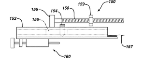
[0052] 図9は、本発明の態様による図6に類似の他のポテンショメータ構体150の側面図である。ポテンショメータ構体150は、図5〜図8に示す構体50/52と非常に類似していてもよい。電位差測定構体150は、(例えば収容部70と同様の)収容部152、(例えばポインタ74と同様の)ポインタ154、(例えばポインタホルダ82と同様の)ポインタホルダ156、(例えば結合具85と同様の)結合具158、出力部157を有するリニアポテンショメータ(図示せず、例えばリニアポテンショメータ72と同様)、及び(例えば調整構体94と同様の)調整構体160を有してもよい。図9に示す態様によると、図5〜図8に示す態様と異なり、ポテンショメータ構体150の結合具158の1つの端部は、ステージ42及び/又はスライドホルダ46(図3及び図4参照)に作動可能に接続され、結合具158の他の端部は、ピン155に係合し、すなわちポインタホルダ156に係合する代わりである。図9に示す態様で、ピン155は、ポインタホルダ156に取り付け及び/又は装着され、例えばポインタホルダ156内にねじ込まれる。この態様によると、例えば1つ又は複数のロッドといった結合具158は、従来の手段、例えば機械的留め具でピン155に係合してもよい。一態様では、結合具158をピン155に回転可能に取り付けてもよく、結合具158は結合具158の中心線の周囲を回転し、一方でピン155で係合されてもよい。本発明のこの態様によると、(例えば結合具158にしっかりと取り付けられたナット159の回転により誘発された)結合具158の移動はまた、ポインタホルダ156、及びポインタホルダ156内に取り付けられたポインタ154も移動する。一態様では、調整構体160の代わりに又は併せて、ポテンショメータ構体150は結合具158を備える調整機構を有してもよい。一態様では、結合具158は、例えばねじ付き留め具によってスライドホルダ46又はステージ42(図示せず)にネジ止めにより係合し得るねじ付きロッドであってもよい。この態様によると、例えばロッド158に固定されたナット159、又はロッド158に固定された同様の構造によるねじ付きロッド158の回転は、ポインタ154をリニアポテンショメータに沿って移動して、とりわけポインタ154の位置を変え、よってポテンショメータの出力を変え、例えばポテンショメータの出力を標準に戻す又は「ゼロにする」。図9では示されないが、調整機構構体160を省いた状態で、調整機構160に関連する構造、例えば、図8に示すプレート86、スペーサ片92、及び/又はスロット104を省いてもよいことが想定されている。例えば、図8に示す配置に示唆されるように、ポテンショメータ72を基部プレート84に直接取り付けてもよい。 [0052] FIG. 9 is a side view of another potentiometer assembly 150 similar to FIG. 6 in accordance with aspects of the present invention. The potentiometer assembly 150 may be very similar to the assembly 50/52 shown in FIGS. The potentiometric structure 150 includes an accommodating part 152 (for example, similar to the accommodating part 70), a pointer 154 (for example similar to the pointer 74), a pointer holder 156 (for example similar to the pointer holder 82), and (for example, similar to the coupler 85). A linear potentiometer (not shown, for example, similar to the linear potentiometer 72), and an adjustment structure 160 (for example, similar to the adjustment structure 94). According to the embodiment shown in FIG. 9, unlike the embodiments shown in FIGS. 5 to 8, one end of the coupler 158 of the potentiometer assembly 150 is attached to the stage 42 and / or the slide holder 46 (see FIGS. 3 and 4). Operatively connected, the other end of the coupler 158 engages the pin 155, ie, instead of engaging the pointer holder 156. In the embodiment shown in FIG. 9, the pin 155 is attached and / or attached to the pointer holder 156 and is screwed into the pointer holder 156, for example. According to this aspect, the coupler 158, eg, one or more rods, may engage the pin 155 with conventional means, such as a mechanical fastener. In one aspect, the coupler 158 may be rotatably attached to the pin 155, and the coupler 158 may rotate around the centerline of the coupler 158 while being engaged with the pin 155. According to this aspect of the invention, movement of coupler 158 (e.g., induced by rotation of nut 159 secured to coupler 158) also includes pointer holder 156 and pointer mounted within pointer holder 156. 154 also moves. In one aspect, the potentiometer assembly 150 may have an adjustment mechanism with a coupler 158 instead of or in conjunction with the adjustment assembly 160. In one aspect, the coupler 158 may be a threaded rod that may be threadedly engaged with the slide holder 46 or the stage 42 (not shown), for example by a threaded fastener. According to this aspect, rotation of a threaded rod 158, such as a nut 159 secured to the rod 158, or a similar structure secured to the rod 158, moves the pointer 154 along the linear potentiometer, and in particular the pointer 154 Change the position, thus changing the output of the potentiometer, eg, returning the potentiometer output to standard or “zeroing”. Although not shown in FIG. 9, the structure related to the adjustment mechanism 160, for example, the plate 86, the spacer piece 92, and / or the slot 104 shown in FIG. Assumed. For example, the potentiometer 72 may be attached directly to the base plate 84, as suggested by the arrangement shown in FIG.

[0053] 図9Aは、図3に示すポテンショメータ構体50及び/又は52の代わりに使用し得る別のポテンショメータ構体350の側面図である。図9Bは、図9Aに示す別のポテンショメータ構体の分解斜視図である。示されるように、ポテンショメータ構体350は、例えば図5〜図8に関して示され及び記載されたポテンショメータ72と実質的に同一のポテンショメータといった、リニアポテンショメータ372(図9B参照)を包含する収容部370を有する。収容部370は、本明細書中に開示された収容部70と同様であってもよく、ポテンショメータ372に係合するような形状及び位置にあるポテンショメータポインタ、スタイラス、接点、又は「ワイパ」374を受け入れるように通常は適応される。本明細書に記載されたように、ポインタ374は、弾性を有する先端部、例えば、スプリングで付勢した先端部を有するねじ付きロッドを備えてもよい。本明細書に記載されたように、リニアポテンショメータ372は、1つ又は複数の電気信号出力部又は接点357を通常有し、それらは、ポテンショメータ372から電気信号を受信し、ポテンショメータ372に沿ったポインタ374の位置決めに基づき電気信号を出力するように適応される。本発明の最も広範囲の態様によると、収容部370はリニアポテンショメータ372を保持するように適応され、収容部370は、ポインタ374がリニアポテンショメータ372と接触し、一方でポインタ374の移動を可能にするように、ポインタ374を受け入れ及び位置決めるように適応される。 [0053] FIG. 9A is a side view of another potentiometer assembly 350 that may be used in place of the potentiometer assembly 50 and / or 52 shown in FIG. FIG. 9B is an exploded perspective view of another potentiometer structure shown in FIG. 9A. As shown, the potentiometer assembly 350 includes a housing 370 that includes a linear potentiometer 372 (see FIG. 9B), such as a potentiometer substantially the same as the potentiometer 72 shown and described with respect to FIGS. . The receptacle 370 may be similar to the receptacle 70 disclosed herein and includes a potentiometer pointer, stylus, contact, or “wiper” 374 in a shape and position that engages the potentiometer 372. Usually adapted to accept. As described herein, the pointer 374 may comprise a threaded rod having a resilient tip, such as a spring biased tip. As described herein, the linear potentiometer 372 typically has one or more electrical signal outputs or contacts 357 that receive electrical signals from the potentiometer 372 and pointers along the potentiometer 372. Based on the positioning of 374, it is adapted to output an electrical signal. According to the broadest aspect of the present invention, the receiving portion 370 is adapted to hold a linear potentiometer 372, which allows the pointer 374 to contact the linear potentiometer 372 while allowing the pointer 374 to move. As such, the pointer 374 is adapted to be received and positioned.

[0054] 図9Bに示すように、収容部370は、ポインタ374を受け入れるように適応されたスロット又は空洞378を備えてもよい。例えば示されるように、一態様では、収容部370は、ポインタ374を担持するポインタホルダ又は「スライダ」382を受け入れる位置及びサイズの対向するチャネルのセット380を備えてもよい。ポインタ374を、従来の手段、例えば接着、機械的留め具、又は溶接によりポインタホルダ382内に位置決めてもよい。図9Bに示すように、ポインタ374は、1つ又は複数のねじ付き穴383、例えばポインタホルダ382内のねじ付き貫通穴に係合するねじ付きロッドを備えてもよい。 [0054] As shown in FIG. 9B, the receptacle 370 may include a slot or cavity 378 adapted to receive the pointer 374. For example, as shown, in one aspect, the receptacle 370 may include a set 380 of opposed channels sized and positioned to receive a pointer holder or “slider” 382 that carries a pointer 374. The pointer 374 may be positioned in the pointer holder 382 by conventional means such as gluing, mechanical fasteners, or welding. As shown in FIG. 9B, the pointer 374 may comprise a threaded rod that engages one or more threaded holes 383, eg, threaded through holes in the pointer holder 382.

[0055] 本発明の一態様によると、ポインタ374を有するポインタホルダ382は、収容部370内、例えばチャネル380内で、図3及び図4に示すステージ42及び/又はスライドホルダ46の移動とともに移動するように適応される。従って本発明の態様によると、ポインタホルダ382及びポインタ374はステージ42及び/又はスライドホルダ46に作動可能に接続され、ポインタホルダ382及びポインタ374は、ステージ42及び/又はスライドホルダ46の移動に応え移動してもよい。一態様では、ポインタホルダ382を、あらゆる従来の手段、例えばあらゆるタイプのハードウェア及び/又は留め具により、ステージ42及び/又はスライドホルダ46に作動可能に接続してもよい。図9A及び図9Bに示す本発明の態様で、ポインタホルダ382は、結合具、例えば、ステージ42及び/又はスライドホルダ46に作動可能に接続された1つ又は複数のロッド385を用いて、ステージ42及び/又はスライドホルダ46に作動可能に接続される。1つ又は複数のロッド385は、ポインタホルダ382に取り付けられたピン387を係合してもよい。ピン387を、少なくとも部分的にねじ付き、及びポインタホルダ382内の1つ又は複数のねじ付き穴389にネジ止めにより係合するように適応してもよい。別の態様では、ピン387を例えば機械的留め具により、溶接により、ポインタホルダ382にしっかりと取り付けてもよく、又は単一の一体式構成要素としてポインタホルダ382と一体的に形成してもよい。1つ又は複数のロッド385は、バー、ねじ付き無しロッド、ねじ付きロッド、又はチューブなどであってもよい。図9A及び図9Bに示すように、一態様では、ロッド385はピン387に係合してもよく、ロッド385はピン387内の貫通穴390により受け入れられ、及び従来の手段により貫通穴390内で保持されてもよい。例えば一態様では、示されるように、ロッド385を一対の保持リング又はワッシャ392によりピン387の貫通穴390内に保持してもよい。例えば、リング392はそれぞれ、当業界で公知の他のタイプの従来の留め具の中でも、保持ワッシャ、保持リング、又はプッシュナットであってもよい。例えば、リング392はそれぞれ、例えばロッド385を係合する内部の突起を有する金属保持ワッシャ、保持リング、又はプッシュナットであってもよい。一態様では、ロッド385をピン387に回転可能に係合し、例えばロッド385は貫通穴390内で回転することが可能である。 [0055] According to one aspect of the present invention, the pointer holder 382 having the pointer 374 moves in the accommodating portion 370, for example, in the channel 380, with the movement of the stage 42 and / or the slide holder 46 shown in FIGS. Adapted to be. Thus, according to aspects of the present invention, pointer holder 382 and pointer 374 are operatively connected to stage 42 and / or slide holder 46, and pointer holder 382 and pointer 374 are responsive to movement of stage 42 and / or slide holder 46. You may move. In one aspect, the pointer holder 382 may be operatively connected to the stage 42 and / or the slide holder 46 by any conventional means, such as any type of hardware and / or fasteners. In the aspect of the present invention shown in FIGS. 9A and 9B, the pointer holder 382 uses a coupling, eg, one or more rods 385 operably connected to the stage 42 and / or the slide holder 46 to provide a stage. 42 and / or slide holder 46 is operably connected. One or more rods 385 may engage a pin 387 attached to the pointer holder 382. The pin 387 may be at least partially threaded and adapted to threadably engage one or more threaded holes 389 in the pointer holder 382. In another aspect, the pin 387 may be securely attached to the pointer holder 382, for example, by mechanical fasteners, by welding, or may be integrally formed with the pointer holder 382 as a single integral component. . The one or more rods 385 may be bars, unthreaded rods, threaded rods, tubes, or the like. As shown in FIGS. 9A and 9B, in one aspect, the rod 385 may engage a pin 387, which is received by the through hole 390 in the pin 387 and within the through hole 390 by conventional means. It may be held at. For example, in one aspect, as shown, the rod 385 may be retained within the through-hole 390 of the pin 387 by a pair of retaining rings or washers 392. For example, each ring 392 may be a retaining washer, retaining ring, or push nut, among other types of conventional fasteners known in the art. For example, each ring 392 may be, for example, a metal retaining washer, retaining ring, or push nut with an internal protrusion that engages rod 385. In one aspect, the rod 385 is rotatably engaged with the pin 387, for example, the rod 385 can rotate within the through hole 390.

[0056] 前述の図3及び図4に示すように、(図9A及び図9Bの)ポテンショメータ構体350内のポインタ374とステージ42及び/又はスライドホルダ46との間の結合具は、1つ又は複数のロッド56又は58を有してもよい。また図3及び図4に示すように、(図9A及び図9Bのロッド385に対応し得る)ロッド56及び58を、従来のハードウェア、例えば図3に示された内部ねじ付きチューブ57及び59のそれぞれを用いてスライドホルダ46及び/又はステージ42に取り付けてもよい。 [0056] As shown in FIGS. 3 and 4 above, there may be one coupling between the pointer 374 in the potentiometer assembly 350 (of FIGS. 9A and 9B) and the stage 42 and / or slide holder 46, or A plurality of rods 56 or 58 may be provided. Also as shown in FIGS. 3 and 4, rods 56 and 58 (which may correspond to rod 385 of FIGS. 9A and 9B) are connected to conventional hardware, such as the internally threaded tubes 57 and 59 shown in FIG. May be attached to the slide holder 46 and / or the stage 42.

[0057] また図9A及び図9Bに示すように、収容部370は、下部プレート又は「基部プレート」384を有してもよく、これに例えば機械的留め具、接着、はんだ付け、ろう付け又は溶接によってチャネル380を取り付けてもよい。本発明の一態様では、スロット378を形成するチャネル380を、基部プレート384と一体的に形成、例えば押し出し加工又は鋳造として形成してもよい。 [0057] Also as shown in FIGS. 9A and 9B, the receiving portion 370 may have a lower plate or “base plate” 384 to which, for example, mechanical fasteners, adhesion, soldering, brazing or The channel 380 may be attached by welding. In one aspect of the invention, the channel 380 forming the slot 378 may be formed integrally with the base plate 384, for example as an extrusion or casting.

[0058] 図9A及び図9Bに示すように、ポテンショメータ372は、収容部370により受け入れられるように適応され及びそのようなサイズの本明細書中に開示されるような細長形の構造を備えてもよく、ポインタ374、又は本明細書中に開示される同様の機能の装置の位置に基づき電気信号を出力するように適応されたあらゆる形態の直線状電気構成要素又は装置であってもよい。例えばポテンショメータ372は、本明細書中に開示されるSpectra Symbolにより提供される膜タイプポテンショメータのような「膜タイプ」ポテンショメータであってもよい。 [0058] As shown in FIGS. 9A and 9B, potentiometer 372 is adapted to be received by receptacle 370 and comprises an elongate structure of that size as disclosed herein. It may also be any form of linear electrical component or device adapted to output an electrical signal based on the position of the pointer 374 or a similarly functional device disclosed herein. For example, potentiometer 372 may be a “membrane type” potentiometer, such as the membrane type potentiometer provided by Spectra Symbol disclosed herein.

[0059] また図9A及び図9Bに示すように、ポテンショメータ構体350もまた、ポテンショメータ構体350内のポインタ374の位置を変更又は調節するように適応してもよい。例えば一態様では、ポテンショメータ構体350を、例えばステージ42及び/又はスライドホルダ46(図3参照)に関連してポインタ374の位置を変えるように適応してもよい。例えば一態様では、ポテンショメータ構体350は、ロッド385に取り付けられた(図9A及び図9Bの仮想線で示された)調整レバー又はナット395を有してもよく、ロッド385はレバー又はナット395の回転とともに回転する。レバー又はナット395を、従来の手段、例えば接着、はんだ付け、ろう付け又は溶接でロッド385にしっかりと取り付けてもよい。一態様では、ロッド385とレバー又はナット395の回転を、ステージ42及び/又はスライドホルダ46に対するポテンショメータ372に沿ったポインタ374の相対的な位置の変更に用いてもよい。例えば、ロッド385とステージ42及び/又はスライドホルダ46に取り付けられた(図3に示された内部ねじ付きチューブ57及び59のような)ねじ付き留め具のねじ付き係合により、レバー又はナット395の回転は、ステージ42及び/又はスライドホルダ46に対してポインタ374の位置を移動し得る。一態様では、レバー又はナット395の回転を、ポテンショメータ72の出力を変更し、例えばその後の参照のため出力を標準に戻す又は「ゼロにする」のに使用してもよい。 [0059] Also, as shown in FIGS. 9A and 9B, potentiometer assembly 350 may also be adapted to change or adjust the position of pointer 374 within potentiometer assembly 350. For example, in one aspect, potentiometer assembly 350 may be adapted to change the position of pointer 374 relative to, for example, stage 42 and / or slide holder 46 (see FIG. 3). For example, in one aspect, potentiometer assembly 350 may have an adjustment lever or nut 395 (shown in phantom lines in FIGS. 9A and 9B) attached to rod 385, and rod 385 may include a lever or nut 395. Rotates with rotation. The lever or nut 395 may be securely attached to the rod 385 by conventional means such as gluing, soldering, brazing or welding. In one aspect, rotation of rod 385 and lever or nut 395 may be used to change the relative position of pointer 374 along potentiometer 372 relative to stage 42 and / or slide holder 46. For example, lever or nut 395 by threaded engagement of a rod 385 and a threaded fastener (such as internally threaded tubes 57 and 59 shown in FIG. 3) attached to stage 42 and / or slide holder 46. Can move the position of the pointer 374 relative to the stage 42 and / or the slide holder 46. In one aspect, rotation of the lever or nut 395 may be used to change the output of the potentiometer 72, eg, to return the output to standard or “zero” for subsequent reference.

[0060] 一態様では、調整レバー又はナット395は、例えば操作者の操作を容易にするように適応された刻み付き外径又は表面を有する、金属又はプラスチックの円盤又はプレートであってもよい。別の態様では、ナット395は、ロッド385に取り付けられたレバーアームを備えてもよい。レバーアームのたわみ、例えば、自動又は手動のたわみがロッド385を回転して所望に応じてポインタ374を移動してもよい。レバー又はナット395の回転を、手動に加え自動で生じさせてもよいこともまた想定される。例えば、レバー又はナット395を、回転アクチュエータ、例えば、ステッパモータ(図示せず)に作動可能に接続された電子コントローラ(図示せず)へのユーザ入力といったユーザ入力に応えレバー又はナット395を回転するように適応されたステッパモータに作動可能に接続してもよい。 [0060] In one aspect, the adjustment lever or nut 395 may be a metal or plastic disk or plate, for example, having a knurled outer diameter or surface adapted to facilitate operator manipulation. In another aspect, the nut 395 may comprise a lever arm attached to the rod 385. Deflection of the lever arm, for example, automatic or manual deflection, may rotate the rod 385 to move the pointer 374 as desired. It is also envisioned that rotation of the lever or nut 395 may occur automatically in addition to manual operation. For example, the lever or nut 395 rotates the lever or nut 395 in response to a user input, such as a user input to a rotary actuator, eg, an electronic controller (not shown) operably connected to a stepper motor (not shown). It may be operably connected to an adapted stepper motor.

[0061] 図10は、本発明の態様を有するシステム200の概略図である。示されるように、システム200は、(図3に示すような)スライドホルダ46を有する顕微鏡ステージ42、(図3から図9Bに示すような)ポテンショメータ構体50及び52、並びに、ポテンショメータ構体50及び52に電気的に接続された受信器及び/又はディスプレイ210を通常有する。 [0061] FIG. 10 is a schematic diagram of a system 200 having aspects of the present invention. As shown, the system 200 includes a microscope stage 42 having a slide holder 46 (as shown in FIG. 3), potentiometer structures 50 and 52 (as shown in FIGS. 3-9B), and potentiometer structures 50 and 52. It typically has a receiver and / or display 210 electrically connected to the.

[0062] 示されるように、本明細書中に開示されるようなステージ42及び/又はスライドホルダ46の移動、及びポテンショメータ構体50及び52内のポインタの対応するふれとともに、ポテンショメータ構体50及び52内のポテンショメータは、図10の電気接続202及び204を介して電気信号を出力する。例えば、電気接続202及び204を、図6及び図8に示す接点75、76、及び77のうち1つ又は複数に電気的に接続してもよい。一態様では、接続202及び204は、例えば図6及び図8に示す接点75、76、及び77のうち少なくとも1つからの有線又は無線接続であってもよい。接続202及び204は、複数の接続又はケーブルを有してもよく、これらの接続の1つが受信器210からポテンショメータ構体50及び52へ、電力を送信し、例えばポテンショメータ72に電力を供給してもよい。本発明の一態様によると、接続202及び204により送信された信号は、受信器210により受信され、及び所望に応じて操作、表示、印刷及び/又は出力される。 [0062] As shown, in the potentiometer assemblies 50 and 52, along with the movement of the stage 42 and / or slide holder 46 as disclosed herein, and the corresponding deflection of the pointers in the potentiometer assemblies 50 and 52. The potentiometer outputs an electrical signal via the electrical connections 202 and 204 of FIG. For example, the electrical connections 202 and 204 may be electrically connected to one or more of the contacts 75, 76, and 77 shown in FIGS. In one aspect, connections 202 and 204 may be wired or wireless connections from at least one of contacts 75, 76, and 77 shown in FIGS. 6 and 8, for example. Connections 202 and 204 may have multiple connections or cables, one of which may transmit power from receiver 210 to potentiometer assemblies 50 and 52, for example, to provide power to potentiometer 72. Good. In accordance with one aspect of the present invention, signals transmitted over connections 202 and 204 are received by receiver 210 and manipulated, displayed, printed and / or output as desired.

[0063] 受信器210は、収容部212及び種々の信号入力、操作、記憶及び/又は出力装置を有する。例えば受信器210は、例えば数字を表示するように適応されたデジタルディスプレイといった1つ又は複数のディスプレイ214及び216、及び電源スイッチ218を有してもよい。受信器210は、1つ又は複数のスイッチ又はボタンなど、例えば本明細書中に開示されるように、例えばステージ42上のスライド43の方向に応えて、ポテンショメータ72による検出された位置の出力の表示される極性を変更するように適応されたトグルスイッチといった、1つ又は複数のトグルスイッチ211を有してもよい。本発明の他の態様で、ディスプレイ214及び216は、例えば接続202及び204を介して受信された電気信号に関連する画像を表示するように適応されたグラフィックディスプレイであってもよい。例えば、接続202及び204から受信された信号がポテンショメータ構体50及び52内のポテンショメータ上のポインタの位置に関連付けられる一態様では、受信器210を、測定単位無しで、又は例えばインチ(in.)又はミリメートル(mm)といった測定単位で、ディスプレイ214及び216上に、例えば数字、アルファベット、又は英数字で位置を表示するように適応してもよい。受信器210は、通常は電気接続215により電力を受信してもよく、接続217を介して出力信号を、例えば外部装置220へ、例えば、ディスプレイ、プリンタ、記憶装置、又は(無線信号を送信するように適応された送信器のような)送信器へ送信してもよい。一態様では、外部装置220は、信号を送信及び/又はインターネットのようなネットワークから受信するように適応されたルータ又はサーバであってもよい。受信器210はまた、例えばとりわけスライドホルダ上のスライドの方向又はディスプレイ214及び/又は216上に表示されたデータの極性をユーザに通知するよう、1つ又は複数の標識又は点灯部213を有してもよい。(図12及び図13の説明を参照されたい。) [0063] The receiver 210 includes a housing 212 and various signal input, manipulation, storage and / or output devices. For example, the receiver 210 may have one or more displays 214 and 216, such as a digital display adapted to display numbers, and a power switch 218, for example. The receiver 210 outputs one or more switches or buttons, such as disclosed herein, for example, in response to the direction of the slide 43 on the stage 42, of the detected position output by the potentiometer 72. There may be one or more toggle switches 211, such as a toggle switch adapted to change the displayed polarity. In other aspects of the invention, displays 214 and 216 may be graphic displays adapted to display images associated with electrical signals received via connections 202 and 204, for example. For example, in one aspect where the signals received from connections 202 and 204 are associated with the position of a pointer on the potentiometer in potentiometer structures 50 and 52, receiver 210 can be configured without a unit of measurement or, for example, in inches (in.) Or It may be adapted to display the position on the displays 214 and 216, for example in numbers, alphabets or alphanumeric characters, in units of measurement such as millimeters (mm). The receiver 210 may typically receive power via an electrical connection 215 and send an output signal via the connection 217, eg, to an external device 220, eg, a display, printer, storage device, or (wireless signal). May be transmitted to a transmitter (such as a transmitter adapted to In one aspect, the external device 220 may be a router or server adapted to transmit and / or receive signals from a network such as the Internet. The receiver 210 also has one or more indicators or lights 213 to inform the user of, for example, the direction of the slide on the slide holder or the polarity of the data displayed on the displays 214 and / or 216, among others. May be. (See the description of FIGS. 12 and 13)

[0064] 図11は、本発明の一態様による図10に示す受信器210の内容の1つのセットの概略平面図である。図11に示すように、受信器210は、接続202及び204を介して信号を受信するように適応された入力モジュール222、ディスプレイ214及び216、電力接続215に接続された電源装置224、及び図10に関して前述したように接続217を介して信号を送信するように適応された1つ又は複数の出力モジュール226を有してもよい。一態様では、入力モジュール222は、リレー、例えば、6−VDC、4極、双投リレーであってもよく、例えばIDEC Corporationが提供するリレー又はそれの同等物であってもよい。図11に示されたように、受信器210はまた構成要素の中で特に、1つ又は複数のプロセッサ228及び/又は1つ又は複数の記憶装置230を有してもよく、それらは入力モジュール222及び/又は出力モジュール226に作動可能に接続又は電気的に接続されてもよい。受信器210内で見られ得る他の電気構成要素は、当業者に明らかである。 [0064] FIG. 11 is a schematic plan view of one set of contents of the receiver 210 shown in FIG. 10 in accordance with an aspect of the present invention. As shown in FIG. 11, receiver 210 includes an input module 222 adapted to receive signals via connections 202 and 204, displays 214 and 216, power supply 224 connected to power connection 215, and FIG. There may be one or more output modules 226 adapted to transmit signals over connection 217 as described above for 10. In one aspect, the input module 222 may be a relay, such as a 6-VDC, 4-pole, double throw relay, such as a relay provided by IDEC Corporation, or the like. As shown in FIG. 11, the receiver 210 may also include, among other components, one or more processors 228 and / or one or more storage devices 230, which are input modules. 222 and / or output module 226 may be operatively connected or electrically connected. Other electrical components that may be found within receiver 210 will be apparent to those skilled in the art.

[0065] 図3〜図11に示す本発明の態様に関連して、本発明の一態様によると、顕微鏡10の視野内にスライド43上の対象を位置付け又は再捕捉する機器41が提供される。機器41は、1つ又は複数のポテンショメータ構体50及び52を有する。それぞれのポテンショメータ構体50及び52は、収容部70、収容部70内に位置し、ケーブル75、76、及び/又は77を介して信号を出力するように適応されたリニアポテンショメータ72、収容部70内に摺動可能に取り付けられ、接触、例えばリニアポテンショメータ72に選択的に接触するように適応された接点又は「ポインタ」74であって、リニアポテンショメータ72上のポインタ74の位置がリニアポテンショメータ72により出力される信号を決定する接点又は「ポインタ」74、及びポインタ74に作動可能に接続された第1端部、及び移動可能なステージ42又はステージ42に取り付けられた移動可能なスライドホルダ46に作動可能に接続された第2端部を有する結合具85を有する。本発明の態様によると、対象を有するスライド43又は移動可能なステージ42、又は両方を保持する移動可能なスライドホルダ46は、第1方向に移動可能である。機器は、リニアポテンショメータ72により出力された信号を受信し、信号を用いて顕微鏡10のステージ42上の移動可能な標本ホルダ46の位置を判断するように適応された受信器210(図10参照)を有してもよい。一態様では、判断された位置を、ディスプレイ214又は216、例えば受信器210内に位置するディスプレイに表示、そうでなければ格納及び/又は記録、例えば記載してもよい。 [0065] In connection with the aspects of the invention shown in FIGS. 3-11, according to one aspect of the invention, an instrument 41 is provided for positioning or recapturing an object on a slide 43 within the field of view of the microscope 10. . The device 41 has one or more potentiometer structures 50 and 52. The respective potentiometer structures 50 and 52 are located in the accommodating part 70, the accommodating part 70, and in the linear potentiometer 72 and the accommodating part 70, which are adapted to output signals via the cables 75, 76, and / or 77. A contact or “pointer” 74 that is slidably attached to the contact and adapted to selectively contact the linear potentiometer 72, for example, and the position of the pointer 74 on the linear potentiometer 72 is output by the linear potentiometer 72. Operable on a contact or “pointer” 74 that determines the signal to be transmitted, and a first end operably connected to the pointer 74, and a movable stage 42 or a movable slide holder 46 attached to the stage 42 And a coupler 85 having a second end connected thereto. According to an aspect of the present invention, the movable slide holder 46 that holds the target slide 43 or the movable stage 42, or both, is movable in the first direction. The instrument receives the signal output by the linear potentiometer 72 and uses the signal to determine the position of the movable specimen holder 46 on the stage 42 of the microscope 10 (see FIG. 10). You may have. In one aspect, the determined position may be displayed on display 214 or 216, eg, a display located within receiver 210, otherwise stored and / or recorded, eg, described.

[0066] 本発明の一態様では、ポテンショメータ72を、例えば受信器210から接続202又は204を介してポテンショメータ72へ設けられたケーブルにより、例えば約5ボルト[V]の電圧で電力を供給してもよい。一態様によると、いくつかのポテンショメータ72の感度は、ポテンショメータが電力を供給される電圧の作用であってもよい。与えられたポテンショメータの最適電圧は、精度を強化し、一方で感度を最大化するものを決定可能であることが想定されている。本発明の態様によると、「感度」の語は、本発明の態様がスライド上の対象の位置の検出の精度を向上することを意味するのに使用される。一態様では、5Vの電圧は実際には5000ミリボルト[mV]の実電圧であり、ポテンショメータ72に沿ったポインタ74の実物大の位置は5000mVに対応してもよい。従って、一態様では、ディスプレイ214及び216上に表示される測定値は、0000から5000(又は4999)までの範囲の数字測定値を含んでもよく、すなわち、ポインタ74の位置に対応するポインタ74とポテンショメータ72の間で検出されるミリボルト電圧に対応する。一態様では、0000〜5000の範囲の電圧は、スライドを再位置決めし、スライド上の対象を再捕捉するのに使用される、ディスプレイ214及び216上に表示される測定値であってもよい。例えば、ディスプレイ214及び216上の測定値は位置に対応しなくてもよいが、ポテンショメータ72の出力、例えばポテンショメータ72の出力電圧に対応してもよい。別の態様では、ディスプレイ214及び216上に表示された測定値は、大きさ、例えばポテンショメータ72の出力から計算された比例寸法、例えばポテンショメータ72による電圧出力及びポテンショメータ72の有効長、例えば、3から6インチに対応してもよい。 [0066] In one aspect of the invention, the potentiometer 72 is powered, for example, by a cable provided from the receiver 210 to the potentiometer 72 via connection 202 or 204, for example at a voltage of about 5 volts [V]. Also good. According to one aspect, the sensitivity of some potentiometers 72 may be a function of the voltage to which the potentiometer is powered. It is envisioned that the optimal voltage of a given potentiometer can be determined to enhance accuracy while maximizing sensitivity. According to an aspect of the present invention, the term “sensitivity” is used to mean that the aspect of the present invention improves the accuracy of detecting the position of an object on a slide. In one aspect, the voltage of 5V is actually a real voltage of 5000 millivolts [mV], and the full size position of the pointer 74 along the potentiometer 72 may correspond to 5000 mV. Thus, in one aspect, the measurements displayed on displays 214 and 216 may include numeric measurements ranging from 0000 to 5000 (or 4999), i.e., pointer 74 corresponding to the position of pointer 74 and This corresponds to the millivolt voltage detected across potentiometer 72. In one aspect, a voltage in the range of 0000-5000 may be a measurement displayed on displays 214 and 216 that is used to reposition the slide and recapture an object on the slide. For example, the measurements on the displays 214 and 216 may not correspond to the position, but may correspond to the output of the potentiometer 72, for example the output voltage of the potentiometer 72. In another aspect, the measurements displayed on displays 214 and 216 are measured in magnitude, eg, a proportional dimension calculated from the output of potentiometer 72, eg, the voltage output by potentiometer 72 and the effective length of potentiometer 72, eg, 3 6 inches may be supported.

[0067] 本発明の一態様によると、ディスプレイ214及び216の出力を、1つのポテンショメータ構体50又は52により検出された位置と、他のポテンショメータ構体50又は52により検出された位置との区別を容易にするように適応してもよい。例えば一態様では、ディスプレイ214及び216を、例えば「X位置」及び「Y位置」のラベルで適切にラベル付けしてもよい。別の態様では、ディスプレイそれ自身が検出された位置についての前置き文字を有してもよく、例えば、ディスプレイは前置き文字「X=」及び「Y=」を有してもよい。別の態様では、ポテンショメータ構体50又は52から受信された1つ又は複数の信号を、例えばディスプレイ214及び216上に表示する前に、表示された位置により表わされる位置の方向(例えば、X又はY)を区別するよう変更してもよい。例えば一態様では、ポテンショメータ構体50又は52により送信された信号の極性を、表示された大きさの1方向を他から区別するよう変更又は改変してもよい。例えば本発明の態様は、表示された位置の1方向(例えばY方向)を他の方向(例えばX方向)から区別するため、例えば、ポテンショメータ構体52から送信された信号を、例えば、「4445」mVの「正」電圧から、例えば「−4445」mVの「負」電圧へ、又は逆に、信号の極性の改変を含んでもよい。送信された電圧の表示された極性におけるこの改変を、(例えば図11に示された受信器210のプロセッサ228上で作動するソフトウェア)ソフトウェアにより提供してもよく、又はユーザ入力(例えば、図10に示されたトグル211のようなトグルの偏向)により提供してもよい。一態様では、ディスプレイ214及び216は、標本を保持するスライドの方向、及び/又はスライドの移動の相対的な方向を示し得るグラフィックイメージ又は「アイコン」を有してもよい。例えば一態様では、トグルスイッチ211(図10参照)が切り替え又は左へ「反転された」とき、スライド上のラベルが上から見てスライドの左側に位置決められるように、ディスプレイ214又は216を、例えば(「プラス」[+]サインのような)シンボル、画像又はスライドの方向である左へ方向付けられたスライドの絵を表示するように適応してもよい。逆に、スイッチ211が右に反転されたとき、スライド上のラベルが上から見てスライドの右側に位置決められるように、ディスプレイ214又は216は例えば(「マイナス」[−]サインのような)シンボル、画像、又はスライドの方向である右に方向付けられたスライドの絵を表示してもよい。別の態様では、ディスプレイ214又は216に隣接して、相対的なスライドの移動及び/又は方向を示す、例えば「上及び下の」矢印、「左及び右の」矢印、及び/又は「左右の」矢印といった矢印を使用してもよい。スライドの移動又は方向を示す他の適切なラベル及び/又は前置き文字もまた、必要に応じて想定される。 [0067] According to one aspect of the present invention, the output of the displays 214 and 216 can be easily distinguished from the position detected by one potentiometer structure 50 or 52 and the position detected by another potentiometer structure 50 or 52. It may be adapted to For example, in one aspect, displays 214 and 216 may be appropriately labeled with, for example, “X position” and “Y position” labels. In another aspect, the display itself may have a prefix for the detected position, for example, the display may have the prefix “X =” and “Y =”. In another aspect, prior to displaying one or more signals received from potentiometer assembly 50 or 52 on, for example, displays 214 and 216, the orientation of the position represented by the displayed position (eg, X or Y ) May be changed. For example, in one aspect, the polarity of the signal transmitted by potentiometer assembly 50 or 52 may be changed or modified to distinguish one direction of the displayed magnitude from the other. For example, in order to distinguish one direction (for example, the Y direction) of the displayed position from another direction (for example, the X direction) according to the aspect of the present invention, A change in the polarity of the signal may be included, for example, from a “positive” voltage of mV to a “negative” voltage of, for example, “−4445” mV. This modification in the displayed polarity of the transmitted voltage may be provided by software (eg, software running on the processor 228 of the receiver 210 shown in FIG. 11) or by user input (eg, FIG. 10). (Toggle deflection such as toggle 211 shown in FIG. In one aspect, displays 214 and 216 may have graphic images or “icons” that may indicate the direction of the slide holding the specimen and / or the relative direction of movement of the slide. For example, in one aspect, when toggle switch 211 (see FIG. 10) is toggled or “reversed” to the left, display 214 or 216 is positioned so that the label on the slide is positioned on the left side of the slide as viewed from above, for example It may be adapted to display a picture of a slide oriented to the left which is the direction of the symbol, image or slide (such as a “plus” [+] sign). Conversely, when switch 211 is flipped to the right, display 214 or 216 is a symbol (such as a “minus” [−] sign) so that the label on the slide is positioned on the right side of the slide when viewed from above. , An image, or a picture of a slide oriented to the right that is the direction of the slide may be displayed. In another aspect, adjacent to display 214 or 216, for example, “up and down” arrows, “left and right” arrows, and / or “left and right” indicating relative slide movement and / or direction. An arrow such as an “arrow” may be used. Other suitable labels and / or prefix characters indicating the movement or direction of the slide are also envisioned as needed.

[0068] 別の態様では、ディスプレイ214又は216上に表示された検出された位置の区別を、例えば検出された位置又は修正された表示において予め定められた増加量又は減少量を導入することにより、数字又はアルファベットで示してもよい。例えば一態様では、予め定められたN単位の任意の増加量又は減少量を導入して、修正又は変更された値を生成し、1つのディスプレイが検出された位置を表示してもよく、他のディスプレイが検出された大きさプラスNを有する変更された値を表示してもよく、Nは通常は例えば−9から9までの範囲、又は9000から+9000までの範囲の整数であってもよい。例えば一態様では、ポテンショメータ72を4999mVの電圧で電力を供給してもよく、ポテンショメータ72上のポインタ51又は53の位置を、4999mV足すN=5000の関数として判断してもよい。従って、検出された位置が3500mVの「X」位置及び3800mVの「Y」位置であるとき、ディスプレイ214は、「3500」のX位置を表示してもよく、ディスプレイ216は、「8800」のY位置を表示してもよい(すなわち、Y+N=3800+5000)。従って、ユーザ又は調査者は、ディスプレイ216上に表示された修正、又は変更された値「8800」を、「Y方向に3800」の位置とより容易に結び付け、ディスプレイ214上に表示された修正、又は変更されない値「3500」を、「X方向に3500」の位置とより容易に結び付ける。他の予め定められた増加量又は減少量Nの使用は、当業者に明らかである。ポテンショメータ72により出力された信号の操作を、適切なソフトウェア、例えば受信器210内のプロセッサ228によりロード及び実行されるソフトウェア、及び/又はディスプレイ214及び/又は216内にロード及び実行されるソフトウェアにより実行してもよい。 [0068] In another aspect, the detected position displayed on the display 214 or 216 is distinguished by, for example, introducing a predetermined amount of increase or decrease in the detected position or modified display. , May be indicated by numbers or alphabets. For example, in one aspect, a predetermined increment or decrement of N units may be introduced to generate a corrected or changed value, and one display may display the detected position, Display may display a modified value having a detected magnitude plus N, where N may typically be an integer in the range of, for example, -9 to 9, or 9000 to +9000. . For example, in one aspect, the potentiometer 72 may be powered at a voltage of 4999 mV, and the position of the pointer 51 or 53 on the potentiometer 72 may be determined as a function of N = 5000 plus 4999 mV. Thus, when the detected positions are an “X” position of 3500 mV and a “Y” position of 3800 mV, the display 214 may display an X position of “3500” and the display 216 may display a Y of “8800”. The position may be displayed (ie, Y + N = 3800 + 5000). Thus, the user or investigator can more easily associate the correction displayed on the display 216 or the changed value “8800” with the position “3800 in the Y direction” and the correction displayed on the display 214. Or, the value “3500” that is not changed is more easily associated with the position “3500 in the X direction”. The use of other predetermined increments or decrements N will be apparent to those skilled in the art. Manipulation of the signal output by potentiometer 72 is performed by suitable software, eg, software loaded and executed by processor 228 in receiver 210 and / or software loaded and executed in displays 214 and / or 216 May be.

[0069] 図12は、本発明の他の態様による、スライド位置決め又は方向検出システム250を有するステージ252の頂部平面図である。図13は、図12の詳細13により識別される、図12に示すスライド位置決めシステム250の詳細図である。本発明のさらなる態様で、スライド位置決め及び/又は方向検出システム250が提供され、それを単独で又は本発明の本明細書中に開示される他の態様とともに使用してもよい。スライド位置決めシステム250を、例えば以前に位置付けられた対象を再捕捉するよう、対象又は標本を有するスライド256がステージ252上に適切に又は繰り返し可能に位置決め及び/又は方向付けられるのを確実にするのに使用してもよい。別の態様では、スライド位置決めシステム250を、例えば、受信器210により受信された電気信号の極性を変更することにより、本明細書中に開示された本発明の態様により表示されたX/Y座標を(例えば「マイナス」[−]サインで)修正するのに使用してもよい。一態様では、本発明のこの態様を、本発明の態様によりスライド256上の対象又は標本が位置付けられると、例えば同一の又は異なる顕微鏡ユーザ又は調査者により、しばらく経って対象を再び位置付け又は再捕捉することが可能であることを確実にするのに使用してもよい。 [0069] FIG. 12 is a top plan view of a stage 252 having a slide positioning or orientation detection system 250 according to another aspect of the present invention. FIG. 13 is a detailed view of the slide positioning system 250 shown in FIG. 12 identified by the detail 13 of FIG. In a further aspect of the present invention, a slide positioning and / or orientation detection system 250 is provided, which may be used alone or in conjunction with other aspects disclosed herein of the present invention. The slide positioning system 250 ensures that the slide 256 with the object or specimen is properly and repeatably positioned and / or oriented on the stage 252 to recapture, for example, a previously positioned object. May be used for In another aspect, the slide positioning system 250 may display X / Y coordinates displayed in accordance with aspects of the invention disclosed herein, for example, by changing the polarity of the electrical signal received by the receiver 210. May be used to correct (eg, with a “minus” [−] sign). In one aspect, this aspect of the invention is repositioned or recaptured after some time, eg, by the same or different microscope user or investigator, when the object or specimen on slide 256 is positioned according to aspects of the invention. It may be used to ensure that it is possible.

[0070] 図12及び図13に示すように、一態様では、システム250は、スライドホルダ254を有する顕微鏡ステージ252を有する。ステージ252及び/又はスライドホルダ254を、本明細書中に開示される1つ又は複数のポテンショメータ構体50又は52に接続してもよい。一態様では、スライドホルダ254は、スライド256に係合するように適応された、例えば柔軟に付勢したアーム、例えばスプリングで付勢したアームといった、アーム253及び/又は255を有してもよい。 [0070] As shown in FIGS. 12 and 13, in one aspect, the system 250 includes a microscope stage 252 having a slide holder 254. Stage 252 and / or slide holder 254 may be connected to one or more potentiometer assemblies 50 or 52 as disclosed herein. In one aspect, the slide holder 254 may have arms 253 and / or 255 adapted to engage the slide 256, eg, a flexibly biased arm, eg, a spring biased arm. .

[0071] 図13に示すように、本発明の態様によると、スライドホルダ254は、2つの電気接点258及び260を有し、それらはそれぞれ導電体259及び261にそれぞれ接続される。導体259及び261のうち少なくとも1つは、通常はそれに作動可能に印加された電圧を有してもよい。図12及び図13に示すように、接点258及び260をスライドホルダ254のアーム253又は255の縁部に位置させてもよいが、接点258及び260をステージ252及び/又はスライドホルダ254上の任意の位置に位置させてもよい。また図13に示すように、システム250はまた、ラベル又は艶消し領域251、及びスライド256の少なくとも1つの側又は縁に沿って位置する導電ストリップ又は接点257、例えばアルミニウム又は銅ストリップを通常有するスライドガラス256も有する。 [0071] As shown in FIG. 13, according to an aspect of the present invention, the slide holder 254 has two electrical contacts 258 and 260 that are connected to conductors 259 and 261, respectively. At least one of the conductors 259 and 261 may have a voltage normally applied operatively thereto. As shown in FIGS. 12 and 13, the contacts 258 and 260 may be located at the edge of the arm 253 or 255 of the slide holder 254, but the contacts 258 and 260 are optional on the stage 252 and / or slide holder 254. It may be located at the position. As also shown in FIG. 13, the system 250 also includes a label or matte area 251 and a slide or contact 257 typically located along at least one side or edge of the slide 256, such as an aluminum or copper strip. It also has a glass 256.

[0072] 本発明の態様によると、スライド256が、導電ストリップ257が接点258及び260のそれぞれと接触するスライドホルダ254内に位置するとき、(例えば1から300ミリアンペア[mA]までの範囲及び1.5から12ボルトまでの範囲の電圧)の電流が、導電ストリップ257を通して1つの接点から他の接点へ通過可能である。本発明の態様によると、接点258と接点260との間を通過した電流、及び/又は接点258及び/又は260のうちの1つに存在する電圧(例えば、1から6ボルトのDC[VDC])を、スライドホルダ254上のスライド256の存在を示すため検出してもよい。一態様では、予め定められた電流及び/又は予め定められた電圧が検出されたとき、本発明の態様はユーザに、スライド256が適切に又は不適切に位置決められていること、例えば調査者が望ましいように位置決められ、又は対象が例えばラベル251で左に以前に位置付けられたといったときの指定の方向に位置決められていることを通知してもよい。逆に一態様では、予め定められた電流及び/又は予め定められた電圧がないと、ユーザにスライド256が適切又は不適切な位置にある、例えば対象が以前に位置付けられたときの指定の方向に位置決められていないと通知するようにしてもよい。一態様では、ユーザの通知を、例えば受信器210内又は上に位置する送信器によって送出される聴覚又は視覚信号を用いて実施してもよい。 [0072] According to an aspect of the present invention, when the slide 256 is positioned within the slide holder 254 where the conductive strip 257 contacts each of the contacts 258 and 260 (eg, in the range of 1 to 300 milliamps [mA] and 1 Current in the range of 5 to 12 volts) can be passed through the conductive strip 257 from one contact to the other. In accordance with aspects of the present invention, the current passed between contact 258 and contact 260 and / or the voltage present at one of contacts 258 and / or 260 (eg, 1 to 6 volts DC [VDC]). ) May be detected to indicate the presence of the slide 256 on the slide holder 254. In one aspect, when a predetermined current and / or a predetermined voltage is detected, aspects of the present invention may indicate to the user that the slide 256 is properly or improperly positioned, eg, an investigator It may be positioned as desired, or it may be signaled that the object has been positioned in a specified direction, for example when it was previously positioned left on label 251. Conversely, in one aspect, in the absence of a predetermined current and / or a predetermined voltage, the user may have the slide 256 in an appropriate or inappropriate position, eg, a specified direction when the object has been previously positioned. You may make it notify that it is not positioned. In one aspect, user notification may be implemented using audio or visual signals sent by a transmitter located in or on the receiver 210, for example.

[0073] 別の態様では、スライド上の対象と関連する位置又は座標のセットはまた、対象が最初に位置付けられたときのスライドの方向を、例えばスライド256を上から見た、スライドの左側又は右側のスライドのラベル251とともに有してもよい。(通常はスライドを、作業面上の標本の存在によって定義されるように、スライドの頂部又は作業面から見る。)例えば一態様では、対象の位置又は座標のセットが最初に識別されたとき、対象が位置付けられた時間におけるスライドの方向、例えば、導電ストリップ257が接点258及び260に接触するかしないかもまた識別、格納及び/又は記録してもよい。本発明のこの態様を、図12及び図13に示すシステム250で、又は本明細書中に開示されるあらゆる他の態様で実施してもよい。 [0073] In another aspect, the set of positions or coordinates associated with the object on the slide also indicates the direction of the slide when the object is first positioned, eg, the left side of the slide or the slide 256 viewed from above. You may have with the label 251 of the right slide. (Normally, the slide is viewed from the top of the slide or the work surface, as defined by the presence of the specimen on the work surface.) For example, in one aspect, when a target location or set of coordinates is first identified, The direction of the slide at the time the object is positioned, for example whether or not the conductive strip 257 contacts the contacts 258 and 260, may also be identified, stored and / or recorded. This aspect of the invention may be implemented with the system 250 shown in FIGS. 12 and 13, or any other aspect disclosed herein.

[0074] 一態様では、対象が位置付けられたときのスライドの方向、例えば、最初に位置付けられた方向を、表示された座標のうち少なくとも1つに関連させることにより示してもよいが、通常は座標と記号(例えば、マイナスサイン、「−」)、アイコン又は他の画像の両方で、例えば座標の数字の前に、例えば受信器210により受信された1つ又は複数の電気信号の極性を変更することにより示してもよい。例えば、(図12に示されたものと反対側に)スライド256が左側のラベル251で配向されたときに対象が位置付けられたならば、受信器210のディスプレイ214及び216上に表示された対象の座標を、記号、アイコン又は画像で修正してもよく、例えばディスプレイ214上の表示が「−3500」で現れ、ディスプレイ216上の表示が「−9445」で現れてもよく、及びそのように保存、格納又は記録してもよい。別の態様では、スライドの方向を示すディスプレイ214及び/又は216上に現れる表示の修正を、受信器210により受信された、例えば電気接続202及び/又は204を介して受信された1つ又は複数の電気信号の極性を変更することにより実行してもよい。この極性の変更を、自動的に、例えば受信器210のソフトウェアにより、又は例えば受信器210上のスイッチ211の手段により手動で生じさせてもよい。 [0074] In one aspect, the direction of the slide when the object is positioned, eg, the direction in which it was initially positioned, may be indicated by associating it with at least one of the displayed coordinates, but usually Change the polarity of one or more electrical signals received by, for example, the receiver 210, for example, before the coordinate number, both in coordinates and symbols (eg, minus sign, “-”), icons or other images You may show by doing. For example, if the object was positioned when the slide 256 was oriented with the left label 251 (opposite to that shown in FIG. 12), the object displayed on the displays 214 and 216 of the receiver 210 May be modified with symbols, icons or images, for example, the display on display 214 may appear as “−3500”, the display on display 216 may appear as “−9445”, and so on. It may be stored, stored or recorded. In another aspect, one or more of the display modifications that appear on the displays 214 and / or 216 that indicate the direction of the slide are received by the receiver 210, eg, via the electrical connections 202 and / or 204. This may be performed by changing the polarity of the electrical signal. The change of the polarity, automatically, for example by software of the receiver 210, or for example by means of a switch 211 on the receiver 210 may be generated manually.

[0075] 逆に一態様では、(図12に示されたように)スライド256が右側のラベル251で配向されたときに対象が位置付けられたとき、記号、アイコン、又は画像を改変(例えば「−」から「+」)、又は削除してもよい。一態様では、ディスプレイ214及び215への記号、アイコン又は画像の差し込みを、操作者が受信器210のスイッチを作動することにより手動で差し込んでもよく、例えばスイッチ211を「右へ」「反転」して、スライド上の対象の座標が判断されたとき、ラベル251がスライド256の右に位置することを示してもよい。別の態様では、ディスプレイ214及び216への記号、アイコン又は画像の差し込みを、例えばスライド256の方向が図12及び図13に示された位置決めシステム250により検出されたときに、自動的に差し込んでもよい。従ってシステム250により検出されたとき、例えば受信器210内のソフトウェアが記号、アイコン又は画像をディスプレイ214及び216に差し込み又は削除してもよく、又は受信器210により受信された1つ又は複数の電気信号の極性を変更してもよい。同様に、その後同一の又は異なる調査者がスライド256を検査するとき、記録された座標とともに記号、アイコン又は画像の存在で、例えば右方向の矢印のアイコン(例えば、「→3500」及び「→9445」)で、調査者は所望の対象を再捕捉するため、ラベル251がスライド256の「右側で」なければならないことを理解するであろう。繰り返すが、右方向の矢印(「→」)のような記号、アイコン又は画像の出現を、スイッチ211を適切な方向に反転することによりディスプレイ214及び216に差し込んでもよい。また、このスライド256の方向を、聴覚又は視覚信号に関連付けてもよい。 [0075] Conversely, in one aspect, when the object is positioned when the slide 256 is oriented with the right label 251 (as shown in FIG. 12), the symbol, icon, or image is altered (eg, “ “-” To “+”), or may be deleted. In one aspect, the insertion of symbols, icons or images into the displays 214 and 215 may be manually inserted by the operator by actuating a switch on the receiver 210, for example by “switching” the switch 211 “to the right” or “invert”. Thus, when the coordinates of the target on the slide are determined, the label 251 may indicate that it is located on the right of the slide 256. In another aspect, the insertion of symbols, icons or images into the displays 214 and 216 may be automatically inserted, for example when the orientation of the slide 256 is detected by the positioning system 250 shown in FIGS. Good. Thus, for example, software in the receiver 210 may insert or delete symbols, icons or images in the displays 214 and 216 when detected by the system 250, or one or more electrical signals received by the receiver 210. The polarity of the signal may be changed. Similarly, when the same or different investigator subsequently inspects slide 256, the presence of a symbol, icon or image along with the recorded coordinates, eg, a right arrow icon (eg, “→ 3500” and “→ 9445”). )), The investigator will understand that the label 251 must be “on the right side” of the slide 256 in order to recapture the desired object. Again, the appearance of a symbol, icon or image, such as a right arrow (“→”), may be plugged into displays 214 and 216 by inverting switch 211 in the appropriate direction. Further, the direction of the slide 256 may be associated with an auditory or visual signal.

[0076] 別の態様では、スライドの方向が、削除又は不注意に失われたとき、記録された位置又は座標のセットで対象の再捕捉の試みが適応されたとき、スライドが対象を再捕捉するよう位置決められるときに顕微鏡の視野内に対象があるかないかは、スライドの方向が対象の最初の位置のときの側の方向と同一でないことを指すことで操作者が解釈可能であり、よってスライドは対象を位置付けるのに再び方向付けられる必要があるかもしれない。一態様では、従って対象が現れないとき、1つ又は複数の電気信号の極性を、スライドの対応する再方向決め(すなわち方向の変更)で、例えば顕微鏡の視野内に対象が現れる場所に変えてもよい。 [0076] In another aspect, when the orientation of the slide is deleted or inadvertently lost, the slide recaptures the object when an attempt to recapture the object is applied with a set of recorded positions or coordinates. The presence or absence of the object in the field of view of the microscope when positioned to be interpreted can be interpreted by the operator by indicating that the direction of the slide is not the same as the side direction at the time of the initial position of the object. The slide may need to be redirected to position the object. In one aspect, therefore, when the object does not appear, the polarity of the one or more electrical signals is changed to the location where the object appears in the microscope's field of view, for example, with a corresponding redirection (ie, change of direction) of the slide. Also good.

[0077] 別の態様では、最初の対象の位置又は座標のセットで対象の再捕捉の試みがなされ、(例えば、ストリップ257と接点258及び260の接触又は接触がないことにより、又はスイッチ211の方向と一致しないことにより)、スライドの方向が位置又は座標のセットが識別されたときのスライドの方向に適合しないとき、受信器210は操作者に、聴覚又は視覚信号、例えば標識213を点灯することにより方向の違いを通知してもよい。 [0077] In another aspect, an attempt is made to recapture the object at the initial object position or set of coordinates (eg, by contact or no contact of strip 257 and contacts 258 and 260, or of switch 211). When the direction of the slide does not match the direction of the slide when the position or set of coordinates is identified (by not matching the direction), the receiver 210 illuminates the operator with an audible or visual signal, eg, a sign 213. The difference in direction may be notified.

[0078] 別の態様では、予め定められた電流及び/又は予め定められた電圧がシステム250から検出され、又は欠損するとき、本発明の態様は、ユーザ又は受信器210に、スライド256の方向に関して、例えば「左」又は「右」に方向付けられたことを通知してもよい。例えばシステム250は、スライド上に対象が以前に位置付けられたときのスライドの方向、例えば前の調査者が望ましかった方向と異なる方向にスライド256が位置決められているかどうかを、ユーザに通知してもよい。 [0078] In another aspect, when a predetermined current and / or a predetermined voltage is detected or missing from the system 250, aspects of the present invention may cause the user or receiver 210 to move the slide 256 in a direction. For example, it may be notified that the direction is “left” or “right”. For example, the system 250 may notify the user if the slide 256 is positioned in a direction different from the direction in which the object was previously positioned on the slide, for example, the direction desired by the previous investigator. Also good.

[0079] 図13に示すように、一態様では、導電ストリップ257をスライド256上に位置付けてもよく、接点258及び259をステージ252及び/又はスライドホルダ254上に位置付けてもよい。しかしながら、別の態様では、導電ストリップ257をステージ252及び/又はスライドホルダ254上に位置付けてもよく、接点258及び259をスライド256上に位置付けてもよい。 [0079] As shown in FIG. 13, in one aspect, the conductive strip 257 may be positioned on the slide 256 and the contacts 258 and 259 may be positioned on the stage 252 and / or the slide holder 254. However, in another aspect, the conductive strip 257 may be positioned on the stage 252 and / or the slide holder 254 and the contacts 258 and 259 may be positioned on the slide 256.

[0080] 本発明の態様によると、図3〜13で開示された方法、システム、機器、及び装置は、操作者が後日容易に対象を再捕捉可能なように、スライド上の対象の位置を操作者が記録することを可能にする。対象の位置又は座標は、対象を保持するスライドの方向、例えば左又は右へのラベル251を含むことが可能である。一態様では、操作者は対象の再捕捉を容易にすることが可能な、特別に設計されたスライド256を使用可能である。本発明の他の態様を、例えばスライドの相対的な方向をシステムに入力することにより、例えば単純にトグルスイッチ211を反転してスライドの方向を示すことにより、従来のスライドガラスで使用可能である。一態様では、例えば左又は右のどちらかといったスライドの方向は、目的の対象の位置又は座標のさらなる詳細であり得る。例えば、本発明の態様を、以下のように使用してもよい。まず、標本、例えば血液サンプルをスライド43(図3参照)又は導電ストリップ257を有するスライド256(図12及び図13参照)上に取り付けた後、スライド256を、少なくとも1つが導線259又は261により提供される電圧(例えば、6VDC)を有する接点258及び260を有するスライドホルダ254内へ挿入してもよい。スライド256が、導電ストリップ257が接点258及び260の両方と接触する(又はスライドの方向により接触しない)スライドホルダ254内に挿入されるとき、導線259から導線261への電圧又は電流(例えば導線259から導線261への300ミリアンペア[mA]の電流、又は電流又は電圧の欠如)を、導線259及び261に作動可能に接続された電子機器で検出可能である。(例えば、受信器210内に位置する電子機器、図10及び図11参照。)電圧又は電流が検出され、又は検出されないとき、調査者は例えば点灯した表示又は聴覚信号によるような電子機器によって、及び/又はディスプレイ214及び/又は216上の適切な標識(例えば接触が検出されないとき、マイナスサイン(「−」))によって、スライド256がどのように位置するかを通知され、(図1の顕微鏡10のような)顕微鏡での観察が進み得る。 [0080] According to aspects of the present invention, the methods, systems, devices, and apparatus disclosed in FIGS. 3-13 position the object on the slide so that the operator can easily recapture the object at a later date. Allows the operator to record. The location or coordinates of the object can include a label 251 to the direction of the slide holding the object, eg, left or right. In one aspect, an operator can use a specially designed slide 256 that can facilitate recapture of an object. Other aspects of the invention can be used with conventional glass slides, for example, by entering the relative direction of the slide into the system, for example by simply inverting the toggle switch 211 to indicate the direction of the slide. . In one aspect, the direction of the slide, eg either left or right, can be further details of the location or coordinates of the target object. For example, aspects of the invention may be used as follows. First, after mounting a specimen, eg, a blood sample, on slide 43 (see FIG. 3) or slide 256 (see FIGS. 12 and 13) with conductive strip 257, at least one slide 256 is provided by conductors 259 or 261. May be inserted into a slide holder 254 having contacts 258 and 260 having a voltage (eg, 6 VDC). When the slide 256 is inserted into the slide holder 254 where the conductive strip 257 contacts both the contacts 258 and 260 (or does not contact depending on the direction of the slide), the voltage or current from the conductor 259 to the conductor 261 (eg, conductor 259). 300 milliamps [mA] from lead to lead 261, or lack of current or voltage) can be detected with electronics operably connected to leads 259 and 261. (See, for example, an electronic device located within receiver 210, FIGS. 10 and 11.) When voltage or current is detected or not detected, the investigator can, for example, by an electronic device, such as by a lit display or an auditory signal, And / or a suitable indicator on the display 214 and / or 216 (eg, minus sign (“−”) when no contact is detected) informs how the slide 256 is positioned (see the microscope of FIG. 1). Observation with a microscope (such as 10) can proceed.

[0081] ステージ42(図3参照)上のスライド43又は256の位置決めで、調査者は、それから制御ノブ28(図2参照)及び顕微鏡の光学部品18(図1参照)を用いて顕微鏡10でスライド43又は256を視覚的に検査してもよい。本発明の態様によると、調査者が制御ノブ28を操作してステージ42(図3参照)及び/又はスライドホルダ46(図3参照)を移動する間、ポテンショメータ構体50及び52(例えば、ロッド56及び58のそれぞれ)に関連する結合具もまた、ポテンショメータポインタ51及び53をそれぞれのリニアポテンショメータ72(図5〜図8参照)に沿ってそれぞれ移動する。本発明の態様によると、ポテンショメータポインタ51及び53は、それらの移動中にそれらのそれぞれのリニアポテンショメータ72に接触してもよい。しかしながら、別の態様では、ポインタ51及び53は、例えばポインタ51及び53をそれらのねじ付き取付穴内で回転することにより、又はポインタ51及び53内に取り付けられた迅速着脱ボタンなどを押すことにより、ポインタ51及び53をポテンショメータ72と係合することによって、操作者が所望の接触を行うまで、それらのそれぞれのリニアポテンショメータ72に接触しなくてもよい。 [0081] Upon positioning of slide 43 or 256 on stage 42 (see FIG. 3), the investigator then uses microscope 10 with control knob 28 (see FIG. 2) and microscope optics 18 (see FIG. 1). Slide 43 or 256 may be visually inspected. In accordance with aspects of the present invention, potentiometer assemblies 50 and 52 (eg, rod 56) while the investigator operates control knob 28 to move stage 42 (see FIG. 3) and / or slide holder 46 (see FIG. 3). And 58, respectively, also move potentiometer pointers 51 and 53 along respective linear potentiometers 72 (see FIGS. 5-8), respectively. In accordance with aspects of the present invention, potentiometer pointers 51 and 53 may contact their respective linear potentiometers 72 during their movement. However, in another aspect, the pointers 51 and 53 are, for example, by rotating the pointers 51 and 53 within their threaded mounting holes, or by pressing a quick release button or the like attached within the pointers 51 and 53, etc. By engaging the pointers 51 and 53 with the potentiometer 72, it is not necessary to touch their respective linear potentiometers 72 until the operator makes the desired contact.

[0082] 本発明の態様によると、調査者がスライド43又は256上の対象を位置付けるとき、例えば調査者が細胞又はファイバのような調査者の興味を引く標本を識別するとき、調査者は本発明の態様を用いて、対象の位置を記載又はそうでなければ記録可能である。例えば、所望の対象が顕微鏡の視野内にあるとき、調査者は、ディスプレイ214及び216上に表示されたポテンショメータ72上のポインタ51及び53の位置を観察可能である。調査者はそれから、例えば手動で表示された位置を書きとめ、印刷又は例えば受信器210内の記憶装置230内に位置を電子的に格納することにより、位置を記載可能である。前述のように、調査者はまた、例えば1つ又は複数の記録された位置にマイナスサイン[−]を差し込むことにより、例えば受信器210により受信され、ディスプレイ214及び/又は215上に表示された1つ又は複数の信号の極性を変更することにより、スライドの方向を記録してもよい。 [0082] According to an aspect of the present invention, when an investigator positions an object on slide 43 or 256, for example, when the investigator identifies a specimen of interest to the investigator, such as a cell or fiber, the investigator Using aspects of the invention, the location of the object can be described or otherwise recorded. For example, when the desired object is within the field of view of the microscope, the investigator can observe the position of the pointers 51 and 53 on the potentiometer 72 displayed on the displays 214 and 216. The investigator can then write the position, for example, by manually writing the position and printing or storing the position electronically, for example, in the storage device 230 in the receiver 210. As described above, the investigator also received, for example, by receiver 210 and displayed on display 214 and / or 215, for example by inserting a minus sign [-] into one or more recorded positions. The direction of the slide may be recorded by changing the polarity of one or more signals.

[0083] 一態様では、ポテンショメータ72により送信される電気信号は、ポテンショメータ72上のポインタ51及び53の接触箇所と実質的に正確に対応してもよい。例えば一態様では、ポテンショメータ72は、接触箇所と数字として同等の電圧を出力してもよい。別の態様では、ポテンショメータ72は、接触箇所の位置からポテンショメータ72の長さへの距離、例えばポテンショメータ72の「有効」長の距離に比例した電圧を出力してもよい。例えば、ポテンショメータ72が有効長L(mm)及び全長の電圧V(mV)を有するとき、接点75、76、又は77におけるポテンショメータ72の電圧出力すなわちVは、方程式1により接触箇所X(mm)の位置に対応してもよい。

=(X/L)×V 方程式1
[0083] In one aspect, the electrical signal transmitted by potentiometer 72 may correspond substantially accurately to the point of contact of pointers 51 and 53 on potentiometer 72. For example, in one aspect, the potentiometer 72 may output an equivalent voltage as a contact location and a number. In another aspect, the potentiometer 72 may output a voltage proportional to the distance from the location of the contact point to the length of the potentiometer 72, eg, the distance of the “effective” length of the potentiometer 72. For example, potentiometer 72 is the effective length L when having (mm) and the total length of the voltage V (mV), a voltage output or V P of the potentiometer 72 at the contact point 75, 76 or 77, is by the equation 1 contact point X (mm) It may correspond to the position.

V P = (X / L) × V Equation 1

[0084] 対象が顕微鏡の視野内にあるとき、例えば受信器210内のプロセッサによって値を求めるように、方程式1を、方程式2によりポインタ51接触箇所51の位置Xを得るよう置き換えてもよい。

X=(V/V)×L 方程式2

例えば受信器210が電圧Vを受信すると、位置Xを得るため受信器2内のプロセッサが方程式2で値を求めてもよく、それをそれから所望に応じて記録又は、例えばディスプレイ214上に表示して出力してもよい。
[0084] When the object is in the field of view of the microscope, Equation 1 may be replaced to obtain the position X of the pointer 51 contact location 51 according to Equation 2, such that the value is determined by a processor in the receiver 210, for example.

X = (V P / V) × L Equation 2

For example, when the receiver 210 receives the voltage V P, may be calculated values processors in equation 2 in the receiver 2 to obtain the position X, the display recording or, for example on display 214 it as desired therefrom May be output.

[0085] 同様の計算で、ポインタ53の位置Y(及び/又は位置Z)について受信器210のプロセッサが値を求めることが可能である。結果として生じたX及びYの値を、それからディスプレイ214及び216上に表示、記憶装置230(図11参照)上に保存、手動で書きとめ、又はそうでなければ将来の使用のために記録可能である。 [0085] With similar calculations, the processor of the receiver 210 can determine a value for the position Y (and / or position Z) of the pointer 53. The resulting X and Y values can then be displayed on displays 214 and 216, stored on storage device 230 (see FIG. 11), manually written down, or otherwise recorded for future use. is there.

[0086] その後の時間で、スライド43又はスライド256上の対象が再検査されるとき、顕微鏡10での再検査のため、スライド43をステージ42(図3)又はステージ252(図12及び図13参照)上に取り付けてもよい。スライド256がステージ252上に取り付けられたとき、前述したように、すなわち導電ストリップ257と接点258及び260の間の接触の有無で、スライド256の所望の位置決めを繰り返してもよい。 [0086] At a later time, when the object on slide 43 or slide 256 is reexamined, slide 43 is placed on stage 42 (FIG. 3) or stage 252 (FIGS. 12 and 13) for reexamination with microscope 10. (See also) When the slide 256 is mounted on the stage 252, the desired positioning of the slide 256 may be repeated as described above, that is, with or without contact between the conductive strip 257 and the contacts 258 and 260.

[0087] 先行技術の実践及び教示とは逆に、本発明の態様を、スライド43又は256上の所望の対象をより容易に再捕捉するのに使用し得る。特に本発明の態様によると、(前述したように)先に記録された位置X及びYの読み出し、及び制御ノブ28の使用、及び接触箇所51及び53との接触によってポテンショメータ72により例えばディスプレイ214及び216に出力された位置を用いることにより、スライド43又は256の位置をステージ42又は252上の実質的に同一の位置に再確立可能であり、そこで、所望の対象、例えば、目的の血液細胞又はポリエステルファイバを再捕捉し、顕微鏡10の視野内で見て、さらに必要に応じて調査可能である。 [0087] Contrary to prior art practices and teachings, aspects of the present invention may be used to more easily recapture a desired object on slide 43 or 256. In particular, according to aspects of the present invention, as previously described, reading of the previously recorded positions X and Y and use of the control knob 28 and contact with the contact points 51 and 53 by means of the potentiometer 72, for example the display 214 and By using the position output at 216, the position of the slide 43 or 256 can be re-established to a substantially identical position on the stage 42 or 252 where the desired object, eg, the desired blood cell or The polyester fiber can be recaptured, viewed within the field of view of the microscope 10, and further investigated as needed.

[0088] 本発明の態様によると、スライドガラス上の対象又は標本の位置付けの実践を容易にし及び強化する、特に以前に位置付けられた対象又は標本を再捕捉する方法、システム及び装置が提供される。本発明の態様の光学顕微鏡への適用に関して本明細書中で開示されるが、本発明の態様を、例えばデジタル、電子、及び原子力顕微鏡といったあらゆる視覚又は検出装置に適用し得ることが想定されている。 [0088] In accordance with aspects of the present invention, methods, systems, and apparatus are provided that facilitate and enhance the practice of positioning an object or specimen on a glass slide, particularly recapturing a previously positioned object or specimen. . Although disclosed herein with respect to the application of aspects of the present invention to an optical microscope, it is envisioned that aspects of the present invention can be applied to any visual or detection device such as, for example, digital, electronic, and atomic force microscopes. Yes.

[0089] 本明細書で使用される語句は、特定の実施形態を記載する目的のみで提供され、開示を限定することを意図しない。本明細書で使用される単数形「1つ」「1つの」及び「その」は、内容が明らかに他を示す場合を除いて、複数形を同様に含むことが意図される。「備える」及び/又は「含む」の語は、本明細書で使用されるとき、述べられた機能、整数、ステップ、操作、成分、及び/又は構成要素の存在を規定するが、1つ又は複数の他の機能、整数、ステップ、操作、成分、構成要素、及び/又はそれらの群の存在又は追加を排除しないことが、さらに理解される。 [0089] The terms used herein are provided for the purpose of describing particular embodiments only and are not intended to limit the disclosure. As used herein, the singular forms “a”, “an” and “the” are intended to include the plural forms as well, unless the content clearly indicates otherwise. The terms “comprising” and / or “including”, as used herein, define the presence of the stated function, integer, step, operation, ingredient, and / or component, but one or It is further understood that the presence or addition of a plurality of other functions, integers, steps, operations, components, components, and / or groups thereof is not excluded.

[0090] 以下の請求項内の全てのミーンズ又はステッププラスファンクションの構成要素に対応する構造、物質、作用及び均等物は、他の主張された構成要素と組み合わせた機能を実行するあらゆる構造、物質、又は作用を特に主張したものとして含むことが意図される。 [0090] Structures, materials, acts and equivalents corresponding to all means or step-plus-function components in the following claims are any structures, materials that perform a function in combination with other claimed components. Or intended to include action as a particular claim.

[0091] 本開示の記載を例示及び説明の目的で示したが、網羅的である、又は開示された形態に限定されることを意図するものではない。多くの改良及び変形が、本開示の範囲及び趣旨から逸脱することなく当業者に明らかである。本開示及びその実践的な適用の原理を最もよく説明するため、及び他の当業者が期待される特定の使用に適するような種々の改良とともに種々の実施形態の開示を理解することを可能にするよう、実施形態を選択し記載した。 [0091] The descriptions of the present disclosure have been presented for purposes of illustration and description, but are not intended to be exhaustive or limited to the disclosed forms. Many modifications and variations will be apparent to those skilled in the art without departing from the scope and spirit of this disclosure. To best explain the principles of the present disclosure and its practical application, and to enable others skilled in the art to understand the disclosure of the various embodiments together with various modifications suitable for the particular use expected. As such, embodiments have been selected and described.

Claims (26)

収容部と、
前記収容部内に位置し、信号を出力するように適応されたリニアポテンショメータと、
前記収容部内に摺動可能に取り付けられ、前記リニアポテンショメータに選択的に接触するように適応された接点であって、前記リニアポテンショメータ上の接点の位置が前記リニアポテンショメータにより出力される信号を決定する、接点と、
前記接点に作動可能に接続された第1端部、及び、対象を有するスライドに作動可能に接続された第2端部を有する結合具であって、前記スライドは第1方向に移動可能である、結合具と、
前記リニアポテンショメータにより出力された前記信号を受信し、前記信号を用いて前記移動可能なスライドの位置を判断する受信器と、を備える、顕微鏡の視野内にスライド上の対象を位置付ける機器。
A containment section;
A linear potentiometer located in the housing and adapted to output a signal;
A contact slidably mounted within the housing and adapted to selectively contact the linear potentiometer, wherein a position of the contact on the linear potentiometer determines a signal output by the linear potentiometer. , Contacts,
A coupler having a first end operably connected to the contact and a second end operably connected to a slide having an object, the slide being movable in a first direction. , With a coupler,
A device for receiving the signal output by the linear potentiometer and determining the position of the movable slide using the signal, and positioning the object on the slide in the field of view of the microscope.
前記リニアポテンショメータが膜タイプリニアポテンショメータを備える、請求項1に記載の機器。   The apparatus of claim 1, wherein the linear potentiometer comprises a membrane type linear potentiometer. 前記機器が、前記収容部内を移動し、かつ、前記接点を保持するように適応されたスライダブロックをさらに備え、前記結合具の前記第1端部が前記スライダブロックに接続される、請求項1又は2に記載の機器。   The device further comprises a slider block adapted to move within the housing and to hold the contact, wherein the first end of the coupler is connected to the slider block. Or the apparatus of 2. 前記収容部が、前記スライダブロックを受け入れるように適応されたチャネルを備える、請求項3に記載の機器。   The apparatus of claim 3, wherein the receptacle comprises a channel adapted to receive the slider block. 前記結合具が少なくとも1つのロッドを備える、請求項1〜4のいずれか1項に記載の機器。   The apparatus according to claim 1, wherein the coupler comprises at least one rod. 前記収容部が第1収容部を備え、前記リニアポテンショメータが第1リニアポテンショメータを備え、前記信号が第1信号を備え、前記接点が第1接点を備え、及び
前記結合具が第1結合具を備え、前記機器が、
第2収容部と、
前記第2収容部内に位置し、第2信号を出力するように適応された第2リニアポテンショメータと、
前記第2収容部に摺動可能に取り付けられ、前記第2リニアポテンショメータに選択的に接触するように適応された第2接点であって、前記第2リニアポテンショメータ上の前記第2接点の位置が前記第2リニアポテンショメータにより出力される前記第2信号を決定する、第2接点と、
前記第2接点に作動可能に接続された第1端部、及び、前記スライドに作動可能に接続された第2端部を有する第2結合具であって、前記スライドは、前記第1方向と異なる第2方向に移動可能である、第2結合具と、をさらに備える、請求項1〜5のいずれか1項に記載の機器。
The housing includes a first housing, the linear potentiometer includes a first linear potentiometer, the signal includes a first signal, the contact includes a first contact, and the coupler includes a first coupler. Comprising the device
A second housing part;
A second linear potentiometer located in the second housing and adapted to output a second signal;
A second contact slidably attached to the second housing and adapted to selectively contact the second linear potentiometer, wherein the position of the second contact on the second linear potentiometer is A second contact for determining the second signal output by the second linear potentiometer;
A second coupler having a first end operably connected to the second contact and a second end operably connected to the slide, the slide being in the first direction; The device according to claim 1, further comprising a second coupler that is movable in different second directions.
前記受信器がさらに、第1信号及び第2信号を受信し、前記第1信号に関する第1出力、及び、前記第2信号に関する第2出力を表示するように適応される、請求項6に記載の機器。   7. The receiver of claim 6, wherein the receiver is further adapted to receive a first signal and a second signal and to display a first output for the first signal and a second output for the second signal. Equipment. 前記受信器がさらに、前記第2出力を前記第1出力と区別するため、前記第2信号に対応する数字の表示を5000増加するように適応される、請求項7に記載の機器。   8. The apparatus of claim 7, wherein the receiver is further adapted to increase the number display corresponding to the second signal by 5000 to distinguish the second output from the first output. 前記受信器がさらに、前記スライドの検出された方向に応え、少なくとも前記第2出力の極性を変更するように適応される、請求項7に記載の機器。   8. The apparatus of claim 7, wherein the receiver is further adapted to respond at least to the detected direction of the slide and to change the polarity of at least the second output. 前記機器がスライド位置決めシステムをさらに備える、請求項1〜9のいずれか1項に記載の機器。   The device according to claim 1, wherein the device further comprises a slide positioning system. 接点を顕微鏡のステージ上のスライドに結合具によって作動可能に接続することと、
前記スライドを移動させ、それによって前記結合具を移動させて前記接点を移動させ、前記スライド上の対象が前記顕微鏡の視野内に現れることと、
前記顕微鏡の前記視野内に前記対象を視覚的に位置付けることと、
前記接点をリニアポテンショメータに接触させ、前記リニアポテンショメータが、前記リニアポテンショメータ上の前記接点の位置に対応する電気信号を生成する、接触させることと、
前記接点の前記検出された位置を、前記対象についての前記スライドの位置に関連させることと、を含む、スライド上の対象を顕微鏡の視野内に位置付ける方法。
Operatively connecting the contacts to a slide on the microscope stage by a coupler;
Moving the slide, thereby moving the coupler to move the contact, and objects on the slide appear in the field of view of the microscope;
Visually positioning the object within the field of view of the microscope;
Contacting the contact with a linear potentiometer, wherein the linear potentiometer generates an electrical signal corresponding to the position of the contact on the linear potentiometer; and
Associating the detected position of the contact with the position of the slide with respect to the object.
前記方法が、前記スライドの位置を記録することをさらに含む、請求項11に記載の方法。   The method of claim 11, further comprising recording the position of the slide. 前記方法が、前記スライドの位置を変更することと、前記スライドを移動させ、それによって前記接点を前記対象の前記記録された位置へ移動させることと、前記顕微鏡の前記視野内の前記対象を見ることと、をさらに含む、請求項12に記載の方法。   The method changes the position of the slide, moves the slide, thereby moving the contact to the recorded position of the object, and sees the object in the field of view of the microscope. The method of claim 12, further comprising: 前記接点を前記顕微鏡の前記ステージ上の前記スライドに作動可能に接続することが、第1接点を前記ステージ上の前記スライドに作動可能に接続すること、及び第2接点を前記ステージ上の前記スライドに作動可能に接続することと、を含み、
前記スライドを移動させることが、前記第1接点及び前記第2接点を移動させることを含み、
前記接点を前記リニアポテンショメータに接触させることが、前記第1接点を第1リニアポテンショメータに接触させることと、前記第1接点の位置に対応する第1電気信号を生成することと、前記第2接点を第2リニアポテンショメータに接触させることと、前記第2接点の位置に対応する第2電気信号を生成することと、を含み、
前記接点の前記検出された位置を前記スライドの位置に関連させることが、前記第1電気信号に対応する第1表示を表示することと、前記第2電気信号に対応する第2表示を表示することと、を含む、請求項11〜13のいずれか1項に記載の方法。
Operatively connecting the contact to the slide on the stage of the microscope, operatively connecting a first contact to the slide on the stage, and a second contact on the slide on the stage. Operatively connecting to, and
Moving the slide includes moving the first contact and the second contact;
Bringing the contact into contact with the linear potentiometer; bringing the first contact into contact with a first linear potentiometer; generating a first electrical signal corresponding to a position of the first contact; and the second contact. Contacting a second linear potentiometer, and generating a second electrical signal corresponding to the position of the second contact,
Associating the detected position of the contact with the position of the slide displays a first display corresponding to the first electrical signal and displays a second display corresponding to the second electrical signal. The method of any one of Claims 11-13 including this.
前記方法が、前記第2電気信号に対応する数字の表示を5000増加することにより、前記第1接点の位置を前記第2接点の位置と区別することをさらに含む、請求項14に記載の方法。 15. The method of claim 14, wherein the method further comprises distinguishing the position of the first contact from the position of the second contact by incrementing a numerical indication corresponding to the second electrical signal by 5000. . 前記方法が、前記スライドの検出された方向に応え、少なくとも前記第2電気信号の極性を変更することをさらに含む、請求項14に記載の方法。 15. The method of claim 14, wherein the method further comprises changing the polarity of at least the second electrical signal in response to a detected direction of the slide. 前記接点の前記検出された位置を、前記対象についての前記スライドの位置に関連させることが、前記リニアポテンショメータにより生成された前記電気信号に対応する表示を変更して、変更された表示を作ることと、前記変更された表示を記録することを含む、請求項11〜16のいずれか1項に記載の方法。   Associating the detected position of the contact with the position of the slide with respect to the object alters the display corresponding to the electrical signal generated by the linear potentiometer to produce a modified display. 17. The method according to any one of claims 11 to 16, comprising recording the changed display. 前記方法が、前記スライドの方向を検出することをさらに含む、請求項11に記載の方法。   The method of claim 11, wherein the method further comprises detecting a direction of the slide. 前記スライドの前記方向を検出することが、電気接点を導電ストリップに接触させることを含む、請求項18に記載の方法。   The method of claim 18, wherein detecting the direction of the slide comprises contacting an electrical contact with a conductive strip. 前記電気接点を接触させることが、顕微鏡のステージ上の電気接点を前記スライド上の導電ストリップに接触させること、及び、前記スライド上の電気接点を前記顕微鏡のステージ上の導電ストリップに接触させることのうちの1つを含む、請求項19に記載の方法。   Contacting the electrical contacts comprises contacting an electrical contact on the microscope stage with a conductive strip on the slide and contacting an electrical contact on the slide with a conductive strip on the microscope stage. 20. The method of claim 19, comprising one of them. 前記収容部が、前記顕微鏡のステージ及び前記顕微鏡のスライドホルダのうち少なくとも1つに取り付け可能な収容部を備える、請求項1〜10のいずれか1項に記載の機器。   The apparatus according to any one of claims 1 to 10, wherein the storage unit includes a storage unit that can be attached to at least one of the stage of the microscope and the slide holder of the microscope. 前記スライドに作動可能に接続された前記結合具の前記第2端部が、前記スライドを保持する顕微鏡のステージ、及び、前記スライドを保持するスライドガラスホルダのうちの1つに作動可能に接続されることを含む、請求項1〜10のいずれか1項に記載の機器。   The second end of the coupler operably connected to the slide is operably connected to one of a microscope stage holding the slide and a slide glass holder holding the slide. The apparatus of any one of Claims 1-10 including this. スライド位置決めシステムが、導電ストリップに係合するように適応された電気接点を備える、請求項10に記載の機器。   The apparatus of claim 10, wherein the slide positioning system comprises electrical contacts adapted to engage the conductive strip. 前記摺動可能な接点を前記スライドに作動可能に接続することが、前記摺動可能な接点を移動可能な標本ホルダ及び移動可能な顕微鏡のステージのうちの1つに作動可能に接続することを含む、請求項11〜20のいずれか1項に記載の方法。   Operatively connecting the slidable contact to the slide comprises operably connecting the slidable contact to one of a movable specimen holder and a movable microscope stage. 21. A method according to any one of claims 11 to 20, comprising. 前記摺動可能な接点を前記移動可能な標本ホルダ及び前記移動可能な顕微鏡のステージのうちの1つに作動可能に接続することが、前記摺動可能な接点を、1つ又は複数のロッドで前記移動可能な標本ホルダ及び前記移動可能な顕微鏡のステージのうちの1つに作動可能に接続することを含む、請求項24に記載の方法。   Operatively connecting the slidable contact to one of the movable specimen holder and the movable microscope stage comprises connecting the slidable contact with one or more rods. 25. The method of claim 24, comprising operably connecting to one of the movable specimen holder and the movable microscope stage. 前記接点を前記リニアポテンショメータに接触させることが、前記接点が前記リニアポテンショメータに接触するまでねじ付き穴を通して前記接点を回転すること、及び、前記接点が前記リニアポテンショメータに接触するまで前記接点をたわませることのうちの1つを含む、請求項11〜20のいずれか1項に記載の方法。   Contacting the contact with the linear potentiometer rotates the contact through a threaded hole until the contact contacts the linear potentiometer, and flexes the contact until the contact contacts the linear potentiometer. 21. A method according to any one of claims 11 to 20, comprising one of the following.
JP2017182321A 2016-12-09 2017-09-22 Method and apparatus for recapturing an object on a glass slide Active JP6438552B2 (en)

Applications Claiming Priority (2)

Application Number Priority Date Filing Date Title
US15/373,636 2016-12-09
US15/373,636 US9739994B1 (en) 2016-12-09 2016-12-09 Methods and apparatus for reacquiring a target on a microscope slide

Publications (2)

Publication Number Publication Date
JP2018097354A JP2018097354A (en) 2018-06-21
JP6438552B2 true JP6438552B2 (en) 2018-12-12

Family

ID=59581454

Family Applications (1)

Application Number Title Priority Date Filing Date
JP2017182321A Active JP6438552B2 (en) 2016-12-09 2017-09-22 Method and apparatus for recapturing an object on a glass slide

Country Status (2)

Country Link
US (1) US9739994B1 (en)
JP (1) JP6438552B2 (en)

Families Citing this family (2)

* Cited by examiner, † Cited by third party
Publication number Priority date Publication date Assignee Title
CN111190276A (en) * 2020-02-27 2020-05-22 西安微电子技术研究所 Stereo microscope moving object stage and using method thereof
WO2022123944A1 (en) * 2020-12-08 2022-06-16 ソニーグループ株式会社 Microscope slide conveying device and microscope slide photographing system

Family Cites Families (20)

* Cited by examiner, † Cited by third party
Publication number Priority date Publication date Assignee Title
US2802111A (en) 1955-05-11 1957-08-06 Rca Corp Electron microscope alignment device
US3435212A (en) * 1965-09-10 1969-03-25 Barnes Eng Co Radiometric microscope with means to produce a visual image
GB1304944A (en) 1970-06-29 1973-01-31
US3779400A (en) 1972-02-14 1973-12-18 Univ Iowa State Res Found Inc Micromanipulator system
US4442388A (en) 1980-04-02 1984-04-10 Optimetrix Corporation X-Y Addressable workpiece positioner having an improved X-Y address indicia sensor
US4374327A (en) 1981-01-27 1983-02-15 George Christov Device for indicating specimen stage positions in an electron microscope
US4833382A (en) 1986-06-06 1989-05-23 Gibbs David L Method and apparatus for use in microscope investigations
JPH0243702A (en) * 1988-08-03 1990-02-14 Nec Corp Linear potentiometer
US5000554A (en) 1990-05-23 1991-03-19 Gibbs David L Method and apparatus for use in microscope investigations with a carrier having exactly one x-y coordinate system reference mark
DE4028241A1 (en) * 1990-09-06 1992-03-12 Leica Mikroskopie & Syst POSITION CONTROL
JPH0541194A (en) * 1991-08-02 1993-02-19 Sumitomo Electric Ind Ltd Observation device
JPH05251028A (en) 1992-03-09 1993-09-28 Jeol Ltd Electron microscope provided with x-ray analyzer
US5448399A (en) * 1992-03-13 1995-09-05 Park Scientific Instruments Optical system for scanning microscope
US5646403A (en) 1994-10-28 1997-07-08 Nikon Corporation Scanning electron microscope
JP2000294411A (en) * 1999-04-01 2000-10-20 Nippon Teikouki Seisakusho:Kk Potentiometer
ES2203365T3 (en) 2000-04-06 2004-04-16 European Molecular Biology Laboratory COMPUTER CONTROLLED MICROSCOPE.
US7133543B2 (en) 2001-06-12 2006-11-07 Applied Imaging Corporation Automated scanning method for pathology samples
JP2004298996A (en) 2003-03-31 2004-10-28 Canon Inc Small object handling device
JP4551071B2 (en) 2003-09-19 2010-09-22 オリンパス株式会社 Microscope electric stage control system, control device, and control method
MX2007016046A (en) 2005-06-13 2008-03-10 Tripath Imaging Inc System and method for re-locating an object in a sample on a slide with a microscope imaging device.

Also Published As

Publication number Publication date
JP2018097354A (en) 2018-06-21
US9739994B1 (en) 2017-08-22

Similar Documents

Publication Publication Date Title
CN109632458B (en) Bond test apparatus and method
JPS6355514A (en) Method and apparatus for inspection with microscope
JP6438552B2 (en) Method and apparatus for recapturing an object on a glass slide
US20160187255A1 (en) Automatic observation apparatus for detecting mineral samples
US7566884B2 (en) Specimen holder for electron microscope
KR101970422B1 (en) Optical fiber cutting system
JP2000147070A (en) Probe device
CN113075261B (en) A uniform magnetic field magnetoelectric testing and observation device
US10026587B2 (en) Sample holder for scanning electron microscopy (SEM) and atomic force microscopy (AFM)
US4370889A (en) Test device for the detection and analysis of material faults
JP2014077714A (en) X-ray analyzer
US10260861B2 (en) Optical measuring system for magnifying displacement, optical measuring apparatus for magnifying displacement and measuring method thereof
CN112985942A (en) Device and method for preparing transmission electron microscope sample through micron-sized fixed-point transfer
CN106940342B (en) Comprehensive calibration standard device of magnetic yoke type magnetic particle inspection machine
CN107015027B (en) Sample positioning and fixing method and device of scanning probe microscope
CN211554293U (en) Clamping device of universal meter
CN111006751B (en) Weight detection device for disengageable sleeve assembly and method of use thereof
CN107917917B (en) Quality detector for fatigue test sample
US2343891A (en) Device for analyzing surface defects
JP7592970B2 (en) Shape measuring device
Tucker et al. Relocation accuracy on HOME computerized microscopes
CN110542367A (en) Method for simply, conveniently and rapidly detecting verticality of part profile
CN222951646U (en) Device for measuring distance from gradual change position of outer diameter of guide wire to end face
CN218975045U (en) Bi Sa experimental instrument
JP2004251915A (en) Probe device

Legal Events

Date Code Title Description
A975 Report on accelerated examination

Free format text: JAPANESE INTERMEDIATE CODE: A971005

Effective date: 20180326

A131 Notification of reasons for refusal

Free format text: JAPANESE INTERMEDIATE CODE: A131

Effective date: 20180328

A521 Request for written amendment filed

Free format text: JAPANESE INTERMEDIATE CODE: A523

Effective date: 20180619

A131 Notification of reasons for refusal

Free format text: JAPANESE INTERMEDIATE CODE: A131

Effective date: 20180822

A521 Request for written amendment filed

Free format text: JAPANESE INTERMEDIATE CODE: A523

Effective date: 20180919

TRDD Decision of grant or rejection written
A01 Written decision to grant a patent or to grant a registration (utility model)

Free format text: JAPANESE INTERMEDIATE CODE: A01

Effective date: 20181107

A61 First payment of annual fees (during grant procedure)

Free format text: JAPANESE INTERMEDIATE CODE: A61

Effective date: 20181116

R150 Certificate of patent or registration of utility model

Ref document number: 6438552

Country of ref document: JP

Free format text: JAPANESE INTERMEDIATE CODE: R150

R250 Receipt of annual fees

Free format text: JAPANESE INTERMEDIATE CODE: R250

R250 Receipt of annual fees

Free format text: JAPANESE INTERMEDIATE CODE: R250

R250 Receipt of annual fees

Free format text: JAPANESE INTERMEDIATE CODE: R250

R250 Receipt of annual fees

Free format text: JAPANESE INTERMEDIATE CODE: R250

R250 Receipt of annual fees

Free format text: JAPANESE INTERMEDIATE CODE: R250