JP6435629B2 - Substrate dry etching method - Google Patents
Substrate dry etching method Download PDFInfo
- Publication number
- JP6435629B2 JP6435629B2 JP2014087149A JP2014087149A JP6435629B2 JP 6435629 B2 JP6435629 B2 JP 6435629B2 JP 2014087149 A JP2014087149 A JP 2014087149A JP 2014087149 A JP2014087149 A JP 2014087149A JP 6435629 B2 JP6435629 B2 JP 6435629B2
- Authority
- JP
- Japan
- Prior art keywords
- substrate
- resist
- plating layer
- dry etching
- layer
- Prior art date
- Legal status (The legal status is an assumption and is not a legal conclusion. Google has not performed a legal analysis and makes no representation as to the accuracy of the status listed.)
- Active
Links
Images


Description
本発明は、例えば水晶、半導体などの基板のドライエッチング方法に関する。 The present invention relates to a dry etching method for a substrate such as a crystal or a semiconductor.
例えば水晶、半導体などの基板の加工において、基板の結晶軸に影響されずに形状を形成する方法としてドライエッチング方法が用いられている(例えば、特許文献1参照)。特許文献1に開示されている基板のドライエッチング方法では、基板上に、基板側からニッケルクロム(NiCr)膜、金(Au)膜が形成され、金膜上に基板のエッチング位置に相当するレジスト膜とレジスト膜以外の位置にニッケル(Ni)膜とが形成されている。そして、レジスト膜が剥離された後、ニッケル膜をマスクとしてドライエッチング加工が行われる。この方法では、ニッケルクロム膜によって基板との密着性を高め、さらに金膜でニッケルクロム膜とニッケル膜との密着性を高めることによって、エッチングされる基板とマスクを構成するニッケル膜とのエッチング速度の比であるエッチング選択比が高くなる。これによって、厚い基板のドライエッチング加工を容易に行うことができる。 For example, in the processing of a substrate such as a crystal or a semiconductor, a dry etching method is used as a method for forming a shape without being affected by the crystal axis of the substrate (see, for example, Patent Document 1). In the dry etching method for a substrate disclosed in Patent Document 1, a nickel chrome (NiCr) film and a gold (Au) film are formed on the substrate from the substrate side, and a resist corresponding to the etching position of the substrate is formed on the gold film. A nickel (Ni) film is formed at a position other than the film and the resist film. Then, after the resist film is peeled off, dry etching is performed using the nickel film as a mask. In this method, the etching rate between the substrate to be etched and the nickel film constituting the mask is improved by increasing the adhesion between the nickel chrome film and the nickel film by using a nickel chromium film. The etching selectivity which is the ratio of the above becomes high. Thereby, dry etching of a thick substrate can be easily performed.
しかしながら、上述の基板のドライエッチング方法では、例えば基板表面の微細な凹凸、あるいはレジスト膜と基板との熱膨張の違いなどの影響により、レジスト膜の基板側の側壁形状に、平面視でのこぎり歯状の凹凸を生じてしまうことがある。レジスト膜の基板側の側壁形状に凹凸があると、レジスト膜の側壁に沿って形成されるニッケル膜は、レジスト膜の側壁形状の凹凸が転写され、基板側の側壁に凹凸が形成されてしまう。ニッケル膜の側壁に凹凸が形成されていると、基板をドライエッチングした際に、ニッケル膜の側壁の凸部によって、基板がエッチングされた形状に寸法誤差を生じてしまうという課題があった。 However, in the above-described dry etching method of the substrate, the side surface of the resist film on the side wall shape on the substrate side of the resist film is affected by, for example, fine irregularities on the substrate surface or the difference in thermal expansion between the resist film and the substrate. May cause unevenness. If there is unevenness on the side wall shape of the resist film on the substrate side, the unevenness in the side wall shape of the resist film is transferred to the nickel film formed along the side wall of the resist film, and the unevenness is formed on the side wall on the substrate side. . When the unevenness is formed on the side wall of the nickel film, there is a problem that when the substrate is dry-etched, a dimensional error occurs in the etched shape of the substrate due to the protrusion on the side wall of the nickel film.
本発明は、上述の課題の少なくとも一部を解決するためになされたものであり、以下の形態または適用例として実現することが可能である。 SUMMARY An advantage of some aspects of the invention is to solve at least a part of the problems described above, and the invention can be implemented as the following forms or application examples.
[適用例1]本適用例に係る基板のドライエッチング方法は、基板を準備する工程と、前記基板上に、断面視にて前記基板側に前記基板と反対側よりも突出している突出部を有するレジスト層を形成する工程と、前記基板上に、メッキ層を形成する工程と、前記メッキ層をマスクとして前記基板をドライエッチングする工程と、を含んでいることを特徴とする。 [Application Example 1] A substrate dry etching method according to this application example includes a step of preparing a substrate, and a protruding portion that protrudes on the substrate side from the side opposite to the substrate in a sectional view on the substrate. A step of forming a resist layer, a step of forming a plating layer on the substrate, and a step of dry etching the substrate using the plating layer as a mask.
本適用例によれば、断面視で、基板側のレジスト層に設けられている突出部により、メッキ層には、基板側の側壁が凹んでいる凹部が形成される。メッキ層の基板側を積極的に凹部とすることにより、基板表面の微細な凹凸、あるいはレジスト膜と基板との熱膨張の違いなどがあってもメッキ層の側壁から突出する凸部が形成されなくなり、側壁の凸部の影響による基板のエッチング形状の寸法誤差の発生を防止することができる。これにより、基板のドライエッチングにおいて、所望の外形形状を精度良く形成することが可能となる。 According to this application example, in the cross-sectional view, the protruding portion provided in the resist layer on the substrate side forms a concave portion in which the side wall on the substrate side is recessed in the plating layer. By making the substrate side of the plating layer positively concave, even if there are fine irregularities on the surface of the substrate or differences in thermal expansion between the resist film and the substrate, convex portions that protrude from the side walls of the plating layer are formed. This eliminates the occurrence of dimensional errors in the etching shape of the substrate due to the influence of the convex portions on the side walls. This makes it possible to accurately form a desired outer shape in dry etching of the substrate.
[適用例2]上記適用例に記載の基板のドライエッチング方法において、前記基板と前記メッキ層との間にシード層を形成する工程を備えていることが好ましい。 Application Example 2 The substrate dry etching method according to the application example described above preferably includes a step of forming a seed layer between the substrate and the plating layer.
本適用例によれば、基板およびメッキ層とシード層とは、密着性が高いため、シード層が、基板とメッキ層との間に設けられることで、基板とメッキ層の密着性を高くすることができる。これにより、基板とマスクを構成するメッキ層とのエッチング速度の比であるエッチング選択比を高くすることができる。 According to this application example, since the adhesion between the substrate and the plating layer and the seed layer is high, the seed layer is provided between the substrate and the plating layer, thereby increasing the adhesion between the substrate and the plating layer. be able to. Thereby, the etching selectivity which is the ratio of the etching rate between the substrate and the plating layer constituting the mask can be increased.
[適用例3]上記適用例に記載の基板のドライエッチング方法において、前記レジスト層を形成する工程において、パターン形成後のレジストを加熱することによって前記突出部を形成することが好ましい。 Application Example 3 In the substrate dry etching method according to the application example described above, in the step of forming the resist layer, it is preferable that the protrusion is formed by heating the resist after pattern formation.
本適用例によれば、レジストを加熱することによって突出部を形成するため、突出部の形成を容易に行うことができる。 According to this application example, since the protrusion is formed by heating the resist, the protrusion can be easily formed.
[適用例4]上記適用例に記載の基板のドライエッチング方法において、前記レジスト層を形成する工程において、前記基板上に、第1の間隔を有する第1レジストを形成する工程と、前記第1の間隔より広い第2の間隔を有し、且つ前記第1レジストの一部が重なる第2レジストを形成する工程と、を含み、前記メッキ層を形成する工程において、前記第2の間隔の内に前記メッキ層を形成する工程を含んでいることが好ましい。 Application Example 4 In the substrate dry etching method according to the application example described above, in the step of forming the resist layer, a step of forming a first resist having a first interval on the substrate; Forming a second resist having a second spacing wider than the first spacing and a portion of the first resist overlapping, wherein the step of forming the plating layer includes: Preferably, the method includes a step of forming the plating layer.
本適用例によれば、第2レジストと一部が重なる第1レジストによって、メッキ層の基板側に凹部を容易に形成することができる。 According to this application example, the concave portion can be easily formed on the substrate side of the plating layer by the first resist partially overlapping the second resist.
[適用例5]上記適用例に記載の基板のドライエッチング方法において、加工比率r=前記基板の加工量/前記メッキ層の加工量、としたとき、前記突出部の高さt3は、t3<前記メッキ層の厚みt2−(前記基板の厚みt1/前記加工比率r)であることが好ましい。 Application Example 5 In the substrate dry etching method according to the application example, when the processing ratio r = the processing amount of the substrate / the processing amount of the plating layer, the height t3 of the protruding portion is t3 < It is preferable that the plating layer thickness t2− (the substrate thickness t1 / the processing ratio r).
本適用例によれば、突出部の高さt3を、t3<前記メッキ層の厚みt2−(前記基板の厚みt1/前記加工比率r)とすることで、基板をエッチングする際にメッキ層がエッチングされても凹部にまでエッチングが到達せず、メッキ層の下部(基板側)に凹部を確実に形成することができる。 According to this application example, when the height t3 of the protrusion is set to t3 <thickness t2 of the plating layer (the thickness t1 / the processing ratio r of the substrate), the plating layer is etched when the substrate is etched. Even if the etching is performed, the etching does not reach the concave portion, and the concave portion can be reliably formed in the lower portion (substrate side) of the plating layer.
以下、本発明の好適な実施形態について、添付図面を参照しつつ説明する。 DESCRIPTION OF EXEMPLARY EMBODIMENTS Hereinafter, preferred embodiments of the invention will be described with reference to the accompanying drawings.
<第1実施形態>
図1〜図5を用い、本発明に係るドライエッチング方法を、音叉型水晶振動片の外形加工に適用する例を用いて説明する。図1および図2は、音叉型水晶振動片の概略構成を示す斜視図である。図3は、音叉型水晶振動片の外形加工の外形パターニングを示す概略斜視図である。図4(a)〜図4(g)は、音叉型水晶振動片の製造工程の内の外形加工に係る工程の概略を示す工程図である。図5は、レジスト層の突出部を説明する断面図であり、図5(a)は第1実施形態、図5(b)は第2実施形態を示す図である。
<First Embodiment>
The dry etching method according to the present invention will be described with reference to FIGS. 1 to 5 using an example in which the tuning fork type crystal vibrating piece is applied to the outer shape. 1 and 2 are perspective views showing a schematic configuration of a tuning fork type crystal vibrating piece. FIG. 3 is a schematic perspective view showing external patterning for external processing of a tuning fork type crystal vibrating piece. FIG. 4A to FIG. 4G are process diagrams showing an outline of the process related to the outer shape processing in the manufacturing process of the tuning-fork type crystal vibrating piece. 5A and 5B are cross-sectional views for explaining the protrusions of the resist layer. FIG. 5A shows the first embodiment, and FIG. 5B shows the second embodiment.
(音叉型水晶振動片の構成)
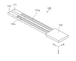
先ず、本発明に係る第1実施形態のドライエッチング方法を適用する音叉型水晶振動片の構成について説明する。図1に示すように音叉型水晶振動片100は、例えば水晶の単結晶から切り出され、ドライエッチング方法を用いて音叉型の外形形状に加工されている。この音叉型水晶振動片100は、X軸が電気軸、Y軸が機械軸、Z軸が光軸となるように水晶の単結晶から切り出される。このように電気軸がX軸方向に配置されることにより、高精度が要求される携帯電話装置等の電子機器全般に好適な音叉型水晶振動片100となる。また、水晶の単結晶から切り出す際、上述のX軸、Y軸およびZ軸からなる直交座標系において、X軸回りに、X軸とY軸とからなるXY平面を反時計方向に約1度ないし5度傾けた、所謂水晶Z板として、音叉型水晶振動片100が形成されている。
(Configuration of tuning-fork type crystal vibrating piece)
First, the configuration of a tuning fork type crystal vibrating piece to which the dry etching method according to the first embodiment of the present invention is applied will be described. As shown in FIG. 1, the tuning-fork type
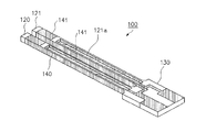
この音叉型水晶振動片100は、基部130と、この基部130からY軸方向に突出するように形成された例えば2本の振動腕である腕部120,121とを有している。腕部120の表面側には、溝部120aが設けられ、振動腕としての腕部121の表面側には、溝部121aが設けられている。また、振動腕としての腕部120の裏面側にも、溝部120aが設けられ、腕部121の裏面側にも、溝部121aが設けられている。
The tuning-fork type
なお、図1に示す音叉型水晶振動片100では、Z軸方向の厚みは、例えば約0.1mm程度となっており、腕部120,121の腕幅(X軸方向の幅)は、約0.1mm程度となっている。また、腕部120と腕部121との間隔は、約0.06mm程度となっている。溝部120a,121aの溝幅(X軸方向の幅)は、例えば約0.07mm程度であり、溝深さ(Z軸方向の深さ)は、例えば約0.02から0.045mm程度となっている。
In the tuning fork type
このように形成されている音叉型水晶振動片100には、図2に斜線で示されている部分に電極140,141が形成される。すなわち、電極140,141は、基部130から2本の腕部120,121にかけて配置されると共に、電極140,141は、腕部120,121の側面や溝部120a,121aにも配置されている。このように配置される電極140,141は、外部から電圧が印加されると電界を発生させ、圧電体である水晶の腕部120,121を振動させるようになっている。
In the tuning-fork type
以上のように形成されている音叉型水晶振動片100は、例えば共振周波数が32.768kHzで振動することができる。なお、上述の構成においては、音叉型水晶振動片100の厚みに対して、例えば腕部120と腕部121との間隔が狭い構成の外形形状が求められる。このような構成の音叉型水晶振動片100の外形形状を形成するためにドライエッチング方法が用いられる。ドライエッチング方法は、例えば図3に示すように、基板50上にマスクパターン53を形成し、マスクパターン53が形成されていない基板50の露出部51の部分を、反応ガスを用いたプラズマ型エッチング装置などによってエッチングする。以下、このドライエッチング方法を含む音叉型水晶振動片100の外形形成方法について、図4を参照しながら説明する。
The tuning-fork type
(音叉型水晶振動片の外形形成方法)
図4(a)、および図4(b)を参照して、第1レジスト102を形成する工程、および第2レジスト104を形成する工程について説明する。
先ず、第1レジスト102の形成に先立って、基板110を準備する工程において、図4(a)に示すように、所謂水晶Z板を板状に加工した基板110を準備する。そして、基板110の上面111にシード層105を形成する工程に進む。シード層105は、一例として下地層にクロム(Cr)を形成し、その上に銅(Cu)や金(Au)などが形成されている構成を用いる。シード層105の形成においては、真空蒸着法、真空スパッタリング法などを用いることができる。このようにシード層105を形成することにより、基板110とメッキ層103の密着性を高くすることができる。これにより、基板110とマスクを構成するメッキ層103とのエッチング速度の比であるエッチング選択比を高くすることができる。
(Outline forming method of tuning-fork type crystal vibrating piece)
With reference to FIG. 4A and FIG. 4B, the step of forming the first resist 102 and the step of forming the second resist 104 will be described.
First, in the step of preparing the
そして、図4(a)に示すように、シード層105の上面105fに、突出部となる第1レジスト102を形成する。第1レジスト102は、基板110をエッチングしない非エッチング領域、即ち、後述する金属メッキ層103(図4(c)参照)の両側に、第1の間隔W1を有して配置されている。第1レジスト102は、例えば、レジストをシード層105の上面105fに塗布した後、フォトリソグラフィー技術およびエッチング技術を用いてパターニングする。
Then, as shown in FIG. 4A, a first resist 102 that becomes a protrusion is formed on the
次に、図4(b)に示すように、非エッチング領域の両側に第2の間隔W2を有した壁面106を有し、第1レジスト102の一部と重なるように配置された第2レジスト104を形成する。即ち、第2レジスト104は、非エッチング領域の外側に位置する第1レジスト102と、第1レジスト102の外側に露出するシード層105の上面105fに亘って設けられている。このとき、第2の間隔W2は、第1レジスト102の内側の間隔である第1の間隔W1よりも広くなるように配置される。このように第2レジスト104が配置されることにより、断面視にて基板110側に位置する第1レジスト102の一部が、基板110と反対側に位置する第2レジスト104の壁面106から突出する突出部となる。なお、第2レジスト104においても、例えば、フォトリソグラフィー技術およびエッチング技術を用いてパターニングすることにより、第2レジスト104の形状を形成する。上述の第1レジスト102と第2レジスト104によって、レジスト層が構成されている。
Next, as shown in FIG. 4B, the second resist having the
上述のように、第2レジスト104、および第2レジスト104と一部が重なる第1レジスト102によって構成されたレジスト層を設けることにより、後述するメッキ層103(図4(d)参照)の基板110側(下部)に、凹部108(図4(d)参照)を容易に形成することができる。 As described above, by providing a resist layer composed of the second resist 104 and the first resist 102 partially overlapping with the second resist 104, a substrate of a plating layer 103 (see FIG. 4D) described later is provided. The concave portion 108 (see FIG. 4D) can be easily formed on the 110 side (lower portion).
なお、第1レジスト102および第2レジスト104は、樹脂材料を基材とするネガタイプあるいはポジタイプのいずれかのレジストを用いることができるが、本形態ではネガタイプのレジストを用いている。また、第2レジスト104の片側が非エッチング領域となる場合は、非エッチング領域側の第2レジスト104の片側に、第2レジスト104から突出する第1レジスト102が配置されればよい。 The first resist 102 and the second resist 104 can be either a negative type resist or a positive type resist based on a resin material, but in this embodiment, a negative type resist is used. When one side of the second resist 104 is a non-etched region, the first resist 102 protruding from the second resist 104 may be disposed on one side of the second resist 104 on the non-etched region side.
次に、マスクパターンとして機能するメッキ層103を形成する工程について説明する。図4(c)に示すように、メッキ層103は、第2レジスト104によって形成される第2の間隔W2の内側(非エッチング領域)に形成する。具体的にメッキ層103は、基板110側に第2レジスト104の壁面106から突出する突出部(第1レジスト102)と、非エッチング領域に露出するシード層105の上面105fに亘る第2の間隔W2の内側に設ける。メッキ層103は、金属メッキによって構成される。本形態におけるメッキ層103は、ニッケル(Ni)メッキによって形成されている。なお、メッキ層103を構成する他の金属としては、一例として銅(Cu)、金(Au)、チタン(Ti)、チタンタングステン(TiW)などを挙げることができる。
Next, the process of forming the
次に、第1レジスト102および第2レジスト104を剥離する工程について説明する。図4(d)に示すように、メッキ層103を残して、第1レジスト102および第2レジスト104を剥離する。第1レジスト102および第2レジスト104の剥離は、レジスト剥離液中に浸漬することによって行う。この第1レジスト102および第2レジスト104の剥離によって、メッキ層103は、基板110側と反対側(上面側)の両側に形成されている側面107を有し、その両側の側面107から凹む凹部108が基板110側に形成された構成としてシード層105上に残留する。即ち、メッキ層103は、断面視したときシード層105との接続部が凹む、所謂T字状の断面形状となっている。
Next, a process of removing the first resist 102 and the second resist 104 will be described. As shown in FIG. 4D, the first resist 102 and the second resist 104 are stripped leaving the
次に、シード層105をエッチングする工程について説明する。図4(e)に示すように、シード層105は、メッキ層103をマスクとして、例えばウェットエッチング法によって露出部分105b(被エッチング部位)がエッチングされて取り除かれる。そして、シード層105が取り除かれた部分は、基板110が露出し、メッキ層103の下部は残留部分105aとしてメッキ層103の下地層となる。
Next, the step of etching the
次に、基板110をドライエッチングする工程について説明する。図4(f)に示すように、基板110をドライエッチングする工程では、メッキ層103をマスクとして基板110の露出面に対してエッチングを開始し、被エッチング部位110bをエッチングすることによって音叉型水晶振動片100の構成部位110aを出現させ、音叉型水晶振動片100の外形形状を形成する。このとき、メッキ層103も、基板110のエッチング進行速度に比べ遅いエッチング速度でエッチングされる。このメッキ層103のエッチングされた部分を、図中にエッチング部位103bとして2点鎖線で示し、残った部位を残ったメッキ層103aとして示している。
Next, a process of dry etching the
ドライエッチングは、例えば四フッ化炭素(CF4)ガスなどの反応ガスを用いて基板110をエッチングする。本形態では、プラズマにより四フッ化炭素(CF4)ガスをイオン化・ラジカル化してエッチングする反応性イオンエッチングを用いた。このようなドライエッチングでは、エッチングがマスクの外形を境としてマスクの平面に対して垂直方向に進行するため、メッキ層103においては、その両側の側面に張り出した壁面107aがマスク境として機能する。したがって、メッキ層103の基板110側に凹部108が設けられていても、エッチング形状に対する影響は生じない。また、このドライエッチング工程においては、エッチングされた露出面に絶縁層を形成する、所謂デポジションを、エッチングの進行と同時、あるいは交互に行うことができる。なお、反応性ガスとして、例えば、六フッ化硫黄(SF6)、トリフルオロメタン(CHF3)などのガスを用いることができる。
In the dry etching, the
このような凹部108を有するメッキ層103をマスクとしてドライエッチングを行うことにより、基板110表面の微細な凹凸などによって生じるメッキ層103の側壁の凹凸が形成されなくなる。これにより、メッキ層103の側壁の凹凸よって生じる基板110のエッチング形状の寸法誤差の発生を防止することができる。
By performing dry etching using the
次に、メッキ層103およびシード層105を剥離する工程について説明する。前述のドライエッチングによって外形形状が形成された基板110から、メッキ層103とシード層105とをそれぞれの剥離液を用いて剥離する。これによって、図4(g)に示すように、音叉型水晶振動片100の外形形状、例えば2本の腕部120,121が形成される。
Next, the process of peeling the
なお、上述のドライエッチング加工においては、図5(a)に示すように、メッキ層103の凹部108の高さt3(換言すれば、凹部108を形成するためのレジストの突出部となる第1レジスト102の高さ)は、加工比率r(式(1))との関係から、以下の式(2)で求められる範囲にあることが好ましい。
加工比率r=基板110の加工量/メッキ層103の加工量L・・・(1)
としたとき、
凹部108(突出部)の高さt3<メッキ層103の厚みt2−(基板110の厚みt1/加工比率r)・・・(2)
なお、本実施形態における加工比率rは、10から20の範囲内となるように設定することが望ましく、本実施形態の音叉型水晶振動片100の外形形状を形成する場合では、加工比率rを15程度に設定している。
In the dry etching process described above, as shown in FIG. 5A, the height t3 of the
Processing ratio r = processing amount of
When
The height t3 of the recess 108 (protrusion) <the thickness t2- of the plating layer 103 (the thickness t1 / the processing ratio r of the substrate 110) (2)
In addition, it is desirable to set the processing ratio r in the present embodiment to be in the range of 10 to 20, and when forming the outer shape of the tuning fork type
凹部108(突出部)の高さt3を、上述の範囲内に設定することにより、基板110をドライエッチングする際にメッキ層103がエッチング(加工量L)されても、凹部108にまでエッチングが到達せず、凹部108を確実に形成することができる。
By setting the height t3 of the recess 108 (projection) within the above range, even when the
以上説明したような、ドライエッチング法を用いた音叉型水晶振動片100の外形形成方法によれば、第2レジスト104と、第2レジスト104と一部が重なる第1レジスト102によって形成される突出部によって、メッキ層103の基板110側(下部)に、凹部108を容易に形成することができる。
そして、このメッキ層103の基板110側の側面107に形成された凹部108により、基板110の上面111の微細な凹凸、あるいはレジストと基板110との熱膨張の違いなどがあってもメッキ層103の側面107から突出する凸部が形成されなくなり、この凸部の影響による基板110のエッチング形状の寸法ばらつきの発生を防止することができる。これにより、基板110のドライエッチングにおいて、所望の外形形状を精度良く形成することが可能となり、音叉型水晶振動片100の振動特性を向上させることが可能となる。
According to the outer shape forming method of the tuning fork type
The
<第2実施形態>
図6を用い、本発明に係るドライエッチング方法の第2実施形態を、音叉型水晶振動片の外形加工に適用する例を用いて説明する。図6(a)〜図6(g)は、音叉型水晶振動片の製造工程の内の第2実施形態に係る外形加工の工程を示す概略工程図である。なお、第2実施形態では、前述の第1実施形態と同じ音叉型水晶振動片を用いているため、同じ構成については同符号を付して構成の説明を省略する。
Second Embodiment
A second embodiment of the dry etching method according to the present invention will be described with reference to FIG. 6 using an example of applying to the outer shape processing of a tuning fork type crystal vibrating piece. FIG. 6A to FIG. 6G are schematic process diagrams showing the outer shape machining process according to the second embodiment in the manufacturing process of the tuning-fork type crystal vibrating piece. In the second embodiment, since the same tuning fork type crystal vibrating piece as in the first embodiment is used, the same components are denoted by the same reference numerals and description of the components is omitted.
(音叉型水晶振動片の外形形成方法)
第2実施形態の音叉型水晶振動片の外形形成方法は、メッキ層の基板側に設けられる凹部の形成方法が第1実施形態と異なる。したがって、以下の説明では、異なる工程について説明し、同様な工程の説明は省略する。
(Outline forming method of tuning-fork type crystal vibrating piece)
The method for forming the outer shape of the tuning-fork type crystal vibrating piece of the second embodiment is different from the method of forming the concave portion provided on the substrate side of the plating layer in the first embodiment. Therefore, in the following description, different steps will be described, and description of similar steps will be omitted.
先ず、図6(a)に示すように、所謂水晶Z板を板状に加工した基板110を準備する。そして、基板110の上面111にシード層105を形成する。シード層105は、第1実施形態と同様であるので説明を省略する。
First, as shown in FIG. 6A, a
そして、図6(a)に示すように、シード層105の上面105fに、レジスト層204を形成する。レジスト層204は、後にエッチング領域となる部位に形成される。レジスト層204は、例えば、レジストをシード層105の上面105fに塗布した後、フォトリソグラフィー技術およびエッチング技術を用いてパターニングする。レジスト層204は、樹脂材料を基材とするネガタイプあるいはポジタイプのいずれかのレジストを用いることができるが、本形態ではネガタイプのレジストを用いている。
Then, as illustrated in FIG. 6A, a resist
次に、図6(b)に示すように、断面視において、レジスト層204の基板110側(下部)の両側に突出部202を形成する工程について説明する。この工程では、パターン形成されたレジスト層204を、100℃程度に加熱することによって、レジスト層204の両側に突出部202を形成する。なお、この加熱処理は、レジスト層204を形成するフォトリソグラフィー処理の内で行うことができる。具体的には、レジスト層を塗布し、パターニング(露光、現像処理)後に行われるベーキング処理において、温度設定を適宜設定して行うことができる。したがって、この加熱処理のために、新たな工程の追加は不要である。
Next, as shown in FIG. 6B, a process of forming the
レジスト層204は、所定の温度、例えば100℃程度に加熱されると粘度が下がり、流動性が向上する。加熱され、流動性が高まったレジスト層204は、表面張力あるいは重力の影響などによって、基板110側(レジスト層204の下部)の側壁206に裾引き形状(フィレット状)の突出部202が出現する。その後、加熱を止めることによって突出部202として形成される。このように、レジスト層204を加熱することによって、突出部202を容易に形成することができる。
When the resist
次に、マスクパターンとしてのメッキ層203を形成する工程について説明する。図6(c)に示すように、メッキ層203は、レジスト層204の設けられていない領域、即ち非エッチング領域に相当する領域に設ける。メッキ層203は、金属メッキによって構成される。本形態におけるメッキ層203は、ニッケル(Ni)メッキによって形成されている。なお、メッキ層203を構成する他の金属としては、一例として銅(Cu)、金(Au)、チタン(Ti)、チタンタングステン(TiW)などを挙げることができる。
Next, a process for forming the
次に、レジスト層204を剥離する工程について説明する。図6(d)に示すように、メッキ層203を残して、レジスト層204を剥離する。レジスト層204の剥離は、レジスト剥離液中に浸漬することによって行う。このレジスト層204の剥離によって、メッキ層203は、基板110側と反対側(上面側)の両側に形成されている側面207を有し、その両側の側面207から裾引き形状(フィレット状)に凹む凹部208が基板110側に形成された構成としてシード層105上に残留する。即ち、メッキ層203は、断面視したときシード層105との接続部が裾引き形状に凹んでいる断面形状となっている。
Next, a process for removing the resist
次に、第1実施形態と同様に、メッキ層203をマスクとして、図6(e)に示すように、シード層105をエッチングし、図6(f)に示すように、基板110をドライエッチングすることによって音叉型水晶振動片100の外形形状を形成する。
図6(e)に示すように、シード層205は、メッキ層103をマスクとして、例えばウェットエッチング法によって露出部分205b(被エッチング部位)がエッチングされて取り除かれる。そして、シード層205が取り除かれた部分は、基板110が露出し、メッキ層203の下部は残留部分205aとしてメッキ層203の下地層となる。
図6(f)に示すように、基板110をドライエッチングする工程では、メッキ層203をマスクとして基板110の露出面に対してエッチングを開始し、被エッチング部位110bをエッチングすることによって音叉型水晶振動片100の構成部位110aを出現させ、音叉型水晶振動片100の外形形状を形成する。このとき、メッキ層203も、基板110のエッチング進行速度に比べ遅いエッチング速度でエッチングされる。このメッキ層103のエッチングされた部分を、図中にエッチング部位203bとして2点鎖線で示し、残った部位を残ったメッキ層203aとして示している。なお、ドライエッチングについては、第1実施形態と同様であるので説明を省略する。
Next, as in the first embodiment, using the
As shown in FIG. 6E, the seed layer 205 is removed by etching the exposed
As shown in FIG. 6 (f), in the step of dry etching the
このような凹部208を有するメッキ層203をマスクとしてドライエッチングを行うことにより、基板110表面の微細な凹凸などによって生じるメッキ層203の側壁の凹凸が形成されなくなる。これにより、メッキ層203の側壁の凹凸よって生じる基板110のエッチング形状の寸法誤差の発生を防止することができる。
By performing dry etching using the
次に、第1実施形態と同様に、ドライエッチングによって外形形状が形成された基板110からメッキ層203とシード層105とを剥離する。これによって、図6(g)に示すように、音叉型水晶振動片100の外形形状、例えば2本の腕部120,121が形成される。
Next, as in the first embodiment, the
なお、上述のドライエッチング加工においては、図5(b)に示すように、メッキ層203の凹部208の高さt3は、第1実施形態と同様に、加工比率r(式(1))との関係から、以下の式(2)で求められる範囲にあることが好ましい。なお、本第2実施形態における凹部208の高さは、レジストの突出部202となる裾引き形状の高さ、即ち凹部208と基板110の上面111との距離となる。第2実施形態での凹部208の高さは、基板110の上面111からメッキ層203の側面207が凹部208と交わる位置までの寸法である。
加工比率r=基板110の加工量/メッキ層203の加工量L・・・(1)
としたとき、
凹部208(突出部)の高さt3<メッキ層203の厚みt2−(基板110の厚みt1/加工比率r)・・・(2)
In the dry etching process described above, as shown in FIG. 5B, the height t3 of the
Processing ratio r = processing amount of
When
The height t3 of the recess 208 (protrusion) <the thickness t2 of the plating layer 203 (the thickness t1 / the processing ratio r of the substrate 110) (2)
凹部208(突出部)の高さt3を、上述の範囲内に設定することにより、基板110をドライエッチングする際にメッキ層203がエッチング(加工量L)されても、凹部208にまでエッチングが到達せず、凹部208を確実に形成することができる。
By setting the height t3 of the recess 208 (projection) within the above range, even when the
以上説明したような、第2実施形態に係るドライエッチング法を用いた音叉型水晶振動片100の外形形成方法によれば、レジスト層204に形成される突出部202によって、メッキ層203の基板110側(下部)に、裾引き形状の凹部208を容易に形成することができる。
そして、このメッキ層203の基板110側の側面207に形成された凹部208により、基板110の上面111の微細な凹凸、あるいはレジストと基板110との熱膨張の違いなどがあってもメッキ層203の側面207から突出する凸部が形成されなくなり、この凸部の影響による基板110のエッチング形状の寸法ばらつきの発生を防止することができる。これにより、基板110のドライエッチングにおいて、所望の外形形状を精度良く形成することが可能となり、音叉型水晶振動片100の振動特性を向上させることが可能となる。
According to the outer shape forming method of the tuning-fork type
The
上述では、基板110とメッキ層103との間にシード層105が設けられている例で説明したが、シード層105が設けられていない構成にも適用することができる。具体的には、基板110の上面111に、第1レジスト102、第2レジスト104、およびメッキ層103を設けることができる。
Although the example in which the
また、上述では、水晶基板を用いる音叉型水晶振動片100の外形形成方法を例に説明したが、本発明に係る基板のドライエッチング方法は、これに限らない。本発明に係る基板のドライエッチング方法は、例えば、半導体基板、ガラス基板などにも適用可能であり、水晶基板を用いる例としてはATカット水晶振動片などのタイミング素子やジャイロセンサー素子などのセンサー素子、半導体基板を用いる例としては半導体素子、あるいはガラス基板を用いる例としてはガラスパッケージ基板などに適用することができる。
In the above description, the method for forming the outer shape of the tuning-fork type
50…基板、51…露出部、53…マスクパターン、100…音叉型水晶振動片、102…第1レジスト、103,203…メッキ層、103a,203a…残ったメッキ層、103b,203b…メッキ層のエッチング部位、104…第2レジスト、105…シード層、105a…シード層の残留部分、105b…シード層の露出部分、105f…上面、106…第2レジストの壁面、107,207…側面、107a,207a…壁面、108,208…凹部、110…基板、110a…構成部位、110b…被エッチング部位、111…上面、120,121…腕部、120a,121a…溝部、130…基部、140,141…電極、202…突出部、204…レジスト層、206…レジスト層の壁面。
DESCRIPTION OF
Claims (5)
前記基板上に、断面視にて前記基板側に前記基板と反対側よりも突出している突出部を有するレジスト層を形成する工程と、
前記基板上に、メッキ層を形成する工程と、
前記メッキ層をマスクとして前記基板をドライエッチングする工程と、を含み、
前記レジスト層を形成する工程において、
パターン形成後のレジストを加熱することによって前記突出部を形成することを特徴とする基板のドライエッチング方法。 Preparing a substrate;
On the substrate, a step of forming a resist layer having a protruding portion protruding from the opposite side to the substrate on the substrate side in a sectional view;
Forming a plating layer on the substrate;
Look including the the steps of dry-etching the substrate with the plating layer as a mask,
In the step of forming the resist layer,
A method of dry etching a substrate, wherein the protrusion is formed by heating the resist after pattern formation .
前記第1レジストの前記基板とは反対側の面に、平面視で前記第1開口部と重なり、且つ前記第1の間隔より広い第2の間隔を備えた第2開口部を挟んで互いに離間している第3部分および第4部分を有する第2レジストを形成する工程と、 The surfaces of the first resist opposite to the substrate are spaced apart from each other across a second opening having a second interval wider than the first interval and overlapping the first opening in plan view. Forming a second resist having a third portion and a fourth portion,
前記第1開口部及び前記第2開口部に、メッキ層を形成する工程と、 Forming a plating layer on the first opening and the second opening;
前記メッキ層をマスクとして、前記基板をドライエッチングする工程と、 Using the plating layer as a mask, dry etching the substrate;
を含み、Including
前記メッキ層を形成する工程は、前記第3部分および前記第4部分に接する側面を有する前記メッキ層を形成する工程であり、 The step of forming the plating layer is a step of forming the plating layer having side surfaces in contact with the third portion and the fourth portion,
前記ドライエッチングする工程は、前記側面を前記マスクの境界として、前記基板に対して垂直にエッチングが進行するように前記ドライエッチングする工程であることを特徴とする基板のドライエッチング方法。 The method for dry etching a substrate, wherein the step of dry etching is a step of performing the dry etching so that the etching proceeds perpendicularly to the substrate with the side surface as the boundary of the mask.
前記突出部の高さt3は、
t3<前記メッキ層の厚さt2−(前記基板の厚さt1/前記加工比率r)
であることを特徴とする請求項1に記載の基板のドライエッチング方法。 When processing ratio r = processing amount of the substrate / processing amount of the plating layer,
The height t3 of the protrusion is
t3 <thickness t2- of the plating layer (thickness t1 / thickness ratio r of the substrate)
The method for dry etching a substrate according to claim 1, wherein:
前記第1部分および前記第2部分の高さt3は、 The height t3 of the first part and the second part is:
t3<前記メッキ層の厚さt2−(前記基板の厚さt1/前記加工比率r) t3 <thickness t2- of the plating layer (thickness t1 / thickness ratio r of the substrate)
であることを特徴とする請求項2に記載の基板のドライエッチング方法。 The method for dry etching a substrate according to claim 2, wherein:
Priority Applications (1)
| Application Number | Priority Date | Filing Date | Title |
|---|---|---|---|
| JP2014087149A JP6435629B2 (en) | 2014-04-21 | 2014-04-21 | Substrate dry etching method |
Applications Claiming Priority (1)
| Application Number | Priority Date | Filing Date | Title |
|---|---|---|---|
| JP2014087149A JP6435629B2 (en) | 2014-04-21 | 2014-04-21 | Substrate dry etching method |
Publications (3)
| Publication Number | Publication Date |
|---|---|
| JP2015207895A JP2015207895A (en) | 2015-11-19 |
| JP2015207895A5 JP2015207895A5 (en) | 2017-04-27 |
| JP6435629B2 true JP6435629B2 (en) | 2018-12-12 |
Family
ID=54604401
Family Applications (1)
| Application Number | Title | Priority Date | Filing Date |
|---|---|---|---|
| JP2014087149A Active JP6435629B2 (en) | 2014-04-21 | 2014-04-21 | Substrate dry etching method |
Country Status (1)
| Country | Link |
|---|---|
| JP (1) | JP6435629B2 (en) |
Family Cites Families (4)
| Publication number | Priority date | Publication date | Assignee | Title |
|---|---|---|---|---|
| JPH05243217A (en) * | 1992-02-28 | 1993-09-21 | Nec Corp | Manufacture of semiconductor device |
| JP3421259B2 (en) * | 1997-12-25 | 2003-06-30 | ティーディーケイ株式会社 | Etching mask, manufacturing method and etching method thereof, and magnetic head and manufacturing method thereof |
| JP4516538B2 (en) * | 2006-03-01 | 2010-08-04 | 住友電工デバイス・イノベーション株式会社 | Manufacturing method of semiconductor device |
| JP5386962B2 (en) * | 2008-12-12 | 2014-01-15 | 三菱電機株式会社 | Etching method and method of manufacturing semiconductor device using etching method |
-
2014
- 2014-04-21 JP JP2014087149A patent/JP6435629B2/en active Active
Also Published As
| Publication number | Publication date |
|---|---|
| JP2015207895A (en) | 2015-11-19 |
Similar Documents
| Publication | Publication Date | Title |
|---|---|---|
| US8093787B2 (en) | Tuning-fork-type piezoelectric vibrating piece with root portions having tapered surfaces in the thickness direction | |
| JP5059399B2 (en) | Method for manufacturing piezoelectric vibrating piece, piezoelectric vibrating piece and piezoelectric device | |
| JP5465573B2 (en) | Manufacturing method of tuning fork type crystal piece | |
| US20090236950A1 (en) | Manufacturing method of tuning-fork type quartz crystal resonator | |
| JP3952811B2 (en) | Piezoelectric vibrating piece, method for manufacturing piezoelectric vibrating piece, and piezoelectric device | |
| JP5468444B2 (en) | Manufacturing method of tuning fork type crystal piece | |
| JP2008113380A (en) | Method for manufacturing crystal vibrator, crystal vibrator, and electronic component | |
| JP6435629B2 (en) | Substrate dry etching method | |
| JP5465572B2 (en) | Manufacturing method of tuning fork type crystal piece | |
| JP5890271B2 (en) | Tuning fork-type bending crystal resonator element and manufacturing method thereof | |
| JPH07212161A (en) | Manufacture of crystal oscillator | |
| JP2007142795A (en) | Method of manufacturing piezoelectric vibration chip, and method of forming alignment marker | |
| JP2006314007A (en) | Method of manufacturing piezoelectric vibration piece, and the piezoelectric vibrator | |
| JP4305728B2 (en) | Manufacturing method of vibrating piece | |
| JP6055294B2 (en) | Method for manufacturing piezoelectric element | |
| JP5769557B2 (en) | Method for manufacturing crystal resonator element | |
| JP4729924B2 (en) | Method for producing AT-cut crystal piece assembly | |
| JP2010183208A (en) | Wet etching method and method for processing tuning fork type piezoelectric element strip | |
| JP2007096756A (en) | Forming method of substrate, crystal resonance chip, and gyro resonance chip | |
| JP2007166242A (en) | Manufacturing method of crystal blank, and crystal device using this crystal blank | |
| JP5758642B2 (en) | Manufacturing method of crystal unit | |
| JP6424076B2 (en) | Method for manufacturing piezoelectric vibrator | |
| JP6163404B2 (en) | Method for manufacturing piezoelectric element | |
| JP5045829B2 (en) | Quartz piece aggregate and quartz crystal resonator | |
| JPH0864931A (en) | Microelectrode forming method of electronic component |
Legal Events
| Date | Code | Title | Description |
|---|---|---|---|
| RD04 | Notification of resignation of power of attorney |
Free format text: JAPANESE INTERMEDIATE CODE: A7424 Effective date: 20160617 |
|
| RD03 | Notification of appointment of power of attorney |
Free format text: JAPANESE INTERMEDIATE CODE: A7423 Effective date: 20160624 |
|
| A521 | Written amendment |
Free format text: JAPANESE INTERMEDIATE CODE: A523 Effective date: 20170323 |
|
| A621 | Written request for application examination |
Free format text: JAPANESE INTERMEDIATE CODE: A621 Effective date: 20170323 |
|
| A977 | Report on retrieval |
Free format text: JAPANESE INTERMEDIATE CODE: A971007 Effective date: 20180228 |
|
| A131 | Notification of reasons for refusal |
Free format text: JAPANESE INTERMEDIATE CODE: A131 Effective date: 20180320 |
|
| A521 | Written amendment |
Free format text: JAPANESE INTERMEDIATE CODE: A523 Effective date: 20180517 |
|
| RD05 | Notification of revocation of power of attorney |
Free format text: JAPANESE INTERMEDIATE CODE: A7425 Effective date: 20180904 |
|
| TRDD | Decision of grant or rejection written | ||
| A01 | Written decision to grant a patent or to grant a registration (utility model) |
Free format text: JAPANESE INTERMEDIATE CODE: A01 Effective date: 20181016 |
|
| A61 | First payment of annual fees (during grant procedure) |
Free format text: JAPANESE INTERMEDIATE CODE: A61 Effective date: 20181029 |
|
| R150 | Certificate of patent or registration of utility model |
Ref document number: 6435629 Country of ref document: JP Free format text: JAPANESE INTERMEDIATE CODE: R150 |