JP6435522B2 - refrigerator - Google Patents
refrigerator Download PDFInfo
- Publication number
- JP6435522B2 JP6435522B2 JP2017102205A JP2017102205A JP6435522B2 JP 6435522 B2 JP6435522 B2 JP 6435522B2 JP 2017102205 A JP2017102205 A JP 2017102205A JP 2017102205 A JP2017102205 A JP 2017102205A JP 6435522 B2 JP6435522 B2 JP 6435522B2
- Authority
- JP
- Japan
- Prior art keywords
- glass plate
- refrigerator
- urethane
- resin film
- adhesive
- Prior art date
- Legal status (The legal status is an assumption and is not a legal conclusion. Google has not performed a legal analysis and makes no representation as to the accuracy of the status listed.)
- Active
Links
Images


Description
本発明は冷蔵庫に関し、特に冷蔵庫の扉構成に関するものである。 The present invention relates to a refrigerator, and particularly to a refrigerator door configuration.
一般にこの種の冷蔵庫は、断熱性を有する冷蔵庫本体内に冷蔵室、冷凍室、野菜室等を設け、これら各冷蔵室、冷凍室、野菜室等は扉によって開閉可能に構成してある。 In general, this type of refrigerator is provided with a refrigerator compartment, a freezer compartment, a vegetable compartment, etc. in a refrigerator body having heat insulation properties, and each of these refrigerator compartments, freezer compartments, vegetable compartments, etc. can be opened and closed by a door.
上記扉は、冷蔵庫本体の前面となる前板と、冷蔵室、冷凍室、野菜室等の内面となる内箱フレームと、これら前板と内箱フレームとを一体に連結する枠体と、の間にウレタンを充填発泡させて、冷蔵庫本体と同様断熱性を有するように構成してある。 The door includes a front plate that is a front surface of the refrigerator body, an inner box frame that is an inner surface of a refrigerator compartment, a freezer compartment, a vegetable compartment, and the like, and a frame that integrally connects the front plate and the inner box frame. Urethane is filled and foamed between them, and it is configured to have heat insulating properties like the refrigerator body.
このような冷蔵庫にあって、その扉の前板は冷蔵庫全体の見栄え、すなわち意匠に大きな影響を与え、その仕上がりは冷蔵庫全体の品位を大きく左右する。 In such a refrigerator, the front plate of the door greatly affects the appearance of the entire refrigerator, that is, the design, and the finish greatly affects the quality of the entire refrigerator.
そこでこの扉の意匠性を向上させるべく扉の前板をガラス板で構成したものが見られる(例えば、特許文献1参照)。 In view of this, there is a structure in which the front plate of the door is made of a glass plate in order to improve the design of the door (for example, see Patent Document 1).
図9は上記特許文献1で提案された扉を示し、その前板101は模様等の着色層102をシルク印刷によって形成した着色ガラス板103で構成してあり、当該着色ガラス板103と内箱フレーム104と枠体105との間にウレタン106を充填発泡させて構成してある。
FIG. 9 shows a door proposed in the above-mentioned
上記従来の構成によれば、着色層102の手前に着色ガラス板103の透明層が位置するため、着色の色に深みが加わって質感が増し、金属製あるいは樹脂製の塗装前板に比べるとその意匠性が向上する利点がある。
According to the above conventional configuration, since the transparent layer of the
しかしながら、上記従来の扉は枠体105に着色ガラス板挿入部107を設け、この着色ガラス板挿入部107に前記着色ガラス板103をはめ込んでいたため、この着色ガラス板挿入部107の縁部が着色ガラス板103の前面周囲に露出し、着色ガラス板103を用いて向上させた意匠性を損なうという課題があった。
However, since the conventional door is provided with the colored glass
また、この着色ガラス板挿入部107の縁部と着色ガラス板103との境界部にはごく微細な誇りや塵埃等が付着堆積していき、この微細なほこりや塵埃等は拭きとろうとしても完全にふき取ることができず、縁部に沿って線状に見え始めるようになる。これは着色ガラス板103の着色が白色系であれば短期間の使用で目立ちはじめ、使用期間が長くなるにつれて大きく目立つようになり、冷蔵庫の美観を大きく損ねる。
In addition, very fine pride and dust are deposited on the boundary between the colored glass
そこで出願人はこのような課題を解決すべく、枠体105の着色ガラス挿入部107を廃止して、着色ガラス板103の端部をそのまま露出状態とすることが考えてみた。
Therefore, in order to solve such a problem, the applicant considered that the colored
このような構成とした場合、着色ガラス板103は発泡ウレタン106との接着力によ
ってのみ保持することになり、金属製あるいは樹脂製前板に比べ重量が大きい着色ガラス板103を長期間に亘って確実に発泡ウレタン106に接着保持させる保障が必要になってくる。
In such a configuration, the
そこで出願人は上記着色ガラス板103と発砲ウレタン106との接着力の寿命加速試験を行ってみた。その結果、上記ガラス板103にシルク印刷等で形成した着色層はガラス板との接着強度にばらつきがあり、発泡ウレタン106の熱収縮や経年変化等で接着状態が劣化すると、着色層102が発泡ウレタン106とともにガラス板から剥がれ、ガラス板と発泡ウレタン106との間の接着強度を長期間に亘って保障することが困難であることが判明した。
Therefore, the applicant tried a life acceleration test of the adhesive force between the
本発明はこのような点に鑑みてなしたもので、ガラス板等の透明前板の接着強度を長期間に亘って保障でき、かつ、意匠性を高め、その高い意匠性を維持し続けることができる扉付の冷蔵庫を提供するものである。 The present invention has been made in view of the above points, and can ensure the adhesive strength of a transparent front plate such as a glass plate over a long period of time, and enhance the design and maintain its high design. A refrigerator with a door is provided.
本発明は上記目的を達成するため、本発明の冷蔵庫は、断熱性能を有する冷蔵庫本体と、前記冷蔵庫本体内に設けた貯蔵室と、前記貯蔵室の開口部を開閉可能とする断熱扉とを備える冷蔵庫であって、前記断熱扉は、内箱フレームと、縁枠と、ガラス板と、前記内箱フレームと前記縁枠と前記ガラス板との間の空間に充填発泡させたウレタンとを備え、前記ガラス板は前記ウレタンによって接着保持され、前記縁枠は、前記ガラス板の下端面に位置する部分に前記ガラス板を支持するための支持片を備え、前記支持片は、前記ガラス板の前面よりも前記冷蔵庫の庫内側に位置するものである。
In order to achieve the above object, the refrigerator of the present invention includes a refrigerator main body having heat insulation performance, a storage chamber provided in the refrigerator main body, and a heat insulating door capable of opening and closing the opening of the storage chamber. The heat insulating door includes an inner box frame, an edge frame, a glass plate, and urethane filled and foamed in a space between the inner box frame, the edge frame, and the glass plate. the glass plate is bonded held by said urethane, said edge frame is provided with a support piece for supporting the glass plate at a portion located at the lower end surface of the glass plate, and the support piece, of the glass plate It is located on the inner side of the refrigerator than the front.
これにより、ガラス板の接着強度を維持保障することができ、信頼性の高いものとすることができるとともに、扉の意匠性および安全性を高めることができる。
Thereby, the adhesive strength of the glass plate can be maintained and ensured, and the reliability can be enhanced, and the design and safety of the door can be enhanced.
本発明は、透明前板と発泡ウレタンとの接着力を長期間に亘って維持でき、かつ、意匠性を高め、更にその高い意匠性を長く保持できる扉付の冷蔵庫を提供することができる。 ADVANTAGE OF THE INVENTION This invention can provide the refrigerator with a door which can maintain the adhesive force of a transparent front board and foaming urethane over a long period of time, can improve the designability, and can also hold | maintain the high designability for a long time.
第1の発明は、断熱性能を有する冷蔵庫本体と、前記冷蔵庫本体内に設けた貯蔵室と、前記貯蔵室の開口部を開閉可能とする断熱扉とを備える冷蔵庫であって、前記断熱扉は、内箱フレームと、縁枠と、ガラス板と、前記内箱フレームと前記縁枠と前記ガラス板との間の空間に充填発泡させたウレタンとを備え、前記ガラス板は前記ウレタンによって接着保持され、前記縁枠は、前記ガラス板の下端面に位置する部分に前記ガラス板を支持するための支持片を備え、前記支持片は、前記ガラス板の前面よりも前記冷蔵庫の庫内側に位置することにより、ガラス板と発泡断熱材との接着力を長期間に亘って維持でき、かつ、意匠性を高め、更にその高い意匠性を長く保持できる扉付の冷蔵庫を提供することができる。また第2の発明は、前記ガラス板の内面側に樹脂フィルムが設けられ、前記ウレタンは、前記樹脂フィルムを介して前記ガラス板を接着保持するものであり、第3の発明は前記樹脂フィルムの内面側に着色層が設けられているものである。よって、扉の意匠性および安全性を高めることができる。 1st invention is a refrigerator provided with the refrigerator main body which has heat insulation performance, the storage chamber provided in the said refrigerator main body, and the heat insulation door which can open and close the opening part of the said storage chamber, Comprising: The said heat insulation door is the said heat insulation door. An inner box frame, an edge frame, a glass plate, and urethane filled and foamed in a space between the inner box frame and the edge frame and the glass plate, and the glass plate is bonded and held by the urethane. is, the edge frame is provided with a support piece for supporting the glass plate at a portion located at the lower end surface of the glass plate, the support piece is located in compartment inside the refrigerator than the front surface of the glass plate By doing so, the refrigerator with a door which can maintain the adhesive force of a glass plate and a foam heat insulating material over a long period of time, can improve the design property, and can also hold | maintain the high design property for a long time can be provided. According to a second aspect of the present invention, a resin film is provided on the inner surface side of the glass plate , and the urethane adheres and holds the glass plate via the resin film. in which the colored layer is provided on the inner surface side. Therefore, the designability and safety of the door can be improved.
以下、本発明の実施の形態について、図面を参照しながら説明する。なお、この実施の形態によって本発明が限定されるものではない。 Hereinafter, embodiments of the present invention will be described with reference to the drawings. Note that the present invention is not limited to the embodiments.
(実施の形態1)
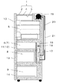
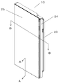
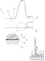
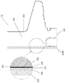
図1は本発明の実施の形態1における冷蔵庫の外観斜視図、図2は同冷蔵庫の断面図、図3は同冷蔵庫の扉の一つを示す斜視図、図4は同冷蔵庫の扉の分解斜視図、図5は同図3のA−A断面図、図6は同図3のB−B断面図である。
(Embodiment 1)
1 is an external perspective view of the refrigerator according to
図1、図2において、冷蔵庫本体1は、前方に開口する金属製(例えば鉄板)の外箱2と、硬質樹脂製(例えばABS)の内箱3と、これら外箱2と内箱3との間に発泡充填した硬質の発泡ウレタン4からなる。上記冷蔵庫本体1は、その内部に、冷蔵室5と、冷蔵室5の下に位置する切替室6及び切替室6に並設した製氷室7と、切替室6及び製氷室7の下部に位置する冷凍室8と、冷凍室8の下部に位置する野菜室9とを有する。また、前記冷蔵室5の前面は、例えば観音開き式の扉10,10により開閉自由に閉塞し、切替室6及び製氷室7と冷凍室8と野菜室9の前面部は引き出し式の扉11,12,13,14によって開閉自由に閉塞してある。
1 and 2, the
冷蔵庫本体1の背面には冷却室16があり、冷気を生成する冷却器17と、冷気を各室に供給する送風ファン18とが設けてある。また、上記冷蔵庫本体1の本体天面奥部には圧縮機19が設けてあり、コンデンサ(図示せず)と、放熱用の放熱パイプ20と、キャピラリーチューブ21と、前記した冷却器17とを順次環状に接続してなる冷凍サイクルに冷媒を封入し、冷却運転を行うように構成してある。
There is a
ここで、上記各扉10〜14は冷蔵庫本体1と同様硬質のウレタンを発泡充填して断熱性を持たせてあり、更に意匠性を向上させるべくその前面をガラス板等の透明前板で構成してある。
Here, each of the
以下、扉10を例にしてその構成について図3〜図6を用いて説明する。なお、扉10以外の扉11〜14も同様の構成である。
Hereinafter, the structure of the
図3〜図6において、23は冷蔵庫本体1の内側に位置することになる内箱フレームで、例えばABS樹脂で形成してある。24はこの内箱フレーム23の周端面に結合固定した縁枠で、ABS樹脂で形成してある。25は前記内箱フレーム23を覆うようにその縁枠24に積層配置したガラス板等の透明前板(以下、ガラス板と称す)で、この実施の形態では光沢のある強化ガラス板で形成してある。
3 to 6,
このガラス板25は、図5、図6に示すようにその内面に接着剤26を介して樹脂フィルム27が貼り付けてあり、この樹脂フィルム27に絵模様、例えばヘアーラインのような金属調模様からなる着色層28が形成してある。これによって、前記ガラス板25は、あたかも着色層付きのガラス板となる。前記樹脂フィルム27はこの実施の形態では透明
性が高く機械的強度の高いポリエチレンテレフタレートを用い、着色層28はホワイト系ではガラス板25とは反対側面に形成し、グレー系ではガラス板25側に形成してある。図面ではガラス板25とは反対側面に形成した場合を示している。
As shown in FIGS. 5 and 6, the
なお、ヘアーラインを立体的に強調する場合には、ガラス板25側に形成した着色層とは反対側の樹脂フィルムの表面に凹凸状の溝を設けて立体形状のヘアーラインを形成し、その表面にクロム蒸着層を形成する。これにより、意匠性を向上できるとともに、蒸着層の材料をクロムとすることで、フィルムと蒸着層の端面を起点とする蒸着層の錆発生を防止でき、模様の耐久性を向上させる効果がある。
In addition, when emphasizing the hairline three-dimensionally, a concave and convex groove is provided on the surface of the resin film opposite to the colored layer formed on the
29は前記ガラス板25の樹脂フィルム27側の面と内箱フレーム23と縁枠24との間の空間に充填発泡させた硬質のウレタンで、発泡によって内箱フレーム23及び縁枠24とともに前記ガラス板25内面の樹脂フィルム27に接着し、当該樹脂フィルム27を介してガラス板25を接着保持している。
29 is a hard urethane filled and foamed in a space between the surface of the
ここで、前記発泡ウレタン29はその発泡密度をガラス板25の中央部分より外周部分の方を高く設定してある。
Here, the foamed
また、前記内箱フレーム23の縁枠24は従来例で説明したような着色ガラス板挿入部を有しておらず、前記ガラス板25はその外周縁が図6に示すように縁枠24の端面24aと同一か若干内側に位置、この実施の形態では若干内側に位置させただけの構成としてある。
Further, the
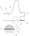
加えてこの実施の形態では、図5に示すように前記内箱フレーム23の縁枠24のうち、ガラス板25の下端面に位置する部分には、当該ガラス板25の前面から前方に略飛び出すことのない程度の寸法であるガラス板25の前面から前方に2mm以内の飛び出し代にてガラス板下端面に重合する透明前板支持片(以下、ガラス板支持片と称す)24bを設け、ガラス板25の重量を支えるように構成してある。
In addition, in this embodiment, as shown in FIG. 5, a portion of the
上記構成において、この冷蔵庫の扉10は、ヘアーラインのような金属調模様からなる着色層28がガラス板25及び樹脂フィルム27からなる透明層の内側に位置するため、着色の色に深みが加わり、その意匠性は金属製あるいは樹脂製の塗装前板に比べると大きく向上する。特にこの実施の形態では前記着色層28は樹脂フィルム27に形成しているので、ローラ等によって形成することができ、ガラス板に直接着色層をシルク印刷するものでは不良率が高くて実質的には得られなかったようなヘァーライン等の精細な模様も形成できて、その意匠性を格段に向上させることができる。
In the above-described configuration, the
あわせて着色層28はローラ等によって形成することができるので、樹脂フィルム27に対する接着強度を管理保障することができ、発泡ウレタンの熱収縮や経年変化等による接着状態の劣化が生じても樹脂フィルム27に対し剥がれることを確実に防止できるようになる。
In addition, since the
これにより、樹脂フィルム27をガラス板25と発泡ウレタン29との間に位置させてこれら両者を発泡ウレタン29及び接着剤26の接着力によって接着させたとき、着色層28が樹脂フィルム27から剥がれてこの剥がれに起因してガラス板25が発泡ウレタン29から剥離等するのを防止することができる。よって、長期間に亘ってフィルム付きガラス板25の接着強度を維持保障することができ、信頼性を確保することができる。
As a result, when the
加えてこの実施の形態では、発泡ウレタン29の発泡密度をガラス板25の中央部分より外周部分の方が高くなるようにしてあるから、発泡ウレタン29の接着力はガラス板2
5の外周部分のほうが強くなる。これにより、ガラス板25の樹脂フィルム27と発泡ウレタン29との接着力を長期間に亘ってより確実に維持保障することができる。
In addition, in this embodiment, the foaming density of the
The outer peripheral portion of 5 is stronger. Thereby, the adhesive force between the
すなわち、冷蔵庫は内部と外部で温度差が激しく、扉の開閉時に内部からの冷気によって扉のガラス板25端部は結露や激しい温度変化の影響を受ける。また、使用者の使い方によっては、開閉時に激しい衝撃を扉に与えたり、収納物の出し入れ時にガラス板25を含む扉に水や汁を溢す使用実態となる。そして、このような冷蔵庫特有の使用環境・実態によってガラス板25の端部は当該ガラス板端部を覆うガラス板挿入部が無いと発泡ウレタン29から剥がれやすい環境となっている。
That is, the refrigerator has a large temperature difference between the inside and the outside, and the end of the
このような環境下において、この発明では、ガラス板25の端部、すなわち、周囲部は、発泡ウレタン29の発泡密度が高い、すなわちごく微細に発泡しているウレタンスキン層との接着となっていて、発泡ウレタン29とガラス板25の樹脂フィルム27との接着密度は高く強固なものとなっている。したがって、長期間の使用に際してもガラス板25の樹脂フィルム27と発泡ウレタン29との接着は確保され、長期間フィルム付きガラス板25の接着強度を維持保障することができ、信頼性を確保できるのである。
Under such circumstances, in the present invention, the end portion of the
このガラス板25と発泡ウレタン29との接着力は寿命加速試験を行った結果、その接
着力は1.0g/cm2以上、好ましくは2.6g/cm2以上とすることにより、発泡ウレタン29の熱収縮等の経年変化による接着力劣化があっても確実に樹脂フィルム27と発泡ウレタン29との接着強度を保障することができ、ひいてはガラス板25の接着強度を長期間に亘って維持保障することができて、信頼性の高いものとすることができた。
The adhesive force between the
上記接着力の測定方法は、接着剤の重ね合わせせん断接着強さの標準的な測定方法である「JIS K 6850(接着剤−剛性被着材の引張せん断 接着強さ試験方法)」に基づく。 The method for measuring the adhesive force is based on “JIS K 6850 (Adhesive—Tensile Shear Adhesive Tensile Shear Adhesive Strength Test Method)”, which is a standard method for measuring the overlapping shear adhesive strength of an adhesive.
またこの実施の形態では樹脂フィルム27をポリエチレンテレフタレートフィルムで形成しており、このポリエチレンテレフタレートは機械的強度が高いので、フィルム自体が発泡ウレタン29の熱収縮に伴う経年変化で破れ、この破れた部分から樹脂フィルム27の発泡ウレタン29への接着の剥離が経年的に進行するのを防止でき、その接着強度維持保障の信頼性を確保することができる。
In this embodiment, the
一方、この扉は、上記接着強度の維持保障によって従来のガラス板周縁部を覆うガラス板挿入部等を廃止することができるから、ガラス板挿入部があるもののように意匠性を損なうことがなく、全面フラット感のあるすっきりとした外観にすることができる。また、ガラス板挿入部とガラス板との間の境界部にほこりや塵埃等が付着堆積してこれが線状に目立ってくることもなく、長期間に亘って初期の高い意匠性をそのまま維持することができる。 On the other hand, since this door can abolish the conventional glass plate insertion portion covering the peripheral edge of the glass plate by maintaining the adhesive strength, it does not impair the design like the one with the glass plate insertion portion. It is possible to have a clean appearance with a flat feeling on the entire surface. In addition, dust or dust adheres and accumulates at the boundary between the glass plate insertion portion and the glass plate, and this does not stand out linearly, maintaining the initial high design as it is for a long period of time. be able to.
更にこの実施の形態では、前記内箱フレーム23の縁枠24のうち、ガラス板25の下端面に位置する部分には当該ガラス板25の前面から前方に略飛び出すことなくガラス板下端面に重合するガラス板支持片24bが位置しているから、ガラス板25はその重量を内箱フレーム23の縁枠24のガラス板支持片24bによって支持されることになる。よって、万が一、発泡ウレタン29によるガラス板25の接着力の劣化によってガラス板25の剥がれが部分的に生じるようなことがあったとしても、ガラス板25が落下する等の異常事態は確実に防止でき、安心感が大きく向上する。また、前記縁枠24のガラス板支持片24bはガラス板前面より略飛び出すことがないので、ガラス板挿入部のように扉前面から見えることもなく、意匠性及び全面フラット感は良好なまま維持できる。また、拭
きとり時にごみがたまらない程度の微少な出っ張りであれば、ほこりや塵埃の非付着効果がかわらないのは言うまでもない。
Further, in this embodiment, a portion of the
特にこの実施の形態ではガラス板25はその外周縁が縁枠24の端面24aより若干内側に位置する構成としてあるから、このガラス板25の外周縁を縁枠24の端面24aが保護することになる。よって、例えば生産ラインでの扉搬送時やユーザ宅における扉交換サービス時にガラス板25の外周縁が何らかの物に当たって割れたりするようなことを防止することもできる。すなわち、ガラス板25を保持するためのガラス板挿入部を廃止してもガラス板外周部の破損を防止することができ、安心して使用することができる。
In particular, in this embodiment, since the outer peripheral edge of the
また、仮にガラス板25に何らかの外力が加わって万が一割れることがあっても、このガラス板片は樹脂フィルム27に接着していて飛散を防止されることになり、万が一のときの安全性も向上する。
Even if some external force is applied to the
(実施の形態2)
図7は実施の形態2における扉の断面図である。この実施の形態2はガラス板25の樹脂フィルム27と発泡ウレタン29との接着力を更に高めたものである。
(Embodiment 2)
FIG. 7 is a sectional view of a door in the second embodiment. In the second embodiment, the adhesive force between the
すなわち、樹脂フィルム27の発泡ウレタン側の面にも接着剤30を塗布しておき、この接着剤30の上からウレタンを充填発泡させて、樹脂フィルム27と発泡ウレタン29とを接着剤30を介して接着した構成としてある。
That is, the adhesive 30 is also applied to the surface of the
これにより、ウレタンの発泡密度が低くて発泡ウレタン29と樹脂フィルム27との実質接着面積が減少するガラス板中央部分での接着強度も向上させることができる。すなわち、ウレタンの発泡密度が低くて発泡ウレタン29と樹脂フィルム27との実質接着面積が減少する分をこの接着剤30による接着でカバーして、発泡ウレタン29と樹脂フィルム27との接着強度をより確実に確保することができ、ひいてはガラス板25の接着強度を長期間に亘って維持保障することができ、信頼性の高いものとすることができる。
Thereby, the adhesive strength in the center part of the glass plate where the foaming density of urethane is low and the substantial adhesion area between the
また、上記樹脂フィルム27と発泡ウレタン29との接着面はミクロ的に見ると発泡ウレタンのスキン層と樹脂フィルム27とが接着しており、このようなスキン層と樹脂フィルム27とはその双方の表面が滑面となっているため、剥がれかけると一気に剥がれてしまう危険性がある。特に、ガラス板外周部分の発泡密度を高めてその接着面をスキン層とした場合にあってはガラス板外周部分で剥がれが広がってしまう恐れがある。
In addition, when the microscopic surface of the adhesive surface between the
しかしながら、この実施の形態のように樹脂フィルム27の発泡ウレタン29との密着面に接着剤30を介在させると、樹脂フィルム27と発泡ウレタン29との接着強度が高いものとなり、前記したような発泡ウレタン29のスキン層と樹脂フィルム27との剥がれの広がりを防止できる。
However, when the adhesive 30 is interposed between the adhesive surface of the
特にこの実施の形態で例示したように上記接着剤30としてウレタン系接着剤またはポリエステル系の接着剤を用いると、当該ウレタン系またはポリエステル系の接着剤を構成するウレタンまたはポリエステルは、その溶解性パラメータ(以下、SP値と称す)がウレタンのSP値10〜11及びフィルムの材料であるポリエチレンテレフタレートのSP値11.3と近いので、これら相互間の接着力はより強固なものとなり、その接着強度維持はきわめて高いものとなる。換言するとポリエステル系(アクリル系も同様)樹脂は末端に−OH基をイソシアネートで反応させていて、ウレタン変成樹脂膜となっており、一方、ウレタン発泡材はポリエーテルポリオールのイソシアネート硬化であることから、基本の樹脂骨格は異なるものの反応内容は同じであるため、接着強度が向上するのである。よって、ガラス板25の接着強度を長期間に亘って維持保障することができ、信頼性を一
段と高めることができる。
In particular, as illustrated in this embodiment, when a urethane adhesive or a polyester adhesive is used as the adhesive 30, the urethane or polyester constituting the urethane or polyester adhesive has its solubility parameter. (Hereinafter referred to as the SP value) is close to the SP value 10-11 of urethane and the SP value 11.3 of polyethylene terephthalate, which is the film material, so that the adhesive strength between these becomes stronger and the adhesive strength thereof. Maintenance is extremely high. In other words, a polyester-based resin (also acrylic-based resin) has an —OH group reacted with an isocyanate at the end to form a urethane-modified resin film, while a urethane foam is an isocyanate-cured polyether polyol. Although the basic resin skeleton is different, the reaction content is the same, so the adhesive strength is improved. Therefore, the adhesive strength of the
(実施の形態3)
図8は実施の形態3における扉の断面図である。この実施の形態3ではガラス板25の樹脂フィルム27と内箱フレーム23の縁枠24とを更に両面テープ33によって接着したものである。
(Embodiment 3)
FIG. 8 is a sectional view of a door in the third embodiment. In the third embodiment, the
これにより、ガラス板25は発泡ウレタン29との接着に加え両面テープ33を介して縁枠24にも接着されることになる。よって、ガラス板25は樹脂フィルム27を介して発泡ウレタン29と縁枠24の両方に強力に接着保持されることになり、長期間に亘ってガラス板25の接着強度を維持保障することができ、更に信頼性の高いものとすることができる。
As a result, the
以上、本発明の主な実施形態を説明したが、上記実施の形態は本発明を実施するうえでの一例として示したものであり、本発明の目的を達成する範囲内で種々変更可能であることは言うまでもない。 As mentioned above, although main embodiment of this invention was described, the said embodiment was shown as an example in implementing this invention, and can be variously changed within the range which achieves the objective of this invention. Needless to say.
例えば、ガラス板を透明樹脂板に置き換えても良く、これによって軽量化による接着強度の更なる保障が可能となり、しかも低コスト化を図ることができる。また、樹脂フィル
ムも着色層の接着強度を管理保障できるものであればポリエチレンテレフタレート以外のものであっても良いものである。
For example, the glass plate may be replaced with a transparent resin plate, which makes it possible to further secure the adhesive strength by reducing the weight and to reduce the cost. Further, the resin film may be other than polyethylene terephthalate as long as the adhesive strength of the colored layer can be controlled.
更に、樹脂フィルム27の着色層28はすでに述べている通りガラス板側であっても良く、また、樹脂フィルム27と発泡ウレタン29との接着強度を向上させるために用いる接着剤30としてウレタンバインダー或いは蒸着層を用いても良く、或いは当該接着剤30と発泡ウレタン29との間に更に蒸着層或いはウレタンバインダー或いはその双方を介在させても良く、必要に応じて用いることによって接着強度や着色層の意匠性を向上させることができる。
Further, the
以上のように本発明は、扉の透明前板と発泡ウレタンとの接着力を長期間に亘って保障でき、かつ、意匠性を高め、更にその高い意匠性を長く保持することができ、一般用はもちろん業務用の冷蔵庫やワインクーラーにも幅広く適用できる。 As described above, the present invention can guarantee the adhesive force between the transparent front plate of the door and the urethane foam over a long period of time, can enhance the designability, and can maintain the high designability for a long time. Of course, it can be widely applied to commercial refrigerators and wine coolers.
1 冷蔵庫本体
2 外箱
3 内箱
4 ウレタン
5 冷蔵室
6 切替室
7 製氷室
8 冷凍室
9 野菜室
10,11,12,13,14 扉
16 冷却室
17 冷却器
18 送風ファン
19 圧縮機
20 放熱パイプ
21 キャピラリーチューブ
23 内箱フレーム
24 縁枠
24a 端面
24b 透明前板支持片(ガラス板支持片)
25 透明前板(ガラス板)
26 接着剤
27 樹脂フィルム
28 着色層
29 発泡ウレタン
30 接着剤
33 両面テープ
DESCRIPTION OF
25 Transparent front plate (glass plate)
26 Adhesive 27
Claims (3)
The refrigerator according to claim 2, wherein a colored layer is provided on an inner surface side of the resin film.
Priority Applications (1)
| Application Number | Priority Date | Filing Date | Title |
|---|---|---|---|
| JP2017102205A JP6435522B2 (en) | 2017-05-24 | 2017-05-24 | refrigerator |
Applications Claiming Priority (1)
| Application Number | Priority Date | Filing Date | Title |
|---|---|---|---|
| JP2017102205A JP6435522B2 (en) | 2017-05-24 | 2017-05-24 | refrigerator |
Related Parent Applications (1)
| Application Number | Title | Priority Date | Filing Date |
|---|---|---|---|
| JP2012198237A Division JP6167277B2 (en) | 2012-09-10 | 2012-09-10 | refrigerator |
Related Child Applications (1)
| Application Number | Title | Priority Date | Filing Date |
|---|---|---|---|
| JP2018075898A Division JP2018112399A (en) | 2018-04-11 | 2018-04-11 | refrigerator |
Publications (3)
| Publication Number | Publication Date |
|---|---|
| JP2017142065A JP2017142065A (en) | 2017-08-17 |
| JP2017142065A5 JP2017142065A5 (en) | 2018-03-22 |
| JP6435522B2 true JP6435522B2 (en) | 2018-12-12 |
Family
ID=59627753
Family Applications (1)
| Application Number | Title | Priority Date | Filing Date |
|---|---|---|---|
| JP2017102205A Active JP6435522B2 (en) | 2017-05-24 | 2017-05-24 | refrigerator |
Country Status (1)
| Country | Link |
|---|---|
| JP (1) | JP6435522B2 (en) |
Family Cites Families (7)
| Publication number | Priority date | Publication date | Assignee | Title |
|---|---|---|---|---|
| JP2004044980A (en) * | 2002-07-15 | 2004-02-12 | Toshiba Corp | Refrigerator door |
| JP2007120795A (en) * | 2005-10-25 | 2007-05-17 | Toshiba Corp | Refrigerator |
| KR101307862B1 (en) * | 2008-08-05 | 2013-09-12 | 삼성전자주식회사 | Door of Refrigerator and Method Of Manufacturing Same |
| DE102009052557A1 (en) * | 2009-06-05 | 2010-12-09 | Liebherr-Hausgeräte Ochsenhausen GmbH | Fridge and / or freezer |
| KR20110042786A (en) * | 2009-10-20 | 2011-04-27 | 삼성전자주식회사 | Refrigerator and method of manufacturing same |
| JP2013234832A (en) * | 2012-04-09 | 2013-11-21 | Asahi Glass Co Ltd | Door body of refrigerator |
| JP6167277B2 (en) * | 2012-09-10 | 2017-07-26 | パナソニックIpマネジメント株式会社 | refrigerator |
-
2017
- 2017-05-24 JP JP2017102205A patent/JP6435522B2/en active Active
Also Published As
| Publication number | Publication date |
|---|---|
| JP2017142065A (en) | 2017-08-17 |
Similar Documents
| Publication | Publication Date | Title |
|---|---|---|
| JP6167277B2 (en) | refrigerator | |
| JP5532098B2 (en) | Refrigerator door and manufacturing method thereof | |
| JP6557859B2 (en) | refrigerator | |
| WO2014038190A1 (en) | Refrigerator | |
| JP2016038142A (en) | Door for refrigerator | |
| JP5633628B2 (en) | refrigerator | |
| JP6191004B2 (en) | refrigerator | |
| JP6078794B2 (en) | refrigerator | |
| JP6236619B2 (en) | refrigerator | |
| JP6043961B2 (en) | refrigerator | |
| JP5696294B2 (en) | refrigerator | |
| JP6232578B2 (en) | Insulated door | |
| JP5633629B2 (en) | refrigerator | |
| JP6435522B2 (en) | refrigerator | |
| JP5605410B2 (en) | refrigerator | |
| JP5532097B2 (en) | Refrigerator door and manufacturing method thereof | |
| JP5532092B2 (en) | refrigerator | |
| JP2018112399A (en) | refrigerator | |
| JP5633626B2 (en) | refrigerator | |
| JP5633627B2 (en) | refrigerator | |
| JP6244545B2 (en) | refrigerator | |
| JP6255569B2 (en) | refrigerator | |
| JP6268368B2 (en) | refrigerator | |
| WO2014038189A1 (en) | Refrigerator | |
| JP5793654B2 (en) | refrigerator |
Legal Events
| Date | Code | Title | Description |
|---|---|---|---|
| A621 | Written request for application examination |
Free format text: JAPANESE INTERMEDIATE CODE: A621 Effective date: 20170530 |
|
| A521 | Written amendment |
Free format text: JAPANESE INTERMEDIATE CODE: A523 Effective date: 20180207 |
|
| A977 | Report on retrieval |
Free format text: JAPANESE INTERMEDIATE CODE: A971007 Effective date: 20180221 |
|
| A131 | Notification of reasons for refusal |
Free format text: JAPANESE INTERMEDIATE CODE: A131 Effective date: 20180227 |
|
| A521 | Written amendment |
Free format text: JAPANESE INTERMEDIATE CODE: A523 Effective date: 20180418 |
|
| A02 | Decision of refusal |
Free format text: JAPANESE INTERMEDIATE CODE: A02 Effective date: 20180612 |
|
| A521 | Written amendment |
Free format text: JAPANESE INTERMEDIATE CODE: A523 Effective date: 20180831 |
|
| A911 | Transfer of reconsideration by examiner before appeal (zenchi) |
Free format text: JAPANESE INTERMEDIATE CODE: A911 Effective date: 20180907 |
|
| TRDD | Decision of grant or rejection written | ||
| A01 | Written decision to grant a patent or to grant a registration (utility model) |
Free format text: JAPANESE INTERMEDIATE CODE: A01 Effective date: 20181002 |
|
| A61 | First payment of annual fees (during grant procedure) |
Free format text: JAPANESE INTERMEDIATE CODE: A61 Effective date: 20181015 |
|
| R151 | Written notification of patent or utility model registration |
Ref document number: 6435522 Country of ref document: JP Free format text: JAPANESE INTERMEDIATE CODE: R151 |