JP6435239B2 - Main circuit equipment for railway vehicles - Google Patents
Main circuit equipment for railway vehicles Download PDFInfo
- Publication number
- JP6435239B2 JP6435239B2 JP2015137315A JP2015137315A JP6435239B2 JP 6435239 B2 JP6435239 B2 JP 6435239B2 JP 2015137315 A JP2015137315 A JP 2015137315A JP 2015137315 A JP2015137315 A JP 2015137315A JP 6435239 B2 JP6435239 B2 JP 6435239B2
- Authority
- JP
- Japan
- Prior art keywords
- unit
- railway vehicle
- main circuit
- unit switch
- switch
- Prior art date
- Legal status (The legal status is an assumption and is not a legal conclusion. Google has not performed a legal analysis and makes no representation as to the accuracy of the status listed.)
- Active
Links
Images


Classifications
-
- B—PERFORMING OPERATIONS; TRANSPORTING
- B60—VEHICLES IN GENERAL
- B60L—PROPULSION OF ELECTRICALLY-PROPELLED VEHICLES; SUPPLYING ELECTRIC POWER FOR AUXILIARY EQUIPMENT OF ELECTRICALLY-PROPELLED VEHICLES; ELECTRODYNAMIC BRAKE SYSTEMS FOR VEHICLES IN GENERAL; MAGNETIC SUSPENSION OR LEVITATION FOR VEHICLES; MONITORING OPERATING VARIABLES OF ELECTRICALLY-PROPELLED VEHICLES; ELECTRIC SAFETY DEVICES FOR ELECTRICALLY-PROPELLED VEHICLES
- B60L9/00—Electric propulsion with power supply external to the vehicle
-
- B—PERFORMING OPERATIONS; TRANSPORTING
- B61—RAILWAYS
- B61C—LOCOMOTIVES; MOTOR RAILCARS
- B61C17/00—Arrangement or disposition of parts; Details or accessories not otherwise provided for; Use of control gear and control systems
-
- B—PERFORMING OPERATIONS; TRANSPORTING
- B60—VEHICLES IN GENERAL
- B60L—PROPULSION OF ELECTRICALLY-PROPELLED VEHICLES; SUPPLYING ELECTRIC POWER FOR AUXILIARY EQUIPMENT OF ELECTRICALLY-PROPELLED VEHICLES; ELECTRODYNAMIC BRAKE SYSTEMS FOR VEHICLES IN GENERAL; MAGNETIC SUSPENSION OR LEVITATION FOR VEHICLES; MONITORING OPERATING VARIABLES OF ELECTRICALLY-PROPELLED VEHICLES; ELECTRIC SAFETY DEVICES FOR ELECTRICALLY-PROPELLED VEHICLES
- B60L9/00—Electric propulsion with power supply external to the vehicle
- B60L9/16—Electric propulsion with power supply external to the vehicle using AC induction motors
- B60L9/24—Electric propulsion with power supply external to the vehicle using AC induction motors fed from AC supply lines
- B60L9/28—Electric propulsion with power supply external to the vehicle using AC induction motors fed from AC supply lines polyphase motors
-
- H—ELECTRICITY
- H05—ELECTRIC TECHNIQUES NOT OTHERWISE PROVIDED FOR
- H05K—PRINTED CIRCUITS; CASINGS OR CONSTRUCTIONAL DETAILS OF ELECTRIC APPARATUS; MANUFACTURE OF ASSEMBLAGES OF ELECTRICAL COMPONENTS
- H05K7/00—Constructional details common to different types of electric apparatus
- H05K7/02—Arrangements of circuit components or wiring on supporting structure
-
- B—PERFORMING OPERATIONS; TRANSPORTING
- B60—VEHICLES IN GENERAL
- B60L—PROPULSION OF ELECTRICALLY-PROPELLED VEHICLES; SUPPLYING ELECTRIC POWER FOR AUXILIARY EQUIPMENT OF ELECTRICALLY-PROPELLED VEHICLES; ELECTRODYNAMIC BRAKE SYSTEMS FOR VEHICLES IN GENERAL; MAGNETIC SUSPENSION OR LEVITATION FOR VEHICLES; MONITORING OPERATING VARIABLES OF ELECTRICALLY-PROPELLED VEHICLES; ELECTRIC SAFETY DEVICES FOR ELECTRICALLY-PROPELLED VEHICLES
- B60L2200/00—Type of vehicles
- B60L2200/26—Rail vehicles
Landscapes
- Engineering & Computer Science (AREA)
- Transportation (AREA)
- Mechanical Engineering (AREA)
- Automation & Control Theory (AREA)
- Life Sciences & Earth Sciences (AREA)
- Sustainable Development (AREA)
- Sustainable Energy (AREA)
- Power Engineering (AREA)
- Microelectronics & Electronic Packaging (AREA)
- Electric Propulsion And Braking For Vehicles (AREA)
Description
本発明は、充電抵抗と単位スイッチを収納し、鉄道車両に配設される鉄道車両用主回路装置に関する。 The present invention relates to a main circuit device for a railway vehicle that houses a charging resistor and a unit switch and is disposed in the railway vehicle.
従来、鉄道車両に配設される鉄道車両用主回路装置は、架線から集電装置を介して取り込んだ主回路電流が断流器箱に入り、当該断流器箱を通過した主回路電流がフィルタリアクトルを介して、インバータ装置に入力され、可変電圧可変周波数の3相交流に変換される。そして、この変換された電流により誘導電動機が駆動され、当該電流は、さらに車体、車輪を介してレールに流れ込み、変電所に戻るようになっている。 Conventionally, a main circuit device for a railway vehicle disposed in a railway vehicle has a main circuit current taken from an overhead wire via a current collector and enters a circuit breaker box. It is input to an inverter device through a filter reactor and converted into a three-phase AC having a variable voltage and variable frequency. Then, the induction motor is driven by the converted current, and the current further flows into the rail via the vehicle body and the wheels, and returns to the substation.
このような鉄道車両用主回路装置として、例えば、以上の回路を実現させる為、高速度遮断器や、2つの単位スイッチが収納された断流器箱が鉄道車両の車体の床下に実装されたものがある(例えば、特許文献1参照)。 As such a railway vehicle main circuit device, for example, in order to realize the above circuit, a high-speed circuit breaker and a breaker box containing two unit switches are mounted under the floor of the railway vehicle body. There are some (see, for example, Patent Document 1).
前記従来の鉄道車両用主回路装置は、通常、高速度遮断器が閉極状態となっており、集電装置を架線に接触させ、一方の単位スイッチを投入すると、容量の大きいフィルタコンデンサは、充電抵抗を介して充電される。充電完了後、他方の単位スイッチが投入され運転可能状態となり、運転士が主幹制御器を操作すると、その操作量に応じて主電動機制御部が電動機を動作させる構成となっている。 In the conventional main circuit device for railway vehicles, the high-speed circuit breaker is normally closed, and when the current collector is brought into contact with the overhead wire and one unit switch is turned on, the filter capacitor having a large capacity is It is charged through a charging resistor. After the completion of charging, the other unit switch is turned on to enter an operable state, and when the driver operates the main controller, the main motor control unit operates the motor according to the amount of operation.
ここで、従来の鉄道車両用主回路装置は、図12〜図14に示すように、高速度遮断器3、単位スイッチ4及び充電抵抗13が、断流器箱11に収納されているが、この断流器箱11は、その内部が複数の部屋から構成されており、各部屋に、高速度遮断器3、単位スイッチ4、充電抵抗13、及びその他電気品が各々収納されている。
Here, as shown in FIGS. 12 to 14, in the conventional main circuit device for a railway vehicle, the high-
より具体的には、単位スイッチ4が単品で断流器箱11の部屋に収納されており、断流器箱11内で単位スイッチ4の取り付けや、制御回路配線、主回路配線結線作業を行っている。このため、図13及び図14に示すように、単位スイッチ4の前後(枕木方向)に制御回路配線結線作業スペースS1や、主回路配線結線作業スペースS2を設ける必要があり、省スペース化に支障を来していた。また、充電抵抗13を単位スイッチ4の近くに配置することができず、単位スイッチ4と充電抵抗13を車両進行方向に並設しているため、断流器箱11のサイズが大きくなる要因となっている。
More specifically, the
また、上記従来の構成では、制御回路配線の結線を断流器箱11の筐体内で行うため、子ネジ類を落とさないよう慎重な作業が必要である。また、単位スイッチ4の結線作業スペースへ充電抵抗13を配置することで小型化を図ることが考えられるが、単位スイッチ4の結線作業スペースへ充電抵抗13を配置すると、単位スイッチの組立結線作業が困難となるため、前記結線作業スペースには、充電抵抗13を配置することができず、小型化を達成することができないのが実状である。
Moreover, in the said conventional structure, since connection of control circuit wiring is performed in the housing | casing of the
本発明は、以上の点を考慮してなされたものであり、単位スイッチと充電抵抗とをユニットフレームに取り付けることで、組立結線作業が可能であると共に、小型化を達成することが可能な鉄道車両用主回路装置を提供することを目的とする。 The present invention has been made in consideration of the above points, and by attaching a unit switch and a charging resistor to a unit frame, it is possible to perform assembly connection work and to achieve downsizing. An object is to provide a main circuit device for a vehicle.
この目的を達成するため、本発明は、鉄道車両に配置される鉄道車両用主回路装置であって、ユニットフレームと、前記ユニットフレームに収納される単位スイッチと、前記ユニットフレームに収納される充電抵抗とを備え、前記単位スイッチは、前記鉄道車両の側面側となる位置に縦向きに配設され、前記充電抵抗は、前記鉄道車両の中央側となる位置に縦向きに配設されてなる鉄道車両用主回路装置を提供するものである。 To achieve this object, the present invention provides a railcar main circuit device disposed in a railcar, comprising a unit frame, a unit switch housed in the unit frame, and a charge housed in the unit frame. The unit switch is vertically disposed at a position on the side surface of the railway vehicle, and the charging resistor is disposed vertically at a position on the center side of the railway vehicle. A main circuit device for a railway vehicle is provided.
本発明によれば、単位スイッチと充電抵抗とをユニットフレームに取り付けることで、組立結線作業が可能であると共に、小型化を達成することが可能な鉄道車両用主回路装置を提供することができる。 According to the present invention, it is possible to provide a main circuit device for a railway vehicle that can be assembled and connected and can be downsized by attaching a unit switch and a charging resistor to a unit frame. .
次に、本発明の実施形態に係る鉄道車両用主回路装置について図面を参照して説明する。なお、以下に記載される実施形態は、本発明を説明するための例示であり、本発明をこれらの実施形態にのみ限定するものではない。したがって、本発明は、その要旨を逸脱しない限り、様々な形態で実施することができる。また、各図面では、説明を判り易くするため、各部材の厚さやサイズ、拡大・縮小率等は、実際のものとは一致させずに記載した。 Next, a railway vehicle main circuit device according to an embodiment of the present invention will be described with reference to the drawings. In addition, embodiment described below is the illustration for demonstrating this invention, and this invention is not limited only to these embodiment. Therefore, the present invention can be implemented in various forms without departing from the gist thereof. In each drawing, the thickness, size, enlargement / reduction ratio, and the like of each member are not matched with actual ones for easy understanding.
(実施形態1)
図1は、実施形態1に係る鉄道車両用駆動システムの概略構成を示す図、図2は、鉄道車両用駆動システムに配置された断流器箱付近の概略構成を示す図、図3は、断流器箱の内部構成を模式的に示す平面図、図4は、断流器箱の回路構成を示す図、図5は、断流器箱を鉄道車両の車体の床下に懸架した状態を模式的に示す図、図6は、断流器箱に収納された単位スイッチの低圧・高圧インターフェース位置を示す図((a)は側面図、(b)は正面図)、図7は、断流器箱に収納された充電抵抗の高圧インターフェース位置を示す図((a)は平面図、(b)は正面図)、図8は、単位スイッチ及び充電抵抗のユニットを示す図((a)は平面図、(b)は側面図、(c)正面図)、図9は、単位スイッチ及び充電抵抗のユニットを模式的に示す図((a)は分解斜視図、(b)は組み立てた状態の斜視図)である。
(Embodiment 1)
FIG. 1 is a diagram showing a schematic configuration of a railway vehicle drive system according to the first embodiment, FIG. 2 is a diagram showing a schematic configuration in the vicinity of a breaker box arranged in the rail vehicle drive system, and FIG. FIG. 4 is a plan view schematically showing the internal configuration of the breaker box, FIG. 4 is a diagram showing the circuit configuration of the breaker box, and FIG. 5 is a state in which the breaker box is suspended under the floor of the railcar body. FIG. 6 is a schematic view, FIG. 6 is a view showing a low-pressure / high-pressure interface position of a unit switch housed in a breaker box ((a) is a side view, (b) is a front view), and FIG. The figure which shows the high voltage | pressure interface position of the charging resistance accommodated in the fluency box ((a) is a top view, (b) is a front view), FIG. 8 is a figure which shows the unit switch and the unit of charging resistance. Is a plan view, (b) is a side view, (c) a front view), and FIG. FIG ((a) is an exploded perspective view, (b) a perspective view of an assembled state is) showing a.
なお、「車両中央側」とは、断流器箱11を車体8の床下に配設した際に、車両の中央側となる方向を示し、「車両側面側」とは、断流器箱11を車体8の床下に配設した際に、車両の側面側(外側)となる方向を示すものとする。
The “vehicle center side” indicates a direction that becomes the center side of the vehicle when the
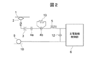
図1及び図2に示すように、実施形態1に係る鉄道車両用駆動システム100は、主回路電流が架線1から集電装置2を介して取り込まれ、断流器箱11に入り、断流器箱11を通過した主回路電流は、フィルタリアクトル5を介して、インバータ装置6に入力される。インバータ装置6に入力された電流は、可変電圧可変周波数の3相交流に変換され、誘導電動機7を駆動し、さらに車体8、車輪9を介しレール10に流れ込み、図示しない変電所に戻る構成となっている。
As shown in FIGS. 1 and 2, in the railway
断流器箱11には、図3〜図9に示すように、高速度遮断器3、単位スイッチ・充電抵抗ユニット14及び24が収納されている。単位スイッチ・充電抵抗ユニット14及び24は、単位スイッチ4a及び4bと、充電抵抗13と、単位スイッチ4a及び4bと充電抵抗13を収納するユニットフレーム15とを有している。単位スイッチ・充電抵抗ユニット14と、単位スイッチ・充電抵抗ユニット24は、図3に示すように、車両進行方向に並設されている。
As shown in FIGS. 3 to 9, the
このように、実施形態1では、単位スイッチ4a及び4bと充電抵抗13を機能単位にユニット化した構成(実施形態1では2つのユニット:単位スイッチ・充電抵抗ユニット14及び24)となっている。ここでいう機能単位とは、例えば、単位スイッチ・充電抵抗ユニット14と、単位スイッチ・充電抵抗ユニット24とで、別々のコンデンサに充電を行う等、各々異なった機能(役割)毎にユニット化することが挙げられる。なお、実施形態1では、単位スイッチ・充電抵抗ユニット14及び24が、本発明の「鉄道車両用主回路装置」に相当する。
As described above, in the first embodiment, the
通常、高速度遮断器3は閉極状態となっている。集電装置2を架線1に接触させ、単位スイッチ4aを投入すると、容量の大きいフィルタコンデンサ12が充電抵抗13を介し充電される。充電完了後、単位スイッチ4bが投入され、車両が運転可能状態となる。図示していない主幹制御器を運転士が操作すると、その操作量に応じて、インバータ装置6内の主電動機制御部が図示していない電動機を動作させる。
Usually, the high-
なお、単位スイッチ・充電抵抗ユニット14と、単位スイッチ・充電抵抗ユニット24は同じ構成を有するので、ここでは、単位スイッチ・充電抵抗ユニット14の構成について説明する。
Since the unit switch /
ユニットフレーム15内には、単位スイッチ4a及び4bが車両進行方向に並設されており、ユニットフレーム15内の単位スイッチ4a及び4bの枕木方向の車両中央側には、3つの充電抵抗13が配設されている。
In the
ユニットフレーム15は、図8及び図9に示すように、正面視で略L字状を有している。このユニットフレーム15は、底面151と、底面151の車両中央側端部に立設された背面152と、底面151及び背面152の両側に配設された側面153及び154を有している。
As shown in FIGS. 8 and 9, the
単位スイッチ4a及び4bは、図5、図6、図8及び図9に示すように、ユニットフレーム15内に、単位スイッチ4a及び4bの制御回路つまり低圧インターフェース31側を車両側面側にし、主回路つまり高圧インターフェース32側を車両中央側にし、且つ縦向きに配置されている。
As shown in FIGS. 5, 6, 8 and 9, the unit switches 4a and 4b are arranged in the
充電抵抗13は、図5及び図7〜図9に示すように、ユニットフレーム15内の単位スイッチ4a及び4bよりも車両中央側(即ち、単位スイッチ4a及び4bの高圧インターフェース32側)に配置されている。この充電抵抗13は、高圧インターフェース30側を車両中央側にし、且つ縦向きに配置されている。
As shown in FIGS. 5 and 7 to 9, the charging
ここで、単位スイッチ4a及び4bの高圧インターフェース32の位置は、ユニット化の際、充電抵抗13の後ろに隠れてしまい、外部との結線ができなくなる。そこで、図8に示すように、導体バー33のような導電性部材を用い、高圧インターフェース32を充電抵抗13の上部まで導き、高圧インターフェース32の位置を単位スイッチ・充電抵抗ユニット14の高圧インターフェース34の位置としている。このように、外部との結線が容易な場所にインターフェースを設けることで、外部との結線が可能となる。
Here, the position of the high-
また、ユニットフレーム15は、底面151の車両側面側の端部両側37a及び37bと、背面152の上部両側36a及び36bを断流器箱11との固定位置としている。即ち、実施形態1では、ユニットフレーム15と断流器箱11との固定を対角止めとしている。この固定位置により、断流器箱11との取り付け代を背面152の上部には設けるが、下部には設ける必要がないため、ユニットフレーム15(即ち、単位スイッチ・充電抵抗ユニット14)の高さ方向の寸法を短くすることができる。よって、レール10と車体8の床下との狭い空間に収まるサイズのユニットとすることができる。なお、ユニットフレーム15と断流器箱11との固定は、ボルトやネジ等、所望の固定部材によって着脱が可能である。
Further, the
さらに、ユニットフレーム15と断流器箱11との固定を対角止めとしているため、耐振性を向上させることができる。また、ユニット単体で自立するため、断流器箱11に取り付ける際、底面151を滑らせるように断流器箱11内に挿入すればよく、取り付けが簡単である。
Furthermore, since the fixing of the
このように、単位スイッチ・充電抵抗ユニット14及び24は、断流器箱11内に配設される全ての単位スイッチ4a及び4bと充電抵抗13を1つのユニットとせず、所望の機能単位に分けてユニット化したため、単位スイッチ4a及び4bの主回路配線結線作業スペースに充電抵抗13を配置可能であり、断流器箱11の小型化を図ることができる。また、単位スイッチ4a及び4bの制御回路配線結線作業を断流器箱11の外で行うため、制御回路配線の結線を行う子ネジ類の扱いが容易となる。さらにまた、単位スイッチ4a及び4bの高圧インターフェース32側と充電抵抗13を車両中央側に配置することで、断流器箱11の高圧インターフェース40の近くに高圧配線を集め、主回路配線長を短くすることができる。また、単位スイッチ4a及び4bを構成する部品交換時にも低圧インターフェース31側の結線作業スペースを従来と同様に設けているため、従来と同様に車両側面側から行うことが可能である。
In this way, the unit switch / charging
さらにまた、所望の機能単位に分けてユニット化することで、1ユニットの質量が軽くなり、製造時や点検時に断流器箱11内へのユニットの着脱が容易となる。また、電気品が故障した際には、その電気品を含むユニットだけを断流器箱11から取り外し、電気品を交換すればよく、全ての単位スイッチ4a及び4bと充電抵抗13を1ユニットとした場合と比較して、着脱の手間がかからない。
Furthermore, by dividing the unit into desired functional units, the mass of one unit is reduced, and the unit can be easily attached to and detached from the
また、単位スイッチ・充電抵抗ユニット14及び24は、図4に示すように、外部との主回路のインターフェースを最小の2点とすることが可能である。さらに、単位スイッチ・充電抵抗ユニット14及び24は、ユニットフレーム15を固定する固定部材とインターフェース2点を着脱すれば断流器箱11から簡単に着脱することができる。
Further, as shown in FIG. 4, the unit switch / charging
さらにまた、ユニット化における効果として、外段取り化による作業性の向上、作業並列化による生産性向上、案件流用による設計時間短縮を挙げることができる。 Furthermore, as an effect of unitization, workability improvement by external setup, productivity improvement by work parallelization, and design time reduction by project diversion can be mentioned.
なお、従来(図12及び図13参照)のように、断流器箱11内に、充電抵抗13を単位スイッチ4の車両進行方向側に並設すると、断流器箱11の車両進行方向の寸法が大きくなることに加え、単位スイッチ4間に絶縁距離以上に隙間が空き、さらに断流器箱11のサイズが大きくなる要因になる。
If the charging
そこで、実施形態1のように、充電抵抗13を立てて配置すれば、より高密度に電気品を収納することができ、車両進行方向の寸法を縮小することができる。この時、断流器箱11がレール10と車体8の床下との狭い空間に収まること、充電抵抗13がユニットフレーム15に取り付け可能なこと、単位スイッチ・充電抵抗ユニット14及び24が断流器箱11へ着脱可能なこと、車両進行方向の寸法を最小化すること、鉄道車両に取り付ける用品に要求される耐振性を有すること、単位スイッチ・充電抵抗ユニット14及び24単体で自立すること等が要求されるが、単位スイッチ・充電抵抗ユニット14及び24は、これらの要求を満たすことができる。
Thus, as in the first embodiment, if the charging
なお、実施形態1では、2つの単位スイッチ・充電抵抗ユニット14及び24を配設した場合について説明したが、これに限らず、ユニット数は、所望により適宜決定することができる。また、1つのユニットにおける充電抵抗13の配設数は、所望により適宜決定することができる。
In the first embodiment, the case where the two unit switches /
(実施形態2)
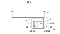
次に、本発明の実施形態2について図面を参照して説明する。図10は、実施形態2に係るインバータ装置の内部構成を模式的に示す平面図、図11は、実施形態2に係るインバータ装置を鉄道車両の車体の床下に懸架した状態を模式的に示す図である。なお、実施形態2では、実施形態1で説明した部材と同様の部材には、同一の符号を付し、その詳細な説明は省略する。
(Embodiment 2)
Next,
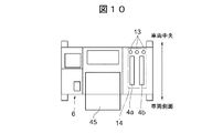
図10及び図11に示すように、実施形態2に係る鉄道車両用駆動システムと、実施形態1に係る鉄道車両用駆動システムとの異なる主な点は、単位スイッチ・充電抵抗ユニット14をインバータ装置6に配設し、このインバータ装置6を車両の車体8の床下に配設した点である。
As shown in FIGS. 10 and 11, the main difference between the railway vehicle drive system according to the second embodiment and the railway vehicle drive system according to the first embodiment is that the unit switch /
図10及び図11に示すように、実施形態2に係るインバータ装置6に配設された単位スイッチ・充電抵抗ユニット14は、インバータ装置6の高圧インターフェース50側(車両中央側)に、単位スイッチ4a及び4bの高圧インターフェース32側を位置させ、且つ縦向きに配置されている。また、充電抵抗13は、単位スイッチ4a及び4bの高圧インターフェース32側に配置されている。なお、符号45は、冷却器である。
As shown in FIGS. 10 and 11, the unit switch / charging
単位スイッチ4a及び4bの高圧インターフェース32の位置は、実施形態1と同様に、導体バー33(実施形態2では図示せず)のような導電性部材を用い、高圧インターフェース32を充電抵抗13の上部まで導き、高圧インターフェース32の位置を単位スイッチ・充電抵抗ユニット14の高圧インターフェース34の位置としている。このように、外部との結線が容易な場所にインターフェースを設けることで、単位スイッチ・充電抵抗ユニット14をインバータ装置6内に配設する場合も、外部との結線が可能となる。
The position of the high-
また、単位スイッチ・充電抵抗ユニット14は、実施形態1と同様に、インバータ装置6の筐体にユニットフレーム15を固定することで、インバータ装置6の所定位置に着脱可能に固定されている。
Similarly to the first embodiment, the unit switch / charging
このように、単位スイッチ・充電抵抗ユニット14をインバータ装置6内に配設した場合も、実施形態1と同様の要求を満たすことができ、組立結線作業が可能であると共に、小型化を達成することができる等、同様の効果を得ることができる。
As described above, even when the unit switch / charging
なお、実施形態2では、インバータ装置6に単位スイッチ・充電抵抗ユニット14を配設した場合について説明したが、これに限らず、インバータ装置6には、単位スイッチ・充電抵抗ユニット14及び24等、複数のユニットを配設することもできる。
In the second embodiment, the case where the unit switch /
また、本発明に係る鉄道車両用主回路装置は、所望により、断流器箱11やインバータ装置6以外の機器類にも適用することができる。
Moreover, the railway vehicle main circuit device according to the present invention can be applied to devices other than the
1…架線、2…集電装置、3…高速度遮断器、4a、4b…単位スイッチ、5…フィルタリアクトル、6…インバータ装置、7…誘導電動機、8…車体、9…車輪、10…レール、11…断流器箱、12…フィルタコンデンサ、13…充電抵抗、14、24…単位スイッチ・充電抵抗ユニット、15…ユニットフレーム、30、32、34、40、50…高圧インターフェース、31…低圧インターフェース、33…導体バー、36a、36b…背面の上部両側、37a、37b…車両側面側の端部両側、45…冷却器、100…鉄道車両用駆動システム、151…底面、152…背面、153…側面
DESCRIPTION OF SYMBOLS 1 ... Overhead wire, 2 ... Current collector, 3 ... High speed circuit breaker, 4a, 4b ... Unit switch, 5 ... Filter reactor, 6 ... Inverter device, 7 ... Induction motor, 8 ... Car body, 9 ... Wheel, 10 ... Rail DESCRIPTION OF
Claims (5)
複数のユニットフレームを備え、
複数のユニットフレームの夫々には、単位スイッチと充電抵抗とを備えるユニットを収容し、
前記単位スイッチは、前記鉄道車両の側面側となる位置に縦向きに配設され、前記充電抵抗は、前記単位スイッチの鉄道車両の中央側の背面に縦向きに配設されてなり、
前記単位スイッチの低圧インターフェース側が前記鉄道車両の側面側に位置し、高圧インターフェース側が前記鉄道車両の中央側に位置し、前記単位スイッチの前記充電抵抗によって隠れてしまう高圧インターフェースに導電性部材を接続し、当該導電性部材を前記充電抵抗の上部まで導くように構成されている、
鉄道車両用主回路装置。 A main circuit device for a railway vehicle disposed in a railway vehicle,
With multiple unit frames ,
Each of the plurality of unit frames accommodates a unit including a unit switch and a charging resistor ,
The unit switches is disposed vertically to the position where the side surface side of the railway vehicle, the charging resistance, Ri Na is arranged vertically on the back of the center side of the railway vehicle of the unit switch,
The low-voltage interface side of the unit switch is located on the side of the railway vehicle, the high-voltage interface side is located on the central side of the railway vehicle, and a conductive member is connected to the high-voltage interface that is hidden by the charging resistance of the unit switch. , Configured to guide the conductive member to the top of the charging resistance ,
Main circuit device for railway vehicles.
前記ユニットフレームは、当該ユニットフレーム下部の前記鉄道車両の側面側両側と、前記鉄道車両の中央側上部両側が、前記断流器の筐体に着脱可能に固定されてなる請求項1記載の鉄道車両用主回路装置。 The unit frame in which the unit switch and the charging resistor are housed is arranged in a housing of the current breaker,
2. The railway according to claim 1, wherein the unit frame is detachably fixed to both sides of the railcar at the side of the railcar and the upper side of the center of the railcar at the lower part of the unit frame. Main circuit device for vehicles.
Priority Applications (4)
| Application Number | Priority Date | Filing Date | Title |
|---|---|---|---|
| JP2015137315A JP6435239B2 (en) | 2015-07-08 | 2015-07-08 | Main circuit equipment for railway vehicles |
| GB1609841.0A GB2541086B (en) | 2015-07-08 | 2016-06-06 | Railway vehicle main circuit device |
| CN201610451972.1A CN106335375B (en) | 2015-07-08 | 2016-06-21 | Rail truck main circuit apparatus |
| DE102016212265.7A DE102016212265B4 (en) | 2015-07-08 | 2016-07-05 | Railway vehicle main circuit device |
Applications Claiming Priority (1)
| Application Number | Priority Date | Filing Date | Title |
|---|---|---|---|
| JP2015137315A JP6435239B2 (en) | 2015-07-08 | 2015-07-08 | Main circuit equipment for railway vehicles |
Publications (2)
| Publication Number | Publication Date |
|---|---|
| JP2017022834A JP2017022834A (en) | 2017-01-26 |
| JP6435239B2 true JP6435239B2 (en) | 2018-12-05 |
Family
ID=56508120
Family Applications (1)
| Application Number | Title | Priority Date | Filing Date |
|---|---|---|---|
| JP2015137315A Active JP6435239B2 (en) | 2015-07-08 | 2015-07-08 | Main circuit equipment for railway vehicles |
Country Status (4)
| Country | Link |
|---|---|
| JP (1) | JP6435239B2 (en) |
| CN (1) | CN106335375B (en) |
| DE (1) | DE102016212265B4 (en) |
| GB (1) | GB2541086B (en) |
Family Cites Families (12)
| Publication number | Priority date | Publication date | Assignee | Title |
|---|---|---|---|---|
| JPS51115458U (en) * | 1975-03-12 | 1976-09-18 | ||
| JPS59117401A (en) * | 1982-12-21 | 1984-07-06 | Toyo Electric Mfg Co Ltd | Power converter for vehicle |
| JPH02249755A (en) * | 1989-03-24 | 1990-10-05 | Hitachi Ltd | Control device for rolling stock |
| JP2512187B2 (en) | 1990-02-28 | 1996-07-03 | 株式会社日立製作所 | Vehicle disconnector |
| JPH09130074A (en) * | 1995-10-27 | 1997-05-16 | Hitachi Ltd | Cooling equipment for electrical equipment |
| JPH11215605A (en) * | 1998-01-27 | 1999-08-06 | Mitsubishi Electric Corp | Vehicle control device |
| JP2004236420A (en) * | 2003-01-30 | 2004-08-19 | Toshiba Corp | Vehicle power converter |
| WO2007138645A1 (en) * | 2006-05-25 | 2007-12-06 | Mitsubishi Electric Corporation | Auxiliary power source device for vehicle |
| CN102005989B (en) * | 2010-10-14 | 2012-09-05 | 中国北车股份有限公司大连电力牵引研发中心 | Suspension controller of magnetic suspension train |
| CN103138184B (en) * | 2011-12-01 | 2015-09-16 | 永济新时速电机电器有限责任公司 | locomotive converter cabinet |
| CN204669201U (en) * | 2015-05-13 | 2015-09-23 | 北车大连电力牵引研发中心有限公司 | Light rail vehicle traction convertor cabinet |
| DE202015103197U1 (en) * | 2015-06-17 | 2015-06-29 | Abb Technology Ag | traction |
-
2015
- 2015-07-08 JP JP2015137315A patent/JP6435239B2/en active Active
-
2016
- 2016-06-06 GB GB1609841.0A patent/GB2541086B/en active Active
- 2016-06-21 CN CN201610451972.1A patent/CN106335375B/en active Active
- 2016-07-05 DE DE102016212265.7A patent/DE102016212265B4/en active Active
Also Published As
| Publication number | Publication date |
|---|---|
| JP2017022834A (en) | 2017-01-26 |
| DE102016212265B4 (en) | 2022-03-24 |
| CN106335375A (en) | 2017-01-18 |
| GB2541086B (en) | 2018-12-12 |
| CN106335375B (en) | 2018-09-14 |
| GB201609841D0 (en) | 2016-07-20 |
| DE102016212265A1 (en) | 2017-01-12 |
| GB2541086A (en) | 2017-02-08 |
Similar Documents
| Publication | Publication Date | Title |
|---|---|---|
| CA2739935C (en) | Vehicle control device | |
| JP6193405B2 (en) | Filter device | |
| CN101454172B (en) | Control device for vehicle | |
| JP2006262665A (en) | Inverter unit for vehicle | |
| US10660229B2 (en) | Electrical device and manufacturing method of the same | |
| CN106329955B (en) | High integration metro traction chopped power module | |
| US8493731B2 (en) | Forced-air-cooled vehicle control device | |
| JP5549120B2 (en) | Power conversion device for railway vehicles | |
| CN105121229A (en) | Contactless power-supply device | |
| JP4923072B2 (en) | Commutation type DC circuit breaker | |
| CN201626319U (en) | a traction converter | |
| CN109878442B (en) | Power box, on-vehicle power system and vehicle | |
| CN106533201A (en) | Novel metro permanent magnet traction inverter | |
| JP6435239B2 (en) | Main circuit equipment for railway vehicles | |
| CN104795738A (en) | Adjustable switch cabinet easy to fix | |
| CN104242538A (en) | Motor terminal box mounted under locomotive | |
| CN205044675U (en) | High-voltage electrical appliance support for electric automobile | |
| KR102277475B1 (en) | Power control unit module for vehicle | |
| CN205588967U (en) | Hybrid vehicle battery package subassembly mounting structure and car | |
| JP5562213B2 (en) | Electrical equipment storage box | |
| CN205211814U (en) | A layer -stepping electrical apparatus box, power battery package and electric vehicle for power battery package | |
| CN210007131U (en) | electric appliance cabinet of high-speed motor train unit | |
| JP6479417B2 (en) | Electric vehicle control device | |
| JP4908604B2 (en) | Vehicle control device | |
| CN107785780A (en) | Power entry module |
Legal Events
| Date | Code | Title | Description |
|---|---|---|---|
| A621 | Written request for application examination |
Free format text: JAPANESE INTERMEDIATE CODE: A621 Effective date: 20170808 |
|
| A977 | Report on retrieval |
Free format text: JAPANESE INTERMEDIATE CODE: A971007 Effective date: 20180411 |
|
| A131 | Notification of reasons for refusal |
Free format text: JAPANESE INTERMEDIATE CODE: A131 Effective date: 20180417 |
|
| A521 | Written amendment |
Free format text: JAPANESE INTERMEDIATE CODE: A523 Effective date: 20180613 |
|
| TRDD | Decision of grant or rejection written | ||
| A01 | Written decision to grant a patent or to grant a registration (utility model) |
Free format text: JAPANESE INTERMEDIATE CODE: A01 Effective date: 20181106 |
|
| A61 | First payment of annual fees (during grant procedure) |
Free format text: JAPANESE INTERMEDIATE CODE: A61 Effective date: 20181112 |
|
| R150 | Certificate of patent or registration of utility model |
Ref document number: 6435239 Country of ref document: JP Free format text: JAPANESE INTERMEDIATE CODE: R150 |