JP6432364B2 - Manufacturing method of bonded structure - Google Patents
Manufacturing method of bonded structure Download PDFInfo
- Publication number
- JP6432364B2 JP6432364B2 JP2015008700A JP2015008700A JP6432364B2 JP 6432364 B2 JP6432364 B2 JP 6432364B2 JP 2015008700 A JP2015008700 A JP 2015008700A JP 2015008700 A JP2015008700 A JP 2015008700A JP 6432364 B2 JP6432364 B2 JP 6432364B2
- Authority
- JP
- Japan
- Prior art keywords
- laser
- manufacturing
- pressing engagement
- joining
- region
- Prior art date
- Legal status (The legal status is an assumption and is not a legal conclusion. Google has not performed a legal analysis and makes no representation as to the accuracy of the status listed.)
- Active
Links
- 238000004519 manufacturing process Methods 0.000 title claims description 43
- 238000003825 pressing Methods 0.000 claims description 81
- 238000005304 joining Methods 0.000 claims description 62
- 238000000034 method Methods 0.000 claims description 57
- 229920005989 resin Polymers 0.000 claims description 39
- 239000011347 resin Substances 0.000 claims description 39
- 229920005992 thermoplastic resin Polymers 0.000 claims description 19
- 229910052751 metal Inorganic materials 0.000 claims description 17
- 239000002184 metal Substances 0.000 claims description 17
- 230000001678 irradiating effect Effects 0.000 claims description 15
- 230000002093 peripheral effect Effects 0.000 claims description 15
- 229920001187 thermosetting polymer Polymers 0.000 claims description 15
- 230000010355 oscillation Effects 0.000 description 17
- 239000004926 polymethyl methacrylate Substances 0.000 description 16
- 229920003229 poly(methyl methacrylate) Polymers 0.000 description 14
- 238000012360 testing method Methods 0.000 description 14
- 230000015572 biosynthetic process Effects 0.000 description 11
- 239000000835 fiber Substances 0.000 description 11
- 238000012545 processing Methods 0.000 description 11
- 230000000052 comparative effect Effects 0.000 description 10
- 229920001707 polybutylene terephthalate Polymers 0.000 description 9
- 230000000694 effects Effects 0.000 description 7
- 239000004065 semiconductor Substances 0.000 description 7
- 230000007423 decrease Effects 0.000 description 6
- -1 polyethylene Polymers 0.000 description 6
- VZSRBBMJRBPUNF-UHFFFAOYSA-N 2-(2,3-dihydro-1H-inden-2-ylamino)-N-[3-oxo-3-(2,4,6,7-tetrahydrotriazolo[4,5-c]pyridin-5-yl)propyl]pyrimidine-5-carboxamide Chemical compound C1C(CC2=CC=CC=C12)NC1=NC=C(C=N1)C(=O)NCCC(N1CC2=C(CC1)NN=N2)=O VZSRBBMJRBPUNF-UHFFFAOYSA-N 0.000 description 4
- YLZOPXRUQYQQID-UHFFFAOYSA-N 3-(2,4,6,7-tetrahydrotriazolo[4,5-c]pyridin-5-yl)-1-[4-[2-[[3-(trifluoromethoxy)phenyl]methylamino]pyrimidin-5-yl]piperazin-1-yl]propan-1-one Chemical compound N1N=NC=2CN(CCC=21)CCC(=O)N1CCN(CC1)C=1C=NC(=NC=1)NCC1=CC(=CC=C1)OC(F)(F)F YLZOPXRUQYQQID-UHFFFAOYSA-N 0.000 description 4
- CURLTUGMZLYLDI-UHFFFAOYSA-N Carbon dioxide Chemical compound O=C=O CURLTUGMZLYLDI-UHFFFAOYSA-N 0.000 description 4
- AFCARXCZXQIEQB-UHFFFAOYSA-N N-[3-oxo-3-(2,4,6,7-tetrahydrotriazolo[4,5-c]pyridin-5-yl)propyl]-2-[[3-(trifluoromethoxy)phenyl]methylamino]pyrimidine-5-carboxamide Chemical compound O=C(CCNC(=O)C=1C=NC(=NC=1)NCC1=CC(=CC=C1)OC(F)(F)F)N1CC2=C(CC1)NN=N2 AFCARXCZXQIEQB-UHFFFAOYSA-N 0.000 description 4
- 238000006243 chemical reaction Methods 0.000 description 4
- 238000011156 evaluation Methods 0.000 description 4
- 239000003550 marker Substances 0.000 description 4
- 239000000463 material Substances 0.000 description 4
- 238000012986 modification Methods 0.000 description 4
- 230000004048 modification Effects 0.000 description 4
- 238000010586 diagram Methods 0.000 description 3
- 239000000945 filler Substances 0.000 description 3
- 229920002725 thermoplastic elastomer Polymers 0.000 description 3
- 229920006353 Acrylite® Polymers 0.000 description 2
- 229920002430 Fibre-reinforced plastic Polymers 0.000 description 2
- 229920000106 Liquid crystal polymer Polymers 0.000 description 2
- 239000004977 Liquid-crystal polymers (LCPs) Substances 0.000 description 2
- 229920000877 Melamine resin Polymers 0.000 description 2
- 229920002292 Nylon 6 Polymers 0.000 description 2
- 229920002302 Nylon 6,6 Polymers 0.000 description 2
- 239000004696 Poly ether ether ketone Substances 0.000 description 2
- 239000004695 Polyether sulfone Substances 0.000 description 2
- 239000004697 Polyetherimide Substances 0.000 description 2
- 239000004698 Polyethylene Substances 0.000 description 2
- 239000004734 Polyphenylene sulfide Substances 0.000 description 2
- 239000004743 Polypropylene Substances 0.000 description 2
- 239000004793 Polystyrene Substances 0.000 description 2
- 229920001328 Polyvinylidene chloride Polymers 0.000 description 2
- 229920000297 Rayon Polymers 0.000 description 2
- PPBRXRYQALVLMV-UHFFFAOYSA-N Styrene Chemical compound C=CC1=CC=CC=C1 PPBRXRYQALVLMV-UHFFFAOYSA-N 0.000 description 2
- 229920001807 Urea-formaldehyde Polymers 0.000 description 2
- 238000010521 absorption reaction Methods 0.000 description 2
- XECAHXYUAAWDEL-UHFFFAOYSA-N acrylonitrile butadiene styrene Chemical compound C=CC=C.C=CC#N.C=CC1=CC=CC=C1 XECAHXYUAAWDEL-UHFFFAOYSA-N 0.000 description 2
- 239000004676 acrylonitrile butadiene styrene Substances 0.000 description 2
- 229920000122 acrylonitrile butadiene styrene Polymers 0.000 description 2
- 229920001893 acrylonitrile styrene Polymers 0.000 description 2
- XAGFODPZIPBFFR-UHFFFAOYSA-N aluminium Chemical compound [Al] XAGFODPZIPBFFR-UHFFFAOYSA-N 0.000 description 2
- 230000005540 biological transmission Effects 0.000 description 2
- 239000001569 carbon dioxide Substances 0.000 description 2
- 229910002092 carbon dioxide Inorganic materials 0.000 description 2
- 238000005520 cutting process Methods 0.000 description 2
- 238000004512 die casting Methods 0.000 description 2
- 230000005489 elastic deformation Effects 0.000 description 2
- 239000011151 fibre-reinforced plastic Substances 0.000 description 2
- IVJISJACKSSFGE-UHFFFAOYSA-N formaldehyde;1,3,5-triazine-2,4,6-triamine Chemical compound O=C.NC1=NC(N)=NC(N)=N1 IVJISJACKSSFGE-UHFFFAOYSA-N 0.000 description 2
- SLGWESQGEUXWJQ-UHFFFAOYSA-N formaldehyde;phenol Chemical compound O=C.OC1=CC=CC=C1 SLGWESQGEUXWJQ-UHFFFAOYSA-N 0.000 description 2
- 238000002844 melting Methods 0.000 description 2
- 230000008018 melting Effects 0.000 description 2
- 239000000203 mixture Substances 0.000 description 2
- 238000000465 moulding Methods 0.000 description 2
- 229920001568 phenolic resin Polymers 0.000 description 2
- 229920002493 poly(chlorotrifluoroethylene) Polymers 0.000 description 2
- 229920002492 poly(sulfone) Polymers 0.000 description 2
- 229920001230 polyarylate Polymers 0.000 description 2
- 239000004417 polycarbonate Substances 0.000 description 2
- 239000005023 polychlorotrifluoroethylene (PCTFE) polymer Substances 0.000 description 2
- 229920006393 polyether sulfone Polymers 0.000 description 2
- 229920002530 polyetherether ketone Polymers 0.000 description 2
- 229920001601 polyetherimide Polymers 0.000 description 2
- 229920000139 polyethylene terephthalate Polymers 0.000 description 2
- 239000005020 polyethylene terephthalate Substances 0.000 description 2
- 229920000642 polymer Polymers 0.000 description 2
- ODGAOXROABLFNM-UHFFFAOYSA-N polynoxylin Chemical compound O=C.NC(N)=O ODGAOXROABLFNM-UHFFFAOYSA-N 0.000 description 2
- 229920006324 polyoxymethylene Polymers 0.000 description 2
- 229920000069 polyphenylene sulfide Polymers 0.000 description 2
- 229920001343 polytetrafluoroethylene Polymers 0.000 description 2
- 239000004810 polytetrafluoroethylene Substances 0.000 description 2
- 229920002635 polyurethane Polymers 0.000 description 2
- 239000004814 polyurethane Substances 0.000 description 2
- 239000004800 polyvinyl chloride Substances 0.000 description 2
- 229920000915 polyvinyl chloride Polymers 0.000 description 2
- 239000005033 polyvinylidene chloride Substances 0.000 description 2
- 229920002981 polyvinylidene fluoride Polymers 0.000 description 2
- SCUZVMOVTVSBLE-UHFFFAOYSA-N prop-2-enenitrile;styrene Chemical compound C=CC#N.C=CC1=CC=CC=C1 SCUZVMOVTVSBLE-UHFFFAOYSA-N 0.000 description 2
- 239000002964 rayon Substances 0.000 description 2
- 238000010008 shearing Methods 0.000 description 2
- 229920006305 unsaturated polyester Polymers 0.000 description 2
- 229920000049 Carbon (fiber) Polymers 0.000 description 1
- RYGMFSIKBFXOCR-UHFFFAOYSA-N Copper Chemical compound [Cu] RYGMFSIKBFXOCR-UHFFFAOYSA-N 0.000 description 1
- 239000004593 Epoxy Substances 0.000 description 1
- JOYRKODLDBILNP-UHFFFAOYSA-N Ethyl urethane Chemical compound CCOC(N)=O JOYRKODLDBILNP-UHFFFAOYSA-N 0.000 description 1
- XEEYBQQBJWHFJM-UHFFFAOYSA-N Iron Chemical compound [Fe] XEEYBQQBJWHFJM-UHFFFAOYSA-N 0.000 description 1
- FYYHWMGAXLPEAU-UHFFFAOYSA-N Magnesium Chemical compound [Mg] FYYHWMGAXLPEAU-UHFFFAOYSA-N 0.000 description 1
- 239000004677 Nylon Substances 0.000 description 1
- 239000002033 PVDF binder Substances 0.000 description 1
- 229930182556 Polyacetal Natural products 0.000 description 1
- BZHJMEDXRYGGRV-UHFFFAOYSA-N Vinyl chloride Chemical compound ClC=C BZHJMEDXRYGGRV-UHFFFAOYSA-N 0.000 description 1
- HCHKCACWOHOZIP-UHFFFAOYSA-N Zinc Chemical compound [Zn] HCHKCACWOHOZIP-UHFFFAOYSA-N 0.000 description 1
- 230000001154 acute effect Effects 0.000 description 1
- 150000001336 alkenes Chemical class 0.000 description 1
- 239000000956 alloy Substances 0.000 description 1
- 229910045601 alloy Inorganic materials 0.000 description 1
- 229910052782 aluminium Inorganic materials 0.000 description 1
- 238000007743 anodising Methods 0.000 description 1
- 239000004917 carbon fiber Substances 0.000 description 1
- 229910052802 copper Inorganic materials 0.000 description 1
- 239000010949 copper Substances 0.000 description 1
- 238000009826 distribution Methods 0.000 description 1
- 150000002148 esters Chemical class 0.000 description 1
- 238000005530 etching Methods 0.000 description 1
- 239000003365 glass fiber Substances 0.000 description 1
- 230000012447 hatching Effects 0.000 description 1
- 238000010438 heat treatment Methods 0.000 description 1
- 239000011256 inorganic filler Substances 0.000 description 1
- 229910003475 inorganic filler Inorganic materials 0.000 description 1
- 238000003780 insertion Methods 0.000 description 1
- 230000037431 insertion Effects 0.000 description 1
- 229920001778 nylon Polymers 0.000 description 1
- JRZJOMJEPLMPRA-UHFFFAOYSA-N olefin Natural products CCCCCCCC=C JRZJOMJEPLMPRA-UHFFFAOYSA-N 0.000 description 1
- 239000012766 organic filler Substances 0.000 description 1
- 229920000515 polycarbonate Polymers 0.000 description 1
- 229920000573 polyethylene Polymers 0.000 description 1
- 229920001955 polyphenylene ether Polymers 0.000 description 1
- 229920001155 polypropylene Polymers 0.000 description 1
- 229920001296 polysiloxane Polymers 0.000 description 1
- 229920002223 polystyrene Polymers 0.000 description 1
- 238000004663 powder metallurgy Methods 0.000 description 1
- 150000003839 salts Chemical class 0.000 description 1
- 229910001220 stainless steel Inorganic materials 0.000 description 1
- 239000010935 stainless steel Substances 0.000 description 1
- 229920006346 thermoplastic polyester elastomer Polymers 0.000 description 1
- 238000002834 transmittance Methods 0.000 description 1
- 238000003466 welding Methods 0.000 description 1
- 239000011701 zinc Substances 0.000 description 1
- 229910052725 zinc Inorganic materials 0.000 description 1
Images


Classifications
-
- B—PERFORMING OPERATIONS; TRANSPORTING
- B23—MACHINE TOOLS; METAL-WORKING NOT OTHERWISE PROVIDED FOR
- B23K—SOLDERING OR UNSOLDERING; WELDING; CLADDING OR PLATING BY SOLDERING OR WELDING; CUTTING BY APPLYING HEAT LOCALLY, e.g. FLAME CUTTING; WORKING BY LASER BEAM
- B23K26/00—Working by laser beam, e.g. welding, cutting or boring
- B23K26/20—Bonding
- B23K26/32—Bonding taking account of the properties of the material involved
- B23K26/324—Bonding taking account of the properties of the material involved involving non-metallic parts
-
- B—PERFORMING OPERATIONS; TRANSPORTING
- B29—WORKING OF PLASTICS; WORKING OF SUBSTANCES IN A PLASTIC STATE IN GENERAL
- B29C—SHAPING OR JOINING OF PLASTICS; SHAPING OF MATERIAL IN A PLASTIC STATE, NOT OTHERWISE PROVIDED FOR; AFTER-TREATMENT OF THE SHAPED PRODUCTS, e.g. REPAIRING
- B29C65/00—Joining or sealing of preformed parts, e.g. welding of plastics materials; Apparatus therefor
- B29C65/02—Joining or sealing of preformed parts, e.g. welding of plastics materials; Apparatus therefor by heating, with or without pressure
- B29C65/14—Joining or sealing of preformed parts, e.g. welding of plastics materials; Apparatus therefor by heating, with or without pressure using wave energy, i.e. electromagnetic radiation, or particle radiation
- B29C65/16—Laser beams
- B29C65/1603—Laser beams characterised by the type of electromagnetic radiation
- B29C65/1612—Infrared [IR] radiation, e.g. by infrared lasers
- B29C65/1616—Near infrared radiation [NIR], e.g. by YAG lasers
-
- B—PERFORMING OPERATIONS; TRANSPORTING
- B23—MACHINE TOOLS; METAL-WORKING NOT OTHERWISE PROVIDED FOR
- B23K—SOLDERING OR UNSOLDERING; WELDING; CLADDING OR PLATING BY SOLDERING OR WELDING; CUTTING BY APPLYING HEAT LOCALLY, e.g. FLAME CUTTING; WORKING BY LASER BEAM
- B23K26/00—Working by laser beam, e.g. welding, cutting or boring
- B23K26/352—Working by laser beam, e.g. welding, cutting or boring for surface treatment
- B23K26/354—Working by laser beam, e.g. welding, cutting or boring for surface treatment by melting
-
- B—PERFORMING OPERATIONS; TRANSPORTING
- B29—WORKING OF PLASTICS; WORKING OF SUBSTANCES IN A PLASTIC STATE IN GENERAL
- B29C—SHAPING OR JOINING OF PLASTICS; SHAPING OF MATERIAL IN A PLASTIC STATE, NOT OTHERWISE PROVIDED FOR; AFTER-TREATMENT OF THE SHAPED PRODUCTS, e.g. REPAIRING
- B29C65/00—Joining or sealing of preformed parts, e.g. welding of plastics materials; Apparatus therefor
- B29C65/02—Joining or sealing of preformed parts, e.g. welding of plastics materials; Apparatus therefor by heating, with or without pressure
- B29C65/14—Joining or sealing of preformed parts, e.g. welding of plastics materials; Apparatus therefor by heating, with or without pressure using wave energy, i.e. electromagnetic radiation, or particle radiation
- B29C65/16—Laser beams
- B29C65/1629—Laser beams characterised by the way of heating the interface
- B29C65/1635—Laser beams characterised by the way of heating the interface at least passing through one of the parts to be joined, i.e. laser transmission welding
-
- B—PERFORMING OPERATIONS; TRANSPORTING
- B29—WORKING OF PLASTICS; WORKING OF SUBSTANCES IN A PLASTIC STATE IN GENERAL
- B29C—SHAPING OR JOINING OF PLASTICS; SHAPING OF MATERIAL IN A PLASTIC STATE, NOT OTHERWISE PROVIDED FOR; AFTER-TREATMENT OF THE SHAPED PRODUCTS, e.g. REPAIRING
- B29C65/00—Joining or sealing of preformed parts, e.g. welding of plastics materials; Apparatus therefor
- B29C65/56—Joining or sealing of preformed parts, e.g. welding of plastics materials; Apparatus therefor using mechanical means or mechanical connections, e.g. form-fits
- B29C65/58—Snap connection
-
- B—PERFORMING OPERATIONS; TRANSPORTING
- B29—WORKING OF PLASTICS; WORKING OF SUBSTANCES IN A PLASTIC STATE IN GENERAL
- B29C—SHAPING OR JOINING OF PLASTICS; SHAPING OF MATERIAL IN A PLASTIC STATE, NOT OTHERWISE PROVIDED FOR; AFTER-TREATMENT OF THE SHAPED PRODUCTS, e.g. REPAIRING
- B29C65/00—Joining or sealing of preformed parts, e.g. welding of plastics materials; Apparatus therefor
- B29C65/56—Joining or sealing of preformed parts, e.g. welding of plastics materials; Apparatus therefor using mechanical means or mechanical connections, e.g. form-fits
- B29C65/60—Riveting or staking
- B29C65/606—Riveting or staking the rivets being integral with one of the parts to be joined, i.e. staking
- B29C65/609—Riveting or staking the rivets being integral with one of the parts to be joined, i.e. staking the integral rivets being plunge-formed
-
- B—PERFORMING OPERATIONS; TRANSPORTING
- B29—WORKING OF PLASTICS; WORKING OF SUBSTANCES IN A PLASTIC STATE IN GENERAL
- B29C—SHAPING OR JOINING OF PLASTICS; SHAPING OF MATERIAL IN A PLASTIC STATE, NOT OTHERWISE PROVIDED FOR; AFTER-TREATMENT OF THE SHAPED PRODUCTS, e.g. REPAIRING
- B29C65/00—Joining or sealing of preformed parts, e.g. welding of plastics materials; Apparatus therefor
- B29C65/56—Joining or sealing of preformed parts, e.g. welding of plastics materials; Apparatus therefor using mechanical means or mechanical connections, e.g. form-fits
- B29C65/64—Joining a non-plastics element to a plastics element, e.g. by force
-
- B—PERFORMING OPERATIONS; TRANSPORTING
- B29—WORKING OF PLASTICS; WORKING OF SUBSTANCES IN A PLASTIC STATE IN GENERAL
- B29C—SHAPING OR JOINING OF PLASTICS; SHAPING OF MATERIAL IN A PLASTIC STATE, NOT OTHERWISE PROVIDED FOR; AFTER-TREATMENT OF THE SHAPED PRODUCTS, e.g. REPAIRING
- B29C66/00—General aspects of processes or apparatus for joining preformed parts
- B29C66/01—General aspects dealing with the joint area or with the area to be joined
- B29C66/02—Preparation of the material, in the area to be joined, prior to joining or welding
- B29C66/024—Thermal pre-treatments
- B29C66/0246—Cutting or perforating, e.g. burning away by using a laser or using hot air
-
- B—PERFORMING OPERATIONS; TRANSPORTING
- B29—WORKING OF PLASTICS; WORKING OF SUBSTANCES IN A PLASTIC STATE IN GENERAL
- B29C—SHAPING OR JOINING OF PLASTICS; SHAPING OF MATERIAL IN A PLASTIC STATE, NOT OTHERWISE PROVIDED FOR; AFTER-TREATMENT OF THE SHAPED PRODUCTS, e.g. REPAIRING
- B29C66/00—General aspects of processes or apparatus for joining preformed parts
- B29C66/01—General aspects dealing with the joint area or with the area to be joined
- B29C66/05—Particular design of joint configurations
- B29C66/10—Particular design of joint configurations particular design of the joint cross-sections
- B29C66/11—Joint cross-sections comprising a single joint-segment, i.e. one of the parts to be joined comprising a single joint-segment in the joint cross-section
- B29C66/112—Single lapped joints
- B29C66/1122—Single lap to lap joints, i.e. overlap joints
-
- B—PERFORMING OPERATIONS; TRANSPORTING
- B29—WORKING OF PLASTICS; WORKING OF SUBSTANCES IN A PLASTIC STATE IN GENERAL
- B29C—SHAPING OR JOINING OF PLASTICS; SHAPING OF MATERIAL IN A PLASTIC STATE, NOT OTHERWISE PROVIDED FOR; AFTER-TREATMENT OF THE SHAPED PRODUCTS, e.g. REPAIRING
- B29C66/00—General aspects of processes or apparatus for joining preformed parts
- B29C66/01—General aspects dealing with the joint area or with the area to be joined
- B29C66/05—Particular design of joint configurations
- B29C66/20—Particular design of joint configurations particular design of the joint lines, e.g. of the weld lines
- B29C66/21—Particular design of joint configurations particular design of the joint lines, e.g. of the weld lines said joint lines being formed by a single dot or dash or by several dots or dashes, i.e. spot joining or spot welding
-
- B—PERFORMING OPERATIONS; TRANSPORTING
- B29—WORKING OF PLASTICS; WORKING OF SUBSTANCES IN A PLASTIC STATE IN GENERAL
- B29C—SHAPING OR JOINING OF PLASTICS; SHAPING OF MATERIAL IN A PLASTIC STATE, NOT OTHERWISE PROVIDED FOR; AFTER-TREATMENT OF THE SHAPED PRODUCTS, e.g. REPAIRING
- B29C66/00—General aspects of processes or apparatus for joining preformed parts
- B29C66/01—General aspects dealing with the joint area or with the area to be joined
- B29C66/05—Particular design of joint configurations
- B29C66/303—Particular design of joint configurations the joint involving an anchoring effect
- B29C66/3032—Particular design of joint configurations the joint involving an anchoring effect making use of protrusions or cavities belonging to at least one of the parts to be joined
- B29C66/30325—Particular design of joint configurations the joint involving an anchoring effect making use of protrusions or cavities belonging to at least one of the parts to be joined making use of cavities belonging to at least one of the parts to be joined
-
- B—PERFORMING OPERATIONS; TRANSPORTING
- B29—WORKING OF PLASTICS; WORKING OF SUBSTANCES IN A PLASTIC STATE IN GENERAL
- B29C—SHAPING OR JOINING OF PLASTICS; SHAPING OF MATERIAL IN A PLASTIC STATE, NOT OTHERWISE PROVIDED FOR; AFTER-TREATMENT OF THE SHAPED PRODUCTS, e.g. REPAIRING
- B29C66/00—General aspects of processes or apparatus for joining preformed parts
- B29C66/01—General aspects dealing with the joint area or with the area to be joined
- B29C66/32—Measures for keeping the burr form under control; Avoiding burr formation; Shaping the burr
- B29C66/322—Providing cavities in the joined article to collect the burr
-
- B—PERFORMING OPERATIONS; TRANSPORTING
- B29—WORKING OF PLASTICS; WORKING OF SUBSTANCES IN A PLASTIC STATE IN GENERAL
- B29C—SHAPING OR JOINING OF PLASTICS; SHAPING OF MATERIAL IN A PLASTIC STATE, NOT OTHERWISE PROVIDED FOR; AFTER-TREATMENT OF THE SHAPED PRODUCTS, e.g. REPAIRING
- B29C66/00—General aspects of processes or apparatus for joining preformed parts
- B29C66/40—General aspects of joining substantially flat articles, e.g. plates, sheets or web-like materials; Making flat seams in tubular or hollow articles; Joining single elements to substantially flat surfaces
- B29C66/41—Joining substantially flat articles ; Making flat seams in tubular or hollow articles
- B29C66/43—Joining a relatively small portion of the surface of said articles
-
- B—PERFORMING OPERATIONS; TRANSPORTING
- B29—WORKING OF PLASTICS; WORKING OF SUBSTANCES IN A PLASTIC STATE IN GENERAL
- B29C—SHAPING OR JOINING OF PLASTICS; SHAPING OF MATERIAL IN A PLASTIC STATE, NOT OTHERWISE PROVIDED FOR; AFTER-TREATMENT OF THE SHAPED PRODUCTS, e.g. REPAIRING
- B29C66/00—General aspects of processes or apparatus for joining preformed parts
- B29C66/50—General aspects of joining tubular articles; General aspects of joining long products, i.e. bars or profiled elements; General aspects of joining single elements to tubular articles, hollow articles or bars; General aspects of joining several hollow-preforms to form hollow or tubular articles
- B29C66/51—Joining tubular articles, profiled elements or bars; Joining single elements to tubular articles, hollow articles or bars; Joining several hollow-preforms to form hollow or tubular articles
- B29C66/53—Joining single elements to tubular articles, hollow articles or bars
- B29C66/532—Joining single elements to the wall of tubular articles, hollow articles or bars
- B29C66/5326—Joining single elements to the wall of tubular articles, hollow articles or bars said single elements being substantially flat
-
- B—PERFORMING OPERATIONS; TRANSPORTING
- B29—WORKING OF PLASTICS; WORKING OF SUBSTANCES IN A PLASTIC STATE IN GENERAL
- B29C—SHAPING OR JOINING OF PLASTICS; SHAPING OF MATERIAL IN A PLASTIC STATE, NOT OTHERWISE PROVIDED FOR; AFTER-TREATMENT OF THE SHAPED PRODUCTS, e.g. REPAIRING
- B29C66/00—General aspects of processes or apparatus for joining preformed parts
- B29C66/50—General aspects of joining tubular articles; General aspects of joining long products, i.e. bars or profiled elements; General aspects of joining single elements to tubular articles, hollow articles or bars; General aspects of joining several hollow-preforms to form hollow or tubular articles
- B29C66/61—Joining from or joining on the inside
-
- B—PERFORMING OPERATIONS; TRANSPORTING
- B29—WORKING OF PLASTICS; WORKING OF SUBSTANCES IN A PLASTIC STATE IN GENERAL
- B29C—SHAPING OR JOINING OF PLASTICS; SHAPING OF MATERIAL IN A PLASTIC STATE, NOT OTHERWISE PROVIDED FOR; AFTER-TREATMENT OF THE SHAPED PRODUCTS, e.g. REPAIRING
- B29C66/00—General aspects of processes or apparatus for joining preformed parts
- B29C66/70—General aspects of processes or apparatus for joining preformed parts characterised by the composition, physical properties or the structure of the material of the parts to be joined; Joining with non-plastics material
- B29C66/74—Joining plastics material to non-plastics material
- B29C66/742—Joining plastics material to non-plastics material to metals or their alloys
-
- B—PERFORMING OPERATIONS; TRANSPORTING
- B29—WORKING OF PLASTICS; WORKING OF SUBSTANCES IN A PLASTIC STATE IN GENERAL
- B29C—SHAPING OR JOINING OF PLASTICS; SHAPING OF MATERIAL IN A PLASTIC STATE, NOT OTHERWISE PROVIDED FOR; AFTER-TREATMENT OF THE SHAPED PRODUCTS, e.g. REPAIRING
- B29C65/00—Joining or sealing of preformed parts, e.g. welding of plastics materials; Apparatus therefor
- B29C65/56—Joining or sealing of preformed parts, e.g. welding of plastics materials; Apparatus therefor using mechanical means or mechanical connections, e.g. form-fits
- B29C65/60—Riveting or staking
- B29C65/606—Riveting or staking the rivets being integral with one of the parts to be joined, i.e. staking
- B29C65/607—Riveting or staking the rivets being integral with one of the parts to be joined, i.e. staking the integral rivets being hollow
-
- B—PERFORMING OPERATIONS; TRANSPORTING
- B29—WORKING OF PLASTICS; WORKING OF SUBSTANCES IN A PLASTIC STATE IN GENERAL
- B29C—SHAPING OR JOINING OF PLASTICS; SHAPING OF MATERIAL IN A PLASTIC STATE, NOT OTHERWISE PROVIDED FOR; AFTER-TREATMENT OF THE SHAPED PRODUCTS, e.g. REPAIRING
- B29C66/00—General aspects of processes or apparatus for joining preformed parts
- B29C66/70—General aspects of processes or apparatus for joining preformed parts characterised by the composition, physical properties or the structure of the material of the parts to be joined; Joining with non-plastics material
- B29C66/71—General aspects of processes or apparatus for joining preformed parts characterised by the composition, physical properties or the structure of the material of the parts to be joined; Joining with non-plastics material characterised by the composition of the plastics material of the parts to be joined
- B29C66/712—General aspects of processes or apparatus for joining preformed parts characterised by the composition, physical properties or the structure of the material of the parts to be joined; Joining with non-plastics material characterised by the composition of the plastics material of the parts to be joined the composition of one of the parts to be joined being different from the composition of the other part
-
- B—PERFORMING OPERATIONS; TRANSPORTING
- B29—WORKING OF PLASTICS; WORKING OF SUBSTANCES IN A PLASTIC STATE IN GENERAL
- B29C—SHAPING OR JOINING OF PLASTICS; SHAPING OF MATERIAL IN A PLASTIC STATE, NOT OTHERWISE PROVIDED FOR; AFTER-TREATMENT OF THE SHAPED PRODUCTS, e.g. REPAIRING
- B29C66/00—General aspects of processes or apparatus for joining preformed parts
- B29C66/70—General aspects of processes or apparatus for joining preformed parts characterised by the composition, physical properties or the structure of the material of the parts to be joined; Joining with non-plastics material
- B29C66/72—General aspects of processes or apparatus for joining preformed parts characterised by the composition, physical properties or the structure of the material of the parts to be joined; Joining with non-plastics material characterised by the structure of the material of the parts to be joined
- B29C66/721—Fibre-reinforced materials
- B29C66/7212—Fibre-reinforced materials characterised by the composition of the fibres
-
- B—PERFORMING OPERATIONS; TRANSPORTING
- B29—WORKING OF PLASTICS; WORKING OF SUBSTANCES IN A PLASTIC STATE IN GENERAL
- B29C—SHAPING OR JOINING OF PLASTICS; SHAPING OF MATERIAL IN A PLASTIC STATE, NOT OTHERWISE PROVIDED FOR; AFTER-TREATMENT OF THE SHAPED PRODUCTS, e.g. REPAIRING
- B29C66/00—General aspects of processes or apparatus for joining preformed parts
- B29C66/70—General aspects of processes or apparatus for joining preformed parts characterised by the composition, physical properties or the structure of the material of the parts to be joined; Joining with non-plastics material
- B29C66/73—General aspects of processes or apparatus for joining preformed parts characterised by the composition, physical properties or the structure of the material of the parts to be joined; Joining with non-plastics material characterised by the intensive physical properties of the material of the parts to be joined, by the optical properties of the material of the parts to be joined, by the extensive physical properties of the parts to be joined, by the state of the material of the parts to be joined or by the material of the parts to be joined being a thermoplastic or a thermoset
- B29C66/739—General aspects of processes or apparatus for joining preformed parts characterised by the composition, physical properties or the structure of the material of the parts to be joined; Joining with non-plastics material characterised by the intensive physical properties of the material of the parts to be joined, by the optical properties of the material of the parts to be joined, by the extensive physical properties of the parts to be joined, by the state of the material of the parts to be joined or by the material of the parts to be joined being a thermoplastic or a thermoset characterised by the material of the parts to be joined being a thermoplastic or a thermoset
- B29C66/7392—General aspects of processes or apparatus for joining preformed parts characterised by the composition, physical properties or the structure of the material of the parts to be joined; Joining with non-plastics material characterised by the intensive physical properties of the material of the parts to be joined, by the optical properties of the material of the parts to be joined, by the extensive physical properties of the parts to be joined, by the state of the material of the parts to be joined or by the material of the parts to be joined being a thermoplastic or a thermoset characterised by the material of the parts to be joined being a thermoplastic or a thermoset characterised by the material of at least one of the parts being a thermoplastic
- B29C66/73921—General aspects of processes or apparatus for joining preformed parts characterised by the composition, physical properties or the structure of the material of the parts to be joined; Joining with non-plastics material characterised by the intensive physical properties of the material of the parts to be joined, by the optical properties of the material of the parts to be joined, by the extensive physical properties of the parts to be joined, by the state of the material of the parts to be joined or by the material of the parts to be joined being a thermoplastic or a thermoset characterised by the material of the parts to be joined being a thermoplastic or a thermoset characterised by the material of at least one of the parts being a thermoplastic characterised by the materials of both parts being thermoplastics
-
- B—PERFORMING OPERATIONS; TRANSPORTING
- B29—WORKING OF PLASTICS; WORKING OF SUBSTANCES IN A PLASTIC STATE IN GENERAL
- B29C—SHAPING OR JOINING OF PLASTICS; SHAPING OF MATERIAL IN A PLASTIC STATE, NOT OTHERWISE PROVIDED FOR; AFTER-TREATMENT OF THE SHAPED PRODUCTS, e.g. REPAIRING
- B29C66/00—General aspects of processes or apparatus for joining preformed parts
- B29C66/70—General aspects of processes or apparatus for joining preformed parts characterised by the composition, physical properties or the structure of the material of the parts to be joined; Joining with non-plastics material
- B29C66/73—General aspects of processes or apparatus for joining preformed parts characterised by the composition, physical properties or the structure of the material of the parts to be joined; Joining with non-plastics material characterised by the intensive physical properties of the material of the parts to be joined, by the optical properties of the material of the parts to be joined, by the extensive physical properties of the parts to be joined, by the state of the material of the parts to be joined or by the material of the parts to be joined being a thermoplastic or a thermoset
- B29C66/739—General aspects of processes or apparatus for joining preformed parts characterised by the composition, physical properties or the structure of the material of the parts to be joined; Joining with non-plastics material characterised by the intensive physical properties of the material of the parts to be joined, by the optical properties of the material of the parts to be joined, by the extensive physical properties of the parts to be joined, by the state of the material of the parts to be joined or by the material of the parts to be joined being a thermoplastic or a thermoset characterised by the material of the parts to be joined being a thermoplastic or a thermoset
- B29C66/7394—General aspects of processes or apparatus for joining preformed parts characterised by the composition, physical properties or the structure of the material of the parts to be joined; Joining with non-plastics material characterised by the intensive physical properties of the material of the parts to be joined, by the optical properties of the material of the parts to be joined, by the extensive physical properties of the parts to be joined, by the state of the material of the parts to be joined or by the material of the parts to be joined being a thermoplastic or a thermoset characterised by the material of the parts to be joined being a thermoplastic or a thermoset characterised by the material of at least one of the parts being a thermoset
- B29C66/73941—General aspects of processes or apparatus for joining preformed parts characterised by the composition, physical properties or the structure of the material of the parts to be joined; Joining with non-plastics material characterised by the intensive physical properties of the material of the parts to be joined, by the optical properties of the material of the parts to be joined, by the extensive physical properties of the parts to be joined, by the state of the material of the parts to be joined or by the material of the parts to be joined being a thermoplastic or a thermoset characterised by the material of the parts to be joined being a thermoplastic or a thermoset characterised by the material of at least one of the parts being a thermoset characterised by the materials of both parts being thermosets
-
- B—PERFORMING OPERATIONS; TRANSPORTING
- B29—WORKING OF PLASTICS; WORKING OF SUBSTANCES IN A PLASTIC STATE IN GENERAL
- B29C—SHAPING OR JOINING OF PLASTICS; SHAPING OF MATERIAL IN A PLASTIC STATE, NOT OTHERWISE PROVIDED FOR; AFTER-TREATMENT OF THE SHAPED PRODUCTS, e.g. REPAIRING
- B29C66/00—General aspects of processes or apparatus for joining preformed parts
- B29C66/70—General aspects of processes or apparatus for joining preformed parts characterised by the composition, physical properties or the structure of the material of the parts to be joined; Joining with non-plastics material
- B29C66/74—Joining plastics material to non-plastics material
- B29C66/742—Joining plastics material to non-plastics material to metals or their alloys
- B29C66/7422—Aluminium or alloys of aluminium
-
- B—PERFORMING OPERATIONS; TRANSPORTING
- B29—WORKING OF PLASTICS; WORKING OF SUBSTANCES IN A PLASTIC STATE IN GENERAL
- B29C—SHAPING OR JOINING OF PLASTICS; SHAPING OF MATERIAL IN A PLASTIC STATE, NOT OTHERWISE PROVIDED FOR; AFTER-TREATMENT OF THE SHAPED PRODUCTS, e.g. REPAIRING
- B29C66/00—General aspects of processes or apparatus for joining preformed parts
- B29C66/70—General aspects of processes or apparatus for joining preformed parts characterised by the composition, physical properties or the structure of the material of the parts to be joined; Joining with non-plastics material
- B29C66/74—Joining plastics material to non-plastics material
- B29C66/742—Joining plastics material to non-plastics material to metals or their alloys
- B29C66/7428—Transition metals or their alloys
- B29C66/74281—Copper or alloys of copper
-
- B—PERFORMING OPERATIONS; TRANSPORTING
- B29—WORKING OF PLASTICS; WORKING OF SUBSTANCES IN A PLASTIC STATE IN GENERAL
- B29C—SHAPING OR JOINING OF PLASTICS; SHAPING OF MATERIAL IN A PLASTIC STATE, NOT OTHERWISE PROVIDED FOR; AFTER-TREATMENT OF THE SHAPED PRODUCTS, e.g. REPAIRING
- B29C66/00—General aspects of processes or apparatus for joining preformed parts
- B29C66/70—General aspects of processes or apparatus for joining preformed parts characterised by the composition, physical properties or the structure of the material of the parts to be joined; Joining with non-plastics material
- B29C66/74—Joining plastics material to non-plastics material
- B29C66/742—Joining plastics material to non-plastics material to metals or their alloys
- B29C66/7428—Transition metals or their alloys
- B29C66/74283—Iron or alloys of iron, e.g. steel
-
- B—PERFORMING OPERATIONS; TRANSPORTING
- B29—WORKING OF PLASTICS; WORKING OF SUBSTANCES IN A PLASTIC STATE IN GENERAL
- B29C—SHAPING OR JOINING OF PLASTICS; SHAPING OF MATERIAL IN A PLASTIC STATE, NOT OTHERWISE PROVIDED FOR; AFTER-TREATMENT OF THE SHAPED PRODUCTS, e.g. REPAIRING
- B29C66/00—General aspects of processes or apparatus for joining preformed parts
- B29C66/90—Measuring or controlling the joining process
- B29C66/91—Measuring or controlling the joining process by measuring or controlling the temperature, the heat or the thermal flux
- B29C66/919—Measuring or controlling the joining process by measuring or controlling the temperature, the heat or the thermal flux characterised by specific temperature, heat or thermal flux values or ranges
-
- B—PERFORMING OPERATIONS; TRANSPORTING
- B29—WORKING OF PLASTICS; WORKING OF SUBSTANCES IN A PLASTIC STATE IN GENERAL
- B29C—SHAPING OR JOINING OF PLASTICS; SHAPING OF MATERIAL IN A PLASTIC STATE, NOT OTHERWISE PROVIDED FOR; AFTER-TREATMENT OF THE SHAPED PRODUCTS, e.g. REPAIRING
- B29C66/00—General aspects of processes or apparatus for joining preformed parts
- B29C66/90—Measuring or controlling the joining process
- B29C66/93—Measuring or controlling the joining process by measuring or controlling the speed
- B29C66/939—Measuring or controlling the joining process by measuring or controlling the speed characterised by specific speed values or ranges
Landscapes
- Engineering & Computer Science (AREA)
- Mechanical Engineering (AREA)
- Physics & Mathematics (AREA)
- Optics & Photonics (AREA)
- Health & Medical Sciences (AREA)
- Toxicology (AREA)
- Electromagnetism (AREA)
- Plasma & Fusion (AREA)
- Thermal Sciences (AREA)
- Lining Or Joining Of Plastics Or The Like (AREA)
- Laser Beam Processing (AREA)
Description
本発明は、接合構造体の製造方法に関する。 The present invention relates to the production how the joined structure.
従来、異なる材料からなる第1部材および第2部材が接合された接合構造体が知られている(例えば、特許文献1参照)。 Conventionally, a joint structure in which a first member and a second member made of different materials are joined is known (see, for example, Patent Document 1).
特許文献1には、レーザ光に対して透過特性を有する熱可塑性樹脂と、吸収特性を有する熱可塑性樹脂と、を接圧治具で挟み込む工程と、両樹脂の表面を接圧治具で押圧して位置決めする工程と、透過特性を有する熱可塑性樹脂側からレーザ光を照射して、吸収特性を有する熱可塑性樹脂を加熱することによって、これらの両樹脂を溶着して接合する接合工程と、を備えた接合方法が開示されている。
しかしながら、特許文献1に開示された接合方法では、両樹脂を接合工程によってレーザで接合する前に、両樹脂を接圧治具で挟み込んで、両樹脂の表面を接圧治具で押圧する必要がある。そのため、例えば、両樹脂の表面に構造物が形成されている場合や、両樹脂の表面の形状が接圧治具で押圧できない形状である場合等は、接圧治具によって両樹脂を押圧することができないため、両樹脂を接合することが困難であった。
However, in the joining method disclosed in
本発明は、かかる点に鑑みてなされたものであり、その目的とするところは、互いに接合される第1部材及び第2部材を、接圧治具等の押圧装置を用いずに押圧させて接合できる接合構造体の製造方法を提供することにある。 This invention is made | formed in view of this point, The place made into the objective is to press the 1st member and the 2nd member which are joined together, without using pressing devices, such as a contact pressure jig. It is to provide a manufacturing how the joint can be bonded structure.
上記目的を達するために、本発明は次のとおりの構成としている。 In order to achieve the above object, the present invention is configured as follows.
本発明に係る接合構造体の製造方法は、第1部材と、第2部材と、が接合領域で接合された接合構造体の製造方法であって、前記第1部材の表面と前記第2部材とを隣接配置させるとともに、前記第2部材に設けられた押圧係合部によって、前記接合領域で前記第2部材を前記第1部材に押圧させる押圧係合工程と、前記接合領域にレーザを照射して、前記第1部材と前記第2部材とを互いに接合する接合工程と、が備えられ、前記押圧係合部は、前記第2部材から突設されており、前記押圧係合部において、前記第2部材からの突設位置から前記第1部材の裏面と接触される位置までの長さは、前記第1部材の厚みよりも短く設計されていることを特徴とする。 The method for manufacturing a bonded structure according to the present invention is a method for manufacturing a bonded structure in which a first member and a second member are bonded in a bonding region, and the surface of the first member and the second member Are disposed adjacent to each other, and a press engagement step is provided in which the second member is pressed against the first member by the press engagement portion provided on the second member, and a laser is applied to the joint region. A joining step of joining the first member and the second member to each other, and the pressing engagement portion is provided so as to protrude from the second member, and in the pressing engagement portion, The length from the projecting position from the second member to the position in contact with the back surface of the first member is designed to be shorter than the thickness of the first member .
なお、本明細書では、便宜上、押圧係合工程において第1部材と第2部材とを隣接配置した際に、第1部材における第2部材と対峙する面を表面とし、その反対面を裏面とする。 In this specification, for the sake of convenience, when the first member and the second member are disposed adjacent to each other in the pressing engagement step, the surface of the first member that faces the second member is the front surface, and the opposite surface is the back surface. To do.
また、上記接合構造体の製造方法であって、前記第1部材には、前記押圧係合部が挿入される貫通孔が備えられており、前記押圧係合工程では、前記貫通孔に前記押圧係合部を挿入させることによって、前記第2部材と前記第1部材とを係合させてもよい。 Further, in the manufacturing method of the joined structure, the first member is provided with a through hole into which the pressing engagement portion is inserted, and in the pressing engagement step, the pressing hole is provided with the pressing hole. The second member and the first member may be engaged by inserting an engaging portion.
また、上記接合構造体の製造方法であって、前記押圧係合部は、前記第1部材の裏面外周部と当接して係合させるものであり、前記押圧係合工程では、前記押圧係合部を前記第1部材の裏面外周部に当接させることによって、前記第2部材と前記第1部材とを係合させてもよい。 Further, in the manufacturing method of the bonded structure, the press engagement portion is brought into contact with and engaged with a rear outer peripheral portion of the first member, and in the press engagement step, the press engagement is performed. The second member and the first member may be engaged by bringing a portion into contact with the outer peripheral portion of the back surface of the first member.
また、上記接合構造体の製造方法であって、前記押圧係合工程の前に、前記第1部材の前記接合領域に、前記第2部材が充填される凹状部を形成する凹状部形成工程が備えられたていてもよい。 Moreover, it is a manufacturing method of the said joining structure, Comprising: The concave part formation process which forms the concave part with which the said 2nd member is filled in the said joining area | region of the said 1st member before the said press engagement process. It may be provided.
また、上記接合構造体の製造方法であって、前記凹状部形成工程では、1パルスが複数のサブパルスで構成されるレーザを照射することによって前記凹状部を形成してもよい。 Moreover, it is a manufacturing method of the said junction structure, Comprising: In the said recessed part formation process, you may form the said recessed part by irradiating the laser with which 1 pulse consists of several subpulses.
また、上記接合構造体の製造方法であって、前記第1部材には、金属、熱可塑性樹脂、又は、熱硬化樹脂が用いられていてもよい。 Moreover, it is a manufacturing method of the said joining structure, Comprising: A metal, a thermoplastic resin, or a thermosetting resin may be used for the said 1st member.
また、上記接合構造体の製造方法であって、前記第2部材には、レーザを透過する樹脂が用いられていてもよい。 In the method for manufacturing the bonded structure, a resin that transmits a laser may be used for the second member.
また、上記接合構造体の製造方法であって、前記押圧係合部が前記第1部材の裏面と接触している領域の領域長は、前記接合領域の領域長と、略等しく設計されていてもよい。 Further, in the manufacturing method of the bonded structure, the area length of the area where the pressing engagement portion is in contact with the back surface of the first member is designed to be substantially equal to the area length of the bonded area. Also good.
本発明によれば、互いに接合される第1部材及び第2部材を、接圧治具等の押圧装置を用いずに押圧させて接合できる接合構造体の製造方法を提供できる。 According to the present invention, the first and second members are joined together, we can provide a manufacturing how the joined structure that can be joined by pressing without using a pressing device such as a contact jig.
(第1実施形態)
以下、本発明の第1実施形態の接合構造体1及びこの接合構造体1の製造方法について図1〜6を参照しながら説明する。
(First embodiment)
Hereinafter, the
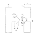
図1は、押圧係合工程を説明する説明図、図2は、接合工程を説明する説明図、図3は、接合構造体の第1実施形態を示す図であって、(a)は、断面図、(b)は、平面図、(c)は、底面図、図4は、接合構造体おける押圧係合部の変形例を示す断面図、図5は、接合構造体おける押圧係合部の他の変形例を示す断面図、図6は、接合構造体の第1実施形態の実施例を示す図であって、(a)は、斜視図、(b)は(a)の要部拡大断面図である。なお、断面図おいては、図面の見易さを考慮して断面のハッチングを省略する。 FIG. 1 is an explanatory view for explaining a pressing engagement process, FIG. 2 is an explanatory view for explaining a joining process, FIG. 3 is a view showing a first embodiment of a joined structure, and (a) Sectional view, (b) is a plan view, (c) is a bottom view, FIG. 4 is a sectional view showing a modification of the press engagement portion in the joint structure, and FIG. 5 is a press engagement in the joint structure. Sectional drawing which shows the other modification of a part, FIG. 6 is a figure which shows the Example of 1st Embodiment of a joining structure, Comprising: (a) is a perspective view, (b) is the principal of (a). FIG. In the cross-sectional view, the cross-sectional hatching is omitted in consideration of the visibility of the drawing.
−接合構造体の構成−
まず、本発明の第1実施形態の接合構造体1について説明する。
−Composition structure−
First, the
本実施形態の接合構造体1は、第1部材2と、第2部材3と、が接合領域BFで接合され、第2部材3には、第1部材2と係合させることにより、接合領域BFで、第2部材3を第1部材2に押圧させる押圧係合部30が備えられている(例えば、図3(a)〜(c)参照)。
In the
第1部材2は金属であり、金属の一例としては、鉄系金属、ステンレス系金属、銅系金属、アルミ系金属、マグネシウム系金属、および、それらの合金が挙げられる。また、金属成型体であってもよく、亜鉛ダイカスト、アルミダイカスト、粉末冶金などであってもよい。
The
第1部材2(金属)には、貫通孔23が形成されている(例えば、図1参照)。貫通孔23の開口径の大きさは、後述する第2部材3(可撓性の樹脂)の押圧係合部30を挿入させることが可能な程度である。また、貫通孔23の形状は、押圧係合部30が挿入されて第2部材3を第1部材2に押圧させるため、押圧力を均等にする観点から円形状が好ましいが、この形状に限られるものではない。
A through
第1部材2の表面の貫通孔23の周囲は、接合領域BFとされており、接合領域BFには、開口を有する凹状部21が複数形成されている(例えば、図3(a)、(b)参照)。図示例では、凹状部21は、断面的に見てほぼ円形の非貫通孔であるが、この形状に限定されるものではない。
The periphery of the through
凹状部21の開口径は、30μm以上、100μm以下が好ましい。これは、開口径が30μmを下回ると、後述する接合工程において、照射された接合用のレーザが凹状部21内に十分に閉じ込められず、接合用のレーザのエネルギーを熱に変換する変換効率が低下する場合があるためである。一方、開口径が100μmを上回ると、単位面積あたりの凹状部21の数が減少して、接合用のレーザのエネルギーを熱に変換する変換効率が低下する場合があるためである。また、凹状部21の深さは、10μm以上であることが好ましい。これは、深さが10μmを下回ると、接合用のレーザのエネルギーを熱に変換する変換効率が低下する場合があるためである。
The opening diameter of the
また、凹状部21の間隔(所定の凹状部21の中心と、所定の凹状部21と隣接する凹状部21の中心との距離)は、200μm以下であることが好ましい。これは、凹状部21の間隔が200μmを上回ると、単位面積あたりの凹状部21の数が減少して、接合用のレーザのエネルギーを熱に変換する変換効率が低下する場合があるためである。なお、凹状部21の間隔の下限の一例としては、凹状部21が重畳して潰れない距離である。また、凹状部21の間隔は等間隔であることが好ましい。これは、凹状部21が等間隔であると、接合用のレーザが照射される際の熱の分布が等方的になるためである。
The interval between the concave portions 21 (the distance between the center of the predetermined
凹状部21には、後述する第2部材3が充填されることにより、第1部材2と第2部材3とが接合される。ここで、本実施形態の凹状部21には、内側に突出する突出部22が形成されている。このように凹状部21の内周面に、内側に突出する突出部22が形成されている場合は、凹状部21に第2部材3が充填されると、突出部22によるアンカー効果によって第1部材2と第2部材3との接合強度を高めることができる。なお、凹状部21に突出部22が形成されていなくてもよい。
The
第2部材3は、レーザを透過する可撓性の樹脂であり、熱可塑性樹脂、又は、熱硬化性樹脂である。熱可塑性樹脂の一例としては、PVC(ポリ塩化ビニル)、PS(ポリスチレン)、AS(アクリロニトリル・スチレン)、ABS(アクリロニトリル・ブタジエン・スチレン)、PMMA(ポリメチルメタクリレート)、PE(ポリエチレン)、PP(ポリプロピレン)、PC(ポリカーボネート)、m−PPE(変性ポリフェニレンエーテル)、PA6(ポリアミド6)、PA66(ポリアミド66)、POM(ポリアセタール)、PET(ポリエチレンテレフタレート)、PBT(ポリブチレンテレフタレート)、PSF(ポリサルホン)、PAR(ポリアリレート)、PEI(ポリエーテルイミド)、PPS(ポリフェニレンサルファイド)、PES(ポリエーテルサルホン)、PEEK(ポリエーテルエーテルケトン)、PAI(ポリアミドイミド)、LCP(液晶ポリマー)、PVDC(ポリ塩化ビニリデン)、PTFE(ポリテトラフルオロエチレン)、PCTFE(ポリクロロトリフルオロエチレン)、および、PVDF(ポリフッ化ビニリデン)が挙げられる。また、TPE(熱可塑性エラストマ)であってもよく、TPEの一例としては、TPO(オレフィン系)、TPS(スチレン系)、TPEE(エステル系)、TPU(ウレタン系)、TPA(ナイロン系)、および、TPVC(塩化ビニル系)が挙げられる。
The
熱硬化性樹脂の一例としては、EP(エポキシ)、PUR(ポリウレタン)、UF(ユリアホルムアルデヒド)、MF(メラミンホルムアルデヒド)、PF(フェノールホルムアルデヒド)、UP(不飽和ポリエステル)、および、SI(シリコーン)が挙げられる。また、FRP(繊維強化プラスチック)であってもよい。 Examples of thermosetting resins include EP (epoxy), PUR (polyurethane), UF (urea formaldehyde), MF (melamine formaldehyde), PF (phenol formaldehyde), UP (unsaturated polyester), and SI (silicone) Is mentioned. Further, it may be FRP (fiber reinforced plastic).
なお、熱可塑性樹脂および熱硬化性樹脂には、充填剤が添加されていてもよい。充填剤の一例としては、無機系充填剤(ガラス繊維、無機塩類など)、金属系充填剤、有機系充填剤、および、炭素繊維などが挙げられる。 Note that a filler may be added to the thermoplastic resin and the thermosetting resin. Examples of the filler include inorganic fillers (glass fibers, inorganic salts, etc.), metal fillers, organic fillers, and carbon fibers.
第2部材3には、第1部材2と係合させることにより、接合領域BFで第2部材3を第1部材2に押圧させる押圧係合部30が備えられている(例えば図1参照)。本実施形態では、押圧係合部30が、第2部材3の中央付近に突設されているが、押圧係合部30が突設されている位置は、この例に限られない。また、押圧係合部30の数も1個に限られるものではなく、複数形成されていてもよい。
The
押圧係合部30は、第1部材2と係合する鉤部32と、鉤部32と第2部材3とを結ぶ連結部31と、から構成されている。
The
鉤部32は、押圧係合部30を貫通孔23に挿入する際に、挿入しやすくガイドするものであり、図示例では、円錐形状である(図3(a)参照)。また、図示例の鉤部32の長さLFは、接合領域BFの領域長と、略等しく設計されている。すなわち、押圧係合部30が第1部材2の裏面と接触している領域の領域長は、接合領域BFの領域長と、略等しく設計されている。
The
鉤部32の角部rは丸角とされている。このように、鉤部32の角部rを丸角とすることにより、角部が鋭角である場合と比較して、角部のバリの影響、成型制度の影響(角部の形状出来栄え、つまり均等な押圧に必要な平面度に関する精度)等による押圧ばらつきを減少することができる。すなわち、後述する接合構造体1の製造方法の押圧係合工程において、第2部材3を第1部材2に押圧させやすくすることができる。
The corner portion r of the
連結部31は、貫通孔23と密着するものであり、図示例では、円柱形状である。連結部31の長さlは、第1部材2の厚みtよりも短く設計されている(例えば、図1参照)。すなわち、押圧係合部30における、第2部材3からの突設位置から第1部材2の裏面と接触される位置までの長さlは、第1部材2の厚みtよりも短く設計されている。
The connecting
なお、押圧係合部30の形状は、図4に示すように押圧係合部30の中央部が割れている割ピン形状や、図5に示すように鉤部32が平頭のリベット形状であってもよい。
The shape of the
なお、本実施形態では、第1部材2を、金属として説明したが、この例に限られず、熱可塑性樹脂、又は、熱硬化樹脂としてもよい。第1部材2に熱可塑性樹脂、又は、熱硬化性樹脂を用いた場合は、後述する接合構造体1の製造方法の接合工程において、接合領域BFに向けてレーザを照射した際に、第1部材2及び第2部材3が互いに溶融されて接合されるため、第1部材2に凹状部21を設けなくても第1部材2と第2部材3とを接合することができる。なお、第1部材2に熱可塑性樹脂、又は、熱硬化樹脂を用いた場合であっても凹状部21を設けてもよく、凹状部21に突出部22を設けた場合は、アンカー効果により、より強固に第1部材2と第2部材3とを接合することができる。
In the present embodiment, the
−接合構造体の製造方法−
次に、本実施形態に係る接合構造体1の製造方法について説明する。
-Manufacturing method of bonded structure-
Next, a method for manufacturing the bonded
本実施形態に係る接合構造体1の製造方法は、凹状部形成工程と、押圧係合工程と、接合工程と、を備える。以下、各工程について説明する。
The manufacturing method of the
・凹状部形成工程
凹状部形成工程は、第1部材2の表面の接合領域BFに、第2部材3が充填される凹状部21を形成する工程である。なお、本実施形態では、第1部材2を金属とし、第2部材3を樹脂として説明する。
-Recessed part formation process A recessed part formation process is a process of forming the recessed
凹状部21は、レーザ加工処理、ブラスト処理、サンドペーパ処理、陽極酸化処理、放電加工処理、エッチング処理、およびプレス加工処理等の方法で形成される。本実施形態では、レーザ加工処理によって凹状部21を形成する方法について詳述する。
The
凹状部21を形成する加工用レーザの種類としては、パルス発振が可能なものが好ましく、ファイバレーザ、YAGレーザ、YVO4レーザ、半導体レーザ、炭酸ガスレーザ、エキシマレーザが選択でき、レーザの波長を考慮すると、ファイバレーザ、YAGレーザ、YAGレーザの第2高調波、YVO4レーザ、半導体レーザが好ましい。凹状部21は、断面的に見てほぼ円形の非貫通孔であり、第1部材2の表面に複数形成される(例えば、図3(b)参照)。
The type of processing laser that forms the
凹状部21を形成する装置の一例としては、オムロン製のファイバレーザマーカMXZ2000又はMX−Z2050を挙げることができる。このファイバレーザマーカでは、1パルスが複数のサブパルスで構成されるレーザを照射することが可能である。このため、レーザのエネルギーを深さ方向に集中させやすいので、凹状部21を形成するのに好適である。
As an example of an apparatus for forming the
具体的には、第1部材2にレーザが照射されると、第1部材2が局部的に溶融されることにより凹状部21の形成が進行する。このとき、レーザが複数のサブパルスで構成されているため、溶融された第1部材2が飛散されにくく、凹状部21の近傍に堆積されやすい。そして、凹状部21の形成が進行すると、溶融された第1部材2が凹状部21の内部に堆積されることにより、凹状部21の内周面に、内側に突出する突出部22が形成される。
Specifically, when the
なお、上記ファイバレーザマーカによる加工条件としては、サブパルスの1周期が15ns以下であることが好ましい。これは、サブパルスの1周期が15nsを超えると、熱伝導によりエネルギーが拡散しやすくなり、突出部22を有する凹状部21を形成しにくくなるためである。なお、サブパルスの1周期は、サブパルスの1回分の照射時間と、そのサブパルスの照射が終了されてから次回のサブパルスの照射が開始されるまでの間隔との合計時間である。
As a processing condition by the fiber laser marker, it is preferable that one period of the sub-pulse is 15 ns or less. This is because when one period of the sub-pulse exceeds 15 ns, energy is easily diffused by heat conduction, and it becomes difficult to form the
また、上記ファイバレーザマーカによる加工条件としては、1パルスのサブパルス数は、2以上50以下であることが好ましい。これは、サブパルス数が50を超えると、サブパルスの単位あたりの出力が小さくなり、突出部22を有する凹状部21を形成しにくくなるためである。
Further, as a processing condition by the fiber laser marker, the number of subpulses of one pulse is preferably 2 or more and 50 or less. This is because if the number of subpulses exceeds 50, the output per unit of subpulses becomes small, and it becomes difficult to form the
・押圧係合工程
押圧係合工程は、第1部材2の表面と第2部材3とを隣接配置させるとともに、押圧係合部30によって第2部材3を第1部材2に押圧させる工程である。
Press Engagement Step The press engagement step is a step of placing the surface of the
具体的には、第1部材2に設けられた貫通孔23に、押圧係合部30の鉤部32を弾性変形させながら挿入する。ここで、上述したとおり、本実施形態(図2参照)では、長さlは、第1部材2の厚みtよりも短く設計されており、押圧係合部30を貫通孔23に挿入すると、第2部材3の上面が凹面となるように撓んで弾性変形されるので、長さlと厚みtの差分に起因する押圧力を、第2部材3は第1部材2に対して掛けることができる。
Specifically, the
なお、押圧係合部30の鉤部の長さLFは、接合領域BFの領域長と、略等しい。
Note that the length LF of the flange portion of the
以上により、第2部材3と第1部材2とを押圧係合させることができる。
Thus, the
・接合工程
接合工程は、接合領域BFにレーザを照射して、第1部材2と第2部材3とを互いに接合する工程である。具体的には、配置工程において、第1部材2と第2部材3とを押圧して接触させた後、接合用のレーザを第1部材2の表面に向けて照射する。
-Joining process A joining process is a process of irradiating the joining area BF with a laser to join the
ここで、レーザ照射は、第2部材3(樹脂)がレーザ透過性を有する場合は、第2部材3側からレーザを照射してもよいし、第1部材2(金属)側からレーザを照射してもよい。一方で、第2部材3(樹脂)がレーザ透過性を有しない場合は、第1部材2(金属)側からレーザを照射する。なお、接合用のレーザの種類としては、ファイバレーザ、YAGレーザ、YVO4レーザ、半導体レーザ、炭酸ガスレーザ、エキシマレーザが選択できる。
Here, when the second member 3 (resin) has laser transparency, the laser irradiation may be performed by irradiating the laser from the
レーザを第1部材2の接合領域BFに照射することにより、レーザのエネルギーが第1部材2で熱に変換され、第1部材2の表面の温度が高くなる。これにより、第1部材2の表面近傍の第2部材3が溶融され、その第2部材3が凹状部21に充填される。これとともに、前述した押圧係合工程で弾性変形している第2部材3は、第2部材3の溶融により弾性変形が緩和される。すなわち、第2部材3の上面の凹面形状が緩和される。
By irradiating the bonding region BF of the
その後、第2部材3が固化されることにより、第2部材3が第1部材2に接合された接合構造体1を製造できる(図3(a)参照)。
Then, the
ここで、第1部材2の接合領域BFにレーザを照射する際に、接合領域BF内においてレーザを走査させるとともに、前記走査を同一軌跡で複数回行ってもよい。この場合は、レーザの走査を同一軌跡で複数回行われるため、第1部材2の温度が上昇し、より効果的に第2部材3と第1部材2とを接合することができる。
Here, when irradiating the bonding region BF of the
なお、本実施形態では、第1部材2を、金属として説明したが、この例に限られず、熱可塑性樹脂、又は、熱硬化樹脂としてもよい。第1部材2に熱可塑性樹脂、又は、熱硬化性樹脂を用いた場合は、接合工程において接合領域BFに向けてレーザを照射した際に、第1部材2及び第2部材3が互いに溶融して接合されるため、第1部材2に凹状部21を設けなくても第1部材2と第2部材3とを接合することができる(すなわち、凹状部形成工程を行わなくてもよい)。なお、第1部材2に凹状部21を設けた場合(すなわち、凹状形成工程を行った後に、押圧係合工程及び接合工程を行った場合)は、アンカー効果により、より強固に第1部材2と第2部材3とを接合することができる。
In the present embodiment, the
−接合構造体の実験例−
次に、上記した第1実施形態の効果を確認するために行った実験例について図6を参照しながら説明する。
-Experimental example of joint structure-
Next, an experimental example performed to confirm the effect of the first embodiment described above will be described with reference to FIG.
この実験例では、第1実施形態に対応する接合構造体の実施例を実施例1−1及び1−2並びに比較例1−1及び1−2による接合構造体を作製した。 In this experimental example, a bonded structure according to Examples 1-1 and 1-2 and Comparative Examples 1-1 and 1-2 of the bonded structure corresponding to the first embodiment was manufactured.
なお、第1部材及び第2部材の大きさは、互いに長さ100mm、幅29mm、厚み3mmとしたが、第1部材の材質及び第2部材の材質は、後述する表1に示すとおりである。 The first member and the second member have a length of 100 mm, a width of 29 mm, and a thickness of 3 mm. The material of the first member and the material of the second member are as shown in Table 1 described later. .
また、第1部材がSUS304で、第2部材がPMMA(三菱レイヨン製のアクリライト(登録商標))の場合に、接合工程に用いたレーザは、半導体レーザであり、波長が808nm、発振モードは連続発振、レーザ出力は30W、焦点径は4mm、走査速度は1mm/secとした。 When the first member is SUS304 and the second member is PMMA (Acrylite (registered trademark) manufactured by Mitsubishi Rayon), the laser used in the bonding process is a semiconductor laser, the wavelength is 808 nm, and the oscillation mode is Continuous oscillation, laser output was 30 W, focal spot diameter was 4 mm, and scanning speed was 1 mm / sec.
また、第1部材がPBT(ウィンテックポリマー製のジェラネックス(登録商標)3316)で、第2部材がPMMAの場合に、接合工程に用いたレーザは、半導体レーザであり、波長が808nm、発振モードは連続発振、レーザ出力は1W、焦点径は4mm、走査速度は1mm/secとした。 When the first member is PBT (Geranex (registered trademark) 3316 made by Wintech Polymer) and the second member is PMMA, the laser used in the bonding process is a semiconductor laser, the wavelength is 808 nm, and the oscillation The mode was continuous oscillation, the laser output was 1 W, the focal diameter was 4 mm, and the scanning speed was 1 mm / sec.
また、第1部材がSUS304の場合に、凹状部形成工程で用いたレーザは、ファイバレーザであり、波長が1062nm、発振モードはパルス発振(周波数10kHz)、レーザ出力は3.8W、走査速度は650mm/sec、走査回数は20回、照射間隔は65μm、サブパルス数は20個とした。 When the first member is SUS304, the laser used in the concave portion forming step is a fiber laser, the wavelength is 1062 nm, the oscillation mode is pulse oscillation (frequency 10 kHz), the laser output is 3.8 W, and the scanning speed is 650 mm / sec, the number of scans was 20, the irradiation interval was 65 μm, and the number of subpulses was 20.
また、第1部材がPBTの場合に、凹状部形成工程で用いたレーザは、ファイバレーザであり、波長が1062nm、発振モードはパルス発振(周波数10kHz)、レーザ出力は3.8W、走査速度は650mm/sec、走査回数は20回、照射間隔は65μm、サブパルス数は20個とした。 When the first member is PBT, the laser used in the concave portion forming step is a fiber laser, the wavelength is 1062 nm, the oscillation mode is pulse oscillation (frequency 10 kHz), the laser output is 3.8 W, and the scanning speed is 650 mm / sec, the number of scans was 20, the irradiation interval was 65 μm, and the number of subpulses was 20.
また、接合状態の評価は、インストロン製の電気機械式万能試験機5900を用いて行った。具体的には、剥離方向(垂直方向)に引張速度5mm/minで試験を行い、試験後に第1部材と第2部材とが剥離したものを合否判定×、第1部材と第2部材とが剥離しなかったものを合否判定○として評価した。評価結果を表1に示す。 Moreover, evaluation of the joining state was performed using the electromechanical universal testing machine 5900 made from Instron. Specifically, a test is performed in the peeling direction (vertical direction) at a tensile speed of 5 mm / min, and the first member and the second member are peeled off after the test. What did not peel was evaluated as a pass / fail judgment o. The evaluation results are shown in Table 1.

[比較例1−1]
比較例1−1の接合構造体は、第1部材をSUS304とし、第2部材をPMMA樹脂とするとともに、第2部材には押圧係合部を設けていない。
[Comparative Example 1-1]
In the joined structure of Comparative Example 1-1, the first member is SUS304, the second member is PMMA resin, and the second member is not provided with a pressing engagement portion.
また、凹状部形成工程において第1部材に凹状部を形成し、接合工程において接合領域にレーザを照射することにより、第1部材の凹状部に第2部材を充填させて、第1部材と第2部材とを接合させた。 In addition, the concave portion is formed in the first member in the concave portion forming step, and the bonding region is irradiated with laser in the bonding step, so that the concave portion of the first member is filled with the second member, and the first member and the first member Two members were joined.
この接合構造体を、剥離方向(垂直方向)に引張速度5mm/minで試験を行った結果、第1部材と第2部材とが剥離した。 As a result of testing this bonded structure in the peeling direction (vertical direction) at a tensile speed of 5 mm / min, the first member and the second member were peeled off.
[比較例1−2]
比較例1−2の接合構造体は、第1部材をPBTとし、第2部材をPMMA樹脂とするとともに、第2部材には押圧係合部を設けていない。
[Comparative Example 1-2]
In the joint structure of Comparative Example 1-2, the first member is PBT, the second member is PMMA resin, and the second member is not provided with a pressing engagement portion.
また、凹状部形成工程において第1部材に凹状部を形成し、接合工程においてレーザを照射することにより、第1部材の凹状部に第2部材を充填させて、第1部材と第2部材とを接合させた。 Further, the concave portion is formed in the first member in the concave portion forming step, and the second member is filled in the concave portion of the first member by irradiating the laser in the joining step, and the first member and the second member Were joined.
この接合構造体を、剥離方向(垂直方向)に引張速度5mm/minで試験を行った結果、第1部材と第2部材とが剥離した。 As a result of testing this bonded structure in the peeling direction (vertical direction) at a tensile speed of 5 mm / min, the first member and the second member were peeled off.
[実施例1−1]
実施例1−1の接合構造体100は、第1部材200をSUS304とし、第2部材300をPMMA樹脂とするとともに、第1部材200に貫通孔(φ5mm)を2箇所形成し、貫通孔に対応させて第2部材300に押圧係合部310を設けた。
[Example 1-1]
In the joining
また、凹状部形成工程において第1部材200に凹状部を形成し、押圧係合工程によって第2部材300を第1部材200に押圧させ、接合工程において接合領域BF1にレーザを照射することにより、第1部材200の凹状部に第2部材300を充填させて、第1部材200と第2部材300とを接合領域BF1で接合させた。
Further, by forming a concave portion in the
この接合構造体100について押圧係合部310の鉤部320を切除した後に、接合構造体100を剥離方向(垂直方向)に引張速度5mm/minで試験を行った結果、第1部材200と第2部材300とは剥離しなかった。
As a result of testing the bonded
[実施例1−2]
実施例1−2の接合構造体100は、第1部材200をSUS304とし、第2部材300をPMMA樹脂とするとともに、第1部材200に貫通孔を2箇所形成し、貫通孔に対応させて第2部材300に押圧係合部310を設けた。
[Example 1-2]
In the joined
また、凹状部形成工程において第1部材200に凹状部を形成し、押圧係合工程によって第2部材300を第1部材200に押圧させ、接合工程において接合領域BF1にレーザを照射することにより、第1部材200の凹状部に第2部材300を充填させて、第1部材200と第2部材300とを接合領域BF1で接合させた。
Further, by forming a concave portion in the
この接合構造体100について押圧係合部310の鉤部320を切除した後に、接合構造体100を剥離方向(垂直方向)に引張速度5mm/minで試験を行った結果、第1部材200と第2部材300とは剥離しなかった。
As a result of testing the bonded
以上、説明したとおり、第2部材300には、押圧係合部310が備えられているので、押圧係合工程により、第2部材300を第1部材200に押圧させることができ、その後の接合工程によって、接合領域BF1にレーザを照射して第1部材200と第2部材300とが互いに位置決めされた状態で接合することができる。これにより、従来技術と異なり、接圧治具等の押圧装置を用いずに、第2部材300と第1部材200とを押圧させた状態で精度よく第1部材200と第2部材300とを接合することができる。
As described above, since the
また、本実施形態では、押圧係合工程により、第1部材200の貫通孔に、第2部材300の押圧係合部310を挿入するだけで、第2部材300を第1部材200に押圧させることができるので、押圧係合工程を容易に行うことができる。
In the present embodiment, the
(第2実施形態)
以下、本発明の第2実施形態の接合構造体1及びこの接合構造体1の製造方法について図7〜10を参照しながら説明する。
(Second Embodiment)
Hereinafter, the joining
図7は、接合構造体の製造方法における押圧係合工程の第2実施形態を説明する説明図、図8は、接合構造体の製造方法における接合工程の第2実施形態を説明する説明図、図9は、本発明に係る接合構造体の第2実施形態の断面図、図10は、接合構造体の第2実施形態の実施例を示す図であって、(a)は、斜視図、(b)は(a)の要部拡大断面図である。 FIG. 7 is an explanatory diagram for explaining a second embodiment of the pressing engagement process in the method for manufacturing the joined structure, and FIG. 8 is an explanatory diagram for explaining a second embodiment of the joining process in the method for producing the joined structure. FIG. 9 is a cross-sectional view of the second embodiment of the joint structure according to the present invention, FIG. 10 is a diagram showing an example of the second embodiment of the joint structure, and (a) is a perspective view, (B) is a principal part expanded sectional view of (a).
なお、本実施形態は、接合構造体1の押圧係合部の構成が異なるだけであるので、以下、その相違点についてのみ説明し、同一の構成要素については、同一符号を付してその説明を省略する。
In addition, since this embodiment only differs in the structure of the press engagement part of the joining
−接合構造体の構成−
まず、本発明の第2実施形態の接合構造体1について説明する。
−Composition structure−
First, the
本実施形態の接合構造体1は、第1部材2と、第2部材3と、が接合領域BFで接合され、第2部材3には、第1部材2と係合させることにより、接合領域BFで、第2部材3を第1部材2に押圧させる押圧係合部30´が備えられた接合構造体1であって、本実施形態では、押圧係合部30´は、第1部材2の裏面外周部と当接して係合させるものである。
In the
第1部材2は金属であり、第1部材2の外周端部(第1部材2の表面の接合領域BF)には、第1部材2の表面に開口を有する凹状部21が形成されている(例えば、図9参照)。図示例では、凹状部21は、断面的に見てほぼ円形の非貫通孔であるが、この形状に限定されるものではない。
The
第2部材3は、熱可塑性樹脂、又は、熱硬化性樹脂であり、第1部材2と係合させることにより、接合領域BFで第2部材3を第1部材2に押圧させる押圧係合部30´が備えられている。本実施形態では、第2部材3の外周端部に押圧係合部30´が形成されている。
The
押圧係合部30´は、第1部材2と係合する鉤部32´と、鉤部32´と第2部材3とを結ぶ連結部31´と、から構成されている。
The
鉤部32´は、第1部材2の裏面外周部と当接するものである(図7及び図9参照)。図示例の鉤部32´の長さLFは、接合領域BFの領域長と、略等しく設計されている。すなわち、押圧係合部30´が第1部材2の裏面と接触している領域の領域長は、接合領域BFの領域長と、略等しく設計されている。
The
連結部31´は、第1部材2の側面と当接するものである(図7及び図9参照)。図示例では、連結部31´の長さlは、第1部材2の厚みtよりも短く設計されている。すなわち、押圧係合部30´における、第2部材3からの突設位置から第1部材2の裏面と接触される位置までの長さlは、第1部材2の厚みtよりも短く設計されている。
The connecting
なお、本実施形態では、第1部材2を、金属として説明したが、この例に限られず、熱可塑性樹脂、又は、熱硬化樹脂としてもよい。第1部材2に熱可塑性樹脂、又は、熱硬化性樹脂を用いた場合は、後述する接合構造体の製造方法の接合工程において、第1部材2及び第2部材3の接合領域BFに向けてレーザを照射した場合、第1部材2及び第2部材3が互いに溶融されて接合されるため、第1部材2に凹状部21を設けなくても第1部材2と第2部材3とを接合することができる。なお、第1部材2に凹状部21を設けた場合は、アンカー効果により、より強固に第1部材2と第2部材3とを接合することができる。
In the present embodiment, the
−接合構造体の製造方法−
次に、本実施形態に係る接合構造体1の製造方法について説明する。
-Manufacturing method of bonded structure-
Next, a method for manufacturing the bonded
本実施形態に係る接合構造体の製造方法は、凹状部形成工程と、押圧係合工程と、接合工程と、を備える。以下、各工程について説明する。 The manufacturing method of the junction structure concerning this embodiment is provided with a concave part formation process, a press engagement process, and a joining process. Hereinafter, each step will be described.
・凹状部形成工程
凹状部形成工程により、第1部材2の接合領域BFに、第2部材3が充填される凹状部21を形成する。上述したとおり、本実施形態では、凹状部21は、第1部材2の表面の外周端部に形成する。このとき、レーザが複数のサブパルスで構成されている場合は、凹状部21の内周面に、内側に突出する突出部22を形成できる。
-Concave part formation process The
・押圧係合工程
押圧係合工程により、第1部材2の表面と第2部材3とを隣接配置させるとともに、押圧係合部30によって第2部材3を第1部材2に押圧させる。
Press Engagement Step In the press engagement step, the surface of the
具体的には、鉤部32´を弾性変形させながら第1部材2の裏面の外周端部に当接させる。ここで、上述したとおり、本実施形態(図8参照)では、長さlは、第1部材2の厚みtよりも短く設計されており、押圧係合部30´を第1部材2の裏面の外周端部に当接させると、第2部材3の上面が凸面となるように撓んで弾性変形されるので、長さlと厚みtの差分に起因する押圧力を、第2部材3は第1部材2に対して掛けることができる。
Specifically, the
以上により、第2部材3と第1部材2とを押圧係合させることができる。
Thus, the
・接合工程
接合工程により、接合領域BFにレーザを照射して、第1部材2と第2部材3とを互いに接合する。
-Joining process In the joining process, the
レーザを第1部材2の接合領域BFに照射することにより、第1部材2の表面近傍の第2部材3が溶融され、その第2部材3が凹状部21に充填される。これとともに、前述した押圧係合工程で弾性変形している第2部材3は、第2部材3の溶融により弾性変形が緩和される。すなわち、第2部材3の上面の凸面形状が緩和される。
By irradiating the bonding region BF of the
その後、第2部材3が固化されることにより、第2部材3が第1部材2に接合された接合構造体1を製造できる(図9参照)。
Then, the
なお、本実施形態では、第1部材2を、金属として説明したが、この例に限られず、熱可塑性樹脂、又は、熱硬化樹脂としてもよい。第1部材2に熱可塑性樹脂、又は、熱硬化性樹脂を用いた場合は、接合工程において、第1部材2及び第2部材3の接合領域BFに向けてレーザを照射した際に、第1部材2及び第2部材3が互いに溶融して接合されるため、第1部材2に凹状部21を設けなくても第1部材2と第2部材3とを接合することができる(すなわち、凹状部形成工程を行わなくてもよい)。なお、第1部材2に凹状部21を設けた場合(すなわち、凹状形成工程を行った後に、押圧係合工程及び接合工程を行った場合)は、アンカー効果により、より強固に第1部材2と第2部材3とを接合することができる。
In the present embodiment, the
−接合構造体の実験例−
次に、上記した第2実施形態の効果を確認するために行った実験例について図10を参照しながら説明する。
-Experimental example of joint structure-
Next, an experimental example performed to confirm the effect of the second embodiment described above will be described with reference to FIG.
この実験例では、第2実施形態に対応する接合構造体の実施例を実施例2−1及び2−2並びに比較例2−1及び2−2による接合構造体を作製した。 In this experimental example, a bonded structure according to examples 2-1 and 2-2 and comparative examples 2-1 and 2-2 of the bonded structure corresponding to the second embodiment was manufactured.
なお、第1部材及び第2部材の大きさは、互いに長さ100mm、幅29mm、厚み3mmとしたが、第1部材の材質及び第2部材の材質は、表2に示すとおりである。 The first member and the second member have a length of 100 mm, a width of 29 mm, and a thickness of 3 mm. The materials of the first member and the second member are as shown in Table 2.
また、第1部材がSUS304で、第2部材がPMMA(三菱レイヨン製のアクリライト(登録商標))の場合に、接合工程に用いたレーザは、半導体レーザであり、波長が808nm、発振モードは連続発振、レーザ出力は30W、焦点径は4mm、走査速度は1mm/secとした。 When the first member is SUS304 and the second member is PMMA (Acrylite (registered trademark) manufactured by Mitsubishi Rayon), the laser used in the bonding process is a semiconductor laser, the wavelength is 808 nm, and the oscillation mode is Continuous oscillation, laser output was 30 W, focal spot diameter was 4 mm, and scanning speed was 1 mm / sec.
また、第1部材がPBT(ウィンテックポリマー製のジェラネックス(登録商標)3316)で、第2部材がPMMAの場合に、接合工程に用いたレーザは、半導体レーザであり、波長が808nm、発振モードは連続発振、レーザ出力は1W、焦点径は4mm、走査速度は1mm/secとした。 When the first member is PBT (Geranex (registered trademark) 3316 made by Wintech Polymer) and the second member is PMMA, the laser used in the bonding process is a semiconductor laser, the wavelength is 808 nm, and the oscillation The mode was continuous oscillation, the laser output was 1 W, the focal diameter was 4 mm, and the scanning speed was 1 mm / sec.
また、第1部材がSUS304の場合に、凹状部形成工程で用いたレーザは、ファイバレーザであり、波長が1062nm、発振モードはパルス発振(周波数10kHz)、レーザ出力は3.8W、走査速度は650mm/sec、走査回数は20回、照射間隔は65μm、サブパルス数は20個とした。 When the first member is SUS304, the laser used in the concave portion forming step is a fiber laser, the wavelength is 1062 nm, the oscillation mode is pulse oscillation (frequency 10 kHz), the laser output is 3.8 W, and the scanning speed is 650 mm / sec, the number of scans was 20, the irradiation interval was 65 μm, and the number of subpulses was 20.
また、第1部材がPBTの場合に、凹状部形成工程で用いたレーザは、ファイバレーザであり、波長が1062nm、発振モードはパルス発振(周波数10kHz)、レーザ出力は3.8W、走査速度は650mm/sec、走査回数は20回、照射間隔は65μm、サブパルス数は20個とした。 When the first member is PBT, the laser used in the concave portion forming step is a fiber laser, the wavelength is 1062 nm, the oscillation mode is pulse oscillation (frequency 10 kHz), the laser output is 3.8 W, and the scanning speed is 650 mm / sec, the number of scans was 20, the irradiation interval was 65 μm, and the number of subpulses was 20.
また、接合状態の評価は、インストロン製の電気機械式万能試験機5900を用いて行った。具体的には、せん断方向(水平方向)に引張速度5mm/minで試験を行い、試験後に第1部材と第2部材とが剥離したものを合否判定×、第1部材と第2部材とが剥離しなかったものを合否判定○として評価した。評価結果を表2に示す。 Moreover, evaluation of the joining state was performed using the electromechanical universal testing machine 5900 made from Instron. Specifically, a test is performed in the shear direction (horizontal direction) at a tensile speed of 5 mm / min, and the first member and the second member peeled off after the test is determined as pass / fail ×, the first member and the second member What did not peel was evaluated as a pass / fail judgment o. The evaluation results are shown in Table 2.
[比較例2−1]
比較例2−1の接合構造体は、第1部材をSUS304とし、第2部材をPMMA樹脂とするとともに、第2部材には押圧係合部を設けていない。
[Comparative Example 2-1]
In the joined structure of Comparative Example 2-1, the first member is SUS304, the second member is PMMA resin, and the second member is not provided with a pressing engagement portion.
また、凹状部形成工程において第1部材に凹状部を形成し、接合工程において接合領域にレーザを照射することにより、第1部材の凹状部に第2部材を充填させて、第1部材と第2部材とを接合させた。 In addition, the concave portion is formed in the first member in the concave portion forming step, and the bonding region is irradiated with laser in the bonding step, so that the concave portion of the first member is filled with the second member, and the first member and the first member Two members were joined.
この接合構造体を、せん断方向(水平方向)に引張速度5mm/minで試験を行った結果、第1部材と第2部材とが剥離した。 As a result of testing this bonded structure in the shearing direction (horizontal direction) at a tensile speed of 5 mm / min, the first member and the second member were peeled off.
[比較例2−2]
比較例2−2の接合構造体は、第1部材をPBTとし、第2部材をPMMA樹脂とするとともに、第2部材には押圧係合部を設けていない。
[Comparative Example 2-2]
In the joint structure of Comparative Example 2-2, the first member is PBT, the second member is PMMA resin, and the second member is not provided with a pressing engagement portion.
また、凹状部形成工程において第1部材に凹状部を形成し、接合工程においてレーザを照射することにより、第1部材の凹状部に第2部材を充填させて、第1部材と第2部材とを接合させた。 Further, the concave portion is formed in the first member in the concave portion forming step, and the second member is filled in the concave portion of the first member by irradiating the laser in the joining step, and the first member and the second member Were joined.
この接合構造体を、せん断方向(水平方向)に引張速度5mm/minで試験を行った結果、第1部材と第2部材とが剥離した。 As a result of testing this bonded structure in the shearing direction (horizontal direction) at a tensile speed of 5 mm / min, the first member and the second member were peeled off.
[実施例2−1]
実施例2−1の接合構造体100´は、第1部材200´をSUS304とし、第2部材300´をPMMA樹脂とするとともに、第2部材300´には、第1部材200´と係合させることによって第2部材を第1部材に押圧させる押圧係合部310´(幅5mm、長さ15mm)が設けられている。
[Example 2-1]
In the joined
また、凹状部形成工程において第1部材200´に凹状部を形成し、押圧係合工程によって第2部材300´を第1部材200´に押圧させ、接合工程において接合領域BF2にレーザを照射することにより、第1部材200´の凹状部に第2部材300´を充填させて、第1部材200´と第2部材300´とを接合領域BF2で接合させた。
In addition, a concave portion is formed in the
この接合構造体100´を、せん断方向(水平方向)に引張速度5mm/minで試験を行った結果、第1部材2と第2部材3とは剥離しなかった。
As a result of testing this bonded
[実施例2−2]
実施例2−2の接合構造体100´は、第1部材200´をPBTとし、第2部材300´をPMMA樹脂とするとともに、第2部材300´には、第1部材200´と係合させることによって第2部材300´を第1部材200´に押圧させる押圧係合部310´(幅5mm、長さ15mm)が設けられている。
[Example 2-2]
In the joining
また、凹状部形成工程において第1部材200´に凹状部を形成し、押圧係合工程によって第2部材300´を第1部材200´に押圧させ、接合工程において接合領域BF2にレーザを照射することにより、第1部材200´の凹状部に第2部材300´を充填させて、第1部材200´と第2部材300´とを接合領域BF2で接合させた。
In addition, a concave portion is formed in the
この接合構造体100´を、せん断方向(水平方向)に引張速度5mm/minで試験を行った結果、第1部材200´と第2部材300´とは剥離しなかった。
As a result of testing this bonded
以上、説明したとおり、第2部材300´には、押圧係合部310´が備えられているので、押圧係合工程により、第2部材300´を第1部材200´に押圧させることができ、その後の接合工程によって、接合領域BF2にレーザを照射して第1部材200´と第2部材300´とが互いに位置決めされた状態で接合することができる。これにより、従来技術と異なり、接圧治具等の押圧装置を用いずに、第2部材300´と第1部材200´とを押圧させた状態で精度よく第1部材200´と第2部材300´とを接合することができる。
As described above, the
また、第2部材300´の押圧係合部310´は、第1部材200´の裏面外周部と当接して係合させるものであるので、押圧係合工程により、第1部材200´の裏面外周部に、第2部材300´の押圧係合部310´を当接させるだけで、第2部材300´を第1部材200´に押圧させることができる。したがって、押圧係合工程を容易に行うことができる。
Further, the
なお、上記に示した本発明の実施形態及び実施例はいずれも本発明を具体化した例であって、本発明の技術的範囲を限定する性格のものではない。 The above-described embodiments and examples of the present invention are all examples of the present invention, and are not of a nature that limits the technical scope of the present invention.
1、100、100´ 接合構造体
2、200、200´ 第1部材
21 凹状部
22 突出部
23 貫通孔
3、300、300´ 第2部材
30、30´、310 押圧係合部
31、31´ 連結部
32、32´ 鉤部
r 角部
BF、BF1、BF2 接合領域
1, 100, 100 ′
Claims (8)
前記第1部材の表面と前記第2部材とを隣接配置させるとともに、前記第2部材に設けられた押圧係合部によって、前記接合領域で前記第2部材を前記第1部材に押圧させる押圧係合工程と、
前記接合領域にレーザを照射して、前記第1部材と前記第2部材とを互いに接合する接合工程と、が備えられ、
前記押圧係合部は、前記第2部材から突設されており、
前記押圧係合部において、前記第2部材からの突設位置から前記第1部材の裏面と接触される位置までの長さは、前記第1部材の厚みよりも短く設計されていることを特徴とする接合構造体の製造方法。 The first member and the second member are a manufacturing method of a joined structure joined in a joining region,
A pressing member that causes the surface of the first member and the second member to be disposed adjacent to each other, and causes the second member to be pressed against the first member in the joining region by a pressing engagement portion provided on the second member. Joint process,
A joining step of irradiating the joining region with a laser to join the first member and the second member to each other ; and
The pressing engagement portion protrudes from the second member,
In the pressing engagement portion, the length from the projecting position from the second member to the position in contact with the back surface of the first member is designed to be shorter than the thickness of the first member. A method for manufacturing a joined structure.
前記第1部材には、前記押圧係合部が挿入される貫通孔が備えられており、
前記押圧係合工程では、前記貫通孔に前記押圧係合部を挿入させることによって、前記第2部材と前記第1部材とを係合させることを特徴とする接合構造体の製造方法。 A method for manufacturing a joined structure according to claim 1,
The first member is provided with a through hole into which the pressing engagement portion is inserted,
In the pressing engagement step, the second member and the first member are engaged with each other by inserting the pressing engagement portion into the through hole.
前記押圧係合部は、前記第1部材の裏面外周部と当接して係合させるものであり、
前記押圧係合工程では、前記押圧係合部を前記第1部材の裏面外周部に当接させることによって、前記第2部材と前記第1部材とを係合させることを特徴とする接合構造体の製造方法。 A method for manufacturing a joined structure according to claim 1,
The pressing engagement portion is in contact with and engaged with the outer peripheral portion of the back surface of the first member,
In the pressing engagement step, the second member and the first member are engaged by bringing the pressing engagement portion into contact with the outer peripheral portion of the back surface of the first member. Manufacturing method.
前記押圧係合工程の前に、前記第1部材の前記接合領域に、前記第2部材が充填される凹状部を形成する凹状部形成工程が備えられたことを特徴とする接合構造体の製造方法。 It is a manufacturing method of the joined structure given in any 1 paragraph of Claims 1-3,
Prior to the pressing and engaging step, a bonding structure forming step of forming a concave portion filled with the second member in the bonding region of the first member is provided. Method.
前記凹状部形成工程では、1パルスが複数のサブパルスで構成されるレーザを照射することによって前記凹状部を形成することを特徴とする接合構造体の製造方法。 A method for producing a joined structure according to claim 4,
In the concave portion forming step, the concave portion is formed by irradiating a laser in which one pulse is composed of a plurality of subpulses.
前記第1部材には、金属、熱可塑性樹脂、又は、熱硬化樹脂が用いられていることを特徴とする接合構造体の製造方法。 It is a manufacturing method of the joined structure given in any 1 paragraph of Claims 1-5,
A metal, a thermoplastic resin, or a thermosetting resin is used for said 1st member, The manufacturing method of the joining structure characterized by the above-mentioned.
前記第2部材には、レーザを透過する樹脂が用いられていることを特徴とする接合構造体の製造方法。 It is a manufacturing method of the joined structure given in any 1 paragraph of Claims 1-6,
A method of manufacturing a bonded structure, wherein the second member is made of a resin that transmits laser.
前記押圧係合部が前記第1部材の裏面と接触している領域の領域長は、前記接合領域の領域長と、略等しく設計されていることを特徴とする接合構造体の製造方法。 A method of manufacturing a has been joined structure according to any one of claims 1 to 7
A method for manufacturing a joint structure, wherein a region length of a region where the pressing engagement portion is in contact with a back surface of the first member is designed to be substantially equal to a region length of the joint region.
Priority Applications (2)
| Application Number | Priority Date | Filing Date | Title |
|---|---|---|---|
| JP2015008700A JP6432364B2 (en) | 2015-01-20 | 2015-01-20 | Manufacturing method of bonded structure |
| PCT/JP2016/051277 WO2016117503A1 (en) | 2015-01-20 | 2016-01-18 | Production method for bonded structure and bonded structure |
Applications Claiming Priority (1)
| Application Number | Priority Date | Filing Date | Title |
|---|---|---|---|
| JP2015008700A JP6432364B2 (en) | 2015-01-20 | 2015-01-20 | Manufacturing method of bonded structure |
Publications (2)
| Publication Number | Publication Date |
|---|---|
| JP2016132182A JP2016132182A (en) | 2016-07-25 |
| JP6432364B2 true JP6432364B2 (en) | 2018-12-05 |
Family
ID=56417048
Family Applications (1)
| Application Number | Title | Priority Date | Filing Date |
|---|---|---|---|
| JP2015008700A Active JP6432364B2 (en) | 2015-01-20 | 2015-01-20 | Manufacturing method of bonded structure |
Country Status (2)
| Country | Link |
|---|---|
| JP (1) | JP6432364B2 (en) |
| WO (1) | WO2016117503A1 (en) |
Families Citing this family (3)
| Publication number | Priority date | Publication date | Assignee | Title |
|---|---|---|---|---|
| WO2019123817A1 (en) * | 2017-12-18 | 2019-06-27 | 株式会社デンソー | Joint structure |
| JP2019107881A (en) * | 2017-12-18 | 2019-07-04 | 株式会社デンソー | Joint structure |
| EP3815881A1 (en) * | 2019-10-28 | 2021-05-05 | Dyconex AG | Bonding of plastics by means of microrivets |
Family Cites Families (6)
| Publication number | Priority date | Publication date | Assignee | Title |
|---|---|---|---|---|
| JPS6271624A (en) * | 1985-09-26 | 1987-04-02 | Toyota Motor Corp | Method for jointing syntehtic resin material with different kind material |
| JP4265935B2 (en) * | 2003-06-19 | 2009-05-20 | ポリプラスチックス株式会社 | Laser welded resin molded product and molding method |
| JP2005254481A (en) * | 2004-03-09 | 2005-09-22 | Toyota Motor Corp | Connection method and connected body |
| JP2006007420A (en) * | 2004-06-22 | 2006-01-12 | Hitachi Ltd | Laser welding method of resin molding material |
| JP2008224431A (en) * | 2007-03-13 | 2008-09-25 | Konica Minolta Opto Inc | Method of manufacturing microchip, and microchip |
| JP2009226643A (en) * | 2008-03-19 | 2009-10-08 | Aisin Seiki Co Ltd | Bonding method and bonded body |
-
2015
- 2015-01-20 JP JP2015008700A patent/JP6432364B2/en active Active
-
2016
- 2016-01-18 WO PCT/JP2016/051277 patent/WO2016117503A1/en active Application Filing
Also Published As
| Publication number | Publication date |
|---|---|
| WO2016117503A1 (en) | 2016-07-28 |
| JP2016132182A (en) | 2016-07-25 |
Similar Documents
| Publication | Publication Date | Title |
|---|---|---|
| JP6414477B2 (en) | Manufacturing method of bonded structure | |
| JP6451370B2 (en) | Manufacturing method of bonded structure | |
| TWI704994B (en) | Method for manufacturing joint structure and joint structure | |
| WO2016027775A1 (en) | Junction structure and method for manufacturing junction structure | |
| CN107921713B (en) | Method for manufacturing bonded structure and bonded structure | |
| KR101893073B1 (en) | Production method for bonded structure, and bonded structure | |
| JP6439455B2 (en) | Manufacturing method of bonded structure | |
| JP6432364B2 (en) | Manufacturing method of bonded structure | |
| WO2016125594A1 (en) | Manufacturing method for joined structural body and joined structural body | |
| JP2016147404A (en) | Method for producing joint structure, and joint structure | |
| JP6398778B2 (en) | Manufacturing method of bonded structure and bonded structure | |
| WO2016143586A1 (en) | Joined structure production method, joined structure, and laser device | |
| JP6424665B2 (en) | Method of manufacturing joined structure | |
| WO2016117502A1 (en) | Bonded structure and production method for bonded structure | |
| JP2016159578A (en) | Joining method, method for manufacturing joint structure, and joint structure | |
| JP2016168598A (en) | Processing method, manufacturing method of junction structure, and junction structure | |
| WO2016117501A1 (en) | Laser welding method and bonded structure | |
| WO2016140052A1 (en) | Method for laser processing metal member, and joined structure produced using said method | |
| KR101917768B1 (en) | Heterojunction body | |
| JP2022135654A (en) | Method for producing conjugate, and conjugate |
Legal Events
| Date | Code | Title | Description |
|---|---|---|---|
| A621 | Written request for application examination |
Free format text: JAPANESE INTERMEDIATE CODE: A621 Effective date: 20170804 |
|
| A131 | Notification of reasons for refusal |
Free format text: JAPANESE INTERMEDIATE CODE: A131 Effective date: 20180821 |
|
| A521 | Request for written amendment filed |
Free format text: JAPANESE INTERMEDIATE CODE: A523 Effective date: 20180919 |
|
| TRDD | Decision of grant or rejection written | ||
| A01 | Written decision to grant a patent or to grant a registration (utility model) |
Free format text: JAPANESE INTERMEDIATE CODE: A01 Effective date: 20181009 |
|
| A61 | First payment of annual fees (during grant procedure) |
Free format text: JAPANESE INTERMEDIATE CODE: A61 Effective date: 20181022 |
|
| R150 | Certificate of patent or registration of utility model |
Ref document number: 6432364 Country of ref document: JP Free format text: JAPANESE INTERMEDIATE CODE: R150 |