JP6431053B2 - Cover for building openings with nested rollers Multiple roller cover for building openings - Google Patents

Cover for building openings with nested rollers Multiple roller cover for building openings Download PDF

Info

Publication number
JP6431053B2
JP6431053B2 JP2016519651A JP2016519651A JP6431053B2 JP 6431053 B2 JP6431053 B2 JP 6431053B2 JP 2016519651 A JP2016519651 A JP 2016519651A JP 2016519651 A JP2016519651 A JP 2016519651A JP 6431053 B2 JP6431053 B2 JP 6431053B2
Authority
JP
Japan
Prior art keywords
shade
roller
outer roller
inner roller
locking mechanism
Prior art date
Legal status (The legal status is an assumption and is not a legal conclusion. Google has not performed a legal analysis and makes no representation as to the accuracy of the status listed.)
Active
Application number
JP2016519651A
Other languages
Japanese (ja)
Other versions
JP2016524062A (en
Inventor
バッコラ,ニコラス,シー.ジュニア
ドリュー,テレンス,エム.
フォーラー,ケネス,エム.
スミス,ケント,エー.
Original Assignee
ハンター ダグラス インコーポレイテッド
Priority date (The priority date is an assumption and is not a legal conclusion. Google has not performed a legal analysis and makes no representation as to the accuracy of the date listed.)
Filing date
Publication date
Priority claimed from US14/212,387 external-priority patent/US9567802B2/en
Priority claimed from US14/213,449 external-priority patent/US9945177B2/en
Application filed by ハンター ダグラス インコーポレイテッド, ハンター ダグラス インコーポレイテッド filed Critical ハンター ダグラス インコーポレイテッド
Publication of JP2016524062A publication Critical patent/JP2016524062A/en
Priority to JP2018206543A priority Critical patent/JP6889140B2/en
Application granted granted Critical
Publication of JP6431053B2 publication Critical patent/JP6431053B2/en
Active legal-status Critical Current
Anticipated expiration legal-status Critical

Links

Images

Classifications

    • EFIXED CONSTRUCTIONS
    • E06DOORS, WINDOWS, SHUTTERS, OR ROLLER BLINDS IN GENERAL; LADDERS
    • E06BFIXED OR MOVABLE CLOSURES FOR OPENINGS IN BUILDINGS, VEHICLES, FENCES OR LIKE ENCLOSURES IN GENERAL, e.g. DOORS, WINDOWS, BLINDS, GATES
    • E06B9/00Screening or protective devices for wall or similar openings, with or without operating or securing mechanisms; Closures of similar construction
    • E06B9/24Screens or other constructions affording protection against light, especially against sunshine; Similar screens for privacy or appearance; Slat blinds
    • E06B9/40Roller blinds
    • EFIXED CONSTRUCTIONS
    • E06DOORS, WINDOWS, SHUTTERS, OR ROLLER BLINDS IN GENERAL; LADDERS
    • E06BFIXED OR MOVABLE CLOSURES FOR OPENINGS IN BUILDINGS, VEHICLES, FENCES OR LIKE ENCLOSURES IN GENERAL, e.g. DOORS, WINDOWS, BLINDS, GATES
    • E06B9/00Screening or protective devices for wall or similar openings, with or without operating or securing mechanisms; Closures of similar construction
    • E06B9/24Screens or other constructions affording protection against light, especially against sunshine; Similar screens for privacy or appearance; Slat blinds
    • E06B9/26Lamellar or like blinds, e.g. venetian blinds
    • E06B9/28Lamellar or like blinds, e.g. venetian blinds with horizontal lamellae, e.g. non-liftable
    • E06B9/34Lamellar or like blinds, e.g. venetian blinds with horizontal lamellae, e.g. non-liftable roller-type; Roller shutters with adjustable lamellae
    • EFIXED CONSTRUCTIONS
    • E06DOORS, WINDOWS, SHUTTERS, OR ROLLER BLINDS IN GENERAL; LADDERS
    • E06BFIXED OR MOVABLE CLOSURES FOR OPENINGS IN BUILDINGS, VEHICLES, FENCES OR LIKE ENCLOSURES IN GENERAL, e.g. DOORS, WINDOWS, BLINDS, GATES
    • E06B9/00Screening or protective devices for wall or similar openings, with or without operating or securing mechanisms; Closures of similar construction
    • E06B9/24Screens or other constructions affording protection against light, especially against sunshine; Similar screens for privacy or appearance; Slat blinds
    • E06B9/40Roller blinds
    • E06B9/42Parts or details of roller blinds, e.g. suspension devices, blind boxes
    • E06B9/44Rollers therefor; Fastening roller blinds to rollers
    • EFIXED CONSTRUCTIONS
    • E06DOORS, WINDOWS, SHUTTERS, OR ROLLER BLINDS IN GENERAL; LADDERS
    • E06BFIXED OR MOVABLE CLOSURES FOR OPENINGS IN BUILDINGS, VEHICLES, FENCES OR LIKE ENCLOSURES IN GENERAL, e.g. DOORS, WINDOWS, BLINDS, GATES
    • E06B9/00Screening or protective devices for wall or similar openings, with or without operating or securing mechanisms; Closures of similar construction
    • E06B9/56Operating, guiding or securing devices or arrangements for roll-type closures; Spring drums; Tape drums; Counterweighting arrangements therefor
    • E06B9/80Safety measures against dropping or unauthorised opening; Braking or immobilising devices; Devices for limiting unrolling
    • EFIXED CONSTRUCTIONS
    • E06DOORS, WINDOWS, SHUTTERS, OR ROLLER BLINDS IN GENERAL; LADDERS
    • E06BFIXED OR MOVABLE CLOSURES FOR OPENINGS IN BUILDINGS, VEHICLES, FENCES OR LIKE ENCLOSURES IN GENERAL, e.g. DOORS, WINDOWS, BLINDS, GATES
    • E06B9/00Screening or protective devices for wall or similar openings, with or without operating or securing mechanisms; Closures of similar construction
    • E06B9/24Screens or other constructions affording protection against light, especially against sunshine; Similar screens for privacy or appearance; Slat blinds
    • E06B2009/2423Combinations of at least two screens
    • E06B2009/2447Parallel screens
    • EFIXED CONSTRUCTIONS
    • E06DOORS, WINDOWS, SHUTTERS, OR ROLLER BLINDS IN GENERAL; LADDERS
    • E06BFIXED OR MOVABLE CLOSURES FOR OPENINGS IN BUILDINGS, VEHICLES, FENCES OR LIKE ENCLOSURES IN GENERAL, e.g. DOORS, WINDOWS, BLINDS, GATES
    • E06B9/00Screening or protective devices for wall or similar openings, with or without operating or securing mechanisms; Closures of similar construction
    • E06B9/24Screens or other constructions affording protection against light, especially against sunshine; Similar screens for privacy or appearance; Slat blinds
    • E06B9/40Roller blinds
    • E06B2009/405Two rollers

Description

関連出願への相互参照
本願は、2013年6月12日に出願された「Covering for an Architectural Opening Having Nested Rollers」と題する米国特許仮出願第61/834,080号の35U.S.C.§119(e)の下で利益を主張するものであり、本願はまた、2014年3月14日に出願された「Covering for an Architectural Opening Having Nested Rollers」と題する米国特許出願第14/213,449号の優先権を主張するものであり、本願はさらに、2014年3月14日に出願された「Covering for an Architectural Opening Having Nested Rollers」と題する米国特許出願第14/212,387号の優先権を主張するものであり、この出願は、2013年6月12日に出願された「Covering for an Architectural Opening Having Nested Rollers」と題する米国特許仮出願第61/834,080号の35U.S.C.§119(e)の下で利益を主張するものであり、これらはすべて、引用によりそれらの全体が本明細書に組み込まれる。
CROSS REFERENCE TO RELATED APPLICATIONS This application is a 35 U.S. patent application filed on 35 US Pat. S. C. No. 14/213, filed on Mar. 14, 2014, entitled “Covering for an Architectural Opening Haven Nested Rollers”. The present application further claims priority to US patent application Ser. No. 14 / 212,387, entitled “Covering for an Architectural Opening Haven Nested Rollers,” filed Mar. 14, 2014. This application is entitled “Covering for an Architectural Opening Having Nested Rollers” filed on June 12, 2013. 35U of titled U.S. Provisional Patent Application No. 61 / 834,080. S. C. All claims are claimed under §119 (e), all of which are incorporated herein by reference in their entirety.

本開示は一般に、建築物の開口部のための覆いに関し、より具体的には、入れ子ローラを有する建築物の開口部のための覆いを動作させる装置及び方法に関する。   The present disclosure relates generally to a covering for a building opening, and more particularly to an apparatus and method for operating a covering for a building opening having a nested roller.

窓、ドア、アーチ道などの建築物の開口部のための覆いは、長年にわたり多くの形態をとってきた。いくつかの覆いは、延長位置と後退位置との間で移動可能な、後退可能なシェードを含む。延長位置では、覆いのシェードは開口部にわたって位置付けられる場合がある。後退位置では、覆いのシェードは開口部の1つ以上の側部に隣接して位置付けられる場合がある。   Covers for architectural openings such as windows, doors and archways have taken many forms over the years. Some covers include a retractable shade that is movable between an extended position and a retracted position. In the extended position, the cover shade may be positioned over the opening. In the retracted position, the cover shade may be positioned adjacent to one or more sides of the opening.

いくつかの覆いは、十分に延長された位置にあるときに、覆いが構築される材料を通じて光を透過する。或る場合には、覆いが、覆いを通過する光の量を制御するべく開閉する動作可能なベーンを有するときであっても、より多くの減光が望まれる。加えて又は代替的に、或る場合には、ユーザが、十分に延長された位置にあるときの覆いの異なるパターン又は外観を望むことがある。通常、これらの要望は、ユーザによる別個の作動のための一次ローラの後ろに位置付けられる別個のローラを有することによって達成される。補足的な機能又は外観のためのこれらの別個のローラは、ヘッドレールのサイズを増加させ、制御コードと動作機構との第2の組の使用を必要とする場合があり、したがって、覆い構造体のサイズ及び重量を増加させる。   Some wraps transmit light through the material from which the wrap is constructed when in a fully extended position. In some cases, more dimming is desired even when the shroud has operable vanes that open and close to control the amount of light passing through the shroud. In addition or alternatively, in some cases, the user may desire a different pattern or appearance of the covering when in a fully extended position. Typically, these desires are achieved by having a separate roller positioned behind the primary roller for separate actuation by the user. These separate rollers for supplemental function or appearance increase the size of the headrail and may require the use of a second set of control codes and operating mechanisms, and thus cover structures Increase the size and weight.

本開示の例は、入れ子ローラを有する建築物の開口部のための覆いを含むことができる。或る例では、覆いは、外側ローラの長さに沿って延びる細長いスロットと外側ローラの内部への開口部とを画定する、回転可能な外側ローラと、外側ローラ内に受け入れられ、中央縦軸を画定する、回転可能な内側ローラと、外側ローラに固定され、外側ローラ上に後退可能、かつ、外側ローラから延長可能な、第1のシェードと、内側ローラに固定され、細長いスロットを通して延び、内側ローラ上に後退可能、かつ、内側ローラから延長可能な、第2のシェードとを含むことができる。細長いスロットは、第1のシェードが十分に延長された位置にあるときに内側ローラの中央縦軸と実質的に水平方向に位置合わせされてもよい。   Examples of the present disclosure can include a covering for an opening in a building having nested rollers. In certain examples, the covering is received within the outer roller and a central longitudinal axis that defines an elongated slot extending along the length of the outer roller and an opening into the outer roller. A first shade, fixed to the inner roller, extending through an elongated slot, fixed to the outer roller, retractable onto the outer roller, and extendable from the outer roller; And a second shade that is retractable on the inner roller and extendable from the inner roller. The elongated slot may be aligned substantially horizontally with the central longitudinal axis of the inner roller when the first shade is in a fully extended position.

或る例では、内側ローラと外側ローラは、内側ローラの中央縦軸を中心として同軸である。或る例では、第1のシェードと第2のシェードは同じ幅を有する。或る例では、第1のシェードの幅は外側ローラの全長に沿って延び、第2のシェードの幅は内側ローラの全長に沿って延びる。或る例では、スロットは、第1のシェードの延長方向に直交して配向される。   In one example, the inner roller and the outer roller are coaxial about the central longitudinal axis of the inner roller. In one example, the first shade and the second shade have the same width. In one example, the width of the first shade extends along the entire length of the outer roller and the width of the second shade extends along the entire length of the inner roller. In one example, the slots are oriented orthogonal to the direction of extension of the first shade.

或る例では、覆いは、第2のシェードに固定され、第2のシェードが十分に後退された位置にあるときに外側ローラと係合する、ボトムレールを含む。或る例では、外側ローラは、スロットに沿って形成される長手方向の座部を画定し、ボトムレールは、第2のシェードが十分に後退された位置にあるときに座部に受け入れられる。或る例では、覆いは、内側ローラの中央縦軸を中心とした回転移動のために内側ローラ及び外側ローラを支持するマウンティングシステムを含む。或る例では、覆いは、内側ローラを選択的に回転させるための動作機構を含む。   In one example, the covering includes a bottom rail that is secured to the second shade and engages the outer roller when the second shade is in a fully retracted position. In one example, the outer roller defines a longitudinal seat formed along the slot and the bottom rail is received in the seat when the second shade is in a fully retracted position. In one example, the covering includes a mounting system that supports the inner and outer rollers for rotational movement about the central longitudinal axis of the inner roller. In one example, the covering includes an operating mechanism for selectively rotating the inner roller.

或る例では、外側ローラは、それぞれ長手方向に延びる末端縁を有する、第1のシェル及び第2のシェルを含み、第1のシェルの縁と第2のシェルの縁は、細長いスロットを画定するべく互いから周方向に離間される。或る例では、覆いは、第1のシェル及び第2のシェルの一方の端にロックされる第1のブッシングと、第1のシェル及び第2のシェルの反対の端にロックされる第2のブッシングとを含み、第1のブッシング及び第2のブッシングはスロットの一定の幅を維持する。   In one example, the outer roller includes a first shell and a second shell, each having a longitudinally extending distal edge, the first shell edge and the second shell edge defining an elongated slot. As far as possible, they are spaced apart from each other in the circumferential direction. In one example, the covering is a first bushing that is locked to one end of the first shell and the second shell, and a second that is locked to the opposite end of the first shell and the second shell. The first bushing and the second bushing maintain a constant width of the slot.

或る例では、覆いは、外側ローラの回転を制約する第1の位置と外側ローラの回転を可能にする第2の位置との間で移動可能なロック機構を含む。或る例では、ロック機構は、ボトムレールがロック機構と係合すると第1の位置から第2の位置に移動する。或る例では、外側ローラは、側壁に形成される細長い溝を画定し、ロック機構はベアリングを含み、ロック機構の第1の位置で、ベアリングは溝に受け入れられる。或る例では、ロック機構はピンを含み、ロック機構は、溝からベアリングを取り出すためにボトムレールによるピンの係合で作動される。或る例では、ベアリングは、第2の位置で外側ローラの外面と移動可能に係合する。   In one example, the covering includes a locking mechanism that is movable between a first position that restricts rotation of the outer roller and a second position that allows rotation of the outer roller. In one example, the locking mechanism moves from the first position to the second position when the bottom rail engages the locking mechanism. In one example, the outer roller defines an elongated groove formed in the side wall, the locking mechanism includes a bearing, and the bearing is received in the groove at a first position of the locking mechanism. In one example, the locking mechanism includes a pin that is actuated by pin engagement by a bottom rail to remove the bearing from the groove. In one example, the bearing is movably engaged with the outer surface of the outer roller in the second position.

或る例では、ロック機構は、第1の位置と第2の位置との間でピボットするロック部材を含む。或る例では、ロック機構は、第1の位置と第2の位置との間で軸方向に平行移動するロック部材を含む。或る例では、ロック機構は、外側ローラの外部に位置付けられ、内側ローラの中央縦軸に実質的に平行に配向される、回転可能なシャフトを含む。或る例では、覆いは端キャップを含み、内側ローラ及び外側ローラは端キャップに回転可能に結合され、ロック機構は、端キャップから片持ちにされるハウジングを含み、回転可能なシャフトは、ハウジングにジャーナル式に取り付けられる。或る例では、ロック機構は、回転可能なシャフト及び外側ローラの回転を結合する歯車機構を含む。   In one example, the locking mechanism includes a locking member that pivots between a first position and a second position. In one example, the locking mechanism includes a locking member that translates axially between a first position and a second position. In one example, the locking mechanism includes a rotatable shaft positioned outside the outer roller and oriented substantially parallel to the central longitudinal axis of the inner roller. In one example, the covering includes an end cap, the inner and outer rollers are rotatably coupled to the end cap, the locking mechanism includes a housing that is cantilevered from the end cap, and the rotatable shaft includes the housing. It is attached to the journal type. In one example, the locking mechanism includes a rotatable shaft and a gear mechanism that couples rotation of the outer roller.

或る例では、覆いは、細長いスロットを画定する回転可能な外側ローラと、外側ローラに固定され、外側ローラの周りに巻きつけ可能な第1のシェードと、外側ローラの外部に配置され、第1のシェードのための下側止め部を少なくとも部分的に画定するロック機構と、外側ローラ内に受け入れられる回転可能な内側ローラと、内側ローラに固定され、内側ローラの周りに巻きつけ可能であり、細長いスロットを通して延長可能及び後退可能な第2のシェードと、内側ローラ内に延び、第2のシェードのための下側止め部を少なくとも部分的に画定する回転可能でないシャフトと、を含むことができる。   In one example, the covering is disposed on the exterior of the outer roller, a rotatable outer roller defining an elongated slot, a first shade secured to the outer roller and windable about the outer roller, and A locking mechanism that at least partially defines a lower stop for a shade, a rotatable inner roller received in the outer roller, and fixed to the inner roller and wrapable about the inner roller A second shade extendable and retractable through the elongated slot and a non-rotatable shaft extending into the inner roller and at least partially defining a lower stop for the second shade. it can.

或る例では、ロック機構は、外側ローラの外部に位置付けられる回転可能なシャフトと、回転可能なシャフトに沿って軸方向に平行移動するロック部材とを含む。或る例では、ロック機構は、外側ローラの外部に位置付けられるピボット運動可能なロック部材を含む。   In one example, the locking mechanism includes a rotatable shaft positioned outside the outer roller and a locking member that translates axially along the rotatable shaft. In one example, the locking mechanism includes a pivotable locking member positioned outside the outer roller.

本開示の例は、建築物の開口部のための覆いを操作する方法を含むことができる。或る例では、この方法は、第1のシェードが十分に延長された位置に到達すると、外側ローラの周縁から第1のシェードを繰り出すことと、外側ローラ内に位置付けられた内側ローラの周縁から第2のシェードを繰り出すことを含み、第2のシェードを繰り出すことは、外側ローラに形成され、内側ローラの中央縦軸と実質的に水平方向に位置合わせして配置される細長いスロットを通して、第2のシェードを延長することを含む。   Examples of the present disclosure can include a method of manipulating a shroud for a building opening. In one example, the method may be such that when the first shade reaches a fully extended position, the first shade is unwound from the periphery of the outer roller and from the periphery of the inner roller positioned within the outer roller. Paying out the second shade, the paying out the second shade through the elongated slot formed in the outer roller and positioned substantially horizontally aligned with the central longitudinal axis of the inner roller. Including extending 2 shades.

或る例では、方法は、外側ローラの回転をロックするべくロック部材をピボットして外側ローラとロック係合することと、外側ローラに形成される細長いスロットを通して第2のシェードを内側ローラ上に後退させるべく内側ローラを外側ローラに対して回転させることと、外側ローラの回転を可能にするために内側ローラの十分に後退された位置で外側ローラとのロック係合を解除するべくロック部材をピボットすることと、第1のシェードを外側ローラ上に後退させるべく内側ローラを駆動することによって外側ローラを回転させることとを含む。   In one example, the method includes pivoting a locking member to lock the outer roller to lock the rotation of the outer roller, and locking the second shade over the inner roller through an elongated slot formed in the outer roller. Rotating the inner roller with respect to the outer roller for retraction, and a locking member for releasing the locking engagement with the outer roller in a fully retracted position of the inner roller to allow rotation of the outer roller. Pivoting and rotating the outer roller by driving the inner roller to retract the first shade onto the outer roller.

或る例では、方法は、第1のシェードの延長中に、外側ローラの周縁の外にロック部材を軸方向に旋回により移動することと、第1のシェードが十分に延長された位置に到達するとロック部材で外側ローラの回転を制約することと、第2のシェードの延長中に、内側ローラ内に配置されたナットを軸方向に旋回により移動することと、第2のシェードが十分に延長された位置に到達するとナットで内側ローラの回転を制約することとを含む。   In one example, the method includes pivoting the locking member out of the periphery of the outer roller during the extension of the first shade and reaching the fully extended position of the first shade. Then, the rotation of the outer roller is restricted by the lock member, the nut disposed in the inner roller is moved by pivoting in the axial direction during the extension of the second shade, and the second shade is sufficiently extended. Constraining rotation of the inner roller with a nut upon reaching the designated position.

本開示は理解を助けるために与えられ、本開示の種々の態様及び特徴のそれぞれが、或る場合には別々に、又は他の場合には本開示の他の態様及び特徴と組み合わせて有利に用いられ得ることを当業者は理解するであろう。したがって、本開示は例という形で提示されるが、任意の例の個々の態様を別々に若しくはこの例又は任意の他の例の態様及び特徴と組み合わせて特許請求することができることを理解されたい。   This disclosure is provided to aid understanding, and each of the various aspects and features of the present disclosure may advantageously be separated in some cases or in combination with other aspects and features of the disclosure in other cases. One skilled in the art will appreciate that it can be used. Accordingly, although this disclosure is presented in an example, it should be understood that the individual aspects of any example may be claimed separately or in combination with aspects and features of this example or any other example. .

本開示は、本願に種々の詳細度で記載され、この要約での要素、構成要素などの包含又は非包含によって特許請求される主題の範囲を制限することは意図されない。或る場合には、本開示の理解のために必要ではない又は他の詳細を分かりづらくする詳細が省略されていることがある。特許請求される主題は、本明細書で例示される特定の例又は構成に必ずしも限定されないことを理解されたい。   The present disclosure is described in various details herein, and is not intended to limit the scope of the claimed subject matter by including or not including elements, components, etc. in this summary. In some cases, details that are not necessary for an understanding of the present disclosure or that obscure other details may be omitted. It is to be understood that the claimed subject matter is not necessarily limited to the specific examples or configurations illustrated herein.

本明細書に組み込まれ、その一部をなす添付図は、本開示の例を示し、上記で与えられる概要及び以下で与えられる詳細な説明と共に、これらの例の原理を説明するのに役立つ。   The accompanying drawings, which are incorporated in and constitute a part of this specification, illustrate examples of the present disclosure and, together with the summary provided above and the detailed description given below, serve to explain the principles of these examples.

本開示の或る例に係る第1のシェード及び第2のシェードが十分に後退された位置にある状態の覆いの等角図である。FIG. 3 is an isometric view of a covering with a first shade and a second shade in a fully retracted position according to an example of the present disclosure. 本開示の或る例に係る第1のシェードが部分的に延長された位置にあり、第2のシェードが十分に後退された位置にある状態の図1の覆いの等角図である。FIG. 2 is an isometric view of the covering of FIG. 1 with a first shade in a partially extended position and a second shade in a fully retracted position according to an example of the present disclosure. 本開示の或る例に係る第1のシェードが十分に延長された位置にあり、第2のシェードが十分に後退された位置にある状態の図1の覆いの等角図である。FIG. 2 is an isometric view of the covering of FIG. 1 with the first shade in a fully extended position and the second shade in a fully retracted position according to an example of the present disclosure. 本開示の或る例に係る第1のシェードが十分に延長された位置にあり、第2のシェードが部分的に延長された位置にある状態の図1の覆いの等角図である。2 is an isometric view of the covering of FIG. 1 with a first shade in a fully extended position and a second shade in a partially extended position according to certain examples of the present disclosure. FIG. 本開示の或る例に係る第1のシェード及び第2のシェードが十分に延長された位置にある状態の図1の覆いの等角図である。2 is an isometric view of the covering of FIG. 1 with a first shade and a second shade in a fully extended position according to an example of the present disclosure. FIG. 本開示の或る例に係る覆いのヘッドレール構成要素の等角部分分解図である。ヘッドレールカバーと第1のシェード及び第2のシェードは明快にするために図示されない。2 is an isometric partial exploded view of a head rail component of a cover according to an example of the present disclosure. FIG. The headrail cover and the first and second shades are not shown for clarity. 本開示の或る例に係る図6のヘッドレール構成要素を備える覆いの図1の線7−7に沿って見た縦断面図である。FIG. 7 is a longitudinal cross-sectional view taken along line 7-7 of FIG. 1 of a cover comprising the headrail component of FIG. 6 according to an example of the present disclosure. 本開示の或る例に係る図6のヘッドレール構成要素を備える覆いの図2の線8−8に沿って見た横断面図である。FIG. 8 is a cross-sectional view taken along line 8-8 of FIG. 2 of a covering comprising the headrail component of FIG. 6 according to an example of the present disclosure. 本開示の或る例に係る図6のヘッドレール構成要素を備える覆いの図3の線9−9に沿って見た横断面図である。FIG. 9 is a cross-sectional view taken along line 9-9 of FIG. 3 of a covering comprising the headrail component of FIG. 6 according to an example of the present disclosure. 本開示の或る例に係る図6のヘッドレール構成要素を備える覆いの図4の線10−10に沿って見た横断面図である。FIG. 10 is a cross-sectional view taken along line 10-10 of FIG. 4 of a covering comprising the headrail component of FIG. 6 according to an example of the present disclosure. 本開示の或る例に係る図6のヘッドレール構成要素を備える覆いの図5の線11−11に沿って見た横断面図である。FIG. 7 is a cross-sectional view taken along line 11-11 of FIG. 5 of a covering comprising the headrail component of FIG. 6 according to an example of the present disclosure. 本開示の或る例に係る覆いのヘッドレール構成要素の等角図である。ヘッドレールカバーは明快にするために図示されない。3 is an isometric view of a head rail component of a cover according to an example of the present disclosure. FIG. The head rail cover is not shown for clarity. 本開示の或る例に係る図12のヘッドレール構成要素の等角部分分解図である。FIG. 13 is an isometric partial exploded view of the headrail component of FIG. 12 in accordance with certain examples of the present disclosure. 本開示の或る例に係る図12のヘッドレール構成要素の図12の線14−14に沿って見た横断面図である。FIG. 14 is a cross-sectional view of the headrail component of FIG. 12 taken along line 14-14 of FIG. 12 according to an example of the present disclosure. 本開示の或る例に係る覆いの端キャップ上に回転可能に支持される3つの互いにかみ合わされる歯車を描画する図12のヘッドレール構成要素のうちのいくつかの側部立面図である。FIG. 13 is a side elevational view of some of the headrail components of FIG. 12 depicting three intermeshed gears rotatably supported on a cover end cap according to certain examples of the present disclosure. . 本開示の或る例に係る図12のヘッドレール構成要素のロック機構の等角図である。FIG. 13 is an isometric view of the locking mechanism of the headrail component of FIG. 12 according to an example of the present disclosure. 本開示の或る例に係る図16のロック機構の側部立面図である。FIG. 17 is a side elevational view of the locking mechanism of FIG. 16 according to an example of the present disclosure. 本開示の或る例に係る図16のロック機構の別の等角図である。FIG. 17 is another isometric view of the locking mechanism of FIG. 16 according to an example of the present disclosure. 本開示の或る例に係る図16のロック機構に取り付けられるデュアルローラユニットの側部立面図である。FIG. 17 is a side elevational view of a dual roller unit attached to the locking mechanism of FIG. 16 according to an example of the present disclosure. 本開示の或る例に係る図19のデュアルローラユニットの外側ローラの第1のシェルと第2のシェルとの間のロック境界面の詳細図である。FIG. 20 is a detailed view of the locking interface between the first shell and the second shell of the outer roller of the dual roller unit of FIG. 19 according to an example of the present disclosure. 本開示の或る例に係る図16のロック機構のハウジングの正面立面図である。FIG. 17 is a front elevation view of the housing of the locking mechanism of FIG. 16 according to an example of the present disclosure. 本開示の或る例に係る図21のハウジングの側部立面図である。FIG. 22 is a side elevation view of the housing of FIG. 21 in accordance with certain examples of the present disclosure. 本開示の或る例に係る図16のロック機構のシャフトである。FIG. 17 is a shaft of the locking mechanism of FIG. 16 according to an example of the present disclosure. 本開示の或る例に係る図16のロック機構のナットの等角図である。FIG. 17 is an isometric view of the nut of the locking mechanism of FIG. 16 according to an example of the present disclosure. 本開示の或る例に係る図24ナットの別の等角図である。FIG. 25 is another isometric view of the FIG. 24 nut according to an example of the present disclosure. 本開示の或る例に係るハウジングとナットが縦断面で示される、図21のハウジング内に回転可能に支持される図23のシャフトと、シャフト上にねじ式に設置される図24のナットの正面立面図である。FIG. 23 shows a shaft of FIG. 23 rotatably supported in the housing of FIG. 21 with the housing and nut according to an example of the present disclosure shown in longitudinal section, and FIG. It is a front elevation view. 本開示の或る例に係る図26のハウジング、ナット、及びシャフトの図26の線27−27に沿って見た横断面図である。FIG. 27 is a cross-sectional view of the housing, nut, and shaft of FIG. 26 taken along line 27-27 of FIG. 26 in accordance with certain examples of the present disclosure. 本開示の或る例に係る覆いのヘッドレール構成要素の等角部分分解図である。ヘッドレールカバーと第2のシェードは明快にするために図示されない。2 is an isometric partial exploded view of a head rail component of a cover according to an example of the present disclosure. FIG. The headrail cover and the second shade are not shown for clarity. 本開示の或る例に係る図28のヘッドレール構成要素の別の等角部分分解図である。FIG. 29 is another isometric partial exploded view of the headrail component of FIG. 28 in accordance with certain examples of the present disclosure. 本開示の或る例に係る図28のヘッドレール構成要素を備える覆いの図5の線30−30に沿って見た横断面図である。FIG. 30 is a cross-sectional view taken along line 30-30 of FIG. 5 of a covering comprising the headrail component of FIG. 28 according to an example of the present disclosure. 本開示の或る例に係る図28のヘッドレール構成要素を備える覆いの図3の線31−31に沿って見た横断面図である。FIG. 30 is a cross-sectional view taken along line 31-31 of FIG. 3 of a cover comprising the headrail component of FIG. 28 in accordance with certain examples of the present disclosure. 本開示の或る例に係るボトムレールが外側ローラに着座され、ロック機構が外側ローラから着座解除された状態の図31の覆いの横断面図である。FIG. 32 is a cross-sectional view of the covering of FIG. 31 with the bottom rail according to an example of the present disclosure seated on the outer roller and the locking mechanism being unseatted from the outer roller. 本開示の或る例に係る外側ローラが図32での外側ローラの位置に対して反時計回りに回転させられた状態の図32の覆いの横断面図である。FIG. 33 is a cross-sectional view of the covering of FIG. 32 with an outer roller according to an example of the present disclosure rotated counterclockwise with respect to the position of the outer roller in FIG. 本開示の或る例に係る図28のヘッドレール構成要素を備える覆いの図4の線34−34に沿って見た横断面図である。FIG. 29 is a cross-sectional view taken along line 34-34 of FIG. 4 of a covering comprising the headrail component of FIG. 28 according to an example of the present disclosure. 本開示の或る例に係る明快にするために内側ローラと第2のシェードが除去された状態の図31の覆いの横断面図である。FIG. 32 is a cross-sectional view of the covering of FIG. 31 with the inner roller and second shade removed for clarity according to certain examples of the present disclosure. 本開示の或る例に係る明快にするために内側ローラと第2のシェードが除去された状態の図32の覆いの横断面図である。FIG. 33 is a cross-sectional view of the covering of FIG. 32 with the inner roller and second shade removed for clarity according to certain examples of the present disclosure. 本開示の或る例に係る明快にするために内側ローラと第2のシェードが除去された状態の図33の覆いの横断面図である。FIG. 34 is a cross-sectional view of the covering of FIG. 33 with the inner roller and second shade removed for clarity according to certain examples of the present disclosure. 本開示の或る例に係る図28のヘッドレール構成要素のロック機構の等角図である。FIG. 29 is an isometric view of the locking mechanism of the headrail component of FIG. 28 in accordance with certain examples of the present disclosure. 本開示の或る例に係る図38のロック機構の別の等角図である。FIG. 39 is another isometric view of the locking mechanism of FIG. 38 according to an example of the present disclosure. 本開示の或る例に係る図28のヘッドレール構成要素のブラケットの等角図である。FIG. 29 is an isometric view of the bracket of the headrail component of FIG. 28 in accordance with certain examples of the present disclosure. 本開示の或る例に係る図40のブラケット上に回転可能に設置される図38のロック機構の等角図である。FIG. 39 is an isometric view of the locking mechanism of FIG. 38 rotatably installed on the bracket of FIG. 40 according to certain examples of the present disclosure. 本開示の或る例に係る覆いの図38のロック機構とボトムレールとの境界面を示す、図28のヘッドレール構成要素のうちのいくつかの部分等角図である。FIG. 29 is a partial isometric view of some of the headrail components of FIG. 28 showing the interface between the locking mechanism of FIG. 38 and the bottom rail of a cover according to an example of the present disclosure. 本開示の或る例に係る覆いの図38のロック機構とボトムレールとの境界面を示す、図28のヘッドレール構成要素のうちのいくつかの部分等角図である。FIG. 29 is a partial isometric view of some of the headrail components of FIG. 28 showing the interface between the locking mechanism of FIG. 38 and the bottom rail of a cover according to an example of the present disclosure. 本開示の或る例に係る図42及び図43のボトムレールの端の部分図である。FIG. 44 is a partial view of an end of the bottom rail of FIGS. 42 and 43 according to an example of the present disclosure. 本開示の或る例に係る図44のボトムレールのアクチュエータリムの等角図である。FIG. 45 is an isometric view of the bottom rail actuator rim of FIG. 44 in accordance with certain examples of the present disclosure. 本開示の或る例に係る図28のヘッドレール構成要素を備える覆いの図1の線7−7に沿って見た一方の端の縦断面図である。FIG. 9 is a longitudinal cross-sectional view of one end, taken along line 7-7 of FIG. 1, of a cover comprising the headrail component of FIG. 28 according to an example of the present disclosure. 本開示の或る例に係る図28のヘッドレール構成要素を備える覆いの図1の線7−7に沿って見た別の端の縦断面図である。FIG. 9 is a longitudinal cross-sectional view of another end, taken along line 7-7 of FIG. 1, of a covering comprising the headrail component of FIG. 28 according to an example of the present disclosure.

本開示は建築物の開口部のための覆いを提供する。一般に、覆いは、デュアルローラユニットを形成する一対の入れ子ローラによって同じヘッドレールから両方とも吊るされる第1のシェード及び第2のシェードを含むことができる。第1のシェード(この構成では前側シェード)は、ユーザによって作動される際に外側ローラに巻きつける及びそこから繰り出すことによる外側ローラ上への後退及びそこからの延長のために外側ローラと係合される。第2のシェード(この構成では後側シェード)は、ユーザによって作動される際に内側ローラに巻きつける及びそこから繰り出すことによる内側ローラ上への後退及びそこからの延長のために外側ローラの内部に位置付けられる内側ローラと係合される。内側ローラは外側ローラの内部に位置付けることができ、内側ローラと外側ローラは共同して、以下でさらに説明されるローラユニットを形成することができる。第2のシェードは、第1のシェードが十分に延長された位置にあるときに、ユーザによって誘導されるとおりに延長及び後退することができる。ユーザによって誘導されるとおりにローラを回転させる動作ユニットは、例えば、モータ又は単一の制御コードによって動作されてもよい。動作ユニットは、内側ローラと係合し、その回転を制御することができ、これにより、外側チューブの回転を制御することができる   The present disclosure provides a covering for an opening in a building. In general, the covering can include a first shade and a second shade that are both suspended from the same head rail by a pair of nested rollers forming a dual roller unit. The first shade (the front shade in this configuration) engages the outer roller for retraction onto and extension from the outer roller by winding and unwinding from the outer roller when actuated by the user. Is done. The second shade (in this configuration, the rear shade) is the interior of the outer roller for retraction onto and extension from the inner roller by winding and unwinding from the inner roller when actuated by the user. Engage with the inner roller located at the top. The inner roller can be positioned inside the outer roller, and the inner roller and the outer roller can jointly form a roller unit, further described below. The second shade can extend and retract as guided by the user when the first shade is in a fully extended position. The operating unit that rotates the roller as guided by the user may be operated, for example, by a motor or a single control code. The operating unit can engage the inner roller and control its rotation, thereby controlling the rotation of the outer tube

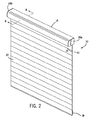
図1〜図5を参照すると、建築物の開口部のための後退可能な覆い10が提供される。後退可能な覆い10は、ヘッドレール14、第1のボトムレール18、第2のボトムレール20、第1のシェード22、及び第2のシェード24を含むことができる。第1のシェード22は、ヘッドレール14と第1のボトムレール18との間に延びることができる。第2のシェード24は、ヘッドレール14と第2のボトムレール20との間に延びることができる。ヘッドレール14は、仕上がった外観を提供するためにヘッドレール14の端を封じることができる2つの対向する端キャップ26a、26bを含むことができる。第1のボトムレール18は、第1のシェード22の下縁に沿って水平方向に延びることができ、第1のシェード22を張った状態に維持するべくバラストとして機能することができる。第2のボトムレール20は、第2のシェード24の下縁に沿って水平方向に延びることができ、第2のシェード24を張った状態に維持するべくバラストとして機能することができる。   1-5, a retractable covering 10 for a building opening is provided. The retractable cover 10 can include a head rail 14, a first bottom rail 18, a second bottom rail 20, a first shade 22, and a second shade 24. The first shade 22 can extend between the head rail 14 and the first bottom rail 18. The second shade 24 can extend between the head rail 14 and the second bottom rail 20. The headrail 14 can include two opposing end caps 26a, 26b that can seal the ends of the headrail 14 to provide a finished appearance. The first bottom rail 18 can extend horizontally along the lower edge of the first shade 22 and can function as a ballast to maintain the first shade 22 in tension. The second bottom rail 20 can extend horizontally along the lower edge of the second shade 24 and can function as a ballast to keep the second shade 24 stretched.

第1のシェード22は、可撓性材料(シーヤーなど)の垂直に吊るされる前側シート30及び後側シート34と、複数の、水平方向に延びる、垂直方向に間隔をおいて配置される可撓性のベーン38とを含むことができる。各ベーン38は、その前縁が前側シート30に取り付けられ、その後縁が後側シート34に取り付けられる状態で、水平な取付ラインに沿って固定することができる。シート30、34とベーン38は、複数の、細長い、垂直方向に一列に並ぶ、長手方向に延びるセルを形成することができ、これは総じて、セルラーパネルと言ってもよい。シート30、34及び/又はベーン38は、連続したいくつかの長さの材料で構築されてもよく、あるいは、縁と縁で互いに取り付けられる又は接合される、重なり合う、又は他の適切な関係性の材料のストリップで構築されてもよい。第2のシェード24は、単一のパネルであってもよく、あるいは、縁と縁で互いに取り付けられる又は接合される、重なり合う、又は他の適切な関係性の材料のストリップで構築されてもよい。   The first shade 22 has a plurality of horizontally extending, vertically spaced flexible, front and rear sheets 30 and 34 that are vertically suspended from a flexible material (such as a sealer). Sex vanes 38 can be included. Each vane 38 can be fixed along a horizontal attachment line with its leading edge attached to the front seat 30 and its trailing edge attached to the rear seat 34. Sheets 30, 34 and vanes 38 may form a plurality of elongated, vertically aligned, longitudinally extending cells, generally referred to as a cellular panel. The sheets 30, 34 and / or vanes 38 may be constructed of several consecutive lengths of material, or are attached or joined to each other at the edges, overlapping, or other suitable relationship. May be constructed of a strip of material. The second shade 24 may be a single panel, or may be constructed of strips of material that are attached or joined to each other at the edges, overlapping, or other appropriately related materials. .

第1のシェード22及び第2のシェード24は、実質的にどのようなタイプの材料で構築されてもよい。例えば、シェード22、24は、布、ポリマー、及び/又は他の適切な材料を含む天然材料及び/又は合成材料から構築されてもよい。布材料は、織布、不織布、編物、又は他の適切な布の種類を含むことができる。シェード22、24は、任意の適切なレベルの光透過率を有することができる。例えば、第1のシェード22及び第2のシェード24は、関連する部屋に所望の雰囲気又は装飾を提供するために、透明材料、半透明材料、及び/又は不透明材料で構築されてもよい。或る例では、第1のシェード22は、透明及び/又は半透明なシート30、34と、半透明及び/又は不透明なベーン38を含む。或る例では、第2のシェード24は、しばしば暗幕(black−out)シェードと呼ばれるゼロの光透過率を有する単一の材料シートで作製される。第2のシェード24は、第2のシェード24が第1のシェード22の後ろで延長されるときに第2のシェード24がそれ自体で第1のシェード22とは異なる美的外観を生み出すように、パターン又はデザインを含むことができる。   The first shade 22 and the second shade 24 may be constructed of substantially any type of material. For example, the shades 22, 24 may be constructed from natural and / or synthetic materials including fabrics, polymers, and / or other suitable materials. The fabric material can include woven fabrics, nonwoven fabrics, knitted fabrics, or other suitable fabric types. The shades 22, 24 can have any suitable level of light transmission. For example, the first shade 22 and the second shade 24 may be constructed of a transparent material, a translucent material, and / or an opaque material to provide a desired atmosphere or decoration for the associated room. In one example, the first shade 22 includes transparent and / or translucent sheets 30, 34 and translucent and / or opaque vanes 38. In one example, the second shade 24 is made of a single sheet of material having zero light transmission, often referred to as a black-out shade. The second shade 24 is such that when the second shade 24 is extended behind the first shade 22, the second shade 24 itself produces an aesthetic appearance that is different from the first shade 22. A pattern or design can be included.

図1〜図6を参照すると、覆い10は、第1のシェード22、第2のシェード24、又はこの両方を上昇又は後退させるように構成された駆動機構又は動作機構40を含むことができる。動作機構40は、機械的に及び/又は電気的に制御されてもよい。動作機構40は、シェード22、24の延長を制御又は調整する若しくはシェード22、24の速度を低下させるために調速装置を含むことができる。   With reference to FIGS. 1-6, the cover 10 may include a drive or operating mechanism 40 configured to raise or retract the first shade 22, the second shade 24, or both. The operating mechanism 40 may be mechanically and / or electrically controlled. The operating mechanism 40 can include a speed governor to control or adjust the extension of the shades 22, 24 or reduce the speed of the shades 22, 24.

或る例では、動作機構40は、ユーザが第1のシェード22及び/又は第2のシェード24を延長する又は後退させることを可能にするために、動作要素42(ボールチェーン、コード、又は杖など)を含むことができる。シェード22、24を動かすために、オペレータが動作要素42を操作することができる。例えば、シェード22、24を延長位置から上昇又は後退させるために、オペレータは動作要素40を下方に引くことができる。シェード22、24を後退位置から延長する又は下降させるために、オペレータは、ブレーキを解放して重力の影響下でシェード22、24が自動的に下降することができるようにするべく動作要素42を操作することができる。   In one example, the motion mechanism 40 may be a motion element 42 (ball chain, cord, or cane) to allow a user to extend or retract the first shade 22 and / or the second shade 24. Etc.). In order to move the shades 22, 24, an operator can operate the operating element 42. For example, the operator can pull the operating element 40 downward to raise or retract the shades 22, 24 from the extended position. In order to extend or lower the shades 22, 24 from the retracted position, the operator releases the brake so that the operating elements 42 can be automatically lowered under the influence of gravity. Can be operated.

加えて又は代替的に、動作機構40は、延長又は後退コマンドを受信するとシェード22、24を延長する又は後退させるように構成された電気モータ44を含むことができる。モータ44は、ユーザがモータ44、したがってシェード22、24の延長及び後退を制御できるようにするために、スイッチに配線接続されてもよく、及び/又は、遠隔制御ユニット46などの送信器と通信するように動作可能な受信器に動作可能に結合されてもよい。モータ44は、モータの介入なしに重力でシェード22、24が下降し、これにより電力消費を低減することができるように、重力下降モードを含むことができる。   In addition or alternatively, the operating mechanism 40 can include an electric motor 44 configured to extend or retract the shades 22, 24 upon receipt of an extend or retract command. The motor 44 may be wired to a switch and / or communicate with a transmitter, such as the remote control unit 46, to allow the user to control the extension and retraction of the motor 44 and thus the shades 22, 24. May be operatively coupled to a receiver operable to. The motor 44 can include a gravity lowering mode so that the shades 22, 24 can be lowered by gravity without motor intervention, thereby reducing power consumption.

図6を参照すると、覆い10は、ヘッドレール14内に配置されてもよいデュアルローラユニット46を含むことができる。デュアルローラユニット46は、内側ローラ48と外側ローラ50を含むことができる。内側ローラ48は外側ローラ50の内部に位置付けることができ、ローラ48、50は、同じ回転軸52を中心として同軸に位置合わせすることができる。ローラ48、50は、内側ローラ48の中心軸を中心として同軸であってもよい。   With reference to FIG. 6, the cover 10 may include a dual roller unit 46 that may be disposed within the headrail 14. The dual roller unit 46 can include an inner roller 48 and an outer roller 50. The inner roller 48 can be positioned inside the outer roller 50, and the rollers 48, 50 can be coaxially aligned about the same rotational axis 52. The rollers 48 and 50 may be coaxial with the central axis of the inner roller 48 as the center.

図6及び図7を参照すると、内側ローラ48は、概して円筒形の形状であってもよく、チューブとして形成されてもよい。第2のシェード24が、接着剤、対応する保持特徴、又は他の適切な取付手段によって上縁で内側ローラ48に取り付けられてもよい。或る例では、長手方向に延びる凹部52が、内側ローラ48の周壁に形成され、第2のシェード24の上縁を内側ローラ48に接着するように構成された接着剤ビードを受け入れることができる。   Referring to FIGS. 6 and 7, the inner roller 48 may be generally cylindrical in shape and may be formed as a tube. The second shade 24 may be attached to the inner roller 48 at the upper edge by adhesive, corresponding retaining features, or other suitable attachment means. In one example, a longitudinally extending recess 52 is formed in the peripheral wall of the inner roller 48 to receive an adhesive bead configured to adhere the upper edge of the second shade 24 to the inner roller 48. .

外側ローラ50は、概して円筒形の形状であってもよく、内側ローラ48を取り囲むことができる。外側ローラ50は、互いに嵌合する2つの部品で形成されてもよい。図6を参照すると、外側ローラ50は、入れ子になる第1のシェル54及び第2のシェル56を含むことができる。図6及び図8〜図11を参照すると、第1のシェル54及び第2のシェル56の長手方向に延びる縁部58、60は、それぞれ、重なり合い、互いに嵌合することができる。第1のシェード22が、接着剤、対応する保持特徴、又は他の適切な取付手段によって上縁で外側ローラ50に取り付けられてもよい。或る例では、一対のチャネル62が、外側ローラ50の周壁に形成され、第1のシェード22の上縁を受け入れ、固定するように構成される。図8〜図11を参照すると、インサート64が、各上縁に形成されたヘムに入れられてもよく、上縁をそれぞれのチャネル62内に保持するように作用することができる。   Outer roller 50 may be generally cylindrical in shape and may surround inner roller 48. The outer roller 50 may be formed of two parts that fit together. Referring to FIG. 6, the outer roller 50 can include a first shell 54 and a second shell 56 that are nested. Referring to FIGS. 6 and 8-11, the longitudinally extending edges 58, 60 of the first shell 54 and the second shell 56 can overlap and fit together. The first shade 22 may be attached to the outer roller 50 at the upper edge by an adhesive, corresponding retaining features, or other suitable attachment means. In one example, a pair of channels 62 are formed in the peripheral wall of the outer roller 50 and are configured to receive and secure the upper edge of the first shade 22. With reference to FIGS. 8-11, an insert 64 may be placed in a hem formed at each upper edge and may act to hold the upper edge within a respective channel 62.

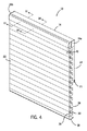
図7を参照すると、内側ローラ48及び外側ローラ50は、右端キャップ26aと左端キャップ26bとの間の距離全体に実質的に延びることができる。内側ローラ48及び外側ローラ50は、同じ又は実質的に同じ長さを有することができる。第1のシェード22及び第2のシェード24は、同じ又は実質的に同じ幅を有することができ、これはローラ48、50の長さに等しくてもよい。或る例では、第1のシェード22及び第2のシェード24は、内側ローラ48及び外側ローラ50の長さと合致する等しい幅を有し、これは、シェード22、24の縁と建築物の開口部の側部との間の光の隙間の存在をなくすことができる。   Referring to FIG. 7, the inner roller 48 and the outer roller 50 can extend substantially the entire distance between the right end cap 26a and the left end cap 26b. Inner roller 48 and outer roller 50 may have the same or substantially the same length. The first shade 22 and the second shade 24 may have the same or substantially the same width, which may be equal to the length of the rollers 48, 50. In one example, the first shade 22 and the second shade 24 have equal widths that match the length of the inner roller 48 and the outer roller 50, which are the edges of the shades 22, 24 and the opening of the building. It is possible to eliminate the presence of a light gap between the side portions of the portion.

図6及び図7を参照すると、デュアルローラユニット50は、対向する端キャップ26a、26bによって回転可能に支持されてもよい。動作機構40は、右端キャップ26aに取り付けられてもよく、例えば、動作要素42又は遠隔制御ユニット46によって作動されてもよい。動作機構40は、内側ローラ48を回転させるべく内側ローラ48と動作可能に関連付けられてもよい。動作機構40は内部フィッティング64を含むことができ、これは、内側ローラ48内に受け入れられてもよく、内側ローラ48の壁とぴったりと係合することができる。内部フィッティング64は、モータ44などの動作機構40によって回転駆動されてもよく、したがって、内側ローラ48を回転駆動することができる。動作機構40は、窓を覆う用途でしばしば用いられる遊星歯車駆動装置を含むことができる。   Referring to FIGS. 6 and 7, the dual roller unit 50 may be rotatably supported by opposing end caps 26a and 26b. The operating mechanism 40 may be attached to the right end cap 26a and may be actuated by, for example, the operating element 42 or the remote control unit 46. The operating mechanism 40 may be operatively associated with the inner roller 48 to rotate the inner roller 48. The operating mechanism 40 can include an internal fitting 64 that can be received within the inner roller 48 and can be snugly engaged with the wall of the inner roller 48. The internal fitting 64 may be rotationally driven by an operating mechanism 40 such as a motor 44, and therefore the inner roller 48 can be rotationally driven. The operating mechanism 40 may include a planetary gear drive that is often used in window covering applications.

図6及び図7を続けると、制限ねじ66が、内側ローラ48の内部に位置付けられてもよく、かつ、制限ねじ66が回転しないように左端キャップ26bに固定されてもよい。制限ナット68が、制限ねじ66とねじ式に係合されてもよく、内側ローラ48の壁に回転によりキー式に取り付けられてもよい。キー構造体は、内側ローラ48の長さに沿った制限ナット68の移動を可能にし得る。内側ローラ48が回転する際に、制限ナット68は、ねじ込まれた制限ねじ66に沿って移動することができ、第2のシェード24の最下延長位置(図5参照)を画定するべく制限ねじ66上に形成された制限止め部と係合することができる。加えて又は代替的に、望まれる場合には制限ねじ66上に上側制限止め部が採用されてもよい。   Continuing with FIGS. 6 and 7, the limit screw 66 may be positioned inside the inner roller 48 and may be secured to the left end cap 26b so that the limit screw 66 does not rotate. A limiting nut 68 may be threadedly engaged with the limiting screw 66 and may be keyed to the wall of the inner roller 48 by rotation. The key structure may allow movement of the limiting nut 68 along the length of the inner roller 48. As the inner roller 48 rotates, the limit nut 68 can move along the threaded limit screw 66 and limit screw to define the lowest extended position of the second shade 24 (see FIG. 5). It is possible to engage with a limit stop formed on 66. Additionally or alternatively, an upper limit stop may be employed on the limit screw 66 if desired.

図6を参照すると、右ブッシング70a及び左ブッシング70bが、内側ローラ48と軸方向に位置合わせされてもよく、内側ローラ48の対向する端に隣接して配置されてもよい。右ブッシング70aは、動作機構40上に回転可能に設置されてもよく、左ブッシング70bは、制限ねじ66上に回転可能に設置されてもよい。ブッシング70a、70bは、シェル54、56間の所望の空間的関係を維持するために外側ローラ50の端にロックしてもよい。ブッシング70a、70bは、それぞれ、一対の軸方向の突起72a、72bを含むことができる。一方の突起72aは第1のシェル54と係合することができ、他方の突起72bは第2のシェル56と係合することができる。ブッシング70a、70bが外側ローラ50の対向する端と係合されるときに、ブッシング70a、70bと外側ローラ50は、内側ローラ48及び外側ローラ50の回転軸52を中心として一緒に回転してもよい。   Referring to FIG. 6, the right bushing 70 a and the left bushing 70 b may be axially aligned with the inner roller 48 and may be disposed adjacent to opposite ends of the inner roller 48. The right bushing 70a may be rotatably installed on the operation mechanism 40, and the left bushing 70b may be rotatably installed on the limit screw 66. Bushings 70a, 70b may lock to the end of outer roller 50 to maintain the desired spatial relationship between shells 54,56. The bushings 70a, 70b can each include a pair of axial protrusions 72a, 72b. One protrusion 72 a can engage with the first shell 54, and the other protrusion 72 b can engage with the second shell 56. When the bushings 70a, 70b are engaged with the opposite ends of the outer roller 50, the bushings 70a, 70b and the outer roller 50 may rotate together about the inner roller 48 and the rotation axis 52 of the outer roller 50. Good.

図8〜図11を参照すると、外側ローラ50の第1のシェル54及び第2のシェル56は、それぞれ、ブッシング70a、70bの軸方向の突起72a、72bをすっぽり受け入れる保持特徴を画定することができる。保持特徴は、外側ローラ50から外側ローラ50によって画定される内部空間に内向きに延びる、周方向に離間して配置されるシェルフ74として形成されてもよい。ブッシング70a、70bが外側ローラ50の端と係合されるときに、軸方向の突起72a、72bは、第1のシェル54と第2のシェル56との間の相対運動を防ぐべくシェルフ74と外側ローラ50の周壁との間にすっぽり受け入れられてもよい。   With reference to FIGS. 8-11, the first shell 54 and the second shell 56 of the outer roller 50 may define retention features that entirely receive the axial protrusions 72a, 72b of the bushings 70a, 70b, respectively. it can. The retention feature may be formed as a circumferentially spaced shelf 74 that extends inwardly from the outer roller 50 to an interior space defined by the outer roller 50. When the bushings 70a, 70b are engaged with the ends of the outer roller 50, the axial protrusions 72a, 72b are in contact with the shelf 74 to prevent relative movement between the first shell 54 and the second shell 56. It may be completely received between the peripheral wall of the outer roller 50.

図8〜図11を続けると、第1のシェル54及び第2のシェル56は、外側ローラ50の長さに沿って延び、かつ、外側ローラ50の内部と連通する、スロット76を画定することができる。スロット76は、第2のシェード24の延長及び後退中に第2のシェード24の通過を可能にする。第1のシェル54及び第2のシェル56の第1の端部58、60がそれぞれ互いに嵌合されるときに、第1のシェル54及び第2のシェル56の第2の長手方向に延びる縁部78、80は、スロット76を画定するべく互いから周方向に離間されていてもよい。第1のシェル54及び第2のシェル56の対立する第2の縁部78、80は、第2のシェード24の通過を可能にしつつ、第2のシェード24のボトムレール20の通過は防ぐのに十分な距離だけ互いから離間されていてもよい。ブッシング70a、70bの軸方向の突起72a、72bは、覆い10の動作中にスロット76の幅を維持することができる。スロット76は、第1のシェード22がその延長された、ベーンが開いた構成にあるときにチャネル62の対の最後部の上に及びこれに隣接して存在するように外側ローラ50上に位置付けられてもよい。   Continuing with FIGS. 8-11, the first shell 54 and the second shell 56 define a slot 76 that extends along the length of the outer roller 50 and communicates with the interior of the outer roller 50. Can do. The slot 76 allows passage of the second shade 24 during extension and retraction of the second shade 24. Edges extending in the second longitudinal direction of the first shell 54 and the second shell 56 when the first ends 58, 60 of the first shell 54 and the second shell 56 are respectively fitted together. The portions 78, 80 may be circumferentially spaced from each other to define the slot 76. The opposing second edges 78, 80 of the first shell 54 and the second shell 56 allow passage of the second shade 24 while preventing passage of the bottom rail 20 of the second shade 24. May be separated from each other by a sufficient distance. The axial projections 72a, 72b of the bushings 70a, 70b can maintain the width of the slot 76 during operation of the cover 10. The slot 76 is positioned on the outer roller 50 so that the first shade 22 is on and adjacent to the end of the pair of channels 62 when the extended vane is in its open configuration. May be.

図8〜図11を引き続き参照すると、外側ローラ50は、スロット76の両側の周壁に凹型の座部81を画定することができる。座部81は、スロット76の長さに沿って延びる凹部として形成されてもよい。座部81は、外側ローラ50の対向する縁部78、80によって形成されたスロット76にわたる概して垂直に配向されるベース壁84を含むことができる。座部81は、第2のシェード24が十分に後退された位置にあるときに第2のボトムレール20を受け入れるように構成されてもよい(図8参照)。ベース壁84は、第2のボトムレール20と外側ローラ50との間の比較的垂直な接線方向の係合及び係合解除を可能にすることができる。スロット76及び座部81は、第1のシェード22の後側シート34の取付点62よりも上の外側ローラ50の周縁上に位置付けられてもよく、スロット76及び座部81の位置は、図9〜図11では3時と言ってもよい。外側ローラ50の周縁上の最遠の後方位置付近の座部81及びスロット76の場所は、座部81の形状と共に、第2のボトムレール20が後退中に垂直に引き上げられて座部81に入る際の第2のボトムレール20の確実な受け入れを可能にすることができる(図8〜図10参照)。   With continued reference to FIGS. 8-11, the outer roller 50 can define concave seats 81 on the peripheral walls on either side of the slot 76. The seat 81 may be formed as a recess that extends along the length of the slot 76. The seat 81 can include a base wall 84 that is generally vertically oriented across a slot 76 formed by opposing edges 78, 80 of the outer roller 50. The seat 81 may be configured to receive the second bottom rail 20 when the second shade 24 is in a fully retracted position (see FIG. 8). Base wall 84 may allow for a relatively vertical tangential engagement and disengagement between second bottom rail 20 and outer roller 50. The slot 76 and the seat 81 may be positioned on the periphery of the outer roller 50 above the attachment point 62 of the rear sheet 34 of the first shade 22, and the positions of the slot 76 and the seat 81 are illustrated in FIG. 9 to 11 may be 3 o'clock. The location of the seat 81 and the slot 76 near the farthest rear position on the periphery of the outer roller 50, together with the shape of the seat 81, is pulled up vertically while the second bottom rail 20 is retracted to the seat 81. It is possible to reliably receive the second bottom rail 20 when entering (see FIGS. 8 to 10).

座部81の形状及び外側ローラ50上のその配向は、第2のシェード24の延長を開始するために座部81からの第2のボトムレール20の円滑な予測可能な係合解除を促進することができる。座部81の形状及び配向は、ボトムレール20が座部81から垂直に落下することを可能にすることができ、これは比較的重いボトムレール20への重力を利用する。外側ローラ50上の座部81の概して接線方向の配向がその一助となることができる。スロット76の下側自由縁(外側ローラ50の第2のシェル56の縁部80によって画定される)は、第2のシェード24がスロット76を通して延長及び後退される際の縁部80の上の第2のシェード24の円滑な移動を可能にするべく湾曲していても又は丸みをつけられていてもよい。   The shape of the seat 81 and its orientation on the outer roller 50 facilitates a smooth and predictable disengagement of the second bottom rail 20 from the seat 81 to initiate the extension of the second shade 24. be able to. The shape and orientation of the seat 81 can allow the bottom rail 20 to fall vertically from the seat 81, which takes advantage of gravity on the relatively heavy bottom rail 20. The generally tangential orientation of the seat 81 on the outer roller 50 can help. The lower free edge of the slot 76 (defined by the edge 80 of the second shell 56 of the outer roller 50) is above the edge 80 as the second shade 24 is extended and retracted through the slot 76. It may be curved or rounded to allow smooth movement of the second shade 24.

第2のボトムレール20は、比較的高い質量を有し、かつ、第2のシェード24の下縁を受け入れ、保持するためにその長さに沿って延びる溝を画定する、細長い部材であってもよい。第2のシェード24の下縁は、第2のシェード24の下縁に形成されたヘムに入れられるインサート82によってボトムレール20の溝に保持されてもよい。第2のボトムレール20の外形の一部は、第2のシェード24が後退位置にあるときに外側ローラ50に形成された座部81の形状に適合するべくその形状に概して合致することができる。   The second bottom rail 20 is an elongate member having a relatively high mass and defining a groove extending along its length to receive and hold the lower edge of the second shade 24. Also good. The lower edge of the second shade 24 may be held in the groove of the bottom rail 20 by an insert 82 that is placed in a hem formed on the lower edge of the second shade 24. A portion of the outer shape of the second bottom rail 20 can generally match its shape to match the shape of the seat 81 formed on the outer roller 50 when the second shade 24 is in the retracted position. .

図7〜図11を参照すると、第1のシェード22は、外側ローラ50に結合され、これに巻きつけ可能であってもよい。前側シート30及び後側シート34のそれぞれの上縁は、周方向に離間された場所で外側ローラ50に取り付けられてもよい。第1のシェード22は、外側ローラ50の後側に巻きつけられ又はそこから繰り出されてもよく、この場合、ローラ50の後側は、ローラ50の前側と関連する建築物の開口部の道路側との間に位置付けられる(図8〜図11では、ローラ50の後側は右である)。一般に、外側ローラ50の第1の方向(図8〜図11では反時計回り)の回転が、第1のシェード22を外側ローラ50に巻きつけることによって第1のシェード22を関連する建築物の開口部の1つ以上の側部(上側など)に隣接する位置に後退させ、外側ローラ50の第2の反対方向の回転が、第1のシェード22を開口部にわたって(例えば下側に)延長させる。   Referring to FIGS. 7 to 11, the first shade 22 may be coupled to and wound around the outer roller 50. The upper edges of each of the front sheet 30 and the rear sheet 34 may be attached to the outer roller 50 at locations spaced apart in the circumferential direction. The first shade 22 may be wrapped around or fed out from the rear side of the outer roller 50, where the rear side of the roller 50 is the road of the building opening associated with the front side of the roller 50. (In FIGS. 8 to 11, the rear side of the roller 50 is right). Generally, rotation of the outer roller 50 in a first direction (counterclockwise in FIGS. 8-11) causes the first shade 22 to be associated with the associated building by wrapping the first shade 22 around the outer roller 50. Retracting to a position adjacent to one or more sides of the opening (such as the upper side), rotation of the outer roller 50 in the second opposite direction extends the first shade 22 over the opening (eg, down). Let

図7〜図11を引き続き参照すると、第2のシェード24は、内側ローラ48に結合され、これに巻きつけ可能であってもよい。第2のシェード24の上縁は、前述のように内側ローラ48に取り付けられてもよい。第2のシェード24は、ローラユニット46の後側に巻きつけられ又はそこから繰り出されてもよく、この場合、ローラユニット46の後側は、ローラユニット46の前側と関連する建築物の開口部の道路側との間に位置付けられる(図8〜図11では、ローラユニット46の後側は右である)。一般に、内側ローラ48の第1の方向(図8〜図11では反時計回り)の回転が、第2のシェード24を内側ローラ48に巻きつけることによって第2のシェード24を関連する建築物の開口部の1つ以上の側部(上側など)に隣接する位置に後退させ、内側ローラ48の第2の反対方向の回転が、第2のシェード24を開口部にわたって(例えば下側に)延長させる。   With continued reference to FIGS. 7-11, the second shade 24 may be coupled to and wound around the inner roller 48. The upper edge of the second shade 24 may be attached to the inner roller 48 as described above. The second shade 24 may be wrapped around or unrolled from the back side of the roller unit 46, where the back side of the roller unit 46 is the opening of the building associated with the front side of the roller unit 46. (The rear side of the roller unit 46 is on the right side in FIGS. 8 to 11). In general, rotation of the inner roller 48 in a first direction (counterclockwise in FIGS. 8-11) causes the second shade 24 to be associated with the associated building by wrapping the second shade 24 around the inner roller 48. Retracting to a position adjacent to one or more sides of the opening (such as the upper side), rotation of the inner roller 48 in the second opposite direction extends the second shade 24 over the opening (eg, down). Let

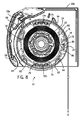
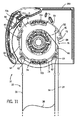
覆いの動作が、図1〜図5及び図7〜図11を参照して以下で説明される。図1及び図7に示すように、第1のシェード22及び第2のシェード24は、十分に後退された位置にあり、ヘッドレール14内に隠れている。この構成(図7参照)では、第2のシェード24が内側ローラ48に十分に巻きつけられ、第1のシェード22が外側ローラ50に十分に巻きつけられる。或る例では、第1のボトムレール18が、上側制限止め部を画定するべくヘッドレール14の一部と係合する。   The covering operation is described below with reference to FIGS. 1 to 5 and 7 to 11. As shown in FIGS. 1 and 7, the first shade 22 and the second shade 24 are in a fully retracted position and are hidden in the head rail 14. In this configuration (see FIG. 7), the second shade 24 is sufficiently wound around the inner roller 48, and the first shade 22 is sufficiently wound around the outer roller 50. In one example, the first bottom rail 18 engages a portion of the head rail 14 to define an upper limit stop.

ヘッドレール14から第1のシェード22を延長するために、ユーザが動作機構40を作動させて内側ローラ48を延長方向(図8〜図11では時計回り)に回転させてもよく、これにより、第1のボトムレール18の重量が第1のシェード22に下向きの力をかけることに少なくとも部分的に起因して、外側ローラ50が延長方向(図8〜図11では時計回り)に回転する。第1のシェード22が外側ローラ50の後側から延長される際に、外側ローラ50が内側ローラ48と概して一緒に回転する。デュアルローラユニット46は、ユーザが内側ローラ48を回転するように制御する方向に概して回転する。   In order to extend the first shade 22 from the head rail 14, the user may operate the operating mechanism 40 to rotate the inner roller 48 in the extending direction (clockwise in FIGS. 8 to 11). The outer roller 50 rotates in the extending direction (clockwise in FIGS. 8 to 11) due at least in part to the weight of the first bottom rail 18 applying a downward force on the first shade 22. As the first shade 22 is extended from the rear side of the outer roller 50, the outer roller 50 rotates generally together with the inner roller 48. The dual roller unit 46 generally rotates in a direction that controls the user to rotate the inner roller 48.

図2及び図8を参照すると、第1のシェード22が閉じた又は畳まれた構成で外側ローラ50の後側から延長され、この場合、前側シート30と後側シート34は互いに比較的近く、ベーン38は前側シート30及び後側シート34とほぼ同一平面の隣接した関係性で垂直方向に延びる。第1のシェード22が外側ローラ50から実質的に繰り出されると、外側ローラ50の延長方向の継続した回転が、前側シート30と後側シート34を相互に概して垂直方向に動かして、ベーン38を閉位置(図2及び図8)から開位置(図3及び図9)にシフトさせる。第1のボトムレール18の後部は、ベーン38の全開を容易にするためにボトムレール18の前部よりも重くされてもよい。   2 and 8, the first shade 22 is extended from the rear side of the outer roller 50 in a closed or folded configuration, where the front sheet 30 and the rear sheet 34 are relatively close to each other, The vane 38 extends in the vertical direction in an adjacent relationship that is substantially coplanar with the front seat 30 and the rear seat 34. When the first shade 22 is substantially unwound from the outer roller 50, continued rotation of the outer roller 50 in the extending direction causes the front sheet 30 and the rear sheet 34 to move in a generally vertical direction relative to each other, causing the vane 38 to move. Shift from the closed position (FIGS. 2 and 8) to the open position (FIGS. 3 and 9). The rear portion of the first bottom rail 18 may be heavier than the front portion of the bottom rail 18 to facilitate the full opening of the vane 38.

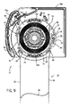
図3及び図9を参照すると、第1のシェード24が十分に延長された位置にあり、ベーン38が開いた又は広がった構成にある、覆い10が示される。この位置では、前側シート30と後側シート34は水平方向に離間され、それらの間にベーン38が実質的に水平方向に延びており、外側ローラ50との前側シート30及び後側シート34の取付点62は同じ高さに配置される場合がある。図9では、例えば、取付点62の位置は、4時と8時と言ってもよく、互いに実質的に同じ高さに配置される。図9に示された位置からの外側ローラ50のいずれかの方向の回転が、前側シート30と後側シート34を互いに向けて動かし、ベーン38をより垂直なアラインメントに再配向する。   Referring to FIGS. 3 and 9, the covering 10 is shown with the first shade 24 in a fully extended position and the vane 38 in an open or unfolded configuration. In this position, the front sheet 30 and the rear sheet 34 are spaced apart in the horizontal direction, and a vane 38 extends substantially horizontally therebetween, so that the front sheet 30 and the rear sheet 34 with the outer roller 50 are in contact with each other. The attachment points 62 may be arranged at the same height. In FIG. 9, for example, the position of the attachment point 62 may be 4 o'clock and 8 o'clock, and they are arranged at substantially the same height. Rotation in either direction of the outer roller 50 from the position shown in FIG. 9 moves the front sheet 30 and the rear sheet 34 towards each other, reorienting the vanes 38 to a more vertical alignment.

第1のシェード22が外側ローラ50から十分に繰り出されるときに、外側ローラ50のスロット76は、内側ローラ48が延長方向にさらに回転すると第2のシェード24のボトムレール20が座部81から垂直に落下できるようにヘッドレール14内で回転して配向される。比較的垂直なベース壁84を備える座部81の概して接線方向の配向及び概して垂直な位置付け(図10及び図11参照)により、内側ローラ48の延長方向の継続した回転に起因して第2のシェード24の張力が減少するときに、第2のボトムレール20の重量でボトムレール20を外側ローラ50から着座解除することが可能となる。動作機構40は、第2のシェード24の、したがって第1のシェード22の望ましくない下方移動を制約するために内側ローラ48に動作可能に結合されるブレーキシステムを含むことができる。   When the first shade 22 is fully unwound from the outer roller 50, the slot 76 of the outer roller 50 causes the bottom rail 20 of the second shade 24 to be perpendicular to the seat 81 when the inner roller 48 further rotates in the extending direction. It is rotated and oriented in the head rail 14 so that it can fall. Due to the generally tangential orientation and generally vertical positioning of the seat 81 with the relatively vertical base wall 84 (see FIGS. 10 and 11), the second due to continued rotation of the inner roller 48 in the extending direction. When the tension of the shade 24 decreases, the bottom rail 20 can be released from the outer roller 50 by the weight of the second bottom rail 20. The actuation mechanism 40 may include a brake system that is operatively coupled to the inner roller 48 to constrain undesired downward movement of the second shade 24 and thus the first shade 22.

第2のシェード24を延長するために、内側ローラ48を延長方向に回転させるべくユーザによって動作機構40がさらに作動される。第2のシェード24の延長中に(図4及び図10参照)、外側ローラ50と第1のシェード22は第1のシェード22の重量に起因して静止したままであってもよく、第1のボトムレール18の重量が、積極的なロックなしに外側ローラ50の回転位置を維持する。或る例では、後述するように、第1のシェード22のフル延長時の外側ローラ50の回転を防ぐために積極的なロックが用いられてもよい。図10及び図11に示すように、第2のシェード24の延長中に、外側ローラ50に画定されたスロット76は、後方に誘導される場合があり、内側ローラ48及び外側ローラ50の回転軸52(図6参照)と実質的に水平方向に位置合わせされる場合がある。言い換えれば、第2のシェード24が内側ローラ48及び外側ローラ50の後側で外れることができる。   To extend the second shade 24, the operating mechanism 40 is further activated by the user to rotate the inner roller 48 in the extending direction. During the extension of the second shade 24 (see FIGS. 4 and 10), the outer roller 50 and the first shade 22 may remain stationary due to the weight of the first shade 22, The weight of the bottom rail 18 maintains the rotational position of the outer roller 50 without aggressive locking. In some examples, as described below, a positive lock may be used to prevent rotation of the outer roller 50 when the first shade 22 is fully extended. As shown in FIGS. 10 and 11, during the extension of the second shade 24, the slot 76 defined in the outer roller 50 may be guided rearward and the rotation axis of the inner roller 48 and the outer roller 50. 52 (see FIG. 6) may be aligned substantially horizontally. In other words, the second shade 24 can be detached behind the inner roller 48 and the outer roller 50.

第2のシェード24の延長中に、内側ローラ48は、フィッティング64及び制限ナット68を内側ローラ48のそれぞれの端で支持している状態で、外側ローラ50に対して回転する。内側ローラ48が延長方向に回転する際に、第2のシェード48が、外側ローラ50に形成されたスロット76を通して延長される際に内側ローラ48から繰り出される。内側ローラ48の延長方向の回転が、制限ナット68を制限ねじ66に沿って下側制限止め部の方に動かす。   During extension of the second shade 24, the inner roller 48 rotates relative to the outer roller 50 with a fitting 64 and a limiting nut 68 supported at each end of the inner roller 48. As the inner roller 48 rotates in the extending direction, the second shade 48 is unwound from the inner roller 48 as it extends through a slot 76 formed in the outer roller 50. Rotational rotation of the inner roller 48 moves the limiting nut 68 along the limiting screw 66 toward the lower limiting stop.

図5及び図11を参照すると、第1のシェード22と第2のシェード24との両方が十分に延長された位置にあり、ベーン38が開いた又は広がった構成にある、覆い10が示される。この位置では、前側シート30と後側シート34は水平方向に離間され、それらの間にベーン38が実質的に水平方向に延びている。第2のシェード24は、暗幕シェードであってもよく、光が第2のシェード24、したがって第1のシェード22を通過するのを抑制する。第2のシェード24が十分に延長されるときに(図5及び図11参照)、第2のシェード24は、第1のシェード22から後方にオフセットされてもよいが、第1のシェード22と長さ及び幅において同延に延びることができる。第1のシェード22を通過する光の量を制御するために、第2のシェード24がヘッドレール14に引き込まれ、デュアルローラユニット46の内側ローラ48に巻きつけられてもよい。   Referring to FIGS. 5 and 11, the covering 10 is shown with both the first shade 22 and the second shade 24 in a fully extended position and the vane 38 in an open or unfolded configuration. . In this position, the front seat 30 and the rear seat 34 are horizontally spaced, with a vane 38 extending substantially horizontally therebetween. The second shade 24 may be a blackout shade and suppresses light from passing through the second shade 24, and thus the first shade 22. When the second shade 24 is sufficiently extended (see FIGS. 5 and 11), the second shade 24 may be offset backward from the first shade 22, but the first shade 22 and It can extend in length and width. In order to control the amount of light passing through the first shade 22, the second shade 24 may be drawn into the head rail 14 and wound around the inner rollers 48 of the dual roller unit 46.

第2のシェード24が十分に延長された(最下延長)位置にあるときに、制限ナット68は、内側ローラ48のさらなる回転を防ぐために制限ねじ66上に形成された下側限界止め部と係合する状態で制限ねじ66(図6参照)上に位置付けられてもよい。制限ねじ66は、覆い10の上側限界を画定するべく上側限界止め部も含むことができる。代替的に、第1のシェード22が十分に後退されるときに、第1のシェード22のボトムレール18が覆い10の上側限界止め部として役立つようにヘッドレール14の一部と係合してもよい。   When the second shade 24 is in the fully extended (bottom extended) position, the limit nut 68 includes a lower limit stop formed on the limit screw 66 to prevent further rotation of the inner roller 48. It may be positioned on the limiting screw 66 (see FIG. 6) in the engaged state. The limiting screw 66 can also include an upper limit stop to define the upper limit of the cover 10. Alternatively, when the first shade 22 is fully retracted, the bottom rail 18 of the first shade 22 engages a portion of the head rail 14 to serve as the upper limit stop for the cover 10. Also good.

延長プロセス中の任意の時点で、ユーザは、動作機構40を止めてもよく、又は第1のシェード22及び第2のシェード24を所望の位置に動かすために動作機構40の方向を逆にしてもよい。電動の覆い10を含む例では、モータ44を制御する、したがって第1のシェード22及び第2のシェード24の位置を制御するのに予めプログラムされたコマンドが用いられてもよい。コマンドは、第1のシェード22及び第2のシェード24を、第1のシェード22及び第2のシェード24が十分に後退される第1の位置、第1のシェード22が十分に延長され、第2のシェード24が十分に後退される第2の位置、及び第1のシェード22及び第2のシェード24が十分に延長される第3の位置などの所定のシェード位置に動かすようにモータ44に命令してもよい。コマンドは、遠隔制御ユニット46によってモータ44に伝送されてもよい。   At any point during the extension process, the user may stop the operating mechanism 40 or reverse the direction of the operating mechanism 40 to move the first shade 22 and the second shade 24 to the desired position. Also good. In an example that includes a motorized shroud 10, preprogrammed commands may be used to control the motor 44 and thus control the position of the first shade 22 and the second shade 24. The command is such that the first shade 22 and the second shade 24 are moved to the first position where the first shade 22 and the second shade 24 are sufficiently retracted, the first shade 22 is sufficiently extended, The motor 44 is moved to a predetermined shade position, such as a second position in which the second shade 24 is fully retracted and a third position in which the first shade 22 and the second shade 24 are sufficiently extended. You may order. The command may be transmitted to the motor 44 by the remote control unit 46.

第1のシェード22及び第2のシェード24の後退は、例えば概して図11〜図8に従う前述の延長手順と比べて逆の順序で達成されてもよい。図5及び図11では、第1のシェード22及び第2のシェード24は、十分に延長された位置に配置される。第1のシェード22と第2のシェード24との両方が十分に延長された位置にあるときに、制限ナット68(図6参照)が、制限ねじ66上に形成されてもよい下側限界止め部と係合されてもよい。この位置からの動作要素42及び/又はモータ44などによる動作機構40の作動が制限ナット68を下側限界止め部から軸方向に遠くに動かし、覆い10の後退プロセスを開始する。後退プロセスは、一般に、動作機構40を作動させて、最初に内側ローラ48を後退方向(図11では反時計回り)に回転させて第2のシェード24を後退させ、第2のシェード24が十分に後退されるときに第1のシェード22を外側ローラ50上に後退させるべく外側ローラ50を後退方向(図11では反時計回り)に回転させることに関係する。この手順はさらに後述される。   Retraction of the first shade 22 and the second shade 24 may be accomplished in the reverse order compared to the extension procedure described above, for example, generally in accordance with FIGS. In FIGS. 5 and 11, the first shade 22 and the second shade 24 are arranged in a sufficiently extended position. A lower limit stop 68 may be formed on the limit screw 66 when a limit nut 68 (see FIG. 6) is present when both the first shade 22 and the second shade 24 are in a fully extended position. May be engaged with the part. Activation of the operating mechanism 40 from this position, such as by the operating element 42 and / or the motor 44, moves the limiting nut 68 axially away from the lower limit stop and initiates the cover 10 retracting process. The retraction process generally involves operating the operating mechanism 40 to first rotate the inner roller 48 in the retraction direction (counterclockwise in FIG. 11) to retract the second shade 24 so that the second shade 24 is sufficient. This is related to rotating the outer roller 50 in the backward direction (counterclockwise in FIG. 11) in order to retract the first shade 22 onto the outer roller 50. This procedure is further described below.

第2のシェード24を図5及び図11の十分に延長された位置から後退させるために、ユーザが動作機構40を作動させて内側ローラ48を後退方向(図8〜図11では反時計回り)に回転させ、これにより、第2のシェード24を内側ローラ48に巻きつけ、第2のボトムレール20を第1のシェード22の後側シート34の後面に沿って上方に上昇させる。第2のシェード24の後退中に、内側ローラ48が、フィッティング64及び制限ナット68を内側ローラ48のそれぞれの端で支持している状態で、外側ローラ50に対して回転する。内側ローラ48が後退方向に回転する際に、第2のシェード24が、外側ローラ50に形成されたスロット76を通して引かれるので内側ローラ48上に巻きつけられる。内側ローラ48の後退方向の回転が、制限ナット68を制限ねじ66に沿って制限ねじ66の反対端の方に動かす。同じく第2のシェード24の後退中に、外側ローラ50の回転を抑制するように外側ローラ50に対して作用する第1のボトムレール18の重量及び外側ローラ50から吊るされた第1のシェード22の一部の重量に起因して、第1のシェード22が十分に延長された開位置にとどまる。これは、ユーザが第1のシェード22の位置又は配向に影響を及ぼさずに第2のシェード24を十分に延長された位置と十分に後退された位置との間で動かすことを可能にする。   In order to retract the second shade 24 from the fully extended position of FIGS. 5 and 11, the user operates the operating mechanism 40 to retract the inner roller 48 (counterclockwise in FIGS. 8-11). Thus, the second shade 24 is wound around the inner roller 48 and the second bottom rail 20 is raised upward along the rear surface of the rear seat 34 of the first shade 22. During retraction of the second shade 24, the inner roller 48 rotates relative to the outer roller 50 with the fitting 64 and the limiting nut 68 supported at each end of the inner roller 48. As the inner roller 48 rotates in the retracted direction, the second shade 24 is drawn through the slot 76 formed in the outer roller 50 and is thus wound around the inner roller 48. The reverse rotation of the inner roller 48 moves the limit nut 68 along the limit screw 66 toward the opposite end of the limit screw 66. Similarly, during the backward movement of the second shade 24, the weight of the first bottom rail 18 acting on the outer roller 50 so as to suppress the rotation of the outer roller 50 and the first shade 22 suspended from the outer roller 50. The first shade 22 remains in the fully extended open position. This allows the user to move the second shade 24 between a fully extended position and a fully retracted position without affecting the position or orientation of the first shade 22.

図9及び図10を参照すると、逆の順序で、第2のシェード24が外側ローラ50にさらに引き込まれる際に、第2のボトムレール20が座部81に確実に位置付けられる。ボトムレール20が外側ローラ50の座部81と係合すると、動作機構40の駆動力が第2のシェード24を通じて外側ローラ50に伝達されてもよい。すなわち、動作機構40は、内側ローラ48に回転力をかけることができ、この回転力は、次に、第2のシェード24の張力下で座部81でのボトムレール20の係合を通じて外側ローラ50にかかる場合がある。図8及び図9を参照すると、第2のシェード24が内側ローラ48上に十分に巻きつけられ、第2のボトムレール20が外側ローラ50の座部81に受け入れられるときに、外側ローラ50は、同じ後退方向の内側ローラ48の回転を通じて動作機構40によって後退方向(図8及び図9では反時計回り)に駆動されてもよい。したがって、ボトムレール20が座部81に受け入れられ、動作機構40によって内側ローラ48に後退力(図8及び図9では反時計回り)がかかるときに、外側ローラ50は、一般に、内側ローラ48と連動して回転する。   Referring to FIGS. 9 and 10, the second bottom rail 20 is reliably positioned on the seat portion 81 when the second shade 24 is further drawn into the outer roller 50 in the reverse order. When the bottom rail 20 is engaged with the seat 81 of the outer roller 50, the driving force of the operation mechanism 40 may be transmitted to the outer roller 50 through the second shade 24. That is, the operating mechanism 40 can apply a rotational force to the inner roller 48, and this rotational force is then applied to the outer roller through the engagement of the bottom rail 20 at the seat 81 under the tension of the second shade 24. May take 50. Referring to FIGS. 8 and 9, when the second shade 24 is fully wound on the inner roller 48 and the second bottom rail 20 is received in the seat 81 of the outer roller 50, the outer roller 50 is The drive mechanism 40 may be driven in the backward direction (counterclockwise in FIGS. 8 and 9) through the rotation of the inner roller 48 in the same backward direction. Accordingly, when the bottom rail 20 is received by the seat portion 81 and the retracting force (counterclockwise in FIGS. 8 and 9) is applied to the inner roller 48 by the operating mechanism 40, the outer roller 50 generally It rotates in conjunction.

図8を参照すると、外側ローラ50が後退方向に回転し続ける際に、第1のシェード22が外側ローラ50の周りに巻きつく。第1のシェード22は、外側ローラ50の周りに巻きつけられる際に、第1のシェード22の吊るされた部分及びボトムレール18の重量に起因して張力下にある。   Referring to FIG. 8, the first shade 22 is wound around the outer roller 50 as the outer roller 50 continues to rotate in the backward direction. As the first shade 22 is wound around the outer roller 50, it is under tension due to the suspended portion of the first shade 22 and the weight of the bottom rail 18.

第1のシェード22が十分に後退されるときに、第1のボトムレール18は、デュアルローラユニット46の上側制限止め部として役立つようにヘッドレール14の一部と係合、例えば当接してもよい。上側後退位置を画定するために、下側制限止め部とは反対の制限ねじ66上に位置付けられれる上側制限止め部を含む他の機構が用いられてもよいと考えられる。例えば、上側制限止め部は、第1のシェード22のフル後退時にナット68が上側制限止め部と係合するように制限ねじ66上に形成され、ねじ66に沿って位置付けられてもよい。   When the first shade 22 is fully retracted, the first bottom rail 18 engages, eg, abuts, a portion of the head rail 14 to serve as the upper limit stop for the dual roller unit 46. Good. It is contemplated that other mechanisms may be used to define an upper retracted position, including an upper limit stop positioned on a limit screw 66 opposite the lower limit stop. For example, the upper limit stop may be formed on the limit screw 66 and positioned along the screw 66 such that the nut 68 engages the upper limit stop when the first shade 22 is fully retracted.

上記の説明のように、十分に延長された位置からの第2のシェード24、次いで第1のシェード22の後退は、ユーザが両方のシェード22、24を後退させるための単一の動作要素42又はモータ44を作動する状態で起こる。制限ねじ66は、制限ナット68が下側制限止め部からねじ66に沿って上側後退位置に到達するまで動くことを可能にするのに十分な長さを含む。第1のシェード22は、外側ローラ42の前側に巻きつけられ又はそこから繰り出されてもよいと考えられる。前側が下降する(front−descending)シェード構造体に適用される場合のデュアルローラシェード技術の実装を容易にするために、本明細書で説明される構造体への付随する修正が必要とされるであろう。   As described above, the retraction of the second shade 24 and then the first shade 22 from the fully extended position is a single operating element 42 for the user to retract both shades 22, 24. Or, it occurs when the motor 44 is operated. The limiting screw 66 includes a length sufficient to allow the limiting nut 68 to move from the lower limiting stop along the screw 66 until reaching the upper retracted position. It is contemplated that the first shade 22 may be wound around or fed out from the front side of the outer roller 42. To facilitate the implementation of dual roller shade technology when applied to a front-descending shade structure, accompanying modifications to the structure described herein are required. Will.

覆いは、第1のシェード22が十分に延長された位置にあるときに外側ローラ50の回転を制約するロック機構を含むことができ、これにより、第1のシェード22は、十分に延長された位置に確実にとどまり、第2のシェード24の延長中に内側ローラ48の回転によって実質的に影響されない。ロック機構は、外側ローラ50の回転を制約する第1の位置と外側ローラ50の回転を可能にする第2の位置との間で移動可能(ピボット運動可能、平行移動可能、又は他の適切な移動など)であってもよい。一例では、ロック機構は、外側ローラ50の外周に沿って長手方向に平行移動し、外側ローラ50の回転を制約するべく止め部と係合する、外側ローラ50の外部に位置付けられるロック部材を含む。別の例では、ロック機構は、外側ローラ50の回転を制約するべくピボットして外側ローラ50と係合する、外側ローラ50の外部に位置付けられるロック部材を含む。   The covering can include a locking mechanism that constrains rotation of the outer roller 50 when the first shade 22 is in a fully extended position, whereby the first shade 22 is fully extended. It stays in position and is substantially unaffected by the rotation of the inner roller 48 during the extension of the second shade 24. The locking mechanism is movable between a first position that constrains rotation of the outer roller 50 and a second position that allows rotation of the outer roller 50 (pivotable, translatable, or other suitable position). Movement). In one example, the locking mechanism includes a locking member positioned outside the outer roller 50 that translates longitudinally along the outer periphery of the outer roller 50 and engages a stop to constrain rotation of the outer roller 50. . In another example, the locking mechanism includes a locking member positioned outside the outer roller 50 that pivots to engage the outer roller 50 to constrain rotation of the outer roller 50.

図12〜図27を参照すると、第1のシェード22のフル延長時に外側ローラの回転を積極的にロックするべくロック機構を用いる建築物の開口部のための覆いが提供される。ロック機構及び保持クリップを除いて、図12〜図27に描画される覆いは、図1〜図11に描画される覆いと概して同じ特徴及び動作を有する。したがって、図1〜図11に描画される覆いの特徴及び動作の上記の説明は、以下の解説で述べられることを除いて、図12〜図27に描画される覆いに概して適用可能と考えられるべきである。図12〜図27で用いられる参照番号は、参照番号が100だけ増加されていることを除いて、同様の部分及び構成要素を反映するべく図1〜図11で用いられる参照番号と概して対応する。   With reference to FIGS. 12-27, a covering is provided for an opening in a building that uses a locking mechanism to positively lock the rotation of the outer roller when the first shade 22 is fully extended. Except for the locking mechanism and the retaining clip, the cover depicted in FIGS. 12-27 generally has the same features and operations as the cover depicted in FIGS. Accordingly, the above description of the features and operation of the cover depicted in FIGS. 1-11 is considered generally applicable to the cover depicted in FIGS. 12-27, except as noted in the following discussion. Should. The reference numbers used in FIGS. 12-27 generally correspond to the reference numbers used in FIGS. 1-11 to reflect similar parts and components, except that the reference numbers have been increased by 100. .

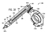
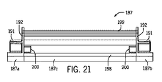
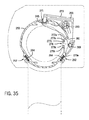
図12を参照すると、覆い110は、図28〜図47に関連して後述するピボット式に移動可能なロック機構と同様に、第1のシェード22が十分に延長された位置にあるときに外側ローラ50の回転を制約する、軸方向に移動可能なロック機構186を含む。軸方向に移動可能なロック機構186は、ハウジング187、ハウジング187にジャーナル式に取り付けられる回転可能なシャフト188、及びシャフト188とねじ式に係合され、シャフト188に沿って軸方向に移動可能なナット189を含むことができる。軸方向に移動可能なロック機構186は左端キャップ126bと併せて描画されるが、ロック機構186は右端キャップ126aと併せて用いられてもよい。   Referring to FIG. 12, the shroud 110 is external when the first shade 22 is in a fully extended position, similar to the pivotally movable locking mechanism described below in connection with FIGS. An axially movable locking mechanism 186 that restricts rotation of the roller 50 is included. The axially movable locking mechanism 186 is threadably engaged with the housing 187, a rotatable shaft 188 journaled to the housing 187, and the shaft 188, and is axially movable along the shaft 188. A nut 189 can be included. Although the lock mechanism 186 that can move in the axial direction is drawn together with the left end cap 126b, the lock mechanism 186 may be used together with the right end cap 126a.

図12、図16、及び図18を参照すると、ハウジング187は、左端キャップ126bから片持ちにされ、左端キャップ126bから外側ローラ150の外周に沿って右端キャップ126aの方に軸方向に延びてもよい。ハウジング187の一方の端187aは、ファスナ190で左端キャップ126bに取り外し可能に接続されてもよく、ハウジング187の反対の自由端187bは、外側ローラ150の横方向外方に位置付けられてもよい。ハウジング187は、外側ローラ150を中心とした又は外側ローラ150からの第1のシェード(図示せず)の巻きつけ又は繰り出しに干渉しないように十分な距離だけ外側ローラ150の辺縁から横方向に分離されてもよい。ハウジング187は、外側ローラ150の辺縁から横方向に一様な距離だけ分離されてもよい。   Referring to FIGS. 12, 16, and 18, the housing 187 is cantilevered from the left end cap 126b and extends axially from the left end cap 126b along the outer periphery of the outer roller 150 toward the right end cap 126a. Good. One end 187 a of the housing 187 may be removably connected to the left end cap 126 b at the fastener 190, and the opposite free end 187 b of the housing 187 may be positioned laterally outward of the outer roller 150. The housing 187 extends laterally from the edge of the outer roller 150 a sufficient distance so that it does not interfere with the winding or unwinding of a first shade (not shown) around or from the outer roller 150. It may be separated. The housing 187 may be separated from the edge of the outer roller 150 by a uniform distance in the lateral direction.

図16、図18、図21、及び図26を参照すると、ハウジング187の対向する端部187a、187bは、軸方向に延びるカラー191と、カラー191から外方に延びる当接フランジ192を含むことができる。カラー191は、内壁193に回転可能に支えられる回転可能なシャフト188のジャーナル部195を受け入れるシャフト孔194を画定する内壁193(図22及び図26参照)を含むことができる。カラー191の内壁193はまた、ハウジング187の内外へのシャフト188の軸方向の挿入又は除去中に回転可能なシャフト188(特に、回転可能なシャフト188上に形成される止め部197)の通過を可能にするキーホール196を画定することができる。各当接フランジ192は、ハウジング187をそれぞれの端キャップ126a、126b(図12、図14、図16、図18、及び図22参照)に接続するファスナ190を受け入れるように構成されたファスナ孔を画定することができる。ハウジング187の端部187a、187bは、ハウジング187と左端キャップ126b及び右端キャップ126aのいずれかとの相互接続を容易にするために互いの鏡像であってもよい。   With reference to FIGS. 16, 18, 21, and 26, the opposite ends 187 a, 187 b of the housing 187 include an axially extending collar 191 and an abutment flange 192 that extends outwardly from the collar 191. Can do. The collar 191 can include an inner wall 193 (see FIGS. 22 and 26) that defines a shaft hole 194 that receives a journal portion 195 of a rotatable shaft 188 that is rotatably supported by the inner wall 193. The inner wall 193 of the collar 191 also allows passage of a rotatable shaft 188 (particularly a stop 197 formed on the rotatable shaft 188) during axial insertion or removal of the shaft 188 into and out of the housing 187. An enabling keyhole 196 can be defined. Each abutment flange 192 has a fastener hole configured to receive a fastener 190 that connects the housing 187 to a respective end cap 126a, 126b (see FIGS. 12, 14, 16, 18, and 22). Can be defined. The ends 187a, 187b of the housing 187 may be mirror images of each other to facilitate interconnection of the housing 187 with either the left end cap 126b or the right end cap 126a.

図12、図16、図18、図21、及び図26を引き続き参照すると、ハウジング187は、端部187a、187bを相互接続する中間部187cを含むことができる。中間部187cは、横方向に離間された関係性で外側ローラ150の外周に沿って長手方向に延びることができる。ハウジング187の中間部187cは、それぞれハウジング187の対向する端部187a、187b間の距離にわたる、ベース198及びガイドレール199を含むことができる。ハウジング187のベース198は、シャフト188がハウジング187に対して回転している間にシャフト188の止め部が通れるようにするために端部187a、187bの近傍に止め部受入孔200を画定することができ、これにより、ハウジング187の横断プロファイルが減少する。ハウジング187のベース198は、端部187a、187b間に長手方向に延びる補強リブ201も含むことができ、これは、ハウジング187を補強し、ハウジング187の中間部187cの横方向の変位又は座屈を低減する。図27に示すように、補強リブ201は、長手方向に延びるリブ201の剛性をさらに増加させる、少なくとも1つの横方向に延びるバットレス202を含むことができる。   With continued reference to FIGS. 12, 16, 18, 21, and 26, the housing 187 can include an intermediate portion 187c that interconnects the ends 187a, 187b. The intermediate portion 187c can extend in the longitudinal direction along the outer periphery of the outer roller 150 in a laterally spaced relationship. The intermediate portion 187c of the housing 187 can include a base 198 and a guide rail 199 that span the distance between opposing ends 187a, 187b of the housing 187, respectively. The base 198 of the housing 187 defines a stop receiving hole 200 in the vicinity of the ends 187a, 187b to allow the stop of the shaft 188 to pass while the shaft 188 rotates relative to the housing 187. This reduces the transverse profile of the housing 187. The base 198 of the housing 187 can also include a reinforcing rib 201 that extends longitudinally between the ends 187a, 187b, which reinforces the housing 187 and lateral displacement or buckling of the intermediate portion 187c of the housing 187. Reduce. As shown in FIG. 27, the reinforcing rib 201 can include at least one laterally extending buttress 202 that further increases the rigidity of the longitudinally extending rib 201.

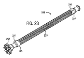
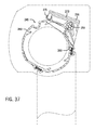
図12、図16〜図19、図23、及び図26を参照すると、軸方向に移動可能なロック機構186のシャフト188は、内側ローラ148の回転軸152からオフセットされるが、これと平行又は実質的に平行であってもよい。シャフト188は、外側ローラ150の外部に位置付けられ、離間された関係性で外側ローラ150の外周に沿って長手方向に延びてもよい。シャフト188は、ハウジング187のカラー191内に回転可能に受け入れられるジャーナル部195を含むことができる。シャフト188のジャーナル部195は、カラー191のベアリング面193とシャフト188のジャーナル部195との接触面積(したがって摩擦)を減らす凹型の周方向の領域を含むことができる。シャフト188は、シャフト188のジャーナル部195間及びハウジング187のカラー191間に延びるねじ部203を含むことができる。止め部197が、シャフト188のねじ部203の末端付近のシャフト188上に形成されてもよい。止め部197は、ハウジング187に対するシャフト188の回転中に止め部197が回転して孔200の内外に出入りするように、シャフト188から半径方向外方に延びてもよく、ハウジング187(図21参照)のベース198に形成された孔200と軸方向に位置合わせされてもよい。歯車204は、シャフト188の一方の端に回転不可能に取り付けられてもよく、歯車(したがってシャフト188)を端キャップ126bに対して横方向に配置するための中央キャビティを画定することができる。   Referring to FIGS. 12, 16-19, 23 and 26, the shaft 188 of the axially movable locking mechanism 186 is offset from the rotational axis 152 of the inner roller 148, but parallel or It may be substantially parallel. The shaft 188 may be positioned outside the outer roller 150 and may extend longitudinally along the outer periphery of the outer roller 150 in a spaced relationship. The shaft 188 can include a journal portion 195 that is rotatably received within the collar 191 of the housing 187. The journal portion 195 of the shaft 188 can include a concave circumferential region that reduces the contact area (and thus friction) between the bearing surface 193 of the collar 191 and the journal portion 195 of the shaft 188. The shaft 188 can include a threaded portion 203 that extends between the journal portions 195 of the shaft 188 and between the collars 191 of the housing 187. A stop 197 may be formed on the shaft 188 near the end of the threaded portion 203 of the shaft 188. The stop 197 may extend radially outward from the shaft 188 so that the stop 197 rotates into and out of the hole 200 during rotation of the shaft 188 relative to the housing 187, and the housing 187 (see FIG. 21). ) And the hole 200 formed in the base 198 may be aligned in the axial direction. The gear 204 may be non-rotatably attached to one end of the shaft 188 and may define a central cavity for positioning the gear (and thus the shaft 188) laterally relative to the end cap 126b.

図12、図16、図18、及び図24〜図27を参照すると、軸方向に移動可能なロック機構186のナット189は、少なくとも部分的にハウジング187内に位置付けられ、ハウジング187の中間部187c内でシャフト188に沿って軸方向に移動する。ナット189は、シャフト188が回転する際にナット189がシャフト188を中心として回転するのではなくシャフト188に沿って平行移動するようにハウジング187にキー式に取り付けられる。ナット189は、シャフト188の周りに部分的にのみ延びる、半ナット189と言ってもよい本体205を含む。代替的な設計では、ナット189は、シャフト188の全周に延びてもよい。   With reference to FIGS. 12, 16, 18, and 24-27, the nut 189 of the axially movable locking mechanism 186 is positioned at least partially within the housing 187 and the intermediate portion 187c of the housing 187 is provided. In the axial direction along the shaft 188. The nut 189 is keyed to the housing 187 so that when the shaft 188 rotates, the nut 189 does not rotate about the shaft 188 but translates along the shaft 188. The nut 189 includes a body 205, which may be referred to as a half-nut 189, that extends only partially around the shaft 188. In an alternative design, the nut 189 may extend around the entire circumference of the shaft 188.

図24及び図25を参照すると、ナット189は、本体205から内方に突き出てシャフト188のねじ部203の雄ねじとねじ式に係合する雌ねじ206を含む。ねじの係合を維持し、シャフト188を中心としたナット189の回転を制約するために、ナット189は、ナット189の本体から半径方向外方に突き出る2つの長手方向に延びるウィング207を含むことができる。ウィング207は、ナット189とハウジング187との接触面積(したがって摩擦)を減らしながら、ハウジング187のベース198(図27参照)の対立する面にスライド可能に接触し、ナット189をハウジング187の中間部187cに沿って軸方向に案内する、軸方向に延びるフィン208を含むことができる。   Referring to FIGS. 24 and 25, the nut 189 includes an internal thread 206 that protrudes inwardly from the main body 205 and engages with an external thread of the threaded portion 203 of the shaft 188. In order to maintain screw engagement and constrain the rotation of nut 189 about shaft 188, nut 189 includes two longitudinally extending wings 207 that project radially outward from the body of nut 189. Can do. The wing 207 slidably contacts the opposing surface of the base 198 of the housing 187 (see FIG. 27) while reducing the contact area (and hence friction) between the nut 189 and the housing 187, and the nut 189 is placed in the middle of the housing 187. An axially extending fin 208 may be included that guides axially along 187c.

ウィング207のうちの1つは、ガイドレール199を少なくとも部分的に受け入れる長手方向に延びるスロット208を画定することができる。図27に示すように、スロット208を画定するウィング207の一部は、ガイドレール199の異なる側部にスライド可能に当接することができる。したがって、ナット189のウィング207は、ナット189がシャフト188を中心として回転するのを実質的に防ぐことができ、これにより、ハウジング187に対するシャフト188の回転中のナット189のシャフト188に沿った平行移動を容易にする。ウィング207を横方向に補強するために、ナット189は、雌ねじ206の外方に位置付けられ、ウィング207間に延びる、横方向に延びるリブ209を含むことができる。代替的な設計では、ナット189及びハウジング187は、シャフト188がハウジング187に対して回転するとナット189がシャフト188に沿って軸方向に移動するように、種々の他の対応するキー構造体を含むことができる。   One of the wings 207 can define a longitudinally extending slot 208 that at least partially receives the guide rail 199. As shown in FIG. 27, a portion of the wing 207 defining the slot 208 can slidably abut against different sides of the guide rail 199. Thus, the wings 207 of the nut 189 can substantially prevent the nut 189 from rotating about the shaft 188, thereby providing parallelism along the shaft 188 of the nut 189 during rotation of the shaft 188 relative to the housing 187. Make it easy to move. To laterally reinforce the wing 207, the nut 189 can include laterally extending ribs 209 that are positioned outwardly of the internal thread 206 and extend between the wings 207. In alternative designs, nut 189 and housing 187 include a variety of other corresponding key structures such that nut 189 moves axially along shaft 188 as shaft 188 rotates relative to housing 187. be able to.

説明したように、ハウジング187に対するシャフト188の回転が、ナット189をシャフト188に沿って軸方向に概して動かす又は平行移動する。ナット189の軸方向の範囲を制限するために、シャフト188は、シャフト188の辺縁から外方に延びる止め部197を含むことができる。ナット189と接触すると、止め部197は、シャフト188に対するナット189の平行移動を概して制約又は制限し、これにより、ハウジング187に対するシャフト188のさらなる回転を制約又は制限する。ナット189とそれぞれの止め部197との間の確固とした係合を保証するために、ナット189は、ナット189が第1のシェード22のフル延長に対応する所望の停止位置に到達するとシャフト188の止め部と相互作用する、長手方向に延びる当接壁211を含むことができる。図24に示すように、当接壁211は、ナット189の雌ねじ206の末端に形成されてもよい。   As described, rotation of the shaft 188 relative to the housing 187 generally moves or translates the nut 189 axially along the shaft 188. To limit the axial extent of the nut 189, the shaft 188 can include a stop 197 that extends outward from the edge of the shaft 188. In contact with the nut 189, the stop 197 generally restricts or restricts the translation of the nut 189 relative to the shaft 188, thereby restricting or restricting further rotation of the shaft 188 relative to the housing 187. In order to ensure a firm engagement between the nut 189 and each stop 197, the nut 189 is configured such that when the nut 189 reaches a desired stop position corresponding to the full extension of the first shade 22, the shaft 188. A longitudinally extending abutment wall 211 may be included that interacts with the stop. As shown in FIG. 24, the contact wall 211 may be formed at the end of the female thread 206 of the nut 189.

加えて又は代替的に、ナット189の本体205(軸方向に延びるスリーブと似ている場合がある)は、シャフト188に沿ったナット189の平行移動を止めるためにハウジング187の当接フランジ192と当接してもよい。ナット189の本体205は、シャフト188と本体205との間に画定される環状空間内のシャフト止め部197の通過を可能にするのに十分な距離だけシャフト188の外周から半径方向に離間されてもよい。シャフト188及びナット189は、ロック機構186と右端キャップ126a及び左端キャップ126bとの相互操作性を容易にするためにそれぞれ2つの止め部197及び当接壁211を含んでもよく、これにより、左手側組立体及び右手側組立体に適応することができる堅牢な設計を提供する。   In addition or alternatively, the body 205 of the nut 189 (which may be similar to an axially extending sleeve) is in contact with the abutting flange 192 of the housing 187 to stop translation of the nut 189 along the shaft 188. You may contact. The body 205 of the nut 189 is radially spaced from the outer periphery of the shaft 188 by a distance sufficient to allow passage of the shaft stop 197 in the annular space defined between the shaft 188 and the body 205. Also good. The shaft 188 and the nut 189 may include two stoppers 197 and an abutment wall 211, respectively, to facilitate interoperability between the locking mechanism 186 and the right end cap 126a and the left end cap 126b. It provides a robust design that can accommodate the assembly and right hand side assembly.

図15〜図17を参照すると、軸方向に移動可能なロック機構186は、内側ローラ148及び外側ローラ150の外部に位置付けられる歯車機構又はトレイン213を含むことができる。歯車機構又はトレイン213は、外側ローラ150に回転不可能に結合される第1の歯車215、シャフト188に回転不可能に結合される第2の歯車204、並びに、第1の歯車215及び第2の歯車204と互いにかみ合わされるアイドラー歯車217を含むことができる。アイドラー歯車217は、マウンティングプレート219(図17参照)から関連する端キャップ126の方に軸方向に突き出るロケータピン221を含むマウンティングプレート219上に回転可能に支持されてもよい。ロケータピン221は、端キャップ126に対するマウンティングプレート219の回転を制約するために端キャップ126内に受け入れ可能であってもよい。   Referring to FIGS. 15-17, the axially movable locking mechanism 186 can include a gear mechanism or train 213 positioned outside the inner roller 148 and the outer roller 150. The gear mechanism or train 213 includes a first gear 215 that is non-rotatably coupled to the outer roller 150, a second gear 204 that is non-rotatably coupled to the shaft 188, and the first gear 215 and the second gear 215. And an idler gear 217 that meshes with each other. The idler gear 217 may be rotatably supported on a mounting plate 219 that includes a locator pin 221 that protrudes axially from the mounting plate 219 (see FIG. 17) toward the associated end cap 126. The locator pin 221 may be receivable within the end cap 126 to constrain the rotation of the mounting plate 219 relative to the end cap 126.

歯車機構213は、シェード部材のサイズ、重量、又は他の特徴に応じて変更されてもよい。一例では、歯車機構213は、第1の歯車215と第2の歯車204との間で3対1の歯車比を提供する。すなわち、外側ローラ150の1回転につきシャフト188が3回転する。一例では、シャフト188の雄ねじは、1インチにつき16個(又は1インチの1/16のピッチ)のねじ山を有する。一般に、シャフト188のねじ部203の長さは、シャフト188が多くの異なるシェード長さに適応できるようにナット189の動作可能な範囲に対してオーバーサイズにされてもよい。したがって、或る例では、ナット189は、動作中に回転可能なシャフト188上の止め部197のうちの1つとだけ相互作用し、他の止め部は、ロック機構186が右端キャップ126a又は左端キャップ126bのうちのいずれかと共に用いられ得るように提供される。   The gear mechanism 213 may be changed depending on the size, weight, or other characteristics of the shade member. In one example, the gear mechanism 213 provides a 3 to 1 gear ratio between the first gear 215 and the second gear 204. That is, the shaft 188 rotates three times for each rotation of the outer roller 150. In one example, the male thread of shaft 188 has 16 threads per inch (or 1/16 pitch of 1 inch). In general, the length of threaded portion 203 of shaft 188 may be oversized relative to the operable range of nut 189 so that shaft 188 can accommodate many different shade lengths. Thus, in one example, the nut 189 interacts with only one of the stops 197 on the rotatable shaft 188 during operation, while the other stops are locked by the locking mechanism 186 by the right end cap 126a or the left end cap. 126b is provided for use with any of 126b.

図15を参照すると、歯車機構213が左端キャップ126bに関連して示される。外側歯車204、215、217は、左端キャップ126bから軸方向に突き出るスタブシャフトによって回転可能に支持される。アイドラー歯車217は、第1の歯車215の前方に位置付けられ、第2の歯車204は、アイドラー歯車217の前方に位置付けられ、この場合、すべての3つの歯車215、204、217は端キャップに隣接して同一平面内に配置される。アイドラー歯車217は、第1の歯車215の上方に位置付けられ、第2の歯車204は、アイドラー歯車217の上方に位置付けられる。第1の歯車215及びアイドラー歯車217は、端キャップ126bから軸方向に突き出るリム223内に受け入れられてもよい。   Referring to FIG. 15, the gear mechanism 213 is shown in relation to the left end cap 126b. The outer gears 204, 215, and 217 are rotatably supported by a stub shaft that protrudes in the axial direction from the left end cap 126b. The idler gear 217 is positioned in front of the first gear 215 and the second gear 204 is positioned in front of the idler gear 217, where all three gears 215, 204, 217 are adjacent to the end cap. Are arranged in the same plane. The idler gear 217 is positioned above the first gear 215, and the second gear 204 is positioned above the idler gear 217. The first gear 215 and idler gear 217 may be received in a rim 223 that protrudes axially from the end cap 126b.

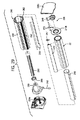
図13を参照すると、ヘッドレール構成要素(図6〜図11に関連して図示及び説明したものと概して同じ右側構成要素を除く)の部分分解図が提供される。構成要素は、左端キャップ126b、左端キャップ126bに取り付けられる回転可能でない制限ねじ166、制限ねじ166のベアリング面上に設置され、これに対して回転する左ブッシング170b、制限ねじ166(制限ナット168を含む)の一部を内部に受け入れ、左ブッシング170b及び右ブッシング170aのボス167上に設置される内側ローラ148、内側ローラ148を内部に受け入れる外側ローラ150、及び左端キャップ126bに取り付けられる軸方向に移動可能なロック機構186を含む。   Referring to FIG. 13, a partial exploded view of a headrail component (except for generally the same right side components as shown and described in connection with FIGS. 6-11) is provided. The components are a left end cap 126b, a non-rotatable limit screw 166 attached to the left end cap 126b, a left bushing 170b that rotates on the bearing surface of the limit screw 166, and a limit screw 166 (with a limit nut 168). The inner roller 148 installed on the bosses 167 of the left bushing 170b and the right bushing 170a, the outer roller 150 receiving the inner roller 148 therein, and the axial direction attached to the left end cap 126b. A movable locking mechanism 186 is included.

図13、図14、図19、及び図20を参照すると、外側ローラ150は、スプリットシェル設計を含むことができる。特に、外側ローラ150は、第1のシェル154及び第2のシェル156を含むことができる。第1のシェル154及び第2のシェル156を一緒に固定し、互いに対する所望の空間的関係を維持するために、外側ローラ150の第1のシェル154及び第2のシェル156は、それぞれ、左ブッシング170b及び右ブッシング170aの軸方向の突起172a、172bをすっぽり受け入れることができる(図14、図18、及び図19参照)。軸方向の突起172a、172bは、外側ローラ150とブッシング170a、170bが外側ローラ150の回転軸152を中心として一緒に回転するように、外側ローラ150をブッシング170a、170bに結合することができる。第1の歯車215は、軸方向の突起172a、172bに対する左ブッシング170bの対向する面に回転不可能に固定されてもよく、これにより、確実に第1の歯車215が外側ローラ150と一緒に回転する。第1のシェル154と第2のシェル156を一緒にさらに固定するために、シェル154、156は、少なくとも1つの保持クリップ225によって一緒にクランプされてもよい(図12〜図13は、2つの保持クリップを描画するが、シェルを一緒に確実に締結するために要望に応じてより多くの又は少ないクリップが用いられてもよい)。図20に示すように、保持クリップ225は、第1のシェル154及び第2のシェル156の嵌合領域227の周りに弾性的にスナップされてもよい。   Referring to FIGS. 13, 14, 19, and 20, the outer roller 150 can include a split shell design. In particular, the outer roller 150 can include a first shell 154 and a second shell 156. In order to secure the first shell 154 and the second shell 156 together and maintain the desired spatial relationship with each other, the first shell 154 and the second shell 156 of the outer roller 150 are respectively left The axial protrusions 172a and 172b of the bushing 170b and the right bushing 170a can be completely received (see FIGS. 14, 18 and 19). The axial protrusions 172a, 172b can couple the outer roller 150 to the bushings 170a, 170b such that the outer roller 150 and the bushings 170a, 170b rotate together about the axis of rotation 152 of the outer roller 150. The first gear 215 may be non-rotatably secured to the opposing surface of the left bushing 170b relative to the axial protrusions 172a, 172b, thereby ensuring that the first gear 215 together with the outer roller 150 Rotate. To further secure the first shell 154 and the second shell 156 together, the shells 154, 156 may be clamped together by at least one retaining clip 225 (FIGS. Draws retaining clips, but more or fewer clips may be used as desired to ensure the shells are fastened together). As shown in FIG. 20, the retaining clip 225 may be resiliently snapped around the mating region 227 of the first shell 154 and the second shell 156.

図20を参照すると、第1のシェル154の端部158と第2のシェル156の端部160は、互いに重なり、長手方向に延びるリップ233、235によって少なくとも部分的に画定される対応する長手方向に延びる受入チャネル229、231の中に延びることができる。第1のシェル158のリップ233は、第2のシェル160の末端の長手方向に延びる縁237の内部に位置付けられてもよく、一方、第2のシェル160のリップ235は、第1のシェル158の末端の長手方向に延びる縁239の外部に位置付けられてもよい(しかし、この配置は反転されてもよい)。第1のシェル154と第2のシェル156を一緒にクランプするために、第1のシェル154及び第2のシェル156の嵌合領域にそれぞれ形成される外部戻り止め241、243の周りに保持クリップ225を弾性的にスナップしてもよい。   Referring to FIG. 20, the end 158 of the first shell 154 and the end 160 of the second shell 156 overlap each other and are at least partially defined by longitudinally extending lips 233, 235. Can extend into receiving channels 229, 231 that extend into the channel. The lip 233 of the first shell 158 may be positioned within the longitudinally extending edge 237 of the distal end of the second shell 160, while the lip 235 of the second shell 160 is positioned within the first shell 158. May be positioned outside the longitudinally extending edge 239 of the distal end (but this arrangement may be reversed). Retaining clips around external detents 241 and 243 formed in mating regions of the first shell 154 and the second shell 156, respectively, for clamping the first shell 154 and the second shell 156 together 225 may be snapped elastically.

図14及び図19を参照すると、外側ローラ150のスプリットシェル設計は、第2のシェード24の延長及び後退中に第2のシェード24を通すことができる長手方向に延びるスロット176を画定する。第1のシェル154の縁部158と第2のシェル156の縁部160が互いに嵌合されるときに、第1のシェル154及び第2のシェル156の反対の又は第2の長手方向に延びる末端縁部178、180は、互いから周方向に離間され、長手方向に延びるスロット176を画定する。第1のシェル154及び第2のシェル156の対立する第2の末端縁部158、160は、第2のシェード24のボトムレール20の通過を防ぎながら第2のシェード24の通過を可能にするのに十分な距離だけ互いから離間されてもよい。外側ローラ150の機能は、図6〜図11に関連して説明した機能と概して同じであり、したがって、簡潔さのためにここでは繰り返さない。   14 and 19, the split shell design of the outer roller 150 defines a longitudinally extending slot 176 through which the second shade 24 can be passed during extension and retraction of the second shade 24. When the edge 158 of the first shell 154 and the edge 160 of the second shell 156 are mated together, they extend in the opposite or second longitudinal direction of the first shell 154 and the second shell 156. The distal edges 178, 180 are circumferentially spaced from one another and define a longitudinally extending slot 176. Opposing second end edges 158, 160 of the first shell 154 and the second shell 156 allow passage of the second shade 24 while preventing passage of the bottom rail 20 of the second shade 24. May be separated from each other by a sufficient distance. The function of the outer roller 150 is generally the same as that described in connection with FIGS. 6-11 and is therefore not repeated here for the sake of brevity.

覆いの動作中に、外側ローラ150が第1のシェード22を建築物の開口部にわたって延長する際に、第1の歯車215がアイドラー歯車217を駆動し、これにより第2の歯車204を駆動して、ナット189を軸方向にシャフト188に沿って下端位置の方に旋回により移動させる。ナット189が下端位置(シャフト188上の止め部197によって画定される場合がある)に到達すると、ナット189は、第1のシェード22の延長方向のシャフト188のさらなる回転を制約し、これにより、外側ローラ150の延長方向のさらなる回転を抑制する。外側ローラ150が延長方向のさらなる回転を制約され、かつ、第1のシェード22が外側ローラ150の辺縁から繰り出された状態で、第2のシェード24が、内側ローラ148から繰り出され、外側ローラ150のスロット176を通り、建築物の開口部にわたって延長されてもよい。第2のシェード24の延長中に内側ローラ148が回転する際に、内部制限ナット168が内側ローラ148と一緒に回転し、軸方向に制限ねじ166に沿って回転可能でない制限ねじ166上に形成された下側端止め部の方に移動する。内部制限ナット166は、一般に、第2のシェード24が建築物の開口部にわたって十分に延長されると下側端止め部に接触してデュアルローラユニット146の下側止め部を画定する。   During the covering operation, the first gear 215 drives the idler gear 217, thereby driving the second gear 204, as the outer roller 150 extends the first shade 22 across the building opening. Then, the nut 189 is moved by turning in the axial direction along the shaft 188 toward the lower end position. When the nut 189 reaches the lower end position (which may be defined by a stop 197 on the shaft 188), the nut 189 constrains further rotation of the shaft 188 in the direction of extension of the first shade 22, thereby Further rotation of the outer roller 150 in the extending direction is suppressed. With the outer roller 150 restricted from further rotation in the extension direction and the first shade 22 being fed out from the edge of the outer roller 150, the second shade 24 is fed out from the inner roller 148, and the outer roller It may extend through the 150 slots 176 and over the opening of the building. As the inner roller 148 rotates during the extension of the second shade 24, the inner limiting nut 168 rotates with the inner roller 148 and forms on the limiting screw 166 that is not axially rotatable along the limiting screw 166. Move toward the lower end stop. The internal limit nut 166 generally contacts the lower end stop and defines the lower stop of the dual roller unit 146 when the second shade 24 is fully extended across the building opening.

十分に延長された位置からの覆いの後退中に、内側ローラ148が、外側ローラ150のシェル154、156の対向する長手方向に延びる縁部178、180間に画定されたスロット176を通して第2のシェード24を引き、第2のシェード24を第2のシェード24のボトムレール20が外側ローラ150の外周に着座するまで内側ローラ148の周縁に巻きつける。第2のシェード24の後退中に、第1のシェード22のボトムレール18の重量がブッシング170a、170bを静止した状態に維持し、したがって、内側ローラ148は、ブッシング170a、170b及び外側ローラ150に対して回転する。   During retraction of the cover from the fully extended position, the inner roller 148 passes through a slot 176 defined between opposing longitudinally extending edges 178, 180 of the shells 154, 156 of the outer roller 150. The shade 24 is pulled, and the second shade 24 is wound around the periphery of the inner roller 148 until the bottom rail 20 of the second shade 24 is seated on the outer periphery of the outer roller 150. During the retraction of the second shade 24, the weight of the bottom rail 18 of the first shade 22 keeps the bushings 170a, 170b stationary, so that the inner roller 148 is in contact with the bushings 170a, 170b and the outer roller 150. Rotate against.

着座されると、第2のシェード24のボトムレール20が内側ローラ148から外側ローラ150に回転トルクを伝達し、これにより、外側ローラ150を後退方向に回転させ、第1のシェード22を外側ローラ150の周縁に巻きつける。内側ローラ148及び外側ローラ150は、第1のシェード22のボトムレール18が端キャップ126の一方又は両方と関連付けられてもよい上側制限止め部に接触するまで後退方向に回転し続け、その時点で覆いは十分に後退された位置に後退させられる。内側ローラ148の後退方向の回転中に、内部制限ナット168が内側ローラ148内で回転可能でない制限ねじ166に沿って第2のシェード24の下側止め部から離れる方に旋回により移動する。外側ローラ150の後退方向の回転中に、外部ナット189が回転可能なシャフト188に沿って第1のシェード22の下側止め部から離れる方に旋回により移動する。   When seated, the bottom rail 20 of the second shade 24 transmits rotational torque from the inner roller 148 to the outer roller 150, thereby rotating the outer roller 150 in the backward direction and causing the first shade 22 to move to the outer roller. Wrap around the periphery of 150. Inner roller 148 and outer roller 150 continue to rotate in the retracted direction until bottom rail 18 of first shade 22 contacts an upper limit stop that may be associated with one or both of end caps 126, at which point The cover is retracted to a fully retracted position. During rotation of the inner roller 148 in the retracted direction, the inner limiting nut 168 moves by pivoting away from the lower stop of the second shade 24 along a limiting screw 166 that is not rotatable within the inner roller 148. During rotation of the outer roller 150 in the retracting direction, the outer nut 189 moves along a rotatable shaft 188 away from the lower stopper of the first shade 22 by turning.

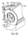
図28〜図47を参照すると、ピボット運動可能なロック機構を含む建築物の開口部のための覆いが提供される。ピボット運動可能なロック機構と多部品の外側ローラを除いて、図28〜図47に描画される覆いは、図6〜図27に描画される覆いと概して同じ特徴及び動作を有する。したがって、図6〜図27に描画される覆いの特徴及び動作の上記の説明は、以下の解説で述べられることを除いて、図28〜図47に描画される覆いに概して適用可能と考えられるべきである。図28〜図47で用いられる参照番号は、参照番号が100だけ増加されていることを除いて、同様の部分及び構成要素を反映するべく図12〜図27で用いられる参照番号と概して対応する。   Referring to FIGS. 28-47, a cover for an opening in a building including a pivotable locking mechanism is provided. Except for a pivotable locking mechanism and a multi-part outer roller, the cover depicted in FIGS. 28-47 has generally the same features and operations as the cover depicted in FIGS. Accordingly, the above description of the features and operation of the cover depicted in FIGS. 6-27 is generally considered applicable to the cover depicted in FIGS. 28-47, except as noted in the following discussion. Should. The reference numbers used in FIGS. 28-47 generally correspond to the reference numbers used in FIGS. 12-27 to reflect similar parts and components, except that the reference numbers have been increased by 100. .

図28〜図34を参照すると、内側ローラ248は、概して円筒形の形状であり、第2のシェード24の上縁をこれに固定するための保持部材を形成する。上述のように、内側ローラ248は、デュアルローラユニットを画定するべく外側ローラ250の内部に位置付けられ、この例では、両方のローラ248、250は同じ回転軸252を中心として同延である。第2のシェード24の上縁は内側ローラ248に取り付けられ、第2のシェード24の下縁は、第2のボトムレール220に形成されたスロットに受け入れられ、第2のシェード24の下縁に形成されたヘムに入れられるインサート282によってスロットの中に保持される。ボトムレール220を第2のシェード24に取り付けるために他の取付構造体が用いられてもよい。   28-34, the inner roller 248 is generally cylindrical in shape and forms a retaining member for securing the upper edge of the second shade 24 thereto. As described above, the inner roller 248 is positioned inside the outer roller 250 to define a dual roller unit, and in this example, both rollers 248, 250 are co-extensive about the same axis of rotation 252. The upper edge of the second shade 24 is attached to the inner roller 248, and the lower edge of the second shade 24 is received in a slot formed in the second bottom rail 220, and the lower edge of the second shade 24 is Retained in the slot by an insert 282 that is placed into the formed hem. Other attachment structures may be used to attach the bottom rail 220 to the second shade 24.

図28〜図34を続けると、第2のボトムレール220は、比較的高い質量を有し、かつ、前述のように第2のシェード24の下縁を受け入れ、保持するためにその長さに沿って延びるスロットを画定する、細長い部材である。第2のボトムレール220は概して三角形の断面を有し、その一部は、第2のシェード24が後退位置にあるときに外側ローラ250上に形成された座部281の形状に適合するべくその形状に概して合致する。アクチュエータリム247が、第2のレール220の一方の端に画定され、より詳細に後述するように外側ローラ250からロック機構286を係合解除するべくロック機構286と係合する。   Continuing with FIGS. 28-34, the second bottom rail 220 has a relatively high mass and is at its length to receive and hold the lower edge of the second shade 24 as previously described. An elongate member defining a slot extending along. The second bottom rail 220 has a generally triangular cross section, a portion of which is adapted to conform to the shape of the seat 281 formed on the outer roller 250 when the second shade 24 is in the retracted position. Generally matches the shape. An actuator rim 247 is defined at one end of the second rail 220 and engages the locking mechanism 286 to disengage the locking mechanism 286 from the outer roller 250 as described in more detail below.

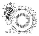
外側ローラ250は、この例では概して円筒形であり、その周壁にいくつかの特徴を画定する。外側ローラ250は、それを中心として回転する長手方向の中心軸252を画定し、それを中心として内側ローラ248も同延に位置付けられる。第1のシェード22の上縁を受け入れ、固定するために一対のチャネル262が形成され、この場合、インサート264が、それぞれ、各上縁に形成されたヘムに入れられ、インサート264は、それぞれのチャネル262内に上縁を保持するように作用する。アンカー溝245が、後述するようにローラロックベアリングを受け入れるために外側ローラ250の長さに沿って形成される。スロット276が、外側ローラ250の長さに沿って形成され、チューブとして形成され得る外側ローラ250の内部と連通する。凹型の座部281がスロット276の両側に形成される。第2のシェード24がスロット276を通して延長及び後退され、十分に後退された位置にあるときに、第2のボトムレール220が、座部281に受け入れられ、後述するように多くの目的のうちの少なくとも1つのためにその中で入れ子になる。スロット276は、第1のシェード22がその延長位置にあり、かつ、ベーンが開いた構成にあるときに、2つのチャネル262の最後部の上に及びこれに隣接して存在するように外側ローラ250上に位置付けられる。   The outer roller 250 is generally cylindrical in this example and defines several features on its peripheral wall. The outer roller 250 defines a longitudinal central axis 252 that rotates about it, about which the inner roller 248 is also located. A pair of channels 262 are formed to receive and secure the upper edge of the first shade 22, where inserts 264 are each placed in the hem formed on each upper edge, and the inserts 264 are respectively It acts to retain the upper edge within the channel 262. Anchor grooves 245 are formed along the length of outer roller 250 to receive roller lock bearings as will be described below. A slot 276 is formed along the length of the outer roller 250 and communicates with the interior of the outer roller 250, which can be formed as a tube. A concave seat 281 is formed on both sides of the slot 276. When the second shade 24 is extended and retracted through the slot 276 and is in the fully retracted position, the second bottom rail 220 is received in the seat 281 and is of many purposes as will be described below. Nested in it for at least one. The slot 276 is an outer roller so that the first shade 22 is in its extended position and is present above and adjacent to the end of the two channels 262 when the vane is in the open configuration. Positioned on 250.

図28、図29、図46、及び図47を参照すると、デュアルローラユニットは、右端キャップ226aと左端キャップ226bとの間に回転可能に支持され、動作機構240が、内側ローラチューブ248を回転させるために内側ローラチューブ248と動作可能に関連付けられる。動作機構240は、右端キャップ226aに取り付けられ、一例では、上記のように動作要素242によって作動される。動作機構240は、一例では、窓を覆う用途でしばしば用いられる遊星歯車駆動装置を含むことができる。動作機構240は、動作機構240によって回転される内部フィッティング264を含むことができる。フィッティング264は、内側ローラ248内に受け入れられ、内側ローラ248の内壁とぴったり係合するサイズにされる。内側ローラ248は、動作機構240によって内部フィッティング264が駆動される際に内部フィッティング264によって回転駆動される。外側ローラ250の開放右端は、右端ローラキャップ270aを受け入れ、これは、動作機構240のハウジング上に形成される軸方向のベアリング面を回転可能に受ける軸方向に延びるカラーを有する中央孔を含む。ベアリング面は、外側ローラ250が回転するときに右端ローラキャップ270aが回転する際にこれを支持する。内側ローラ248は、カラー上に回転可能に受け入れられる。カラーは、動作機構240によって回転駆動される際の内側チューブ248の右端を回転可能に支持する。   Referring to FIGS. 28, 29, 46, and 47, the dual roller unit is rotatably supported between the right end cap 226a and the left end cap 226b, and the operating mechanism 240 rotates the inner roller tube 248. Is operatively associated with the inner roller tube 248. The operating mechanism 240 is attached to the right end cap 226a and, in one example, is actuated by the operating element 242 as described above. The operating mechanism 240 can include, in one example, a planetary gear drive that is often used in applications that cover windows. The operating mechanism 240 can include an internal fitting 264 that is rotated by the operating mechanism 240. The fitting 264 is received within the inner roller 248 and is sized to closely engage the inner wall of the inner roller 248. The inner roller 248 is rotationally driven by the internal fitting 264 when the internal fitting 264 is driven by the operating mechanism 240. The open right end of the outer roller 250 receives a right end roller cap 270a that includes a central bore having an axially extending collar that rotatably receives an axial bearing surface formed on the housing of the operating mechanism 240. The bearing surface supports the right end roller cap 270a when the outer roller 250 rotates. Inner roller 248 is rotatably received on the collar. The collar rotatably supports the right end of the inner tube 248 when rotated by the operating mechanism 240.

図46に示すように、内側ローラ248の右端248aと外側ローラ250の右端250aはそれぞれ互いに位置合わせされてもよく、第2のシェード24の右側縁24aは、ローラ248、250の右端248a、250aと位置合わせされてもよい。図47に示すように、内側ローラ248の左端248bと外側ローラ250の左端250bはそれぞれ互いと位置合わせされてもよく、第2のシェード24の左側縁24bは、ローラ248、250の左端248b、250bと位置合わせされてもよい。第1のシェード22は、外側ローラ250に巻きつけられてもよく、第1のシェード22の縁は、ローラ248、250の端及び第2のシェード24の縁と位置合わせされてもよい。ローラ248、250の端及びシェード22、24の縁の位置合わせは、シェードの縁と建築物の開口部の対応する側部との間の光の隙間を減らす又はなくすことができる。   As shown in FIG. 46, the right end 248a of the inner roller 248 and the right end 250a of the outer roller 250 may be aligned with each other, and the right edge 24a of the second shade 24 is aligned with the right ends 248a, 250a of the rollers 248, 250. And may be aligned. 47, the left end 248b of the inner roller 248 and the left end 250b of the outer roller 250 may each be aligned with each other, and the left edge 24b of the second shade 24 may be aligned with the left ends 248b of the rollers 248, 250, 250b may be aligned. The first shade 22 may be wrapped around the outer roller 250, and the edge of the first shade 22 may be aligned with the ends of the rollers 248, 250 and the edge of the second shade 24. The alignment of the ends of the rollers 248, 250 and the edges of the shades 22, 24 can reduce or eliminate light gaps between the edges of the shade and the corresponding sides of the building opening.

外側ローラ250は、第2のシェード24が内側ローラ248上に十分に後退され、第2の端レール220が外側チューブ250の座部281に受け入れられるときに内側ローラ248によって回転駆動される。この状態で、内側ローラ248が回転する際に、第2のシェード24が第2の端レール220に張力をかけ、これにより、第2の端レール220と座部281との間の境界面で外側ローラ250に力がかかる。したがって、外側ローラ250は、内側ローラ248と連動して回転させられる。外側ローラ250は、第2のシェード24が内側ローラ248を中心として十分に後退されない限り、内側ローラ248と共に回転しない。上述のように、動作機構240は、ユーザによる要望に応じて第1のシェード22及び第2のシェード24を延長する又は後退させるべく動作要素242によって作動されてもよい。動作要素242の作動時に内側ローラチューブ248を回転させるための多くのタイプの機構が容認可能である。   The outer roller 250 is rotationally driven by the inner roller 248 when the second shade 24 is fully retracted onto the inner roller 248 and the second end rail 220 is received in the seat 281 of the outer tube 250. In this state, when the inner roller 248 rotates, the second shade 24 applies tension to the second end rail 220, and thereby, at the interface between the second end rail 220 and the seat portion 281. A force is applied to the outer roller 250. Accordingly, the outer roller 250 is rotated in conjunction with the inner roller 248. The outer roller 250 does not rotate with the inner roller 248 unless the second shade 24 is fully retracted about the inner roller 248. As described above, the operating mechanism 240 may be actuated by the operating element 242 to extend or retract the first shade 22 and the second shade 24 as desired by the user. Many types of mechanisms for rotating the inner roller tube 248 upon actuation of the motion element 242 are acceptable.

図28及び図29を続けると、制限ねじ266が内側ローラ248の内部に位置付けられ、ねじによって左端キャップ226bに動作可能に固定される。制限ねじ266は回転しない。制限ナット268が、制限ねじ266とねじ式に係合され、内側ローラ248の内部に回転によりキー式に取り付けられ、キー構造は、内側ローラ248の長さに沿った制限ナット268の移動を可能にする。内側ローラ248が回転する際に、制限ナット268が、ねじ込まれた制限シャフト266に沿って移動し、第2のシェード24の最下延長位置(図5参照)を画定する制限止め部と係合する。第1のシェード22の後退位置は、この例では外側ローラ250の周りに完全に巻きつけられている第1のシェード22によって画定される。或る例では、第1のボトムレール18が、この位置を画定するべくヘッドレール14の一部と係合する。代替的に又は加えて、この例では制限ねじ266上に上側制限止め部が用いられていないが、望まれる場合には制限ねじ266上に採用されてもよい。左端キャップ226bは、図28、図29、及び図47で最もよく分かるように、内側ローラ248及び外側ローラ250を回転可能に支持する。   Continuing with FIGS. 28 and 29, the limiting screw 266 is positioned inside the inner roller 248 and is operably secured to the left end cap 226b by the screw. The limiting screw 266 does not rotate. A limit nut 268 is threadably engaged with the limit screw 266 and is keyed by rotation within the inner roller 248, and the key structure allows movement of the limit nut 268 along the length of the inner roller 248 To. As the inner roller 248 rotates, the limit nut 268 moves along the threaded limit shaft 266 and engages a limit stop that defines the lowest extended position of the second shade 24 (see FIG. 5). To do. The retracted position of the first shade 22 is defined by the first shade 22 that is fully wrapped around the outer roller 250 in this example. In one example, the first bottom rail 18 engages a portion of the head rail 14 to define this position. Alternatively or additionally, the upper limit stop is not used on the limit screw 266 in this example, but may be employed on the limit screw 266 if desired. The left end cap 226b rotatably supports the inner roller 248 and the outer roller 250, as best seen in FIGS. 28, 29, and 47.

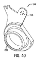
図28、図29、及び図40を参照すると、ピボットブラケット249が、左端キャップ226bの内面に取り付けられ、中央に位置付けられる環状ボス251と、ローラロック255がピボット式に設置される軸として役立つ右端キャップ226aの方に延びる支柱253とを画定する。ピボットブラケット249上の環状ボス251は、これ自体は外側ローラ250の開放左端に受け入れられる、左外側ローラキャップ270bの中央孔に回転可能に受け入れられる。カラーが、キャップ270bの中央孔の周りから軸方向に延び、外側ローラ250と左端ブラケットとの相対回転のためのベアリング面として役立つ。内側ローラ248の開放左端は、カラーの外面上に回転可能に受け入れられ、これはカラーに対するローラ248の回転のためのベアリング面として作用し、その回転は動作機構240を通じた選択的な制御の下にある。   Referring to FIGS. 28, 29 and 40, a pivot bracket 249 is attached to the inner surface of the left end cap 226b and has a centrally positioned annular boss 251 and a right end serving as a pivotally mounted shaft for the roller lock 255. A post 253 extending toward the cap 226a is defined. The annular boss 251 on the pivot bracket 249 is rotatably received in the central hole of the left outer roller cap 270b, which is itself received at the open left end of the outer roller 250. A collar extends axially around the central hole of the cap 270b and serves as a bearing surface for relative rotation of the outer roller 250 and the left end bracket. The open left end of the inner roller 248 is rotatably received on the outer surface of the collar, which acts as a bearing surface for the rotation of the roller 248 relative to the collar, which rotation is under selective control through the operating mechanism 240. It is in.

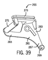
ローラロック255が、図28、図29、図38、及び図39に示すように、ピボットブラケット249(図40及び図41参照)上の支柱253にピボット式に取り付けられ、ファスナ257(図41参照)によって固定される。ローラロック255は、支柱253によって画定される軸を中心としてピボットブラケット249に対してピボット運動可能である。ばね部材259(図43参照)がピボットブラケット249の支柱253の周りに位置付けられ、ばね259は2つのレッグを有し、そのうちの一方はローラロック255を付勢して外側ローラ250の外面と係合させるためにローラロック255と係合し、他方のレッグは左端キャップ226bの一部と動作可能に係合する。   A roller lock 255 is pivotally attached to a post 253 on a pivot bracket 249 (see FIGS. 40 and 41) as shown in FIGS. 28, 29, 38, and 39, and a fastener 257 (see FIG. 41). ). The roller lock 255 is pivotable relative to the pivot bracket 249 about an axis defined by the post 253. A spring member 259 (see FIG. 43) is positioned around the post 253 of the pivot bracket 249, and the spring 259 has two legs, one of which engages the outer surface of the outer roller 250 by biasing the roller lock 255. To engage, the roller lock 255 is engaged and the other leg is operatively engaged with a portion of the left end cap 226b.

図38及び図39を参照すると、ローラロック255は、そこから上側レッグ265及び下側レッグ267が延びる中央本体263を有するフレームプレート261を含み、各レッグ265、267は中央本体263と同一平面内に存在する。上側レッグ265と下側レッグ267は互いにほぼ直角に延び、この相対位置は、特定の使用の幾何学的形状を与えるべく必要に応じて調節されてもよいと考えられる。下側レッグ267の端は、プレート261から反対の端キャップの方に垂直に延びるピン269を含み、ピン269は円筒形の形状を有し、比較的短い。例えば、ピン269は、ローラ250の回転に干渉するほどには延びない。ピン269の長さ及び形状は、後述するピン269と第2の端レール220上のアクチュエータリム247との移動係合を容易にする。   38 and 39, the roller lock 255 includes a frame plate 261 having a central body 263 from which an upper leg 265 and a lower leg 267 extend, each leg 265, 267 being coplanar with the central body 263. Exists. It is contemplated that the upper leg 265 and the lower leg 267 extend substantially perpendicular to each other, and this relative position may be adjusted as necessary to provide a particular use geometry. The end of the lower leg 267 includes a pin 269 that extends perpendicularly from the plate 261 toward the opposite end cap, which has a cylindrical shape and is relatively short. For example, the pin 269 does not extend so as to interfere with the rotation of the roller 250. The length and shape of the pin 269 facilitates moving engagement between the pin 269 described later and the actuator rim 247 on the second end rail 220.

図38及び図39への参照を続けると、上側レッグ265の端は、上側レッグ265から反対の端キャップ226aの方に垂直に延びる比較的長い円筒形ベアリング271を回転可能に支持する。ベアリング271は、中央プレート261から或る角度をなして延びるアーム273によってその反対端で回転可能に支持される。アーム273は、ベアリング271の遠位端を上側だけから支持し、ベアリング271の中央をはるかに越えて延びない。この構成は、ベアリング271の下側部分をその長さに沿って妨げのないまま残し、外側ローラ250に形成されたアンカー溝245に受け入れるとともに、外側ローラ250の外面と係合し、さらに後述するようにその表面に沿って乗ることができる。   With continued reference to FIGS. 38 and 39, the end of the upper leg 265 rotatably supports a relatively long cylindrical bearing 271 extending perpendicularly from the upper leg 265 toward the opposite end cap 226a. The bearing 271 is rotatably supported at its opposite end by an arm 273 extending at an angle from the central plate 261. Arm 273 supports the distal end of bearing 271 from above only and does not extend far beyond the center of bearing 271. This arrangement leaves the lower portion of the bearing 271 unobstructed along its length, is received in an anchor groove 245 formed in the outer roller 250, engages with the outer surface of the outer roller 250, and will be described further below. So you can ride along its surface.

覆いの一例の動作が、最初に図30〜図34を参照して以下で説明される。図30に示すように、第1のシェード22と第2のシェード24との両方は延長位置にあり、ベーン38は開いた構成にある。図30を手短に参照すると、第1のシェード22は、外側ローラ42に結合され、外側ローラ42に巻きつけ可能であってもよい。前側シート30及び後側シート34のそれぞれの上縁は、内向きの、長手方向に延びるグランド又はリブ275に結合されてもよい。グランド275は、外側ローラ250の周縁を通して開いている内部キャビティ262を画定することができる。シェード22は、ローラ250の後側に巻きつけられ又はそこから繰り出されてもよく、この場合、ローラ250の後側は、ローラ250の前側と関連する建築物の開口部の道路側との間に位置付けられる(図30では、ローラの後側は右である)。一般に、ローラ250の第1の方向(図30では反時計回り)の回転が、シェード22を外側ローラ250に巻きつけることによってシェード22を関連する建築物の開口部の1つ以上の側部(上側など)に隣接する位置に後退させ、ローラ250の第2の反対方向の回転が、シェード22を開口部にわたって(例えば下側に)延長することができる。   An example operation of the covering is first described below with reference to FIGS. 30-34. As shown in FIG. 30, both the first shade 22 and the second shade 24 are in the extended position and the vane 38 is in an open configuration. Referring briefly to FIG. 30, the first shade 22 may be coupled to the outer roller 42 and windable around the outer roller 42. The upper edge of each of the front sheet 30 and the rear sheet 34 may be coupled to an inward, longitudinally extending gland or rib 275. The gland 275 can define an internal cavity 262 that is open through the periphery of the outer roller 250. The shade 22 may be wound or unwound from the rear side of the roller 250, where the rear side of the roller 250 is between the front side of the roller 250 and the road side of the associated building opening. (In FIG. 30, the back side of the roller is right). In general, rotation of the roller 250 in a first direction (counterclockwise in FIG. 30) causes the shade 22 to wrap around the outer roller 250 to cause the shade 22 to be associated with one or more sides of the building opening ( Retracting to a position adjacent to the top (such as the upper side), rotation of the roller 250 in the second opposite direction can extend the shade 22 across the opening (eg, down).

第1のシェード22は、第1のシェード22の前側シート30及び後側シート34と外側ローラ250との係合点262を同じ高さに位置決めすることによってこの開位置に維持される。図30では、例えば、これらの取付点262の位置は、それらが互いに同じレベルに近いことを表現する、4時と8時と言ってもよい。外側ローラ250が図30に示された位置からいずれかの方向に回転する際に、前側シート30と後側シート34が互いに向かって動くことになり、ベーン38をより垂直なアラインメントに再配向することになる。   The first shade 22 is maintained in this open position by positioning the engagement points 262 between the front sheet 30 and the rear sheet 34 of the first shade 22 and the outer roller 250 at the same height. In FIG. 30, for example, the positions of these attachment points 262 may be said to be 4 o'clock and 8 o'clock representing that they are close to the same level. As the outer roller 250 rotates in either direction from the position shown in FIG. 30, the front sheet 30 and the rear sheet 34 will move toward each other, reorienting the vanes 38 to a more vertical alignment. It will be.

第1のシェード22と第2のシェード24との両方が十分に延長された位置にある状態のこの位置で、制限ナット268(一般に図28及び図29参照)は下側限界と係合される。この位置からの動作要素242などによる動作機構240の作動が、第2のシェード24のヘッドレール14への後退を開始する。動作機構240は、最初に内側ローラ248を図30では反時計回り方向に回転させて第2のシェード24を後退させ、第2のシェード24が十分に後退されるときに、外側ローラ250が第1のシェード22を外側ローラ250上に後退させるように作動される。この手順はここで及び以下でさらに説明される。   In this position with both the first shade 22 and the second shade 24 in the fully extended position, the limit nut 268 (see generally FIGS. 28 and 29) is engaged with the lower limit. . The operation of the operation mechanism 240 by the operation element 242 or the like from this position starts to retract the second shade 24 to the head rail 14. The operating mechanism 240 first rotates the inner roller 248 counterclockwise in FIG. 30 to retract the second shade 24, and when the second shade 24 is sufficiently retracted, the outer roller 250 One shade 22 is actuated to retract onto the outer roller 250. This procedure is further described here and below.

上述のように、依然として図30を参照すると、内側ローラ248は、デュアルローラユニット246を画定するべく外側ローラ250内に位置付けられる。外側ローラ250は、円形の形状を有する外側ローラ250の一部によって画定される回転軸252を画定する(例えば9時から2時へ)。内側ローラ248は、外側ローラ250と同延又は同じ軸252を中心として同軸となるように位置付けられる。   As described above, still referring to FIG. 30, the inner roller 248 is positioned within the outer roller 250 to define a dual roller unit 246. The outer roller 250 defines a rotational axis 252 defined by a portion of the outer roller 250 having a circular shape (eg, from 9 o'clock to 2 o'clock). The inner roller 248 is positioned so as to be coaxial with the outer roller 250 as the same extension or the same axis 252 as the center.

第2のシェード24の後退中に、内側ローラ248が外側ローラ250に対して回転し、この場合、左ローラ端キャップ及び右ローラ端キャップ270a、270bの対向するカラーが内側ローラ248のそれぞれの端を支持する。外側ローラ250は、ローラロック255によって内側ローラ248に対して一定の回転位置に保持される。ローラロック255は、ベアリング271がばね259によって付勢されてアンカー溝245(図28〜図30参照)に受け入れられるように配向される。ベアリング271のこの位置は外側ローラ250の回転を抑制する。内側ローラ248が後退方向に回転する際に、第2のシェード24は、外側ローラ250に形成されたスロット276を通して引かれる際に内側ローラ248上に巻きつけられる。この後退回転は、制限ナット268を制限ねじ266に沿って制限ねじ266の反対端の方に移動させる。   During retraction of the second shade 24, the inner roller 248 rotates relative to the outer roller 250, where the opposing collars of the left roller end cap and right roller end cap 270a, 270b are the respective ends of the inner roller 248. Support. The outer roller 250 is held at a fixed rotational position with respect to the inner roller 248 by a roller lock 255. The roller lock 255 is oriented such that the bearing 271 is biased by the spring 259 and received in the anchor groove 245 (see FIGS. 28-30). This position of the bearing 271 suppresses the rotation of the outer roller 250. As the inner roller 248 rotates in the retracted direction, the second shade 24 is wound on the inner roller 248 as it is pulled through a slot 276 formed in the outer roller 250. This reverse rotation moves the limit nut 268 along the limit screw 266 toward the opposite end of the limit screw 266.

第2のシェード24がそれを通して延びるスロット276と、第2の端レール220を受け入れるための座部281が、第1のシェード22の後側シート34の取付点262よりも上の外側ローラ250の周縁上に位置付けられる。これは図30では3時と言ってもよい。スロット276は、座部281に形成された対向する自由縁によって画定される。座部281は、スロット276の長さに沿って形成された凹部であり、外側ローラ250の周縁上の座部281の境界を画定する2つの外縁を含む。図30で配向される場合の凹部の形状は、全体として若干角張っており、この場合、概して垂直に配向されるベース壁284は、第2のボトムレール220と外側ローラ250との間の比較的垂直な接線方向の係合及び係合解除を可能にする。外側ローラ250の周縁上の後方に最も遠い位置の付近の座部281及びスロット276の場所は、座部281の形状と共に、第2のボトムレール220が後退中に垂直に引き上げられて座部281に入る際の第2のボトムレール220の確実な受け入れを可能にする(図31及び図32参照)。   A slot 276 through which the second shade 24 extends and a seat 281 for receiving the second end rail 220 of the outer roller 250 above the attachment point 262 of the rear seat 34 of the first shade 22. Located on the periphery. This may be said to be 3 o'clock in FIG. Slot 276 is defined by opposing free edges formed in seat 281. The seat 281 is a recess formed along the length of the slot 276 and includes two outer edges that define the boundary of the seat 281 on the periphery of the outer roller 250. The shape of the recesses when oriented in FIG. 30 is a bit angular as a whole, where the base wall 284, which is oriented generally vertically, is relatively free from the second bottom rail 220 and the outer roller 250. Allows vertical tangential engagement and disengagement. The location of the seat 281 and the slot 276 in the vicinity of the farthest rearward position on the periphery of the outer roller 250, together with the shape of the seat 281, the second bottom rail 220 is pulled up vertically during retraction and the seat 281. Allows positive acceptance of the second bottom rail 220 upon entry (see FIGS. 31 and 32).

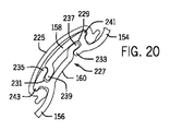
座部281の形状及び外側ローラ250上のその配向は、第2のシェード24の延長を開始するべく座部281からの第2のボトムレール220の円滑な予測可能な係合解除を促進する(図32に示された位置から)。座部281の形状及び配向は、ボトムレール220が座部281から垂直に落下することを可能にし、これは比較的重いボトムレール220への重力を利用する。外側ローラ250上の座部281の概して接線方向の配向がその一助となる。図35を参照すると、上壁277aが、凹部の上縁から下向きに、半径方向内向きにリップ277bに延び、リップ277bは、直下に上側自由縁277cに延びる。座部281のこの部分は最も深い(外側ローラの周縁から中心の方に測定した場合)。下側壁279aは、凹部の下縁から上方に、内向きに浅い角度で延び、スロット276の下側自由縁279cを画定するリップ279bに移行する。下側壁279aは比較的垂直であり、上側リップ277bとの組み合わせにおいても比較的垂直なままである。スロット276の下側自由縁279cは、内側ローラ248上に後退させられる際のこの特徴の上の第2のシェード24の円滑な移動を可能にするべく湾曲している又は丸みをつけられている。   The shape of the seat 281 and its orientation on the outer roller 250 facilitates a smooth and predictable disengagement of the second bottom rail 220 from the seat 281 to initiate the extension of the second shade 24 ( (From the position shown in FIG. 32). The shape and orientation of the seat 281 allows the bottom rail 220 to fall vertically from the seat 281, which utilizes gravity on the relatively heavy bottom rail 220. The general tangential orientation of the seat 281 on the outer roller 250 helps. Referring to FIG. 35, the upper wall 277a extends from the upper edge of the recess downward and radially inward to the lip 277b, and the lip 277b extends directly below the upper free edge 277c. This portion of the seat 281 is deepest (when measured from the periphery of the outer roller toward the center). The lower wall 279a extends upward from the lower edge of the recess at a shallow angle inward and transitions to a lip 279b that defines a lower free edge 279c of the slot 276. The lower wall 279a is relatively vertical and remains relatively vertical in combination with the upper lip 277b. The lower free edge 279c of the slot 276 is curved or rounded to allow smooth movement of the second shade 24 over this feature as it is retracted onto the inner roller 248. .

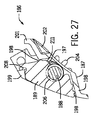
座部281における第2のボトムレール220の確実な係合は、ベアリング271をアンカー溝245から係合解除するためのローラロック255の一貫した作動の一助となる。図31を参照すると、第2のシェード24が内側ローラ248の周りにほぼ十分に巻かれるときに、第2のシェード24のボトムレール220がローラロック255と係合してローラロック255を外側ローラ250の外側から係合解除する。第2のボトムレール220は、図31及び図35に破線で示される。この位置で、第2のボトムレール220の端から軸方向に延びるアクチュエータリム247は、ローラロック255の下側レッグ267上に形成されるピン269と接触する。後退させられている第2のシェード24によって第2のボトムレール220が座部281に引き込まれる際に、アクチュエータリム247がピン269を支柱253のピボット軸に対して動かす。ピン269は、内側ローラ248に対して半径方向内向きに動かされ、ローラロック255のピボット軸に対して周方向に動かされる。支柱253を中心としたローラロック255の移動が上側アーム265を動かして、ベアリング271の上方移動を開始し、アンカー溝245との係合を解除し、外側ローラ250を自由に回転させる(図32、図36、及び図43参照)。   Reliable engagement of the second bottom rail 220 at the seat 281 helps with consistent operation of the roller lock 255 to disengage the bearing 271 from the anchor groove 245. Referring to FIG. 31, when the second shade 24 is wound substantially fully around the inner roller 248, the bottom rail 220 of the second shade 24 engages the roller lock 255 to cause the roller lock 255 to engage the outer roller. The engagement is released from the outside of 250. The second bottom rail 220 is indicated by a broken line in FIGS. 31 and 35. In this position, the actuator rim 247 extending axially from the end of the second bottom rail 220 contacts a pin 269 formed on the lower leg 267 of the roller lock 255. The actuator rim 247 moves the pin 269 relative to the pivot axis of the column 253 when the second bottom rail 220 is pulled into the seat 281 by the second shade 24 being retracted. Pin 269 is moved radially inward relative to inner roller 248 and circumferentially relative to the pivot axis of roller lock 255. The movement of the roller lock 255 around the column 253 moves the upper arm 265 to start the upward movement of the bearing 271 to release the engagement with the anchor groove 245 and freely rotate the outer roller 250 (FIG. 32). , FIG. 36 and FIG. 43).

図42及び図43に示すように、アクチュエータリム247は、ローラロック255に隣接する第2のボトムレール220の端から延びる。図44及び図45を参照すると、リム247は、この例では第2のボトムレール220の下側の湾曲した形状に従う薄い湾曲した要素である。リム247は、第2のボトムレール220の下側と一致する寸法に沿って湾曲し、第2のボトムレール220から離れる方に軸方向に延びる。図43で最もよく分かるように、リム247は、ローラロック255上のピン269と係合するがローラロック255の中央プレート261と接触しないように十分な距離だけ延びる。フィン247の内部の凹面は、ピン269の円形外面と係合する。第2のボトムレール220がさらに後退させられる際に、ピン269とフィン247はスライド係合を維持する。第2の端レール220のこのさらなる移動がローラロック255を支柱253のピボット軸を中心としてさらにピボットさせ、したがってローラロックベアリング271をアンカー溝245の外に動かす。   As shown in FIGS. 42 and 43, the actuator rim 247 extends from the end of the second bottom rail 220 adjacent to the roller lock 255. Referring to FIGS. 44 and 45, the rim 247 is a thin curved element that follows the curved shape of the lower side of the second bottom rail 220 in this example. The rim 247 is curved along a dimension coinciding with the lower side of the second bottom rail 220, and extends in the axial direction away from the second bottom rail 220. As best seen in FIG. 43, the rim 247 extends a sufficient distance to engage the pin 269 on the roller lock 255 but not to contact the central plate 261 of the roller lock 255. The concave surface inside the fin 247 engages with the circular outer surface of the pin 269. As the second bottom rail 220 is further retracted, the pin 269 and the fin 247 maintain sliding engagement. This further movement of the second end rail 220 causes the roller lock 255 to pivot further about the pivot axis of the post 253, thus moving the roller lock bearing 271 out of the anchor groove 245.

図32及び図36を参照すると、第2のシェード24が外側ローラ250にさらに引き込まれる際に、ボトムレール220が座部281に確実に位置付けられ、ベアリング271をアンカー溝245から十分に取り出すのに十分な量だけ内向きにフィン247がピン269を動かし、外側ローラ250が自由に回転する。動作機構240のさらなる作動が、第2のシェード24の張力下で座部281におけるボトムレール220の係合を通じて内側ローラ248の回転運動を外側ローラ250に適用する。この係合が、外側ローラ250を内側ローラ248の回転と連動して回転させる。外側ローラ250が後退方向に回転し始める際に、第2のボトムレール220上のアクチュエータリム247がローラロック255上のピン269から係合解除される。図33及び図37を参照すると、解放されると、ローラロック255が、ばね259によって付勢されて、ベアリング271をアンカー溝245から離間された周方向の場所で外側ローラ250の外面と接触させる。   Referring to FIGS. 32 and 36, when the second shade 24 is further retracted into the outer roller 250, the bottom rail 220 is securely positioned on the seat portion 281, so that the bearing 271 can be sufficiently removed from the anchor groove 245. The fin 247 moves the pin 269 inward by a sufficient amount and the outer roller 250 rotates freely. Further actuation of the motion mechanism 240 applies the rotational motion of the inner roller 248 to the outer roller 250 through the engagement of the bottom rail 220 in the seat 281 under the tension of the second shade 24. This engagement causes the outer roller 250 to rotate in conjunction with the rotation of the inner roller 248. When the outer roller 250 begins to rotate in the reverse direction, the actuator rim 247 on the second bottom rail 220 is disengaged from the pin 269 on the roller lock 255. Referring to FIGS. 33 and 37, when released, the roller lock 255 is biased by the spring 259 to bring the bearing 271 into contact with the outer surface of the outer roller 250 at a circumferential location spaced from the anchor groove 245. .

図34を参照すると、外側ローラ250が後退方向に回転し続ける際に、第1のシェード22が外側ローラ250の周りに巻きつき、アンカー溝245を覆う。外側ローラ250が回転し続ける際にローラロックベアリング271がアンカー溝245に近づくときに、ローラロックベアリング271が、溝245にわたる第1のシェード22上に乗ることによって溝245を通過する。第1のシェード22は、外側ローラ250の周りに巻きつけられる際に張力下にあり、したがって、溝245の上に延びるシェード22を比較的張った状態にする。ベアリング271は、第1のシェード22の一巻きだけがアンカー溝245の上に存在するときには、アンカー溝245の中に若干押し込まれる場合があるが、別のフル回転後には、ベアリング271は、アンカー溝245からの干渉なしに外側ローラ250の周りに巻きつけられた第1のシェード22の表面上に乗る。   Referring to FIG. 34, as the outer roller 250 continues to rotate in the backward direction, the first shade 22 wraps around the outer roller 250 and covers the anchor groove 245. As the roller lock bearing 271 approaches the anchor groove 245 as the outer roller 250 continues to rotate, the roller lock bearing 271 passes through the groove 245 by riding on the first shade 22 across the groove 245. The first shade 22 is under tension as it is wrapped around the outer roller 250, thus leaving the shade 22 extending above the groove 245 relatively tensioned. The bearing 271 may be pushed slightly into the anchor groove 245 when only one turn of the first shade 22 is present on the anchor groove 245, but after another full rotation, the bearing 271 is anchored. Ride on the surface of the first shade 22 wound around the outer roller 250 without interference from the groove 245.

第1のシェード22が後退し続ける際に、第1のシェード22は外側ローラ250の周りに多数回巻きつき、ローラロックベアリング271はシェード22の外面上に乗り続ける。デュアルローラユニット246は、第1のボトムレール18が例えばヘッドレールハウジング上に当接して接触するときに、上側後退位置に到達する。上側後退位置を画定するために、下側制限止め部とは反対の制限ねじ266上に位置付けられる上側制限止め部を含む他の機構が用いられてもよいと考えられる。上記の説明のように、十分に延長された位置からの第2のシェード24及び第1のシェード22の後退は、ユーザが両方のシェード22、24を後退させるための1つの動作要素を(手動で又は自動的に)作動する状態で起こることができる。制限ねじ266は、制限ナット268が下側制限止め部から上側後退位置に到達するまで動くことを可能にするのに十分な長さである。   As the first shade 22 continues to retract, the first shade 22 wraps around the outer roller 250 many times, and the roller lock bearing 271 continues to ride on the outer surface of the shade 22. The dual roller unit 246 reaches the upper retreat position when the first bottom rail 18 comes into contact with, for example, the head rail housing. It is contemplated that other mechanisms may be used to define an upper retracted position, including an upper limit stop positioned on a limit screw 266 opposite the lower limit stop. As described above, the retraction of the second shade 24 and the first shade 22 from the fully extended position provides one operating element (manual for the user to retract both shades 22, 24). Or automatically). Limit screw 266 is long enough to allow limit nut 268 to move from the lower limit stop until it reaches the upper retracted position.

第1のシェード22及び第2のシェード24の延長は、望まれる場合には、例えば概して図34〜図30に従う上述の順序と逆の順序で達成される。これは、ユーザが(十分な後退と十分な延長との間で)第1のシェード22だけを延長させるか又は第2のシェード24も延長させるかを選択することを可能にする。第1のシェード22の延長中に、ユーザが動作機構240を作動させて内側ローラ248を延長方向(図34〜図30では時計回り)に回転させ、これにより、外側ローラ250が延長方向に回転する。デュアルローラユニット246は、この例では、ユーザが内側ローラ248を回転するように制御する方向に回転する。第1のシェード22を外側ローラ250の後側から延長する際に、ローラロックベアリング271が、第1のシェード22がほぼ十分に延長されるまで外側ローラ250の外面上に乗る。この時点で、外側ローラ250の外面が露出される。   Extension of the first shade 22 and the second shade 24 is accomplished, if desired, in an order opposite to that described above, eg, generally according to FIGS. This allows the user to choose between extending only the first shade 22 (between sufficient retraction and sufficient extension) or the second shade 24 as well. During the extension of the first shade 22, the user operates the operating mechanism 240 to rotate the inner roller 248 in the extending direction (clockwise in FIGS. 34 to 30), whereby the outer roller 250 rotates in the extending direction. To do. In this example, the dual roller unit 246 rotates in a direction in which the user controls the inner roller 248 to rotate. When extending the first shade 22 from the rear side of the outer roller 250, the roller lock bearing 271 rides on the outer surface of the outer roller 250 until the first shade 22 is substantially fully extended. At this point, the outer surface of the outer roller 250 is exposed.

外側ローラ250が回転し続ける際に、ローラロックベアリング271は、アンカー溝245に出会うまで外側ローラ250の外面に乗る。ベアリング271は、ばね259によって下向きに付勢されて溝245に入り、外側ローラ250の回転を抑制し、内側ローラ248の継続した回転を可能にする(ユーザによって望まれる場合)。ローラロック255が外側ローラ250の外面に接触する方向に付勢されるので、ベアリング271がさらなる付勢なしにアンカー溝245に動く。この時点で、第1のシェード22は開口部にわたるその最も延長された位置にある。ローラロック255は、これらの例ではばね259以外の手段によって付勢されてもよいと考えられる。例えば、ローラロック255の上側アーム273は、ローラロック255が上側アーム273の重量の下で要望に応じて自動的にピボットするように重くされてもよい。ばね259が用いられる場合、これは、ワイヤばね、コイルばね、弾性材料ばねなど(ゴム、弾性、及び/又はプラスチックなど)であってもよい。   As the outer roller 250 continues to rotate, the roller lock bearing 271 rides on the outer surface of the outer roller 250 until it meets the anchor groove 245. The bearing 271 is biased downward by the spring 259 and enters the groove 245 to inhibit rotation of the outer roller 250 and allow continued rotation of the inner roller 248 (if desired by the user). Since the roller lock 255 is biased in a direction to contact the outer surface of the outer roller 250, the bearing 271 moves into the anchor groove 245 without further bias. At this point, the first shade 22 is in its most extended position across the opening. It is contemplated that the roller lock 255 may be biased by means other than the spring 259 in these examples. For example, the upper arm 273 of the roller lock 255 may be heavy so that the roller lock 255 automatically pivots as desired under the weight of the upper arm 273. If a spring 259 is used, this may be a wire spring, a coil spring, an elastic material spring, etc. (such as rubber, elasticity, and / or plastic).

ローラロック255のベアリング271がアンカー溝245に着座されるときに、外側ローラ250のスロット276が、動作システム240によって第2のシェード24の張力が緩和されるときに第2のシェード24のボトムレール220が座部281から垂直に落下し得るように、ヘッドレール14内で回転して配向される。比較的垂直なベース壁284を備える座部281の概して接線方向の配向及び概して垂直な位置付けにより、後退位置において第2のシェード24の張力が解放されるときに第2のボトムレール220の重量がボトムレール220を座部281から引き出すのに効果的となる。しかしながら、ユーザが第2のシェード24を延長することを意図しない場合、第2のシェード24は後退させられたままであってもよい。動作機構240は、第2のシェード24又は第1のシェード22の望ましくない下方移動を制約するためにブレーキシステムを含むことができる。   When the bearing 271 of the roller lock 255 is seated in the anchor groove 245, the slot 276 of the outer roller 250 causes the bottom rail of the second shade 24 when the tension of the second shade 24 is relieved by the operating system 240. It is rotated and oriented in the head rail 14 so that 220 can fall vertically from the seat 281. Due to the generally tangential orientation and generally vertical positioning of the seat 281 with the relatively vertical base wall 284, the weight of the second bottom rail 220 when the tension of the second shade 24 is released in the retracted position. This is effective for pulling out the bottom rail 220 from the seat portion 281. However, if the user does not intend to extend the second shade 24, the second shade 24 may remain retracted. The operating mechanism 240 can include a brake system to constrain undesired downward movement of the second shade 24 or the first shade 22.

第2のシェード24を延長するために、動作システム240がユーザによって望まれるレベルにさらに作動される。ユーザが第2のシェード24を最下位置(最延長)に延長する時に、制限ナット268は、下側限界止め部と係合して制限ねじ266上に位置付けられる。したがって、外側ローラ250に取り付けられる後退された第1のシェード22の上側限界を画定し、かつ、内側ローラ248に取り付けられる延長された第2のシェード24の下側限界を画定するために、単一の制限ねじ266が用いられてもよい。   To extend the second shade 24, the operating system 240 is further activated to a level desired by the user. When the user extends the second shade 24 to its lowest position (extension), the limit nut 268 engages the lower limit stop and is positioned on the limit screw 266. Thus, to define the upper limit of the retracted first shade 22 attached to the outer roller 250 and to define the lower limit of the extended second shade 24 attached to the inner roller 248. One limiting screw 266 may be used.

図30〜図34の第1のシェード22(図1〜図5に示されたものと同じ又は異なる場合がある)は、外側ローラ250の前側に巻きつけられ又はそこから繰り出されてもよいと考えられる。前側が下降するシェード構造体に適用される場合のデュアルローラシェード技術の実装を容易にするために、本明細書で説明される構造体への付随する修正が必要とされるであろう。ローラロック機構及びこれを動作させるのに必要な付随する要素は、ヘッドレールの左端上のローラロック機構と併せて又はそれだけで、右端キャップ226aと共同してヘッドレールの右端上で使用されてもよいことも意図される。また、第2のボトムレール220は、そのいずれかの端上に作動リム247を有してもよい。   The first shade 22 of FIGS. 30-34 (which may be the same as or different from that shown in FIGS. 1-5) may be wound around or fed out of the front side of the outer roller 250. Conceivable. Concomitant modifications to the structures described herein will be required to facilitate the implementation of the dual roller shade technique when applied to shade structures that are lowered on the front side. The roller locking mechanism and the accompanying elements necessary to operate it may be used on the right end of the head rail in conjunction with or alone with the roller locking mechanism on the left end of the head rail in conjunction with the right end cap 226a. It is also intended to be good. The second bottom rail 220 may also have an operating rim 247 on either end thereof.

上記の説明は広い用途を有する。提供される例は影絵型シェード及び暗幕型シェードを説明するが、本明細書で開示される概念は、多くのタイプのシェードに等しくあてはめてもよいことを理解されたい。したがって、どのような実施形態の説明も説明となることをだけを意図しており、請求項を含む本開示の範囲がこれらの例に限定されることを示唆することを意図していない。言い換えれば、本開示の例示的な実施形態が本明細書で詳細に説明されているが、発明概念が他の方法で様々に具体化され、採用されてもよいことと、付属の請求項が、従来技術によって限定されるものを除いて、こうしたバリエーションを含むように解釈されることを意図していること理解される。   The above description has wide application. While the examples provided illustrate shadow shades and shader shades, it should be understood that the concepts disclosed herein may be equally applied to many types of shades. Accordingly, the description of any embodiment is intended to be illustrative only and is not intended to suggest that the scope of the disclosure, including the claims, is limited to these examples. In other words, while exemplary embodiments of the present disclosure have been described in detail herein, the inventive concept may be variously embodied and employed in other ways, and the appended claims It is understood that it is intended to be construed to include such variations, except as limited by the prior art.

上記の説明は、例証及び説明する目的で提示されており、本開示を本明細書で開示された1つ又は複数の形態に限定することを意図していない。例えば、本開示の種々の特徴が、本開示を合理化する目的で1つ以上の態様、実施形態、又は構成において一緒にグループ化される。しかしながら、本開示の或る態様、実施形態、又は構成の種々の特徴は、代替の態様、実施形態、又は構成において組み合わされてもよいことを理解されたい。さらに、以下の請求項は、この言及によってこの詳細な説明にここで組み込まれ、各請求項は、本開示の別個の実施形態として独立している。   The above description has been presented for purposes of illustration and description, and is not intended to limit the present disclosure to the form or forms disclosed herein. For example, various features of the present disclosure are grouped together in one or more aspects, embodiments, or configurations for the purpose of streamlining the present disclosure. However, it should be understood that various features of certain aspects, embodiments, or configurations of the present disclosure may be combined in alternative aspects, embodiments, or configurations. Furthermore, the following claims are hereby incorporated into this detailed description by this reference, with each claim standing on its own as a separate embodiment of this disclosure.

本明細書で用いられる場合の「少なくとも1つ」、「1つ以上の」、及び「及び/又は」という文言は、運用での接続詞と離接接続詞との両方である制約のない(open−ended)表現である。   As used herein, the terms “at least one”, “one or more”, and “and / or” are unrestricted (both open and disjunctive conjunctions). end) expression.

本明細書で用いられる場合の「a」又は「an」エンティティという用語は、そのエンティティのうちの1つ以上を指す。したがって、「a」(又は「an」)、「1つ以上の」、及び「少なくとも1つ」という用語は、本明細書では交換可能に用いることができる。   The term “a” or “an” entity as used herein refers to one or more of the entities. Thus, the terms “a” (or “an”), “one or more”, and “at least one” can be used interchangeably herein.

すべての方向の言及(例えば、近位、遠位、上、下、上方、下方、左、右、横、長手方向、前、後ろ、上部、下部、よりも上、よりも下、垂直、水平、半径方向、軸方向、時計回り、及び反時計回り)は、本開示の読者の理解を助けるべく識別の目的でのみ用いられ、特に、位置、配向、又は本開示の使用についての制限を生み出さない。接続の言及(例えば、取り付けられる、結合される、接続される、及び接合される)は、広く解釈されるべきであり、他に指定のない限り、要素の集合の間の中間部材、及び、要素間の相対運動を含むことができる。したがって、接続の言及は、2つの要素が直接接続され、互いに固定の関係にあることを必ずしも暗示していない。識別の言及(例えば、一次、二次、第1の、第2の、第3の、第4のなど)は、重要性又は優先順位を意味することを意図していないが、1つの特徴を別の特徴から区別するのに用いられる。図面は、単に例示するためであって、添付の図面に示される寸法、位置、順序、及び相対的サイズは変えてもよい。   All direction references (eg, proximal, distal, top, bottom, top, bottom, left, right, sideways, longitudinal, front, back, top, bottom, above, below, vertical, horizontal (Radial, axial, clockwise, and counterclockwise) are used for identification purposes only to help the reader of the present disclosure and in particular create restrictions on position, orientation, or use of the present disclosure. Absent. References to connections (eg, attached, joined, connected, and joined) are to be interpreted broadly, and unless specified otherwise, intermediate members between sets of elements, and Relative motion between elements can be included. Thus, reference to a connection does not necessarily imply that the two elements are directly connected and in a fixed relationship with each other. Identification references (eg, primary, secondary, first, second, third, fourth, etc.) are not intended to imply importance or priority, Used to distinguish from other features. The drawings are for illustrative purposes only and the dimensions, positions, order and relative sizes shown in the accompanying drawings may vary.

Claims (15)

建築物の開口部のための覆いであって、
中央縦軸と側壁に形成される細長いスロットとを有する外側ローラと、
央縦軸を有する内側ローラと、
前記外側ローラに固定され、前記外側ローラの周りに巻きつけられるように適合された第1のシェードと、
第2のボトムレールを画定し、前記内側ローラに固定され、前記内側ローラの周りに巻きつけられるように適合された、第2のシェードと、
前記内側ローラは前記外側ローラ内に受け入れられ、
前記内側ローラの中央縦軸を中心とした回転移動のために前記内側ローラ及び前記外側ローラを支持するマウンティングシステムと、
前記第2のシェードは、前記細長いスロットを通して延び、前記細長いスロットを通して前記内側ローラ上に後退可能、かつ前記内側ローラから延長可能であり、前記第2のボトムレールは前記第2のシェードが十分に後退された位置にあるときに前記外側ローラと係合し、
前記内側ローラを選択的に回転させるための動作機構と
を備え、
前記後退位置にあるときの前記内側ローラの回転が前記外側ローラを回転させる、
前記第2のシェードが、前記内側ローラの端及び前記外側ローラの端と位置合わせされる側縁を有する、
前記外側ローラが、それぞれ長手方向に延びる末端縁を有する、第1のシェル及び第2のシェルを含み、
前記第1のシェル及び第2のシェルの前記長手方向に延びる末端縁が、前記細長いスロットを画定するべく互いから周方向に離間される、
覆い。
A cover for an opening in a building,
An outer roller having a central longitudinal axis and an elongated slot formed in the sidewall;
An inner roller having a medium Hisashitate shaft,
A first shade secured to the outer roller and adapted to be wrapped around the outer roller;
A second shade defining a second bottom rail, secured to the inner roller and adapted to be wrapped around the inner roller;
The inner roller is received in the outer roller;
A mounting system that supports the inner and outer rollers for rotational movement about a central longitudinal axis of the inner roller;
The second shade extends through the elongated slot, is retractable onto the inner roller through the elongated slot, and is extendable from the inner roller, and the second bottom rail is sufficiently secured by the second shade. Engaging the outer roller when in the retracted position;
An operation mechanism for selectively rotating the inner roller,
Rotation of the inner roller when in the retracted position rotates the outer roller;
The second shade has side edges aligned with ends of the inner and outer rollers;
The outer roller includes a first shell and a second shell, each having a longitudinally extending distal edge;
The longitudinally extending distal edges of the first and second shells are circumferentially spaced from each other to define the elongated slot;
Cover.
前記細長いスロットが前記外側ローラの端間に延び、
前記内側ローラが前記外側ローラの端と位置合わせされる端を有する、
請求項1に記載の覆い。
The elongated slot extends between the ends of the outer roller;
The inner roller has an end aligned with an end of the outer roller;
The covering according to claim 1.
前記外側ローラの回転を制約する第1の位置と前記外側ローラの回転を可能にする第2の位置との間で移動可能なロック機構
を備え、
前記ロック機構が、前記第2のボトムレールが前記ロック機構と係合すると前記第1の位置から前記第2の位置に移動する、
請求項1または請求項2に記載の覆い。
A lock mechanism movable between a first position that restricts rotation of the outer roller and a second position that allows rotation of the outer roller;
The locking mechanism moves from the first position to the second position when the second bottom rail engages the locking mechanism;
Cover according to claim 1 or claim 2.
前記スロットが、前記第1のシェードの延長方向に直交して配向される、請求項1〜のいずれか1項に記載の覆い。 The covering according to any one of claims 1 to 3 , wherein the slot is oriented perpendicular to an extending direction of the first shade. 前記外側ローラが、前記スロットに沿って形成される長手方向の座部を画定し、
前記第2のボトムレールが、前記内側ローラが後退位置にあるときに前記座部に受け入れられる、
請求項1〜のいずれか1項に記載の覆い。
The outer roller defines a longitudinal seat formed along the slot;
The second bottom rail is received in the seat when the inner roller is in a retracted position;
The covering according to any one of claims 1 to 4 .
前記長手方向の座部が、前記第1のシェードの延長方向口を有する凹部を画定する、請求項に記載の覆い。 It said longitudinal seat defines a recess having an open mouth in the extending direction of the first shade, covering of claim 5. 前記外側ローラが、前記側壁に形成される細長い溝を画定し、
前記ロック機構がベアリングを含み、
前記ロック機構の第1の位置において、前記ベアリングが前記溝に受け入れられる、
請求項に記載の覆い。
The outer roller defines an elongated groove formed in the sidewall;
The locking mechanism includes a bearing;
The bearing is received in the groove in a first position of the locking mechanism;
The covering according to claim 3 .
前記ロック機構がピンを含み、
前記第2のボトムレールによる前記ピンの係合で前記ロック機構が作動され、前記ベアリングが前記溝から取り出される、請求項に記載の覆い。
The locking mechanism includes a pin;
The cover according to claim 7 , wherein the locking mechanism is activated by the engagement of the pin by the second bottom rail, and the bearing is removed from the groove.
前記ベアリングが前記第2の位置で前記外側ローラの外面と移動可能に係合する、請求項又は請求項に記載の覆い。 9. A cover as claimed in claim 7 or claim 8 , wherein the bearing is movably engaged with an outer surface of the outer roller in the second position. 前記ロック機構が、前記第1の位置と前記第2の位置との間でピボットするロック部材を含む、請求項1〜のいずれか1項に記載の覆い。 The locking mechanism, wherein the first position comprises a locking member to pivot and a second position, covering according to any one of claims 1-9. 前記ロック機構が、前記第1の位置と前記第2の位置との間で軸方向に平行移動するロック部材を含む、請求項1〜10のいずれか1項に記載の覆い。 The locking mechanism, wherein the first position comprises a locking member which moves parallel to the axial direction between the second position, covering according to any one of claims 1-10. 前記ロック機構が、前記外側ローラの外部に位置付けられ、前記内側ローラの中央縦軸に実質的に平行に配向される、回転可能なシャフトを含む、
請求項1〜11のいずれか1項に記載の覆い。
The locking mechanism includes a rotatable shaft positioned outside the outer roller and oriented substantially parallel to a central longitudinal axis of the inner roller;
The covering according to any one of claims 1 to 11 .
前記ロック機構がハウジングを含み、
前記回転可能なシャフトが前記ハウジングにジャーナル式に取り付けられる、
請求項12に記載の覆い。
The locking mechanism includes a housing;
The rotatable shaft is journaled to the housing;
The covering according to claim 12 .
端キャップをさらに備え、前記ハウジングが前記端キャップから片持ちにされる、請求項13に記載の覆い。 The covering of claim 13 , further comprising an end cap, wherein the housing is cantilevered from the end cap. 前記ロック機構が、前記回転可能なシャフト及び前記外側ローラの回転を結合する歯車機構を含む、請求項1214のいずれか1項に記載の覆い。

The cover according to any one of claims 12 to 14 , wherein the locking mechanism includes a gear mechanism that couples rotation of the rotatable shaft and the outer roller.

JP2016519651A 2013-06-12 2014-06-12 Cover for building openings with nested rollers Multiple roller cover for building openings Active JP6431053B2 (en)

Priority Applications (1)

Application Number Priority Date Filing Date Title
JP2018206543A JP6889140B2 (en) 2013-06-12 2018-11-01 Covers for building openings with nested rollers Multiple roller covers for building openings

Applications Claiming Priority (7)

Application Number Priority Date Filing Date Title
US201361834080P 2013-06-12 2013-06-12
US61/834,080 2013-06-12
US14/213,449 2014-03-14
US14/212,387 2014-03-14
US14/212,387 US9567802B2 (en) 2013-03-15 2014-03-14 Covering for an architectural opening having nested rollers
US14/213,449 US9945177B2 (en) 2013-03-15 2014-03-14 Covering for an architectural opening having nested rollers
PCT/US2014/042131 WO2014201253A2 (en) 2013-06-12 2014-06-12 Covering for an architectural opening having nested rollers

Related Child Applications (1)

Application Number Title Priority Date Filing Date
JP2018206543A Division JP6889140B2 (en) 2013-06-12 2018-11-01 Covers for building openings with nested rollers Multiple roller covers for building openings

Publications (2)

Publication Number Publication Date
JP2016524062A JP2016524062A (en) 2016-08-12
JP6431053B2 true JP6431053B2 (en) 2018-11-28

Family

ID=52022942

Family Applications (2)

Application Number Title Priority Date Filing Date
JP2016519651A Active JP6431053B2 (en) 2013-06-12 2014-06-12 Cover for building openings with nested rollers Multiple roller cover for building openings
JP2018206543A Active JP6889140B2 (en) 2013-06-12 2018-11-01 Covers for building openings with nested rollers Multiple roller covers for building openings

Family Applications After (1)

Application Number Title Priority Date Filing Date
JP2018206543A Active JP6889140B2 (en) 2013-06-12 2018-11-01 Covers for building openings with nested rollers Multiple roller covers for building openings

Country Status (12)

Country Link
EP (2) EP3333352B1 (en)
JP (2) JP6431053B2 (en)
KR (1) KR102318961B1 (en)
CN (2) CN105378205B (en)
AU (2) AU2014278079B2 (en)
CA (1) CA2915204C (en)
DK (1) DK3333352T3 (en)
HK (1) HK1216187A1 (en)
MX (1) MX366645B (en)
PL (1) PL3333352T3 (en)
TW (3) TWI693335B (en)
WO (1) WO2014201253A2 (en)

Families Citing this family (13)

* Cited by examiner, † Cited by third party
Publication number Priority date Publication date Assignee Title
US9945177B2 (en) 2013-03-15 2018-04-17 Hunter Douglas Inc. Covering for an architectural opening having nested rollers
US9567802B2 (en) 2013-03-15 2017-02-14 Hunter Douglas Inc. Covering for an architectural opening having nested rollers
WO2014143057A1 (en) 2013-03-15 2014-09-18 Hunter Douglas Inc. Position lock for roller supported architectural coverings
US9322210B2 (en) * 2013-08-19 2016-04-26 Comfortex Window Fashions Cordless fabric venetian window shade assembly
KR101359513B1 (en) 2013-08-27 2014-02-07 곽재석 Dual fabric blind fabric angle adjustment device
US9702187B2 (en) 2015-02-13 2017-07-11 Hunter Douglas Inc. Covering for an architectural opening having nested tubes
KR101659926B1 (en) * 2016-04-12 2016-09-27 (주)한국윈텍 Under structure of blind apparatus and blind apparatus having the same
CN107842303B (en) * 2016-09-19 2020-03-13 德侑股份有限公司 Window shade and actuating system thereof
TWI767005B (en) 2017-06-01 2022-06-11 美商漢特道格拉斯股份有限公司 Covering for an architectural feature having a bottom rail leveling mechanism
JP7041954B2 (en) * 2018-05-11 2022-03-25 株式会社 Wis Dimmable roll screen and its manufacturing method
CN109488186A (en) * 2018-08-16 2019-03-19 朗丝窗饰有限公司 A kind of Shangri-la curtain and its underbeam
CN109434801B (en) * 2018-10-15 2022-02-22 斯图加特航空自动化(青岛)有限公司 Sand-blasting zinc-spraying robot moving mechanism and sand-blasting zinc-spraying equipment
CZ308287B6 (en) * 2018-10-29 2020-04-15 Bestadom, s.r.o. Roller shutter mechanism

Family Cites Families (15)

* Cited by examiner, † Cited by third party
Publication number Priority date Publication date Assignee Title
US3285325A (en) * 1964-03-19 1966-11-15 Ametek Inc Actuator for retractable wall
JPH0567797U (en) * 1990-12-28 1993-09-10 株式会社ウエノ Multipurpose roller screen
US5647421A (en) * 1995-06-06 1997-07-15 Hunter Douglas Inc. Dual shape assembly
US7549455B2 (en) * 2003-08-20 2009-06-23 Hunter Douglas Inc. Retractable shade with collapsible vanes
US7051782B2 (en) * 2003-10-23 2006-05-30 Lutron Electronics Co., Inc. System for coupling roller shade tubes
CN2646364Y (en) * 2003-10-24 2004-10-06 亿丰综合工业股份有限公司 Double layer roller shutter with front and rear curtain piece keeping level and close
ITTV20050024U1 (en) * 2005-05-06 2006-11-07 Nice Spa END-RIDE DEVICE FOR ROLLER SHUTTERS OR SOLAR PROTECTION DEVICES.
US7740044B2 (en) * 2006-08-31 2010-06-22 Dometic, LLC Awning assembly including drop-down shade
JP4017040B1 (en) * 2007-05-09 2007-12-05 ナビオ株式会社 Winding device and screen device
GB2470387A (en) * 2009-05-21 2010-11-24 Brian John Howard Hughes Roller blind
KR100943408B1 (en) * 2009-11-28 2010-02-19 곽재석 A double fabric blind
US8365797B2 (en) * 2010-04-30 2013-02-05 Hunter Douglas Inc. Cord tension control for top down/bottom up covering for architectural openings
TWI445878B (en) * 2010-07-01 2014-07-21 Blinds with a looped blind sheet for adjusting opacity
JP6145093B2 (en) * 2011-08-26 2017-06-07 ハンター・ダグラス・インコーポレーテッド Cordless retractable roller shade for window covering
JP6271186B2 (en) * 2012-11-08 2018-01-31 花王株式会社 Absorbent articles

Also Published As

Publication number Publication date
MX2015016938A (en) 2016-08-08
JP6889140B2 (en) 2021-06-18
CN107524403A (en) 2017-12-29
DK3333352T3 (en) 2020-01-06
KR20160019923A (en) 2016-02-22
AU2014278079B2 (en) 2018-05-24
TWI693335B (en) 2020-05-11
HK1216187A1 (en) 2016-10-21
CA2915204C (en) 2021-10-19
PL3333352T3 (en) 2020-05-18
TW201510346A (en) 2015-03-16
BR112015030821A2 (en) 2017-07-25
BR112015030821A8 (en) 2020-01-21
CN107524403B (en) 2019-12-06
CN105378205A (en) 2016-03-02
AU2018217231B2 (en) 2020-10-22
WO2014201253A3 (en) 2015-02-26
JP2019035322A (en) 2019-03-07
TW201839248A (en) 2018-11-01
TWI742428B (en) 2021-10-11
EP3333352A1 (en) 2018-06-13
JP2016524062A (en) 2016-08-12
EP3008273A4 (en) 2017-04-19
WO2014201253A2 (en) 2014-12-18
EP3008273B1 (en) 2018-09-26
EP3333352B1 (en) 2019-10-16
MX366645B (en) 2019-07-17
AU2018217231A1 (en) 2018-08-30
TWI640683B (en) 2018-11-11
EP3008273A2 (en) 2016-04-20
TW202003996A (en) 2020-01-16
CN105378205B (en) 2017-09-29
KR102318961B1 (en) 2021-10-27
CA2915204A1 (en) 2014-12-18
AU2014278079A1 (en) 2015-12-24

Similar Documents

Publication Publication Date Title
JP6431053B2 (en) Cover for building openings with nested rollers Multiple roller cover for building openings
US11643870B2 (en) Covering for an architectural opening having nested rollers
US9945177B2 (en) Covering for an architectural opening having nested rollers
US10641040B2 (en) Covering for an architectural opening having nested tubes
US10415305B2 (en) Window shade
JP2018204426A (en) Cover for architectural features with horizontal mechanism of bottom rail
BR112015030821B1 (en) COVERAGE FOR AN ARCHITECTURE OPENING

Legal Events

Date Code Title Description
A621 Written request for application examination

Free format text: JAPANESE INTERMEDIATE CODE: A621

Effective date: 20170608

A977 Report on retrieval

Free format text: JAPANESE INTERMEDIATE CODE: A971007

Effective date: 20180305

A131 Notification of reasons for refusal

Free format text: JAPANESE INTERMEDIATE CODE: A131

Effective date: 20180424

A521 Request for written amendment filed

Free format text: JAPANESE INTERMEDIATE CODE: A523

Effective date: 20180719

TRDD Decision of grant or rejection written
A01 Written decision to grant a patent or to grant a registration (utility model)

Free format text: JAPANESE INTERMEDIATE CODE: A01

Effective date: 20181002

A61 First payment of annual fees (during grant procedure)

Free format text: JAPANESE INTERMEDIATE CODE: A61

Effective date: 20181101

R150 Certificate of patent or registration of utility model

Ref document number: 6431053

Country of ref document: JP

Free format text: JAPANESE INTERMEDIATE CODE: R150

R250 Receipt of annual fees

Free format text: JAPANESE INTERMEDIATE CODE: R250

R250 Receipt of annual fees

Free format text: JAPANESE INTERMEDIATE CODE: R250

R250 Receipt of annual fees

Free format text: JAPANESE INTERMEDIATE CODE: R250