JP6427323B2 - Substrate drying apparatus and substrate drying method - Google Patents
Substrate drying apparatus and substrate drying method Download PDFInfo
- Publication number
- JP6427323B2 JP6427323B2 JP2014035093A JP2014035093A JP6427323B2 JP 6427323 B2 JP6427323 B2 JP 6427323B2 JP 2014035093 A JP2014035093 A JP 2014035093A JP 2014035093 A JP2014035093 A JP 2014035093A JP 6427323 B2 JP6427323 B2 JP 6427323B2
- Authority
- JP
- Japan
- Prior art keywords
- substrate
- drying
- unit
- heating
- drying auxiliary
- Prior art date
- Legal status (The legal status is an assumption and is not a legal conclusion. Google has not performed a legal analysis and makes no representation as to the accuracy of the status listed.)
- Active
Links
Images


Landscapes
- Drying Of Solid Materials (AREA)
- Cleaning Or Drying Semiconductors (AREA)
Description
この発明は、半導体基板、フォトマスク用ガラス基板、液晶表示用ガラス基板、プラズマ表示用ガラス基板、FED(Field Emission Display)用基板、光ディスク用基板、磁気ディスク用基板、光磁気ディスク用基板などの各種基板(以下、単に「基板」と記載する)に付着した液体を基板から除去する基板乾燥装置および基板乾燥方法に関するものである。 The present invention relates to semiconductor substrates, glass substrates for photomasks, glass substrates for liquid crystal displays, glass substrates for plasma displays, substrates for FED (Field Emission Display), substrates for optical disks, substrates for magnetic disks, substrates for magneto-optical disks, etc. The present invention relates to a substrate drying apparatus and a substrate drying method for removing a liquid attached to various substrates (hereinafter simply referred to as “substrate”) from a substrate.
半導体装置や液晶表示装置などの電子部品の製造工程では、液体を使用する様々な湿式処理を基板に対して施した後、湿式処理によって基板に付着した液体を除去するための乾燥処理を基板に対して施す。 In the process of manufacturing an electronic component such as a semiconductor device or a liquid crystal display device, the substrate is subjected to various wet processes using a liquid to the substrate, and then the substrate is subjected to a drying process for removing the liquid adhering to the substrate by the wet process. Apply to.
湿式処理としては、基板表面の汚染物質を除去する洗浄処理が挙げられる。例えば、ドライエッチング工程により、凹凸を有する微細なパターンを形成した基板表面には、反応副生成物(エッチング残渣)が存在している。また、エッチング残渣の他に、基板表面には金属不純物や有機汚染物質などが付着している恐れがあり、これらの物質を除去するために、基板へ洗浄液を供給するなどの洗浄処理を行う。 Wet processing includes cleaning processing for removing contaminants on the substrate surface. For example, reaction by-products (etching residues) are present on the substrate surface on which a fine pattern having asperities is formed by a dry etching process. In addition to the etching residue, metal impurities and organic contaminants may adhere to the surface of the substrate. In order to remove these substances, cleaning treatment such as supplying a cleaning liquid to the substrate is performed.
洗浄処理の後には、洗浄液をリンス液により除去するリンス処理と、リンス液を乾燥する乾燥処理が施される。リンス処理としては、洗浄液が付着した基板表面に対して脱イオン水(DIW:Deionized Water)などのリンス液を供給し、基板表面の洗浄液を除去するリンス処理が挙げられる。リンス処理の後、必要に応じて、基板表面のリンス液をイソプロピルアルコール(IPA)などの置換液によって除去する置換処理を行うこともある(特許文献1)。その後、リンス液または置換液を除去することにより基板を乾燥させる乾燥処理を行う。 After the cleaning process, a rinse process for removing the cleaning solution with a rinse solution and a drying process for drying the rinse solution are performed. As the rinse process, a rinse solution such as deionized water (DIW: Deionized Water) may be supplied to the substrate surface to which the cleaning solution is attached to remove the cleaning solution on the substrate surface. After the rinse treatment, if necessary, a replacement treatment may be performed in which the rinse solution on the substrate surface is removed by a replacement solution such as isopropyl alcohol (IPA) (Patent Document 1). Thereafter, the substrate is dried by removing the rinse solution or the replacement solution.
近年、基板に形成されるパターンの微細化に伴い、凹凸を有するパターンの凸部におけるアスペクト比(パターン凸部における高さと幅の比)が大きくなってきている。このため、乾燥処理時において、パターンの凹部に入り込んだ洗浄液やリンス液などの液体と、液体に接する気体との境界面に働く表面張力が、パターン中で隣接する凸部を引き寄せて、パターンを倒壊させるという問題があった。 In recent years, with the miniaturization of the pattern formed on the substrate, the aspect ratio (the ratio of the height to the width of the pattern convex portion) in the convex portion of the pattern having the unevenness has been increased. Therefore, during the drying process, the surface tension acting on the interface between the liquid in contact with the liquid such as the cleaning liquid and the rinse liquid that entered into the concave part of the pattern and the gas in contact with the liquid attracts the adjacent convex part in the pattern. There was a problem of collapsing.
このような表面張力に起因するパターンの倒壊を防ぐために、パターンの凹部に入り込んだ液体を凝固や析出により固体にする処理を施して、固体から気体へ昇華させて基板乾燥を行う技術が知られている。固体と、固体に接する気体との境界面には表面張力が働かないため、表面張力に起因するパターンの倒壊を防止することができる。特許文献2には、基板上の液体を凝固させて凍結膜とし、基板および凍結膜よりも低温で、かつ凍結膜の温度よりも低い露点を有するガスを供給することで、凍結膜を昇華させる乾燥技術が示されている。特許文献3には、基板上に昇華性物質の溶液を供給し、溶液中の溶媒を乾燥させて基板上を固相の昇華性物質で満たし、昇華性物質の昇華温度よりも高い温度に基板を加熱することで、昇華性物質を昇華させる乾燥技術が示されている。
In order to prevent the collapse of the pattern caused by such surface tension, there is known a technique of subjecting the liquid that has entered the recess of the pattern to a solid by coagulation or precipitation, and sublimating the solid to a gas to dry the substrate. ing. Since surface tension does not act on the interface between the solid and the gas in contact with the solid, collapse of the pattern due to surface tension can be prevented. In
特許文献2の乾燥技術では、基板表面における凍結膜を昇華させる際に、凍結膜が液体に戻るのを防止するため、凍結膜の凝固点よりも低い温度の乾燥用気体を継続して供給する必要がある。低温の乾燥用気体の消費量は、基板上の凍結膜を除去するための昇華処理時間に依存し、昇華処理時間は、単位時間あたりに凍結膜が昇華する昇華量(凍結膜の昇華速度)を増加することにより短縮することができる。
In the drying technique of
凍結膜の昇華速度は、凍結膜における凍結体の昇華圧と、乾燥用気体における凍結体の分圧との差分に比例し、この差分が大きいほど昇華速度は速くなり、昇華処理時間は短くなる。凍結体の昇華圧は、凍結膜の温度が高くなるにつれて高くなる。しかしながら、特許文献2において、凍結膜は、昇華を利用するため、凍結体の凝固点よりも低い温度に保つ必要がある。したがって、凍結体の昇華圧は、凍結体の凝固点の温度で最大値となり、昇華処理時間の短縮が困難となる。よって、特許文献2の乾燥技術では、生産効率を向上させられないことや、低温の乾燥用気体の消費量を削減できないことが課題となっている。
The sublimation rate of the frozen film is proportional to the difference between the sublimation pressure of the frozen body in the frozen film and the partial pressure of the frozen body in the drying gas, and the larger the difference, the faster the sublimation rate and the shorter the sublimation treatment time . The sublimation pressure of the frozen body increases as the temperature of the frozen film increases. However, in
特許文献3の乾燥技術は、基板表面における昇華性物質を加熱により昇華させて除去することによって、基板表面を乾燥させる技術である。昇華性物質を昇華させるためには熱エネルギーを昇華性物質へ与えることが必要となる。基板上の昇華性物質を全て昇華させるために必要な熱エネルギーの総量は、昇華性物質が吸収する顕熱と潜熱の総量となり、これらは使用する昇華性物質の種類と量に依存する。 The drying technique of Patent Document 3 is a technique for drying the substrate surface by removing the sublimation substance on the substrate surface by heating and removing it. In order to sublimate the sublimable substance, it is necessary to apply thermal energy to the sublimable substance. The total amount of thermal energy required to sublimate all of the sublimable substances on the substrate is the total amount of sensible heat and latent heat absorbed by the sublimable substances, which depend on the type and amount of sublimable substances used.
昇華性物質を昇華させるための処理時間は、単位時間あたりに昇華性物質へ与えることのできる熱エネルギーに依存する。固体の昇華性物質を加熱し、固体の昇華性物質が昇華点の温度になると、与えられた熱エネルギーは昇華性物質の昇温ではなく、昇華に使用され、固体の昇華性物質を昇華点の温度以上に加熱することができない。 The processing time to sublimate the sublimable substance depends on the thermal energy that can be given to the sublimable substance per unit time. When the solid sublimable substance is heated and the solid sublimable substance reaches the temperature of the sublimation point, the given heat energy is not used for the temperature rise of the sublimable substance but for sublimation, and the solid sublimable substance is sublimated Can not be heated above the temperature of
よって、単位時間あたりに昇華性物質へ与えられる熱エネルギーを、昇華点の温度以上とすることは困難であり、基板上の昇華性物質を除去するための昇華時間を短縮するには、使用する昇華性物質の量を少なくする必要がある。しかしながら、パターンの倒壊を防止するためには、ある程度の膜厚(すなわち、ある程度の量)の昇華性物質が必要となる。このように、処理時間の短縮と、パターンの倒壊防止との間にトレード・オフの関係があり、これらを両立させることが課題となっている。 Therefore, it is difficult to make the thermal energy given to the sublimable substance per unit time equal to or higher than the temperature of the sublimation point, and it is used to shorten the sublimation time for removing the sublimable substance on the substrate. It is necessary to reduce the amount of sublimable substance. However, in order to prevent pattern collapse, a certain thickness (ie, a certain amount) of sublimable substance is required. As described above, there is a trade-off between the shortening of the processing time and the prevention of the collapse of the pattern, and it is an issue to have both of these in balance.
本発明は、上記課題に鑑みなされたものであり、基板表面に付着した液体を除去して、基板を良好に乾燥させる乾燥処理において、液体の表面張力によるパターンの倒壊を防止し、かつ短時間で乾燥処理を行うとともに、乾燥処理にかかるエネルギーの消費量を低減することができる基板乾燥装置および基板乾燥方法を提供することを目的とする。 The present invention has been made in view of the above problems, and in the drying process for removing the liquid adhering to the substrate surface to dry the substrate well, the collapse of the pattern due to the surface tension of the liquid is prevented, and for a short time It is an object of the present invention to provide a substrate drying apparatus and a substrate drying method capable of performing the drying process and reducing the amount of energy consumption for the drying process.
上記の目的を達成するため、本願の第1発明に係る基板乾燥装置は、処理液が付着した基板に、熱により気体の生成物に分解する乾燥補助物質を溶媒に溶解させた乾燥補助液を供給する乾燥補助液供給手段と、前記基板上の前記溶媒を除去し、前記乾燥補助物質を前記基板上に析出させる析出手段と、前記乾燥補助物質を加熱し、前記基板から前記乾燥補助物質を除去する加熱手段とを備える。
そして、乾燥補助物質の加熱により生成される生成物の基板への付着を防止するために、第1発明の一態様として、前記加熱手段により前記乾燥補助物質が加熱されるのと並行して前記基板へ窒素ガスを供給する窒素ガス供給手段をさらに備える。また別の態様として、加熱手段を水蒸気の分圧が低い加熱された窒素ガスを前記基板の表面に供給する手段で構成する。さらに他の態様として、前記加熱手段により前記乾燥補助物質が加熱されるのと並行して前記基板へ窒素ガスを供給する窒素ガス供給手段をさらに備えるとともに、加熱手段を水蒸気の分圧が低い加熱された窒素ガスを前記基板の表面に供給する手段で構成する。なお、第1発明では、前記乾燥補助物質として過塩素酸アンモニウムを用いる。
In order to achieve the above object, the substrate drying apparatus according to the first aspect of the present invention comprises a drying auxiliary liquid in which a drying auxiliary substance to be decomposed into a gas product by heat is dissolved in a solvent. Drying auxiliary liquid supply means for supplying, deposition means for removing the solvent on the substrate, and depositing the drying auxiliary substance on the substrate, heating the drying auxiliary substance, the drying auxiliary substance from the substrate And heating means for removing.
And, in order to prevent the adhesion of the product generated by the heating of the drying auxiliary substance to the substrate, as one aspect of the first invention, the heating auxiliary means is carried out in parallel with the heating of the drying auxiliary substance by the heating means. The apparatus further comprises nitrogen gas supply means for supplying nitrogen gas to the substrate. In another aspect, the heating means is constituted by means for supplying a heated nitrogen gas having a low partial pressure of water vapor to the surface of the substrate. In still another aspect, the apparatus further comprises a nitrogen gas supply means for supplying nitrogen gas to the substrate in parallel with the heating of the drying auxiliary substance by the heating means, and the heating means is a heating with a low partial pressure of water vapor Means for supplying nitrogen gas to the surface of the substrate. In the first invention, ammonium perchlorate is used as the drying auxiliary substance.
このように構成された第1発明は、基板上で固体化した乾燥補助物質を熱分解により除去する。本発明は、乾燥補助物質に、熱により気体の生成物に分解する物質を選ぶ。これにより、熱分解により発生した生成物が基板表面に残留するのを確実に防止できる。 According to the first aspect of the present invention, the drying auxiliary substance solidified on the substrate is removed by thermal decomposition. The present invention selects for drying aids substances which decompose thermally to gaseous products. This makes it possible to reliably prevent the product generated by the thermal decomposition from remaining on the substrate surface.
本願の第2発明は、第1発明の基板乾燥装置であって、前記溶媒は、前記基板に付着した前記処理液と同一の物質である。 A second invention of the present application is the substrate drying apparatus of the first invention, wherein the solvent is the same substance as the processing liquid attached to the substrate.
このように構成された第2発明は、前記溶媒が前記基板に付着した前記処理液と同一の物質であるため、前記乾燥補助液供給手段により前記乾燥補助液が供給された際に、前記処理液と前記溶媒が混合しやすく、前記基板の表面へより均一に前記乾燥補助物質を供給することができる。 In the second invention configured as described above, since the solvent is the same substance as the processing liquid adhering to the substrate, the processing is performed when the drying auxiliary liquid is supplied by the drying auxiliary liquid supply unit. The liquid and the solvent can be easily mixed, and the drying auxiliary substance can be supplied to the surface of the substrate more uniformly.
本願の第3発明は、第1発明または第2発明の基板乾燥装置であって、前記析出手段は、前記基板上の前記溶媒へ乾燥気体を供給する手段であり、前記乾燥気体における前記溶媒の分圧は、前記基板上における前記溶媒の蒸気圧よりも低い分圧である。 A third invention of the present application is the substrate drying apparatus of the first invention or the second invention, wherein the deposition means is a means for supplying a dry gas to the solvent on the substrate, and the solvent in the dry gas is used. The partial pressure is a partial pressure lower than the vapor pressure of the solvent on the substrate.
本願の第4発明は、第1発明ないし第3発明の基板乾燥装置であって、前記析出手段は、前記基板上の前記溶媒を、常温よりも高く、かつ前記溶液に溶解した前記乾燥補助物質の熱分解温度よりも低い温度に加熱する手段である。 A fourth invention of the present application is the substrate drying apparatus according to the first invention to the third invention, wherein the deposition means is the drying auxiliary substance in which the solvent on the substrate is higher than normal temperature and dissolved in the solution. Means for heating to a temperature lower than the thermal decomposition temperature of
本願の第5発明は、第1発明ないし第4発明の基板乾燥装置であって、前記加熱手段は、前記基板に加熱した気体を供給する。 A fifth invention of the present application is the substrate drying apparatus of the first invention to the fourth invention, wherein the heating means supplies a heated gas to the substrate.
本願の第6発明は、第1発明ないし第5発明の基板乾燥装置であって、前記加熱手段は、前記基板に光を照射する。 A sixth invention of the present application is the substrate drying apparatus of the first invention to the fifth invention, wherein the heating means irradiates light to the substrate.
本願の第7発明は、第1発明ないし第6発明の基板乾燥装置であって、前記加熱手段は、前記基板の主面に対向する対向板を加熱する。 A seventh invention of the present application is the substrate drying apparatus of the first invention to the sixth invention, wherein the heating means heats a counter plate facing the main surface of the substrate.
本願の第8発明は、第1発明ないし第7発明の基板処理装置であって、前記乾燥補助液供給手段は、気体の生成物に分解する熱分解温度が、常温以上であり摂氏200度以下である前記乾燥補助物質を、前記乾燥補助液として供給する。 An eighth invention of the present application is the substrate processing apparatus of the first invention to the seventh invention, wherein the drying auxiliary liquid supply means has a thermal decomposition temperature of not less than ordinary temperature and not more than 200 degrees Celsius for decomposing into a gas product. The dry auxiliary substance is provided as the dry auxiliary liquid.
本願の第9発明は、第8発明の基板乾燥装置であって、前記乾燥補助物質は、炭酸水素アンモニウム、または過塩素酸アンモニウムのうち、少なくとも1種類の物質を含む基板乾燥装置。 A ninth invention of the present application is the substrate drying apparatus of the eighth invention, wherein the drying auxiliary substance comprises at least one substance of ammonium hydrogencarbonate or ammonium perchlorate.
本願の第10発明は、第1発明ないし第9発明の基板乾燥装置であって、前記基板を略水平状態で載置する基板保持部と、前記基板を略水平面上で回転させる基板回転機構とをさらに備える。 A tenth invention of the present application is the substrate drying apparatus of the first invention to the ninth invention, which is a substrate holding portion for placing the substrate in a substantially horizontal state, and a substrate rotation mechanism for rotating the substrate on a substantially horizontal surface. Further comprising
本願の第11発明は、第1発明ないし第10発明の基板乾燥装置であって、前記乾燥補助液を回収する乾燥補助液回収部をさらに備える。 An eleventh invention of the present application is the substrate drying apparatus of the first invention to the tenth invention, further comprising a drying auxiliary liquid recovery unit for recovering the drying auxiliary liquid.
また、上記の目的を達成するため、本願の第12発明に係る基板乾燥方法は、処理液が付着した基板に、熱により気体の生成物に分解する乾燥補助物質を溶媒に溶解させた乾燥補助液を供給する乾燥補助液供給工程と、前記基板上の前記溶媒を除去し、前記乾燥補助物質を前記基板上に析出させる析出工程と、前記乾燥補助物質を加熱し、前記基板から前記乾燥補助物質を除去する加熱工程とを備える。
そして、乾燥補助物質の加熱により生成される生成物の基板への付着を防止するために、第12発明の一態様として、前記加熱工程と並行して前記基板の表面に窒素ガスを供給して、前記気体の生成物を前記基板の表面から除去する窒素ガス供給工程をさらに備えている。また別の態様として、加熱工程を水蒸気の分圧が低い加熱された窒素ガスを前記基板の表面に供給する工程としている。さらに他の態様として、前記加熱工程と並行して前記基板の表面に窒素ガスを供給して、前記気体の生成物を前記基板の表面から除去する窒素ガス供給工程をさらに備えるとともに、加熱工程を水蒸気の分圧が低い加熱された窒素ガスを前記基板の表面に供給する工程としている。なお、第1発明では、前記乾燥補助物質として過塩素酸アンモニウムを用いる。
In addition, in order to achieve the above object, the substrate drying method according to the twelfth aspect of the present invention is a drying aid in which a drying auxiliary substance which is decomposed into a gas product by heat is dissolved in a solvent on the substrate to which the treatment liquid adheres Drying auxiliary liquid supplying step of supplying liquid, precipitation step of removing the solvent on the substrate and depositing the dry auxiliary substance on the substrate, heating the drying auxiliary substance, and drying auxiliary from the substrate And a heating step to remove the substance.
Then, in order to prevent adhesion of the product generated by heating of the drying auxiliary substance to the substrate, as one aspect of the twelfth invention, nitrogen gas is supplied to the surface of the substrate in parallel with the heating step. The method further comprises a nitrogen gas supply step of removing the gaseous product from the surface of the substrate. In another embodiment, the heating step is a step of supplying a heated nitrogen gas having a low partial pressure of water vapor to the surface of the substrate. In yet another aspect, the method further comprises the step of supplying a nitrogen gas to the surface of the substrate in parallel with the heating step to remove the product of the gas from the surface of the substrate, and a heating step. This is a step of supplying heated nitrogen gas having a low partial pressure of water vapor to the surface of the substrate. In the first invention, ammonium perchlorate is used as the drying auxiliary substance.
前述のように、本発明によれば、処理液が付着した基板表面に乾燥補助物質を溶媒に溶解した乾燥補助液を供給し、基板表面で乾燥補助液中の乾燥補助物質を析出させ、析出した乾燥補助物質を化学変化である熱分解により除去することで、乾燥補助物質の除去にかかる処理時間およびエネルギー消費量を低減することができる。 As described above, according to the present invention, the drying auxiliary liquid in which the drying auxiliary substance is dissolved in the solvent is supplied to the substrate surface to which the treatment liquid is attached, and the drying auxiliary substance in the drying auxiliary liquid is precipitated on the substrate surface. By removing the dry auxiliary substance by thermal decomposition which is a chemical change, it is possible to reduce the processing time and energy consumption for removing the dry auxiliary substance.
また、本発明によれば、熱により気体の生成物に分解する乾燥補助物質を使用することにより、基板表面から乾燥補助物質を除去する際に、固体の乾燥補助物質は、熱分解により気体の生成物となるため、基板表面のパターンの凸部に、液体に起因する表面張力がはたらくことを防止することができる。これにより、基板表面におけるパターンの凸部の倒壊を防ぐことができる。 Further, according to the present invention, by using a dry auxiliary substance which decomposes into a gaseous product by heat, when removing the dry auxiliary substance from the substrate surface, the solid dry auxiliary substance is a gas which is thermally decomposed. Since it becomes a product, the surface tension caused by the liquid can be prevented from acting on the convex portion of the pattern on the substrate surface. Thereby, collapse of the convex part of the pattern on the substrate surface can be prevented.
また、本発明によれば、熱により気体の生成物に分解する乾燥補助物質を使用することにより、基板表面で分解した気体の生成物が、基板表面に残留するのを確実に防止することができる。 Further, according to the present invention, by using a dry auxiliary substance which decomposes into a gaseous product by heat, it is possible to reliably prevent the gaseous product decomposed on the substrate surface from remaining on the substrate surface. it can.
以下の説明において、基板とは、半導体基板、フォトマスク用ガラス基板、液晶表示用ガラス基板、プラズマ表示用ガラス基板、FED(Field Emission Display)用基板、光ディスク用基板、磁気ディスク用基板、光磁気ディスク用基板などの各種基板をいう。 In the following description, the substrate refers to a semiconductor substrate, a glass substrate for a photomask, a glass substrate for liquid crystal display, a glass substrate for plasma display, a substrate for FED (Field Emission Display), a substrate for an optical disk, a substrate for a magnetic disk, a magneto-optical substrate It refers to various substrates such as disk substrates.
以下の説明においては、一方主面のみに回路パターン等(以下「パターン」と記載する)が形成されている基板を例として用いる。ここで、パターンが形成されている主面を「表面」と称し、その反対側のパターンが形成されていない主面を「裏面」と称する。また、下方に向けられた基板の面を「下面」と称し、上方に向けられた基板の面を「上面」と称する。なお、以下においては上面を表面として説明する。 In the following description, a substrate on which a circuit pattern or the like (hereinafter referred to as a “pattern”) is formed only on one main surface will be used as an example. Here, the main surface on which the pattern is formed is referred to as "surface", and the main surface on which the pattern on the opposite side is not formed is referred to as "back surface". In addition, the surface of the substrate directed downward is referred to as the “lower surface”, and the surface of the substrate directed upward is referred to as the “upper surface”. In the following, the upper surface will be described as the surface.
以下の説明において、常温とは、本発明に係る基板処理装置が設備されている工場内の雰囲気の温度を意味する。また、以下の実施形態では、常温を摂氏20度±15度の範囲とする。 In the following description, normal temperature means the temperature of the atmosphere in the factory where the substrate processing apparatus according to the present invention is installed. In the following embodiment, the normal temperature is in the range of 20 degrees Celsius ± 15 degrees.
以下の説明において、熱分解とは、物質に熱エネルギーが与えられることにより、不可逆に該物質が2種類以上の他の物質に分解する化学反応を意味する。また、熱分解温度とは、物質において一般に、熱分解が十分に生じ得る温度のことを意味する。 In the following description, thermal decomposition means a chemical reaction which irreversibly decomposes a substance into two or more kinds of other substances by applying heat energy to the substance. Also, the thermal decomposition temperature generally means a temperature at which thermal decomposition can sufficiently occur.
以下、本発明の実施の形態を、半導体基板の処理に用いられる基板処理装置を例に採って図面を参照して説明する。なお、本発明は、半導体基板の処理に限らず、液晶表示器用のガラス基板などの各種の基板の処理にも適用することができる。 Hereinafter, embodiments of the present invention will be described with reference to the drawings, taking a substrate processing apparatus used for processing a semiconductor substrate as an example. The present invention can be applied not only to the processing of semiconductor substrates but also to the processing of various substrates such as glass substrates for liquid crystal displays.
<第1実施形態>
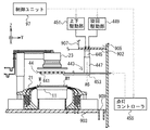
図1、図2および図3はこの発明に係る基板処理装置9の概略構成を示す図である。図1は基板処理装置9の正面図であり、図2は図1の基板処理装置9のB1−B1線に沿った矢視断面図である。また、図3は図1の基板処理装置9を矢印B2側からみた側面図である。この装置は半導体基板等の基板W(以下、単に「基板W」と記載する)に付着しているパーティクル等の汚染物質(以下「パーティクル等」と記載する)を除去するための洗浄処理に用いられる枚葉式の基板処理装置である。
First Embodiment
FIG. 1, FIG. 2 and FIG. 3 are diagrams showing a schematic configuration of a
なお、各図には方向関係を明確にするため、Z軸を鉛直方向とし、XY平面を水平面とする座標系を適宜付している。また、各座標系において、矢印の先端が向く方向を+(プラス)方向とし、逆の方向を−(マイナス)方向とする。 Note that, in order to clarify the directional relationship in each drawing, a coordinate system in which the Z axis is in the vertical direction and the XY plane is in the horizontal plane is appropriately attached. In each coordinate system, the direction in which the tip of the arrow points is the + (plus) direction, and the opposite direction is the − (minus) direction.
<1−1.基板処理装置の全体構成>
基板処理装置9は、基板Wを例えば25枚収容したFOUP(Front Open Unified Pod)949を載置するオープナー94と、オープナー94上のFOUP949から未処理の基板Wを取り出し、また処理完了後の基板WをFOUP949内に収納するインデクサユニット93と、インデクサユニット93とセンターロボット96との間で基板Wの受け渡しを行うシャトル95と、基板Wをセンターロボット96でその内部に収容して洗浄を行う処理ユニット91と、処理ユニット91に供給される液体や気体の配管、バルブ等を収容する流体ボックス92とで構成される。
<1-1. Overall configuration of substrate processing apparatus>
The
まず、これらの平面的な配置について図2を用いて説明する。基板処理装置9の一端(図2において左端)には複数の(本実施形態においては3台の)オープナー94が配置される。オープナー94の図2における右側(+Y側)に隣接してインデクサユニット93が配置される。インデクサユニット93のX方向における中央付近であって、インデクサユニットの図2における右側(+Y側)に隣接してシャトル95が配置され、シャトル95の図2における右側(+Y側)に、シャトル95と+Y方向に並ぶようにセンターロボット96が配置される。このように、インデクサユニット93と、シャトル95およびセンターロボット96は、直交する二本のラインの配置をなしている。
First, these planar arrangements will be described with reference to FIG. At one end (left end in FIG. 2) of the
+Y方向に並ぶように配置されたシャトル95とセンターロボット96の図2における上側(−X側)と下側(+X側)には処理ユニット91と流体ボックス92が配置されている。すなわち、シャトル95とセンターロボット96の図2における上側(−X側)または下側(+X側)に、インデクサユニット93の図2における右側(+Y側)に隣接して、流体ボックス92、処理ユニット91、処理ユニット91、流体ボックス92の順に配置されている。
A
なお、インデクサユニット93の+X側(図2における下側)の側面には後述する制御ユニット97の操作部971が設置されている(図1参照)。
An
次に、オープナー94について説明する。オープナー94はその上部にFOUP949を載置する載置面941と、FOUP949の正面(図1および図2におけるFOUP949の右側(+Y側)の面)に対向して配置され、FOUP949の正面にある蓋部(図示省略)を開閉する開閉機構943(図3参照)を備える。
Next, the
基板処理装置9の外部から自動搬送車両等により搬入されたFOUP949は、オープナー94の載置面941上に載置され、開閉機構943により蓋部が解放される。これにより、後述するインデクサユニット93のインデクサロボット931が、FOUP949内の基板Wを搬出し、逆にFOUP949内に基板Wを搬入することが可能となる。
The
次に、インデクサユニット93について説明する。インデクサユニット93には、FOUP949から処理工程前の基板Wを一枚ずつ取り出すとともに、処理工程後の基板WをFOUP949に一枚ずつ収容し、更に基板Wをシャトル95と受け渡しする、Z軸方向に上下に配置された2組のハンド933を有するインデクサロボット931が備えられている。インデクサロボット931はX軸方向に水平移動自在であり、またZ軸方向に昇降移動自在であるとともに、Z軸周りに回転可能に構成されている。
Next, the
次に、シャトル95について説明する。シャトル95には、基板Wの図2における上側(−X側)および下側(+X側)の周縁部付近であって、インデクサロボット931のハンド933および後述するセンターロボット96のハンド961と干渉しない位置を保持する、Z軸方向に上下に配置された2組のハンド951と、2組のハンド951をそれぞれ独立してY軸方向に水平移動する水平移動機構(図示せず)とを備える。
Next, the
シャトル95はインデクサロボット931とセンターロボット96双方との間で基板Wを受け渡し可能に構成されている。すなわち、図示しない水平移動機構によりハンド951が図2における左側(−Y側)に移動した場合、インデクサロボット931のハンド933との間で基板Wの受け渡しが可能となり、また、ハンド951が図2における右側(+Y側)に移動した場合はセンターロボット96のハンド961との間で基板Wの受け渡しが可能となる。
The
次に、センターロボット96について説明する。センターロボット96には、基板Wを1枚ずつ保持し、シャトル95または処理ユニット91との間で基板Wの受け渡しを行う、Z軸方向に上下に配置された2組のハンド961と、鉛直方向(Z軸方向)に延設され、ハンド961の鉛直方向の移動の軸となる昇降軸963と、ハンド961を昇降移動させる昇降機構965と、ハンド961をZ軸周りに回転させる回転機構967を備える。センターロボット96はZ軸方向に昇降軸963に沿って昇降移動自在であるとともに、回転機構967によってハンドがZ軸周りに回転可能に構成されている。
Next, the
なお、処理ユニット91の後述する側壁であって、センターロボット96に対向する面には、センターロボット96のハンド961を伸ばして処理ユニット91内に基板Wを搬入し、または搬出するための開口が設けられている。また、センターロボット96が処理ユニット91と基板Wの受け渡しを行わない場合に上記開口を閉塞して処理ユニット91内部の雰囲気の清浄度を保持するためのシャッター911が設けられている。
In the side wall of the
なお、図1に示すように処理ユニット91と流体ボックス92は上下2段に積み上げる構成とされている。したがって、本実施形態における基板処理装置9には処理ユニット91および流体ボックス92はそれぞれ8台ずつ備えられている。
As shown in FIG. 1, the
次に、インデクサロボット931、シャトル95およびセンターロボット96による基板Wの搬送の手順について説明する。基板処理装置9の外部から自動搬送車両等により搬入されたFOUP949は、オープナー94の載置面941上に載置され、開閉機構943により蓋部が解放される。インデクサロボット931はFOUP949の所定の位置から下側のハンド933により基板Wを1枚取り出す。その後、インデクサロボット931はシャトル95の前(図2におけるインデクサユニット93のX軸方向中央付近)に移動する。同時にシャトル95は下側のハンド951をインデクサユニット93の側(図2における左側(−Y側))へ移動する。
Next, the procedure of transfer of the substrate W by the
シャトル95の前に移動したインデクサロボット931は下側のハンド933に保持した基板Wをシャトル95の下側のハンド951に移載する。その後、シャトル95は下側のハンド951をセンターロボット96の側(図2における右側(+Y側))に移動する。また、センターロボット96がシャトル95にハンド961を向ける位置に移動する。
The
その後、センターロボット96が下側のハンド961により、シャトル95の下側のハンド951に保持された基板Wを取り出し、8つある処理ユニット91のいずれかのシャッター911へハンド961を向けるように移動する。その後、シャッター911が開放され、センターロボット96が下側のハンド961を伸ばして処理ユニット91内に基板Wを搬入し、処理ユニット91内での基板Wの洗浄処理が開始される。
Thereafter, the
処理ユニット91内で処理が完了した基板Wは、センターロボット96の上側のハンド961で搬出され、その後は上記未処理の基板Wを搬送する場合とは逆にセンターロボット96の上側のハンド961、シャトル95の上側のハンド951、インデクサロボット931の上側のハンド933の順に移載され、最終的にFOUP949の所定の位置に収容される。
The substrate W processed in the
<1−2.処理ユニット>
次に、処理ユニット91の構成について図4を用いて説明する。図4は処理ユニット91の構成を示す模式図である。ここで、本実施形態における8つの処理ユニット91はそれぞれ同じ構成であるため、図2における矢印B3の示す処理ユニット91(図1において左下側の処理ユニット91)を代表として以下説明する。
<1-2. Processing unit>
Next, the configuration of the
処理ユニット91は、表面にパターンが形成された基板Wを略水平に保持し、回転する基板保持部11と、基板保持部11をその内側に収容し、基板保持部11および基板Wからの飛散物等を受け止めて排気・排液する排液捕集部21と、基板保持部11に保持された基板表面Wfに対向して配置され、基板表面Wfの上方の空間を外気から遮断する雰囲気遮断部23とを備える。
The
また、処理ユニット91は、基板表面Wfに洗浄液を供給する洗浄部41と、基板表面Wfに向けてリンス液を供給するリンス部51と、基板表面Wfに乾燥補助液を供給する乾燥補助液供給部31と、基板表面Wfに乾燥気体を供給する乾燥気体供給部55と、後述する基板処理プログラムに基づいて基板処理装置9の各部の動作を制御する制御ユニット97とを備える。
The
洗浄液としては、水酸化アンモニウム、過酸化水素水および水の混合液(以下「SC−1」と記載する)、塩酸、過酸化水素水および水の混合液(以下「SC−2」と記載する)、希弗酸(以下「DHF」と記載する)、または硫酸、過酸化水素水および水の混合液(以下「SPM」と記載する)などが挙げられる。なお、本実施形態では、洗浄液としてSC−1を用いる。 As the cleaning solution, a mixture of ammonium hydroxide, hydrogen peroxide and water (hereinafter referred to as "SC-1"), a mixture of hydrochloric acid, hydrogen peroxide and water (hereinafter referred to as "SC-2") And dilute hydrofluoric acid (hereinafter referred to as “DHF”), or a mixed solution of sulfuric acid, hydrogen peroxide solution and water (hereinafter referred to as “SPM”), and the like. In the present embodiment, SC-1 is used as the cleaning liquid.
リンス液としては、脱イオン水(De Ionized Water:以下「DIW」と記載する)、イソプロピルアルコール(Iso Propyl Alcohol:以下「IPA」と記載する)などが挙げられる。なお、本実施形態ではリンス液としてDIWを用いる。 Examples of the rinse solution include deionized water (hereinafter referred to as "DIW"), isopropyl alcohol (hereinafter referred to as "IPA"), and the like. In the present embodiment, DIW is used as the rinse solution.
本実施形態では、乾燥補助液には、乾燥補助物質を溶媒に溶解させた、乾燥補助物質の溶液を用いる。 In the present embodiment, a solution of the dry auxiliary substance in which the dry auxiliary substance is dissolved in a solvent is used as the dry auxiliary liquid.
乾燥補助物質としては、炭酸水素アンモニウム(化学式:NH4HCO3。熱分解温度:摂氏58度。熱分解した際の生成物:水蒸気、二酸化炭素およびアンモニア。DIWに対して可溶性をもつ)、または過塩素酸アンモニウム(化学式:NH4ClO4。熱分解温度:摂氏150度程度。熱分解した際の生成物:塩素、水蒸気、窒素および酸素。DIWに対して可溶性をもつ)などが挙げられ、熱により気体の生成物に分解する物質が用いられる。 As a drying auxiliary substance, ammonium hydrogen carbonate (Chemical formula: NH 4 HCO 3. Thermal decomposition temperature: 58 ° C. Products upon thermal decomposition: water vapor, carbon dioxide and ammonia, soluble in DIW), or Ammonium perchlorate (chemical formula: NH 4 ClO 4 ; thermal decomposition temperature: about 150 ° C. products of thermal decomposition: chlorine, water vapor, nitrogen and oxygen, soluble in DIW), etc. A substance that decomposes into a gaseous product by heat is used.
また、乾燥補助物質の溶媒としては、DIWやIPAが挙げられ、乾燥補助物質が可溶な溶媒が選択される。なお、本実施形態では、乾燥補助液として、炭酸水素アンモニウムをDIWに溶解させた、炭酸水素アンモニウム水溶液を用いる。 Moreover, DIW and IPA are mentioned as a solvent of a drying auxiliary substance, and the solvent in which a drying auxiliary substance is soluble is selected. In the present embodiment, an aqueous solution of ammonium hydrogen carbonate in which ammonium hydrogen carbonate is dissolved in DIW is used as the drying auxiliary liquid.
また、本発明において、乾燥補助物質は、熱分解温度が常温以上であり、摂氏200度以下である物質を用いることが好ましい。熱分解温度が常温以上である乾燥補助物質を選ぶことにより、常温において熱分解を生じることなく基板表面Wfに乾燥補助液を供給することができる。また、熱分解温度が摂氏200度以下である物質を選ぶことにより、後述する加熱工程において、処理ユニット91を摂氏200度より高い温度にしなくても、熱分解を生じさせることができるため、処理ユニット91を構成する部材に耐熱性の高い部材を用いる必要がなく、装置の製造コストを削減することができる。
Further, in the present invention, as the drying auxiliary substance, it is preferable to use a substance having a thermal decomposition temperature of not less than ordinary temperature and not more than 200 degrees Celsius. By selecting the drying auxiliary substance whose thermal decomposition temperature is equal to or higher than normal temperature, the dry auxiliary liquid can be supplied to the substrate surface Wf without causing thermal decomposition at normal temperature. In addition, by selecting a substance having a thermal decomposition temperature of 200 ° C. or lower, thermal decomposition can be generated without setting the temperature of the
乾燥気体は、気体中に含まれる水蒸気の露点が、基板W近傍の雰囲気の温度よりも低い(すなわち、気体中に含まれる水蒸気の分圧が、基板W近傍の雰囲気における水の蒸気圧よりも低い)気体である。乾燥気体としては、窒素ガス、アルゴンガス、ヘリウムガス、または清浄乾燥空気(Clean Dry Air,窒素ガスと酸素ガスの分圧比が約80%:約20%の気体)が挙げられる。なお、本実施形態では、窒素ガスを乾燥空気として用いる。 In the dry gas, the dew point of water vapor contained in the gas is lower than the temperature of the atmosphere near the substrate W (that is, the partial pressure of water vapor contained in the gas is higher than the vapor pressure of water in the atmosphere near the substrate W Low) gas. The dry gas may, for example, be nitrogen gas, argon gas, helium gas or clean dry air (a gas having a partial pressure ratio of about 80% to about 20% of nitrogen gas and oxygen gas). In the present embodiment, nitrogen gas is used as dry air.
次に、処理ユニット91について説明する。処理ユニット91は、中空の略角柱形状を有する側壁901と、側壁901に略水平に固設され、処理ユニット91内の空間を仕切る上側ベース部材902および下側ベース部材903と、側壁901の内部であって上側ベース部材902の上方である上側空間905と、側壁901の内部であって、上側ベース部材902の下方であり、かつ下側ベース部材903の上方である処理空間904と、側壁901の内部であって下側ベース部材903の下方である下側空間906とを備える。なお、本実施形態において側壁901は略角柱形状としたが、側壁の形状はそれに限定されず、略円柱形状やその他の形状としても良い。
Next, the
なお、前述のとおり側壁901の内センターロボット96に対向する側には、センターロボットが処理ユニット91内に基板Wを搬入し、または搬出可能な開口と、その開口を閉塞して処理ユニット91内部の雰囲気の清浄度を保持するためのシャッター911が設けられている。
As described above, on the side opposite to the
上側ベース部材902は側壁901の上方(図4における上側)に略水平に固設され、処理ユニット91の内部の空間である上側空間905と処理空間904との間を仕切っている。上側ベース部材902の中央付近には、上側ベース部材902の下面から、処理ユニット91の上端に連通する雰囲気導入路907が設けられている。また、雰囲気導入路907の上端付近には、処理空間904へ清浄な雰囲気を供給するファンフィルタユニット908が設けられている。上側空間905内の雰囲気導入路907に設置されたファンフィルタユニット908は、処理ユニット91上方から雰囲気を取り込み、内蔵したHEPAフィルタ等により雰囲気中の微粒子等を捕集した上で、下方である処理空間904内へ清浄化された雰囲気を供給する。
The
下側ベース部材903は側壁901の中程(図4における下側)に略水平に固設され、処理ユニット91の内部の空間である処理空間904と下側空間906との間を仕切っている。下側ベース部材903には複数の排気口909が設けられており、各排気口909は図示しない排気系統に接続され、処理空間904内の雰囲気を外部に排出している。
The
ここで、処理空間904内は清浄な雰囲気が保たれており、基板Wの洗浄等が行われる空間である。また、上側空間905および下側空間906は処理空間904内に設置される各部材を駆動するための駆動源等が配設される空間である。
Here, the inside of the
ファンフィルタユニット908を通して処理空間904内に供給された雰囲気は、処理空間904の上方から下方へ向かう流れとなり、最終的に排気口909から処理空間904の外に排出される。これにより、後述する基板Wを処理する各工程において発生する微細な液体の微粒子等を、処理空間904の中を上から下に向かって流れる気流により下向きに移動させて排気口909から排出する。よって、これら微粒子が基板Wや処理空間904内の各部材に付着することを防止できる。
The atmosphere supplied into the
次に、基板保持部11、排液捕集部21および雰囲気遮断部23の構成について図5を用いて説明する。図5は基板保持部11、排液捕集部21および雰囲気遮断部23の構成を示す模式図である。
Next, configurations of the
まず、基板保持部11について説明する。基板保持部11のベースユニット111は下側ベース部材903の上に固設されており、ベースユニット111の上方に、中心部に開口を有する円板状のスピンベース113が回転可能に略水平に支持されている。スピンベース113の下面中心には中心軸117の上端がネジなどの締結部品によって固定されている。また、スピンベース113の周縁付近には、基板Wの周縁部を把持するための複数個の基板保持部材115が立設されている。基板保持部材115は、円形の基板Wを確実に保持するために3個以上設けてあればよく、スピンベース113の周縁に沿って等角度間隔で配置されている。各基板保持部材115のそれぞれは、基板Wの周縁部を下方から支持する支持ピンと、基板支持部に支持された基板Wの外周端面を押圧して基板Wを保持する保持ピンとを備えている。
First, the
各基板保持部材115は公知のリンク機構や褶動部材等を介して基板保持部材駆動機構119内のエアシリンダに連結されている。なお、基板保持部材駆動機構119はスピンベース113の下側であってベースユニット111の内部に設置されている。また、基板保持部材駆動機構119は制御ユニット97と電気的に接続されている。そして、制御ユニット97が基板保持部11へ動作指令を行い、基板保持部材駆動機構119のエアシリンダを伸縮する。これにより、各基板保持部材115を、その保持ピンが基板Wの外周端面を押圧する「閉状態」と、その保持ピンが基板Wの外周端面から離れる「開状態」との間を切り替え可能としている。なお、基板保持部材115の駆動源としてエアシリンダ以外に、モーターやソレノイド等の公知の駆動源を用いることも可能である。
Each
そして、スピンベース113に対して基板Wが受渡しされる際には、各基板保持部材115を開状態とし、基板Wに対して洗浄処理等を行う際には、各基板保持部材115を閉状態とする。各基板保持部材115を閉状態とすると、各基板保持部材115が基板Wの周縁部を把持し、基板Wをスピンベース113から所定間隔を隔てて略水平姿勢に保持する。これにより、基板表面Wfを上方に向け、基板裏面Wbを下方に向けた状態で保持される。
When the substrate W is delivered to the
また、基板保持部11の中心軸117には、モーターを含む基板回転機構121の回転軸が連結されている。なお、基板回転機構121は下側ベース部材903の上であってベースユニット111の内部に設置される。また、基板回転機構121は制御ユニット97と電気的に接続されている。そして、制御ユニット97が基板保持部11へ動作指令を行い、基板回転機構121を駆動する。これにより、中心軸117に固定されたスピンベース113が回転中心軸A1を中心に回転する。
Further, the rotation axis of the substrate rotation mechanism 121 including a motor is connected to the central axis 117 of the
次に、排液捕集部21について説明する。基板保持部11の周囲であって下側ベース部材903の上側に略円環状のカップ210が、基板保持部11に保持されている基板Wの周囲を包囲するように設けられている。カップ210は基板保持部11および基板Wから飛散する液体などを捕集することが可能なように回転中心軸A1に対して略回転対称な形状を有している。なお、各図中において、カップ210については説明のため断面形状を示している。
Next, the
カップ210は互いに独立して昇降可能な内構成部材211、中構成部材213および外構成部材215で構成される。図5に示すとおり、内構成部材211の上に中構成部材213および外構成部材215が重ねられた構造を有する。内構成部材211、中構成部材213および外構成部材215は、下側空間906に設けられた、モーターおよびボールネジ等の公知の駆動機構で構成されたガード昇降機構217にそれぞれ接続されている。また、ガード昇降機構217は制御ユニット97と電気的に接続されている。そして、制御ユニット97が排液捕集部21へ動作指令を行い、ガード昇降機構217を駆動する。これにより、内構成部材211、中構成部材213および外構成部材215がそれぞれ独立に、又は複数の部材が同期して回転中心軸A1に沿って上下方向に移動する。
The cup 210 is composed of an
内構成部材211には、内構成部材211、中構成部材213および外構成部材215それぞれで捕集された液体をそれぞれ別の経路で排液処理系へ導くための収集溝が3つ設けられている。それぞれの収集溝は回転中心軸A1を中心とする略同心円状に設けられ、各収集溝には図示しない排液処理系へと接続する配管がそれぞれ管路接続されている。
The
カップ210は内構成部材211、中構成部材213および外構成部材215のそれぞれの上下方向の位置を組合せて使用する。すなわち、内構成部材211、中構成部材213および外構成部材215の全てが下位置にあるホームポジション、内構成部材211および中構成部材213が下位置であって外構成部材215のみ上位置にある外捕集位置、内構成部材211が下位置であって中構成部材213および外構成部材215が上位置に有る中捕集位置、および内構成部材211、中構成部材213および外構成部材215の全てが上位置にある内捕集位置である。
The cup 210 is used by combining the positions of the
ホームポジションはセンターロボット96が基板Wを処理ユニット91内に搬入出する場合などにおいて取られる位置である。外捕集位置は外構成部材215で受け止めた液体を捕集して外側の収集溝に導く位置であり、中捕集位置は中構成部材213で受け止めた液体を中間の収集溝に導く位置であり、また、内捕集位置は内構成部材211で受け止めた液体を内側の収集溝に導く位置である。
The home position is a position that is taken when the
このような構成の排液捕集部21を用いることにより、処理に使用される液体に応じて内構成部材211、中構成部材213および外構成部材215のそれぞれの位置を変更して分別捕集することが可能となる。したがって、それぞれの液体を分別し、対応する排液処理系に排出することで、液体の再利用や混合することが危険な複数の液体を分別して処理することが可能となる。
By using the
次に、雰囲気遮断部23について説明する。雰囲気遮断部23の基板対向部材である遮断部材231は、中心部に開口を有する円板状に形成されている。遮断部材231の下面は、基板表面Wfと略平行に対向する基板対向面となっている。また、遮断部材231の直径は基板Wの直径と同等以上の大きさに形成されている。遮断部材231は、その内部が中空であって略円筒形状を有する支持軸233の下方に回転可能に略水平に支持される。
Next, the
支持軸233の上端部は遮断部材231を回転する遮断部材回転機構235の下面に固設される。遮断部材回転機構235は、中空モーター237および中空軸239で構成される。中空軸239の一端(図5における上端)は中空モーター237の回転軸に連結されており、他端(図5における下端)は支持軸233の中を通して遮断部材231の上面に連結されている。
The upper end portion of the
また、遮断部材回転機構235は制御ユニット97と電気的に接続されている。そして、制御ユニット97が雰囲気遮断部23へ動作指令を行い、遮断部材回転機構235を駆動する。これにより、遮断部材231を支持軸233の中心を通る回転中心軸A5周りに回転する。遮断部材回転機構235は、基板保持部11に保持された基板Wの回転に応じて基板Wと同じ回転方向でかつ略同じ回転速度で遮断部材231を回転させるように構成されている。なお、スピンベース113と遮断部材231は、回転中心軸A1とA5が略一致するよう配設されている。したがって、スピンベース113と遮断部材231略同じ回転中心軸の周りに回転する。
Further, the blocking
なお、遮断部材回転機構235の上面から遮断部材231の中心部の開口にいたるまで、後述する配管515,555が挿通可能なように、中空モーター237および中空軸239の内部空間を含む連通した中空部が形成されている。
Note that the
遮断部材回転機構235の一側面(図5における左側面)にはアーム241の一端が接続され、アーム241の他端は上下軸243の図5における上端付近に接続されている。上下軸243は排液捕集部21のカップ210の周方向外側であって、下側ベース部材903の上に固設された円筒形状のベース部材245に昇降可能に取り付けられる。上下軸243には、ベース部材245の中を通して、モーターおよびボールネジ等の公知の駆動機構で構成された遮断部材昇降機構247が接続されている。
One end of the
なお、遮断部材昇降機構247は下側空間906に設けられている。また、遮断部材昇降機構247は制御ユニット97と電気的に接続されている。そして、制御ユニット97が雰囲気遮断部23へ動作指令を行い、遮断部材昇降機構247を駆動する。これにより、遮断部材231をスピンベース113に近接し、逆に離間する。
The blocking
すなわち、制御ユニット97は、遮断部材昇降機構247の動作を制御して処理ユニット91に対して基板Wを搬入出させる際や、基板Wに対して、後述する洗浄工程、および乾燥補助液供給工程を行う際には、遮断部材231を基板保持部11の上方の離間位置に上昇させる。一方、基板Wに対して後述するリンス工程、析出工程、加熱工程および冷却工程を行う際には、遮断部材231を基板保持部11に保持された基板表面Wfのごく近傍に設定された対向位置まで下降させる。
That is, when the
次に、洗浄部41の構成について図6を用いて説明する。図6は洗浄部41の構成を示す模式図である。基板表面Wfに洗浄液を供給するノズル411は、上側ベース部材902の下面に設置されたノズル駆動機構413に昇降および旋回可能に支持されている。ノズル駆動機構413のベース部材415は、上側ベース部材902の下面であって雰囲気導入路907の外側に下方に伸びるように固設されている。
Next, the configuration of the
ベース部材415の下方には、旋回上下軸417が上下および回転自在に保持されている。なお、ベース部材415は旋回上下軸417と、後述する上下駆動部421および旋回駆動部419を接続するために中空の略円筒形状に構成される。旋回上下軸417の下面にはアーム423の一端が結合されており、アーム423の他端にノズル411が取り付けられている。
Below the
旋回上下軸417はベース部材415の中を通して、モーターおよびボールネジ等の公知の駆動機構で構成された上下駆動部421および、モーターおよびギア等の公知の駆動機構で構成された旋回駆動部419に接続されている。また、上下駆動部421および旋回駆動部419は制御ユニット97と電気的に接続されている。なお、上下駆動部421および旋回駆動部419は上側空間905に配設される。
The pivoting upper and lower shafts 417 are connected through the inside of the
制御ユニット97がノズル駆動機構413へ動作指令を行い、上下駆動部421を駆動する。これにより、旋回上下軸417が上下に移動し、アーム423に取り付けられているノズル411を上下に移動する。また、制御ユニット97がノズル駆動機構413へ動作指令を行い、旋回駆動部419を駆動する。これにより、旋回上下軸417が回転中心軸A4を中心に回転し、アーム423を旋回することで、アーム423に取り付けられたノズル411を揺動する。
The
ノズル411は配管427を介して洗浄液供給ユニット425に、管路接続されている。配管427には開閉弁429が介挿されており、開閉弁429は常時閉成とされている。また、開閉弁429は制御ユニット97と電気的に接続されている。そして、制御ユニット97が洗浄部41へ動作指令を行い、開閉弁429を開成する。これにより、洗浄液が洗浄液供給ユニット425から配管427、およびノズル411を介して基板表面Wfに供給される。なお、洗浄液供給ユニット425は、基板処理装置9の内部に設けられていても、外部に設けられていてもよい。
The
この、洗浄液供給ユニット425、配管427、開閉弁429、ノズル411およびノズル駆動機構413が、洗浄部41を構成する。
The cleaning
次に、リンス部51および乾燥気体供給部55の構成について図7を用いて説明する。図7は、リンス部51および乾燥気体供給部55の構成を示す模式図である。リンス部51は基板表面Wfに向けてリンス液(DIW)を供給するものであり、乾燥気体供給部55は基板表面Wfに向けて乾燥気体(窒素ガス)を供給するものである。
Next, the configurations of the rinse
まず、リンス部51および乾燥気体供給部55の管路構成について説明する。上記の雰囲気遮断部23の遮断部材回転機構235の上面から、遮断部材231の中心部の開口まで連通する中空部の内部に外側供給管271が挿通されるとともに、当該外側供給管271に内側供給管273が挿通され、いわゆる二重管構造となっている。この外側供給管271および内側供給管273の下方端部は遮断部材231の開口に延設されており、内側供給管273の先端にノズル275が設けられている。
First, the pipe configuration of the rinse
次に、リンス部51について説明する。リンス部51はリンス液の供給源であるリンス液供給ユニット513から基板表面Wfにリンス液を供給する。図示しないDIWタンク、温度調整ユニットおよびポンプを有するリンス液供給ユニット513に配管515の一端が管路接続されている。配管515の他端は内側供給管273に管路接続されている。また、リンス液供給ユニット513のポンプは基板処理装置9が起動した時点から常時動作している。
Next, the rinse
配管515には開閉弁519が介挿されている。なお、開閉弁519は常時閉成されている。開閉弁519は制御ユニット97に電気的に接続されている。そして、制御ユニット97がリンス部51へ動作指令を行い、開閉弁519を開成する。これにより、リンス液がリンス液供給ユニット513から配管515、内側供給管273およびノズル275を介して基板表面Wfに供給される。
An on-off
この、リンス液供給ユニット513、配管515、開閉弁519、内側供給管273、およびノズル275がリンス部51を構成する。なお、リンス液供給ユニット513は、基板処理装置9の内部に設けられていても、外部に設けられていてもよい。
The rinse
次に、乾燥気体供給部55について説明する。乾燥気体供給部55は乾燥気体の供給源である乾燥気体供給ユニット553から基板表面Wfに乾燥気体を供給する。乾燥気体供給ユニット553には、配管555の一端が管路接続し、配管555の他端は外側供給管271に管路接続している。
Next, the dry gas supply unit 55 will be described. The dry gas supply unit 55 supplies dry gas to the substrate surface Wf from the dry
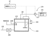
図8に、本実施形態における乾燥気体供給ユニット553の構成を示す。乾燥気体供給ユニット553は、乾燥気体として用いる窒素ガスを貯留する窒素ガスタンク556と、窒素ガスタンク556からの窒素ガスを圧送するポンプ557と、窒素ガスを加熱するガス加熱ユニット559と、ガス加熱ユニット559に供給される窒素ガスの流量を制御するマスフローコントローラ558とを有する。
The structure of the dry
ここで、ガス加熱ユニット559は、抵抗加熱ヒータなど、公知の加熱手段を用いることができる。窒素ガスタンク556には、常温の窒素ガスが貯留されている。なお、本実施形態では窒素ガスタンク556を設けるが、本発明の実施に関してはこれに限られず、乾燥気体供給ユニット553に窒素ガスタンク556を設けずに、工場ユーティリティー側から直接窒素ガスを供給する構成とすることも可能である。
Here, as the
ポンプ557、マスフローコントローラ558、およびガス加熱ユニット559は制御ユニット97と電気的に接続されている。なお、ポンプ557は基板処理装置9が起動した時点から常時動作している。
The
制御ユニット97が乾燥気体供給部55へ動作指令を行うと、マスフローコントローラ558が所定流量となるように開放される。これにより、窒素ガスタンク556内の常温の窒素ガスが、ポンプ557によりガス加熱ユニット559へ圧送され、ガス加熱ユニット559を介した後、配管555、および外側供給管271の内面と内側供給管273の外面との間の空間を通って、基板表面Wfに供給される。
When the
加熱した窒素ガスを基板表面Wfへ供給する際には、制御ユニット97が乾燥気体供給部55へ動作指令を行い、ガス加熱ユニット559による窒素ガスの加熱が行われる。
When supplying the heated nitrogen gas to the substrate surface Wf, the
この、乾燥気体供給ユニット553、配管555、窒素ガスタンク556、ポンプ557、マスフローコントローラ558、ガス加熱ユニット559、および外側供給管271の内面と内側供給管273の外面が、乾燥気体供給部55を構成する。なお、乾燥気体供給ユニット553は、基板処理装置9の内部に設けられていても、外部に設けられていてもよい。
The dry
次に、乾燥補助液供給部31の構成について図9を用いて説明する。図9は乾燥補助液供給部31の構成を示す模式図である。基板Wに乾燥補助液を供給するノズル311は、上側ベース部材902の下面に設置されたノズル駆動機構313に昇降および旋回可能に支持されている。ノズル駆動機構313のベース部材315は、上側ベース部材902の下面であって雰囲気導入路907の外側に下方に伸びるように固設されている。
Next, the configuration of the drying auxiliary
ベース部材315の下方には、旋回上下軸317が上下および回転自在に保持されている。なお、ベース部材315は旋回上下軸317と、後述する上下駆動部321および旋回駆動部319を接続するために中空の略円筒形状に構成される。旋回上下軸317の下面にはアーム323の一端が結合されており、アーム323の他端にノズル311が取り付けられている。
Below the
旋回上下軸317はベース部材315の中を通して、モーターおよびボールネジ等の公知の駆動機構で構成された上下駆動部321および、モーターおよびギア等の公知の駆動機構で構成された旋回駆動部319に接続されている。また、上下駆動部321および旋回駆動部319は制御ユニット97と電気的に接続されている。なお、上下駆動部321および旋回駆動部319は上側空間905に配設される。
The pivoting upper and
制御ユニット97が乾燥補助液供給部31へ動作指令を行い、上下駆動部321を駆動する。これにより、旋回上下軸317が上下に移動し、アーム323に取り付けられているノズル311を上下に移動する。また、制御ユニット97が乾燥補助液供給部31へ動作指令を行い、旋回駆動部319を駆動する。これにより、旋回上下軸317が回転中心軸A2を中心に回転し、アーム323を旋回することで、アーム323に取り付けられたノズル311を揺動する。
The
ノズル311は配管335を介して、乾燥補助液供給ユニット333に管路接続されている。配管335には開閉弁337が介挿されており、開閉弁337は常時閉成とされている。また、開閉弁337は制御ユニット97と電気的に接続されている。そして、制御ユニット97が乾燥補助液供給部31へ動作指令を行い、開閉弁337を開成する。これにより、乾燥補助液が乾燥補助液供給ユニット333から配管335およびノズル311を介して基板表面Wfに供給される。なお、乾燥補助液供給ユニット333は、基板処理装置9の内部に設けられていても、外部に設けられていてもよい。
The
図10に本実施形態における乾燥補助液供給ユニット333の構成を示す。乾燥補助液供給ユニット333は、乾燥補助液として用いる炭酸水素アンモニウム水溶液を貯留する炭酸水素アンモニウム水溶液タンク339、炭酸水素アンモニウム水溶液タンク339内の炭酸水素アンモニウム水溶液を撹拌する撹拌部349、および炭酸水素アンモニウム水溶液タンク339を加圧して炭酸水素アンモニウム水溶液を送出する加圧部345で構成される。
The structure of the drying auxiliary
炭酸水素アンモニウム水溶液タンク339内には、DIWに炭酸水素アンモニウムを溶解させた炭酸水素アンモニウム水溶液が貯留されている。本実施形態では、炭酸水素アンモニウムの濃度が1%である炭酸水素アンモニウム水溶液を炭酸水素アンモニウム水溶液タンク339に貯留する。
In the ammonium hydrogencarbonate
撹拌部349は、炭酸水素アンモニウム水溶液タンク339内の炭酸水素アンモニウム水溶液を撹拌する回転部351と、回転部351の回転を制御する撹拌制御部353を備えている。撹拌制御部353は制御ユニット97と電気的に接続している。回転部351は、回転軸の先端(図10における回転部351の下端)にプロペラ状の攪拌翼を備えており、制御ユニット97が撹拌制御部353へ動作指令を行い、回転部351が回転することで、攪拌翼が炭酸水素アンモニウム水溶液を撹拌し、炭酸水素アンモニウム水溶液において、DIWに溶解する炭酸水素アンモニウムの濃度を均一化する。
The stirring
また、炭酸水素アンモニウム水溶液タンク339内の炭酸水素アンモニウム水溶液の濃度を均一にする方法としては、上記した方法に限られず、別途循環用のポンプを設けて炭酸水素アンモニウム水溶液を循環する方法等、公知の方法を用いることができる。
Further, the method of making the concentration of the ammonium hydrogencarbonate aqueous solution in the ammonium hydrogencarbonate
加圧部345は、炭酸水素アンモニウム水溶液タンク339を加圧する気体の供給源である窒素ガスタンク341、窒素ガスを加圧するポンプ343および配管347で構成される。窒素ガスタンク341は配管347により炭酸水素アンモニウム水溶液タンク339と管路接続されており、また配管347にはポンプ343が介挿されている。
The pressurizing
炭酸水素アンモニウム水溶液タンク339内には気圧センサ(図示省略)が設けられ、制御ユニット97と電気的に接続されている。制御ユニット97は、気圧センサが検出した値に基づいてポンプ343の動作を制御することにより、炭酸水素アンモニウム水溶液タンク339内の気圧を大気圧より高い所定の気圧に維持する。これにより、制御ユニット97が乾燥補助液供給部31へ動作指令を行い、開閉弁337を開成すると、加圧されている炭酸水素アンモニウム水溶液タンク339内から炭酸水素アンモニウム水溶液が押し出され、配管335を介してノズル311から吐出される。なお、炭酸水素アンモニウム水溶液タンク339は、上記のとおり窒素ガスによる気圧を用いて炭酸水素アンモニウム水溶液を供給するため、気密に構成されることが好ましい。
An atmospheric pressure sensor (not shown) is provided in the ammonium hydrogencarbonate
次に、制御ユニット97の構成について図11を用いて説明する。図11は制御ユニット97の構成を示す模式図である。制御ユニット97は、基板処理装置9の各部と電気的に接続しており(図5から図10まで参照)、各部の動作を制御する。制御ユニット97は、演算処理部973やメモリ975を有するコンピュータにより構成されている。演算処理部973としては、各種演算処理を行うCPUを用いる。また、メモリ975は、基本プログラムを記憶する読み出し専用のメモリであるROM、各種情報を記憶する読み書き自在のメモリであるRAMおよび制御用ソフトウェアやデータなどを記憶しておく磁気ディスクを備える。磁気ディスクには、基板Wに応じた基板処理条件が、基板処理プログラム977(レシピとも呼ばれる)として予め格納されおり、CPUがその内容をRAMに読み出し、RAMに読み出された基板処理プログラムの内容に従ってCPUが基板処理装置9の各部を制御する。なお、制御ユニット97には基板処理プログラム977の作成・変更や、複数の基板処理プログラム977の中から所望のものを選択するために用いる操作部971(図1参照)が接続されている。
Next, the configuration of the
<1−3.基板処理の工程>
次に、上記のように構成された基板処理装置9における基板処理動作について説明する。ここで、基板表面Wfには、凹凸のパターンが前工程により形成されている。パターンは、凸部および凹部を備えている。凸部は、100〜200nmの範囲の高さであり、10〜20nmの範囲の幅である。また、隣接する凸部間の距離(凹部の幅)は、10〜20nmの範囲である。
<1-3. Process of substrate processing>
Next, the substrate processing operation in the
以下、図4から図11までを適宜参照しながら、図12を用いて基板処理の工程を説明する。図12は本実施形態における基板処理装置9の全体の動作を示すフローチャートである。なお、以下の説明において特に断らない限り、雰囲気遮断部23は、遮断部材231が対向位置にある場合、基板保持部11の基板回転機構121がスピンベース113を回転する方向に略同じ回転数で遮断部材231を回転するものとする。
Hereinafter, the process of the substrate processing will be described using FIG. 12 with reference to FIG. 4 to FIG. 11 as appropriate. FIG. 12 is a flowchart showing the overall operation of the
まず、所定の基板Wに応じた基板処理プログラムが操作部971で選択され、実行指示される。その後、基板Wを処理ユニット91に搬入する準備として、制御ユニット97が動作指令を行い以下の動作をする。
First, a substrate processing program corresponding to a predetermined substrate W is selected by the
すなわち、雰囲気遮断部23が遮断部材231の回転を停止し、基板保持部11がスピンベース113の回転を停止する。雰囲気遮断部23が遮断部材231を離間位置へ移動すると共に、基板保持部11がスピンベース113を基板Wの受け渡しに適した位置へ位置決めする。また、排液捕集部21がカップ210をホームポジションに位置決めする。スピンベース113が基板Wの受け渡しに適した位置に位置決めされた後、基板保持部11が基板保持部材115を開状態とする。
That is, the
また、乾燥補助液供給部31がノズル311を、洗浄部41がノズル411をそれぞれ退避位置(各ノズルがカップ210の周方向外側に外れている位置)へ移動する。更に、開閉弁337、429、および519を閉成する。また、マスフローコントローラ558を流量0(ゼロ)に設定する。
Further, the drying auxiliary
基板Wを処理ユニット91に搬入する準備が完了した後、未処理の基板Wを処理ユニット91へ搬入する基板搬入工程(ステップS101)を行う。すなわち、インデクサロボット931がオープナー94上のFOUP949の所定の位置にある基板Wを下側のハンド933で取り出し、シャトル95の下側のハンド951に載置する。その後、シャトル95の下側のハンド951をセンターロボット96の側に移動し、センターロボット96がシャトル95の下側のハンド951上の基板Wを、下側のハンド961で取り上げる。
After the preparation for loading the substrate W into the
その後、処理ユニット91のシャッター911が開かれ、センターロボット96が下側のハンド961を処理ユニット91の中に伸ばし、基板Wを基板保持部11の基板保持部材115の支持ピンの上に載置する。基板Wの処理ユニット91への搬入が終了すると、センターロボット96が下側のハンド961を縮めて処理ユニット91の外に出る。その後、シャッター911が閉じる。
Thereafter, the
未処理の基板Wが処理ユニット91内に搬入され、基板保持部材115の支持ピンの上に載置されると、制御ユニット97が基板保持部11へ動作指令を行い、基板保持部材115を閉状態とする。
When an unprocessed substrate W is carried into the
未処理の基板Wが基板保持部11に保持された後、基板表面Wfに対して、洗浄液であるSC−1を供給する洗浄工程(ステップS102)を行う。まず、制御ユニット97が基板保持部11へ動作指令を行い、スピンベース113の回転を開始し、洗浄工程の間、回転を維持する。また、制御ユニット97が排液捕集部21へ動作指令を行い、カップ210を中捕集位置に位置決めする。なお、雰囲気遮断部23の遮断部材231は離間位置を維持する。
After the unprocessed substrate W is held by the
ここで、基板Wの回転速度は、基板表面Wfに供給された洗浄液が基板表面Wfの全面に拡散可能となるように、100〜1000rpmとすることが好ましい。本実施形態では、洗浄工程における基板Wの回転速度を500rpmとして説明する。 Here, the rotational speed of the substrate W is preferably 100 to 1000 rpm so that the cleaning liquid supplied to the substrate surface Wf can diffuse to the entire surface of the substrate surface Wf. In the present embodiment, the rotational speed of the substrate W in the cleaning process will be described as 500 rpm.
次に、制御ユニット97が洗浄部41へ動作指令を行い、ノズル411を基板表面Wfの中心付近上空へ位置決めする。ノズル411の位置決めが完了した後、制御ユニット97が洗浄部41へ動作指令を行い、開閉弁429を開成する。これにより、SC−1を、洗浄液供給ユニット425から配管427およびノズル411を介して基板表面Wfの中心付近に供給する。
Next, the
基板表面Wfの中心付近に供給されたSC−1は、基板Wが回転することにより生ずる遠心力により、基板Wの中心から基板Wの周縁部に向かって流動し、基板表面Wf全面に拡散する。このSC−1の流動に伴って、基板表面Wfに形成されたパターンの凹部にまでSC−1が侵入し、基板表面Wfに付着したパーティクル等を除去する。 The SC-1 supplied near the center of the substrate surface Wf flows from the center of the substrate W toward the peripheral portion of the substrate W by the centrifugal force generated by the rotation of the substrate W and diffuses over the entire surface of the substrate Wf . Along with the flow of SC-1, SC-1 intrudes into the concave portion of the pattern formed on the substrate surface Wf, and removes particles and the like attached to the substrate surface Wf.
基板表面Wfの全面にSC−1が拡散した後、制御ユニット97が洗浄部41へ動作指令を行い、開閉弁429を閉成する。また、制御ユニット97が洗浄部41へ動作指令を行い、ノズル411を退避位置(ノズル411がカップ210の周方向外側に外れている位置)へ位置決めする。
After SC-1 diffuses over the entire surface of the substrate surface Wf, the
次に、SC−1が付着している基板表面Wfにリンス液としてDIWを供給するリンス工程(ステップS103)を行う。まず、制御ユニット97が排液捕集部21へ動作指令を行い、カップ210を外捕集位置に位置決めする。また、制御ユニット97が雰囲気遮断部23へ動作指示を行い、遮断部材231を対向位置へ移動する。
Next, a rinse step (step S103) of supplying DIW as a rinse solution to the substrate surface Wf to which SC-1 is attached is performed. First, the
リンス工程における基板Wの回転速度は、基板表面Wfに供給されたリンス液としてのDIWが基板表面Wfの全面に拡散可能であり、かつ基板表面Wfを拡散する流れにより、基板表面Wfに付着した洗浄液を排除可能なように100〜1000rpmとすることが好ましい。以下では、リンス工程における基板Wの回転速度を800rpmとして説明する。 The rotational speed of the substrate W in the rinse step was such that DIW as a rinse solution supplied to the substrate surface Wf was able to diffuse over the entire surface of the substrate surface Wf, and was attached to the substrate surface Wf by the flow of diffusing the substrate surface Wf. It is preferable to set it as 100-1000 rpm so that a washing | cleaning liquid can be excluded. Hereinafter, the rotational speed of the substrate W in the rinse step will be described as 800 rpm.
遮断部材231を対向位置に位置決めした後、制御ユニット97がリンス部51へ動作指示を行い、開閉弁519を開成する。
After positioning the blocking
これにより、DIWをリンス液供給ユニット513から、配管515、内側供給管273およびノズル275を介して基板表面Wfへ供給する。基板表面Wfの中心付近に供給されたDIWは、基板Wの回転による遠心力により、基板周縁方向に流動し、最終的には基板周縁部から基板W外へ飛散し、排液捕集部21に捕集されて排液される。
Thereby, DIW is supplied from the rinse
なお、リンス液として用いられるDIWは、洗浄工程において基板Wに付着した洗浄液だけでなく、雰囲気の中に浮遊していたパーティクル等が基板Wに付着したものなどを除去する役割も果たす。 The DIW used as the rinse solution plays a role of removing not only the cleaning liquid adhering to the substrate W in the cleaning step, but also particles etc. suspended in the atmosphere adhering to the substrate W.
リンス工程終了後、制御ユニット97がリンス部51へ動作指令を行い、開閉弁519を閉成する。
After the end of the rinse process, the
次に、リンス液が付着している基板表面Wfに乾燥補助液として炭酸水素アンモニウム水溶液を供給する乾燥補助液供給工程(ステップS104)を行う。まず、制御ユニット97が排液捕集部21へ動作指令を行い、カップ210を内捕集位置に位置決めする。また、制御ユニット97が雰囲気遮断部23へ動作指示を行い、遮断部材231を離間位置へ移動する。
Next, a drying auxiliary liquid supplying step (step S104) of supplying an aqueous solution of ammonium hydrogen carbonate as a drying auxiliary liquid to the substrate surface Wf to which the rinse liquid adheres is performed. First, the
次に、制御ユニット97が乾燥補助液供給部31へ動作指令を行い、ノズル311を基板表面Wfの中心付近上空へ位置決めする。ノズル311の位置決めが完了した後、制御ユニット97が乾燥補助液供給部31へ動作指令を行い、開閉弁337を開成する。これにより、炭酸水素アンモニウム水溶液を、乾燥補助液供給ユニット333から配管335およびノズル311を介して基板表面Wfの中心付近に供給する。
Next, the
基板表面Wfの中心付近に供給された炭酸水素アンモニウム水溶液は、基板Wが回転することにより生ずる遠心力により、基板Wの中心から基板Wの周縁部に向かって流動し、基板表面Wf全面に拡散する。この炭酸水素アンモニウム水溶液の流動に伴って、基板表面Wfに形成されたパターンの凹部にまで炭酸水素アンモニウム水溶液が侵入し、炭酸水素アンモニウム水溶液を供給する前に基板表面Wfに付着していたリンス液としてのDIWを除去する。 The ammonium hydrogencarbonate aqueous solution supplied near the center of the substrate surface Wf flows from the center of the substrate W toward the peripheral portion of the substrate W by the centrifugal force generated by the rotation of the substrate W, and diffuses over the entire substrate surface Wf Do. With the flow of the ammonium hydrogencarbonate aqueous solution, the ammonium hydrogencarbonate aqueous solution intrudes into the concave portions of the pattern formed on the substrate surface Wf, and the rinse liquid adheres to the substrate surface Wf before the ammonium hydrogencarbonate aqueous solution is supplied. Remove DIW as.
ここで、基板Wの回転速度は、基板表面Wfに供給された乾燥補助液としての炭酸水素アンモニウム水溶液が基板表面Wfの全面に拡散可能となるように、100〜1000rpmとすることが好ましい。以下では、乾燥補助液供給工程における基板Wの回転速度を1000rpmとして説明する。 Here, the rotational speed of the substrate W is preferably 100 to 1000 rpm so that the ammonium hydrogencarbonate aqueous solution as the drying auxiliary liquid supplied to the substrate surface Wf can be diffused over the entire surface of the substrate surface Wf. In the following, the rotational speed of the substrate W in the drying auxiliary liquid supply process is described as 1000 rpm.
図12のフローチャートに戻る。基板表面Wfの全面に炭酸水素アンモニウム水溶液が拡散した後、制御ユニット97が乾燥補助液供給部31へ動作指令を行い、開閉弁337を閉成する。また、制御ユニット97が乾燥補助液供給部31へ動作指令を行い、ノズル311を退避位置(ノズル311がカップ210の周方向外側に外れている位置)へ位置決めする。
It returns to the flowchart of FIG. After the ammonium hydrogencarbonate aqueous solution diffuses over the entire surface of the substrate surface Wf, the
次に、乾燥補助液が付着している基板表面Wfに乾燥気体として窒素ガスを供給し、乾燥補助液に含まれる溶媒(DIW)を乾燥除去することで、基板表面Wfに炭酸水素アンモニウムを析出させる析出工程(ステップS105)を行う。まず、制御ユニット97が排液捕集部21へ動作指令を行い、カップ210は内捕集位置を維持する。また、制御ユニット97が雰囲気遮断部23へ動作指示を行い、遮断部材231を対向位置へ移動する。
Next, nitrogen gas is supplied as a dry gas to the substrate surface Wf to which the drying auxiliary liquid adheres, and the solvent (DIW) contained in the drying auxiliary liquid is dried and removed, thereby depositing ammonium hydrogen carbonate on the substrate surface Wf. The deposition process (step S105) is performed. First, the
次に、制御ユニット97が乾燥気体供給部55へ動作指令を行い、マスフローコントローラ559を所定流量となるように開放する。
Next, the
これにより、常温の窒素ガスが乾燥気体供給ユニット553の窒素ガスタンク556から、配管555、外側供給管271の内面と内側供給管273の外面との間隙を介して基板表面Wfへ供給される。
As a result, nitrogen gas at normal temperature is supplied from the
本実施形態の窒素ガスには、窒素ガスにおける水蒸気の分圧が、基板表面Wfにおける炭酸水素アンモニウム水溶液の溶媒としての水の蒸気圧よりも低い窒素ガスを使用する。このような窒素ガスの供給により、炭酸水素アンモニウム水溶液の溶媒が蒸発し、基板表面Wfから除去されると、固体の炭酸水素アンモニウムが基板表面Wfに析出する。析出工程の途中における基板表面Wfの様子を図13に示す。 As the nitrogen gas of the present embodiment, nitrogen gas is used in which the partial pressure of water vapor in the nitrogen gas is lower than the vapor pressure of water as a solvent of the ammonium hydrogencarbonate aqueous solution on the substrate surface Wf. By the supply of such nitrogen gas, the solvent of the ammonium hydrogencarbonate aqueous solution evaporates, and when it is removed from the substrate surface Wf, solid ammonium hydrogencarbonate precipitates on the substrate surface Wf. The appearance of the substrate surface Wf in the middle of the deposition step is shown in FIG.
図13は、析出工程(S105)の途中における基板表面Wfの様子を模式的に示す図である。図13において、基板表面Wfには凸部72と凹部74を有するパターン70が形成されている。また、乾燥補助液供給工程(S104)において基板表面Wfに供給された炭酸水素アンモニウム水溶液81の液膜は、パターン70の凸部72よりも厚く、また、パターン70の凹部74にも、炭酸水素アンモニウム水溶液81が充填されている。析出工程では、図13に示すように、常温の窒素ガス82が基板表面Wfへ供給される。
FIG. 13 is a view schematically showing the state of the substrate surface Wf in the middle of the deposition step (S105). In FIG. 13, a
析出工程における基板Wの回転速度は、乾燥補助液供給工程と同様に1000rpmである。ここで、基板表面Wfにおける炭酸水素アンモニウム水溶液の液膜の厚さと、析出工程により得られる固体の炭酸水素アンモニウムの膜厚について、説明する。 The rotation speed of the substrate W in the deposition step is 1000 rpm, as in the drying auxiliary liquid supply step. Here, the thickness of the liquid film of the ammonium hydrogencarbonate aqueous solution on the substrate surface Wf and the film thickness of the solid ammonium hydrogencarbonate obtained by the deposition step will be described.
本実施形態では、乾燥補助液供給工程、および析出工程における基板Wの回転速度が1000rpmであり、乾燥補助液供給工程において供給する炭酸水素アンモニウム水溶液の濃度が1%である。基板Wの回転速度が1000rpmのとき、基板表面Wfの炭酸水素アンモニウム水溶液の膜厚は、膜厚が最も薄くなる基板表面Wfの周縁部において30μm程となる。炭酸水素アンモニウム水溶液における炭酸水素アンモニウムの濃度が1%であり、炭酸水素アンモニウムの密度が1.59g/cm3のとき、析出工程により炭酸水素アンモニウム水溶液から溶媒を乾燥させて、基板表面Wfに析出する固体の炭酸水素アンモニウムの膜厚は、300nm程度となる。凸部72の高さは100〜200nmであるため、基板表面Wfに析出する炭酸水素アンモニウムは、パターン70の凸部72よりも厚く、凹部74内を炭酸水素アンモニウムで充填することができる。
In the present embodiment, the rotational speed of the substrate W in the drying auxiliary liquid supplying step and the deposition step is 1000 rpm, and the concentration of the ammonium hydrogencarbonate aqueous solution supplied in the drying auxiliary liquid supplying step is 1%. When the rotation speed of the substrate W is 1000 rpm, the film thickness of the ammonium hydrogencarbonate aqueous solution on the substrate surface Wf is about 30 μm at the peripheral portion of the substrate surface Wf where the film thickness is the thinnest. When the concentration of ammonium hydrogen carbonate in the aqueous solution of ammonium hydrogen carbonate is 1% and the density of ammonium hydrogen carbonate is 1.59 g / cm 3 , the solvent is dried from the aqueous solution of ammonium hydrogen carbonate in the precipitation step and deposited on the substrate surface Wf The film thickness of the solid ammonium hydrogencarbonate is about 300 nm. Since the height of the
図12のフローチャートに戻る。析出工程の終了後、固体の炭酸水素アンモニウムが析出した基板表面Wfに、加熱した窒素ガスを供給し、炭酸水素アンモニウムを熱分解により除去する加熱工程(ステップS106)を行う。 It returns to the flowchart of FIG. After completion of the deposition step, the heated nitrogen gas is supplied to the substrate surface Wf on which solid ammonium hydrogen carbonate is deposited, and the heating step (step S106) of thermally removing ammonium hydrogen carbonate is performed.
加熱工程が開始されると、まず、制御ユニット97が乾燥気体供給部55へ動作指令を行い、マスフローコントローラ558を所定の流量に設定し、窒素ガスの供給を維持する。また、制御ユニット97が雰囲気遮断部23と排液捕集部21へ動作指令を行い、遮断部材231の回転を維持し、カップ210は内捕集位置を維持する。
When the heating process is started, first, the
次に、制御ユニット97が、乾燥気体供給部55へ動作指令を行い、ガス加熱ユニット559を動作させ、ガス加熱ユニット559内を通過する窒素ガスの加熱を開始する。本実施形態では、ガス加熱ユニット559により、窒素ガスを炭酸水素アンモニウムの熱分解温度(摂氏58度)より高い温度である摂氏60度まで加熱する。
Next, the
なお、本実施形態では、マスフローコントローラ558により、析出工程から加熱工程、および後述する冷却工程に至るまで、常に基板表面Wfへ窒素ガスが供給されている。これにより、基板周辺の雰囲気の中に浮遊していたパーティクル等が基板表面Wfに付着することを防止することができる。
In the present embodiment, the
ガス加熱ユニット559により加熱された窒素ガスが基板表面Wfに供給されると、基板表面Wfにおける固体の炭酸水素アンモニウムが、窒素ガスから与えられる熱により水蒸気と、二酸化炭素と、アンモニアに分解する。そして、常に新鮮な窒素ガスが乾燥気体供給部55から基板表面Wfに供給されることで、基板表面Wfで生じた水蒸気、二酸化炭素、およびアンモニアは、窒素ガスに押し流されて基板表面Wfから除去される。ここで、加熱工程の途中における基板表面Wfの様子を図14に示す。
When the nitrogen gas heated by the
図14は、加熱工程(S106)の途中における基板表面Wfの様子を模式的に示す図である。図14では、図13と同様に、基板表面Wfに凸部72と凹部74を有するパターン70が形成されている。また、析出工程(S105)において基板表面Wfに析出した固体の炭酸水素アンモニウム83の膜は、パターン70の凸部72よりも厚く、また、パターン70の凹部74にも、固体の炭酸水素アンモニウム83が充填されている。加熱工程では、図14に示すように、摂氏60度の窒素ガス84が基板表面Wfへ供給される。
FIG. 14 is a view schematically showing the state of the substrate surface Wf in the middle of the heating step (S106). In FIG. 14, as in FIG. 13, a
上記のように、炭酸水素アンモニウムが熱により分解して生成する気体の生成物は、水蒸気、二酸化炭素、およびアンモニアである。これらの生成物の中でも、特に水蒸気は、チャンバ902や雰囲気遮断部23などで冷却されることにより凝集し、液相になるおそれがある。水蒸気が液相になった後、水滴として基板Wに付着すると、パターン70の凸部72に水滴の表面張力が働き、凸部72が倒壊するおそれがある。また、基板Wに付着した液滴は、基板表面Wfにウォーターマークを形成するおそれもある。
As mentioned above, the gaseous products generated by thermal decomposition of ammonium hydrogen carbonate are water vapor, carbon dioxide and ammonia. Among these products, in particular, water vapor may be condensed by being cooled by the
このような基板Wへの水滴の付着を防ぐために、水蒸気の分圧の低い窒素ガス(すなわち、露点の低い窒素ガス)を使用することや、加熱工程中に窒素ガスを継続して供給することが好ましい。これにより、チャンバ902内における水蒸気の凝集を防いだり、基板表面Wfの近傍に存在する水蒸気を窒素ガスによって押しのけたりすることができ、基板表面Wfへの水滴の付着を防ぐことができる。
In order to prevent such deposition of water droplets on the substrate W, using nitrogen gas with a low partial pressure of water vapor (that is, nitrogen gas with a low dew point) or continuously supplying nitrogen gas during the heating process Is preferred. Thus, the condensation of water vapor in the
なお、本実施形態では、加熱工程において基板表面Wfに供給する窒素ガスの温度を摂氏60度としたが、本発明の実施に関してはこれに限られず、窒素ガスの供給温度は、乾燥補助物質が熱により気体の生成物に分解する温度(すなわち、熱分解温度)よりも高く、かつ、乾燥補助物質の融点よりも低い温度であればよい。乾燥補助物質の融点よりも低い温度の窒素ガスを供給することで、乾燥補助物質は基板表面Wfにおいて固体の状態を保つことができる。これにより、図14に示すようなパターン70において、乾燥補助物質が融解して発生する液体の表面張力により、凸部72が倒壊することを防ぐことができる。
In the present embodiment, the temperature of the nitrogen gas supplied to the substrate surface Wf in the heating step is 60 degrees Celsius, but the implementation of the present invention is not limited thereto, and the temperature at which the nitrogen gas is supplied is a drying auxiliary substance. The temperature may be higher than the temperature at which heat is decomposed into the gaseous product (ie, the thermal decomposition temperature) and lower than the melting point of the drying auxiliary substance. By supplying nitrogen gas at a temperature lower than the melting point of the drying auxiliary substance, the drying auxiliary substance can maintain the solid state on the substrate surface Wf. Thereby, in the
なお、乾燥補助物質が、熱により気体の生成物に分解する性質の他、さらに昇華性を有する物質であるとき(すなわち、常圧において、融点ではなく、固体から気体へ相転移をする昇華点を有するとき)、昇華点以上の温度で窒素ガスを供給し、乾燥補助物質の熱分解と昇華を並行して生じさせ、基板表面Wfから乾燥補助物質を除去してもよい。 In addition, when the drying auxiliary substance is a substance having a sublimation property in addition to the property of being decomposed into a gas product by heat (that is, a sublimation point which causes a phase transition from solid to gas instead of melting point under normal pressure). (5), nitrogen gas may be supplied at a temperature above the sublimation point to cause thermal decomposition and sublimation of the dry auxiliary substance to occur in parallel, and the dry auxiliary substance may be removed from the substrate surface Wf.
図12のフローチャートに戻る。基板表面Wf全面の炭酸水素アンモニウムを、摂氏60度の窒素ガスにより、気体の生成物に分解して除去した後、基板表面Wfに常温の窒素ガスを供給し、加熱工程により高温になった基板Wを冷却し、基板処理室91内に残留した気体の生成物(水蒸気、二酸化炭素、およびアンモニア)を窒素ガスによって排除して、処理ユニット91を窒素ガスで充填する冷却工程(ステップS107)を行う。
It returns to the flowchart of FIG. Ammonium hydrogen carbonate on the entire surface of the substrate surface Wf is decomposed into a gaseous product by nitrogen gas at 60 ° C. and removed, then nitrogen gas at normal temperature is supplied to the substrate surface Wf, and the substrate heated to a high temperature by the heating step W is cooled, the gas products (steam, carbon dioxide, and ammonia) remaining in the
冷却工程が開始されると、まず、制御ユニット97が乾燥気体供給部55へ動作指令を行い、マスフローコントローラ558を所定の流量に設定し、窒素ガスの供給を維持する。また、制御ユニット97が雰囲気遮断部23と排液捕集部21へ動作指令を行い、遮断部材231の回転を維持し、カップ210は内捕集位置を維持する。
When the cooling process is started, first, the
次に、制御ユニット97が、乾燥気体供給部55へ動作指令を行い、ガス加熱ユニット559の加熱動作を停止させ、ガス加熱ユニット559内を通過する窒素ガスの加熱を停止する。ガス加熱ユニット559の停止後、しばらくは、窒素ガスはガス加熱ユニット559の予熱により加熱された状態で基板表面Wfに供給されるが、やがて、ガス加熱ユニット559が冷却されると、基板表面Wfには常温の窒素ガスが供給される。ここで、加熱工程の途中における基板表面Wfの様子を図15に示す。
Next, the
図15は、冷却工程(S107)の途中における基板表面Wfの様子を模式的に示す図である。図15では、図13と同様に、基板表面Wfに凸部72と凹部74を有するパターン70が形成されている。また、析出工程(S105)において基板表面Wfに析出した固体の炭酸水素アンモニウム83の膜は、上記の加熱工程(S106)により既に除去されている。基板表面Wfには、常温の窒素ガス85が供給される。
FIG. 15 is a view schematically showing the substrate surface Wf in the middle of the cooling step (S107). In FIG. 15, as in FIG. 13, a
ここで、基板Wの回転速度は、基板表面Wfの全面に窒素ガスが拡散し、基板Wを均一に冷却することが可能であるような回転速度であることが好ましく、100〜1000rpmの範囲が挙げられる。なお、本実施形態では、工程における基板Wの回転速度を1000rpmとして説明する。 Here, the rotation speed of the substrate W is preferably such that the nitrogen gas is diffused over the entire surface of the substrate surface Wf and the substrate W can be uniformly cooled, and the range of 100 to 1000 rpm is It can be mentioned. In the present embodiment, the rotational speed of the substrate W in the process is described as 1000 rpm.
基板Wを高温のまま基板処理室91から搬出してしまうと、後述する基板Wの搬出工程の際に、基板Wを支持するハンド961や、基板Wを収納するFOUP949が高温の基板Wに触れ、変形してしまうおそれがある。基板Wに対して常温の窒素ガスを供給することにより、加熱工程において、高温になった基板Wを冷却することができる。これにより、ハンド961やFOUP949等の、破損や変形を防ぐことができる。
When the substrate W is carried out of the
なお、本実施形態では、冷却工程を行うが、加熱工程において供給する窒素ガスの温度が、上記のようなハンド961やFOUP949における耐熱温度と比べて低いような場合には、冷却工程を省略することで、窒素ガスの消費量を削減してもよい。
In the present embodiment, the cooling step is performed, but if the temperature of nitrogen gas supplied in the heating step is lower than the heat resistance temperature of the
冷却工程の終了後、制御ユニット97が乾燥気体供給部55へ動作指令を行い、マスフローコントローラ558を流量0(ゼロ)に設定する。また、制御ユニット97が雰囲気遮断部23へ動作指令を行い、遮断部材231の回転を停止する。また、制御ユニット97が雰囲気遮断部23へ動作指令を行い、遮断部材231を離間位置へ移動する。
After the end of the cooling process, the
また、制御ユニット97が基板保持部11へ動作指令を行い、スピンベース113の回転を停止する。また、制御ユニット97が排液捕集部21へ動作指令を行い、カップ210をホームポジションに位置決めする。スピンベース113の回転が停止した後、制御ユニット97が基板保持部11へ動作指令を行い、スピンベース113を基板Wの受け渡しに適した位置へ位置決めする。
Further, the
最後に、基板Wを処理ユニット91から搬出する基板搬出工程を行う(ステップS108)。基板搬出工程が開始されると、制御ユニット97が基板保持部11へ動作指令を行い、基板保持部材115を開状態として基板Wを支持ピンの上に載置する。
Finally, a substrate unloading step of unloading the substrate W from the
その後、シャッター911を開放し、センターロボット96が上側のハンド961を処理ユニット91の中に伸ばし、基板保持部11からハンド961へ基板Wが受け渡される。ハンド961により基板Wを保持した後、基板Wを処理ユニット91の外に搬出し、シャトル95の上側のハンド951に移載する。その後、シャトル95は上側のハンド951をインデクサユニット93の側に移動する。
Thereafter, the
そして、インデクサロボット931が上側のハンド933でシャトル95の上側のハンド951に保持されている基板Wを取り出し、FOUP949の所定の位置に搬入し、一連の処理が終了する。
Then, the
以上のように、本実施形態では、基板表面Wfで固体化した乾燥補助物質を、熱によって分解させ、気体の生成物とすることで乾燥補助物質の除去を実現している。このような基板乾燥装置では、同一の構成により、乾燥補助液の溶媒の乾燥に用いる乾燥気体の供給と、乾燥補助物質の除去に用いる加熱した乾燥気体の供給と、基板Wの冷却に用いる乾燥気体の供給を行うことができる。これにより、構成を複雑化することなく、基板の乾燥を行うことができるため、装置の製造コストを削減することができる。 As described above, in the present embodiment, the drying auxiliary substance solidified on the substrate surface Wf is thermally decomposed to form a gas product, thereby achieving removal of the drying auxiliary substance. In such a substrate drying apparatus, with the same configuration, the drying gas used to dry the solvent of the drying auxiliary liquid, the dried drying gas used to remove the drying auxiliary material, and the drying used to cool the substrate W Gas supply can be performed. Thereby, since the substrate can be dried without complicating the configuration, the manufacturing cost of the device can be reduced.
また、このような基板乾燥方法では、不可逆な反応である熱分解により、基板表面Wfで固体化した乾燥補助物質の除去を実現しているため、熱分解により生じた生成物が再び乾燥補助物質に戻って基板表面Wfに再付着することを確実に防止することができる。また、乾燥補助物質の熱分解における反応速度は、供給する乾燥気体の温度を高くすれば、速くすることができるため、乾燥気体の供給温度を比較的高温に保つことで、加熱工程に掛かる時間を短縮することが可能であり、工程の短時間化によって生産効率を向上させ、装置の動作にかかる電力や乾燥気体の消費量を低減することができる。 Moreover, in such a substrate drying method, since the removal of the drying auxiliary substance solidified on the substrate surface Wf is realized by the thermal decomposition which is an irreversible reaction, the product generated by the thermal decomposition is again dried auxiliary substance It can be reliably prevented from returning to and reattaching to the substrate surface Wf. In addition, the reaction rate in the thermal decomposition of the drying auxiliary substance can be increased by raising the temperature of the drying gas supplied, so the time taken for the heating process can be maintained by keeping the temperature of the drying gas supplied relatively high. It is possible to shorten the process time, to improve the production efficiency by shortening the process time, and to reduce the consumption of power and dry gas required for the operation of the apparatus.
さらに、このような基板乾燥方法では、基板表面Wfで固体化した乾燥補助物質を、固体の状態のまま、熱によって分解させ、気体の生成物とすることで、基板表面Wfのパターン70における凸部72が、液体の表面張力により倒壊することを防止することができる。
Furthermore, in such a substrate drying method, the drying auxiliary substance solidified on the substrate surface Wf is decomposed by heat as it is in a solid state to form a gas product, whereby the convexity in the
<2.変形例>
なお、本発明は前述した実施形態に限定されるものではなく、その趣旨を逸脱しない限りにおいて前述したもの以外に種々の変更をすることが可能である。
<2. Modified example>
The present invention is not limited to the embodiment described above, and various modifications can be made other than the above without departing from the scope of the invention.
<2−1.基板保持部にヒータを設置>
第1実施形態では、加熱工程(S106)に用いる加熱手段として、ガス加熱ユニット559を用いたが、本発明の実施に関してはこれに限られず、加熱手段を以下に説明する種々の位置に設置されていてもよい。また、析出工程(S105)において、基板表面Wfにおける乾燥補助液の溶媒を除去するために、これらの加熱手段を用いてもよい。
<2-1. Install a heater on the substrate holder>
In the first embodiment, the
図5に示す基板保持部11が、基板Wを加熱するヒータを有していてもよい。スピンベース113に抵抗加熱ヒータを設置し、基板保持部材115により保持した基板Wを基板裏面Wbから加熱できる構成としてもよい。
The
以上説明したように、上記変形例では、基板裏面Wbに対して対向するスピンベース113が、本発明の「基板の主面」に対向する「対向板」に相当する。そして、スピンベース113に設けられた抵抗加熱ヒータが、本発明における、対向板を加熱する「加熱手段」として機能する。
As described above, in the above-described modification, the
<2−2.雰囲気遮断部にヒータを設置>
図5に示す雰囲気遮断部23がヒータを有していてもよい。雰囲気遮断部23において、支持軸233等に抵抗加熱ヒータを設置し、外側供給管271の内面と内側供給管273の外面との間の空間を通過する乾燥気体を加熱してもよい。また、遮断部材231に抵抗加熱ヒータを設置し、雰囲気遮断部23が基板Wに対して対向位置に位置づけされる際に、基板表面Wfの全面を加熱できる構成としてもよい。
2-2. Install a heater in the atmosphere blocking section>
The
以上説明したように、上記変形例では、基板表面Wfに対して対向する遮断部材231が、本発明の「基板の主面」に対向する「対向板」に相当する。そして、遮断部材231に設けられた抵抗加熱ヒータが、本発明における、対向板を加熱する「加熱手段」として機能する。
As described above, in the modification, the blocking
<2−3.加熱手段として光照射部を設置>
上記では、加熱手段として抵抗加熱ヒータを用いたが、本発明の実施に関してはこれに限られず、加熱手段として各種の光源を用いてもよい。図5に示す遮断部材231において基板表面Wfと対向する面に、赤外光を照射する赤外光照射部を設置し、基板表面Wfに向けて赤外光を照射することで、基板表面Wfにおける乾燥補助液を加熱してもよい。光源としては、発光ダイオード(LED)を用いてもよいし、フィラメントなどの発光素子を用いてもよい。
<2-3. Install a light irradiation unit as heating means>
In the above, although the resistance heating heater was used as a heating means, it is not restricted about this regarding implementation of this invention, You may use various light sources as a heating means. In the blocking
また、光源からの光を照射する光照射部を、別の構成として設けてもよい。図16を用いて、変形例に係る光照射部の構成について説明する。図16は、光照射部44の構成を示す模式図である。
Moreover, you may provide the light irradiation part which irradiates the light from a light source as another structure. The structure of the light irradiation part which concerns on a modification is demonstrated using FIG. FIG. 16 is a schematic view showing the configuration of the
基板表面Wfに光を照射する複数の光源441は、上側ベース部材902の下面に設置された光照射部駆動機構443に昇降および旋回可能に支持されている。光照射部駆動機構443のベース部材445は、上側ベース部材902の下面であって雰囲気導入路907の外側に下方に伸びるように固設されている。
A plurality of
ここで、光源441としては、基板Wの材料として一般に用いられるシリコンの吸収波長帯域である赤外光を発するLEDを用いる。
Here, as the
ベース部材445の下方には、旋回上下軸447が上下および回転自在に保持されている。なお、ベース部材445は旋回上下軸447と、後述する上下駆動部451および旋回駆動部449を接続するために中空の略円筒形状に構成される。旋回上下軸447の下面にはアーム453の一端が結合されており、アーム453の他端に複数の光源441が取り付けられている。
A pivoting upper and
旋回上下軸447はベース部材445の中を通して、モーターおよびボールネジ等の公知の駆動機構で構成された上下駆動部451および、モーターおよびギア等の公知の駆動機構で構成された旋回駆動部449に接続されている。また、上下駆動部451および旋回駆動部449は制御ユニット97と電気的に接続されている。なお、上下駆動部451および旋回駆動部449は上側空間905に配設される。
The pivoting upper and
制御ユニット97が光照射部駆動機構443へ動作指令を行い、上下駆動部451を駆動する。これにより、旋回上下軸447が上下に移動し、アーム453に取り付けられている複数の光源441を上下に移動する。また、制御ユニット97が光照射部駆動機構443へ動作指令を行い、旋回駆動部449を駆動する。これにより、旋回上下軸447が回転中心軸A6を中心に回転し、アーム453を旋回することで、アーム453に取り付けられた複数の光源441を揺動する。
The
複数の光源441は、それぞれ、点灯コントローラ455と電気的に接続されている。点灯コントローラ455は、制御ユニット97から出力される制御信号に基づいて、各光源441に供給する電流値を調整し、各光源441はこの供給電流に応じた強度で赤外光を照射する。赤外光が基板Wに吸収されることで、基板Wは加熱される。
The plurality of
この、光源441、点灯コントローラ455、および光照射部駆動機構443が、光照射部44を構成する。
The
<2−4.析出工程において乾燥補助液を加熱する>
第1実施形態では、析出工程(S105)において、常温の乾燥気体の供給により炭酸水素アンモニウム水溶液の溶媒を除去したが、ガス加熱ユニット559により加熱した乾燥気体を供給してもよい。これにより、供給する乾燥気体における飽和水蒸気量が多くなり、乾燥気体が、より多くの水蒸気を含むことができる。また、加熱した乾燥気体により基板表面Wfの炭酸水素アンモニウムが加熱され、炭酸水素アンモニウム水溶液の溶媒であるDIWの蒸気圧が大きくなることによっても、炭酸水素アンモニウム水溶液の溶媒の除去を促進することができる。このとき、乾燥気体の供給温度は、常温(摂氏25度)よりも高く、かつ水の沸点(摂氏100度)や炭酸水素アンモニウム水溶液中に溶解している炭酸水素アンモニウムの熱分解温度(摂氏70度程度)よりも低い温度であること好ましい。
<2-4. Heating the drying auxiliary liquid in the precipitation step>
In the first embodiment, in the deposition step (S105), the solvent of the ammonium hydrogencarbonate aqueous solution is removed by the supply of the dry gas at normal temperature, but the dry gas heated by the
また、上記のように、スピンベース113や遮断部材231に設置された抵抗加熱ヒータにより炭酸水素アンモニウム水溶液を加熱してもよい。これにより、炭酸水素アンモニウム水溶液の溶媒であるDIWの蒸気圧が大きくなることによっても、炭酸水素アンモニウム水溶液における溶媒の除去を促進することができる。このとき、炭酸水素アンモニウム水溶液の加熱温度は、常温(摂氏25度)よりも高く、かつ水の沸点(摂氏100度)や炭酸水素アンモニウム水溶液中に溶解している炭酸水素アンモニウムの熱分解温度(摂氏70度程度)よりも低い温度であることが好ましい。
Further, as described above, the ammonium hydrogencarbonate aqueous solution may be heated by the resistance heater provided on the
<2−5.分岐配管を有する乾燥気体供給ユニット>
第1実施形態では、乾燥気体供給ユニット553において、窒素ガスタンク556から配管555まで、流路が分岐することなく、窒素ガスが供給された。しかしながら、本発明の実施に関してはこれに限られず、乾燥気体供給ユニット553を、図17に示すような構成としてもよい。
<2-5. Dry gas supply unit with branch piping>
In the first embodiment, in the dry
図17は、変形例に係る乾燥気体供給ユニット563の構成を示す図である。乾燥気体供給ユニット563は、乾燥気体として用いる窒素ガスを貯留する窒素ガスタンク564と、一端が窒素ガスタンク564と管路接続し、他端が第1分岐配管572と第2分岐配管573とに分岐する配管571と、配管571に介挿され、窒素ガスを圧送するポンプ565と、第1分岐配管572に介挿され、窒素ガスを加熱するガス加熱ユニット568と、第1分岐配管572に介挿され、ガス加熱ユニット568に供給される窒素ガスの流量を制御するマスフローコントローラ566と、第2分岐配管573に介挿され、第2分岐配管573を通る窒素ガスの流量を制御するマスフローコントローラ567とを有する。
FIG. 17 is a diagram showing the configuration of a dry gas supply unit 563 according to a modification. The dry gas supply unit 563 has a
第1分岐配管572と第2分岐配管573は、配管571と反対側の一端で合流し、配管555と管路接続する。
The
ここで、図8に示す乾燥気体供給ユニット553と同様に、ガス加熱ユニット568は、抵抗加熱ヒータなど、公知の加熱手段を用いることができる。また、窒素ガスタンク564には、常温の窒素ガスが貯留されている。
Here, similar to the dry
ポンプ565、マスフローコントローラ566、マスフローコントローラ567、およびガス加熱ユニット568は制御ユニット97と電気的に接続されている。なお、ポンプ565は基板処理装置9が起動した時点から常時動作している。また、ガス加熱ユニット568も、基板処理装置9が起動した時点から常時動作している。マスフローコントローラ566、およびマスフローコントローラ567は、常時においてはガスの流量が0に設定され、閉成されている。
The
制御ユニット97が乾燥気体供給部55へ動作指令を行い、マスフローコントローラ566を流量0に設定し、マスフローコントローラ567を所定流量となるように開放すると、窒素ガスタンク564内の常温の窒素ガスが、ポンプ565により配管571から第2分岐配管573へ圧送され、ガス加熱ユニット559を介さずに、配管555、および外側供給管271の内面と内側供給管273の外面との間の空間を通って、基板表面Wfに供給される。
When the
また、制御ユニット97が乾燥気体供給部55へ動作指令を行い、マスフローコントローラ567を流量0に設定し、マスフローコントローラ566を所定流量となるように開放すると、窒素ガスタンク564内の常温の窒素ガスが、ポンプ565により配管571から第1分岐配管572へ圧送され、ガス加熱ユニット559を介した後、配管555、および外側供給管271の内面と内側供給管273の外面との間の空間を通って、基板表面Wfに供給される。
Further, when the
例えば、ガス加熱ユニット559が制御ユニット97による動作指令を受けてから、内部を通過する窒素ガスを所望の温度まで加熱できる状態になるまで、比較的時間がかかるような場合(すなわち、ガス加熱ユニット559の立上時間が長い場合)、図8のような構成では、加熱した窒素ガスを基板表面Wfに供給するまで立上時間分のロスが生じるおそれがある。そこで、図17のように配管571を第1分岐配管572と第2分岐配管573とに分岐して、第1分岐配管572のみにガス加熱ユニット568を介挿し、ガス加熱ユニット568を常時動作させることで、立上時間を短縮することができる。
For example, in the case where it takes a relatively long time until the
このような構成において、常温の窒素ガスを使用する工程では、第2分岐配管573を介して窒素ガスを供給し、加熱した窒素ガスを使用する工程では、第1分岐配管572を介して窒素ガスを供給する。これにより、窒素ガスの温度の切替をより速く行うことができ、各工程にかかる時間を短縮することができる。
In such a configuration, in the step of using nitrogen gas at normal temperature, the nitrogen gas is supplied through the
<2−6.ろ過フィルタを有する乾燥補助液供給ユニット>
図18に第1実施形態の変形例おける乾燥補助液供給ユニット333の構成を示す。乾燥補助液供給ユニット333は、炭酸水素アンモニウム水溶液を貯留する炭酸水素アンモニウム水溶液タンク373、炭酸水素アンモニウム水溶液タンク373内の炭酸水素アンモニウム水溶液を撹拌する撹拌部383、炭酸水素アンモニウム水溶液タンク373を加圧して炭酸水素アンモニウム水溶液を送出する加圧部379およびろ過により炭酸水素アンモニウム水溶液に含まれる不純物や、DIWに溶解しきれなかった固体の炭酸水素アンモニウムを除去するろ過フィルタ389で構成される。
<2-6. Drying auxiliary liquid supply unit with filtration filter>
The structure of the drying auxiliary
撹拌部383は、炭酸水素アンモニウム水溶液タンク373内の炭酸水素アンモニウム水溶液を撹拌する回転部385と、回転部385の回転を制御する撹拌制御部387を備えている。撹拌制御部387は制御ユニット97と電気的に接続している。回転部385は、回転軸の先端(図18における回転部385の下端)にプロペラ状の攪拌翼を備えており、制御ユニット97が撹拌制御部387へ動作指令を行い、回転部385が回転することで、攪拌翼が炭酸水素アンモニウム水溶液を撹拌し、炭酸水素アンモニウム水溶液における炭酸水素アンモニウムの濃度を均一化する。
The stirring
また、炭酸水素アンモニウム水溶液タンク373内の炭酸水素アンモニウム水溶液の濃度を均一にする方法としては、前述した方法に限られず、別途循環用のポンプを設けて炭酸水素アンモニウム水溶液を循環する方法等、公知の方法を用いることができる。
Further, the method for equalizing the concentration of the ammonium hydrogencarbonate aqueous solution in the ammonium hydrogencarbonate
加圧部379は、炭酸水素アンモニウム水溶液タンク373を加圧する気体の供給源である窒素ガスタンク375、窒素ガスを加圧するポンプ377および配管381で構成される。窒素ガスタンク375は配管381により炭酸水素アンモニウム水溶液タンク373と管路接続されており、また配管381にはポンプ377が介挿されている。
The pressurizing
濾過フィルタ389は配管335の経路途中に介挿されている。濾過フィルタ389は炭酸水素アンモニウム水溶液タンク373から供給された炭酸水素アンモニウム水溶液に含まれる、DIWおよびDIWに溶解した炭酸水素アンモニウムよりも粒径の大きな不純物を、ろ過により除去するフィルタである。
The
ろ過フィルタ389を用いることにより、基板表面Wfに供給される炭酸水素アンモニウム水溶液に含まれる不純物を低減することが可能となる。不純物の低減により、析出工程において基板表面Wfに析出する炭酸水素アンモニウムに含まれる不純物が低減する。これにより、加熱工程時において炭酸水素アンモニウムが熱により分解した後、基板表面Wfに不純物などの残留物が生じるのを防ぐことができる。
By using the
炭酸水素アンモニウム水溶液タンク373内には気圧センサ(図示省略)が設けられ、制御ユニット97と電気的に接続されている。制御ユニット97は、気圧センサが検出した値に基づいてポンプ377の動作を制御することにより、炭酸水素アンモニウム水溶液タンク373内の気圧を大気圧より高い所定の気圧に維持する。これにより、制御ユニット97が乾燥補助液供給部31へ動作指令を行い、開閉弁337を開成すると、加圧されている炭酸水素アンモニウム水溶液タンク373内から炭酸水素アンモニウム水溶液が押し出され、配管335を介してノズル311から吐出される。なお、炭酸水素アンモニウム水溶液タンク373は、上記のとおり窒素ガスによる気圧を用いて炭酸水素アンモニウム水溶液を供給するため、気密に構成されることが好ましい。
An atmospheric pressure sensor (not shown) is provided in the ammonium hydrogencarbonate
<2−7.基板表面における乾燥補助物質の膜厚低減>
また、第1実施形態における析出工程後に、基板表面Wfに形成された固体の炭酸水素アンモニウムの膜は、パターン70を充填する程度の厚みであればよい。このため、第1実施形態における析出工程後に、炭酸水素アンモニウムが可溶な溶媒(DIWなど)を基板表面Wfの膜へ供給し、基板表面Wfにおける余分な炭酸水素アンモニウムを溶媒へ溶解させることで、基板表面Wfにおける固体の炭酸水素アンモニウムの膜の膜厚を必要な厚みまで低減させるようにしてもよい。必要厚みが得られた後は、常温の窒素ガスを基板表面Wfへ供給することで、基板表面Wfにおける固体の炭酸水素アンモニウムの膜に付着したDIWを蒸発により除去する。これにより、加熱工程において熱により分解させる炭酸水素アンモニウムの量を低減することができ、加熱工程における処理時間の短縮が可能となる。
<2-7. Film thickness reduction of drying auxiliary substance on substrate surface>
In addition, after the deposition process in the first embodiment, the solid film of ammonium hydrogencarbonate formed on the substrate surface Wf may have a thickness that allows the
9 基板処理装置
11 基板保持部
21 排液捕集部
23 雰囲気遮断部
31 乾燥補助液供給部
41 洗浄部
44 光照射部
51 リンス部
55 乾燥気体供給部
70 パターン
72 凸部
74 凹部
81 炭酸水素アンモニウム水溶液
82 常温の窒素ガス
83 固体の炭酸水素アンモニウム
84 摂氏60度の窒素ガス
85 常温の窒素ガス
91 処理ユニット
97 制御ユニット
121 基板回転機構
559 ガス加熱ユニット
W 基板
Wf 基板表面
Wb 基板裏面
9
Claims (14)
前記基板上の前記溶媒を除去し、前記乾燥補助物質を前記基板上に析出させる析出手段と、
前記乾燥補助物質を加熱し、前記基板から前記乾燥補助物質を除去する加熱手段と、
前記加熱手段により前記乾燥補助物質が加熱されるのと並行して前記基板へ窒素ガスを供給する窒素ガス供給手段と、
を備え、
前記乾燥補助物質は過塩素酸アンモニウムである基板乾燥装置。 Drying auxiliary liquid supply means for supplying a dry auxiliary liquid in which a dry auxiliary substance which is decomposed into a gas product by heat is dissolved in a solvent on a substrate to which the processing liquid has adhered;
Depositing means for removing the solvent on the substrate and depositing the drying auxiliary substance on the substrate;
Heating means for heating the drying auxiliary substance and removing the drying auxiliary substance from the substrate;
Nitrogen gas supply means for supplying nitrogen gas to the substrate in parallel with heating of the drying auxiliary substance by the heating means;
Equipped with
The substrate drying apparatus , wherein the drying auxiliary substance is ammonium perchlorate .
前記基板上の前記溶媒を除去し、前記乾燥補助物質を前記基板上に析出させる析出手段と、
前記乾燥補助物質を加熱し、前記基板から前記乾燥補助物質を除去する加熱手段と、を備え、
前記加熱手段は、水蒸気の分圧が低い加熱された窒素ガスを前記基板の表面に供給する手段であり、
前記乾燥補助物質は過塩素酸アンモニウムである基板乾燥装置。 Drying auxiliary liquid supply means for supplying a dry auxiliary liquid in which a dry auxiliary substance which is decomposed into a gas product by heat is dissolved in a solvent on a substrate to which the processing liquid has adhered;
Depositing means for removing the solvent on the substrate and depositing the drying auxiliary substance on the substrate;
Heating means for heating the drying auxiliary substance and removing the drying auxiliary substance from the substrate;
It said heating means, Ri means der supplying nitrogen gas partial pressure of water vapor is less heated on the surface of the substrate,
The substrate drying apparatus , wherein the drying auxiliary substance is ammonium perchlorate .
前記加熱手段は、水蒸気の分圧が低い加熱された窒素ガスを前記基板の表面に供給する手段である基板乾燥装置。 The substrate drying apparatus according to claim 1, wherein
The substrate drying apparatus, wherein the heating means is a means for supplying a heated nitrogen gas having a low partial pressure of water vapor to the surface of the substrate.
前記溶媒は、前記基板に付着した前記処理液と同一の物質である基板乾燥装置。 The substrate drying apparatus according to any one of claims 1 to 3, wherein
The substrate drying apparatus, wherein the solvent is the same substance as the processing liquid attached to the substrate.
前記析出手段は、前記基板上の前記溶媒へ乾燥気体を供給する手段であり、
前記乾燥気体における前記溶媒の分圧は、前記基板上における前記溶媒の蒸気圧よりも低い分圧である基板乾燥装置。 The substrate drying apparatus according to any one of claims 1 to 4, wherein
The deposition means is a means for supplying a dry gas to the solvent on the substrate,
The substrate drying apparatus, wherein the partial pressure of the solvent in the dry gas is lower than the vapor pressure of the solvent on the substrate.
前記析出手段は、前記基板上の前記溶媒を、常温よりも高く、かつ前記乾燥補助液に溶解した前記乾燥補助物質が熱により分解する熱分解温度よりも低い温度に加熱する手段である基板乾燥装置。 The substrate drying apparatus according to any one of claims 1 to 5, wherein
The deposition means is a means for heating the solvent on the substrate to a temperature higher than ordinary temperature and lower than a thermal decomposition temperature at which the drying auxiliary substance dissolved in the drying auxiliary liquid decomposes by heat. apparatus.
前記加熱手段は、前記基板に加熱した気体を供給する、基板乾燥装置。 The substrate drying apparatus according to any one of claims 1 to 6, wherein
The substrate drying apparatus, wherein the heating unit supplies a heated gas to the substrate.
前記加熱手段は、前記基板に光を照射する、基板乾燥装置。 The substrate drying apparatus according to any one of claims 1 to 7, wherein
The substrate drying apparatus, wherein the heating unit irradiates the substrate with light.
前記加熱手段は、前記基板の主面に対向する対向板を加熱する、基板乾燥装置。 The substrate drying apparatus according to any one of claims 1 to 8, wherein
The substrate drying apparatus, wherein the heating unit heats a counter plate facing the main surface of the substrate.
前記基板を略水平状態で載置する基板保持部と、
前記基板を略水平面上で回転させる基板回転機構と、
をさらに備える基板乾燥装置。 The substrate drying apparatus according to any one of claims 1 to 9 , wherein
A substrate holding unit for mounting the substrate in a substantially horizontal state;
A substrate rotation mechanism for rotating the substrate on a substantially horizontal plane;
The substrate drying apparatus further comprising:
前記乾燥補助液を回収する乾燥補助液回収部をさらに備える基板乾燥装置。 The substrate drying apparatus according to any one of claims 1 to 10 , wherein
A substrate drying apparatus further comprising a drying auxiliary liquid recovery unit for recovering the drying auxiliary liquid.
前記基板上の前記溶媒を除去し、前記乾燥補助物質を前記基板上に析出させる析出工程と、
前記乾燥補助物質を加熱し、前記基板から前記乾燥補助物質を除去する加熱工程と、
前記加熱工程と並行して前記基板の表面に窒素ガスを供給して、前記気体の生成物を前記基板の表面から除去する窒素ガス供給工程と、
を備え、
前記乾燥補助物質は過塩素酸アンモニウムである基板乾燥方法。 A drying auxiliary liquid supplying step of supplying a drying auxiliary liquid in which a drying auxiliary substance which is decomposed into a gas product by heat is dissolved in a solvent to a substrate to which the processing liquid has adhered;
Removing the solvent on the substrate and depositing the drying aid on the substrate;
Heating the drying auxiliary substance to remove the drying auxiliary substance from the substrate;
Supplying a nitrogen gas to the surface of the substrate in parallel with the heating step to remove a product of the gas from the surface of the substrate;
Equipped with
The substrate drying method , wherein the drying auxiliary substance is ammonium perchlorate .
前記加熱工程は、水蒸気の分圧が低い加熱された窒素ガスを前記基板の表面に供給する工程である基板乾燥方法。 The substrate drying method according to claim 12 , wherein
The substrate drying method, wherein the heating step is a step of supplying a heated nitrogen gas having a low partial pressure of water vapor to the surface of the substrate.
前記基板上の前記溶媒を除去し、前記乾燥補助物質を前記基板上に析出させる析出工程と、
前記乾燥補助物質を加熱し、前記基板から前記乾燥補助物質を除去する加熱工程と、
を備え、
前記加熱工程は、水蒸気の分圧が低い加熱された窒素ガスを前記基板の表面に供給する工程であり、
前記乾燥補助物質は過塩素酸アンモニウムである基板乾燥方法。
A drying auxiliary liquid supplying step of supplying a drying auxiliary liquid in which a drying auxiliary substance which is decomposed into a gas product by heat is dissolved in a solvent to a substrate to which the processing liquid has adhered;
Removing the solvent on the substrate and depositing the drying aid on the substrate;
Heating the drying auxiliary substance to remove the drying auxiliary substance from the substrate;
Equipped with
The heating step is Ri step der supplying nitrogen gas partial pressure of water vapor is less heated on the surface of the substrate,
The substrate drying method , wherein the drying auxiliary substance is ammonium perchlorate .
Priority Applications (1)
| Application Number | Priority Date | Filing Date | Title |
|---|---|---|---|
| JP2014035093A JP6427323B2 (en) | 2014-02-26 | 2014-02-26 | Substrate drying apparatus and substrate drying method |
Applications Claiming Priority (1)
| Application Number | Priority Date | Filing Date | Title |
|---|---|---|---|
| JP2014035093A JP6427323B2 (en) | 2014-02-26 | 2014-02-26 | Substrate drying apparatus and substrate drying method |
Related Child Applications (1)
| Application Number | Title | Priority Date | Filing Date |
|---|---|---|---|
| JP2018202834A Division JP2019021940A (en) | 2018-10-29 | 2018-10-29 | Substrate drying apparatus and substrate drying method |
Publications (2)
| Publication Number | Publication Date |
|---|---|
| JP2015162486A JP2015162486A (en) | 2015-09-07 |
| JP6427323B2 true JP6427323B2 (en) | 2018-11-21 |
Family
ID=54185417
Family Applications (1)
| Application Number | Title | Priority Date | Filing Date |
|---|---|---|---|
| JP2014035093A Active JP6427323B2 (en) | 2014-02-26 | 2014-02-26 | Substrate drying apparatus and substrate drying method |
Country Status (1)
| Country | Link |
|---|---|
| JP (1) | JP6427323B2 (en) |
Families Citing this family (10)
| Publication number | Priority date | Publication date | Assignee | Title |
|---|---|---|---|---|
| JP6464039B2 (en) * | 2015-06-11 | 2019-02-06 | 東芝メモリ株式会社 | Substrate processing apparatus and substrate processing method |
| US20180240684A1 (en) * | 2015-09-30 | 2018-08-23 | Tokyo Electron Limited | Substrate processing apparatus and substrate processing method |
| JP6649146B2 (en) * | 2016-03-25 | 2020-02-19 | 株式会社Screenホールディングス | Substrate processing apparatus, substrate processing system and substrate processing method |
| JP6606470B2 (en) * | 2016-06-17 | 2019-11-13 | 株式会社Screenホールディングス | Substrate processing apparatus and substrate processing method |
| JP2018186231A (en) * | 2017-04-27 | 2018-11-22 | 信越化学工業株式会社 | Method for cleaning and drying semiconductor substrate |
| JP7033912B2 (en) * | 2017-12-22 | 2022-03-11 | 株式会社Screenホールディングス | Board processing equipment and board processing method |
| JP7198618B2 (en) * | 2018-09-21 | 2023-01-04 | 株式会社Screenホールディングス | Substrate processing method and substrate processing apparatus |
| JP7149802B2 (en) * | 2018-10-24 | 2022-10-07 | 三菱電機株式会社 | Semiconductor manufacturing equipment and semiconductor manufacturing method |
| JP7100564B2 (en) * | 2018-11-09 | 2022-07-13 | 株式会社Screenホールディングス | Substrate drying method and substrate processing equipment |
| JP7126429B2 (en) * | 2018-11-22 | 2022-08-26 | 株式会社Screenホールディングス | Substrate processing method and substrate processing apparatus |
Family Cites Families (4)
| Publication number | Priority date | Publication date | Assignee | Title |
|---|---|---|---|---|
| JP4445991B2 (en) * | 2007-11-05 | 2010-04-07 | 奈良県 | Incombustible chemical for wood material and method for producing the same |
| JP5681560B2 (en) * | 2011-05-17 | 2015-03-11 | 東京エレクトロン株式会社 | Substrate drying method and substrate processing apparatus |
| JP5622675B2 (en) * | 2011-07-05 | 2014-11-12 | 株式会社東芝 | Substrate processing method and substrate processing apparatus |
| JP5806645B2 (en) * | 2012-06-12 | 2015-11-10 | 株式会社東芝 | Substrate drying method, electronic device manufacturing method, and substrate drying apparatus |
-
2014
- 2014-02-26 JP JP2014035093A patent/JP6427323B2/en active Active
Also Published As
| Publication number | Publication date |
|---|---|
| JP2015162486A (en) | 2015-09-07 |
Similar Documents
| Publication | Publication Date | Title |
|---|---|---|
| JP6427323B2 (en) | Substrate drying apparatus and substrate drying method | |
| JP6196498B2 (en) | Substrate drying apparatus and substrate drying method | |
| JP6216188B2 (en) | Substrate drying apparatus and substrate drying method | |
| KR101324357B1 (en) | Substrate processing method and substrate processing apparatus | |
| TWI441246B (en) | Substrate treating apparatus | |
| JP6426927B2 (en) | Substrate processing apparatus and substrate processing method | |
| TWI726886B (en) | Substrate processing device and substrate processing method | |
| JP2015092539A (en) | Substrate processing apparatus and substrate processing method | |
| KR101864001B1 (en) | Substrate processing method and substrate processing apparatus | |
| JP2007227764A (en) | Substrate surface-treating device, substrate surface treatment method, and substrate-treating device | |
| JP6276924B2 (en) | Substrate processing equipment | |
| JP2002305232A (en) | Semiconductor producing device | |
| TWI734876B (en) | Substrate processing method, substrate processing apparatus, substrate processing system, substrate processing system control device, semiconductor substrate manufacturing method, and semiconductor substrate | |
| JP6932017B2 (en) | Substrate processing equipment and substrate processing method | |
| JP5786190B2 (en) | Substrate processing method and substrate processing apparatus | |
| JP5753391B2 (en) | Substrate processing method | |
| JP5658549B2 (en) | Substrate processing method and substrate processing apparatus | |
| JP2020170801A (en) | Substrate processing method and substrate processing apparatus | |
| JP2019021940A (en) | Substrate drying apparatus and substrate drying method | |
| JP5808926B2 (en) | Substrate processing apparatus and substrate processing method | |
| JP7126429B2 (en) | Substrate processing method and substrate processing apparatus | |
| JP6585243B2 (en) | Substrate processing apparatus and substrate processing method | |
| WO2019044129A1 (en) | Substrate processing device and substrate processing method | |
| JP5015870B2 (en) | Substrate processing apparatus, holding member, and substrate processing method | |
| JP2019186388A (en) | Substrate processing method and substrate processing apparatus |
Legal Events
| Date | Code | Title | Description |
|---|---|---|---|
| A621 | Written request for application examination |
Free format text: JAPANESE INTERMEDIATE CODE: A621 Effective date: 20161220 |
|
| A977 | Report on retrieval |
Free format text: JAPANESE INTERMEDIATE CODE: A971007 Effective date: 20171012 |
|
| A131 | Notification of reasons for refusal |
Free format text: JAPANESE INTERMEDIATE CODE: A131 Effective date: 20171107 |
|
| A521 | Request for written amendment filed |
Free format text: JAPANESE INTERMEDIATE CODE: A523 Effective date: 20171228 |
|
| RD03 | Notification of appointment of power of attorney |
Free format text: JAPANESE INTERMEDIATE CODE: A7423 Effective date: 20171228 |
|
| A131 | Notification of reasons for refusal |
Free format text: JAPANESE INTERMEDIATE CODE: A131 Effective date: 20180410 |
|
| A521 | Request for written amendment filed |
Free format text: JAPANESE INTERMEDIATE CODE: A523 Effective date: 20180605 |
|
| TRDD | Decision of grant or rejection written | ||
| A01 | Written decision to grant a patent or to grant a registration (utility model) |
Free format text: JAPANESE INTERMEDIATE CODE: A01 Effective date: 20181002 |
|
| A61 | First payment of annual fees (during grant procedure) |
Free format text: JAPANESE INTERMEDIATE CODE: A61 Effective date: 20181029 |
|
| R150 | Certificate of patent or registration of utility model |
Ref document number: 6427323 Country of ref document: JP Free format text: JAPANESE INTERMEDIATE CODE: R150 |
|
| R250 | Receipt of annual fees |
Free format text: JAPANESE INTERMEDIATE CODE: R250 |
|
| R250 | Receipt of annual fees |
Free format text: JAPANESE INTERMEDIATE CODE: R250 |
|
| R250 | Receipt of annual fees |
Free format text: JAPANESE INTERMEDIATE CODE: R250 |