JP6427287B1 - Accessory device, camera, communication control program, and camera system - Google Patents
Accessory device, camera, communication control program, and camera system Download PDFInfo
- Publication number
- JP6427287B1 JP6427287B1 JP2018102943A JP2018102943A JP6427287B1 JP 6427287 B1 JP6427287 B1 JP 6427287B1 JP 2018102943 A JP2018102943 A JP 2018102943A JP 2018102943 A JP2018102943 A JP 2018102943A JP 6427287 B1 JP6427287 B1 JP 6427287B1
- Authority
- JP
- Japan
- Prior art keywords
- communication
- camera
- data
- accessory device
- channel
- Prior art date
- Legal status (The legal status is an assumption and is not a legal conclusion. Google has not performed a legal analysis and makes no representation as to the accuracy of the status listed.)
- Active
Links
Images


Classifications
-
- G—PHYSICS
- G03—PHOTOGRAPHY; CINEMATOGRAPHY; ANALOGOUS TECHNIQUES USING WAVES OTHER THAN OPTICAL WAVES; ELECTROGRAPHY; HOLOGRAPHY
- G03B—APPARATUS OR ARRANGEMENTS FOR TAKING PHOTOGRAPHS OR FOR PROJECTING OR VIEWING THEM; APPARATUS OR ARRANGEMENTS EMPLOYING ANALOGOUS TECHNIQUES USING WAVES OTHER THAN OPTICAL WAVES; ACCESSORIES THEREFOR
- G03B17/00—Details of cameras or camera bodies; Accessories therefor
- G03B17/02—Bodies
- G03B17/12—Bodies with means for supporting objectives, supplementary lenses, filters, masks, or turrets
- G03B17/14—Bodies with means for supporting objectives, supplementary lenses, filters, masks, or turrets interchangeably
-
- G—PHYSICS
- G03—PHOTOGRAPHY; CINEMATOGRAPHY; ANALOGOUS TECHNIQUES USING WAVES OTHER THAN OPTICAL WAVES; ELECTROGRAPHY; HOLOGRAPHY
- G03B—APPARATUS OR ARRANGEMENTS FOR TAKING PHOTOGRAPHS OR FOR PROJECTING OR VIEWING THEM; APPARATUS OR ARRANGEMENTS EMPLOYING ANALOGOUS TECHNIQUES USING WAVES OTHER THAN OPTICAL WAVES; ACCESSORIES THEREFOR
- G03B17/00—Details of cameras or camera bodies; Accessories therefor
- G03B17/56—Accessories
- G03B17/565—Optical accessories, e.g. converters for close-up photography, tele-convertors, wide-angle convertors
-
- H—ELECTRICITY
- H04—ELECTRIC COMMUNICATION TECHNIQUE
- H04N—PICTORIAL COMMUNICATION, e.g. TELEVISION
- H04N23/00—Cameras or camera modules comprising electronic image sensors; Control thereof
- H04N23/50—Constructional details
- H04N23/55—Optical parts specially adapted for electronic image sensors; Mounting thereof
-
- H—ELECTRICITY
- H04—ELECTRIC COMMUNICATION TECHNIQUE
- H04N—PICTORIAL COMMUNICATION, e.g. TELEVISION
- H04N23/00—Cameras or camera modules comprising electronic image sensors; Control thereof
- H04N23/60—Control of cameras or camera modules
-
- H—ELECTRICITY
- H04—ELECTRIC COMMUNICATION TECHNIQUE
- H04N—PICTORIAL COMMUNICATION, e.g. TELEVISION
- H04N23/00—Cameras or camera modules comprising electronic image sensors; Control thereof
- H04N23/60—Control of cameras or camera modules
- H04N23/66—Remote control of cameras or camera parts, e.g. by remote control devices
- H04N23/663—Remote control of cameras or camera parts, e.g. by remote control devices for controlling interchangeable camera parts based on electronic image sensor signals
-
- G—PHYSICS
- G03—PHOTOGRAPHY; CINEMATOGRAPHY; ANALOGOUS TECHNIQUES USING WAVES OTHER THAN OPTICAL WAVES; ELECTROGRAPHY; HOLOGRAPHY
- G03B—APPARATUS OR ARRANGEMENTS FOR TAKING PHOTOGRAPHS OR FOR PROJECTING OR VIEWING THEM; APPARATUS OR ARRANGEMENTS EMPLOYING ANALOGOUS TECHNIQUES USING WAVES OTHER THAN OPTICAL WAVES; ACCESSORIES THEREFOR
- G03B2206/00—Systems for exchange of information between different pieces of apparatus, e.g. for exchanging trimming information, for photo finishing
Abstract
【課題】 カメラ本体としてのカメラとアクセサリ装置との間の通信を高速に行うことができるアクセサリ装置及びカメラを実現すること。
【解決手段】 カメラ200とアクセサリ装置100、300は、データ通信に用いられるデータ通信チャネルと通信方式の通知に用いられる通知チャネルとを含むチャネルを用いた通信を行う。アクセサリ装置100、300は、第1通信方式の通信において、カメラ200の通信相手として自身が選択されたことを示す通信相手指定データをデータ通信チャネルを介して受信したことに応じて、第1通信方式から第2通信方式への切り替えを行う。
【選択図】 図6PROBLEM TO BE SOLVED: To realize an accessory device and a camera capable of performing communication between a camera as a camera body and an accessory device at high speed.
SOLUTION: A camera 200 and accessory devices 100, 300 perform communication using a channel including a data communication channel used for data communication and a notification channel used for notification of a communication method. The accessory device 100, 300 performs the first communication in response to reception of communication partner designation data indicating that the communication partner is selected as the communication partner of the camera 200 through the data communication channel in the communication of the first communication scheme. Switch from the method to the second communication method.
[Selected figure] Figure 6
Description
本発明は、アクセサリ装置、カメラ、通信制御プログラム、およびカメラシステムに関する。 The present invention relates to an accessory device, a camera, a communication control program, and a camera system.
レンズ交換型カメラシステムとして、カメラが撮像処理やレンズ制御を行い、第1のアクセサリ装置としての交換レンズがカメラからの制御命令に従ってレンズ駆動を行うシステムが知られている。こうしたカメラシステムにおいては、カメラから交換レンズへの制御命令の伝達と交換レンズからカメラへのレンズ情報の伝達は、相互に情報のやりとりをするための通信チャネルを介して行われる。 As a lens interchangeable type camera system, there is known a system in which a camera performs imaging processing and lens control and an interchangeable lens as a first accessory device performs lens driving in accordance with a control command from the camera. In such a camera system, transmission of control commands from the camera to the interchangeable lens and transmission of lens information from the interchangeable lens to the camera are performed via a communication channel for exchanging information with each other.
また、撮影機能を拡張させるために、交換レンズの焦点距離を変化させるコンバータ等の第2のアクセサリ装置としての中間アダプタを、カメラと交換レンズの間に接続可能としたカメラシステムが知られている。このようなカメラシステムにおいては、カメラと交換レンズの間の通信に加えて、カメラと中間アダプタとの間の通信が必要となる場合がある。この場合、カメラは、複数のアクセサリ装置の中から通信相手を特定し、特定された通信相手との通信を行う。 There is also known a camera system in which an intermediate adapter as a second accessory device such as a converter that changes the focal length of the interchangeable lens can be connected between the camera and the interchangeable lens in order to expand the photographing function. . In such a camera system, in addition to the communication between the camera and the interchangeable lens, communication between the camera and the intermediate adapter may be required. In this case, the camera specifies the communication partner from among the plurality of accessory devices, and communicates with the specified communication partner.
特許文献1には、I2C(Inter−Integrated Circuit)通信方式による通信制御方法が記載されている。I2C通信においては、通信マスタに対して複数の通信スレーブが接続され、通信マスタによって指定された特定の通信スレーブと通信マスタの間で通信が行われる。
I2C通信においては、通信マスタが、特定のスレーブを指定したアドレス情報を全ての通信スレーブに対して送信する。各通信スレーブは、それぞれの通信スレーブに固有のアドレス情報を保持しており、通信マスタから送信されたアドレス情報に対応するアドレス情報を保持している通信スレーブが通信マスタの通信相手となる。 In I2C communication, a communication master transmits address information specifying a specific slave to all communication slaves. Each communication slave holds address information unique to each communication slave, and the communication slave holding address information corresponding to the address information transmitted from the communication master is the communication counterpart of the communication master.
特許文献1にて開示されたI2C通信方式の通信においては、通信スレーブを指定するためのアドレス情報を、通信マスタと通信スレーブの間で通信方向の切り替えが行われるたびに送受信する必要がある。また、通信スレーブは、自身が通信マスタの通信相手として選択されているか否かをアドレス情報に基づいて確認する必要がある。
In the communication of the I2C communication system disclosed in
このような通信方式では、データのフォーマットとしてアドレス情報を含ませる必要があり、アドレス情報の分だけ送信可能なデータ量が低減してしまう。また、通信スレーブは、自身が通信相手として選択されているか否かを通信のたびに確認するため、通信が開始されるまでに待ち時間が生じてしまうおそれがある。以上のように、特許文献1にて開示された通信方式では、通信マスタと通信スレーブの間のデータ通信速度を十分に向上させることができないおそれがある。
In such a communication method, it is necessary to include address information as a data format, and the amount of data that can be transmitted is reduced by the amount of the address information. In addition, since the communication slave confirms whether or not it is selected as the communication partner at each communication, there is a possibility that a waiting time may occur before the communication is started. As described above, in the communication method disclosed in
本発明は、カメラとアクセサリ装置との間の通信を高速に行うことができるアクセサリ装置及びカメラを実現することを目的とする。 An object of the present invention is to realize an accessory device and a camera capable of performing communication between the camera and the accessory device at high speed.
本発明のアクセサリ装置は、カメラに対して装着可能なアクセサリ装置であって、前記カメラとの間で行う通信であり、且つ、データ通信に用いられるデータ通信チャネルと前記データ通信チャネルを介して行う通信の通信方式の通知に用いられる通知チャネルとを含むチャネルを用いた通信を制御するアクセサリ制御部を有し、前記アクセサリ制御部は、前記アクセサリ装置を含む、前記カメラに装着された複数のアクセサリ装置と、前記カメラとの間で通信するために用いられる第1通信方式と、前記カメラと個別に通信するために用いられ、前記カメラからデータを受信している間の前記通知チャネルの電圧レベルが前記第1通信方式とは異なる第2通信方式と、に切り替え可能であり、前記第1通信方式において、前記第2通信方式における前記カメラの通信相手として前記アクセサリ装置が選択されたことを示す通信相手指定データを前記データ通信チャネルを介して受信したことに応じて、前記第1通信方式から前記第2通信方式への切り替えを行うことを特徴とする。 The accessory device according to the present invention is an accessory device attachable to a camera, which is communication performed with the camera , and performed via a data communication channel used for data communication and the data communication channel. has an accessory control section for controlling the communication using the channel including a notification channel used for notification of the communication method of the communication, the accessory control unit, said accessory comprising a device, the number of multiple attached to the camera An accessory device, a first communication scheme used to communicate between the camera, and a voltage of the notification channel used to communicate separately with the camera and while receiving data from the camera It is possible to switch to a second communication method whose level is different from the first communication method, and in the first communication method, the second communication method Switching from the first communication scheme to the second communication scheme in response to reception, via the data communication channel, of the communication partner specification data indicating that the accessory device is selected as the communication partner of the camera. It is characterized by doing.
また、本発明のカメラは、第1のアクセサリ装置および第2のアクセサリ装置が装着可能なカメラであって、前記第1のアクセサリ装置および前記第2のアクセサリ装置との間で行う通信であり、且つ、データ通信に用いられるデータ通信チャネルと前記データ通信チャネルを介して行う通信の通信方式の通知に用いられる通知チャネルとを含むチャネルを用いた通信を制御するカメラ制御部を有し、前記カメラ制御部は、前記第1のアクセサリ装置および前記第2のアクセサリ装置との間で通信するために用いられる第1通信方式と、前記第1のアクセサリ装置および前記第2のアクセサリ装置のうちの1つのアクセサリ装置と個別に通信するために用いられ、前記カメラからデータを送信する間の前記通知チャネルの電圧レベルが前記第1通信方式とは異なる第2通信方式と、に切り替え可能であり、前記第1通信方式において、前記第1のアクセサリ装置および前記第2のアクセサリ装置に対して、前記データ通信チャネルを介して前記第2通信方式における前記カメラの通信相手を示す通信相手指定データを送信したことに応じて、前記第1通信方式から前記第2通信方式への切り替えを行うことを特徴とする。 The camera according to the present invention is a camera to which the first accessory device and the second accessory device can be attached , and the communication is performed between the first accessory device and the second accessory device . And a camera control unit for controlling communication using a channel including a data communication channel used for data communication and a notification channel used for notifying a communication method of communication performed via the data communication channel; The control unit is configured to use a first communication method used to communicate between the first accessory device and the second accessory device, and one of the first accessory device and the second accessory device. The notification channel voltage level during transmission of data from the camera is used to individually communicate with one accessory device. A second communication method different from the communication method can be switched, and in the first communication method, the first accessory device and the second accessory device can be switched to the second communication method via the data communication channel. The first communication method is switched to the second communication method in response to transmission of communication partner designation data indicating the communication partner of the camera in the second communication method.
本発明によれば、カメラとアクセサリ装置との間の通信を高速に行うことができるアクセサリ装置及びカメラが得られる。 According to the present invention, it is possible to obtain an accessory device and a camera capable of performing communication between the camera and the accessory device at high speed.
以下、本発明の交換レンズや中間アダプタを含むアクセサリ装置及びカメラにおける通信制御方法について、添付の図面に基づいて詳細に説明する。アクセサリ装置とカメラの間では、複数の通信方式に基づく通信が実行される。「通信方式」はブロードキャスト通信方式とP2P通信方式を意味し、以下では、ブロードキャスト通信方式を第1通信方式、P2P通信方式を第2通信方式と記載する場合もある。 Hereinafter, an accessory device including an interchangeable lens and an intermediate adapter according to the present invention and a communication control method in a camera will be described in detail based on the attached drawings. Communication based on a plurality of communication schemes is performed between the accessory device and the camera. The “communication method” means a broadcast communication method and a P2P communication method. Hereinafter, the broadcast communication method may be described as a first communication method and the P2P communication method may be described as a second communication method.
本発明は、カメラ本体とアクセサリ装置との間の通信方式を適宜変更するカメラシステムに関する発明である。図1で示すようなカメラ200と交換レンズ100の間に中間アダプタ300が装着されたカメラシステムに適用可能な発明である。なお、以下の実施例においては、カメラ200と交換レンズ100の間に1つの中間アダプタ300が装着された例について説明するが、カメラ200と交換レンズ100の間に複数の中間アダプタが装着されていても良い。
The present invention relates to a camera system that appropriately changes a communication method between a camera body and an accessory device. This invention is applicable to a camera system in which an
本発明では、ブロードキャスト通信において、通信マスタとしてのカメラ200から通信スレーブとしての各アクセサリ装置に対して一斉にデータ送信が行われる。カメラ200が、ある特定のアクセサリ装置との1対1の通信であるP2P通信を行う場合には、P2P通信におけるカメラ200との通信相手を示す情報がブロードキャスト通信において各アクセサリ装置に対して通知される。
In the present invention, in broadcast communication, data transmission is performed simultaneously from the
P2P通信が開始されるタイミングでは、各アクセサリ装置に対してカメラ200の通信相手が通知されているため、P2P通信において、カメラ200は通信相手を特定するための情報を各アクセサリ装置に送信する必要がない。このように、ブロードキャスト通信においてカメラ200との通信相手を選択した上で、カメラ200と選択された通信相手との1対1の通信方式であるP2P通信への切り替えを行うことで、P2P通信における通信速度を向上させることができる。
At the timing when P2P communication is started, the communication partner of the
<カメラシステムの構成についての説明>
図1には、本発明の実施例のカメラ200と、これに装着可能なアクセサリ装置としての中間アダプタ300及び交換レンズ100を含むカメラシステムの構成を示している。カメラ200は、複数のアクセサリ装置が装着可能に構成されている。また、中間アダプタ300、交換レンズ100のそれぞれは、カメラ200に対して装着可能なアクセサリ装置である。なお、カメラ200に直接的に接続される場合も、カメラ200に対して中間アダプタ300等を介して接続される場合も、カメラ200に装着されている状態として説明する。
<Description of Configuration of Camera System>
FIG. 1 shows the configuration of a camera system including a
カメラ200、交換レンズ100及び中間アダプタ300は、それぞれが有する通信部を介して制御命令や内部情報の伝送を行う。それぞれの通信部は、ブロードキャスト通信及びP2P通信に対応しており、カメラ200において決定された通信方式に基づいて通信を行う。
The
まず、交換レンズ100、中間アダプタ300、及びカメラ200の具体的な構成について説明する。中間アダプタ300とカメラ200は、結合機構であるマウント401を介して機械的および電気的に接続されている。中間アダプタ300は、マウント401に設けられた不図示の電源端子を介してカメラ200から電力の供給を受け、アダプタマイクロコンピュータ(以下、アダプタマイコンという)302の制御を行う。
First, specific configurations of the
交換レンズ100と中間アダプタ300は、結合機構であるマウント400を介して機械的および電気的に接続されている。交換レンズ100は、マウント400に設けられた不図示の電源端子と前述したマウント401に設けられた不図示の電源端子を介してカメラ200から電力の供給を受ける。そしてカメラ200から受けた電力を用いて、後述する各種アクチュエータやレンズマイクロコンピュータ(以下、レンズマイコンという)111の制御を行う。また、交換レンズ100、中間アダプタ300及びカメラ200は、マウント400及びマウント401に設けられた通信端子(図2に示す)を介して相互に通信を行う。
The
次に、交換レンズ100の構成について説明する。交換レンズ100は、撮像光学系を有する。撮像光学系は、被写体OBJ側から順に、フィールドレンズ101と、変倍を行う変倍レンズ102と、光量を調節する絞りユニット114と、像振れ補正レンズ103と、焦点調節を行うフォーカスレンズ104とを含む。
Next, the configuration of the
変倍レンズ102とフォーカスレンズ104はそれぞれ、レンズ保持枠105、106により保持されている。レンズ保持枠105、106は、不図示のガイド軸により図中に破線で示した光軸方向に移動可能にガイドされており、それぞれステッピングモータ107、108によって光軸方向に駆動される。ステッピングモータ107、108はそれぞれ、駆動パルスに同期して変倍レンズ102およびフォーカスレンズ104を移動させる。
The
像振れ補正レンズ103は、撮像光学系の光軸に直交する方向に移動することで、手振れ等に起因する像振れを低減する。
The image
レンズマイコン111は、交換レンズ100内の各部の動作を制御するアクセサリ制御部である。レンズマイコン111は、アクセサリ通信部としてのレンズ通信部112を介して、カメラ200から送信された制御コマンドを受信し、レンズデータの送信要求を受ける。また、レンズマイコン111は、制御コマンドに対応するレンズ制御を行い、レンズ通信部112を介して送信要求に対応するレンズデータをカメラ200に送信する。
The
また、レンズマイコン111は、制御コマンドのうち変倍やフォーカシングに関するコマンドに応答してズーム駆動回路119およびフォーカス駆動回路120に駆動信号を出力してステッピングモータ107、108を駆動させる。これにより、変倍レンズ102による変倍動作を制御するズーム処理やフォーカスレンズ104による焦点調節動作を制御するオートフォーカス処理を行う。
The
絞りユニット114は、絞り羽根114a、114bを備えて構成される。絞り羽根114a、114bの状態は、ホール素子115により検出され、増幅回路122およびA/D変換回路123を介してレンズマイコン111に入力される。レンズマイコン111は、A/D変換回路123からの入力信号に基づいて絞り駆動回路121に駆動信号を出力して絞りアクチュエータ113を駆動させる。これにより、絞りユニット114による光量調節動作を制御する。
The
さらに、レンズマイコン111は、交換レンズ100内に設けられた振動ジャイロ等の不図示の振れセンサにより検出された振れに応じて、防振駆動回路125を介して防振アクチュエータ126を駆動する。これにより、像振れ補正レンズ103のシフト動作を制御する防振処理が行われる。
Further, the
続いて、中間アダプタ300の構成について説明する。本実施例では、中間アダプタ300は、交換レンズ100の焦点距離を拡張するためのエクステンダである。中間アダプタ300はエクステンダに限らず、種々の機能を有するものが考えられる。例えば、交換レンズ100を透過した光の透過率を変化させるフィルタが内蔵された中間アダプタ300が考えられる。中間アダプタ300の内部に光透過率の異なる複数のフィルタを含み、撮影状況等に応じて適切なフィルタを選択可能な中間アダプタ300であっても良い。
Subsequently, the configuration of the
本実施例における中間アダプタ300は、交換レンズ100の焦点距離を拡張する変倍レンズ301と、中間アダプタ300内の各部の動作を制御するアクセサリ制御部としてのアダプタマイコン302を含む。アダプタマイコン302は、アクセサリ通信部としてのアダプタ通信部303を介して、カメラ200から送信された制御コマンドを受信し、制御コマンドに対応するアダプタ制御を行う。また、アダプタマイコン302は、カメラ200からの送信要求に対応するアダプタデータを、アダプタ通信部303を介してカメラ200に送信する。
The
次に、カメラ200の構成について説明する。カメラ200は、CCDセンサやCMOSセンサ等の撮像素子201と、A/D変換回路202と、信号処理回路203と、記録部204と、カメラマイクロコンピュータ(以下、カメラマイコンという)205と、表示部206とを有する。
Next, the configuration of the
撮像素子201は、交換レンズ100内の撮像光学系により形成された被写体像を光電変換して電気信号(アナログ信号)を出力する。A/D変換回路202は、撮像素子201からのアナログ信号をデジタル信号に変換する。信号処理回路203は、A/D変換回路202からのデジタル信号に対して各種画像処理を行って映像信号を生成する。
The
また、信号処理回路203は、映像信号から被写体像のコントラスト状態、つまり撮像光学系の焦点状態を示すフォーカス情報や露出状態を表す輝度情報も生成する。信号処理回路203は、映像信号を表示部206に出力し、表示部206は映像信号を構図やピント状態等の確認に用いられるライブビュー画像として表示する。
The
カメラ制御部としてのカメラマイコン205は、不図示の撮像指示スイッチおよび各種設定スイッチ等のカメラ操作部材からの入力に応じてカメラ200の制御を行う。また、カメラマイコン205は、カメラ通信部208を介して、不図示のズームスイッチの操作に応じて変倍レンズ102の変倍動作に関する制御コマンドをレンズマイコン111に送信する。さらに、カメラマイコン205は、カメラ通信部208を介して、輝度情報に応じた絞りユニット114の光量調節動作やフォーカス情報に応じたフォーカスレンズ104の焦点調節動作に関する制御コマンドをレンズマイコン111に送信する。
A
カメラマイコン205は、ブロードキャスト通信においては、中間アダプタ300と交換レンズ100に対してデータを一斉に送信し、P2P通信においては、中間アダプタ300と交換レンズ100のいずれか一方と1対1のデータ通信を行う。
The
<通信回路の構成についての説明>
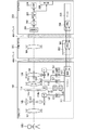
次に、図2を用いて、カメラ200、中間アダプタ300及び交換レンズ100を含むカメラシステムの間で構成される通信回路について説明する。本実施例のカメラシステムは、通信タイミングの通知に用いられる通知チャネルCSと、データ通信に用いられるデータ通信チャネルDATAを含む。
<Description of Configuration of Communication Circuit>
Next, a communication circuit configured between the camera system including the
図1で説明したように、カメラ200と中間アダプタ300は、マウント401を介して接続されている。マウント401には、少なくとも2つの通信端子が設けられている。また、中間アダプタ300と交換レンズ100は、マウント400を介して接続されている。マウント400には、少なくとも2つの通信端子が設けられている。各マウントに設けられた通信端子により、上述した通知チャネルCSとデータ通信チャネルDATAが形成される。
As described in FIG. 1, the
通知チャネルCSは、カメラマイコン205、アダプタマイコン302及びレンズマイコン111に接続されており、各マイコンは、通知チャネルCSの信号レベル(電圧レベル)を検出可能である。また、通知チャネルCSは、カメラ200内に配置された不図示の電源にプルアップ接続されている。さらに、通知チャネルCSは、カメラ200に含まれる接地スイッチ2081を介してグランドと接続可能であり、中間アダプタ300に含まれる接地スイッチ3031を介してグランドと接続可能である。通知チャネルCSは、交換レンズ100に含まれる接地スイッチ1121を介してグランドと接続可能である。
The notification channel CS is connected to the
このような回路構成を採用することで、カメラ200、中間アダプタ300及び交換レンズ100に含まれるいずれかの接地スイッチを接続状態(第1の設定)とすることにより、通知チャネルCSの信号レベルをLow(第1のレベル)とすることが可能である。また、カメラ200、中間アダプタ300及び交換レンズ100に含まれる全ての接地スイッチを遮断状態(第1の設定)とすることにより、通知チャネルCSの信号レベルをHigh(第2のレベル)とすることが可能である。
By adopting such a circuit configuration, the signal level of the notification channel CS can be set by setting one of the ground switches included in the
各マイコンは、接地スイッチの接続状態を変化させることで、通知チャネルCSとグランドとの接続状態を変化させることができる。換言すれば、各マイコンは接地スイッチの接続状態を変化させることで、通知チャネルCSの信号レベルをHighとLowのいずれかに設定可能である。 Each microcomputer can change the connection state between the notification channel CS and the ground by changing the connection state of the ground switch. In other words, each microcomputer can set the signal level of the notification channel CS to either High or Low by changing the connection state of the ground switch.
例えば、カメラマイコン205は、カメラ200に含まれる接地スイッチ2081を接続状態とすることで、通知チャネルCSの信号レベルをLowとすることができる。本発明では、接地スイッチを接続状態とすることを「通知チャネルCSにLow出力を行う」と記載する。また、接地スイッチを切断状態とすることを「通知チャネルCSにHigh出力を行う」と記載する。
For example, the
つまり、全てのマイコンが通知チャネルCSに対してHigh出力を行うことで、通知チャネルCSの信号レベルはHighとなる。一方、いずれかのマイコンが通知チャネルCSにLow出力を行うことで、通知チャネルCSの信号レベルはLowとなる。なお、データ通信時における通知チャネルCSの役割については後述する。 That is, when all the microcomputers output High to the notification channel CS, the signal level of the notification channel CS becomes High. On the other hand, when any one of the microcomputers outputs Low to the notification channel CS, the signal level of the notification channel CS becomes Low. The role of the notification channel CS in data communication will be described later.
データ通信チャネルDATAは、データの伝搬方向を切り替え可能な双方向のデータ通信チャネルである。データ通知チャネルDATAは、カメラマイコン205、アダプタマイコン302及びレンズマイコン111に接続されている。
The data communication channel DATA is a bidirectional data communication channel capable of switching the propagation direction of data. The data notification channel DATA is connected to the
データ通信チャネルDATAは、カメラ200に含まれる入出力切り替えスイッチ2082を介してカメラマイコン205と接続される。カメラマイコン205には、データを送信するためのデータ出力部とデータを受信するためのデータ入力部が備えられている。そして、入出力切り替えスイッチ2082の動作に応じて、データ通信チャネルDATAをデータ出力部とデータ入力部のうちの一方に選択的に接続することができる。
The data communication channel DATA is connected to the
また、データ通信チャネルDATAは、中間アダプタ300に含まれる入出力切り替えスイッチ3032を介してアダプタマイコン302と接続される。アダプタマイコン302には、データを送信するためのデータ出力部とデータを受信するためのデータ入力部が備えられている。そして、入出力切り替えスイッチ3032の動作に応じて、データ通信チャネルDATAをデータ出力部とデータ入力部のうちの一方に選択的に接続することができる。
Further, the data communication channel DATA is connected to the
データ通信チャネルDATAは、交換レンズ100に含まれる入出力切り替えスイッチ1122を介してレンズマイコン111と接続される。レンズマイコン111には、データを送信するためのデータ出力部とデータを受信するためのデータ入力部が備えられている。そして、入出力切り替えスイッチ1122の動作に応じて、データ通信チャネルDATAをデータ出力部とデータ入力部のうちの一方に選択的に接続することができる。このような回路構成を採用することにより、データ通信チャネルDATAのデータの伝搬方向を適切に切り替えることができる。
The data communication channel DATA is connected to the
<データフォーマットの説明>
続いて図3を用いて、データ通信チャネルDATAを介して通信されるデータのフォーマットについて説明する。
<Description of data format>
Subsequently, the format of data communicated via the data communication channel DATA will be described with reference to FIG.
図3は、データ送信側とデータ受信側の双方で通信速度を予め設定し、この設定に基づいた通信ビットレートでデータ通信を行う調歩同期式の通信方式におけるデータフォーマットを示している。通信ビットレートとは、1秒間に転送することができるデータ量を示し、単位はbps(bit per second)で表される。図3は最小通信単位である1フレームの信号波形を示している。 FIG. 3 shows a data format in the asynchronous communication system in which communication speeds are set in advance on both the data transmission side and the data reception side and data communication is performed at a communication bit rate based on the settings. The communication bit rate indicates the amount of data that can be transferred in one second, and the unit is expressed in bps (bits per second). FIG. 3 shows a signal waveform of one frame which is a minimum communication unit.
データ通信を行っていない状態では、データ通信チャネルDATAの信号レベルはHighレベルに維持されている。続いて、データの送信開始をデータ受信側に通知するため、データ通信チャネルDATAの信号レベルが1ビット期間の間Lowとされる。この1ビット期間をスタートビットSTと呼び、スタートビットSTからデータフレームが開始される。スタートビットSTに続く2ビット目から9ビット目までの8ビット期間で1バイトのデータが送信される。 When data communication is not performed, the signal level of the data communication channel DATA is maintained at the high level. Subsequently, in order to notify the data reception side of the start of data transmission, the signal level of the data communication channel DATA is kept low for one bit period. This one bit period is called start bit ST, and a data frame is started from the start bit ST. One byte of data is transmitted in an 8-bit period from the second bit to the ninth bit following the start bit ST.
データのビット配列はMSB(Most Significant Bit)ファーストフォーマットとして、最上位のデータD7から始まり、順にデータD6、データD5と続き、最下位のデータD0で終了する。そして、10ビット目に1ビットのパリティー情報(PA)を付加し、1フレームの最後を示すストップビットSPの期間、データ通信チャネルDATAの信号レベルがHighとされる。これにより、スタートビットSTから開始されたデータフレーム期間が終了する。なお、パリティー情報は1ビットである必要はなく、複数のビットのパリティー情報が付加されても良い。また、パリティー情報は必須ではなく、パリティー情報が付加されないフォーマットとしても良い。 The bit arrangement of data starts from the most significant data D7 as MSB (Most Significant Bit) first format, continues to data D6 and data D5 in order, and ends with the least significant data D0. Then, parity information (PA) of 1 bit is added to the 10th bit, and the signal level of the data communication channel DATA is made High during a stop bit SP indicating the end of 1 frame. As a result, the data frame period started from the start bit ST ends. The parity information does not have to be 1 bit, and parity information of a plurality of bits may be added. Also, parity information is not essential, and may be a format to which parity information is not added.
また、データのビット配列をLSB(Least Significant Bit)ファーストフォーマットとして、最下位のデータD0から始まり、順にデータD1、データD2と続き、最上位のデータD7で終了するようにしても良い。本実施例では、8ビット期間で1バイトのデータが送信されるが、8ビット以外のビット期間で1バイトのデータが送信されるようにしても良い。 Alternatively, the bit arrangement of data may be LSB first (Least Significant Bit) format, starting with the lowest data D0, continuing with the data D1, data D2 in order, and ending with the highest data D7. In this embodiment, one byte of data is transmitted in eight bit periods, but one byte of data may be transmitted in bit periods other than eight bits.
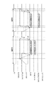
<ブロードキャスト通信の説明>
図4を用いて、ブロードキャスト通信について説明する。ブロードキャスト通信では、カメラ200が通信マスタとなり、中間アダプタ300及び交換レンズ100を通信スレーブとした通信が行われる。
<Description of broadcast communication>
Broadcast communication will be described with reference to FIG. In broadcast communication, communication is performed in which the
図4は、ブロードキャスト通信においてやり取りされる信号波形を示している。通信マスタであるカメラ200のカメラマイコン205は、通知チャネルCSにLow出力を行うことで、通信スレーブであるレンズマイコン111及びアダプタマイコン302に対してブロードキャスト通信の開始を通知する。
FIG. 4 shows signal waveforms exchanged in broadcast communication. The
次に、カメラマイコン205は、データ通信チャネルDATAを介してレンズマイコン111及びアダプタマイコン302にデータを送信する。
Next, the
一方、レンズマイコン111とアダプタマイコン302は、データ通信チャネルDATAを介して上述したスタートビットSTを検出することに応じて、通知チャネルCSにLow出力を行う。なお、レンズマイコン111とアダプタマイコン302が通知チャネルCSにLow出力を行う時点で、カメラマイコン205がLow出力を行っているため、通知チャネルCSの信号レベルはLowのままである。
On the other hand, the
レンズマイコン111及びアダプタマイコン302は、通知チャネルCSにLow出力を行うことで、通信待機要求を通知する。通信待機要求は、カメラシステムにおける通信を一時停止させるためのものであり、通知チャネルCSの信号レベルにより通信待機要求の有無が判断される。
The
カメラマイコン205は、全てのデータを送信した後に通知チャネルCSにHigh出力を行う。レンズマイコン111及びアダプタマイコン302は、データ通信チャネルDATAから送信されたストップビットSPを受信した後に、受信したデータの解析及び受信データに対応する内部処理を実行する。その後、次の通信を実行するための準備が整った後に通知チャネルCSにHigh出力を行う。
After transmitting all data, the
カメラシステムを構成する全ての構成要素が通知チャネルCSにHigh出力を行うことで、通知チャネルCSの信号レベルはHighとなる。カメラマイコン205、レンズマイコン111及びアダプタマイコン302は、通知チャネルCSの信号レベルがHighに戻ったことにより、カメラシステムを構成する各構成要素が次の通信を実行可能な状態になったことを確認することができる。
The signal level of the notification channel CS becomes High when all the components constituting the camera system output the High to the notification channel CS. The
図4では、カメラマイコン205が送信するデータに、アダプタマイコン302に対する送信要求命令が含まれており、カメラマイコン205によるデータ送信に続いて、アダプタマイコン302によるデータ送信が行われる。
In FIG. 4, the data transmitted by the
具体的には、通知チャネルCSの信号レベルがHighになった後に、アダプタマイコン302は、通知チャネルCSにLow出力を行う。これにより、レンズマイコン111及びカメラマイコン205に対してブロードキャスト通信の開始を通知する。次に、アダプタマイコン302は、データ通信チャネルDATAを介してレンズマイコン111及びカメラマイコン205にデータを送信する。
Specifically, after the signal level of the notification channel CS becomes high, the
一方、レンズマイコン111とカメラマイコン205は、データ通信チャネルDATAを介して上述したスタートビットSTを検出することに応じて、通知チャネルCSにLow出力を行う。なお、レンズマイコン111とカメラマイコン205が通知チャネルCSにLow出力を行う時点では、アダプタマイコン302が通知チャネルCSにLow出力を行っているため、通知チャネルCSの信号レベルはLowのままである。
On the other hand, the
アダプタマイコン302は、全てのデータを送信した後に通知チャネルCSにHigh出力を行う。レンズマイコン111及びカメラマイコン205は、データ通信チャネルDATAから送信されたストップビットSPを受信した後に、受信したデータの解析及び受信データに対応する内部処理を実行する。その後、次の通信を実行するための準備が整った後に通知チャネルCSにHigh出力を行う。
The
カメラシステムを構成する全ての構成要素が通知チャネルCSにHigh出力を行うことで、通知チャネルCSの信号レベルはHighとなる。カメラマイコン205、レンズマイコン111及びアダプタマイコン302は、通知チャネルCSの信号レベルがHighに戻ったことにより、カメラシステムを構成する各構成要素が次の通信を実行可能な状態になったことを確認することができる。
The signal level of the notification channel CS becomes High when all the components constituting the camera system output the High to the notification channel CS. The
以上説明したように、ブロードキャスト通信においては、データ送信側が、通知チャネルCSにLow出力を行って通知チャネルCSの信号レベルをHighからLowにすることで、ブロードキャスト通信の開始をデータ受信側に通知している。また、データ受信側は、通知チャネルCSへの出力をLow出力からHigh出力に変化させることで、通信待機要求の解除をレンズシステムの各構成要素に通知している。 As described above, in the broadcast communication, the data transmission side notifies the start of the broadcast communication to the data reception side by outputting Low to the notification channel CS and changing the signal level of the notification channel CS from High to Low. ing. Further, the data receiving side notifies each component of the lens system of the release of the communication standby request by changing the output to the notification channel CS from the low output to the high output.
なお、図4では本発明におけるブロードキャスト通信の通信波形の一例を示したが、本発明はこれに限定されない。例えば、1回のブロードキャスト通信において送受信されるデータを1バイトのデータでなく、複数バイトのデータとしても良い。 Although FIG. 4 shows an example of the communication waveform of the broadcast communication in the present invention, the present invention is not limited to this. For example, data transmitted and received in one broadcast communication may be data of multiple bytes instead of data of one byte.
また、通信方式をブロードキャスト通信からP2P通信に切り替える場合は、カメラマイコン205からレンズマイコン111及びアダプタマイコン302に対して、通信方式の切り替えを指示するデータの送信のみが行われる。
When the communication method is switched from broadcast communication to P2P communication, only transmission of data instructing switching of the communication method is performed from the
<P2P通信の説明>
図5を用いて、本発明における第2通信方式としてのP2P通信について説明する。P2P通信では、カメラ200が通信マスタとなり、カメラシステムを構成する構成要素の中で通信スレーブとして選択された1つの構成要素と1対1の個別の通信が行われる。
<Description of P2P communication>
P2P communication as a second communication method in the present invention will be described with reference to FIG. In P2P communication, the
図5は、P2P通信においてやり取りされる信号波形を示している。ここでは通信スレーブとして交換レンズ100が選択されている例を示している。P2P通信における通信スレーブを示す情報は、ブロードキャスト通信によって送信される。P2P通信においては、データ送信側が、通知チャネルCSにLow出力を行わず、通知チャネルCSをHighに維持したままデータ受信側にデータを送信する。すなわち、カメラ200から交換レンズ100、アダプタ300にデータを送信する間の通知チャネルCSの電圧レベルを、ブロードキャスト通信とP2P通信とで異ならせている。
FIG. 5 shows signal waveforms exchanged in P2P communication. Here, an example in which the
ブロードキャスト通信からP2P通信への切り替えが実行されると、最初に通信マスタであるカメラマイコン205からのデータ送信が開始される。
When switching from broadcast communication to P2P communication is performed, data transmission from the
図5は、カメラマイコン205からレンズマイコン111への1バイトのデータ送信後に、レンズマイコン111からカメラマイコン205に対して2バイトのデータ送信が行われる例を示している。
FIG. 5 shows an example in which 2-byte data transmission is performed from the
カメラシステムを構成する各構成要素においてブロードキャスト通信からP2P通信への切り替えが完了した後に、通信マスタとしてのカメラマイコン205はデータ通信チャネルDATAを介してレンズマイコン111にデータを送信する。カメラマイコン205は、データ送信が完了すると、通知チャネルCSの信号レベルをLow出力にして通信待機要求の通知を行う。そして、カメラマイコン205は、データ受信側としてデータを受信する準備が完了した後に通知チャネルCSの信号レベルをHigh出力に戻す。
After switching from broadcast communication to P2P communication is completed in each component constituting the camera system, the
一方、レンズマイコン111は、通知チャネルCSの信号レベルがLowになったことによりカメラマイコン205からのデータ送信が完了したことを認識し、受信したデータの解析や受信したデータに対応する内部処理を実行する。図5の例では、カメラマイコン205から受信したデータに、レンズマイコン111からカメラマイコン205へのデータ送信要求が含まれており、レンズマイコン111はカメラマイコン205に送信するデータの生成も行う。
On the other hand, the
その後、通知チャネルCSの信号レベルがHighに戻ったことにより、通信待機要求の解除を認識したレンズマイコン111は、カメラマイコン205に対して2バイトのデータ送信を行う。
Thereafter, when the signal level of the notification channel CS returns to High, the
レンズマイコン111は、データ送信が終了すると、通知チャネルCSの信号レベルをLow出力にして通信待機要求の通知を行う。そして、レンズマイコン111は、データ受信側としてデータを受信する準備が完了した後に通知チャネルCSの信号レベルをHigh出力に戻す。なお、P2P通信の通信相手として選択されていないアダプタマイコン302は、通知チャネルCSへの出力を変化させず、データの送受信に関与しない。
When the data transmission is completed, the
レンズマイコン111は、通知チャネルCSの信号レベルをHighに戻した後のカメラマイコン205からのデータ送信タイミングによって、P2P通信が継続されているのか、ブロードキャスト通信への切り替えが行われたのかを判断する。通知チャネルCSの信号レベルがHighのままの状態で、カメラマイコン205からのデータを受信した場合、レンズマイコン111はP2P通信が継続されていると判断する。一方、通知チャネルCSの信号レベルがLowに変化した後に、カメラマイコン205からのデータを受信した場合、レンズマイコン111はP2P通信からブロードキャスト通信に切り換えられたと判断する。
The
以上説明したように、P2P通信においては、データ送信側が通知チャネルCSの信号レベルをHigh出力からLow出力にすることで、データ送信側によるデータの送信が完了したことをデータ受信側に通知している。そのため、P2P通信においては、データ送信側が通知チャネルCSの信号レベルを変化させるまで、複数のデータフレームを連続して送信することができる。通信スレーブが1つのデータフレームを送信する毎に通信マスタからの通信が挿入されるシステム構成ではないため、カメラマイコン205と、レンズマイコン111やアダプタマイコン302等のアクセサリ装置との間の通信を高速に行うことができる。本カメラシステムでは、データの送信後に通知チャネルCSの電圧レベルが変化するように、カメラマイコン205、レンズマイコン111、アダプタマイコン302が通知チャネルCSの接地または非接地を切り替える。このような通知チャネルCSの電圧レベルの変化を、データの送信側と受信側との切り替えの合図としている。そして、データ送信側は、次の通信におけるデータ受信側としてのデータ受信準備が完了するまで、通知チャネルCSの信号レベルをLow出力のままとすることで、通信待機要求を通知している。
As described above, in P2P communication, the data transmission side notifies the data reception side that transmission of data by the data transmission side is completed by changing the signal level of the notification channel CS from High output to Low output. There is. Therefore, in P2P communication, a plurality of data frames can be transmitted continuously until the data transmission side changes the signal level of the notification channel CS. Since the system configuration is such that communication from the communication master is inserted each time the communication slave transmits one data frame, high-speed communication between the
<通信方式の切り替えについての説明>
図6を用いて、ブロードキャスト通信とP2P通信を切り替えて実行される通信の概要を説明する。ブロードキャスト通信とP2P通信のいずれの通信においてもカメラ200が通信マスタとなり、中間アダプタ300や交換レンズ100との通信を実行する。P2P通信におけるカメラ本体との通信相手を示す情報は、ブロードキャスト通信において通知される。
<Description of switching communication method>
The outline of communication performed by switching between broadcast communication and P2P communication will be described using FIG. The
図6は、ブロードキャスト通信とP2P通信を切り替えて実行される通信における通信波形を示している。初めに、P2P通信における通信相手としてアダプタマイコン302が選択されたことを示す情報がブロードキャスト通信において送受信され、その後、カメラマイコン205とアダプタマイコン302の間でP2P通信が行われる。以下、P2P通信における通信相手を示す情報を、通信相手指定データと記載する。
FIG. 6 shows communication waveforms in communication performed by switching between broadcast communication and P2P communication. First, information indicating that the
以下、通信相手指定データ自体に、ブロードキャスト通信からP2P通信への切り替えコマンドとしての機能を持たせた実施例について説明する。なお、通信相手指定データとは別に、ブロードキャスト通信からP2P通信への切り替えを指示する信号を送受信することでP2P通信への切り替えを実行しても良い。 The following describes an embodiment in which the communication partner specification data itself has a function as a switching command from broadcast communication to P2P communication. Note that switching to P2P communication may be performed by transmitting and receiving a signal instructing switching from broadcast communication to P2P communication separately from the communication partner specification data.
P2P通信における通信相手として選択されていないレンズマイコン111は通信相手指定データを受信した後、カメラマイコン205から受信したデータの解析や内部処理が終了した時点で通知チャネルCSにHigh出力を行う。そして、カメラマイコン205とアダプタマイコン302の間でP2P通信が行われている期間は、通知チャネルCSへの出力を変化させることなく、ブロードキャスト通信に対応した設定を維持する。
The
具体的には、アダプタマイコン302は、P2P通信への切り替えが完了すると、通知チャネルCSにHigh出力を行うことで、通信方式の切り替え完了をカメラマイコン205に通知する。カメラマイコン205も、P2P通信への切り替えが完了すると、通知チャネルCSにHigh出力を行う。上述したように、P2P通信における通信相手として選択されていないレンズマイコン111は、カメラマイコン205から受信したデータの解析や内部処理が終了した時点で通知チャネルCSにHigh出力を行う。
Specifically, when the switching to the P2P communication is completed, the
カメラマイコン205は、通知チャネルCSの信号レベルがHighになったことを検出すると、図5で示したP2P通信を開始する。P2P通信方式における通信の概要は図5で説明した通りであるため、ここではP2P通信の詳細についての説明を割愛する。
When the
カメラマイコン205とアダプタマイコン302の間のP2P通信が終了すると、カメラマイコン205はブロードキャスト通信により、P2P通信における通信相手としてレンズマイコン111を選択したことを示す通信相手指定データを送信する。その後、カメラマイコン205とレンズマイコン111の間でP2P通信が行われる。
When P2P communication between the
なお、アダプタマイコン302は、カメラマイコン205からデータが送信される前に通知チャネルCSの信号レベルがLowになったことにより、P2P通信からブロードキャスト通信への切り替えが実行されたことを認識する。
The
<ブロードキャスト通信における通信フローの説明>
次に、図7を用いて、ブロードキャスト通信における通信フローについて説明する。カメラマイコン205及びアダプタマイコン302は、コンピュータプログラムである通信制御プログラムに従って、図7のフローチャートに示す通信制御を行う。なお、図7において「S」はステップを意味する。図7では通信マスタとしてのカメラマイコン205の通信フローと、通信スレーブとしてのアダプタマイコン302の通信フローを開示している。レンズマイコン111の通信フローは、アダプタマイコン302の通信フローとほぼ同じであるため、ここではレンズマイコン111の通信フローを開示していない。
<Description of communication flow in broadcast communication>
Next, a communication flow in broadcast communication will be described using FIG. The
カメラマイコン205は、S100においてブロードキャスト通信を開始するイベントが発生したか否かの判定を行う。ブロードキャスト通信を開始するイベントが発生した場合はS101に進み、このようなイベントが発生していない場合は、S100の判定を繰り返し行う。
The
S101では、通知チャネルCSにLow出力を行い、通知チャネルCSの信号レベルをLowにすることで、レンズマイコン111及びアダプタマイコン302に対してブロードキャスト通信の開始を通知する。続いて、S102において、入出力切り替えスイッチ2082を動作させることで、データ通信チャネルDATAをカメラマイコン205のデータ出力部に接続し、S103においてデータ送信を開始する。
In S101, Low is output to the notification channel CS, and the signal level of the notification channel CS is set to Low, thereby notifying the
S104では、S103でカメラマイコン205から送信したデータに、送信要求コマンドが含まれるか否かの判定を行う。送信要求コマンドとは、通信マスタとしてのカメラマイコン205から送信されたデータを受信した通信スレーブに対して、カメラマイコン205へのデータ送信を要求するコマンドである。
In S104, it is determined whether the data transmitted from the
S103でカメラマイコン205から送信したデータに送信要求コマンドが含まれていない場合には、S105に進む。S105では、カメラマイコン205からのデータ送信の完了後に通知チャネルCSへのLow出力を解除し、S116に進む。
If the transmission request command is not included in the data transmitted from the
S103でカメラマイコン205から送信したデータに送信要求コマンドが含まれている場合にはS106に進む。S106では、カメラマイコン205からのデータ送信の完了後に、データ通信チャネルDATAをカメラマイコン205のデータ入力部に接続し、S107に進む。S107では、通知チャネルCSへのLow出力を解除し、High出力を行う。
When the transmission request command is included in the data transmitted from the
S108では、通知チャネルCSの信号レベルがHighになったか否かの判定を行う。この判定は、通知チャネルCSの信号レベルがHighになるまで継続して行われる。通知チャネルCSの信号レベルがHighのときには、カメラシステムが通信可能な状態であることを示している。通知チャネルCSの信号レベルがHighになると、S109において通知チャネルCSの信号レベルがLowになったか否かの判定を行う。この判定は、通知チャネルCSの信号レベルがLowになるまで継続して行われる。 In S108, it is determined whether the signal level of the notification channel CS has become High. This determination is continuously performed until the signal level of the notification channel CS becomes High. When the signal level of the notification channel CS is High, it indicates that the camera system can communicate. When the signal level of the notification channel CS becomes High, it is determined in S109 whether the signal level of the notification channel CS has become Low. This determination is continuously performed until the signal level of the notification channel CS becomes low.
通知チャネルCSの信号レベルがLowになることに応じて、通信スレーブであるアダプタマイコン302からカメラマイコン205への通信が開始される。通知チャネルCSの信号レベルがLowになったと判定した後に、カメラマイコン205はS110においてデータ通信チャネルDATAにおけるデータの受信を許可する。続いて、S111において、アダプタマイコン302から送信されるデータに含まれるスタートビットを受信したか否かの判定を行う。この判定は、スタートビットを受信するまで継続して行われる。
In response to the signal level of the notification channel CS becoming Low, communication from the
スタートビットを受信すると、S112に進み、通知チャネルCSにLow出力を行い、S113においてストップビットを受信したか否かの判定を行う。この判定は、ストップビットを受信するまで継続して行われる。ストップビットを受信すると、S114においてデータ通信チャネルDATAにおけるデータの受信を禁止し、受信したデータの解析や受信したデータに対応する内部処理を実行する。その後、S115において通知チャネルCSへのLow出力を解除し、High出力を行う。 If the start bit is received, the process proceeds to step S112, the Low is output to the notification channel CS, and it is determined whether the stop bit is received in step S113. This determination is continuously performed until the stop bit is received. When the stop bit is received, the reception of data in the data communication channel DATA is inhibited in S114, and analysis of the received data and internal processing corresponding to the received data are executed. Thereafter, the low output to the notification channel CS is canceled in S115, and the High output is performed.
続いて、S116において、通知チャネルCSの信号レベルがHighになったか否かの判定を行う。この判定は、通知チャネルCSの信号レベルがHighになるまで継続して行われる。通知チャネルCSの信号レベルがHighになると、S117において、S103で送信したデータが、通信相手指定データであったか否かの判定を行う。通信相手指定データであった場合には、S118に進み、P2P通信への移行を行う。通信相手指定データでなかった場合には、ブロードキャスト通信を継続する。 Subsequently, in S116, it is determined whether the signal level of the notification channel CS has become High. This determination is continuously performed until the signal level of the notification channel CS becomes High. When the signal level of the notification channel CS becomes High, it is determined in S117 whether the data transmitted in S103 is communication partner specification data. If it is the communication partner designation data, the process proceeds to S118, and the transition to P2P communication is performed. If it is not the communication partner designation data, the broadcast communication is continued.
次に、アダプタマイコン302における通信フローについて説明する。S200において、通知チャネルCSの信号レベルがLowになったか否かの判定を行う。この判定は、通知チャネルCSの信号レベルがLowになるまで継続して行われる。通知チャネルCSの信号レベルがLowになることに応じて、通信マスタであるカメラマイコン205からのデータ送信が開始されるため、S201においてアダプタマイコン302はデータ通信チャネルDATAにおけるデータの受信を許可する。
Next, the communication flow in the
続いて、S202においてスタートビットを受信したか否かの判定を行う。スタートビットを受信していない場合には、S203に進み、通知チャネルCSの信号レベルがHighであるか否かの判定を行う。 Subsequently, it is determined whether or not the start bit is received in S202. If the start bit has not been received, the process proceeds to S203, and it is determined whether the signal level of the notification channel CS is High.
ここで、S203及びS204の処理を行うのは、カメラマイコン205とレンズマイコン111の間でP2P通信が行われ、アダプタマイコン302のみがブロードキャスト通信を行う状況に対応するためである。この状況では、アダプタマイコン302はカメラマイコン205からデータを受信することはないため、S204においてデータ通信チャネルDATAにおけるデータの受信を禁止する。
Here, the processing of S203 and S204 is performed in order to cope with a situation in which only the
<P2P通信>の欄で説明したように、P2P通信においても通知チャネルCSの信号レベルはHighとLowの間で変化する。通知チャネルCSの信号レベルは、通常時はHighであり、ブロードキャスト通信においては、通信待機要求を通知する場合や、通信の開始を通知する場合にLowに設定される。P2P通信においては、通信待機要求を通知する場合にLowに設定される。 As described in the section <P2P Communication>, the signal level of the notification channel CS changes between High and Low also in P2P communication. The signal level of the notification channel CS is normally High, and in broadcast communication, it is set to Low when notifying a communication standby request or notifying of the start of communication. In P2P communication, it is set to Low when notifying a communication standby request.
S202において、アダプタマイコン302がカメラマイコン205からスタートビットを受信していない状況としては、以下の状況が考えられる。
As a situation where the
1つ目の状況は、カメラマイコン205が通知チャネルCSの信号レベルをLowにした後であって、データ送信が開始されていない状況である。2つ目の状況は、カメラマイコン205とレンズマイコン111がP2P通信を行っており、アダプタマイコン302はP2P通信に関与していない状況である。
The first situation is a situation where the data transmission has not been started after the
1つ目の状況の場合には、通知チャネルCSの信号レベルはHighにならないため、S203からS202に戻り、カメラマイコン205からのデータ送信が開始されるまで、S202及びS203の判定を繰り返す。
In the first situation, the signal level of the notification channel CS does not become High, so the process returns from S203 to S202, and the determinations in S202 and S203 are repeated until data transmission from the
2つ目の状況の場合には、カメラマイコン205とレンズマイコン111のいずれかが通信待機要求を通知していない限り、通知チャネルCSの信号レベルはHighになっている。この状況では、基本的にはS203からS204に進み、データ通信チャネルDATAにおけるデータの受信が禁止される。なお、P2P通信において、通信待機要求が通知されている場合には、S203からS202に戻り、再びS203の判定が行われることになる。S203の判定が複数回実施されることはあるが、通信待機要求が解除され、通知チャネルCSの信号レベルがHighになると、S203からS204に進むことになる。
In the second situation, the signal level of the notification channel CS is High unless one of the
以上のように、S203及びS204の制御フローを追加することで、カメラシステムの中でブロードキャスト通信とP2P通信を併用することができる。本実施例においては、カメラマイコン205とレンズマイコン111の間でP2P通信を行う一方で、ブロードキャスト通信に対応した状態でアダプタマイコン302を待機させることができる。
As described above, by adding the control flow of S203 and S204, broadcast communication and P2P communication can be used together in the camera system. In the present embodiment, while P2P communication is performed between the
S202の説明に戻る。S202においてスタートビットを受信すると、アダプタマイコン302は、受信したデータの解析や受信したデータに対応する内部処理を開始すると共に、通知チャネルCSにLow出力を行う。これにより、カメラシステムを構成する各構成要素に対して通信待機要求を通知する。
The description returns to S202. When the start bit is received in S202, the
次に、S206においてストップビットを受信したか否かの判定を行う。この判定は、ストップビットを受信するまで継続して行われる。ストップビットを受信すると、S207においてデータ通信チャネルDATAにおけるデータの受信を禁止し、受信したデータの解析や受信したデータに対応する内部処理を継続する。データの内部処理が完了し、次のデータ通信を実行可能な状態となると、S208において通知チャネルCSへのLow出力を解除し、High出力を行う。 Next, in S206, it is determined whether the stop bit has been received. This determination is continuously performed until the stop bit is received. When the stop bit is received, the reception of data in the data communication channel DATA is inhibited in S207, and analysis of the received data and internal processing corresponding to the received data are continued. When the internal processing of data is completed and the next data communication can be performed, the low output to the notification channel CS is canceled in S208, and the High output is performed.
S209では、カメラマイコン205から受信したデータに、送信要求コマンドが含まれるか否かの判定を行う。送信要求コマンドを含む場合には、S210に進み、通知チャネルCSの信号レベルがHighになったか否かの判定を行う。この判定は、通知チャネルCSの信号レベルがHighになるまで継続して行われる。通知チャネルCSの信号レベルがHighのときには、カメラシステムが通信可能な状態であることを示している。カメラマイコン205から受信したデータに送信要求コマンドが含まれない場合には、後述するS215に進む。
In S209, it is determined whether the data received from the
S210において、通知チャネルCSの信号レベルがHighであると判定された場合にはS211に進む。S211では、通知チャネルCSにLow出力を行い、通知チャネルCSの信号レベルをLowにすることで、カメラマイコン205及びレンズマイコン111に対してブロードキャスト通信の開始を通知する。続いて、S212において、入出力切り替えスイッチ3032を動作させることで、データ通信チャネルDATAをアダプタマイコン302のデータ出力部に接続し、S213においてデータ送信を開始する。
When it is determined in S210 that the signal level of the notification channel CS is High, the process proceeds to S211. In S211, Low is output to the notification channel CS, and the signal level of the notification channel CS is set to Low, thereby notifying the
データ送信が完了すると、S214において、通知チャネルCSへのLow出力を解除し、High出力を行う。続いて、S215では、通知チャネルCSの信号レベルがHighになったか否かの判定を行う。この判定は、通知チャネルCSの信号レベルがHighになるまで継続して行われる。 When the data transmission is completed, the low output to the notification channel CS is released in S214, and the High output is performed. Subsequently, in S215, it is determined whether the signal level of the notification channel CS has become High. This determination is continuously performed until the signal level of the notification channel CS becomes High.
通知チャネルCSの信号レベルがHighになるとS216に進む。S216では、カメラマイコン205から受信したデータが通信相手指定データであり、かつ、自身がP2P通信におけるカメラマイコン205の通信相手として選択されたか否かの判定を行う。P2P通信におけるカメラマイコン205の通信相手としてアダプタマイコン302が選択された場合には、S217に進み、データ通信チャネルDATAにおけるデータ受信を許可する。そして、S218において、ブロードキャスト通信からP2P通信への移行を行う。
When the signal level of the notification channel CS becomes High, the process proceeds to S216. In S216, it is determined whether the data received from the
カメラマイコン205から受信したデータが通信相手指定データでない場合、またはP2P通信における通信相手としてアダプタマイコン302が選択されていない場合は、P2P通信への移行を実行することなく、ブロードキャスト通信を継続する。
If the data received from the
<P2P通信における通信フロー>
次に、図8を用いて、P2P通信における通信フローについて説明する。カメラマイコン205及びレンズマイコン111は、コンピュータプログラムである通信制御プログラムに従って、図8のフローチャートに示す通信制御を行う。なお、図8において「S」はステップを意味する。図8では通信マスタとしてのカメラマイコン205の通信フローと、通信スレーブとしてのレンズマイコン111の通信フローを開示している。アダプタマイコン302の通信フローは、レンズマイコン111の通信フローとほぼ同じであるため、ここではアダプタマイコン302の通信フローを開示していない。
<Communication flow in P2P communication>
Next, a communication flow in P2P communication will be described using FIG. The
カメラマイコン205は、S300においてP2P通信を開始するイベントが発生したか否かの判定を行う。P2P通信を開始するイベントが発生した場合はS301に進み、このようなイベントが発生していない場合は、S300の判定を繰り返し行う。
The
S301では、入出力切り替えスイッチ2082を動作させることで、データ通信チャネルDATAをカメラマイコン205のデータ出力部に接続し、S302においてデータ送信を開始する。
In S301, the data communication channel DATA is connected to the data output unit of the
S303では、通知チャネルCSにLow出力を行い、通知チャネルCSの信号レベルをLowにする。これにより、カメラマイコン205は、通信スレーブであるレンズマイコン111に対して通信待機要求を行う。通知チャネルCSの信号レベルがLowの期間、レンズマイコン111はカメラマイコン205に対するデータ送信を行わない。
In S303, Low is output to the notification channel CS, and the signal level of the notification channel CS is set to Low. Thus, the
S304では、S302でカメラマイコン205から送信したデータに、送信要求コマンドが含まれるか否かの判定を行う。送信要求コマンドとは、通信スレーブに対して、カメラマイコン205へのデータ送信を要求するコマンドである。S302でカメラマイコン205から送信したデータに送信要求コマンドが含まれない場合には、レンズマイコン111からデータが送信されることはない。この場合、S304からS305に進み、レンズマイコン111が通信待機要求を通知しているか否かを確認する。
In S304, it is determined whether the data transmitted from the
具体的には、S305において、カメラマイコン205における通知チャネルCSへのLow出力を解除した上で、S306において通知チャネルCSの信号レベルがLowであるか否かの判定を行う。これにより、レンズマイコン111が通知チャネルCSの信号レベルをLowにしているか否か、つまり、レンズマイコン111が通信待機要求を通知しているか否かを判定することができる。
Specifically, after the Low output to the notification channel CS in the
一般的に、カメラマイコン205からのデータを受信したレンズマイコン111は、そのデータの解析や内部処理のために、ある程度の期間、通知チャネルCSにLow出力を行うことで通信待機要求を通知する。S306は、レンズマイコン111の通知待機要求を認識するために行われる。S305の後に一時的に通知チャネルCSの信号レベルがHighとなることがある。このときは、S306の判定を行うことで通知チャネルCSの信号レベルがLowとなるまで待機する。S306で通知チャネルCSの信号レベルがLowとなったことを確認した上でS311に進む。
Generally, the
S304に戻る。S304において、S302でカメラマイコン205から送信したデータが送信要求コマンドである場合にはS307に進む。
It returns to S304. If the data transmitted from the
S307では、入出力切り替えスイッチ2082を動作させることで、データ通信チャネルDATAをカメラマイコン205のデータ入力部に接続する。さらに、S308において通知チャネルCSへのLow出力を解除し、High出力を行う。
In S307, the data communication channel DATA is connected to the data input unit of the
通知チャネルCSの信号レベルがHighの状態で、レンズマイコン111からのデータ受信を行い、S309において、通知チャネルCSの信号レベルがLowになったか否かの判定を行う。通知チャネルCSの信号レベルがLowになったことに応じて、レンズマイコン111のデータ送信が完了したと判断し、S310においてデータ解析を行う。
When the signal level of the notification channel CS is High, data reception from the
続いてS311において、通知チャネルCSの信号レベルがHighになったか否かの判定を行う。この判定は、通知チャネルCSの信号レベルがHighになるまで継続して行われる。通知チャネルCSの信号レベルがHighの状態は、通信スレーブとしてのレンズマイコン111がデータ通信可能な状態であることを意味している。
Subsequently, in S311, it is determined whether the signal level of the notification channel CS has become High. This determination is continuously performed until the signal level of the notification channel CS becomes High. The state in which the signal level of the notification channel CS is High means that the
通知チャネルCSの信号レベルがHighになると、S312に進み、ブロードキャスト通信への移行イベントが発生した否かの判定を行う。ブロードキャスト通信への移行イベントが発生した場合には、S313に進み、ブロードキャスト通信への移行を行う。ブロードキャスト通信への移行イベントが発生していない場合は、P2P通信を継続して行う。 When the signal level of the notification channel CS becomes High, the process proceeds to S312, and it is determined whether a transition event to broadcast communication has occurred. If a transition event to broadcast communication has occurred, the process advances to step S313 to shift to broadcast communication. If a transition event to broadcast communication has not occurred, P2P communication is continuously performed.
次に、通信スレーブとしてのレンズマイコン111の通信フローについて説明する。レンズマイコン111は、ブロードキャスト通信からP2P通信への切り替えを実行すると、最初にカメラマイコン205から送信されるデータの受信を行う。カメラマイコン205から送信されるデータを受信している期間、通知チャネルCSの信号レベルはHighに保たれている。
Next, the communication flow of the
続いてS400において、通知チャネルCSの信号レベルがLowになったか否かの判定を行う。通知チャネルCSの信号レベルがLowになったことに応じて、カメラマイコン205のデータ送信が完了したと判断し、S401においてデータ解析を行う。
Subsequently, in S400, it is determined whether the signal level of the notification channel CS has become Low. In response to the signal level of the notification channel CS becoming Low, it is determined that the data transmission of the
続いて、S402において、通知チャネルCSの信号レベルがHighになったか否かの判定を行う。この判定は、通知チャネルCSの信号レベルがHighになるまで継続して行われる。通知チャネルCSの信号レベルがLowの状態は、カメラマイコン205が通信待機要求を通知している状態である。
Subsequently, in S402, it is determined whether the signal level of the notification channel CS has become High. This determination is continuously performed until the signal level of the notification channel CS becomes High. When the signal level of the notification channel CS is Low, the
通知チャネルCSの信号レベルがHighになると、S403において、カメラマイコン205から受信したデータに、送信要求コマンドが含まれるか否かの判定を行う。カメラマイコン205から受信したデータに送信要求コマンドが含まれない場合にはS404に進む。
When the signal level of the notification channel CS becomes High, it is determined in S403 whether the data received from the
S404では、カメラマイコン205から受信したデータに対する内部処理等のために、通知チャネルCSの信号レベルをLowにすることで、カメラマイコン205に対して通信待機要求を通知する。レンズマイコン111が通信可能な状態となると、S405において通知チャネルCSの信号レベルをHighにして、通信待機要求を解除した上でS411に進む。
In S404, the communication standby request is notified to the
S403に戻る。S403において、カメラマイコン205から受信したデータに送信要求コマンドが含まれる場合にはS406に進む。S406では、入出力切り替えスイッチ1122を動作させることで、データ通信チャネルDATAをレンズマイコン205のデータ出力部に接続する。そしてS407において、カメラマイコン205へのデータ送信を開始する。
It returns to S403. If it is determined in step S403 that the data received from the
カメラマイコン205へのデータ送信が完了した後に、S408において、通知チャネルCSにLow出力を行い、通知チャネルCSの信号レベルをLowにする。これにより、レンズマイコン111は、通信マスタであるカメラマイコン205に対して通信待機要求を行う。通知チャネルCSの信号レベルがLowの期間、カメラマイコン205はレンズマイコン111に対するデータ送信を行わない。
After the data transmission to the
S409では、入出力切り替えスイッチ1122を動作させることで、データ通信チャネルDATAをレンズマイコン205のデータ入力部に接続し、S410において、通知チャネルCSへのLow出力を解除し、High出力を行う。
At S409, the data communication channel DATA is connected to the data input unit of the
S411では、通知チャネルCSの信号レベルがHighになったか否かの判定を行う。この判定は、通知チャネルCSの信号レベルがHighになるまで継続して行われる。通知チャネルCSの信号レベルがHighになった状態は、カメラマイコン205及びレンズマイコン111が通信可能な状態であることを意味している。
In S411, it is determined whether the signal level of the notification channel CS has become High. This determination is continuously performed until the signal level of the notification channel CS becomes High. The state in which the signal level of the notification channel CS is High means that the
以上説明したように、カメラ200から、交換レンズ100、アダプタ300にデータを送信する間の通知チャネルCSの電圧レベルを、ブロードキャスト通信とP2P通信とで異ならせている。このようなシステムにより、カメラ200が特定のアクセサリ装置と個別に通信を行う場合に、通信相手が変更されるまでは通信相手を改めて通知する必要がないため、カメラ200と、交換レンズ100やアダプタ300を含むアクセサリ装置との間の通信を高速に行うことができる。
As described above, the voltage level of the notification channel CS during transmission of data from the
<変形例>
以下、ブロードキャスト通信における図4とは異なる通信制御方法について説明する。図4のブロードキャスト通信においては、カメラマイコン205が通知チャネルCSにLow出力を行って、通知チャネルCSの信号レベルをLowにすることでブロードキャスト通信の開始を各通信スレーブに通知している。
<Modification>
Hereinafter, a communication control method different from that in FIG. 4 in broadcast communication will be described. In the broadcast communication of FIG. 4, the
図9に示した変形例は、通信スレーブとしてのレンズマイコン111やアダプタマイコン302が、ブロードキャスト通信の開始をカメラマイコン205にリクエストする態様を示している。カメラマイコン205への通信リクエストは、カメラマイコン205からアクセサリ装置に含まれるマイコンへの通信が一時停止された状態において、アクセサリ装置に含まれるマイコンが、カメラマイコン205との通信を主体的に再開させるときに実行される。
The modification shown in FIG. 9 shows a mode in which the
本変形例は、例えば、中間アダプタ300に備えられた操作部材304がユーザによって操作された場合に実行される。交換レンズ100に供えられた操作部材130がユーザによって操作された場合にも実行されうる。カメラシステムとして通信が一時停止された状態から通信を再開させる場合、基本的には、通信マスタであるカメラマイコン205が主体的に通信を再開させることが適切である。通信スレーブであるアクセサリ装置のマイコンに通信を再開させる機能を持たせることは、通信マスタであるカメラシステム205が予期しないタイミングでの通信再開が行われるおそれがある。それゆえ、通信スレーブに対して、無制限に通信を再開させる機能を持たせることは好ましくない。
This modification is performed, for example, when the
そこで、本変形例では、アクセサリ装置に含まれるマイコンが、カメラマイコン205への通信開始リクエストを行うという形で、通信スレーブであるアクセサリ装置のマイコンに、通信を再開させる機能を持たせている。
Therefore, in the present modification, the microcomputer included in the accessory device makes the microcomputer of the accessory device, which is the communication slave, have a function of resuming communication, in the form of making a communication start request to the
図9は、本変形例のブロードキャスト通信における通信波形を示している。本変形例の通信制御方法では、通信スレーブとしてのレンズマイコン111やアダプタマイコン302が、通信イベントの発生の有無を監視している。そして、通信イベントが発生した場合には、通知チャネルCSにLow出力を行うことで通知チャネルCSの信号レベルをLowにする。
FIG. 9 shows communication waveforms in the broadcast communication of this modification. In the communication control method of the present modification, the
カメラマイコン205は、通知チャネルCSの信号レベルがLowになったことに応じて、通知チャネルCSにLow出力を行った上でブロードキャスト通信を開始する。通知チャネルCSにLow出力を行った後のブロードキャスト通信のフローは、図4で説明したフローと同じであるため、ここでの説明は割愛する。
In response to the signal level of the notification channel CS becoming Low, the
以上説明した実施例は、通知チャネルCSとデータ通信チャネルDATAを含む通信チャネルに加え、別の通信チャネルと併用可能である。 The embodiment described above can be used in combination with another communication channel in addition to the communication channel including the notification channel CS and the data communication channel DATA.
その一例を、図10を用いて説明する。なお、図10において、図1と同一の部材には同一の符号を付し、重複する説明は省略する。また、図10において、図1に記載されている部材の一部の図示を省略している。前述の通知チャネルCSおよびデータ通信チャネルDATAは、第3通信という通信用の通信線である。 One example thereof will be described with reference to FIG. In FIG. 10, the same members as those in FIG. 1 are denoted by the same reference numerals, and redundant description will be omitted. Moreover, in FIG. 10, illustration of a part of members described in FIG. 1 is omitted. The aforementioned notification channel CS and data communication channel DATA are communication lines for communication called third communication.
レンズマイコン111は、通信部112に加え、第1通信を行うための通信部131、第2通信を行うための通信部132を制御する。カメラマイコン205は、通信部112に加え、第1通信を行うための通信部209、第2通信を行うための通信部210を制御する。
The
まず、第1通信について説明する。第1通信は、通信部131と通信部209を介して行われる通信である。通信部131はレンズマイコン111からの指示に基づいて、通信部209はカメラマイコン205からの指示に基づいて、通知チャネルCS1、データ通信チャネルDCL、データ通信チャネルDLCを介して通信を行う。通信部131および通信部209は、通知チャネルCS1の電圧レベル、調歩同期通信の際の通信レート(単位時間当たりのデータ量)や通信電圧の設定をする。さらに、レンズマイコン111やカメラマイコン205からの指示を受けて、データ通信チャネルDCLおよびデータ通信チャネルDLCを介したデータの送受信を行う。
First, the first communication will be described. The first communication is communication performed via the communication unit 131 and the
通知チャネルCS1は、カメラ本体200から交換レンズ100への通信要求の通知等に用いられる信号線である。データ通信チャネルDCLは、カメラ本体200から交換レンズ100にデータを送信する際に用いられるチャネルであり、データ通信チャネルDLCは交換レンズ100からカメラ本体200にデータを送信する際に用いられるチャネルである。
The notification channel CS1 is a signal line used for notifying a communication request from the
カメラマイコン205とレンズマイコン111は、第1通信では、クロック同期通信または調歩同期通信により通信を行う。交換レンズ100がカメラ本体200に接続された際に行われる初期通信も、まずは第1通信により行う。カメラマイコン205とレンズマイコン111は交換レンズ100の識別情報を通信し、カメラ本体200装着された交換レンズ100が調歩同期通信に対応可能であることが判明すると、クロック同期通信から調歩同期通信に通信方式を切り替える。また、識別情報の通信の結果、カメラマイコン205は、交換レンズ100が、アダプタ300も含めて通信を行う第3通信に対応可能かどうかを識別してもよい。カメラマイコン205は、交換レンズ100が第3通信に対応可能であると判断した場合、交換レンズ100や中間アダプタ300を認識するための認証通信をP2P通信を介して行ってもよい。
In the first communication, the
次に、第2通信について説明する。第2通信は、交換レンズ100からカメラ本体200への一方向の通信である。第2通信は、通信部132と通信部210を介して行われる。通信部132はレンズマイコン111からの指示に基づいて、通信部210はカメラマイコン205からの指示に基づいて、通知チャネルCS2とデータ通信チャネルDLC2を介して通信を行う。カメラ通信部208とレンズ通信部118は、クロック同期式通信や調歩同期通信によりデータを送受信する。第1通信のデータ通信チャネルDLCと共に第2通信チャネルのデータ通信チャネルDLC2を用いることで、交換レンズ100からカメラ本体200に対して大量のデータを短時間で送信することが可能となる。
Next, the second communication will be described. The second communication is one-way communication from the
以上説明した実施例は代表的な例に過ぎず、本発明の実施に際しては、各実施例に対して種々の変形や変更が可能である。例えば、上記実施例では、アクセサリ装置として交換レンズと中間アダプタを用いた例を示したが、アクセサリ装置として、カメラ本体に直接装着される交換レンズとカメラ本体に直接装着されるストロボ等を用いても良い。 The embodiments described above are only representative examples, and various modifications and changes can be made to the embodiments in implementing the present invention. For example, in the above embodiment, an example using an interchangeable lens and an intermediate adapter as an accessory device is shown, but as an accessory device, using an interchangeable lens directly attached to the camera body and a strobe directly attached to the camera body Also good.
100 交換レンズ(アクセサリ装置)
111 レンズマイコン(アクセサリ制御部)
200 カメラ
205 カメラマイコン(カメラ制御部)
300 中間アダプタ(アクセサリ装置)
302 アダプタマイコン(アクセサリ制御部)
CS 通知チャネル
DATA データ通信チャネル
100 Interchangeable Lens (Accessory Device)
111 Lens Microcomputer (Accessory Controller)
200
300 Intermediate Adapter (Accessory Device)
302 Adapter microcomputer (Accessory control unit)
CS notification channel DATA data communication channel
Claims (23)
前記カメラとの間で行う通信であり、且つ、データ通信に用いられるデータ通信チャネルと前記データ通信チャネルを介して行う通信の通信方式の通知に用いられる通知チャネルとを含むチャネルを用いた通信を制御するアクセサリ制御部を有し、
前記アクセサリ制御部は、
前記アクセサリ装置を含む、前記カメラに装着された複数のアクセサリ装置と、前記カメラとの間で通信するために用いられる第1通信方式と、前記カメラと個別に通信するために用いられ、前記カメラからデータを受信している間の前記通知チャネルの電圧レベルが前記第1通信方式とは異なる第2通信方式と、に切り替え可能であり、
前記第1通信方式において、前記第2通信方式における前記カメラの通信相手として前記アクセサリ装置が選択されたことを示す通信相手指定データを前記データ通信チャネルを介して受信したことに応じて、前記第1通信方式から前記第2通信方式への切り替えを行うことを特徴とするアクセサリ装置。 An accessory device that can be attached to a camera, and
Communication using a channel including communication between the camera and a data communication channel used for data communication and a notification channel used for notifying a communication method of communication performed via the data communication channel Has an accessory control unit to control
The accessory control unit
Said accessory comprising a device, and multiple accessory devices mounted on the camera, and a first communication scheme used for communication with the camera is used to communicate separately with the camera, the The voltage level of the notification channel can be switched to a second communication method different from the first communication method while receiving data from a camera,
In the first communication method, in response to reception of communication partner designation data indicating that the accessory device has been selected as a communication partner of the camera in the second communication method via the data communication channel, (1) An accessory device characterized by performing switching from the communication method to the second communication method.
前記複数のアクセサリ装置および前記カメラのいずれかが前記通知チャネルを前記第1の設定した場合と、前記複数のアクセサリ装置および前記カメラが前記通知チャネルを前記第2の設定とした場合とで、前記通知チャネルの電圧レベルは異なり、
前記アクセサリ制御部は、
前記第1通信方式において、前記カメラからデータを受信している間は前記通知チャネルを第1の設定とし、
前記第2通信方式において、前記カメラからデータを受信している間の少なくとも一部の期間で、前記通知チャネルを第2の設定とすることを特徴とする請求項1乃至11のいずれか1項に記載のアクセサリ装置。 The plurality of accessory devices and the camera can set the notification channel to a first setting and a second setting, respectively.
When any of the plurality of accessory devices and the camera set the first notification channel, and when the plurality of accessory devices and the camera set the second notification channel, The notification channel voltage levels are different
The accessory control unit
In the first communication method, while the data is received from the camera, the notification channel is set to a first setting,
12. The second communication method according to any one of claims 1 to 11, wherein the notification channel is set to a second setting during at least a part of the period during which data is received from the camera. Accessory device as described in.
前記第1のアクセサリ装置および前記第2のアクセサリ装置との間で行う通信であり、且つ、データ通信に用いられるデータ通信チャネルと前記データ通信チャネルを介して行う通信の通信方式の通知に用いられる通知チャネルとを含むチャネルを用いた通信を制御するカメラ制御部を有し、
前記カメラ制御部は、
前記第1のアクセサリ装置および前記第2のアクセサリ装置との間で通信するために用いられる第1通信方式と、前記第1のアクセサリ装置および前記第2のアクセサリ装置のうちの1つのアクセサリ装置と個別に通信するために用いられ、前記カメラからデータを送信する間の前記通知チャネルの電圧レベルが前記第1通信方式とは異なる第2通信方式と、に切り替え可能であり、
前記第1通信方式において、前記第1のアクセサリ装置および前記第2のアクセサリ装置に対して、前記データ通信チャネルを介して前記第2通信方式における前記カメラの通信相手を示す通信相手指定データを送信したことに応じて、前記第1通信方式から前記第2通信方式への切り替えを行うことを特徴とするカメラ。 A camera to which the first accessory device and the second accessory device can be attached,
Communication performed between the first accessory device and the second accessory device , and used to notify a data communication channel used for data communication and a communication method of communication performed via the data communication channel A camera control unit that controls communication using a channel including a notification channel;
The camera control unit
A first communication scheme used to communicate between the first accessory device and the second accessory device, and an accessory device of the first accessory device and the second accessory device The second communication method is used to individually communicate, and the voltage level of the notification channel can be switched to a second communication method different from the first communication method while data is transmitted from the camera.
In the first communication method, the communication partner designation data indicating the communication partner of the camera in the second communication method is transmitted to the first accessory device and the second accessory device via the data communication channel. A camera characterized by performing switching from the first communication method to the second communication method according to the above.
前記第1通信方式において、前記第1のアクセサリ装置および前記第2のアクセサリ装置にデータを送信している間の前記通知チャネルの電圧レベルを第1のレベルとし、
前記第2通信方式において、前記1つのアクセサリ装置にデータを送信している間の前記通知チャネルの電圧レベルを前記第1のレベルよりも高い第2のレベルとすることを特徴とする請求項13に記載のカメラ。 The camera control unit
In the first communication method, the voltage level of the notification channel is set to a first level while data is being transmitted to the first accessory device and the second accessory device,
In the second communication method, a voltage level of the notification channel while transmitting data to the one accessory device is set to a second level higher than the first level. Camera described in.
前記前記カメラ、前記第1のアクセサリ装置、および前記第2のアクセサリ装置の少なくともいずれかが前記通知チャネルを前記第1の設定した場合と、前記カメラ、前記第1のアクセサリ装置、および前記第2のアクセサリ装置が前記通知チャネルを前記第2の設定とした場合とで、前記通知チャネルの電圧レベルは異なり、
前記カメラ制御部は、
前記第1通信方式において、前記第1のアクセサリ装置および前記第2のアクセサリ装置へのデータ送信を終了したことに応じて、前記通知チャネルの設定を前記第1の設定から前記第2の設定に切り替え、
前記第2通信方式において、通信相手のアクセサリ装置へのデータ送信を終了したことに応じて、前記通知チャネルの設定を前記第2の設定から前記第1の設定に切り替えることを特徴とする請求項14乃至16のいずれか1項に記載のカメラ。 Each of the camera, the first accessory device, and the second accessory device can set the notification channel to a first setting and a second setting,
A case where at least one of the camera, the first accessory device, and the second accessory device sets the notification channel to the first, the camera, the first accessory device, and the second The voltage level of the notification channel differs in the case where the accessory device of the second embodiment sets the notification channel to the second setting.
The camera control unit
In the first communication method, in response to completion of data transmission to the first accessory device and the second accessory device , setting of the notification channel from the first setting to the second setting is performed. switching,
In the second communication method, the setting of the notification channel is switched from the second setting to the first setting in response to completion of data transmission to an accessory device of a communication partner. The camera according to any one of 14 to 16.
前記カメラとの間で行う通信であり、且つ、データ通信に用いられるデータ通信チャネルと前記データ通信チャネルを介して行う通信の通信方式の通知に用いられる通知チャネルとを含むチャネルを用いて行う通信を制御するアクセサリ制御部を有し、
前記アクセサリ制御部は、
前記アクセサリ装置を含む、前記カメラに装着された複数のアクセサリ装置と、前記カメラとの間で通信するために用いられる第1通信方式と、前記カメラと個別に通信するために用いられる第2通信方式と、に切り替え可能であることを特徴とするアクセサリ装置。 An accessory device that can be attached to a camera, and
Communication performed between the camera and the communication channel including a data communication channel used for data communication and a notification channel used for notifying a communication method of communication performed via the data communication channel Have an accessory control unit to control the
Before Symbol accessory control unit,
Including the accessory device, and multiple accessory devices mounted on the camera, and a first communication scheme used for communication with the camera, said camera and second to be used to communicate individually An accessory device characterized by being switchable to a communication method.
前記第1のアクセサリ装置および前記第2のアクセサリ装置との間で行う通信であり、且つ、データ通信に用いられるデータ通信チャネルと前記データ通信チャネルを介して行う通信の通信方式の通知に用いられる通知チャネルとを含むチャネルを介して行う通信を制御するカメラ制御部を有し、
前記カメラ制御部は、
前記第1のアクセサリ装置および前記第2のアクセサリ装置との間で通信するために用いられる第1通信方式と、前記第1のアクセサリ装置および前記第2のアクセサリ装置のうちの1つのアクセサリ装置と個別に通信するために用いられる第2通信方式と、に切り替え可能であることを特徴とするカメラ。 A camera to which the first accessory device and the second accessory device can be attached,
Communication performed between the first accessory device and the second accessory device , and used to notify a data communication channel used for data communication and a communication method of communication performed via the data communication channel A camera control unit that controls communication performed via a channel including a notification channel ;
Before Symbol camera control unit,
A first communication scheme used to communicate between the first accessory device and the second accessory device, and an accessory device of the first accessory device and the second accessory device A camera characterized by being switchable to a second communication method used to individually communicate.
前記第2通信方式における前記カメラの通信相手として前記アクセサリ装置が選択されたことを示す通信相手指定データを、前記第1通信方式において前記カメラから受信するステップと、
前記通信相手指定データの受信に応じて前記第1通信方式から前記第2通信方式への切り替えを行うステップを実行させることを特徴とする通信制御プログラム。 A notification channel which can be attached to a camera, which communicates with the camera , and which is used for notifying a data communication channel used for data communication and a communication method of communication performed via the data communication channel a accessory device that performs communication using the channel including bets, said accessory comprising a device, a first communication scheme used for communication between the camera and loaded multiple accessory device to the camera And the second communication method, which is used to individually communicate with the camera, and in which the voltage level of the notification channel is different from the first communication method while data is received from the camera In the computer of the accessory device,
Receiving, from the camera in the first communication scheme, communication partner designation data indicating that the accessory device has been selected as the communication partner of the camera in the second communication scheme;
A communication control program comprising: executing a step of switching from the first communication method to the second communication method in response to the reception of the communication partner specification data.
前記第1通信方式において、前記第2通信方式における通信相手として選択したアクセサリ装置を示す通信相手指定データを前記複数のアクセサリ装置に送信するステップと、
前記通信相手指定データを送信したことに応じて、前記第1通信方式から前記第2通信方式への切り替えを行うステップを実行させることを特徴とする通信制御プログラム。 A data communication channel that can be attached with a first accessory device and a second accessory device , and is communication performed between the first accessory device and the second accessory device , and used for data communication A camera for performing communication using a channel including a notification channel for notifying of timing of communication performed via the data communication channel, the communication between the first accessory device and the second accessory device Used to individually communicate with a first communication scheme used for communication with an accessory device of the first accessory device and one of the second accessory device while transmitting data from the camera And a second communication method in which the voltage level of the notification channel is different from the first communication method. To Yuta,
Transmitting, in the first communication method, communication partner designation data indicating an accessory device selected as a communication partner in the second communication method to the plurality of accessory devices;
A communication control program comprising: executing a step of switching from the first communication method to the second communication method in response to transmission of the communication partner specification data.
前記カメラは、前記第1のアクセサリ装置および第2のアクセサリ装置との間で行う通信であり、且つ、データ通信に用いられるデータ通信チャネルと前記データ通信チャネルを介して行う通信の通信方式の通知に用いられる通知チャネルとを含むチャネルを用いた通信を制御するカメラ制御部を有し、
前記第1のアクセサリ装置および第2のアクセサリ装置のそれぞれは、前記データ通信チャネルと前記通知チャネルとを含むチャネルを用いた通信を制御するアクセサリ制御部を有し、
前記カメラ制御部と第1のアクセサリ装置および第2のアクセサリ装置のそれぞれの前記アクセサリ制御部は、前記複数のアクセサリ装置との間で通信するために用いられる第1通信方式と、前記複数のアクセサリ装置のうちの1つのアクセサリ装置と個別に通信するために用いられ、前記カメラからデータを送信する間の前記通知チャネルの電圧レベルが前記第1通信方式とは異なる第2通信方式と、に切り替え可能であり、
前記カメラ制御部は、前記第1通信方式において、前記第2通信における前記カメラの通信相手を前記カメラの通信相手を示す通信相手指定データを送信したことに応じて、前記第1通信方式から前記第2通信方式への切り替えを行い、
前記第1のアクセサリ装置および前記第2のアクセサリ装置のうち前記通信相手指定データで指定された1つのアクセサリ装置のアクセサリ制御部は、前記通信相手指定データを受信したことに応じて前記第1通信方式から前記第2通信方式への切り替えを行うことを特徴とするカメラシステム。 A camera system comprising a camera and first and second accessory devices each attachable to the camera, the camera system comprising:
The camera is communication performed between the first accessory device and the second accessory device , and a notification of a communication method of communication performed via the data communication channel and the data communication channel used for data communication. A camera control unit that controls communication using a channel including a notification channel used in
Each of the first accessory device and the second accessory device has an accessory control unit that controls communication using a channel including the data communication channel and the notification channel,
The accessory control unit of each of the camera control unit and the first accessory device and the second accessory device includes a first communication method used to communicate with the plurality of accessory devices, and the plurality of accessories The second communication method is used to individually communicate with one accessory device of the devices, and the voltage level of the notification channel is different from the first communication method while transmitting data from the camera. Is possible,
In the first communication method, the camera control unit transmits, from the first communication method, the communication partner designation data indicating the communication partner of the camera in the second communication as the communication partner of the camera. Switch to the second communication method,
The accessory control unit of one accessory device designated by the communication partner designation data among the first accessory device and the second accessory device responds to the reception of the communication partner designation data. A camera system characterized by switching from a method to the second communication method.
Priority Applications (2)
| Application Number | Priority Date | Filing Date | Title |
|---|---|---|---|
| PCT/JP2018/020769 WO2018221590A1 (en) | 2017-05-31 | 2018-05-30 | Accessory device, camera, communication control program, and camera system |
| US16/694,326 US11006031B2 (en) | 2017-05-31 | 2019-11-25 | Accessory device, camera, storage medium, and camera system in which communication is performed via data and notification channels and employs differences in voltage level for the notification channel during a period in which data is received |
Applications Claiming Priority (2)
| Application Number | Priority Date | Filing Date | Title |
|---|---|---|---|
| JP2017108267 | 2017-05-31 | ||
| JP2017108267 | 2017-05-31 |
Related Child Applications (1)
| Application Number | Title | Priority Date | Filing Date |
|---|---|---|---|
| JP2018177267A Division JP7129292B2 (en) | 2017-05-31 | 2018-09-21 | Accessory devices, cameras, communication control programs, and camera systems |
Publications (2)
| Publication Number | Publication Date |
|---|---|
| JP6427287B1 true JP6427287B1 (en) | 2018-11-21 |
| JP2018205720A JP2018205720A (en) | 2018-12-27 |
Family
ID=64397412
Family Applications (3)
| Application Number | Title | Priority Date | Filing Date |
|---|---|---|---|
| JP2018102943A Active JP6427287B1 (en) | 2017-05-31 | 2018-05-30 | Accessory device, camera, communication control program, and camera system |
| JP2018177267A Active JP7129292B2 (en) | 2017-05-31 | 2018-09-21 | Accessory devices, cameras, communication control programs, and camera systems |
| JP2022126946A Active JP7409623B2 (en) | 2017-05-31 | 2022-08-09 | Accessory devices, cameras, communication control programs, and camera systems |
Family Applications After (2)
| Application Number | Title | Priority Date | Filing Date |
|---|---|---|---|
| JP2018177267A Active JP7129292B2 (en) | 2017-05-31 | 2018-09-21 | Accessory devices, cameras, communication control programs, and camera systems |
| JP2022126946A Active JP7409623B2 (en) | 2017-05-31 | 2022-08-09 | Accessory devices, cameras, communication control programs, and camera systems |
Country Status (5)
| Country | Link |
|---|---|
| US (1) | US11006031B2 (en) |
| EP (2) | EP4354892A2 (en) |
| JP (3) | JP6427287B1 (en) |
| CN (2) | CN110692013B (en) |
| WO (1) | WO2018221590A1 (en) |
Cited By (3)
| Publication number | Priority date | Publication date | Assignee | Title |
|---|---|---|---|---|
| US11747716B2 (en) | 2020-09-16 | 2023-09-05 | Canon Kabushiki Kaisha | Accessory apparatus, image pickup apparatus, image pickup system, communication apparatus, communication method, and storage medium |
| US11778314B2 (en) | 2020-09-16 | 2023-10-03 | Canon Kabushiki Kaisha | Imaging apparatus, accessory apparatus, and methods for controlling same |
| US11812143B2 (en) | 2020-09-16 | 2023-11-07 | Canon Kabushiki Kaisha | Imaging apparatus, accessory apparatus, and methods for controlling same |
Families Citing this family (6)
| Publication number | Priority date | Publication date | Assignee | Title |
|---|---|---|---|---|
| WO2018221588A1 (en) * | 2017-05-31 | 2018-12-06 | キヤノン株式会社 | Accessory device, camera, and communication control program |
| JP7046709B2 (en) * | 2018-05-17 | 2022-04-04 | キヤノン株式会社 | Accessory device, camera system with it, and program |
| JP6790181B2 (en) * | 2018-07-31 | 2020-11-25 | キヤノン株式会社 | Imaging devices, accessories, intermediate accessories and their control methods |
| JP6921896B2 (en) * | 2018-06-28 | 2021-08-18 | キヤノン株式会社 | Imaging equipment, interchangeable lenses, intermediate accessories and their control methods |
| JP2023172239A (en) * | 2022-05-23 | 2023-12-06 | キヤノン株式会社 | Imaging apparatus, accessory device, and communication control method |
| JP2023172241A (en) * | 2022-05-23 | 2023-12-06 | キヤノン株式会社 | Imaging apparatus, accessory device, and communication control method |
Citations (9)
| Publication number | Priority date | Publication date | Assignee | Title |
|---|---|---|---|---|
| JPS63199336A (en) * | 1987-02-16 | 1988-08-17 | Nikon Corp | Teleconverter for camera |
| JP2000066288A (en) * | 1998-08-25 | 2000-03-03 | Canon Inc | Photographing system, adapter device and lens device |
| JP2002341424A (en) * | 2001-05-21 | 2002-11-27 | Minolta Co Ltd | Intermediate accessory, interchangeable lens, camera body, and camera system |
| JP2007148592A (en) * | 2005-11-24 | 2007-06-14 | Funai Electric Co Ltd | Data communication equipment |
| JP2012037692A (en) * | 2010-08-06 | 2012-02-23 | Canon Inc | Intermediate accessory of camera system and camera system |
| WO2013168742A1 (en) * | 2012-05-08 | 2013-11-14 | 株式会社ニコン | Accessory, camera body |
| JP2016167719A (en) * | 2015-03-10 | 2016-09-15 | キヤノン株式会社 | Optical device |
| JP2017041833A (en) * | 2015-08-21 | 2017-02-23 | キヤノン株式会社 | Electronic apparatus, control method thereof, and control program |
| WO2017068912A1 (en) * | 2015-10-20 | 2017-04-27 | 富士フイルム株式会社 | Lens system, accessory, communication method, and program |
Family Cites Families (40)
| Publication number | Priority date | Publication date | Assignee | Title |
|---|---|---|---|---|
| JPS59188622A (en) * | 1983-04-08 | 1984-10-26 | Minolta Camera Co Ltd | Intermediate accessory for camera |
| JPH0786586B2 (en) * | 1990-02-17 | 1995-09-20 | キヤノン株式会社 | Camera system, interchangeable lens and optical accessories |
| US5257058A (en) * | 1990-11-30 | 1993-10-26 | Canon Kabushiki Kaisha | Interchangeable lens system |
| JPH11344764A (en) | 1998-06-02 | 1999-12-14 | Olympus Optical Co Ltd | Camera system |
| JP3836685B2 (en) | 2001-02-28 | 2006-10-25 | ペンタックス株式会社 | Communication system for interchangeable lens camera |
| US6812971B2 (en) * | 2001-09-11 | 2004-11-02 | Olympus Optical Co., Ltd. | Electronic apparatus, stand and electronic apparatus stand system |
| WO2003028366A1 (en) * | 2001-09-20 | 2003-04-03 | Nikon Corporation | Digital camera, digital camera system, control apparatus, image accumulation apparatus, information collection apparatus, service providing apparatus, management apparatus |
| AT413455B (en) * | 2002-01-18 | 2006-03-15 | Christian Ing Mag Tschida | SYSTEM WITH A CAMERA, PASSIVE ACCESSORY COMPONENT AND CONTROL DEVICE HIEFÜR |
| US6982748B2 (en) * | 2002-02-25 | 2006-01-03 | Koninklijke Philips Electronics N.V. | Automatically switched camera system with indicator for notifying the next subject of the camera system |
| JP4555556B2 (en) | 2003-10-09 | 2010-10-06 | オリンパス株式会社 | Interchangeable lens camera system |
| JP2008216439A (en) | 2007-03-01 | 2008-09-18 | Matsushita Electric Ind Co Ltd | Camera system |
| JP2008256847A (en) * | 2007-04-03 | 2008-10-23 | Nikon Corp | Camera, accessory device and camera system |
| JP5159344B2 (en) | 2008-02-04 | 2013-03-06 | キヤノン株式会社 | Interchangeable lenses, cameras and camera systems |
| JP5094655B2 (en) * | 2008-09-12 | 2012-12-12 | キヤノン株式会社 | Imaging device |
| JP5451260B2 (en) | 2009-08-28 | 2014-03-26 | キヤノン株式会社 | Control device, control system, command transmission method, and program |
| JP5618582B2 (en) | 2010-03-17 | 2014-11-05 | キヤノン株式会社 | Camera body, adjustment tool, interchangeable lens, accessory, camera system, communication system, and accessory control method |
| JP5645431B2 (en) | 2010-03-17 | 2014-12-24 | キヤノン株式会社 | Camera system, accessory, and accessory control method |
| JP5578951B2 (en) | 2010-06-08 | 2014-08-27 | キヤノン株式会社 | Imaging device and interchangeable lens |
| JP5854623B2 (en) * | 2010-08-06 | 2016-02-09 | キヤノン株式会社 | Imaging apparatus, accessory, and imaging apparatus system |
| EP2665502B1 (en) | 2011-01-17 | 2020-03-25 | AktiVax, Inc. | Aseptic cartridge and dispenser arrangement |
| JP5418552B2 (en) * | 2011-07-22 | 2014-02-19 | 株式会社ニコン | Adapter, camera system, and adapter control program |
| US8755684B2 (en) | 2011-07-22 | 2014-06-17 | Nikon Corporation | Adapter, camera system, and adapter control program |
| US8814449B2 (en) | 2011-07-22 | 2014-08-26 | Nikon Corporation | Adapter, camera system, and adapter control program |
| JP5894397B2 (en) * | 2011-08-29 | 2016-03-30 | キヤノン株式会社 | Imaging apparatus, accessory, and imaging system |
| US8714844B2 (en) | 2011-09-20 | 2014-05-06 | Nikon Corporation | Intermediate adapter, camera accessory, and exchangeable lens |
| GB2534058B (en) * | 2011-12-08 | 2016-09-14 | Canon Kk | Image pickup apparatus, method for controlling the same, and program |
| JP5693477B2 (en) | 2012-01-18 | 2015-04-01 | キヤノン株式会社 | Interchangeable lens and camera system |
| JP5994284B2 (en) | 2012-02-28 | 2016-09-21 | 株式会社ニコン | Electronics |
| JP5709802B2 (en) * | 2012-06-07 | 2015-04-30 | キヤノン株式会社 | IMAGING DEVICE, LENS DEVICE, AND IMAGING DEVICE CONTROL METHOD |
| JP2014071289A (en) | 2012-09-28 | 2014-04-21 | Nikon Corp | Exchangeable lens, adaptor, camera system |
| US10079968B2 (en) | 2012-12-01 | 2018-09-18 | Qualcomm Incorporated | Camera having additional functionality based on connectivity with a host device |
| KR20150030557A (en) | 2013-09-12 | 2015-03-20 | 삼성전자주식회사 | Method and Apparatus For Controlling Interchangeable Lens System Camera |
| JP5969139B2 (en) * | 2013-11-08 | 2016-08-17 | 富士フイルム株式会社 | Camera system, camera body and communication method |
| JP6362490B2 (en) | 2014-09-12 | 2018-07-25 | キヤノン株式会社 | Imaging apparatus, external device, imaging system, and control method thereof |
| JP2016080732A (en) | 2014-10-09 | 2016-05-16 | キヤノン株式会社 | Lens unit, method for controlling the same, imaging apparatus, and method for controlling the same |
| KR20160049632A (en) | 2014-10-28 | 2016-05-10 | 삼성전자주식회사 | Electrical Device for Sensing Lens and Operating Method |
| JP6579934B2 (en) | 2015-12-09 | 2019-09-25 | キヤノン株式会社 | Image processing apparatus, imaging apparatus, image processing method, program, and storage medium |
| JP6366621B2 (en) | 2016-02-12 | 2018-08-01 | キヤノン株式会社 | Accessory device and accessory device control program |
| WO2018221588A1 (en) * | 2017-05-31 | 2018-12-06 | キヤノン株式会社 | Accessory device, camera, and communication control program |
| JP7046709B2 (en) * | 2018-05-17 | 2022-04-04 | キヤノン株式会社 | Accessory device, camera system with it, and program |
-
2018
- 2018-05-30 JP JP2018102943A patent/JP6427287B1/en active Active
- 2018-05-30 EP EP24155424.5A patent/EP4354892A2/en active Pending
- 2018-05-30 CN CN201880035925.6A patent/CN110692013B/en active Active
- 2018-05-30 EP EP18809401.5A patent/EP3611564B1/en active Active
- 2018-05-30 WO PCT/JP2018/020769 patent/WO2018221590A1/en unknown
- 2018-05-30 CN CN202111072235.8A patent/CN113905157A/en active Pending
- 2018-09-21 JP JP2018177267A patent/JP7129292B2/en active Active
-
2019
- 2019-11-25 US US16/694,326 patent/US11006031B2/en active Active
-
2022
- 2022-08-09 JP JP2022126946A patent/JP7409623B2/en active Active
Patent Citations (9)
| Publication number | Priority date | Publication date | Assignee | Title |
|---|---|---|---|---|
| JPS63199336A (en) * | 1987-02-16 | 1988-08-17 | Nikon Corp | Teleconverter for camera |
| JP2000066288A (en) * | 1998-08-25 | 2000-03-03 | Canon Inc | Photographing system, adapter device and lens device |
| JP2002341424A (en) * | 2001-05-21 | 2002-11-27 | Minolta Co Ltd | Intermediate accessory, interchangeable lens, camera body, and camera system |
| JP2007148592A (en) * | 2005-11-24 | 2007-06-14 | Funai Electric Co Ltd | Data communication equipment |
| JP2012037692A (en) * | 2010-08-06 | 2012-02-23 | Canon Inc | Intermediate accessory of camera system and camera system |
| WO2013168742A1 (en) * | 2012-05-08 | 2013-11-14 | 株式会社ニコン | Accessory, camera body |
| JP2016167719A (en) * | 2015-03-10 | 2016-09-15 | キヤノン株式会社 | Optical device |
| JP2017041833A (en) * | 2015-08-21 | 2017-02-23 | キヤノン株式会社 | Electronic apparatus, control method thereof, and control program |
| WO2017068912A1 (en) * | 2015-10-20 | 2017-04-27 | 富士フイルム株式会社 | Lens system, accessory, communication method, and program |
Cited By (3)
| Publication number | Priority date | Publication date | Assignee | Title |
|---|---|---|---|---|
| US11747716B2 (en) | 2020-09-16 | 2023-09-05 | Canon Kabushiki Kaisha | Accessory apparatus, image pickup apparatus, image pickup system, communication apparatus, communication method, and storage medium |
| US11778314B2 (en) | 2020-09-16 | 2023-10-03 | Canon Kabushiki Kaisha | Imaging apparatus, accessory apparatus, and methods for controlling same |
| US11812143B2 (en) | 2020-09-16 | 2023-11-07 | Canon Kabushiki Kaisha | Imaging apparatus, accessory apparatus, and methods for controlling same |
Also Published As
| Publication number | Publication date |
|---|---|
| US20200092461A1 (en) | 2020-03-19 |
| EP3611564A1 (en) | 2020-02-19 |
| JP7409623B2 (en) | 2024-01-09 |
| JP2022161950A (en) | 2022-10-21 |
| EP3611564B1 (en) | 2024-03-06 |
| CN113905157A (en) | 2022-01-07 |
| JP7129292B2 (en) | 2022-09-01 |
| CN110692013A (en) | 2020-01-14 |
| WO2018221590A1 (en) | 2018-12-06 |
| EP3611564A4 (en) | 2021-02-24 |
| CN110692013B (en) | 2021-09-21 |
| JP2018205776A (en) | 2018-12-27 |
| US11006031B2 (en) | 2021-05-11 |
| EP4354892A2 (en) | 2024-04-17 |
| JP2018205720A (en) | 2018-12-27 |
Similar Documents
| Publication | Publication Date | Title |
|---|---|---|
| JP6427287B1 (en) | Accessory device, camera, communication control program, and camera system | |
| JP6427289B1 (en) | Accessory device, camera and communication control program | |
| EP3633972B1 (en) | Camera, accessory device, communication control method, computer program, and camera system | |
| JP2024019289A (en) | Cameras and accessory equipment. | |
| JP6427288B1 (en) | Accessory device, camera and communication control program | |
| JP6479242B2 (en) | Camera and communication control method thereof | |
| JP2020052182A (en) | Adapter device, camera system, method for control, and program | |
| CN110501857B (en) | Accessory device, camera system having the same, and storage medium | |
| CN111800561B (en) | Image pickup apparatus, accessory apparatus, and storage medium | |
| EP3705939B1 (en) | Camera, accessory device and control method thereof | |
| WO2018221558A1 (en) | Camera and communication control method for same | |
| JP7171316B2 (en) | Accessories, cameras and communication control programs | |
| JP7158958B2 (en) | Accessories, cameras, and communication control programs | |
| JP2023177479A (en) | Accessory devices, imaging apparatus, imaging system, control method, and program | |
| JP2020034740A (en) | Imaging device, accessory, and program |
Legal Events
| Date | Code | Title | Description |
|---|---|---|---|
| A621 | Written request for application examination |
Free format text: JAPANESE INTERMEDIATE CODE: A621 Effective date: 20180530 |
|
| A521 | Request for written amendment filed |
Free format text: JAPANESE INTERMEDIATE CODE: A523 Effective date: 20180717 |
|
| A871 | Explanation of circumstances concerning accelerated examination |
Free format text: JAPANESE INTERMEDIATE CODE: A871 Effective date: 20180717 |
|
| TRDD | Decision of grant or rejection written | ||
| A975 | Report on accelerated examination |
Free format text: JAPANESE INTERMEDIATE CODE: A971005 Effective date: 20180821 |
|
| A01 | Written decision to grant a patent or to grant a registration (utility model) |
Free format text: JAPANESE INTERMEDIATE CODE: A01 Effective date: 20180828 |
|
| A601 | Written request for extension of time |
Free format text: JAPANESE INTERMEDIATE CODE: A601 Effective date: 20180911 |
|
| A61 | First payment of annual fees (during grant procedure) |
Free format text: JAPANESE INTERMEDIATE CODE: A61 Effective date: 20181026 |
|
| R151 | Written notification of patent or utility model registration |
Ref document number: 6427287 Country of ref document: JP Free format text: JAPANESE INTERMEDIATE CODE: R151 |