JP6425830B2 - Refrigerant distributor and air conditioner using the same - Google Patents
Refrigerant distributor and air conditioner using the same Download PDFInfo
- Publication number
- JP6425830B2 JP6425830B2 JP2017547211A JP2017547211A JP6425830B2 JP 6425830 B2 JP6425830 B2 JP 6425830B2 JP 2017547211 A JP2017547211 A JP 2017547211A JP 2017547211 A JP2017547211 A JP 2017547211A JP 6425830 B2 JP6425830 B2 JP 6425830B2
- Authority
- JP
- Japan
- Prior art keywords
- refrigerant
- pipe
- introduction pipe
- branch
- introduction
- Prior art date
- Legal status (The legal status is an assumption and is not a legal conclusion. Google has not performed a legal analysis and makes no representation as to the accuracy of the status listed.)
- Expired - Fee Related
Links
- 239000003507 refrigerant Substances 0.000 title claims description 277
- 238000011144 upstream manufacturing Methods 0.000 claims description 20
- 238000005057 refrigeration Methods 0.000 claims description 5
- 239000007788 liquid Substances 0.000 description 52
- 239000012071 phase Substances 0.000 description 46
- 239000007791 liquid phase Substances 0.000 description 21
- 238000003756 stirring Methods 0.000 description 8
- 239000002826 coolant Substances 0.000 description 6
- 230000000694 effects Effects 0.000 description 6
- 238000010586 diagram Methods 0.000 description 4
- 230000001133 acceleration Effects 0.000 description 3
- 238000013019 agitation Methods 0.000 description 3
- 238000001816 cooling Methods 0.000 description 3
- 238000004519 manufacturing process Methods 0.000 description 3
- 238000003780 insertion Methods 0.000 description 1
- 230000037431 insertion Effects 0.000 description 1
- 238000000034 method Methods 0.000 description 1
- 230000001737 promoting effect Effects 0.000 description 1
- 230000001105 regulatory effect Effects 0.000 description 1
Images


Classifications
-
- F—MECHANICAL ENGINEERING; LIGHTING; HEATING; WEAPONS; BLASTING
- F25—REFRIGERATION OR COOLING; COMBINED HEATING AND REFRIGERATION SYSTEMS; HEAT PUMP SYSTEMS; MANUFACTURE OR STORAGE OF ICE; LIQUEFACTION SOLIDIFICATION OF GASES
- F25B—REFRIGERATION MACHINES, PLANTS OR SYSTEMS; COMBINED HEATING AND REFRIGERATION SYSTEMS; HEAT PUMP SYSTEMS
- F25B5/00—Compression machines, plants or systems, with several evaporator circuits, e.g. for varying refrigerating capacity
- F25B5/02—Compression machines, plants or systems, with several evaporator circuits, e.g. for varying refrigerating capacity arranged in parallel
-
- F—MECHANICAL ENGINEERING; LIGHTING; HEATING; WEAPONS; BLASTING
- F25—REFRIGERATION OR COOLING; COMBINED HEATING AND REFRIGERATION SYSTEMS; HEAT PUMP SYSTEMS; MANUFACTURE OR STORAGE OF ICE; LIQUEFACTION SOLIDIFICATION OF GASES
- F25B—REFRIGERATION MACHINES, PLANTS OR SYSTEMS; COMBINED HEATING AND REFRIGERATION SYSTEMS; HEAT PUMP SYSTEMS
- F25B13/00—Compression machines, plants or systems, with reversible cycle
-
- F—MECHANICAL ENGINEERING; LIGHTING; HEATING; WEAPONS; BLASTING
- F25—REFRIGERATION OR COOLING; COMBINED HEATING AND REFRIGERATION SYSTEMS; HEAT PUMP SYSTEMS; MANUFACTURE OR STORAGE OF ICE; LIQUEFACTION SOLIDIFICATION OF GASES
- F25B—REFRIGERATION MACHINES, PLANTS OR SYSTEMS; COMBINED HEATING AND REFRIGERATION SYSTEMS; HEAT PUMP SYSTEMS
- F25B39/00—Evaporators; Condensers
- F25B39/02—Evaporators
- F25B39/028—Evaporators having distributing means
-
- F—MECHANICAL ENGINEERING; LIGHTING; HEATING; WEAPONS; BLASTING
- F25—REFRIGERATION OR COOLING; COMBINED HEATING AND REFRIGERATION SYSTEMS; HEAT PUMP SYSTEMS; MANUFACTURE OR STORAGE OF ICE; LIQUEFACTION SOLIDIFICATION OF GASES
- F25B—REFRIGERATION MACHINES, PLANTS OR SYSTEMS; COMBINED HEATING AND REFRIGERATION SYSTEMS; HEAT PUMP SYSTEMS
- F25B41/00—Fluid-circulation arrangements
- F25B41/40—Fluid line arrangements
- F25B41/42—Arrangements for diverging or converging flows, e.g. branch lines or junctions
Landscapes
- Engineering & Computer Science (AREA)
- Physics & Mathematics (AREA)
- Mechanical Engineering (AREA)
- Thermal Sciences (AREA)
- General Engineering & Computer Science (AREA)
- Compression-Type Refrigeration Machines With Reversible Cycles (AREA)
- Other Air-Conditioning Systems (AREA)
- Branch Pipes, Bends, And The Like (AREA)
- Details Of Heat-Exchange And Heat-Transfer (AREA)
- Air Filters, Heat-Exchange Apparatuses, And Housings Of Air-Conditioning Units (AREA)
Description
本発明は、複数の室内機に冷媒を分配する冷媒分配器、及びそれを用いた空気調和機に関するものである。 The present invention relates to a refrigerant distributor that distributes refrigerant to a plurality of indoor units, and an air conditioner using the same.
一般に、空気調和機には、圧縮機、凝縮器、膨張弁、蒸発器を順に冷媒配管により接続して構成される冷凍サイクルが使用されている。この冷凍サイクルにおいて、圧縮機に吸引された低圧のガス冷媒は、所定の高圧圧力に圧縮された後、凝縮器に導かれて、空気と熱交換して高圧液冷媒となる。この高圧液冷媒は、膨張弁に導かれて膨張された後、低圧の気液二相冷媒となって蒸発器に送られ、空気と熱交換して低圧ガスとなり、圧縮機に吸い込まれ再び圧縮され、上述の冷凍サイクルを循環する。 Generally, in an air conditioner, a refrigeration cycle configured by sequentially connecting a compressor, a condenser, an expansion valve, and an evaporator by refrigerant pipes is used. In this refrigeration cycle, the low-pressure gas refrigerant sucked into the compressor is compressed to a predetermined high pressure and then introduced to the condenser to exchange heat with air to become a high-pressure liquid refrigerant. The high-pressure liquid refrigerant is led to the expansion valve and expanded, and then becomes a low-pressure gas-liquid two-phase refrigerant, is sent to the evaporator, exchanges heat with air, becomes low-pressure gas, is sucked into the compressor and is compressed again. And circulate the above-mentioned refrigeration cycle.
ところで、このような空気調和機において、例えば1台の室外機に対して2台以上の室内機を接続するものがあり、この場合、それぞれの室内機に均等に冷媒を分配する必要がある。特に、空気調和機の冷房運転時においては、蒸発器を有する室内機に導入される冷媒は気液二相状態か液相状態となっているため、液相冷媒と気相冷媒とを各室内機に均等に分配することが熱交換器の性能を維持する上で重要となる。 By the way, in such an air conditioner, for example, there is a system in which two or more indoor units are connected to one outdoor unit, and in this case, it is necessary to evenly distribute the refrigerant to the respective indoor units. In particular, during the cooling operation of the air conditioner, since the refrigerant introduced into the indoor unit having the evaporator is in a gas-liquid two-phase state or a liquid phase state, the liquid-phase refrigerant and the gas-phase refrigerant Even distribution to the machine is important to maintain the heat exchanger performance.
そこで、冷媒が流通する導入管に挿入される複数の分岐管の端面に切り欠きを設け、当該切り欠きが流通する冷媒を受けとめることで、各分岐管に冷媒を均等に分配する冷媒分配器が提案されている(例えば特許文献1参照)。 Therefore, by providing notches in the end faces of the plurality of branch pipes inserted into the introduction pipe through which the refrigerant flows, the refrigerant distributor that evenly distributes the refrigerant to the respective branch pipes by receiving the refrigerant flowing through the notches It is proposed (for example, refer patent document 1).
一方で、冷媒管と分流管との接続部において、調整管の一端を接続させるとともに、調整管の他端を塞ぐ。このようにすることで、調整管の塞がれた他端において冷媒が攪拌されて分流管に流れる冷媒をほぼ均等にする冷媒分配器が提案されている(例えば特許文献2参照)。 On the other hand, at the connection portion between the refrigerant pipe and the diversion pipe, one end of the adjustment pipe is connected and the other end of the adjustment pipe is closed. By doing so, a refrigerant distributor is proposed in which the refrigerant is stirred at the other end of the adjustment pipe and the refrigerant flowing in the diversion pipe is substantially equalized (see, for example, Patent Document 2).
特許文献1に記載の冷媒分配器においては、例えば導入管に挿入される分岐管の差し込む長さ及び角度によって冷媒の分配量に変化が生じてしまうため、冷媒分配器の製造管理が難しく、製造工程で品質にばらつきが発生しやすい問題点があった。また、例えば導入管の一部をU字形状にした場合には、U字形状の湾曲部で液相冷媒に遠心力が加わってしまい、液相冷媒が、分岐管が配置されている側とは異なる方に片寄ってしまう。これにより、分岐管で均一に液冷媒を受け止めることができず、複数の分岐管へ均等に冷媒を分配することができないという問題点があった。 In the refrigerant distributor described in Patent Document 1, for example, a change occurs in the distribution amount of the refrigerant depending on the insertion length and angle of the branch pipe inserted into the introduction pipe, which makes manufacturing control of the refrigerant distributor difficult. There has been a problem that the quality tends to vary in the process. Further, for example, when a part of the introduction pipe is U-shaped, centrifugal force is applied to the liquid-phase refrigerant at the U-shaped curved portion, and the liquid-phase refrigerant is disposed on the side where the branch pipe is disposed Will be offset by different people. As a result, the branch pipe can not uniformly receive the liquid refrigerant, and the refrigerant can not be equally distributed to the plurality of branch pipes.
特許文献2に記載の冷媒分配器においては、調整管で冷媒が攪拌されるが、その後に冷媒が流通する分流管が、上下方向に分岐している。このため、冷媒の密度の関係で、気相冷媒は上方向に流れ、液相冷媒は下方向に流れやすく、均等に冷媒の分配を行うことが難しいという問題点があった。また、調整管の傾きによっても冷媒の分配量が変化してしまうため、冷媒分配器の製造管理が難しく、製造工程で品質にばらつきが発生しやすいという問題点があった。 In the refrigerant distributor described in Patent Document 2, the refrigerant is stirred by the adjustment pipe, and thereafter, a dividing pipe through which the refrigerant flows is branched in the vertical direction. Therefore, the gas phase refrigerant flows upward and the liquid phase refrigerant tends to flow downward due to the density of the refrigerant, and it is difficult to evenly distribute the refrigerant. In addition, since the distribution amount of the refrigerant also changes depending on the inclination of the adjustment pipe, it is difficult to control the manufacturing of the refrigerant distributor, and there is a problem that the quality is likely to be varied in the manufacturing process.
本発明は、上記のような課題を背景になされたものであり、冷媒を複数の室内機に均等に分配できる冷媒分配器、及びそれを用いた空気調和機を得ることを目的とする。 The present invention is made on the background of the above problems, and an object of the present invention is to obtain a refrigerant distributor which can distribute a refrigerant equally to a plurality of indoor units, and an air conditioner using the same.
本発明に係る冷媒分配器は、一方の端部が開口し他方の端部が閉口し、一方の端部から他方の端部の方向に冷媒を流通する第一の導入管と、上流側及び下流側の両端部が閉口し、前記第一の導入管の冷媒の流通方向と逆方向に冷媒を流通する第二の導入管と、前記第二の導入管の冷媒の流通方向に沿って順に接続された複数本の分岐管と、前記第一の導入管と前記第二の導入管とを接続する調整管と、を有し、前記調整管は、前記第一の導入管の前記他方の端部側を、前記第二の導入管の上流側の端部と前記第二の導入管の最上流側に接続されている前記分岐管との間に接続し、上面視した状態においてU字形状である。
また、本発明に係る冷媒分配器は、一方の端部が開口し他方の端部が閉口し、一方の端部から他方の端部の方向に冷媒を流通する第一の導入管と、上流側及び下流側の両端部が閉口し、前記第一の導入管の冷媒の流通方向と逆方向に冷媒を流通する第二の導入管と、前記第二の導入管の冷媒の流通方向に沿って順に接続された複数本の分岐管と、前記第一の導入管と前記第二の導入管とを接続する調整管と、を有し、前記調整管は、前記第一の導入管の前記他方の端部側を、前記第二の導入管の上流側の端部と前記第二の導入管の最上流側に接続されている前記分岐管との間に接続し、上面視した状態において直線形状であり、前記第一の導入管側の接続部が前記第二の導入管側の接続部より高い位置に接続されているものである。
In the refrigerant distributor according to the present invention, one end is open and the other end is closed, and a first introduction pipe for circulating the refrigerant from one end to the other end, an upstream side, and The downstream end is closed, and the second introduction pipe for circulating the refrigerant in the direction opposite to the flow direction of the refrigerant in the first introduction pipe, and the flow direction of the refrigerant for the second introduction pipe in order A plurality of branch pipes connected to each other, and a control pipe connecting the first introduction pipe and the second introduction pipe, the control pipe being the other of the first introduction pipe The end portion side is connected between the upstream end portion of the second introduction pipe and the branch pipe connected to the most upstream side of the second introduction pipe , and U-shaped in a top view It is a shape .
In the refrigerant distributor according to the present invention, one end is open and the other end is closed, and a first introduction pipe for circulating the refrigerant from one end to the other end, and an upstream Both the end on the side and the downstream side are closed, and a second introduction pipe for circulating the refrigerant in a direction opposite to the flow direction of the refrigerant in the first introduction pipe, and along the flow direction of the refrigerant for the second introduction pipe And a plurality of branch pipes connected in sequence, and a control pipe connecting the first introduction pipe and the second introduction pipe, wherein the control pipe is a part of the first introduction pipe. The other end side is connected between the upstream end of the second introduction pipe and the branch pipe connected to the most upstream side of the second introduction pipe, and in a top view It has a linear shape, and the connection part on the first introduction pipe side is connected to a position higher than the connection part on the second introduction pipe side.
本発明によれば、冷媒分配器は調整管を備え、当該調整管が、第一の導入管の他方の端部側を、第二の導入管の上流側の端部と第二の導入管の最上流側に接続されている分岐管との間に接続する構成とする。このようにすることで、第一の導入管から第二の導入管へ冷媒が流通する際の遠心力を打ち消すと共に、冷媒を攪拌することができるため、冷媒を複数の室内機に均等に分配できる冷媒分配器、及びそれを用いた空気調和機を得ることができる。 According to the invention, the refrigerant distributor comprises a regulating pipe, which is arranged on the other end side of the first inlet pipe with the upstream end of the second inlet pipe and the second inlet pipe. It connects between it and the branch pipe connected to the most upstream side of. By so doing, it is possible to cancel the centrifugal force when the refrigerant flows from the first introduction pipe to the second introduction pipe and to agitate the refrigerant, so the refrigerant is evenly distributed to a plurality of indoor units It is possible to obtain a refrigerant distributor that can be used, and an air conditioner using the same.
以下、本発明の空気調和機の室外機の実施の形態について、図面を参照して説明する。なお、図面の形態は一例であり、本発明を限定するものではない。また、各図において同一の符号を付したものは、同一の又はこれに相当するものであり、これは明細書の全文において共通している。さらに、以下の図面では各構成部材の大きさの関係が実際のものとは異なる場合がある。 Hereinafter, an embodiment of the outdoor unit of the air conditioner of the present invention will be described with reference to the drawings. In addition, the form of drawing is an example and does not limit this invention. The same reference numerals in the drawings denote the same or corresponding parts, which are common to the entire text of the specification. Furthermore, in the following drawings, the relationship of the size of each component may differ from an actual thing.
実施の形態1.
[空気調和機の構成]
図1は、本発明の実施の形態1に係る冷媒分配器を搭載した空気調和機の回路図である。図1に示されるように、空気調和機100は、1台の室外機30と、6台の室内機40a、室内機40b、室内機40c、室内機40d、室内機40e、室内機40fとを備える。室外機30には、圧縮機31、四方弁32、室外熱交換器33、冷媒分配器20、室外膨張弁21a、室外膨張弁21b、室外膨張弁21c、室外膨張弁21d、室外膨張弁21e、室外膨張弁21f、ガス分岐ヘッダー35が冷媒配管により順次接続され設けられている。また室外熱交換器33の近傍には、室外ファン34が配置されている。空気調和機100が冷房専用の機種の場合には、四方弁32を設けなくてもよい。なお、室外熱交換器33は、本発明における「凝縮器」に相当する。Embodiment 1
[Configuration of air conditioner]
FIG. 1 is a circuit diagram of an air conditioner equipped with a refrigerant distributor according to Embodiment 1 of the present invention. As shown in FIG. 1, the
なお、室内機40a〜40fのそれぞれを特に区別しない場合、室内機40と称する。また、室外膨張弁21a〜21fのそれぞれを特に区別しない場合、室外膨張弁21と称する。
In addition, when not distinguishing each of
室内機40a〜40fは、冷媒分配器20から冷媒配管を介して分岐して、室外機30に対して並列に設けられている。室内機40a〜40fは、冷媒配管を介してガス分岐ヘッダー35に接続されている。室内機40a〜40fには、それぞれ室内熱交換器41a〜41fが設けられている。なお、室内熱交換器41a〜41fのそれぞれを特に区別しない場合、室内熱交換器41と称する。なお、室内熱交換器41は、本発明における「蒸発器」に相当する。
The
なお、本実施の形態1において室内機40、室内熱交換器41、及び室外膨張弁21を6台設けた例を示したが、本発明はこれに限定されず、室内機40、室内熱交換器41、及び室外膨張弁21が複数台設けられていればよい。このことは、後述する実施の形態2〜3についても同様である。
Although an example in which six indoor units 40, indoor heat exchangers 41, and six
[空気調和機の運転動作]
次に、冷房運転における冷媒の流れについて説明する。圧縮機31で圧縮された高圧ガス冷媒は、四方弁32を通り、室外熱交換器33に流入する。室外熱交換器33に流入した高圧ガス冷媒は、室外ファン34によって室外空気と熱交換をすることで冷却され、凝縮して高圧液冷媒となる。室外熱交換器33から流出した高圧液冷媒は、室外膨張弁21で減圧されて低圧の気液二相状態の冷媒となる。この気液二相の冷媒は、冷媒分配器20によって各室内機40に分配され、各室内熱交換器41に流入する。各室内機40に流入した気液二相の冷媒は、室内空気と熱交換を行うことで蒸発し、低圧ガス冷媒となる。この低圧ガス冷媒は、ガス分岐ヘッダー35で集約され、四方弁32を経由して圧縮機へ送られ、再び冷媒回路を循環する。なお、ガス分岐ヘッダー35は従来品でよく、特別な技術的特徴を有していなくてもよい。[Operation of air conditioner]
Next, the flow of the refrigerant in the cooling operation will be described. The high-pressure gas refrigerant compressed by the
[従来の冷媒分配器]
本実施の形態1に係る冷媒分配器の説明の前に、まず従来の冷媒分配器について説明する。
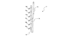
図2は、従来の冷媒分岐ユニットの概略正面図である。また、図3は、従来の冷媒分岐ユニットの概略斜視図である。また、図4は、従来の冷媒分岐ユニットに備えられている冷媒分配器の概略側面図である。また、図5は、従来の冷媒分岐ユニットに備えられている冷媒分配器の概略斜視図である。また、図6は、従来の冷媒分配器の概略上面図である。[Conventional refrigerant distributor]
Before describing the refrigerant distributor according to the first embodiment, a conventional refrigerant distributor will be described first.
FIG. 2 is a schematic front view of a conventional refrigerant branch unit. FIG. 3 is a schematic perspective view of a conventional refrigerant branch unit. FIG. 4 is a schematic side view of a refrigerant distributor provided in a conventional refrigerant branch unit. FIG. 5 is a schematic perspective view of a refrigerant distributor provided in a conventional refrigerant branch unit. FIG. 6 is a schematic top view of a conventional refrigerant distributor.
図2〜図6に示されるように、従来の冷媒分岐ユニット70は、液冷媒を分配する冷媒分配器71とガス冷媒を分岐するガス分岐ヘッダー72とを備えている。図4及び図5に示すように、冷媒分配器71は、冷媒を上から下に流通させる導入管73と、冷媒を下から上に流通させる導入管74とをU字状の導入管75を介して接続している。導入管74には、冷媒を各室内機に分配するための分岐管76a、分岐管76b、分岐管76c、分岐管76d、分岐管76e、分岐管76fが、それぞれ所定の間隔をあけて、冷媒の流通方向に沿って接続されている。なお、分岐管は、分岐管76aが最も低い位置に設けられ、分岐管76a、分岐管76b、分岐管76c、分岐管76d、分岐管76e、分岐管76fの順に高くなるように導入管74に設置されている。
As shown in FIGS. 2 to 6, the conventional
このように、従来の冷媒分配器71は、冷媒を導入管73の上から下へ流通させ、U字状の導入管75を経由し、下から上に向かって導入管74へ流入させる。導入管74へ流入した冷媒は、それぞれ分岐管76a、分岐管76b、分岐管76c、分岐管76d、分岐管76e、分岐管76fへ分岐して分配される。
As described above, the
図7は、従来の冷媒分配器において各分岐管へ分配される液冷媒の量を示す図である。ここで、分岐管76a、分岐管76b、分岐管76c、分岐管76d、分岐管76e、分岐管76fの各分岐管へ、どの程度均等に冷媒が分配されるかを解析したところ、図7に示される解析結果を得ることが出来た。図7に示されるように、分岐管76f、分岐管76e、分岐管76d、分岐管76c、分岐管76b、分岐管76aの順に液相冷媒が多く分配されている。すなわち導入管74の上方に設けられた分岐管ほど液相冷媒の量が多くなり、下方に設けられた分岐管には液相冷媒がほとんど分配されていない。
FIG. 7 is a diagram showing the amount of liquid refrigerant distributed to each branch pipe in the conventional refrigerant distributor. Here, when it was analyzed how evenly the refrigerant is distributed to the branch pipes of the
上方の分岐管に対して下方の分岐管の量が少なくなったのは、U字状の導入管75で発生した液相冷媒に対する遠心力が影響し、この遠心力によって、偏った液相冷媒が分岐管の入口を反れて流れたことが原因である。
The amount of the lower branch pipe relative to the upper branch pipe is reduced due to the centrifugal force to the liquid phase refrigerant generated in the
次に、分岐管を遠心方向、つまり液相冷媒が偏る方向に設置し、各分岐管に流入する液相冷媒の量を解析したところ、この場合も、導入管74の上方に設けられた分岐管ほど液相冷媒の量が多くなり、下方に設けられた分岐管には液相冷媒がほとんど分配されていない結果となった。これは、遠心力により、液相冷媒の流速が速くなり、液相冷媒の速度が速い状態で通過する下方の分岐管に冷媒が流入しにくくなったことが原因である。
Next, the branch pipes were installed in the centrifugal direction, that is, in the direction in which the liquid phase refrigerant is biased, and the amount of liquid phase refrigerant flowing into each branch pipe was analyzed. Also in this case, the branch provided above the
[冷媒分配器の構成]
次に、本実施の形態1に係る冷媒分配器について説明する。図8は、本発明の実施の形態1に係る冷媒分配器を搭載した冷媒分岐ユニットの概略斜視図である。また、図9は、本発明の実施の形態1に係る冷媒分配器の概略側面図である。また、図10は、本発明の実施の形態1に係る冷媒分配器の概略斜視図である。また、図11は、本発明の実施の形態1に係る冷媒分配器の概略上面図である。[Configuration of refrigerant distributor]
Next, the refrigerant distributor according to the first embodiment will be described. FIG. 8 is a schematic perspective view of a refrigerant branch unit equipped with the refrigerant distributor according to the first embodiment of the present invention. FIG. 9 is a schematic side view of the refrigerant distributor according to Embodiment 1 of the present invention. FIG. 10 is a schematic perspective view of a refrigerant distributor according to Embodiment 1 of the present invention. FIG. 11 is a schematic top view of the refrigerant distributor according to Embodiment 1 of the present invention.
図8〜図11に示されるように、冷媒分岐ユニット80は、液冷媒を分配する冷媒分配器20とガス冷媒を分岐するガス分岐ヘッダー35とを備えている。図9及び図10に示すように、冷媒分配器20は、冷媒を上から下に流通させる第一の導入管12と、冷媒を下から上に流通させる第二の導入管11とを、上面視した状態においてU字形状の調整管13を介して接続している。第一の導入管12は、水平で平坦な場所に鉛直方向に配置された場合において、上端部12aが開口し、下端部12bが閉口し、冷媒を上から下に流通させる。一方、第二の導入管11は、水平で平坦な場所に鉛直方向に配置された場合において、上流側である下端部11b及び下流側である上端部11aの両方が閉口し、冷媒を下から上に流通させる。なお、図中の矢印は冷媒の流れ15を示している。なお、上端部12aは本発明における「一方の端部」に相当する。また、下端部12bは本発明における「他方の端部」に相当する。
As shown in FIGS. 8 to 11, the
第二の導入管11及び第一の導入管12は、例えば外径が12.0(mm)で肉厚が0.7(mm)の配管である。また、調整管13は、例えば外径が9.52(mm)で肉厚が0.7(mm)で、上面視した状態においてU字形状の配管である。このように、調整管13の内径を、第二の導入管11及び第一の導入管12の内径より小さく設計することで、冷媒の循環量が少ないときでも、調整管13で冷媒の流速を十分に確保して、第二の導入管11への流入時に気液二相冷媒を十分に攪拌することができる。なお、本実施の形態1において、第二の導入管11、第一の導入管12及び調整管13の寸法について具体的な数値を例に示したが、本発明はこれに限定されず、空気調和機100の規模又は冷媒の種類等によって、適宜寸法を変更してもよい。
The
第二の導入管11には、冷媒を各室内機に分配するための分岐管10a、分岐管10b、分岐管10c、分岐管10d、分岐管10e、分岐管10fが、それぞれ所定の間隔をあけて冷媒の流通方向に沿って接続されている。なお、分岐管は、分岐管10aが最も低い位置に設けられ、分岐管10a、分岐管10b、分岐管10c、分岐管10d、分岐管10e、分岐管10fの順に高くなるように第二の導入管11に設置されている。なお、本実施の形態1において、第二の導入管11に分岐管10a〜10fの6本を接続した例を示したが、本発明はこれに限定されず、複数本の分岐管が第二の導入管11に接続されていればよい。このことは、後述する実施の形態2〜3についても同様である。また、分岐管10a〜10fのそれぞれを特に区別しない場合、分岐管10と称する。また、図8及び図11に示すように、分岐管10の下流側には室外膨張弁21が設けられている。
In the
[調整管の説明]
図12は、本発明の実施の形態1に係る冷媒分配器の下端部の拡大概略斜視図である。図12に示されるように、調整管13は接続部13aを介して第一の導入管12に接続されている。また、調整管13は接続部13bを介して第二の導入管11に接続されている。すなわち、調整管13は、第一の導入管12の下端部12b側を、第二の導入管11の上流側の下端部11bと第二の導入管11の最上流側に接続されている分岐管10aとの間に接続している。調整管13は、第二の導入管11及び第一の導入管12に対して、90°の角度で設置されている。[Description of adjusting pipe]
FIG. 12 is an enlarged schematic perspective view of the lower end portion of the refrigerant distributor according to the first embodiment of the present invention. As shown in FIG. 12, the
また、調整管13は、第二の導入管11に対して開口した接続部13bで気密に挿入され、第一の導入管12に対して開口した接続部13aで気密に挿入される。このため、調整管13の外径は、第二の導入管11及び第一の導入管12の外径より小さく設計する必要がある。また、調整管13は、下端部11b及び下端部12bから高さ25(mm)の位置に設置されている。なお、本実施の形態1において、調整管13が、下端部11b及び下端部12bから高さ25(mm)の位置に設置されている例を示したが、本発明はこれに限定されず、空気調和機100の規模又は冷媒の種類等によって、適宜高さを変更してもよい。また、図12において下端部11b及び下端部12bの高さが揃った例を示したが、下端部11b及び下端部12bの高さがそれぞれ異なってもよい。これらのことは、後述する実施の形態2〜3についても同様である。
Further, the
[冷媒分配器内での冷媒の挙動]
次に、冷媒分配器20内での冷媒の挙動について説明する。
図12に示されるように、第一の導入管12の上方から下方へ流入する気液二相の冷媒は、第一の導入管12の下端部12bの内壁面に衝突し、下方へ向かう勢いが打ち消されると共に、気相冷媒と液相冷媒が攪拌される。そして、気液二相の冷媒は、接続部13aから調整管13へ流入する。調整管13はU字形状をなしているため気液二相の冷媒には遠心力が加わる。接続部13bを介して調整管13を流出した気液二相の冷媒は、第二の導入管11に流入する。この際、気液二相の冷媒は、第二の導入管11の内壁面及び下端部11bの内壁面に衝突することで遠心力が打ち消されると共に流速が減速させられ、さらに衝突した際の衝撃で気液二相の冷媒の攪拌が一層促進される。攪拌が十分に行われ遠心力が打ち消された気液二相の冷媒は、第二の導入管11の上方に向かって流通し、各分岐管10に分配される。このように、気液二相の冷媒に加わる遠心力を打ち消し、冷媒の流速を減速させ、攪拌を十分に行った後に気液二相の冷媒を各分岐管10に分配することで、各分配器に均質な冷媒を供給することが可能となる。[The behavior of the refrigerant in the refrigerant distributor]
Next, the behavior of the refrigerant in the
As shown in FIG. 12, the gas-liquid two-phase refrigerant flowing downward from above the
図13は、本発明の実施の形態1に係る冷媒分配器において各分岐管へ分配される液冷媒の量を示す図である。図13に示されるように、各分岐管10a〜10fに分配される液相冷媒の量は、図7で示した液相冷媒の分配特性より改善され、各分岐管10a〜10fにほぼ均等に分配されている。このように、分岐管10a〜10fを備える第二の導入管11と、第一の導入管12とを調整管13で繋ぐことで、従来の冷媒分配器71の形状で発生していた遠心力による冷媒の偏りと、冷媒の流速の加速を第一の導入管12、第二の導入管11及び調整管13で打ち消すことが可能となる。
FIG. 13 is a diagram showing the amount of liquid refrigerant distributed to each branch pipe in the refrigerant distributor according to Embodiment 1 of the present invention. As shown in FIG. 13, the amount of liquid phase refrigerant distributed to each
[実施の形態1の効果]
以上のことから、本実施の形態1によれば、冷媒分配器20は、一方の端部が開口し他方の端部が閉口し、一方の端部から他方の端部の方向に冷媒を流通する第一の導入管12と、上流側及び下流側の両端部が閉口し、第一の導入管の冷媒の流通方向と逆方向に冷媒を流通する第二の導入管11と、第二の導入管11の冷媒の流通方向に接続された複数本の分岐管10と、第一の導入管12と第二の導入管11とを接続する調整管13と、を有し、調整管13は、第一の導入管12の他方の端部側を、第二の導入管11の上流側の端部と第二の導入管11の最上流側に接続されている分岐管10との間に接続している。このようにすることで、気液二相冷媒を複数の室内機40に均等に分配できる冷媒分配器20を得ることができる。[Effect of Embodiment 1]
From the above, according to the first embodiment, one end of the
また、第一の導入管12は、鉛直方向に配置された場合において、上方から下方へ冷媒を流通させ、第二の導入管11は、鉛直方向に配置された場合において、下方から上方へ冷媒を流通させる。このようにすることで、十分に気液二相冷媒を攪拌することができる冷媒分配器20を得ることができる。
When the
また、調整管13は、第一の導入管12及び前記第二の導入管11の内径よりも小さい径を有している。このようにすることで、冷媒の循環量が少ないときでも、調整管13で冷媒の流速を十分に確保して、第二の導入管11への流入時に気液二相冷媒を十分に攪拌することができる。
Further, the
また、調整管13は、上面視した状態においてU字形状である。このようにすることで、第一の導入管12から流出した冷媒を第二の導入管11の内壁面に衝突させることができ、冷媒に加わる遠心力及び流速の加速を打ち消すことができる冷媒分配器20を得ることができる。
Further, the
また、調整管13は、第一の導入管12及び第二の導入管11に対して垂直に設置されている。このようにすることで、第一の導入管12から流出した冷媒を第二の導入管11の内壁面に垂直に衝突させることができ、効率よく冷媒に加わる遠心力及び流速の加速を打ち消すことができる冷媒分配器20を得ることができる。
Further, the
また、圧縮機31、室外熱交換器33、複数の室外膨張弁21及び複数の室内熱交換器41を順に冷媒配管により接続して構成される冷凍サイクルを備えた空気調和機100であって、前記室外熱交換器33と前記複数の室外膨張弁21との間に、冷媒分配器20を備えるようにする。このようにすることで、気液二相冷媒を複数の室内機40に均等に分配できる冷媒分配器20を備えた空気調和機100を得ることができる。
Further, the
実施の形態2.
本実施の形態2における冷媒分配器の基本的な構成は実施の形態1における冷媒分配器と同様であるため、以下、実施の形態1との相違点を中心に本実施の形態2を説明する。実施の形態1と本実施の形態2との相違点は、調整管が第一の導入管及び第二の導入管に対して傾いている点である。Second Embodiment
The basic configuration of the refrigerant distributor according to the second embodiment is the same as that of the refrigerant distributor according to the first embodiment. Therefore, the second embodiment will be described below focusing on the differences with the first embodiment. . The difference between Embodiment 1 and Embodiment 2 is that the adjusting pipe is inclined with respect to the first introduction pipe and the second introduction pipe.
図14は、本発明の実施の形態2に係る冷媒分配器の下端部の拡大概略斜視図である。図14に示されるように、冷媒分配器20aは調整管17と、第一の導入管12と、第二の導入管11とを備えている。調整管17は上面視した状態においてU字形状をなしている。調整管17は、接続部13aを介して第一の導入管12に接続され、接続部13bを介して第二の導入管11に接続されている。第一の導入管12及び第二の導入管11が水平で平坦な場所で鉛直方向に配置された状態において、調整管17は、第一の導入管12及び第二の導入管11に対して、分岐管10側に傾いて接続されている。つまり、調整管17は上側に傾いて第一の導入管12及び第二の導入管11に接続されている。
FIG. 14 is an enlarged schematic perspective view of the lower end portion of the refrigerant distributor according to Embodiment 2 of the present invention. As shown in FIG. 14, the
[冷媒分配器内での冷媒の挙動]
次に、冷媒分配器20a内での冷媒の挙動について説明する。
図14に示されるように、第一の導入管12の上方から下方へ流入する気液二相の冷媒は、第一の導入管12の下端部12bの内壁面に衝突し、下方へ向かう勢いが打ち消されると共に、気相冷媒と液相冷媒が攪拌される。そして、気液二相の冷媒は、接続部13aから調整管17へ流入する。調整管17はU字形状をなしているため気液二相の冷媒には遠心力が加わる。接続部13bを介して調整管13を流出した気液二相の冷媒は、第二の導入管11に流入する。この際、気液二相の冷媒は、第二の導入管11の内壁面及び下端部11bの内壁面に衝突することで遠心力が打ち消されると共に流速が減速させられ、さらに衝突した際の衝撃で気液二相の冷媒の攪拌が一層促進される。攪拌が十分に行われ遠心力が打ち消された気液二相の冷媒は、第二の導入管11の上方に向かって流通し、各分岐管10に分配される。このように、気液二相の冷媒に加わる遠心力を打ち消すと共に流速を減速させ、さらに攪拌を十分に行った後に気液二相の冷媒を各分岐管10に分配することで、各分配器に均質な冷媒を供給することが可能となる。[The behavior of the refrigerant in the refrigerant distributor]
Next, the behavior of the refrigerant in the
As shown in FIG. 14, the gas-liquid two-phase refrigerant flowing downward from above the
[実施の形態2の効果]
以上のことから、本実施の形態2によれば、調整管17は、分岐管10側に傾いて設けられている。このようにすることで、実施の形態1の効果に加えて、気液二相の冷媒に加わる遠心力を打ち消すと共に流速を減速させ、さらに攪拌を十分に行った後に気液二相の冷媒を各分岐管10に分配することで、各分配器に均質な冷媒を供給することが可能となる。[Effect of Embodiment 2]
From the above, according to the second embodiment, the
実施の形態3.
本実施の形態3における冷媒分配器の基本的な構成は実施の形態1における冷媒分配器と同様であるため、以下、実施の形態1との相違点を中心に本実施の形態3を説明する。実施の形態1と本実施の形態3との相違点は、調整管が直線形状である点である。Third Embodiment
The basic configuration of the refrigerant distributor according to the third embodiment is the same as that of the refrigerant distributor according to the first embodiment. Therefore, the third embodiment will be described below focusing on the differences with the first embodiment. . The difference between Embodiment 1 and
図15は、本発明の実施の形態3に係る冷媒分配器の下端部の拡大概略斜視図である。図15に示されるように、冷媒分配器20bは調整管16と、第一の導入管12と、第二の導入管11とを備えている。調整管16は上面視した状態において直線形状をなしている。調整管16は、接続部13aを介して第一の導入管12に接続され、接続部13bを介して第二の導入管11に接続されている。第一の導入管12及び第二の導入管11が水平で平坦な場所で鉛直方向に配置された状態において、調整管16は、第一の導入管12及び第二の導入管11に水平方向に接続されている。なお、本実施の形態3において、調整管16が水平方向に接続された例を示したが本発明はこれに限定されない。例えば、第一の導入管12の接続部13aを、第二の導入管11の接続部13bより高い位置に設け、調整管16を傾けて設置してもよい。この場合、調整管16から流出した冷媒が第二の導入管11の下端部11bにより多く衝突することで、一層、気液二相の冷媒が攪拌されると共に、冷媒の流速を減速させる効果を得ることができる。
FIG. 15 is an enlarged schematic perspective view of the lower end portion of the refrigerant distributor according to
[冷媒分配器内での冷媒の挙動]
次に、冷媒分配器20b内での冷媒の挙動について説明する。
図15に示されるように、第一の導入管12の上方から下方へ流入する気液二相の冷媒は、第一の導入管12の下端部12bの内壁面に衝突し、下方へ向かう勢いが打ち消されると共に、気相冷媒と液相冷媒が攪拌される。そして、気液二相の冷媒は、接続部13aから調整管16へ流入する。接続部13bを介して調整管16を流出した気液二相の冷媒は、第二の導入管11に流入する。この際、気液二相の冷媒は、第二の導入管11の内壁面及び下端部11bに衝突することで流速が減速させられ、さらに衝突した際の衝撃で気液二相の冷媒の攪拌が一層促進される。攪拌が十分に行われた気液二相の冷媒は、第二の導入管11の上方に向かって流通し、各分岐管10に分配される。このように、気液二相の冷媒の流速を減速させ、攪拌を十分に行った後に気液二相の冷媒を各分岐管10に分配することで、各分配器に均質な冷媒を供給することが可能となる。[The behavior of the refrigerant in the refrigerant distributor]
Next, the behavior of the refrigerant in the
As shown in FIG. 15, the gas-liquid two-phase refrigerant flowing downward from above the
[実施の形態3の効果]
以上のことから、本実施の形態3によれば、調整管16は、上面視した状態において直線形状である。このようにすることで、実施の形態1の効果に加えて、冷媒の流速を減速させ、尚且つ気液二相の冷媒の攪拌を促進することができる冷媒分配器20bを得ることができる。[Effect of Third Embodiment]
From the above, according to the third embodiment, the
また、調整管16は、第一の導入管12側の接続部13aが第二の導入管11側の接続部13bより高い位置に接続されている。このようにすることで、調整管16から流出した冷媒が第二の導入管11の下端部11bにより多く衝突することで、一層、気液二相の冷媒が攪拌されると共に、冷媒の流速を減速させる効果を得ることができる。
Further, the
以上、実施の形態1〜3について説明したが、本発明は各実施の形態の説明に限定されない。例えば、各実施の形態の全て又は一部を組み合わせることも可能である。 The first to third embodiments have been described above, but the present invention is not limited to the description of the respective embodiments. For example, it is also possible to combine all or part of each embodiment.
10 分岐管、10a〜10f 分岐管、11 第二の導入管、11a 上端部、11b 下端部、12 第一の導入管、12a 上端部、12b 下端部、13 調整管、13a 接続部、13b 接続部、15 冷媒の流れ、16 調整管、17 調整管、20冷媒分配器、20a 冷媒分配器、20b 冷媒分配器、21 室外膨張弁、21a〜21f 室外膨張弁、30 室外機、31 圧縮機、32 四方弁、33 室外熱交換器、34 室外ファン、35 ガス分岐ヘッダー、40 室内機、40a〜40f 室内機、41 室内熱交換器、41a〜41f 室内熱交換器、70 冷媒分岐ユニット、71 冷媒分配器、72 ガス分岐ヘッダー、73 導入管、74 導入管、75 導入管、76 分岐管、76a〜76f 分岐管、80 冷媒分岐ユニット、100 空気調和機。
Claims (8)
上流側及び下流側の両端部が閉口し、前記第一の導入管の冷媒の流通方向と逆方向に冷媒を流通する第二の導入管と、
前記第二の導入管の冷媒の流通方向に沿って順に接続された複数本の分岐管と、
前記第一の導入管と前記第二の導入管とを接続する調整管と、を有し、
前記調整管は、
前記第一の導入管の前記他方の端部側を、前記第二の導入管の上流側の端部と前記第二の導入管の最上流側に接続されている前記分岐管との間に接続し、
上面視した状態においてU字形状である
冷媒分配器。 A first inlet pipe which is open at one end and closed at the other end, and which circulates the refrigerant in the direction from one end to the other end;
A second introduction pipe which is closed at both ends on the upstream side and the downstream side and which circulates the refrigerant in a direction opposite to the circulation direction of the refrigerant in the first introduction pipe;
A plurality of branch pipes connected in order along the flow direction of the refrigerant in the second introduction pipe;
An adjusting pipe connecting the first introduction pipe and the second introduction pipe;
The adjustment pipe is
Between the other end of the first inlet pipe and the upstream end of the second inlet pipe and the branch pipe connected to the most upstream side of the second inlet pipe connect,
A refrigerant distributor that is U-shaped in a top view .
上流側及び下流側の両端部が閉口し、前記第一の導入管の冷媒の流通方向と逆方向に冷媒を流通する第二の導入管と、
前記第二の導入管の冷媒の流通方向に沿って順に接続された複数本の分岐管と、
前記第一の導入管と前記第二の導入管とを接続する調整管と、を有し、
前記調整管は、
前記第一の導入管の前記他方の端部側を、前記第二の導入管の上流側の端部と前記第二の導入管の最上流側に接続されている前記分岐管との間に接続し、
上面視した状態において直線形状であり、
前記第一の導入管側の接続部が前記第二の導入管側の接続部より高い位置に接続されている
冷媒分配器。 A first inlet pipe which is open at one end and closed at the other end, and which circulates the refrigerant in the direction from one end to the other end;
A second introduction pipe which is closed at both ends on the upstream side and the downstream side and which circulates the refrigerant in a direction opposite to the circulation direction of the refrigerant in the first introduction pipe;
A plurality of branch pipes connected in order along the flow direction of the refrigerant in the second introduction pipe;
An adjusting pipe connecting the first introduction pipe and the second introduction pipe;
The adjustment pipe is
Between the other end of the first inlet pipe and the upstream end of the second inlet pipe and the branch pipe connected to the most upstream side of the second inlet pipe connect,
It has a linear shape when viewed from above,
The refrigerant distributor in which the connection on the first introduction pipe side is connected to a position higher than the connection on the second introduction pipe side .
鉛直方向に配置された場合において、上方から下方へ冷媒を流通させ、
前記第二の導入管は、
鉛直方向に配置された場合において、下方から上方へ冷媒を流通させる
請求項1又は2に記載の冷媒分配器。 The first introduction pipe is
In the case of being arranged in the vertical direction, the refrigerant is allowed to flow downward from above,
The second introduction pipe is
The refrigerant distributor according to claim 1 or 2 , wherein the refrigerant is made to flow upward from below when it is arranged in the vertical direction.
前記第一の導入管及び前記第二の導入管の内径よりも小さい径を有している
請求項1〜3の何れか一項に記載の冷媒分配器。 The adjustment pipe is
The refrigerant distributor according to any one of claims 1 to 3, which has a diameter smaller than the inner diameter of the first introduction pipe and the second introduction pipe.
前記第一の導入管及び前記第二の導入管に対して垂直に設置されている
請求項1及び請求項1に従属する請求項3〜4の何れか一項に記載の冷媒分配器。 The adjustment pipe is
The refrigerant distributor according to any one of claims 3 to 4, which is installed vertically to the first introduction pipe and the second introduction pipe.
前記分岐管側に傾いている
請求項1及び請求項1に従属する請求項3〜4の何れか一項に記載の冷媒分配器。 The adjustment pipe is
The refrigerant distributor according to any one of claims 3 to 4, which is inclined toward the branch pipe side.
前記凝縮器と前記複数の室外膨張弁との間に、請求項1〜6の何れか一項に記載の冷媒分配器を備えた空気調和機。 An air conditioner comprising a refrigeration cycle configured by connecting a compressor, a condenser, a plurality of outdoor expansion valves, and a plurality of evaporators in order by a refrigerant pipe,
The air conditioner provided with the refrigerant distributor as described in any one of Claims 1-6 between the said condenser and these outdoor expansion valves.
請求項7に記載の空気調和機。 The air conditioner according to claim 7 , wherein the compressor, the condenser, the plurality of outdoor expansion valves, and the refrigerant distributor are mounted on a single outdoor unit.
Applications Claiming Priority (1)
| Application Number | Priority Date | Filing Date | Title |
|---|---|---|---|
| PCT/JP2015/080113 WO2017072833A1 (en) | 2015-10-26 | 2015-10-26 | Refrigerant distributor, and air conditioner using same |
Publications (2)
| Publication Number | Publication Date |
|---|---|
| JPWO2017072833A1 JPWO2017072833A1 (en) | 2018-06-07 |
| JP6425830B2 true JP6425830B2 (en) | 2018-11-21 |
Family
ID=58629909
Family Applications (1)
| Application Number | Title | Priority Date | Filing Date |
|---|---|---|---|
| JP2017547211A Expired - Fee Related JP6425830B2 (en) | 2015-10-26 | 2015-10-26 | Refrigerant distributor and air conditioner using the same |
Country Status (5)
| Country | Link |
|---|---|
| US (1) | US10712062B2 (en) |
| EP (1) | EP3370020B1 (en) |
| JP (1) | JP6425830B2 (en) |
| CN (1) | CN108351133B (en) |
| WO (1) | WO2017072833A1 (en) |
Families Citing this family (5)
| Publication number | Priority date | Publication date | Assignee | Title |
|---|---|---|---|---|
| US20220042727A1 (en) * | 2019-09-13 | 2022-02-10 | Carrier Corporation | Hvac unit with expansion device |
| WO2022038708A1 (en) * | 2020-08-19 | 2022-02-24 | 三菱電機株式会社 | Air conditioner |
| SE2030317A1 (en) * | 2020-10-22 | 2022-04-23 | Wedholms Ab | Procedure and arrangement for heat exchange |
| FR3131771B1 (en) * | 2022-01-13 | 2024-04-12 | Valeo Systemes Thermiques | Thermal conditioning system |
| DE102023200844A1 (en) | 2023-02-02 | 2024-08-08 | Robert Bosch Gesellschaft mit beschränkter Haftung | Combined heat and power device and building heat pump, air conditioning system, household refrigeration appliance with a combined heat and power device and method for operating a combined heat and power device |
Family Cites Families (25)
| Publication number | Priority date | Publication date | Assignee | Title |
|---|---|---|---|---|
| JPH02219966A (en) * | 1989-02-21 | 1990-09-03 | Matsushita Refrig Co Ltd | Refrigerant flow divider |
| KR950002921Y1 (en) * | 1991-01-30 | 1995-04-17 | 삼성전자 주식회사 | Controlling circuit of multi-air conditioner |
| JPH06221720A (en) | 1993-01-29 | 1994-08-12 | Sanyo Electric Co Ltd | Heat exchanger |
| JPH08247581A (en) * | 1995-03-15 | 1996-09-27 | Hitachi Ltd | Distributor |
| JP2003121029A (en) * | 2001-10-12 | 2003-04-23 | Mitsubishi Heavy Ind Ltd | Refrigerant distributor and air conditioner with refrigerant distributor |
| US6606882B1 (en) * | 2002-10-23 | 2003-08-19 | Carrier Corporation | Falling film evaporator with a two-phase flow distributor |
| US6688137B1 (en) * | 2002-10-23 | 2004-02-10 | Carrier Corporation | Plate heat exchanger with a two-phase flow distributor |
| US7044200B2 (en) * | 2004-02-26 | 2006-05-16 | Carrier Corporation | Two-phase refrigerant distribution system for multiple pass evaporator coils |
| US20050262872A1 (en) * | 2004-05-26 | 2005-12-01 | Carrier Corporation | Two-phase refrigerant distribution system for parallel tube evaporator coils |
| US7735333B2 (en) * | 2005-07-01 | 2010-06-15 | Ming-Li Tso | Thermal compensation system and device there of in heat pump and refrigeration system |
| JP2007139231A (en) * | 2005-11-15 | 2007-06-07 | Hitachi Ltd | Refrigerator distributor and air conditioner using it |
| US20100314090A1 (en) * | 2006-02-15 | 2010-12-16 | Gac Corporation | Heat exchanger |
| DE102006055837A1 (en) | 2006-11-10 | 2008-05-15 | Visteon Global Technologies Inc., Van Buren | Heat exchanger i.e. evaporator, for vehicle air conditioning system, has two heat exchanger registers with respective ports that are arranged diagonally and third heat exchanger register with third port that is arranged on same side |
| JP4887213B2 (en) * | 2007-05-18 | 2012-02-29 | 日立アプライアンス株式会社 | Refrigerant distributor and air conditioner |
| CN102203524B (en) * | 2008-09-05 | 2014-03-19 | 丹佛斯公司 | An expansion valve with force equalization |
| JP5474403B2 (en) * | 2009-05-20 | 2014-04-16 | 三洋電機株式会社 | Refrigerant shunt |
| JP5020298B2 (en) * | 2009-10-15 | 2012-09-05 | 三菱電機株式会社 | Refrigerant distributor and heat pump device using the refrigerant distributor |
| US20110259551A1 (en) * | 2010-04-23 | 2011-10-27 | Kazushige Kasai | Flow distributor and environmental control system provided the same |
| EP2392881B1 (en) * | 2010-06-04 | 2013-01-02 | Thermofin GmbH | Heat exchanger for phase converting coolant with horizontal distribution and collection pipe |
| JP5562879B2 (en) * | 2011-02-01 | 2014-07-30 | 日立アプライアンス株式会社 | Refrigerant distributor and refrigeration cycle apparatus including the same |
| JP2012172862A (en) | 2011-02-18 | 2012-09-10 | Mitsubishi Electric Corp | Multi-chamber air conditioner |
| JP5436531B2 (en) * | 2011-12-28 | 2014-03-05 | 三菱電機株式会社 | Heat pump equipment |
| JP2013148309A (en) * | 2012-01-23 | 2013-08-01 | Hitachi Appliances Inc | Coolant distributor and refrigeration cycle device including the same |
| US20140123696A1 (en) * | 2012-11-02 | 2014-05-08 | Hongseong KIM | Air conditioner and evaporator inlet header distributor therefor |
| JP6446990B2 (en) * | 2014-10-16 | 2019-01-09 | ダイキン工業株式会社 | Refrigerant shunt |
-
2015
- 2015-10-26 US US15/763,145 patent/US10712062B2/en active Active
- 2015-10-26 WO PCT/JP2015/080113 patent/WO2017072833A1/en active Application Filing
- 2015-10-26 JP JP2017547211A patent/JP6425830B2/en not_active Expired - Fee Related
- 2015-10-26 EP EP15907197.6A patent/EP3370020B1/en active Active
- 2015-10-26 CN CN201580084141.9A patent/CN108351133B/en active Active
Also Published As
| Publication number | Publication date |
|---|---|
| CN108351133B (en) | 2020-05-19 |
| US10712062B2 (en) | 2020-07-14 |
| CN108351133A (en) | 2018-07-31 |
| EP3370020A1 (en) | 2018-09-05 |
| EP3370020B1 (en) | 2020-07-01 |
| US20190056158A1 (en) | 2019-02-21 |
| EP3370020A4 (en) | 2019-06-19 |
| WO2017072833A1 (en) | 2017-05-04 |
| JPWO2017072833A1 (en) | 2018-06-07 |
Similar Documents
| Publication | Publication Date | Title |
|---|---|---|
| JP6425830B2 (en) | Refrigerant distributor and air conditioner using the same | |
| EP3009771B1 (en) | Air-conditioning device | |
| US11365912B2 (en) | Suction duct and multiple suction ducts inside a shell of a flooded evaporator | |
| EP3370000A1 (en) | Outdoor unit and indoor unit for air conditioner | |
| US10054377B2 (en) | Air conditioner | |
| EP2184564A2 (en) | Distributor and refrigerant circulation system comprising the same | |
| US11333401B2 (en) | Refrigeration cycle apparatus | |
| US20160040896A1 (en) | Air conditioner | |
| JP2007139231A (en) | Refrigerator distributor and air conditioner using it | |
| US9234673B2 (en) | Heat exchanger with subcooling circuit | |
| JP6329786B2 (en) | Air conditioner heat exchanger | |
| JP2011127831A (en) | Heat exchanger and refrigerating cycle device including the same | |
| JP2018119743A (en) | Heat exchanger and air conditioner | |
| JP5957535B2 (en) | Parallel flow heat exchanger and air conditioner using the same | |
| JP2018194251A (en) | Heat exchanger | |
| CN113217996A (en) | Microchannel heat exchanger and air conditioner | |
| EP3521747B1 (en) | Heat exchanger and air conditioner | |
| JP2012026615A (en) | Outdoor unit, and refrigeration cycle apparatus with the same | |
| JP5525278B2 (en) | Heat source unit | |
| EP3647711A1 (en) | Heat exchanger | |
| CN109073334B (en) | Heat exchanger and air conditioner | |
| JP6664172B2 (en) | Heat exchanger and air conditioner using the same | |
| KR102169284B1 (en) | Heat exchanger and air conditional having the same | |
| JP2020115045A (en) | Air conditioner | |
| CN111587350B (en) | Heat exchanger, outdoor unit, and refrigeration cycle device |
Legal Events
| Date | Code | Title | Description |
|---|---|---|---|
| A521 | Request for written amendment filed |
Free format text: JAPANESE INTERMEDIATE CODE: A523 Effective date: 20180118 |
|
| A621 | Written request for application examination |
Free format text: JAPANESE INTERMEDIATE CODE: A621 Effective date: 20180118 |
|
| TRDD | Decision of grant or rejection written | ||
| A01 | Written decision to grant a patent or to grant a registration (utility model) |
Free format text: JAPANESE INTERMEDIATE CODE: A01 Effective date: 20180925 |
|
| A61 | First payment of annual fees (during grant procedure) |
Free format text: JAPANESE INTERMEDIATE CODE: A61 Effective date: 20181023 |
|
| R150 | Certificate of patent or registration of utility model |
Ref document number: 6425830 Country of ref document: JP Free format text: JAPANESE INTERMEDIATE CODE: R150 |
|
| LAPS | Cancellation because of no payment of annual fees |