JP6418786B2 - Pattern creating method, program, and information processing apparatus - Google Patents
Pattern creating method, program, and information processing apparatus Download PDFInfo
- Publication number
- JP6418786B2 JP6418786B2 JP2014107477A JP2014107477A JP6418786B2 JP 6418786 B2 JP6418786 B2 JP 6418786B2 JP 2014107477 A JP2014107477 A JP 2014107477A JP 2014107477 A JP2014107477 A JP 2014107477A JP 6418786 B2 JP6418786 B2 JP 6418786B2
- Authority
- JP
- Japan
- Prior art keywords
- pattern
- cell
- mask
- line
- cells
- Prior art date
- Legal status (The legal status is an assumption and is not a legal conclusion. Google has not performed a legal analysis and makes no representation as to the accuracy of the status listed.)
- Active
Links
Images


Classifications
-
- G—PHYSICS
- G03—PHOTOGRAPHY; CINEMATOGRAPHY; ANALOGOUS TECHNIQUES USING WAVES OTHER THAN OPTICAL WAVES; ELECTROGRAPHY; HOLOGRAPHY
- G03F—PHOTOMECHANICAL PRODUCTION OF TEXTURED OR PATTERNED SURFACES, e.g. FOR PRINTING, FOR PROCESSING OF SEMICONDUCTOR DEVICES; MATERIALS THEREFOR; ORIGINALS THEREFOR; APPARATUS SPECIALLY ADAPTED THEREFOR
- G03F1/00—Originals for photomechanical production of textured or patterned surfaces, e.g., masks, photo-masks, reticles; Mask blanks or pellicles therefor; Containers specially adapted therefor; Preparation thereof
- G03F1/36—Masks having proximity correction features; Preparation thereof, e.g. optical proximity correction [OPC] design processes
-
- G—PHYSICS
- G03—PHOTOGRAPHY; CINEMATOGRAPHY; ANALOGOUS TECHNIQUES USING WAVES OTHER THAN OPTICAL WAVES; ELECTROGRAPHY; HOLOGRAPHY
- G03F—PHOTOMECHANICAL PRODUCTION OF TEXTURED OR PATTERNED SURFACES, e.g. FOR PRINTING, FOR PROCESSING OF SEMICONDUCTOR DEVICES; MATERIALS THEREFOR; ORIGINALS THEREFOR; APPARATUS SPECIALLY ADAPTED THEREFOR
- G03F7/00—Photomechanical, e.g. photolithographic, production of textured or patterned surfaces, e.g. printing surfaces; Materials therefor, e.g. comprising photoresists; Apparatus specially adapted therefor
- G03F7/70—Microphotolithographic exposure; Apparatus therefor
- G03F7/70216—Mask projection systems
- G03F7/70283—Mask effects on the imaging process
-
- G—PHYSICS
- G03—PHOTOGRAPHY; CINEMATOGRAPHY; ANALOGOUS TECHNIQUES USING WAVES OTHER THAN OPTICAL WAVES; ELECTROGRAPHY; HOLOGRAPHY
- G03F—PHOTOMECHANICAL PRODUCTION OF TEXTURED OR PATTERNED SURFACES, e.g. FOR PRINTING, FOR PROCESSING OF SEMICONDUCTOR DEVICES; MATERIALS THEREFOR; ORIGINALS THEREFOR; APPARATUS SPECIALLY ADAPTED THEREFOR
- G03F7/00—Photomechanical, e.g. photolithographic, production of textured or patterned surfaces, e.g. printing surfaces; Materials therefor, e.g. comprising photoresists; Apparatus specially adapted therefor
- G03F7/70—Microphotolithographic exposure; Apparatus therefor
- G03F7/70425—Imaging strategies, e.g. for increasing throughput or resolution, printing product fields larger than the image field or compensating lithography- or non-lithography errors, e.g. proximity correction, mix-and-match, stitching or double patterning
- G03F7/70433—Layout for increasing efficiency or for compensating imaging errors, e.g. layout of exposure fields for reducing focus errors; Use of mask features for increasing efficiency or for compensating imaging errors
- G03F7/70441—Optical proximity correction [OPC]
Description
本発明は、パターンの作成方法、プログラムおよび情報処理装置に関する。 The present invention relates to a pattern creation method, a program, and an information processing apparatus.
リソグラフィ技術において、光源からの光を用いてマスクを照明する照明光学系と、マスクのパターンの像を基板(ウエハ等)に投影する投影光学系を有する露光装置が用いられている。 In lithography technology, an exposure apparatus having an illumination optical system that illuminates a mask using light from a light source and a projection optical system that projects an image of a mask pattern onto a substrate (wafer or the like) is used.
基板に形成すべき目標パターンの最小寸法が、露光に使用される光源の波長以下になると、マスクパターンの像を基板上に投影する際に、意図しない光の相互作用が隣接するパターン間に起きる。そのため、マスクの各パターンからの光が相互作用して干渉縞が発生し、目標のパターンと異なった形状の、意図しない像が基板上に形成される。目標パターンの最小寸法と光源の波長との差が大きくなるに従って、パターンの解像不良が起きやすくなる。 When the minimum dimension of the target pattern to be formed on the substrate is less than or equal to the wavelength of the light source used for exposure, an unintended light interaction occurs between adjacent patterns when an image of the mask pattern is projected onto the substrate. . Therefore, light from each pattern of the mask interacts to generate interference fringes, and an unintended image having a shape different from the target pattern is formed on the substrate. As the difference between the minimum dimension of the target pattern and the wavelength of the light source increases, pattern resolution failure tends to occur.
コンピュータを用いてマスクパターンを作成する方法として、多数のスタンダードセルを含むセルライブラリから複数のセルを選択して配置し、配置した複数セルのパターンに光近接効果補正を行う方法が知られている。光近接効果補正(OPC:Optical Proximity Correction)では、近接する各パターンからの光が相互作用してパターンの像の形成に及ぼす影響を考慮して、パターンの像が目標範囲に収まるようにパターンの構成要素である各パターン要素の形状を変更する補正を行う。セルライブラリには、マスクのパターンとして使用される基本的なパターンの構成であるセルが複数含まれており、複数のセルは互いに異なるパターンを有する。 As a method of creating a mask pattern using a computer, there is known a method of selecting and arranging a plurality of cells from a cell library including a large number of standard cells and correcting the optical proximity effect on the arranged pattern of the plurality of cells. . In the optical proximity correction (OPC), the light of each adjacent pattern interacts to influence the influence on the formation of the pattern image, so that the pattern image is within the target range. Correction for changing the shape of each pattern element which is a constituent element is performed. The cell library includes a plurality of cells having a basic pattern configuration used as a mask pattern, and the plurality of cells have different patterns.
しかし、使用する複数のセルを全て配置してマスクのパターンを作成した後に、マスクパターン全体(フルチップ)でOPCを行うと、パターン要素の形状を変更するための計算がパターン要素の数の多さに応じて増えるため、OPCの計算量が非常に多いという問題があった。そのため、特許文献1では、各セルのパターンに予め個別にOPCをかけてパターンの形状を補正し、OPC済みの複数のセルを配置してマスクパターンを構成し、その後、マスクパターン全体に対して仕上げのOPCをかけるという方法が提案されている。こうすることにより、マスクパターン全体のOPCにおいて、各セルのパターンが既にOPCを行われている分、一部のパターン要素について既にその像が目標範囲に収まっていればOPCの必要がなくなり、補正すべきパターン要素の数が減り、結果としてOPCの計算量を減らすことができる。 However, if a mask pattern is created by arranging all of the cells to be used and then OPC is performed on the entire mask pattern (full chip), the calculation for changing the shape of the pattern element requires a large number of pattern elements. Therefore, there is a problem that the amount of calculation of OPC is very large. Therefore, in Patent Document 1, the pattern of each cell is individually subjected to OPC in advance to correct the shape of the pattern, and a plurality of OPC-completed cells are arranged to form a mask pattern. A method of applying finishing OPC has been proposed. By doing this, in the OPC of the entire mask pattern, since the pattern of each cell has already been subjected to OPC, if the image of some pattern elements is already within the target range, OPC is not necessary, and correction is performed. The number of pattern elements to be reduced is reduced, and as a result, the amount of calculation of OPC can be reduced.
しかし、特許文献1に記載の方法でも、なお、マスクのパターン全体で行うOPC処理の計算量はまだ多く、計算量のさらなる低減が求められている。 However, even in the method described in Patent Document 1, the amount of calculation of the OPC process performed on the entire mask pattern is still large, and further reduction of the amount of calculation is required.
そこで、本発明は、パターンの光近接効果補正に要する計算量を減らすことを目的とする。 Accordingly, an object of the present invention is to reduce the amount of calculation required for correcting the optical proximity effect of a pattern.
上記課題を解決する本発明の一側面としての作成方法は、マスクのパターンを作成する作成方法において、複数のセルを含むセルライブラリからセルを選択する工程と、選択されたセル内に、選択されたセルの第1パターンとは異なる第2パターンを前記第1パターンに接するように追加して配置し、前記第1パターンと前記第2パターンを含むライン状のパターンを形成する配置工程と、前記第1パターンと前記第2パターンを含むライン状のパターンを含む前記選択されたセルのパターンに対して第1光近接効果補正を行う工程と、
前記第1光近接効果補正がなされた前記第1パターンと前記第2パターンを含むライン状のパターンを含む前記選択されたセルとその他のセルが近接して配置された複数のセルのパターンに対して第2光近接効果補正を行う工程と、前記第2光近接効果補正がなされた前記複数のセルのパターンを含むマスクのパターンを作成する作成工程とを情報処理装置が行い、作成されたマスクのパターンにおける前記第1パターンと前記第2パターンを含むライン状のパターンは、基板上に形成された1方向に延びるラインパターン上に解像され、解像された前記第1パターンと前記第2パターンを含むライン状のパターンによって前記ラインパターンをカットするためのパターンであり、前記配置工程において、前記基板上に形成された前記カットされたラインパターンを含むデバイスの作動に影響を及ぼさない位置に前記第2パターンを配置することを特徴とする。
A creation method according to one aspect of the present invention for solving the above-described problem is a creation method for creating a mask pattern, wherein a cell is selected from a cell library including a plurality of cells, and the selected cell is selected. A second pattern different from the first pattern of the cells is additionally arranged so as to be in contact with the first pattern, and an arrangement step of forming a linear pattern including the first pattern and the second pattern; Performing a first optical proximity effect correction on the pattern of the selected cell including a linear pattern including the first pattern and the second pattern;
For the pattern of a plurality of cells in which the selected cell including the line pattern including the first pattern and the second pattern subjected to the first optical proximity effect correction and the other cells are arranged close to each other The information processing apparatus performs a second optical proximity effect correction step and a creation step of creating a mask pattern including the plurality of cell patterns subjected to the second optical proximity effect correction. A line-shaped pattern including the first pattern and the second pattern is resolved on a line pattern extending in one direction formed on the substrate, and the resolved first pattern and second Ri pattern der for cutting the line pattern by a line-shaped pattern including a pattern, in the disposing step, the cut formed on the substrate Wherein the placement of the second pattern in a position that does not affect the operation of the device containing the line pattern.
本発明によれば、パターンの光近接効果補正に要する計算量を減らすことができる。 According to the present invention, the amount of calculation required for correcting the optical proximity effect of a pattern can be reduced.
以下に、本発明の好ましい実施形態を添付の図面に基づいて詳細に説明する。 Hereinafter, preferred embodiments of the present invention will be described in detail with reference to the accompanying drawings.
(実施形態1)
本実施形態は、半導体デバイスを作製するためのリソグラフィ技術に関し、マスクを照明する照明光学系とマスクのパターンの像を基板に投影する投影光学系とにより基板を露光する露光装置に用いられるマスクのパターンのデータ作成に関する。
(Embodiment 1)
The present embodiment relates to a lithography technique for manufacturing a semiconductor device, and relates to a mask used in an exposure apparatus that exposes a substrate by an illumination optical system that illuminates the mask and a projection optical system that projects an image of the mask pattern onto the substrate. It relates to pattern data creation.
当該マスクのパターンのデータ作成は、コンピュータの処理部(CPU、MPU、DSP、FPGA等)がプログラムを読み出して実行され、コンピュータがパターンのデータを用いて計算することにより行われる。本実施形態の機能を実現するソフトウェアやプログラムはネットワーク又は各種記憶媒体を介して1つ又は複数のコンピュータよりなる情報処理装置に供給される。その情報処理装置の処理部が、記録媒体または記憶媒体に記録または記憶されたプログラムを読み出すことにより、プログラムが実行される。離れた位置にある複数のコンピュータが有線又は無線通信で互いにデータを送受信することにより、プログラムの各種処理を行っても良い。情報処理装置の処理部は、後述する各ステップを実行する各手段を構成する。 The mask pattern data is created by a computer processing unit (CPU, MPU, DSP, FPGA, etc.) reading out and executing a program, and the computer calculating using the pattern data. Software and programs that implement the functions of the present embodiment are supplied to an information processing apparatus including one or more computers via a network or various storage media. The processing unit of the information processing apparatus reads the program recorded or stored in the recording medium or the storage medium, so that the program is executed. A plurality of computers at distant positions may perform various processes of the program by transmitting and receiving data to and from each other by wired or wireless communication. The processing unit of the information processing apparatus constitutes each means for executing each step described later.
情報処理装置(コンピュータ)は、多数のセルを含むセルライブラリから複数のセルを選択し、選択された複数のセルを配置してマスクパターンのレイアウト(チップレイアウト)を決定して、配置されたセルのパターンに対して光近接効果補正を行う。これにより、基板(ウエハなど)上に形成すべき目標パターンに対応するマスクのパターンを作成する。 The information processing apparatus (computer) selects a plurality of cells from a cell library including a large number of cells, arranges the selected cells, determines a mask pattern layout (chip layout), and arranges the cells. The optical proximity effect correction is performed on the pattern. Thus, a mask pattern corresponding to a target pattern to be formed on a substrate (wafer or the like) is created.
まず、コンピュータは、複数のセルを含むセルライブラリから選択されたセルのデータを取得する。そして、選択されたセルの第1パターンに第2パターンを追加して配置する。次に、第1パターンと第2パターンを含むパターンに対して光近接効果補正を行う。次に、光近接効果補正がなされた第1パターンと第2パターンのセルを含む複数のセルのパターンを用いてマスクのパターンを作成する。作成されたマスクのパターンに対して更に光近接効果補正を行う。 First, the computer acquires data of a selected cell from a cell library including a plurality of cells. Then, the second pattern is added to the first pattern of the selected cell and arranged. Next, optical proximity effect correction is performed on the pattern including the first pattern and the second pattern. Next, a mask pattern is created using a plurality of cell patterns including the first pattern cell and the second pattern cell subjected to the optical proximity correction. Optical proximity effect correction is further performed on the created mask pattern.
以下、コンピュータが行うマスクパターンの作成方法をより詳細に説明する。図1に、コンピュータが行うマスクパターンの作成方法のフローチャートを示す。 Hereinafter, a mask pattern creation method performed by a computer will be described in more detail. FIG. 1 shows a flowchart of a mask pattern creation method performed by a computer.
ステップS102では、コンピュータの処理部が、複数種類のスタンダードセルを含むセルライブラリから、マスクのパターンの作成に使用するためのセルを選択し、選択されたセルのパターンのデータを取得する。当該データは、ユーザーによる入力装置からの指示に基づいて、セルライブラリから選択したセルのパターンデータを取得してもよいし、コンピュータが自動的に選択したセルのパターンのデータでもよい。セルライブラリは、コンピュータの記憶部(メモリ)に記憶されており、セルのデータは、セルライブラリが記憶されている記憶部から読み出すことにより取得される。セルは、マスクのパターンとして使用される基本的なパターンを構成する。通常、セルライブラリには、回路パターンとして標準的に使用されるスタンダードセルが数十から数百種類含まれているが、以下では、説明を簡単にするために、セルライブラリから2種類のスタンダードセルを選択した場合に関して説明する。 In step S102, the processing unit of the computer selects a cell to be used for creating a mask pattern from a cell library including a plurality of types of standard cells, and acquires data of the selected cell pattern. The data may be cell pattern data selected from the cell library based on an instruction from the input device by the user, or may be cell pattern data automatically selected by the computer. The cell library is stored in a storage unit (memory) of the computer, and cell data is acquired by reading from the storage unit in which the cell library is stored. The cells constitute a basic pattern used as a mask pattern. Normally, a cell library contains several tens to several hundreds of standard cells that are normally used as circuit patterns. In the following, for the sake of simplicity, two types of standard cells are selected from the cell library. The case where is selected will be described.
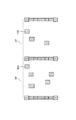
図2(A)、(B)はロジックデバイスに使われるスタンダードセル10、12を模式的に表わした図である。スタンダードセル10には、複数配置された四角形の図形(パターン要素)を含むカットパターン16A(第1パターン)がある。スタンダードセル12にも、同様に、複数配置された四角形の図形(パターン要素)を含むカットパターン16B(第1パターン)がある。第1パターンは右斜め線で示される。スタンダードセル10の第1パターン16Aとスタンダードセル12の第1パターン16Bは、パターン要素の形状が同じで配置が互いに異なっている。ただし、パターン要素の形状は互いに異なっていてもよい。なお、カットパターンは、1方向に延びるパターンで構成されるレイアウトにおけるカット用のパターンである。
2A and 2B are diagrams schematically showing the
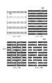
1方向に延びるパターンで構成されるレイアウト(1次元(1D)レイアウトとも呼ぶ)を用いたリソグラフィ技術(Complementary Lithography)を図7を用いて説明する。この1Dレイアウトにより、縦方向にも横方向にも延びるL字パターンなどの複雑な形状のパターン要素を用いずにマスクパターンを構成することができるので、マスクパターンの解像不良を低減することができる。ここで、パターン要素はパターンを構成する要素であって、独立した1つの図形とする。図7は、ハーフピッチが22nm世代のSRAMのゲートセルのリソグラフィプロセスで形成されるパターンを示している。まず、ステップ1において、露光装置を用いて、44nmハーフピッチのラインアンドスペース(L/S)パターン501を基板上に形成する。次に、ステップ2において、基板に形成したパターン501を直接又は下地を加工した後、全面に等方的に成膜し、異方性エッチングを施して、パターン501の側壁(輪郭)に膜を残し22nmハーフピッチのL/S502のハードマスクを形成する。ステップ2は、いわゆる、サイドウォールを用いたダブルパターニング技術を用いている。次に、ステップ3において、L/S502上にレジストを塗布し、L/S502をカットするためのホールパターン503の像をレジストに露光してレジストを現像する。次に、ステップ4において、再度異方性エッチングすることにより、ホールパターン503でL/S502のラインをカットして、1方向に延びたパターンのみで構成されるゲートセルパターン504のハードマスクが形成される。
A lithography technique (Complementary Lithography) using a layout (also referred to as a one-dimensional (1D) layout) composed of patterns extending in one direction will be described with reference to FIG. With this 1D layout, a mask pattern can be formed without using a pattern element having a complicated shape such as an L-shaped pattern extending both in the vertical direction and in the horizontal direction, so that resolution defects of the mask pattern can be reduced. it can. Here, the pattern element is an element constituting the pattern and is an independent figure. FIG. 7 shows a pattern formed by a lithography process of an SRAM gate cell having a half pitch of 22 nm generation. First, in step 1, a 44 nm half pitch line and space (L / S)
ロジックデバイスのパターンについても同様に1Dレイアウトを適用することができる。SRAMのゲートセルやロジックデバイスについて、ラインパターンをカットするためのカットパターンには複数の種類がある。 Similarly, the 1D layout can be applied to the pattern of the logic device. For SRAM gate cells and logic devices, there are a plurality of types of cut patterns for cutting line patterns.
図2(A)、(B)には、ラインアンドスペース(L/S)パターン18A、18Bが参考に示されている。L/Sパターン18A、18Bは、カットパターンよりも前の工程において基板(ウエハ等)上に形成され、カットパターンによりカットされる。また、L/Sパターン18A、18bの各ラインと同様の形状の電源ライン20A、20Bとグラウンドライン22A、22Bが示されている。
2A and 2B, line and space (L / S)
L/Sパターンと電源ラインとグラウンドラインは、1方向に延びるラインが周期的に配列された周期パターンであり、1次元レイアウトに使用される。ただし、L/Sパターン、電源ラインとグラウンドラインは便宜的に図示してあるだけであり、スタンダードセル10とスタンダードセル12には含まれていない。L/Sパターン18A、18Bは、カットパターンに重なっている部分で切断されるが、電源ラインとグラウンドラインはカットしないで使用するため、カットパターンにより切断されない。なお、点線14A、14Bはセルの範囲(外枠)を示す境界線である。図3に示すように、マスクパターンのレイアウト作成の際に、スタンダードセル10とスタンダードセル12が隣接して配置されると、セルの境界線が互いに重なる。また、スタンダードセル10のカットパターンとスタンダードセル12のカットパターンが境界線上で重なることもある。
The L / S pattern, the power supply line, and the ground line are periodic patterns in which lines extending in one direction are periodically arranged, and are used for a one-dimensional layout. However, the L / S pattern, the power supply line, and the ground line are only shown for convenience, and are not included in the
次に、ステップS104で、スタンダードセル10とスタンダードセル12のそれぞれに、第1パターンとは異なるパターン(第2パターン)を追加して配置する。スタンダードセル10に第2パターンが追加されて出来たセル20と、スタンダードセル12に第2パターンが追加されて出来たセル22を図4A、Bに示す。追加された第2パターンは内部が左斜め線で示される。スタンダードセル10には第2パターン24Aが追加されてセル20となり、スタンダードセル12には第2パターン24Bが追加されてセル22となる。第2パターンの大きさは第1パターンと同じで、四角形状の孤立パターンとした。第2パターンの追加配置は、第1パターンに対する光近接効果を補正する目的とは別に行われる。第2パターンおよび第1パターンに対するOPCは後述のS106で行われる。
Next, in step S104, a pattern (second pattern) different from the first pattern is additionally arranged in each of the
第2パターン24A、24Bはともに、L/Sパターン18A、18Bが延びる方向に対して垂直な方向に延びる境界線上に配置されている。左右の境界線のそれぞれにおいて、カットパターン16A、Bの位置以外に第2パターン24A、24Bを配置することにより、カットパターン16A、Bと第2パターン24A、24Bは一列のライン状のパターン(図形)を形成する。
The
1Dレイアウトでは、ラインパターン18A、Bをカットするために必要なカットパターンを用いている。そのため、従来、スタンダードセル10とスタンダードセル12には、カットパターン16A、B(第1パターン)しか無い。本実施形態では、カットパターン16A、B(第1パターン)以外にも、本来必要のないダミーの第2パターンを追加する点が従来技術と異なる。第2パターンが配置されている場所では、既に基板上に形成されているラインパターン18A、Bを本来カットする必要がないが、第2パターンが基板上で解像すると、そのラインパターンが第2パターンによりカットされてしまう。しかし、マスクのパターンのレイアウト作成の際に、隣接セルの境界線付近ではラインパターン同士が繋がっている必要がなく、セルの境界線上の場所においてラインパターンがカットされても問題ない。つまり、その場所におけるラインパターンは、基板上に製造されるデバイスの作動上において影響を及ぼさない。本実施形態では、セルの境界線の位置でラインパターン18A、Bの全てがカットされる。
In the 1D layout, a cut pattern necessary for cutting the
次に、ステップS106で、第1パターンと、追加して配置された第2パターンとを含む各セルに対して個別に光近接効果補正(OPC)の処理を行う。OPCでは、近接する各パターンからの光が相互作用してパターンの像の形成に及ぼす影響(光近接効果(OPE:Optical Proximity Effect))を考慮して、パターンの像が目標範囲に収まるように各パターン要素(図形)の形状を変更する補正を行う。OPCはルールベースOPCでもモデルベースOPCでも良く、公知の補正方法が適用できる。図5A、Bにセル20、セル22に対してOPCをかけた後のセル20´、22´を示す。カットパターン16A、B、および、第2パターン24A、Bの形状が補正されて、それぞれカットパターン16A´、B´、第2パターン24A´、B´となっている。特許文献1では、セルごとに予めOPCをかけているが、カット工程に必要なパターン(第1パターン)のみに対してOPCをしており、本実施形態の第2パターンを追加配置しておらず、第2パターンと第1パターンの光近接効果が考慮されていない。
Next, in step S106, an optical proximity effect correction (OPC) process is individually performed on each cell including the first pattern and the additionally arranged second pattern. In OPC, the light from each adjacent pattern interacts and affects the formation of the pattern image (Optical Proximity Effect (OPE)) so that the pattern image falls within the target range. Correction for changing the shape of each pattern element (figure) is performed. OPC may be rule-based OPC or model-based OPC, and a known correction method can be applied. FIGS. 5A and 5B show the
なお、OPCはセル毎に行ったが、マスクパターンの作成の際に組み合わせて使用される一組のセルがあれば、一組の複数セル同士が及ぼす光近接効果を考慮して一組のセルに対してOPCを行っても良い。また、セルの境界線上にあるパターンのOPC後の形状は、セルの配置で隣り合わせになる可能性のあるセル同士で同じ形状にしておくことが望ましい。なぜならば、セル境界線上にあるパターンはセル配置後に隣り合うセル同士で重なって配置される。そのため、形状が異なるとセル配置前後で、セル内部(境界線よりも内側)のパターンと境界線上のパターンとの間の光近接効果が変化してしまう。一般的にはセル境界線上のパターンは全てのセルで同一形状とし、境界線を対称軸として線対称であることが便利である。そのため、S106において、複数のセルのそれぞれの境界線にあるパターンが互いに同じ形状となるように、第1パターンと第2パターンを含むパターンに対して光近接効果補正を行う。そうすれば、どのセルが隣り合ってもセル境界線上のパターンは同じになり、セル境界線上のパターン形状を特別に管理しなくても済む。 Although OPC is performed for each cell, if there is a set of cells that are used in combination when creating a mask pattern, a set of cells is considered in consideration of the optical proximity effect exerted by a set of multiple cells. OPC may be performed on the. In addition, it is desirable that the shape after the OPC of the pattern on the cell boundary line is the same for cells that may be adjacent to each other in the cell arrangement. This is because the patterns on the cell boundary line are arranged so as to overlap each other after the cell arrangement. Therefore, if the shapes are different, the optical proximity effect between the pattern inside the cell (inside the boundary line) and the pattern on the boundary line changes before and after the cell placement. In general, it is convenient that the pattern on the cell boundary line has the same shape in all the cells and is line symmetric with respect to the boundary line as a symmetry axis. Therefore, in S106, the optical proximity effect correction is performed on the pattern including the first pattern and the second pattern so that the patterns on the boundary lines of the plurality of cells have the same shape. By doing so, the pattern on the cell boundary line is the same regardless of which cells are adjacent to each other, and the pattern shape on the cell boundary line need not be specially managed.
次に、ステップS108で、OPC済みのセル20´、22´を含む複数のセルを、製造するデバイスチップの回路設計に基づいて並べて配置して、マスクパターンのレイアウト(チップレイアウト)を作成する。図6に、セル20´、22´を境界線で隣接して配置した図を示す。なお、実際のマスクのレイアウトには、多数のセルが上下左右に結合して配置されるが、説明簡略化のため、この図では省略されている。セル20´の右側の境界線上のパターン形状と、セル22´の左側の境界線上のパターン形状とは一致しているので、ちょうど重なったパターンとなっている。
Next, in step S108, a plurality of cells including the OPC-completed cells 20 'and 22' are arranged and arranged based on the circuit design of the device chip to be manufactured, thereby creating a mask pattern layout (chip layout). FIG. 6 shows a diagram in which the
次に、ステップS110で、マスクのパターンとして配置された複数のセルのパターンに対してOPC(フルチップレベルのOPC)を行う。このとき、既に各セルには個別にOPCがかけられていることと、セルの境界線に追加された第2パターンが配置されていることにより、従来技術と比較して、S110で行うマスクのパターンのOPCのための計算処理量が少なくて済む。各セルのパターンが既に個別にOPCがされている分、フルチップレベルのOPCで、一部のパターン要素について既にその投影像が目標範囲に収まっていれば補正を施す必要がなくなるので、補正をすべきパターン要素の数や、パターン要素の形状の部分的に変更する箇所の数が減る。したがって、マスクのパターンのOPCにかかる計算時間を短縮することができる。 Next, in step S110, OPC (full chip level OPC) is performed on a plurality of cell patterns arranged as a mask pattern. At this time, since the OPC has already been applied to each cell and the second pattern added to the cell boundary is arranged, the mask of S110 is compared with the conventional technique. The amount of calculation processing for pattern OPC is small. Since the pattern of each cell has already been individually OPCed, it is not necessary to perform correction if the projected image is already within the target range for some pattern elements by OPC at full chip level. The number of pattern elements to be reduced and the number of portions where the shape of the pattern elements is partially changed are reduced. Therefore, the calculation time required for OPC of the mask pattern can be shortened.
セル境界線上に第2パターンが配置されていることにより、S110でのOPCによる補正量が減る理由を以下に説明する。図6のようにセル20´、22´が隣接して配置されたマスクのレイアウトにおいて、セル20´の第1パターンは、他のパターンによる光近接効果を受ける。つまり、セル20´の第1パターンは、セル20´内の第1パターン同士による光近接効果、セル20´に追加された第2パターンによる光近接効果、および、セル22´のパターンによる光近接効果の影響を受ける。セル20´内の第1パターンおよび第2パターンからの光近接効果は、S106におけるセル20単体でのOPCによって補正済みなので、S110でのOPCは主にセル22´のパターンからの光近接効果の補正を行うことになる。セル20´内に第2パターンがあることによって、第1パターンに対する光近接効果の絶対的な量は増えるが、その結果、第2パターンに対して相対的に遠くにあるセル22´のパターンからの光近接効果の量は相対的に減ることになる。光近接効果の影響は一般にパターン間の距離が遠いほど小さくなるからである。このように、相対的に遠くにあるセル22´のパターンからの近接効果の影響を減らし、相対的に近くにあるセル20´自身の第2パターンからの近接効果の影響が大きく、支配的になることによって、S110でのOPCによるセル20´のパターンの形状を変更すべき量や、形状を変更すべきパターン要素の数や部分的に変更する箇所の数が減る。S110でのOPCによるセル22´のパターンも同様である。
The reason why the correction amount by OPC in S110 is reduced by arranging the second pattern on the cell boundary line will be described below. In the mask layout in which the cells 20 'and 22' are arranged adjacent to each other as shown in FIG. In other words, the first pattern of the
次に、ステップS112で、S110でOPCがされたパターンを含むパターンを最終的にマスクのパターンとして作成する。なお、作成されるマスクのパターンにはアライメントマークパターンなど、上記ステップで作成されていない他のパターンが含まれても構わない。 Next, in step S112, a pattern including the pattern subjected to OPC in S110 is finally created as a mask pattern. Note that the mask pattern to be created may include other patterns not created in the above steps, such as an alignment mark pattern.
以上により、本実施形態によれば、S110で行うマスクのパターンの光近接効果補正に要する計算量を減らすことができる。 As described above, according to the present embodiment, it is possible to reduce the calculation amount required for the optical proximity effect correction of the mask pattern performed in S110.
本実施形態では、セルの境界線上のパターン形状は、図4に示したように、上下対称かつ左右対称なひと固まりの連続したパターンであったが、対称性は崩れても構わず、また、不連続な複数のパターンであっても構わない。また、セルの境界線上のパターンの形状は一つのセルライブラリ内で統一されている必要は必ずしもなく、隣り合わされる可能性のあるセル同士においてなるべく同じ形状であることが望まれるにすぎない。また、セルに追加して配置する第2パターンは、セルの境界線上に限らず、ラインパターンのうち、カット工程を経て製造されるデバイスの作動上問題のないライン上に対応する任意の位置に配置されても構わない。例えば、デバイスの作動上問題のないライン上で、セルの境界線より少し内側の位置や、セルの第1パターンに対して解像性を向上させるような位置に配置してもよい。また、露光処理において、第2パターンの像が基板上で解像して基板上に形成されることを説明したが、第2パターンは解像しなくても構わず、第1パターンの解像を補助する解像しない補助パターンとして機能してもよい。 In the present embodiment, the pattern shape on the boundary line of the cell is a continuous pattern of a vertically symmetrical and left-right symmetric mass as shown in FIG. 4, but the symmetry may be lost, A plurality of discontinuous patterns may be used. Further, the shape of the pattern on the cell boundary line does not necessarily need to be unified in one cell library, and it is only desired that the cells that may be adjacent to each other have the same shape as much as possible. In addition, the second pattern to be arranged in addition to the cell is not limited to the boundary line of the cell, but is located at an arbitrary position corresponding to a line in the line pattern that has no problem in operation of the device manufactured through the cutting process. It may be arranged. For example, it may be arranged on a line that does not cause a problem in the operation of the device, at a position slightly inside the boundary line of the cell, or at a position that improves the resolution with respect to the first pattern of the cell. In the exposure process, the image of the second pattern is resolved on the substrate and formed on the substrate. However, the second pattern may not be resolved, and the first pattern is resolved. It may function as an auxiliary pattern that does not resolve and assists.
また、本実施形態では、セルライブラリから選択されるセルのパターンは、1方向に延びるパターンで構成されるレイアウトにおけるカット用のパターンとしたが、これに限らない。例えば、ラインパターン間を接続するためのホールパターンなど他のパターンにも適用することができる。 In the present embodiment, the cell pattern selected from the cell library is a cut pattern in a layout composed of patterns extending in one direction, but is not limited thereto. For example, the present invention can be applied to other patterns such as a hole pattern for connecting line patterns.
また、本実施形態では光近接効果補正において、マスクを照明する照明光学系の瞳面における光強度分布(照明形状)を考慮しても構わない。例えば、照明形状を変更しながらパターンの形状も変更してパターンの像を計算して評価することによって、最適なパターンと照明形状を決定することができる。 In the present embodiment, in the optical proximity effect correction, the light intensity distribution (illumination shape) on the pupil plane of the illumination optical system that illuminates the mask may be considered. For example, the optimal pattern and illumination shape can be determined by changing the illumination shape and changing the pattern shape to calculate and evaluate the pattern image.
(実施形態2)
本実施形態においては、セルライブラリを構成するセルのパターンを作成する。実施形態1では、S106において、第2パターンが追加されたセルのパターンに対してOPCを行った。本実施形態でも、実施形態1と同様にS102、S104、S106を行って、OPC済みのセルのパターンを作成する。ただし、S108以降は行わずに、S106でOPCが施されたセルを、新たなセルとしてセルライブライリに登録して、新しいセルライブラリを作成する。セルのパターンを作成する方法は、実施形態1と同様に、コンピュータがプログラムを実行することにより行われる。
(Embodiment 2)
In the present embodiment, a pattern of cells constituting the cell library is created. In the first embodiment, OPC is performed on the cell pattern to which the second pattern is added in S106. Also in the present embodiment, S102, S104, and S106 are performed in the same manner as in the first embodiment to create a pattern of OPC-completed cells. However, without performing S108 and subsequent steps, the cell that has been subjected to OPC in S106 is registered in the cell library as a new cell, and a new cell library is created. A method of creating a cell pattern is performed by a computer executing a program, as in the first embodiment.
作成された新たなセルライブラリは、別途、マスクのパターンを作成するためのアプリケーション(ソフトウェア)に登録されて、マスクパターンを作成する際に利用される。例えば、マスクのパターンを作成するためのアプリケーション(ソフトウェア)を用いて、本実施形態の作成方法によって作成されて、新たなセルライブラリに登録されたセルのパターンをそのセルライブライリから選択する。選択された複数のセルを並べて配置することでマスクのレイアウトを作成し、OPCをかける。つまり、S106以前のステップと、S108以降のステップとを別々のアプリケーションで実行することができる。 The created new cell library is separately registered in an application (software) for creating a mask pattern and used when creating a mask pattern. For example, by using an application (software) for creating a mask pattern, a cell pattern created by the creation method of the present embodiment and registered in a new cell library is selected from the cell library. A mask layout is created by arranging a plurality of selected cells side by side, and OPC is applied. That is, the steps before S106 and the steps after S108 can be executed by different applications.
(実施形態3)
上述の実施形態で作成されたマスクパターンは、マスク製造装置(描画装置)に入力されるデータの形式に合わせてデータ変換され、そのデータがマスク製造装置に入力される。そして、マスク製造装置は、その入力データに基づき、マスクブランクスにパターンを描画してマスクを製造する。
(Embodiment 3)
The mask pattern created in the above-described embodiment is subjected to data conversion in accordance with the format of data input to the mask manufacturing apparatus (drawing apparatus), and the data is input to the mask manufacturing apparatus. And a mask manufacturing apparatus draws a pattern on mask blanks based on the input data, and manufactures a mask.
製造されたマスクは露光装置に搬入される。露光装置は、設定された露光条件(照明形状、露光量、ステージ移動速度など)で、製造されたマスクを照明して、ウエハ上の感光剤(レジスト)にマスクのパターンの像を投影して感光剤を露光する。 The manufactured mask is carried into an exposure apparatus. The exposure apparatus illuminates the manufactured mask under the set exposure conditions (illumination shape, exposure amount, stage movement speed, etc.), and projects an image of the mask pattern onto the photosensitive agent (resist) on the wafer. Expose the photosensitizer.
次に、前述の露光方法を利用したデバイス(半導体IC素子、液晶表示素子等)の製造方法を説明する。デバイスは、前述の露光方法を使用して、感光剤が塗布された基板(ウェハ、ガラス基板等)を露光する工程と、その基板(感光剤)を現像する工程と、他の周知の工程と、を経ることにより製造される。他の周知の工程には、エッチング、レジスト剥離、ダイシング、ボンディング、パッケージング等が含まれる。なお、デバイス製造方法においては、図7に示すように、1Dレイアウトを用いたリソグラフィ技術を適用することができる。本デバイス製造方法によれば、従来よりも高品位のデバイスを製造することができる。 Next, a method for manufacturing a device (semiconductor IC element, liquid crystal display element, etc.) using the above-described exposure method will be described. The device uses the exposure method described above to expose a substrate (wafer, glass substrate, etc.) coated with a photosensitive agent, to develop the substrate (photosensitive agent), and other known steps. It is manufactured by going through. Other known processes include etching, resist stripping, dicing, bonding, packaging, and the like. In the device manufacturing method, as shown in FIG. 7, a lithography technique using a 1D layout can be applied. According to this device manufacturing method, it is possible to manufacture a higher quality device than before.
また、上述の実施形態では、露光装置に用いられるマスクのパターンの作成に関して説明したが、これに限らず、電子線露光装置で基板に描画するためのパターン(制御データ)の作成にも適用できる。電子線露光装置は、パターンデータに基づいて電子線の描画位置を制御して、基板上にパターンを露光する。上述のパターン作成方法における光近接効果補正としては、電子線露光装置においては、電子線を露光した位置以外にも、形成されるパターンに影響を及ぼす光近接効果の補正がある。 In the above-described embodiment, the creation of the pattern of the mask used in the exposure apparatus has been described. However, the present invention is not limited to this, and the present invention can be applied to the creation of a pattern (control data) for drawing on the substrate by the electron beam exposure apparatus. . The electron beam exposure apparatus controls the drawing position of the electron beam based on the pattern data to expose the pattern on the substrate. As the optical proximity effect correction in the above-described pattern creation method, in the electron beam exposure apparatus, there is a correction of the optical proximity effect that affects the pattern to be formed in addition to the position where the electron beam is exposed.
以上、本発明の好ましい実施形態について説明したが、本発明はこれらの実施形態に限定されず、その要旨の範囲内で種々の変形および変更が可能である。 As mentioned above, although preferable embodiment of this invention was described, this invention is not limited to these embodiment, A various deformation | transformation and change are possible within the range of the summary.
Claims (10)
複数のセルを含むセルライブラリからセルを選択する工程と、
選択されたセル内に、選択されたセルの第1パターンとは異なる第2パターンを前記第1パターンに接するように追加して配置し、前記第1パターンと前記第2パターンを含むライン状のパターンを形成する配置工程と、
前記第1パターンと前記第2パターンを含むライン状のパターンを含む前記選択されたセルのパターンに対して第1光近接効果補正を行う工程と、
前記第1光近接効果補正がなされた前記第1パターンと前記第2パターンを含むライン状のパターンを含む前記選択されたセルとその他のセルが近接して配置された複数のセルのパターンに対して第2光近接効果補正を行う工程と、
前記第2光近接効果補正がなされた前記複数のセルのパターンを含むマスクのパターンを作成する作成工程とを情報処理装置が行い、
作成されたマスクのパターンにおける前記第1パターンと前記第2パターンを含むライン状のパターンは、基板上に形成された1方向に延びるラインパターン上に解像され、解像された前記第1パターンと前記第2パターンを含むライン状のパターンによって前記ラインパターンをカットするためのパターンであり、
前記配置工程において、前記基板上に形成された前記カットされたラインパターンを含むデバイスの作動に影響を及ぼさない位置に前記第2パターンを配置する
ことを特徴とする作成方法。 In the creation method to create a mask pattern,
Selecting a cell from a cell library including a plurality of cells;
In the selected cell, a second pattern different from the first pattern of the selected cell is additionally arranged so as to be in contact with the first pattern, and a line shape including the first pattern and the second pattern is arranged. An arrangement step of forming a pattern;
Performing a first optical proximity effect correction on a pattern of the selected cell including a linear pattern including the first pattern and the second pattern;
For the pattern of a plurality of cells in which the selected cell including the line pattern including the first pattern and the second pattern subjected to the first optical proximity effect correction and the other cells are arranged close to each other Performing a second optical proximity effect correction,
An information processing apparatus performs a creation step of creating a mask pattern including the plurality of cell patterns subjected to the second optical proximity effect correction,
The line-shaped pattern including the first pattern and the second pattern in the pattern of the created mask is resolved on the line pattern extending in one direction formed on the substrate and resolved. pattern der for cutting the line pattern by a line-shaped pattern including the second pattern is,
The creation method , wherein, in the placement step, the second pattern is placed at a position that does not affect the operation of the device including the cut line pattern formed on the substrate .
前記第1光近接効果補正の工程において、前記複数のセルのそれぞれの境界線にあるパターンが互いに同じ形状となるように、前記第1パターンと前記第2パターンを含むパターンに対して光近接効果補正を行うことを特徴とする請求項1又は2に記載の作成方法。 The plurality of cells including the first pattern and the second pattern subjected to the optical proximity effect correction by performing the arrangement step and the first optical proximity effect correction step for a plurality of cells having different first patterns. Create a cell for
In the step of correcting the first optical proximity effect, the optical proximity effect is applied to the pattern including the first pattern and the second pattern so that the patterns on the boundary lines of the plurality of cells have the same shape. the method of creating according to claim 1 or 2, characterized in that to correct.
製造されたマスクを用いて基板を露光する工程とを有することを特徴とする露光方法。 A step of manufacturing a mask using the mask manufacturing method according to claim 5 ;
And exposing the substrate using the manufactured mask.
露光された基板を現像する工程とを有し、現像された基板から物品を製造することを特徴とする物品の製造方法。 Exposing the substrate using the exposure method according to claim 6 ;
And developing the exposed substrate, and manufacturing the article from the developed substrate.
該作成されたパターンのデータを用いて、前記電子線露光装置により基板を露光する工程とを有することを特徴とする露光方法。 A step of creating pattern data used in an electron beam exposure apparatus using the creation method according to any one of claims 1 to 4 ,
And a step of exposing the substrate with the electron beam exposure apparatus using the created pattern data.
Priority Applications (2)
| Application Number | Priority Date | Filing Date | Title |
|---|---|---|---|
| JP2014107477A JP6418786B2 (en) | 2013-07-10 | 2014-05-23 | Pattern creating method, program, and information processing apparatus |
| US14/321,669 US9383638B2 (en) | 2013-07-10 | 2014-07-01 | Method for generating pattern, storage medium, and information processing apparatus |
Applications Claiming Priority (3)
| Application Number | Priority Date | Filing Date | Title |
|---|---|---|---|
| JP2013144757 | 2013-07-10 | ||
| JP2013144757 | 2013-07-10 | ||
| JP2014107477A JP6418786B2 (en) | 2013-07-10 | 2014-05-23 | Pattern creating method, program, and information processing apparatus |
Publications (3)
| Publication Number | Publication Date |
|---|---|
| JP2015034973A JP2015034973A (en) | 2015-02-19 |
| JP2015034973A5 JP2015034973A5 (en) | 2017-07-06 |
| JP6418786B2 true JP6418786B2 (en) | 2018-11-07 |
Family
ID=52277346
Family Applications (1)
| Application Number | Title | Priority Date | Filing Date |
|---|---|---|---|
| JP2014107477A Active JP6418786B2 (en) | 2013-07-10 | 2014-05-23 | Pattern creating method, program, and information processing apparatus |
Country Status (2)
| Country | Link |
|---|---|
| US (1) | US9383638B2 (en) |
| JP (1) | JP6418786B2 (en) |
Families Citing this family (8)
| Publication number | Priority date | Publication date | Assignee | Title |
|---|---|---|---|---|
| JP6468792B2 (en) * | 2014-10-21 | 2019-02-13 | 日本コントロールシステム株式会社 | Pattern correction amount calculation apparatus, pattern correction amount calculation method, and program |
| US10380307B1 (en) * | 2016-03-30 | 2019-08-13 | Silicon Technologies, Inc. | Analog design tool, cell set, and related methods, systems and equipment |
| CN106486063A (en) * | 2016-10-26 | 2017-03-08 | 京东方科技集团股份有限公司 | Pixel-driving circuit and its driving method, display floater and display device |
| US10691849B2 (en) | 2017-09-28 | 2020-06-23 | Taiwan Semiconductor Manufacturing Co., Ltd. | Metal cut optimization for standard cells |
| KR102632559B1 (en) * | 2018-08-23 | 2024-02-02 | 삼성전자주식회사 | Method of manufacturing semiconductor device, method of extreme ultraviolet ray exposure and Method of optical proximity correction |
| CN109508494A (en) * | 2018-11-12 | 2019-03-22 | 北京华大九天软件有限公司 | Accelerate the method for exposure simulation in a kind of panel layout design |
| KR20210010773A (en) | 2019-07-19 | 2021-01-28 | 삼성전자주식회사 | Method of designing a mask and method of manufacturing a semiconductor device using the same |
| CN111596528B (en) * | 2020-05-25 | 2023-02-03 | 上海华力集成电路制造有限公司 | Polycrystalline silicon cutting pattern adding method |
Family Cites Families (12)
| Publication number | Priority date | Publication date | Assignee | Title |
|---|---|---|---|---|
| US5682323A (en) * | 1995-03-06 | 1997-10-28 | Lsi Logic Corporation | System and method for performing optical proximity correction on macrocell libraries |
| JP3311244B2 (en) * | 1996-07-15 | 2002-08-05 | 株式会社東芝 | Basic cell library and method of forming the same |
| US7010764B2 (en) * | 2003-04-14 | 2006-03-07 | Takumi Technology Corp. | Effective proximity effect correction methodology |
| US7355673B2 (en) * | 2003-06-30 | 2008-04-08 | Asml Masktools B.V. | Method, program product and apparatus of simultaneous optimization for NA-Sigma exposure settings and scattering bars OPC using a device layout |
| JP4592438B2 (en) * | 2005-02-08 | 2010-12-01 | 株式会社東芝 | Semiconductor integrated circuit layout method, manufacturing method, and layout program |
| JP4744980B2 (en) * | 2005-08-25 | 2011-08-10 | 株式会社東芝 | Pattern verification method, program thereof, and method of manufacturing semiconductor device |
| WO2008090816A1 (en) * | 2007-01-26 | 2008-07-31 | National Institute Of Advanced Industrial Science And Technology | Mask pattern designing method and semiconductor device fabrication method |
| US8286107B2 (en) | 2007-02-20 | 2012-10-09 | Tela Innovations, Inc. | Methods and systems for process compensation technique acceleration |
| JP2011238713A (en) * | 2010-05-07 | 2011-11-24 | Sharp Corp | Method for designing semiconductor integrated circuit |
| JP2012033923A (en) * | 2010-07-29 | 2012-02-16 | Nikon Corp | Exposure method and exposure apparatus, and method of manufacturing device |
| JP5744564B2 (en) * | 2011-02-25 | 2015-07-08 | キヤノン株式会社 | Drawing apparatus, drawing method, and article manufacturing method |
| US8885917B2 (en) * | 2011-12-27 | 2014-11-11 | United Microelectronics Corp. | Mask pattern and correcting method thereof |
-
2014
- 2014-05-23 JP JP2014107477A patent/JP6418786B2/en active Active
- 2014-07-01 US US14/321,669 patent/US9383638B2/en active Active
Also Published As
| Publication number | Publication date |
|---|---|
| US9383638B2 (en) | 2016-07-05 |
| US20150017572A1 (en) | 2015-01-15 |
| JP2015034973A (en) | 2015-02-19 |
Similar Documents
| Publication | Publication Date | Title |
|---|---|---|
| JP6418786B2 (en) | Pattern creating method, program, and information processing apparatus | |
| US8166424B2 (en) | Method for constructing OPC model | |
| JP4852083B2 (en) | Pattern data creation method and pattern data creation program | |
| US10720419B2 (en) | Layout modification method for exposure manufacturing process | |
| TWI485509B (en) | Pattern generation method | |
| TWI742184B (en) | Target optimization method | |
| TW200532398A (en) | Design pattern correction method, mask producing method , semiconductor device producing method, mask pattern producing method, design pattern correction system and recording media | |
| TW201923443A (en) | Method for mask making | |
| TW201923442A (en) | Method for integrated circuit fabrication | |
| CN102117010B (en) | Optical adjacent correcting method | |
| JP2005338650A (en) | Data generation method for pattern and pattern verification method | |
| TWI722454B (en) | Method and system for improving critical dimension uniformity | |
| JP2006171113A (en) | Mask data preparation apparatus, mask data preparation method, exposure mask, method for manufacturing semiconductor device, and mask data preparation program | |
| JP6399751B2 (en) | Mask pattern creation method, program, mask manufacturing method, exposure method, and article manufacturing method | |
| JP6324044B2 (en) | Cell pattern creation method, mask pattern creation method, program, information processing apparatus, and mask manufacturing method | |
| TWI421908B (en) | Method for constructing opc model | |
| JP2008020734A (en) | Design pattern preparation method for semiconductor device, program, and method of manufacturing the semiconductor device | |
| US9547230B2 (en) | Method for evaluating optical image of pattern, recording medium, and information processing apparatus | |
| JP2012042498A (en) | Method for forming mask pattern and method for forming lithography target pattern | |
| US8383299B2 (en) | Double patterning mask set and method of forming thereof | |
| JP2012198411A (en) | Mask pattern correction method, mask pattern correction program, and method of manufacturing semiconductor device | |
| JP5322443B2 (en) | Mask pattern data generation method and semiconductor device manufacturing method | |
| JP2007041024A (en) | Drawing data generating program, electron beam lithography system, and method for manufacturing mask | |
| JP6415154B2 (en) | Pattern creating method, program, and information processing apparatus | |
| TW201913227A (en) | Method of generating a mask pattern |
Legal Events
| Date | Code | Title | Description |
|---|---|---|---|
| A521 | Written amendment |
Free format text: JAPANESE INTERMEDIATE CODE: A523 Effective date: 20170522 |
|
| A621 | Written request for application examination |
Free format text: JAPANESE INTERMEDIATE CODE: A621 Effective date: 20170522 |
|
| A977 | Report on retrieval |
Free format text: JAPANESE INTERMEDIATE CODE: A971007 Effective date: 20180221 |
|
| A131 | Notification of reasons for refusal |
Free format text: JAPANESE INTERMEDIATE CODE: A131 Effective date: 20180313 |
|
| A521 | Written amendment |
Free format text: JAPANESE INTERMEDIATE CODE: A523 Effective date: 20180510 |
|
| A131 | Notification of reasons for refusal |
Free format text: JAPANESE INTERMEDIATE CODE: A131 Effective date: 20180605 |
|
| A521 | Written amendment |
Free format text: JAPANESE INTERMEDIATE CODE: A523 Effective date: 20180803 |
|
| TRDD | Decision of grant or rejection written | ||
| A01 | Written decision to grant a patent or to grant a registration (utility model) |
Free format text: JAPANESE INTERMEDIATE CODE: A01 Effective date: 20180911 |
|
| A61 | First payment of annual fees (during grant procedure) |
Free format text: JAPANESE INTERMEDIATE CODE: A61 Effective date: 20181009 |
|
| R151 | Written notification of patent or utility model registration |
Ref document number: 6418786 Country of ref document: JP Free format text: JAPANESE INTERMEDIATE CODE: R151 |