JP6403978B2 - Machine Tools - Google Patents
Machine Tools Download PDFInfo
- Publication number
- JP6403978B2 JP6403978B2 JP2014085769A JP2014085769A JP6403978B2 JP 6403978 B2 JP6403978 B2 JP 6403978B2 JP 2014085769 A JP2014085769 A JP 2014085769A JP 2014085769 A JP2014085769 A JP 2014085769A JP 6403978 B2 JP6403978 B2 JP 6403978B2
- Authority
- JP
- Japan
- Prior art keywords
- pallet
- workpiece
- main body
- body cover
- machine tool
- Prior art date
- Legal status (The legal status is an assumption and is not a legal conclusion. Google has not performed a legal analysis and makes no representation as to the accuracy of the status listed.)
- Active
Links
Images


Classifications
-
- B—PERFORMING OPERATIONS; TRANSPORTING
- B23—MACHINE TOOLS; METAL-WORKING NOT OTHERWISE PROVIDED FOR
- B23Q—DETAILS, COMPONENTS, OR ACCESSORIES FOR MACHINE TOOLS, e.g. ARRANGEMENTS FOR COPYING OR CONTROLLING; MACHINE TOOLS IN GENERAL CHARACTERISED BY THE CONSTRUCTION OF PARTICULAR DETAILS OR COMPONENTS; COMBINATIONS OR ASSOCIATIONS OF METAL-WORKING MACHINES, NOT DIRECTED TO A PARTICULAR RESULT
- B23Q7/00—Arrangements for handling work specially combined with or arranged in, or specially adapted for use in connection with, machine tools, e.g. for conveying, loading, positioning, discharging, sorting
- B23Q7/14—Arrangements for handling work specially combined with or arranged in, or specially adapted for use in connection with, machine tools, e.g. for conveying, loading, positioning, discharging, sorting co-ordinated in production lines
- B23Q7/1426—Arrangements for handling work specially combined with or arranged in, or specially adapted for use in connection with, machine tools, e.g. for conveying, loading, positioning, discharging, sorting co-ordinated in production lines with work holders not rigidly fixed to the transport devices
- B23Q7/1431—Work holder changers
-
- B—PERFORMING OPERATIONS; TRANSPORTING
- B23—MACHINE TOOLS; METAL-WORKING NOT OTHERWISE PROVIDED FOR
- B23Q—DETAILS, COMPONENTS, OR ACCESSORIES FOR MACHINE TOOLS, e.g. ARRANGEMENTS FOR COPYING OR CONTROLLING; MACHINE TOOLS IN GENERAL CHARACTERISED BY THE CONSTRUCTION OF PARTICULAR DETAILS OR COMPONENTS; COMBINATIONS OR ASSOCIATIONS OF METAL-WORKING MACHINES, NOT DIRECTED TO A PARTICULAR RESULT
- B23Q7/00—Arrangements for handling work specially combined with or arranged in, or specially adapted for use in connection with, machine tools, e.g. for conveying, loading, positioning, discharging, sorting
- B23Q7/02—Arrangements for handling work specially combined with or arranged in, or specially adapted for use in connection with, machine tools, e.g. for conveying, loading, positioning, discharging, sorting by means of drums or rotating tables or discs
-
- B—PERFORMING OPERATIONS; TRANSPORTING
- B23—MACHINE TOOLS; METAL-WORKING NOT OTHERWISE PROVIDED FOR
- B23Q—DETAILS, COMPONENTS, OR ACCESSORIES FOR MACHINE TOOLS, e.g. ARRANGEMENTS FOR COPYING OR CONTROLLING; MACHINE TOOLS IN GENERAL CHARACTERISED BY THE CONSTRUCTION OF PARTICULAR DETAILS OR COMPONENTS; COMBINATIONS OR ASSOCIATIONS OF METAL-WORKING MACHINES, NOT DIRECTED TO A PARTICULAR RESULT
- B23Q1/00—Members which are comprised in the general build-up of a form of machine, particularly relatively large fixed members
- B23Q1/25—Movable or adjustable work or tool supports
- B23Q1/44—Movable or adjustable work or tool supports using particular mechanisms
-
- B—PERFORMING OPERATIONS; TRANSPORTING
- B23—MACHINE TOOLS; METAL-WORKING NOT OTHERWISE PROVIDED FOR
- B23Q—DETAILS, COMPONENTS, OR ACCESSORIES FOR MACHINE TOOLS, e.g. ARRANGEMENTS FOR COPYING OR CONTROLLING; MACHINE TOOLS IN GENERAL CHARACTERISED BY THE CONSTRUCTION OF PARTICULAR DETAILS OR COMPONENTS; COMBINATIONS OR ASSOCIATIONS OF METAL-WORKING MACHINES, NOT DIRECTED TO A PARTICULAR RESULT
- B23Q11/00—Accessories fitted to machine tools for keeping tools or parts of the machine in good working condition or for cooling work; Safety devices specially combined with or arranged in, or specially adapted for use in connection with, machine tools
- B23Q11/08—Protective coverings for parts of machine tools; Splash guards
- B23Q11/0891—Protective coverings for parts of machine tools; Splash guards arranged between the working area and the operator
-
- B—PERFORMING OPERATIONS; TRANSPORTING
- B23—MACHINE TOOLS; METAL-WORKING NOT OTHERWISE PROVIDED FOR
- B23Q—DETAILS, COMPONENTS, OR ACCESSORIES FOR MACHINE TOOLS, e.g. ARRANGEMENTS FOR COPYING OR CONTROLLING; MACHINE TOOLS IN GENERAL CHARACTERISED BY THE CONSTRUCTION OF PARTICULAR DETAILS OR COMPONENTS; COMBINATIONS OR ASSOCIATIONS OF METAL-WORKING MACHINES, NOT DIRECTED TO A PARTICULAR RESULT
- B23Q7/00—Arrangements for handling work specially combined with or arranged in, or specially adapted for use in connection with, machine tools, e.g. for conveying, loading, positioning, discharging, sorting
- B23Q7/14—Arrangements for handling work specially combined with or arranged in, or specially adapted for use in connection with, machine tools, e.g. for conveying, loading, positioning, discharging, sorting co-ordinated in production lines
- B23Q7/1426—Arrangements for handling work specially combined with or arranged in, or specially adapted for use in connection with, machine tools, e.g. for conveying, loading, positioning, discharging, sorting co-ordinated in production lines with work holders not rigidly fixed to the transport devices
- B23Q7/1494—Arrangements for handling work specially combined with or arranged in, or specially adapted for use in connection with, machine tools, e.g. for conveying, loading, positioning, discharging, sorting co-ordinated in production lines with work holders not rigidly fixed to the transport devices using grippers
-
- B—PERFORMING OPERATIONS; TRANSPORTING
- B23—MACHINE TOOLS; METAL-WORKING NOT OTHERWISE PROVIDED FOR
- B23Q—DETAILS, COMPONENTS, OR ACCESSORIES FOR MACHINE TOOLS, e.g. ARRANGEMENTS FOR COPYING OR CONTROLLING; MACHINE TOOLS IN GENERAL CHARACTERISED BY THE CONSTRUCTION OF PARTICULAR DETAILS OR COMPONENTS; COMBINATIONS OR ASSOCIATIONS OF METAL-WORKING MACHINES, NOT DIRECTED TO A PARTICULAR RESULT
- B23Q1/00—Members which are comprised in the general build-up of a form of machine, particularly relatively large fixed members
- B23Q1/25—Movable or adjustable work or tool supports
- B23Q1/44—Movable or adjustable work or tool supports using particular mechanisms
- B23Q1/50—Movable or adjustable work or tool supports using particular mechanisms with rotating pairs only, the rotating pairs being the first two elements of the mechanism
- B23Q1/54—Movable or adjustable work or tool supports using particular mechanisms with rotating pairs only, the rotating pairs being the first two elements of the mechanism two rotating pairs only
- B23Q1/5406—Movable or adjustable work or tool supports using particular mechanisms with rotating pairs only, the rotating pairs being the first two elements of the mechanism two rotating pairs only a single rotating pair followed perpendicularly by a single rotating pair
-
- B—PERFORMING OPERATIONS; TRANSPORTING
- B23—MACHINE TOOLS; METAL-WORKING NOT OTHERWISE PROVIDED FOR
- B23Q—DETAILS, COMPONENTS, OR ACCESSORIES FOR MACHINE TOOLS, e.g. ARRANGEMENTS FOR COPYING OR CONTROLLING; MACHINE TOOLS IN GENERAL CHARACTERISED BY THE CONSTRUCTION OF PARTICULAR DETAILS OR COMPONENTS; COMBINATIONS OR ASSOCIATIONS OF METAL-WORKING MACHINES, NOT DIRECTED TO A PARTICULAR RESULT
- B23Q1/00—Members which are comprised in the general build-up of a form of machine, particularly relatively large fixed members
- B23Q1/25—Movable or adjustable work or tool supports
- B23Q1/44—Movable or adjustable work or tool supports using particular mechanisms
- B23Q1/56—Movable or adjustable work or tool supports using particular mechanisms with sliding pairs only, the sliding pairs being the first two elements of the mechanism
- B23Q1/60—Movable or adjustable work or tool supports using particular mechanisms with sliding pairs only, the sliding pairs being the first two elements of the mechanism two sliding pairs only, the sliding pairs being the first two elements of the mechanism
- B23Q1/62—Movable or adjustable work or tool supports using particular mechanisms with sliding pairs only, the sliding pairs being the first two elements of the mechanism two sliding pairs only, the sliding pairs being the first two elements of the mechanism with perpendicular axes, e.g. cross-slides
- B23Q1/621—Movable or adjustable work or tool supports using particular mechanisms with sliding pairs only, the sliding pairs being the first two elements of the mechanism two sliding pairs only, the sliding pairs being the first two elements of the mechanism with perpendicular axes, e.g. cross-slides a single sliding pair followed perpendicularly by a single sliding pair
- B23Q1/626—Movable or adjustable work or tool supports using particular mechanisms with sliding pairs only, the sliding pairs being the first two elements of the mechanism two sliding pairs only, the sliding pairs being the first two elements of the mechanism with perpendicular axes, e.g. cross-slides a single sliding pair followed perpendicularly by a single sliding pair followed perpendicularly by a single sliding pair
-
- B—PERFORMING OPERATIONS; TRANSPORTING
- B23—MACHINE TOOLS; METAL-WORKING NOT OTHERWISE PROVIDED FOR
- B23Q—DETAILS, COMPONENTS, OR ACCESSORIES FOR MACHINE TOOLS, e.g. ARRANGEMENTS FOR COPYING OR CONTROLLING; MACHINE TOOLS IN GENERAL CHARACTERISED BY THE CONSTRUCTION OF PARTICULAR DETAILS OR COMPONENTS; COMBINATIONS OR ASSOCIATIONS OF METAL-WORKING MACHINES, NOT DIRECTED TO A PARTICULAR RESULT
- B23Q3/00—Devices holding, supporting, or positioning work or tools, of a kind normally removable from the machine
- B23Q3/155—Arrangements for automatic insertion or removal of tools, e.g. combined with manual handling
- B23Q3/157—Arrangements for automatic insertion or removal of tools, e.g. combined with manual handling of rotary tools
- B23Q3/15713—Arrangements for automatic insertion or removal of tools, e.g. combined with manual handling of rotary tools a transfer device taking a single tool from a storage device and inserting it in a spindle
- B23Q3/1572—Arrangements for automatic insertion or removal of tools, e.g. combined with manual handling of rotary tools a transfer device taking a single tool from a storage device and inserting it in a spindle the storage device comprising rotating or circulating storing means
- B23Q3/15753—Arrangements for automatic insertion or removal of tools, e.g. combined with manual handling of rotary tools a transfer device taking a single tool from a storage device and inserting it in a spindle the storage device comprising rotating or circulating storing means the storage means rotating or circulating in a plane perpendicular to the axis of the spindle
- B23Q3/15766—Arrangements for automatic insertion or removal of tools, e.g. combined with manual handling of rotary tools a transfer device taking a single tool from a storage device and inserting it in a spindle the storage device comprising rotating or circulating storing means the storage means rotating or circulating in a plane perpendicular to the axis of the spindle the axis of the stored tools being arranged perpendicularly to the rotating or circulating plane of the storage means
-
- Y—GENERAL TAGGING OF NEW TECHNOLOGICAL DEVELOPMENTS; GENERAL TAGGING OF CROSS-SECTIONAL TECHNOLOGIES SPANNING OVER SEVERAL SECTIONS OF THE IPC; TECHNICAL SUBJECTS COVERED BY FORMER USPC CROSS-REFERENCE ART COLLECTIONS [XRACs] AND DIGESTS
- Y10—TECHNICAL SUBJECTS COVERED BY FORMER USPC
- Y10T—TECHNICAL SUBJECTS COVERED BY FORMER US CLASSIFICATION
- Y10T29/00—Metal working
- Y10T29/51—Plural diverse manufacturing apparatus including means for metal shaping or assembling
- Y10T29/5196—Multiple station with conveyor
-
- Y—GENERAL TAGGING OF NEW TECHNOLOGICAL DEVELOPMENTS; GENERAL TAGGING OF CROSS-SECTIONAL TECHNOLOGIES SPANNING OVER SEVERAL SECTIONS OF THE IPC; TECHNICAL SUBJECTS COVERED BY FORMER USPC CROSS-REFERENCE ART COLLECTIONS [XRACs] AND DIGESTS
- Y10—TECHNICAL SUBJECTS COVERED BY FORMER USPC
- Y10T—TECHNICAL SUBJECTS COVERED BY FORMER US CLASSIFICATION
- Y10T409/00—Gear cutting, milling, or planing
- Y10T409/30—Milling
- Y10T409/30392—Milling with means to protect operative or machine [e.g., guard, safety device, etc.]
-
- Y—GENERAL TAGGING OF NEW TECHNOLOGICAL DEVELOPMENTS; GENERAL TAGGING OF CROSS-SECTIONAL TECHNOLOGIES SPANNING OVER SEVERAL SECTIONS OF THE IPC; TECHNICAL SUBJECTS COVERED BY FORMER USPC CROSS-REFERENCE ART COLLECTIONS [XRACs] AND DIGESTS
- Y10—TECHNICAL SUBJECTS COVERED BY FORMER USPC
- Y10T—TECHNICAL SUBJECTS COVERED BY FORMER US CLASSIFICATION
- Y10T409/00—Gear cutting, milling, or planing
- Y10T409/30—Milling
- Y10T409/304536—Milling including means to infeed work to cutter
- Y10T409/305544—Milling including means to infeed work to cutter with work holder
- Y10T409/305656—Milling including means to infeed work to cutter with work holder including means to support work for rotation during operation
- Y10T409/305824—Milling including means to infeed work to cutter with work holder including means to support work for rotation during operation with angular movement of work
-
- Y—GENERAL TAGGING OF NEW TECHNOLOGICAL DEVELOPMENTS; GENERAL TAGGING OF CROSS-SECTIONAL TECHNOLOGIES SPANNING OVER SEVERAL SECTIONS OF THE IPC; TECHNICAL SUBJECTS COVERED BY FORMER USPC CROSS-REFERENCE ART COLLECTIONS [XRACs] AND DIGESTS
- Y10—TECHNICAL SUBJECTS COVERED BY FORMER USPC
- Y10T—TECHNICAL SUBJECTS COVERED BY FORMER US CLASSIFICATION
- Y10T409/00—Gear cutting, milling, or planing
- Y10T409/30—Milling
- Y10T409/30784—Milling including means to adustably position cutter
- Y10T409/307952—Linear adjustment
- Y10T409/308288—Linear adjustment including gantry-type cutter-carrier
-
- Y—GENERAL TAGGING OF NEW TECHNOLOGICAL DEVELOPMENTS; GENERAL TAGGING OF CROSS-SECTIONAL TECHNOLOGIES SPANNING OVER SEVERAL SECTIONS OF THE IPC; TECHNICAL SUBJECTS COVERED BY FORMER USPC CROSS-REFERENCE ART COLLECTIONS [XRACs] AND DIGESTS
- Y10—TECHNICAL SUBJECTS COVERED BY FORMER USPC
- Y10T—TECHNICAL SUBJECTS COVERED BY FORMER US CLASSIFICATION
- Y10T409/00—Gear cutting, milling, or planing
- Y10T409/30—Milling
- Y10T409/309576—Machine frame
-
- Y—GENERAL TAGGING OF NEW TECHNOLOGICAL DEVELOPMENTS; GENERAL TAGGING OF CROSS-SECTIONAL TECHNOLOGIES SPANNING OVER SEVERAL SECTIONS OF THE IPC; TECHNICAL SUBJECTS COVERED BY FORMER USPC CROSS-REFERENCE ART COLLECTIONS [XRACs] AND DIGESTS
- Y10—TECHNICAL SUBJECTS COVERED BY FORMER USPC
- Y10T—TECHNICAL SUBJECTS COVERED BY FORMER US CLASSIFICATION
- Y10T483/00—Tool changing
- Y10T483/16—Tool changing with means to transfer work
-
- Y—GENERAL TAGGING OF NEW TECHNOLOGICAL DEVELOPMENTS; GENERAL TAGGING OF CROSS-SECTIONAL TECHNOLOGIES SPANNING OVER SEVERAL SECTIONS OF THE IPC; TECHNICAL SUBJECTS COVERED BY FORMER USPC CROSS-REFERENCE ART COLLECTIONS [XRACs] AND DIGESTS
- Y10—TECHNICAL SUBJECTS COVERED BY FORMER USPC
- Y10T—TECHNICAL SUBJECTS COVERED BY FORMER US CLASSIFICATION
- Y10T483/00—Tool changing
- Y10T483/17—Tool changing including machine tool or component
- Y10T483/1733—Rotary spindle machine tool [e.g., milling machine, boring, machine, grinding machine, etc.]
- Y10T483/1748—Tool changer between spindle and matrix
- Y10T483/1752—Tool changer between spindle and matrix including tool holder pivotable about axis
- Y10T483/1755—Plural tool holders pivotable about common axis
Description
この発明は、工作機械の加工空間を本体カバーで覆うと共に、該本体カバーの一方の側部に隣設されて、加工空間内に配置されたテーブルの上面に固定された加工済みのワークを取り付けた第1のパレットと、加工前のワークを取り付けた第2のパレットとを交換するパレット交換装置を有する工作機械に関する。 The present invention covers a machining space of a machine tool with a main body cover, and attaches a processed workpiece fixed on the upper surface of a table arranged in one side of the main body cover and disposed in the machining space. The present invention also relates to a machine tool having a pallet exchanging device for exchanging a first pallet and a second pallet to which a workpiece before processing is attached.
例えば、特許文献1には、工作機械の本体に設けられたワークの加工空間を第1カバーで覆い、この加工空間内に、上面にワークが固定されるテーブルを配置して、前記第1カバーの右側部と連続させた第2カバー内に、前記テーブルの上面に固定されて加工済みのワークを取り付けたパレットと、加工前のワークを取り付けたパレットとを交換するパレット交換装置を備えた工作機械が開示されている。このパレット交換装置は、上面に複数のパレット載置台が設けられて、水平方向に回転移動するパレット移動台と、このパレット移動台と工作機械の本体との間に配置されて、前記パレット移動台によって所定の位置に移動して前記パレット載置台に載置されたパレットを、該パレット載置台と工作機械のテーブルとの間で移送する移送機構とを備えている。
For example, in
そして上記の工作機械では、移送機構に設けられた移送部材が、第1カバーの右側部に形成されたパレット交換孔を通じ、前記テーブルに対して進退可能とされており、該パレット交換孔からパレットの搬入及び搬出を行うことにより、該テーブルの上面に固定されて加工済みのワークを取り付けたパレットと、加工前のワークを取り付けたパレットとを交換している。 In the above machine tool, the transfer member provided in the transfer mechanism can be moved back and forth with respect to the table through the pallet exchange hole formed in the right side portion of the first cover. By carrying in and carrying out, the pallet to which the workpiece that has been processed and fixed to the upper surface of the table is exchanged with the pallet to which the workpiece before machining is attached.
しかしながら、上記の工作機械では、パレット交換装置に、パレット移動台に加えて移送機構が設けられており、パレット移動台によってパレットが所定の位置に移動した直後に、このパレットを移送機構によって工作機械のテーブルに移送できるようにするためには、パレット移動台の動きと移送機構の動きとを同調させる必要があった。このような場合には、パレット移動台と移送機構とを同調させる制御手段も必要になる等の理由により、パレット交換装置の構造が複雑になることが考えられる。 However, in the above machine tool, the pallet exchanging device is provided with a transfer mechanism in addition to the pallet moving table, and immediately after the pallet is moved to a predetermined position by the pallet moving table, the pallet is moved by the transfer mechanism. In order to be able to transfer to the table, it is necessary to synchronize the movement of the pallet moving table and the movement of the transfer mechanism. In such a case, it is conceivable that the structure of the pallet exchanging apparatus becomes complicated due to the necessity of a control means for synchronizing the pallet moving table and the transfer mechanism.
さらに上記のパレット交換装置では、パレット移動台とテーブルとの間でパレットを移送する際に、パレット移動台と移送機構との間でパレットを受け渡しする時間が必要になる。このような場合には、前記パレットの受け渡しに費やす時間が累積されると、加工済みのワークを取り付けたパレットと加工前のワークを取り付けたパレットとの交換に要する時間が長くなることも考えられる。 Furthermore, in the pallet exchanging apparatus described above, when the pallet is transferred between the pallet moving table and the table, it takes time to deliver the pallet between the pallet moving table and the transfer mechanism. In such a case, if the time spent for delivery of the pallet is accumulated, the time required for exchanging the pallet attached with the processed workpiece and the pallet attached with the workpiece before processing may be increased. .
この発明は、このような状況に鑑み提案されたものであって、パレット交換装置の構造を簡素化すると共に、該パレット交換装置によるパレットの交換に要する時間を短縮できる工作機械を提供することを目的とする。 The present invention has been proposed in view of such circumstances, and provides a machine tool that can simplify the structure of a pallet changer and reduce the time required for pallet change by the pallet changer. Objective.
請求項1の発明に係る工作機械は、工作機械の本体に設けられたワークの加工空間において、前記ワークを取り付けたパレットを上面に固定するテーブルと工具とを相対移動させることにより、前記工具によって前記ワークを加工可能として、前記加工空間を本体カバーで覆うと共に、前記本体カバーには、前記加工空間に面して該本体カバーの前面を開閉する第1のドアを設け、前記本体カバーの一方の側部に隣設されて、前記テーブルの上面に固定された加工済みのワークを取り付けた第1のパレットと、加工前のワークを取り付けた第2のパレットとを交換するパレット交換装置を有する工作機械であって、前記パレット交換装置は、両端部に前記第1のパレットと前記第2のパレットとをそれぞれ保持可能な一対の保持部が設けられて、水平方向に旋回自在な旋回部材を備え、前記旋回部材を、前記本体カバーに設けられたワーク搬出入口を通じて前記加工空間内に進退させることを可能にして、前記旋回部材を、前記ワーク搬出入口を通じて前記加工空間内に進入させた後に、前記加工空間内において前記旋回部材を前記水平方向に旋回させることにより、前記加工空間内において、一方の前記保持部に保持した前記第1のパレットを前記テーブルの上面から前記パレット交換装置に搬送すると共に、他方の前記保持部に保持した前記第2のパレットを前記パレット交換装置から前記テーブルの上面に搬送することを可能とする一方、前記パレット交換装置側で、前記旋回部材を前記水平方向に旋回させることにより、前記一方の保持部あるいは前記他方の保持部を、前記パレット交換装置の前方に向けた位置に割り出し可能としたことを特徴とする。 The machine tool according to the first aspect of the present invention is configured to move the table and the tool for fixing the pallet to which the work is mounted on the upper surface in the work space of the work provided in the machine tool main body, by using the tool. The workpiece can be machined, the machining space is covered with a body cover, and the body cover is provided with a first door that opens and closes the front surface of the body cover so as to face the machining space. A pallet exchanging device for exchanging a first pallet attached with a processed workpiece fixed on the upper surface of the table and a second pallet attached with a workpiece before processing. It is a machine tool, and the pallet exchanging device is provided with a pair of holding portions capable of holding the first pallet and the second pallet at both ends. , Comprising a freely pivoting member pivot in a horizontal direction, wherein the pivot member, make it possible to advance and retreat in the in the working space through the workpiece transfer port provided in the body cover, the pivot member, the workpiece transfer port wherein after is advanced into the processing space, the processing by the pivot member in a space be pivoted in the horizontal direction, Oite into the processing space, the first pallet held in one of said holding portions through The pallet can be conveyed from the upper surface of the table to the pallet exchanging device, and the second pallet held in the other holding portion can be conveyed from the pallet exchanging device to the upper surface of the table. On the exchange device side, the one holding part or the other holding part is moved forward by turning the turning member in the horizontal direction. Characterized in that the indexable to a position toward the front of the pallet changer.
請求項2の発明は、請求項1において、前記本体カバーの一方の側方に前記パレット交換装置を覆う側部カバーを設け、該側部カバーに、前記旋回部材に面して前記側部カバーの前面を開閉する第2のドアを設けたことを特徴とする。 According to a second aspect of the present invention, in the first aspect, a side cover that covers the pallet exchanging device is provided on one side of the main body cover, and the side cover faces the swivel member on the side cover. A second door for opening and closing the front surface of the door is provided.
請求項3の発明は、請求項1又は2において、前記テーブルを、前記本体カバーに対する前記旋回部材の接離方向と直交する揺動軸回りで揺動可能に設けたことを特徴とする。 A third aspect of the present invention is characterized in that, in the first or second aspect , the table is provided so as to be swingable about a swinging axis perpendicular to the contact / separation direction of the swiveling member with respect to the main body cover.
請求項4の発明は、請求項3において、前記テーブルの前方及び後方に、前記揺動軸を揺動可能に支持する支持部をそれぞれ配置して、前記後方に配置した支持部の大きさよりも前記前方に配置した支持部の大きさを小さくしたことを特徴とする。 According to a fourth aspect of the present invention, in the third aspect of the present invention, the support portions for swingably supporting the swing shaft are disposed at the front and rear of the table, respectively, and the size of the support portion disposed at the rear is larger. The size of the support portion disposed in front is reduced.
請求項5の発明は、請求項4において、前記テーブルの上面よりも下方であって該テーブルの前面に、前記揺動軸の軸心を中心とする円弧状とされた第1のレール部材を固定し、前記前方に配置した支持部に、前記第1のレール部材と係合する係合部材を設けて、前記揺動軸の揺動によって、前記第1のレール部材が前記係合部材と係合しながら前記揺動軸回りで揺動することに伴って前記テーブルが該揺動軸回りで揺動することを特徴する。
The invention of
請求項6の発明は、請求項5において、前記前方に配置した支持部に、揺動前の前記テーブルの上面よりも下方に位置し、前記係合部材が固定されて前記揺動軸の軸心を中心とする円弧状とされた第2のレール部材を、前記揺動軸回りで揺動可能に支持し、前記第1のレール部材には、前記係合部材に係止されて、該第1のレール部材が前記揺動軸回りで揺動することに伴って前記第2のレール部材を前記揺動軸回りで揺動させる係止部を設けたことを特徴とする。
The invention according to
請求項1の発明に係る工作機械によれば、パレット交換装置に備えられた旋回部材は、水平方向への旋回動作によって、加工済みのワークを取り付けた第1のパレットと、加工前のワークを取り付けた第2のパレットとを、加工空間内において、テーブルとパレット交換装置側との間で搬送できる。これに加えて旋回部材は、本体カバーに対する接離方向への移動動作によって、前記第1のパレットと前記第2のパレットとを、テーブルとパレット交換装置との間で搬送できる。よって、旋回部材に、旋回動作と本体カバーに対する接離方向への移動動作という複数の動作をさせることができるため、該旋回部材を旋回動作させる装置と該旋回部材を本体カバーに対する接離方向への移動動作をさせる装置とを別々に設けた上で、これらの装置を同調させる装置を設ける必要がない。これにより、パレット交換装置の構造を簡素化できる。
さらに、旋回部材によって複数の動作(前記旋回動作及び前記移動動作)をさせることができれば、前記旋回動作をさせる装置と前記移動動作をさせる装置とを別々に設けて、両装置の間でパレットを受け渡す時間(受け渡し時間)が不要になる。これにより、テーブルとパレット交換装置との間で第1のパレットと第2のパレットとを交換する際には、前記受け渡し時間が累積されることがない結果、両パレットの交換に要する時間を短縮できる。
加えて、工作機械の使用者は、パレット交換装置の前方から、旋回部材の一方の保持部に保持された加工済みのワークを取り付けた第1のパレットをパレット交換装置の外側へ搬出したり、パレット交換装置の前方から旋回部材の他方の保持部に向けて、加工前のワークを取り付けた第2のパレットを搬入できる。これにより、工作機械の作業者が、パレット交換装置に対するワークの搬出入作業を行い易くなる。
請求項2の発明によれば、工作機械の使用者は、第2のドアによって側部カバーの前面を開放すると、この開放された前面を通じて旋回部材の一方の保持部から加工済みのワークを取り付けたパレットを側部カバーの外側へ搬出したり、前記開放された前面を通じて側部カバーの外側から旋回部材の他方の保持部に向けて、加工前のワークを取り付けたパレットを搬入できる。したがって、工作機械の本体の前面と側部カバー内に対してワークを搬出入する位置とを接近させることができるため、工作機械の作業者がワークの搬出入作業を行い易くなる。
請求項3の発明によれば、本体カバーに対する旋回部材の接離方向にテーブルの揺動軸が設けられることがない。よって、揺動軸は、テーブルに対する旋回部材の接近を妨げない。
請求項4の発明によれば、例えば、工作機械の使用者が、第1のドアによって開放した本体カバーの前面からテーブル上のワークを確認したり点検する際に、テーブル上のワークがテーブルの前方の支持部に隠れて見え難くなることを抑制できる。これにより、テーブル上のワークの確認や点検が容易になる。
請求項5の発明によれば、テーブルが揺動軸回りで揺動を開始する前や揺動する際には、第1のレール部材がテーブルの前面から上面を越えて突出することがない。よって、テーブルの上面に固定されたワークが第1のレール部材に隠れることがないため、該ワークの確認や点検が容易になる。
請求項6の発明によれば、第1のレール部材が固定されたテーブルは、第1のレール部材の揺動範囲によって規定される揺動可能角度に加えて、第2のレール部材の揺動範囲によって規定される揺動可能角度まで揺動することが可能になる。したがって、第1のレール部材の揺動に対応させてテーブルを揺動させる場合のみと比較して、テーブルの揺動可能角度を大きくすることができる。
According to the machine tool of the first aspect of the present invention, the turning member provided in the pallet exchanging device is configured to move the first pallet to which the processed workpiece is attached and the workpiece before processing by a turning operation in the horizontal direction. The attached second pallet can be transported between the table and the pallet changer side in the processing space. In addition, the swivel member can convey the first pallet and the second pallet between the table and the pallet exchanging device by moving in the contact / separation direction with respect to the main body cover. Therefore, since the swivel member can be caused to perform a plurality of operations, that is, a swivel operation and a movement operation in the contact / separation direction with respect to the main body cover, the device for rotating the swivel member and the swivel member in the contact / separation direction with respect to the main body cover. It is not necessary to provide a device for synchronizing these devices after providing a device for performing the moving operation separately. Thereby, the structure of a pallet exchanging device can be simplified.
Further, if a plurality of actions (the turning action and the moving action) can be performed by the turning member, a device for performing the turning action and a device for causing the moving action are separately provided, and a pallet is provided between the two apparatuses. Delivery time (delivery time) becomes unnecessary. As a result, when the first pallet and the second pallet are exchanged between the table and the pallet exchanging device, the delivery time is not accumulated, thereby reducing the time required for exchanging both pallets. it can.
In addition, the user of the machine tool can carry out the first pallet to which the processed workpiece held by one holding portion of the swivel member is attached from the front of the pallet changing device to the outside of the pallet changing device, A second pallet to which a workpiece before processing is attached can be carried in from the front side of the pallet exchanging device toward the other holding portion of the turning member. Thereby, it becomes easy for the operator of the machine tool to carry in and out the workpiece with respect to the pallet exchanging device.
According to the invention of
According to the third aspect of the present invention, the table swing shaft is not provided in the contact / separation direction of the turning member with respect to the main body cover. Therefore, the swing shaft does not prevent the swiveling member from approaching the table.
According to the invention of
According to the fifth aspect of the present invention, the first rail member does not protrude from the front surface of the table beyond the upper surface before or when the table starts to swing around the swing axis. Therefore, since the work fixed on the upper surface of the table is not hidden by the first rail member, the work can be easily confirmed and inspected.
According to the invention of
<実施形態1>
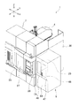
本発明の実施形態1を、図1ないし図8を参照しつつ説明する。図1及び図2に示す立形マシニングセンタ1は、ベッド2と、サドル3と、コラム4と、主軸頭5と、テーブル6と、本体カバー7と、パレット交換装置8と、側部カバー9とを備えている。なお、立形マシニングセンタ1は本発明の工作機械の一例である。
<
図2に示すようにベッド2は、平面視で前後方向(Y軸方向)に長い長方形状とされて床上に設置されている。ベッド2の上面で該ベッド2の後方端部には、上向きに起立した起立部11が設けられている。この起立部11の上面には、サドル3が、X軸ガイドレール12,12に案内されて左右方向(X軸方向)へ移動可能に設けられている。サドル3の上面には、コラム4が、Y軸ガイド部材13に案内されてY軸方向へ移動可能に設けられている。コラム4の前面には、主軸14が回転可能に支持された主軸頭5が、Z軸ガイドレール15,15に案内されて、該主軸14の軸心と平行な上下方向(Z軸方向)へ移動可能に設けられている。
As shown in FIG. 2, the
図2に示すようにテーブル6は、Z軸方向でベッド2の前方上面よりも上方で主軸14よりも下方に配置されている。加えてテーブル6は、Y軸方向でテーブル6の後方に配置された起立部11と、該Y軸方向でテーブル6の前方かつベッド2の上面の前端部に立設された支持部17とで両端支持されている。起立部11には、テーブル6をY軸方向と平行なB軸回りで揺動させるための揺動用駆動装置18が設けられており、この揺動用駆動装置18にテーブル6の後部が接続されている。一方、テーブル6の前部は、回転可能な揺動軸19を介して前記支持部17に支持されている。そして図2に示すように、揺動用駆動装置18の縦寸法よりも支持部17の縦寸法を小さくした。本実施形態では、揺動用駆動装置18を駆動することによりテーブル6を、B軸及び揺動軸19回りで揺動させることができる。なお、支持部17は本発明のテーブルの前方に配置した支持部の一例であり、揺動用駆動装置18は本発明のテーブルの後方に配置した支持部の一例である。
As shown in FIG. 2, the table 6 is disposed above the front upper surface of the
さらにテーブル6は、ワーク(図示せず。)を取り付けたパレット21(図2参照。)をテーブル6の上面に固定する固定機構(図示せず。)を有する。これに加えてテーブル6は、その上面に固定されたパレット21をA軸回りで回転させて所定の位置に割り出す割り出し用駆動装置(図示せず。)も有する。このA軸はテーブル6の回転軸を意味する。
Further, the table 6 has a fixing mechanism (not shown) for fixing the pallet 21 (see FIG. 2) to which a work (not shown) is attached to the upper surface of the table 6. In addition to this, the table 6 also has an indexing drive device (not shown) that rotates the
また図1に示す本体カバー7は、鋼板によって成形されて、下面(図1の下側)及び後面(図1の右斜め奥側)を開口させた略箱状とされている。この本体カバー7により、図2に示した起立部11を除くベッド2の前方、左右の側方及び上方が覆われている。本実施形態では、本体カバー7の内側でベッド2の前方上面の上方空間にテーブル6が配置されており、この上方空間がワークの加工空間25(図2参照。)となる。なお、ベッド2は本発明の工作機械の本体の一例である。
Further, the
この本体カバー7の前面(図1の右斜め手前側)で該前面の左右方向の中央部付近には、加工空間25(図2参照。)に面して開口部26が設けられている。そして、本体カバー7の前面には、開口部26を開閉するための開閉ドア27が、該前面の左右方向へ水平移動可能に設けられている。この開閉ドア27を左方向(図1の左斜め奥側)に水平移動させると、開口部26が開放される。立形マシニングセンタ1の使用者は、開口部26を通じてテーブル6の上面にあるワークの確認や点検を行ったり、立形マシニングセンタ1の点検等を行うことができる。さらに、本体カバー7の前面で開口部26の右側には、立形マシニングセンタ1の操作や、ワークの加工プログラムのパラメータ等を入力する操作部28が設けられている。なお、開閉ドア27は本発明の第1のドアの一例である。
An
さらに、本体カバー7の右側面7A(図1の左斜め手前側)には、本体カバー7の内部と外部とを連通させるワーク搬出入口29(図1参照。)が形成されている。このワーク搬出入口29は、後述するパレット交換装置8により、本体カバー7内のテーブル6に加工前のワークを取り付けたパレット22(図2参照。)を搬入したり、テーブル6の上面から加工済みのワークを取り付けたパレット21(図2参照。)を該パレット交換装置8側へ搬出するために用いられる。加えて、コラム4の右側部(図2の左斜め手前側)を保護するために、本体カバー7の右側面7Aの後端縁部には、該右側面7Aと同じ高さとされてコラム4の後端部を越えて本体カバー7の後方(図1の右斜め奥側)へ延びる金属製の保護板30が固着されている。
Further, a work loading / unloading port 29 (see FIG. 1) that allows communication between the inside and the outside of the
本実施形態の立形マシニングセンタ1では、上述した構成を採用したことにより、主軸頭5を、テーブル6上のパレット21に取り付けたワークに対し、互いに直交するX軸・Y軸・Z軸の方向へ相対的に移動可能とした。また、テーブル6をB軸回りで揺動可能とし、A軸回りでテーブル6上のパレット21を所定の位置に回転割り出し可能とした。よって、立形マシニングセンタ1では、例えば主軸14に工具を装着し、5軸(X軸・Y軸・Z軸・A軸・B軸)制御により前記工具とワークとの相対位置を制御して、加工空間25において前記工具により前記ワークに対し切削加工や旋削加工を行うことができる。
In the
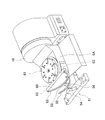
図1及び図2に示すようにパレット交換装置8は、本体カバー7の右側面7Aに隣接して配置されている。パレット交換装置8は、固定台32と、移動台33と、旋回部材34とを備えている。なお、本体カバー7の右側面7Aは本発明の本体カバーの一方の側部の一例である。
As shown in FIGS. 1 and 2, the
固定台32は、ベッド2の右側部に隣接して床上に設置されている。移動台33は、平面視で略円形とされており、モータMによって駆動されて水平移動可能とされている。この移動台33は、固定台32の上面で本体カバー7に対する接離方向(ここでは左右方向)へ延びる一対のガイドレール36,36に案内されて該接離方向へ水平移動可能に設けられている。さらに移動台33の上面には、モータ(図示せず。)によって回転駆動される回転軸37が突設されている。加えて、移動台33の上面には、回転軸37に隣接させて旋回部材34を上下動させる昇降装置38が配置されている。この昇降装置38は、上下方向に伸縮するロッド(図示せず。)を備えている。
The fixed
また旋回部材34は、平面視長方形状の金属板からなる本体部39と、本体部39の一端から外側へそれぞれ突き出して互いに対向するように設けられた一対の保持腕部40,40と、本体部39の他端から外側へそれぞれ突き出して互いに対向するように設けられた一対の保持腕部41,41とを備えている。図2に示すように、方形状の各パレット21,22の対向する二面には、外側へ突出する係止突起23が形成されている。各パレット21,22の係止突起23を保持腕部40,40の上面や保持腕部41,41の上面に係止することで、各パレット21,22を保持腕部40,40や保持腕部41,41に保持できる。図2に示すように本体部39の略中央部には、回転軸37が着脱自在に嵌合される嵌合孔42が形成されている。回転軸37を嵌合孔42に嵌合させると、旋回部材34を移動台33に支持できる。この支持状態では、旋回部材34は、本体カバー7のワーク搬出入口29(図1参照。)を挟んでテーブル6の上面と同一平面上に配置されている。回転軸37を嵌合孔42に嵌合させた状態で該回転軸37を回転駆動させると、旋回部材34を水平方向に旋回させることができる。また、後述するように、移動台33を本体カバー7への接離方向へ水平移動させると、ワーク搬出入口29を通じて、移動台33に支持された旋回部材34が、加工空間25内に進退可能となる。さらに、旋回部材34の底面に設けた凹部(図示せず。)に昇降装置38のロッドを嵌合させて該ロッドを伸縮させると、旋回部材34を、前記ロッドに支持して上下動させることができる。なお、保持腕部40,40及び保持腕部41,41は、本発明の一対の保持部の一例である。
Further, the turning
図1に示す側部カバー9は、本体カバー7と同様に鋼板によって成形されて、下面及び左側面(図1の左斜め奥側)を開放させた略箱状とされている。この側部カバー9は、本体カバー7と連続するように該本体カバー7の右側面7Aに固定されている。この側部カバー9により、パレット交換装置8が覆われている。そして側部カバー9の前面9Aの略上半分には、旋回部材34(図2参照。)に面して開口部45が設けられている。そして、前記前面9Aの略上半分には、開口部45を開閉するための両開きドア46,47が設けられている。この両開きドア46,47は、開口部45の左縁部や右縁部に設けられたヒンジ部(図示せず。)を介して該開口部45を開閉可能としている。例えば、立形マシニングセンタ1の使用者は、開口部45を通じて、保持腕部40,40及び保持腕部41,41に向けて加工前のワークを取り付けたパレット22を搬入したり、保持腕部40,40及び保持腕部41,41から加工済みのワークを取り付けたパレット21を側部カバー9の外側へ搬出できる。なお、両開きドア46,47は本発明の第2のドアの一例である。
The
次に、立形マシニングセンタ1の動作を説明する。以下では、テーブル6の上面に加工済みのワークを取り付けたパレット21(図2参照。)を載置した状態から、パレット交換装置8を動作させる例を説明する。立形マシニングセンタ1の使用者は、両開きドア46、47(図1参照。)を開操作して開口部45を開放した後に、この開口部45を通じて、図2及び図3に示す如く加工前のワークを取り付けたパレット22を、側部カバー9内に搬入して旋回部材34の保持腕部41,41に保持させる。本実施形態では両開きドア46,47を、本体カバー7と連続する側部カバー9の前面9Aに設けたことから、操作部28(図1参照。)が設けられた本体カバー7の前面と、側部カバー9内にワークを搬入する開口部45と接近させることができる。これにより、例えば立形マシニングセンタ1の使用者は、操作部28の操作と合わせて側部カバー9内へのワークの搬入作業も行い易くなる。
Next, the operation of the
パレット22を保持腕部41,41に保持させた後には、側部カバー9内で、回転軸37を回転駆動させることにより旋回部材34を反時計回りに回転させる。これにより、図4に示すように保持腕部40,40が、ワーク搬出入口29(図1参照。)を挟んで、立形マシニングセンタ1の左右方向でテーブル6上のパレット21と同一平面上で隣接するように割り出される。これに続いて図2に示すモータMを駆動させ、移動台33を、ガイドレール36,36に案内させて本体カバー7に対する接近方向へ水平移動させる。すると、移動台33に支持された旋回部材34の保持腕部40,40は、ワーク搬出入口29から加工空間25(図2参照。)に進入した後に、図5に示すようにパレット21を保持する。本実施形態ではテーブル6の揺動軸19が、加工空間25内で前記接近方向の前方において該接近方向と直交するように配置されている。このため、該接近方向に揺動軸19が設けられることがないので揺動軸19は、テーブル6に対する旋回部材34の接近を妨げない。
After the
図5に示す如く保持腕部40,40がパレット21を保持した後には、図2に示す昇降装置38のロッドを伸ばして旋回部材34の凹部に嵌合させる。この状態から、さらにロッドを所定長さ伸ばすことにより、回転軸37を嵌合孔42に嵌合させたまま旋回部材34を上昇させ、保持腕部40,40(パレット21)をテーブル6の上面から上方に所定距離だけ離して固定する。続いて、回転軸37を回転駆動させることにより加工空間25内で旋回部材34を時計回りに回転させ、保持腕部40,40に代えて、図6に示すように保持腕部41,41(パレット22)が、テーブル6の上面の上方に位置するように割り出される。これと同時に保持腕部40,40(パレット21)は、テーブル6の上面からパレット交換装置8側に位置するように割り出される。その後には、昇降装置38のロッドを縮めて旋回部材34を下降させ、パレット22をテーブル6の上面に載置すると共に、昇降装置38のロッドと旋回部材34の凹部との嵌合を解除する。このようにして、加工前のワークを取り付けたパレット22が、パレット交換装置8側からテーブル6の上面に搬送されることになる。なお、パレット22は本発明の第2のパレットの一例である。
After the holding
その次には、図2に示すモータMを駆動させて移動台33を、ガイドレール36,36に案内させて本体カバー7に対する離間方向へ水平移動させる。すると、移動台33に支持された図7に示す旋回部材34の保持腕部40,40は、ワーク搬出入口29から加工空間25の外部に退いた後に、前記離間方向に沿って側部カバー9内で開口部45(図1参照。)に面する位置まで移動する。その後には、側部カバー9内で回転軸37を回転駆動させることにより旋回部材34を時計回りに回転させ、図8に示すように保持腕部40,40(パレット21)を、開口部45と正対するように割り出す。このようにして、加工済みのワークを取り付けたパレット21が、テーブル6の上面からパレット交換装置8側に搬送されることになる。立形マシニングセンタ1の使用者は、開口部45を通じて、加工済みのワークを取り付けたパレット21を、保持腕部40,40から側部カバー9の外側へ搬出する。なお、パレット21は本発明の第1のパレットの一例である。
Next, the motor M shown in FIG. 2 is driven, and the moving table 33 is guided by the guide rails 36 and 36 and moved horizontally in the direction away from the
この他に本実施形態では、図2に示す揺動用駆動装置18の縦寸法よりも支持部17の縦寸法を小さくした。このため、例えば、立形マシニングセンタ1の使用者が、開閉ドア27(図1参照。)を水平移動させて開口部26(図1参照。)を開放した後に、この開口部26からテーブル6上のワークを確認したり点検する際に、このワークが支持部17に隠れて見え難くなることを抑制できる。
In addition to this, in this embodiment, the vertical dimension of the
<実施形態1の効果>
本実施形態の立形マシニングセンタ1では、パレット交換装置8に備えられた旋回部材34は、加工空間25内における水平方向への旋回動作によって、加工済みのワークを取り付けたパレット21と、加工前のワークを取り付けたパレット22とを、テーブル6とパレット交換装置8側との間で搬送できる。これに加えて旋回部材34は、本体カバー7に対する接離方向への水平移動によって、前記パレット21と前記パレット22とを、テーブル6とパレット交換装置8側との間で搬送できる。よって、旋回部材34に、旋回動作と本体カバー7に対する接離方向への水平移動動作という複数の動作をさせることができるため、該旋回部材34を旋回動作させる装置と該旋回部材34を本体カバー7に対する接離方向へ水平移動動作させる装置とを別々に設けた上で、これらの装置を同調させる装置を設ける必要がない。これにより、パレット交換装置8の構造を簡素化できる。
さらに、旋回部材34によって複数の動作(前記旋回動作及び前記水平移動動作)をさせることができれば、該旋回動作させる装置と該水平移動動作させる装置とを別々に設けて、両装置の間でパレット21,22を受け渡す時間(受け渡し時間)が不要になる。これにより、テーブル6とパレット交換装置8との間でパレット21とパレット22とを交換する際には、前記受け渡し時間が累積されることがない結果、両パレット21,22の交換に要する時間を短縮できる。
<Effect of
In the
Further, if a plurality of actions (the turning action and the horizontal movement action) can be performed by the turning
また、立形マシニングセンタ1の使用者は、側部カバー9の前面9Aの両開きドア46,47を開操作して開口部45を開放すると、この開口部45を通じて、加工済みのワークを取り付けたパレット21を、保持腕部40,40から側部カバー9の外側へ搬出したり、開口部45を通じて、加工前のワークを取り付けたパレット22を、側部カバー9内に搬入して旋回部材34の保持腕部41,41に保持させることができる。したがって、立形マシニングセンタ1の本体カバー7の前面と、側部カバー9内にワークを搬出入する開口部45とを接近させることができる。これにより、例えば立形マシニングセンタ1の使用者は、本体カバー7の前面の操作部28の操作と合わせて側部カバー9内へのワークの搬出入作業も行い易くなる。
Further, when the user of the
さらに加工空間25内では、本体カバー7に対する旋回部材34の水平移動方向にテーブル6の揺動軸19が設けられることがない。このため、揺動軸19は、テーブル6に対する旋回部材34の接近を妨げない。
Further, in the
加えて、揺動用駆動装置18の縦寸法よりも支持部17の縦寸法を小さくした。このため、例えば立形マシニングセンタ1の使用者が、本体カバー7の開閉ドア27を水平移動させて開口部26を開放した後に、この開口部26からテーブル6上のワークを確認したり点検する際に、このワークが支持部17に隠れて見え難くなることを抑制できる。これにより、テーブル6上のワークの確認や点検が容易になる。
In addition, the vertical dimension of the
<実施形態2>
本発明の実施形態2を、図9ないし図14を参照しつつ説明する。ここでは、実施形態1と同一の構成は同一の符号を付しその説明を省略する。この立形マシニングセンタ1Aも、図示を省略した本体カバー7及び側部カバー9を備えている。図9に示すように起立部11の前面には、サドル3Aが、X軸ガイドレール12A,12Aに案内されてX軸方向へ移動可能に設けられている。サドル3Aの前面には、主軸頭5が、Z軸ガイドレール15A,15Aに案内されて、主軸14の軸心と平行なZ軸方向へ移動可能に設けられている。
<
A second embodiment of the present invention will be described with reference to FIGS. Here, the same configurations as those of the first embodiment are denoted by the same reference numerals, and the description thereof is omitted. The
ベッド2の上面には、図9及び図11に示すスライドテーブル50が、Y軸ガイドレール13A,13A(図10参照。)に案内されて、ベッド2の前後方向(Y軸方向)へ移動可能に設けられている。このスライドテーブル50の後端部(図9の右斜め奥側)には揺動用駆動装置18が立設され、スライドテーブル50の前端部には、テーブル6Aの前部を揺動可能に支持する支持部51が立設されている。
9 and 11 is guided on Y-
図12に示すようにテーブル6Aの前面(図12の右斜め手前側)には、上面を平坦にした半円板60が固定されている。この半円板60の上面は、テーブル6Aの上面に設けられたワークの固定機構61よりも下方に配置されている。そして半円板60の前面には、B軸(図11参照。)の軸心を中心とする半円弧状とされた固定レール62(図12参照。)が取り付けられている。この固定レール62には、該固定レール62の上面に開口した凹状のレール溝(図示せず。)が、前記上面の一端部から他端部に亘って形成されている。レール溝の両端を閉塞することにより、レール溝の両端部には立壁63(図12参照。)がそれぞれ形成されている。なお、固定レール62は本発明の第1のレール部材の一例である。
As shown in FIG. 12, a
一方図9及び図12に示すように支持部51は、可動レール52と、係合部材53と、可動レール支持部材54とを備えている。可動レール52は、B軸(図11参照。)の軸心を中心とする円弧状とされており、正面視で円弧状とされた部材(円弧状部材55、図9ないし図11参照。)の前面に固定されている。また、この円弧状部材55の後面には係合部材53が固定されており、この係合部材53は、前記固定レール62のレール溝に嵌め入れられて摺動可能に係合する。また可動レール支持部材54は、スライドテーブル50の前端部に立設されている。この可動レール支持部材54の後面(図12の右斜め奥側)にはガイド部材56が突設されている。このガイド部材56(図9及び図12参照。)には、B軸の軸心を中心とする円弧状で、ガイド部材56における可動レール支持部材54側とは反対側の面及びガイド部材56の左右の側面に開口する凹状のガイド溝57(図11参照。)が形成されている。そして可動レール52は、ガイド溝57に摺動可能に嵌め入れられている。図9及び図10に示すように、テーブル6AがB軸回りで揺動する前には可動レール52は、ガイド溝57に嵌め入れられて、テーブル6A上の固定機構61よりも下方に配置されている。後述するように可動レール52は、ガイド溝57に案内されてB軸回りで揺動可能とされている。本実施形態では、図11に示すように、揺動用駆動装置18の縦寸法よりも支持部51の縦寸法を小さくした。なお、支持部51は本発明のテーブルの前方に配置した支持部の一例である。
On the other hand, as shown in FIGS. 9 and 12, the
次に、テーブル6AをB軸回りで揺動させる動作を説明する。図9及び図10に示すようにテーブル6Aの上面を上向き水平に割り出した位置から揺動用駆動装置18を正方向に揺動回転させる。すると、図9,10及び図13,14に示すように、テーブル6Aの前面の半円板60に取り付けられた固定レール62が、係合部材53と係合しながらB軸(図11参照。)回りで正方向に揺動回転する。これ伴ってテーブル6Aも、前記B軸回りで正方向に揺動回転する。このとき、固定レール62はテーブル6Aの前面から該テーブル6Aの上面を越えて突出することがない。よって、固定機構61にワークを取り付けたパレットを固定している場合でも、このワークが固定レール62に隠れることがない。このため、立形マシニングセンタ1Aの使用者は、本体カバー7の開口部26(図1参照。)からテーブル6A上のワークの確認や点検を容易に行うことができる。なお、B軸は本発明の揺動軸の一例である。
Next, the operation of swinging the table 6A around the B axis will be described. As shown in FIGS. 9 and 10, the
固定レール62が正方向への揺動回転を続け、図14に示すような固定レール62の一方の立壁63が係合部材53に当接した後も、固定レール62が前記揺動回転を続けると、該立壁63が係合部材53に係止され、この立壁63は、係合部材53及び円弧状部材55と共に可動レール52に対しこれらを前記正方向に押し出す力を与える。この力を受けた可動レール52は、ガイド溝57(図11参照。)に案内され、固定レール62と共に前記正方向へ揺動回転することになる。このようにしたことで、テーブル6Aは、固定レール62の正方向への揺動範囲によって規定される揺動可能角度に加えて、可動レール52の正方向の揺動範囲によって規定される揺動可能角度まで該正方向に揺動することになる。なお、可動レール52は本発明の第2のレール部材の一例であり、立壁63は本発明の係止部の一例である。
The fixed
一方、図9及び図10に示す状態から揺動用駆動装置18を逆方向に揺動回転させた場合にも、固定レール62の他方の立壁63(図12の左斜め奥側の立壁63)が、可動レール52を前記逆方向に押し出す力を与える。このようにしたことで、テーブル6Aは、固定レール62の逆方向への揺動範囲によって規定される揺動可能角度に加えて、可動レール52の逆方向の揺動範囲によって規定される揺動可能角度まで該逆方向に揺動することになる。
On the other hand, when the
<実施形態2の効果>
本実施形態の立形マシニングセンタ1Aでは、テーブル6AがB軸回りで揺動を開始する前や揺動する際には、固定レール62がテーブル6Aの前面から該テーブル6Aの上面を越えて突出することがない。よって、テーブル6A上に固定されたワークが固定レール62に隠れることがないため、該ワークの確認や点検が容易になる。
<Effect of
In the
また、テーブル6Aは、固定レール62の正逆方向への揺動範囲によって規定される揺動可能角度に加えて、可動レール52の正逆方向の揺動範囲によって規定される揺動可能角度まで揺動させることが可能になる。したがって、固定レール62の揺動に対応させてテーブル6Aを揺動させる場合のみと比較して、テーブル6Aの揺動可能角度を大きくすることができる。
Further, the table 6A has a swingable angle defined by the swing range of the
本発明は、上述した実施形態に限定されるものではなく発明の趣旨を逸脱しない範囲内において構成の一部を適宜変更して実施できる。上述した実施形態1とは異なり、揺動用駆動装置18を設けずに、テーブル6の後部を揺動軸を介して起立部11に支持した上で、該揺動軸を回転送りするためのB軸モータを起立部11に設けてもよい。この起立部11は本発明の支持部の一例である。
The present invention is not limited to the above-described embodiment, and can be implemented by appropriately changing a part of the configuration without departing from the spirit of the invention. Unlike the above-described first embodiment, B is provided for supporting the rear portion of the table 6 on the
また上述した実施形態1,2とは異なり,移動台33に代えてテーブル6,6Aを、ワーク搬出入口29を通じてパレット交換装置8側に進退可能に設け、テーブル6,6Aを、ワーク搬出入口29を通じてパレット交換装置8側に進入させた後に、側部カバー9内(パレット交換装置8側)において、旋回部材34の旋回動作をさせることにより、加工済みのワークを取り付けたパレット21と、加工前のワークを取り付けたパレット22とを、テーブル6,6Aとパレット交換装置8との間で搬送してもよい。このようにすれば、旋回部材34は、本体カバー7に対する接離方向への移動動作を行わなくても、側部カバー9内において旋回動作を行うことにより、加工済みのワークを取り付けたパレット21と、加工前のワークを取り付けたパレット22とを、テーブル6,6Aとパレット交換装置8との間で搬送できる。加えて、上述した実施形態1,2とは異なり、旋回部材34を、ワーク搬出入口29を通じて加工空間25内に進退させることと、テーブル6,6Aを、ワーク搬出入口29を通じてパレット交換装置8側に進退させることとの双方を可能にしてもよい。
Unlike the above-described first and second embodiments, the tables 6 and 6A are provided in the
さらに上述した実施形態1,2とは異なり、移動台33の上面に昇降装置38を設けずに、テーブル6,6Aの上面より上方の平面上において旋回部材34を水平回転可能に設けた上で、テーブル6,6Aの上面に、テーブル6,6Aの上面より上方に位置する旋回部材34の保持腕部40,40や保持腕部41,41に対してテーブル6,6Aの上面に載置されるパレットを昇降可能な昇降装置を設けてもよい。加えて、上述した実施形態2とは異なり、可動レール52の両端の上面に、上方へ突出する脱落防止片をそれぞれ設け、可動レール52の揺動が揺動範囲の限界まで達したときに、脱落防止片がガイド部材56に係止されるようにしてもよい。これにより、可動レール52がガイド部材56のガイド溝57から脱落することを防止できる。また、上述した実施形態1,2とは異なり、パレット交換装置8を、側部カバー9で覆わずに本体カバー7の右側面7Aに隣接して配置し、パレット交換装置8側で、旋回部材34を水平方向へ旋回動作させることにより、保持腕部40,40あるいは保持腕部41,41を、パレット交換装置8の前方に向けた位置に割り出し可能としてもよい。このようにすれば、立形マシニングセンタ1の使用者は、パレット交換装置8の前方から、保持腕部40,40に保持された加工済みのワークを取り付けたパレット21をパレット交換装置8の外側へ搬出したり、パレット交換装置8の前方から保持腕部41,41に向けて、加工前のワークを取り付けたパレット22を搬入できる。これにより、立形マシニングセンタ1の使用者が、パレット交換装置8に対するワークの搬出入作業を行い易くなる。さらに上述した実施形態1,2とは異なり、側部カバーは、本体カバー7の右側面7Aとの間に隙間をおいて配置してパレット交換装置8を覆うものであってもよい。
Further, unlike the first and second embodiments described above, the
1,1A・・立形マシニングセンタ、2・・ベッド、6,6A・・テーブル、7・・本体カバー、7A・・本体カバーの右側面、8・・パレット交換装置、9・・側部カバー、17・・支持部、18・・揺動用駆動装置、19・・揺動軸、21,22・・パレット、25・・加工空間、27・・開閉ドア、29・・ワーク搬出入口、34・・旋回部材、40,41・・保持腕部、46,47・・両開きドア、52・・可動レール、53・・係合部材、62・・固定レール、63・・立壁。 1, 1A ··· Vertical machining center, 2 ·· Bed, 6, 6A ·· Table, 7 ·· Main body cover, 7A ·· Right side of main body cover, 8 ·· Pallet changer, 9 ·· Side cover, 17 .. Support part, 18 .. Oscillating drive device, 19 .. Oscillating shaft, 21, 22 .. Pallet, 25 .. Processing space, 27 .. Opening / closing door, 29. Rotating member, 40, 41 ... Holding arm, 46, 47 ... Double door, 52 ... Movable rail, 53 ... Engaging member, 62 ... Fixed rail, 63 ... Standing wall.
Claims (6)
前記パレット交換装置は、両端部に前記第1のパレットと前記第2のパレットとをそれぞれ保持可能な一対の保持部が設けられて、水平方向に旋回自在な旋回部材を備え、
前記旋回部材を、前記本体カバーに設けられたワーク搬出入口を通じて前記加工空間内に進退させることを可能にして、
前記旋回部材を、前記ワーク搬出入口を通じて前記加工空間内に進入させた後に、前記加工空間内において前記旋回部材を前記水平方向に旋回させることにより、前記加工空間内において、一方の前記保持部に保持した前記第1のパレットを前記テーブルの上面から前記パレット交換装置に搬送すると共に、他方の前記保持部に保持した前記第2のパレットを前記パレット交換装置から前記テーブルの上面に搬送することを可能とする一方、
前記パレット交換装置側で、前記旋回部材を前記水平方向に旋回させることにより、前記一方の保持部あるいは前記他方の保持部を、前記パレット交換装置の前方に向けた位置に割り出し可能としたことを特徴とする工作機械。 In the machining space of the workpiece provided in the machine tool body, the workpiece can be machined by the tool by relatively moving a table and a tool for fixing the pallet to which the workpiece is attached to the upper surface, and the machining space is The main body cover is provided with a first door that opens and closes the front surface of the main body cover so as to face the processing space, and is adjacent to one side of the main body cover, and the table A machine tool having a pallet exchanging device for exchanging a first pallet to which a processed workpiece fixed to the upper surface of the workpiece is attached and a second pallet to which a workpiece before processing is attached,
The pallet exchanging device is provided with a pair of holding parts capable of holding the first pallet and the second pallet at both ends, respectively, and provided with a turning member that can turn in the horizontal direction.
Said pivot member, make it possible to advance and retreat in the in the working space through the workpiece transfer port provided in the body cover,
Said pivot member, after allowed to enter into the working space through the workpiece transfer port, by pivoting said pivot member in said working space in the horizontal direction, Oite into the processing space, one of the holding The first pallet held in the section is transported from the upper surface of the table to the pallet exchanging apparatus, and the second pallet held in the other holding section is transported from the pallet exchanging apparatus to the upper surface of the table. While allowing
The one holding part or the other holding part can be indexed to a position facing the front of the pallet changing device by turning the turning member in the horizontal direction on the pallet changing device side. A featured machine tool.
前記揺動軸の揺動によって、前記第1のレール部材が前記係合部材と係合しながら前記揺動軸回りで揺動することに伴って前記テーブルが該揺動軸回りで揺動することを特徴する請求項4に記載の工作機械。 A first rail member having an arc shape centered on the axis of the swing shaft is fixed to the front surface of the table below the upper surface of the table, and on the support portion disposed in the front, An engagement member that engages with the first rail member is provided,
The table swings around the swing axis as the first rail member swings around the swing shaft while engaging the engaging member by swinging of the swing shaft. The machine tool according to claim 4 , wherein:
前記第1のレール部材には、前記係合部材に係止されて、該第1のレール部材が前記揺動軸回りで揺動することに伴って前記第2のレール部材を前記揺動軸回りで揺動させる係止部を設けたことを特徴とする請求項5に記載の工作機械。 A second support portion is located below the upper surface of the table before swinging on the support portion disposed in front of the table, and the engagement member is fixed to form a circular arc centered on the axis of the swing shaft. The rail member is supported so as to be swingable around the swing shaft,
The first rail member is locked to the engaging member, and the second rail member is moved to the swing shaft as the first rail member swings around the swing shaft. The machine tool according to claim 5 , further comprising a locking portion that swings around.
Priority Applications (8)
| Application Number | Priority Date | Filing Date | Title |
|---|---|---|---|
| JP2014085769A JP6403978B2 (en) | 2014-04-17 | 2014-04-17 | Machine Tools |
| US14/641,839 US20150298271A1 (en) | 2014-04-17 | 2015-03-09 | Machine tool |
| US14/643,104 US20150298272A1 (en) | 2014-04-17 | 2015-03-10 | Machine tool |
| TW104110437A TWI652133B (en) | 2014-04-17 | 2015-03-31 | Machine tool |
| CH00515/15A CH709579B1 (en) | 2014-04-17 | 2015-04-14 | Machine tool. |
| DE102015206914.1A DE102015206914A1 (en) | 2014-04-17 | 2015-04-16 | machine tool |
| CN201510184501.4A CN105014390A (en) | 2014-04-17 | 2015-04-17 | Machine tool |
| KR1020150054198A KR101878857B1 (en) | 2014-04-17 | 2015-04-17 | Machine tool |
Applications Claiming Priority (1)
| Application Number | Priority Date | Filing Date | Title |
|---|---|---|---|
| JP2014085769A JP6403978B2 (en) | 2014-04-17 | 2014-04-17 | Machine Tools |
Publications (3)
| Publication Number | Publication Date |
|---|---|
| JP2015205356A JP2015205356A (en) | 2015-11-19 |
| JP2015205356A5 JP2015205356A5 (en) | 2016-12-22 |
| JP6403978B2 true JP6403978B2 (en) | 2018-10-10 |
Family
ID=54250111
Family Applications (1)
| Application Number | Title | Priority Date | Filing Date |
|---|---|---|---|
| JP2014085769A Active JP6403978B2 (en) | 2014-04-17 | 2014-04-17 | Machine Tools |
Country Status (7)
| Country | Link |
|---|---|
| US (2) | US20150298271A1 (en) |
| JP (1) | JP6403978B2 (en) |
| KR (1) | KR101878857B1 (en) |
| CN (1) | CN105014390A (en) |
| CH (1) | CH709579B1 (en) |
| DE (1) | DE102015206914A1 (en) |
| TW (1) | TWI652133B (en) |
Families Citing this family (24)
| Publication number | Priority date | Publication date | Assignee | Title |
|---|---|---|---|---|
| USD788196S1 (en) * | 2014-09-12 | 2017-05-30 | Pocket NC Company | Multi-axis machine |
| US20160074946A1 (en) * | 2014-09-12 | 2016-03-17 | Pocket NC Company | Multi-axis machining systems and related methods |
| DE202016101742U1 (en) * | 2016-04-01 | 2017-07-05 | Thorsten Lasch | Manipulator unit and pallet changing system |
| FR3056932B1 (en) * | 2016-10-04 | 2018-11-02 | Comau France | MACHINE TOOL WITH VERTICAL PIN |
| CN206367803U (en) * | 2016-11-01 | 2017-08-01 | 合肥鑫晟光电科技有限公司 | Transferred product device |
| US20180169780A1 (en) * | 2016-12-19 | 2018-06-21 | Anvil International, Llc | Cleanline threader |
| KR101891576B1 (en) * | 2017-04-26 | 2018-08-28 | (주)유지인트 | Vertical machining center with automatic pallet changer |
| JP6445084B2 (en) * | 2017-05-18 | 2018-12-26 | ファナック株式会社 | Machine Tools |
| DE102017209845A1 (en) * | 2017-06-12 | 2018-12-13 | Deckel Maho Pfronten Gmbh | Machine tool for machining a workpiece by means of a tool |
| CN107298283A (en) * | 2017-08-08 | 2017-10-27 | 惠科股份有限公司 | Display panel checks equipment and display panel testing method |
| JP6944529B2 (en) * | 2017-09-13 | 2021-10-06 | 株式会社牧野フライス製作所 | Machine Tools |
| JP6298569B1 (en) | 2017-10-20 | 2018-03-20 | 株式会社松浦機械製作所 | Pallet changer |
| JP6298570B1 (en) | 2017-10-20 | 2018-03-20 | 株式会社松浦機械製作所 | Pallet changer |
| USD861750S1 (en) * | 2018-05-02 | 2019-10-01 | Pocket NC Company | Multi-axis machine |
| CN108655804A (en) * | 2018-06-13 | 2018-10-16 | 上海交大智邦科技有限公司 | A kind of full-automatic fast switching frock chucking appliance system |
| JP1632017S (en) * | 2018-10-26 | 2019-05-20 | ||
| USD933111S1 (en) | 2018-10-26 | 2021-10-12 | Mitsubishi Electric Corporation | Laser processing machine |
| USD938501S1 (en) * | 2019-01-11 | 2021-12-14 | Doosan Machine Tools Co., Ltd. | Machine center |
| CN110605607B (en) * | 2019-09-27 | 2024-04-16 | 科德数控股份有限公司 | Automatic feeding and discharging processing system |
| CN114871852B (en) * | 2020-06-11 | 2023-10-20 | 杭州友佳精密机械有限公司 | Multi-spindle machining center and system with micro-motion compensation function |
| USD923670S1 (en) * | 2020-06-22 | 2021-06-29 | Doosan Machine Tools Co., Ltd. | Machine center |
| DE102020133542B4 (en) * | 2020-12-15 | 2022-10-13 | Deckel Maho Pfronten Gmbh | Handling system and handling device for handling workpiece pallets and machine tool with handling system |
| DE102021113890A1 (en) * | 2021-05-28 | 2022-12-01 | Chiron Group Se | Production system and plant for metal-cutting production |
| CN113618424A (en) * | 2021-09-07 | 2021-11-09 | 苏州科技大学 | Special fixture for processing machine tool box body component |
Family Cites Families (21)
| Publication number | Priority date | Publication date | Assignee | Title |
|---|---|---|---|---|
| US5265497A (en) * | 1992-09-08 | 1993-11-30 | Cincinnati Milacron Inc. | Guard for operator access station |
| JP2559815Y2 (en) * | 1993-07-19 | 1998-01-19 | オークマ株式会社 | Lifting door opening and closing mechanism |
| TW404289U (en) | 1998-11-04 | 2000-09-01 | Ind Tech Res Inst | Automatic pallet exchange device |
| JP2001025925A (en) * | 1999-07-14 | 2001-01-30 | Toumei Engineering:Kk | Angle indexing device |
| JP2001062655A (en) * | 1999-08-20 | 2001-03-13 | Mori Seiki Co Ltd | Pallet oscillating device and machine tool having this device |
| TW454616U (en) | 2000-06-14 | 2001-09-11 | Safeway Machinery Industry Cor | Universal tilting rotary table with V-shape grooves |
| JP4538292B2 (en) * | 2003-10-17 | 2010-09-08 | 株式会社三共製作所 | Tilting rotary table device |
| JP4732734B2 (en) * | 2004-08-31 | 2011-07-27 | ユキワ精工株式会社 | Rotary table device |
| US7357769B2 (en) * | 2005-05-25 | 2008-04-15 | Mori Seiki Co., Ltd. | Machine tool |
| JP4342474B2 (en) * | 2005-05-25 | 2009-10-14 | 株式会社森精機製作所 | Machine Tools |
| PL1747843T5 (en) * | 2005-07-30 | 2012-06-29 | Mikron Agie Charmilles Ag | Machine-tool with a device for changing workpieces |
| EP1754568A1 (en) * | 2005-08-19 | 2007-02-21 | Mikron Agie Charmilles AG | Machine tool with an automatic cover in the roof |
| JP2007152506A (en) * | 2005-12-06 | 2007-06-21 | Mitsui Seiki Kogyo Co Ltd | Arrangement structure for pallet changer and operator in vertical machining center |
| JP4720523B2 (en) | 2006-01-30 | 2011-07-13 | ブラザー工業株式会社 | Machine Tools |
| JP4970848B2 (en) * | 2006-05-30 | 2012-07-11 | オークマ株式会社 | Space securing method for machine tools |
| JP5171111B2 (en) * | 2007-05-29 | 2013-03-27 | オークマ株式会社 | Pallet changer |
| CN102046327B (en) * | 2008-05-27 | 2015-03-04 | 株式会社牧野铣床制作所 | Machine tool |
| TWI404289B (en) * | 2010-02-26 | 2013-08-01 | Univ Nat Taiwan | Low parasitic capacitance electrostatic discharge protection circuit |
| CN102601713A (en) * | 2012-04-18 | 2012-07-25 | 安徽力成机械装备有限公司 | Double-station CNC (computer numerical control) vertical ball cage arc raceway groove and ball hole grinding machine |
| US9144870B2 (en) * | 2012-09-07 | 2015-09-29 | Midaco Corporation | Rotary pallet pool |
| KR101416386B1 (en) * | 2012-12-17 | 2014-07-08 | 현대자동차 주식회사 | Spindle jig and Auto pallet changable machining center having the same |
-
2014
- 2014-04-17 JP JP2014085769A patent/JP6403978B2/en active Active
-
2015
- 2015-03-09 US US14/641,839 patent/US20150298271A1/en not_active Abandoned
- 2015-03-10 US US14/643,104 patent/US20150298272A1/en not_active Abandoned
- 2015-03-31 TW TW104110437A patent/TWI652133B/en not_active IP Right Cessation
- 2015-04-14 CH CH00515/15A patent/CH709579B1/en not_active IP Right Cessation
- 2015-04-16 DE DE102015206914.1A patent/DE102015206914A1/en not_active Withdrawn
- 2015-04-17 CN CN201510184501.4A patent/CN105014390A/en active Pending
- 2015-04-17 KR KR1020150054198A patent/KR101878857B1/en active IP Right Grant
Also Published As
| Publication number | Publication date |
|---|---|
| KR101878857B1 (en) | 2018-07-16 |
| CH709579B1 (en) | 2019-01-31 |
| US20150298271A1 (en) | 2015-10-22 |
| TWI652133B (en) | 2019-03-01 |
| DE102015206914A1 (en) | 2015-10-22 |
| JP2015205356A (en) | 2015-11-19 |
| CH709579A2 (en) | 2015-10-30 |
| US20150298272A1 (en) | 2015-10-22 |
| CN105014390A (en) | 2015-11-04 |
| KR20150120313A (en) | 2015-10-27 |
| TW201544228A (en) | 2015-12-01 |
Similar Documents
| Publication | Publication Date | Title |
|---|---|---|
| JP6403978B2 (en) | Machine Tools | |
| JP4970848B2 (en) | Space securing method for machine tools | |
| JP4901884B2 (en) | Machine Tools | |
| JP2015205356A5 (en) | ||
| JP2010036285A (en) | Robot system using robot to load and unload workpiece into and from machine tool | |
| WO2017212945A1 (en) | Pallet conveyance device | |
| JP6263607B2 (en) | Machine Tools | |
| JP6233720B2 (en) | Machine tool with tool spindle and work manipulator | |
| JP6356014B2 (en) | Gear processing machine | |
| WO2014057834A1 (en) | Machine tool | |
| JP5029223B2 (en) | Machine tool with partition plate | |
| JP6424028B2 (en) | Machine tool layout | |
| JP2009208202A (en) | Pallet exchanger | |
| JP2008296294A (en) | Pallet exchanger | |
| JP5732855B2 (en) | Work transfer device | |
| JP2001246528A (en) | Working system | |
| JP2009050976A (en) | Machine tool with loader | |
| JP6054127B2 (en) | Machine Tools | |
| JP6656262B2 (en) | Machining system | |
| JP2016165774A (en) | Machine tool | |
| JP6637989B2 (en) | Machining system | |
| JP6165550B2 (en) | Machine tool and processing line provided with a plurality of machine tools | |
| JP2014065131A (en) | Machine tool system | |
| JP7041747B2 (en) | Work automatic carrier | |
| JP2018069437A (en) | Machine tool and machine tool system |
Legal Events
| Date | Code | Title | Description |
|---|---|---|---|
| A521 | Written amendment |
Free format text: JAPANESE INTERMEDIATE CODE: A523 Effective date: 20161102 |
|
| A621 | Written request for application examination |
Free format text: JAPANESE INTERMEDIATE CODE: A621 Effective date: 20161102 |
|
| A977 | Report on retrieval |
Free format text: JAPANESE INTERMEDIATE CODE: A971007 Effective date: 20170922 |
|
| A131 | Notification of reasons for refusal |
Free format text: JAPANESE INTERMEDIATE CODE: A131 Effective date: 20171031 |
|
| A521 | Written amendment |
Free format text: JAPANESE INTERMEDIATE CODE: A523 Effective date: 20171211 |
|
| A131 | Notification of reasons for refusal |
Free format text: JAPANESE INTERMEDIATE CODE: A131 Effective date: 20180605 |
|
| A521 | Written amendment |
Free format text: JAPANESE INTERMEDIATE CODE: A523 Effective date: 20180803 |
|
| TRDD | Decision of grant or rejection written | ||
| A01 | Written decision to grant a patent or to grant a registration (utility model) |
Free format text: JAPANESE INTERMEDIATE CODE: A01 Effective date: 20180821 |
|
| A61 | First payment of annual fees (during grant procedure) |
Free format text: JAPANESE INTERMEDIATE CODE: A61 Effective date: 20180912 |
|
| R150 | Certificate of patent or registration of utility model |
Ref document number: 6403978 Country of ref document: JP Free format text: JAPANESE INTERMEDIATE CODE: R150 |