JP6401937B2 - Working scaffold and installation method - Google Patents
Working scaffold and installation method Download PDFInfo
- Publication number
- JP6401937B2 JP6401937B2 JP2014115796A JP2014115796A JP6401937B2 JP 6401937 B2 JP6401937 B2 JP 6401937B2 JP 2014115796 A JP2014115796 A JP 2014115796A JP 2014115796 A JP2014115796 A JP 2014115796A JP 6401937 B2 JP6401937 B2 JP 6401937B2
- Authority
- JP
- Japan
- Prior art keywords
- floating
- scaffold
- work
- connecting member
- working
- Prior art date
- Legal status (The legal status is an assumption and is not a legal conclusion. Google has not performed a legal analysis and makes no representation as to the accuracy of the status listed.)
- Active
Links
Images


Description
本発明は、桟橋、橋梁あるいは岸壁施設等の水域構造物の下面の点検・補修の際に使用する作業用足場及びその設置方法に関するものである。 The present invention relates to a work scaffold used when inspecting and repairing a lower surface of a water structure such as a pier, a bridge, or a quay facility, and an installation method thereof.
水域構造物、例えば桟橋の下面は、海水の影響によって劣化しやすいため、点検・補修作業が定期的に、また必要に応じて追加して行われる。
このような桟橋下面の点検・補修作業は、桟橋の下方に作業用足場を設置して行われるが、従来、この種の作業用足場としては特許文献1に記載の足場が開発されていた。
これは、足場部材と、桟橋支持用の複数の支持杭中、特定の支持杭の水面下に取り付けられる固定支持部材とを備え、足場部材の所定部位は固定支持部材に固定支持され、足場部材には、足場部材を水中に沈設する沈設手段と足場部材を水面に浮設する浮設手段とを設けてなるものである。
Since the underwater structure, for example, the lower surface of the pier is likely to deteriorate due to the influence of seawater, inspection and repair work is performed regularly and additionally as necessary.
Such inspection / repair work on the lower surface of the pier is performed by installing a work scaffold below the pier. Conventionally, a scaffold described in
This includes a scaffold member and a fixed support member attached below the water surface of a specific support pile among a plurality of support piles for supporting a pier, and a predetermined part of the scaffold member is fixedly supported by the fixed support member. Is provided with a setting means for setting the scaffold member in water and a floating means for floating the scaffold member on the water surface.
しかしながら上記従来技術では、桟橋の下方における組立・設置(施工)作業が多く、設置・撤去に時間がかかるため、船舶係留日程に支障を来し、また、台風等による強風・高波浪(荒天)時に足場が破損する虞があった。
このため、船舶係留時を避けた作業日程を調整する必要があり、また、台風等による荒天を予測して事前の撤去作業を行うことが一般的となっていた。しかし、事前の撤去作業を行う場合でも、荒天への急変によって足場の破損事故が頻繁に発生しているのが実情であった。
すなわち、船舶の離接岸が頻繁な桟橋や係留が常態化している桟橋では、いわゆる大型連休等、休日が長く続く時期(連休時)まで点検・補修作業が行えないことが少なくない。
また、荒天を予測して事前の撤去作業を行う場合に、その事前の予測に対して、荒天が早く到来すると足場の破損事故が生じ、遅く到来すると、換言すれば撤去が早すぎると、結果的に作業の進捗を妨げることになる。
However, in the above prior art, there are many assembly / installation (construction) operations under the jetty, and it takes time to install / remove, which hinders the ship mooring schedule, and strong winds and high waves due to typhoons (stormy weather) At times, the scaffold could be damaged.
For this reason, it is necessary to adjust the work schedule while avoiding mooring of the ship, and it is common to perform preliminary removal work by predicting stormy weather due to typhoons and the like. However, even when the removal work was performed in advance, the actual situation was that scaffolding accidents frequently occurred due to sudden changes to stormy weather.
In other words, on piers where ships are frequently detached and moored, and piers where mooring has become normal, inspection and repair work often cannot be performed until a long holiday (such as during consecutive holidays) such as a large holiday.
In addition, when stormy weather is predicted and removal work is performed in advance, if the stormy weather arrives early, a scaffolding accident will occur, and if it arrives late, in other words, if removal is too early, the result will be Will hinder the progress of work.
本発明は、上記のような実情に鑑みなされたもので、短時間での設置・撤去が可能であって、台風到来等による荒天の直前でも撤去が可能となるため、荒天による破損事故が著しく減少し、また、点検・補修作業日程の調整が容易となり、作業の進捗を早めて点検・補修作業の全工程の時間を短縮でき、したがってまた、大型連休等、連休時まで待つことなく点検・補修作業が行える作業用足場及びその設置方法を提供することを課題とする。 The present invention has been made in view of the above circumstances, and can be installed and removed in a short time, and can be removed just before stormy weather due to the arrival of a typhoon, etc. In addition, the inspection / repair work schedule can be easily adjusted, and the progress of the work can be accelerated to shorten the time required for the entire inspection / repair work. It is an object of the present invention to provide a work scaffold capable of repair work and a method for installing the work scaffold.
上記課題を達成するために、請求項1に記載の発明は、中空箱状をなし前後部及び左右部の形状が各々対称に形成されたアルミニウム合金製の浮体ブロックを、前後方向に複数個着脱自在に連結すると共に、該浮体ブロックを、左右方向に着脱自在の連結材を介して複数個連結してなる作業用足場本体と、この作業用足場本体の上面の外周側に着脱自在に設けられる手すりと、前記左右方向に位置する浮体ブロック相互間の上部開口を塞ぐように着脱自在に設けられる渡り廊下と、を具備する作業用足場を水域構造物の下方に設置する作業用足場の設置方法であって、前記作業用足場を地上で組み立てる作業用足場組立工程と、組み立てられた作業用足場を吊り上げて水面に降ろし浮かべる作業用足場吊上げ降ろし工程と、水面に浮かべた作業用足場を前記水域構造物の下方位置に水面上を移動させる作業用足場移動工程と、移動させた作業用足場を前記水域構造物の下面から所定間隔置いた高さまで前記水面から吊上げ浮上させる作業用足場吊上げ浮上工程と、吊り上げ浮上された作業用足場に下端を支持させた伸縮パイプの上端を伸長させて前記水域構造物の下面に圧接させた状態でその長さを固定する作業用足場揺れ止め固定工程と、を含むことを特徴とする。
請求項2に記載の発明は、請求項1に記載の発明において、前記作業用足場組立工程においては、浮体ブロックを、前後方向に複数個着脱自在に連結すると共に、該浮体ブロックを、左右方向に着脱自在の連結材を介して複数個連結して作業用足場本体を組み立て、この組み立てられた作業用足場本体の上面の外周側に着脱自在に手すりを設けると共に、左右方向に位置する浮体ブロック相互間の上部開口を塞ぐように着脱自在に渡り廊下を設けることを特徴とする。
請求項3に記載の発明は、請求項1または2に記載の発明において、前記作業用足場組立工程においては、前記浮体ブロックと前記連結材とをボルト締め又はピン止めにより連結することを特徴とする。
請求項4に記載の発明は、請求項1〜3のうちのいずれか1の項に記載の発明において、前記連結材は、前記浮体ブロック相互を上下方向の位置ずれを阻止しつつ連結する垂直連結材、及び浮体ブロック相互を水平方向の位置ずれを阻止しつつ連結する水平連結材からなることを特徴とする。
請求項5に記載の発明は、請求項1〜4のうちのいずれか1の項に記載の発明において、前記手すり及び前記渡り廊下はアルミニウム合金製であることを特徴とする。
請求項6に記載の発明は、中空箱状をなし前後部及び左右部の形状が各々対称に形成されたアルミニウム合金製の浮体ブロックを、前後方向に複数個着脱自在に連結すると共に、該浮体ブロックを、左右方向に着脱自在の連結材を介して複数個連結してなる作業用足場本体と、この作業用足場本体の上面の外周側に着脱自在に設けられる手すりと、前記左右方向に位置する浮体ブロック相互間の上部開口を塞ぐように着脱自在に設けられる渡り廊下と、前記各浮体ブロックに設けられた吊上げ用穴とを具備し、前記浮体ブロックは、底板側及び左右側板側に延出するフランジ部が形成された前後板と、天板の前記前後板に臨む前後方向端部に設けられた開閉可能なカバーを有するレセスと、を有し、前記前後板のフランジ部と前記レセスと対応する位置とには浮体ブロック連結穴が形成されており、前記浮体ブロック相互の前記浮体ブロック連結穴を介してボルト止めされて、浮体ブロック列が構成されていることを特徴とする。
請求項7に記載の発明は、請求項6に記載の発明において、前記浮体ブロック列と前記連結材との連結は、ボルト締め又はピン止めによることを特徴とする。
請求項8に記載の発明は、請求項6又は7に記載の発明において、前記連結材は、前記浮体ブロック列相互を上下方向の位置ずれを阻止しつつ連結する垂直連結材、及び前記浮体ブロック列相互を水平方向の位置ずれを阻止しつつ連結する水平連結材からなることを特徴とする。
請求項9に記載の発明は、請求項6〜8のうちのいずれか1の項に記載の発明において、前記手すり及び前記渡り廊下はアルミニウム合金製であることを特徴とする。
In order to achieve the above-mentioned object, the invention according to
According to a second aspect of the present invention, in the first aspect of the invention, in the work scaffold assembling step, a plurality of floating blocks are detachably connected in the front-rear direction, and the floating blocks are connected in the left-right direction A work block body is assembled by connecting a plurality of parts to each other via a detachable connection member, a handrail is provided on the outer peripheral side of the upper surface of the assembled work scaffold body, and a floating block located in the left-right direction A crossing corridor is provided so as to be detachable so as to close an upper opening between them.
The invention according to
According to a fourth aspect of the present invention, in the invention according to any one of the first to third aspects of the present invention, the connecting member connects the floating body blocks to each other while preventing vertical displacement. It is characterized by comprising a connecting member and a horizontal connecting member for connecting floating body blocks to each other while preventing horizontal displacement .
The invention according to
According to the sixth aspect of the present invention , a plurality of aluminum alloy floating blocks each having a hollow box shape and having symmetrical shapes in the front and rear portions and the left and right portions are removably connected in the front-rear direction. A work scaffold body in which a plurality of blocks are connected via a connecting member that is detachable in the left-right direction, a handrail provided detachably on the outer peripheral side of the upper surface of the work scaffold body, and a position in the left-right direction. A floating corridor that is detachably provided so as to close the upper opening between the floating blocks, and a lifting hole provided in each floating block, and the floating block extends to the bottom plate side and the left and right side plate sides And a recess having a cover that can be opened and closed provided at an end portion in the front-rear direction facing the front-rear plate of the top plate, and the flange portion of the front-rear plate and the recess versus The position and which is formed with a floating body block coupling holes, are bolted through the floating body block coupling hole of said floating body block each other, the floating body block row is characterized by being composed.
A seventh aspect of the invention is characterized in that, in the sixth aspect of the invention, the connection between the floating block row and the connecting member is by bolting or pinning .
The invention according to
The invention according to
本発明に係る作業用足場及びその設置方法によれば、短時間での設置・撤去が可能であって、台風到来等による荒天の直前でも撤去が可能となるため、荒天による破損事故が著しく減少し、また、点検・補修作業日程の調整が容易となり、作業の進捗を早めて点検・補修作業の全工程の時間を短縮でき、したがってまた、大型連休等、連休時まで待つことなく点検・補修作業が行える。 According to the work scaffolding and its installation method according to the present invention, it can be installed and removed in a short time and can be removed immediately before stormy weather due to the arrival of a typhoon, etc. In addition, the inspection / repair work schedule can be easily adjusted, the progress of the work can be accelerated, and the time required for the entire inspection / repair work can be shortened. Work can be done.
以下、本発明の実施の形態を図面に基づき説明する。なお、各図間において、同一符号は同一又は相当部分を示す。
本発明の第1実施形態に係る作業用足場を図1〜図11を参照して説明する。
図1〜図4は各々全体を示す。図2中の伸縮パイプ33は設置時に使用する部材である。図4は作業用足場を一部省略して示す。図5は作業用足場本体100を一部省略して示す。図6は図1〜図5中の浮体ブロック1を示す。図7は図6に示す浮体ブロック1を分解して示す。図8は図1〜図3、図5中の垂直連結材22を示し、図9は図1、図2、図5中の水平連結材23を示す。図10は図1〜図4中の手すり31を取り出して示し、図11は図2中の伸縮パイプ33を取り出して示す。
なお、符号の錯綜を避けるため、図示部材の全てに符号を付していない。符号を付していない部材の符号については、主に図2、図5及び図6を参照することが便宜である。
Hereinafter, embodiments of the present invention will be described with reference to the drawings. In addition, the same code | symbol shows the same or an equivalent part between each figure.
A working scaffold according to a first embodiment of the present invention will be described with reference to FIGS.
1 to 4 each show the whole. The
In addition, in order to avoid the complication of a code | symbol, the code | symbol is not attached | subjected to all the illustration members. It is convenient to refer mainly to FIGS. 2, 5, and 6 for the reference numerals of the members not provided with the reference numerals.
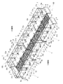
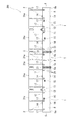
図1〜図4から分かるように、第1実施形態に係る作業用足場は、複数個、ここでは6個の浮体ブロック1を前後方向(長手方向)に3個、左右方向(短手方向)に2個、つまり1列3個で2列並べ、相互に連結してなる作業用足場本体100(図5参照)を備える。
上記浮体ブロック1は、図6に示すように、天板2及び底板3が平行に配された中空箱状、ここでは直方体状に形成されている。
具体的には、浮体ブロック1は、図7に示すように上面が開口し内部前後方向に3個配設された補強枠4で補強された箱体と、この箱体の上面開口を溶接等により密閉閉塞する、同箱体の底板3に平行な天板1とからなる(箱体の上面開口に天板1を溶接した後は、天板1は開閉できない)。上記3個の補強枠4中、中央の補強枠4は、箱体前後方向中央に配設される。残りの2個の補強枠4は、中央の補強枠4の位置を境に線対称となる前後方向適宜位置に配設される。
この浮体ブロック1の前後板5,6は、浮体ブロック1の底板3側及び左右側板7,8側に延出するフランジ部5a,6aを有して形成され、このフランジ部5a,6aには、浮体ブロック連結穴9が穿設されている。浮体ブロック連結穴9はフランジ部5a,6aの左右側及び下側に適宜間隔置いて複数個穿設されている。
フランジ部5a,6aは、浮体ブロック1の天板2側には形成されていない。天板2面上にフランジ部5a,6aが突出すると作業者が躓く虞があるからであるが、この天板2側については、前後板5,6自体に浮体ブロック連結穴9が穿設されている。この天板2側の浮体ブロック連結穴9も複数個、ここでは2個穿設されているが、この箇所の浮体ブロック連結穴9への図示しないボルトの挿通、ナットの緊締は、天板2に設けられたレセス10内で行われる。符号10aはこのレセス10を開閉するカバーを指す。
更に、浮体ブロック1には、左右側板7,8外面の上部前後方向中央(中央の補強枠4の配設位置にほぼ対応する位置)に、吊上げ用穴11を有する吊上げ用部材12が設けられている。
また、天板2及び底板3の前後方向適宜位置(中央の補強枠4を除く、2個の補強枠4の配設位置にほぼ対応する位置)には、各々垂直連結材取付穴13を有する垂直連結材取付部材14が設けられている。浮体ブロック1の左右側板7,8外面の上部側であって、上記中央の補強枠4の配設位置から浮体ブロック1の前後板5,6側に所定距離離れた箇所には、各々水平連結材取付穴15を有する水平連結材取付部材16が2個設けられている。この2個の水平連結材取付部材16の配設位置は、上下方向にずらせてある。
また、浮体ブロック1の左右側板7,8外面の上部側であって、上記吊上げ用部材12、垂直連結材取付部材14及び水平連結材取付部材16の配設位置と重ならない適宜位置には、手すり支持用筒部17が設けられている。
各浮体ブロック1は、アルミニウム合金製であって、その前後部及び左右部の形状が各々対称に形成されている。後述する浮体ブロック1相互の連結に際して、その前後の向きを逆にしても、連結後の向きに相違を生じさせない(向きを反転させるやり直し作業を生じさせない)ためである。
なお、図1、図2、図5〜図7中の、符号18は、後述する伸縮パイプ(パイプサポート)33の下端を支持する伸縮パイプ支持部材を指す。この伸縮パイプ支持部材18は、浮体ブロック1の天板2左右側の前後方向ほぼ中央に設けられている。
As can be seen from FIGS. 1 to 4, the working scaffold according to the first embodiment includes a plurality of, in this case, six, floating
As shown in FIG. 6, the floating
Specifically, as shown in FIG. 7, the floating
The front and
The
Further, the floating
In addition, each of the
In addition, on the upper side of the outer surfaces of the left and
Each floating
In addition, the code |
本第1実施形態では、上記のように構成された浮体ブロック1(図6参照)を6個用意し、それらを以下の部材によって連結して作業用足場本体100(図5参照)が構成される。
すなわち本第1実施形態では、各浮体ブロック1のフランジ部5a,6aに穿設された浮体ブロック連結穴9を用いて浮体ブロック1を前後方向に着脱自在に連結するボルト・ナット(連結具)21を備える。また、浮体ブロック1を左右方向に連結するための垂直連結材22(図5,図8参照)及び水平連結材23(図5,図9参照)を備える。
そして、垂直連結材22を浮体ブロック1に着脱自在に連結するセットピン(連結具)24と、水平連結材23を浮体ブロック1に着脱自在に連結するボルト・ナット(連結具)25とを備える(図5参照)。
なお、垂直連結材22は、上下方向の位置ずれを阻止しつつ左右の両浮体ブロック1を連結する枠状部材であり、左右端の上下には、上記セットピン24を挿通させるセットピン挿通穴26が穿設されている。
また水平連結材23は、水平方向の位置ずれを阻止しつつ左右の両浮体ブロック1を連結する棒状体からなり、2本を上下にX字状に組んで用いられる。各水平連結材23の両端には、連結具25のボルトを挿通させるボルト挿通穴27が穿設されている。2本の水平連結材23はブレースを構成する。
In the first embodiment, six floating body blocks 1 (see FIG. 6) configured as described above are prepared, and these are connected by the following members to form a working scaffold body 100 (see FIG. 5). The
That is, in the first embodiment, bolts and nuts (connectors) for detachably connecting the floating
Then, a set pin (connector) 24 for detachably connecting the vertical connecting
The vertical connecting
The horizontal connecting
そして、上記浮体ブロック連結穴9を用い連結具21によって3個の浮体ブロック1を前後方向に連結し、これを左右各3個、2列について行う。
この2列の浮体ブロックについて、図5,図6に示す浮体ブロック1側に設けられた垂直連結材取付穴13及び水平連結材取付穴15と、図8,図9に示す垂直連結材22及び水平連結材23の各々両端部に設けられたセットピン挿通穴26及びボルト挿通穴27とを用い、図5に示すように連結具24,25によって左右の浮体ブロック1相互を各々着脱自在に連結する。垂直連結材22及び水平連結材23も浮体ブロック1から着脱自在である。
浮体ブロック1のフランジ部5a,6a及び同フランジ部5a,6aに穿設された浮体ブロック連結穴9は、全浮体ブロック1につき、同じ位置にあるので、連結後において、各列につき、前後方向に位置する浮体ブロック1の上下方向及び左右方向の各位置は揃えられる。
同様に、浮体ブロック1に設けられた垂直連結材取付穴13及び水平連結材取付穴15も全浮体ブロック1につき、同じ位置にあるので、連結後において、左右方向に位置する浮体ブロック1の上下方向及び前後方向の各位置は揃えられる。
以上により、図5に示す作業用足場本体100が構成される。
And the three floating body blocks 1 are connected to the front-back direction by the connecting
For these two rows of floating blocks, the vertical connecting
Since the floating
Similarly, since the vertical connecting
Thus, the working scaffold
本第1実施形態では、上記のように構成された作業用足場本体100の上面の外周側に着脱自在に設けられる手すり31(31a〜31c)を備え、また、作業用足場本体100の左右方向に位置する浮体ブロック1相互間の上部開口を塞ぐ渡り廊下32(32a〜32c)を備える(図1〜図4参照)。
手すり31は、その支柱部の下端部分31d(図10参照)を、浮体ブロック1の左右側板7,8外面に設けられた手すり支持用筒部17のうち作業用足場本体100左右側に位置する手すり支持用筒部17に高さ調節自在に挿着され、所定高さで取外し可能に固定される。
渡り廊下32も着脱自在に設けられる。ここでは、浮体ブロック1相互間の上部開口を塞ぐように載置される。渡り廊下32は、水平方向前後左右側、少なくとも水平方向左右側にずれ移動しないように、ストッパ片(図示せず)が下方に突出している。
手すり31及び渡り廊下32は、その配設位置に応じた形状、寸法等を設定した複数種類、ここでは各々3種類(31a〜31c,32a〜32c)用意され、配設位置に応じた種類が選択され、使用される。
本第1実施形態では、渡り廊下32としてはエキスパンドメタルが用いられているが、これのみに限定されない。渡り廊下32上面の高さ位置は、浮体ブロック1の天板面(天板1上面)と同じ高さに揃えられている。また、手すり31及び渡り廊下32は、いずれもアルミニウム合金製であって、必要に応じて塗装が施される。基本的には、手すり31は塗装されている。
以上により、図1に示す第1実施形態に係る作業用足場200が構成される。
なお、作業用足場200は(浮体ブロック1及び作業用足場本体100も)、水面上を浮くことが可能であることはいうまでもない。
The first embodiment includes handrails 31 (31a to 31c) that are detachably provided on the outer peripheral side of the upper surface of the working scaffold
The
The passage corridor 32 is also detachable. Here, it mounts so that the upper opening between floating body blocks 1 may be plugged up. The crossing corridor 32 has a stopper piece (not shown) protruding downward so as not to shift and move to the horizontal front-rear left-right side, at least the horizontal left-right side.
The
In the first embodiment, expanded metal is used as the crossing corridor 32, but is not limited thereto. The height position of the upper surface of the transfer hallway 32 is aligned with the same height as the top plate surface of the floating block 1 (upper surface of the top plate 1). Moreover, the
As described above, the working
Needless to say, the working scaffold 200 (also the floating
この作業用足場200は、設置する桟橋等の水域構造物近くの地上で組み立てられた後、同水域構造物の下方に設置され、同水域構造物下面の点検・補修作業に供される。
以下、上記作業用足場200の設置方法について図12〜図20を参照して説明する。
まず、作業用足場200を地上で組み立てる作業用足場組立工程を実行する(図12〜図15参照)。この地上での作業用足場200の組み立ての詳細は後述する。
The
Hereinafter, the installation method of the said working
First, a work scaffold assembling step for assembling the
作業用足場200の地上での組み立てを終えると、作業用足場吊上げ降ろし工程を実行する。すなわち、図16に示すように、その組み立てられた作業用足場200を、例えばラフタークレーン等のクレーン51によって吊上げ移動して、点検・補修する桟橋等の水域構造物300近くの水面61に降ろし浮かべる。なお図中310は、水域構造物300の支柱である。
作業用足場200の上記吊上げ移動は、浮体ブロック前後板5,6の各フランジ部5a,6aに穿設された浮体ブロック連結穴9中の最上部に位置する浮体ブロック連結穴9を用いて行う。この最上部に位置する浮体ブロック連結穴9は、吊上げ用穴兼用であって、他の浮体ブロック連結穴9よりも径が大きい。
上記吊上げ移動は、例えば、作業用足場200を構成する9個の浮体ブロック1がなす平面視長方形の対角に位置する4個の吊上げ用穴兼用の浮体ブロック連結穴9に、各々シャックル(図示せず)を取り付ける。そして、このシャクルと吊り治具41をロープ42で結び、この吊り治具41に、他端がクレーン51のフック52に係合されたロープ43の一端を結び、クレーン51の操作で引っ張り上げ、移動することにより行う。
When the assembly of the
The lifting movement of the working
The lifting movement is performed by, for example, shackles (see FIG. 4) in the floating
上記シャックルを、前後方向中央に位置する左右2個の浮体ブロック1がなす平面視長方形の対角に位置する4箇所の吊上げ用穴兼用の浮体ブロック連結穴9に取り付けてもよい。この場合、上記4箇所は、各々前後2個の浮体ブロック1の吊上げ用穴兼用の浮体ブロック連結穴9が重なり合っている箇所であり、シャックルは、この箇所のボルト・ナット(連結具)21に代えて各々取り付けられる。
この場合は、各シャックルに、各々他端がクレーン51のフック52に係合されたロープ43の一端を結び、クレーン51の操作で引っ張り上げ、移動することにより作業用足場200を吊上げ移動する。この例では、各シャックルは、浮体ブロック1のフランジ部5a,6aが2枚重ねられた4箇所に取り付けられ、各2枚重ねの箇所で作業用足場200が吊り上げられるので、より堅固な吊上げが可能となる。
The shut cycle, may be attached to the floating body
In this case, moving each shuts cycle, each other end knot one end of the
次に、水面61に浮かべた作業用足場200を、図17に示すように、水域構造物300の下方の所望位置(作業用足場200の設置場所)に水面61上を移動させる作業用足場移動工程を実行する。この作業用足場200の移動は、例えば水面61上のボート(図示せず)や水域構造物300の適宜箇所に係止させたウインチ71等で牽引することにより行われる。
次に、移動させた作業用足場200を、図18に示すように、水域構造物300の下面301から所定間隔置いた高さまで水面61から吊上げ浮上させる作業用足場吊上げ浮上工程を実行する。作業用足場200の上記浮上はウインチ71等を用いて行われる。
最後に、作業用足場揺れ止め固定工程を実行する。すなわち、図19、図20に示すように、伸縮パイプ33の下端を作業用足場200の伸縮パイプ支持部材18に支持させ、同伸縮パイプ33の上端を伸長させて水域構造物300の下面301に圧接させた状態で、つまり作業用足場200及び水域構造物300相互間に伸縮パイプ33を突っ張らせた状態でその長さを固定する。
以上により、作業用足場200の設置を終了する。
なお、作業用足場200の設置場所から地上への撤去、地上での分解は、上述した組立、設置手順の逆の手順で行える。
Next, as shown in FIG. 17, the
Next, as shown in FIG. 18, the working
Finally, the work scaffolding stabilization process is performed. That is, as shown in FIGS. 19 and 20, the lower end of the
Thus, the installation of the
Removal of the
上記作業用足場組立工程における作業用足場200の地上での組み立ては、例えば図12〜図15に示す手順で行われる。
まず、点検・補修する水域構造物300近くの地上における組立エリアの浮体ブロック1の組立位置に盤木40を配置し、浮体ブロック1を、トラッククレーン等のクレーン(図示せず)を使用して吊り上げ、所定の位置に配置する。これを6個の浮体ブロック1について繰り返し、1列3個で2列6個の浮体ブロック1の配置を行う(図12参照)。
各浮体ブロック1は前後部及び左右部の形状が各々対称に形成されているので、浮体ブロック1単体については、上記配置の際の前後の向きに注意を払う必要はない。
浮体ブロック配置の際の浮体ブロック1の吊上げ移動は、例えば浮体ブロック1の左右側板7,8に設けられた吊上げ用部材12の吊上げ用穴11にシャックル(図示せず)を取り付け、このシャックルと上記クレーンのフック間とをロープ(図示せず)で結び、同クレーンを操作して引っ張り上げ、移動することにより行われる。
盤木40を、初めから図12に示すように8個配置せず、後述する前後2個の浮体ブロック1の連結を終えるごとに、次の浮体ブロック1の連結に係る盤木40を配置するようにしてもよい。
また図12では、浮体ブロック1のフランジ部5a,6a部分を盤木40上に置いているが、浮体ブロック1の前後板5,6間の中間部分を盤木40上に置くようにしてもよい。
Assembly of the
First, the
Each of the floating
The lifting movement of the floating
As shown in FIG. 12, eight board blocks 40 are not arranged from the beginning, and each time the connection of two floating body blocks 1 to be described later is finished, the
In FIG. 12, the
次に、前後方向(長手方向)3個、2列の浮体ブロック1を連結する。具体的には、左右各列の前後方向中央の浮体ブロック1と、その前後の浮体ブロック1とを各々連結する。連結は、浮体ブロック1の前後板5,6に形成されたフランジ部5a,6aの浮体ブロック連結穴9に通したボルトにナットを緊締した(連結具21を用いた)ボルト締めにより行う(図13参照)。フランジ部5a,6a及び同フランジ部5a,6aの浮体ブロック連結穴9は、全浮体ブロック1につき同位置にあるので、連結後において、前後方向に位置する両浮体ブロック1の上下方向及び左右方向の各位置は揃えられる。上記ボルトは、異種金属接触による電蝕を防ぐため絶縁ボルトが使用される。
なお、前後方向の浮体ブロック1の連結は、浮体ブロック1の前後板5,6の天板2側に穿設された浮体ブロック連結穴9に通したボルトにナットを緊締した(連結具21を用いた)ボルト締めによっても行われる。このボルト締めは、天板2に設けられたレセス10(図7参照)のカバー10aを開放してそのレセス10内で行われる。ボルト締め後にはレセス10のカバー10aを閉じて、カバー10aを天板面から突出させない。
浮体ブロック1を、初めから図12に示すように1列(3個)あるいは2列(6個)配置せず、前後2個の浮体ブロック1の連結を終えるごとに、次の前後2個の浮体ブロック1の連結を行うように、順次、必要な浮体ブロック1を配置し、連結するようにしてもよい。
Next, three front and rear directions (longitudinal directions) and two rows of floating
In addition, the connection of the floating
As shown in FIG. 12, the floating
次に、左右方向の浮体ブロック1を連結する。
この連結は、6個の垂直連結材22と6本の水平連結材23とで行う(図14参照)。 具体的には、浮体ブロック1の天板2及び底板3に設けられ、浮体ブロック1の組立位置への配置によって対向位置する垂直連結材取付部材14間に垂直連結材22を置く。そして、垂直連結材22左右側の上下に開けられたセットピン挿通穴26(図8参照)を垂直連結材取付部材14に開けられ垂直連結材取付穴13(図6参照)に合わせ、各々上方からセットピン24を挿通(ピン止め)して、左右の浮体ブロック1における上下方向の位置ずれを阻止しつつその左右の浮体ブロック1を連結する。セットピン24の下端側には、同セットピン24の抜け止め(図示せず)が着脱自在に施される。
この連結を、左右の浮体ブロック1一組について2個、合計三組、6個の垂直連結材22について行う。
Next, the floating
This connection is performed by six vertical connecting
This connection is performed for two sets of left and right floating body blocks 1, a total of three sets, and six
上記左右の浮体ブロック1の垂直連結材22による連結を終えた後、あるいは垂直連結材22による連結作業の妨げとならない範囲(手順)で、上記垂直連結材22による連結作業と並行して左右の浮体ブロック1の水平連結材23による連結を行う。
具体的には、右側の浮体ブロック1の左側板7の前端側に配設された水平連結材取付部材16と、左側の浮体ブロック1の右側板8の後端側に配設された水平連結材取付部材16との間に1本の水平連結材23を架け渡し、同水平連結材23両端のボルト挿通穴27(図9参照)を上記水平連結材取付部材16の水平連結材取付穴15(図6参照)に各々合わせて上方からボルトを挿通し、同ボルトにナットを緊締(連結具25によりボルト締め)する。
続いて、左側の浮体ブロック1の右側板8の前端側に配設された水平連結材取付部材16と、右側の浮体ブロック1の左側板7の後端側に配設された水平連結材取付部材16との間にもう1本の水平連結材23を架け渡し、同水平連結材23両端のボルト挿通穴27(図9参照)を上記水平連結材取付部材16の水平連結材取付穴15(図6参照)に各々合わせて上方からボルトを挿通し、同ボルトにナットを緊締(連結具25によりボルト締め)する。
これにより、上下にX字状に組んだ2本の水平連結材(ブレース)23により、左右の浮体ブロック1における水平方向の位置ずれを阻止しつつその左右の浮体ブロック1を連結する。
この連結を、左右の浮体ブロック1一組について2本、合計三組、6本の水平連結材23について行う。
浮体ブロック1に設けられた垂直連結材取付穴13及び水平連結材取付穴15(垂直連結材取付部材14及び水平連結材取付部材16:図6参照)は、全浮体ブロック1につき、同じ位置にあるので、連結後において、左右方向に位置する両浮体ブロック1の上下方向及び前後方向の各位置は揃えられる。
以上により、作業用足場本体100の組み立てを終える(図14参照)。
After the connection of the left and right floating
Specifically, a horizontal connecting
Subsequently, a horizontal connecting
As a result, the left and right floating
This connection is performed for two
The vertical connecting
Thus, the assembly of the working
作業用足場本体100の組み立てを終えると、図15に示すように、その作業用足場本体100の上面の外周側に着脱自在に手すり31(31a〜31c)を設ける。すなわち、各手すり31の支柱部の下端部分31d(図10参照)を浮体ブロック1の左右側板7,8外面に設けられた手すり支持用筒部17に挿着し、所定高さで取外し可能に固定する。
また、作業用足場本体100の左右方向に位置する浮体ブロック1相互間の上部開口を塞ぐように渡り廊下32(32a〜32c)を設ける。ここでは、渡り廊下32は浮体ブロック1相互間の上部開口を塞ぐ位置に単に載置するだけであり、簡単に着脱できる。
以上で作業用足場200の組み立てが終わる(図15、図1参照)。
When the assembly of the working scaffold
Moreover, the crossing corridor 32 (32a-32c) is provided so that the upper opening between the floating body blocks 1 located in the left-right direction of the working scaffold
This completes the assembly of the working scaffold 200 (see FIGS. 15 and 1).
上述第1実施形態に係る作業用足場200では、主要部である浮体ブロック1は天板2及び底板3が平行に配された直方体状に、つまりコンパクトで荷造り荷下ろし等において扱いやすく、また前後部及び左右部の形状が各々対称で、前後の向き等に注意を払うことなく配置、組立可能に形成されている。しかも、浮体ブロック1相互、及び浮体ブロック1と連結材22,23とは着脱自在に連結され、特にボルト締めやピン止めにより連結され、また、手すり31(31a〜31c)や渡り廊下32(32a〜32c)も着脱自在に設けられ、更に浮体ブロック1、手すり31及び渡り廊下32がアルミニウム合金製である。
したがって、この第1実施形態に係る作業用足場200によれば、浮体ブロック1による組立、分解・撤去、移動等の準備、実行等において極めて扱いやすく、その組立、分解・撤去、移動等が極めて簡単、迅速に行える。すなわち、短時間での設置、撤去が可能である。したがって、台風到来等による荒天の直前でも撤去が可能であって、荒天への急変による破損事故が著しく減少する。したがって、点検・補修作業日程の調整が容易となり、作業の進捗を早めて点検・補修作業の全工程の時間を短縮でき、したがってまた、大型連休等、連休時まで待つことなく点検・補修作業が行える等の効果を発揮できる。
また、上述した作業用足場200の設置方法によれば、作業用足場200自体の組立、移動等が上記のように極めて簡単、迅速に行えるので、その作業用足場200の設置が簡単、迅速に行える。すなわち、短時間での設置が可能であって、点検・補修作業日程の調整が容易となり、作業の進捗を早めて点検・補修作業の全工程の時間を短縮でき、したがってまた、大型連休等、連休時まで待つことなく点検・補修作業が行える等の効果を発揮できる。
In the working
Therefore, according to the working
Further, according to the above-described method for installing the
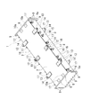
なお、上述第1実施形態では、図1に示すように浮体ブロック1の前後方向の連結個数を3個(1列3個)としたが、これのみに限定されることはない。例えば図21に示す第2実施形態のように、浮体ブロック1の前後方向の連結個数を2個(1列2個)としてもよい。この第2実施形態によっても、上述第1実施形態におけると同様の効果を発揮できる。
In the first embodiment described above, the number of connected floating
また、浮体ブロック1を左右方向にのみ複数個、例えば図22に示す第3実施形態のように左右方向にのみ2個、連結して作業用足場200を構成してもよい。このような第3実施形態においても、左右の浮体ブロック1は、垂直連結材22及び水平連結材23によって着脱自在に連結されており、その組立及び分解は簡単に行うことができる。更に、浮体ブロック1を「コ」の字状に組み合わせ、着脱自在に連結して作業用足場200を構成してもよい。
Further, the
1:浮体ブロック、2:天板、3:底板、5:前板、6:後板、5a,6a:フランジ部、7:左側板、8:右側板、21:ボルト・ナット(連結具)、22:垂直連結材、23:水平連結材(ブレース)、24:セットピン(連結具)、25:ボルト・ナット(連結具)、31(31a〜31c):手すり、32(32a〜32c):渡り廊下(エキスパンドメタル)、33:伸縮パイプ(パイプサポート)、40:盤木、41:吊り治具、51:クレーン、61:水面、71:ウインチ、100:作業用足場本体、200:作業用足場、300:水域構造物。 1: floating block, 2: top plate, 3: bottom plate, 5: front plate, 6: rear plate, 5a, 6a: flange, 7: left side plate, 8: right side plate, 21: bolt and nut (connector) , 22: vertical connecting material, 23: horizontal connecting material (brace), 24: set pin (connecting tool), 25: bolt and nut (connecting tool), 31 (31a-31c): handrail, 32 (32a-32c) : Crossing corridor (expanded metal), 33: Telescopic pipe (pipe support), 40: Wood block, 41: Hanging jig, 51: Crane, 61: Water surface, 71: Winch, 100: Work scaffold body, 200: Work Scaffold, 300: water structure.
Claims (9)
この作業用足場本体の上面の外周側に着脱自在に設けられる手すりと、
前記左右方向に位置する浮体ブロック相互間の上部開口を塞ぐように着脱自在に設けられる渡り廊下と、を具備する作業用足場を水域構造物の下方に設置する作業用足場の設置方法であって、
前記作業用足場を地上で組み立てる作業用足場組立工程と、
組み立てられた作業用足場を吊り上げて水面に降ろし浮かべる作業用足場吊上げ降ろし工程と、
水面に浮かべた作業用足場を前記水域構造物の下方位置に水面上を移動させる作業用足場移動工程と、
移動させた作業用足場を前記水域構造物の下面から所定間隔置いた高さまで前記水面から吊上げ浮上させる作業用足場吊上げ浮上工程と、
吊り上げ浮上された作業用足場に下端を支持させた伸縮パイプの上端を伸長させて前記水域構造物の下面に圧接させた状態でその長さを固定する作業用足場揺れ止め固定工程と、を含むことを特徴とする作業用足場の設置方法。 A plurality of aluminum alloy floating blocks formed in a hollow box shape and symmetrically formed in the front and rear portions and the left and right portions are detachably connected in the front-rear direction, and the floating blocks are detachable in the left-right direction. A working scaffold body connected by a plurality of connecting members;
A handrail detachably provided on the outer peripheral side of the upper surface of the working scaffold main body,
There in the installation method of the work platform to be installed and corridors which is freely disposed detachably so as to close the upper opening between the floating blocks mutually positioned in the lateral direction, the work scaffolding it includes a downwardly waters structure And
A work scaffold assembly process for assembling the work scaffold on the ground;
Lifting and lowering the assembled work scaffold and lowering it to the surface of the water;
A work scaffold moving step of moving the work scaffold floated on the water surface to a position below the water structure, on the water surface;
Lifting and lifting the working scaffold for lifting the lifted work scaffold from the water surface to a height spaced from the lower surface of the water structure by a predetermined distance;
A working platform anti-swaying fixing step of fixing the length of the telescopic pipe that supports the lower end of the suspended working scaffold and extending the upper end of the extension pipe so as to be in pressure contact with the lower surface of the water structure. A method for installing a working scaffold characterized by the above .
浮体ブロックを、前後方向に複数個着脱自在に連結すると共に、該浮体ブロックを、左右方向に着脱自在の連結材を介して複数個連結して作業用足場本体を組み立て、この組み立てられた作業用足場本体の上面の外周側に着脱自在に手すりを設けると共に、左右方向に位置する浮体ブロック相互間の上部開口を塞ぐように着脱自在に渡り廊下を設けることを特徴とする請求項1に記載の作業用足場の設置方法。 In the work scaffold assembly process,
A plurality of floating blocks are detachably connected in the front-rear direction, and a plurality of the floating blocks are connected via a detachable connecting member in the left-right direction to assemble the work scaffold main body. The work according to claim 1, wherein a handrail is detachably provided on the outer peripheral side of the upper surface of the scaffold main body, and a crossover corridor is provided detachably so as to close an upper opening between the floating blocks located in the left-right direction. How to install a scaffold.
この作業用足場本体の上面の外周側に着脱自在に設けられる手すりと、
前記左右方向に位置する浮体ブロック相互間の上部開口を塞ぐように着脱自在に設けられる渡り廊下と、
前記各浮体ブロックに設けられた吊上げ用穴とを具備し、
前記浮体ブロックは、底板側及び左右側板側に延出するフランジ部が形成された前後板と、天板の前記前後板に臨む前後方向端部に設けられた開閉可能なカバーを有するレセスと、を有し、前記前後板のフランジ部と前記レセスと対応する位置とには浮体ブロック連結穴が形成されており、
前記浮体ブロック相互の前記浮体ブロック連結穴を介してボルト止めされて、浮体ブロック列が構成されていることを特徴とする作業用足場。 A plurality of aluminum alloy floating blocks formed in a hollow box shape and symmetrically formed in the front and rear portions and the left and right portions are detachably connected in the front-rear direction, and the floating blocks are detachable in the left-right direction. A working scaffold body connected by a plurality of connecting members;
A handrail detachably provided on the outer peripheral side of the upper surface of the working scaffold main body,
A passageway provided detachably so as to close the upper opening between the floating blocks located in the left-right direction,
A lifting hole provided in each of the floating blocks,
The floating block includes a front and rear plate formed with flange portions extending to the bottom plate side and the left and right side plate side, and a recess having a cover that can be opened and closed provided at a front and rear end portion facing the front and rear plates of the top plate, A floating block connecting hole is formed at a position corresponding to the flange portion of the front and rear plates and the recess,
The floating block each other of said bolted through the floating block coupling holes, working scaffolding, characterized in that the floating body block row is formed.
Priority Applications (1)
| Application Number | Priority Date | Filing Date | Title |
|---|---|---|---|
| JP2014115796A JP6401937B2 (en) | 2014-06-04 | 2014-06-04 | Working scaffold and installation method |
Applications Claiming Priority (1)
| Application Number | Priority Date | Filing Date | Title |
|---|---|---|---|
| JP2014115796A JP6401937B2 (en) | 2014-06-04 | 2014-06-04 | Working scaffold and installation method |
Publications (2)
| Publication Number | Publication Date |
|---|---|
| JP2015229850A JP2015229850A (en) | 2015-12-21 |
| JP6401937B2 true JP6401937B2 (en) | 2018-10-10 |
Family
ID=54886794
Family Applications (1)
| Application Number | Title | Priority Date | Filing Date |
|---|---|---|---|
| JP2014115796A Active JP6401937B2 (en) | 2014-06-04 | 2014-06-04 | Working scaffold and installation method |
Country Status (1)
| Country | Link |
|---|---|
| JP (1) | JP6401937B2 (en) |
Families Citing this family (4)
| Publication number | Priority date | Publication date | Assignee | Title |
|---|---|---|---|---|
| JP6018691B1 (en) * | 2015-12-11 | 2016-11-02 | 株式会社フジみらい | Suspension scaffold construction method and suspension scaffold with float in bridge structure |
| JP6396543B1 (en) * | 2017-07-07 | 2018-09-26 | 株式会社流機エンジニアリング | Scaffold anchors |
| JP7463034B2 (en) | 2020-06-30 | 2024-04-08 | 中国電力株式会社 | Suspended scaffolding equipment and suspended scaffolding operation method |
| CN112942871B (en) * | 2021-02-02 | 2022-11-22 | 广州亿新建设集团有限公司 | Dustproof heat sink is used in high-rise building construction |
Family Cites Families (8)
| Publication number | Priority date | Publication date | Assignee | Title |
|---|---|---|---|---|
| JPS5120199Y2 (en) * | 1973-07-17 | 1976-05-27 | ||
| US4085696A (en) * | 1976-11-01 | 1978-04-25 | Shorter Jr Myron L | Utility chase for floating units |
| JPS5855112Y2 (en) * | 1979-09-13 | 1983-12-16 | 東亜建設工業株式会社 | Floating body coupling device |
| JPH0744541U (en) * | 1991-11-14 | 1995-11-21 | テクノ創建株式会社 | Work floor collective suspension construction payment method |
| JP2001323415A (en) * | 2000-05-19 | 2001-11-22 | Nippon Scuba Sensui Kk | Scaffold structure for working for water's edge structure and moving operation mechanism therefor |
| JP3612267B2 (en) * | 2000-07-26 | 2005-01-19 | 倉本鐵工株式会社 | Split assembly work trolley |
| JP4922576B2 (en) * | 2005-06-22 | 2012-04-25 | ジーオーピー株式会社 | Floating structure |
| JP4115472B2 (en) * | 2005-08-11 | 2008-07-09 | 株式会社ブリッジ・エンジニアリング | Assembly method for scaffolds in bridge structures |
-
2014
- 2014-06-04 JP JP2014115796A patent/JP6401937B2/en active Active
Also Published As
| Publication number | Publication date |
|---|---|
| JP2015229850A (en) | 2015-12-21 |
Similar Documents
| Publication | Publication Date | Title |
|---|---|---|
| JP4625532B1 (en) | Construction method of temporary closing structure around bridge pier and platform used for construction | |
| JP6401937B2 (en) | Working scaffold and installation method | |
| CN102953342B (en) | Assembling and lifting method of half-span skeleton of tied arch bridge | |
| JP5522812B1 (en) | Bucket fittings | |
| KR101722595B1 (en) | Divided Erection Method Of Flare Tower | |
| CN101725114B (en) | Method for hoisting hawser of long-span cable-stayed bridge and equipment thereof | |
| CN103171976A (en) | Hoisting method for shipyard gantry crane | |
| JP5035505B2 (en) | Temporary scaffolding for pile-type offshore structures | |
| JP5637480B2 (en) | Dismantling method of support for slab construction in pile pier construction | |
| KR101590789B1 (en) | Connection structure for block turnover jig and mothod for fixing the block thereof | |
| CN102328739A (en) | Erection-free combined scaffold device for ship | |
| JP5087154B2 (en) | Construction method and scaffold structure of water structure | |
| RU2707615C1 (en) | Frame system and method of its operation | |
| CN110077963B (en) | Installation method of large tank | |
| JP4700980B2 (en) | How to replace the Gangway Tower | |
| CN202969246U (en) | Semi-stride hoisting bowstring arch bridge | |
| KR101358216B1 (en) | Pin-type lifting frame and derrick installation method using the pin-type lifting frame | |
| JP5301410B2 (en) | Repair method for pier structure | |
| JP2006264668A (en) | Ladder | |
| KR101607942B1 (en) | Method for loading riser guide tubes | |
| CN112573344A (en) | Hoisting and turning-over device for super-large concrete prefabricated stand plate and using method thereof | |
| KR20110112284A (en) | Device for transporting and placing a bridge of an offshore oil rig for sea operation onto a floating or stationary structure | |
| JP7463034B2 (en) | Suspended scaffolding equipment and suspended scaffolding operation method | |
| CN210162437U (en) | Special-shaped steel pipe arch section bearing device | |
| KR200457268Y1 (en) | device of fixing tower crane for bridge |
Legal Events
| Date | Code | Title | Description |
|---|---|---|---|
| A621 | Written request for application examination |
Free format text: JAPANESE INTERMEDIATE CODE: A621 Effective date: 20170502 |
|
| A977 | Report on retrieval |
Free format text: JAPANESE INTERMEDIATE CODE: A971007 Effective date: 20180209 |
|
| A131 | Notification of reasons for refusal |
Free format text: JAPANESE INTERMEDIATE CODE: A131 Effective date: 20180221 |
|
| A521 | Written amendment |
Free format text: JAPANESE INTERMEDIATE CODE: A523 Effective date: 20180418 |
|
| TRDD | Decision of grant or rejection written | ||
| A01 | Written decision to grant a patent or to grant a registration (utility model) |
Free format text: JAPANESE INTERMEDIATE CODE: A01 Effective date: 20180822 |
|
| A61 | First payment of annual fees (during grant procedure) |
Free format text: JAPANESE INTERMEDIATE CODE: A61 Effective date: 20180910 |
|
| R150 | Certificate of patent or registration of utility model |
Ref document number: 6401937 Country of ref document: JP Free format text: JAPANESE INTERMEDIATE CODE: R150 |
|
| R250 | Receipt of annual fees |
Free format text: JAPANESE INTERMEDIATE CODE: R250 |