JP6401002B2 - Work machine monitoring system - Google Patents
Work machine monitoring system Download PDFInfo
- Publication number
- JP6401002B2 JP6401002B2 JP2014202398A JP2014202398A JP6401002B2 JP 6401002 B2 JP6401002 B2 JP 6401002B2 JP 2014202398 A JP2014202398 A JP 2014202398A JP 2014202398 A JP2014202398 A JP 2014202398A JP 6401002 B2 JP6401002 B2 JP 6401002B2
- Authority
- JP
- Japan
- Prior art keywords
- communication device
- work machine
- status information
- beacon
- ssid
- Prior art date
- Legal status (The legal status is an assumption and is not a legal conclusion. Google has not performed a legal analysis and makes no representation as to the accuracy of the status listed.)
- Active
Links
Images


Description
本発明は、作業機の監視システムに関する。 The present invention relates to a work machine monitoring system.
従来より、車両の保管場所を監視する技術として特許文献1に示すものがある。
特許文献1では、車両の保管場所である車庫の出入り口に、車両を検知することができるラインセンサを設置する。そのうえで、保管場所の警戒中には、ラインセンサで保管場所に向けて侵入しようとする侵入者を検知できるようにすることにより、保管場所の監視を行っている。
Conventionally, there is a technique shown in Patent Document 1 as a technique for monitoring a storage location of a vehicle.
In patent document 1, the line sensor which can detect a vehicle is installed in the doorway of the garage which is a storage place of a vehicle. In addition, during the alert of the storage location, the storage location is monitored by enabling the line sensor to detect an intruder who attempts to enter the storage location.
特許文献1において、保管場所の監視を開始するには、保管場所に車両を止めた後、保管場所に設置した操作盤等を操作する必要があった。この場合、操作盤の操作を忘れてしまうと、保管場所の監視、即ち、車両の監視が行えないという問題がある。また、特許文献1は、自動車等の保管場所の監視を対象としており、作業機等の監視するシステムは未だ開発されていないのが実情である。 In Patent Document 1, in order to start monitoring the storage location, it is necessary to operate an operation panel or the like installed at the storage location after the vehicle is stopped at the storage location. In this case, if the operation panel is forgotten, there is a problem that the storage location cannot be monitored, that is, the vehicle cannot be monitored. Further, Patent Document 1 is intended for monitoring storage locations such as automobiles, and the actual situation is that a system for monitoring work machines or the like has not been developed yet.
本発明は、上記したような従来技術の問題点を解決すべくなされたものであって、作業機の監視を簡単に行うことを目的とする。 The present invention has been made to solve the above-described problems of the prior art, and an object thereof is to easily monitor a working machine.
上述の目的を達成するため、本発明においては以下の技術的手段を講じた。
作業機の監視システムは、作業機に設けられた通信装置であって、前記作業機の状態を示すステータス情報を含むビーコンをブロードキャスト信号として出力する出力部を有する第1通信装置と、前記作業機を保管する保管場所又は当該保管場所の周囲に設置され、且つ、前記第1通信装置から送信された前記ブロードキャスト信号であるビーコンを無線通信で受信する第2通信装置と、を備え、前記第2通信装置は、監視開始後、前記ブロードキャスト信号として受信したビーコンのステータス情報の変化があった場合に外部に警報を出力可能な監視部を有している。
In order to achieve the above-described object, the present invention takes the following technical means.
The work machine monitoring system is a communication device provided in the work machine, the first communication device having an output unit that outputs a beacon including status information indicating a state of the work machine as a broadcast signal, and the work machine And a second communication device that is installed around the storage location and that receives the beacon that is the broadcast signal transmitted from the first communication device by wireless communication. The communication device has a monitoring unit capable of outputting an alarm to the outside when there is a change in the status information of the beacon received as the broadcast signal after the start of monitoring.
前記出力部は、前記第1通信装置を識別可能な識別子と前記ステータス情報とを含むビーコンを前記第2通信装置に出力する。
前記第1通信装置は、前記作業機のイグニッションスイッチがオンされたこと及び前記イグニッションスイッチがオフされたことのいずれかを前記ステータス情報として前記ビーコンで出力し、前記監視部は、前記イグニッションスイッチがオフされたことを示すステータス情報を前記ブロードキャスト信号で受信している状態から、前記イグニッションスイッチがオンされたことを示すステータス情報を前記ブロードキャスト信号を受信した場合に、外部に警報を出力する。
The output unit outputs a beacon including an identifier capable of identifying the first communication device and the status information to the second communication device .
The first communication apparatus, one of the and the ignition switch that the ignition switch of the working machine is turned on is turned off to output the beacon as the status information, the monitoring unit, the ignition switch When status information indicating that the ignition switch is turned on is received from the state in which status information indicating that the ignition switch is turned off is received by the broadcast signal, an alarm is output to the outside.
前記第1通信装置は、前記作業機が駆動していない場合のステータス情報と、前記作業機が駆動した場合のステータス情報とが区別可能となるように、駆動の有無によってビーコンを変更する信号変更部を有し、前記監視部は、前記信号変更部で変更されたビーコンに基づいて外部に警報を出力する。
前記監視部は、前記ビーコンを受信している状態から前記ビーコンが受信できなくなった場合に、外部に警報を出力する。
The first communication apparatus, and status information when the working machine is not driven, so that the status information when the working machine is driven is distinguishable, signal change for changing the beacon by the presence or absence of the driving The monitoring unit outputs an alarm to the outside based on the beacon changed by the signal changing unit.
The monitoring unit outputs an alarm to the outside when the beacon cannot be received from the state in which the beacon is received.
本発明によれば、作業機の監視を簡単に行うことができる。 According to the present invention, it is possible to easily monitor a work machine.
以下、本発明に係る作業機の監視システムについて、適宜図面を参照しながら説明する。
図1は、作業機の監視システムの概略図である。
作業機の監視システム1は、建設機械(例えば、バックホー)、農業機械(例えば、トラクタ、コンバイン、田植機)等の作業機の監視を行うシステムである。図1に示すように、監視システム1は、第1通信装置2と、第2通信装置3とを有している。
Hereinafter, a monitoring system for a work machine according to the present invention will be described with reference to the drawings as appropriate.
FIG. 1 is a schematic diagram of a work machine monitoring system.
The work machine monitoring system 1 is a system that monitors work machines such as construction machines (for example, backhoes) and agricultural machines (for example, tractors, combine harvesters, rice transplanters). As shown in FIG. 1, the monitoring system 1 includes a
第1通信装置2は、作業機4に搭載されていて、第2通信装置3と無線通信可能な装置である。第2通信装置3は、携帯可能な携帯端末であって、例えば、比較的演算能力の高いスマートフォン(多機能携帯電話)やタブレットPC等で構成されている。
第2通信装置3は、持ち運びが可能であるが、作業機4を保管する保管場所Pに設置された収容箱5に収容されている。或いは、第2通信装置3は、保管場所Pの周囲に設置された収容箱5に収容されている。保管場所Pとは、作業機4が農業機械の場合は、例えば、農家の納屋であり、作業機4が建設機械の場合は、倉庫である。当然の如く、保管場所Pは、前述した例に限定されず、作業機4を保管するために予め決められた場所であればよい。
The
The
以下、第1通信装置2及び第2通信装置3について詳しく説明する。
図2に示すように、第1通信装置2は、作業機4に設けられた車載通信ネットワークに接続されている。第1通信装置2は、取得部11と、信号変更部12と、第1通信部(出力部)13と、第1記憶部14とを有している。取得部11及び信号変更部12は、電子回路やCPUに格納されたプログラム等から構成されている。
Hereinafter, the
As shown in FIG. 2, the
取得部11は、車載通信ネットワークに流れる作業機4の情報(ステータス情報ということがある)を取得する。取得部11は、例えば、ステータス情報として、作業機4に搭載されたセンサ(アクセルペダルセンサ、エンジン回転検出センサ、クランク位置センサ、燃料センサ、水温センサ、振動センサ等)の値を取得する。また、取得部11は、ステータス情報として、作業機4に搭載されたスイッチ(イグニッションスイッチ、駐車ブレーキスイッチ、PTOスイッチ等)の状態(ON、OFF)、或いは、作業機4に搭載されたCPU等の制御部の制御信号を取得可能である。つまり、取得部11は、作業機4の状態を示すステータス情報を取得するものである。
The
信号変更部12(情報付加部)は、取得部11によって取得した作業機4の状態(ステータス情報)を、ビーコンに付加する。ここで、ビーコンとは、第2通信装置3と第1通信装置2との無線通信で用いられるブロードキャストの信号であって、サービスセット識別子(SSID)などを含む信号である。
信号変更部12は、SSIDにステータス情報を付加する。以下、説明の便宜上、予め定められたSSIDのことを「設定SSID」、ステータス情報が付加されたSSIDのことを「変更SSID」ということがある。
The signal changing unit 12 (information adding unit) adds the state (status information) of the
The
図2は、SSIDの推移を示した図である。
図2に示すように、時点P1において、作業機4のイグニッションスイッチ(IG−SW)がオフ(OFF)からオン(ON)に変化した場合、取得部11は、イグニッションスイッチがオンしたことを示すステータス情報であるキーオン情報を取得する。取得部11がキーオン情報を取得すると、信号変更部12は、設定SSIDである「KUBOTA」に、キーオン情報を付加することにより、変更SSIDを「KUBOTA−010」に変更する。即ち、信号変更部12は、イグニッションスイッチがオンしたことを示す「010」を、設定SSIDの末尾に加える。なお、設定SSIDである「KUBOTA」と、「010」との間に示される記号「−」は、設定SSIDと、新たに加えられたキーオン情報との区切りを示している。
FIG. 2 is a diagram showing the transition of the SSID.
As illustrated in FIG. 2, when the ignition switch (IG-SW) of the
また、時点P2において、イグニッションスイッチ(IG−SW)がオン(ON)からオフ(OFF)に変化した場合、取得部11は、イグニッションスイッチがオフになったことを示すステータス情報であるキーオフ情報を取得する。取得部11がキーオフ情報を取得すると、信号変更部12は、変更SSID(KUBOTA−010)を設定SSID(KUBOTA)に戻す処理を行う。したがって、信号変更部12では、イグニッションスイッチのオン、オフを示すステータス情報に基づいてSSIDを変更する。上述した実施形態では、イグニッションスイッチのオン又はオフにおけるステータス情報について説明したが、当然の如く、これに限定されない。
Further, when the ignition switch (IG-SW) changes from on (ON) to off (OFF) at the time point P2, the
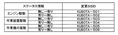
本発明においては、信号変更部12は、作業機4の動き(駆動)を確認できるステータス情報に基づいてSSIDを変更することが好ましい。図3に示すように、例えば、エンジンの駆動の有無、作業装置の駆動の有無、作業機4の振動の有無、走行の有無等を示すステータス情報に基づいて、SSIDを変更する。なお、エンジンの駆動の有無は、上述したようにイグニッションスイッチ、エンジン回転検出センサ、クランク位置センサによって検出することができる。作業機4の駆動の有無は、作業装置のPTOスイッチのオン又はオフで検出することができる。作業機4の振動の有無は、振動センサで検出することができる。
In this invention, it is preferable that the signal change
したがって、信号変更部12によれば、作業機4の駆動の変化を認識することができるステータス情報を、設定SSIDに付加することができる。
なお、信号変更部12は、変更SSIDを作成するに際して、設定SSIDの末尾にステータス情報を示す文字等(例えば、010、011)を加えていたが、ステータス情報を示す文字等は、設定SSIDのどこの位置に加えてもよい。また、信号変更部12は、所定のステータス情報に基づき、設定SSIDを予め定められた計算式等で変化させてもよい。また、取得部11が取得したステータス情報と、ステータス情報を示す文字との関係は、予め第1通信装置2に記憶されており、信号変更部12は、この関係を用いて変更SSIDを作成する。
Therefore, according to the
In addition, when the
第1通信部13は、通信規格であるIEEE802.11シリーズに準拠したWi−Fi(登録商標)による無線通信を実行する。第1通信部13は、第2通信装置3から受信したデータ(情報)を受信したり、SSID(設定SSID、変更SSID)を含むビーコンを第2通信装置3に出力する。第1通信部13は、例えば、信号変更部12によって設定SSIDが変更された場合には、変更後の変更SSIDを含むビーコンを外部に送信し、信号変更部12による設定SSIDの変更が無い場合には、設定SSIDを含むビーコンを外部に送信する。
The
第1記憶部14は、不揮発性のメモリ等から構成されている。第1記憶部14は、通信に関する通信情報、ステータス情報、変更SSIDを作成するためのデータ等を記憶可能である。通信情報とは、例えば、ネットワーク上において設定された固有のMACアドレス、第1通信装置2を識別するための識別子(設定SSID、変更SSID)、暗号化キー(ネットワークキー)等である。
The 1st memory |
第2通信装置3は、第2通信部17と、第2記憶部18と、監視部19を有している。
第2通信部17は、通信規格であるIEEE802.11シリーズに準拠したWi−Fi(登録商標)による無線通信を実行可能である。また、第2通信部17は、データ通信網や携帯電話通信網によって通信を行うことができる装置であってもよい。
第2記憶部18は、不揮発性のメモリ等から構成されている。第2記憶部18は、通信情報、第1通信装置2から取得したステータス情報を記憶可能である。通信情報は、例えば、ネットワーク上において設定された固有のMACアドレス、暗号化キー(ネットワークキー)、通報先情報(通報先の電子メール)である。
The
The
The
監視部19は、電子回路やプログラム等から構成され、作業機4を監視するものである。具体的には、監視部19は、監視中(監視開始後)において、作業機4の状態が変化すると、外部に警報を出力する。例えば、監視部19は、作業機4のエンジンが停止した状態から始動したり、作業機4が停止している状態から移動を検知すると、外部に警報を出力する。ここで、「作業機4のエンジンが停止した状態から始動した」こと、「作業機4が停止している状態から移動した」ことなどは、上述したように、第1通信装置2から所定間隔毎に外部に出力されるブロードキャスト信号、即ち、SSIDを含むビーコンによって、把握することができる。
The
監視部19の開始は、例えば、第2通信装置3の表示部に表示された監視ボタンを選択することにより行う。なお、監視ボタンを選択後、数十秒後に監視を開始することが好ましい。
図1に示すように、作業等が終了すると、作業者は、作業機4を保管場所Pに移動させ、作業機4を保管場所Pに停止する。保管場所Pでは、通常、作業機4の駆動は停止している。即ち、保管場所Pに作業機4を保管している状況では、エンジン及び作業装置の駆動は無く、作業機4の振動も無い状態である。
The
As shown in FIG. 1, when the work or the like is finished, the worker moves the
保管場所P及び保管場所Pの周囲であって、第1通信装置2から見て第2通信装置3と通信が通信可能な場所には、第2通信装置3を収容する収容箱5が設置されている。上述したように、作業機4を保管場所Pに収容した後、作業者は、第2通信装置3の表示部に表示された監視ボタンを選択し、当該第2通信装置3を収容箱5に収容する。なお、収容箱5内には、電力を供給するコンセント等が納められていて、第2通信装置3は、コンセントに接続されて充電が可能である。また、収容箱5には、施錠装置が設けられていることが望ましい。
A storage box 5 for storing the
このように、作業機1を保管場所に保管している状況下において、図4に示すように、第1通信装置2は、所定の間隔でSSID(設定SSID、変更SSID)を含むビーコンを外部(第2通信装置3)に送信する(S1)。なお、第1通信装置2は、監視の開始、終了に関わらず、ブロードキャスト信号であるビーコンを常に外部に送信している状態である。
In this way, under the situation where the work machine 1 is stored in the storage location, as shown in FIG. 4, the
一方、収容箱5に収容された第2通信装置3は、少なくとも保管場所Pに第1通信装置2が存在する場合には、ビーコンを受信可能である。そのため、第2通信装置3は、第1通信装置2から送信されたSSIDが受信する(S2)。例えば、保管場所Pでは作業機4の駆動が停止しているため、第2通信装置3は、設定SSIDである「KUBOTA」を受信する。
On the other hand, the
このような監視中の状況下で、作業機4のイグニッションスイッチがオンした場合、第1通信装置2は、「イグニッションスイッチがオンになっている」ことを示すステータス情報を含む変更SSIDである「KUBOTA−010」を送信する(S3)。第2通信装置3が「KUBOTA−010」であるSSIDを受信すると(S4)、監視部19は、監視中に、イグニッションスイッチがオフからオンになったこと、即ち、作業機4の状態が変化したことを検知(S5)する。そして、監視部19は、予め定められた通報先に警報を送信する(S6)。例えば、監視部19は、通報先に電子メール等で警報を送信する。なお、警報の伝達は、どのような方式であってもよく、音で警報を知らせても、光で警報を知らせてもよい。
When the ignition switch of the
以上、本発明によれば、作業機1のステータス情報を含むビーコンを第2通信装置3で受信するだけで、作業機1の監視を行うことができる。例えば、作業機1を保管場所に格納して作業機1の駆動を停止し、且つ、第2通信装置3を保管場所或いは保管場所の周囲に設置するだけで、作業機1の見守りを行うことができる。
上述した実施形態では、監視部19は、ビーコンに含まれるステータス情報に基づいて、警報を外部に出力していた。これに代え、監視中において、第2通信装置3がビーコンを受信している状況からビーコンを受信できなくなった場合、即ち、第2通信装置3がSSIDを受信している状況からSSIDを受信できなくなった場合に、監視部19が警報を外部に出力してもよい。
As described above, according to the present invention, the work implement 1 can be monitored only by receiving the beacon including the status information of the work implement 1 with the
In the embodiment described above, the
例えば、図5に示すように、監視中において、作業機4が保管場所Pから移動することにより、第1通信装置2が保管場所Pから外れた場合、第2通信装置3は、第1通信装置2から送信されたSSIDが受信できなくなる。監視部19は、SSIDが受信できなくなったことを受けて、外部に警報を送信する。このようにすれば、作業機4を駆動させずに、即ち、エンジン始動等をせずに盗難を試みた場合であっても、作業機4が保管場所Pから離れたことを検出することができるため、作業機4の盗難防止を行うことができる。今回開示された実施の形態はすべての点で例示であって制限的なものではないと考えられるべきである。本発明の範囲は上記した説明ではなくて特許請求の範囲によって示され、特許請求の範囲と均等の意味及び範囲内での全ての変更が含まれることが意図される。
For example, as illustrated in FIG. 5, when the
上述した実施形態では、作業機1の状態が予め定められた状態になった場合(例えば、イグニッションスイッチがオンになる)にSSIDを変更していたが、作業機1の状態が変化した場合に、SSIDを変更してもよい。例えば、図6に示すように、エンジンの駆動に関して、エンジンが駆動停止している状態から駆動開始に変化した場合(ステータス情報がエンジン駆動の無しから駆動有りに変化した場合)に、変更SSIDに示すようにSSIDを変更してもよい。同様に、作業装置に関して、作業装置が駆動停止している状態から駆動開始に変化した場合に、変更SSIDに示すようにSSIDを変更してもよい。また、作業機の振動に関して、作業機の振動が無い状態から振動が有りに変化した場合に、変更SSIDに示すようにSSIDを変更してもよい。 In the above-described embodiment, the SSID is changed when the state of the work machine 1 becomes a predetermined state (for example, the ignition switch is turned on), but when the state of the work machine 1 changes. The SSID may be changed. For example, as shown in FIG. 6, when the engine is driven, when the engine is stopped from driving to start driving (when the status information is changed from no engine driving to driving), the changed SSID is set. The SSID may be changed as shown. Similarly, regarding the working device, when the working device is changed from the state where the driving is stopped to the start of driving, the SSID may be changed as shown in the changed SSID. Moreover, regarding the vibration of the work machine, when the vibration of the work machine changes from the state without vibration to the presence of vibration, the SSID may be changed as shown in the changed SSID.
上述した実施形態では、第2通信装置3は、持ち運びができる携帯端末であったが、納屋や倉庫等の保管場所に固定した通信装置、即ち、持ち運びができない通信装置であってもよい。
In the embodiment described above, the
1 作業機の監視システム
2 第1通信装置
3 第2通信装置
4 作業機
11 取得部
12 信号変更部
13 第1通信部
14 第1記憶部
17 第2通信部
18 第2記憶部
19 監視部
DESCRIPTION OF SYMBOLS 1 Monitoring system of
Claims (5)
前記作業機を保管する保管場所又は当該保管場所の周囲に設置され、且つ、前記第1通信装置から送信された前記ブロードキャスト信号であるビーコンを無線通信で受信する第2通信装置と、
を備え、
前記第2通信装置は、監視開始後、前記ブロードキャスト信号として受信したビーコンのステータス情報に変化があった場合に外部に警報を出力可能な監視部を有している作業機の監視システム。 A communication device provided in the work machine, the first communication device having an output unit that outputs a beacon including status information indicating a state of the work machine as a broadcast signal ;
A second communication device that is installed in or around the storage location for storing the work implement, and that receives a beacon that is the broadcast signal transmitted from the first communication device by wireless communication;
With
The monitoring system of a work machine, wherein the second communication device has a monitoring unit capable of outputting an alarm to the outside when there is a change in status information of the beacon received as the broadcast signal after the start of monitoring.
前記監視部は、前記イグニッションスイッチがオフされたことを示すステータス情報を前記ブロードキャスト信号で受信している状態から、前記イグニッションスイッチがオンされたことを示すステータス情報を前記ブロードキャスト信号で受信した場合に、外部に警報を出力する請求項1又は2に記載の作業機の監視システム。 The first communication device outputs, as the status information , the beacon that the ignition switch of the work machine is turned on or the ignition switch is turned off ,
When the monitoring unit receives status information indicating that the ignition switch is turned on from the state where the status information indicating that the ignition switch is turned off is received using the broadcast signal, The work machine monitoring system according to claim 1 , wherein an alarm is output to the outside.
前記監視部は、前記信号変更部で変更されたビーコンに基づいて外部に警報を出力する請求項1〜3のいずれかに記載の作業機の監視システム。 The first communication device changes a signal that changes a beacon depending on whether or not it is driven so that status information when the work machine is not driven can be distinguished from status information when the work machine is driven. Part
The work monitoring system according to claim 1, wherein the monitoring unit outputs an alarm to the outside based on the beacon changed by the signal changing unit.
Priority Applications (1)
| Application Number | Priority Date | Filing Date | Title |
|---|---|---|---|
| JP2014202398A JP6401002B2 (en) | 2014-09-30 | 2014-09-30 | Work machine monitoring system |
Applications Claiming Priority (1)
| Application Number | Priority Date | Filing Date | Title |
|---|---|---|---|
| JP2014202398A JP6401002B2 (en) | 2014-09-30 | 2014-09-30 | Work machine monitoring system |
Publications (2)
| Publication Number | Publication Date |
|---|---|
| JP2016071756A JP2016071756A (en) | 2016-05-09 |
| JP6401002B2 true JP6401002B2 (en) | 2018-10-03 |
Family
ID=55864828
Family Applications (1)
| Application Number | Title | Priority Date | Filing Date |
|---|---|---|---|
| JP2014202398A Active JP6401002B2 (en) | 2014-09-30 | 2014-09-30 | Work machine monitoring system |
Country Status (1)
| Country | Link |
|---|---|
| JP (1) | JP6401002B2 (en) |
Cited By (1)
| Publication number | Priority date | Publication date | Assignee | Title |
|---|---|---|---|---|
| WO2023276392A1 (en) | 2021-06-29 | 2023-01-05 | 株式会社クボタ | Monitoring system for work machine |
Family Cites Families (5)
| Publication number | Priority date | Publication date | Assignee | Title |
|---|---|---|---|---|
| JP3823832B2 (en) * | 2002-01-15 | 2006-09-20 | 日立建機株式会社 | Construction machine management system and management method |
| GB0223955D0 (en) * | 2002-10-15 | 2002-11-20 | Koninkl Philips Electronics Nv | Wireless security beacon for consumer equipment |
| JP2004288088A (en) * | 2003-03-25 | 2004-10-14 | Mitsumi Electric Co Ltd | Monitoring arrangement |
| JP2012203526A (en) * | 2011-03-24 | 2012-10-22 | Honda Access Corp | Crime prevention device for vehicles |
| JP2014170316A (en) * | 2013-03-01 | 2014-09-18 | Auto Network Gijutsu Kenkyusho:Kk | Monitoring system |
-
2014
- 2014-09-30 JP JP2014202398A patent/JP6401002B2/en active Active
Cited By (1)
| Publication number | Priority date | Publication date | Assignee | Title |
|---|---|---|---|---|
| WO2023276392A1 (en) | 2021-06-29 | 2023-01-05 | 株式会社クボタ | Monitoring system for work machine |
Also Published As
| Publication number | Publication date |
|---|---|
| JP2016071756A (en) | 2016-05-09 |
Similar Documents
| Publication | Publication Date | Title |
|---|---|---|
| AU2021221470B2 (en) | A tracking and theft-recovery system for mobile assets | |
| EP3466189B1 (en) | System and method for establishing a wireless connection between power tool and mobile device | |
| KR101668288B1 (en) | Battery monitoring system for vehicle using internet of thing and method of thereof | |
| KR101911336B1 (en) | Real-time vehicle operation monitoring method based on mobile terminal | |
| JP5852414B2 (en) | Wireless communication system | |
| US20170032593A1 (en) | Remote wireless keyfob diagnostics | |
| US10705822B2 (en) | Terminal device and software rewriting program | |
| JP7276908B2 (en) | Vehicle diagnostic system, adapter used therein, diagnostic terminal device, portable terminal device, and vehicle diagnostic method | |
| US20150264545A1 (en) | 911 assist by wireless charger with nfc in the vehicle | |
| GB2502590A (en) | In-vehicle apparatus for notifying a user of a mobile device that has been left behind | |
| JP6655318B2 (en) | Vehicle security system | |
| JP5255379B2 (en) | Anti-theft device | |
| CN105270322A (en) | Safety state identifying and alarming method and system for intelligent terminal and intelligent terminal | |
| JP2009161093A (en) | Vehicle security remote monitoring system | |
| KR101034426B1 (en) | The mobile phone cooperating system where the complex function is had | |
| JP2011090457A (en) | Vehicle diagnostic device | |
| JP6401002B2 (en) | Work machine monitoring system | |
| JP6470669B2 (en) | Work machine monitoring system | |
| EP2645347A1 (en) | Apparatus and method for supporting theft protection | |
| JP2007083763A (en) | Working machine side dynamics data management device of remote control system | |
| JP6220176B2 (en) | In-vehicle communication terminal | |
| JP2015058846A (en) | Diagnostic system | |
| JP2009235815A (en) | Position management system of working machine and updating method for work area data | |
| JP6323324B2 (en) | Vehicle communication device and reset guard function control program | |
| JP6428496B2 (en) | Information processing apparatus and information storage apparatus |
Legal Events
| Date | Code | Title | Description |
|---|---|---|---|
| A621 | Written request for application examination |
Free format text: JAPANESE INTERMEDIATE CODE: A621 Effective date: 20161223 |
|
| A977 | Report on retrieval |
Free format text: JAPANESE INTERMEDIATE CODE: A971007 Effective date: 20171129 |
|
| A131 | Notification of reasons for refusal |
Free format text: JAPANESE INTERMEDIATE CODE: A131 Effective date: 20180109 |
|
| A521 | Written amendment |
Free format text: JAPANESE INTERMEDIATE CODE: A523 Effective date: 20180307 |
|
| TRDD | Decision of grant or rejection written | ||
| A01 | Written decision to grant a patent or to grant a registration (utility model) |
Free format text: JAPANESE INTERMEDIATE CODE: A01 Effective date: 20180828 |
|
| A61 | First payment of annual fees (during grant procedure) |
Free format text: JAPANESE INTERMEDIATE CODE: A61 Effective date: 20180906 |
|
| R150 | Certificate of patent or registration of utility model |
Ref document number: 6401002 Country of ref document: JP Free format text: JAPANESE INTERMEDIATE CODE: R150 |