JP6390782B2 - Game machine - Google Patents

Game machine Download PDF

Info

Publication number
JP6390782B2
JP6390782B2 JP2017228673A JP2017228673A JP6390782B2 JP 6390782 B2 JP6390782 B2 JP 6390782B2 JP 2017228673 A JP2017228673 A JP 2017228673A JP 2017228673 A JP2017228673 A JP 2017228673A JP 6390782 B2 JP6390782 B2 JP 6390782B2
Authority
JP
Japan
Prior art keywords
ball
state
symbol
entrance
variable
Prior art date
Legal status (The legal status is an assumption and is not a legal conclusion. Google has not performed a legal analysis and makes no representation as to the accuracy of the status listed.)
Active
Application number
JP2017228673A
Other languages
Japanese (ja)
Other versions
JP2018027459A (en
JP2018027459A5 (en
Inventor
裕義 洲崎
裕義 洲崎
Current Assignee (The listed assignees may be inaccurate. Google has not performed a legal analysis and makes no representation or warranty as to the accuracy of the list.)
Sanyo Bussan Co Ltd
Original Assignee
Sanyo Bussan Co Ltd
Priority date (The priority date is an assumption and is not a legal conclusion. Google has not performed a legal analysis and makes no representation as to the accuracy of the date listed.)
Filing date
Publication date
Application filed by Sanyo Bussan Co Ltd filed Critical Sanyo Bussan Co Ltd
Priority to JP2017228673A priority Critical patent/JP6390782B2/en
Publication of JP2018027459A publication Critical patent/JP2018027459A/en
Publication of JP2018027459A5 publication Critical patent/JP2018027459A5/ja
Application granted granted Critical
Publication of JP6390782B2 publication Critical patent/JP6390782B2/en
Active legal-status Critical Current
Anticipated expiration legal-status Critical

Links

Images

Landscapes

  • Pinball Game Machines (AREA)

Description

本発明は、パチンコ機に代表される遊技機に関するものである。   The present invention relates to a gaming machine represented by a pachinko machine.

パチンコ機等の遊技機において、遊技球が特定の入賞口へと入賞することに基づいて当たりとなるか否かの抽選を行うものがある。また、特定の入賞口以外にも、球が入賞することにより賞球が払い出される複数の入賞口が設けられているものが知られている。この従来型の遊技機には、入賞口の種別に応じて払い出される賞球数を異ならせることで、遊技者が遊技球を射出する方向に応じて獲得可能な賞球数を変更できるものがある。   Some gaming machines, such as pachinko machines, perform a lottery to determine whether or not a game ball wins based on winning a specific winning opening. In addition to a specific winning opening, there is known one provided with a plurality of winning openings through which a winning ball is paid out by winning a ball. Some of these conventional gaming machines can change the number of prize balls that can be obtained according to the direction in which the player ejects the game balls, by varying the number of prize balls to be paid out according to the type of winning opening. is there.

特開2001−129177号公報JP 2001-129177 A

しかしながら、技が単調となってしまう虞があった。 However, there is a possibility that Yu technique becomes monotonous.

本発明は、上記例示した問題点を解決するためになされたものであり、遊技が単調となってしまうことを抑制できる遊技機を提供することを目的としている。 The present invention has been made to solve the above illustrated problem or the like, and aims to provide a game machine that can prevent the game becomes monotonous.

この目的を達成するために請求項1記載の遊技機は、特定方向に発射された遊技球が入球可能な位置に設けられ、且つ、遊技球が入球可能な第1可変状態と、その第1可変状態よりも遊技球が入球困難になる第2可変状態とに可変可能な可変入球手段と、判別条件の成立に基づいて判別を実行する判別手段と、その判別手段による判別で特定の判別結果となったことに基づいて、前記可変入球手段が前記第2可変状態から前記第1可変状態へと所定回数可変される可変遊技を実行する可変遊技実行手段と、前記特定方向に発射された遊技球が流下可能な位置に設けられている特定流路と、その特定流路した遊技球が入球可能な位置に設けられた第1入球手段と、前記特定流路に流入した遊技球が入球可能な位置に設けられ、前記第1入球手段とは異なる第2入球手段と、前記第1入球手段に遊技球が入球したことに基づいて、前記第2入球手段に遊技球が入球した場合よりも遊技者に有利となる特定の特典を付与する特典付与手段と、前記特定流路へと流入した遊技球が、記第1入球手段に入球し易くなる第1状態と、その第1状態よりも、遊技球が前記第2入球手段へと入球し易くなる第2状態と、に可変可能な可変手段と、を備え、前記可変手段は、前記可変遊技の実行中において、前記可変入球手段が前記第2可変状態に可変されている間に前記第1状態に可変され、前記可変入球手段が前記第1可変状態に可変されている間に前記第2状態に可変され得るように構成されている。 In order to achieve this object, the gaming machine according to claim 1 is provided at a position where a game ball launched in a specific direction can enter, and a first variable state in which the game ball can enter, A variable entry means that can be changed to a second variable state in which a game ball is harder to enter than the first variable state, a determination means that executes determination based on establishment of a determination condition, and a determination by the determination means Variable game execution means for executing a variable game in which the variable pitching means is changed a predetermined number of times from the second variable state to the first variable state based on a specific determination result; and the specific direction a particular channel that the emitted gaming ball is provided which can be flow-down position to a first ball entrance means game balls provided in ball entrance possible positions inflows to the specific flow path, the specific The game ball that has flowed into the flow path is provided at a position where it can enter, and the first input A different second ball entrance means and means, the game balls to the first ball entrance means based on the fact that the ball entrance, game ball to the second ball entrance means advantageous to the player than when ball entrance becomes a privilege granting means to grant certain benefits, game ball which has flowed into said specific flow path, a first state in which easily ball entrance before Symbol first ball entrance means, than its first state, game And a variable means that can be changed to a second state in which a ball can easily enter the second ball entry means, and the variable means is configured so that, during execution of the variable game, the variable ball entry means It is variable in a first state before Symbol while being variable in the second variable condition, may be variable before Symbol second state while the variable ball entrance means is variable in the first variable condition that has been configured to.

請求項2記載の遊技機は、請求項1記載の遊技機において、遊技球を発射可能な発射手段を備える。A gaming machine according to a second aspect is the gaming machine according to the first aspect, comprising a launching means capable of launching a game ball.

本発明の遊技機によれば、特定方向に発射された遊技球が入球可能な位置に設けられ、且つ、遊技球が入球可能な第1可変状態と、その第1可変状態よりも遊技球が入球困難になる第2可変状態とに可変可能な可変入球手段と、判別条件の成立に基づいて判別を実行する判別手段と、その判別手段による判別で特定の判別結果となったことに基づいて、前記可変入球手段が前記第2可変状態から前記第1可変状態へと所定回数可変される可変遊技を実行する可変遊技実行手段と、前記特定方向に発射された遊技球が流下可能な位置に設けられている特定流路と、その特定流路した遊技球が入球可能な位置に設けられた第1入球手段と、前記特定流路に流入した遊技球が入球可能な位置に設けられ、前記第1入球手段とは異なる第2入球手段と、前記第1入球手段に遊技球が入球したことに基づいて、前記第2入球手段に遊技球が入球した場合よりも遊技者に有利となる特定の特典を付与する特典付与手段と、前記特定流路へと流入した遊技球が、記第1入球手段に入球し易くなる第1状態と、その第1状態よりも、遊技球が前記第2入球手段へと入球し易くなる第2状態と、に可変可能な可変手段と、を備え、前記可変手段は、前記可変遊技の実行中において、前記可変入球手段が前記第2可変状態に可変されている間に前記第1状態に可変され、前記可変入球手段が前記第1可変状態に可変されている間に前記第2状態に可変され得るように構成されている。 According to the gaming machine of the present invention, the first variable state in which a game ball launched in a specific direction is provided at a position where the game ball can enter and the game ball can enter, and the game is more than the first variable state. The variable entry means that can be changed to the second variable state where the ball is difficult to enter, the discrimination means that executes discrimination based on the establishment of the discrimination condition, and the discrimination by the discrimination means gave a specific discrimination result. On the basis of the above, variable game execution means for executing a variable game in which the variable ball entering means is changed a predetermined number of times from the second variable state to the first variable state, and a game ball launched in the specific direction includes: a specific channel provided in the flow-down possible positions: a first ball entrance means the flow to a particular passage off to game balls provided in ball entrance possible positions, a game ball that has flowed into the specific channel Is provided at a position where it is possible to enter a second entrance different from the first entrance means. Benefits stage and, game ball to the first ball entrance means based on the fact that the ball entrance, game ball to the second ball entrance means to impart specific benefits to be advantageous to the player than when ball entrance and applying means, the game balls having flowed into the specific passage, before Symbol a first state easily ball entrance to the first ball entrance means, than its first state, the gaming ball is the second ball entrance means And a variable means that can be changed to a second state that makes it easier to enter the ball , wherein the variable means is changed to the second variable state during execution of the variable game. is variable before Symbol first state during and being, that is configured to be variable before Symbol second state while the variable ball entrance means is variable in the first variable condition.

これにより、技が単調となってしまうことを抑制することができるという効果がある。 Thus, there is an effect that it is possible to prevent the Yu technique becomes monotonous.

第1実施形態におけるパチンコ機の正面図である。It is a front view of the pachinko machine in a 1st embodiment. パチンコ機の遊技盤の正面図である。It is a front view of the game board of a pachinko machine. パチンコ機の背面図である。It is a rear view of a pachinko machine. (a)は、表示画面の領域区分設定と有効ライン設定とを模式的に示した図あり、(b)は、実際の表示画面を例示した図である。(A) is the figure which showed typically the area division setting and effective line setting of the display screen, (b) is the figure which illustrated the actual display screen. (a)は、右打ちナビが表示された表示画面を例示した図であり、(b)は、右打ち警告画像が表示された表示画面を例示した図である。(A) is the figure which illustrated the display screen on which the right-handed navigator was displayed, (b) is the figure which illustrated the display screen on which the right-handed warning image was displayed. (a)は、大当たり中における表示画面を例示した図であり、(b)は、大当たり中に大価値入賞口へと球が入球した場合の表示画面を例示した図である。(A) is the figure which illustrated the display screen in the middle of jackpot, (b) is the figure which illustrated the display screen when a ball | bowl enters a great value winning opening during jackpot. (a),(b)は、警告画像が表示された表示画面を例示した図である。(A), (b) is the figure which illustrated the display screen on which the warning image was displayed. 貯留装置の正面図である。It is a front view of a storage device. (a)は、貯留弁が閉鎖されている場合において貯留装置へと流入した球の進行方向を示す図であり、(b)は、貯留弁が開放されている場合において貯留装置へと流入した球の進行方向を示す図である。(A) is a figure which shows the advancing direction of the ball | bowl which flowed into the storage apparatus when the storage valve is closed, (b) flowed into the storage apparatus when the storage valve was open | released It is a figure which shows the advancing direction of a sphere. 遊技盤の右側に設けられた経路のうち上流側を示す図である。It is a figure which shows the upstream side among the paths | routes provided in the right side of the game board. 遊技盤の右側に設けられた経路のうち下流側を示す図である。It is a figure which shows the downstream side among the paths | routes provided in the right side of the game board. (a)は、第1特定入賞口が開放された状態を示す図であり、(b)は、第2特定入賞口が開放された状態を示す図である。(A) is a figure showing the state where the 1st specific prize opening was opened, and (b) is the figure showing the state where the 2nd specific prize opening was opened. (a)は、第1特定入賞口が閉鎖された状態における球の経路を示す図であり、(b)は、第1特定入賞口が開放された状態における球の経路を示す図である。(A) is a figure which shows the path | route of the ball | bowl in the state in which the 1st specific winning opening was closed, (b) is a figure which shows the path | route of the sphere in the state in which the 1st specific winning opening was opened. (a)は、第2特定入賞口が閉鎖された状態における球の経路を示す図であり、(b)は、第2特定入賞口が開放された状態における球の経路を示す図である。(A) is a figure which shows the path | route of the ball | bowl in the state in which the 2nd specific winning opening was closed, (b) is a figure which shows the path | route of the sphere in the state in which the 2nd specific winning opening was opened. (a)は、確変入球口が閉鎖されている状態で第2可変入賞装置内へと入球した球の進行方向を示す図であり、(b)は、確変入球口が開放されている状態で第2可変入賞装置内へと入球した球の進行方向を示す図である。(A) is a figure which shows the advancing direction of the ball | bowl which entered the 2nd variable prize-winning apparatus in the state in which the probability variation entrance opening was closed, (b) is a figure with the probability variation entrance entrance opened. It is a figure which shows the advancing direction of the ball | bowl which entered the 2nd variable prize-winning apparatus in the state which exists. (a)は、大当たりAの12ラウンド目における第2特定入賞口の状態と第2可変入賞装置内の流路の状態との計時変化を示す図であり、(b)は、大当たりBの12ラウンド目における第2特定入賞口の状態と第2可変入賞装置内の流路の状態との計時変化を示す図である。(A) is a figure which shows the time change of the state of the 2nd specific prize-winning opening | mouth in the 12th round of jackpot A, and the state of the flow path in a 2nd variable prize-winning apparatus, (b) is 12 of jackpot B It is a figure which shows the time change of the state of the 2nd specific winning opening in the round, and the state of the flow path in a 2nd variable prize-winning apparatus. パチンコ機の電気的構成を示すブロック図である。It is a block diagram which shows the electric constitution of a pachinko machine. (a)は、主制御装置内のROMの電気的構成を示すブロック図であり、(b)は、第1当たり種別カウンタC2と特別図柄における大当たり種別との対応関係を模式的に示した模式図であり、(c)は、第2当たり乱数カウンタC4と普通図柄における当たりとの対応関係を模式的に示した模式図である。(A) is a block diagram showing the electrical configuration of the ROM in the main controller, (b) is a schematic diagram schematically showing the correspondence between the first hit type counter C2 and the jackpot type in the special symbol (C) is a schematic diagram schematically showing the correspondence between the second random number counter C4 and the hit in the normal symbol. 各種カウンタの概要を示す図である。It is a figure which shows the outline | summary of various counters. 主制御装置内のRAMの電気的構成を示すブロック図である。It is a block diagram which shows the electric constitution of RAM in a main controller. 表示制御装置の電気的構成を示すブロック図である。It is a block diagram which shows the electric constitution of a display control apparatus. 表示データテーブルの一例を模式的に示した模式図である。It is the schematic diagram which showed an example of the display data table typically. 転送データテーブルの一例を模式的に示した模式図である。It is the schematic diagram which showed an example of the transfer data table typically. 描画リストの一例を模式的に示した模式図である。It is the schematic diagram which showed an example of the drawing list typically. 主制御装置内のMPUにより実行されるタイマ割込処理を示すフローチャートである。It is a flowchart which shows the timer interruption process performed by MPU in a main controller. 主制御装置内のMPUにより実行される特別図柄変動処理を示すフローチャートである。It is a flowchart which shows the special symbol fluctuation | variation process performed by MPU in a main controller. 主制御装置内のMPUにより実行される特別図柄変動開始処理を示したフローチャートである。It is the flowchart which showed the special symbol change start process performed by MPU in a main controller. 主制御装置内のMPUにより実行される始動入賞処理を示すフローチャートである。It is a flowchart which shows the start winning process performed by MPU in a main controller. 主制御装置内のMPUにより実行される先読み処理を示すフローチャートである。It is a flowchart which shows the prefetch process performed by MPU in a main controller. 主制御装置内のMPUにより実行される普通図柄変動処理を示すフローチャートである。It is a flowchart which shows the normal symbol fluctuation | variation process performed by MPU in a main controller. 主制御装置内のMPUにより実行されるスルーゲート通過処理を示すフローチャートである。It is a flowchart which shows the through gate passage process performed by MPU in a main controller. 主制御装置内のMPUにより実行されるNMI割込処理を示すフローチャートである。It is a flowchart which shows the NMI interruption process performed by MPU in a main controller. 主制御装置内のMPUにより実行される立ち上げ処理を示すフローチャートである。It is a flowchart which shows the starting process performed by MPU in a main controller. 主制御装置内のMPUにより実行されるメイン処理を示すフローチャートである。It is a flowchart which shows the main process performed by MPU in a main controller. 主制御装置内のMPUにより実行される大当たり制御処理を示すフローチャートである。It is a flowchart which shows the jackpot control process performed by MPU in a main controller. 主制御装置内のMPUにより実行される大当たり動作設定処理を示すフローチャートである。It is a flowchart which shows the jackpot operation | movement setting process performed by MPU in a main controller. 主制御装置内のMPUにより実行されるエンディング処理を示すフローチャートである。It is a flowchart which shows the ending process performed by MPU in a main controller. 主制御装置内のMPUにより実行される入賞処理を示すフローチャートである。It is a flowchart which shows the winning process performed by MPU in a main controller. 主制御装置内のMPUにより実行される異常処理を示すフローチャートである。It is a flowchart which shows the abnormality process performed by MPU in a main controller. 主制御装置内のMPUにより実行される入賞コマンド設定処理を示すフローチャートである。It is a flowchart which shows the winning command setting process performed by MPU in a main controller. 音声ランプ制御装置内のMPUにより実行される立ち上げ処理を示したフローチャートである。It is the flowchart which showed the starting process performed by MPU in an audio lamp control apparatus. 音声ランプ制御装置内のMPUにより実行されるメイン処理を示したフローチャートである。It is the flowchart which showed the main process performed by MPU in an audio lamp control apparatus. 音声ランプ制御装置内のMPUにより実行されるコマンド判定処理を示したフローチャートである。It is the flowchart which showed the command determination process performed by MPU in an audio lamp control apparatus. 音声ランプ制御装置内のMPUにより実行されるエラー報知処理を示したフローチャートである。It is the flowchart which showed the error alerting | reporting process performed by MPU in an audio lamp control apparatus. 音声ランプ制御装置内のMPUにより実行される当たり時報知処理を示したフローチャートである。It is the flowchart which showed the hit notification process performed by MPU in an audio lamp control apparatus. 音声ランプ制御装置内のMPUにより実行される通常時報知処理を示したフローチャートである。It is the flowchart which showed the normal time alerting | reporting process performed by MPU in an audio lamp control apparatus. 音声ランプ制御装置内のMPUにより実行される変動表示設定処理を示したフローチャートである。It is the flowchart which showed the fluctuation | variation display setting process performed by MPU in an audio | voice lamp control apparatus. 表示制御装置内のMPUにより実行されるメイン処理を示したフローチャートである。It is the flowchart which showed the main process performed by MPU in a display control apparatus. 表示制御装置内のMPUにより実行されるブート処理を示すフローチャートである。It is a flowchart which shows the boot process performed by MPU in a display control apparatus. (a)は、表示制御装置内のMPUにより実行されるコマンド割込処理を示したフローチャートであり、(b)は、表示制御装置内のMPUにより実行されるV割込処理を示したフローチャートである。(A) is the flowchart which showed the command interruption process performed by MPU in a display control apparatus, (b) is the flowchart which showed the V interruption process performed by MPU in a display control apparatus. is there. 表示制御装置内のMPUにより実行されるコマンド判定処理を示したフローチャートである。It is the flowchart which showed the command determination process performed by MPU in a display control apparatus. (a)は、表示制御装置内のMPUにより実行される変動パターンコマンド処理を示したフローチャートであり、(b)は、表示制御装置内のMPUにより実行される停止種別コマンド処理を示したフローチャートである。(A) is the flowchart which showed the fluctuation pattern command process performed by MPU in a display control apparatus, (b) is the flowchart which showed the stop classification command process performed by MPU in a display control apparatus. is there. (a)は、表示制御装置内のMPUにより実行されるオープニングコマンド処理を示したフローチャートであり、(b)は、表示制御装置内のMPUにより実行されるラウンド数コマンド処理を示したフローチャートである。(A) is the flowchart which showed the opening command process performed by MPU in a display control apparatus, (b) is the flowchart which showed the round number command process performed by MPU in a display control apparatus. . 表示制御装置内のMPUにより実行されるエンディングコマンド処理を示したフローチャートである。It is the flowchart which showed the ending command process performed by MPU in a display control apparatus. (a)は、表示制御装置内のMPUにより実行される背面画像変更コマンド処理を示したフローチャートであり、(b)は、表示制御装置内のMPUにより実行されるエラーコマンド処理を示したフローチャートである。(A) is the flowchart which showed the back image change command process performed by MPU in a display control apparatus, (b) is the flowchart which showed the error command process performed by MPU in a display control apparatus. is there. 表示制御装置内のMPUにより実行される表示設定処理を示したフローチャートである。It is the flowchart which showed the display setting process performed by MPU in a display control apparatus. 表示制御装置内のMPUにより実行される警告画像設定処理を示したフローチャートである。It is the flowchart which showed the warning image setting process performed by MPU in a display control apparatus. 表示制御装置内のMPUにより実行されるポインタ更新処理を示したフローチャートである。It is the flowchart which showed the pointer update process performed by MPU in a display control apparatus. (a)は、表示制御装置内のMPUにより実行される転送設定処理を示したフローチャートであり、(b)は、表示制御装置内のMPUにより実行される常駐画像転送設定処理を示したフローチャートである。(A) is the flowchart which showed the transfer setting process performed by MPU in a display control apparatus, (b) is the flowchart which showed the resident image transfer setting process performed by MPU in a display control apparatus. is there. 表示制御装置内のMPUにより実行される通常画像転送設定処理を示したフローチャートである。It is the flowchart which showed the normal image transfer setting process performed by MPU in a display control apparatus. 表示制御装置内のMPUにより実行される描画処理を示したフローチャートである。It is the flowchart which showed the drawing process performed by MPU in a display control apparatus. 第2実施形態におけるパチンコ機の遊技盤の正面図である。It is a front view of the game board of the pachinko machine in the second embodiment. (a)は、第2実施形態の貯留弁が閉鎖されている場合における表示画面を例示した図であり、(b)は、第2実施形態の貯留弁が開放されている場合における表示画面を例示した図である。(A) is the figure which illustrated the display screen in case the storage valve of 2nd Embodiment is closed, (b) is the display screen in case the storage valve of 2nd Embodiment is open | released. FIG. 第2実施形態における貯留装置の正面図である。It is a front view of the storage device in the second embodiment. (a)は、第2実施形態における貯留弁が閉鎖されている場合において貯留装置へと流入した球が大価値入賞口へと誘導される場合を例示した図であり、(b)は、第2実施形態における貯留弁が閉鎖されている場合において貯留装置へと流入した球が小価値入賞口へと誘導される場合を例示した図である。(A) is the figure which illustrated the case where the ball which flowed into the storage device in the case where the storage valve in the 2nd embodiment is closed is guided to a large value winning opening, (b) It is the figure which illustrated the case where the ball which flowed into the storage device in the case where the storage valve in 2 embodiment is closed is guided to a small value prize opening. 第2実施形態における貯留弁が開放されている場合において貯留装置へと流入した球の進行方向を例示した図である。It is the figure which illustrated the advancing direction of the ball | bowl which flowed into the storage apparatus in case the storage valve in 2nd Embodiment is open | released. 第2実施形態におけるパチンコ機の電気的構成を示すブロック図である。It is a block diagram which shows the electrical structure of the pachinko machine in 2nd Embodiment. (a)は、第2実施形態における第1当たり種別選択テーブルの規定内容を示す図であり、(b)は、第2実施形態における主制御装置内のRAMの電気的構成を示すブロック図である。(A) is a figure which shows the prescription | regulation content of the 1st hit type selection table in 2nd Embodiment, (b) is a block diagram which shows the electrical structure of RAM in the main controller in 2nd Embodiment. is there. 第2実施形態における主制御装置内のMPUにより実行されるメイン処理を示すフローチャートである。It is a flowchart which shows the main process performed by MPU in the main controller in 2nd Embodiment. 第2実施形態における主制御装置内のMPUにより実行される大当たり制御処理2を示すフローチャートである。It is a flowchart which shows the jackpot control process 2 performed by MPU in the main controller in 2nd Embodiment. 第2実施形態における主制御装置内のMPUにより実行される貯留制御処理を示すフローチャートである。It is a flowchart which shows the storage control process performed by MPU in the main controller in 2nd Embodiment. 第2実施形態における音声ランプ制御装置内のMPUにより実行されるコマンド判定処理を示すフローチャートである。It is a flowchart which shows the command determination process performed by MPU in the audio lamp control apparatus in 2nd Embodiment. 第2実施形態における音声ランプ制御装置内のMPUにより実行される警告処理を示すフローチャートである。It is a flowchart which shows the warning process performed by MPU in the audio | voice lamp control apparatus in 2nd Embodiment. 第2実施形態における音声ランプ制御装置内のMPUにより実行される貯留時報知処理を示すフローチャートである。It is a flowchart which shows the alerting | reporting process at the time of the storage performed by MPU in the audio | voice lamp control apparatus in 2nd Embodiment. 第2実施形態における音声ランプ制御装置内のMPUにより実行される解除時報知処理を示すフローチャートである。It is a flowchart which shows the alerting | reporting process at the time of cancellation performed by MPU in the audio | voice lamp control apparatus in 2nd Embodiment. 第1実施形態の変形例における大当たり中の表示画面を例示した図である。It is the figure which illustrated the display screen in the jackpot in the modification of 1st Embodiment. 第1実施形態の変形例における遊技盤の右側に設けられた経路のうち下流側を示す図である。It is a figure which shows a downstream side among the paths | routes provided in the right side of the game board in the modification of 1st Embodiment. (a)は、第1実施形態の変形例のスライド部材が正面視手前側に突出した状態における貯留装置および第2可変入賞装置の平面図であり、(b)は、第1実施形態の変形例のスライド部材が正面視奥側に埋没した状態における貯留装置および第2可変入賞装置の平面図である。(A) is a top view of a storage device and a 2nd variable prize-winning device in the state where a slide member of a modification of a 1st embodiment projected to the front view front side, and (b) is a modification of a 1st embodiment. It is a top view of the storage device and the 2nd variable prize-winning device in the state where the slide member of the example was buried in the front view back side. 第1実施形態の変形例における第1当たり種別選択テーブルの規定内容を示す図である。It is a figure which shows the prescription | regulation content of the 1st hit classification selection table in the modification of 1st Embodiment. 第1実施形態の変形例における主制御装置内のMPUにより実行される大当たり制御処理3を示すフローチャートである。It is a flowchart which shows the jackpot control process 3 performed by MPU in the main controller in the modification of 1st Embodiment. 第1実施形態の変形例における主制御装置内のMPUにより実行される大当たり動作設定処理2を示すフローチャートである。It is a flowchart which shows the jackpot operation | movement setting process 2 performed by MPU in the main controller in the modification of 1st Embodiment. 第1実施形態の変形例における主制御装置内のMPUにより実行される入賞処理2を示すフローチャートである。It is a flowchart which shows the winning process 2 performed by MPU in the main controller in the modification of 1st Embodiment. 第1実施形態の変形例における主制御装置内のMPUにより実行される入賞口閉鎖処理を示すフローチャートである。It is a flowchart which shows the winning opening closing process performed by MPU in the main controller in the modification of 1st Embodiment. 第1実施形態の変形例における音声ランプ制御装置内のMPUにより実行されるエラー報知処理2を示すフローチャートである。It is a flowchart which shows the error alerting | reporting process 2 performed by MPU in the audio | voice lamp control apparatus in the modification of 1st Embodiment. 第1実施形態の変形例における音声ランプ制御装置内のMPUにより実行される当たり時報知処理2を示すフローチャートである。It is a flowchart which shows the hit notification process 2 performed by MPU in the audio | voice lamp control apparatus in the modification of 1st Embodiment. 第2実施形態の変形例における遊技盤の正面図である。It is a front view of the game board in the modification of 2nd Embodiment. 第2実施形態の変形例における貯留装置内に貯留された球が遊技者にとって不利な配置となった状態で貯留装置内へと流入した球の進行方向を示す図である。It is a figure which shows the advancing direction of the ball | bowl which flowed in in the storage apparatus in the state which the ball stored in the storage apparatus in the modification of 2nd Embodiment was a disadvantageous arrangement | positioning for a player. 第2実施形態の変形例における貯留装置内に貯留された球が遊技者にとって有利な配置となった状態で貯留装置内へと流入した球の進行方向を示す図である。It is a figure which shows the advancing direction of the ball | bowl which flowed in in the storage apparatus in the state by which the ball stored in the storage apparatus in the modification of 2nd Embodiment became an arrangement | positioning advantageous for a player. 第2実施形態の変形例における表示画面に表示される示唆表示画像を示す図である。It is a figure which shows the suggestion display image displayed on the display screen in the modification of 2nd Embodiment. 第2実施形態の変形例におけるパチンコ機の電気的構成を示すブロック図である。It is a block diagram which shows the electric constitution of the pachinko machine in the modification of 2nd Embodiment. 第2実施形態の変形例における音声ランプ制御装置内のMPUにより実行されるメイン処理を示したフローチャートである。It is the flowchart which showed the main process performed by MPU in the audio | voice lamp control apparatus in the modification of 2nd Embodiment. 第2実施形態の変形例における音声ランプ制御装置内のMPUにより実行される解除示唆表示処理を示したフローチャートである。It is the flowchart which showed the cancellation | release suggestion display process performed by MPU in the audio | voice lamp control apparatus in the modification of 2nd Embodiment. 第2実施形態の変形例における音声ランプ制御装置内のMPUにより実行されるコマンド判定処理を示したフローチャートである。It is the flowchart which showed the command determination process performed by MPU in the audio | voice lamp control apparatus in the modification of 2nd Embodiment. 第2実施形態の変形例における音声ランプ制御装置内のMPUにより実行される貯留状態コマンド処理を示したフローチャートである。It is the flowchart which showed the storage state command process performed by MPU in the audio | voice lamp control apparatus in the modification of 2nd Embodiment.

<第1実施形態>
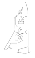
以下、本発明の実施形態について、添付図面を参照して説明する。図1は、第1実施形態におけるパチンコ機10の正面図であり、図2はパチンコ機10の遊技盤13の正面図であり、図3はパチンコ機10の後面図である。
<First Embodiment>
Embodiments of the present invention will be described below with reference to the accompanying drawings. FIG. 1 is a front view of a pachinko machine 10 according to the first embodiment, FIG. 2 is a front view of a game board 13 of the pachinko machine 10, and FIG. 3 is a rear view of the pachinko machine 10.

図1に示すように、パチンコ機10は、略矩形状に組み合わせた木枠により外殻が形成される外枠11と、その外枠11と略同一の外形形状に形成され外枠11に対して開閉可能に支持された内枠12とを備えている。外枠11には、内枠12を支持するために正面視(図1参照)左側の上下2カ所に金属製のヒンジ18が取り付けられ、そのヒンジ18が設けられた側を開閉の軸として内枠12が正面手前側へ開閉可能に支持されている。   As shown in FIG. 1, the pachinko machine 10 includes an outer frame 11 in which an outer shell is formed by a wooden frame combined in a substantially rectangular shape, and an outer shape that is substantially the same as the outer frame 11. And an inner frame 12 supported to be openable and closable. In order to support the inner frame 12, metal hinges 18 are attached to the outer frame 11 at two upper and lower portions on the left side when viewed from the front (see FIG. 1), and the side on which the hinge 18 is provided is used as an opening / closing axis. The frame 12 is supported so as to be openable and closable to the front front side.

内枠12には、多数の釘や入賞口63,64等を有する遊技盤13(図2参照)が裏面側から着脱可能に装着される。この遊技盤13の正面を球(遊技球)が流下することにより弾球遊技が行われる。なお、内枠12には、球を遊技盤13の正面領域に発射する球発射ユニット112a(図17参照)やその球発射ユニット112aから発射された球を遊技盤13の正面領域まで誘導する発射レール(図示せず)等が取り付けられている。   A game board 13 (see FIG. 2) having a large number of nails, winning holes 63, 64, and the like is detachably mounted on the inner frame 12 from the back side. A ball ball game is played when a ball (game ball) flows down the front of the game board 13. The inner frame 12 has a ball launch unit 112a (see FIG. 17) that launches a ball to the front area of the game board 13 and a shot that guides the ball launched from the ball launch unit 112a to the front area of the game board 13. A rail (not shown) or the like is attached.

内枠12の正面側には、その正面上側を覆う正面枠14と、その下側を覆う下皿ユニット15とが設けられている。正面枠14及び下皿ユニット15を支持するために正面視(図1参照)左側の上下2カ所に金属製のヒンジ19が取り付けられ、そのヒンジ19が設けられた側を開閉の軸として正面枠14及び下皿ユニット15が正面手前側へ開閉可能に支持されている。なお、内枠12の施錠と正面枠14の施錠とは、シリンダ錠20の鍵穴21に専用の鍵を差し込んで所定の操作を行うことでそれぞれ解除される。   On the front side of the inner frame 12, a front frame 14 that covers the front upper side and a lower dish unit 15 that covers the lower side are provided. In order to support the front frame 14 and the lower plate unit 15, metal hinges 19 are attached to two upper and lower portions on the left side when viewed from the front (see FIG. 1), and the side on which the hinges 19 are provided is used as an opening / closing axis. 14 and the lower pan unit 15 are supported so as to be openable and closable toward the front front side. The locking of the inner frame 12 and the locking of the front frame 14 are respectively released by inserting a dedicated key into the key hole 21 of the cylinder lock 20 and performing a predetermined operation.

正面枠14は、装飾用の樹脂部品や電気部品等を組み付けたものであり、その略中央部には略楕円形状に開口形成された窓部14cが設けられている。正面枠14の裏面側には2枚の板ガラスを有するガラスユニット16が配設され、そのガラスユニット16を介して遊技盤13の正面がパチンコ機10の正面側に視認可能となっている。   The front frame 14 is an assembly of decorative resin parts, electrical parts, and the like, and a window part 14c that is formed in an approximately elliptical shape is provided at a substantially central part thereof. A glass unit 16 having two plate glasses is disposed on the back side of the front frame 14, and the front of the game board 13 can be visually recognized on the front side of the pachinko machine 10 through the glass unit 16.

正面枠14には、球を貯留する上皿17が正面側へ張り出して上面を開放した略箱状に形成されており、この上皿17に賞球や貸出球などが排出される。上皿17の底面は正面視(図1参照)右側に下降傾斜して形成され、その傾斜により上皿17に投入された球が球発射ユニット112a(図17参照)へと案内される。また、上皿17の上面には、枠ボタン22が設けられている。この枠ボタン22は、例えば、第3図柄表示装置81(図2参照)で表示される演出のステージを変更したり、スーパーリーチの演出内容を変更したりする場合などに、遊技者により操作される。   On the front frame 14, an upper plate 17 that stores balls is formed in a substantially box shape that protrudes to the front side and opens the upper surface, and prize balls, rental balls, and the like are discharged to the upper plate 17. The bottom surface of the upper plate 17 is formed to be inclined downward to the right when viewed from the front (see FIG. 1), and the ball thrown into the upper plate 17 is guided to the ball launch unit 112a (see FIG. 17) by the inclination. A frame button 22 is provided on the upper surface of the upper plate 17. The frame button 22 is operated by the player when, for example, changing the stage of the effect displayed on the third symbol display device 81 (see FIG. 2) or changing the contents of the effect of super reach. The

正面枠14には、その周囲(例えばコーナー部分)に各種ランプ等の発光手段が設けられている。これら発光手段は、大当たり時や所定のリーチ時等における遊技状態の変化に応じて、点灯又は点滅することにより発光態様が変更制御され、遊技中の演出効果を高める役割を果たす。窓部14cの周縁には、LED等の発光手段を内蔵した電飾部29〜33が設けられている。パチンコ機10においては、これら電飾部29〜33が大当たりランプ等の演出ランプとして機能し、大当たり時やリーチ演出時等には内蔵するLEDの点灯や点滅によって各電飾部29〜33が点灯または点滅して、大当たり中である旨、或いは大当たり一歩手前のリーチ中である旨が報知される。また、正面枠14の正面視(図1参照)左上部には、LED等の発光手段が内蔵され賞球の払い出し中とエラー発生時とを表示可能な表示ランプ34が設けられている。   The front frame 14 is provided with light emitting means such as various lamps around the periphery (for example, a corner portion). These light emitting means play a role of enhancing the effect of the game during the game by changing or controlling the light emission mode by turning on or blinking according to the change of the gaming state at the time of big hit or predetermined reach. On the peripheral edge of the window portion 14c, there are provided electric decoration portions 29 to 33 incorporating light emitting means such as LEDs. In the pachinko machine 10, these lighting parts 29 to 33 function as effect lamps such as jackpot lamps, and the lighting parts 29 to 33 are turned on by lighting or blinking of the built-in LEDs at the time of jackpot or reach effects. Alternatively, it blinks to notify that the jackpot is being hit or that the reach is one step before the jackpot. Further, in the upper left part of the front frame 14 as viewed from the front (see FIG. 1), there is provided a display lamp 34 which has a built-in light emitting means such as an LED and can display when a prize ball is being paid out and when an error occurs.

また、右側の電飾部32下側には、正面枠14の裏面側を視認できるように裏面側より透明樹脂を取り付けて小窓35が形成され、遊技盤13正面の貼着スペースK1(図2参照)に貼付される証紙等がパチンコ機10の正面から視認可能とされている。また、パチンコ機10においては、より煌びやかさを醸し出すために、電飾部29〜33の周りの領域にクロムメッキを施したABS樹脂製のメッキ部材36が取り付けられている。   In addition, a small window 35 is formed by attaching a transparent resin from the back surface side so that the back surface side of the front frame 14 can be visually recognized, on the lower side of the right illumination part 32, and a sticking space K1 on the front surface of the game board 13 (FIG. 2) is visible from the front of the pachinko machine 10. In addition, in the pachinko machine 10, a plated member 36 made of ABS resin that is chrome-plated is attached to an area around the electric decoration parts 29 to 33 in order to bring out more gorgeousness.

窓部14cの下方には、貸球操作部40が配設されている。貸球操作部40には、度数表示部41と、球貸しボタン42と、返却ボタン43とが設けられている。パチンコ機10の側方に配置されるカードユニット(球貸しユニット)(図示せず)に紙幣やカード等を投入した状態で貸球操作部40が操作されると、その操作に応じて球の貸出が行われる。具体的には、度数表示部41はカード等の残額情報が表示される領域であり、内蔵されたLEDが点灯して残額情報として残額が数字で表示される。球貸しボタン42は、カード等(記録媒体)に記録された情報に基づいて貸出球を得るために操作されるものであり、カード等に残額が存在する限りにおいて貸出球が上皿17に供給される。返却ボタン43は、カードユニットに挿入されたカード等の返却を求める際に操作される。なお、カードユニットを介さずに球貸し装置等から上皿17に球が直接貸し出されるパチンコ機、いわゆる現金機では貸球操作部40が不要となるが、この場合には、貸球操作部40の設置部分に飾りシール等を付加して部品構成は共通のものとしても良い。カードユニットを用いたパチンコ機と現金機との共通化を図ることができる。   A ball rental operation unit 40 is disposed below the window 14c. The ball lending operation unit 40 is provided with a frequency display unit 41, a ball lending button 42, and a return button 43. When the ball lending operation unit 40 is operated in a state where a bill or a card is inserted into a card unit (ball lending unit) (not shown) arranged on the side of the pachinko machine 10, Loans are made. Specifically, the frequency display unit 41 is an area in which the remaining amount information such as a card is displayed, and the built-in LED is lit to display the remaining amount as the remaining amount information. The ball lending button 42 is operated to obtain a lending ball based on information recorded on a card or the like (recording medium), and the lending ball is supplied to the upper plate 17 as long as there is a remaining amount on the card or the like. Is done. The return button 43 is operated when requesting the return of a card or the like inserted into the card unit. In addition, in a pachinko machine in which a ball is lent directly to the upper plate 17 from a ball lending device or the like without using a card unit, a so-called cash machine does not require the ball lending operation unit 40. In this case, the ball lending operation unit 40 It is also possible to add a decorative seal or the like to the installation portion of the parts so that the component configuration is common. A pachinko machine using a card unit and a cash machine can be shared.

上皿17の下側に位置する下皿ユニット15には、その中央部に上皿17に貯留しきれなかった球を貯留するための下皿50が上面を開放した略箱状に形成されている。下皿50の右側には、球を遊技盤13の正面へ打ち込むために遊技者によって操作される操作ハンドル51が配設される。   In the lower plate unit 15 located on the lower side of the upper plate 17, a lower plate 50 for storing a ball that could not be stored in the upper plate 17 is formed in a substantially box shape having an open upper surface. Yes. On the right side of the lower plate 50, an operation handle 51 that is operated by a player to drive a ball into the front of the game board 13 is disposed.

操作ハンドル51の内部には、球発射ユニット112aの駆動を許可するためのタッチセンサ51aと、押下操作している期間中には球の発射を停止する発射停止スイッチ51bと、操作ハンドル51の回動操作量(回動位置)を電気抵抗の変化により検出する可変抵抗器(図示せず)などが内蔵されている。操作ハンドル51が遊技者によって右回りに回動操作されると、タッチセンサ51aがオンされると共に可変抵抗器の抵抗値が回動操作量に対応して変化し、その可変抵抗器の抵抗値に対応した強さ(発射強度)で球が発射され、これにより遊技者の操作に対応した飛び量で遊技盤13の正面へ球が打ち込まれる。また、操作ハンドル51が遊技者により操作されていない状態においては、タッチセンサ51aおよび発射停止スイッチ51bがオフとなっている。   Inside the operation handle 51, a touch sensor 51a for permitting driving of the ball launch unit 112a, a launch stop switch 51b for stopping the launch of the ball during the pressing operation, and a rotation of the operation handle 51. A variable resistor (not shown) that detects the amount of movement (rotation position) based on a change in electrical resistance is incorporated. When the operation handle 51 is rotated clockwise by the player, the touch sensor 51a is turned on and the resistance value of the variable resistor changes in accordance with the amount of rotation operation. The resistance value of the variable resistor The ball is fired with a strength corresponding to (launch strength), and the ball is driven into the front of the game board 13 with a jump amount corresponding to the player's operation. Further, when the operation handle 51 is not operated by the player, the touch sensor 51a and the firing stop switch 51b are turned off.

下皿50の正面下方部には、下皿50に貯留された球を下方へ排出する際に操作するための球抜きレバー52が設けられている。この球抜きレバー52は、常時、右方向に付勢されており、その付勢に抗して左方向へスライドさせることにより、下皿50の底面に形成された底面口が開口して、その底面口から球が自然落下して排出される。この球抜きレバー52の操作は、通常、下皿50の下方に下皿50から排出された球を受け取る箱(一般に「千両箱」と称される)を置いた状態で行われる。下皿50の右方には、上述したように操作ハンドル51が配設され、下皿50の左方には灰皿53が取り付けられている。   In the lower part of the front of the lower plate 50, a ball removal lever 52 is provided for operating when the balls stored in the lower plate 50 are discharged downward. The ball removal lever 52 is always urged in the right direction. By sliding the ball release lever 52 in the left direction against the urge, the bottom opening formed in the bottom surface of the lower plate 50 is opened. A ball naturally falls from the bottom opening and is discharged. The operation of the ball removal lever 52 is normally performed in a state where a box (generally referred to as “a thousand box”) for receiving the balls discharged from the lower plate 50 is placed below the lower plate 50. As described above, the operation handle 51 is disposed on the right side of the lower plate 50, and the ashtray 53 is attached on the left side of the lower plate 50.

図2に示すように、遊技盤13は、正面視略正方形状に切削加工したベース板60に、球案内用の多数の釘(図示せず)や風車(可動部材310を図示し、その他は図示せず)の他、レール61,62、一般入賞口63、第1入球口64、第2入球口640、第1可変入賞装置65、第2可変入賞装置650、普通入球口(スルーゲート)67、可変表示装置ユニット80、貯留装置600等を組み付けて構成され、その周縁部が内枠12(図1参照)の裏面側に取り付けられる。ベース板60は光透過性の樹脂材料からなり、その正面側からベース板60の後面側に配設された各種構造体を遊技者に視認させることが可能に形成される。一般入賞口63、第1入球口64、第2入球口640、第1可変入賞装置65、第2可変入賞装置650、可変表示装置ユニット80、貯留装置600は、ルータ加工によってベース板60に形成された貫通穴に配設され、遊技盤13の正面側からタッピングネジ等により固定されている。   As shown in FIG. 2, the game board 13 has a base plate 60 cut into a substantially square shape when viewed from the front, a large number of balls for nails (not shown) and a windmill (movable member 310 are shown, and the others are (Not shown), rails 61 and 62, general winning port 63, first winning port 64, second winning port 640, first variable winning device 65, second variable winning device 650, normal winning port ( The through gate) 67, the variable display device unit 80, the storage device 600, and the like are assembled, and the peripheral edge thereof is attached to the back side of the inner frame 12 (see FIG. 1). The base plate 60 is made of a light-transmitting resin material, and is formed so that the player can visually recognize various structures disposed on the rear surface side of the base plate 60 from the front side. The general winning port 63, the first winning port 64, the second winning port 640, the first variable winning device 65, the second variable winning device 650, the variable display device unit 80, and the storage device 600 are obtained by the base plate 60 by router processing. The game board 13 is fixed from the front side of the game board 13 with a tapping screw or the like.

遊技盤13の正面中央部分は、正面枠14の窓部14c(図1参照)を通じて内枠12の正面側から視認することができる。以下に、主に図2を参照して、遊技盤13の構成について説明する。   The front center portion of the game board 13 can be viewed from the front side of the inner frame 12 through the window portion 14c of the front frame 14 (see FIG. 1). The configuration of the game board 13 will be described below mainly with reference to FIG.

遊技盤13の正面には、帯状の金属板を略円弧状に屈曲加工して形成した外レール62が植立され、その外レール62の内側位置には外レール62と同様に帯状の金属板で形成した円弧状の内レール61が植立される。この内レール61と外レール62とにより遊技盤13の正面外周が囲まれ、遊技盤13とガラスユニット16(図1参照)とにより前後が囲まれることにより、遊技盤13の正面には、球の挙動により遊技が行われる遊技領域が形成される。遊技領域は、遊技盤13の正面であって2本のレール61,62とレール間を繋ぐ樹脂製の外縁部材73とにより区画して形成される領域(入賞口等が配設され、発射された球が流下する領域)である。   An outer rail 62 formed by bending a band-shaped metal plate into a substantially arc shape is planted on the front surface of the game board 13. The arc-shaped inner rail 61 formed by the above is planted. The inner periphery of the game board 13 is surrounded by the inner rail 61 and the outer rail 62, and the front and rear are surrounded by the game board 13 and the glass unit 16 (see FIG. 1). A game area in which a game is played is formed by the behavior of. The game area is an area formed in front of the game board 13 and defined by the two rails 61 and 62 and a resin outer edge member 73 connecting the rails (a winning opening is provided and fired). Area where the falling sphere flows).

2本のレール61,62は、球発射ユニット112a(図17参照)から発射された球を遊技盤13上部へ案内するために設けられたものである。内レール61の先端部分(図2の左上部)には戻り球防止部材68が取り付けられ、一旦、遊技盤13の上部へ案内された球が再度球案内通路内に戻ってしまうといった事態が防止される。外レール62の先端部(図2の右上部)には、球の最大飛翔部分に対応する位置に返しゴム69が取り付けられ、所定以上の勢いで発射された球は、返しゴム69に当たって、勢いが減衰されつつ中央部側へ跳ね返される。また、内レール61の右下側の先端部と外レール62の右上側の先端部との間には、レール間を繋ぐ円弧を内面側に設けて形成された樹脂製の円弧部材70がベース板60に打ち込んで固定されている。   The two rails 61 and 62 are provided to guide the ball fired from the ball launch unit 112a (see FIG. 17) to the upper part of the game board 13. A return ball preventing member 68 is attached to the front end portion of the inner rail 61 (upper left portion in FIG. 2) to prevent the ball once guided to the upper portion of the game board 13 from returning to the ball guide path again. Is done. A return rubber 69 is attached to the tip of the outer rail 62 (upper right part in FIG. 2) at a position corresponding to the maximum flying portion of the sphere, and the ball launched at a predetermined momentum or more hits the return rubber 69 and gains momentum. Is bounced back to the center while being attenuated. A resin arc member 70 formed by providing an arc connecting the rails on the inner surface side between the lower right end of the inner rail 61 and the upper right end of the outer rail 62 is a base. The plate 60 is driven and fixed.

本パチンコ機10では、第1入球口64、および第2入球口640へ入賞があったことを契機として特別図柄(第1図柄)の抽選が行われ、球が普通入球口67を通過した場合に普通図柄(第2図柄)の抽選が行われる。第1入球口64、および第2入球口640への入球に対して行われる特別図柄の抽選では、特別図柄の大当たりか否かの当否判定が行われると共に、特別図柄の大当たりと判定された場合にはその大当たり種別の判定も行われる。なお、説明の便宜上、第1入球口64への入球に対して行われる特別図柄の抽選を「特別図柄1の抽選」と称し、第2入球口640への入球に対して行われる特別図柄の抽選を「特別図柄2の抽選」と称する。   In the pachinko machine 10, a special symbol (first symbol) is drawn when the first entrance 64 and the second entrance 640 are won, and the ball enters the normal entrance 67. When it passes, the lottery of the normal symbol (second symbol) is performed. In the special symbol lottery performed for the entrance to the first entrance 64 and the second entrance 640, whether or not the special symbol is a big hit is determined, and it is determined that the special symbol is a big hit. In the case of being made, the jackpot type is also determined. For convenience of explanation, the special symbol lottery performed for the entrance to the first entrance 64 is referred to as “special design 1 lottery” and is performed for the entrance to the second entrance 640. The special symbol lottery to be called is referred to as “special symbol 2 lottery”.

特別図柄の大当たりになると、パチンコ機10が特別遊技状態へ移行すると共に、通常時には閉鎖されている第1特定入賞口65a、または第2特定入賞口650aが所定時間(例えば、30秒経過するまで、或いは、球が10個入賞するまで)開放される動作が15回(15ラウンド)繰り返される。より具体的には、1〜11ラウンド、および13〜15ラウンドでは、第1特定入賞口65aが所定時間(例えば、30秒経過するまで、或いは、球が10個入賞するまで)開放され、12ラウンドでは第2特定入賞口650aが所定時間(例えば、30秒経過するまで、或いは、球が10個入賞するまで)開放される。その結果、その第1特定入賞口65a、および第2特定入賞口650aに多量の球が入賞するので、通常時より多量の賞球の払い出しが行われる。   When the special symbol is a big hit, the pachinko machine 10 shifts to a special game state, and the first specific winning port 65a or the second specific winning port 650a that is normally closed is kept for a predetermined time (for example, 30 seconds). Alternatively, the releasing operation is repeated 15 times (15 rounds) until 10 balls are won. More specifically, in the first to eleventh rounds and the thirteenth to fifteenth rounds, the first specific winning opening 65a is opened for a predetermined time (for example, until 30 seconds have elapsed or ten balls have been won). In the round, the second specific winning opening 650a is opened for a predetermined time (for example, until 30 seconds have elapsed or 10 balls have been won). As a result, a large amount of balls are awarded to the first specific winning port 65a and the second specific winning port 650a, so that a larger amount of winning balls are paid out than usual.

また、第2可変入賞装置650の内部には、特別遊技状態の終了後に付与される大当たり終了後の付加価値を決定するための2種類の入球口(確変入球口654、および通常入球口655)が設けられている(図15参照)。詳細については後述するが、特別遊技状態において確変入球口654に対して球が入球した場合は、大当たり終了後の付加価値として「特別図柄の高確率状態」が付与される。一方、特別遊技状態中に一度も確変入球口654へと球が入球しなかった場合は、大当たり終了後の付加価値として「普通図柄の時短状態」が付与される。なお、特別図柄の大当たり種別としては、「大当たりA」、「大当たりB」の2種類が設けられている(図18(b)参照)。詳細については後述するが、大当たり種別によって、第2特定入賞口650aの開放パターンが異なって構成されており、確変入球口654への球の入球しやすさを異ならせている。   The second variable winning device 650 includes two types of entrances (probability entrance entrance 654 and normal entrance) for determining the added value after the jackpot given after the end of the special gaming state. Mouth 655) is provided (see FIG. 15). Although details will be described later, when a ball enters the probability variation entrance 654 in a special game state, a “special symbol high probability state” is given as an added value after the jackpot is over. On the other hand, if the ball has never entered the probability variation entrance 654 during the special game state, “ordinary symbol time-short state” is given as the added value after the jackpot. Note that there are two types of special symbol jackpot types, “Big Jack A” and “Big Jack B” (see FIG. 18B). Although the details will be described later, the opening pattern of the second specific winning opening 650a is configured differently depending on the type of jackpot, and the ease of entering the ball into the probability changing entrance 654 is varied.

特別図柄(第1図柄)の抽選が行われると、第1図柄表示装置37において特別図柄の変動表示が開始されて、所定時間(例えば、11秒〜60秒など)が経過した後に、抽選結果を示す特別図柄が停止表示される。第1図柄表示装置37において変動表示が行われている間に球が第1入球口64、または第2入球口640へと入球すると、その入球回数は入球口の種別毎にそれぞれ最大4回まで保留され、その保留球数が第1図柄表示装置37により示されると共に、第3図柄表示装置81においても示される。第1図柄表示装置37において変動表示が終了した場合に、第1入球口64についての保留球数(特別図柄1の保留球数)、または第2入球口640についての保留球数(特別図柄2の保留球数)が残っていれば、次の特別図柄の抽選が行われると共に、その抽選に応じた変動表示が開始される。なお、特別図柄1の保留球数と特別図柄2の保留球数が共に残っている場合は、特別図柄2の保留球に基づく抽選が優先的に実行される。   When the special symbol (the first symbol) is drawn, the special symbol variation display is started on the first symbol display device 37, and after a predetermined time (for example, 11 seconds to 60 seconds) has elapsed, the lottery result A special symbol indicating is stopped and displayed. When a ball enters the first entrance 64 or the second entrance 640 while the variable display is being performed on the first symbol display device 37, the number of entrances is different for each type of entrance. Each of the balls is held up to four times, and the number of balls held is indicated by the first symbol display device 37 and also by the third symbol display device 81. When the variable display is finished on the first symbol display device 37, the number of reserved balls for the first entrance 64 (the number of reserved balls of the special symbol 1) or the number of reserved balls for the second entrance 640 (special If the number of reserved balls of symbol 2) remains, the lottery of the next special symbol is performed and the variable display corresponding to the lottery is started. When both the number of reserved balls of special symbol 1 and the number of reserved balls of special symbol 2 remain, the lottery based on the reserved balls of special symbol 2 is preferentially executed.

一方、普通入球口67における球の通過に対して行われる普通図柄の抽選では、普通図柄の当たりか否かの当否判定が行われる。普通図柄の当たりになると、所定時間(例えば、0.2秒または1秒)だけ第2入球口640に付随する電動役物640aが開放され、第2入球口640へ球が入球し易い状態になる。つまり、普通図柄の当たりになると、球が第2入球口640へ入球し易くなり、その結果、特別図柄の抽選が行われ易くなる。   On the other hand, in the normal symbol lottery performed for the passage of the ball at the normal entrance 67, whether or not the normal symbol is hit is determined. When hitting the normal symbol, the electric accessory 640a attached to the second entrance 640 is opened for a predetermined time (for example, 0.2 seconds or 1 second), and the ball enters the second entrance 640. Easy state. That is, when the normal symbol is hit, it becomes easy for the ball to enter the second entrance 640, and as a result, it becomes easy to draw a special symbol.

また、普通図柄(第2図柄)の抽選が行われると、第2図柄表示装置83において普通図柄の変動表示が開始されて、所定時間(例えば、3秒や30秒など)が経過した後に、抽選結果を示す普通図柄が停止表示される。第2図柄表示装置83において変動表示が行われている間に球が普通入球口67を通過すると、その通過回数は最大4回まで保留され、その保留球数が第1図柄表示装置37により表示されると共に、第2図柄保留ランプ84においても示される。第2図柄表示装置83において変動表示が終了した場合に、普通入球口67についての保留球数が残っていれば、次の普通図柄の抽選が行われると共に、その抽選に応じた変動表示が開始される。   In addition, when the normal symbol (the second symbol) is drawn, the normal symbol variation display is started on the second symbol display device 83, and after a predetermined time (for example, 3 seconds or 30 seconds) has elapsed, A normal symbol indicating the lottery result is stopped and displayed. If the ball passes through the normal entrance 67 while the variable display is being performed on the second symbol display device 83, the number of passages is suspended up to a maximum of four times, and the number of retained balls is retained by the first symbol display device 37. In addition to being displayed, it is also shown in the second symbol holding lamp 84. When the variable display is completed in the second symbol display device 83, if the number of reserved balls for the normal entrance 67 remains, the next normal symbol is drawn and the variable display corresponding to the lottery is displayed. Be started.

「大当たりA」、および「大当たりB」になるといずれも、ラウンド数が15ラウンドの特別遊技状態(15R大当たり)となる。また、特別遊技状態において、確変入球口654へと球が入球すると、大当たり終了後の付加価値として、その大当たり終了後から次に大当たりとなるまでの間、パチンコ機10が特別図柄の高確率状態(特別図柄の確変中)へ移行する。一方、特別遊技状態において1度も確変入球口654へと球が入球しなかった場合は、大当たり終了後の付加価値として、その大当たり終了後から特別図柄の抽選が100回終了するまでの間、普通図柄の時短状態へ移行する。なお、大当たり終了後に普通図柄の時短状態へと移行する場合は、あわせて特別図柄の低確率状態へと移行する。この特別図柄の低確率状態は、次に大当たりとなるまで継続する。なお、詳細については後述するが、「大当たりB」では、「大当たりA」に比較して、特別遊技状態中(大当たり状態中)に球を確変入球口654へと入球させやすくなる。即ち、「大当たりB」の方が大当たり終了後に特別図柄の確変状態へと移行しやすくなるので、大当たりの終了後に短い間隔で再度大当たりとなりやすくなる。よって、「大当たりB」の方が、「大当たりA」よりも遊技者にとって有利な大当たりとなる。   In both cases of “big hit A” and “big hit B”, the number of rounds becomes a special game state with 15 rounds (15R big hit). Further, in a special game state, when a ball enters the probability variation entrance 654, as a value added after the jackpot ends, the pachinko machine 10 has a special symbol high from the end of the jackpot until the next jackpot. Moves to the probability state (during special symbol change). On the other hand, if the ball never enters the probability variation entrance 654 in the special game state, as a value added after the jackpot, the lottery of the special symbol is completed 100 times after the jackpot ends. In the meantime, it shifts to the short time state of normal symbols. In addition, when it shifts to the short time state of the normal symbol after the jackpot ends, it shifts to the low probability state of the special symbol together. This low probability state of the special symbol continues until the next big hit. Although details will be described later, in the “big hit B”, it becomes easier to make the ball enter the probability variation entrance 654 in the special game state (during the big hit state) as compared to the “big hit A”. That is, since “big hit B” is more likely to shift to the probability change state of the special symbol after the big hit, the big hit is likely to be made again at short intervals after the big hit. Therefore, “big hit B” is a big hit that is more advantageous to the player than “big hit A”.

ここで、「特別図柄の高確率状態」とは、大当たり終了後に付加価値としてその後の大当たり確率がアップした状態、いわゆる確率変動中(確変中)の時をいい、換言すれば、特別遊技状態へ移行し易い遊技の状態のことである。本実施形態における特別図柄の高確率状態(特別図柄の確変中)は、普通図柄(第2図柄)の当たり確率がアップして第2入球口640へ球が入賞し易い遊技の状態を含む。一方、「特別図柄の低確率状態」とは、特別図柄の確変中でない時をいい、大当たり確率が通常の状態、即ち、特別図柄の確変中よりも大当たり確率が低い状態をいう。また、普通図柄の時短状態(時短中)とは、普通図柄の当たり確率がアップして第2入球口640へ球が入賞し易い遊技の状態のことをいう。一方、通常状態とは、特別図柄の確変中でも普通図柄の時短中でもない遊技の状態(大当たり確率も普通図柄(第2図柄)の当たり確率もアップしていない状態)である。   Here, the “high probability state of a special symbol” means a state in which the jackpot probability thereafter increases as added value after the jackpot ends, that is, when the probability is changing (probability is changing), in other words, to the special gaming state. It is a game state that is easy to shift. The high probability state of the special symbol (during the special symbol change) in the present embodiment includes a game state in which the hit probability of the normal symbol (second symbol) is increased and the ball is likely to win the second entrance 640. . On the other hand, the “special symbol low probability state” means a time when the special symbol is not being probable, and a state where the jackpot probability is normal, that is, a state where the jackpot probability is lower than that during the special symbol probabilistic change. In addition, the normal symbol time-short state (short time medium) means a game state in which the normal symbol hit probability is increased and the ball is likely to win the second entrance 640. On the other hand, the normal state is a game state (a state where neither the big hit probability nor the normal symbol (second symbol) has been increased) that is neither a probability change of a special symbol nor a short time of a normal symbol.

特別図柄の確変中や、普通図柄の時短中では、普通図柄の当たり確率がアップするだけではなく、第2入球口640に付随する電動役物640aが開放される時間も変更され、通常状態に比較して長い時間が設定される。電動役物640aが開放された状態(開放状態)にある場合は、その電動役物640aが閉鎖された状態(閉鎖状態)にある場合と比較して、第2入球口640へ球が入賞しやすい状態となる。よって、特別図柄の確変中や普通図柄の時短中は、第2入球口640へ球が入球し易い状態となる。即ち、特別図柄の抽選が行われやすくなる。   During the probable change of the special symbol or during the short time of the normal symbol, not only the probability of hitting the normal symbol is increased, but also the time when the electric accessory 640a attached to the second entrance 640 is opened is changed, and the normal state A longer time is set in comparison with. When the electric accessory 640a is in an opened state (open state), the ball wins the second entrance 640 in comparison with the case where the electric accessory 640a is in a closed state (closed state). It becomes easy to do. Therefore, it becomes easy for the ball to enter the second entrance 640 during the special symbol change or the normal symbol time reduction. That is, it becomes easy to draw a special symbol.

なお、特別図柄の確変中や普通図柄の時短中において、第2入球口640に付随する電動役物640aの開放時間を変更するのではなく、または、その開放時間を変更することに加えて、普通図柄の当たりとなった場合における電動役物640aの開放回数を、通常状態よりも増やすように構成してもよい。また、特別図柄の確変中や普通図柄の時短中において、普通図柄(第2図柄)の当たり確率は変更せず、第2入球口640に付随する電動役物640aが開放される時間、および電動役物640aの開放回数のうち少なくとも一方を変更するものとしてもよい。また、特別図柄の確変中や普通図柄の時短中において、第2入球口640に付随する電動役物640aが開放される時間や、電動役物640aの開放回数は変更せず、普通図柄(第2図柄)の当たり確率だけを、通常状態に比較してアップするように構成してもよい。   In addition, in addition to changing the opening time instead of changing the opening time of the electric accessory 640a associated with the second entrance 640 during the special symbol change or the normal symbol time reduction The number of times of opening of the electric accessory 640a when the normal symbol is hit may be increased more than the normal state. In addition, the probability of hitting the normal symbol (second symbol) is not changed during the probability change of the special symbol or the normal symbol, and the time when the electric accessory 640a associated with the second entrance 640 is opened, and It is good also as what changes at least one among the frequency | counts of opening of the electrically-driven accessory 640a. In addition, during the change of the probability of the special symbol or during the short time of the normal symbol, the time for opening the electric accessory 640a associated with the second entrance 640 and the number of times the electric accessory 640a is opened are not changed. Only the hit probability of the second pattern) may be increased as compared with the normal state.

本実施形態では、特別遊技状態の終了後に特別図柄の確変状態が付与される場合は、その特別図柄の確変状態が次の大当たりまで継続するように構成したが、これに限られるものではなく、回数を限ってもよい。具体的には、例えば、特別遊技状態が終了してから特別図柄の抽選が10回終了するまで特別図柄の確変状態(高確率状態)が付与され、特別図柄の抽選が10回終了して以降は通常状態に設定されるように構成してもよい。また、特別図柄の確変状態となる回数は10回に限られず、任意に定めてもよい。同様に、本実施形態では、特別遊技状態において確変入球口654へと球が入球しなかった場合に、特別図柄の抽選が100回終了するまで普通図柄の時短状態となるように構成されているが、普通図柄の時短期間は100回に限られず、任意に定めてもよい。   In the present embodiment, when the probability variation state of the special symbol is granted after the special gaming state ends, the probability variation state of the special symbol is configured to continue until the next jackpot, but is not limited to this, The number of times may be limited. Specifically, for example, a special symbol probability change state (high probability state) is given until the special symbol lottery ends 10 times after the special gaming state ends, and after the special symbol lottery ends 10 times. May be configured to be set in a normal state. In addition, the number of times that the special symbol is changed to a certain state is not limited to 10 and may be arbitrarily determined. Similarly, in the present embodiment, when the ball does not enter the probability variation entrance 654 in the special game state, the normal symbol is shortened until the special symbol lottery is completed 100 times. However, the short time period of the normal symbol is not limited to 100 times and may be arbitrarily determined.

遊技領域の正面視右側上部(図2の右側上部)には、発光手段である複数の発光ダイオード(以下、「LED」と略す)37aと7セグメント表示器37bとが設けられた第1図柄表示装置37が配設されている。第1図柄表示装置37は、後述する主制御装置110で行われる各制御に応じた表示がなされるものであり、主にパチンコ機10の遊技状態の表示が行われる。複数のLED37aは、第1入球口64、または第2入球口640への入球(始動入賞)に伴って行われる特別図柄の抽選が実行中であるか否かを点灯状態により示すことによって変動表示を行ったり、変動終了後の停止図柄として、その特別図柄の抽選結果に応じた特別図柄(第1図柄)を点灯状態により示したり、第1入球口64に入球された球のうち変動が未実行である球(保留球)の数である保留球数を点灯状態により示すものである。   A first symbol display in which a plurality of light emitting diodes (hereinafter abbreviated as “LED”) 37a and a 7-segment display 37b, which are light emitting means, are provided in the upper right part of the gaming area when viewed from the front (upper right part of FIG. 2). A device 37 is provided. The first symbol display device 37 displays information corresponding to each control performed by the main control device 110 described later, and mainly displays the gaming state of the pachinko machine 10. The plurality of LEDs 37a indicate by lighting whether or not a special symbol lottery performed in accordance with the entrance to the first entrance 64 or the second entrance 640 (start winning prize) is being executed. As a stop symbol after the end of the variation, the special symbol (first symbol) corresponding to the lottery result of the special symbol is indicated by the lighting state, or the ball that has entered the first entrance 64 The number of reserved spheres, which is the number of spheres that have not been changed (reserved spheres), is indicated by the lighting state.

この第1図柄表示装置37において特別図柄(第1図柄)の変動表示が行われている間に球が第1入球口64、または第2入球口640へと入球した場合、その入球回数は入球口の種別毎にそれぞれ最大4回まで保留され、その保留球数は第1図柄表示装置37により示されると共に、第3図柄表示装置81においても示される。なお、本実施形態においては、第1入球口64、および第2入球口640への入球は、それぞれ最大4回まで保留されるように構成したが、最大保留回数は4回に限定されるものでなく、3回以下、又は、5回以上の回数(例えば、8回)に設定しても良い。   If a ball enters the first entrance 64 or the second entrance 640 while the special symbol (first symbol) is being displayed on the first symbol display device 37, the entry The number of balls is held for a maximum of 4 times for each type of entrance, and the number of held balls is indicated by the first symbol display device 37 and also by the third symbol display device 81. In the present embodiment, the first entrance 64 and the second entrance 640 are configured to be suspended up to 4 times each, but the maximum number of suspensions is limited to 4 times. Instead, it may be set to 3 times or less, or 5 times or more (for example, 8 times).

7セグメント表示器37bは、大当たり中のラウンド数やエラー表示を行うものである。なお、LED37aは、それぞれのLEDの発光色(例えば、赤、緑、青)が異なるよう構成され、その発光色の組み合わせにより、少ないLEDでパチンコ機10の各種遊技状態(特別図柄の高確率状態や、普通図柄の時短中など)を表示することができる。また、LED37aには、変動終了後の停止図柄として特別図柄の抽選結果が大当たりであるか否かが示されるだけでなく、大当たりである場合はその大当たり種別(大当たりA、大当たりB)に応じた特別図柄(第1図柄)が示される。   The 7-segment display 37b displays the number of rounds that are a big hit and an error display. Note that the LEDs 37a are configured so that the emission colors (for example, red, green, and blue) of the respective LEDs are different, and depending on the combination of the emission colors, various gaming states of the pachinko machine 10 (high probability states of special symbols) And normal symbols, etc.). In addition, the LED 37a not only indicates whether or not the lottery result of the special symbol is a big hit as a stop symbol after the end of the fluctuation, but if it is a big hit, it corresponds to the big hit type (big hit A, big hit B) A special symbol (first symbol) is shown.

また、遊技領域には、球が入賞することにより5個から15個の球が賞球として払い出される複数の一般入賞口63が配設されている。また、遊技領域の中央部分には、可変表示装置ユニット80が配設されている。可変表示装置ユニット80には、液晶ディスプレイ(以下単に「表示装置」と略す)で構成された第3図柄表示装置81と、LEDで構成された第2図柄表示装置83とが設けられている。この可変表示装置ユニット80には、第3図柄表示装置81の外周を囲むようにして、センターフレーム86が配設されている。   The game area is provided with a plurality of general winning openings 63 through which 5 to 15 balls are paid out as winning balls when the balls win. In addition, a variable display device unit 80 is disposed in the central portion of the game area. The variable display device unit 80 is provided with a third symbol display device 81 composed of a liquid crystal display (hereinafter simply referred to as “display device”) and a second symbol display device 83 composed of LEDs. The variable display device unit 80 is provided with a center frame 86 so as to surround the outer periphery of the third symbol display device 81.

第3図柄表示装置81は、第1図柄表示装置37の表示に応じた装飾的な表示を行うものである。例えば、第1入球口64へ球が入球(始動入賞)すると、それをトリガとして、第1図柄表示装置37において特別図柄(第1図柄)の変動表示が実行される。更に、第3図柄表示装置81では、その特別図柄の変動表示に同期して、その特別図柄の変動表示に対応する第3図柄の変動表示が行われる。   The third symbol display device 81 performs a decorative display according to the display of the first symbol display device 37. For example, when a ball enters the first entrance 64 (start winning prize), a special symbol (first symbol) is displayed on the first symbol display device 37 as a trigger. Further, in the third symbol display device 81, the variation display of the third symbol corresponding to the variation display of the special symbol is performed in synchronization with the variation display of the special symbol.

第3図柄表示装置81は9インチサイズの大型の液晶ディスプレイで構成されるものであり、表示制御装置114(図17参照)によって表示内容が制御されることにより、例えば上、中、および下の3つの図柄列が表示される。各図柄列は複数の図柄(第3図柄)によって構成され、これらの第3図柄が図柄列毎に縦スクロールして第3図柄表示装置81の表示画面上にて第3図柄が可変表示されるようになっている。本実施形態の第3図柄表示装置81は、主制御装置110(図17参照)の制御に伴った遊技状態の表示が第1図柄表示装置37で行われるのに対して、その第1図柄表示装置37の表示に応じた装飾的な表示を行うものである。なお、液晶ディスプレイに代えて、例えばリール等を用いて第3図柄表示装置81を構成するようにしても良い。   The third symbol display device 81 is constituted by a large 9-inch liquid crystal display, and the display content is controlled by the display control device 114 (see FIG. 17), for example, the upper, middle, and lower Three symbol rows are displayed. Each symbol row is composed of a plurality of symbols (third symbol), and these three symbols are scrolled vertically for each symbol column, and the third symbol is variably displayed on the display screen of the third symbol display device 81. It is like that. In the third symbol display device 81 of the present embodiment, the display of the gaming state accompanying the control of the main control device 110 (see FIG. 17) is performed on the first symbol display device 37, whereas the first symbol display thereof. A decorative display corresponding to the display of the device 37 is performed. Instead of the liquid crystal display, the third symbol display device 81 may be configured using, for example, a reel.

ここで、図4〜図7を参照して、第3図柄表示装置81の表示内容について説明する。まず、図4は、第3図柄表示装置81の表示画面を説明するための図面であり、図4(a)は、表示画面の領域区分設定と有効ライン設定とを模式的に示した図であり、図4(b)は、実際の表示画面を例示した図である。   Here, with reference to FIGS. 4-7, the display content of the 3rd symbol display apparatus 81 is demonstrated. First, FIG. 4 is a diagram for explaining the display screen of the third symbol display device 81, and FIG. 4 (a) is a diagram schematically showing area segment setting and effective line setting of the display screen. FIG. 4B is a diagram illustrating an actual display screen.

第3図柄は、「0」から「9」の数字を付した10種類の主図柄により構成されている。各主図柄は、木箱よりなる後方図柄の上に「0」から「9」の数字を付して構成され、そのうち奇数番号(1,3,5,7,9)を付した主図柄は、木箱の前面ほぼ一杯に大きな数字が付加されている。これに対し、偶数番号(0,2,4,6,8)を付した主図柄は、木箱の前面ほぼ一杯にかんな、風呂敷、ヘルメット等のキャラクタを模した付属図柄が付加されており、付属図柄の右下側に偶数の数字が緑色で小さく、且つ、付属図柄の前側に表示されるように付加されている。   The third symbol is composed of ten kinds of main symbols with numbers from “0” to “9”. Each main symbol is composed of numbers from “0” to “9” on the rear symbol consisting of a wooden box, of which the main symbols with odd numbers (1, 3, 5, 7, 9) are A large number is added to almost the front of the wooden box. On the other hand, the main symbols with even numbers (0, 2, 4, 6, 8) have attached symbols that imitate characters such as furoshiki, helmet, etc., almost full front of the wooden box, An even number is small in green on the lower right side of the attached symbol and is added so as to be displayed on the front side of the attached symbol.

また、本実施形態のパチンコ機10においては、後述する主制御装置110(図17参照)により行われる特別図柄の抽選結果が大当たりであった場合に、同一の主図柄が揃う変動表示が行われ、その変動表示が終わった後に大当たりが発生するよう構成されている。一方、特別図柄の抽選結果が外れであった場合は、同一の主図柄が揃わない変動表示が行われる。   Moreover, in the pachinko machine 10 of the present embodiment, when the special symbol lottery result performed by the main control device 110 (see FIG. 17) described later is a big hit, the variable display in which the same main symbols are aligned is performed. The jackpot is configured to occur after the change display is finished. On the other hand, when the lottery result of the special symbol is out of place, the variable display in which the same main symbols are not arranged is performed.

例えば、特別図柄の抽選結果が「大当たりA」であれば、偶数番号である「0,2,4,6,8」が付加された主図柄が揃う変動表示が行われる。一方、「大当たりB」であれば、奇数番号も加えたすべての番号「0,1,2,3,4,5,6,7,8,9」のうちいずれかの番号が付加された主図柄が揃う変動表示が行われる。一方、特別図柄の抽選結果が外れであれば、同一番号の主図柄が揃わない変動表示が行われる。   For example, if the lottery result of the special symbol is “big hit A”, the variable display is performed in which the main symbols to which “0, 2, 4, 6, 8”, which are even numbers, are added are arranged. On the other hand, in the case of “big hit B”, any number among all the numbers “0, 1, 2, 3, 4, 5, 6, 7, 8, 9” including the odd number is added. Fluctuation display in which symbols are aligned is performed. On the other hand, if the lottery result of the special symbol is off, the variable display in which the main symbols of the same number are not aligned is performed.

図4(a)に示すように、第3図柄表示装置81の表示画面は、大きくは上下に2分割され、下側の2/3が第3図柄を変動表示する主表示領域Dm、それ以外の上側の1/3が予告演出、キャラクタおよび保留球数などを表示する副表示領域Dsとなっている。   As shown in FIG. 4 (a), the display screen of the third symbol display device 81 is roughly divided into two in the vertical direction, and the lower 2/3 is the main display area Dm for variably displaying the third symbol, and the others. The upper third is a sub display area Ds for displaying a notice effect, a character, the number of reserved balls, and the like.

主表示領域Dmは、左・中・右の3つの表示領域Dm1〜Dm3に区分けされており、その3つの表示領域Dm1〜Dm3に、それぞれ3つの図柄列Z1,Z2,Z3が表示される。各図柄列Z1〜Z3には、上述した第3図柄が規定の順序で表示される。即ち、各図柄列Z1〜Z3には、数字の昇順または降順に主図柄が配列され、図柄列Z1〜Z3毎に周期性をもって上から下へとスクロールして変動表示が行われる。特に、左図柄列Z1においては主図柄の数字が降順に現れるように配列され、中図柄列Z2及び右図柄列Z3においては主図柄の数字が昇順に現れるように配列されている。   The main display area Dm is divided into three display areas Dm1 to Dm3 of left, middle, and right, and three symbol rows Z1, Z2, and Z3 are displayed in the three display areas Dm1 to Dm3, respectively. In each symbol row Z1 to Z3, the above-described third symbols are displayed in a prescribed order. That is, the main symbols are arranged in ascending or descending numbers in the symbol rows Z1 to Z3, and the symbol rows Z1 to Z3 are scrolled from the top to the bottom with periodicity to perform the variable display. In particular, the left symbol row Z1 is arranged so that the numbers of the main symbols appear in descending order, and the middle symbol row Z2 and the right symbol row Z3 are arranged so that the numbers of the main symbols appear in ascending order.

また、主表示領域Dmには、図柄列Z1〜Z3毎に上・中・下の3段に第3図柄が表示される。この主表示領域Dmの中段部が有効ラインL1として設定されており、毎回の遊技に際して、左図柄列Z1→右図柄列Z3→中図柄列Z2の順に、有効ラインL1上に第3図柄が停止表示される。その第3図柄の停止時に有効ラインL1上に大当たり図柄の組合せ(本実施形態では、同一の主図柄の組合せ)で揃えば大当たりとして大当たり動画が表示される。   In the main display area Dm, the third symbols are displayed in the upper, middle, and lower three rows for each of the symbol rows Z1 to Z3. The middle part of the main display area Dm is set as the active line L1, and in each game, the third symbol stops on the effective line L1 in the order of the left symbol row Z1, the right symbol row Z3, and the middle symbol row Z2. Is displayed. If the combination of jackpot symbols (the same main symbol combination in this embodiment) is arranged on the effective line L1 when the third symbol is stopped, a jackpot moving image is displayed as a jackpot.

一方、副表示領域Dsは、主表示領域Dmよりも上方に横長に設けられており、さらに左右方向に3つの小領域Ds1〜Ds3に等区分されている。このうち、小領域Ds1は、第1入球口64、および第2入球口640へと入球した球のうち変動が未実行である球(保留球)の数である保留球数を表示する領域であり、小領域Ds2およびDs3は、予告演出画像を表示する領域である。   On the other hand, the sub display area Ds is horizontally long above the main display area Dm, and is further equally divided into three small areas Ds1 to Ds3 in the left-right direction. Among these, the small area Ds1 displays the number of held balls, which is the number of balls that have not been executed (holding balls) among the balls that have entered the first entrance 64 and the second entrance 640. The small areas Ds2 and Ds3 are areas for displaying the notice effect image.

実際の表示画面では、図4(b)に示すように、主表示領域Dmに第3図柄の主図柄が合計9個表示される。副表示領域Dsにおいては、右の小領域Ds3に動画が表示され、通常より大当たりへ遷移し易い状態であることが遊技者に示唆される。中央の小領域Ds2では、通常は、所定のキャラクタ710(本実施形態ではハチマキを付けた少年)が所定動作をし、時として所定動作とは別の特別な動作をしたり、別のキャラクタが現出する等して予告演出が行われる。   On the actual display screen, as shown in FIG. 4B, a total of nine main symbols of the third symbol are displayed in the main display area Dm. In the sub display area Ds, a moving image is displayed in the small area Ds3 on the right, and it is suggested to the player that the player is more likely to make a big hit than usual. In the central small area Ds2, a predetermined character 710 (a boy with a bee in this embodiment) usually performs a predetermined action and sometimes performs a special action different from the predetermined action, A notice effect is performed by appearing.

一方、第3図柄表示装置81(第1図柄表示装置37)にて変動表示が行われている間に球が第1入球口64、または第2入球口640へと入球した場合、その入球回数はそれぞれ最大4回まで保留され、その保留球数は第1図柄表示装置37により示されると共に、副表示領域Dsの小領域Ds1においても示される。小領域Ds1には、保留球数1球につき1つの保留球数図柄が表示され、その保留球数図柄の表示数に応じて、保留球数が表示される。即ち、小領域Ds1に1つの保留球数図柄が表示されている場合は、保留球数が1球であることを示し、4つの保留球数図柄が表示されている場合は、保留球数が4球であることを示す。また、小領域Ds1に保留球数図柄が表示されていない場合は、保留球数が0球である、即ち、保留球が存在しないことを示す。なお、図4(b)は、第1入球口64への入球に対応する保留球数が4球である場合の例である。第2入球口640への入球に対応する保留球が発生した場合は、図4(a)の小領域Ds1に表示されている保留球数図柄とは異なる態様の保留球数図柄が表示される。これにより、第1入球口64への入球に対応する保留球数と、第2入球口640への入球に対応する保留球数がそれぞれ何個存在するのかを遊技者が容易に確認することができる。   On the other hand, when the ball enters the first entrance 64 or the second entrance 640 while the variable display is performed on the 3rd symbol display device 81 (the 1st symbol display device 37), The number of entered balls is held up to 4 times each, and the number of held balls is indicated by the first symbol display device 37 and also in the small area Ds1 of the sub display area Ds. In the small area Ds1, one reserved ball number symbol is displayed per one reserved ball number, and the number of reserved balls is displayed according to the display number of the reserved ball number symbol. That is, when one reserved ball number symbol is displayed in the small area Ds1, it indicates that the reserved ball number is one ball, and when four reserved ball number symbols are displayed, the reserved ball number is Indicates 4 balls. In addition, when the number of reserved balls is not displayed in the small area Ds1, the number of reserved balls is 0, that is, there is no reserved ball. FIG. 4B shows an example in which the number of reserved balls corresponding to the entrance to the first entrance 64 is four. When a reserve ball corresponding to the entrance to the second entrance 640 is generated, a reserve ball number symbol having a different form from the retained ball number symbol displayed in the small area Ds1 of FIG. 4A is displayed. Is done. Thereby, the player can easily determine how many reserved balls corresponding to entering the first entrance 64 and how many reserved balls corresponding to entering the second entrance 640 exist. Can be confirmed.

本実施形態においては、第1入球口64、および第2入球口640への入球は、それぞれ最大4回まで保留されるように構成したが、最大保留球数は4回に限定されるものでなく、3回以下、又は、5回以上の回数(例えば、8回)に設定しても良い。また、小領域Ds1における保留球数図柄の表示に代えて、保留球数を第3図柄表示装置81の一部に数字で、或いは、4つに区画された領域を保留球数分だけ異なる態様(例えば、色や点灯パターン)にして表示するようにしても良い。また、第1図柄表示装置37により保留球数が示されるので、第3図柄表示装置81に保留球数を表示させないものとしてもよい。更に、可変表示装置ユニット80に、保留球数を示す保留ランプを最大保留数分の4つ設け、点灯状態の保留ランプの数に応じて、保留球数を表示するものとしてもよい。   In the present embodiment, the entrance to the first entrance 64 and the second entrance 640 is configured to be held up to 4 times each, but the maximum number of held balls is limited to 4 times. It may be set to 3 times or less, or 5 times or more (for example, 8 times). Moreover, it replaces with the display of the number of reservation balls in small area Ds1, and the aspect which changes the number of reservation balls by a part in the 3rd symbol display apparatus 81, or the area divided into four by the number of reservation balls (For example, the color or lighting pattern) may be displayed. Further, since the number of reserved balls is indicated by the first symbol display device 37, the number of reserved balls may not be displayed on the third symbol display device 81. Furthermore, the variable display device unit 80 may be provided with four hold lamps indicating the number of held balls, corresponding to the maximum number of held balls, and the number of held balls may be displayed according to the number of held lamps that are lit.

次に、図5(a)を参照して、第3図柄表示装置81に対して、遊技盤13の右側の経路(流路)を狙って球を打ち出すように促す表示(右打ちナビ)が発生した場合の表示内容について説明する。   Next, referring to FIG. 5 (a), there is a display (right-handed navigation) that prompts the third symbol display device 81 to strike a ball aiming at the right path (flow path) of the game board 13. The display contents when it occurs will be described.

上述した通り、本実施形態のパチンコ機10では、特別図柄の確変状態や、普通図柄の時短状態となった場合に、電動役物640aが開放しやすくなるので、遊技盤13の右側へと球を打ち出す(右打ちする)ことにより、第2入球口640へと球を入球させやすくなる。また、詳細については後述するが、第2入球口640へと球が入球したことに基づいて行われる特別図柄の抽選(特別図柄2の抽選)により大当たりとなると、第1入球口64へと球が入球したことに基づいて行われる特別図柄の抽選(特別図柄1の抽選)により大当たりとなる場合に比較して「大当たりB」となりやすい。よって、大当たりの終了後に付与される特別図柄の確変状態や、普通図柄の時短状態では、右打ちを実行することにより、遊技者にとって有利となる。換言すれば、特別図柄の確変状態や、普通図柄の時短状態に設定されたとしても、遊技者が右打ちしなければ第2入球口640へと球を入球させることができないため、特別図柄の確変状態や、普通図柄の時短状態の恩恵を遊技者が十分に受けることができなくなってしまう。   As described above, in the pachinko machine 10 according to the present embodiment, the electric accessory 640a is easily opened when the special symbol is changed or the normal symbol is in a short-time state. It becomes easy to enter the ball into the second entrance 640 by launching (right hitting). In addition, as will be described in detail later, when a big win is made by a special symbol lottery (lottery of special symbol 2) performed based on the ball entering the second entrance 640, the first entrance 64 It is more likely to be a “hit B” as compared to a case where a big win is obtained by a special symbol lottery (special symbol 1 lottery) performed based on the ball entering the ball. Therefore, it is advantageous for the player to perform the right-handed hitting in the probability change state of the special symbol given after the end of the jackpot or the short time state of the normal symbol. In other words, even if the probable state of the special symbol or the short state of the normal symbol is set, the ball cannot enter the second entrance 640 unless the player hits the right. The player will not be able to fully receive the benefits of the symbol probable state and the short time state of the normal symbol.

そこで、本実施形態では、特別図柄の確変状態や、普通図柄の時短状態においては、図5(a)に例示する画像(右打ちナビ)を表示させることにより、遊技者が特別図柄の確変状態や普通図柄の時短状態となることによる恩恵を確実に得られるように構成している。   Therefore, in the present embodiment, in the special symbol probability change state or the normal symbol time-short state, the player can display the image (right-handed navigation) illustrated in FIG. And it is configured to ensure that the benefits of being in a short time state of normal symbols are obtained.

図5(a)に例示した通り、右打ちナビでは、副表示領域Dsにおける小領域Ds3に対して、「右を狙え!!」との文字が表示されると共に、その文字の上下に右向きの矢印が3つずつ表示される。これらの文字、および矢印が表示されることにより、遊技者に対して球を遊技盤13の右側に設けられた経路(流路)へと打ち出すべきであると感じさせることができる。よって、遊技者に対して、特別図柄の確変状態、および普通図柄の時短状態となることによる恩恵を確実に獲得させることができる。   As illustrated in FIG. 5A, in the right-handed navigation, a character “Aim for the right !!” is displayed on the small region Ds3 in the sub display region Ds, and the characters pointing right and up are displayed above and below the character. Three arrows are displayed. By displaying these characters and arrows, it is possible to make the player feel that the ball should be launched into the path (flow path) provided on the right side of the game board 13. Therefore, the player can be surely acquired the benefits of being in the special symbol probability changing state and the normal symbol time-saving state.

次に、図5(b)を参照して、本実施形態のパチンコ機10において第3図柄表示装置81に対して表示される警告画像の一例について説明する。図5(b)に例示した警告画像は、遊技者が遊技盤13の右側に設けられた経路(流路)へと球を打ち出す(右打ちする)べき期間でないにもかかわらず、右打ちを実行していると判別された場合に第3図柄表示装置81に対して表示される画像(右打ち警告画像)である。より具体的には、通常状態(特別図柄の確変状態でも、普通図柄の時短状態でもない状態)において、遊技者が右打ちを行っていると判別した場合に表示される。   Next, an example of a warning image displayed on the third symbol display device 81 in the pachinko machine 10 of the present embodiment will be described with reference to FIG. The warning image illustrated in FIG. 5 (b) shows that the player hits the right hand even though it is not a period in which the player should hit (right hit) the ball into the path (flow path) provided on the right side of the game board 13. It is an image (right-handed warning image) displayed on the third symbol display device 81 when it is determined that it is being executed. More specifically, this message is displayed when it is determined that the player is making a right stroke in a normal state (a state in which the special symbol is not changed or a normal symbol is in a short time state).

本実施形態のパチンコ機10では、通常状態において電動役物640aが開放されにくくなるように制御される(右打ちを行ったとしても第2入球口640へと球を入球させにくい)。このため、通常状態において右打ちを行うと、左打ちにより第1入球口64を狙って球を打ち出す場合に比較して、特別図柄の抽選を受ける機会が少なくなってしまう。即ち、通常状態において右打ちを行うと、大当たりとなりにくくなるので、遊技者にとって損となってしまう。よって、右打ち警告画像を表示させて左打ちを促すことにより、遊技者が損をしてしまうことを防止(抑制)できるように構成している。   In the pachinko machine 10 of the present embodiment, the electric accessory 640a is controlled to be less likely to be opened in a normal state (even if a right hand is made, it is difficult to make a ball enter the second entrance 640). For this reason, if a right strike is made in a normal state, the chance of receiving a lottery of a special symbol is reduced as compared with a case where a left strike strikes a ball aiming at the first entrance 64. That is, if a right strike is made in a normal state, it is difficult for the player to win a big hit, which is a loss for the player. Therefore, it is configured to prevent (suppress) the player from losing by displaying a right-handed warning image and urging left-handed.

図5(b)に例示したように、通常状態において遊技者が右打ちを行っていると判別した場合には、小表示領域Dsの全体(小領域Ds1〜Ds3)に対して、「警告」との文字と、「左打ちで遊技してね!!」との文字とが表示される。これらの文字が表示されることにより、遊技者に対して右打ちをすべきではない(左打ちを行うべきである)と気付かせることができる。また、ホールの店員も右打ち警告画面(図5(b)参照)の有無を確認することにより、通常状態において右打ちを行う変則的な遊技方法を実行している遊技者がいるか否かを容易に判別することができる。   As illustrated in FIG. 5B, when it is determined that the player is making a right stroke in the normal state, “warning” is performed on the entire small display area Ds (small areas Ds1 to Ds3). And the characters “Please play left-handed!” Are displayed. By displaying these characters, the player can be made aware that the player should not make a right stroke (should make a left stroke). In addition, the hall clerk also checks whether or not there is a right-handed warning screen (see FIG. 5B), thereby determining whether or not there is a player who is executing an irregular gaming method for making a right-handed game in a normal state. It can be easily distinguished.

なお、右打ちを行っているか否かの判断方法としては、右打ちを行った場合に球が流入し得る貯留装置600(図8参照)に対して球が入球したか否かによって判断する。より具体的には、貯留装置600(図8参照)の内部に設けられている一般入賞口601,602、またはアウト口603a〜603cのいずれかへ球が入球した場合(各入球口に設けられている入球スイッチを球が通過したと判断された場合)に、遊技者が右打ちを行っていると判断される。   In addition, as a method for determining whether or not a right hand is made, the determination is made based on whether or not the ball has entered the storage device 600 (see FIG. 8) into which the ball can flow when the right hand is made. . More specifically, when a ball enters any of the general winning ports 601 and 602 or the out ports 603a to 603c provided in the storage device 600 (see FIG. 8) When it is determined that the ball has passed through the provided entrance switch), it is determined that the player is making a right stroke.

ここで、貯留装置600(図8参照)は、遊技状態に応じて、一般入賞口601へと球を流下させやすい状態(図9(a)参照)と、一般入賞口602へと球を流下させやすい状態(図9(b)参照)との2種類の状態に設定される。そして、特別遊技状態(大当たり状態)以外の状態(特別図柄の確変状態、普通図柄の時短状態、通常状態)においては、一般入賞口601へと球を流下させやすい状態に設定される。この一般入賞口601は、球が入球した場合に払い出される賞球数が一般入賞口602に比較して少ない(例えば、3個の)入賞口である。このため、通常状態において右打ちを行ったとしても、貯留装置600へと球を入球させるメリットが少ない(持ち球を増加させることができない)。即ち、通常状態において右打ちを実行すると、特別図柄の抽選を受ける頻度が低下する上に、持ち球も減少してしまうので、遊技者にとって不利益が大きくなるように構成されている。このため、遊技者が自己に不利な遊技方法(通常状態において右打ちを行う遊技方法)を行い続けてしまうことを抑制するために、右打ち警告画像(図5(b)参照)を表示させるように構成されている。   Here, the storage device 600 (see FIG. 8) flows down the ball to the general winning opening 601 according to the gaming state (see FIG. 9A) and the ball to the general winning opening 602. It is set to two types of states, that is, a state that is easy to cause (see FIG. 9B). Then, in a state other than the special game state (big win state) (special symbol probability changing state, normal symbol time-short state, normal state), the ball is easily set to flow down to the general winning a prize opening 601. The general winning opening 601 is a winning opening that has fewer (for example, three) winning balls than the general winning opening 602 when a ball enters. For this reason, even if right-handed in the normal state, there are few merits to enter the ball into the storage device 600 (the holding ball cannot be increased). In other words, when the right-hand strike is executed in the normal state, the frequency of receiving a special symbol lottery is reduced and the number of possessed balls is also reduced, so that a disadvantage is increased for the player. Therefore, a right-handed warning image (see FIG. 5B) is displayed in order to prevent the player from continuing to perform a game method that is disadvantageous to the player (a game method in which the player makes a right-hand hit in a normal state). It is configured as follows.

なお、右打ち警告画像(図5(b)参照)を表示させるか否かの判断要素として、通常状態において入賞しやすい一般入賞口(小価値入賞口)601への入球だけでなく、入賞し難い一般入賞口(大価値入賞口)602等への入球有無も判別しているのは、不正遊技の可能性を考慮しているためである。即ち、通常状態において、払い出される賞球数の多い(例えば、払い出しが15個の)一般入賞口(大価値入賞口)602へと不正に球を入球させ続けることにより、大当たりを介さずに多量の賞球を得る不正遊技方法を行われる可能性がある。これに対して本実施形態では、通常状態において一般入賞口(大価値入賞口)602へと球が入賞(入球)したことを検出すると、遊技者に対して左打ちを行うように(右打ちを行わないように)促す右打ち警告画像(図5(b)参照)が表示される。これにより、不正遊技に対する抑制を図ることができる。   It should be noted that as a determination element for determining whether or not to display a right-handed warning image (see FIG. 5B), not only a winning at a general winning opening (small value winning opening) 601 that is easy to win in a normal state but also a winning The reason why it is determined whether or not to enter a difficult general winning opening (large value winning opening) 602 or the like is because the possibility of illegal games is taken into consideration. In other words, in a normal state, the ball is illegally entered into a general winning opening (large value winning opening) 602 with a large number of payout balls (for example, 15 payouts), thereby avoiding a big hit. There is a possibility that a fraudulent game method for obtaining a large number of prize balls will be performed. On the other hand, in the present embodiment, when it is detected that the ball has won (entered) the general winning opening (large value winning opening) 602 in the normal state, the player is left-handed (right A right-handed warning image (see FIG. 5 (b)) that prompts the user not to make a hit is displayed. Thereby, suppression with respect to an unauthorized game can be aimed at.

本実施形態では、通常状態において貯留装置600内に設けられている各入球口(一般入賞口601,602、アウト口603a〜603c)のいずれかへと球が入球したことを検出した場合に、右打ち警告画像(図5(b)参照)を表示させるように構成していたが、これに限られるものではない。例えば、特別遊技状態(大当たり状態)以外の状態において、払い出される賞球の多い一般入賞口(大価値入賞口)602へと球が入賞(入球)したことを検出した場合に、不正遊技が行われていると判別して、右打ち警告画像を表示させるように構成してもよい。これにより、ホールの店員は右打ち警告画像の有無を確認するだけで容易に不正の有無を判別することができる。また、特別遊技状態(大当たり状態)以外の状態において、一般入賞口(大価値入賞口)602へと球が入球したことを検出した場合に、ホールコンピュータに対して不正が行われていることを示す信号を出力するように構成してもよい。これにより、ホールコンピュータの操作者は容易に不正が行われている可能性の有無、および不正行為が行われているパチンコ機10の台番号(位置)を判断することができる。   In the present embodiment, when it is detected that a ball has entered one of the ball entrances (general winning ports 601, 602, out ports 603a to 603c) provided in the storage device 600 in a normal state. The right-handed warning image (see FIG. 5B) is displayed on the screen, but the present invention is not limited to this. For example, in a state other than the special game state (big win state), when it is detected that a ball has won (entered) a general winning port (large value winning port) 602 with a lot of payout balls, It may be configured that the right-handed warning image is displayed by determining that it is being performed. Thereby, the store clerk in the hall can easily determine the presence / absence of fraud simply by confirming the presence / absence of a right-handed warning image. In addition, when it is detected that a ball has entered the general winning opening (large value winning opening) 602 in a state other than the special gaming state (big win state), the hall computer is illegal. It may be configured to output a signal indicating. Thereby, the operator of the hall computer can easily determine whether or not there is a possibility of fraud and the machine number (position) of the pachinko machine 10 on which the fraud is being performed.

本実施形態では、貯留装置600の内部に設けられている各入球口(一般入賞口601,602、アウト口603a〜603c)への入球を検出することに基づいて遊技者が右打ちを行っていると判別しているが、右打ちを行っているか否かを判別する方法はこれに限られるものではない。例えば、球が普通入球口(スルーゲート)67を通過した場合に右打ちを行っていると判別するように構成してもよいし、遊技盤13の右側に設けられた経路(流路)上に球が通過したことを検出可能な公知のセンサを配設しておき、そのセンサによって球の通過が検出された場合に遊技者が右打ちを行っていると判別してもよい。   In the present embodiment, the player hits the right hand on the basis of detecting the entrance to each entrance (general winning entrances 601, 602, out entrances 603a to 603c) provided in the storage device 600. Although it is determined that the user is performing, the method for determining whether or not the right-handed player is performing is not limited to this. For example, it may be configured to determine that the ball is hitting right when the ball passes through the normal entrance (through gate) 67, or a path (flow path) provided on the right side of the game board 13 A known sensor capable of detecting that the ball has passed may be provided on the top, and when the passage of the ball is detected by the sensor, it may be determined that the player is making a right strike.

次に、図6を参照して、特別遊技状態中(大当たり状態中)に第3図柄表示装置81に対して表示される画像の一例について説明する。図6(a)は、大当たりの3ラウンド目において第3図柄表示装置81に対して表示される画像の一例を示す図である。図に示した通り、大当たりとなると、例えば、少年のキャラクタ710が財宝の詰まった宝箱715を発見する画像が表示される。この財宝が、遊技者が特別遊技状態(大当たり状態)において獲得する多量の賞球を示唆している。この表示によって、賞球を獲得することに対する喜びを増幅させることができるので、大当たりとなったことに対する満足感を与えることができる。よって、遊技者の遊技に対する興趣を向上させることができる。   Next, with reference to FIG. 6, an example of an image displayed on the third symbol display device 81 during the special gaming state (during the big hit state) will be described. FIG. 6A is a diagram showing an example of an image displayed on the third symbol display device 81 in the third round of jackpot. As shown in the figure, when the jackpot is reached, for example, an image in which a boy character 710 finds a treasure box 715 filled with treasure is displayed. This treasure suggests a large amount of prize balls that a player can acquire in a special game state (a jackpot state). This display can amplify the joy of winning the prize ball, so that it can give satisfaction to the big hit. Therefore, the interest in the game of the player can be improved.

また、第3図柄表示装置81の左上部分には、現在のラウンド数を表示するための表示領域714が設けられる。図6(a)の例では、表示領域714に対して「ROUND3」との文字が表示されている。遊技者は、この表示を確認することにより現在が大当たりの3ラウンド目であることを認識することができる。よって、大当たりの残りラウンド数を遊技者に対して容易に認識させることができる。   A display area 714 for displaying the current number of rounds is provided in the upper left part of the third symbol display device 81. In the example of FIG. 6A, characters “ROUND3” are displayed in the display area 714. By confirming this display, the player can recognize that the present is the third round of jackpot. Therefore, the player can easily recognize the number of remaining jackpot rounds.

更に、第3図柄表示装置81の右上部分には、特別図柄の確変状態中や、普通図柄の時短状態中と同様に、右打ちナビ画像が表示される。即ち、小領域Ds3に対して「右を狙え!!」との文字が表示されると共に、その文字の上下に右向きの矢印が表示される。この右打ちナビ画像を表示させることにより、遊技者に対して特別遊技状態中(大当たり状態中)に遊技盤13の右側に設けられた経路(流路)へと球を打ち出すべきだと認識させることができる。特別遊技状態(大当たり状態)にもかかわらず左打ちを行ってしまうと、遊技盤13の右側に設けられた経路(流路)の下流に設けられ、特別遊技状態(大当たり状態)において開放される第1特定入賞口65a、および第2特定入賞口650aへと球を入球させることができなくなってしまう。即ち、多量の賞球を獲得することができなくなってしまい、遊技者が損をしてしまう。よって、本実施形態では、特別遊技状態(大当たり状態)においても右打ちナビ画像(図6(a)参照)を表示させることにより、遊技者が右打ちを行うように促している。これにより、遊技者が大当たりにおいて賞球を獲得できるように構成している。   Furthermore, a right-handed navigation image is displayed in the upper right part of the third symbol display device 81 in the same manner as in the special symbol probability changing state or the normal symbol time-short state. That is, the characters “Aim for the right !!” are displayed for the small area Ds3, and right-pointing arrows are displayed above and below the characters. By displaying this right-handed navigation image, the player is made aware that the ball should be launched into the path (flow path) provided on the right side of the game board 13 during the special game state (during the big hit state). be able to. If left-handed is made in spite of the special game state (hit state), it is provided downstream of the path (flow path) provided on the right side of the game board 13 and is released in the special game state (hit state). The ball cannot enter the first specific winning port 65a and the second specific winning port 650a. That is, a large amount of prize balls cannot be obtained, and the player loses. Therefore, in this embodiment, the right-handed navigation image (see FIG. 6A) is displayed even in the special gaming state (big hit state), thereby prompting the player to make a right-handed strike. Thereby, it is configured so that the player can win a prize ball in the jackpot.

加えて、第3図柄表示装置81の右下部分には、一般入賞口602への入賞(入球)回数を表示するための入賞回数表示領域MAが形成される。この入賞回数表示領域MAには、6(a)に示した通り、例えば、「EXTRA BONUS×10」との文字が表示される。「EXTRA BONUS」との文字は、第1特定入賞口65aや第2特定入賞口650aへと球を入球させたことにより得られる賞球とは別の方法で賞球を得ることを意味している。具体的には、一般入賞口602へと球を入球させることにより賞球を得ることを意味する。また、「×10」との文字は、大当たりにおいて一般入賞口602へと球が入球した回数を示す。図6(a)の例では、1ラウンド〜3ラウンドにおいて一般入賞口602に対して球を10回入球させたことを意味している。   In addition, in the lower right portion of the third symbol display device 81, a winning number display area MA for displaying the number of winning (winning) in the general winning opening 602 is formed. In the winning number display area MA, for example, characters “EXTRA BONUS × 10” are displayed as shown in FIG. The character “EXTRA BONUS” means that the winning ball is obtained by a method different from the winning ball obtained by entering the ball into the first specific winning port 65a or the second specific winning port 650a. ing. Specifically, this means that a winning ball is obtained by entering a ball into the general winning opening 602. The character “× 10” indicates the number of times the ball has entered the general winning opening 602 in the jackpot. In the example of FIG. 6A, it means that the ball is entered 10 times into the general winning opening 602 in the first to third rounds.

また、「EXTRA BONUS×10」との文字の上側には、貯留装置600の概略図が表示されると共に、その上部に「EXTRA BONUSゲート開放中」との文字が表示される。これにより、貯留弁604aが開放状態(解除状態)に設定されていることを遊技者が容易に認識することができる。また、第3図柄表示装置81に表示された貯留装置600の概略図において、一般入賞口(大価値入賞口)602の位置には「狙え!」との文字が記載された吹き出しが表示される。この吹き出しにより、遊技者に対して一般入賞口602へと球を入球させた場合に有利となる(多量の賞球を獲得できる)ことを認識させることができる。   In addition, a schematic diagram of the storage device 600 is displayed above the characters “EXTRA BONUS × 10”, and characters “EXTRA BONUS gate open” are displayed above it. Thereby, the player can easily recognize that the storage valve 604a is set to the open state (release state). Further, in the schematic diagram of the storage device 600 displayed on the third symbol display device 81, a balloon with the characters “Aim!” Is displayed at the position of the general winning opening (large value winning opening) 602. . By this balloon, it is possible to recognize that it is advantageous (a large amount of prize balls can be acquired) when the player enters a ball into the general winning opening 602.

また、図6(b)は、特別遊技状態(大当たり状態)において、一般入賞口602へと球が入球した場合の表示内容を示した図である。図6(b)に示した通り、大当たり中に一般入賞口602への入球を検出した場合は、貯留装置600の概略図が表示されている部分に「GET」との文字が表示されると共に、貯留装置600の概略図における一般入賞口(大価値入賞口)602に相当する箇所に球が入球する画像が表示される。更に、入賞回数表示領域MAにおいて、「EXTRA BONUS×10」から「EXTRA BONUS×11」へと表示内容が変更される。これにより、遊技者は一般入賞口(大価値入賞口)602へと球が入球することにより賞球が得られたことを容易に認識することができる。   FIG. 6B is a diagram showing display contents when a ball enters the general winning opening 602 in the special game state (big win state). As shown in FIG. 6B, when a ball entering the general winning opening 602 is detected during the jackpot, the letters “GET” are displayed in the portion where the schematic diagram of the storage device 600 is displayed. At the same time, an image in which a sphere enters the ball is displayed at a location corresponding to a general winning opening (high value winning opening) 602 in the schematic diagram of the storage device 600. Further, in the winning number display area MA, the display content is changed from “EXTRA BONUS × 10” to “EXTRA BONUS × 11”. Thereby, the player can easily recognize that the winning ball is obtained by entering the ball into the general winning opening (high value winning opening) 602.

このように、大当たり中に一般入賞口602へと球が入球した回数を表示させることにより、大当たりにおいて第1特定入賞口65aや第2特定入賞口650aへの入球とは別で賞球を獲得した回数を遊技者に認識させることができる。よって、「EXTRA BONUS」の回数(一般入賞口602への入球回数)が多くなることを期待して遊技を行わせることができる。従って、遊技者の遊技に対する興趣を向上させることができる。   In this way, by displaying the number of times the ball has entered the general winning opening 602 during the jackpot, the winning ball is separate from the winning at the first specific winning slot 65a and the second specific winning slot 650a in the jackpot. It is possible to make the player recognize the number of times the game has been acquired. Therefore, a game can be performed in anticipation of an increase in the number of times of “EXTRA BONUS” (the number of times of entering the general winning opening 602). Accordingly, it is possible to improve the interest of the player in the game.

次に、図7を参照して、各種警告画像について説明する。まず、図7(a)は、特別遊技状態(大当たり状態)において左打ちを行った場合に第3図柄表示装置81に対して表示される左打ち警告画像の一例を示した図である。図7(a)に示した通り、左打ちを行っていると判別された場合は、第3図柄表示装置81の中央部分に警告表示を行うための大表示領域716が形成される。また、大表示領域には、「警告」との文字が大きく表示され、その「警告」との文字の下部に「右打ちでアタッカーを狙ってね!!」との文字が表示される。これらの文字が大表示領域に対して表示されることにより、遊技者に対して現在の遊技方法(左打ち)が誤った遊技方法であると認識させることができる。よって、特別遊技状態(大当たり状態)において遊技者に対して多量の賞球を確実に獲得させることができる。   Next, various warning images will be described with reference to FIG. First, FIG. 7A is a diagram showing an example of a left-handed warning image displayed on the third symbol display device 81 when left-handed in the special gaming state (big hit state). As shown in FIG. 7A, when it is determined that left-handed is performed, a large display area 716 for displaying a warning is formed in the central portion of the third symbol display device 81. In the large display area, a character “Warning” is displayed in a large size, and a character “Aim at the attacker by right-handed!” Is displayed below the character “Warning”. By displaying these characters in the large display area, the player can be made to recognize that the current game method (left-handed) is an incorrect game method. Therefore, a large amount of prize balls can be surely acquired by the player in the special game state (big win state).

なお、遊技者が左打ちを行っているか否かの判断は、第1入球口64へと球が入球したか否かによって判別している。即ち、特別遊技状態中(大当たり状態中)に第1入球口64へと球が入球したことを判別することにより、遊技者が左打ちを行っていると判別し、左打ち警告画像(図7(a)参照)を表示させるように制御を行う。   Note that whether or not the player is left-handed is determined based on whether or not a ball has entered the first entrance 64. That is, by determining that the ball has entered the first entrance 64 during the special gaming state (during the big hit state), it is determined that the player is left-handed, and a left-handed warning image ( Control is performed so as to display (see FIG. 7A).

本実施形態では、第1入球口64への入球を検出した場合に左打ち警告画像(図7(a)参照)を表示させるように構成しているが、これに限られるものではない。例えば、遊技盤13の左側に設けられた経路(流路)上に球の通過を検出する通過センサを設けておき、大当たり中にセンサによって球の通過が検出された場合に左打ち警告画像(図7(a))を表示させるように構成してもよい。   In the present embodiment, a left-handed warning image (see FIG. 7A) is displayed when a ball entering the first ball inlet 64 is detected, but the present invention is not limited to this. . For example, a passing sensor that detects the passage of a sphere is provided on a path (flow path) provided on the left side of the game board 13, and a left-handed warning image ( You may comprise so that FIG.7 (a)) may be displayed.

次に、図7(b)を参照して、貯留装置600において異常が発生していることを検知した場合に表示される警告画像について説明する。ここで、貯留装置600の異常とは、例えば、特別遊技状態(大当たり状態)にもかかわらず、一般入賞口(小価値入賞口)601への入球を検出した場合や、特別遊技状態(大当たり状態)でないにもかかわらず一般入賞口(大価値入賞口)602への入球を検出した場合に、異常が発生していると判断して警告画像が表示される。   Next, with reference to FIG. 7B, a warning image that is displayed when it is detected that an abnormality has occurred in the storage device 600 will be described. Here, the abnormality of the storage device 600 is, for example, a case where a ball entering the general winning opening (small value winning opening) 601 is detected in spite of a special gaming state (big win state) or a special gaming state (big hit). When a ball entering the general winning opening (high value winning opening) 602 is detected in spite of not being in the state), it is determined that an abnormality has occurred and a warning image is displayed.

図7(b)に示した通り、貯留装置600において異常が発生していると判別した場合は、第3図柄表示装置81の中央部分に「警告」との文字が大きく表示される。また、その下部には、「ゲートエラー係員を呼んで下さい」との文字が表示される。これらの文字により、遊技者は、パチンコ機10においてエラーが発生していると判別することができるので、ホールの店員等に対して迅速に修理等を依頼することができる。   As shown in FIG. 7 (b), when it is determined that an abnormality has occurred in the storage device 600, the word “warning” is displayed large in the central portion of the third symbol display device 81. In the lower part of the screen, the text “Please call a gate error agent” is displayed. With these characters, the player can determine that an error has occurred in the pachinko machine 10, and therefore can promptly request repairs or the like from a hall clerk or the like.

また、不正に配線等を変更することにより、常に払い出される賞球数の多い一般入賞口(大価値入賞口)602へと球が入球しやすい状態に固定されてしまった場合等に、ホールの店員は警告画像(図7(b)参照)を確認するだけで不正行為の可能性を判別することができる。よって、一般入賞口(大価値入賞口)602へと球が入球しやすい状態に固定し、貯留装置600を狙って球を打ち出すことにより大当たりを介さずに球を増やす不正行為に対する抑制を図ることができる。   Also, if the ball is fixed in a state where it is easy to enter the general winning opening (large value winning opening) 602 with a large number of prize balls that are always paid out by illegally changing the wiring or the like, The store clerk can determine the possibility of fraud simply by confirming the warning image (see FIG. 7B). Therefore, it fixes to the state which a ball | bowl is easy to enter to a general prize opening (large value prize opening) 602, and aims at suppression with respect to the fraud act which increases a ball | bowl without going through big hits by aiming at the storage device 600. be able to.

図2に戻って説明を続ける。第2図柄表示装置は、球が普通入球口(スルーゲート)67を通過する毎に表示図柄(第2図柄(図示せず))としての「○」の図柄と「×」の図柄とを所定時間交互に点灯させる変動表示を行うものである。パチンコ機10では、球が普通入球口(スルーゲート)67を通過したことが検出されると、当たり抽選が行われる。その当たり抽選の結果、当たりであれば、第2図柄表示装置において、第2図柄の変動表示後に「○」の図柄が停止表示される。また、当たり抽選の結果、外れであれば、第2図柄表示装置において、第3図柄の変動表示後に「×」の図柄が停止表示される。   Returning to FIG. 2, the description will be continued. Each time the sphere passes through the normal entrance (through gate) 67, the second symbol display device generates a symbol “○” and a symbol “X” as a display symbol (second symbol (not shown)). Fluctuation display in which the lights are alternately turned on for a predetermined time is performed. In the pachinko machine 10, when it is detected that the ball has passed through the normal entrance (through gate) 67, a winning lottery is performed. As a result of the winning lottery, if the winning symbol is a winning symbol, the symbol “◯” is stopped and displayed on the second symbol display device after the variation of the second symbol is displayed. Further, if the winning lottery results, the symbol of “x” is stopped and displayed on the second symbol display device after the variation of the third symbol is displayed.

パチンコ機10は、第2図柄表示装置における変動表示が所定図柄(本実施形態においては「○」の図柄)で停止した場合に、第2入球口640に付随された電動役物640aが所定時間だけ作動状態となる(開放される)ように構成されている。   In the pachinko machine 10, when the variable display on the second symbol display device stops at a predetermined symbol (in this embodiment, a symbol “◯”), the electric accessory 640a attached to the second entrance 640 is predetermined. It is configured to be in an operating state (opened) for a period of time.

第2図柄の変動表示にかかる時間(変動時間)は、遊技状態が通常状態中よりも、特別図柄の確変中、または普通図柄の時短中の方が短くなるように設定される。これにより、特別図柄の確変中、および普通図柄の時短中は、第2図柄の変動表示が短い時間で行われるので、普通図柄(第2図柄)の抽選を通常状態中よりも多く行うことができる。よって、普通図柄の当たりとなる機会が増えるので、第2入球口640の電動役物640aが開放状態となる機会を遊技者に多く与えることができる。従って、特別図柄の確変中、および普通図柄の時短中は、第2入球口640へ球が入賞しやすい状態とすることができる。   The time required for displaying the variation of the second symbol (variation time) is set to be shorter when the probability of the special symbol or the normal symbol is shorter than when the gaming state is normal. As a result, during the probability change of the special symbol and during the short time of the normal symbol, since the variation display of the second symbol is performed in a short time, the lottery of the normal symbol (second symbol) may be performed more than in the normal state. it can. Therefore, since the chance of winning the normal symbol increases, it is possible to give the player many opportunities to open the electric combination 640a of the second entrance 640. Therefore, it is possible to make it easier for the ball to win the second entrance 640 while the special symbol is being changed and during normal time.

なお、特別図柄の確変中、または普通図柄の時短中において、当たり確率をアップさせたり、電動役物640aの開放時間や開放回数を増やしたりするなど、その他の方法によって第2入球口640へ球が入賞しやすい状態としている場合は、第2図柄の変動表示にかかる時間を遊技状態にかかわらず一定としてもよい。一方、第2図柄の変動表示にかかる時間を、特別図柄の確変中、または普通図柄の時短中において、通常状態中よりも短く設定する場合は、普通図柄の当たり確率を遊技状態にかかわらず一定にしてもよいし、1回の普通図柄の当たりに対する電動役物640aの開放時間や開放回数を遊技状態にかかわらず一定にしてもよい。   It should be noted that, during special symbol probabilities or during normal symbol time shortening, the hit probability is increased, or the opening time and the number of times of opening of the electric accessory 640a are increased to the second entrance 640 by other methods. When the ball is in a state where it is easy to win, the time required for the variable display of the second symbol may be constant regardless of the gaming state. On the other hand, if the time required to display the fluctuation of the 2nd symbol is set shorter than that in the normal state during the probability change of the special symbol or in the normal symbol time, the probability of hitting the normal symbol is constant regardless of the gaming state Alternatively, the opening time and the number of opening times of the electric accessory 640a with respect to one normal symbol hit may be constant regardless of the gaming state.

普通入球口67は、可変表示装置ユニット80の右方において遊技盤に組み付けられ、遊技盤に発射された球のうち、遊技盤の右方を流下する球の一部が通過可能に構成されている。普通入球口67を球が通過すると、普通図柄(第2図柄)の当たり抽選が行われる。当たり抽選の後、第2図柄表示装置にて変動表示を行い、当たり抽選の結果が当たりであれば、変動表示の停止図柄として「○」の図柄を表示し、当たり抽選の結果が外れであれば、変動表示の停止図柄として「×」の図柄を表示する。   The normal entrance 67 is assembled to the game board on the right side of the variable display device unit 80, and is configured so that a part of the ball flowing down to the right of the game board can pass through the balls launched to the game board. ing. When the ball passes through the normal entrance slot 67, a normal symbol (second symbol) wins a lottery. After winning the lottery, the 2nd symbol display device displays a variation, and if the winning lottery results, the symbol “○” is displayed as the variable display stop symbol, and the winning lottery result may be off For example, the symbol “x” is displayed as the stop symbol of the variable display.

球が普通入球口67を通過した回数は最大で4回まで保留され、その保留球数が上述した第1図柄表示装置37により表示されると共に第2図柄保留ランプ84においても点灯表示される。第2図柄保留ランプ84は、最大保留数分の4つ設けられ、第3図柄表示装置81の下方に左右対称に配設されている。   The number of times the ball has passed through the normal entrance 67 is held up to 4 times, and the number of held balls is displayed on the first symbol display device 37 described above and also displayed on the second symbol holding lamp 84. . Four second symbol holding lamps 84 are provided corresponding to the maximum number of holdings, and are arranged symmetrically below the third symbol display device 81.

なお、第2図柄の変動表示は、本実施形態のように、第2図柄表示装置において複数のランプの点灯と非点灯を切り換えることにより行うものの他、第1図柄表示装置37及び第3図柄表示装置81の一部を使用して行うようにしても良い。同様に、第2図柄保留ランプの点灯を第3図柄表示装置81の一部で行うようにしても良い。また、普通入球口67の球の通過に対する最大保留球数は4回に限定されるものでなく、3回以下、又は、5回以上の回数(例えば、8回)に設定しても良い。また、普通入球口67の組み付け数は1つに限定されるものではなく、複数(例えば、2つ)であっても良い。また、普通入球口67の組み付け位置は可変表示装置ユニット80の右方に限定されるものではなく、例えば、可変表示装置ユニット80の左方でも良い。また、第1図柄表示装置37により保留球数が示されるので、第2図柄保留ランプ84により点灯表示を行わないものとしてもよい。   In addition, the variable display of the second symbol is performed by switching on and off of a plurality of lamps in the second symbol display device as in the present embodiment, as well as the first symbol display device 37 and the third symbol display. You may make it carry out using a part of apparatus 81. FIG. Similarly, the second symbol holding lamp may be turned on by a part of the third symbol display device 81. Moreover, the maximum number of reserved balls for the passage of the ball at the normal entrance 67 is not limited to 4 times, and may be set to 3 times or less, or 5 times or more (for example, 8 times). . Further, the number of assembling of the normal entrance 67 is not limited to one and may be plural (for example, two). Further, the assembly position of the normal entrance 67 is not limited to the right side of the variable display unit 80, and may be the left side of the variable display unit 80, for example. Further, since the number of reserved balls is indicated by the first symbol display device 37, the second symbol reservation lamp 84 may not perform the lighting display.

可変表示装置ユニット80の下方には、球が入賞し得る第1入球口64が配設されている。この第1入球口64へ球が入賞すると遊技盤13の裏面側に設けられる第1入賞口スイッチ(図示せず)がオンとなり、その第1入賞口スイッチのオンに起因して主制御装置110(図17参照)で大当たりの抽選がなされ、その抽選結果に応じた表示が第1図柄表示装置37で示される。   Below the variable display unit 80, a first entrance 64 is provided through which a ball can win. When a ball wins the first winning slot 64, a first winning slot switch (not shown) provided on the back side of the game board 13 is turned on, and the main control device is caused by the ON of the first winning slot switch. A jackpot lottery is made at 110 (see FIG. 17), and a display corresponding to the lottery result is shown on the first symbol display device 37.

一方、可変表示装置ユニット80の正面視右方(普通入球口67の下方)には、球が入賞し得る第2入球口640が配設されている。この第2入球口640へと球が入球すると、遊技盤13の裏面側に設けられる第2入賞口スイッチ(図示せず)がオンとなり、その第2入賞口スイッチのオンに起因して主制御装置110(図17参照)で大当たりの抽選がなされ、その抽選結果に応じた表示が第1図柄表示装置37で示される。   On the other hand, on the right side of the variable display device unit 80 as viewed from the front (below the normal entrance 67), a second entrance 640 through which a ball can win is disposed. When a ball enters the second entrance 640, a second prize opening switch (not shown) provided on the back side of the game board 13 is turned on, and the second prize opening switch is turned on. The main control device 110 (see FIG. 17) makes a lottery lottery, and a display corresponding to the lottery result is shown by the first symbol display device 37.

また、第1入球口64、および第2入球口640は、それぞれ、球が入賞すると5個の球が賞球として払い出される入賞口の1つにもなっている。なお、本実施形態においては、第1入球口64へ球が入賞した場合に払い出される賞球数と第2入球口640へ球が入賞した場合に払い出される賞球数とを同じに構成したが、第1入球口64へ球が入賞した場合に払い出される賞球数と第2入球口640へ球が入賞した場合に払い出される賞球数とを異なる数としてもよい。例えば、第1入球口64へ球が入賞した場合に払い出される賞球数を3個とし、第2入球口640へ球が入賞した場合に払い出される賞球数を5個として構成してもよい。   Each of the first entrance 64 and the second entrance 640 is also one of the entrances through which five balls are paid out as prize balls when a ball wins. In the present embodiment, the number of prize balls to be paid out when a ball wins the first entrance 64 and the number of prize balls to be paid out when a ball wins the second entrance 640 are the same. However, the number of prize balls that are paid out when a ball wins the first entrance 64 may be different from the number of prize balls that are paid out when a ball wins the second entrance 640. For example, the number of prize balls to be paid out when a ball is awarded to the first entrance 64 is 3 and the number of prize balls to be paid out when a ball is awarded to the second entrance 640 is 5 Also good.

第2入球口640には電動役物640aが付随されている。この電動役物640aは開閉可能に構成されており、通常は電動役物640aが閉鎖状態(縮小状態)となって、球が第2入球口640へ入賞しにくい状態となっている。一方、普通入球口67への球の通過を契機として行われる第2図柄の変動表示の結果、「○」の図柄が第2図柄表示装置に表示された場合、電動役物640aが開放状態(拡大状態)となり、球が第2入球口640へ入賞しやすい状態となる。   The second entrance 640 is accompanied by an electric accessory 640a. The electric accessory 640a is configured to be openable and closable. Normally, the electric accessory 640a is in a closed state (reduced state), and it is difficult for the ball to win the second entrance 640. On the other hand, when the symbol “◯” is displayed on the second symbol display device as a result of the variation display of the second symbol performed when the ball passes through the normal entrance 67, the electric accessory 640a is in an open state. (Enlarged state) and the ball is likely to win the second entrance 640 easily.

上述した通り、特別図柄の確変中および普通図柄の時短中は、通常状態中に比較して普通図柄の当たり確率が高く、また、普通図柄の変動表示にかかる時間も短いので、普通図柄の変動表示において「○」の図柄が表示され易くなる。よって、電動役物640aが開放状態(拡大状態)となる回数が増える。更に、特別図柄の確変中および普通図柄の時短中は、電動役物640aが開放される時間も、通常状態中より長くなる。よって、特別図柄の確変中および普通図柄の時短中は、通常状態に比較して、第2入球口640へ球が入賞しやすい状態を作ることができる。一方、第1入球口64は、第2入球口640に設けられているような電動役物は有しておらず、球が常時入賞可能な状態となっている。   As described above, the probability of hitting a normal symbol is higher during the probability change of a special symbol and the time of a normal symbol than in the normal state, and the time taken to display the fluctuation of the normal symbol is also short. In the display, the symbol “◯” is easily displayed. Therefore, the frequency | count that the electrically-driven accessory 640a will be in an open state (enlarged state) increases. Further, during the special symbol change and the normal symbol time reduction, the time during which the electric accessory 640a is opened also becomes longer than in the normal state. Therefore, it is possible to create a state in which a ball is more likely to win the second entrance 640 when the special symbol is being changed and when the normal symbol is shorter than the normal state. On the other hand, the first entrance 64 does not have an electric accessory as provided in the second entrance 640, and the ball is in a state in which a ball can always be won.

ここで、第1入球口64に球が入賞した場合と第2入球口640へ球が入賞した場合とで、大当たりとなる確率は、低確率状態であっても高確率状態でも同一である。しかしながら、大当たりとなった場合に選定される大当たりの種別として、特別遊技状態中に確変入球口654へと球を入球させ易い大当たり(大当たりB)となる確率は、第2入球口640へ球が入賞した場合のほうが第1入球口64へ球が入賞した場合よりも高く設定されている。   Here, the probability of winning a big hit between the case where the ball is won at the first entrance 64 and the case where the ball is won at the second entrance 640 is the same in both the low probability state and the high probability state. is there. However, as a type of jackpot that is selected when the jackpot is reached, the probability of a jackpot (spot hit B) that facilitates entering the ball into the probability variation entrance 654 during the special gaming state is the second entrance 640. When the ball is won, it is set higher than when the ball wins the first entrance 64.

通常中においては、第2入球口640に付随する電動役物が閉鎖状態にある場合が多く、第2入球口640に入賞しづらいので、電動役物が設けられていない第1入球口64へ向けて、可変表示装置ユニット80の左方を球が通過するように球を発射し(所謂「左打ち」)、第1入球口64への入賞によって大当たり抽選の機会を多く得て、大当たりとなることを狙った方が、遊技者にとって有利となる。   During normal times, the electric accessory associated with the second entrance 640 is often in a closed state, and it is difficult to win the second entrance 640, so the first entrance with no electric accessory provided. The ball is fired toward the mouth 64 so that the ball passes through the left side of the variable display device unit 80 (so-called “left-handed”), and a large winning lottery opportunity is obtained by winning the first entrance 64. Therefore, it is advantageous for the player to aim for a big hit.

一方、特別図柄の確変中や普通図柄の時短中は、普通入球口67に球を通過させることで、第2入球口640に付随する電動役物640aが開放状態となりやすく、第2入球口640に入賞しやすい状態であるので、第2入球口640へ向けて、可変表示装置80の右方を球が通過するように球を発射し(所謂「右打ち」)、普通入球口67を通過させて電動役物を開放状態にすると共に、第2入球口640への入賞によって大当たりBとなることを狙った方が、遊技者にとって有利となる。   On the other hand, when the special symbol is being changed or the normal symbol is shorter or shorter, the electric accessory 640a associated with the second entrance 640 is easily opened by passing the ball through the normal entrance 67, so that the second entry Since it is easy to win the ball entrance 640, the ball is launched toward the second entrance 640 so that the ball passes the right side of the variable display device 80 (so-called “right-handed”), and the normal entrance It is advantageous for the player to pass the ball opening 67 to open the electric accessory and aim to become a big hit B by winning the second ball opening 640.

このように、本実施形態のパチンコ機10は、パチンコ機10の遊技状態(特別図柄の確変中であるか、普通図柄の時短中であるか、通常状態中であるか)に応じて、遊技者に対し、球の発射の仕方を「左打ち」と「右打ち」とに変えさせることができる。よって、遊技者に対して、球の打ち方に変化をもたらすことができるので、遊技を楽しませることができる。   As described above, the pachinko machine 10 according to the present embodiment has a game according to the gaming state of the pachinko machine 10 (whether the special symbol is being changed, the normal symbol is being shortened, or in the normal state). The person can change the way the ball is fired between left-handed and right-handed. Thus, the player can be changed in the way the ball is hit, so that the game can be enjoyed.

第1入球口64の下方右側(第2入球口640の下方左側)には、第1可変入賞装置65が配設されており、その略中央部分に横長矩形状の第1特定入賞口(大開放口)65aが設けられている。パチンコ機10においては、第1入球口64、または第2入球口640への入賞に起因して行われた特別図柄の抽選で大当たりになると、所定時間(変動時間)が経過した後に、大当たりの停止図柄となるよう第1図柄表示装置37を点灯させる。加えて、大当たりに対応した停止図柄を第3図柄表示装置81に表示させて、大当たりの発生が報知される。その後、球が入賞し易い特別遊技状態(大当たり)に遊技状態が遷移する。この特別遊技状態として、通常時には閉鎖されている第1特定入賞口65aが、所定時間(例えば、30秒経過するまで、或いは、球が10個入賞するまで)開放される。   A first variable winning device 65 is disposed on the lower right side of the first entrance 64 (the lower left side of the second entrance 640), and is a horizontally elongated first specific prize opening at a substantially central portion thereof. (Large opening) 65a is provided. In the pachinko machine 10, when a big win is won by a special symbol lottery performed due to winning at the first entrance 64 or the second entrance 640, after a predetermined time (variation time) has elapsed, The first symbol display device 37 is turned on so as to be a big hit stop symbol. In addition, a stop symbol corresponding to the jackpot is displayed on the third symbol display device 81 to notify the occurrence of the jackpot. Thereafter, the gaming state transitions to a special gaming state (big hit) where the ball is easy to win. As this special gaming state, the first specific winning opening 65a, which is normally closed, is opened for a predetermined time (for example, until 30 seconds elapses or 10 balls are won).

この第1特定入賞口65aは、所定時間が経過すると閉鎖され、その閉鎖後、再度、その特定入賞口65aが所定時間開放される。この第1特定入賞口65aの開閉動作は、最高で例えば14回(14ラウンド)繰り返し可能にされている。より具体的には、特別遊技状態の1〜11ラウンドと、13〜15ラウンドにおいて、第1特定入賞口65aの開閉動作が実行される。この開閉動作が行われている状態が、遊技者にとって有利な特別遊技状態の一形態であり、遊技者には、遊技上の価値(遊技価値)の付与として通常時より多量の賞球の払い出しが行われる。   The first specific winning opening 65a is closed when a predetermined time has elapsed, and after the closing, the specific winning opening 65a is opened again for a predetermined time. The opening / closing operation of the first specific winning opening 65a can be repeated up to 14 times (14 rounds), for example. More specifically, the opening and closing operation of the first specific prize winning opening 65a is executed in the special gaming state rounds 1 to 11 and rounds 13 to 15. The state in which the opening / closing operation is performed is a form of a special gaming state advantageous to the player, and the player is given out a larger amount of prize balls than usual in order to give a gaming value (game value). Is done.

第1可変入賞装置65は、具体的には、第1特定入賞口65aを覆う横長矩形状の開閉板と、その開閉板の下辺を軸として正面側に開閉駆動するための大開放口ソレノイド(図示せず)とを備えている。第1特定入賞口65aは、通常時は、球が入賞できないか又は入賞し難い閉状態になっている。大当たりの際には大開放口ソレノイドを駆動して開閉板を正面下側に傾倒し、球が第1特定入賞口65aに入賞しやすい開状態を一時的に形成し、その開状態と通常時の閉状態との状態を交互に繰り返すように作動する。   Specifically, the first variable winning device 65 includes a horizontally-long rectangular opening / closing plate that covers the first specific winning opening 65a, and a large opening solenoid for opening and closing the front side with the lower side of the opening / closing plate as an axis. (Not shown). The first specific winning opening 65a is normally in a closed state where the ball cannot win or is difficult to win. In the case of a big win, the large opening opening solenoid is driven to tilt the opening / closing plate downward, and the ball is temporarily formed in an open state in which it is easy to win the first specific winning opening 65a. It operates so as to alternately repeat the closed state and the closed state.

第1可変入賞装置65の下方左側には、第2可変入賞装置650が設けられており、その上部には横長矩形状の第2特定入賞口(第2大開放口)650aが設けられている。この第2特定入賞口650aを覆う開閉板は、正面視手前側に突出することにより球が第2可変入賞装置650へと入球することを妨げる閉状態を形成する(図14(a)参照)。一方、特別図柄の抽選により大当たりとなり、12ラウンド目になると、第2特定入賞口650aを覆う開閉版が正面視奥側へスライドすることにより遊技盤13の奥側へと埋没し、球が第2可変入賞装置650へと入球可能な開状態を形成する(図14(b)参照)。   A second variable winning device 650 is provided on the lower left side of the first variable winning device 65, and a horizontally long second specific winning opening (second large opening) 650a is provided above the second variable winning device 650a. . The opening / closing plate that covers the second specific winning opening 650a forms a closed state that prevents the ball from entering the second variable winning device 650 by projecting to the front side of the front view (see FIG. 14A). ). On the other hand, when the special symbol lottery is won and the 12th round is reached, the open / closed version covering the second specific prize opening 650a slides toward the back when viewed from the front, and is buried in the back of the game board 13, so that the ball is 2 An open state in which a ball can be entered into the variable winning device 650 is formed (see FIG. 14B).

上述した通り、特別遊技状態(大当たり中)において第2特定入賞口650aへと入球した球が第2可変入賞装置650の内部に設けられた確変入球口654へと入球することに基づき、大当たりの終了後に特別図柄の確変状態へと移行する。一方、特別遊技状態において球が第2特定入賞口650aへ入球しなかった場合や、第2特定入賞口650aへと入球しても、全ての球が通常入球口655へと入球した場合は、大当たりの終了後に普通図柄の時短状態へと移行する。   As described above, the ball that has entered the second specific prize opening 650a in the special gaming state (during the big hit) enters the probability variable entrance 654 provided in the second variable prize winning device 650. After the jackpot is over, it shifts to a special symbol probable state. On the other hand, if the ball does not enter the second specific prize opening 650a in the special game state, or if the ball enters the second specific prize slot 650a, all the balls enter the normal entrance 655. In this case, after the jackpot ends, the normal symbol shifts to the short time state.

なお、特別遊技状態は上記した形態に限定されるものではない。特別遊技状態において開放される入賞口として第1特定入賞口65a、第2特定入賞口650aに加え、更に他の入賞口を設けてもよい。また、逆に、入賞口を第1特定入賞口65aのみとしてもよい。また配置位置も本実施形態の配置に限られるものではなく、任意の位置に配設してもよい。   Note that the special gaming state is not limited to the above-described form. In addition to the first specific winning port 65a and the second specific winning port 650a, other winning ports may be provided as the winning ports opened in the special gaming state. Conversely, the winning opening may be only the first specific winning opening 65a. Further, the arrangement position is not limited to the arrangement of the present embodiment, and may be arranged at an arbitrary position.

第1可変入賞装置65の右側には、貯留装置600が設けられている。この貯留装置600は、その内部に複数の入球口(一般入賞口601,602、およびアウト口603a〜603c)が設けられており、入球した球をいずれかの入球口へと流下させることができる。また、貯留装置600は、その内部へと入球した球を1球に限り貯留する(流下を停止させる)ことができる。さらに、この貯留装置600は、その正面視手前側が透明なカバー体でカバーされており、遊技者が貯留装置600へと流入(入球)した球がいずれの入球口へと入球するのかを容易に確認することができるように構成されている。この貯留装置600の詳細について、図8、および図9を参照して説明する。   A storage device 600 is provided on the right side of the first variable winning device 65. The storage device 600 is provided with a plurality of entrances (general winning entrances 601, 602, and out entrances 603a to 603c), and causes the entered balls to flow down to any entrance. be able to. Further, the storage device 600 can store only one sphere that has entered the interior (stops the flow down). Further, the storage device 600 is covered with a transparent cover body on the front side of the front view, and to which entrance the ball that the player flows into (enters) the storage device 600 enters. It is comprised so that it can confirm easily. Details of the storage device 600 will be described with reference to FIGS. 8 and 9.

図8は、貯留装置600の概要を示す図である。図8に示した通り、貯留装置600は、誘導流路605を介してその内部へと球が入球可能に構成されている。なお、この貯留装置600は、遊技者が右打ちした場合に、打ち出された球のおよそ3球に1球が入球するように構成されている。誘導流路605へと入球しなかった球は、貯留装置600の左側上部を伝って第1特定入賞口65aや第2特定入賞口650aの方向へと流下していく。即ち、特別遊技状態において、遊技者が第1特定入賞口65aや第2特定入賞口650aへ向けて発射された球の一部が誘導流路605を介して貯留装置600へと入球するように構成されている。   FIG. 8 is a diagram showing an outline of the storage device 600. As shown in FIG. 8, the storage device 600 is configured such that a sphere can enter the inside thereof via a guide channel 605. The storage device 600 is configured such that when a player hits the right, one ball enters about three of the balls that have been launched. The ball that has not entered the guide channel 605 flows down the upper left side of the storage device 600 and flows down toward the first specific winning port 65a and the second specific winning port 650a. That is, in the special game state, a part of the balls launched by the player toward the first specific winning port 65a and the second specific winning port 650a enter the storage device 600 through the guide channel 605. It is configured.

図8に示した通り、貯留装置600の内部において、誘導流路605の下流には、分岐部材604によって分岐された2種類の流路が設けられている。具体的には、貯留装置600の内部において、正面視左側には誘導流路606が設けられている。この誘導流路606を流下した球のほとんどは、下流側に設けられている一般入賞口(小価値入賞口)601へと入球する。この一般入賞口(小価値入賞口)601には、球が入球(通過)したことを検出できる検出スイッチ601a(図示なし)が設けられている。この検出スイッチ601aにより一般入賞口(小価値入賞口)601へと球が入球したことが検出されると、3個の賞球数が払い出される。なお、この一般入賞口(小価値入賞口)601の左右には、誘導流路606を流下したにもかかわらず一般入賞口(小価値入賞口)601へと入球しなかった球を排出するためのアウト口603a,603bが設けられている。これらのアウト口により、貯留装置600の内部に球が堆積してしまうことを防止(抑制)し、誘導流路606を流下した球を確実に排出することができる。また、これらのアウト口603a,603bには、一般入賞口(小価値入賞口)601と同様に、図示しない検出スイッチ603a1,603b1がそれぞれ設けられている。これらの検出スイッチ603a1,603b1により、排出された球の個数を正確に判別することができる。   As shown in FIG. 8, two types of flow paths branched by a branch member 604 are provided in the storage device 600 downstream of the guide flow path 605. Specifically, inside the storage device 600, a guide channel 606 is provided on the left side in front view. Most of the balls that have flowed down the guide channel 606 enter a general winning opening (small value winning opening) 601 provided on the downstream side. The general winning opening (small value winning opening) 601 is provided with a detection switch 601a (not shown) that can detect that a ball has entered (passed). When it is detected by this detection switch 601a that a ball has entered the general winning opening (small value winning opening) 601, three prize balls are paid out. In addition, on the left and right sides of the general prize opening (small value prize opening) 601, the balls that have not entered the general prize opening (small value prize opening) 601 in spite of flowing down the guide channel 606 are discharged. Out ports 603a and 603b are provided. These out-ports can prevent (suppress) the accumulation of spheres inside the storage device 600 and reliably discharge the spheres that have flowed down the guide channel 606. In addition, detection switches 603a1 and 603b1 (not shown) are provided in the out ports 603a and 603b, respectively, similarly to the general winning port (small value winning port) 601. These detection switches 603a1 and 603b1 can accurately determine the number of discharged spheres.

貯留装置600の内部において、正面視右側には、球が流下可能な誘導流路607が設けられている。この誘導流路607を流下した遊技球のほとんどは、下流側に設けられている一般入賞口(大価値入賞口)602へと入球する。この一般入賞口(大価値入賞口)602には、球が入球(通過)したことを検出できる検出スイッチ602a(図示なし)が設けられている。この検出スイッチ602aにより一般入賞口(大価値入賞口)602へと球が入球したことが検出されると、15個の賞球数が払い出される。即ち、球が一般入賞口(小価値入賞口)601へと入球した場合に比較して、一般入賞口(大価値入賞口)602へと入球した場合により多くの賞球を得ることができる。なお、一般入賞口(大価値入賞口)602の左右には、それぞれアウト口603b,603cが設けられている。これらのアウト口により、一般入賞口(大価値入賞口)602へと入球しなかった球が貯留装置600の内部に堆積することを防止(抑制)し、誘導流路607を流下した球を確実に排出することができる。また、アウト口603cには、アウト口603a,603bと同様に、図示しない検出スイッチ603c1が設けられている。検出スイッチ603c1により、排出された球の個数を正確に判別することができる。   Inside the storage device 600, a guide channel 607 through which a sphere can flow is provided on the right side of the front view. Most of the game balls that have flowed down the guide channel 607 enter a general winning opening (large value winning opening) 602 provided on the downstream side. The general winning opening (high value winning opening) 602 is provided with a detection switch 602a (not shown) that can detect that a ball has entered (passed). When it is detected by this detection switch 602a that a ball has entered the general winning opening (large value winning opening) 602, the number of 15 winning balls is paid out. That is, more balls can be obtained when the ball enters the general prize opening (large value prize opening) 602 than when the ball enters the general prize opening (small value prize opening) 601. it can. Note that out-ports 603b and 603c are respectively provided on the left and right sides of the general winning port (high value winning port) 602. These out-ports prevent (suppress) spheres that have not entered the general winning port (large value winning port) 602 from accumulating inside the storage device 600, and the spheres that have flowed down the guide channel 607 It can be discharged reliably. In addition, the out port 603c is provided with a detection switch 603c1 (not shown) similarly to the out ports 603a and 603b. The number of discharged spheres can be accurately determined by the detection switch 603c1.

なお、詳細については後述するが、本実施形態のパチンコ機10では、特別遊技状態(大当たり状態)となった場合に一般入賞口(大価値入賞口)602へと入球しやすい状態に設定され、特別遊技状態(大当たり状態)以外の状態においては、一般入賞口(小価値入賞口)601へと入球しやすい状態に設定される。即ち、特別遊技状態において、第1特定入賞口65aや第2特定入賞口650aが開放されることにより多量の賞球が得られることに加えて、貯留装置600内の一般入賞口(大価値入賞口)602へと球が入賞することにより賞球を得ることができるように構成されている。これにより、1回の特別遊技状態(大当たり状態)において獲得できる賞球数をより多くすることができるので、大当たりとなることによる遊技者のメリットを高めることができる。よって、遊技者に対して、大当たりとなることをより楽しみに遊技を行わせることができるので、遊技者の遊技に対する興趣を向上させることができる。   Although details will be described later, the pachinko machine 10 according to the present embodiment is set in a state in which it is easy to enter the general winning opening (large value winning opening) 602 when a special gaming state (a big win state) is entered. In a state other than the special game state (big win state), the state is set such that it is easy to enter the general winning opening (small value winning opening) 601. That is, in the special gaming state, in addition to obtaining a large amount of prize balls by opening the first specific winning opening 65a and the second specific winning opening 650a, a general winning opening (high value winning prize) in the storage device 600 is obtained. Mouth) It is configured such that a winning ball can be obtained by winning the ball to 602. As a result, the number of prize balls that can be acquired in one special gaming state (a jackpot state) can be increased, so that the player's merit due to the jackpot can be enhanced. Therefore, since it is possible to make the player play the game more happily to be a big hit, it is possible to improve the interest of the player in the game.

また、特別遊技状態(大当たり状態)以外の状態においては、比較的払い出される賞球数が多い一般入賞口(大価値入賞口)602が、貯留弁607aによって閉鎖され、比較的払い出される賞球数が少ない一般入賞口(小価値入賞口)601へと球が入球しやすい状態に設定される。即ち、特別遊技状態以外の状態では、貯留装置600へと球を入球させるメリットが少ないため、特別遊技状態以外の状態でも、常に貯留装置600を狙うことにより、多量の払い出しを受けようとする変則的な遊技方法を防止(抑制)することができる。なお、上述した通り、貯留装置600へは、右打ちした球のおよそ3球に1球が入球するように構成されている。そして、一般入賞口(小価値入賞口)601へと入球した場合に払い出される賞球数は3球である。つまり、通常状態において右打ちを実行したとしても、特別図柄の抽選が行われにくいうえに、一般入賞口(小価値入賞口)601への入球に基づく払い出しによって球を増加させることもできない。よって、通常状態中において、遊技者に対して左打ちをしたいと思わせることができる。   Further, in a state other than the special gaming state (big win state), the general winning opening (large value winning opening) 602 with a relatively large number of prize balls to be paid out is closed by the storage valve 607a and the number of prize balls to be relatively paid out. It is set in a state in which a ball is easy to enter a general winning opening (small value winning opening) 601 with few. That is, in a state other than the special gaming state, there are few merits of entering the ball into the storage device 600. Therefore, even in a state other than the special gaming state, it always tries to receive the large amount of payout by aiming at the storage device 600. An irregular game method can be prevented (suppressed). As described above, the storage device 600 is configured such that one ball enters approximately three of the right-handed balls. The number of prize balls to be paid out when entering the general prize opening (small value prize opening) 601 is three. In other words, even if the right hand is executed in the normal state, it is difficult to draw a special symbol, and it is not possible to increase the number of balls by payout based on the entry to the general winning opening (small value winning opening) 601. Therefore, it is possible to make the player want to make a left strike in the normal state.

誘導流路607には、貯留弁607aが設けられている。この貯留弁607aは、正面視手前側に突出することにより誘導流路607を塞ぎ、誘導流路607へと進行した球の流下を妨げることができる。即ち、貯留弁607aの上部で球を停止させる(球を貯留する)ことができる。この貯留弁607aは、貯留装置用ソレノイド610(図17参照)により駆動するように構成されている。より具体的には、貯留装置用ソレノイド610を駆動させることで、貯留弁607aが正面視手前側に突出した状態(誘導流路607を塞いだ状態)と、貯留弁607aが正面視奥側に埋没した状態(誘導流路607を球が流下可能な状態)とに切り替え可能に構成されている。なお、貯留弁607aの上部に貯留された球は、誘導流路607の内壁と、分岐部材604とに囲まれることにより誘導流路606側へと流出してしまうことが防止(抑制)される。即ち、分岐部材604に設けられた突出部604aは、貯留弁607aの上部に貯留された球が流出しない程度に十分高く設定されている。   The guide channel 607 is provided with a storage valve 607a. The storage valve 607 a can project the front side of the front view so as to block the guide channel 607, and prevent the sphere that has progressed to the guide channel 607 from flowing down. That is, the sphere can be stopped at the upper part of the storage valve 607a (the sphere is stored). The storage valve 607a is configured to be driven by a storage device solenoid 610 (see FIG. 17). More specifically, by driving the solenoid 610 for the storage device, the storage valve 607a protrudes to the front side in the front view (a state where the guide channel 607 is blocked), and the storage valve 607a is on the back side in the front view. It is configured to be switchable to an embedded state (a state where a sphere can flow down the guide channel 607). The sphere stored in the upper portion of the storage valve 607a is prevented (suppressed) from flowing out toward the guide channel 606 by being surrounded by the inner wall of the guide channel 607 and the branch member 604. . That is, the protruding portion 604a provided on the branch member 604 is set sufficiently high so that the sphere stored on the upper portion of the storage valve 607a does not flow out.

次いで、図9を参照して、上述した貯留弁607aの取り得る2種類の状態毎に、貯留装置600へと入球した球の動作を説明する。図9(a)は、貯留弁607aが手前側に突出した状態において貯留装置600へと入球した球の動作を示す図であり、図9(b)は、貯留弁607aが正面視奥側に埋没した状態において貯留装置600へと入球した球の動作を示す図である。   Next, with reference to FIG. 9, the operation of the ball that has entered the storage device 600 will be described for each of the two types of states that the storage valve 607a can take. FIG. 9A is a diagram illustrating the operation of a ball that has entered the storage device 600 in a state in which the storage valve 607a protrudes to the near side, and FIG. 9B is a back view of the storage valve 607a. It is a figure which shows operation | movement of the ball | bowl which entered the storage apparatus 600 in the state buried in.

図9(a)に示した通り、誘導流路605の下端は、その半分以上が誘導流路607の上端と重なっている。一方、誘導流路606の上端部分は、誘導流路605の中心軸605aよりも左側に位置しており、誘導流路605の下端部分とほとんど重なっていない。よって、誘導流路605を流下した球が誘導流路607へと進行しやすくなる。   As shown in FIG. 9A, more than half of the lower end of the guide channel 605 overlaps with the upper end of the guide channel 607. On the other hand, the upper end portion of the guide channel 606 is located on the left side of the central axis 605a of the guide channel 605 and hardly overlaps the lower end portion of the guide channel 605. Therefore, the sphere that has flowed down the guide channel 605 easily travels to the guide channel 607.

誘導流路607へと進行した球は、貯留弁607aによって流下が妨げられ、貯留弁607aの上部で停止する(球が貯留される)。そして、貯留弁607aの上部で球が停止している(球が貯留されている)状態において、他の球が新たに誘導流路605を流下した場合は、その新たに誘導流路605を流下してきた球と、貯留弁607a上に貯留されている球とが接触(干渉)する。この接触(干渉)により、新たに誘導流路605を流下してきた球の軌道(流下方向)が変わる。   The sphere that has traveled to the guide channel 607 is prevented from flowing down by the storage valve 607a, and stops at the top of the storage valve 607a (the sphere is stored). In the state where the sphere is stopped at the upper portion of the storage valve 607a (the sphere is stored), when another sphere newly flows down the guide channel 605, it flows down the guide channel 605 anew. And the sphere stored on the storage valve 607a contact (interference). Due to this contact (interference), the trajectory (downward direction) of the sphere newly flowing down the guide channel 605 changes.

なお、誘導流路607は、誘導流路605に対してやや右側に設けられているので(図9(a)参照)、貯留弁607a上に貯留されている球は、新たに誘導流路605を流下してくる球よりも右側で停止している場合がほとんどである。よって、新たに誘導流路605を流下してきた球は、貯留弁607aの上部に貯留された球の左側に衝突することにより、正面視左側に反発する。従って、新たに誘導流路605を流下してきた球は、正面視左側に設けられている誘導流路606へと進行する。上述した通り、誘導流路606を流下した球のほとんどは、比較的払い出される賞球数の少ない(賞球数が3個の)一般入賞口(小価値入賞口)601へと入球する。つまり、貯留弁607aが正面視手前側に突出し、誘導流路607を球が流下できない状態(誘導流路607が閉鎖された状態)においては、貯留装置600へと入球した球のほとんどが一般入賞口(小価値入賞口)601へと入球する。   Since the guide channel 607 is provided slightly to the right of the guide channel 605 (see FIG. 9A), the sphere stored on the storage valve 607a is newly introduced into the guide channel 605. In most cases, the ball stops on the right side of the ball flowing down. Therefore, the sphere newly flowing down the guide channel 605 collides with the left side of the sphere stored in the upper part of the storage valve 607a, and thus repels the left side as viewed from the front. Accordingly, the sphere newly flowing down the guide channel 605 proceeds to the guide channel 606 provided on the left side in front view. As described above, most of the balls that have flowed down the guide channel 606 enter the general winning opening (small value winning opening) 601 with a relatively small number of winning balls (the number of winning balls is three). That is, in a state where the storage valve 607a protrudes to the front side of the front view and the sphere cannot flow down the guide channel 607 (a state where the guide channel 607 is closed), most of the balls that have entered the storage device 600 are generally The player enters a winning entrance (small value winning entrance) 601.

一方、貯留弁607aが正面視奥側に埋没した状態となった場合は(図9(b)参照)、誘導流路607へと進行した球の流下を妨げるものがないため、誘導流路607へと進行した球は、そのまま誘導流路607を流下し、一般入賞口(大価値入賞口)602へと入球する。上述した通り、一般入賞口(大価値入賞口)602は、払い出される賞球数が比較的多い(15個)の入賞口なので、遊技者にとって入賞させるメリットが多い。   On the other hand, when the storage valve 607a is buried in the rear side when viewed from the front (see FIG. 9B), there is nothing that prevents the flow of the sphere that has advanced to the guide channel 607, and therefore the guide channel 607 The ball that has traveled to the bottom flows down the guide channel 607 as it is, and enters the general winning opening (large value winning opening) 602. As described above, the general winning opening (high value winning opening) 602 is a winning opening with a relatively large number of payout balls (15), and therefore has many advantages for the player to win.

なお、上述した通り、本実施形態のパチンコ機10では、大当たりとなった場合に誘導流路607を球が流下可能な状態(図9(b)参照)となるように構成されている。よって、特別遊技状態において、右打ちを行うことにより第1特定入賞口65aや第2特定入賞口650aへと球を入賞させることで、多量の賞球が得られることに加え、右打ちにより射出された球の一部が貯留装置600内の一般入賞口(大価値入賞口)602へと球が入賞することにより、賞球を得ることができる。これにより、1回の特別遊技状態(大当たり状態)において獲得できる賞球数をより多くすることができるので、大当たりとなることによる遊技者のメリットを高めることができる。よって、遊技者に対して、大当たりとなることをより楽しみに遊技を行わせることができるので、遊技者の遊技に対する興趣を向上させることができる。   As described above, the pachinko machine 10 according to the present embodiment is configured to be in a state (see FIG. 9B) in which a sphere can flow down the guide channel 607 when a big hit occurs. Therefore, in a special gaming state, by making a right strike, a ball is awarded to the first specific prize opening 65a or the second specific prize opening 650a, so that a large number of prize balls can be obtained and the right shot is ejected. A part of the balls that have been awarded to the general prize opening (large value prize opening) 602 in the storage device 600 allows a prize ball to be obtained. As a result, the number of prize balls that can be acquired in one special gaming state (a jackpot state) can be increased, so that the player's merit due to the jackpot can be enhanced. Therefore, since it is possible to make the player play the game more happily to be a big hit, it is possible to improve the interest of the player in the game.

また、上述した通り、特別遊技状態(大当たり状態)以外の状態においては、比較的払い出される賞球数が多い一般入賞口(大価値入賞口)602が、貯留弁607aによって閉鎖され、比較的払い出される賞球数が少ない一般入賞口(小価値入賞口)601へと球が入球しやすい状態に設定される。即ち、特別遊技状態以外の状態では、貯留装置600へと球を入球させるメリットが少ないため、特別遊技状態以外の状態でも、常に貯留装置600を狙うことにより、多量の払い出しを受けようとする遊技方法を防止(抑制)することができる。   Further, as described above, in a state other than the special gaming state (big win state), the general winning opening (large value winning opening) 602 with a relatively large number of prize balls to be paid out is closed by the storage valve 607a and is relatively paid out. It is set in a state in which a ball can easily enter a general winning opening (small value winning opening) 601 with a small number of winning balls. That is, in a state other than the special gaming state, there are few merits of entering the ball into the storage device 600. Therefore, even in a state other than the special gaming state, it always tries to receive the large amount of payout by aiming at the storage device 600. A gaming method can be prevented (suppressed).

なお、本実施形態では、誘導流路606を流下した球が一般入賞口(小価値入賞口)601へと入球し、誘導流路607を流下した球が一般入球口602へと入球するように構成されているが、これに限られるものではない。例えば、各誘導流路の下流側に、複数の入賞口が設けられている公知のクルーン手段を設けておき、入球する入賞口に応じて異なる賞球の払い出しを実行するように構成してもよい。これにより、誘導流路606を流下したとしても、比較的払い出される賞球数の多い入賞口へと入球させることにより、多くの賞球を獲得できる。よって、遊技者に対して、貯留装置600へと入球した球がいずれかの入賞口へと入球するまで興味深く見守らせることができる。従って、貯留装置600へと球が入球した場合に、より遊技者を楽しませることができる。   In the present embodiment, the sphere that has flowed down the guiding channel 606 enters the general winning opening (small value winning port) 601, and the sphere that has flowed down the guiding channel 607 enters the general winning port 602. However, the present invention is not limited to this. For example, a known crune means provided with a plurality of winning holes is provided on the downstream side of each guiding channel, and different prize balls are paid out according to the winning holes to be entered. Also good. Thereby, even if it flows down the guide flow path 606, many prize balls can be acquired by making it enter into a winning opening with a relatively large number of prize balls to be paid out. Therefore, the player can be watched with interest until a ball that has entered the storage device 600 enters one of the winning holes. Therefore, when a ball enters the storage device 600, the player can be more entertained.

本実施形態では、貯留弁607aによって誘導流路607を塞ぐことにより、誘導流路607の途上に球を貯留することができるように構成しているが、例えば、電磁石等を用いて誘導流路607の途上に球を貯留するように構成してもよい。即ち、誘導流路607の内壁部分に電磁石を埋め込んでおき、特別遊技状態中(大当たり状態中)以外の状態においては電磁石へ通電することにより磁化させる。これにより、誘導流路607へと最初に流入した球を電磁石が設けられた箇所に引き寄せ、球の流下を停止させる(電磁石の位置に球を貯留する)ことができる。このように構成することで、貯留弁607aを埋没させるためのスペースを削減することができる。よって、貯留装置600をよりコンパクトにすることができる。   In the present embodiment, the guide channel 607 is blocked by the storage valve 607a, so that the sphere can be stored in the middle of the guide channel 607. For example, the guide channel using an electromagnet or the like is used. You may comprise so that a ball | bowl may be stored in the middle of 607. FIG. That is, an electromagnet is embedded in the inner wall portion of the guide channel 607, and magnetized by energizing the electromagnet in a state other than during the special game state (during the big hit state). As a result, the sphere that first flows into the guide channel 607 can be drawn to the location where the electromagnet is provided, and the flow of the sphere can be stopped (the sphere is stored at the position of the electromagnet). By comprising in this way, the space for burying the storage valve 607a can be reduced. Therefore, the storage device 600 can be made more compact.

また、本実施形態では、貯留弁607aの上部に貯留される球を1球としていたが、これに限られるものではなく、2個以上の球を貯留できるように構成してもよい。更に、複数の球を貯留する場合は、縦方向に貯留してもよいし、横に並べて貯留できるように構成してもよい。   In this embodiment, one sphere is stored in the upper part of the storage valve 607a. However, the present invention is not limited to this, and a configuration may be adopted in which two or more spheres can be stored. Furthermore, when a plurality of spheres are stored, they may be stored in the vertical direction or arranged so as to be stored side by side.

本実施形態では、貯留装置600の内部にアウト口を設けていたが、アウト口に代えて、賞球が払い出される入賞口を設けておいてもよい。また、各入賞口へと球が入球することにより払い出される賞球数を異ならせてもよい。より具体的には、例えば、アウト口603aに代えて賞球が6個の入賞口を設け、アウト口603bに代えて賞球が10個の入賞口を設け、アウト口603cに代えて賞球が12個の入賞口を設けてもよい。これにより、球が誘導流路606を流下した場合や、誘導流路607を、いずれの入賞口へと球が入球するのかをより興味深く観察させることができる。また、誘導流路606や誘導流路607の下流に釘等の球の流下方向を変更可能な部材を設け、いずれの球が入球する入賞口がよりランダムとなるように構成してもよい。これにより、球が貯留装置600へと流入した場合に、いずれかの入賞口へと球が入球するまでより球の行方を興味深く観察させることができる。また、釘等を設けておくことにより、ホールの店員によって球が入球しやすい入球口を設定することができる。よって、パチンコ機10の出球率をホール側で調節することができる。   In the present embodiment, the out port is provided inside the storage device 600, but a winning port from which a prize ball is paid out may be provided instead of the out port. Also, the number of prize balls to be paid out by entering a ball into each prize opening may be varied. More specifically, for example, instead of the out port 603a, the prize ball has six winning ports, the prize ball has ten winning ports instead of the out port 603b, and the winning ball instead of the out port 603c. May have 12 winning openings. Thereby, it is possible to observe more interestingly when the sphere flows down the guide channel 606 or in which winning opening the guide channel 607 enters the ball. Further, a member that can change the flow direction of a ball, such as a nail, may be provided downstream of the guide channel 606 and the guide channel 607 so that a winning opening through which any ball enters becomes more random. . Thereby, when a sphere flows into the storage device 600, it is possible to observe the direction of the sphere more interestingly until the sphere enters one of the winning holes. Further, by providing a nail or the like, it is possible to set a entrance where a ball can easily enter by a hall clerk. Therefore, the ball exit rate of the pachinko machine 10 can be adjusted on the hall side.

次に、図10、および図11を参照して、遊技者が遊技盤13の右側へと球を射出した場合(右打ちした場合)の経路について説明する。まず、図10は、遊技盤13の右側に設けられた経路(流路)のうち、貯留装置600よりも上流側の部分を示した図である。図10に示した通り、遊技盤13の右側の流路(経路)には、その上部に普通入球口67が設けられている。上述した通り、この普通入球口67を球が通過すると、普通図柄の抽選が実行される。そして、普通図柄の当たりとなると、第2図柄表示装置83において、普通図柄の抽選結果を示すための変動演出が実行された後で、普通図柄の当たりを示す「○」図柄が表示される。そして、第2図柄表示装置83に対して「○」図柄が表示されることに基づいて、普通入球口67の下流に設けられている第2入球口640に付随する電動役物640aが所定期間(0.2秒間×1回、または1秒×2回)開放される。電動役物640が開放されている間は、右打ちした球が第2入球口640へと入球しやすくなる。上述した通り、特別図柄の確変中や、普通図柄の時短中においては、普通図柄の当たり確率がアップすると共に、普通図柄の変動時間が短くなり、電動役物の開放期間が長くなるので、第2入球口640へと球が入球しやすい状態となる。よって、右打ちを実行することにより、球を減らすことなく特別図柄の抽選を受けることができる。   Next, with reference to FIG. 10 and FIG. 11, a route when the player ejects a ball to the right side of the game board 13 (when the player hits the right) will be described. First, FIG. 10 is a diagram showing a portion upstream of the storage device 600 in a path (flow path) provided on the right side of the game board 13. As shown in FIG. 10, a normal entrance 67 is provided in the upper part of the right channel (path) of the game board 13. As described above, when a ball passes through the normal entrance 67, a normal symbol lottery is executed. Then, when the normal symbol is won, the second symbol display device 83 displays the symbol “◯” indicating the normal symbol win after the variation effect for indicating the lottery result of the normal symbol is executed. Then, based on the fact that the symbol “◯” is displayed on the second symbol display device 83, the electric accessory 640a associated with the second entrance 640 provided downstream of the normal entrance 67 is provided. It is opened for a predetermined period (0.2 seconds × 1 time or 1 second × 2 times). While the electric accessory 640 is open, a right-handed ball can easily enter the second entrance 640. As described above, when the probability of a special symbol is changing or when the normal symbol is short, the probability of hitting the normal symbol increases, the fluctuation time of the normal symbol is shortened, and the opening period of the electric accessory is lengthened. 2 The ball enters the entrance 640 easily. Therefore, by performing the right strike, a special symbol lottery can be received without reducing the number of balls.

次に、図11を参照して、遊技盤13の右側に設けられた経路(流路)のうち、第2入球口640よりも下流側の部分について説明する。図11に示した通り、遊技盤13の右側に設けられた経路(流路)の下流には、貯留装置600が設けられている。また、貯留装置600の入り口よりも下流側には、第1可変入賞装置65が設けられており、その第1可変入賞装置65よりも下流側には、第2可変入賞装置650が設けられている(図11参照)。即ち、遊技者が右打ちを行うことにより、右側の経路(流路)の下流へと流下した球のうち、貯留装置600へと流入(入球)せずに下流へと流下した球が第1可変入賞装置65の方向へと流下する。また、第1可変入賞装置65の方向へと流下し、第1特定入賞口65aへと入球しなかった球は、第2可変入賞装置650の方向へと流下する。   Next, with reference to FIG. 11, a portion of the path (flow path) provided on the right side of the game board 13 on the downstream side of the second entrance 640 will be described. As shown in FIG. 11, a storage device 600 is provided downstream of a path (flow path) provided on the right side of the game board 13. Further, a first variable winning device 65 is provided on the downstream side of the entrance of the storage device 600, and a second variable winning device 650 is provided on the downstream side of the first variable winning device 65. (See FIG. 11). That is, when the player hits the right side, the sphere that has flowed downstream of the right path (flow path) does not flow into the storage device 600 (enters) but flows down to the downstream. 1 Flows down toward the variable winning device 65. Further, the ball that has flowed down in the direction of the first variable winning device 65 and has not entered the first specific winning port 65a flows down in the direction of the second variable winning device 650.

このように、遊技者が右打ちを行うだけで、貯留装置600、第1可変入賞装置65、および第2可変入賞装置650の方向へと球を流下させることができる。よって、特別遊技状態(大当たり状態)において、遊技者は右打を行うだけで、球を第1特定入賞口65a、または第2特定入賞口650aへと球を入球させることができ、多量の賞球を獲得することができる。また、第1特定入賞口65a、または第2特定入賞口650aを狙って打ち出した球の一部は、貯留装置600へと入球する。そして、上述した通り、特別遊技状態(大当たり状態)では、貯留装置600へと入球した球のほとんどが一般入賞口(大価値入賞口)602へと入球するので(図9(b)参照)、特別遊技状態中に、遊技者がより多くの賞球を獲得することができる。よって、遊技者に対して、大当たりとなることをより楽しみに遊技を行わせることができるので、遊技者の遊技に対する興趣を向上させることができる。   In this way, the ball can flow down toward the storage device 600, the first variable winning device 65, and the second variable winning device 650 only by the player making a right strike. Therefore, in the special game state (big hit state), the player can make the ball enter the first specific winning port 65a or the second specific winning port 650a only by making a right stroke. You can win a prize ball. In addition, a part of the ball launched with the aim of the first specific winning port 65a or the second specific winning port 650a enters the storage device 600. As described above, in the special game state (big win state), most of the balls that have entered the storage device 600 enter the general winning opening (large value winning opening) 602 (see FIG. 9B). ), The player can win more prize balls during the special game state. Therefore, since it is possible to make the player play the game more happily to be a big hit, it is possible to improve the interest of the player in the game.

次に、図12〜図16を参照して、第1可変入賞装置65、および第2可変入賞装置650の具体的な動作について説明する。まず、図12は、第1可変入賞装置65、および第2可変入賞装置650の開放動作を示した図である。   Next, specific operations of the first variable winning device 65 and the second variable winning device 650 will be described with reference to FIGS. First, FIG. 12 is a diagram showing an opening operation of the first variable winning device 65 and the second variable winning device 650.

図12(a)に示した通り、第1可変入賞装置65の第1特定入賞口65aは、正面視手前方向へと開放可能に構成されている。この第1特定入賞口65aが開放されることにより、遊技盤13の右側に設けられた経路(流路)を流下した遊技球が第1特定入賞口65aへと入球可能な状態となる。なお、上述した通り、第1特定入賞口65aは、特別遊技状態(大当たり状態)の1〜11ラウンド、および13〜15ラウンドにおいて所定期間(例えば、30秒経過するまで、或いは、球が10個入賞するまで)開放される。そして、第1特定入賞口65aへと球が入球すると、1球の入球に対して15個の賞球が払い出される。よって、遊技者は多量の賞球を獲得することができる。   As shown in FIG. 12 (a), the first specific winning opening 65a of the first variable winning device 65 is configured to be openable in the front view front direction. When the first specific winning opening 65a is opened, a game ball that has flowed down a path (flow path) provided on the right side of the game board 13 can enter the first specific winning opening 65a. As described above, the first specific prize opening 65a has a predetermined period (for example, 30 seconds or 10 balls in rounds 1 to 11 and 13 to 15 in the special gaming state (big win state). Open until you win. Then, when a ball enters the first specific winning port 65a, 15 prize balls are paid out with respect to one ball. Therefore, the player can acquire a large amount of prize balls.

また、図12(b)に示した通り、第2可変入賞装置650の第2特定入賞口650は、正面視奥側へとスライド動作することにより、遊技盤13の内部へと埋没させることが可能に構成されている。これにより第2可変入賞装置650の上部が開放され、遊技盤13の右側に設けられた経路(流路)を流下した遊技球が入球可能な状態となる。なお、上述した通り、第1特定入賞口65aは、特別遊技状態(大当たり状態)の12ラウンドにおいて所定期間(例えば、30秒経過するまで、或いは、球が10個入賞するまで)開放される。そして、第2特定入賞口650aへと球が入球すると、1球の入球に対して15個の賞球が払い出される。よって、遊技者は多量の賞球を獲得することができる。   Further, as shown in FIG. 12B, the second specific winning port 650 of the second variable winning device 650 can be buried inside the game board 13 by sliding to the back side when viewed from the front. It is configured to be possible. As a result, the upper portion of the second variable prize-winning device 650 is opened, and the game ball that has flowed down the path (flow path) provided on the right side of the game board 13 can enter. As described above, the first specific winning opening 65a is opened for a predetermined period (for example, until 30 seconds have passed or 10 balls have been won) in 12 rounds of the special gaming state (big win state). Then, when a ball enters the second specific winning port 650a, 15 prize balls are paid out for one ball. Therefore, the player can acquire a large amount of prize balls.

次に、図13を参照して、右打ちにより遊技盤13の右側の経路(流路)を流下して第1特定入賞口65aへと到達した球の動作について説明する。まず、図13(a)は、第1特定入賞口65aが閉鎖された状態において球が第1特定入賞口65aへと到達した場合の図である。   Next, with reference to FIG. 13, the operation of a ball that has flowed down the right path (flow path) of the game board 13 to the first specific winning opening 65a by hitting right will be described. First, FIG. 13A is a diagram when the ball reaches the first specific winning opening 65a in a state where the first specific winning opening 65a is closed.

図13(a)に示した通り、第1特定入賞口65aが閉鎖された状態で球が第1特定入賞口65aへと到達した場合、球は第1特定入賞口65aへと入球することができないので、第1特定入賞口65aの手前側の空間へと落下する(図13(a)参照)。そして、第1特定入賞口65aの手前側へと落下した球は、第1特定入賞口65aの下方に設けられた流路を流下する。なお、この第1特定入賞口65aの下方の流路は、第2特定入賞口650aの方向へ傾斜しているため、球は第2特定入賞口650aの方向へと流下する。   As shown in FIG. 13 (a), when the ball reaches the first specific winning port 65a with the first specific winning port 65a closed, the ball must enter the first specific winning port 65a. Since it cannot be, it falls into the space in front of the 1st specific winning opening 65a (refer Fig.13 (a)). And the ball | bowl which fell to the near side of the 1st specific winning opening 65a flows down the flow path provided under the 1st specific winning opening 65a. In addition, since the flow path below the first specific winning opening 65a is inclined toward the second specific winning opening 650a, the ball flows down toward the second specific winning opening 650a.

一方、第1特定入賞口65aが開放された状態で球が第1特定入賞口65aへと到達した場合、図13(b)に示した通り、球が流下してきた流路の延長線上に第1特定入賞口65aの開口部分が位置する。よって、球は第1特定入賞口65aへと入球する。なお、図13(b)に示した通り、第1可変入賞装置65の内部には、球をパチンコ機10の外部へと排出するための球排出口65cが設けられている。この球排出口65cへと入球することにより、球の入賞が検出されて賞球の払い出しが行われると共に、第1特定入賞口65aから第1可変入賞装置65の内部へと入球した球を排出させることができる。なお、第1可変入賞装置65の底面部65bは、球排出口65cの方向へと傾斜しているため、第1特定入賞口65aへと入球した全ての球を球排出口65cへと入球させることができる。よって、全ての球を確実に排出させることができる。   On the other hand, when the sphere reaches the first specific winning opening 65a with the first specific winning opening 65a opened, as shown in FIG. The opening part of 1 specific winning opening 65a is located. Therefore, the ball enters the first specific winning opening 65a. As shown in FIG. 13B, a ball discharge port 65 c for discharging the ball to the outside of the pachinko machine 10 is provided inside the first variable winning device 65. By entering the ball discharge port 65c, the winning of the ball is detected and the winning ball is paid out, and the ball that has entered the first variable winning device 65 from the first specific winning port 65a Can be discharged. Since the bottom surface portion 65b of the first variable winning device 65 is inclined in the direction of the ball discharge port 65c, all the balls that have entered the first specific winning port 65a enter the ball discharge port 65c. Can be balled. Therefore, all the balls can be reliably discharged.

次に、図14を参照して、右打ちにより遊技盤13の右側の経路(流路)を流下して第
2特定入賞口650aへと到達した球の動作について説明する。まず、図14(a)は、第2特定入賞口650aが閉鎖された状態において球が第2特定入賞口650aへと到達した場合の図である。
Next, with reference to FIG. 14, the operation of the ball that has flowed down the right path (flow path) of the game board 13 to the second specific winning opening 650a by hitting right will be described. First, FIG. 14A is a diagram when the ball reaches the second specific winning opening 650a in a state where the second specific winning opening 650a is closed.

図14(a)に示した通り、第2特定入賞口650aが閉鎖された状態で球が第2特定入賞口650aへと到達した場合、球は第2特定入賞口650aへと入球することができないので、第2特定入賞口650aの上部を流下し、第2可変入賞装置650の左側へと落下する(図14(a)参照)。そして、第2特定入賞口650aの左側へと落下した球は、第2特定入賞口650の左方に設けられているアウト口66(図2参照)へと流下する。   As shown in FIG. 14 (a), when the ball reaches the second specific prize opening 650a in a state where the second specific prize opening 650a is closed, the ball enters the second specific prize opening 650a. Therefore, it flows down the upper part of the second specific prize opening 650a and falls to the left side of the second variable prize winning device 650 (see FIG. 14A). And the ball | bowl which fell to the left side of the 2nd specific winning opening 650a flows down to the out port 66 (refer FIG. 2) provided in the left of the 2nd specific winning opening 650a.

一方、第2特定入賞口650aが開放された状態で球が第2特定入賞口650aへと到達した場合、図14(b)に示した通り、球が流下してきた流路の延長線上に第2特定入賞口650aの開口部分が位置する。よって、球は第2特定入賞口650aへと入球する。なお、図14(b)に示した通り、第2可変入賞装置650の内部には、球をパチンコ機10の外部へと排出するための球排出口650cが設けられている。この球排出口650cへと入球することにより、球の入賞が検出されて賞球の払い出しが行われると共に、第2特定入賞口650aから第2可変入賞装置650の内部へと入球した球を排出させることができる。なお、第2可変入賞装置650の底面部650bは、球排出口650cの方向へと傾斜しているため、第2特定入賞口650aへと入球した全ての球を球排出口650cへと入球させることができる。よって、全ての球を確実に排出させることができる。   On the other hand, when the ball reaches the second specific prize opening 650a in a state where the second specific prize opening 650a is opened, as shown in FIG. 2 The opening part of the specific winning opening 650a is located. Therefore, the ball enters the second specific winning opening 650a. As shown in FIG. 14B, a ball discharge port 650 c for discharging the ball to the outside of the pachinko machine 10 is provided inside the second variable winning device 650. By entering the ball discharge port 650c, a winning of the ball is detected and the winning ball is paid out, and the ball that has entered the second variable winning device 650 from the second specific winning port 650a. Can be discharged. Since the bottom surface portion 650b of the second variable prize winning device 650 is inclined toward the ball outlet 650c, all the balls that have entered the second specific prize outlet 650a enter the ball outlet 650c. Can be balled. Therefore, all the balls can be reliably discharged.

次に、図15を参照して、第2可変入賞装置650の球排出口650cの下流の構造について説明する。上述した通り、本実施形態のパチンコ機10では、特別遊技状態(大当たり状態)において、第2可変入賞装置650の内部に設けられている確変入球口654へと球が入球した場合に、その大当たりの終了後に特別図柄の確変状態へと移行するように構成されている。この確変入球口654は、球排出口650cの下流に設けられている2つの流路(誘導流路652、および誘導流路653)のうち、一方の流路(誘導流路652)に設けられている。また、2つの流路の上端には、球が流下する流路を設定するための流路切替弁650dが設けられている。この流路切替弁650dは、2つの流路のうち一方の流路を閉鎖して球が進行できない状態にすると共に、他方の流路を開放して球が進行可能な状態にするために設けられている。なお、流路切替弁650dは、流路用ソレノイド611(図17参照)を駆動することにより、切替軸650eを回転軸として回動させることができ、大当たりの12ラウンド目において、経過時間に応じて配置が切り替えられる。   Next, the structure downstream of the ball discharge port 650c of the second variable winning device 650 will be described with reference to FIG. As described above, in the pachinko machine 10 according to the present embodiment, in a special game state (a big hit state), when a ball enters the probability variable entrance ball port 654 provided in the second variable winning device 650, After the jackpot is over, it is configured to shift to a probable change state of a special symbol. The probability variation inlet 654 is provided in one of the two channels (the guide channel 652 and the guide channel 653) provided downstream of the ball outlet 650c (the guide channel 652). It has been. Further, a flow path switching valve 650d for setting a flow path through which the sphere flows is provided at the upper ends of the two flow paths. The flow path switching valve 650d is provided to close one of the two flow paths so that the sphere cannot advance and to open the other flow path so that the sphere can travel. It has been. The flow path switching valve 650d can be rotated about the switching shaft 650e as a rotation axis by driving the flow path solenoid 611 (see FIG. 17). Can be switched.

図15(a)、および図15(b)は、流路切替弁650dの配置毎の球の動作を示した図である。まず、図15(a)は、流路切替弁650dが誘導流路652を閉鎖する配置となっている場合を示した図である。誘導流路652を閉鎖する配置の場合、球排出口650cへと入球した球は、流路切替弁650dに阻まれることにより、誘導流路652へと進行することができなくなる。よって、球は誘導流路653へと進行する(図15(a)参照)。誘導流路653の下流には、通常入球口655が設けられている。即ち、図15(a)に示した配置となっている間は、確変入球口654へと球を入球させることができない。なお、本実施形態では、流路用ソレノイド611をオフにすることにより、流路切替弁650dが図15(a)に示す配置となるように構成されている。   FIG. 15A and FIG. 15B are diagrams illustrating the operation of the sphere for each arrangement of the flow path switching valve 650d. First, FIG. 15A is a diagram showing a case where the flow path switching valve 650d is arranged to close the guide flow path 652. In the case of the arrangement in which the guide channel 652 is closed, the ball that has entered the ball discharge port 650c cannot be advanced to the guide channel 652 by being blocked by the channel switching valve 650d. Therefore, the sphere proceeds to the guide channel 653 (see FIG. 15A). A normal entrance 655 is provided downstream of the guide channel 653. That is, during the arrangement shown in FIG. 15A, a sphere cannot enter the probability variation entrance 654. In this embodiment, the flow path switching valve 650d is configured as shown in FIG. 15A by turning off the flow path solenoid 611.

一方、図15(b)は、流路切替弁650dが誘導流路653を閉鎖する配置となっている場合を示した図である。この配置は、流路用ソレノイド611をオン(励磁)することにより実現することができる。誘導流路653を閉鎖する配置の場合、球排出口650cへと入球した球は、流路切替弁650dに阻まれることなく誘導流路652へと進行することができる。よって、球は誘導流路653へと進行し、その下流に設けられた確変入球口654へと入球する。   On the other hand, FIG. 15B is a diagram showing a case where the flow path switching valve 650d is arranged to close the guide flow path 653. This arrangement can be realized by turning on (exciting) the flow path solenoid 611. In the arrangement in which the guide channel 653 is closed, the ball that has entered the ball discharge port 650c can travel to the guide channel 652 without being blocked by the channel switching valve 650d. Therefore, the sphere advances to the guide channel 653 and enters the probability variation entrance 654 provided downstream thereof.

確変入球口654へと球が入球することにより、大当たりの終了時(エンディング演出の開始時)に特別図柄の確変状態へと移行するように設定される。また、第2特定入賞口650aが開放される12ラウンド目が終了すると、以降のラウンドにおいて大当たり終了後の遊技状態を遊技者に対して示唆するための示唆演出が実行される。即ち、12ラウンドにおいて確変入球口654へと球が入球していれば、13ラウンド〜15ラウンドにおいて、特別図柄の確変状態へと移行することを示唆する表示演出が第3図柄表示装置81において実行される。一方、12ラウンドにおいて確変入球口654へと球が入球していなければ、13ラウンド〜15ラウンドにおいて、普通図柄の時短状態へと移行することを示唆する表示演出が第3図柄表示装置81において実行される。このように、大2特定入賞口650aが開放されるラウンドを12ラウンド目とすることにより、大当たりの残りのラウンドにおいて大当たり終了後の遊技状態を示唆する示唆演出を実行する十分な期間を確保することができる。   By entering a ball into the probability variation entrance 654, it is set to shift to the probability variation state of the special symbol at the end of the jackpot (at the start of the ending effect). Further, when the 12th round in which the second specific prize opening 650a is opened is completed, a suggestion effect for suggesting to the player the gaming state after the jackpot is executed in subsequent rounds. That is, if the ball has entered the probability variation entrance 654 in the 12th round, the third symbol display device 81 has a display effect that suggests that the transition to the probability variation state of the special symbol in the 13th to 15th rounds. Executed in On the other hand, if the ball has not entered the probable entrance ball opening 654 in the 12th round, the third symbol display device 81 has a display effect that suggests that the normal symbol shifts to the short time state in the 13th to 15th rounds. Executed in In this way, by setting the round in which the big 2 specific winning opening 650a is opened as the 12th round, it is possible to secure a sufficient period for executing the suggestion effect that suggests the gaming state after the jackpot in the remaining rounds of the jackpot be able to.

なお、上述した通り、遊技盤13の右側に設けられた経路(流路)において、第2可変入賞装置650が貯留装置600の入口よりも下流に設けられているので、貯留装置600へと球が流入しやすくなるほど、第2可変入賞装置650へと球が到達しにくくなる。球が第2可変入賞装置650へと到達しにくくなれば、大当たりBの12ラウンドにおいて確変入球口654へと球が入球しにくくなる。逆に、貯留装置600へと球が流入しにくくなるほど、第2可変入賞装置650へと球が到達しやすくなるので、大当たりBの12ラウンドにおいて確変入球口654へと球が入球しやすくなる。よって、貯留装置600への球の流入しやすさを調節することにより、確変入球口654への入球割合を変更することができる。ここで、貯留装置600への流入しやすさを調節する方法としては、例えば、貯留装置600の入口部分に設けられた釘(図11参照)を調節することが挙げられる。即ち、貯留装置600の入口部分に設けられた2つの釘を互いに近づける向きに調節するほど、これら2つの釘の間を球が通過しにくくなるので、貯留装置600へと球が流入しにくくなる。よって、大当たりBの12ラウンドにおいて確変入球口654へと球が入球しやすくなるので、特別図柄の確変状態へと移行させやすくできる。一方、貯留装置600の入口部分に設けられた2つの釘を互いに離す向きに調節するほど、これら2つの釘の間を球が通過し易くなるので、貯留装置600へと球が流入しやすくなる。よって、大当たりBの12ラウンドにおいて確変入球口654へと球が流入しやすくなるので、特別図柄の確変状態へと移行させ難くできる。従って、貯留装置600の入口部分に設けられた釘を調節することにより、パチンコ機10のスペック(特別図柄の確変状態の割合)を可変させることができるので、各ホールの営業方針に応じてパチンコ機10のスペックを変更させることができる。   As described above, in the path (flow path) provided on the right side of the game board 13, the second variable winning device 650 is provided downstream from the entrance of the storage device 600. The easier it is to flow in, the more difficult it is for the ball to reach the second variable winning device 650. If it becomes difficult for the ball to reach the second variable winning device 650, it becomes difficult for the ball to enter the probability variation entrance 654 in 12 rounds of big hit B. Conversely, the more difficult it is for the ball to flow into the storage device 600, the easier it is for the ball to reach the second variable winning device 650. Become. Therefore, by adjusting the easiness of the flow of the sphere into the storage device 600, it is possible to change the rate of entering the probability variation entrance 654. Here, as a method of adjusting the ease of inflow into the storage device 600, for example, adjusting a nail (see FIG. 11) provided at an inlet portion of the storage device 600 may be mentioned. That is, as the two nails provided at the entrance portion of the storage device 600 are adjusted so as to approach each other, the sphere is less likely to pass between the two nails, and thus the sphere is less likely to flow into the storage device 600. . Therefore, the ball easily enters the probability variation entrance 654 in the 12 rounds of the big hit B, so that it can be easily shifted to the probability variation state of the special symbol. On the other hand, the more the two nails provided at the inlet portion of the storage device 600 are adjusted to move away from each other, the more easily the balls pass between the two nails, so the balls easily flow into the storage device 600. . Therefore, the ball easily flows into the probability variation entrance 654 in the 12 rounds of the big hit B, so that it is difficult to shift to the probability variation state of the special symbol. Therefore, by adjusting the nail provided at the entrance of the storage device 600, the specs of the pachinko machine 10 (the ratio of the probable change state of the special symbol) can be varied. The specifications of the machine 10 can be changed.

なお、本実施形態のパチンコ機10では、流路切替弁650dの動作は大当たりの種別によらず同一のパターンとなっている。一方、第2特定入賞口650aの開放パターンは、大当たりAと大当たりBとで異なっている。これにより、大当たりBの方が、大当たりAよりも特別遊技状態(大当たり状態)において確変入球口654へと球が入球しやすくなるように構成されている。なお、流路切替弁650dの切替パターンと、第2特定入賞口650aの開放パターンとの関係は、続く図16を参照して説明する。   In the pachinko machine 10 of the present embodiment, the operation of the flow path switching valve 650d has the same pattern regardless of the type of jackpot. On the other hand, the opening pattern of the second specific winning opening 650a is different between the jackpot A and the jackpot B. Thus, the jackpot B is configured to make it easier for the ball to enter the probability variation entrance 654 in the special gaming state (big hit state) than the jackpot A. In addition, the relationship between the switching pattern of the flow path switching valve 650d and the opening pattern of the second specific prize winning opening 650a will be described with reference to FIG.

図16(a)は、大当たりAの12ラウンド目において、第2特定入賞口(第2大開放口)650aと、流路切替弁650dとの計時変化を示した図である。図16(a)の上側のグラフが、第2特定入賞口(第2大開放口)650aの計時変化(開放状態であるか、閉鎖状態であるか)を示しており、図16(a)の下側の図が流路切替弁650dの計時変化(球排出口650cの下流左側の誘導流路652が開放されているか、右側の誘導流路653が開放されているか)を示した図である。   FIG. 16A is a diagram showing changes in time of the second specific prize winning opening (second large opening) 650a and the flow path switching valve 650d in the 12th round of the jackpot A. The upper graph of FIG. 16 (a) shows the time change (whether open or closed) of the second specific prize opening (second large opening) 650a. FIG. 16 (a) The lower diagram shows the time change of the channel switching valve 650d (whether the guide channel 652 on the left downstream side of the bulb outlet 650c is opened or the guide channel 653 on the right side is opened). is there.

図16(a)に示した通り、12ラウンド目が開始されると、所定時間(例えば、0.2秒間)だけ第2特定入賞口(第2大開放口)650aが開放され、その所定時間(例えば、0.2秒)が経過すると、第2特定入賞口(第2大開放口)650aが閉鎖される。そして、その閉鎖状態は、12ラウンド目の開始から7秒間が経過するまで保たれ、7秒間が経過することに基づいて開放状態に設定される。この開放状態は、12ラウンド目が終了するまで継続する。具体的には、第2特定入賞口(第2大開放口)650aへと球が10個入球するか、或いは、12ラウンド目の開始から30秒が経過するまでの間、開放状態に設定される。そして、12ラウンド目が終了すると、第2特定入賞口(第2大開放口)650aが閉鎖される。この閉鎖状態は、特別遊技状態(大当たり状態)が終了し、次に大当たりの12ラウンドとなるまで継続する。   As shown in FIG. 16A, when the 12th round is started, the second specific prize opening (second large opening) 650a is opened for a predetermined time (for example, 0.2 seconds), and the predetermined time When (for example, 0.2 seconds) elapses, the second specific prize opening (second large opening) 650a is closed. The closed state is maintained until 7 seconds have elapsed from the start of the 12th round, and is set to an open state based on the passage of 7 seconds. This open state continues until the 12th round is completed. Specifically, the ball is set to the open state until 10 balls enter the second specific prize opening (second large opening) 650a or until 30 seconds elapse from the start of the 12th round. Is done. When the twelfth round is completed, the second specific prize opening (second large opening) 650a is closed. This closed state continues until the special gaming state (a jackpot state) ends, and then reaches 12 jackpot rounds.

また、大当たりAの12ラウンド目において、流路切替弁650dは、その右側に設けられた誘導流路653を閉鎖し、左側の誘導流路652を球が流下できるように設定される(図15(b)参照)。この状態は12ラウンド目が開始されてから6.5秒間継続し、6.5秒が経過することに基づいて、流路切替弁650dが逆向きに切り替わる。つまり、誘導流路652が流路切替弁650dによって閉鎖され、流路切替弁650dの右側に設けられた誘導流路653を球が流下できる状態に設定される(図15(a)参照)。なお、この切替動作は、0.5秒以下の期間で終了するので、第2特定入賞口(第2大開放口)650aが開放される前に、流路を切り替えることができる。   Further, in the 12th round of jackpot A, the flow path switching valve 650d is set so that the guide flow path 653 provided on the right side is closed and the sphere can flow down the left flow path 652 (FIG. 15). (See (b)). This state continues for 6.5 seconds after the start of the 12th round, and the flow path switching valve 650d is switched in the reverse direction based on the elapse of 6.5 seconds. That is, the guide channel 652 is closed by the channel switching valve 650d, and the ball is set in a state in which the sphere can flow down the guide channel 653 provided on the right side of the channel switching valve 650d (see FIG. 15A). In addition, since this switching operation | movement is complete | finished in the period for 0.5 second or less, before a 2nd specific winning opening (2nd large opening | mouth) 650a is open | released, a flow path can be switched.

そして、流路切替弁650dの向きが切り替わって以降は、その状態(誘導流路653を球が流下できる状態)に保たれる。この誘導流路653を球が流下できる状態は、次に大当たりとなり、11ラウンドが終了するまで継続する。そして、11ラウンドが終了し、3秒間のインターバル期間となることに基づいて、誘導流路652を球が流下できる状態に設定される(流路用ソレノイド611がオンされる)。つまり、遊技者が遊技を行っている大半の期間は、流路切替弁650dの右側に設けられた誘導流路653を球が通過可能な状態とされ、流路切替弁650dの左側に設けられた誘導流路652を球が通過可能な状態に設定されるのは、12ラウンドの開始前に設定されるインターバル期間(3秒間)から、12ラウンドの開始後6.5秒までの限られた期間(9.5秒間)のみである。よって、特別遊技状態の12ラウンド目以外において球を第2特定入賞口(第2大開放口)650aへと入球させる不正行為が行われたとしても、球が確変入球口654へと入球することを防止(抑制)することができるので、不正に特別図柄の確変状態を獲得されることを防止(抑制)することができる。   Then, after the direction of the flow path switching valve 650d is switched, the state (a state where the sphere can flow down the guide flow path 653) is maintained. The state in which the sphere can flow down the guide channel 653 is the next big hit, and continues until eleventh round is completed. Then, based on the fact that the eleventh round is completed and an interval period of 3 seconds is reached, the ball is set in a state in which the sphere can flow down (the flow path solenoid 611 is turned on). That is, for most of the period when the player is playing a game, the ball is allowed to pass through the guide channel 653 provided on the right side of the channel switching valve 650d, and is provided on the left side of the channel switching valve 650d. The sphere can be set to pass through the guide channel 652 from the interval period (3 seconds) set before the start of the 12th round to 6.5 seconds after the start of the 12th round. Only the period (9.5 seconds). Therefore, even if an illegal act of entering the ball into the second specific prize opening (second large opening) 650a is performed except in the 12th round of the special game state, the ball enters the probability changing ball opening 654. Since the ball can be prevented (suppressed), it is possible to prevent (suppress) that the probability variation state of the special symbol is illegally acquired.

なお、流路切替弁650dを切り替えるタイミングは、これに限られるものではない。例えば、12ラウンドの開始時に誘導流路652が開放された状態に切り替えるように構成してもよいし、11ラウンドが終了した後に設定されるインターバル期間の途中で(例えば、インターバルが開始してから0.5秒経過時)切り替えるように構成してもよい。これにより、誘導流路652が開放される期間をより短く限ることができるので、第2特定入賞口650aが閉鎖されている間に不正に球を第2可変入賞装置650の内部へと入球させたとしても、その球が確変入球口654へと入球することを防止(抑制)することができる。即ち、不正行為を防止することができる。   Note that the timing for switching the flow path switching valve 650d is not limited to this. For example, it may be configured to switch to the state where the guide channel 652 is opened at the start of the 12th round, or in the middle of the interval period set after the 11th round ends (for example, after the interval starts) It may be configured to switch (when 0.5 seconds have elapsed). Accordingly, the period during which the guide channel 652 is opened can be limited to a shorter time, so that the ball is illegally entered into the second variable winning device 650 while the second specific winning port 650a is closed. Even if it makes it, it can prevent (suppress) that the ball | bowl enters into the probability variation entrance 654. That is, cheating can be prevented.

このように、大当たりAの12ラウンド目において、流路切替弁650dの左側に設けられた誘導流路652が開放されている期間と、第2特定入賞口(第2大開放口)650aが開放されている期間とがほとんど重複しない(12ラウンドが開始された直後の0.2秒間のみ重複する)ように、第2特定入賞口(第2大開放口)650aの開放パターンが設定される。よって、大当たりAとなった場合の多くは、特別遊技状態中(大当たり中)に確変入球口654へと球が入球しないので、大当たりの終了後に特別図柄の確変状態に設定されにくくなる。   Thus, in the 12th round of jackpot A, the period during which the guide flow path 652 provided on the left side of the flow path switching valve 650d is open, and the second specific prize winning opening (second large opening) 650a are open. The opening pattern of the second specific prize opening (second large opening) 650a is set so that the period is not overlapped substantially (overlaps only for 0.2 seconds immediately after the 12th round is started). Therefore, in most cases where the jackpot is A, since the ball does not enter the probability variation entrance 654 during the special game state (during the jackpot), it is difficult to set the special symbol probability variation state after the jackpot.

なお、12ラウンドが開始された直後の0.2秒間に第2特定入賞口(第2大開放口)650aを開放するのは、12ラウンドの開始直後に大当たりAであることを分かり難くするためである。詳細については図16(b)を参照して後述するが、確変入球口654へと球を入球させやすい大当たりBにおいて、12ラウンドの開始直後から第2特定入賞口(第2大開放口)650aが開放される。よって、大当たりAと、大当たりBとで12ラウンドの開始直後の第2特定入賞口(第2大開放口)650aの動作を共通化することにより、今回の大当たりが大当たりBであることを期待させることができる。   Note that the reason why the second specific prize opening (second large opening) 650a is opened for 0.2 seconds immediately after the 12th round is started is to make it difficult to recognize that it is a big hit A immediately after the 12th round starts. It is. The details will be described later with reference to FIG. 16 (b). However, in the big hit B where the ball easily enters the probability variation ball opening 654, the second specific winning opening (second large opening) immediately after the start of the 12th round. ) 650a is opened. Therefore, the jackpot A and the jackpot B are expected to be the jackpot B by sharing the operation of the second specific winning opening (second big opening) 650a immediately after the start of the 12th round. be able to.

次に、図16(b)を参照して、大当たりBの12ラウンド目における、第2特定入賞口(第2大開放口)650aと、流路切替弁650dとの計時変化について説明する。図16(b)の上側のグラフが、第2特定入賞口(第2大開放口)650aの計時変化(開放状態であるか、閉鎖状態であるか)を示しており、図16(b)の下側の図が流路切替弁650dの計時変化(球排出口650cの下流左側の誘導流路652が開放されているか、右側の誘導流路653が開放されているか)を示した図である。   Next, with reference to FIG. 16 (b), a description will be given of changes in time of the second specific winning port (second large opening) 650a and the flow path switching valve 650d in the 12th round of the big hit B. The upper graph in FIG. 16 (b) shows a change in time (whether open or closed) of the second specific prize opening (second large opening) 650a, and FIG. 16 (b). The lower diagram shows the time change of the channel switching valve 650d (whether the guide channel 652 on the left downstream side of the bulb outlet 650c is opened or the guide channel 653 on the right side is opened). is there.

図16(b)に示した通り、12ラウンド目が開始されると、第2特定入賞口(第2大開放口)650aが開放状態に設定される。そして、その開放状態は、12ラウンド目の開始から5秒間が経過するまで保たれ、5秒間が経過することに基づいて閉鎖状態に設定される。なお、5秒間が経過する前に、10個の球が第2特定入賞口(第2大開放口)650aへと入球した場合も、第2特定入賞口(第2大開放口)650aは閉鎖される。この閉鎖状態は、特別遊技状態(大当たり状態)が終了し、次に大当たりの12ラウンドとなるまで継続する。   As shown in FIG. 16B, when the twelfth round is started, the second specific winning opening (second large opening) 650a is set to the open state. The open state is maintained until 5 seconds have passed since the start of the 12th round, and is set to the closed state based on the passage of 5 seconds. In addition, even when 10 balls enter the second specific winning opening (second large opening) 650a before 5 seconds elapses, the second specific winning opening (second large opening) 650a Closed. This closed state continues until the special gaming state (a jackpot state) ends, and then reaches 12 jackpot rounds.

また、上述した通り、大当たりBの12ラウンド目において流路切替弁650dは大当たりAと共通の動作を行うように設定される。即ち、11ラウンド目の終了時に設定されるインターバル期間の開始に基づいて、流路切替弁650dの右側に設けられた誘導流路653を閉鎖し、左側の誘導流路652を球が流下できるように設定される(図15(b)参照)。そして、12ラウンド目が開始されてから6.5秒間が経過すると、流路切替弁650dが逆向きに切り替わる。つまり、誘導流路652が流路切替弁650dによって閉鎖され、流路切替弁650dの右側に設けられた誘導流路653を球が流下できる状態に設定される(図15(a)参照)。そして、流路切替弁650dの向きが切り替わって以降は、その状態(誘導流路653を球が流下できる状態)に保たれる。   Further, as described above, in the 12th round of jackpot B, the flow path switching valve 650d is set to perform the same operation as jackpot A. That is, based on the start of the interval period set at the end of the eleventh round, the guide channel 653 provided on the right side of the channel switching valve 650d is closed, so that the sphere can flow down the left guide channel 652. (See FIG. 15B). Then, when 6.5 seconds have elapsed since the start of the 12th round, the flow path switching valve 650d is switched in the reverse direction. That is, the guide channel 652 is closed by the channel switching valve 650d, and the ball is set in a state in which the sphere can flow down the guide channel 653 provided on the right side of the channel switching valve 650d (see FIG. 15A). Then, after the direction of the flow path switching valve 650d is switched, the state (a state where the sphere can flow down the guide flow path 653) is maintained.

このように、大当たりBの12ラウンド目において、流路切替弁650dの左側に設けられた誘導流路652が開放されている期間と、第2特定入賞口(第2大開放口)650aが開放されている期間とが最大で5秒間重複するように、第2特定入賞口(第2大開放口)650aの開放パターンが設定される。よって、大当たりBとなった場合の多くは、特別遊技状態中(大当たり中)に確変入球口654へと球を入球させることができるので、大当たりの終了後に特別図柄の確変状態に設定されやすくなる。   Thus, in the 12th round of jackpot B, the period during which the guide channel 652 provided on the left side of the channel switching valve 650d is open, and the second specific winning opening (second large opening) 650a are opened. The opening pattern of the second specific prize winning opening (second large opening) 650a is set so that the period of time overlapped for a maximum of 5 seconds. Therefore, in many cases where the jackpot B is reached, the ball can be entered into the probability variation entrance 654 during the special game state (during the jackpot), so that the probability change state of the special symbol is set after the jackpot ends. It becomes easy.

なお、第2特定入賞口(第2大開放口)650aの開放パターンはこれに限られるものではなく、確変入球口654へと球が入球し易いパターンと、確変入球口654へと球が入球しにくいパターンとを設定することができれば任意に定めてもよい。また、流路切替弁650dの切換パターンも、本実施形態の形態に限られることなく、任意に定めることができる。例えば、12ラウンドの開始時に誘導流路653を球が流下可能となるように、流路切替弁650dを設定し(図15(a)参照)、12ラウンドの開始から所定時間(例えば、6.5秒)が経過した後で誘導流路652を球が流下可能となるように流路切替弁650dを設定する(図15(b)参照)ように構成してもよい。   Note that the opening pattern of the second specific winning opening (second large opening) 650a is not limited to this, and a pattern in which a ball can easily enter the probability variation entrance 654 and a probability variation entrance 654. Any pattern may be set as long as it is possible to set a pattern in which a ball is difficult to enter. Further, the switching pattern of the flow path switching valve 650d is not limited to the form of the present embodiment, and can be arbitrarily determined. For example, the flow path switching valve 650d is set so that the sphere can flow down the guidance flow path 653 at the start of the 12th round (see FIG. 15A), and a predetermined time (for example, 6. The flow path switching valve 650d may be set so that the ball can flow down the guide flow path 652 after 5 seconds) (see FIG. 15B).

また、第2特定入賞口(第2大開放口)650aを開放するラウンド数は、12ラウンド目に限られるものではなく、任意のラウンドに設定してもよい。更に、複数ラウンドにおいて第2特定入賞口650aを開放するように構成してもよく、例えば、1ラウンド目と15ラウンド目とで第2特定入賞口(第2大開放口)650aを開放するように設定してもよい。これにより、確変入球口654へと球を入球させる機会を増やすことができるので、大当たりBの終了後に、より特別図柄の確変状態となりやすくすることができる。よって、大当たりBに当選したにもかかわらず、第2特定入賞口(第2大開放口)650aへと球を入球させることができず、遊技者の遊技に対するモチベーションを低下させて
しまうことを防止(抑制)することができる。
Further, the number of rounds for opening the second specific winning opening (second large opening) 650a is not limited to the 12th round, and may be set to an arbitrary round. Furthermore, the second specific winning opening 650a may be opened in a plurality of rounds. For example, the second specific winning opening (second large opening) 650a is opened in the first round and the fifteenth round. May be set. As a result, the chances of entering the ball into the probability variation entrance 654 can be increased, so that the probability variation state of the special symbol can be made easier after the big hit B is completed. Therefore, in spite of winning the jackpot B, the ball cannot enter the second specific winning opening (second large opening) 650a, and the motivation for the player's game is reduced. It can be prevented (suppressed).

図2に戻って説明を続ける。遊技盤13の下側における右隅部には、証紙や識別ラベル等を貼着するための貼着スペースK1が設けられ、貼着スペースK1に貼られた証紙等は、正面枠14の小窓35(図1参照)を通じて視認することができる。   Returning to FIG. 2, the description will be continued. A sticking space K1 for sticking a certificate paper, an identification label or the like is provided at the lower right corner of the gaming board 13, and the certificate paper or the like attached to the sticking space K1 is a small window of the front frame 14. 35 (see FIG. 1).

遊技盤13には、第1アウト口71が設けられている。遊技領域を流下する球であって、いずれの入賞口63,64,65a,640にも入賞しなかった球は、第1アウト口71を通って図示しない球排出路へと案内される。第1アウト口71は、第1入球口64の下方に配設される。   The game board 13 is provided with a first out port 71. A sphere that flows down in the game area and does not win any of the winning holes 63, 64, 65a, 640 is guided to a ball discharge path (not shown) through the first out port 71. The first out port 71 is disposed below the first entrance port 64.

更に、遊技盤13には、アウト口66が設けられている。入賞口63,64,65a,601,602,650a、およびアウト口603a〜603cのいずれにも入球しなかった球は、アウト口66を通って図示しない球排出路へと案内される。遊技盤13には、球の落下方向を適宜分散、調整等するために多数の釘が植設されているとともに、風車等の各種部材(役物)が配設されている。   Further, the game board 13 is provided with an out port 66. A ball that has not entered any of the winning ports 63, 64, 65a, 601, 602, 650a and the out ports 603a to 603c is guided to a ball discharge path (not shown) through the out port 66. A number of nails are planted on the game board 13 in order to appropriately disperse and adjust the falling direction of the ball, and various members (instruments) such as a windmill are arranged.

図3に示すように、パチンコ機10の後面側には、制御基板ユニット90,91と、裏パックユニット94とが主に備えられている。制御基板ユニット90は、主基板(主制御装置110)と音声ランプ制御基板(音声ランプ制御装置113)と表示制御基板(表示制御装置114)とが搭載されてユニット化されている。制御基板ユニット91は、払出制御基板(払出制御装置111)と発射制御基板(発射制御装置112)と電源基板(電源装置115)とカードユニット接続基板116とが搭載されてユニット化されている。   As shown in FIG. 3, control board units 90 and 91 and a back pack unit 94 are mainly provided on the rear side of the pachinko machine 10. The control board unit 90 is unitized by mounting a main board (main control apparatus 110), an audio lamp control board (audio lamp control apparatus 113), and a display control board (display control apparatus 114). The control board unit 91 is unitized by mounting a payout control board (payout control apparatus 111), a firing control board (launching control apparatus 112), a power supply board (power supply apparatus 115), and a card unit connection board 116.

裏パックユニット94は、保護カバー部を形成する裏パック92と払出ユニット93とがユニット化されている。また、各制御基板には、各制御を司る1チップマイコンとしてのMPU、各種機器との連絡をとるポート、各種抽選の際に用いられる乱数発生器、時間計数や同期を図る場合などに使用されるクロックパルス発生回路等が、必要に応じて搭載されている。   The back pack unit 94 includes a back pack 92 and a dispensing unit 93 that form a protective cover. In addition, each control board is used for MPU as a one-chip microcomputer that controls each control, a port for communicating with various devices, a random number generator used for various lotteries, time counting and synchronization. A clock pulse generation circuit or the like is mounted as necessary.

なお、主制御装置110、音声ランプ制御装置113及び表示制御装置114、払出制御装置111及び発射制御装置112、電源装置115、カードユニット接続基板116は、それぞれ基板ボックス100〜104に収納されている。基板ボックス100〜104は、ボックスベースと該ボックスベースの開口部を覆うボックスカバーとを備えており、そのボックスベースとボックスカバーとが互いに連結されて、各制御装置や各基板が収納される。   The main control device 110, the sound lamp control device 113 and the display control device 114, the payout control device 111 and the firing control device 112, the power supply device 115, and the card unit connection board 116 are housed in the board boxes 100 to 104, respectively. . The board boxes 100 to 104 include a box base and a box cover that covers the opening of the box base. The box base and the box cover are connected to each other, and each control device and each board are accommodated.

また、基板ボックス100(主制御装置110)及び基板ボックス102(払出制御装置111及び発射制御装置112)は、ボックスベースとボックスカバーとを封印ユニット(図示せず)によって開封不能に連結(かしめ構造による連結)している。また、ボックスベースとボックスカバーとの連結部には、ボックスベースとボックスカバーとに亘って封印シール(図示せず)が貼着されている。この封印シールは、脆性な素材で構成されており、基板ボックス100,102を開封するために封印シールを剥がそうとしたり、基板ボックス100,102を無理に開封しようとしたりすると、ボックスベース側とボックスカバー側とに切断される。よって、封印ユニット又は封印シールを確認することで、基板ボックス100,102が開封されたかどうかを知ることができる。   Further, the substrate box 100 (main control device 110) and the substrate box 102 (dispensing control device 111 and launch control device 112) connect the box base and the box cover so that they cannot be opened by a sealing unit (not shown) (caulking structure). Consolidated). In addition, a seal (not shown) is attached to the connecting portion between the box base and the box cover so as to cover the box base and the box cover. This sealing seal is made of a brittle material. If the sealing seal is to be peeled off to open the substrate boxes 100 and 102, or the substrate boxes 100 and 102 are forcibly opened, the box base side and the box Cut to the cover side. Therefore, it is possible to know whether or not the substrate boxes 100 and 102 have been opened by checking the sealing unit or the sealing seal.

払出ユニット93は、裏パックユニット94の最上部に位置して上方に開口したタンク130と、タンク130の下方に連結され下流側に向けて緩やかに傾斜するタンクレール131と、タンクレール131の下流側に縦向きに連結されるケースレール132と、ケースレール132の最下流部に設けられ、払出モータ216(図17参照)の所定の電気的構成により球の払出を行う払出装置133とを備えている。タンク130には、遊技ホールの島設備から供給される球が逐次補給され、払出装置133により必要個数の球の払い出しが適宜行われる。タンクレール131には、当該タンクレール131に振動を付加するためのバイブレータ134が取り付けられている。   The payout unit 93 includes a tank 130 that is located at the top of the back pack unit 94 and opens upward, a tank rail 131 that is connected to the lower side of the tank 130 and is gently inclined toward the downstream side, and downstream of the tank rail 131. A case rail 132 that is vertically connected to the side, and a payout device 133 that is provided at the most downstream portion of the case rail 132 and that pays out a ball with a predetermined electrical configuration of the payout motor 216 (see FIG. 17). ing. The tank 130 is successively replenished with balls supplied from the island equipment of the game hall, and a required number of balls are paid out by the payout device 133 as appropriate. A vibrator 134 for applying vibration to the tank rail 131 is attached to the tank rail 131.

また、払出制御装置111には状態復帰スイッチ120が設けられ、発射制御装置112には可変抵抗器の操作つまみ121が設けられ、電源装置115にはRAM消去スイッチ122が設けられている。状態復帰スイッチ120は、例えば、払出モータ216(図17参照)部の球詰まり等、払出エラーの発生時に球詰まりを解消(正常状態への復帰)するために操作される。操作つまみ121は、発射ソレノイドの発射力を調整するために操作される。RAM消去スイッチ122は、パチンコ機10を初期状態に戻したい場合に電源投入時に操作される。   The payout control device 111 is provided with a state return switch 120, the firing control device 112 is provided with a variable resistor operation knob 121, and the power supply device 115 is provided with a RAM erase switch 122. The state return switch 120 is operated, for example, to eliminate ball clogging (return to a normal state) when a payout error occurs, such as ball clogging in the payout motor 216 (see FIG. 17). The operation knob 121 is operated to adjust the firing force of the firing solenoid. The RAM erase switch 122 is operated when the power is turned on to return the pachinko machine 10 to the initial state.

<第1実施形態における電気的構成について>
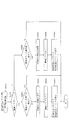
次に、図17を参照して、本パチンコ機10の電気的構成について説明する。図17は、パチンコ機10の電気的構成を示すブロック図である。
<Electrical Configuration in First Embodiment>
Next, the electrical configuration of the pachinko machine 10 will be described with reference to FIG. FIG. 17 is a block diagram showing an electrical configuration of the pachinko machine 10.

主制御装置110には、演算装置である1チップマイコンとしてのMPU201が搭載されている。MPU201には、該MPU201により実行される各種の制御プログラムや固定値データを記憶したROM202と、そのROM202内に記憶される制御プログラムの実行に際して各種のデータ等を一時的に記憶するためのメモリであるRAM203と、そのほか、割込回路やタイマ回路、データ送受信回路などの各種回路が内蔵されている。主制御装置110では、MPU201によって、大当たり抽選や第1図柄表示装置37、および第3図柄表示装置81における表示の設定、第2図柄表示装置における表示結果の抽選といったパチンコ機10の主要な処理を実行する。   The main controller 110 is equipped with an MPU 201 as a one-chip microcomputer that is an arithmetic unit. The MPU 201 includes a ROM 202 that stores various control programs executed by the MPU 201 and fixed value data, and a memory that temporarily stores various data when the control program stored in the ROM 202 is executed. A certain RAM 203 and various other circuits such as an interrupt circuit, a timer circuit, and a data transmission / reception circuit are incorporated. In the main controller 110, the MPU 201 performs main processing of the pachinko machine 10 such as jackpot lottery, display setting on the first symbol display device 37 and third symbol display device 81, and lottery of display results on the second symbol display device. Run.

なお、払出制御装置111や音声ランプ制御装置113などのサブ制御装置に対して動作を指示するために、主制御装置110から該サブ制御装置へ各種のコマンドがデータ送受信回路によって送信されるが、かかるコマンドは、主制御装置110からサブ制御装置へ一方向にのみ送信される。   Various commands are transmitted from the main control device 110 to the sub control device by the data transmission / reception circuit in order to instruct the sub control device such as the payout control device 111 and the sound lamp control device 113 to operate. Such a command is transmitted from the main controller 110 to the sub controller only in one direction.

まず、ROM202の内容について、図18を参照して説明する。図18(a)に示すように、主制御装置110のROM202には、上記した固定値データの一部として、第1当たり乱数テーブル202a、第1当たり種別選択テーブル202b、第2当たり乱数テーブル202c、および変動パターン選択テーブル202dが少なくとも記憶されている。   First, the contents of the ROM 202 will be described with reference to FIG. As shown in FIG. 18A, the ROM 202 of the main controller 110 stores, as part of the fixed value data, a first per-random number table 202a, a first per-type selection table 202b, and a second per-random number table 202c. , And a variation pattern selection table 202d are stored.

第1当たり乱数テーブル202a(図示せず)は、後述する第1当たり乱数カウンタC1の大当たり判定値が記憶されているデータテーブルである。詳細については、第1当たり乱数カウンタC1の説明と共に後述するが、始動入賞に基づいて取得した第1当たり乱数カウンタC1の値が、第1当たり乱数テーブル202aに規定されているいずれかの判定値と一致した場合に、特別図柄の大当たりであると判別される。   The first hit random number table 202a (not shown) is a data table in which a jackpot determination value of a first hit random number counter C1 described later is stored. The details will be described later together with the description of the first per-random number counter C1, but the value of the first per-random number counter C1 acquired based on the start winning is one of the determination values defined in the first per-random number table 202a. Is determined to be a special symbol jackpot.

第1当たり種別選択テーブル202b(図18(b)参照)は、大当たり種別を決定するための判定値が記憶されているデータテーブルであり、第1当たり種別カウンタC2の判定値が、各大当たり種別、および特別図柄の抽選契機となった入球口の種別に対応付けて規定されている。本実施形態のパチンコ機10では特別図柄の大当たりと判定された場合に、始動入賞に基づいて取得した第1当たり種別カウンタC2の値と、第1当たり種別選択テーブル202bとが比較され、第1当たり種別カウンタC2の値に対応する大当たり種別が選択される。   The first hit type selection table 202b (see FIG. 18B) is a data table in which a determination value for determining the big hit type is stored, and the determination value of the first hit type counter C2 is set to each big hit type. , And the type of entrance that triggered the lottery of special symbols. In the pachinko machine 10 of this embodiment, when it is determined that the special symbol is a big hit, the value of the first hit type counter C2 acquired based on the start winning is compared with the first hit type selection table 202b, and the first hit type selection table 202b is compared. A jackpot type corresponding to the value of the hit type counter C2 is selected.

具体的には、特別図柄1の抽選(第1入球口64への入球に基づく抽選)で大当たりとなった場合には、第1当たり種別カウンタC2の値が「0〜49」の範囲には、大当たりAが対応付けられて規定されている(図18(b)の202b1参照)。上述した通り、大当たりAとなった場合は、12ラウンド目において第2特定入賞口(第2大開放口)650aが開放される期間の大半が、流路切替弁650dの右側に設けられた誘導流路653が開放されている期間となるように構成されている(図16(a)参照)。よって、流路切替弁650dの左側に設けられた誘導流路652へと球を流下させることが困難となるので、誘導流路652の下流に設けられている確変入球口654へと球を入球させにくくなる。即ち、大当たりAとなった場合は、その大当たりの終了後に特別図柄の確変状態に移行しにくくなる。   Specifically, when the special symbol 1 lottery (the lottery based on the entrance to the first entrance 64) is a big win, the value of the first hit type counter C2 is in the range of “0 to 49”. Is defined in association with jackpot A (see 202b1 in FIG. 18B). As described above, when the jackpot is A, most of the period during which the second specific prize opening (second large opening) 650a is opened in the twelfth round is provided on the right side of the flow path switching valve 650d. The flow path 653 is configured to be open (see FIG. 16A). Therefore, it is difficult to make the sphere flow down to the guide channel 652 provided on the left side of the channel switching valve 650d. It becomes difficult to enter. That is, when the jackpot A is reached, it is difficult to shift to a special symbol probability changing state after the jackpot.

また、第1当たり種別カウンタC2の値が「50〜99」の範囲には、大当たりBが対応付けられて規定されている(図18(b)の202b2参照)。上述した通り、大当たりBとなった場合は、12ラウンド目において第2特定入賞口(第2大開放口)650aが開放される期間の全てが、流路切替弁650dの左側に設けられた誘導流路652が開放されている期間と重なるように構成されている(図16(b)参照)。よって、第2特定入賞口(第2大開放口)650aが開放されている間に球を第2特定入賞口(第2大開放口)650aへと入球させるだけで、流路切替弁650dの左側に設けられた誘導流路652へと球を流下させることができる。そして、上述した通り、誘導流路652の下流には、確変入球口654が設けられている。よって、大当たりBとなった場合は、その大当たりの終了後に特別図柄の確変状態に移行しやすくなる。   Further, a jackpot B is defined in association with the range of the value of the first hit type counter C2 “50 to 99” (see 202b2 in FIG. 18B). As described above, when the jackpot B is reached, the entire period during which the second specific winning opening (second large opening) 650a is opened in the 12th round is the guidance provided on the left side of the flow path switching valve 650d. The flow path 652 is configured to overlap with the open period (see FIG. 16B). Therefore, the flow path switching valve 650d can be obtained simply by allowing the ball to enter the second specific winning port (second large opening) 650a while the second specific winning port (second large opening) 650a is open. The sphere can be caused to flow down to a guide channel 652 provided on the left side. As described above, the probability variation inlet 654 is provided downstream of the guide channel 652. Therefore, when the jackpot B is reached, it becomes easy to shift to the probability change state of the special symbol after the jackpot ends.

一方、特別図柄2の抽選(第2入球口640への入球に基づく抽選)で大当たりとなった場合には、第1当たり種別カウンタC2の値が「0〜19」の範囲には、大当たりAが対応付けられて規定されている(図18(b)の202b3参照)。また、第1当たり種別カウンタC2の値が「20〜99」の範囲には、大当たりBが対応付けられて規定されている。即ち、特別図柄1の抽選により大当たりとなった場合に比較して、特別図柄2の抽選により大当たりとなった場合に、大当たりBとなる判定値の個数が多くなっている。よって、特別図柄2の抽選により大当たりとなった場合の方が大当たりBとなりやすく構成されている。   On the other hand, if the special symbol 2 lottery (lottery based on the entrance to the second entrance 640) is a big hit, the value of the first hit type counter C2 is in the range of “0-19” The jackpot A is defined in association with it (see 202b3 in FIG. 18B). Further, in the range where the value of the first hit type counter C2 is “20 to 99”, the big hit B is associated and defined. That is, the number of determination values for the big hit B is larger when the big win is won by the special symbol 2 lottery than when the special symbol 1 is the big hit. Therefore, it is easy to become the big hit B when it is a big hit by lottery of the special symbol 2.

上述した通り、特別図柄の確変中は、普通図柄の当たり確率がアップし、普通図柄の変動時間が短くなり(3秒)、普通図柄の当たりとなった場合における電動役物640aの開放時間が長くなる(1秒×2回)ように設定される。よって、第2入球口640へと球を入球させやすくなるので、特別図柄2の抽選が行われやすくなる。従って、一旦特別図柄の確変状態へと移行させることができれば、特別図柄の大当たりとなりやすく、且つ、大当たりとなった場合に大当たりBとなりやすい特別図柄の確変状態と、大当たりの終了後に特別図柄の確変状態となりやすい大当たりBとが繰り返されやすくなるので、遊技者が多量の賞球を獲得し易くなる。これにより、遊技者に対して特別図柄の確変状態へと移行させることを強く期待させながら遊技を行わせることができるので、遊技者の遊技に対する興趣を向上させることができる。   As described above, during the probability change of the special symbol, the probability of hitting the normal symbol is increased, the fluctuation time of the normal symbol is shortened (3 seconds), and the opening time of the electric accessory 640a when hitting the normal symbol is reached. It is set to be long (1 second × 2 times). Therefore, since it becomes easy to make a ball enter the 2nd entrance 640, it becomes easy to draw the special symbol 2 lottery. Therefore, once the special symbol can be shifted to the probable change state, the special symbol is likely to be a big hit, and if it is a big win, the special symbol is likely to become a big hit B. Since the big hit B, which tends to be in a state, is easily repeated, it is easy for the player to acquire a large number of prize balls. Thus, the game can be performed while strongly expecting the player to shift to the probabilistic state of the special symbol, so that the player's interest in the game can be improved.

第2当たり乱数テーブル202c(図18(c)参照)は、普通図柄の当たり判定値が記憶されているデータテーブルである。具体的には、普通図柄の通常状態において、普通図柄の当たりとなる判定値として、「5〜28」が規定されている(図18(c)の202c1参照)。また、普通図柄の高確率状態において、普通図柄の当たりとなる判定値として、「5〜204」が規定されている(図18(c)の202c2参照)。本実施形態のパチンコ機10では、普通入球口67を球が通過することに基づいて取得される第2当たり乱数カウンタC4の値と、第2当たり乱数テーブル202cとを参照し、普通図柄の当たりであるか否かを判定している。   The second hit random number table 202c (see FIG. 18C) is a data table in which the hit determination value for the normal symbol is stored. Specifically, “5 to 28” is defined as a determination value that is a hit of the normal symbol in the normal state of the normal symbol (see 202c1 in FIG. 18C). Further, “5 to 204” is defined as a determination value that is a hit of the normal symbol in the high probability state of the normal symbol (see 202c2 in FIG. 18C). In the pachinko machine 10 of the present embodiment, the value of the second per random number counter C4 acquired based on the passing of the ball through the normal entrance 67 and the second per random number table 202c are referred to, and the normal symbol It is determined whether or not it is a win.

変動パターン選択テーブル202d(図示なし)は、変動パターンの表示態様を決定するための変動種別カウンタCS1の判定値が表示態様毎にそれぞれ規定されているデータテーブルである。なお、変動パターン選択テーブル202dの詳細については、変動種別カウンタCS1の説明と共に後述する。   The variation pattern selection table 202d (not shown) is a data table in which the determination value of the variation type counter CS1 for determining the variation pattern display mode is defined for each display mode. The details of the variation pattern selection table 202d will be described later together with the description of the variation type counter CS1.

図17に戻って説明を続ける。主制御装置110では、特別図柄の抽選、普通図柄の抽選、第1図柄表示装置37における表示の設定、第2図柄表示装置83における表示の設定、および、第3図柄表示装置81における表示の設定といったパチンコ機10の主要な処理を実行する。そして、RAM203には、これらの処理を制御するための各種カウンタが設けられている。ここで、図19を参照して、主制御装置110のRAM203内に設けられるカウンタ等について説明する。これらのカウンタ等は、特別図柄の抽選、普通図柄の抽選、第1図柄表示装置37における表示の設定、第2図柄表示装置83における表示の設定、および、第3図柄表示装置81における表示の設定などを行うために、主制御装置110のMPU201で使用される。   Returning to FIG. 17, the description will be continued. In main controller 110, special symbol lottery, normal symbol lottery, display setting on first symbol display device 37, display setting on second symbol display device 83, and display setting on third symbol display device 81 The main processing of the pachinko machine 10 is executed. The RAM 203 is provided with various counters for controlling these processes. Here, with reference to FIG. 19, a counter and the like provided in the RAM 203 of the main controller 110 will be described. These counters, etc., are a special symbol lottery, a normal symbol lottery, a display setting on the first symbol display device 37, a display setting on the second symbol display device 83, and a display setting on the third symbol display device 81. For example, the MPU 201 of the main control device 110 is used.

特別図柄の抽選や、第1図柄表示装置37および第3図柄表示装置81の表示の設定には、特別図柄の抽選に使用する第1当たり乱数カウンタC1と、特別図柄の大当たり種別を選択するために使用する第1当たり種別カウンタC2と、特別図柄における外れの停止種別を選択するために使用する停止種別選択カウンタC3と、第1当たり乱数カウンタC1の初期値設定に使用する第1初期値乱数カウンタCINI1と、変動パターン選択に使用する変動種別カウンタCS1とが用いられる。また、普通図柄の抽選には、第2当たり乱数カウンタC4が用いられ、第2当たり乱数カウンタC4の初期値設定には第2初期値乱数カウンタCINI2が用いられる。これら各カウンタは、更新の都度、前回値に1が加算され、最大値に達した後0に戻るループカウンタとなっている。   In order to select a special symbol lottery and the first symbol random number counter C1 used for the special symbol lottery and the special symbol lottery for setting the display of the first symbol display device 37 and the third symbol display device 81 The first per-type counter C2 used for the selection, the stop-type selection counter C3 used for selecting the out-of-service stop type in the special symbol, and the first initial value random number used for setting the initial value of the first per-random number counter C1 A counter CINI1 and a variation type counter CS1 used for variation pattern selection are used. In addition, the second random number counter C4 is used for lottery of normal symbols, and the second initial random number counter CINI2 is used for setting the initial value of the second random number counter C4. Each of these counters is a loop counter that adds 1 to the previous value every time it is updated and returns to 0 after reaching the maximum value.

各カウンタは、例えば、タイマ割込処理(図25参照)の実行間隔である2ミリ秒間隔で更新され、また、一部のカウンタは、メイン処理(図34参照)の中で不定期に更新されて、その更新値がRAM203の所定領域に設定されたカウンタ用バッファに適宜格納される。RAM203には、1つの実行エリアと4つの保留エリア(保留第1〜第4エリア)とからなる第1入球口64への入賞に対応する特別図柄1保留球格納エリア203aと第2入球口640への入賞に対応する特別図柄2保留球格納エリア203bとがそれぞれ設けられており、これらの各エリアには、第1入球口64または第2入球口640への入球タイミングに合わせて、第1当たり乱数カウンタC1、第1当たり種別カウンタC2及び停止種別選択カウンタC3の各値がそれぞれ格納される。また、RAM203には、1つの実行エリアと4つの保留エリア(保留第1〜第4エリア)とからなる普通図柄保留球格納エリア203cが設けられており、これらの各エリアには、球が普通入球口(スルーゲート)67を通過したタイミングに合わせて、第2当たり乱数カウンタC4の値が格納される。   Each counter is updated, for example, at an interval of 2 milliseconds, which is an execution interval of the timer interrupt process (see FIG. 25), and some counters are updated irregularly in the main process (see FIG. 34). Then, the updated value is appropriately stored in a counter buffer set in a predetermined area of the RAM 203. In the RAM 203, a special symbol 1 reserved ball storage area 203a corresponding to winning in the first entrance 64 comprising one execution area and four reservation areas (holding first to fourth areas) and a second entry A special symbol 2 reserved ball storage area 203b corresponding to winning in the mouth 640 is provided, and in each of these areas, the timing of entering the first entrance 64 or the second entrance 640 is provided. In addition, each value of the first per-random number counter C1, the first per-type counter C2, and the stop type selection counter C3 is stored. The RAM 203 is provided with a normal symbol holding ball storage area 203c including one execution area and four holding areas (holding first to fourth areas). In each of these areas, a sphere is normally used. The value of the second per-random number counter C4 is stored in accordance with the timing of passing through the entrance (through gate) 67.

図19を参照して、各カウンタについて詳しく説明する。第1当たり乱数カウンタC1は、所定の範囲(例えば、0〜399)内で順に1ずつ加算され、最大値(例えば、0〜399の値を取り得るカウンタの場合は399)に達した後0に戻る構成となっている。特に、第1当たり乱数カウンタC1が1周した場合、その時点の第1初期値乱数カウンタCINI1の値が当該第1当たり乱数カウンタC1の初期値として読み込まれる。   Each counter will be described in detail with reference to FIG. The first random number counter C1 is incremented one by one within a predetermined range (for example, 0 to 399) and reaches 0 after reaching the maximum value (for example, 399 in the case of a counter that can take a value of 0 to 399). It is the composition which returns to. In particular, when the first random number counter C1 makes one round, the value of the first initial value random number counter CINI1 at that time is read as the initial value of the first random number counter C1.

また、第1初期値乱数カウンタCINI1は、第1当たり乱数カウンタC1と同一範囲で更新されるループカウンタとして構成される。即ち、例えば、第1当たり乱数カウンタC1が0〜399の値を取り得るループカウンタである場合には、第1初期値乱数カウンタCINI1もまた、0〜399の範囲のループカウンタである。この第1初期値乱数カウンタCINI1は、タイマ割込処理(図25参照)の実行毎に1回更新されると共に、メイン処理(図34参照)の残余時間内で繰り返し更新される。   The first initial value random number counter CINI1 is configured as a loop counter that is updated in the same range as the first random number counter C1. That is, for example, when the first random number counter C1 is a loop counter that can take a value of 0 to 399, the first initial value random number counter CINI1 is also a loop counter in the range of 0 to 399. The first initial value random number counter CINI1 is updated once every execution of the timer interrupt process (see FIG. 25), and is repeatedly updated within the remaining time of the main process (see FIG. 34).

第1当たり乱数カウンタC1の値は、例えば定期的に(本実施形態ではタイマ割込処理毎に1回)更新され、球が第1入球口64または第2入球口640に入賞したタイミングでRAM203の特別図柄1保留球格納エリア203aまたは特別図柄2保留球格納エリア203bに格納される。そして、特別図柄の大当たりとなる乱数の値は、主制御装置110のROM202に格納される第1当たり乱数テーブル202a(図示せず)によって設定されており、第1当たり乱数カウンタC1の値が、第1当たり乱数テーブル202aによって設定された大当たりとなる乱数の値と一致する場合に、特別図柄の大当たりと判定する。また、この第1当たり乱数テーブル202aは、特別図柄の低確率時(特別図柄の低確率状態である期間)用と、その低確率時より特別図柄の大当たりとなる確率の高い高確率時(特別図柄の高確率状態である期間)用との2種類に分けられ、それぞれに含まれる大当たりとなる乱数の個数が異なって設定されている。このように、大当たりとなる乱数の個数を異ならせることにより、特別図柄の低確率時と特別図柄の高確率時とで、大当たりとなる確率が変更される。   The value of the first random number counter C1 is updated, for example, periodically (in this embodiment, once for each timer interrupt process), and the timing at which the ball wins the first entrance 64 or the second entrance 640 Are stored in the special symbol 1 reserved ball storage area 203a or the special symbol 2 reserved ball storage area 203b of the RAM 203. The random number value that is a big hit of the special symbol is set by a first random number table 202a (not shown) stored in the ROM 202 of the main controller 110, and the value of the first random number counter C1 is When the value of the random number that is a big hit set by the first hit random number table 202a matches, it is determined that the special symbol is a big hit. The first random number table 202a is used for a low probability of a special symbol (a period in which the special symbol is in a low probability state) and a high probability of a special symbol having a high probability of being a big hit than the low probability (special). The period is a high probability state of symbols) and the number of random numbers that are jackpots included in each is set differently. In this way, by changing the number of random numbers that are jackpots, the probability of jackpots is changed between when the special symbol has a low probability and when the special symbol has a high probability.

ここで、第1当たり乱数テーブル202aについて説明する。第1当たり乱数テーブル202aは、第1特別図柄または第2特別図柄の抽選において、各遊技状態で当たりと判定される乱数値(判定値)が設定されたテーブルである。具体的には、特別図柄の確変状態である場合には、第1特別図柄または第2特別図柄の抽選において、取得した第1当たり乱数カウンタC1の値が「0〜9」のいずれであるか判別されて、「0〜9」のいずれかであれば、大当たりであると判別される。第1当たり乱数カウンタC1の取り得る値が「0〜399」の400個ある中で、大当たりとなる判定値が「0〜9」の10個なので、特別図柄の確変中に特別図柄の大当たりとなる確率は、1/40(10/400)となる。また、特別図柄の低確率状態である場合には、取得した第1当たり乱数カウンタC1の値が「200」であるか判別されて、「200」であれば大当たりであると判別される。第1当たり乱数カウンタC1の取り得る値が「0〜399」の400個ある中で、大当たりとなる判定値が「200」の1個のみなので、特別図柄の低確率状態おいてに特別図柄の大当たりとなる確率は、1/400となる。   Here, the first random number table 202a will be described. The first winning random number table 202a is a table in which random numbers (determination values) determined to be winning in each gaming state in the lottery of the first special symbol or the second special symbol are set. Specifically, if the special symbol is in a probable variation state, whether the value of the first random number counter C1 acquired is “0-9” in the lottery of the first special symbol or the second special symbol. If it is determined and any one of “0-9”, it is determined that it is a big hit. Among the 400 possible values of the first random number counter C1 “0 to 399”, the judgment value that is a big hit is 10 “0 to 9”. Probability becomes 1/40 (10/400). If the special symbol is in a low probability state, it is determined whether the value of the acquired first random number counter C1 is “200”, and if it is “200”, it is determined that it is a big hit. Among the 400 possible values of the first random number counter C1 “0 to 399”, the judgment value that is a big hit is only one of “200”, so that the special symbol has a low probability state. The probability of winning a jackpot is 1/400.

なお、本実施形態では、低確率時用の第1当たり乱数テーブルに格納されている大当たりとなる乱数値と、高確率時用の第1当たり乱数テーブルに格納されている大当たりとなる乱数値とで、重複した値とならないように、それぞれの大当たりとなる乱数値を設定している。ここで、大当たりとなる乱数値としてパチンコ機10の状況にかかわらず常に用いられる値が存在すれば、その乱数値が外部より入力されて、不正に大当たりを引き当てられやすくなるおそれがある。これに対して、本実施形態のように、状況に応じて(即ち、パチンコ機10が特別図柄の高確率状態か、特別図柄の低確率状態かに応じて)、大当たりとなる乱数値を変えることで、特別図柄の大当たりとなる乱数値が予測され難くすることができるので、不正に対する抑制を図ることができる。   In the present embodiment, the random number value that is a jackpot stored in the first per-random number table for the low probability time, and the random number value that is the jackpot stored in the first per-random number table for the high probability time In order to avoid duplicate values, random numbers for each jackpot are set. Here, if there is a value that is always used as a jackpot random value regardless of the situation of the pachinko machine 10, the random value may be input from the outside, and the jackpot may be easily illegally assigned. On the other hand, as in this embodiment, depending on the situation (that is, depending on whether the pachinko machine 10 is in a high probability state of a special symbol or a low probability state of a special symbol), the random number value that is a jackpot is changed. As a result, it is possible to make it difficult to predict a random value that is a big hit of a special symbol, and thus it is possible to suppress fraud.

第1当たり種別カウンタC2は、特別図柄の大当たりとなった場合に、第1図柄表示装置37の表示態様を決定するものであり、所定の範囲(例えば、0〜99)内で順に1ずつ加算され、最大値(例えば、0〜99の値を取り得るカウンタの場合は99)に達した後0に戻る構成となっている。第1当たり種別カウンタC2の値は、例えば、定期的に(本実施形態ではタイマ割込処理毎に1回)更新され、球が第1入球口64に入賞したタイミングでRAM203の特別図柄1保留球格納エリア203aに格納される。   The first hit type counter C2 determines the display mode of the first symbol display device 37 when the special symbol is a big hit, and increments one by one within a predetermined range (for example, 0 to 99). Then, after reaching the maximum value (for example, 99 in the case of a counter that can take a value of 0 to 99), it returns to 0. The value of the first hit type counter C2 is updated, for example, periodically (once every timer interrupt process in the present embodiment), and the special symbol 1 of the RAM 203 at the timing when the ball wins the first entrance 64. It is stored in the reserved ball storage area 203a.

ここで、特別図柄1保留球格納エリア203aまたは特別図柄2保留球格納エリア203bに格納された第1当たり乱数カウンタC1の値が、特別図柄の大当たりとなる乱数でなければ、即ち、特別図柄の外れとなる乱数であれば、第1図柄表示装置37に表示される停止図柄に対応した表示態様は、特別図柄の外れ時のものとなる。   Here, if the value of the first per random number counter C1 stored in the special symbol 1 reserved ball storage area 203a or the special symbol 2 reserved ball storage area 203b is not a random number that is a big hit of the special symbol, If the random number is off, the display mode corresponding to the stop symbol displayed on the first symbol display device 37 is that when the special symbol is off.

一方で、特別図柄1保留球格納エリア203aまたは特別図柄2保留球格納エリア203bに格納された第1当たり乱数カウンタC1の値が、特別図柄の大当たりとなる乱数であれば、第1図柄表示装置37に表示される停止図柄に対応した表示態様は、特別図柄の大当たり時のものとなる。この場合、その大当たり時の具体的な表示態様は、同じ特別図柄1保留球格納エリア203aに格納されている第1当たり種別カウンタC2の値が示す表示態様となる。   On the other hand, if the value of the first random number counter C1 stored in the special symbol 1 reserved ball storage area 203a or the special symbol 2 reserved ball storage area 203b is a random number that is a big hit of the special symbol, the first symbol display device The display mode corresponding to the stop symbol displayed in 37 is that of the special symbol jackpot. In this case, the specific display mode at the time of the big hit is the display mode indicated by the value of the first hit type counter C2 stored in the same special symbol 1 reserved ball storage area 203a.

また、本実施形態のパチンコ機10における第1当たり種別カウンタC2の値は、0〜99の範囲のループカウンタとして構成されている。そして、特別図柄1の抽選により大当たりとなり、第1当たり種別カウンタC2において、乱数値が「0〜49」のいずれかであった場合の大当たり種別は、「大当たりA」となる。また、特別図柄1の抽選により大当たりとなり、乱数値が「50〜99」のいずれかであった場合の大当たり種別は、「大当たりB」となる。更に、特別図柄2の抽選により大当たりとなり、第1当たり種別カウンタC2において、乱数値が「0〜19」のいずれかであった場合の大当たり種別は、「大当たりA」となる。また、特別図柄2の抽選により大当たりとなり、乱数値が「20〜99」のいずれかであった場合の大当たり種別は、「大当たりB」となる。   Further, the value of the first hit type counter C2 in the pachinko machine 10 of the present embodiment is configured as a loop counter in the range of 0-99. And if the random number is any one of “0 to 49” in the first hit type counter C2, the big hit type is “hit A”. In addition, when the special symbol 1 is drawn by lottery, the jackpot type when the random number value is any of “50 to 99” is “jackpot B”. Furthermore, the big hit type when the special symbol 2 is lottery and the random number value is any one of “0 to 19” in the first hit type counter C2 is “big hit A”. In addition, the jackpot type when the special symbol 2 is drawn by lottery and the random value is any one of “20 to 99” is “jackpot B”.

なお、本実施形態では、大当たりの種類は2種類としたが、それに限らず、1種類でもよいし、2種類以上設けるように構成してもよい。また、特別図柄1の抽選により大当たりとなった場合と、特別図柄2の抽選により大当たりとなった場合とで、同じ第1当たり種別カウンタC2の値では、同じ大当たり種別が選択されるように構成してもよい。このように構成することで、第1当たり種別選択テーブル202bのデータ量を削減することができるので、ROM202の容量を削減することができる。   In the present embodiment, the number of jackpots is two. However, the present invention is not limited to this. One type may be used, or two or more types may be provided. Further, the same jackpot type is selected with the same value of the first hit type counter C2 between the case where the special symbol 1 is a lottery and the case where the special symbol 2 is a lottery. May be. With this configuration, the amount of data in the first hit type selection table 202b can be reduced, so that the capacity of the ROM 202 can be reduced.

変動種別カウンタCS1は、例えば0〜198の範囲内で順に1ずつ加算され、最大値(つまり198)に達した後0に戻る構成となっている。変動種別カウンタCS1によって、いわゆる短時間はずれ、長時間はずれ、ノーマルリーチ、スーパーリーチ等の大まかな表示態様が決定される。表示態様の決定は、具体的には、図柄変動の変動時間の決定である。変動種別カウンタCS1により決定された変動時間に基づいて、音声ランプ制御装置113や表示制御装置114により第3図柄表示装置81で表示される第3図柄のリーチ種別や細かな図柄変動態様が決定される。変動種別カウンタCS1の値は、後述するメイン処理(図34参照)が1回実行される毎に1回更新され、当該メイン処理内の残余時間内でも繰り返し更新される。尚、変動種別カウンタCS1の値(乱数値)から、図柄変動の変動時間を一つ決定する乱数値を格納した変動パターン選択テーブル202dは、上述した通り、主制御装置110のROM202内に設けられている。   The variation type counter CS1 is, for example, incremented by 1 within a range of 0 to 198, and returns to 0 after reaching the maximum value (that is, 198). A rough display mode such as so-called short-time deviation, long-term deviation, normal reach, and super reach is determined by the variation type counter CS1. Specifically, the display mode is determined by determining the variation time of the symbol variation. Based on the fluctuation time determined by the fluctuation type counter CS1, the voice lamp control device 113 and the display control device 114 determine the reach type of the third symbol displayed on the third symbol display device 81 and the detailed symbol variation mode. The The value of the variation type counter CS1 is updated once every time a main process (see FIG. 34) described later is executed once, and is repeatedly updated even within the remaining time in the main process. Note that the variation pattern selection table 202d that stores a random value for determining one variation time of symbol variation from the value of the variation type counter CS1 (random number value) is provided in the ROM 202 of the main controller 110 as described above. ing.

変動パターン選択テーブル202dには、例えば、外れ用の変動パターンとして、「外れ(長時間用)」、「外れ(短時間用)」、「外れノーマルリーチ」各種、「外れスーパーリーチ」各種が規定され、大当たり用の変動パターンとして、「ノーマルリーチ」各種、「スーパーリーチ」各種が規定されている。そして、変動パターンテーブルに規定された各種変動パターンから、予測された抽選結果や、予測された停止種別(大当たりの場合には大当たり種別)に応じて変動パターンが選定される。   In the variation pattern selection table 202d, for example, “out (for long time)”, “out (for short time)”, “out normal reach”, and “out super reach” are defined as variation patterns for out. As a variation pattern for jackpot, “normal reach” and “super reach” are defined. Then, a variation pattern is selected from the various variation patterns defined in the variation pattern table according to the predicted lottery result and the predicted stop type (a jackpot type in the case of a jackpot).

第2当たり乱数カウンタC4は、例えば0〜239の範囲内で順に1ずつ加算され、最大値(つまり239)に達した後0に戻るループカウンタとして構成されている。また、第2当たり乱数カウンタC4が1周した場合、その時点の第2初期値乱数カウンタCINI2の値が当該第2当たり乱数カウンタC4の初期値として読み込まれる。第2当たり乱数カウンタC4の値は、本実施形態ではタイマ割込処理毎に、例えば定期的に更新され、球が普通入球口(スルーゲート)67を通過したことが検知された時に取得され、RAM203の普通図柄保留球格納エリア203cに格納される。   The second random number counter C4 is configured as a loop counter that is incremented one by one within a range of, for example, 0 to 239 and returns to 0 after reaching the maximum value (that is, 239). Further, when the second random number counter C4 makes one round, the value of the second initial value random number counter CINI2 at that time is read as the initial value of the second random number counter C4. In the present embodiment, the value of the second random number counter C4 is updated periodically, for example, every timer interrupt process, and is acquired when it is detected that the ball has passed through the normal entrance (through gate) 67. , Stored in the normal symbol holding ball storage area 203c of the RAM 203.

そして、普通図柄の当たりとなる乱数の値は、主制御装置のROM202に格納される第2当たり乱数テーブル202c(図18(c)参照)によって設定されており、第2当たり乱数カウンタC4の値が、第2当たり乱数テーブル202cによって設定された当たりとなる乱数の値と一致する場合に、普通図柄の当たりと判定する。また、この第2当たり乱数テーブル202cは、普通図柄の低確率時(普通図柄の通常状態である期間)用(図18(c)の202c1参照)と、その低確率時より普通図柄の当たりとなる確率の高い高確率時(普通図柄の時短状態である期間、および特別図柄の確変状態である期間)用(図18(c)の202c2参照)との2種類に分けられ、それぞれに含まれる大当たりとなる乱数の個数が異なって設定されている。このように、当たりとなる乱数の個数を異ならせることにより、普通図柄の低確率時(普通図柄の通常状態)と普通図柄の高確率時(普通図柄の時短状態)とで、当たりとなる確率が変更される。   The value of the random number that is a normal symbol is set by the second random number table 202c (see FIG. 18C) stored in the ROM 202 of the main controller, and the value of the second random number counter C4. Is determined to be a normal symbol hit when it matches the value of the random number set in the second hit random number table 202c. In addition, the second random number table 202c is used for a normal symbol at a low probability (a period in which the normal symbol is in a normal state) (see 202c1 in FIG. 18C), and a normal symbol hit from the low probability. It is divided into two types for high probability (period of normal symbol time-short state and period of special symbol probability variation state) (see 202c2 in FIG. 18 (c)) and included in each. The number of random numbers that are jackpots is set differently. In this way, by varying the number of winning random numbers, the probability of winning when the normal symbol has a low probability (normal state of normal symbol) and when the normal symbol has a high probability (normal symbol time short state) Is changed.

図18(c)に示すように、普通図柄の低確率時に、普通図柄の当たりとなる乱数値は24個あり、その範囲は「5〜28」となっている(図18(c)の202c1参照)。このように普通図柄の低確率時には、乱数値の総数が240ある中で、大当たりとなる乱数値の総数が24なので、特別図柄の大当たりとなる確率は、「1/10」となる。   As shown in FIG. 18 (c), there are 24 random numbers that are hit by the normal symbol when the normal symbol has a low probability, and the range is “5-28” (202c1 in FIG. 18 (c)). reference). Thus, when the probability of a normal symbol is low, the total number of random numbers that are jackpots is 24 among the total number of random number values, and therefore the probability of jacking a special symbol is “1/10”.

パチンコ機10が普通図柄の低確率時である場合に、球が普通入球口67を通過すると、第2当たり乱数カウンタC4の値が取得されると共に、第2図柄表示装置83において普通図柄の変動表示が30秒間実行される。そして、取得された第2当たり乱数カウンタC4の値が「5〜28」の範囲であれば当選と判定されて、第2図柄表示装置83における変動表示が終了した後に、停止図柄(第2図柄)として「○」の図柄が点灯表示されると共に、第2入球口640に付随する電動役物640aが「0.2秒間×1回」だけ開放される。尚、本実施形態では、パチンコ機10が普通図柄の低確率時である場合に、普通図柄の当たりとなったら電動役物640aが「0.2秒間×1回」だけ開放されるが、開放時間や回数は任意に設定すれば良い。例えば、「0.5秒間×2回」開放しても良い。   When the pachinko machine 10 has a low probability of a normal symbol, when the ball passes through the normal entrance 67, the value of the second random number counter C4 is acquired, and the second symbol display device 83 displays the normal symbol. The variable display is executed for 30 seconds. Then, if the value of the acquired second random number counter C4 is in the range of “5 to 28”, it is determined that the winning symbol is selected, and after the variable display on the second symbol display device 83 ends, the stop symbol (second symbol) ), The symbol “◯” is lit and displayed, and the electric accessory 640a associated with the second entrance 640 is opened “for 0.2 seconds × 1 time”. In the present embodiment, when the pachinko machine 10 has a low probability of a normal symbol, the electric accessory 640a is opened only "0.2 seconds x once" when the normal symbol is hit. What is necessary is just to set time and frequency | count arbitrarily. For example, “0.5 seconds × 2 times” may be opened.

一方で、普通図柄の高確率時(普通図柄の時短中、および特別図柄の確変中)に、普通図柄の大当たりとなる乱数値は200個あり、その範囲は「5〜204」となっている。これらの乱数値は、高確率時用の第2当たり乱数テーブル202cに格納されている(図18(c)の202c2参照)。このように特別図柄の低確率時には、乱数値の総数が240ある中で、大当たりとなる乱数値の総数が200なので、特別図柄の大当たりとなる確率は、「1/1.2」となる。   On the other hand, there are 200 random numbers that are big hits of normal symbols when the probability of normal symbols is high (when the normal symbols are short and short, and during special symbols), the range is “5-204”. . These random number values are stored in the second per random number table 202c for high probability (see 202c2 in FIG. 18C). Thus, when the special symbol has a low probability, the total number of random numbers that are jackpots is 200 among the total number of random number values, and therefore, the probability that the special symbol is jackpot is “1 / 1.2”.

パチンコ機10が普通図柄の高確率時である場合に、球が普通入球口67を通過すると、第2当たり乱数カウンタC4の値が取得されると共に、第2図柄表示装置83において普通図柄の変動表示が3秒間実行される。そして、取得された第2当たり乱数カウンタC4の値が「5〜204」の範囲であれば当選と判定されて、第2図柄表示装置83における変動表示が終了した後に、停止図柄(第2図柄)として「○」の図柄が点灯表示されると共に、第2入球口640に付随する電動役物640aが「1秒間×2回」開放される。このように、普通図柄の高確率時には、普通図柄の低確率時と比較して、変動表示の時間が「30秒→3秒」と非常に短くなり、更に、電動役物640aの開放期間が「0.2秒×1回→1秒間×2回」と非常に長くなるので、第2入球口640へ球が入球し易い状態となる。尚、本実施形態では、パチンコ機10が普通図柄の高確率時である場合に、普通図柄の当たりとなったら第2入球口640に付随する電動役物640aが「1秒間×2回」だけ開放されるが、開放時間や回数は任意に設定すれば良い。例えば、「3秒間×3回」開放しても良い。   When the pachinko machine 10 has a high probability of a normal symbol, when the ball passes the normal entrance 67, the value of the second random number counter C4 is acquired and the second symbol display device 83 displays the normal symbol. The variable display is executed for 3 seconds. Then, if the acquired value of the second random number counter C4 is in the range of “5 to 204”, it is determined that the winning symbol is selected, and after the variable display on the second symbol display device 83 ends, the stop symbol (second symbol) ), The symbol “◯” is lit and displayed, and the electric accessory 640a associated with the second entrance 640 is opened “twice × 1 second”. In this way, when the normal symbol has a high probability, the variation display time is very short, “30 seconds → 3 seconds”, compared to when the normal symbol has a low probability, and the opening period of the electric accessory 640a is further shortened. Since “0.2 seconds × 1 time → 1 second × 2 times” is very long, it becomes easy for the ball to enter the second entrance 640. In the present embodiment, when the pachinko machine 10 has a high probability of a normal symbol, the electric accessory 640a associated with the second entrance 640 is “one second × two times” when the normal symbol is hit. However, the opening time and number of times may be set arbitrarily. For example, “3 seconds × 3 times” may be opened.

第2初期値乱数カウンタCINI2は、第2当たり乱数カウンタC4と同一範囲で更新されるループカウンタとして構成され(値=0〜239)、タイマ割込処理(図25参照)毎に1回更新されると共に、メイン処理(図34参照)の残余時間内で繰り返し更新される。   The second initial value random number counter CINI2 is configured as a loop counter that is updated in the same range as the second random number counter C4 (value = 0 to 239), and is updated once every timer interrupt process (see FIG. 25). And repeatedly updated within the remaining time of the main process (see FIG. 34).

このように、RAM203には種々のカウンタ等が設けられており、主制御装置110では、このカウンタ等の値に応じて大当たり抽選や第1図柄表示装置37および第3図柄表示装置81における表示の設定、第2図柄表示装置83における表示結果の抽選といったパチンコ機10の主要な処理を実行することができる。   As described above, the RAM 203 is provided with various counters and the like, and the main control device 110 performs the big win lottery and the display in the first symbol display device 37 and the third symbol display device 81 according to the value of the counter and the like. The main processing of the pachinko machine 10 such as setting and lottery of the display result on the second symbol display device 83 can be executed.

図17に戻り、説明を続ける。RAM203は、図19に図示した各種カウンタのほか、MPU201の内部レジスタの内容やMPU201により実行される制御プログラムの戻り先番地などが記憶されるスタックエリアと、各種のフラグおよびカウンタ、I/O等の値が記憶される作業エリア(作業領域)とを有している。   Returning to FIG. 17, the description will be continued. In addition to the various counters shown in FIG. 19, the RAM 203 stores a stack area for storing the contents of the internal registers of the MPU 201 and the return address of a control program executed by the MPU 201, various flags and counters, I / O, and the like. There is a work area (work area) in which the value is stored.

なお、RAM203は、パチンコ機10の電源の遮断後においても電源装置115からバックアップ電圧が供給されてデータを保持(バックアップ)できる構成となっており、RAM203に記憶されるデータは、すべてバックアップされる。   Note that the RAM 203 is configured so that the backup voltage is supplied from the power supply device 115 and the data can be retained (backed up) even after the power of the pachinko machine 10 is shut off, and all data stored in the RAM 203 is backed up. .

停電などの発生により電源が遮断されると、その電源遮断時(停電発生時を含む。以下同様)のスタックポインタや、各レジスタの値がRAM203に記憶される。一方、電源投入時(停電解消による電源投入を含む。以下同様)には、RAM203に記憶される情報に基づいて、パチンコ機10の状態が電源遮断前の状態に復帰される。RAM203への書き込みはメイン処理(図34参照)によって電源遮断時に実行され、RAM203に書き込まれた各値の復帰は電源投入時の立ち上げ処理(図33参照)において実行される。なお、MPU201のNMI端子(ノンマスカブル割込端子)には、停電等の発生による電源遮断時に、停電監視回路252からの停電信号SG1が入力されるように構成されており、その停電信号SG1がMPU201へ入力されると、停電時処理としてのNMI割込処理(図32参照)が即座に実行される。   When the power is shut down due to the occurrence of a power failure or the like, the stack pointer and the value of each register when the power is shut off (including when the power failure occurs, the same applies hereinafter) are stored in the RAM 203. On the other hand, at the time of power-on (including power-on due to power failure cancellation, the same applies hereinafter), the state of the pachinko machine 10 is restored to the state before power-off based on information stored in the RAM 203. Writing to the RAM 203 is executed when the power is shut off by the main process (see FIG. 34), and restoration of each value written in the RAM 203 is executed in a startup process (see FIG. 33) when the power is turned on. Note that the power failure signal SG1 from the power failure monitoring circuit 252 is input to the NMI terminal (non-maskable interrupt terminal) of the MPU 201 when the power is interrupted due to the occurrence of a power failure or the like. Is input immediately, the NMI interrupt process (see FIG. 32) is immediately executed as a power failure process.

ここで、RAM203に記憶される各種のフラグおよびカウンタの詳細について、図20を参照して説明する。RAM203は、図20に示すように、特別図柄1保留球格納エリア203a、特別図柄2保留球格納エリア203b、普通図柄保留球格納エリア203c、特別図柄1保留球数カウンタ203d、特別図柄2保留球数カウンタ203e、普通図柄保留球数カウンタ203f、確変フラグ203g、確変設定フラグ203h、確変通過カウンタ203i、入賞個数カウンタ203j、動作カウンタ203k、残球タイマフラグ203m、残球タイマ203n、確変有効フラグ203o、確変有効タイマ203p、排出個数カウンタ203q、時短中カウンタ203r、その他メモリエリア203zを有している。   Here, details of various flags and counters stored in the RAM 203 will be described with reference to FIG. As shown in FIG. 20, the RAM 203 has a special symbol 1 reserved ball storage area 203a, a special symbol 2 reserved ball storage area 203b, a normal symbol reserved ball storage area 203c, a special symbol 1 reserved ball number counter 203d, and a special symbol 2 reserved ball. Number counter 203e, normal symbol holding ball number counter 203f, probability variation flag 203g, probability variation setting flag 203h, probability variation passing counter 203i, winning number counter 203j, operation counter 203k, remaining ball timer flag 203m, remaining ball timer 203n, probability variation valid flag 203o , A probability variation valid timer 203p, a discharge number counter 203q, an hour / medium counter 203r, and a memory area 203z.

特別図柄1保留球格納エリア203aは、1つの実行エリアと、4つの保留エリア(保留第1エリア〜保留第4エリア)とを有しており、これらの各エリアには、第1入球口64に入賞したことに基づいて取得された第1当たり乱数カウンタC1、第1当たり種別カウンタC2の各値がそれぞれ格納される。   The special symbol 1 holding ball storage area 203a has one execution area and four holding areas (holding first area to holding fourth area). Each of these areas has a first entrance Each value of the first per-random number counter C1 and the first per-type counter C2 acquired based on winning of 64 is stored.

より具体的には、球が第1入球口64へ入賞(始動入賞)したタイミングで、各カウンタC1〜C3の各値が取得され、その取得されたデータが、4つの保留エリア(保留第1エリア〜保留第4エリア)の空いているエリアの中で、エリア番号(第1〜第4)の小さいエリアから順番に記憶される。つまり、エリア番号の小さいエリアほど、時間的に古い入賞に対応するデータが記憶され、保留第1エリアには、時間的に最も古い入賞に対応するデータが記憶される。尚、4つの保留エリアの全てにデータが記憶されている場合には、新たに何も記憶されない。   More specifically, each value of each of the counters C1 to C3 is acquired at the timing when the ball wins the first entrance 64 (start winning), and the acquired data is stored in four holding areas (holding first). Among the vacant areas (1 area to reserved 4th area), the areas are stored in order from the area with the smallest area number (1st to 4th). That is, as the area number is smaller, the data corresponding to the winning that is older in time is stored, and the data corresponding to the winning that is older in time is stored in the first reserved area. If data is stored in all four reserved areas, nothing is newly stored.

その後、主制御装置110において、特別図柄の抽選が行われる場合には、特別図柄1保留球格納エリア203aの保留第1エリアに記憶されている各カウンタC1〜C3の各値が、実行エリアへシフトされ(移動させられ)、その実行エリアに記憶された各カウンタC1〜C3の各値に基づいて、特別図柄の抽選などの判定が行われる。   Thereafter, when the special controller lottery is performed in the main controller 110, the values of the counters C1 to C3 stored in the reserved first area of the special symbol 1 reserved ball storage area 203a are transferred to the execution area. Based on the values of the counters C1 to C3 that are shifted (moved) and stored in the execution area, a determination such as lottery of a special symbol is performed.

なお、保留第1エリアから実行エリアへデータをシフトすると、保留第1エリアが空き状態となる。そこで、他の保留エリア(保留第2エリア〜保留第4エリア)に記憶されている入賞のデータを、エリア番号の1小さい保留エリア(保留第1エリア〜保留第3エリア)に詰めるシフト処理が行われる。本実施形態では、特別図柄1保留球格納エリア203aにおいて、入賞のデータが記憶されている保留エリア(第2保留エリア〜第4保留エリア)についてのみデータのシフトが行われる。   Note that when data is shifted from the reserved first area to the execution area, the reserved first area becomes empty. Therefore, a shift process is performed in which winning data stored in other reserved areas (holding second area to holding fourth area) is packed into a holding area having a smaller area number (holding first area to holding third area). Done. In the present embodiment, in the special symbol 1 reserved ball storage area 203a, data is shifted only for the reserved areas (second reserved area to fourth reserved area) in which winning data is stored.

特別図柄2保留球格納エリア203bは、特別図柄1保留球格納エリア203aに対して、第2入球口640への入賞に対して取得されたカウンタ値がそれぞれ記憶される点で異なるのみであり、その他の構成については、同一であるので、詳細な説明については省略する。   The special symbol 2 reserved ball storage area 203b is different from the special symbol 1 reserved ball storage area 203a only in that counter values acquired for winning in the second entrance 640 are stored respectively. Since other configurations are the same, detailed description is omitted.

普通図柄保留球格納エリア203cは、特別図柄1保留球格納エリア203aや、特別図柄2保留球格納エリア203bと同様に、1つの実行エリアと、4つの保留エリア(保留第1エリア〜保留第4エリア)とを有している。これらの各エリアには、第2当たり乱数カウンタC4が格納される。   Similarly to the special symbol 1 reserved ball storage area 203a and the special symbol 2 reserved ball storage area 203b, the normal symbol reserved ball storage area 203c includes one execution area and four reserved areas (holding first area to holding fourth area). Area). In each of these areas, a second random number counter C4 is stored.

より具体的には、球が普通入球口67を通過したタイミングで、カウンタC4の値が取得され、その取得されたデータが、4つの保留エリア(保留第1エリア〜保留第4エリア)の空いているエリアの中で、エリア番号(第1〜第4)の小さいエリアから順番に記憶される。つまり、特別図柄1保留球格納エリア203aや、特別図柄2保留球格納エリア202bと同様に、入賞した順序が保持されつつ、入賞に対応するデータが格納される。なお、4つの保留エリアの全てにデータが記憶されている場合には、新たに何も記憶されない。   More specifically, the value of the counter C4 is acquired at the timing when the ball has passed through the normal entrance 67, and the acquired data is stored in four reservation areas (holding first area to holding fourth area). Among the vacant areas, the areas are stored in order from the area with the smallest area number (first to fourth). That is, as in the case of the special symbol 1 reserved ball storage area 203a and the special symbol 2 reserved ball storage area 202b, the data corresponding to the winning is stored while maintaining the winning order. If data is stored in all four reserved areas, nothing is newly stored.

その後、主制御装置110において、普通図柄の当たりの抽選が行われる場合には、普通図柄保留球格納エリア203cの保留第1エリアに記憶されているカウンタC4の値が、実行エリアへシフトされ(移動させられ)、その実行エリアに記憶されたカウンタC4の値に基づいて、普通図柄の当たりの抽選などの判定が行われる。   Thereafter, when the main controller 110 performs a lottery for the normal symbol, the value of the counter C4 stored in the first reserved area of the normal symbol holding ball storage area 203c is shifted to the execution area ( Based on the value of the counter C4 stored in the execution area, a determination such as lottery for a normal symbol is performed.

尚、保留第1エリアから実行エリアへデータをシフトすると、保留第1エリアが空き状態となるので、特別図柄1保留球格納エリア203aの場合と同様に、他の保留エリアに記憶されている入賞のデータを、エリア番号の1小さい保留エリアに詰めるシフト処理が行われる。また、データのシフトも、入賞のデータが記憶されている保留エリアについてのみ行われる。   Note that when the data is shifted from the reserved first area to the execution area, the reserved first area becomes empty, so that the winnings stored in the other reserved areas are the same as in the case of the special symbol 1 reserved ball storage area 203a. Is shifted to the reserved area with the area number 1 smaller. The data is also shifted only for the reserved area where the winning data is stored.

特別図柄1保留球数カウンタ203dは、第1入球口64への入球(始動入賞)に基づいて第1図柄表示装置37で行われる第1特別図柄(第1図柄)の変動表示(第3図柄表示装置81で行われる変動表示)の保留球数(待機回数)を最大4回まで計数するカウンタである。この特別図柄1保留球数カウンタ203dは、初期値がゼロに設定されており、第1入球口64へ球が入球して変動表示の保留球数が増加する毎に、最大値4まで1加算される(図28のS404参照)。一方、特別図柄1保留球数カウンタ203dは、新たに特別図柄の変動表示が実行される毎に、1減算される(図26のS210参照)。   The special symbol 1 reserved ball number counter 203d is a variable display (first symbol) of the first special symbol (first symbol) which is performed by the first symbol display device 37 based on the entrance to the first entrance 64 (start winning prize). 3 is a counter that counts up to four times the number of reserved balls (the number of waiting times) of the variable display performed on the three-symbol display device 81. The special symbol 1 reserved ball number counter 203d has an initial value set to zero, and each time a ball enters the first entrance 64 and the number of held balls in variable display increases, the maximum value becomes 4. 1 is added (see S404 in FIG. 28). On the other hand, the special symbol 1 reserved ball number counter 203d is decremented by 1 every time the special symbol variation display is newly executed (see S210 in FIG. 26).

この特別図柄1保留球数カウンタ203dの値(特別図柄1における変動表示の保留回数N1)は、保留球数コマンドによって音声ランプ制御装置113に通知される(図26のS211、図28のS405参照)。保留球数コマンドは、特別図柄1保留球数カウンタ203dの値が変更される度に、主制御装置110から音声ランプ制御装置113に対して送信されるコマンドである。   The value of the special symbol 1 held ball number counter 203d (the number N1 of the variable display hold in the special symbol 1) is notified to the voice lamp control device 113 by the held ball number command (see S211 in FIG. 26 and S405 in FIG. 28). ). The reserved ball number command is a command transmitted from the main control device 110 to the sound lamp control device 113 every time the value of the special symbol 1 reserved ball number counter 203d is changed.

音声ランプ制御装置113は、特別図柄1保留球数カウンタ203dの値が変更される度に、主制御装置110より送信される保留球数コマンドによって、主制御装置110に保留された変動表示の保留球数そのものの値を取得することができる。これにより、音声ランプ制御装置113の特別図柄1保留球数カウンタ223bによって管理される変動表示の保留球数が、ノイズ等の影響によって、主制御装置110に保留された実際の変動表示の保留球数からずれてしまった場合であっても、次に受信する保留球数コマンドによって、そのずれを修正することができる。   The voice lamp control device 113 holds the variable display held in the main control device 110 by the hold ball number command transmitted from the main control device 110 every time the value of the special symbol 1 held ball number counter 203d is changed. The value of the number of spheres can be acquired. As a result, the number of held balls in the variable display managed by the special symbol 1 held ball number counter 223b of the sound lamp control device 113 is the actual changed display held ball held in the main controller 110 due to the influence of noise or the like. Even if it deviates from the number, the deviation can be corrected by the next-holding ball number command received.

尚、音声ランプ制御装置113は、保留球数コマンドに基づいて保留球数を管理し、保留球数が変化する度に表示制御装置114に対して、保留球数を通知するための表示用保留球数コマンドを送信する。表示制御装置114は、この表示用保留球数コマンドによって通知された保留球数を基に、第3図柄表示装置81の保留球数図柄(保留図柄)を表示する。   The voice lamp control device 113 manages the number of held balls based on the number of held balls command, and each time the number of held balls changes, the display hold for notifying the display control device 114 of the number of held balls. Send the ball number command. The display control device 114 displays the number of reserved balls (holding symbol) of the third symbol display device 81 based on the number of reserved balls notified by the display reserved ball number command.

特別図柄2保留球数カウンタ203eは、特別図柄1保留球数カウンタ203dに対して、第2入球口640に入賞して、保留された保留球の数が格納される点で相違する点で異なるのみなので、その詳細な説明については省略する。   The special symbol 2 reserved ball number counter 203e is different from the special symbol 1 reserved ball number counter 203d in that the number of reserved balls held in the second entrance 640 and stored is stored. Since it is only different, detailed description thereof is omitted.

普通図柄保留球数カウンタ203fは、普通入球口67における球の通過に基づいて第2図柄表示装置83で行われる普通図柄(第2図柄)の変動表示の保留球数(待機回数)を最大4回まで計数するカウンタである。この普通図柄保留球数カウンタ203fは、初期値がゼロに設定されており、球が普通入球口67を通過して変動表示の保留球数が増加する毎に、最大値4まで1加算される(図31のS704参照)。一方、普通図柄保留球数カウンタ203fは、新たに普通図柄(第2図柄)の変動表示が実行される毎に、1減算される(図30のS605参照)。   The normal symbol reserved ball number counter 203f maximizes the number of held balls (the number of waiting times) of the variable symbol normal display (second symbol) displayed on the second symbol display device 83 based on the passage of the ball at the normal entrance 67. It is a counter that counts up to four times. The normal symbol reserved ball number counter 203f has an initial value set to zero, and is incremented by 1 up to a maximum value of 4 each time the ball passes the normal entrance 67 and the number of held balls for fluctuation display increases. (See S704 in FIG. 31). On the other hand, the normal symbol reserved ball number counter 203f is decremented by 1 every time the variation display of the normal symbol (second symbol) is newly executed (see S605 in FIG. 30).

球が普通入球口67を通過した場合に、この普通図柄保留球数カウンタ203fの値(普通図柄における変動表示の保留回数M)が4未満であれば、第2当たり乱数カウンタC4の値が取得され、その取得されたデータが、普通図柄保留球格納エリア203cに記憶される(図31のS705)。一方、球が普通入球口67を通過した場合に、この普通図柄保留球数カウンタ203fの値が4であれば、普通図柄保留球格納エリア203cには新たに何も記憶されない(図31のS703:No)。   When the ball passes through the normal entrance 67, if the value of the normal symbol reserved ball number counter 203f (the number M of the variable display hold in the normal symbol) is less than 4, the value of the second random number counter C4 is The acquired data is stored in the normal symbol reserved ball storage area 203c (S705 in FIG. 31). On the other hand, if the value of the normal symbol reserved ball number counter 203f is 4 when the ball passes through the normal entrance 67, nothing is newly stored in the normal symbol reserved ball storage area 203c (FIG. 31). S703: No).

確変フラグ203gは、現在の遊技状態が特別図柄の確変状態(特別図柄の確変中)であるか否かを示すフラグである。確変フラグ203gがオンに設定されていると、遊技状態が特別図柄の確変状態であることを示し、オフであると特別図柄の低確率状態であることを示している。本実施形態では、大当たり遊技終了時に後述する確変設定フラグ203hがオンに設定されている場合に、この確変フラグ203gがオンに設定される(図37のS1304参照)。また、確変フラグ203gは、特別図柄の抽選により大当たりとなり、その大当たりの開始が設定される場合にオフに設定される。なお、初期化された状態(即ち、RAM消去スイッチ122を押下した状態でパチンコ機10に対して電源が投入された状態)では、この確変フラグ203gがオフにリセットされ、通常の電源断が発生した場合には、電源の遮断が発生する直前の状態がバックアップされるように構成されている。   The probability change flag 203g is a flag indicating whether or not the current gaming state is a special symbol probability change state (the special symbol is being changed). When the probability change flag 203g is set to ON, it indicates that the gaming state is the probability change state of the special symbol, and when it is OFF, it indicates that the probability state of the special symbol is low. In this embodiment, when a probability change setting flag 203h, which will be described later, is set to ON at the end of the big hit game, the probability change flag 203g is set to ON (see S1304 in FIG. 37). The probability variation flag 203g is set to off when a special symbol lottery is won and a start of the jackpot is set. In the initialized state (that is, the state in which the power to the pachinko machine 10 is turned on with the RAM erase switch 122 pressed), the probability change flag 203g is reset to OFF and a normal power interruption occurs. In such a case, the state immediately before the power interruption occurs is backed up.

確変設定フラグ203hは、大当たりの終了後に遊技状態を特別図柄の確変状態に移行させるか否かを示すフラグである。本パチンコ機10では、遊技状態が確変遊技状態に設定されるか否かは、特別遊技状態(大当たり状態)中に確変入球口654へと遊技球が入球したか否かにより決定される。確変入球口654へと遊技球が入球すると、その入球が図示しない確変スイッチにより検出され、確変設定フラグ203hがオンに設定される(図38のS1412)。一方、この確変設定フラグ203hは、確変フラグ203gがオンに設定されることに基づいてオフに設定される(図37のS1305参照)。なお、この確変設定フラグ203hは、電源断時にはバックアップされ、復帰時(電源投入時)には電源断直前の状態に設定される。また、初期化された状態ではオフに設定される。   The probability variation setting flag 203h is a flag indicating whether or not to shift the gaming state to the probability variation state of the special symbol after the end of the jackpot. In the pachinko machine 10, whether or not the game state is set to the probability variation game state is determined by whether or not the game ball has entered the probability variation entrance port 654 during the special game state (big hit state). . When a game ball enters the probability variation entrance 654, the entrance is detected by a probability variation switch (not shown), and the probability variation setting flag 203h is set to ON (S1412 in FIG. 38). On the other hand, the probability variation setting flag 203h is set to OFF based on the probability variation flag 203g being set to ON (see S1305 in FIG. 37). The probability variation setting flag 203h is backed up when the power is turned off, and is set to the state immediately before the power is turned off when the power is restored (when the power is turned on). In the initialized state, it is set to off.

電源投入時に確変設定フラグ202hがオンに設定されている場合には、電源が遮断される前に確変スイッチを通過したか否か判別し、通過していると判別した場合に、確変設定フラグ203hを正式にオンに設定して復帰するように構成してもよい。この場合、電源が遮断される前に確変スイッチを通過していたか否かの判別は、後述する確変通過カウンタ203iが0より大きい値であるかにより判別できる。このように構成することで、電源断されている状態で、確変設定フラグ203hのみをオンに書き換えて電源を再投入されるような不正を判別して、遊技店側の被害を低減することができる。   When the probability variation setting flag 202h is set to ON when the power is turned on, it is determined whether or not the probability variation switch has been passed before the power is shut off. May be configured to return to the officially set to ON. In this case, whether or not the probability variation switch has been passed before the power is shut off can be determined by whether or not a probability variation passage counter 203i described later is a value greater than zero. By configuring in this way, it is possible to discriminate fraud such as rewriting only the probability change setting flag 203h and turning on the power again in a state where the power is turned off, and reducing damage on the amusement store side. it can.

確変通過カウンタ203iは、大当たり状態中の1のラウンド(本実施形態では、大当たりの12ラウンド目)で確変スイッチを通過した遊技球の数をカウントするためのカウンタである。なお、この確変通過カウンタ203iと後述する排出個数カウンタ203qとの合計により第2可変入賞装置650の内部へと流入した遊技球が全て排出されたかを判別することができる。この確変通過カウンタ203iは、確変スイッチを通過した場合に1ずつ加算されて更新される(図38のS1411)。また、第2可変入賞装置650の内部へと流入した遊技球の数と、排出個数とが一致するか否かの処理を実行した後に、初期値である「0」にリセットされる(図39のS1511)。なお、この確変通過カウンタ203iの値は、電源断時にはバックアップされる。また、パチンコ機10が初期化された場合に、その値が0にリセットされる。   The probability variation passing counter 203i is a counter for counting the number of game balls that have passed through the probability variation switch in one round in the jackpot state (the 12th round in the present embodiment). Note that it is possible to determine whether or not all the game balls that have flowed into the second variable winning device 650 have been discharged based on the sum of the probability variation passing counter 203i and a discharge number counter 203q described later. The probability variation passage counter 203i is updated by incrementing by one when passing the probability variation switch (S1411 in FIG. 38). Further, after executing the process of determining whether or not the number of game balls flowing into the second variable winning device 650 matches the number of discharged balls, the initial value is reset to “0” (FIG. 39). S1511). The value of the probability variation passage counter 203i is backed up when the power is turned off. Further, when the pachinko machine 10 is initialized, its value is reset to zero.

入賞個数カウンタ203jは、大当たり遊技における各ラウンドで、第1可変入賞装置65の第1特定入賞口(第1大開放口)65a、および第2可変入賞装置650の第2特定入賞口(第2大開放口)650aに入球した球の数をカウントするためのカウンタである。具体的には、第1特定入賞口65a、および第2特定入賞口650aにそれぞれ設けられた入賞センサ(図示せず)によって球の入球が検出されることに基づき、1ずつ加算されて更新される(図38のS1403)。一方、1つのラウンドが終了した場合に、第1特定入賞口(第1大開放口)65a、および第2特定入賞口(第2大開放口)650aに入賞した個数(入賞個数カウンタ203jの値)と排出された個数(排出個数カウンタ203qと確変通過カウンタ203iとの合計値)とが一致しているか判別された後に、初期値である「0」にリセットされる。なお、この入賞個数カウンタ203jの値は、電源断時にはバックアップされる。また、パチンコ機10が初期化されると0にリセットされる。   The winning number counter 203j is a first specific winning port (first large opening) 65a of the first variable winning device 65 and a second specific winning port (second) of the second variable winning device 650 in each round in the jackpot game. This is a counter for counting the number of balls that have entered the 650a. Specifically, one ball is added and updated based on detection of a ball entry by a winning sensor (not shown) provided in each of the first specific winning opening 65a and the second specific winning opening 650a. (S1403 in FIG. 38). On the other hand, when one round is completed, the number of prizes received in the first specific winning opening (first large opening) 65a and the second specific winning opening (second large opening) 650a (value of the winning number counter 203j). ) And the discharged number (the total value of the discharged number counter 203q and the probability variation passage counter 203i) are determined to be equal to each other, and then the initial value is reset to “0”. The value of the winning number counter 203j is backed up when the power is turned off. Further, when the pachinko machine 10 is initialized, it is reset to zero.

なお、上述した通り、1〜11ラウンド、および13〜15ラウンドでは、第1特定入賞口(第1大開放口)65aのみが開放されるので、上記各ラウンドにおいて、入賞個数カウンタ203jは、実質的に第1特定入賞口(第1大開放口)65aへと入球した球の個数をカウントすることになる。一方、12ラウンド目においては、第2特定入賞口(第2大開放口)650aのみが開放されるので、12ラウンド目において、入賞個数カウンタ203jは、実質的に第2特定入賞口(第2大開放口)650aへと入球した球の個数をカウントすることになる。   Note that, as described above, in the first to eleventh rounds and the thirteenth to fifteenth rounds, only the first specific prize opening (first large opening) 65a is opened. Therefore, the number of balls that have entered the first specific winning opening (first large opening) 65a is counted. On the other hand, in the twelfth round, only the second specific prize opening (second large opening) 650a is opened. Therefore, in the twelfth round, the winning number counter 203j substantially has the second specific prize opening (second The number of balls that have entered the 650a is counted.

本実施形態では、第1特定入賞口(第1大開放口)65a、および第2特定入賞口(第2大開放口)650aのどちらかに球が入球したことを検出した場合に、入賞個数カウンタ203jの値に1を加算するように構成しているが、第1特定入賞口(第1大開放口)65aと、第2特定入賞口(第2大開放口)650aとでそれぞれ入球した球の数をカウントする別々のカウンタを設けてもよい。   In this embodiment, when it is detected that a ball has entered one of the first specific winning opening (first large opening) 65a and the second specific winning opening (second large opening) 650a, a winning is achieved. It is configured to add 1 to the value of the number counter 203j, but it is entered at the first specific winning opening (first large opening) 65a and the second specific winning opening (second large opening) 650a, respectively. A separate counter may be provided for counting the number of spheres.

動作カウンタ203kは、流路切替弁650dの左側に設けられた誘導流路652が開放状態(図15(b)参照)に設定されてからの経過時間を計時(カウント)するためのカウンタである。即ち、流路用ソレノイド611がオンに設定され、確変入球口654へと球が入球可能な状態に設定されてからの経過時間が、この動作カウンタ203kによって計時(カウント)される。本パチンコ機10では、大当たりの11ラウンドが終了することに基づいて、流路ソレノイド611をオン(励磁)することにより流路切替弁650dが切換軸650eを回転軸として時計回りに回動し、誘導流路652が開放される。   The operation counter 203k is a counter for counting (counting) an elapsed time since the guide channel 652 provided on the left side of the channel switching valve 650d is set in an open state (see FIG. 15B). . That is, the passage time after the passage solenoid 611 is set to ON and the ball is set in a state where the ball can enter the probability variation ball opening 654 is counted (counted) by the operation counter 203k. In this pachinko machine 10, when eleven rounds of the big hit are completed, the flow path switching valve 650d is rotated clockwise around the switching shaft 650e by turning on (exciting) the flow path solenoid 611, The guide channel 652 is opened.

動作カウンタ203kには、流路用ソレノイド611をオン(励磁)する期間に対応するカウンタ値が、11ラウンド目の終了時に設定される。即ち、12ラウンド目の開始前の3秒間のインターバル期間と、12ラウンド目が開始されてから6.5秒間の計9.5秒間に対応するカウンタ値が設定される。一方、主制御装置110のMPU2011の実行する入賞処理(図38参照)のS1409の処理において1ずつ減算されて更新される。また、この動作カウンタ203kの値が0と判別されることに基づいて、流路ソレノイド611がオフに設定される。なお、この動作カウンタ203kは、電源が遮断されてもその値がバックアップされる。また、パチンコ機10が初期化されることにより、初期値である0にリセットされる。   In the operation counter 203k, a counter value corresponding to a period during which the flow path solenoid 611 is turned on (excited) is set at the end of the eleventh round. That is, a counter value corresponding to a total of 9.5 seconds, that is, an interval period of 3 seconds before the start of the 12th round and 6.5 seconds after the start of the 12th round is set. On the other hand, 1 is subtracted and updated in the process of S1409 of the winning process (see FIG. 38) executed by the MPU 2011 of the main controller 110. Further, based on the determination that the value of the operation counter 203k is 0, the flow path solenoid 611 is set to OFF. The value of the operation counter 203k is backed up even when the power is cut off. Further, when the pachinko machine 10 is initialized, it is reset to 0 which is an initial value.

残球タイマフラグ203mは、1のラウンドで第1特定入賞口(第1大開放口)65a、および第2特定入賞口(第2大開放口)650aが閉鎖したことを示すフラグである。この残球タイマフラグ203mがオンに設定されていると、1のラウンドで第1特定入賞口(第1大開放口)65a、または第2特定入賞口(第2大開放口)650aが開放状態から閉鎖状態に設定されたことを示している。この残球タイマフラグ203mがオンに設定されることで、後述する残球タイマ203nが1ずつ加算されて更新される(図39のS1505参照)。残球タイマ203nは、第1特定入賞口(第1大開放口)65a、または第2特定入賞口(第2大開放口)650aが閉鎖されてからの時間を判別するためのカウンタであり、第1可変入賞装置65、または第2可変入賞装置650内に流入した遊技球が排出されるのに必要な時間が経過したか否かを判別するためのカウンタである。   The remaining ball timer flag 203m is a flag indicating that the first specific winning opening (first large opening) 65a and the second specific winning opening (second large opening) 650a are closed in one round. When the remaining ball timer flag 203m is set to ON, the first specific winning opening (first large opening) 65a or the second specific winning opening (second large opening) 650a is open in one round. Indicates that the closed state is set. When the remaining ball timer flag 203m is set to ON, a remaining ball timer 203n described later is added and updated by 1 (see S1505 in FIG. 39). The remaining ball timer 203n is a counter for determining the time after the first specific winning opening (first large opening) 65a or the second specific winning opening (second large opening) 650a is closed, This is a counter for determining whether or not the time required for the game ball flowing into the first variable winning device 65 or the second variable winning device 650 to be discharged has elapsed.

残球タイマ203nは、予め設定されている1のラウンドが終了して第1特定入賞口(第1大開放口)65aが閉鎖した場合(1〜11ラウンド、13〜15ラウンド)、または第2特定入賞口(第2大開放口)650aが閉鎖した場合(12ラウンド)に、第1可変入賞装置65、または第2可変入賞装置650の内部に流入した遊技球が排出されるのに必要な時間が経過したかを判別するためのカウンタである。本実施形態では、第1可変入賞装置81に入賞した遊技球が排出されるまでに必要な時間は2秒であるので、1秒のマージンを加えた3秒(2秒+1秒)に対応するカウンタ値が、残球タイマ203nの上限値として設定されている。この残球タイマ203nの値が更新され、その値が上限値(3秒)に達すると、第1可変入賞装置65(1〜11ラウンド、および13〜15ラウンド)、または第2可変入賞装置650(12ラウンド)への入賞個数とその排出個数とが一致しているかの判別が実行される(図39のS1507)。そして、入賞個数と排出個数とが一致しないと判別された場合には、エラーコマンドが設定されて、その旨が報知される。よって、第1可変入賞装置65、または第2可変入賞装置650の内部において球詰まりが発生していることを早期に知らせることができる。よって、大当たりの12ラウンドにおいて第2可変入賞装置650内に球を残存させておき、次の大当たりの12ラウンドの開始タイミングで衝撃等を与えて、確変入球口654へと球を入球させる不正行為を抑制できる。   The remaining ball timer 203n is used when the first specific round (first large opening) 65a is closed (1 to 11 rounds, 13 to 15 rounds) when the preset one round ends or the second round When the specific winning opening (second large opening) 650a is closed (12 rounds), it is necessary for the game balls flowing into the first variable winning device 65 or the second variable winning device 650 to be discharged. It is a counter for determining whether time has elapsed. In the present embodiment, since the time required for the game ball won in the first variable winning device 81 to be discharged is 2 seconds, it corresponds to 3 seconds (2 seconds + 1 second) plus a 1 second margin. The counter value is set as the upper limit value of the remaining ball timer 203n. When the value of the remaining ball timer 203n is updated and reaches the upper limit value (3 seconds), the first variable winning device 65 (1-11 rounds and 13-15 rounds) or the second variable winning device 650 is reached. It is determined whether the number of winnings in (12 rounds) matches the number of discharged items (S1507 in FIG. 39). If it is determined that the winning number and the discharging number do not match, an error command is set and a notification to that effect is given. Therefore, it can be notified at an early stage that a ball clogging has occurred in the first variable winning device 65 or the second variable winning device 650. Therefore, the ball is left in the second variable prize winning device 650 in the 12 rounds of the jackpot, and an impact or the like is given at the start timing of the next 12 rounds of the big jackpot so that the ball enters the probability variation entrance 654. Cheating can be suppressed.

なお、入賞個数と排出個数が一致しない場合には、専用のフラグをオンに設定しておき、そのフラグがオンである場合には確変入球口654へと球が入球しても確変設定フラグ203hをオンに設定しない構成にしてもよい。このように構成することで、不正に確変遊技状態が付与されることを抑制できる。   If the winning number and the discharging number do not match, a dedicated flag is set to ON, and if the flag is ON, the probability change setting is made even if the ball enters the probability changing entrance 654. The flag 203h may not be set to ON. By comprising in this way, it can suppress that a probability variation | change game state is provided illegally.

また、本実施形態では、第1特定入賞口(第1大開放口)65a、および第2特定入賞口(第2大開放口)650aのどちらかが開放状態から閉鎖状態に切り替えられたことを検出した場合に、残球タイマ203nによるカウンタ値の更新を開始していたが、これに限られるものではない。例えば、第1特定入賞口(第1大開放口)65aと、第2特定入賞口(第2大開放口)650aとでそれぞれ別々のカウンタを設けてもよい。   Further, in the present embodiment, one of the first specific prize opening (first large opening) 65a and the second specific prize opening (second large opening) 650a is switched from the open state to the closed state. When detected, the counter value update by the remaining ball timer 203n is started, but the present invention is not limited to this. For example, separate counters may be provided for the first specific winning opening (first large opening) 65a and the second specific winning opening (second large opening) 650a.

確変有効フラグ203oは、流路ソレノイド611がオフに設定された後に、遊技球が確変入球口654へと入球した場合に、その入球を有効とするか否かを判別するためのフラグである。この確変有効フラグ203oがオンに設定されている場合には、流路ソレノイド611がオンであることに基づいて、誘導流路652(図15(b)参照)へと流入した球が確変入球口654へと入球するのに必要な時間以下であることを示している。即ち、その確変入球口654への入球が正常な動作であることを示している。   The probability variation valid flag 203o is a flag for determining whether or not to enter the game ball when the game ball enters the probability variation entrance 654 after the passage solenoid 611 is set to OFF. It is. When the probability variation valid flag 203o is set to ON, the sphere that has flowed into the guide channel 652 (see FIG. 15B) is based on the fact that the channel solenoid 611 is turned on. It shows that it is less than the time required to enter the mouth 654. In other words, it indicates that the entrance into the probability variation entrance 654 is a normal operation.

確変有効タイマ203pは、上述した確変有効フラグ203oがオンに設定されてからの時間をカウントする為のカウンタである。この確変有効タイマ203pにより流路用ソレノイド611がオフとなった後に、確変入球口654へ正常に入球するのに必要な期間を判別することができる。本実施形態では、誘導流路652へと流入した球が確変入球口654へと入球するのに要する時間は1秒である。確変有効タイマ203pの上限値は0.2秒のマージンを加えた1.2秒に対応するカウンタ値に設定されている。この1.2秒が経過してから確変入球口654へと球が入球した場合は、何らかの不正行為が行われた可能性が高いので、確変設定フラグ203hが更新されないように制御される。   The probability variation valid timer 203p is a counter for counting the time since the probability variation valid flag 203o described above is set to ON. After the flow variation solenoid 611 is turned off by the probability variation effective timer 203p, it is possible to determine a period necessary for normally entering the probability variation entrance 654. In the present embodiment, the time required for a sphere that has flowed into the guide channel 652 to enter the probability variation entrance 654 is 1 second. The upper limit value of the probability variation valid timer 203p is set to a counter value corresponding to 1.2 seconds with a margin of 0.2 seconds added. If the ball enters the probability variation entrance 654 after the elapse of 1.2 seconds, it is highly likely that some fraudulent act has been performed, and therefore the probability variation setting flag 203h is controlled not to be updated. .

これにより、流路切替弁650dが誘導流路652を閉鎖した状態(球が確変入球口654へと誘導されない状態)で、確変入球口654へと球を入球させたり、確変入球口654の下流より、ピアノ線等で遊技球を押し上げて確変入球口654を通過させたり、電波等により確変入球口654へと球が入球したと誤検出させたりする不正による被害を抑制できる。   Thereby, in a state where the flow path switching valve 650d closes the guide flow path 652 (a state where the sphere is not guided to the probability variation entrance ball port 654), the ball enters the probability variation entrance ball port 654, or the probability variation ball enters. From the downstream of the entrance 654, damage caused by fraud, such as pushing up the game ball with a piano wire or the like and passing it through the probability variation entrance aperture 654, or erroneously detecting that a ball has entered the probability variation entrance aperture 654 by radio waves, etc. Can be suppressed.

排出個数カウンタ203qは、1のラウンドで第1可変入賞装置65、または第2可変入賞装置650から排出された球の個数をカウントするためのカウンタである。なお、第1可変入賞装置65、および第2可変入賞装置650には、それぞれ球の排出を検出するための図示しない球排出口スイッチが設けられている。排出個数カウンタ203qは、球排出口スイッチにより球の排出が検出される毎に、その値に1が加算される(図39のS1503参照)。一方、第1可変入賞装置65、または第2可変入賞装置650へと入球した球の数と、排出個数とが一致するか否か判別された後で、排出個数カウンタ203qの値が初期値である0にリセットされる(図39のS1511)。   The discharged number counter 203q is a counter for counting the number of balls discharged from the first variable winning device 65 or the second variable winning device 650 in one round. The first variable winning device 65 and the second variable winning device 650 are each provided with a ball discharge port switch (not shown) for detecting the discharge of the ball. The discharge number counter 203q is incremented by 1 each time a ball discharge is detected by the ball discharge port switch (see S1503 in FIG. 39). On the other hand, after it is determined whether or not the number of balls that have entered the first variable winning device 65 or the second variable winning device 650 matches the number of discharges, the value of the discharge number counter 203q is the initial value. Is reset to 0 (S1511 in FIG. 39).

時短中カウンタ203rは、普通図柄の時短状態において、残りの時短期間(特別図柄の変動回数)をカウントするためのカウンタである。この時短中カウンタ203rは、大当たりの終了時に確変設定フラグがオフである場合に、100が設定される(図37のS1307参照)。即ち、本実施形態では、大当たり遊技後に確変遊技状態に設定されない場合には、100回の普通図柄の時短状態が付与される。   The short / medium time counter 203r is a counter for counting the remaining short time period (the number of fluctuations of the special symbol) in the short time state of the normal symbol. At this time, the short / medium counter 203r is set to 100 when the probability variation setting flag is OFF at the end of the jackpot (see S1307 in FIG. 37). That is, in this embodiment, when the probability variation game state is not set after the big hit game, the time-short state of 100 normal symbols is given.

その他メモリエリア203zは、遊技に必要なその他のデータや、カウンタ、フラグ等が設定(記憶)される。   In the other memory area 203z, other data necessary for the game, a counter, a flag, and the like are set (stored).

図17に戻って説明を続ける。主制御装置110のMPU201には、アドレスバス及びデータバスで構成されるバスライン204を介して入出力ポート205が接続されている。入出力ポート205には、払出制御装置111、音声ランプ制御装置113、第1図柄表示装置37、第2図柄表示装置83、第2図柄保留ランプ84、特定入賞口65aの開閉板の下辺を軸として前方側に開閉駆動するための大開放口ソレノイドや電動役物を駆動するためのソレノイドなどからなるソレノイド209が接続され、MPU201は、入出力ポート205を介してこれらに対し各種コマンドや制御信号を送信する。   Returning to FIG. 17, the description will be continued. An input / output port 205 is connected to the MPU 201 of the main control device 110 via a bus line 204 composed of an address bus and a data bus. The input / output port 205 has a payout control device 111, an audio lamp control device 113, a first symbol display device 37, a second symbol display device 83, a second symbol hold lamp 84, and a lower side of the opening / closing plate of the specific winning opening 65a. A solenoid 209 made up of a large opening solenoid for opening and closing the front side and a solenoid for driving an electric accessory is connected to the MPU 201 via the input / output port 205. Send.

また、入出力ポート205には、図示しないスイッチ群やセンサ群などからなる各種スイッチ208や、電源装置115に設けられた後述のRAM消去スイッチ回路253が接続され、MPU201は各種スイッチ208から出力される信号や、RAM消去スイッチ回路253より出力されるRAM消去信号SG2に基づいて各種処理を実行する。   The input / output port 205 is connected to various switches 208 including a switch group and a sensor group (not shown) and a RAM erasure switch circuit 253 described later provided in the power supply device 115, and the MPU 201 is output from the various switches 208. And various processes are executed based on the RAM erase signal SG2 output from the RAM erase switch circuit 253.

払出制御装置111は、払出モータ216を駆動させて賞球や貸出球の払出制御を行うものである。演算装置であるMPU211は、そのMPU211により実行される制御プログラムや固定値データ等を記憶したROM212と、ワークメモリ等として使用されるRAM213とを有している。   The payout control device 111 drives the payout motor 216 to perform payout control of prize balls and rental balls. The MPU 211, which is an arithmetic unit, includes a ROM 212 that stores a control program executed by the MPU 211, fixed value data, and the like, and a RAM 213 that is used as a work memory or the like.

払出制御装置111のRAM213は、主制御装置110のRAM203と同様に、MPU211の内部レジスタの内容やMPU211により実行される制御プログラムの戻り先番地などが記憶されるスタックエリアと、各種のフラグおよびカウンタ、I/O等の値が記憶される作業エリア(作業領域)とを有している。RAM213は、パチンコ機10の電源の遮断後においても電源装置115からバックアップ電圧が供給されてデータを保持(バックアップ)できる構成となっており、RAM213に記憶されるデータは、すべてバックアップされる。なお、主制御装置110のMPU201と同様、MPU211のNMI端子にも、停電等の発生による電源遮断時に停電監視回路252から停電信号SG1が入力されるように構成されており、その停電信号SG1がMPU211へ入力されると、停電時処理としてのNMI割込処理(図32参照)が即座に実行される。   The RAM 213 of the payout control device 111, like the RAM 203 of the main control device 110, has a stack area for storing the contents of the internal registers of the MPU 211, the return address of the control program executed by the MPU 211, and various flags and counters. And a work area (work area) in which values such as I / O are stored. The RAM 213 is configured to be able to retain (backup) data by being supplied with a backup voltage from the power supply device 115 even after the power of the pachinko machine 10 is cut off, and all data stored in the RAM 213 is backed up. As with the MPU 201 of the main controller 110, the power failure signal SG1 is also input to the NMI terminal of the MPU 211 from the power failure monitoring circuit 252 when the power is interrupted due to the occurrence of a power failure or the like. When input to the MPU 211, an NMI interrupt process (see FIG. 32) as a power failure process is immediately executed.

払出制御装置111のMPU211には、アドレスバス及びデータバスで構成されるバスライン214を介して入出力ポート215が接続されている。入出力ポート215には、主制御装置110や払出モータ216、発射制御装置112などがそれぞれ接続されている。また、図示はしないが、払出制御装置111には、払い出された賞球を検出するための賞球検出スイッチが接続されている。なお、該賞球検出スイッチは、払出制御装置111に接続されるが、主制御装置110には接続されていない。   An input / output port 215 is connected to the MPU 211 of the payout control device 111 via a bus line 214 composed of an address bus and a data bus. The main control device 110, the payout motor 216, the firing control device 112, and the like are connected to the input / output port 215, respectively. Although not shown, the payout control device 111 is connected to a prize ball detection switch for detecting a prize ball that has been paid out. The prize ball detection switch is connected to the payout control device 111 but is not connected to the main control device 110.

発射制御装置112は、主制御装置110により球の発射の指示がなされた場合に、操作ハンドル51の回転操作量に応じた球の打ち出し強さとなるよう球発射ユニット112aを制御するものである。球発射ユニット112aは、図示しない発射ソレノイドおよび電磁石を備えており、その発射ソレノイドおよび電磁石は、所定条件が整っている場合に駆動が許可される。具体的には、遊技者が操作ハンドル51に触れていることをタッチセンサ51aにより検出し、球の発射を停止させるための打ち止めスイッチ51bがオフ(操作されていないこと)を条件に、操作ハンドル51の回動量に対応して発射ソレノイドが励磁され、操作ハンドル51の操作量に応じた強さで球が発射される。   The launch control device 112 controls the ball launch unit 112a so that the launch strength of the ball according to the rotational operation amount of the operation handle 51 is obtained when the main control device 110 gives an instruction to launch a ball. The ball launching unit 112a includes a launching solenoid and an electromagnet (not shown), and the firing solenoid and the electromagnet are permitted to be driven when predetermined conditions are met. Specifically, the operation handle 51 is detected on the condition that the touch sensor 51a detects that the player is touching the operation handle 51 and the stop switch 51b for stopping the ball firing is turned off (not operated). The firing solenoid is excited in accordance with the amount of rotation 51, and a ball is launched with a strength corresponding to the amount of operation of the operation handle 51.

音声ランプ制御装置113は、音声出力装置(図示しないスピーカなど)226における音声の出力、ランプ表示装置(電飾部29〜33、表示ランプ34など)227における点灯および消灯の出力、変動演出(変動表示)や予告演出といった表示制御装置114で行われる第3図柄表示装置81の表示態様の設定などを制御するものである。演算装置であるMPU221は、そのMPU221により実行される制御プログラムや固定値データ等を記憶したROM222と、ワークメモリ等として使用されるRAM223とを有している。   The sound lamp control device 113 outputs sound in a sound output device (such as a speaker (not shown)) 226, outputs lighting and extinguishing in a lamp display device (lighting units 29 to 33, display lamp 34, etc.) 227, and fluctuating effects (fluctuation). Display) and setting of the display mode of the third symbol display device 81 performed by the display control device 114 such as a notice effect. The MPU 221 that is an arithmetic unit includes a ROM 222 that stores a control program executed by the MPU 221, fixed value data, and the like, and a RAM 223 that is used as a work memory or the like.

音声ランプ制御装置113のMPU221には、アドレスバス及びデータバスで構成されるバスライン224を介して入出力ポート225が接続されている。入出力ポート225には、主制御装置110、表示制御装置114、音声出力装置226、ランプ表示装置227、枠ボタン22などがそれぞれ接続されている。   An input / output port 225 is connected to the MPU 221 of the sound lamp control device 113 via a bus line 224 including an address bus and a data bus. Main controller 110, display controller 114, audio output device 226, lamp display device 227, frame button 22 and the like are connected to input / output port 225, respectively.

音声ランプ制御装置113は、枠ボタン22からの入力を監視し、遊技者によって枠ボタン22が操作された場合は、第3図柄表示装置81で表示されるステージを変更したり、スーパーリーチ時の演出内容を変更したりするように、音声出力装置226、ランプ表示装置227を制御し、また、表示制御装置114へ指示する。ステージが変更される場合は、変更後のステージに応じた背面画像を第3図柄表示装置81に表示させるべく、変更後のステージに関する情報を含めた背面画像変更コマンドを表示制御装置114へ送信する。ここで、背面画像とは、第3図柄表示装置81に表示させる主要な画像である第3図柄の背面側に表示される画像のことである。   The voice lamp control device 113 monitors the input from the frame button 22, and when the player operates the frame button 22, the stage displayed on the third symbol display device 81 is changed, or the super-reach is performed. The audio output device 226 and the lamp display device 227 are controlled so as to change the effect contents, and the display control device 114 is instructed. When the stage is changed, a rear image change command including information about the changed stage is transmitted to the display control device 114 so that the rear image corresponding to the changed stage is displayed on the third symbol display device 81. . Here, the back image is an image displayed on the back side of the third symbol, which is a main image displayed on the third symbol display device 81.

音声ランプ制御装置113は、主制御装置110からのコマンドや、音声ランプ制御装置113に接続された各種装置等の状況に応じてエラーを判定し、そのエラーの種別を含めてエラーコマンドを表示制御装置114へ送信する。表示制御装置114では、受信したエラーコマンドによって示されるエラー種別(例えば、振動エラー)に応じたエラーメッセージ画像を第3図柄表示装置81に遅滞無く表示させる制御が行われる。   The sound lamp control device 113 determines an error according to the command from the main control device 110 or the status of various devices connected to the sound lamp control device 113, and displays and controls the error command including the type of the error. To device 114. The display control device 114 performs control to display an error message image corresponding to the error type (for example, vibration error) indicated by the received error command on the third symbol display device 81 without delay.

音声ランプ制御装置113のROM222には、変動パターン選択テーブル222a、その他、遊技の制御に必要な各種データやプログラム等が記憶されている。   The ROM 222 of the sound lamp control device 113 stores a variation pattern selection table 222a and other various data and programs necessary for game control.

変動パターン選択テーブル222aは、図示しない変動パターン選択用のカウンタ値に各変動パターンの種別(完全外れ、リーチ外れ、リーチ各種等)の変動パターンがそれぞれ設定されている。音声ランプ制御装置113は、主制御装置110より受信した変動パターンコマンドが示す変動パターン種別、当否判定結果、取得した選択用のカウンタ値に基づいて、詳細な変動パターンを選択する。これにより、変動時間や変動パターンの種別等の大まかな情報は厳守しつつ、音声ランプ制御装置113が多種多様の変動態様を選択することができる。よって、同じ変動表示態様等が頻繁に表示されることが防止でき、遊技者が早期に飽きてしまう不具合を抑制できる。   In the variation pattern selection table 222a, variation patterns of variation pattern types (completely out of reach, out of reach, various types of reach, etc.) are set in counter values for variation pattern selection (not shown). The sound lamp control device 113 selects a detailed variation pattern based on the variation pattern type indicated by the variation pattern command received from the main control device 110, the determination result, and the acquired counter value for selection. Thereby, the sound lamp control device 113 can select a wide variety of variation modes while strictly observing rough information such as variation time and variation pattern type. Therefore, it is possible to prevent the same variation display mode and the like from being frequently displayed, and to suppress a problem that the player gets bored early.

また、音声ランプ制御装置113のRAM223には、入賞情報格納エリア223aと、特別図柄1保留球数カウンタ223bと、特別図柄2保留球数カウンタ223cと、変動開始フラグ223dと、停止種別選択フラグ223eと、確変状態フラグ223fと、時短状態カウンタ223gと、大当たり中フラグ223hと、許容時間カウンタ223iとが少なくとも設けられている。   Further, the RAM 223 of the sound lamp control device 113 has a winning information storage area 223a, a special symbol 1 reserved ball number counter 223b, a special symbol 2 reserved ball number counter 223c, a variation start flag 223d, and a stop type selection flag 223e. A probability variation state flag 223f, a time reduction state counter 223g, a big hit medium flag 223h, and an allowable time counter 223i.

入賞情報格納エリア223aは、1つの実行エリアと、4つのエリア(第1エリア〜第4エリア)とを有しており、これらの各エリアには、入賞情報がそれぞれ格納される。この入賞情報格納エリア223aに格納される情報により、保留球の抽選結果等が変動開始前に音声ランプ制御装置113により判別できる。   The winning information storage area 223a has one execution area and four areas (first area to fourth area), and winning information is stored in each of these areas. Based on the information stored in this winning information storage area 223a, the voice lamp control device 113 can discriminate the lottery result of the reserved ball before the start of the fluctuation.

特別図柄1保留球数カウンタ223bは、主制御装置110の特別図柄1保留球数カウンタ203dと同様に、第1図柄表示装置37(および第3図柄表示装置81)で行われる変動演出(変動表示)であって、主制御装置110において保留されている変動演出の保留球数(待機回数)を最大4回まで計数するカウンタである。即ち、第1特別図柄に対応する保留球の数が、主制御装置110より出力される保留球数コマンドに基づいて設定される。   The special symbol 1 reserved ball number counter 223b, like the special symbol 1 reserved ball number counter 203d of the main control device 110, is a variable effect (variable display) performed by the first symbol display device 37 (and the third symbol display device 81). ), And a counter that counts up to four times the number of suspended balls (the number of standby times) of the fluctuating effects held in the main controller 110. That is, the number of reserved balls corresponding to the first special symbol is set based on the reserved ball number command output from the main controller 110.

上述したように、音声ランプ制御装置113は、主制御装置110に直接アクセスして、主制御装置110のRAM203に格納されている特別図柄1保留球数カウンタ203dの値を取得することができない。よって、音声ランプ制御装置113では、主制御装置110から送信される保留球数コマンドに基づいて保留球数をカウントし、特別図柄1保留球数カウンタ223bにて、その保留球数を管理するようになっている。   As described above, the sound lamp control device 113 cannot directly access the main control device 110 to obtain the value of the special symbol 1 reserved ball number counter 203d stored in the RAM 203 of the main control device 110. Therefore, the voice lamp control device 113 counts the number of held balls based on the number of held balls command transmitted from the main control device 110, and manages the number of held balls by the special symbol 1 held ball number counter 223b. It has become.

具体的には、主制御装置110では、第1入球口64への入球(始動入賞)によって変動表示の保留球数が加算された場合、又は、主制御装置110において特別図柄における変動表示が実行されて保留球数が減算された場合に、加算後または減算後の特別図柄1保留球数カウンタ203dの値を示す保留球数コマンドを、音声ランプ制御装置113へ送信する。   Specifically, in the main controller 110, when the number of held balls in the variable display is added by entering the first entrance 64 (start winning prize), or in the main controller 110, the variable display in the special symbol Is executed and the number of reserved balls is subtracted, a reserved ball number command indicating the value of the special symbol 1 reserved ball number counter 203d after addition or after subtraction is transmitted to the voice lamp control device 113.

音声ランプ制御装置113は、主制御装置110より送信される保留球数コマンドを受信すると、その保留球数コマンドから、主制御装置110の特別図柄1保留球数カウンタ203dの値を取得して、特別図柄1保留球数カウンタ223bに格納する(図43のS1908参照)。このように、音声ランプ制御装置113では、主制御装置110より送信される保留球数コマンドに従って、特別図柄1保留球数カウンタ223bの値を更新するので、主制御装置110の特別図柄1保留球数カウンタ203dと同期させながら、その値を更新することができる。   When the sound lamp control device 113 receives the reserved ball number command transmitted from the main control device 110, the voice lamp control device 113 acquires the value of the special symbol 1 reserved ball number counter 203d of the main control device 110 from the reserved ball number command, It is stored in the special symbol 1 reserved ball number counter 223b (see S1908 in FIG. 43). In this way, the voice lamp control device 113 updates the value of the special symbol 1 retained ball number counter 223b in accordance with the retained ball number command transmitted from the main controller 110, so that the special symbol 1 retained ball of the main controller 110 is updated. The value can be updated while synchronizing with the number counter 203d.

特別図柄1保留球数カウンタ223bの値は、第3図柄表示装置81における保留球数図柄の表示に用いられる。即ち、音声ランプ制御装置113は、保留球数コマンドの受信に応じて、そのコマンドにより示される保留球数を特別図柄1保留球数カウンタ223bに格納すると共に、格納後の特別図柄1保留球数カウンタ223bの値を表示制御装置114に通知するべく、表示用保留球数コマンドを表示制御装置114に対して送信する。   The value of the special symbol 1 reserved ball number counter 223b is used to display the reserved ball number symbol on the third symbol display device 81. That is, in response to receiving the reserved ball number command, the voice lamp control device 113 stores the reserved ball number indicated by the command in the special symbol 1 reserved ball number counter 223b and also stores the special symbol 1 held ball number after the storage. In order to notify the display control device 114 of the value of the counter 223b, a display holding ball number command is transmitted to the display control device 114.

表示制御装置114では、この表示用保留球数コマンドを受信すると、そのコマンドにより示される保留球数の値、即ち、音声ランプ制御装置113の特別図柄1保留球数カウンタ223bの値分の保留球数図柄を第3図柄表示装置81の小領域Ds1に表示するように、画像の描画を制御する。上述したように、特別図柄1保留球数カウンタ223bは、主制御装置110の特別図柄1保留球数カウンタ203dと同期しながら、その値が変更される。従って、第3図柄表示装置81に表示される保留球数図柄の数も、主制御装置110の特別図柄1保留球数カウンタ203dの値に同期させながら、変化させることができる。よって、第3図柄表示装置81には、変動表示が保留されている保留球の数を正確に表示させることができる。   When the display control device 114 receives this display reserved ball number command, the number of reserved balls corresponding to the value of the reserved ball number indicated by the command, that is, the value of the special symbol 1 reserved ball number counter 223b of the voice lamp control device 113. Image drawing is controlled so that several symbols are displayed in the small area Ds1 of the third symbol display device 81. As described above, the value of the special symbol 1 reserved ball number counter 223b is changed in synchronization with the special symbol 1 reserved ball number counter 203d of the main controller 110. Therefore, the number of reserved balls displayed on the third symbol display device 81 can also be changed while synchronizing with the value of the special symbol 1 reserved ball number counter 203d of the main controller 110. Therefore, the third symbol display device 81 can accurately display the number of held balls whose variation display is held.

特別図柄2保留球数カウンタ223cは、特別図柄1保留球数カウンタ223bに対して、第2特別図柄に対応する保留球の数が主制御装置110から出力される保留球数コマンドに基づいて記憶される点で異なるのみであるので、その詳細な説明については省略する。   The special symbol 2 reserved ball number counter 223c stores the number of reserved balls corresponding to the second special symbol with respect to the special symbol 1 reserved ball number counter 223b based on the reserved ball number command output from the main controller 110. Therefore, detailed description thereof will be omitted.

変動開始フラグ223dは、主制御装置110から送信される変動パターンコマンドを受信した場合にオンされ(図43のS1902参照)、第3図柄表示装置81における変動表示の設定がなされるときにオフされる(図43のS1902参照)。変動開始フラグ223dがオンになると、受信した変動パターンコマンドから抽出された変動パターンに基づいて、表示用変動パターンコマンドが設定される。   The variation start flag 223d is turned on when a variation pattern command transmitted from the main control device 110 is received (see S1902 in FIG. 43), and is turned off when the variation display is set in the third symbol display device 81. (See S1902 in FIG. 43). When the fluctuation start flag 223d is turned on, a display fluctuation pattern command is set based on the fluctuation pattern extracted from the received fluctuation pattern command.

ここで設定された表示用変動パターンコマンドは、RAM223に設けられたコマンド送信用のリングバッファに記憶され、MPU221により実行されるメイン処理(図42参照)のコマンド出力処理(S1802)の中で、表示制御装置114に向けて送信される。表示制御装置114では、この表示用変動パターンコマンドを受信することによって、この表示用変動パターンコマンドによって示される変動パターンで、第3図柄表示装置81において第3図柄の変動表示が行われるように、その変動演出の表示制御が開始される。   The display variation pattern command set here is stored in the command transmission ring buffer provided in the RAM 223, and in the command output process (S1802) of the main process (see FIG. 42) executed by the MPU 221. It is transmitted toward the display control device 114. The display control device 114 receives the display variation pattern command so that the third symbol display device 81 performs the variation display of the third symbol with the variation pattern indicated by the display variation pattern command. Display control of the variation effect is started.

停止種別選択フラグ223eは、主制御装置110から送信される停止種別コマンドを受信した場合にオンされ(図43のS1905参照)、第3図柄表示装置81における停止種別の設定がなされるときにオフされる(図47のS2007参照)。停止種別選択フラグ223eがオンになると、受信した停止種別コマンドから抽出された停止種別(大当たりの場合には大当たり種別)に基づいて、停止種別がそのまま設定される。   The stop type selection flag 223e is turned on when a stop type command transmitted from the main controller 110 is received (see S1905 in FIG. 43), and is turned off when the stop type is set in the third symbol display device 81. (See S2007 in FIG. 47). When the stop type selection flag 223e is turned on, the stop type is set as it is based on the stop type extracted from the received stop type command (a jackpot type in the case of a jackpot).

確変状態フラグ223fは、パチンコ機10の遊技状態が特別図柄の確変状態であるか否かを示すフラグである。この確変状態フラグ223fがオンであれば、パチンコ機10が特別図柄の確変状態であることを示し、オフであれば特別図柄の低確率状態であることを示す。この確変状態フラグ223fは、主制御装置110より出力される状態コマンドの通知内容に合わせて更新される(図41のS1711、図43のS1910参照)。この確変状態フラグ223fの状態に応じて現在が特別図柄の確変状態であるか否かを判別し、対応する演出を設定する。より具体的には、特別図柄の確変状態において表示される右打ちナビ画像(図5(a)参照)を表示させるか否かを判別したり、右打ち警告画像(図5(b)参照)を表示させるか否かを判別したりする。   The probability variation state flag 223f is a flag indicating whether or not the gaming state of the pachinko machine 10 is a certain symbol certain variation state. If this probability variation state flag 223f is on, it indicates that the pachinko machine 10 is in a special symbol probability variation state, and if it is off, it indicates that the special symbol is in a low probability state. The probability variation state flag 223f is updated according to the notification contents of the state command output from the main controller 110 (see S1711 in FIG. 41 and S1910 in FIG. 43). In accordance with the state of the probability variation state flag 223f, it is determined whether or not the current state is the probability variation state of the special symbol, and a corresponding effect is set. More specifically, it is determined whether or not to display a right-handed navigation image (see FIG. 5A) displayed in the probability variation state of the special symbol, or a right-handed warning image (see FIG. 5B). Or whether or not to display.

時短状態カウンタ223gは、パチンコ機10の遊技状態が普通図柄の時短状態であるか否かを示すフラグである。この時短状態カウンタ223gがオンであれば、パチンコ機10が普通図柄の時短状態であることを示し、オフであれば普通図柄の通常状態(低確率状態)であることを示す。この時短状態カウンタ223gは、主制御装置110より出力される状態コマンドの通知内容に合わせて更新される(図41のS1711、図43のS1910参照)。この時短状態カウンタ223gの状態に応じて現在が普通図柄の時短状態であるか否かを判別し、対応する演出を設定する。より具体的には、普通図柄の時短状態において表示される右打ちナビ画像(図5(a)参照)を表示させるか否かを判別したり、右打ち警告画像(図5(b)参照)を表示させるか否かを判別したりする。   The time-short state counter 223g is a flag indicating whether or not the gaming state of the pachinko machine 10 is a time-short state of a normal symbol. At this time, if the short state counter 223g is on, it indicates that the pachinko machine 10 is in a normal symbol short state, and if it is off, it indicates that the normal state is a normal state (low probability state). At this time, the short state counter 223g is updated in accordance with the notification contents of the state command output from the main controller 110 (see S1711 in FIG. 41 and S1910 in FIG. 43). At this time, according to the state of the short state counter 223g, it is determined whether or not the current state is the short state of the normal symbol, and a corresponding effect is set. More specifically, it is determined whether or not to display a right-handed navigation image (see FIG. 5 (a)) displayed in a short time state of a normal symbol, or a right-handed warning image (see FIG. 5 (b)). Or whether or not to display.

大当たり中フラグ223hは、パチンコ機10の遊技状態が特別遊技状態(大当たり状態)であるか否かを示すフラグである。この大当たり中フラグ223hがオンであれば、パチンコ機10が特別遊技状態(大当たり状態)であることを示し、オフであれば特別遊技状態(大当たり状態)以外の状態(特別図柄の確変状態、普通図柄の時短状態、又は通常状態のいずれか)であることを示す。この大当たり中フラグ223hは、主制御装置110からオープニングコマンドを受信した場合にオンに設定される(図43のS1914参照)。即ち、特別遊技状態(大当たり状態)が開始される場合にオンに設定される。一方、大当たり中フラグ223hは、主制御装置110からエンディングコマンドを受信した場合にオフに設定される(図43のS1917参照)。つまり、特別遊技状態(大当たり状態)が終了する場合にオフに設定される。この大当たり中フラグ223hの状態に応じて、対応する演出が設定される。より具体的には、特別遊技状態(大当たり状態)において表示される右打ちナビ画像(図6(a)参照)を表示させるか否かを判別したり、左打ち警告画像(図7(a)参照)を表示させるか否かを判別したりする。   The jackpot flag 223h is a flag indicating whether or not the gaming state of the pachinko machine 10 is a special gaming state (a jackpot state). If this big hit flag 223h is on, it indicates that the pachinko machine 10 is in a special gaming state (hit state). Indicates that the symbol is in the short time state or the normal state). The jackpot flag 223h is set to ON when an opening command is received from the main controller 110 (see S1914 in FIG. 43). That is, it is set to ON when a special game state (a big hit state) is started. On the other hand, the big hit flag 223h is set to OFF when an ending command is received from the main controller 110 (see S1917 in FIG. 43). In other words, when the special gaming state (big hit state) ends, it is set to off. A corresponding effect is set according to the state of the big hit flag 223h. More specifically, it is determined whether or not to display a right-handed navigation image (see FIG. 6A) displayed in the special game state (big hit state), or a left-handed warning image (FIG. 7A). Whether or not to display (see) is determined.

許容時間カウンタ223iは、貯留弁607aの状態を切り替える直前に誘導流路606、または誘導流路607へと流入した球がいずれかの入球口(一般入賞口601、または一般入賞口602)へと入球するまでの時間(球はけ時間)をカウントするためのカウンタである。球はけ期間をカウントしておくことで、一般入賞口601や、一般入賞口602へと球が入球した場合に、その入球が正常な動作であるか否かをより正確に判別することができる。この許容時間カウンタ233iは、オープニングコマンド、またはエンディングコマンドを受信する度に1秒に対応するカウンタ値が設定される(図43のS1914,S1917参照)。また、メイン処理(図42参照)の中の1処理である変動表示設定処理(図47参照)が実行される度に1ずつ減算される(図47のS2015参照)。   The permissible time counter 223i enters the entrance channel 606 or the ball that has flowed into the induction channel 607 immediately before switching the state of the storage valve 607a to any entrance (general winning port 601 or general winning port 602). And a counter for counting the time until the ball enters (ball throwing time). By counting the ball throwing period, when a ball enters the general winning port 601 or the general winning port 602, it is more accurately determined whether or not the ball is operating normally. be able to. The allowable time counter 233i is set to a counter value corresponding to 1 second each time an opening command or an ending command is received (see S1914 and S1917 in FIG. 43). Further, the variable display setting process (see FIG. 47), which is one of the main processes (see FIG. 42), is decremented by 1 (see S2015 in FIG. 47).

上述した通り、貯留弁607aが閉鎖された状態で、貯留弁607aの下流に設けられた一般入賞口602へと球が入球したり、貯留弁607aが開放された状態で一般入賞口601へと球が入球した場合には、警告画像(図7(b)参照)が表示されるように構成されている。しかし、貯留弁607aが開放状態から閉鎖状態へと切り替わる直前に誘導流路607へと球が流入した場合は、貯留弁607aが閉鎖状態へと切り替わってから球が一般入賞口602へと入球する場合がある。同様に、貯留弁607aが閉鎖状態から開放状態へと切り替わる直前に誘導流路606へと球が流入した場合は、貯留弁607aが開放状態へと切り替わってから球が一般入賞口601へと入球する場合がある。これらを正常な入球であると扱う(警告画像を表示させない)ために、本実施形態では、貯留弁607aの状態を切り替えた場合に、許容時間カウンタ233iに対して所定期間(1秒)に対応するカウンタ値を設定する。そして、カウンタ値として設定した1秒間が経過するまでは、球が一般入賞口601、または一般入賞口602へと入球した場合に、正常な動作であると判別する(警告画像を表示しない)ように構成されている。   As described above, when the storage valve 607a is closed, a ball enters the general prize opening 602 provided downstream of the storage valve 607a, or enters the general prize opening 601 with the storage valve 607a opened. When a sphere enters, a warning image (see FIG. 7B) is displayed. However, if the ball flows into the guide channel 607 immediately before the storage valve 607a is switched from the open state to the closed state, the ball enters the general winning port 602 after the storage valve 607a is switched to the closed state. There is a case. Similarly, when a ball flows into the guide channel 606 immediately before the storage valve 607a switches from the closed state to the open state, the ball enters the general prize opening 601 after the storage valve 607a switches to the open state. There is a case to sphere. In order to handle these as normal balls (no warning image is displayed), in this embodiment, when the state of the storage valve 607a is switched, the permissible time counter 233i is set to a predetermined period (1 second). Set the corresponding counter value. Then, until one second set as the counter value elapses, it is determined that the ball is operating normally when the ball enters the general winning opening 601 or the general winning opening 602 (no warning image is displayed). It is configured as follows.

入賞回数カウンタ223jは、大当たりにおいて一般入賞口(大価値入賞口)602へと球が入球した回数を計数するためのカウンタである。この入賞回数カウンタ223jは、大当たりの開始時にその値が0にリセットされ、大当たりにおいて一般入賞口(大価値入賞口)602への入球に対応する入賞情報コマンドを受信する度にその値が1ずつ加算される(図45のS1944参照)。上述した通り、本実施形態では、特別遊技状態(大当たり状態)において一般入賞口(大価値入賞口)602へと球が入球した回数を第3図柄表示装置81に対して表示させるように構成している(図6(a)参照)。入賞回数カウンタ223jは、この第3図柄表示装置81に対して表示される入球回数を正確に更新するために参照される。   The number-of-wins counter 223j is a counter for counting the number of times a ball has entered the general prize opening (high value prize opening) 602 in the big hit. The value of the winning number counter 223j is reset to 0 at the start of the jackpot, and the value is set to 1 every time a winning information command corresponding to the winning in the general winning slot (large value winning slot) 602 is received in the jackpot. They are added one by one (see S1944 in FIG. 45). As described above, in the present embodiment, the number of times a ball has entered the general winning opening (large value winning opening) 602 in the special gaming state (big win state) is displayed on the third symbol display device 81. (See FIG. 6A). The number-of-wins counter 223j is referred to in order to accurately update the number of balls that are displayed on the third symbol display device 81.

RAM223は、その他、主制御装置110より受信したコマンドを、そのコマンドに対応した処理が行われるまで一時的に記憶するコマンド記憶領域(図示せず)などを有している。なお、コマンド記憶領域はリングバッファで構成され、FIFO(First In First Out)方式によってデータの読み書きが行われる。音声ランプ処理装置113のコマンド判定処理(図43参照)が実行されると、コマンド記憶領域に記憶された未処理のコマンドのうち、最初に格納されたコマンドが読み出され、コマンド判定処理によって、そのコマンドが解析されて、そのコマンドに応じた処理が行われる。   In addition, the RAM 223 includes a command storage area (not shown) that temporarily stores a command received from the main controller 110 until processing corresponding to the command is performed. Note that the command storage area includes a ring buffer, and data is read and written by a FIFO (First In First Out) method. When the command determination process (see FIG. 43) of the sound lamp processing device 113 is executed, the first stored command is read out of the unprocessed commands stored in the command storage area. The command is analyzed and processing corresponding to the command is performed.

表示制御装置114は、音声ランプ制御装置113及び第3図柄表示装置81が接続され、音声ランプ制御装置113より受信したコマンドに基づいて、第3図柄表示装置81における第3図柄の変動表示(変動演出)や予告演出を制御するものである。   The display control device 114 is connected to the sound lamp control device 113 and the third symbol display device 81, and based on the command received from the sound lamp control device 113, the third symbol display device 81 displays the variation of the third symbol (variation). Effect) and notice effect.

電源装置115は、パチンコ機10の各部に電源を供給するための電源部251と、停電等による電源遮断を監視する停電監視回路252と、RAM消去スイッチ122(図3参照)が設けられたRAM消去スイッチ回路253とを有している。電源部251は、図示しない電源経路を通じて、各制御装置110〜114等に対して各々に必要な動作電圧を供給する装置である。その概要としては、電源部251は、外部より供給される交流24ボルトの電圧を取り込み、各種スイッチ208などの各種スイッチや、ソレノイド209などのソレノイド、モータ等を駆動するための12ボルトの電圧、ロジック用の5ボルトの電圧、RAMバックアップ用のバックアップ電圧などを生成し、これら12ボルトの電圧、5ボルトの電圧及びバックアップ電圧を各制御装置110〜114等に対して必要な電圧を供給する。   The power supply device 115 includes a power supply unit 251 for supplying power to each unit of the pachinko machine 10, a power failure monitoring circuit 252 for monitoring power interruption due to a power failure, and a RAM deletion switch 122 (see FIG. 3). And an erasing switch circuit 253. The power supply unit 251 is a device that supplies a necessary operating voltage to each of the control devices 110 to 114 through a power supply path (not shown). As its outline, the power supply unit 251 takes in the voltage of AC 24 volts supplied from the outside, and drives various switches such as various switches 208, solenoids such as the solenoid 209, motors, etc. A 5 volt voltage for logic, a backup voltage for RAM backup, and the like are generated, and the 12 volt voltage, the 5 volt voltage, and the backup voltage are supplied to the control devices 110 to 114 as necessary voltages.

停電監視回路252は、停電等の発生による電源遮断時に、主制御装置110のMPU201及び払出制御装置111のMPU211の各NMI端子へ停電信号SG1を出力するための回路である。停電監視回路252は、電源部251から出力される最大電圧である直流安定24ボルトの電圧を監視し、この電圧が22ボルト未満になった場合に停電(電源断、電源遮断)の発生と判断して、停電信号SG1を主制御装置110及び払出制御装置111へ出力する。停電信号SG1の出力によって、主制御装置110及び払出制御装置111は、停電の発生を認識し、NMI割込処理を実行する。なお、電源部251は、直流安定24ボルトの電圧が22ボルト未満になった後においても、NMI割込処理の実行に充分な時間の間、制御系の駆動電圧である5ボルトの電圧の出力を正常値に維持するように構成されている。よって、主制御装置110及び払出制御装置111は、NMI割込処理(図32参照)を正常に実行し完了することができる。   The power failure monitoring circuit 252 is a circuit for outputting a power failure signal SG1 to each NMI terminal of the MPU 201 of the main control device 110 and the MPU 211 of the payout control device 111 when the power is cut off due to the occurrence of a power failure or the like. The power failure monitoring circuit 252 monitors the DC stable voltage of 24 volts, which is the maximum voltage output from the power supply unit 251, and determines that a power failure (power interruption, power interruption) occurs when this voltage falls below 22 volts. Then, the power failure signal SG1 is output to the main controller 110 and the payout controller 111. Based on the output of the power failure signal SG1, the main controller 110 and the payout controller 111 recognize the occurrence of the power failure and execute the NMI interrupt process. Note that the power supply unit 251 outputs a voltage of 5 volts, which is a drive voltage of the control system, for a time sufficient to execute the NMI interrupt processing even after the DC stable voltage of 24 volts becomes less than 22 volts. Is maintained at a normal value. Therefore, main controller 110 and payout controller 111 can normally execute and complete the NMI interrupt process (see FIG. 32).

RAM消去スイッチ回路253は、RAM消去スイッチ122(図3参照)が押下された場合に、主制御装置110へ、バックアップデータをクリアさせるためのRAM消去信号SG2を出力するための回路である。主制御装置110は、パチンコ機10の電源投入時に、RAM消去信号SG2を入力した場合に、バックアップデータをクリアすると共に、払出制御装置111においてバックアップデータをクリアさせるための払出初期化コマンドを払出制御装置111に対して送信する。   The RAM erase switch circuit 253 is a circuit for outputting a RAM erase signal SG2 for clearing backup data to the main controller 110 when the RAM erase switch 122 (see FIG. 3) is pressed. When the RAM erase signal SG2 is input when the pachinko machine 10 is turned on, the main control device 110 clears the backup data, and the payout control device 111 issues a payout initialization command for clearing the backup data. Transmit to device 111.

次に、図21を参照して、表示制御装置114の電気的構成について説明する。図21は、表示制御装置114の電気的構成を示すブロック図である。表示制御装置114は、MPU231と、ワークRAM233と、キャラクタROM234と、常駐用ビデオRAM235と、通常用ビデオRAM236と、画像コントローラ237と、入力ポート238と、出力ポート239と、バスライン240,241とを有している。   Next, the electrical configuration of the display control device 114 will be described with reference to FIG. FIG. 21 is a block diagram illustrating an electrical configuration of the display control device 114. The display control device 114 includes an MPU 231, a work RAM 233, a character ROM 234, a resident video RAM 235, a normal video RAM 236, an image controller 237, an input port 238, an output port 239, and bus lines 240 and 241. have.

入力ポート238の入力側には音声ランプ制御装置113の出力側が接続され、入力ポート238の出力側には、MPU231、ワークRAM233、キャラクタROM234、画像コントローラ237がバスライン240を介して接続されている。画像コントローラ237には、常駐用ビデオRAM235及び通常用ビデオRAM236が接続されると共に、バスライン241を介して出力ポート239が接続されている。また、出力ポート239の出力側には、第3図柄表示装置81が接続されている。   The input side of the input port 238 is connected to the output side of the sound lamp control device 113, and the output side of the input port 238 is connected to the MPU 231, work RAM 233, character ROM 234, and image controller 237 via the bus line 240. . A resident video RAM 235 and a normal video RAM 236 are connected to the image controller 237, and an output port 239 is connected via a bus line 241. A third symbol display device 81 is connected to the output side of the output port 239.

なお、パチンコ機10は、特別図柄の大当たりとなる抽選確率や、1回の特別図柄の大当たりで払い出される賞球数が異なる別機種であっても、第3図柄表示装置81で表示される図柄構成が全く同じ仕様の機種があるので、表示制御装置114は共通部品化されコスト低減が図られている。   It should be noted that the pachinko machine 10 is a symbol displayed on the third symbol display device 81 even if it is a different model that has different lottery probabilities for special symbol jackpots or different number of prize balls to be paid out for one special symbol jackpot. Since there are models having the same specifications, the display control device 114 is made a common part to reduce costs.

以下では、先にMPU231、キャラクタROM234、画像コントローラ237、常駐用ビデオRAM235、通常用ビデオRAM236について説明し、次いで、ワークRAM233について説明する。   In the following, the MPU 231, the character ROM 234, the image controller 237, the resident video RAM 235, and the normal video RAM 236 will be described first, and then the work RAM 233 will be described.

まず、MPU231は、主制御装置110の変動パターンコマンドに基づく音声ランプ制御装置113から出力された表示用変動パターンコマンドに基づいて、第3図柄表示装置81の表示内容を制御するものである。MPU231は、命令ポインタ231aを内蔵しており、命令ポインタ231aで示されるアドレスに格納された命令コードを読み出してフェッチし、その命令コードに従って各種処理を実行する。MPU231には、電源投入(停電からの復電を含む。以下、同じ。)直後に、電源装置115からシステムリセットがかけられるようになっており、そのシステムリセットが解除されると、命令ポインタ231aは、MPU231のハードウェアによって自動的に「0000H」に設定される。そして、命令コードがフェッチされる度に、命令ポインタ231aは、その値が1ずつ加算される。また、MPU231が命令ポインタの設定命令を実行した場合は、その設定命令により指示されたポインタの値が命令ポインタ231aにセットされる。   First, the MPU 231 controls the display content of the third symbol display device 81 based on the display variation pattern command output from the sound lamp control device 113 based on the variation pattern command of the main control device 110. The MPU 231 has a built-in instruction pointer 231a, reads and fetches the instruction code stored at the address indicated by the instruction pointer 231a, and executes various processes according to the instruction code. The MPU 231 is configured to receive a system reset from the power supply device 115 immediately after power-on (including power recovery from a power failure; the same applies hereinafter). When the system reset is released, the instruction pointer 231a Is automatically set to “0000H” by the hardware of the MPU 231. Each time the instruction code is fetched, the value of the instruction pointer 231a is incremented by one. When the MPU 231 executes an instruction pointer setting instruction, the pointer value designated by the setting instruction is set in the instruction pointer 231a.

なお、詳細については後述するが、本実施形態において、MPU231によって実行される制御プログラムや、その制御プログラムで使用される各種の固定値データは、従来の遊技機のように専用のプログラムROMを設けて記憶させるのではなく、第3図柄表示装置81に表示させる画像のデータを記憶させるために設けられたキャラクタROM234に記憶させている。   Although details will be described later, in this embodiment, the control program executed by the MPU 231 and various fixed value data used in the control program are provided with a dedicated program ROM as in a conventional gaming machine. Is stored in a character ROM 234 provided for storing image data to be displayed on the third symbol display device 81.

詳細については後述するが、キャラクタROM234は、小面積で大容量化を図ることが可能なNAND型フラッシュメモリ234aによって構成されている。これにより、画像データだけでなく制御プログラム等を十分に記憶させておくことができる。そして、キャラクタROM234に制御プログラム等を記憶させておけば、制御プログラム等を記憶する専用のプログラムROMを設ける必要がない。よって、表示制御装置114における部品点数を削減することができ、製造コストを削減できるほか、部品数増加による故障発生率の増加を抑制することができる。   As will be described in detail later, the character ROM 234 is configured by a NAND flash memory 234a capable of increasing the capacity with a small area. As a result, not only image data but also a control program or the like can be sufficiently stored. If a control program or the like is stored in the character ROM 234, there is no need to provide a dedicated program ROM for storing the control program or the like. Therefore, the number of parts in the display control device 114 can be reduced, the manufacturing cost can be reduced, and an increase in failure occurrence rate due to an increase in the number of parts can be suppressed.

一方で、NAND型フラッシュメモリは、特にランダムアクセスを行う場合において読み出し速度が遅くなるという問題点がある。例えば、複数のページに連続して並んだデータの読み出しを行う場合において、2ページ目以降のデータは高速読み出しが可能であるが、最初の1ページ目のデータの読み出しには、アドレスが指定されてからデータが出力されるまでに大きな時間を要する。また、連続していないデータを読み出す場合は、そのデータを読み出す度に大きな時間を要する。このように、NAND型フラッシュメモリは、その読み出しに係る速度が遅いため、MPU231が直接キャラクタROM234から制御プログラムを読み出して各種処理を実行するように構成すると、制御プログラムを構成する命令の読み出しに時間がかかる場合が発生し、MPU231として高性能のプロセッサを用いても、表示制御装置114の処理性能を悪化させてしまうおそれがある。   On the other hand, the NAND flash memory has a problem that the reading speed becomes slow particularly when random access is performed. For example, in the case of reading data continuously arranged on a plurality of pages, the data on the second and subsequent pages can be read at high speed, but an address is specified for reading the data on the first page. It takes a long time for the data to be output. Further, when reading non-continuous data, a long time is required every time the data is read. As described above, since the NAND flash memory is slow in reading, if the MPU 231 directly reads out the control program from the character ROM 234 and executes various processes, it takes time to read out the instructions constituting the control program. May occur, and even if a high-performance processor is used as the MPU 231, the processing performance of the display control device 114 may be deteriorated.

そこで、本実施形態では、MPU231のシステムリセットが解除されると、まず、キャラクタROM234のNAND型フラッシュメモリ234aに記憶されている制御プログラムを、各種データの一時記憶用に設けたワークRAM233に転送して格納する。そして、MPU231はワークRAM233に格納された制御プログラムに従って、各種処理を実行する。ワークRAM233は、後述するようにDRAM(Dynamic RAM)によって構成され、高速でデータの読み書きが行われるので、MPU231は遅滞なく制御プログラムを構成する命令の読み出しを行うことができる。よって、表示制御装置114において高い処理性能を保つことができ、第3図柄表示装置81を用いて、多様化、複雑化させた演出を容易に実行することができる。   Therefore, in this embodiment, when the system reset of the MPU 231 is released, first, the control program stored in the NAND flash memory 234a of the character ROM 234 is transferred to the work RAM 233 provided for temporary storage of various data. Store. Then, the MPU 231 executes various processes according to the control program stored in the work RAM 233. As will be described later, the work RAM 233 is constituted by a DRAM (Dynamic RAM), and data is read and written at high speed. Therefore, the MPU 231 can read instructions constituting the control program without delay. Therefore, it is possible to maintain high processing performance in the display control device 114, and it is possible to easily execute diversified and complicated effects using the third symbol display device 81.

キャラクタROM234は、MPU231において実行される制御プログラムや、第3図柄表示装置81に表示される画像のデータを記憶したメモリであり、MPU231とバスライン240を介して接続されている。MPU231は、バスライン240を介してシステムリセット解除後にキャラクタROM234に直接アクセスし、そのキャラクタROM234の後述する第2プログラム記憶エリア234a1に記憶された制御プログラムを、ワークRAM233のプログラム格納エリア233aへ転送する。また、バスライン240には画像コントローラ237も接続されており、画像コントローラ237はキャラクタROM234の後述するキャラクタ記憶エリア234a2に格納された画像データを、画像コントローラ237に接続されている常駐用ビデオRAM235や通常用ビデオRAM236へ転送する。   The character ROM 234 is a memory that stores a control program executed in the MPU 231 and image data displayed on the third symbol display device 81, and is connected to the MPU 231 via the bus line 240. The MPU 231 directly accesses the character ROM 234 via the bus line 240 after canceling the system reset, and transfers a control program stored in a second program storage area 234a1 (to be described later) of the character ROM 234 to the program storage area 233a of the work RAM 233. An image controller 237 is also connected to the bus line 240, and the image controller 237 converts image data stored in a character storage area 234a2 (to be described later) of the character ROM 234 into a resident video RAM 235 connected to the image controller 237, and the like. Transfer to normal video RAM 236.

このキャラクタROM234は、NAND型フラッシュメモリ234a、ROMコントローラ234b、バッファRAM234c、NOR型ROM234dをモジュール化して構成されている。   The character ROM 234 is configured by modularizing a NAND flash memory 234a, a ROM controller 234b, a buffer RAM 234c, and a NOR ROM 234d.

NAND型フラッシュメモリ234aは、キャラクタROM234におけるメインの記憶部として設けられる不揮発性のメモリであり、MPU231によって実行される制御プログラムの大部分や第3図柄表示装置81を駆動させるための固定値データを記憶する第2プログラム記憶エリア234a1と、第3図柄表示装置81に表示させる画像(キャラクタ等)のデータを格納するキャラクタ記憶エリア234a2とを少なくとも有している。   The NAND flash memory 234a is a non-volatile memory provided as a main storage unit in the character ROM 234. Most of the control program executed by the MPU 231 and fixed value data for driving the third symbol display device 81 are stored in the NAND flash memory 234a. It has at least a second program storage area 234a1 for storing, and a character storage area 234a2 for storing data of an image (such as a character) to be displayed on the third symbol display device 81.

ここで、NAND型フラッシュメモリは、小さな面積で大きな記憶容量が得られる特徴を有しており、キャラクタROM234を容易に大容量化することができる。これにより、本パチンコ機において、例えば2ギガバイトの容量を持つNAND型フラッシュメモリ234aを用いることにより、第3図柄表示装置81に表示させる画像として、多くの画像をキャラクタ記憶エリア234a2に記憶させることができる。よって、遊技者の興趣をより高めるために、第3図柄表示装置81に表示される画像を多様化、複雑化することができる。   Here, the NAND flash memory has a feature that a large storage capacity can be obtained with a small area, and the capacity of the character ROM 234 can be easily increased. Thus, in this pachinko machine, for example, by using the NAND flash memory 234a having a capacity of 2 gigabytes, many images can be stored in the character storage area 234a2 as images to be displayed on the third symbol display device 81. it can. Therefore, in order to further enhance the interest of the player, the image displayed on the third symbol display device 81 can be diversified and complicated.

また、NAND型フラッシュメモリ234aは、多くの画像データをキャラクタ記憶エリア234a2に記憶させた状態で、更に、制御プログラムや固定値データも第2プログラム記憶エリア234a1に記憶させることができる。このように、制御プログラムや固定値データを、従来の遊技機のように専用のプログラムROMを設けて記憶させることなく、第3図柄表示装置81に表示させる画像のデータを記憶させるために設けられたキャラクタROM234に記憶させることができるので、表示制御装置114における部品点数を削減することができ、製造コストを削減できるほか、部品数増加による故障発生率の増加を抑制することができる。   In addition, the NAND flash memory 234a can store a control program and fixed value data in the second program storage area 234a1 in a state where a lot of image data is stored in the character storage area 234a2. Thus, the control program and fixed value data are provided for storing the image data to be displayed on the third symbol display device 81 without storing the dedicated program ROM as in the conventional gaming machine. Since it can be stored in the character ROM 234, the number of parts in the display control device 114 can be reduced, the manufacturing cost can be reduced, and an increase in failure occurrence rate due to an increase in the number of parts can be suppressed.

ROMコントローラ234bは、キャラクタROM234の動作を制御するためのコントローラであり、例えば、バスライン240を介してMPU231や画像コントローラ237から伝達されたアドレスに基づいて、NAND型フラッシュメモリ234a等から該当するデータを読み出し、バスライン240を介してMPU231又は画像コントローラ237へ出力する。   The ROM controller 234b is a controller for controlling the operation of the character ROM 234. For example, based on the address transmitted from the MPU 231 or the image controller 237 via the bus line 240, the corresponding data from the NAND flash memory 234a or the like. Are output to the MPU 231 or the image controller 237 via the bus line 240.

ここで、NAND型フラッシュメモリ234aは、その性質上、データの書き込み時にエラービット(誤ったデータが書き込まれたビット)が比較的多く発生したり、データを書き込むことができない不良データブロックが発生したりする。そこで、ROMコントローラ234bは、NAND型フラッシュメモリ234aから読み出したデータに対して公知の誤り訂正を施し、また、不良データブロックを避けてNAND型フラッシュメモリ234aへのデータの読み書きが行われるように公知のデータアドレスの変換を実行する。   Here, because of the nature of the NAND flash memory 234a, a relatively large number of error bits (bits in which erroneous data has been written) are generated when data is written, or defective data blocks in which data cannot be written are generated. Or Therefore, the ROM controller 234b performs known error correction on the data read from the NAND flash memory 234a, and is known so that data is read from and written to the NAND flash memory 234a while avoiding a defective data block. Performs data address conversion.

このROMコントローラ234bにより、エラービットを含むNAND型フラッシュメモリ234aから読み出されたデータに対して誤り訂正が行われるので、キャラクタROM234としてNAND型フラッシュメモリ234aを用いたとしても、誤ったデータに基づいてMPU231が処理を行ったり、画像コントローラ237が各種画像を生成したりすることを抑制することができる。   The ROM controller 234b performs error correction on the data read from the NAND flash memory 234a including the error bit. Thus, it is possible to prevent the MPU 231 from performing processing and the image controller 237 from generating various images.

また、ROMコントローラ234bによってNAND型フラッシュメモリ234aの不良データブロックが解析され、その不良データブロックへのアクセスが回避されるので、MPU231や画像コントローラ237は、個々のNAND型フラッシュメモリ234aで異なる不良データブロックのアドレス位置を考慮することなく、キャラクタROM234へのアクセスを容易に行うことができる。よって、キャラクタROM234にNAND型フラッシュメモリ234aを用いても、キャラクタROM234へのアクセス制御が複雑化することを抑制することができる。   In addition, since the ROM controller 234b analyzes the defective data block of the NAND flash memory 234a and avoids access to the defective data block, the MPU 231 and the image controller 237 have different defective data in each NAND flash memory 234a. The character ROM 234 can be easily accessed without considering the block address position. Therefore, even if the NAND flash memory 234a is used for the character ROM 234, it is possible to prevent the access control to the character ROM 234 from becoming complicated.

バッファRAM234cは、NAND型フラッシュメモリ234aから読み出したデータを一時的に記憶するバッファとして用いられるメモリである。MPU231や画像コントローラ237からバスライン240を介してキャラクタROM234に割り振られたアドレスが指定されると、ROMコントローラ234bは、その指定されたアドレスに対応するデータを含む1ページ分(例えば、2キロバイト)のデータがバッファRAM234cにセットされているか否かを判断する。そして、セットされていなければ、その指定されたアドレスに対応するデータを含む1ページ分(例えば、2キロバイト)のデータをNAND型フラッシュメモリ234a(またはNOR型ROM234d)より読み出してバッファRAM234cに一旦セットする。そして、ROMコントローラ234bは、公知の誤り訂正処理を施した上で、指定されたアドレスに対応するデータを、バスライン240を介してMPU231や画像コントローラ237に出力する。   The buffer RAM 234c is a memory used as a buffer for temporarily storing data read from the NAND flash memory 234a. When an address assigned to the character ROM 234 is designated from the MPU 231 or the image controller 237 via the bus line 240, the ROM controller 234b is for one page including data corresponding to the designated address (for example, 2 kilobytes). It is determined whether or not the data is set in the buffer RAM 234c. If not set, data for one page (for example, 2 kilobytes) including data corresponding to the designated address is read from the NAND flash memory 234a (or NOR ROM 234d) and temporarily set in the buffer RAM 234c. To do. Then, the ROM controller 234b performs known error correction processing, and then outputs data corresponding to the designated address to the MPU 231 and the image controller 237 via the bus line 240.

このバッファRAM234cは、2バンクで構成されており、1バンク当たりNAND型フラッシュメモリ234aの1ページ分のデータがセットできるようになっている。これにより、ROMコントローラ234bは、例えば、一方のバンクにデータをセットした状態のまま他方のバンクを使用して、NAND型フラッシュメモリ234aのデータを外部に出力したり、MPU231や画像コントローラ237より指定されたアドレスに対応するデータを含む1ページ分のデータをNAND型フラッシュメモリ234aから一方のバンクに転送してセットする処理と、MPU231や画像コントローラ237によって指定されたアドレスに対応するデータを他方のバンクから読み出してMPU231や画像コントローラ237に対して出力する処理とを、並列して処理したりすることができる。よって、キャラクタROM234の読み出しにおける応答性を向上させることができる。   The buffer RAM 234c is composed of two banks, and data for one page of the NAND flash memory 234a can be set per bank. Thereby, for example, the ROM controller 234b outputs the data of the NAND flash memory 234a to the outside using the other bank while the data is set in one bank, or is designated by the MPU 231 or the image controller 237. One page of data including the data corresponding to the designated address is transferred from the NAND flash memory 234a to one bank and set, and the data corresponding to the address designated by the MPU 231 or the image controller 237 is set to the other A process of reading from the bank and outputting to the MPU 231 or the image controller 237 can be performed in parallel. Therefore, the responsiveness in reading out the character ROM 234 can be improved.

NOR型ROM234dは、キャラクタROM234におけるサブの記憶部として設けられる不揮発性のメモリであり、NAND型フラッシュメモリ234aを補完することを目的にそのNAND型フラッシュメモリ234aよりも極めて小容量(例えば、2キロバイト)に構成されている。このNOR型ROM234dには、キャラクタROM234に記憶される制御プログラムのうち、NAND型フラッシュメモリ234aの第2プログラム記憶エリア234a1に記憶されていないプログラム、具体的には、MPU231においてシステムリセット解除後に最初に実行されるブートプログラムの一部を格納する第1プログラム記憶エリア234d1が少なくとも設けられている。   The NOR ROM 234d is a non-volatile memory provided as a sub storage unit in the character ROM 234, and has an extremely small capacity (for example, 2 kilobytes) than the NAND flash memory 234a for the purpose of complementing the NAND flash memory 234a. ). In the NOR type ROM 234d, among the control programs stored in the character ROM 234, a program that is not stored in the second program storage area 234a1 of the NAND flash memory 234a, specifically, first after the system reset is released in the MPU 231. At least a first program storage area 234d1 for storing a part of the boot program to be executed is provided.

ブートプログラムは、第3図柄表示装置81に対する各種制御が実行可能となるように表示制御装置114を起動するための制御プログラムであり、システムリセット解除後にMPU231が先ずこのブートプログラムを実行する。これにより、表示制御装置114において各種制御が実行可能に状態とすることができる。第1プログラム記憶エリア234d1は、このブートプログラムのうち、バッファRAM234cの1バンク分(即ち、NAND型フラッシュメモリ234aの1ページ分)の容量の範囲で、システムリセット解除後にMPU231によって最初に処理すべき命令から所定数の命令(例えば、1ページの容量が2キロバイトであれば、1024ワード(1ワード=2バイト)分の命令)を格納する。なお、第1プログラム記憶エリア234d1に格納されるブートプログラムの命令数は、バッファRAM234cの1バンク分の容量以下に収まっていればよく、表示制御装置114の仕様に合わせて適宜設定されるものであってもよい。   The boot program is a control program for activating the display control device 114 so that various controls on the third symbol display device 81 can be executed. The MPU 231 first executes this boot program after the system reset is released. As a result, the display control device 114 can be in a state where various controls can be executed. The first program storage area 234d1 should be processed first by the MPU 231 after releasing the system reset within the capacity range of one bank of the buffer RAM 234c (that is, one page of the NAND flash memory 234a) in the boot program. A predetermined number of instructions (for example, instructions for 1024 words (1 word = 2 bytes) if the capacity of one page is 2 kilobytes) are stored. The number of boot program instructions stored in the first program storage area 234d1 only needs to be less than or equal to the capacity of one bank of the buffer RAM 234c, and is appropriately set according to the specifications of the display control device 114. There may be.

MPU231は、システムリセットが解除されると、ハードウェアによって命令ポインタ231aの値を「0000H」に設定すると共に、バスライン240に対して命令ポインタ231aにて示されるアドレス「0000H」を指定するように構成されている。一方、キャラクタROM234のROMコントローラ234bは、バスライン240にアドレス「0000H」が指定されたことを検知すると、NOR型ROM234dの第1プログラム記憶エリア234d1に記憶されたブートプログラムをバッファRAM234cの一方のバンクにセットして、対応するデータ(命令コード)をMPU231へ出力する。   When the system reset is released, the MPU 231 sets the value of the instruction pointer 231a to “0000H” by hardware and designates the address “0000H” indicated by the instruction pointer 231a for the bus line 240. It is configured. On the other hand, when the ROM controller 234b of the character ROM 234 detects that the address “0000H” is designated on the bus line 240, the boot program stored in the first program storage area 234d1 of the NOR ROM 234d is transferred to one bank of the buffer RAM 234c. The corresponding data (instruction code) is output to the MPU 231.

MPU231は、キャラクタROM234から受け取った命令コードをフェッチすると、そのフェッチした命令コードに従って各種処理を実行するとともに、命令ポインタ231aを1だけ加算し、命令ポインタ231aにて示されるアドレスをバスライン240に対して指定する。そして、キャラクタROM234のROMコントローラ234bは、バスライン240によって指定されたアドレスがNOR型ROM234dに記憶されたプログラムを指し示すアドレスである間、先にNOR型ROM234dからバッファRAM234cにセットされたプログラムの中から、対応するアドレスの命令コードをバッファRAM234cより読み出して、MPU231に対して出力する。   When the MPU 231 fetches the instruction code received from the character ROM 234, the MPU 231 executes various processes according to the fetched instruction code, adds 1 to the instruction pointer 231a, and sends the address indicated by the instruction pointer 231a to the bus line 240. Specify. Then, the ROM controller 234b of the character ROM 234 reads from the programs previously set in the buffer RAM 234c from the NOR ROM 234d while the address specified by the bus line 240 is an address indicating the program stored in the NOR ROM 234d. The instruction code of the corresponding address is read from the buffer RAM 234c and output to the MPU 231.

ここで、本実施形態において、制御プログラムを全てNAND型フラッシュメモリ234aに格納するのではなく、ブートプログラムのうち、システムリセット解除後にMPU231によって最初に処理すべき命令から所定数の命令をNOR型ROM234dに格納するのは、次の理由による。即ち、NAND型フラッシュメモリ234aは、上述したように、最初の1ページ目のデータの読み出しにおいて、アドレスを指定してからデータが出力されるまでに大きな時間を要する、というNAND型フラッシュメモリ特有の問題がある。   In this embodiment, instead of storing all the control programs in the NAND flash memory 234a, a predetermined number of instructions from the first instruction to be processed by the MPU 231 after canceling the system reset in the boot program are obtained from the NOR ROM 234d. The reason for storing is in the following reason. In other words, as described above, the NAND flash memory 234a is unique to the NAND flash memory in that it takes a long time for data to be output after the address is specified when reading the first page of data. There's a problem.

このようなNAND型フラッシュメモリ234aに対して制御プログラムを全て格納すると、システムリセット解除後にMPU231が最初に実行すべき命令コードをフェッチするためにMPU231からバスライン240を介してアドレス「0000H」が指定された場合、キャラクタROM234はアドレス「0000H」に対応するデータ(命令コード)を含む1ページ分のデータをNAND型フラッシュメモリ234aから読み出してバッファRAM234cにセットしなければならい。そして、NAND型フラッシュメモリ234aの性質上、その読み出しからバッファRAM234cへのセットに多大な時間を要することになるので、MPU231は、アドレス「0000H」を指定してからアドレス「0000H」に対応する命令コードを受け取るまでに多くの待ち時間を消費する。よって、MPU231の起動にかかる時間が長くなるので、結果として、表示制御装置114における第3図柄表示装置81の制御が即座に開始されないおそれがあるという問題点が生じる。   When all the control programs are stored in the NAND flash memory 234a, the address “0000H” is designated from the MPU 231 via the bus line 240 in order to fetch the instruction code to be executed first by the MPU 231 after the system reset is released. In this case, the character ROM 234 must read out data for one page including data (instruction code) corresponding to the address “0000H” from the NAND flash memory 234a and set it in the buffer RAM 234c. Then, because of the nature of the NAND flash memory 234a, it takes a lot of time from reading to setting to the buffer RAM 234c. It takes a lot of waiting time to receive the code. Therefore, since the time required for starting the MPU 231 becomes longer, as a result, there is a problem that the control of the third symbol display device 81 in the display control device 114 may not be started immediately.

これに対し、NOR型ROMは高速にデータを読み出すことが可能なメモリであるので、ブートプログラムのうち、システムリセット解除後にMPU231によって最初に処理すべき命令から所定数の命令をNOR型ROM234dに格納することによって、システムリセット解除後にMPU231からバスライン240を介してアドレス「0000H」が指定されると、キャラクタROM234は即座にNOR型ROM234dの第1プログラム記憶エリア234d1に記憶されたブートプログラムをバッファRAM234cにセットして、対応するデータ(命令コード)をMPU231へ出力することができる。よって、MPU231は、アドレス「0000H」を指定してから短い時間でアドレス「0000H」に対応する命令コードを受け取ることができ、MPU231の起動を短時間で行うことができる。従って、読み出し速度の遅いNAND型フラッシュメモリ234aで構成されたキャラクタROM234に制御プログラムを格納しても、表示制御装置114における第3図柄表示装置81の制御を即座に開始することができる。   On the other hand, since the NOR-type ROM is a memory that can read data at high speed, a predetermined number of instructions from the first instruction to be processed by the MPU 231 after the system reset is released is stored in the NOR-type ROM 234d in the boot program. Thus, when the address “0000H” is designated from the MPU 231 via the bus line 240 after the system reset is released, the character ROM 234 immediately loads the boot program stored in the first program storage area 234d1 of the NOR ROM 234d into the buffer RAM 234c. The corresponding data (instruction code) can be output to the MPU 231. Therefore, the MPU 231 can receive the instruction code corresponding to the address “0000H” in a short time after designating the address “0000H”, and can activate the MPU 231 in a short time. Therefore, even if the control program is stored in the character ROM 234 constituted by the NAND flash memory 234a having a low reading speed, the control of the third symbol display device 81 in the display control device 114 can be started immediately.

さて、ブートプログラムは、NAND型フラッシュメモリ234aの第2プログラム記憶エリア234a1に記憶されている制御プログラム、即ち、NOR型ROM234dの第1プログラム記憶エリア234d1に記憶されているブートプログラムを除く制御プログラムや、その制御プログラムで用いられる固定値データ(例えば、後述する表示データテーブル、転送データテーブルなど)を、所定量(例えば、NAND型フラッシュメモリ234aの1ページ分の容量)ずつワークRAM233のプログラム格納エリア233aやデータテーブル格納エリア233bへ転送するようにプログラミングされている。そして、MPU231は、まず、システムリセット解除後に第1プログラム記憶エリア234d1から読み出したブートプログラムに従って、第2プログラム記憶エリア234a1に記憶されている制御プログラムを、第1プログラム記憶エリア234d1のブートプログラムがセットされているバッファRAM234cのバンクとは異なるバンクを使用しながら、所定量だけプログラム格納エリア233aに転送し、格納する。   The boot program is a control program other than the control program stored in the second program storage area 234a1 of the NAND flash memory 234a, that is, the boot program stored in the first program storage area 234d1 of the NOR ROM 234d. The program storage area of the work RAM 233 stores fixed value data (for example, a display data table, a transfer data table, etc. described later) used in the control program by a predetermined amount (for example, the capacity of one page of the NAND flash memory 234a). It is programmed to transfer to 233a and data table storage area 233b. Then, the MPU 231 first sets the control program stored in the second program storage area 234a1 according to the boot program read from the first program storage area 234d1 after the system reset is released, in the first program storage area 234d1. While using a bank different from the buffer RAM 234c, a predetermined amount is transferred and stored in the program storage area 233a.

ここで、第1プログラム記憶エリア234d1に記憶されているブートプログラムは、上述したように、バッファRAM234cの1バンク分に相当する容量で構成されているので、内部バスのアドレスが「0000H」に指定されたことを受けて第1プログラム記憶エリア234d1のブートプログラムがバッファRAM234cにセットされる場合、そのブートプログラムはバッファRAM234cの一方のバンクにのみセットされる。よって、第1プログラム記憶エリア234d1のブートプログラムに従って、第2プログラム記憶エリア234a1に記憶されている制御プログラムをプログラム格納エリア233aに転送する場合は、バッファRAM234cの一方のバンクにセットされた第1プログラム記憶エリア234d1のブートプログラムを残したまま、他方のバンクを使用してその転送処理を実行することができる。従って、その転送処理後に、第1プログラム記憶エリア234d1のブートプログラムを再度バッファRAM234cにセットし直すといった処理が不要であるので、ブート処理に係る時間を短くすることができる。   Here, since the boot program stored in the first program storage area 234d1 has a capacity corresponding to one bank of the buffer RAM 234c as described above, the address of the internal bus is designated as “0000H”. In response to this, when the boot program in the first program storage area 234d1 is set in the buffer RAM 234c, the boot program is set only in one bank of the buffer RAM 234c. Therefore, when the control program stored in the second program storage area 234a1 is transferred to the program storage area 233a in accordance with the boot program in the first program storage area 234d1, the first program set in one bank of the buffer RAM 234c The transfer process can be executed using the other bank while leaving the boot program in the storage area 234d1. Therefore, it is not necessary to set the boot program in the first program storage area 234d1 again in the buffer RAM 234c after the transfer process, so that the time related to the boot process can be shortened.

第1プログラム記憶エリア234d1に記憶されているブートプログラムは、第2プログラム記憶エリア234a1に記憶されている制御プログラムを所定量だけプログラム格納エリア233aに転送すると、命令ポインタ231aをプログラム格納エリア233a内の第1の所定番地に設定するようにプログラミングされている。これにより、システムリセット解除後、MPU231によって第2プログラム記憶エリア234a1に記憶されている制御プログラムが所定量だけプログラム格納エリア233aに転送されると、命令ポインタ231aがプログラム格納エリア233aの第1の所定番地に設定される。   When the boot program stored in the first program storage area 234d1 transfers a predetermined amount of the control program stored in the second program storage area 234a1 to the program storage area 233a, the instruction pointer 231a is transferred to the program storage area 233a. It is programmed to set the first predetermined address. Thus, after the system reset is released, when the MPU 231 transfers the control program stored in the second program storage area 234a1 by a predetermined amount to the program storage area 233a, the instruction pointer 231a is transferred to the first predetermined storage area 233a. Set to the address.

よって、第2プログラム記憶エリア234a1に記憶されている制御プログラムのうち所定量のプログラムがプログラム格納エリア233aに格納されると、MPU231は、そのプログラム格納エリア233aに格納された制御プログラムを読み出して、各種処理を実行することができる。即ち、MPU231は、第2プログラム記憶エリア234a1を有するNAND型フラッシュメモリ234aから制御プログラムを読み出して命令フェッチするのではなく、プログラム格納エリア233aを有するワークRAM233に転送された制御プログラムを読み出して命令フェッチし、各種処理を実行することになる。後述するように、ワークRAM233はDRAMによって構成されるため、高速に読み出し動作が行われる。よって、制御プログラムの殆どを読み出し速度の遅いNAND型フラッシュメモリ234aに記憶させた場合であっても、MPU231は高速に命令をフェッチし、その命令に対する処理を実行することができる。   Therefore, when a predetermined amount of programs stored in the second program storage area 234a1 is stored in the program storage area 233a, the MPU 231 reads out the control program stored in the program storage area 233a, Various processes can be executed. That is, the MPU 231 reads the control program transferred to the work RAM 233 having the program storage area 233a and fetches the instruction instead of reading the control program from the NAND flash memory 234a having the second program storage area 234a1. Then, various processes are executed. As will be described later, since the work RAM 233 is composed of a DRAM, a read operation is performed at high speed. Therefore, even when most of the control program is stored in the NAND flash memory 234a having a low reading speed, the MPU 231 can fetch an instruction at a high speed and execute processing for the instruction.

ここで、第2プログラム記憶エリア234a1に記憶されている制御プログラムには、第1プログラム記憶エリア234d1に記憶されていない残りのブートプログラムが含まれている。一方、第1プログラム記憶エリア234d1に記憶されているブートプログラムは、ワークRAM233のプログラム格納エリア233aに所定量だけ第2プログラム記憶エリア234a1から転送される制御プログラムの中に、その残りのブートプログラムが含まれるようにプログラミングされていると共に、プログラム格納エリア233aに格納されたその残りのブートプログラムの先頭アドレスを第1の所定番地として命令ポインタ231aを設定するようにプログラミングされている。   Here, the control program stored in the second program storage area 234a1 includes the remaining boot programs that are not stored in the first program storage area 234d1. On the other hand, the boot program stored in the first program storage area 234d1 is the control program transferred from the second program storage area 234a1 by a predetermined amount to the program storage area 233a of the work RAM 233. It is programmed to be included, and programmed to set the instruction pointer 231a with the first address of the remaining boot program stored in the program storage area 233a as the first predetermined address.

これにより、MPU231は、第1プログラム記憶エリア234d1に記憶されているブートプログラムによって、第2プログラム記憶エリア234a1に記憶されている制御プログラムを所定量だけプログラム格納エリア233aに転送した後、その転送した制御プログラムに含まれる残りのブートプログラムを実行する。   Thereby, the MPU 231 transfers the control program stored in the second program storage area 234a1 by a predetermined amount to the program storage area 233a by the boot program stored in the first program storage area 234d1, and then transfers the control program. The remaining boot program included in the control program is executed.

この残りのブートプログラムでは、プログラム格納エリア233aに転送されていない残りの制御プログラムやその制御プログラムで用いられる固定値データ(例えば、後述する表示データテーブル、転送データテーブルなど)を全て第2プログラム記憶エリア234a1から所定量ずつプログラム格納エリア233a又はデータテーブル格納エリア233bに転送する処理を実行する。また、ブートプログラムの最後で、命令ポインタ231aをプログラム格納エリア233a内の第2の所定番地に設定する。具体的には、この第2の所定番地として、プログラム格納エリア233aに格納された、ブートプログラムによるブート処理(図49のS2201参照)の終了後に実行される初期化処理(図49のS2202参照)に対応するプログラムの先頭アドレスを設定する。   In this remaining boot program, the remaining control program that has not been transferred to the program storage area 233a and fixed value data (for example, a display data table and a transfer data table described later) that are used in the control program are all stored in the second program. A process of transferring a predetermined amount from the area 234a1 to the program storage area 233a or the data table storage area 233b is executed. At the end of the boot program, the instruction pointer 231a is set to a second predetermined address in the program storage area 233a. Specifically, an initialization process (see S2202 in FIG. 49) executed after the end of the boot process (see S2201 in FIG. 49) stored in the program storage area 233a as the second predetermined address. Set the start address of the program corresponding to.

MPU231は、この残りのブートプログラムを実行することによって、第2プログラム記憶エリア234a1に記憶されている制御プログラムや固定値データが全てプログラム格納エリア233a又はデータテーブル格納エリア233bに転送される。そして、ブートプログラムがMPU231により最後まで実行されると、命令ポインタ231aが第2の所定番地に設定され、以後、MPU231は、NAND型フラッシュメモリ234aを参照することなく、プログラム格納エリア233aに転送された制御プログラムを用いて各種処理を実行する。   By executing the remaining boot program, the MPU 231 transfers all the control programs and fixed value data stored in the second program storage area 234a1 to the program storage area 233a or the data table storage area 233b. When the boot program is executed to the end by the MPU 231, the instruction pointer 231a is set to the second predetermined address. Thereafter, the MPU 231 is transferred to the program storage area 233a without referring to the NAND flash memory 234a. Various processes are executed using the control program.

よって、制御プログラムの殆どを読み出し速度の遅いNAND型フラッシュメモリ234aによって構成されるキャラクタROM234に記憶させた場合であっても、システムリセット解除後にその制御プログラムをワークRAM233のプログラム格納エリア233aに転送することで、MPU231は、読み出し速度が高速なDRAMによって構成されるワークRAMから制御プログラムを読み出して各種制御を行うことができる。従って、表示制御装置114において高い処理性能を保つことができ、第3図柄表示装置81を用いて、多様化、複雑化させた演出を容易に実行することができる。   Therefore, even when most of the control program is stored in the character ROM 234 constituted by the NAND flash memory 234a having a low reading speed, the control program is transferred to the program storage area 233a of the work RAM 233 after the system reset is released. Thus, the MPU 231 can read out the control program from the work RAM constituted by the DRAM having a high reading speed and perform various controls. Accordingly, high processing performance can be maintained in the display control device 114, and the diversified and complicated effects can be easily executed using the third symbol display device 81.

また、上述したように、NOR型ROM234dにブートプログラムを全て格納せずに、システムリセット解除後にMPU231によって最初に処理すべき命令から所定数の命令を格納しておき、残りのブートプログラムについては、NAND型フラッシュメモリ234aの第2プログラム記憶エリア234a1に記憶させても、第2プログラム記憶エリア234a1に記憶されている制御プログラムを確実にプログラム格納エリア233aに転送することができる。よって、キャラクタROM234は、極めて小容量のNOR型ROM234dを追加するだけで、MPU231の起動を短時間で行うことができるようになるので、その短時間化に伴うキャラクタROM234のコスト増加を抑制することができる。   Further, as described above, a predetermined number of instructions are stored from the first instruction to be processed by the MPU 231 after the system reset is released without storing the entire boot program in the NOR-type ROM 234d. Even if the program is stored in the second program storage area 234a1 of the NAND flash memory 234a, the control program stored in the second program storage area 234a1 can be reliably transferred to the program storage area 233a. Therefore, the character ROM 234 can start up the MPU 231 in a short time only by adding an extremely small-capacity NOR-type ROM 234d. Can do.

画像コントローラ237は、画像を描画し、その描画した画像を所定のタイミングで第3図柄表示装置81に表示させるデジタル信号プロセッサ(DSP)である。画像コントローラ237は、MPU231から送信される後述の描画リスト(図24参照)に基づき1フレーム分の画像を描画して、後述する第1フレームバッファ236bおよび第2フレームバッファ236cのいずれか一方のフレームバッファに描画した画像を展開すると共に、他方のフレームバッファにおいて先に展開された1フレーム分の画像情報を第3図柄表示装置81へ出力することによって、第3図柄表示装置81に画像を表示させる。画像コントローラ237は、この1フレーム分の画像の描画処理と1フレーム分の画像の表示処理とを、第3図柄表示装置81における1フレーム分の画像表示時間(本実施形態では、20ミリ秒)の中で並列処理する。   The image controller 237 is a digital signal processor (DSP) that draws an image and displays the drawn image on the third symbol display device 81 at a predetermined timing. The image controller 237 draws an image for one frame based on a drawing list (see FIG. 24), which will be described later, transmitted from the MPU 231, and either one of the first frame buffer 236b and the second frame buffer 236c, which will be described later. The image drawn in the buffer is developed, and the image information for one frame previously developed in the other frame buffer is output to the third symbol display device 81 to display the image on the third symbol display device 81. . The image controller 237 performs the image drawing process for one frame and the image display process for one frame on the image display time for one frame on the third symbol display device 81 (20 milliseconds in this embodiment). Parallel processing in

画像コントローラ237は、1フレーム分の画像の描画処理が完了する20ミリ秒毎に、MPU231に対して垂直同期割込信号(以下、「V割込信号」と称す)を送信する。MPU231は、このV割込信号を検出する度に、V割込処理(図50(b)参照)を実行し、画像コントローラ237に対して、次の1フレーム分の画像の描画を指示する。この指示により、画像コントローラ237は、次の1フレーム分の画像の描画処理を実行すると共に、先に描画によって展開された画像を第3図柄表示装置81に表示させる処理を実行する。   The image controller 237 transmits a vertical synchronization interrupt signal (hereinafter referred to as a “V interrupt signal”) to the MPU 231 every 20 milliseconds when drawing processing of an image for one frame is completed. Each time the MPU 231 detects this V-interrupt signal, it executes a V-interrupt process (see FIG. 50B) and instructs the image controller 237 to draw an image for the next one frame. In response to this instruction, the image controller 237 executes a drawing process for the image for the next one frame, and also executes a process for causing the third symbol display device 81 to display the image previously developed by the drawing.

このように、MPU231は、画像コントローラ237からのV割込信号に伴ってV割込処理を実行し、画像コントローラ237に対して描画指示を行うので、画像コントローラ237は、画像の描画処理および表示処理間隔(20ミリ秒)毎に、画像の描画指示をMPU231より受け取ることができる。よって、画像コントローラ237では、画像の描画処理や表示処理が終了していない段階で、次の画像の描画指示を受け取ることがないので、画像の描画途中で新たな画像の描画を開始したり、表示中の画像情報が格納されているフレームバッファに、新たな描画指示に伴って画像が展開されたりすることを防止することができる。   As described above, the MPU 231 executes the V interrupt process in accordance with the V interrupt signal from the image controller 237 and gives a drawing instruction to the image controller 237. Therefore, the image controller 237 performs the image drawing process and display. An image drawing instruction can be received from the MPU 231 every processing interval (20 milliseconds). Therefore, the image controller 237 does not receive an instruction to draw the next image when the image drawing process or the display process is not finished, so that drawing of a new image is started in the middle of drawing the image, It is possible to prevent the image from being developed in response to a new drawing instruction in the frame buffer in which the image information being displayed is stored.

画像コントローラ237は、また、MPU231からの転送指示や、描画リストに含まれる転送データ情報に基づいて、画像データをキャラクタROM234から常駐用ビデオRAM235や通常用ビデオRAM236に転送する処理も実行する。   The image controller 237 also executes a process of transferring the image data from the character ROM 234 to the resident video RAM 235 and the normal video RAM 236 based on the transfer instruction from the MPU 231 and the transfer data information included in the drawing list.

なお、画像の描画は、常駐用ビデオRAM235および通常用ビデオRAM236に格納された画像データを用いて行われる。即ち、描画の際に必要となる画像データは、その描画が行われる前に、MPU231からの指示に基づき、キャラクタROM234から常駐用ビデオRAM235または通常用ビデオRAM236へ転送される。   The image drawing is performed using image data stored in the resident video RAM 235 and the normal video RAM 236. That is, the image data required for drawing is transferred from the character ROM 234 to the resident video RAM 235 or the normal video RAM 236 based on an instruction from the MPU 231 before the drawing is performed.

ここで、NAND型フラッシュメモリは、ROMの大容量化を容易にする一方、読み出し速度がその他のROM(マスクROMやEEPROMなど)と比して遅い。これに対し、表示制御装置114では、MPU231が、キャラクタROM234に格納されている画像データのうち一部の画像データを電源投入後に常駐用ビデオRAM235に転送するように、画像コントローラ237に対して指示するよう構成されている。そして、後述するように、常駐用ビデオRAM235に格納された画像データは、上書きされることなく常駐されるように制御される。   Here, the NAND flash memory facilitates an increase in the capacity of the ROM, while the reading speed is slower than other ROMs (mask ROM, EEPROM, etc.). On the other hand, in the display control device 114, the MPU 231 instructs the image controller 237 to transfer a part of the image data stored in the character ROM 234 to the resident video RAM 235 after the power is turned on. It is configured to As will be described later, the image data stored in the resident video RAM 235 is controlled to be resident without being overwritten.

これにより、電源が投入されてから常駐用ビデオRAM235に常駐すべき画像データの転送が終了した後は、常駐用ビデオRAM235に常駐された画像データを使用しながら、画像コントローラ237にて画像の描画処理を行うことができる。よって、描画処理に使用する画像データが常駐用ビデオRAM235に常駐されていれば、画像描画時に読み出し速度の遅いNAND型フラッシュメモリ234aで構成されたキャラクタROM234から対応する画像データを読み出す必要がないため、その読み出しにかかる時間を省略でき、画像の描画を即座に行って第3図柄表示装置81に描画した画像を表示することができる。   Thus, after the transfer of the image data to be resident in the resident video RAM 235 after the power is turned on, the image controller 237 draws an image while using the image data resident in the resident video RAM 235. Processing can be performed. Therefore, if the image data used for the drawing process is resident in the resident video RAM 235, it is not necessary to read out the corresponding image data from the character ROM 234 constituted by the NAND flash memory 234a having a low reading speed during image drawing. The time required for the readout can be omitted, and the image drawn can be immediately displayed and the image drawn on the third symbol display device 81 can be displayed.

特に、常駐用ビデオRAM235には、頻繁に表示される画像の画像データや、主制御装置110または表示制御装置114によって表示が決定された後、即座に表示すべき画像の画像データを常駐させるので、キャラクタROM234をNAND型フラッシュメモリ234aで構成しても、第3図柄表示装置81に何らかの画像を表示させるまでの応答性を高く保つことができる。   In particular, the resident video RAM 235 resident image data of frequently displayed images or image data of images to be displayed immediately after the display is determined by the main control device 110 or the display control device 114. Even if the character ROM 234 is composed of the NAND flash memory 234a, the responsiveness until a certain image is displayed on the third symbol display device 81 can be kept high.

また、表示制御装置114は、常駐用ビデオRAM235に非常駐の画像データを用いて画像の描画を行う場合は、その描画が行われる前に、キャラクタROM234から通常用ビデオRAM236に対して描画に必要な画像データを転送するように、MPU231が画像コントローラ237に対して指示するよう構成されている。後述するように、通常用ビデオRAM236に転送された画像データは、画像の描画に用いられた後、上書きによって削除される可能性はあるものの、画像描画時には、読み出し速度の遅いNAND型フラッシュメモリ234aで構成されたキャラクタROM234から対応する画像データを読み出す必要がなく、その読み出しにかかる時間を省略できるので、画像の描画を即座に行って第3図柄表示装置81に描画した画像を表示することができる。   Further, when the image is drawn using the non-resident image data in the resident video RAM 235, the display control device 114 is necessary for drawing from the character ROM 234 to the normal video RAM 236 before the drawing is performed. The MPU 231 is configured to instruct the image controller 237 to transfer the image data. As will be described later, the image data transferred to the normal video RAM 236 may be deleted by overwriting after being used for image drawing, but at the time of image drawing, the NAND flash memory 234a having a low reading speed is used. Therefore, it is not necessary to read out the corresponding image data from the character ROM 234 configured as described above, and it is possible to omit the time required for the reading. it can.

また、通常用ビデオRAM236にも画像データを格納することによって、全ての画像データを常駐用ビデオRAM235に常駐させておく必要がないため、大容量の常駐用ビデオRAM235を用意する必要がない。よって、常駐用ビデオRAM235を設けたことによるコスト増大を抑えることができる。   Further, by storing the image data in the normal video RAM 236, it is not necessary to make all the image data resident in the resident video RAM 235. Therefore, it is not necessary to prepare a large capacity resident video RAM 235. Therefore, an increase in cost due to the provision of the resident video RAM 235 can be suppressed.

画像コントローラ237は、NAND型フラッシュメモリ234aの1ブロック分の容量である132キロバイトのSRAMによって構成されたバッファRAM237aを有している。   The image controller 237 includes a buffer RAM 237a configured by an SRAM of 132 kilobytes that is a capacity of one block of the NAND flash memory 234a.

MPU231が、転送指示や描画リストの転送データ情報によって画像コントローラ237に対して行う画像データの転送指示には、転送すべき画像データが格納されているキャラクタROM234の先頭アドレス(格納元先頭アドレス)と最終アドレス(格納元最終アドレス)、転送先の情報(常駐用ビデオRAM235及び通常用ビデオRAM236のいずれに転送するかを示す情報)、及び転送先(常駐用ビデオRAM235又は通常用ビデオRAM236)の先頭アドレスが含まれる。なお、格納元最終アドレスに代えて、転送すべき画像データのデータサイズを含めてもよい。   In the image data transfer instruction that the MPU 231 performs to the image controller 237 according to the transfer instruction or the transfer data information of the drawing list, the start address (storage source start address) of the character ROM 234 storing the image data to be transferred is used. Final address (storage source final address), transfer destination information (information indicating whether to transfer to resident video RAM 235 or normal video RAM 236), and start of transfer destination (resident video RAM 235 or normal video RAM 236) An address is included. Note that the data size of the image data to be transferred may be included instead of the storage source final address.

画像コントローラ237は、この転送指示の各種情報に従って、キャラクタROM234の所定アドレスから1ブロック分のデータを読み出して一旦バッファRAM237aに格納し、常駐用ビデオRAM235または通常用ビデオRAM236の未使用時に、バッファRAM237aに格納された画像データを常駐RAM235または通常用ビデオRAM236に転送する。そして、転送指示により示された格納元先頭アドレスから格納元最終アドレスに格納された画像データが全て転送されるまで、その処理を繰り返し実行する。   The image controller 237 reads out data for one block from a predetermined address of the character ROM 234 according to the various information of the transfer instruction, temporarily stores it in the buffer RAM 237a, and when the resident video RAM 235 or the normal video RAM 236 is not used, the buffer RAM 237a Is transferred to the resident RAM 235 or the normal video RAM 236. The process is repeatedly executed until all the image data stored in the storage source end address indicated by the transfer instruction is transferred.

これにより、キャラクタROM234から時間をかけて読み出された画像データを一旦そのバッファRAM237aに格納し、その後、その画像データをバッファRAM237aから常駐用ビデオRAM235又は通常用ビデオRAM236へ短時間で転送することができる。よって、キャラクタROM234から画像データが常駐用ビデオRAM235又は通常用ビデオRAM236へ転送される間に、常駐用ビデオRAM235又は通常用ビデオRAM236が、その画像データの転送で長時間占有されるのを防止することができる。従って、画像データの転送により常駐用ビデオRAM235や通常用ビデオRAM236が占有されることで、画像の描画処理にそれらのビデオRAM235,236が使用できず、結果として必要な時間までに画像の描画や、第3図柄表示装置81への表示が間に合わないことを防止することができる。   Thus, the image data read from the character ROM 234 over time is temporarily stored in the buffer RAM 237a, and then the image data is transferred from the buffer RAM 237a to the resident video RAM 235 or the normal video RAM 236 in a short time. Can do. Therefore, while the image data is transferred from the character ROM 234 to the resident video RAM 235 or the normal video RAM 236, the resident video RAM 235 or the normal video RAM 236 is prevented from being occupied for a long time by the transfer of the image data. be able to. Therefore, since the resident video RAM 235 and the normal video RAM 236 are occupied by the transfer of the image data, the video RAMs 235 and 236 cannot be used for the image drawing process. It is possible to prevent the display on the third symbol display device 81 from being in time.

また、バッファRAM234cから常駐用ビデオRAM235又は通常用ビデオRAM236への画像データへの転送は、画像コントローラ237によって行われるので、常駐用ビデオRAM235及び通常用ビデオRAM236が画像の描画処理や第3図柄表示装置81への表示処理に未使用である期間を容易に判定することができ、処理の単純化を図ることができる。   In addition, since the image controller 237 transfers image data from the buffer RAM 234c to the resident video RAM 235 or the normal video RAM 236, the resident video RAM 235 and the normal video RAM 236 perform image drawing processing and third symbol display. The period that is not used for the display process on the device 81 can be easily determined, and the process can be simplified.

常駐用ビデオRAM235は、キャラクタROM234より転送された画像データが、電源投入中、上書きされることがなく保持され続けるように用いられ、電源投入時主画像エリア235a、背面画像エリア235c、キャラクタ図柄エリア235e、エラーメッセージ画像エリア235fが設けられているほか、電源投入時変動画像エリア235b、第3図柄エリア235dが少なくとも設けられている。   The resident video RAM 235 is used so that the image data transferred from the character ROM 234 is maintained without being overwritten while the power is turned on. 235e and an error message image area 235f, at least a power-on variation image area 235b and a third symbol area 235d are provided.

電源投入時主画像エリア235aは、電源が投入されてから常駐用ビデオRAM235に常駐すべき全ての画像データが格納されるまでの間に第3図柄表示装置81に表示する電源投入時主画像に対応するデータを格納する領域である。また、電源投入時変動画像エリア235bは、第3図柄表示装置81に電源投入時主画像が表示されている間に遊技者によって遊技が開始され、第1入球口64、および第2入球口640への入球が検出された場合に、主制御装置110において行われた抽選結果を変動演出によって表示する電源投入時変動画像に対応する画像データを格納する領域である。   The power-on main image area 235a is a power-on main image displayed on the third symbol display device 81 from when the power is turned on until all image data to be resident in the resident video RAM 235 is stored. This area stores the corresponding data. Further, in the power-on variation image area 235b, a game is started by the player while the main image at power-on is displayed on the third symbol display device 81, and the first entrance 64 and the second entrance This is an area for storing image data corresponding to a power-on variation image for displaying a lottery result performed in the main control device 110 by a variation effect when a ball entering the mouth 640 is detected.

MPU231は、電源部251から電源供給が開始されたときに、キャラクタROM234から電源投入時主画像および電源投入時変動画像に対応する画像データを電源投入時主画像エリア235aへ転送するように、画像コントローラ237へ転送指示を送信する(図48のS2103,S2104参照)。   When the power supply from the power supply unit 251 is started, the MPU 231 transfers the image data corresponding to the power-on main image and the power-on variation image from the character ROM 234 to the power-on main image area 235a. A transfer instruction is transmitted to the controller 237 (see S2103 and S2104 in FIG. 48).

ここで、電源投入時変動画像について説明する。表示制御装置114は、電源投入直後に、キャラクタROM234から電源投入時主画像および電源投入時変動画像に対応する画像データを、電源投入時主画像エリア235aおよび電源投入時変動画像エリア235bへ転送すると、続いて、常駐用ビデオRAM235に格納すべき残りの画像データを、キャラクタROM234から常駐用ビデオRAM235に対して転送する。この残りの画像データの転送が行われている間、表示制御装置114は、先に電源投入時主画像エリア235aに格納された画像データを用いて、電源投入時主画像を第3図柄表示装置81に表示させる。   Here, the power-on variation image will be described. The display control device 114 transfers the image data corresponding to the power-on main image and the power-on variation image from the character ROM 234 to the power-on main image area 235a and the power-on variation image area 235b immediately after the power is turned on. Subsequently, the remaining image data to be stored in the resident video RAM 235 is transferred from the character ROM 234 to the resident video RAM 235. While the remaining image data is being transferred, the display control device 114 uses the image data previously stored in the power-on main image area 235a to display the power-on main image in the third symbol display device. 81.

このとき、変動開始の指示コマンドである主制御装置110からの変動パターンコマンドに基づき音声ランプ制御装置113から送信される表示用変動パターンコマンドを受信すると、表示制御装置114は、電源投入時主画像の表示画面上に、画面に向かって右下の位置に「○」図柄の電源投入時変動画像と、「○」図柄と同位置に「×」図柄の電源投入時変動画像とを、変動期間中、交互に繰り返して表示する。そして、主制御装置110からの変動パターンコマンドや停止種別コマンドに基づき音声ランプ制御装置113から送信される表示用変動パターンコマンドおよび表示用停止種別コマンドから、主制御装置110にて行われた抽選の結果を判断し、「特別図柄の大当たり」である場合は「○」図柄を変動演出の停止後に一定期間表示させ、「特別図柄の外れ」である場合は「×」図柄を変動演出の停止後に一定期間表示させる。   At this time, when the display variation pattern command transmitted from the sound lamp control device 113 is received based on the variation pattern command from the main control device 110 that is a variation start instruction command, the display control device 114 displays the power-on main image. On the display screen of, the fluctuation image at power-on of the “○” symbol at the lower right position toward the screen and the fluctuation image at power-on of the “×” symbol at the same position as the “○” symbol. It is displayed repeatedly alternately. Then, the lottery performed in the main control device 110 from the display variation pattern command and the display stop type command transmitted from the sound lamp control device 113 based on the variation pattern command and the stop type command from the main control device 110. Judgment result, if it is “special symbol jackpot”, “○” symbol is displayed for a certain period of time after stopping the changing effect, and if it is “out of special symbol”, “×” symbol is displayed after stopping the changing effect Display for a certain period.

MPU231は、常駐用ビデオRAM235に常駐すべき全ての画像データが常駐用ビデオRAM235に対して転送されるまで、画像コントローラ237に対し、電源投入時主画像エリア235aに格納された画像データを用いて電源投入時主画像の描画を行うよう指示する。これにより、残りの常駐すべき画像データが常駐用ビデオRAM235に転送されている間、遊技者やホール関係者は、第3図柄表示装置81に表示された電源投入時主画像を確認することができる。よって、表示制御装置114は、電源投入時主画像を第3図柄表示装置81に表示させている間に、時間をかけて残りの常駐すべき画像データをキャラクタROM234から常駐用ビデオRAM235に転送することができる。また、遊技者等は、電源投入時主画像が第3図柄表示装置81に表示されている間、何らかの処理が行われていることを認識できるので、残りの常駐用ビデオRAM235に常駐すべき画像データが、キャラクタROM234から常駐用ビデオRAM235に転送されるまでの間、動作が停止していないか、といった不安を持つことなく、常駐用ビデオRAM235への画像データの転送が完了するまで待機することができる。   The MPU 231 uses the image data stored in the main image area 235a when the power is turned on to the image controller 237 until all the image data to be resident in the resident video RAM 235 is transferred to the resident video RAM 235. Instructs to draw main image when power is turned on. Thus, while the remaining image data to be resident is transferred to the resident video RAM 235, the player or the hall related person can confirm the main image at the time of power-on displayed on the third symbol display device 81. it can. Therefore, the display control device 114 transfers the remaining image data to be resident over time from the character ROM 234 to the resident video RAM 235 while displaying the main image when the power is turned on on the third symbol display device 81. be able to. Further, since the player or the like can recognize that some processing is being performed while the main image at the time of power-on is displayed on the third symbol display device 81, the image to be resident in the remaining resident video RAM 235. Wait until the transfer of image data to the resident video RAM 235 is completed without worrying about whether the operation has stopped until the data is transferred from the character ROM 234 to the resident video RAM 235. Can do.

また、製造時の工場等における動作チェックにおいても、電源投入時主画像がすぐに第3図柄表示装置81に表示されることによって、第3図柄表示装置81が電源投入によって問題なく動作が開始されていることをすぐに確認することができ、更に、キャラクタROM234に読み出し速度の遅いNAND型フラッシュメモリ234aを用いることにより動作チェックの効率が悪化することを抑制できる。   Also in the operation check at the factory or the like at the time of manufacturing, the main image at the time of turning on the power is immediately displayed on the third symbol display device 81, so that the third symbol display device 81 starts operating without any problem when the power is turned on. In addition, it is possible to suppress the deterioration of the efficiency of the operation check by using the NAND flash memory 234a having a low reading speed as the character ROM 234.

また、電源投入時主画像が第3図柄表示装置81に表示されている間に遊技者が遊技を開始し、第1入口球64、または第2入球口640への入球が検出された場合は、電源投入時変動画像エリア235bに常駐された電源投入時変動画像に対応する画像データを用いて電源投入時変動画像が描画され、電源投入時変動画像が交互に第3図柄表示装置81に表示されるように、MPU231から画像コントローラ237に対して指示される。これにより、電源投入時変動画像を用いて簡単な変動演出を行うことができる。よって、遊技者は、電源投入時主画像が第3図柄表示装置81に表示されている間であっても、その簡単な変動演出によって確実に抽選が行われたことを確認することができる。   In addition, while the main image at the time of power-on is displayed on the third symbol display device 81, the player starts playing, and a ball entering the first entrance ball 64 or the second entrance 640 is detected. In this case, the power-on variation image is drawn using the image data corresponding to the power-on variation image resident in the power-on variation image area 235b, and the power-on variation image is alternately displayed on the third symbol display device 81. Is displayed to the image controller 237 from the MPU 231. Thereby, a simple variation effect can be performed using the variation image at power-on. Therefore, the player can confirm that the lottery is surely performed by the simple variation effect even while the main image is displayed on the third symbol display device 81 when the power is turned on.

また、電源投入時主画像が第3図柄表示装置81に表示される段階で、すでに電源投入時変動演出画像に対応する画像データが電源投入時変動画像エリア235bに常駐されているので、電源投入時主画像が第3図柄表示装置81に表示されている間に第1入口球64に入球が検出された場合は、対応する変動演出を第3図柄表示装置81に即座に表示させることができる。   Further, when the main image at power-on is displayed on the third symbol display device 81, the image data corresponding to the varying effect image at power-on is already resident in the power-on varying image area 235b. When a ball is detected in the first entrance sphere 64 while the hour main image is displayed on the third symbol display device 81, the corresponding variation effect can be immediately displayed on the third symbol display device 81. it can.

図21に戻って、説明を続ける。背面画像エリア235cは、第3図柄表示装置81に表示される背面画像に対応する画像データを格納する領域である。背面画像とは、主図柄(第3図柄)の背面側に表示される画像であり、例えば、街や海、空等が表示される。また、右打ちナビ画像(図5(a)参照)等も背面画像として背面画像エリア235cに格納されている。   Returning to FIG. 21, the description will be continued. The back image area 235c is an area for storing image data corresponding to the back image displayed on the third symbol display device 81. The back image is an image displayed on the back side of the main symbol (third symbol), for example, a city, the sea, the sky, or the like is displayed. A right-handed navigation image (see FIG. 5A) and the like are also stored in the back image area 235c as a back image.

第3図柄エリア235dは、第3図柄表示装置81に表示される変動演出において使用される第3図柄を常駐するためのエリアである。即ち、第3図柄エリア235dには、第3図柄である「0」から「9」の数字を付した上述の10種類の主図柄(図4参照)に対応する画像データが常駐される。これにより、第3図柄表示装置81にて変動演出を行う場合、逐一キャラクタROM234から画像データを読み出す必要がないので、キャラクタROM234にNAND型フラッシュメモリ234aを用いても、第3図柄表示装置81において素早く変動演出を開始することができる。よって、第1入球口64への入球が発生してから、第1図柄表示装置37では変動演出が開始されているにも関わらず、第3図柄表示装置81において変動演出が即座に開始されないような状態が発生するのを抑制することができる。   The third symbol area 235d is an area for resident the third symbol used in the variation effect displayed on the third symbol display device 81. That is, in the third symbol area 235d, image data corresponding to the above-described ten kinds of main symbols (see FIG. 4) with the numbers “0” to “9” as the third symbols are resident. As a result, when changing effects are performed on the 3rd symbol display device 81, it is not necessary to read image data from the character ROM 234 one by one. Fluctuation production can be started quickly. Therefore, after the entrance to the first entrance 64 has occurred, the variation effect is immediately started in the third symbol display device 81, even though the variation effect is started in the first symbol display device 37. It is possible to suppress the occurrence of a state that is not performed.

また、第3図柄エリア235dには、「0」から「9」の数字が付されていない主図柄として、木箱といった後方図柄からなる主図柄や、後方図柄とかんな,風呂敷,ヘルメット等のキャラクタを模した付属図柄とからなる主図柄に対応する画像データも常駐される。これらの画像データは、一の変動演出が停止してから所定時間経過しても、始動入賞に伴う次の変動演出が開始されない場合に、第3図柄表示装置81に表示されるデモ演出に用いられる。これにより、デモ演出が第3図柄表示装置81に表示されると、そのデモ演出において、第3図柄として数字の付されていない主図柄が表示される。よって、遊技者は、数字の付されていない主図柄を第3図柄表示装置81の表示画像から視認することによって、当該パチンコ機10がデモ状態にあることを容易に認識することができる。   In addition, in the third symbol area 235d, as a main symbol not numbered "0" to "9", a main symbol composed of a rear symbol such as a wooden box, a character such as a rear symbol and a planer, a furoshiki, a helmet, etc. The image data corresponding to the main symbol consisting of the attached symbol imitating the image is also resident. These image data are used for the demonstration effect displayed on the 3rd symbol display device 81 when the next variation effect accompanying the start prize is not started even after a predetermined time has elapsed since the one variation effect was stopped. It is done. Thus, when the demonstration effect is displayed on the third symbol display device 81, a main symbol without a number is displayed as the third symbol in the demonstration effect. Therefore, the player can easily recognize that the pachinko machine 10 is in the demo state by visually recognizing the main symbols without numerals from the display image of the third symbol display device 81.

キャラクタ図柄エリア235eは、第3図柄表示装置81に表示される各種演出で使用されるキャラクタ図柄に対応する画像データを格納する領域である。本パチンコ機10では、「少年」をはじめとする様々なキャラクタが各種演出にあわせて表示されるようになっており、これらに対応するデータがキャラクタ図柄エリア235eに常駐されることにより、表示制御装置114は、音声ランプ制御装置113より受信したコマンドの内容に基づいてキャラクタ図柄を変更する場合、キャラクタROM234から対応の画像データを新たに読み出すのではなく、常駐用ビデオRAM235のキャラクタ図柄エリア235eに予め常駐されている画像データを読み出すことによって、画像コントローラ237にて所定の画像を描画できるようになっている。これにより、キャラクタROM234から対応の画像データを読み出す必要がないので、キャラクタROM234に読み出し速度の遅いNAND型フラッシュメモリ234aを用いても、キャラクタ図柄を即座に変更することができる。   The character symbol area 235e is an area for storing image data corresponding to character symbols used in various effects displayed on the third symbol display device 81. In the pachinko machine 10, various characters such as “boy” are displayed in accordance with various effects, and data corresponding to these characters is displayed in the character design area 235e, so that display control is performed. When the device 114 changes the character design based on the content of the command received from the audio lamp control device 113, the device 114 does not newly read the corresponding image data from the character ROM 234, but reads it into the character design area 235e of the resident video RAM 235. A predetermined image can be drawn by the image controller 237 by reading the image data resident in advance. Thereby, since it is not necessary to read the corresponding image data from the character ROM 234, even if the NAND flash memory 234a having a low reading speed is used for the character ROM 234, the character design can be changed immediately.

エラーメッセージ画像エリア235fは、パチンコ機10内にエラーが発生した場合に表示されるエラーメッセージに対応する画像データを格納する領域である。本パチンコ機10では、例えば、遊技盤13の裏面に取り付けられた振動センサ(図示せず)の出力から、音声ランプ制御装置113によって振動を検出すると、音声ランプ制御装置113は振動エラーの発生をエラーコマンドによって表示制御装置114に通知する。また、音声ランプ制御装置113により、その他のエラーの発生が検出された場合にも、音声ランプ制御装置113は、エラーコマンドによって、そのエラーの発生をそのエラー種別と共に表示制御装置114へ通知する。表示制御装置114では、エラーコマンドを受信すると、その受信したエラーに対応するエラーメッセージを第3図柄表示装置81に表示させるように構成されている。   The error message image area 235f is an area for storing image data corresponding to an error message displayed when an error occurs in the pachinko machine 10. In the pachinko machine 10, for example, when the sound lamp control device 113 detects vibration from the output of a vibration sensor (not shown) attached to the back surface of the game board 13, the sound lamp control device 113 generates a vibration error. The display controller 114 is notified by an error command. Further, when the occurrence of other errors is detected by the sound lamp control device 113, the sound lamp control device 113 notifies the display control device 114 of the occurrence of the error together with the error type by an error command. When receiving an error command, the display control device 114 is configured to display an error message corresponding to the received error on the third symbol display device 81.

ここで、エラーメッセージは、遊技者の不正防止やエラーに対する遊技者の保護の観点から、エラーの発生とほぼ同時に表示されることが求められる。本パチンコ機10では、エラーメッセージ画像エリア235fに、各種エラーメッセージに対応する画像データが予め常駐されているので、表示制御装置114は、受信したエラーコマンドに基づいて、常駐用ビデオRAM235のエラーメッセージ画像エリア235fに予め常駐されている画像データを読み出すことによって、画像コントローラ237にて各エラーメッセージ画像を即座に描画できるようになっている。これにより、キャラクタROM234から逐次エラーメッセージに対応する画像データを読み出す必要がないので、キャラクタROM234に読み出し速度の遅いNAND型フラッシュメモリ234aを用いても、エラーコマンドを受信してから対応するエラーメッセージを即座に表示させることができる。   Here, the error message is required to be displayed almost simultaneously with the occurrence of the error from the viewpoint of preventing the player's fraud and protecting the player against the error. In the pachinko machine 10, since the image data corresponding to various error messages is resident in the error message image area 235f in advance, the display control device 114 performs the error message of the resident video RAM 235 based on the received error command. By reading out image data resident in the image area 235f in advance, each error message image can be immediately drawn by the image controller 237. This eliminates the need to sequentially read out image data corresponding to the error message from the character ROM 234. Therefore, even if the NAND flash memory 234a having a low reading speed is used as the character ROM 234, the corresponding error message is received after the error command is received. It can be displayed immediately.

通常用ビデオRAM236は、データが随時上書きされ更新されるように用いられるもので、画像格納エリア236a、第1フレームバッファ236b、第2フレームバッファ236cが少なくとも設けられている。   The normal video RAM 236 is used so that data is overwritten and updated as needed, and is provided with at least an image storage area 236a, a first frame buffer 236b, and a second frame buffer 236c.

画像格納エリア236aは、第3図柄表示装置81に表示させる画像の描画に必要な画像データのうち、常駐用ビデオRAM235に常駐されていない画像データを格納するためのエリアである。画像格納エリア236aは、複数のサブエリアに分割されており、サブエリア毎に、そのサブエリアに格納される画像データの種別が予め定められている。   The image storage area 236a is an area for storing image data that is not resident in the resident video RAM 235 among image data necessary for drawing an image to be displayed on the third symbol display device 81. The image storage area 236a is divided into a plurality of subareas, and the type of image data stored in each subarea is predetermined for each subarea.

MPU231は、常駐用ビデオRAM235に常駐されていない画像データのうち、その後の画像の描画で必要となる画像データを、キャラクタROM234から通常用ビデオRAM236の画像格納エリア236aに設けられたサブエリアのうち、その画像データの種別を格納すべき所定のサブエリアに転送するように、画像コントローラ237に対して指示をする。これにより画像コントローラ237は、MPU231により指示された画像データをキャラクタROM234から読み出し、バッファRAM237aを介して、画像格納エリア236aの指定された所定のサブエリアにその読み出した画像データを転送する。   The MPU 231 transmits image data required for subsequent image drawing out of the image data not resident in the resident video RAM 235 from the sub-areas provided in the image storage area 236a of the normal video RAM 236 from the character ROM 234. The image controller 237 is instructed to transfer the type of the image data to a predetermined sub-area to be stored. As a result, the image controller 237 reads the image data instructed by the MPU 231 from the character ROM 234, and transfers the read image data to a specified sub-area designated in the image storage area 236a via the buffer RAM 237a.

なお、画像データの転送指示は、MPU231が画像コントローラ237に対して画像の描画を指示する後述の描画リストの中に、転送データ情報を含めることによって行われる。これにより、MPU231は、画像の描画指示と、画像データの転送指示とを、描画リストを画像コントローラ237に送信するだけで行うことができるので、処理負荷を低減することができる。   The image data transfer instruction is performed when the MPU 231 includes transfer data information in a later-described drawing list that instructs the image controller 237 to draw an image. As a result, the MPU 231 can perform an image drawing instruction and an image data transfer instruction simply by transmitting the drawing list to the image controller 237, thereby reducing the processing load.

第1フレームバッファ236bおよび第2フレームバッファ236cは、第3図柄表示装置81に表示すべき画像を展開するためのバッファである。画像コントローラ237は、MPU231からの指示に従って描画した1フレーム分の画像を、第1フレームバッファ236bおよび第2フレームバッファ236cのいずれか一方のフレームバッファに書き込むことによって、そのフレームバッファに1フレーム分の画像を展開すると共に、その一方のフレームバッファに画像を展開している間、他方のフレームバッファから先に展開された1フレーム分の画像情報を読み出し、駆動信号と共に第3図柄表示装置81に対してその画像情報を送信することによって、第3図柄表示装置81に、その1フレーム分の画像を表示させる処理を実行する。   The first frame buffer 236b and the second frame buffer 236c are buffers for expanding an image to be displayed on the third symbol display device 81. The image controller 237 writes an image for one frame drawn in accordance with an instruction from the MPU 231 into one of the first frame buffer 236b and the second frame buffer 236c, thereby storing one frame in the frame buffer. While the image is developed and the image is developed in one of the frame buffers, the image information of one frame previously developed from the other frame buffer is read, and the third symbol display device 81 is read together with the drive signal. By transmitting the image information, the third symbol display device 81 executes a process for displaying the image for one frame.

このように、フレームバッファとして、第1フレームバッファ236bおよび第2フレームバッファ236cの2つを設けることによって、画像コントローラ237は、一方のフレームバッファに描画した1フレーム分の画像を展開しながら、同時に、他方のフレームバッファから先に展開された1フレーム分の画像を読み出して、第3図柄表示装置81にその読み出した1フレーム分の画像を表示させることができる。   As described above, by providing the first frame buffer 236b and the second frame buffer 236c as the frame buffers, the image controller 237 simultaneously develops an image for one frame drawn in one of the frame buffers. The first frame image developed from the other frame buffer can be read out, and the read one frame image can be displayed on the third symbol display device 81.

そして、1フレーム分の画像を展開するフレームバッファと、第3図柄表示装置81に画像を表示させるために1フレーム分の画像情報が読み出されるフレームバッファとは、1フレーム分の画像の描画処理が完了する20ミリ秒毎に、MPU231によって、それぞれ第1フレームバッファ236bおよび第2フレームバッファ236cのいずれかが交互に入れ替えて指定される。   A frame buffer for developing an image for one frame and a frame buffer for reading out image information for one frame for displaying an image on the third symbol display device 81 include an image drawing process for one frame. Every 20 milliseconds to be completed, the MPU 231 designates one of the first frame buffer 236b and the second frame buffer 236c alternately.

即ち、あるタイミングで、1フレーム分の画像を展開するフレームバッファとして第1フレームバッファ236bが指定され、1フレーム分の画像情報が読み出されるフレームバッファとして第2フレームバッファ236cが指定されて、画像の描画処理および表示処理が実行されると、1フレーム分の画像の描画処理が完了する20ミリ秒後に、1フレーム分の画像を展開するフレームバッファとして第2フレームバッファ236cが指定され、1フレーム分の画像情報が読み出されるフレームバッファとして第1フレームバッファ236bが指定される。これにより、先に第1フレームバッファ236bに展開された画像の画像情報が読み出されて第3図柄表示装置81に表示させることができると同時に、第2フレームバッファ236cに新たな画像が展開される。   That is, at a certain timing, the first frame buffer 236b is designated as a frame buffer for developing an image for one frame, the second frame buffer 236c is designated as a frame buffer for reading image information for one frame, and When the drawing process and the display process are executed, the second frame buffer 236c is designated as a frame buffer for developing the image for one frame after 20 milliseconds after the drawing process for the image for one frame is completed. The first frame buffer 236b is designated as a frame buffer from which the image information is read out. As a result, the image information of the image previously developed in the first frame buffer 236b can be read and displayed on the third symbol display device 81, and at the same time, a new image is developed in the second frame buffer 236c. The

そして、更に次の20ミリ秒後には、1フレーム分の画像を展開するフレームバッファとして第1フレームバッファ236bが指定され、1フレーム分の画像情報が読み出されるフレームバッファとして第2フレームバッファ236cが指定される。これにより、先に第2フレームバッファ236cに展開された画像の画像情報が読み出されて第3図柄表示装置81に表示させることができると同時に、第1フレームバッファ236bに新たな画像が展開される。以後、1フレーム分の画像を展開するフレームバッファと、1フレーム分の画像情報が読み出されるフレームバッファとを、20ミリ秒毎に、それぞれ第1フレームバッファ236bおよび第2フレームバッファ236cのいずれかを交互に入れ替えて指定することによって、1フレーム分の画像の描画処理を行いながら、1フレーム分の画像の表示処理を20ミリ秒単位で連続的に行わせることができる。   Further, after the next 20 milliseconds, the first frame buffer 236b is designated as a frame buffer for developing an image for one frame, and the second frame buffer 236c is designated as a frame buffer from which image information for one frame is read. Is done. As a result, the image information of the image previously developed in the second frame buffer 236c can be read and displayed on the third symbol display device 81, and at the same time, a new image is developed in the first frame buffer 236b. The Thereafter, a frame buffer that expands an image for one frame and a frame buffer from which image information for one frame is read out are changed to either the first frame buffer 236b or the second frame buffer 236c every 20 milliseconds. By alternately alternating and designating, it is possible to continuously display an image for one frame in units of 20 milliseconds while drawing an image for one frame.

ワークRAM233は、キャラクタROM234に記憶された制御プログラムや固定値データを格納したり、MPU231による各種制御プログラムの実行時に使用されるワークデータやフラグを一時的に記憶するためのメモリであり、DRAMによって構成される。このワークRAM233は、プログラム格納エリア233a、データテーブル格納エリア233b、簡易画像表示フラグ233c、表示データテーブルバッファ233d、転送データテーブルバッファ233e、ポインタ233f、描画リストエリア233g、計時カウンタ233h、オープニングデータ転送フラグ223i、格納画像データ判別フラグ233i、描画対象バッファフラグ233jを少なくとも有している。   The work RAM 233 is a memory for storing a control program and fixed value data stored in the character ROM 234, and temporarily storing work data and flags used when executing various control programs by the MPU 231. Composed. The work RAM 233 includes a program storage area 233a, a data table storage area 233b, a simple image display flag 233c, a display data table buffer 233d, a transfer data table buffer 233e, a pointer 233f, a drawing list area 233g, a time counter 233h, and an opening data transfer flag. 223i, a stored image data determination flag 233i, and a drawing target buffer flag 233j.

プログラム格納エリア233aは、MPU231によって実行される制御プログラムを格納するためのエリアである。MPU231は、システムリセットが解除されると、キャラクタROM234から制御プログラムを読み出してワークRAM233へ転送し、このプログラム格納エリア233aに格納する。そして、全ての制御プログラムをプログラム格納エリア233aに格納すると、以後、MPU231はプログラム格納エリア233aに格納された制御プログラムを用いて各種制御を実行する。上述したように、ワークRAM233はDRAMによって構成されるため、高速に読み出し動作が行われる。よって、制御プログラムを読み出し速度の遅いNAND型フラッシュメモリ234aによって構成されるキャラクタROM234に記憶させた場合であっても、表示制御装置114において高い処理性能を保つことができ、第3図柄表示装置81を用いて、多様化、複雑化させた演出を容易に実行することができる。   The program storage area 233a is an area for storing a control program executed by the MPU 231. When the system reset is released, the MPU 231 reads the control program from the character ROM 234, transfers it to the work RAM 233, and stores it in this program storage area 233a. When all the control programs are stored in the program storage area 233a, the MPU 231 executes various controls using the control program stored in the program storage area 233a. As described above, since the work RAM 233 is constituted by a DRAM, a read operation is performed at high speed. Therefore, even when the control program is stored in the character ROM 234 constituted by the NAND flash memory 234a having a slow reading speed, the display control device 114 can maintain high processing performance, and the third symbol display device 81 Can be used to easily perform diversified and complicated effects.

データテーブル格納エリア233bは、主制御装置110からのコマンドに基づき表示させる一の演出に対し、時間経過に伴い第3図柄表示装置81に表示すべき表示内容を記載した表示データテーブルと、表示データテーブルにより表示される一の演出において使用される画像データのうち常駐用ビデオRAM235に常駐されていない画像データの転送データ情報ならびに転送タイミングを規定した転送データテーブルとが格納される領域である。   The data table storage area 233b includes a display data table describing display contents to be displayed on the third symbol display device 81 over time for one effect to be displayed based on a command from the main controller 110, and display data. This is an area for storing transfer data information of image data that is not resident in the resident video RAM 235 and transfer data table that defines transfer timing among image data used in one effect displayed by the table.

これらのデータテーブルは、通常、キャラクタROM234のNAND型フラッシュメモリ234aに設けられた第2プログラム記憶エリア234a1に固定値データの一種として記憶されており、システムリセット解除後にMPU231によって実行されるブートプログラムに従って、これらのデータテーブルがキャラクタROM234からワークRAM233へ転送され、このデータテーブル格納エリア233bに格納される。そして、全てのデータテーブルがデータテーブル格納エリア233bに格納されると、以後、MPU231は、データテーブル格納エリア233bに格納されたデータテーブルを用いて第3図柄表示装置81の表示を制御する。上述したように、ワークRAM233はDRAMによって構成されるため、高速に読み出し動作が行われる。よって、各種データテーブルを読み出し速度の遅いNAND型フラッシュメモリ234aによって構成されるキャラクタROM234に記憶させた場合であっても、表示制御装置114において高い処理性能を保つことができ、第3図柄表示装置81を用いて、多様化、複雑化させた演出を容易に実行することができる。   These data tables are normally stored as a kind of fixed value data in the second program storage area 234a1 provided in the NAND flash memory 234a of the character ROM 234. According to the boot program executed by the MPU 231 after the system reset is released. These data tables are transferred from the character ROM 234 to the work RAM 233 and stored in the data table storage area 233b. When all the data tables are stored in the data table storage area 233b, the MPU 231 thereafter controls the display of the third symbol display device 81 using the data table stored in the data table storage area 233b. As described above, since the work RAM 233 is constituted by a DRAM, a read operation is performed at high speed. Therefore, even when various data tables are stored in the character ROM 234 constituted by the NAND flash memory 234a having a low reading speed, the display control device 114 can maintain high processing performance, and the third symbol display device Using 81, it is possible to easily execute diversified and complicated effects.

ここで、各種データテーブルの詳細について説明する。まず、表示データテーブルは、主制御装置110からのコマンドに基づいて第3図柄表示装置81に表示される各演出の演出態様毎に1つずつ用意されるもので、例えば、変動演出、オープニング演出、ラウンド演出、エンディング演出、デモ演出に対応する表示データテーブルが用意されている。   Here, details of various data tables will be described. First, the display data table is prepared for each effect mode of each effect displayed on the third symbol display device 81 based on a command from the main control device 110. For example, a change effect and an opening effect are provided. Display data tables corresponding to round effects, ending effects, and demonstration effects are prepared.

変動演出は、音声ランプ制御装置113からの表示用変動パターンコマンドを受信した場合に、第3図柄表示装置81おいて開始される演出である。なお、表示用変動パターンコマンドが受信される場合には、変動演出の停止種別を示す表示用停止種別コマンドも受信される。例えば、変動演出が開始された場合に、その変動演出の停止種別が外れであれば、外れを示す停止図柄が最終的に停止表示される一方、その変動演出の停止種別が大当たりA、大当たりBのいずれかであれば、それぞれの大当たり示す停止図柄が最終的に停止表示される。遊技者は、この変動演出における停止図柄を視認することで大当たり種別を認識でき、大当たり種別に応じて付与される遊技価値を容易に判断することができる。   The variation effect is an effect that is started in the third symbol display device 81 when a display variation pattern command is received from the sound lamp control device 113. When the display variation pattern command is received, the display stop type command indicating the variation effect stop type is also received. For example, when a variation effect is started, if the stop type of the variation effect is out, the stop symbol indicating the outage is finally stopped and displayed, while the stop type of the variation effect is a jackpot A, a jackpot B If it is any of these, the stop symbol which shows each jackpot will be stop-displayed finally. The player can recognize the jackpot type by visually recognizing the stop symbol in this variation effect, and can easily determine the game value given according to the jackpot type.

オープニング演出は、これからパチンコ機10が特別遊技状態へ移行して、通常時には閉鎖されている第1特定入賞口65a、および第2特定入賞口650aが開放されることを遊技者に報知するための演出であり、ラウンド演出は、これから開始されるラウンド数を遊技者に報知するための演出である。エンディング演出は、特別遊技状態(大当たり状態)の終了を遊技者に報知することを遊技者に報知するための演出である。   The opening effect is for informing the player that the pachinko machine 10 will shift to the special gaming state from now on and the first specific winning port 65a and the second specific winning port 650a that are normally closed will be opened. The round effect is an effect for notifying the player of the number of rounds to be started. The ending effect is an effect for notifying the player that the player is informed of the end of the special game state (big win state).

デモ演出は、上述したように、一の変動演出が停止してから所定時間経過しても、始動入賞に伴う次の変動演出が開始されない場合に、第3図柄表示装置81に表示される演出であり、「0」から「9」の数字が付されていない主図柄からなる第3図柄が停止表示されると共に、背面画像のみが変化する。第3図柄表示装置81にデモ演出が表示されていれば、遊技者やホール関係者が、当該パチンコ機10において遊技が行われていないことを認識することができる。   As described above, the demonstration effect is an effect displayed on the third symbol display device 81 when the next variation effect associated with the start winning prize is not started even after a predetermined time has elapsed since the one variation effect was stopped. The third symbol composed of the main symbols not numbered “0” to “9” is stopped and displayed, and only the back image changes. If a demonstration effect is displayed on the third symbol display device 81, a player or a hall-related person can recognize that no game is being played in the pachinko machine 10.

データテーブル格納エリア233bには、オープニング演出、ラウンド演出、エンディング演出およびデモ演出に対応する表示データテーブルをそれぞれ1つずつ格納する。また、変動演出用の表示データテーブルである変動表示データテーブルは、設定される変動演出パターンが32パターンあれば、1変動演出パターンに1テーブル、合計で32テーブルが用意される。   In the data table storage area 233b, one display data table corresponding to each of the opening effect, the round effect, the ending effect, and the demonstration effect is stored. Further, the variation display data table, which is a display data table for variation effects, has 32 tables in total for one variation effect pattern, if there are 32 variable effect patterns to be set.

ここで、図22を参照して、表示データテーブルの詳細について説明する。図22は、表示データテーブルのうち、変動表示データテーブルの一例を模式的に示した模式図である。表示データテーブルは、第3図柄表示装置81において1フレーム分の画像が表示される時間(本実施形態では、20ミリ秒)を1単位として表したアドレスに対応させて、その時間に表示すべき1フレーム分の画像の内容(描画内容)を詳細に規定したものである。   Here, the details of the display data table will be described with reference to FIG. FIG. 22 is a schematic diagram schematically showing an example of the variable display data table in the display data table. The display data table should be displayed at the time corresponding to the address in which the time for displaying an image for one frame on the third symbol display device 81 (in this embodiment, 20 milliseconds) is represented as one unit. The content (drawing content) of an image for one frame is defined in detail.

描画内容には、1フレーム分の画像を構成する表示物であるスプライト毎に、そのスプライトの種別を規定すると共に、そのスプライトの種別に応じて、表示位置座標、拡大率、回転角度、半透明値、αブレンディング情報、色情報、フィルタ指定情報といった、スプライトを第3図柄表示装置81に描画させるための描画情報が規定されている。   The drawing content specifies the type of sprite for each sprite that is a display object constituting an image for one frame, and the display position coordinates, magnification, rotation angle, and translucency according to the type of sprite. Drawing information for drawing the sprite on the third symbol display device 81 such as value, α blending information, color information, and filter designation information is defined.

スプライトの種別は、表示すべきスプライトを特定するための情報である。表示位置座標は、そのスプライトを表示すべき第3図柄表示装置81上の座標を特定するための情報である。拡大率は、そのスプライトに対して予め設定された標準的な表示サイズに対する拡大率を指定するための情報で、その拡大率に従って表示されるスプライトの大きさが特定される。なお、拡大率が100%より大きい場合は、そのスプライトが標準的な大きさよりも拡大されて表示され、拡大率が100%未満の場合は、そのスプライトが標準的な大きさもよりも縮小されて表示される。   The type of sprite is information for specifying the sprite to be displayed. The display position coordinates are information for specifying coordinates on the third symbol display device 81 on which the sprite is to be displayed. The enlargement ratio is information for designating an enlargement ratio with respect to a standard display size preset for the sprite, and the size of the sprite displayed according to the enlargement ratio is specified. When the enlargement ratio is larger than 100%, the sprite is displayed in an enlarged size than the standard size. When the enlargement ratio is less than 100%, the sprite is reduced in size than the standard size. Is displayed.

回転角度は、スプライトを回転させて表示させる場合の回転角度を特定するための情報である。半透明値は、スプライト全体の透明度を特定するためのものであり、半透明値が高いほど、スプライトの背面側に表示される画像が透けて見えるように画像が表示される。αブレンディング情報は、他のスプライトとの重ね合わせ処理を行う場合に用いられる既知のαブレンディング係数を特定するための情報である。色情報は、表示すべきスプライトの色調を指定するための情報である。そして、フィルタ指定情報は、指定されたスプライトを描画する場合に、そのスプライトに対して施すべき画像フィルタを指定するための情報である。   The rotation angle is information for specifying the rotation angle when the sprite is rotated and displayed. The translucency value is for specifying the transparency of the entire sprite. The higher the translucency value, the more the image is displayed so that the image displayed on the back side of the sprite can be seen through. The α blending information is information for specifying a known α blending coefficient used when performing superimposition processing with other sprites. The color information is information for designating the color tone of the sprite to be displayed. The filter designation information is information for designating an image filter to be applied to the sprite when the designated sprite is drawn.

変動表示データテーブルでは、各アドレスに対応して規定される1フレーム分の描画内容として、1つの背面画像、9個の第3図柄(図柄1,図柄2,・・・)、その画像において光の差し込みなどを表現するエフェクト、少年画像や文字などの各種演出に用いられるキャラクタといった各スプライトに対する描画情報が、アドレス毎に規定されている。なお、エフェクトやキャラクタに関する情報は、そのフレームに表示すべき内容に合わせて、1つ又は複数規定される。   In the variable display data table, as a drawing content for one frame defined corresponding to each address, one back image, nine third symbols (symbol 1, symbol 2,...), Light in the image. Drawing information for each sprite, such as an effect that expresses the insertion of characters, characters used for various effects such as boy images and characters, is defined for each address. Note that one or more pieces of information regarding effects and characters are defined according to the contents to be displayed in the frame.

ここで、背面画像は、表示位置は第3図柄表示装置81の画面全体に固定され、拡大率、回転角度、半透明値、αブレンディング情報、色情報およびフィルタ指定情報は、時間経過に対して一定とされるので、変動表示データテーブルでは、背面画像の種別を特定するための情報である背面種別のみが規定されている。この背面種別は、遊技者によって選択されているステージ(「街中ステージ」、「空ステージ」、「島ステージ」のいずれか)に対応する背面A〜Cのいずれかを表示させるか、背面A〜Cとは異なる背面画像を表示させるかを特定する情報が記載されている。また、背面種別は、背面A〜Cとは異なる背面画像を表示させることを特定する場合、どの背面画像を表示させるかを特定する情報も合わせて記載されている。   Here, the display position of the back image is fixed to the entire screen of the third symbol display device 81, and the enlargement ratio, rotation angle, translucency value, α blending information, color information, and filter designation information Since it is constant, only the back surface type, which is information for specifying the back image type, is defined in the variable display data table. This back surface type indicates whether to display any of the back surfaces A to C corresponding to the stage selected by the player (any one of the “city stage”, “empty stage”, and “island stage”), or the back surface A to C. Information specifying whether to display a back image different from C is described. The back surface type also includes information specifying which back image to display when specifying that a back image different from the back surfaces A to C is displayed.

MPU231は、この背面種別によって、背面A〜Cのいずれかを表示させることが特定される場合は、背面A〜Cのうち遊技者によって指定されたステージに対応する背面画像を描画対象として特定し、また、そのフレームに対して表示すべき背面画像の範囲を時間経過に合わせて特定する。一方、背面A〜Cとは異なる背面画像を表示させることが特定される場合は、背面種別から表示させるべき背面画像を特定する。   When the MPU 231 specifies that any one of the back surfaces A to C is displayed according to the back surface type, the MPU 231 specifies the back image corresponding to the stage designated by the player among the back surfaces A to C as the drawing target. In addition, the range of the rear image to be displayed with respect to the frame is specified as time elapses. On the other hand, when it is specified to display a back image different from the back surfaces A to C, the back image to be displayed is specified from the back surface type.

なお、本実施形態では、表示データテーブルにおいて、背面画像の描画内容として背面種別のみを規定する場合について説明するが、これに代えて、背面種別と、その背面種別に対応する背面画像のどの範囲を表示すべきかを示す位置情報とを規定するようにしてもよい。この位置情報は、例えば、初期位置に対応する範囲の背面画像が表示されてからの経過時間を示す情報であってもよい。この場合、MPU231は、そのフレームに対して表示すべき背面画像の範囲を、位置情報により示される初期位置に対応する範囲の背面画像が表示されてからの経過時間に基づいて特定する。   In the present embodiment, the case where only the back surface type is defined as the rendering content of the back image in the display data table will be described, but instead, the back surface type and which range of the back image corresponding to the back surface type is described. Position information indicating whether or not should be displayed may be defined. This position information may be, for example, information indicating the elapsed time since the rear image in the range corresponding to the initial position is displayed. In this case, the MPU 231 specifies the range of the rear image to be displayed for the frame based on the elapsed time after the rear image in the range corresponding to the initial position indicated by the position information is displayed.

また、位置情報は、この表示データテーブルに基づく画像の描画(もしくは、第3図柄表示装置81の表示)が開始されてからの経過時間を示す情報であってもよい。この場合、MPU231は、そのフレームに対して表示すべき背面画像の範囲を、表示用データベースに基づき画像の描画(もしくは、第3図柄表示装置81の表示)が開始された段階で表示されていた背面画像の位置と、位置情報により示される該画像の描画(もしくは、第3図柄表示装置81の表示)が開始されてからの経過時間とに基づいて特定する。   Further, the position information may be information indicating an elapsed time from the start of image drawing (or display on the third symbol display device 81) based on the display data table. In this case, the MPU 231 displayed the range of the rear image to be displayed for the frame at the stage when drawing of the image (or display on the third symbol display device 81) was started based on the display database. The position is specified based on the position of the back image and the elapsed time since the drawing of the image indicated by the position information (or display on the third symbol display device 81) is started.

更に、位置情報は、背面種別に応じて、初期位置に対応する範囲の背面画像が表示されてからの経過時間を示す情報および表示データテーブルに基づく画像の描画(もしくは、第3図柄表示装置81の表示)が開始されてからの経過時間を示す情報のいずれかを示すものであってもよいし、背面種別および位置情報とともに、その位置情報の種別情報(例えば、初期位置に対応する範囲の背面画像が表示されてからの経過時間を示す情報であるか、表示用データベースに基づく画像の描画(もしくは、第3図柄表示装置81の表示)が開始されてからの経過時間を示す情報であるかを示す情報)を、背面画像の描画内容として規定してもよい。その他、位置情報は、経過時間を示す情報ではなく、表示すべき背面画像の範囲が格納されたアドレスを示す情報であってもよい。   Further, the position information includes information indicating the elapsed time since the rear image in the range corresponding to the initial position is displayed and the drawing of the image based on the display data table (or the third symbol display device 81 according to the rear surface type). May indicate any of the information indicating the elapsed time from the start of display, and the type information of the position information (for example, the range of the range corresponding to the initial position) This is information indicating the elapsed time since the rear image was displayed, or information indicating the elapsed time since the drawing of the image based on the display database (or display on the third symbol display device 81) was started. May be defined as the drawing content of the back image. In addition, the position information may not be information indicating the elapsed time but may be information indicating an address in which the range of the back image to be displayed is stored.

第3図柄(図柄1,図柄2,・・・)は、表示すべき第3図柄を特定するための図柄種別情報として、図柄種別オフセット情報が記載されている。このオフセット情報は、各第3図柄に付された数字の差分を表す情報である。第3図柄の種別を直接特定するのではなく、オフセット情報を特定するのは、変動演出における第3図柄の表示は、1つ前に行われた変動演出の停止図柄および今回行われる変動演出の停止図柄に応じて変わるためであり、変動が開始されてから所定時間経過するまでの図柄オフセット情報では、1つ前に行われた変動演出の停止図柄からのオフセット情報を記載する。これにより、1つ前の変動演出における停止図柄から変動演出が開始される。   In the third symbol (symbol 1, symbol 2,...), Symbol type offset information is described as symbol type information for specifying the third symbol to be displayed. This offset information is information representing the difference between the numbers assigned to the third symbols. Instead of directly specifying the type of the third symbol, the offset information is specified because the display of the third symbol in the variation effect is the stop symbol of the variation effect performed immediately before and the variation effect performed this time. This is because it changes depending on the stop symbol, and in the symbol offset information from when the change is started until a predetermined time elapses, the offset information from the stop symbol of the change effect performed immediately before is described. Thereby, the variation effect is started from the stop symbol in the previous variation effect.

一方、変動が開始されてから所定時間経過後は、音声ランプ制御装置113を介して主制御装置110より受信した停止種別コマンド(表示用停止種別コマンド)に応じて設定される停止図柄からのオフセット情報を記載する。これにより、変動演出を、主制御装置110より指定された停止種別に応じた停止図柄で停止させることができる。   On the other hand, after a lapse of a predetermined time from the start of the fluctuation, an offset from the stop symbol set according to the stop type command (display stop type command) received from the main control device 110 via the sound lamp control device 113. Enter information. Thereby, the variation effect can be stopped with the stop symbol corresponding to the stop type specified by the main control device 110.

なお、各第3図柄には固有の数字が付されているので、1つ前の変動演出における変動図柄や、主制御装置110より指定された停止種別に応じた停止図柄を、その第3図柄に付された数字で管理し、また、オフセット情報を、各第3図柄に付された数字の差分で表すことにより、そのオフセット情報から容易に表示すべき第3図柄を特定することができる。   In addition, since a unique number is attached to each 3rd symbol, the 3rd symbol is displayed as a variation symbol in the previous variation effect or a stop symbol corresponding to the stop type specified by the main controller 110. It is possible to identify the third symbol to be displayed easily from the offset information by managing the offset information with the number attached to the symbol and expressing the offset information by the difference between the digits attached to each third symbol.

また、図柄オフセット情報において、1つ前に行われた変動演出の停止図柄のオフセット情報から今回行われている変動演出の停止図柄のオフセット情報に切り替えられる所定時間は、第3図柄が高速に変動表示されている時間となるように設定されている。第3図柄が高速に変動表示されている間は、その第3図柄が遊技者に視認不能な状態であるので、その間に、図柄オフセット情報を1つ前に行われた変動演出の停止図柄のオフセット情報から今回行われている変動演出の停止図柄のオフセット情報に切り替えることによって、第3図柄の数字の連続性が途切れても、その数字の連続性の途切れを遊技者に認識させないようにすることができる。   Also, in the symbol offset information, the third symbol fluctuates at a high speed for a predetermined time during which the offset information of the stop symbol of the variation effect performed immediately before is changed to the offset information of the stop symbol of the variation effect currently performed. It is set to be the displayed time. While the third symbol is variably displayed at a high speed, the third symbol is invisible to the player, and during that time, the symbol of the change effect that was performed immediately before the symbol offset information is displayed. By switching from the offset information to the offset information of the stop symbol of the variation effect currently being performed, even if the continuity of the number 3 symbol is interrupted, the player will not recognize the discontinuity of the number continuity be able to.

表示データテーブルの先頭アドレスである「0000H」には、データテーブルの開始を示す「Start」情報が記載され、表示データテーブルの最終アドレス(図22の例では、「02F0H」)には、データテーブルの終了を示す「End」情報が記載されている。そして、「Start」情報が記載されたアドレス「0000H」と「End」情報が記載されたアドレスとの間の各アドレスに対して、その表示データテーブルで規定すべき演出態様に対応させた描画内容が記載されている。   The “Start” information indicating the start of the data table is described in “0000H” which is the start address of the display data table, and the data table is included in the last address of the display data table (“02F0H” in the example of FIG. 22). "End" information indicating the end of is described. Then, for each address between the address “0000H” in which “Start” information is described and the address in which “End” information is described, the rendering contents corresponding to the rendering mode to be specified in the display data table Is described.

MPU231は、主制御装置110からのコマンド等に基づき音声ランプ制御装置113から送信されるコマンド(例えば、表示用変動パターンコマンド)等に応じて、使用する表示データテーブルを選定し、その選定した表示データテーブルをデータテーブル格納エリア233bから読み出して、表示データテーブルバッファ233dに格納すると共に、ポインタ233fを初期化する。そして、1フレーム分の描画処理が完了する度にポインタ233fを1加算し、表示データテーブルバッファ233dに格納された表示データテーブルにおいて、ポインタ233fが示すアドレスに規定された描画内容に基づき、次に描画すべき画像内容を特定して後述する描画リスト(図24参照)を作成する。この描画リストを画像コントローラ237に送信することで、その画像の描画指示を行う。これにより、ポインタ233fの更新に従って、表示データテーブルで規定された順に描画内容が特定されるので、その表示データテーブルで規定された通りの画像が第3図柄表示装置81に表示される。   The MPU 231 selects a display data table to be used in accordance with a command (for example, display variation pattern command) transmitted from the sound lamp control device 113 based on a command from the main control device 110, and the selected display. The data table is read from the data table storage area 233b, stored in the display data table buffer 233d, and the pointer 233f is initialized. Each time the drawing process for one frame is completed, the pointer 233f is incremented by one, and in the display data table stored in the display data table buffer 233d, based on the drawing contents specified by the address indicated by the pointer 233f, The contents of the image to be drawn are specified, and a drawing list (see FIG. 24) described later is created. By sending this drawing list to the image controller 237, a drawing instruction for the image is given. As a result, the drawing contents are specified in the order defined in the display data table according to the update of the pointer 233f, so that the image as defined in the display data table is displayed on the third symbol display device 81.

このように、本パチンコ機10では、表示制御装置114において、主制御装置110からのコマンド等に基づき音声ランプ制御装置113から送信されるコマンド(例えば、表示用変動パターンコマンド)等に応じて、MPU231により実行すべきプログラムを変更するのではなく、表示データテーブルを表示データテーブルバッファ233dに適宜置き換えるという単純な操作だけで、第3図柄表示装置81に表示すべき演出画像を変更することができる。   As described above, in the pachinko machine 10, in the display control device 114, according to a command (for example, a display variation pattern command) transmitted from the sound lamp control device 113 based on a command from the main control device 110 or the like, The effect image to be displayed on the third symbol display device 81 can be changed by simply replacing the display data table with the display data table buffer 233d as appropriate, instead of changing the program to be executed by the MPU 231. .

ここで、従来のパチンコ機のように、第3図柄表示装置81に表示させる演出画像を変更する度にMPU231で実行されるプログラムを起動するように構成した場合、演出画像の多種多様化に伴って複雑かつ膨大化するプログラムの起動や実行の処理に多大な負荷がかかるため、表示制御装置114における処理能力が制限となって、制御可能な演出画像の多様化に限界が生じてしまうおそれがあった。これに対し、本パチンコ機10では、表示データテーブルを表示データテーブルバッファ233dに適宜置き換えるという単純な操作だけで、第3図柄表示装置81に表示すべき演出画像を変更することができるので、表示制御装置114の処理能力に関係なく、多種態様な演出画像を第3図柄表示81に表示させることができる。   Here, when the program executed by the MPU 231 is activated each time the effect image displayed on the third symbol display device 81 is changed as in the conventional pachinko machine, the effect image is diversified. Since a large load is required for starting up and executing a complicated and enormous program, the processing capability of the display control device 114 is limited, and there is a possibility that the diversification of controllable effect images may be limited. there were. On the other hand, in the pachinko machine 10, the effect image to be displayed on the third symbol display device 81 can be changed by a simple operation of appropriately replacing the display data table with the display data table buffer 233d. Regardless of the processing capability of the control device 114, various types of effect images can be displayed on the third symbol display 81.

また、このように各演出態様に対応して表示データテーブルを用意し、表示すべき演出態様に応じた表示データテーブルバッファを設定して、その設定されたデータテーブルに従い、1フレームずつ描画リストを作成することができるのは、パチンコ機10では、始動入賞に基づいて行われる抽選の結果に基づいて、予め第3図柄表示装置81に表示させる演出が決定されるためである。これに対し、パチンコ機といった遊技機を除くゲーム機などでは、ユーザの操作に基づいてその場その場で表示内容が変わるため、表示内容を予測することができず、よって、上述したような各演出態様に対応する表示データテーブルを持たせることはできない。このように、各演出態様に対応して表示データテーブルを用意し、表示すべき演出態様に応じた表示データテーブルバッファを設定して、その設定されたデータテーブルに従い、1フレームずつ描画リストを作成する構成は、パチンコ機10が、始動入賞に基づいて行われる抽選の結果に基づき予め第3図柄表示装置81に表示させる演出態様を決定する構成であることに基づいて初めて実現できるものである。   Also, in this way, a display data table is prepared corresponding to each effect mode, a display data table buffer corresponding to the effect mode to be displayed is set, and a drawing list is displayed frame by frame according to the set data table. The reason that the pachinko machine 10 can create is that an effect to be displayed on the third symbol display device 81 in advance is determined based on the result of the lottery performed based on the start winning prize. On the other hand, in game machines other than gaming machines such as pachinko machines, the display contents change on the spot based on the user's operation, so the display contents cannot be predicted. It is not possible to have a display data table corresponding to the effect mode. In this way, a display data table is prepared corresponding to each effect mode, a display data table buffer is set according to the effect mode to be displayed, and a drawing list is created frame by frame according to the set data table. The configuration to be realized can be realized for the first time based on the fact that the pachinko machine 10 is a configuration that determines in advance the presentation mode to be displayed on the third symbol display device 81 based on the result of the lottery performed based on the start winning.

次いで、図23を参照して、転送データテーブルの詳細について説明する。図23は、転送データテーブルの一例を模式的に示した模式図である。転送データテーブルは、演出毎に用意された表示データテーブルに対応して用意されるもので、上述したように、表示データテーブルで規定されている演出において使用されるスプライトの画像データのうち、常駐用ビデオRAM235に常駐されていない画像データをキャラクタROM234から通常用ビデオRAM236の画像格納エリア236aに転送するための転送データ情報ならびにその転送タイミングが規定されている。   Next, the details of the transfer data table will be described with reference to FIG. FIG. 23 is a schematic diagram schematically showing an example of the transfer data table. The transfer data table is prepared in correspondence with the display data table prepared for each presentation. As described above, the transfer data table is resident among the sprite image data used in the presentation specified in the display data table. Transfer data information and transfer timing for transferring image data not resident in the video RAM 235 from the character ROM 234 to the image storage area 236a of the normal video RAM 236 are defined.

なお、表示データテーブルに規定された演出において使用されるスプライトの画像データが、全て常駐用ビデオRAM235に格納されていれば、その表示データテーブルに対応する転送データテーブルは用意されていない。これにより、データテーブル格納エリア233bの容量増大を抑制することができる。   If all the sprite image data used in the production defined in the display data table is stored in the resident video RAM 235, a transfer data table corresponding to the display data table is not prepared. Thereby, an increase in the capacity of the data table storage area 233b can be suppressed.

転送データテーブルは、表示データテーブルにおいて規定されるアドレスに対応させて、そのアドレスで示される時間に転送を開始すべきスプライトの画像データ(以下、「転送対象画像データ」と称す)の転送データ情報が記載されている(図23のアドレス「0001H」及び「0097H」が該当)。ここで、表示データテーブルに従って所定のスプライトの描画が開始されるまでに、その所定のスプライトに対応する画像データが画像格納エリア236aに格納されるように、その転送対象画像データの転送開始タイミングが設定されており、転送データテーブルでは、その転送開始タイミングに対応するアドレスに対応させて、転送対象画像データの転送データ情報が規定される。   The transfer data table corresponds to an address defined in the display data table, and transfer data information of sprite image data (hereinafter referred to as “transfer target image data”) to be transferred at the time indicated by the address. (Addresses “0001H” and “0097H” in FIG. 23 correspond). Here, the transfer start timing of the transfer target image data is set so that the image data corresponding to the predetermined sprite is stored in the image storage area 236a by the time the drawing of the predetermined sprite is started according to the display data table. In the transfer data table, the transfer data information of the transfer target image data is defined in correspondence with the address corresponding to the transfer start timing.

一方、表示データテーブルにおいて規定されるアドレスで示される時間に、転送を開始すべき転送対象画像データが存在しない場合は、そのアドレスに対応して転送を開始すべき転送対象画像データが存在しないことを意味するNullデータが規定される(図23のアドレス「0002H」が該当)。   On the other hand, if there is no transfer target image data to be transferred at the time indicated by the address specified in the display data table, there is no transfer target image data to be transferred corresponding to the address. Is defined (the address “0002H” in FIG. 23 is applicable).

転送データ情報としては、その転送対象画像データが格納されているキャラクタROM234の先頭アドレス(格納元先頭アドレス)と最終アドレス(格納元最終アドレス)、及び、転送先(通常用ビデオRAM236)の先頭アドレスが含まれる。   As the transfer data information, the start address (storage source start address) and the end address (storage source end address) of the character ROM 234 storing the transfer target image data, and the start address of the transfer destination (normal video RAM 236) are stored. Is included.

なお、転送データテーブルの先頭アドレスである「0000H」には、表示データテーブルと同様に、データテーブルの開始を示す「Start」情報が記載され、転送データテーブルの最終アドレス(図23の例では、「02F0H」)には、データテーブルの終了を示す「End」情報が記載されている。そして、「Start」情報が記載されたアドレス「0000H」と「End」情報が記載されたアドレスとの間の各アドレスに対して、その転送データテーブルで規定すべき転送対象画像データの転送データ情報が記載されている。   Note that “0000H”, which is the start address of the transfer data table, describes “Start” information indicating the start of the data table, similarly to the display data table, and the final address of the transfer data table (in the example of FIG. 23, “02F0H”) describes “End” information indicating the end of the data table. For each address between the address “0000H” in which “Start” information is described and the address in which “End” information is described, transfer data information of transfer target image data to be defined in the transfer data table Is described.

MPU231は、主制御装置110からのコマンド等に基づき音声ランプ制御装置113から送信されるコマンド(例えば、表示用変動パターンコマンド)等に応じて、使用する表示データテーブルを選定すると、その表示データテーブルに対応する転送データテーブルが存在する場合は、その転送データテーブルをデータテーブル格納エリア233bから読み出して、後述するワークRAM233の転送データテーブルバッファ233eに格納する。そして、ポインタ233fの更新毎に、表示データテーブルバッファ233dに格納された表示データテーブルから、ポインタ233fが示すアドレスに規定された描画内容を特定して、後述する描画リスト(図24参照)を作成すると共に、転送データテーブルバッファ233eに格納された転送データテーブルから、その時点において転送を開始すべき所定のスプライトの画像データの転送データ情報を取得して、その転送データ情報を作成した描画リストに追加する。   When the MPU 231 selects a display data table to be used in accordance with a command (for example, display variation pattern command) transmitted from the sound lamp control device 113 based on a command from the main control device 110, the display data table is displayed. If there is a transfer data table corresponding to, the transfer data table is read from the data table storage area 233b and stored in a transfer data table buffer 233e of the work RAM 233 described later. Then, every time the pointer 233f is updated, the drawing content specified at the address indicated by the pointer 233f is specified from the display data table stored in the display data table buffer 233d, and a drawing list (see FIG. 24) described later is created. In addition, transfer data information of image data of a predetermined sprite to be transferred at that time is acquired from the transfer data table stored in the transfer data table buffer 233e, and the transfer data information is created in the created drawing list. to add.

例えば、図23の例では、ポインタ233fが「0001H」や「0097H」となった場合に、MPU231は、転送データテーブルの当該アドレスに規定された転送データ情報を、表示データテーブルに基づいて作成した描画リストに追加して、その追加後の描画リストを画像コントローラ237へ送信する。一方、ポインタ233fが「0002H」である場合、転送データテーブルのアドレス「0002H」には、Nullデータが規定されているので、転送を開始すべき転送対象画像データが存在しないと判断し、生成した描画リストに転送データ情報を追加せずに、描画リストを画像コントローラ237へ送信する。   For example, in the example of FIG. 23, when the pointer 233f becomes “0001H” or “0097H”, the MPU 231 creates transfer data information defined for the address in the transfer data table based on the display data table. In addition to the drawing list, the drawing list after the addition is transmitted to the image controller 237. On the other hand, when the pointer 233f is “0002H”, Null data is defined in the address “0002H” of the transfer data table, so it is determined that there is no transfer target image data to start transfer, and is generated. The drawing list is transmitted to the image controller 237 without adding the transfer data information to the drawing list.

そして、画像コントローラ237は、MPU231より受信した描画リストに転送データ情報が記載されていた場合、その転送データ情報に従って、転送対象画像データを、キャラクタROM234から画像格納エリア236aの所定のサブエリアに転送する処理を実行する。   When the transfer data information is described in the drawing list received from the MPU 231, the image controller 237 transfers the transfer target image data from the character ROM 234 to a predetermined sub-area of the image storage area 236a according to the transfer data information. Execute the process.

ここで、上述したように、表示データテーブルに従って所定のスプライトの描画が開始されるまでに、その所定のスプライトに対応する画像データが画像格納エリア236aに格納されるように、転送データテーブルでは、転送対象画像データの転送データ情報が所定のアドレスに対して規定されているので、この転送データテーブルに規定された転送データ情報に従って、画像データをキャラクタROM234から画像格納エリア236aに転送することにより、表示データテーブルに従って所定のスプライトを描画する場合に、そのスプライトの描画に必要な常駐用ビデオRAM235に常駐されていない画像データを、必ず画像格納エリア236aに格納させておくことができる。そして、その画像格納エリア236aに格納された画像データを用いて、表示データテーブルに基づき、所定のスプライトの描画を行うことができる。   Here, as described above, in the transfer data table, the image data corresponding to the predetermined sprite is stored in the image storage area 236a by the time the drawing of the predetermined sprite is started according to the display data table. Since the transfer data information of the transfer target image data is defined for a predetermined address, the image data is transferred from the character ROM 234 to the image storage area 236a in accordance with the transfer data information specified in the transfer data table. When a predetermined sprite is drawn according to the display data table, image data that is not resident in the resident video RAM 235 necessary for drawing the sprite can always be stored in the image storage area 236a. Then, it is possible to draw a predetermined sprite based on the display data table using the image data stored in the image storage area 236a.

これにより、読み出し速度の遅いNAND型フラッシュメモリ234aによってキャラクタROM234を構成しても、遅滞なく表示に必要な画像を予めキャラクタROM234から読み出し、通常用ビデオRAM236へ転送しておくことができるので、表示データテーブルで指定された各スプライトの画像を描画しながら、対応する演出を第3図柄表示装置81に表示させることができる。また、転送データテーブルの記載によって、常駐用ビデオRAM235に非常駐の画像データだけを容易に且つ確実にキャラクタROM234から通常用ビデオRAM236へ転送することができる。   As a result, even if the character ROM 234 is configured by the NAND flash memory 234a having a low reading speed, an image necessary for display can be read from the character ROM 234 in advance without delay and transferred to the normal video RAM 236. A corresponding effect can be displayed on the third symbol display device 81 while drawing an image of each sprite designated in the data table. Further, by describing the transfer data table, only image data that is not resident in the resident video RAM 235 can be easily and reliably transferred from the character ROM 234 to the normal video RAM 236.

また、本パチンコ機10では、表示制御装置114において、主制御装置110からのコマンド等に基づき音声ランプ制御装置113から送信されるコマンド(例えば、表示用変動パターンコマンド)等に応じて、表示データテーブルを表示データテーブルバッファ233dに設定するのに合わせて、その表示データテーブルに対応する転送データテーブルが転送データテーブルバッファ233eに設定されるので、その表示データテーブルで用いられるスプライトの画像データを、所望のタイミングで確実にキャラクタROM234から通常用ビデオRAM236へ転送することができる。   Further, in the pachinko machine 10, the display control device 114 displays data according to a command (for example, a display variation pattern command) transmitted from the sound lamp control device 113 based on a command from the main control device 110 or the like. As the table is set in the display data table buffer 233d, the transfer data table corresponding to the display data table is set in the transfer data table buffer 233e, so that the sprite image data used in the display data table is The character ROM 234 can be reliably transferred to the normal video RAM 236 at a desired timing.

また、転送データテーブルでは、スプライトに対応する画像データ毎にキャラクタROM234から通常用ビデオRAM236へ画像データが転送されるように、その転送データ情報を規定する。これにより、その画像データの転送をスプライト毎に管理し、また、制御することができるので、その転送に係る処理を容易に行うことができる。そして、スプライト単位でキャラクタROM234から通常用ビデオRAM236への画像データの転送を制御することにより、その処理を容易にしつつ、詳細に画像データの転送を制御できる。よって、転送にかかる負荷の増大を効率よく抑制することができる。   In the transfer data table, the transfer data information is defined so that the image data is transferred from the character ROM 234 to the normal video RAM 236 for each image data corresponding to the sprite. As a result, the transfer of the image data can be managed and controlled for each sprite, so that the processing related to the transfer can be easily performed. By controlling the transfer of image data from the character ROM 234 to the normal video RAM 236 in sprite units, it is possible to control the transfer of image data in detail while facilitating the processing. Therefore, it is possible to efficiently suppress an increase in load on transfer.

また、転送データテーブルは、表示データテーブルと同様のデータ構造を有し、表示データテーブルにおいて規定されるアドレスに対応させて、そのアドレスで示される時間に転送を開始すべき転送対象画像データの転送データ情報が規定されているので、表示データテーブルバッファ233dに設定された表示データテーブルに基づいて所定のスプライトの画像データが用いられる前に、確実にその画像データが通常用ビデオRAM236へ格納されるように、転送開始のタイミングを指示することができるので、読み出し速度の遅いNAND型フラッシュメモリ234aによってキャラクタROM234を構成しても、多種多様な演出画像を容易に第3図柄表示装置81に表示させることができる。   The transfer data table has a data structure similar to that of the display data table, and transfers image data to be transferred that should start transfer at the time indicated by the address corresponding to the address defined in the display data table. Since the data information is defined, the image data is surely stored in the normal video RAM 236 before the image data of the predetermined sprite is used based on the display data table set in the display data table buffer 233d. As described above, since the transfer start timing can be instructed, a variety of effect images can be easily displayed on the third symbol display device 81 even if the character ROM 234 is constituted by the NAND flash memory 234a having a low reading speed. be able to.

簡易画像表示フラグ233cは、第3図柄表示装置81に、電源投入時画像(電源投入時主画像および電源投入時変動画像)を表示するか否かを示すフラグである。この簡易画像表示フラグ233cは、電源投入時主画像および電源投入時変動画像に対応する画像データが常駐用ビデオRAMの電源投入時主画像エリア235a又は電源投入時変動画像エリア235bに転送された後に、MPU231により実行されるメイン処理(図48参照)の中でオンに設定される(図48のS2105参照)。そして、画像転送処理の常駐画像転送処理によって、全ての常駐対象画像データが常駐用ビデオRAM235に格納された段階で、第3図柄表示装置81に電源投入時画像以外の画像を表示させるために、オフに設定される(図59(b)のS3705参照)。   The simple image display flag 233c is a flag indicating whether or not to display the power-on image (power-on main image and power-on variation image) on the third symbol display device 81. This simple image display flag 233c is displayed after image data corresponding to the power-on main image and the power-on variation image is transferred to the power-on main image area 235a or power-on variation image area 235b of the resident video RAM. The main process (see FIG. 48) executed by the MPU 231 is set to ON (see S2105 in FIG. 48). Then, when all the resident target image data is stored in the resident video RAM 235 by the resident image transfer process of the image transfer process, in order to display an image other than the power-on image on the third symbol display device 81, It is set to off (see S3705 in FIG. 59 (b)).

この簡易画像表示フラグ233cは、画像コントローラ237から送信されるV割込信号を検出する毎にMPU231によって実行されるV割込処理の中で参照され(図50(b)のS2401参照)、簡易画像表示フラグ233cがオンである場合は、電源投入時画像が第3図柄表示装置81に表示されるように、簡易コマンド判定処理(図50(b)のS2408参照)および簡易表示設定処理(図50(b)のS2409参照)が実行される。一方、簡易画像表示フラグ233cがオフである場合は、主制御装置110からのコマンド等に基づき音声ランプ制御装置113から送信されるコマンドに応じて、種々の画像が表示されるように、コマンド判定処理(図51〜図55参照)および表示設定処理(図56〜図58参照)が実行される。   The simple image display flag 233c is referred to in the V interrupt process executed by the MPU 231 every time a V interrupt signal transmitted from the image controller 237 is detected (see S2401 in FIG. 50B). When the image display flag 233c is on, a simple command determination process (see S2408 in FIG. 50B) and a simple display setting process (see FIG. 50B) so that the power-on image is displayed on the third symbol display device 81. 50 (b) S2409) is executed. On the other hand, when the simple image display flag 233c is OFF, the command determination is performed so that various images are displayed according to the command transmitted from the sound lamp control device 113 based on the command from the main control device 110 or the like. Processing (see FIGS. 51 to 55) and display setting processing (see FIGS. 56 to 58) are executed.

また、簡易画像表示フラグ233cは、V割込処理の中でMPU231により実行される転送設定処理の中で参照され(図59(a)のS3601参照)、簡易画像表示フラグ233cがオンである場合は、常駐用ビデオRAM235に格納されていない常駐対象画像データが存在するため、常駐対象画像データをキャラクタROM234から常駐用ビデオRAM235へ転送する常駐画像転送設定処理(図59(b)参照)を実行し、簡易画像表示フラグ233cがオフである場合は、描画処理に必要な画像データをキャラクタROM234から通常用ビデオRAM236へ転送する通常画像転送設定処理(図60参照)を実行する。   The simple image display flag 233c is referred to in the transfer setting process executed by the MPU 231 in the V interrupt process (see S3601 in FIG. 59A), and the simple image display flag 233c is on. Since there is resident target image data that is not stored in the resident video RAM 235, a resident image transfer setting process (see FIG. 59B) for transferring the resident target image data from the character ROM 234 to the resident video RAM 235 is executed. If the simple image display flag 233c is off, a normal image transfer setting process (see FIG. 60) for transferring image data necessary for the drawing process from the character ROM 234 to the normal video RAM 236 is executed.

表示データテーブルバッファ233dは、主制御装置110からのコマンド等に基づき音声ランプ制御装置113から送信されるコマンド等に応じて第3図柄表示装置81に表示させる演出態様に対応する表示データテーブルを格納するためのバッファである。MPU231は、その音声ランプ制御装置113から送信されるコマンド等に基づいて、第3図柄表示装置81に表示させる演出態様を判断し、その演出態様に対応する表示データテーブルをデータテーブル格納エリア233bから選定して、その選定された表示データテーブルを表示データテーブルバッファ233dに格納する。そして、MPU231は、ポインタ233fを1ずつ加算しながら、表示データテーブルバッファ233dに格納された表示データテーブルにおいてそのポインタ233fで示されるアドレスに規定された描画内容に基づき、1フレーム毎に画像コントローラ237に対する画像描画の指示内容を記載した後述の描画リスト(図24参照)を生成する。これにより、第3図柄表示装置81には、表示データテーブルバッファ233dに格納された表示データテーブルに対応する演出が表示される。   The display data table buffer 233d stores a display data table corresponding to an effect mode to be displayed on the third symbol display device 81 according to a command transmitted from the sound lamp control device 113 based on a command from the main control device 110 or the like. It is a buffer to do. The MPU 231 determines an effect mode to be displayed on the third symbol display device 81 based on a command transmitted from the sound lamp control device 113, and displays a display data table corresponding to the effect mode from the data table storage area 233b. After selecting, the selected display data table is stored in the display data table buffer 233d. Then, the MPU 231 increments the pointer 233f one by one, and the image controller 237 for each frame based on the drawing contents defined at the address indicated by the pointer 233f in the display data table stored in the display data table buffer 233d. A drawing list (see FIG. 24), which describes the contents of image drawing instructions for, is generated. As a result, the third symbol display device 81 displays an effect corresponding to the display data table stored in the display data table buffer 233d.

MPU231は、ポインタ233fを1ずつ加算しながら、表示データテーブルバッファ233dに格納された表示データテーブルにおいてそのポインタ233fで示されるアドレスに規定された描画内容に基づき、1フレーム毎に画像コントローラ237に対する画像描画の指示内容を記載した後述の描画リスト(図24参照)を生成する。これにより、第3図柄表示装置81には、表示データテーブルに対応する演出が表示される。   The MPU 231 increments the pointer 233f one by one, and based on the drawing content defined at the address indicated by the pointer 233f in the display data table stored in the display data table buffer 233d, the image to the image controller 237 is displayed frame by frame. A drawing list (see FIG. 24), which will be described later, describing the drawing instruction content is generated. Thereby, the 3rd symbol display device 81 displays the effect corresponding to the display data table.

転送データテーブルバッファ233eは、主制御装置110からのコマンド等に基づき音声ランプ制御装置113から送信されるコマンド等に応じて、表示データテーブルバッファ233dに格納された表示データテーブルに対応する転送データテーブルを格納するためのバッファである。MPU231は、表示データテーブルバッファ233dに表示データテーブルを格納するのに合わせて、その表示データテーブルに対応する転送データテーブルをデータテーブル格納エリア233bから選定して、その選定された転送データテーブルを転送データテーブルバッファ233eに格納する。なお、表示データテーブルバッファ233dに格納される表示データテーブルにおいて用いられるスプライトの画像データが全て常駐用ビデオRAM235に格納されている場合は、その表示データテーブルに対応する転送データテーブルが用意されていないので、MPU231は、転送データテーブルバッファ233eに転送対象画像データが存在しないことを意味するNullデータを書き込むことで、その内容をクリアする。   The transfer data table buffer 233e is a transfer data table corresponding to the display data table stored in the display data table buffer 233d in accordance with a command transmitted from the sound lamp control device 113 based on a command from the main control device 110 or the like. Is a buffer for storing. The MPU 231 selects a transfer data table corresponding to the display data table from the data table storage area 233b in accordance with storing the display data table in the display data table buffer 233d, and transfers the selected transfer data table. Store in the data table buffer 233e. When all the sprite image data used in the display data table stored in the display data table buffer 233d is stored in the resident video RAM 235, a transfer data table corresponding to the display data table is not prepared. Therefore, the MPU 231 clears the contents by writing Null data indicating that there is no transfer target image data in the transfer data table buffer 233e.

そして、MPU231は、ポインタ233fを1ずつ加算しながら、転送データテーブルバッファ233eに格納された転送データテーブルにおいてそのポインタ233fで示されるアドレスに規定された転送対象画像データの転送データ情報が規定されていれば(即ち、Nullデータが記載されていなければ)、1フレーム毎に生成される画像コントローラ237に対する画像描画の指示内容を記載した後述の描画リスト(図24参照)に、その転送データ情報を追加する。   Then, the MPU 231 defines transfer data information of image data to be transferred specified by the address indicated by the pointer 233f in the transfer data table stored in the transfer data table buffer 233e while adding the pointer 233f one by one. If this is the case (that is, if Null data is not described), the transfer data information is stored in a drawing list (see FIG. 24), which will be described later, describing the image drawing instruction contents for the image controller 237 generated for each frame. to add.

これにより、画像コントローラ237は、MPU231より受信した描画リストに転送データ情報が記載されていた場合、その転送データ情報に従って、転送対象画像データを、キャラクタROM234から画像格納エリア236aの所定のサブエリアに転送する処理を実行する。ここで、上述したように、表示データテーブルに従って所定のスプライトの描画が開始されるまでに、その所定のスプライトに対応する画像データが画像格納エリア236aに格納されるように、転送データテーブルでは、転送対象画像データの転送データ情報が所定のアドレスに対して規定されている。よって、この転送データテーブルに規定された転送データ情報に従って、画像データをキャラクタROM234から画像格納エリア236aに転送することにより、表示データテーブルに従って所定のスプライトを描画する場合に、そのスプライトの描画に必要な常駐用ビデオRAM235に常駐されていない画像データを、必ず画像格納エリア236aに格納させておくことができる。   Thereby, when the transfer data information is described in the drawing list received from the MPU 231, the image controller 237 transfers the transfer target image data from the character ROM 234 to a predetermined sub-area of the image storage area 236a according to the transfer data information. Execute the transfer process. Here, as described above, in the transfer data table, the image data corresponding to the predetermined sprite is stored in the image storage area 236a by the time the drawing of the predetermined sprite is started according to the display data table. Transfer data information of transfer target image data is defined for a predetermined address. Therefore, when image data is transferred from the character ROM 234 to the image storage area 236a according to the transfer data information defined in this transfer data table, it is necessary to draw the sprite when drawing a predetermined sprite according to the display data table. The image data not resident in the resident video RAM 235 can always be stored in the image storage area 236a.

これにより、読み出し速度の遅いNAND型フラッシュメモリ234aによってキャラクタROM234を構成しても、遅滞なく表示に必要な画像を予めキャラクタROM234から読み出し、通常用ビデオRAM236へ転送しておくことができるので、表示データテーブルで指定された各スプライトの画像を描画しながら、対応する演出を第3図柄表示装置81に表示させることができる。また、転送データテーブルの記載によって、常駐用ビデオRAM235に非常駐の画像データだけを容易に且つ確実にキャラクタROM234から通常用ビデオRAM236へ転送することができる。   As a result, even if the character ROM 234 is configured by the NAND flash memory 234a having a low reading speed, an image necessary for display can be read from the character ROM 234 in advance without delay and transferred to the normal video RAM 236. A corresponding effect can be displayed on the third symbol display device 81 while drawing an image of each sprite designated in the data table. Further, by describing the transfer data table, only image data that is not resident in the resident video RAM 235 can be easily and reliably transferred from the character ROM 234 to the normal video RAM 236.

ポインタ233fは、表示データテーブルバッファ233dおよび転送データテーブルバッファ233eの各バッファにそれぞれ格納された表示データテーブルおよび転送データテーブルから、対応する描画内容もしくは転送対象画像データの転送データ情報を取得すべきアドレスを指定するためのものである。MPU231は、表示データテーブルバッファ233dに表示データテーブルが格納されるのに合わせて、ポインタ233fを一旦0に初期化する。そして、画像コントローラ237から1フレーム分の画像の描画処理が完了する20ミリ秒ごとに送信されるV割込信号に基づいてMPU231により実行されるV割込処理の表示設定処理(図50(b)のS2403参照)の中で、ポインタ更新処理(図58のS3305参照)が実行され、ポインタ233fの値が1ずつ加算される。   The pointer 233f is an address at which the corresponding drawing content or transfer data information of the transfer target image data is to be acquired from the display data table and the transfer data table respectively stored in the display data table buffer 233d and the transfer data table buffer 233e. It is for designating. The MPU 231 once initializes the pointer 233f to 0 as the display data table is stored in the display data table buffer 233d. Then, the display setting process of the V-interrupt process executed by the MPU 231 based on the V-interrupt signal transmitted every 20 milliseconds when the image rendering process for one frame is completed from the image controller 237 (FIG. 50B). ) (See S2403), pointer update processing (see S3305 in FIG. 58) is executed, and the value of the pointer 233f is incremented by one.

MPU231は、このようなポインタ233fの更新が行われる毎に、表示データテーブルバッファ233dに格納された表示データテーブルから、ポインタ233fが示すアドレスに規定された描画内容を特定して、後述する描画リスト(図24参照)を作成すると共に、転送データテーブルバッファ233eに格納された転送データテーブルから、その時点において転送を開始すべき所定のスプライトの画像データの転送データ情報を取得して、その転送データ情報を作成した描画リストに追加する。   Each time the pointer 233f is updated, the MPU 231 specifies the drawing content specified by the address indicated by the pointer 233f from the display data table stored in the display data table buffer 233d, and a drawing list to be described later (See FIG. 24) is created, transfer data information of image data of a predetermined sprite to be transferred at that time is acquired from the transfer data table stored in the transfer data table buffer 233e, and the transfer data is obtained. Add information to the created drawing list.

これにより、表示データテーブルバッファ233dに格納された表示データテーブルに対応する演出が第3図柄表示装置81に表示される。よって、表示データテーブルバッファ233dに格納する表示データテーブルを変更するだけで、容易に第3図柄表示装置81に表示させる演出を変更することができる。従って、表示制御装置341の処理能力に関わらず、多種多様な演出を表示させることができる。   Thereby, the effect corresponding to the display data table stored in the display data table buffer 233d is displayed on the third symbol display device 81. Therefore, it is possible to easily change the effect displayed on the third symbol display device 81 simply by changing the display data table stored in the display data table buffer 233d. Therefore, a variety of effects can be displayed regardless of the processing capability of the display control device 341.

また、転送データテーブルバッファ233eに格納された転送データテーブルが格納されている場合は、その転送データテーブルに基づいて、対応する表示データテーブルによって所定のスプライトの描画が開始されるまでに、そのスプライトの描画で用いられる常駐用ビデオRAM235に常駐されていない画像データを、必ず画像格納エリア236aに格納させておくことができる。これにより、読み出し速度の遅いNAND型フラッシュメモリ234aによってキャラクタROM234を構成しても、遅滞なく表示に必要な画像を予めキャラクタROM234から読み出し、通常用ビデオRAM236へ転送しておくことができるので、表示データテーブルで指定された各スプライトの画像を描画しながら、対応する演出を第3図柄表示装置81に表示させることができる。また、転送データテーブルの記載によって、常駐用ビデオRAM235に非常駐の画像データだけを容易に且つ確実にキャラクタROM234から通常用ビデオRAM236へ転送することができる。   Further, when the transfer data table stored in the transfer data table buffer 233e is stored, the sprite is displayed before drawing of a predetermined sprite is started by the corresponding display data table based on the transfer data table. The image data that is not resident in the resident video RAM 235 that is used in the above drawing can always be stored in the image storage area 236a. As a result, even if the character ROM 234 is configured by the NAND flash memory 234a having a low reading speed, an image necessary for display can be read from the character ROM 234 in advance without delay and transferred to the normal video RAM 236. A corresponding effect can be displayed on the third symbol display device 81 while drawing an image of each sprite designated in the data table. Further, by describing the transfer data table, only image data that is not resident in the resident video RAM 235 can be easily and reliably transferred from the character ROM 234 to the normal video RAM 236.

描画リストエリア233gは、表示データテーブルバッファ233dに格納された表示データテーブル、及び、転送データテーブルバッファ233eに格納された転送データテーブルに基づいて生成される、1フレーム分の画像の描画を画像コントローラ237に指示する描画リストを格納するためのエリアである。   The drawing list area 233g is an image controller for drawing an image for one frame generated based on the display data table stored in the display data table buffer 233d and the transfer data table stored in the transfer data table buffer 233e. This is an area for storing a drawing list instructed to 237.

ここで、図24を参照して、描画リストの詳細について説明する。図24は、描画リストの内容を模式的に示した模式図である。描画リストは、画像コントローラ237に対して、1フレーム分の画像の描画を指示する指示表であり、図24に示すように、1フレームの画像で使用する背面画像、第3図柄(図柄1,図柄2,・・・)、エフェクト(エフェクト1,エフェクト2,・・・)、キャラクタ(キャラクタ1,キャラクタ2,・・・,保留球数図柄1,保留球数図柄2,・・・,エラー図柄)といったスプライト毎に、そのスプライトの詳細な描画情報(詳細情報)を記述したものである。また、描画リストには、画像コントローラ237に対して所定の画像データをキャラクタROM234から通常用ビデオRAM236へ転送させるための転送データ情報もあわせて記述される。   Here, the details of the drawing list will be described with reference to FIG. FIG. 24 is a schematic diagram schematically showing the contents of the drawing list. The drawing list is an instruction table for instructing the image controller 237 to draw an image for one frame. As shown in FIG. 24, a back image to be used for an image of one frame, a third symbol (symbol 1, symbol 1). Symbol (Effect 1, Effect 2,...), Character (Character 1, Character 2,..., Reserved ball number symbol 1, Reserved ball number symbol 2,..., Error For each sprite (design), detailed drawing information (detailed information) of the sprite is described. In the drawing list, transfer data information for causing the image controller 237 to transfer predetermined image data from the character ROM 234 to the normal video RAM 236 is also described.

各スプライトの詳細な描画情報(詳細情報)には、対応するスプライト(表示物)の画像データが格納されているRAM種別(常駐用ビデオRAM235か、通常用ビデオRAM236か)を示す情報と、そのアドレスとが記述されており、画像コントローラ237は、そのRAM種別およびアドレスによって指定されるメモリ領域から、当該スプライトの画像データを取得する。また、その詳細な描画情報(詳細情報)には、表示位置座標、拡大率、回転角度、半透明値、αブレンディング情報、色情報およびフィルタ指定情報が含まれており、画像コントローラ237は、各種ビデオRAMより読み出した当該スプライトの画像データにより生成される標準的な画像に対し、拡大率に応じて拡大縮小処理を施し、回転角度に応じて回転処理を施し、半透明値に応じて半透明化処理を施し、αブレンディング情報に応じて他のスプライトとの合成処理を施し、色情報に応じて色調補正処理を施し、フィルタ指定情報に応じてその情報により指定された方法でフィルタリング処理を施した上で、表示位置座標に示される表示位置に各種処理を施して得られた画像を描画する。そして、描画した画像は、画像コントローラ237によって、描画対象バッファフラグ233jで指定される第1フレームバッファ236b又は第2フレームバッファ236cのいずれかに展開される。   Detailed drawing information (detailed information) of each sprite includes information indicating the RAM type (resident video RAM 235 or normal video RAM 236) in which the image data of the corresponding sprite (display object) is stored, The image controller 237 acquires the image data of the sprite from the memory area specified by the RAM type and the address. Further, the detailed drawing information (detailed information) includes display position coordinates, enlargement ratio, rotation angle, translucency value, α blending information, color information, and filter designation information. The standard image generated from the image data of the sprite read from the video RAM is subjected to enlargement / reduction processing according to the enlargement ratio, rotation processing according to the rotation angle, and translucency according to the translucency value According to the α blending information, synthesis processing with other sprites, color tone correction processing according to the color information, and filtering processing according to the method specified by the information according to the filter specification information. After that, an image obtained by performing various processes on the display position indicated by the display position coordinates is drawn. The drawn image is developed by the image controller 237 into either the first frame buffer 236b or the second frame buffer 236c specified by the drawing target buffer flag 233j.

MPU231は、表示データテーブルバッファ233dに格納された表示データテーブルにおいて、ポインタ233fによって示されるアドレスに規定された描画内容と、その他の描画すべき画像の内容(例えば、保留球数図柄を表示する保留画像や、エラーの発生を通知する警告画像など)とに基づき、1フレーム分の画像の描画に用いられる全スプライトに対する詳細な描画情報(詳細情報)を生成すると共に、その詳細情報をスプライト毎に並び替えることによって描画リストを作成する。   In the display data table stored in the display data table buffer 233d, the MPU 231 displays the drawing contents defined at the address indicated by the pointer 233f and the contents of the other image to be drawn (for example, the holding ball number symbol for displaying the holding ball number symbol). Generate detailed drawing information (detailed information) for all sprites used to draw an image for one frame based on images and warning images that notify the occurrence of errors. Create a drawing list by rearranging.

ここで、各スプライトの詳細情報のうち、スプライト(表示物)のデータの格納RAM種別とアドレスとは、表示データテーブルに規定されるスプライト種別や、その他の画像の内容から特定されるスプライト種別に応じて生成される。即ち、スプライト毎に、そのスプライトの画像データが格納される常駐用ビデオRAM235のエリア、又は、通常用ビデオRAM236の画像格納エリア236aのサブエリアが固定されているので、MPU231は、スプライト種別に応じて、そのスプライトの画像データが格納されている格納RAM種別とアドレスとを即座に特定し、それらの情報を描画リストの詳細情報に容易に含めることができる。   Here, among the detailed information of each sprite, the storage RAM type and address of the data of the sprite (display object) are the sprite type specified in the display data table and the sprite type specified from the contents of other images. Is generated accordingly. That is, for each sprite, the area of the resident video RAM 235 in which the image data of the sprite is stored or the sub area of the image storage area 236a of the normal video RAM 236 is fixed, so that the MPU 231 corresponds to the sprite type. Thus, it is possible to immediately specify the storage RAM type and address in which the image data of the sprite is stored, and easily include such information in the detailed information of the drawing list.

また、MPU231は、各スプライトの詳細情報のうち、その他の情報(表示位置座標、拡大率、回転角度、半透明値、αブレンディング情報、色情報およびフィルタ指定情報)について、表示データテーブルに規定されるそれらの情報をそのままコピーする。   In addition, the MPU 231 defines other information (display position coordinates, enlargement ratio, rotation angle, translucent value, α blending information, color information, and filter designation information) among the detailed information of each sprite in the display data table. Copy the information as it is.

また、MPU231は、描画リストを生成するにあたり、1フレーム分の画像の中で、最も背面側に配置すべきスプライトから前面側に配置すべきスプライト順に並び替えて、それぞれのスプライトに対する詳細な描画情報(詳細情報)を記述する。即ち、描画リストでは、最初に背面画像に対応する詳細情報が記述され、次いで、第3図柄(図柄1,図柄2,・・・)、エフェクト(エフェクト1,エフェクト2,・・・)、キャラクタ(キャラクタ1,キャラクタ2,・・・,保留球数図柄1,保留球数図柄2,・・・,エラー図柄)の順に、それぞれのスプライトに対応する詳細情報が記述される。   Further, when generating the drawing list, the MPU 231 rearranges the order of the sprites to be arranged on the back side from the sprites to be arranged on the front side in the image for one frame, and displays detailed drawing information for each sprite. Describe (detailed information). That is, in the drawing list, detailed information corresponding to the back image is first described, then the third symbol (symbol 1, symbol 2,...), Effect (effect 1, effect 2,...), Character. Detailed information corresponding to each sprite is described in the order of (character 1, character 2,..., Reserved ball number symbol 1, reserved ball number symbol 2,..., Error symbol).

画像コントローラ237では、描画リストに記述された順番に従って、各スプライトの描画処理を実行し、フレームバッファにその描画されたスプライトを上書きによって展開していく。従って、描画リストによって生成した1フレーム分の画像において、最初に描画したスプライトが最も背面側に配置させ、最後に描画したスプライトが最も前面側に配置させることができるのである。   The image controller 237 executes drawing processing of each sprite according to the order described in the drawing list, and expands the drawn sprite in the frame buffer by overwriting. Therefore, in the image for one frame generated by the drawing list, the sprite drawn first can be arranged on the most back side, and the sprite drawn last can be arranged on the most front side.

また、MPU231は、転送データテーブルバッファ233eに格納された転送データテーブルにおいて、ポインタ233fによって示されるアドレスに転送データ情報が記載されている場合、その転送データ情報(転送対象画像データが格納されたキャラクタROM234における格納元先頭アドレスおよび格納元最終アドレスと、その転送対象画像データを格納すべき画像格納エリア236aに設けられたサブエリアの格納先先頭アドレス)を、描画リストの最後に追加する。画像コントローラ237は、描画リストにこの転送データ情報が含まれていれば、その転送データ情報に基づいて、キャラクタROM234の所定の領域(格納元先頭アドレスおよび格納元最終アドレスによって示される領域)から画像データを読み出して、通常用ビデオRAM236の画像格納エリア236aに設けられた所定のサブエリア(格納先アドレス)に、転送対象となる画像データを転送する。   In addition, when the transfer data information is described at the address indicated by the pointer 233f in the transfer data table stored in the transfer data table buffer 233e, the MPU 231 transfers the transfer data information (the character storing the transfer target image data). The storage source head address and the storage source last address in the ROM 234, and the storage destination head address of the sub area provided in the image storage area 236a in which the transfer target image data is to be stored are added to the end of the drawing list. If the transfer data information is included in the drawing list, the image controller 237 reads an image from a predetermined area (area indicated by the storage source start address and the storage source final address) of the character ROM 234 based on the transfer data information. The data is read, and the image data to be transferred is transferred to a predetermined sub-area (storage destination address) provided in the image storage area 236a of the normal video RAM 236.

計時カウンタ233hは、表示データテーブルバッファ233dに格納された表示データテーブルにより第3図柄表示装置81にて表示される演出の演出時間をカウントするカウンタである。MPU231は、表示データテーブルバッファ233dに一の表示データテーブルを格納するのに合わせて、その表示データテーブルに基づいて表示される演出の演出時間を示す時間データを設定する。この時間データは、演出時間を第3図柄表示装置81における1フレーム分の画像表示時間(本実施形態では、20ミリ秒)で割った値である。   The time counter 233h is a counter that counts the effect time of the effect displayed on the third symbol display device 81 by the display data table stored in the display data table buffer 233d. The MPU 231 sets time data indicating the production effect time displayed based on the display data table in accordance with storing one display data table in the display data table buffer 233d. This time data is a value obtained by dividing the effect time by the image display time for one frame in the third symbol display device 81 (in this embodiment, 20 milliseconds).

そして、1フレーム分の画像の描画処理および表示処理が完了する20ミリ秒毎に画像コントローラ237から送信されるV割込信号に基づいて、MPU231により実行されるV割込処理(図50(b)参照)の表示設定処理が実行される度に、計時カウンタ233hが1ずつ減算される(図56のS3307参照)。その結果、計時カウンタ233hの値が0以下となった場合、MPU231は、表示データテーブルバッファ233dに格納された表示データテーブルにより表示される演出が終了したことを判断し、演出終了に合わせて行うべき種々の処理を実行する。   Then, based on the V interrupt signal transmitted from the image controller 237 every 20 milliseconds when the image drawing process and display process for one frame are completed, the V interrupt process executed by the MPU 231 (FIG. 50B). Each time the display setting process (see) is executed, the time counter 233h is decremented by 1 (see S3307 in FIG. 56). As a result, when the value of the time counter 233h becomes 0 or less, the MPU 231 determines that the effect displayed by the display data table stored in the display data table buffer 233d is ended, and performs it in accordance with the end of the effect. Various processes to be performed are executed.

格納画像データ判別フラグ233iは、対応する画像データが常駐用ビデオRAM235に常駐されない全てのスプライトに対して、それぞれ、そのスプライトに対応する画像データが通常用ビデオRAM236の画像格納エリア236aに格納されているか否かを表す格納状態を示すフラグである。   The stored image data discrimination flag 233i is stored in the image storage area 236a of the normal video RAM 236 for each sprite for which the corresponding image data is not resident in the resident video RAM 235, respectively. It is a flag indicating a storage state indicating whether or not there is.

この格納画像データ判別フラグ233iは、電源投入時にメイン処理の中でMPU231により実行される初期設定処理(図48のS2102参照)によって生成される。ここで生成される格納画像データ判別フラグ233iは、全てのスプライトに対する格納状態が、画像格納エリア236aに格納されていないことを示す「オフ」に設定される。   The stored image data determination flag 233i is generated by an initial setting process (see S2102 in FIG. 48) executed by the MPU 231 during the main process when the power is turned on. The stored image data determination flag 233i generated here is set to “off” indicating that the storage state for all sprites is not stored in the image storage area 236a.

そして、格納画像データ判別フラグ233iの更新は、MPU231により実行される通常画像転送設定処理(図60参照)の中で、一のスプライトに対応する転送対象画像データの転送指示を設定した場合に行われる。この更新では、転送指示が設定された一のスプライトに対応する格納状態を、対応する画像データが画像格納エリア236aに格納されていることを示す「オン」に設定する。また、その一のスプライトと同じ画像格納エリア236aのサブエリアに格納されることになっているその他のスプライトの画像データは、一のスプライトの画像データが格納されることによって必ず未格納状態となるので、その他のスプライトに対応する格納状態を「オフ」に設定する。   The stored image data determination flag 233i is updated when a transfer instruction of transfer target image data corresponding to one sprite is set in the normal image transfer setting process (see FIG. 60) executed by the MPU 231. Is called. In this update, the storage state corresponding to one sprite in which the transfer instruction is set is set to “ON” indicating that the corresponding image data is stored in the image storage area 236a. Further, the image data of other sprites that are to be stored in the same subarea of the image storage area 236a as that one sprite are always in an unstored state by storing the image data of one sprite. Therefore, the storage state corresponding to other sprites is set to “off”.

また、MPU231は、常駐用ビデオRAM235に画像データが常駐されていないスプライトの画像データをキャラクタROM234から通常用ビデオRAM236へ転送する際に、格納画像データ判別フラグ233iを参照し、転送対象のスプライトの画像データが、既に通常用ビデオRAM235の画像格納エリア236aに格納されているか否かを判断する(図60のS3813参照)。そして、転送対象のスプライトに対応する格納状態が「オフ」であり、対応する画像データが画像格納エリア236aに格納されていなければ、その画像データの転送指示を設定し(図60のS3814参照)、画像コントローラ237に対して、その画像データをキャラクタROM234から画像格納エリア236aの所定サブエリアに転送させる。一方、転送対象のスプライトに対応する格納状態が「オン」であれば、既に対応する画像データが画像格納エリア236aに格納されているので、その画像データの転送処理を中止する。これにより、無駄にキャラクタROM234から通常用ビデオRAM236に対して転送されるのを抑制することができ、表示制御装置114の各部における処理負担の軽減や、バスライン240におけるトラフィックの軽減を図ることができる。   Further, the MPU 231 refers to the stored image data determination flag 233i when transferring image data of a sprite whose image data is not resident in the resident video RAM 235 from the character ROM 234 to the normal video RAM 236, and determines the sprite to be transferred. It is determined whether the image data is already stored in the image storage area 236a of the normal video RAM 235 (see S3813 in FIG. 60). If the storage state corresponding to the sprite to be transferred is “OFF” and the corresponding image data is not stored in the image storage area 236a, a transfer instruction for the image data is set (see S3814 in FIG. 60). Then, the image controller 237 transfers the image data from the character ROM 234 to a predetermined sub-area of the image storage area 236a. On the other hand, if the storage state corresponding to the sprite to be transferred is “ON”, the corresponding image data has already been stored in the image storage area 236a, and the transfer processing of the image data is stopped. As a result, it is possible to prevent unnecessary transfer from the character ROM 234 to the normal video RAM 236, thereby reducing the processing load on each part of the display control device 114 and reducing the traffic on the bus line 240. it can.

描画対象バッファフラグ233jは、2つのフレームバッファ(第1フレームバッファ236bおよび第2フレームバッファ236c)の中から、画像コントローラ237によって描画された画像を展開するフレームバッファ(以下、「描画対象バッファ」と称す)を指定するためのフラグで、描画対象バッファフラグ233jが0である場合は描画対象バッファとして第1フレームバッファ236bを指定し、1である場合は第2フレームバッファ236cを指定する。そして、この指定された描画対象バッファの情報は、描画リストと共に画像コントローラ237に送信される(図61のS3902参照)。   The drawing target buffer flag 233j is a frame buffer that develops an image drawn by the image controller 237 from the two frame buffers (first frame buffer 236b and second frame buffer 236c). When the drawing target buffer flag 233j is 0, the first frame buffer 236b is specified as the drawing target buffer, and when the drawing target buffer flag 233j is 1, the second frame buffer 236c is specified. Then, the information of the designated drawing target buffer is transmitted to the image controller 237 together with the drawing list (see S3902 in FIG. 61).

これにより、画像コントローラ237は、描画リストに基づいて描画した画像を、指定された描画対象バッファ上に展開する描画処理を実行する。また、画像コントローラ237は、描画処理と同時並列的に、描画対象バッファとは異なるフレームバッファから先に展開済みの描画画像情報を読み出し、駆動信号と共に第3図柄表示装置81に対して、その画像情報を転送することで、第3図柄表示装置81に画像を表示させる表示処理を実行する。   As a result, the image controller 237 executes a drawing process for developing an image drawn based on the drawing list on the designated drawing target buffer. Further, the image controller 237 reads out previously developed drawing image information from a frame buffer different from the drawing target buffer in parallel with the drawing processing, and outputs the image to the third symbol display device 81 together with the drive signal. By transferring the information, a display process for displaying an image on the third symbol display device 81 is executed.

描画対象バッファフラグ233jは、描画対象バッファ情報が描画リストと共に画像コントローラ237に対して送信されるのに合わせて、更新される。この更新は、描画対象バッファフラグ233jの値を反転させることにより、即ち、その値が「0」であった場合は「1」に、「1」であった場合は「0」に設定することによって行われる。これにより、描画対象バッファは、描画リストが送信される度に、第1フレームバッファ236bと第2フレームバッファ236cとの間で交互に設定される。また、描画リストの送信は、1フレーム分の画像の描画処理および表示処理が完了する20ミリ秒毎に画像コントローラ237から送信されるV割込信号に基づいて、MPU231により実行されるV割込処理(図50(b)参照)の描画処理が実行される度に、行われる(図61のS3902参照)。   The drawing target buffer flag 233j is updated when the drawing target buffer information is transmitted to the image controller 237 together with the drawing list. This update is performed by inverting the value of the rendering target buffer flag 233j, that is, when the value is “0”, it is set to “1”, and when it is “1”, it is set to “0”. Is done by. As a result, the drawing target buffer is alternately set between the first frame buffer 236b and the second frame buffer 236c every time the drawing list is transmitted. In addition, the drawing list is transmitted by a V interrupt executed by the MPU 231 based on a V interrupt signal transmitted from the image controller 237 every 20 milliseconds when the drawing process and the display process for one frame are completed. This is performed every time the drawing process of the process (see FIG. 50B) is executed (see S3902 in FIG. 61).

即ち、あるタイミングで、1フレーム分の画像を展開するフレームバッファとして第1フレームバッファ236bが指定され、1フレーム分の画像情報が読み出されるフレームバッファとして第2フレームバッファ236cが指定されて、画像の描画処理および表示処理が実行されると、1フレーム分の画像の描画処理が完了する20ミリ秒後に、1フレーム分の画像を展開するフレームバッファとして第2フレームバッファ236cが指定され、1フレーム分の画像情報が読み出されるフレームバッファとして第1フレームバッファ236bが指定される。これにより、先に第1フレームバッファ236bに展開された画像の画像情報が読み出されて第3図柄表示装置81に表示させることができると同時に、第2フレームバッファ236cに新たな画像が展開される。   That is, at a certain timing, the first frame buffer 236b is designated as a frame buffer for developing an image for one frame, the second frame buffer 236c is designated as a frame buffer for reading image information for one frame, and When the drawing process and the display process are executed, the second frame buffer 236c is designated as a frame buffer for developing the image for one frame after 20 milliseconds after the drawing process for the image for one frame is completed. The first frame buffer 236b is designated as a frame buffer from which the image information is read out. As a result, the image information of the image previously developed in the first frame buffer 236b can be read and displayed on the third symbol display device 81, and at the same time, a new image is developed in the second frame buffer 236c. The

そして、更に次の20ミリ秒後には、1フレーム分の画像を展開するフレームバッファとして第1フレームバッファ236bが指定され、1フレーム分の画像情報が読み出されるフレームバッファとして第2フレームバッファ236cが指定される。これにより、先に第2フレームバッファ236cに展開された画像の画像情報が読み出されて第3図柄表示装置81に表示させることができると同時に、第1フレームバッファ236bに新たな画像が展開される。以後、1フレーム分の画像を展開するフレームバッファと、1フレーム分の画像情報が読み出されるフレームバッファとを、20ミリ秒毎に、それぞれ第1フレームバッファ236bおよび第2フレームバッファ236cのいずれかを交互に入れ替えて指定することによって、1フレーム分の画像の描画処理を行いながら、1フレーム分の画像の表示処理を20ミリ秒単位で連続的に行わせることができる。   Further, after the next 20 milliseconds, the first frame buffer 236b is designated as a frame buffer for developing an image for one frame, and the second frame buffer 236c is designated as a frame buffer from which image information for one frame is read. Is done. As a result, the image information of the image previously developed in the second frame buffer 236c can be read and displayed on the third symbol display device 81, and at the same time, a new image is developed in the first frame buffer 236b. The Thereafter, a frame buffer that expands an image for one frame and a frame buffer from which image information for one frame is read out are changed to either the first frame buffer 236b or the second frame buffer 236c every 20 milliseconds. By alternately alternating and designating, it is possible to continuously display an image for one frame in units of 20 milliseconds while drawing an image for one frame.

<第1実施形態における主制御装置の制御処理について>
次に、図25から図39のフローチャートを参照して、主制御装置110内のMPU201により実行される各制御処理を説明する。かかるMPU201の処理としては大別して、電源投入に伴い起動される立ち上げ処理と、その立ち上げ処理後に実行されるメイン処理と、定期的に(本実施形態では2m秒間隔で)起動されるタイマ割込処理と、NMI端子への停電信号SG1の入力により起動されるNMI割込処理とがあり、説明の便宜上、はじめにタイマ割込処理とNMI割込処理とを説明し、その後、立ち上げ処理とメイン処理とを説明する。
<Regarding Control Processing of Main Controller in First Embodiment>
Next, each control process executed by the MPU 201 in the main controller 110 will be described with reference to the flowcharts of FIGS. 25 to 39. The processing of the MPU 201 is roughly divided into a startup process that is started when the power is turned on, a main process that is executed after the startup process, and a timer that is periodically started (at intervals of 2 milliseconds in the present embodiment). There are an interrupt process and an NMI interrupt process activated by the input of the power failure signal SG1 to the NMI terminal. For convenience of explanation, the timer interrupt process and the NMI interrupt process are described first, and then the startup process And the main process will be described.

図25は、主制御装置110内のMPU201により実行されるタイマ割込処理を示すフローチャートである。タイマ割込処理は、例えば2ミリ秒毎に実行される定期処理である。タイマ割込処理では、まず各種入賞スイッチの読み込み処理を実行する(S101)。即ち、主制御装置110に接続されている各種スイッチの状態を読み込むと共に、当該スイッチの状態を判定して検出情報(入賞検知情報)を保存する。   FIG. 25 is a flowchart showing a timer interrupt process executed by the MPU 201 in the main controller 110. The timer interruption process is a periodic process executed every 2 milliseconds, for example. In the timer interruption process, first, reading process of various winning switches is executed (S101). That is, the state of various switches connected to the main controller 110 is read, and the state of the switch is determined and the detection information (winning detection information) is stored.

次に、第1初期値乱数カウンタCINI1と第2初期値乱数カウンタCINI2の更新を実行する(S102)。具体的には、第1初期値乱数カウンタCINI1を1加算すると共に、そのカウンタ値が最大値(本実施形態では399)に達した際、0にクリアする。そして、第1初期値乱数カウンタCINI1の更新値を、RAM203の該当するバッファ領域に格納する。同様に、第2初期値乱数カウンタCINI2を1加算すると共に、そのカウンタ値が最大値(本実施形態では239)に達した際、0にクリアし、その第2初期値乱数カウンタCINI2の更新値をRAM203の該当するバッファ領域に格納する。   Next, the first initial value random number counter CINI1 and the second initial value random number counter CINI2 are updated (S102). Specifically, the first initial value random number counter CINI1 is incremented by 1 and cleared to 0 when the counter value reaches the maximum value (399 in this embodiment). Then, the updated value of the first initial value random number counter CINI 1 is stored in the corresponding buffer area of the RAM 203. Similarly, 1 is added to the second initial value random number counter CINI2, and when the counter value reaches the maximum value (239 in this embodiment), it is cleared to 0 and the updated value of the second initial value random number counter CINI2 is updated. Is stored in the corresponding buffer area of the RAM 203.

更に、第1当たり乱数カウンタC1、第1当たり種別カウンタC2、停止種別選択カウンタC3、第2当たり乱数カウンタC4の更新を実行する(S103)。具体的には、第1当たり乱数カウンタC1、第1当たり種別カウンタC2、停止種別選択カウンタC3及び第2当たり乱数カウンタC4をそれぞれ1加算すると共に、それらのカウンタ値が最大値(本実施形態ではそれぞれ、399,99,239)に達した際、それぞれ0にクリアする。そして、各カウンタC1〜C4の更新値を、RAM203の該当するバッファ領域に格納する。   Further, the first hit random number counter C1, the first hit type counter C2, the stop type selection counter C3, and the second hit random number counter C4 are updated (S103). Specifically, 1 is added to each of the first per-random number counter C1, the first per-type counter C2, the stop type selection counter C3, and the second per-random number counter C4, and these counter values are maximum values (in this embodiment, When it reaches 399, 99, 239), it is cleared to 0. Then, the updated values of the counters C1 to C4 are stored in the corresponding buffer area of the RAM 203.

次に、第1図柄表示装置37において表示を行うための処理であると共に、第3図柄表示装置81による第3図柄の変動パターンなどを設定する特別図柄変動処理を実行する(S104)。その後、第1入球口64、または第2入球口640への入賞(始動入賞)に伴う始動入賞処理を実行する(S105)。なお、特別図柄変動処理、始動入賞処理の詳細は、図26〜図28を参照して後述する。   Next, a special symbol variation process for setting a variation pattern of the third symbol and the like by the third symbol display device 81 is executed as well as a process for displaying on the first symbol display device 37 (S104). Thereafter, a start winning process is performed in accordance with winning (start winning) at the first entrance 64 or the second entrance 640 (S105). Details of the special symbol variation process and the start winning process will be described later with reference to FIGS.

始動入賞処理を実行した後は、第2図柄表示装置において表示を行うための処理である普通図柄変動処理を実行し(S106)、普通入球口(スルーゲート)67における球の通過に伴うスルーゲート通過処理を実行する(S107)。なお、普通図柄変動処理、および、スルーゲート通過処理の詳細は、それぞれ図30、および図31を参照して後述する。スルーゲート通過処理を実行した後は、発射制御処理を実行し(S108)、更に、定期的に実行すべきその他の処理を実行して(S109)、タイマ割込処理を終了する。なお、発射制御処理は、遊技者が操作ハンドル51に触れていることをタッチセンサ51aにより検出し、且つ、発射を停止させるための発射停止スイッチ51bが操作されていないことを条件に、球の発射のオン/オフを決定する処理である。主制御装置110は、球の発射がオンである場合に、発射制御装置112に対して球の発射指示をする。   After the start winning process is executed, a normal symbol variation process, which is a process for displaying on the second symbol display device, is executed (S106). A gate passing process is executed (S107). Details of the normal symbol variation process and the through-gate passing process will be described later with reference to FIGS. 30 and 31, respectively. After executing the through gate passing process, the firing control process is executed (S108), and other processes to be executed periodically are executed (S109), and the timer interrupt process is terminated. In the launch control process, the touch sensor 51a detects that the player is touching the operation handle 51, and the launch stop switch 51b for stopping the launch is not operated. This is a process for determining on / off of firing. The main controller 110 instructs the launch controller 112 to launch a sphere when the launch of the sphere is on.

次に、図26を参照して、主制御装置110内のMPU201により実行される特別図柄変動処理(S104)について説明する。図26は、この特別図柄変動処理(S104)を示すフローチャートである。この特別図柄変動処理(S104)は、タイマ割込処理(図25参照)の中で実行され、第1図柄表示装置37において行う特別図柄(第1図柄)の変動表示や、第3図柄表示装置81において行う第3図柄の変動表示などを制御するための処理である。   Next, the special symbol variation process (S104) executed by the MPU 201 in the main controller 110 will be described with reference to FIG. FIG. 26 is a flowchart showing this special symbol variation process (S104). The special symbol variation process (S104) is executed in the timer interrupt process (see FIG. 25), and the special symbol (first symbol) variation display performed by the first symbol display device 37 or the third symbol display device. This is a process for controlling the variation display of the third symbol, etc. performed in 81.

この特別図柄変動処理では、まず、今現在が、特別図柄の大当たり中であるか否かを判定する(S201)。特別図柄の大当たり中としては、第1図柄表示装置37、および第3図柄表示装置81において特別図柄の大当たり(特別図柄の大当たり遊技中も含む)を示す表示がなされている最中と、特別図柄の大当たり遊技終了後の所定時間の最中とが含まれる。判定の結果、特別図柄の大当たり中であれば(S201:Yes)、そのまま本処理を終了する。   In this special symbol variation process, first, it is determined whether or not the present symbol is a special symbol jackpot (S201). During the special symbol jackpot, the special symbol jackpot (including the special symbol jackpot game) is being displayed on the first symbol display device 37 and the third symbol display device 81, and the special symbol jackpot. During the predetermined time after the end of the jackpot game. As a result of the determination, if the special symbol is a big hit (S201: Yes), this processing is terminated as it is.

特別図柄の大当たり中でなければ(S201:No)、第1図柄表示装置37の表示態様が変動中であるか否かを判定し(S202)、第1図柄表示装置37の表示態様が変動中でなければ(S202:No)、特別図柄2保留球数カウンタ203eの値(特別図柄における変動表示の保留回数N2)を取得する(S203)。次に、特別図柄2保留球数カウンタ203eの値(N2)が0よりも大きいか否かを判別する(S204)。   If the special symbol is not big hit (S201: No), it is determined whether or not the display mode of the first symbol display device 37 is changing (S202), and the display mode of the first symbol display device 37 is changing. If not (S202: No), the value of the special symbol 2 reserved ball number counter 203e (the number N2 of the variable display hold in the special symbol) is acquired (S203). Next, it is determined whether or not the value (N2) of the special symbol 2 reserved ball number counter 203e is greater than 0 (S204).

特別図柄2保留球数カウンタ203eの値(N2)が0でなければ(S204:Yes)、特別図柄2保留球数カウンタ203eの値(N2)を1減算し(S205)、演算により変更された特別図柄2保留球数カウンタ203eの値を示す保留球数コマンド(特図2保留球数コマンド)を設定する(S206)。ここで設定された保留球数コマンドは、RAM203に設けられたコマンド送信用のリングバッファに記憶され、MPU201により実行される後述のメイン処理(図34参照)の外部出力処理(S1001)の中で、音声ランプ制御装置113に向けて送信される。音声ランプ制御装置113は、保留球数コマンドを受信すると、その保留球数コマンドから特別図柄1保留球数カウンタ203d、特別図柄2保留球数カウンタ203eの値を抽出し、抽出した値をRAM223の特別図柄1保留球数カウンタ223b、特別図柄2保留球数カウンタ223cにそれぞれ格納する。   If the value (N2) of the special symbol 2 reserved ball number counter 203e is not 0 (S204: Yes), the value (N2) of the special symbol 2 reserved ball number counter 203e is decremented by 1 (S205), and is changed by calculation. A reserved ball number command (special figure 2 reserved ball number command) indicating the value of the special symbol 2 reserved ball number counter 203e is set (S206). The reserved ball number command set here is stored in a command transmission ring buffer provided in the RAM 203, and in an external output process (S1001) of a main process (see FIG. 34) described later executed by the MPU 201. And sent to the sound lamp control device 113. When the voice lamp control device 113 receives the reserved ball number command, it extracts the values of the special symbol 1 reserved ball number counter 203d and the special symbol 2 reserved ball number counter 203e from the reserved ball number command, and stores the extracted values in the RAM 223. They are stored in the special symbol 1 reserved ball number counter 223b and the special symbol 2 reserved ball number counter 223c, respectively.

S206の処理により特図2保留球数コマンドを設定した後は、特別図柄2保留球格納エリア203bに格納されたデータをシフトする(S207)。S207の処理では、特別図柄2保留球格納エリア203bの保留第1エリア〜保留第4エリアに格納されているデータを、実行エリア側に順にシフトさせる処理を行う。より具体的には、保留第1エリア→実行エリア、保留第2エリア→保留第1エリア、保留第3エリア→保留第2エリア、保留第4エリア→保留第3エリアといった具合に各エリア内のデータをシフトする。データをシフトした後は、第1図柄表示装置37において変動表示を開始するための特別図柄変動開始処理を実行する(S213)。なお、特別図柄変動開始処理については、図27を参照して後述する。   After the special figure 2 reserved ball number command is set by the process of S206, the data stored in the special symbol 2 reserved ball storage area 203b is shifted (S207). In the process of S207, the data stored in the reserved first area to the reserved fourth area of the special symbol 2 reserved ball storage area 203b are sequentially shifted to the execution area side. More specifically, the holding area 1 → the execution area, the holding area 2 → the holding area 1, the holding area 3 → the holding area 2, the holding area 4 → the holding area 3, etc. Shift data. After the data is shifted, a special symbol variation start process for starting variation display on the first symbol display device 37 is executed (S213). The special symbol variation start process will be described later with reference to FIG.

一方、S204の処理において、特別図柄2保留球数カウンタ203eの値(N2)が0であると判別された場合には(S204:No)、特別図柄1保留球数カウンタ203dの値(N1)の値を取得し(S208)、取得した特別図柄1保留球数カウンタ203dの値(N1)が0より大きいかを判別する(S209)。S209の処理により、特別図柄1保留球数カウンタ203dの値(N1)が0であると判別された場合は(S209:No)、本処理を終了する。   On the other hand, in the process of S204, when it is determined that the value (N2) of the special symbol 2 reserved ball number counter 203e is 0 (S204: No), the value (N1) of the special symbol 1 reserved ball number counter 203d. Is acquired (S208), and it is determined whether or not the value (N1) of the acquired special symbol 1 reserved ball number counter 203d is greater than 0 (S209). If it is determined that the value (N1) of the special symbol 1 reserved ball number counter 203d is 0 (S209: No), the process ends.

一方、特別図柄1保留球数カウンタ203dの値(N1)が0でないと判別された場合は(S209:Yes)、特別図柄1保留球数カウンタ203dの値(N1)を1減算し(S210)、演算により変更された特別図柄1保留球数カウンタ203dの値(N1)を示す保留球数コマンド(特図1保留球数コマンド)を設定する(S211)。S211の処理により特図1保留球数コマンドを設定した後は、特別図柄1保留球格納エリア203aに格納されたデータをシフトし(S212)、処理をS213へと移行する。   On the other hand, if it is determined that the value (N1) of the special symbol 1 reserved ball number counter 203d is not 0 (S209: Yes), the value (N1) of the special symbol 1 reserved ball number counter 203d is decremented by 1 (S210). The reserved ball number command (special figure 1 reserved ball number command) indicating the value (N1) of the special symbol 1 reserved ball number counter 203d changed by the calculation is set (S211). After the special figure 1 reserved ball number command is set by the process of S211, the data stored in the special symbol 1 reserved ball storage area 203a is shifted (S212), and the process proceeds to S213.

S202の処理において、第1図柄表示装置37の表示態様が変動中であれば(S202:Yes)、第1図柄表示装置37において実行している変動表示の変動時間が経過したか否かを判別する(S214)。第1図柄表示装置37において実行される変動表示の変動時間は、変動種別カウンタCS1により選択された変動パターンに応じて決められており(変動パターンコマンドに応じて決められており)、この変動時間が経過していなければ(S214:No)、そのまま本処理を終了する。   In the process of S202, if the display mode of the first symbol display device 37 is changing (S202: Yes), it is determined whether or not the change time of the variable display executed in the first symbol display device 37 has elapsed. (S214). The variation time of the variation display executed in the first symbol display device 37 is determined according to the variation pattern selected by the variation type counter CS1 (determined according to the variation pattern command), and this variation time. If it has not elapsed (S214: No), this processing is terminated as it is.

一方、S214の処理において、変動時間が経過したと判別された場合は(S214:Yes)、第1図柄表示装置37の停止図柄に対応した表示態様を設定する(S215)。停止図柄の設定は、図27を参照して後述する特別図柄変動開始処理(S213)によって予め行われる。この特別図柄変動開始処理が実行されると、特別図柄1保留球格納エリア203aまたは特別図柄2保留球格納エリア203bの実行エリアに格納された各種カウンタの値に基づいて、特別図柄の抽選が行われる。より具体的には、第1当たり乱数カウンタC1の値に応じて特別図柄の大当たりか否かが決定されると共に、特別図柄の大当たりである場合には、第1当たり種別カウンタC2の値に応じて大当たりAとなるか、大当たりBとなるかが決定される。   On the other hand, if it is determined in the process of S214 that the fluctuation time has elapsed (S214: Yes), the display mode corresponding to the stop symbol of the first symbol display device 37 is set (S215). The setting of the stop symbol is performed in advance by a special symbol variation start process (S213) described later with reference to FIG. When this special symbol variation start processing is executed, a special symbol lottery is performed based on the values of various counters stored in the execution area of the special symbol 1 reserved ball storage area 203a or the special symbol 2 reserved ball storage area 203b. Is called. More specifically, whether or not the special symbol is a big hit is determined according to the value of the first random number counter C1. The jackpot A or the jackpot B is determined.

なお、本実施形態では、大当たりAになる場合には、第1図柄表示装置37において青色のLEDを点灯させる。また、大当たりBである場合には、赤色のLEDを点灯させ、外れである場合には緑色のLEDを点灯させる。なお、各LEDの表示は、次の変動表示が開始される場合に点灯が解除されるが、変動の停止後数秒間のみ点灯させるものとしても良い。   In the present embodiment, when the jackpot A is reached, the blue LED is turned on in the first symbol display device 37. When the jackpot is B, the red LED is turned on, and when it is off, the green LED is turned on. In addition, although the lighting of each LED is released when the next fluctuation display is started, it may be turned on only for a few seconds after the fluctuation stops.

S215の処理が終了した後は、第1図柄表示装置37において実行中の変動表示が開始されたときに、特別図柄変動開始処理によって行われた特別図柄の抽選結果(今回の抽選結果)が、特別図柄の大当たりであるかを判定する(S216)。今回の抽選結果が特別図柄の大当たりであれば(S216:Yes)、大当たり種別に基づいて、特定入賞口の開放シナリオを設定し(S217)、その後、大当たりの開始を設定する(S218)。なお、開放シナリオとは、具体的には、第1特定入賞口(第1大開放口)65a、および第2特定入賞口(第2大開放口)650aの開放パターンの設定を示す。つまり、1〜11ラウンド、および13〜15ラウンドにおいて、所定期間(30秒経過するまで、或いは、球が10個入賞するまで)第1特定入賞口(第1第開放口)65aが開放されるように設定し、12ラウンドにおいて、大当たり種別に応じたパターン(図16参照)で第2特定入賞口(第2大開放口)650aが開放されるように設定することを示す。S218の処理が終了すると、大当たり種別に対応した報知カウンタを設定して(S219)、本処理を終了する。   After the process of S215 is completed, the special symbol lottery result (the current lottery result) performed by the special symbol variation start process when the variation display being executed in the first symbol display device 37 is started, It is determined whether or not the special symbol is a big hit (S216). If the current lottery result is a special symbol jackpot (S216: Yes), based on the jackpot type, a specific winning opening opening scenario is set (S217), and then a jackpot start is set (S218). Note that the opening scenario specifically indicates setting of opening patterns of the first specific winning opening (first large opening) 65a and the second specific winning opening (second large opening) 650a. That is, in the first to eleventh rounds and the thirteenth to fifteenth rounds, the first specific winning opening (first first opening) 65a is opened for a predetermined period (until 30 seconds elapse or until ten balls are won). In the 12th round, it is set that the second specific winning opening (second large opening) 650a is opened with a pattern according to the jackpot type (see FIG. 16). When the process of S218 ends, a notification counter corresponding to the jackpot type is set (S219), and this process ends.

一方、S216の処理において、今回の抽選結果が外れであれば(S216:No)、
時短中カウンタ203rの値が1以上であるか判別し(S220)、値が1以上でない(即ち、0である)と判別された場合には(S220:No)、本処理を終了する。一方、時短中カウンタ203rが1以上であると判別された場合には(S220:Yes)、時短中カウンタ203rの値を1減算し(S221)、本処理を終了する。
On the other hand, in the process of S216, if the current lottery result is out of place (S216: No),
It is determined whether or not the value of the hour / middle counter 203r is 1 or more (S220), and when it is determined that the value is not 1 or more (that is, 0) (S220: No), this processing is terminated. On the other hand, when it is determined that the hour / minute counter 203r is 1 or more (S220: Yes), the value of the hour / hour counter 203r is decremented by 1 (S221), and this process is terminated.

次に、図27を参照して、主制御装置110内のMPU201により実行される特別図柄変動開始処理(S213)について説明する。図27は、特別図柄変動開始処理(S213)を示したフローチャートである。この特別図柄変動開始処理(S213)は、タイマ割込処理(図25参照)の特別図柄変動処理(図26参照)の中で実行される処理であり、特別図柄1保留球格納エリア203aと特別図柄2保留球格納エリア203bとの共通の実行エリアに格納された各種カウンタの値に基づいて、「特別図柄の大当たり」又は「特別図柄の外れ」の抽選(当否判定)を行うと共に、第1図柄表示装置37、および第3図柄表示装置81で行われる変動演出の演出パターン(変動演出パターン)を決定するための処理である。   Next, with reference to FIG. 27, the special symbol variation start process (S213) executed by the MPU 201 in the main controller 110 will be described. FIG. 27 is a flowchart showing special symbol variation start processing (S213). This special symbol fluctuation start process (S213) is a process executed in the special symbol fluctuation process (see FIG. 26) of the timer interrupt process (see FIG. 25). Based on the values of the various counters stored in the common execution area with the symbol 2 reserved ball storage area 203b, a lottery (decision of success / failure) of “special symbol jackpot” or “exclusion of special symbol” is performed. It is a process for determining the effect pattern (variation effect pattern) of the variation effect performed by the symbol display device 37 and the third symbol display device 81.

特別図柄変動開始処理では、まず、特別図柄1保留球格納エリア203aと特別図柄2保留球格納エリア203bとの共通の実行エリアに格納されている第1当たり乱数カウンタC1、第1当たり種別カウンタC2、停止種別選択カウンタC3、及び、停止種別カウンタCN1の各値を取得する(S301)。   In the special symbol variation start process, first, the first per-random number counter C1 and the first per-type counter C2 stored in the common execution area of the special symbol 1 reserved ball storage area 203a and the special symbol 2 reserved ball storage area 203b. Each value of the stop type selection counter C3 and the stop type counter CN1 is acquired (S301).

次に、RAM203の確変フラグ203gがオンであるかを判別し(S302)、オンであれば(S302:Yes)、S301の処理で取得した第1当たり乱数カウンタC1の値と、高確率時用の特別図柄大当たり乱数テーブルとに基づいて、特別図柄の大当たりか否かの抽選結果を第1当たり乱数テーブル202aより取得する(S303)。具体的には、第1当たり乱数カウンタC1の値を、第1当たり乱数テーブル202aに規定された10の乱数値と1つ1つ比較する。上述したように、特別図柄の大当たりとなる乱数値としては、「0〜9」の10個が設定されており、第1当たり乱数カウンタC1の値と、これらの当たりとなる乱数値とが一致する場合に、特別図柄の大当たりであると判定する。特別図柄の抽選結果を取得したら、S305の処理へ移行する。   Next, it is determined whether or not the probability variation flag 203g of the RAM 203 is on (S302). If it is on (S302: Yes), the value of the first per-random number counter C1 obtained in the processing of S301 and the high probability time Based on the special symbol jackpot random number table, a lottery result indicating whether or not the special symbol is jackpot is obtained from the first hit random number table 202a (S303). Specifically, the value of the first random number counter C1 is compared one by one with 10 random values defined in the first random number table 202a. As described above, 10 random numbers that are big wins of special symbols are set to “0-9”, and the value of the first random number counter C1 matches the random number that hits them. When it does, it determines with it being a jackpot of the special symbol. If the lottery result of the special symbol is acquired, the process proceeds to S305.

なお、本実施形態では、特別図柄1の抽選と、特別図柄2の抽選とで、大当たりとなる判定値を共通にしているが、特別図柄1の抽選か、特別図柄2の抽選かに応じて異なる乱数値としてもよい。このように構成することで、第1特別図柄では外れと判定される乱数値が第2特別図柄では、当たりと判定されるように構成され、大当たりの偏りを抑制できる。   In this embodiment, the lottery for the special symbol 1 and the lottery for the special symbol 2 share a common determination value. However, depending on whether the lottery for the special symbol 1 or the special symbol 2 is selected. A different random value may be used. By comprising in this way, it is comprised so that the random number value determined to be off in the 1st special symbol may be determined to be a win in the 2nd special symbol, and the big hit bias can be suppressed.

また、本実施形態では、特別図柄1の抽選と、特別図柄2の抽選とで、大当たりとなる判定値を同じ個数に設定しているが、特別図柄1の抽選と、特別図柄2の抽選とで大当たりとなる判定値の個数を異ならせてもよい。このように、構成することで、第1特別図柄と第2特別図柄とで大当たりの確率を異ならせることができ、大当たり確率の高い方の特別図柄で抽選が実行される場合には、遊技者により大当たりへの期待を持たせることができる。   Further, in the present embodiment, the same determination value is set for the special symbol 1 lottery and the special symbol 2 lottery, but the special symbol 1 lottery and the special symbol 2 lottery The number of judgment values that are big hits may be varied. By configuring in this way, the probability of jackpots can be made different between the first special symbol and the second special symbol, and when the lottery is executed with the special symbol with the higher jackpot probability, the player Can give you the expectation of jackpot.

一方、S302の処理において、確変フラグ203gがオンでない(即ち、オフである)と判別した場合は(S302:No)、パチンコ機10が特別図柄の通常状態(低確率遊技状態)であるので、S301の処理で取得した第1当たり乱数カウンタC1の値と、低確率時用の第1当たり乱数テーブル202aとに基づいて、特別図柄の大当たりか否かの抽選結果を取得する(S304)。具体的には、第1当たり乱数カウンタC1の値を、低確率時用の第1当たり乱数テーブル202aに格納されている1の乱数値と比較する。特別図柄の大当たりとなる乱数値としては、「200」の1個が設定されており、第1当たり乱数カウンタC1の値と、この当たりとなる乱数値とが一致する場合に、特別図柄の大当たりであると判定する。特別図柄の抽選結果を取得したら、S305の処理へ移行する。   On the other hand, in the process of S302, when it is determined that the probability variation flag 203g is not on (that is, is off) (S302: No), the pachinko machine 10 is in the normal state (low probability gaming state) of the special symbol. Based on the value of the first per-random number counter C1 acquired in the process of S301 and the first per-random number table 202a for low probability, a lottery result as to whether or not the special symbol is a big hit is acquired (S304). Specifically, the value of the first per-random number counter C1 is compared with one random number value stored in the first per-random number table 202a for low probability. As the random number value that is a big hit of the special symbol, one of “200” is set, and when the value of the first random number counter C1 and the random number value that hits this match, the special symbol jackpot It is determined that If the lottery result of the special symbol is acquired, the process proceeds to S305.

そして、S303、またはS304の処理によって取得した特別図柄の抽選結果が、特別図柄の大当たりであるかを判定し(S305)、特別図柄の大当たりであると判定された場合には(S305:Yes)、大当たりを示す大当たり時の表示態様を設定する(S306)。より具体的には、S301の処理で取得した第1当たり種別カウンタC2の値と、第1当たり種別選択テーブル202bに格納されている乱数値とを比較し、2種類ある特別図柄の大当たり(大当たりA、大当たりB)のうち、大当たり種別が何であるかを判定する。   Then, it is determined whether the special symbol lottery result acquired by the processing of S303 or S304 is a special symbol jackpot (S305). If it is determined that the special symbol is a big jackpot (S305: Yes). The display mode for jackpot time indicating the jackpot is set (S306). More specifically, the value of the first hit type counter C2 acquired in the process of S301 is compared with the random number value stored in the first hit type selection table 202b, and two types of special symbol jackpots (big hits) It is determined what kind of jackpot type is A, jackpot B).

このS306の処理では、判定された大当たり種別(大当たりA、大当たりB)に応じて、第1図柄表示装置37の表示態様(LED37aの点灯状態)が設定される。また、大当たり種別に対応した停止図柄を、第3図柄表示装置81において停止表示させるべく、大当たり種別(大当たりA、大当たりB)が停止種別として設定される。   In the process of S306, the display mode (the lighting state of the LED 37a) of the first symbol display device 37 is set according to the determined jackpot type (big hit A, big hit B). Further, in order to stop and display the stop symbol corresponding to the jackpot type on the third symbol display device 81, the jackpot type (big hit A, jackpot B) is set as the stop type.

次に、大当たり時の変動パターンを決定する(S308)。S308の処理で変動パターンが設定されると、第1図柄表示装置37における変動演出の変動時間(表示時間)が設定されると共に、第3図柄表示装置81において大当たり図柄で停止するまでの第3図柄の変動時間が決定される。このとき、RAM203のカウンタ用バッファに格納されている変動種別カウンタCS1の値を確認し、変動種別カウンタCS1の値に基づいてノーマルリーチ、スーパーリーチ等の図柄変動の変動時間を決定する。なお、上述した通り、変動種別カウンタCS1の値と、変動時間との関係は、変動パターン選択テーブル20dに規定されている。   Next, the variation pattern at the time of jackpot is determined (S308). When the variation pattern is set in the process of S308, the variation time (display time) of the variation effect in the first symbol display device 37 is set, and the third symbol display device 81 is stopped until the jackpot symbol is stopped. The variation time of the symbol is determined. At this time, the value of the variation type counter CS1 stored in the counter buffer of the RAM 203 is confirmed, and the variation time of symbol variation such as normal reach and super reach is determined based on the value of the variation type counter CS1. As described above, the relationship between the value of the variation type counter CS1 and the variation time is defined in the variation pattern selection table 20d.

この変動パターン選択テーブル202dに規定されている変動パターンとしては、例えば、外れ用の変動パターンとして、「外れ(長時間用)」、「外れ(短時間用)」、「外れノーマルリーチ」各種、「外れスーパーリーチ」各種、「外れスペシャルリーチ」各種が規定されている。また、大当たりA・大当たりB共用の変動パターンとして、「共用ノーマルリーチ」各種、「共用スーパーリーチ」各種、「共用スペシャルリーチ」各種が規定され、大当たりB用の変動パターンとして、「スペシャルリーチ」各種が規定され、当たり・外れ共用の変動パターンとして、「共用ノーマルリーチ」各種、「共用スーパーリーチ」各種、「共用スペシャルリーチ」各種が規定されている。   Examples of the variation patterns defined in the variation pattern selection table 202d include “displacement (for a long time)”, “disengagement (for a short time)”, “displacement normal reach”, "Outgoing Super Reach" and "Outgoing Special Reach" are defined. In addition, “common normal reach”, “shared super reach”, and “shared special reach” are defined as variation patterns for jackpot A and jackpot B, and “special reach” variations are provided as variation patterns for jackpot B. As a variation pattern of common and hit / miss common, “common normal reach”, “common super reach”, and “common special reach” are defined.

一方、S305の処理において、特別図柄の外れであると判定された場合には(S305:No)、外れ時の表示態様を設定する(S308)。S308の処理では、第1図柄表示装置37の表示態様を外れ図柄に対応した表示態様に設定すると共に、特別図柄保留球格納エリア203aの実行エリアに格納されている停止種別選択カウンタC3の値に基づいて、第3図柄表示装置81において表示させる停止種別として、前後外れリーチであるか、前後外れ以外リーチであるか、完全外れであるかを設定する。   On the other hand, if it is determined in the process of S305 that the special symbol is out (S305: No), the display mode at the time of removal is set (S308). In the processing of S308, the display mode of the first symbol display device 37 is set to the display mode corresponding to the off symbol, and the value of the stop type selection counter C3 stored in the execution area of the special symbol holding ball storage area 203a is set. Based on this, as the stop type to be displayed on the third symbol display device 81, it is set whether it is front / rear out of reach, reach other than front / rear out, or complete out.

ここでは、パチンコ機10が特別図柄の確変状態であれば、S301の処理で取得した停止種別選択カウンタC3の値と、高確率時用の停止種別選択テーブルに格納されている乱数値とを比較して、停止種別を設定する。具体的には、停止種別選択カウンタC3の値が「0〜89」の範囲にあれば、完全外れを設定し、「90〜97」の範囲にあれば前後外れ以外リーチを設定し、「98,99」であれば前後外れリーチを設定する。一方、パチンコ機10が特別図柄の通常状態であれば、停止種別選択カウンタC3の値と、低確率時用の停止種別選択テーブルに格納されている乱数値とを比較して、停止種別を設定する。具体的には、停止種別選択カウンタC3の値が「0〜79」の範囲にあれば、完全外れを設定し、「80〜97」の範囲にあれば前後外れ以外リーチを設定し、「98,99」であれば前後外れリーチを設定する。   Here, if the pachinko machine 10 is in the special symbol probability changing state, the value of the stop type selection counter C3 acquired in the process of S301 is compared with the random number value stored in the stop type selection table for high probability. Then, set the stop type. Specifically, if the value of the stop type selection counter C3 is in the range of “0 to 89”, complete outage is set, and if it is in the range of “90 to 97”, reach other than out of front and back is set. , 99 ”, the front / rear reach is set. On the other hand, if the pachinko machine 10 is in the normal state of the special symbol, the stop type is set by comparing the value of the stop type selection counter C3 with the random value stored in the stop type selection table for low probability. To do. Specifically, if the value of the stop type selection counter C3 is in the range of “0 to 79”, complete outage is set, and if it is in the range of “80 to 97”, reach other than out of front and back is set. , 99 ”, the front / rear reach is set.

次に、外れ時の変動パターンを決定する(S309)。ここでは、第1図柄表示装置37の表示時間が設定されると共に、第3図柄表示装置81において外れ図柄で停止するまでの第3図柄の変動時間が決定される。このとき、S307の処理と同様に、RAM203のカウンタ用バッファに格納されている変動種別カウンタCS1の値を確認し、変動種別カウンタCS1の値に基づいてノーマルリーチ、スーパーリーチ等の図柄変動の変動時間を決定する。   Next, the fluctuation pattern at the time of deviation is determined (S309). Here, the display time of the first symbol display device 37 is set, and the variation time of the third symbol until the third symbol display device 81 stops at the off symbol is determined. At this time, similarly to the processing of S307, the value of the fluctuation type counter CS1 stored in the counter buffer of the RAM 203 is confirmed, and the fluctuation time of symbol fluctuation such as normal reach and super reach is determined based on the value of the fluctuation type counter CS1. To decide.

S307の処理またはS309の処理が終わると、次に、S307の処理またはS309の処理で決定した変動パターンを表示制御装置114へ通知するための変動パターンコマンドを設定する(S310)。次いで、S306、またはS308の処理で設定された停止種別を表示制御装置114へ通知するための停止種別コマンドを設定する(S311)。これらの変動パターンコマンド、および停止種別コマンドは、RAM203に設けられたコマンド送信用のリングバッファに記憶され、メイン処理(図34参照)のS1001の処理で、これらのコマンドが音声ランプ制御装置113に送信される。音声ランプ制御装置113は、停止種別コマンドをそのまま表示制御装置114へ送信する。S312の処理が終わると、特別図柄変動処理へ戻る。   When the processing of S307 or the processing of S309 is completed, a variation pattern command for notifying the display control apparatus 114 of the variation pattern determined by the processing of S307 or the processing of S309 is set (S310). Next, a stop type command for notifying the display control device 114 of the stop type set in the process of S306 or S308 is set (S311). These fluctuation pattern commands and stop type commands are stored in a ring buffer for command transmission provided in the RAM 203, and these commands are sent to the sound lamp control device 113 in the processing of S1001 of the main processing (see FIG. 34). Sent. The sound lamp control device 113 transmits the stop type command to the display control device 114 as it is. When the process of S312 ends, the process returns to the special symbol variation process.

次に、図28のフローチャートを参照して、主制御装置110内のMPU201により実行される始動入賞処理(S105)について説明する。図28は、この始動入賞処理(S105)を示すフローチャートである。この始動入賞処理(S105)は、タイマ割込処理(図25参照)の中で実行され、第1入球口64、または第2入球口640への入賞(始動入賞)の有無を判断し、始動入賞があった場合に、各種乱数カウンタを取得し、その値の保留処理を実行するための処理である。   Next, the start winning process (S105) executed by the MPU 201 in the main controller 110 will be described with reference to the flowchart of FIG. FIG. 28 is a flowchart showing the start winning process (S105). This start winning process (S105) is executed in the timer interruption process (see FIG. 25), and it is determined whether or not there is a winning (start winning) at the first entrance 64 or the second entrance 640. When there is a start winning, various random number counters are acquired and a process for holding the value is executed.

始動入賞処理が実行されると、まず、球が第1入球口64に入賞(始動入賞)したか否かを判定する(S401)。ここでは、第1入球口64への入球を3回のタイマ割込処理にわたって検出する。そして、球が第1入球口64に入賞したと判別されると(S401:Yes)、特別図柄1保留球数カウンタ203dの値(特別図柄における変動表示の保留回数N1)を取得する(S402)。そして、特別図柄1保留球数カウンタ203dの値(N1)が上限値(本実施形態では4)未満であるか否かを判定する(S403)。   When the start winning process is executed, first, it is determined whether or not the ball has won the first winning slot 64 (start winning prize) (S401). Here, the entrance to the first entrance 64 is detected over three timer interruption processes. When it is determined that the ball has won the first entrance 64 (S401: Yes), the value of the special symbol 1 reserved ball counter 203d (the number N1 of the variable display hold in the special symbol) is acquired (S402). ). Then, it is determined whether or not the value (N1) of the special symbol 1 reserved ball number counter 203d is less than the upper limit value (4 in the present embodiment) (S403).

そして、第1入球口64への入賞がないか(S401:No)、或いは、第1入球口64への入賞があっても特別図柄1保留球数カウンタ203dの値(N1)が4未満でなければ(S403:No)、S407の処理へ移行する。一方、第1入球口64への入賞があり(S401:Yes)、且つ、特別図柄1保留球数カウンタ203dの値(N1)が4未満であれば(S403:Yes)、特別図柄1保留球数カウンタ203dの値(N1)を1加算する(S404)。そして、演算により変更された特別図柄1保留球数カウンタ203dの値を示す保留球数コマンド(特図1保留球数コマンド)を設定する(S405)。   Then, whether or not there is a winning at the first entrance 64 (S401: No), or even if there is a winning at the first entrance 64, the value (N1) of the special symbol 1 reserved ball counter 203d is 4. If not less (S403: No), the process proceeds to S407. On the other hand, if there is a winning at the first entrance 64 (S401: Yes) and the value (N1) of the special symbol 1 reserved ball number counter 203d is less than 4 (S403: Yes), the special symbol 1 is reserved. The value (N1) of the ball number counter 203d is incremented by 1 (S404). Then, a reserved ball number command (special figure 1 reserved ball number command) indicating the value of the special symbol 1 reserved ball number counter 203d changed by the calculation is set (S405).

ここで設定された保留球数コマンドは、RAM203に設けられたコマンド送信用のリングバッファに記憶され、MPU201により実行される後述のメイン処理(図34参照)の外部出力処理(S1001)の中で、音声ランプ制御装置113に向けて送信される。音声ランプ制御装置113は、保留球数コマンドを受信すると、その保留球数コマンドから特別図柄1保留球数カウンタ203dの値を抽出し、抽出した値をRAM223の特別図柄1保留球数カウンタ223bに格納する。   The reserved ball number command set here is stored in a command transmission ring buffer provided in the RAM 203, and in an external output process (S1001) of a main process (see FIG. 34) described later executed by the MPU 201. And sent to the sound lamp control device 113. When the voice lamp control device 113 receives the reserved ball number command, it extracts the value of the special symbol 1 reserved ball number counter 203d from the reserved ball number command, and the extracted value is stored in the special symbol 1 reserved ball number counter 223b of the RAM 223. Store.

S405の処理により保留球数コマンドを設定した後は、上述したタイマ割込処理のS103の処理において更新した第1当たり乱数カウンタC1、第1当たり種別カウンタC2、停止種別選択カウンタC3の各値を、RAM203の特別図柄1保留球格納エリア203aの空き保留エリア(保留第1エリア〜保留第4エリア)のうち最初のエリアに格納する(S406)。なお、S406の処理では、特別図柄1保留球数カウンタ203dの値を参照し、その値が0であれば、保留第1エリアを最初のエリアとする。同様に、その値が1であれば保留第2エリアを、その値が2であれば保留第3エリアを、その値が3であれば保留第4エリアを、それぞれ最初のエリアとする。   After setting the reserved ball number command by the process of S405, the values of the first per-random number counter C1, the first per-type counter C2, and the stop type selection counter C3 updated in the process of S103 of the timer interrupt process described above are set. The special symbol 1 reserved ball storage area 203a of the RAM 203 is stored in the first area among the empty reserved areas (the reserved first area to the reserved fourth area) (S406). In the process of S406, the value of the special symbol 1 reserved ball number counter 203d is referred to. If the value is 0, the reserved first area is set as the first area. Similarly, if the value is 1, the reserved second area is set as the first area, if the value is 2, the reserved third area is set as the first area, and if the value is 3, the reserved fourth area is set as the first area.

次いで、S407〜S412の各処理では、S401〜S406の各処理と同様の処理が第2入球口640の入賞に対して実行される。S407〜S412の各処理では、第2入球口640の入賞に対応する保留球を保留する処理が実行される点が異なっているのみであり、その他の処理についてはS401〜S406の各処理と同一であるので、その詳細な説明は省略する。また、S407〜S412の各処理が終了すると、先読み処理を実行し(S413)、本処理を終了する。   Next, in each process of S407 to S412, the same process as each process of S401 to S406 is executed for the winning of the second entrance 640. Each process of S407 to S412 is different in that the process of holding the holding ball corresponding to the winning of the second entrance 640 is executed, and the other processes are different from the processes of S401 to S406. Since they are the same, detailed description thereof is omitted. Moreover, when each process of S407-S412 is complete | finished, a prefetch process is performed (S413) and this process is complete | finished.

次に、図29を参照して、主制御装置110内のMPU201により実行される先読み処理(S413)について説明する。図29は、この先読み処理(S413)を示すフローチャートである。この先読み処理(S413)は、始動入賞処理(図28参照)の中で実行される。   Next, referring to FIG. 29, the prefetch process (S413) executed by the MPU 201 in the main controller 110 will be described. FIG. 29 is a flowchart showing the prefetching process (S413). This prefetch process (S413) is executed in the start winning process (see FIG. 28).

この先読み処理では、まず、第1入球口64または第2入球口640に新たな入賞があるかどうか判定し(S501)、第1入球口64、および第2入球口640のいずれにも新たな入賞がない場合は(S501:No)、そのまま本処理を終了する。一方、第1入球口64、または第2入球口640に新たな入賞があると判別した場合(S501:Yes)、変動開始時の遊技状態が特別図柄の確変状態であるか否かを判定し(S502)、特別図柄の確変状態であれば(S502:Yes)、高確率時用の第1当たり乱数テーブルに基づいて抽選結果を取得し(S503)、処理をS505へと移行する。   In this look-ahead process, first, it is determined whether or not there is a new winning at the first entrance 64 or the second entrance 640 (S501), and any of the first entrance 64 and the second entrance 640 is determined. If there is no new prize (S501: No), the process is terminated as it is. On the other hand, when it is determined that there is a new winning at the first entrance 64 or the second entrance 640 (S501: Yes), it is determined whether or not the gaming state at the start of the variation is a special symbol probability changing state. If it is determined (S502) and the probability of the special symbol is changed (S502: Yes), the lottery result is acquired based on the first per-random number table for high probability (S503), and the process proceeds to S505.

S502の処理において、遊技状態が特別図柄の確変状態でないと判別した場合は(S502:No)、低確率時用の第1当たり乱数テーブルに基づいて抽選結果を取得し(S504)、処理をS505へと移行する。S505の処理では、大当たりの判定結果である第1当たり種別カウンタC2と停止種別選択カウンタC3の各値を特別図柄保留球格納エリアに格納する(S505)。次に、大当たり判定結果を含む入賞情報コマンドを設定し(S506)、この処理を終了する。   In the process of S502, when it is determined that the gaming state is not a special symbol probability changing state (S502: No), a lottery result is obtained based on the first per-random number table for low probability (S504), and the process is performed in S505. Migrate to In the process of S505, the values of the first hit type counter C2 and the stop type selection counter C3, which are the jackpot determination results, are stored in the special symbol reserved ball storage area (S505). Next, a winning information command including a jackpot determination result is set (S506), and this process is terminated.

次に、図30を参照して、主制御装置110内のMPU201により実行される普通図柄変動処理(S106)について説明する。図30は、この普通図柄変動処理(S106)を示すフローチャートである。この普通図柄変動処理(S106)は、タイマ割込処理(図25参照)の中で実行され、第2図柄表示装置83において行う第2図柄の変動表示や、第2入球口640に付随する電動役物の開放時間などを制御するための処理である。   Next, the normal symbol variation process (S106) executed by the MPU 201 in the main controller 110 will be described with reference to FIG. FIG. 30 is a flowchart showing this normal symbol variation process (S106). The normal symbol variation process (S106) is executed in the timer interrupt process (see FIG. 25), and is accompanied by the second symbol variation display performed by the second symbol display device 83 and the second entrance 640. This is a process for controlling the opening time of the electric accessory.

この普通図柄変動処理では、まず、今現在が、普通図柄(第2図柄)の当たり中であるか否かを判定する(S601)。普通図柄(第2図柄)の当たり中としては、第2図柄表示装置83において当たりを示す表示がなされている最中と、第2入球口640に付随する電動役物640aの開閉制御がなされている最中とが含まれる。判定の結果、普通図柄(第2図柄)の当たり中であれば(S601:Yes)、そのまま本処理を終了する。   In this normal symbol variation process, first, it is determined whether or not the present symbol is being hit by a normal symbol (second symbol) (S601). As a normal symbol (second symbol) hitting, while the second symbol display device 83 is displaying a hit, the opening and closing control of the electric accessory 640a associated with the second entrance 640 is performed. Is included. As a result of the determination, if the normal symbol (second symbol) is being hit (S601: Yes), this processing is terminated as it is.

一方、普通図柄(第2図柄)の当たり中でなければ(S601:No)、第2図柄表示装置83の表示態様が変動中であるか否かを判定し(S602)、第2図柄表示装置の表示態様が変動中でなければ(S602:No)、普通図柄保留球数カウンタ203fの値(普通図柄における変動表示の保留回数M)を取得する(S603)。次に、普通図柄保留球数カウンタ203fの値(M)が0よりも大きいか否かを判別し(S604)、普通図柄保留球数カウンタ203fの値(M)が0であれば(S604:No)、そのまま本処理を終了する。一方、普通図柄保留球数カウンタ203fの値(M)が0でなければ(S604:Yes)、普通図柄保留球数カウンタ203fの値(M)を1減算する(S605)。   On the other hand, if the normal symbol (second symbol) is not hit (S601: No), it is determined whether the display mode of the second symbol display device 83 is changing (S602), and the second symbol display device is determined. If the display mode is not changing (S602: No), the value of the normal symbol reserved ball number counter 203f (the number M of the variable display hold in the normal symbol) is acquired (S603). Next, it is determined whether or not the value (M) of the normal symbol reserved ball number counter 203f is greater than 0 (S604), and if the value (M) of the normal symbol reserved ball number counter 203f is 0 (S604: No), this process is terminated as it is. On the other hand, if the value (M) of the normal symbol reserved ball number counter 203f is not 0 (S604: Yes), 1 is subtracted from the value (M) of the normal symbol reserved ball number counter 203f (S605).

次に、普通図柄保留球格納エリア203cに格納されたデータをシフトする(S606)。S606の処理では、普通図柄保留球格納エリア203cの保留第1エリア〜保留第4エリアに格納されているデータを、実行エリア側に順にシフトさせる処理を行う。より具体的には、保留第1エリア→実行エリア、保留第2エリア→保留第1エリア、保留第3エリア→保留第2エリア、保留第4エリア→保留第3エリアといった具合に各エリア内のデータをシフトする。データをシフトした後は、普通図柄保留球格納エリア203cの実行エリアに格納されている第2当たり乱数カウンタC4の値を取得する(S607)。   Next, the data stored in the normal symbol reserved ball storage area 203c is shifted (S606). In the process of S606, the data stored in the reserved first area to the reserved fourth area of the normal symbol reserved ball storage area 203c is sequentially shifted to the execution area side. More specifically, the holding area 1 → the execution area, the holding area 2 → the holding area 1, the holding area 3 → the holding area 2, the holding area 4 → the holding area 3, etc. Shift data. After shifting the data, the value of the second per-random number counter C4 stored in the execution area of the normal symbol reserved ball storage area 203c is acquired (S607).

次に、パチンコ機10が普通図柄の時短状態であるか否かを判定し(S608)、普通図柄の時短状態であると判定した場合は(S608:Yes)、今現在が、特別図柄の大当たり中であるか否かを判定する(S609)。特別図柄の大当たり中としては、第1図柄表示装置37、および第3図柄表示装置81において特別図柄の大当たり(特別図柄の大当たり遊技中も含む)を示す表示がなされている最中と、特別図柄の大当たり遊技終了後の所定時間の最中とが含まれる。判定の結果、特別図柄の大当たり中であれば(S609:Yes)、S611の処理に移行する。本実施形態では、特別図柄の大当たり中は、普通図柄の抽選が当たりとなりにくくなるように構成されている。これは、特別図柄の大当たり中(即ち、特別遊技状態中)に、球がより第1特定入賞口65a、および第2特定入賞口650aへと入球し易くするためである。即ち、普通図柄の当たりとなりやすくしてしまうと、右打ちした球が第2入球口640へと入球し易くなってしまうため、第1特定入賞口65aや、第2特定入賞口650aへと球が到達しにくくなってしまう。よって、特別遊技状態中(大当たり状態中)は、普通図柄の当たり確率がアップしないようにし、第1特定入賞口65aや第2特定入賞口650aへと球が到達しやすくなるように構成している。   Next, it is determined whether or not the pachinko machine 10 is in a normal symbol time-short state (S608), and if it is determined that the normal symbol is in a short-time state (S608: Yes), the present symbol is a special symbol jackpot. It is determined whether it is in the middle (S609). During the special symbol jackpot, the special symbol jackpot (including the special symbol jackpot game) is being displayed on the first symbol display device 37 and the third symbol display device 81, and the special symbol jackpot. During the predetermined time after the end of the jackpot game. As a result of the determination, if the special symbol is a big hit (S609: Yes), the process proceeds to S611. In the present embodiment, the special symbol lottery is difficult to win during the special symbol jackpot. This is to make it easier for the ball to enter the first specific winning port 65a and the second specific winning port 650a during the big hit of the special symbol (that is, during the special game state). That is, if it becomes easy to hit the normal symbol, it becomes easy for the right-handed ball to enter the second entrance 640, and therefore, to the first specific winning opening 65a and the second specific winning opening 650a. And it becomes difficult for the ball to reach. Therefore, during the special gaming state (during the big hit state), it is configured so that the probability of winning the normal symbol is not increased, and the ball can easily reach the first specific winning port 65a and the second specific winning port 650a. Yes.

S609の処理において、特別図柄の大当たり中でなければ(S609:No)、パチンコ機10が特別図柄の大当たり中でなくて、パチンコ機10が普通図柄の時短状態であるので、S607の処理で取得した第2当たり乱数カウンタC4の値と、高確率時用の第2当たり乱数テーブル202cと基づいて、普通図柄の当たりか否かの抽選結果を取得する(S610)。具体的には、第2当たり乱数カウンタC4の値と、高確率時用の第2当たり乱数テーブル202cに格納されている乱数値と比較する。上述したように、第2当たり種別カウンタC4の値が「5〜204」の範囲にあれば、普通図柄の当たりであると判定し、「0〜4,205〜239」の範囲にあれば、普通図柄の外れであると判定する(図18(c)の202c2参照)。   In the process of S609, if the special symbol is not in a big hit (S609: No), the pachinko machine 10 is not in the big hit of the special symbol, and the pachinko machine 10 is in a short time state of a normal symbol, so acquired in the process of S607 Based on the value of the second per-random number counter C4 and the second per-random number table 202c for high probability, a lottery result indicating whether or not the normal symbol is hit is acquired (S610). Specifically, the value of the second per-random number counter C4 is compared with the random number value stored in the second per-random number table 202c for high probability. As described above, if the value of the second hit type counter C4 is in the range of “5-204”, it is determined that it is a normal symbol hit, and if it is in the range of “0-4, 205-239”, It is determined that it is out of the normal symbol (see 202c2 in FIG. 18C).

S608の処理において、パチンコ機10が普通図柄の時短状態である場合は(S608:No)、S611の処理へと移行する。S611の処理では、パチンコ機10が特別図柄の大当たり中であるか、または、パチンコ機10が普通図柄の通常状態であるので、S607の処理で取得した第2当たり乱数カウンタC4の値と、低確率時用の第2当たり乱数テーブルとに基づいて、普通図柄の当たりか否かの抽選結果を取得する(S611)。具体的には、第2当たり乱数カウンタC4の値と、低確率時用の第2当たり乱数テーブルに格納されている乱数値と比較する。上述したように、第2当たり種別カウンタC4の値が「5〜28」の範囲にあれば、普通図柄の当たりであると判定し、「0〜4,29〜239」の範囲にあれば、普通図柄の外れであると判定する(図18(c)の202c1参照)。   In the process of S608, when the pachinko machine 10 is in the short time state of the normal symbol (S608: No), the process proceeds to S611. In the process of S611, since the pachinko machine 10 is in the big hit of the special symbol or the pachinko machine 10 is in the normal state of the normal symbol, the value of the second per-random number counter C4 acquired in the process of S607 is low. Based on the second random number table for probability, a lottery result indicating whether or not the normal symbol is won is obtained (S611). Specifically, the value of the second random number counter C4 is compared with the random number value stored in the second random number table for low probability. As described above, if the value of the second hit type counter C4 is in the range of “5-28”, it is determined that it is a normal symbol hit, and if it is in the range of “0-4, 29-239”, It is determined that it is out of the normal symbol (see 202c1 in FIG. 18C).

次に、S610またはS611の処理によって取得した普通図柄の抽選結果が、普通図柄の当たりであるかを判定し(S612)、普通図柄の当たりであると判定された場合には(S612:Yes)、当たり時の表示態様を設定する(S613)。このS613の処理では、第2図柄表示装置における変動表示が終了した後に、停止図柄(第2図柄)として「○」の図柄が点灯表示されるように設定する。   Next, it is determined whether the normal symbol lottery result acquired by the processing of S610 or S611 is a normal symbol win (S612). If it is determined that the normal symbol wins (S612: Yes) The display mode for winning is set (S613). In the process of S613, after the variable display on the second symbol display device is finished, the symbol “◯” is set to be lit and displayed as the stop symbol (second symbol).

そして、パチンコ機10が普通図柄の時短状態であるかを判定し(S614)、パチンコ機10が普通図柄の時短状態であれば(S614:Yes)、今現在が、特別図柄の大当たり中であるか否かを判定する(S615)。判定の結果、特別図柄の大当たり中であれば(S615:Yes)、S617の処理に移行する。本実施形態では、特別図柄の大当たり中は、球が第2入球口640に入ることをできるだけ抑制するために、普通図柄の当たりになった場合に、普通図柄の低確率状態と同様に、電動役物640aの開放回数および開放時間が設定される。   Then, it is determined whether or not the pachinko machine 10 is in the normal symbol time-short state (S614). Is determined (S615). If the result of determination is that the special symbol is being hit (S615: Yes), the process proceeds to S617. In the present embodiment, during the jackpot of the special symbol, in order to suppress the sphere from entering the second entrance 640 as much as possible, when hitting the normal symbol, as in the low probability state of the normal symbol, The number of opening times and the opening time of the electric accessory 640a are set.

S615の処理において、特別図柄の大当たり中でなければ(S615:No)、パチンコ機10が特別図柄の大当たり中でなくて、パチンコ機10が普通図柄の時短状態であるので、第2入球口640に付随する電動役物640aの開放期間を1秒間に設定すると共に、その開放回数を2回に設定し(S616)、S619の処理へ移行する。S614の処理において、パチンコ機10が普通図柄の時短状態でない場合は(S614:No)、S617の処理へ移行する。S617の処理では、パチンコ機10が特別図柄の大当たり中であるか、又は、パチンコ機10が普通図柄の通常状態であるので、第2入球口640に付随する電動役物640aの開放期間を0.2秒間に設定すると共に、その開放回数を1回に設定し(S617)、S619の処理へ移行する。   In the process of S615, if the special symbol is not a big hit (S615: No), the pachinko machine 10 is not in the big hit of the special symbol, and the pachinko machine 10 is in the short time state of the normal symbol, so the second entrance The opening period of the electric accessory 640a attached to 640 is set to 1 second, and the number of opening times is set to 2 (S616), and the process proceeds to S619. In the process of S614, when the pachinko machine 10 is not in the short time state of the normal symbol (S614: No), the process proceeds to S617. In the process of S617, since the pachinko machine 10 is in the big hit of the special symbol or the pachinko machine 10 is in the normal state of the normal symbol, the opening period of the electric accessory 640a associated with the second entrance 640 is set. In addition to setting to 0.2 seconds, the number of times of opening is set to 1 (S617), and the process proceeds to S619.

S612の処理において、普通図柄の外れであると判定された場合には(S612:No)、外れ時の表示態様を設定する(S618)。このS618の処理では、第2図柄表示装置における変動表示が終了した後に、停止図柄(第2図柄)として「×」の図柄が点灯表示されるように設定する。外れ時の表示態様の設定が終了したら、S619の処理へ移行する。   In the process of S612, when it is determined that the symbol is out of the normal symbol (S612: No), the display mode at the time of disconnection is set (S618). In the process of S618, after the variable display on the second symbol display device is completed, the symbol “x” is set to be lit and displayed as the stop symbol (second symbol). When the setting of the display mode at the time of removal is completed, the process proceeds to S619.

S619の処理では、パチンコ機10が普通図柄の時短状態であるかを判定し(S619)、パチンコ機10が普通図柄の時短状態であれば(S619:Yes)、第2図柄表示装置における変動表示の変動時間を3秒間に設定して(S620)、本処理を終了する。一方、パチンコ機10が普通図柄の時短状態でない場合は(S619:No)、第2図柄表示装置における変動表示の変動時間を30秒間に設定して(S621)、本処理を終了する。このように、特別図柄の大当たり中を除き、普通図柄の高確率時には、普通図柄の低確率時と比較して、変動表示の時間が「30秒→3秒」と非常に短くなり、更に、第2入球口640の解放期間が「0.2秒×1回→1秒間×2回」と非常に長くなるので、第2入球口640へ球が入球し易い状態となる。   In the process of S619, it is determined whether the pachinko machine 10 is in the normal symbol time-short state (S619). If the pachinko machine 10 is in the normal symbol time-short state (S619: Yes), the variable display on the second symbol display device is displayed. Is set to 3 seconds (S620), and this process is terminated. On the other hand, if the pachinko machine 10 is not in the normal symbol time-short state (S619: No), the variation display variation time in the second symbol display device is set to 30 seconds (S621), and this process is terminated. In this way, except for the big hit of the special symbol, when the probability of the normal symbol is high, the time of the variable display becomes “30 seconds → 3 seconds” as compared with the case of the low probability of the normal symbol, and further, Since the release period of the second entrance 640 becomes very long, “0.2 seconds × 1 time → 1 second × 2 times”, it becomes easy for the ball to enter the second entrance 640.

S602の処理において、第2図柄表示装置の表示態様が変動中であれば(S602:Yes)、第2図柄表示装置において実行している変動表示の変動時間が経過したか否かを判別する(S622)。尚、ここでの変動時間は、第2図柄表示装置において変動表示が開始される前に、S620の処理またはS621の処理によって予め設定された時間である。   In the process of S602, if the display mode of the second symbol display device is changing (S602: Yes), it is determined whether or not the change time of the variable display executed in the second symbol display device has passed ( S622). The variation time here is a time preset by the processing of S620 or the processing of S621 before the variable display is started in the second symbol display device.

S622の処理において、変動時間が経過していなければ(S622:No)、本処理を終了する。一方、S622の処理において、実行している変動表示の変動時間が経過していれば(S622:Yes)、第2図柄表示装置の停止表示を設定する(S623)。S623の処理では、普通図柄の抽選が当たりとなって、S613の処理により表示態様が設定されていれば、第2図柄としての「○」図柄が、第2図柄表示装置において停止表示(点灯表示)されるように設定される。一方、普通図柄の抽選が外れとなって、S618の処理により表示態様が設定されていれば、第2図柄としての「×」図柄が、第2図柄表示装置において停止表示(点灯表示)されるように設定される。S623の処理により、停止表示が設定されると、次にメイン処理(図34参照)の第2図柄表示更新処理(S1007参照)が実行された場合に、第2図柄表示装置における変動表示が終了し、S613の処理またはS618の処理で設定された表示態様で、停止図柄(第2図柄)が第2図柄表示装置に停止表示(点灯表示)される。   If the variation time has not elapsed in the process of S622 (S622: No), this process ends. On the other hand, if the variation time of the variation display being executed has elapsed in the process of S622 (S622: Yes), the stop display of the second symbol display device is set (S623). In the process of S623, if the normal symbol lottery is won and the display mode is set by the process of S613, the symbol “◯” as the second symbol is displayed in the stop display (lighted display) on the second symbol display device. ). On the other hand, if the normal symbol lottery is lost and the display mode is set by the processing of S618, the “x” symbol as the second symbol is stopped and displayed (lit display) on the second symbol display device. Is set as follows. When the stop display is set by the process of S623, when the second symbol display update process (see S1007) of the main process (see FIG. 34) is executed next, the variable display on the second symbol display device is finished. Then, the stop symbol (second symbol) is stopped and displayed (lit display) on the second symbol display device in the display mode set in the processing of S613 or S618.

次に、第2図柄表示装置において実行中の変動表示が開始されたときに、普通図柄変動処理によって行われた普通図柄の抽選結果(今回の抽選結果)が、普通図柄の当たりであるかを判定する(S624)。今回の抽選結果が普通図柄の当たりであれば(S624:Yes)、第2入球口640に付随する電動役物640aの開閉制御開始を設定し(S625)、本処理を終了する。S625の処理によって、電動役物640aの開閉制御開始が設定されると、次にメイン処理(図34参照)の電動役物開閉処理(S1005参照)が実行された場合に、電動役物の開閉制御が開始され、S616の処理またはS617の処理で設定された開放時間および開放回数が終了するまで電動役物の開閉制御が継続される。一方、S624の処理において、今回の抽選結果が普通図柄の外れであれば(S624:No)、S625の処理をスキップして、本処理を終了する。   Next, it is determined whether or not the normal symbol lottery result (the current lottery result) performed by the normal symbol variation process is the normal symbol win when the second symbol display device starts the variation display being executed. Determination is made (S624). If the current lottery result is a normal symbol (S624: Yes), the opening / closing control start of the electric accessory 640a associated with the second entrance 640 is set (S625), and this process is terminated. When the opening / closing control start of the electric accessory 640a is set by the process of S625, the opening / closing of the electric accessory is performed when the electric accessory opening / closing process (see S1005) of the main process (see FIG. 34) is executed next. The control is started, and the opening / closing control of the electric accessory is continued until the opening time and the number of opening times set in the process of S616 or the process of S617 are completed. On the other hand, in the process of S624, if the current lottery result is out of the normal symbol (S624: No), the process of S625 is skipped and the process is terminated.

次に、図31のフローチャートを参照して、主制御装置110内のMPU201により実行されるスルーゲート通過処理(S107)を説明する。図31は、このスルーゲート通過処理(S107)を示すフローチャートである。このスルーゲート通過処理(S107)は、タイマ割込処理(図25参照)の中で実行され、普通入球口(スルーゲート)67における球の通過の有無を判断し、球の通過があった場合に、第2当たり乱数カウンタC4が示す値を取得し保留するための処理である。   Next, the through gate passage process (S107) executed by the MPU 201 in the main controller 110 will be described with reference to the flowchart of FIG. FIG. 31 is a flowchart showing the through gate passing process (S107). This through gate passing process (S107) is executed in the timer interrupt process (see FIG. 25), and it is determined whether or not a sphere has passed through the normal entrance (through gate) 67, and there has been a sphere passing. In this case, it is a process for acquiring and holding the value indicated by the second random number counter C4.

スルーゲート通過処理では、まず、球が普通入球口(スルーゲート)67を通過したか否かを判定する(S701)。ここでは、普通入球口(スルーゲート)67における球の通過を3回のタイマ割込処理にわたって検出する。そして、球が普通入球口(スルーゲート)67を通過したと判定されると(S701:Yes)、普通図柄保留球数カウンタ203fの値(普通図柄における変動表示の保留回数M)を取得する(S702)。そして、普通図柄保留球数カウンタ203fの値(M)が上限値(本実施形態では4)未満であるか否かを判定する(S703)。   In the through gate passing process, it is first determined whether or not the ball has passed through the normal entrance (through gate) 67 (S701). Here, the passage of a ball at the normal entrance (through gate) 67 is detected over three timer interruption processes. If it is determined that the ball has passed through the normal entrance (through gate) 67 (S701: Yes), the value of the normal symbol holding ball number counter 203f (the number M of the variable display hold in the normal symbol) is acquired. (S702). Then, it is determined whether or not the value (M) of the normal symbol reserved ball number counter 203f is less than the upper limit value (4 in the present embodiment) (S703).

球が普通入球口(スルーゲート)67を通過していないか(S701:No)、或いは、球が普通入球口(スルーゲート)67を通過していても普通図柄保留球数カウンタ203fの値(M)が4未満でなければ(S703:No)、本処理を終了する。一方、球が普通入球口(スルーゲート)67を通過し(S701:Yes)、且つ、普通図柄保留球数カウンタ203fの値(M)が4未満であれば(S703:Yes)、普通図柄保留球数カウンタ203fの値(M)を1加算する(S704)。そして、上述したタイマ割込処理のS103の処理において更新した第2当たり乱数カウンタC4の値を、RAM203の普通図柄保留球格納エリア203cの空き保留エリア(保留第1エリア〜保留第4エリア)のうち最初のエリアに格納して(S705)、本処理を終了する。なお、S705の処理では、普通図柄保留球カウンタ203dの値を参照し、その値が0であれば、保留第1エリアを最初のエリアとする。同様に、その値が1であれば保留第2エリアを、その値が2であれば保留第3エリアを、その値が3であれば保留第4エリアを、それぞれ最初のエリアとする。   Whether the ball has not passed through the normal entrance (through gate) 67 (S701: No), or even if the ball has passed through the normal entrance (through gate) 67, the normal symbol holding ball counter 203f If the value (M) is not less than 4 (S703: No), this process ends. On the other hand, if the ball passes through the normal entrance (through gate) 67 (S701: Yes) and the value (M) of the normal symbol reserved ball number counter 203f is less than 4 (S703: Yes), the normal symbol is displayed. The value (M) of the reserved ball number counter 203f is incremented by 1 (S704). Then, the value of the second per-random number counter C4 updated in the process of S103 of the timer interrupt process described above is stored in the free reserved areas (holding first area to holding fourth area) of the normal symbol holding ball storage area 203c of the RAM 203. The first area is stored (S705), and the process is terminated. In the process of S705, the value of the normal symbol reserved ball counter 203d is referred to. If the value is 0, the reserved first area is set as the first area. Similarly, if the value is 1, the reserved second area is set as the first area, if the value is 2, the reserved third area is set as the first area, and if the value is 3, the reserved fourth area is set as the first area.

次に、図32のフローチャートを参照して、主制御装置110内のMPU201により実行されるNMI割込処理について説明する。このNMI割込処理は、停電の発生等によるパチンコ機10の電源遮断時に、主制御装置110のMPU201により実行される処理である。このNMI割込処理により、電源断の発生情報がRAM203に記憶される。即ち、停電の発生等によりパチンコ機10の電源が遮断されると、停電信号SG1が停電監視回路252から主制御装置110内のMPU201のNMI端子に出力される。すると、MPU201は、実行中の制御を中断してNMI割込処理を開始し、電源断の発生情報の設定として、電源断の発生情報をRAM203に記憶し(S801)、NMI割込処理を終了する。   Next, the NMI interrupt process executed by the MPU 201 in the main controller 110 will be described with reference to the flowchart of FIG. This NMI interruption process is a process executed by the MPU 201 of the main controller 110 when the power of the pachinko machine 10 is shut down due to the occurrence of a power failure or the like. By this NMI interrupt processing, the information on the occurrence of power interruption is stored in the RAM 203. That is, when the power of the pachinko machine 10 is cut off due to the occurrence of a power failure or the like, the power failure signal SG1 is output from the power failure monitoring circuit 252 to the NMI terminal of the MPU 201 in the main controller 110. Then, the MPU 201 interrupts the control being executed and starts the NMI interrupt process, stores the power-off occurrence information in the RAM 203 as a setting of the power-off occurrence information (S801), and ends the NMI interrupt process. To do.

なお、上記のNMI割込処理は、払出発射制御装置111でも同様に実行され、かかるNMI割込処理により、電源断の発生情報がRAM213に記憶される。即ち、停電の発生等によりパチンコ機10の電源が遮断されると、停電信号SG1が停電監視回路252から払出制御装置111内のMPU211のNMI端子に出力され、MPU211は実行中の制御を中断して、NMI割込処理を開始する。   The above NMI interrupt process is executed in the same manner in the payout and emission control device 111, and information on the occurrence of power interruption is stored in the RAM 213 by the NMI interrupt process. That is, when the power of the pachinko machine 10 is cut off due to the occurrence of a power failure or the like, the power failure signal SG1 is output from the power failure monitoring circuit 252 to the NMI terminal of the MPU 211 in the payout control device 111, and the MPU 211 interrupts the control being executed. The NMI interrupt process is started.

次に、図33を参照して、主制御装置110に電源が投入された場合に主制御装置110内のMPU201により実行される立ち上げ処理について説明する。図33は、この立ち上げ処理を示すフローチャートである。この立ち上げ処理は電源投入時のリセットにより起動される。立ち上げ処理では、まず、電源投入に伴う初期設定処理を実行する(S901)。この初期設定処理では、例えば、スタックポインタに予め決められた所定値を設定する。次いで、サブ側の制御装置(音声ランプ制御装置113、払出制御装置111等の周辺制御装置)が動作可能な状態になるのを待つために、ウエイト処理(本実施形態では1秒)を実行する(S902)。そして、RAM203のアクセスを許可する(S903)。   Next, a startup process executed by the MPU 201 in the main control device 110 when the main control device 110 is powered on will be described with reference to FIG. FIG. 33 is a flowchart showing this start-up process. This start-up process is activated by a reset at power-on. In the start-up process, first, an initial setting process associated with power-on is executed (S901). In this initial setting process, for example, a predetermined value set in advance is set in the stack pointer. Next, a wait process (1 second in this embodiment) is executed in order to wait for the sub-side control device (peripheral control devices such as the sound lamp control device 113 and the payout control device 111) to be operable. (S902). Then, access to the RAM 203 is permitted (S903).

その後は、電源装置115に設けたRAM消去スイッチ122(図3参照)がオンされているか否かを判別し(S904)、オンされていれば(S904:Yes)、処理をS912へ移行する。一方、RAM消去スイッチ122がオンされていなければ(S904:No)、更にRAM203に電源断の発生情報が記憶されているか否かを判別し(S905)、記憶されていなければ(S905:No)、前回の電源遮断時の処理が正常に終了しなかった可能性があるので、この場合も、処理をS912へ移行する。   Thereafter, it is determined whether or not the RAM erase switch 122 (see FIG. 3) provided in the power supply device 115 is turned on (S904). If it is turned on (S904: Yes), the process proceeds to S912. On the other hand, if the RAM erasure switch 122 is not turned on (S904: No), it is further determined whether or not the power failure occurrence information is stored in the RAM 203 (S905), and if not stored (S905: No). Since there is a possibility that the process at the time of the previous power-off was not completed normally, the process proceeds to S912 also in this case.

RAM203に電源断の発生情報が記憶されていれば(S905:Yes)、RAM判定値を算出し(S906)、算出したRAM判定値が正常でなければ(S907:No)、即ち、算出したRAM判定値が電源遮断時に保存したRAM判定値と一致しなければ、バックアップされたデータは破壊されているので、かかる場合にも処理をS912へ移行する。なお、図34のS1014の処理で後述する通り、RAM判定値は、例えばRAM203の作業領域アドレスにおけるチェックサム値である。このRAM判定値に代えて、RAM203の所定のエリアに書き込まれたキーワードが正しく保存されているか否かによりバックアップの有効性を判断するようにしても良い。   If the power failure occurrence information is stored in the RAM 203 (S905: Yes), the RAM determination value is calculated (S906). If the calculated RAM determination value is not normal (S907: No), that is, the calculated RAM If the determination value does not match the RAM determination value stored at the time of power-off, the backed up data has been destroyed. In such a case as well, the process proceeds to S912. Note that the RAM determination value is, for example, a checksum value at the work area address of the RAM 203, as will be described later in the processing of S1014 in FIG. Instead of the RAM determination value, the validity of the backup may be determined based on whether or not the keyword written in a predetermined area of the RAM 203 is correctly stored.

S912の処理では、サブ側の制御装置(周辺制御装置)となる払出制御装置111を初期化するために払出初期化コマンドを送信する(S910)。払出制御装置111は、この払出初期化コマンドを受信すると、RAM213のスタックエリア以外のエリア(作業領域)をクリアし、初期値を設定して、遊技球の払い出し制御を開始可能な状態となる。主制御装置110は、払出初期化コマンドの送信後は、RAM203の初期化処理(S911,S911)を実行する。   In the process of S912, a payout initialization command is transmitted in order to initialize the payout control device 111 serving as a sub-side control device (peripheral control device) (S910). Upon receiving this payout initialization command, the payout control device 111 clears an area (working area) other than the stack area of the RAM 213, sets an initial value, and enters a state in which game ball payout control can be started. After transmitting the payout initialization command, main controller 110 executes initialization processing (S911, S911) of RAM 203.

上述したように、本パチンコ機10では、例えばホールの営業開始時など、電源投入時にRAMデータを初期化する場合にはRAM消去スイッチ122を押しながら電源が投入される。従って、立ち上げ処理の実行時にRAM消去スイッチ122が押されていれば、RAMの初期化処理(S911,S912)を実行する。また、電源断の発生情報が設定されていない場合や、RAM判定値(チェックサム値等)によりバックアップの異常が確認された場合も同様に、RAM203の初期化処理(S911,S912)を実行する。RAMの初期化処理(S911,S912)では、RAM203の使用領域を0クリアし(S911)、その後、RAM203の初期値を設定する(S912)。RAM203の初期化処理の実行後は、貯留弁607aの閉鎖を設定し(S913)、処理をS914へと移行する。   As described above, in the pachinko machine 10, when RAM data is initialized when the power is turned on, for example, when the hall starts business, the power is turned on while the RAM erase switch 122 is pressed. Therefore, if the RAM erase switch 122 is pressed during the start-up process, the RAM initialization process (S911, S912) is executed. Similarly, the initialization process (S911, S912) of the RAM 203 is executed when the information on occurrence of power interruption is not set or when a backup abnormality is confirmed by the RAM determination value (checksum value or the like). . In the RAM initialization process (S911, S912), the used area of the RAM 203 is cleared to 0 (S911), and then the initial value of the RAM 203 is set (S912). After executing the initialization process of the RAM 203, the storage valve 607a is closed (S913), and the process proceeds to S914.

一方、RAM消去スイッチ122がオンされておらず(S904:No)、電源断の発生情報が記憶されており(S905:Yes)、更にRAM判定値(チェックサム値等)が正常であれば(S907:Yes)、RAM203にバックアップされたデータを保持したまま、電源断の発生情報をクリアする(S908)。次に、サブ側の制御装置(周辺制御装置)を駆動電源遮断時の遊技状態に復帰させるための復電時の払出復帰コマンドを送信し(S909)、S914の処理へ移行する。払出制御装置111は、この払出復帰コマンドを受信すると、RAM213に記憶されたデータを保持したまま、遊技球の払い出し制御を開始可能な状態となる。   On the other hand, if the RAM erase switch 122 is not turned on (S904: No), the information on occurrence of power interruption is stored (S905: Yes), and the RAM judgment value (checksum value etc.) is normal ( (S907: Yes), the power-off occurrence information is cleared while the backed up data is held in the RAM 203 (S908). Next, a payout return command at the time of power recovery for returning the sub-side control device (peripheral control device) to the gaming state when the drive power supply is cut off is transmitted (S909), and the process proceeds to S914. When the payout control device 111 receives this payout return command, the payout control device 111 is in a state where the payout control of the game ball can be started while holding the data stored in the RAM 213.

S914の処理では、音声ランプ制御装置113に対して、電源復帰時の遊技状態を通知するためのコマンド(状態コマンド)を出力する(S914)。この状態コマンドは、特別図柄の確変状態であるか否かや、普通図柄の時短状態であるか否か、普通図柄の時短回数等を通知するためのコマンドである。時短中カウンタ203rの値や、確変フラグ203gの状態に応じて状態コマンドが生成され、音声ランプ制御装置113に対して出力される。この状態コマンドを出力することにより、主制御装置110と音声ランプ制御装置113とで遊技状態の認識を一致させることができる。よって、特別図柄の低確率状態であるにもかかわらず、右打ちナビ(図5(a)参照)が表示されてしまったり、逆に、特別図柄の確変状態であるにも関わらず、遊技者が右打ちを行った場合に右打ち警告画像(図5(b)参照)が表示されてしまったりすることを防止(抑制)することができる。即ち、遊技状態と実行される演出とを合致させることができる。   In the process of S914, a command (state command) for notifying the gaming state when the power is restored is output to the sound lamp control device 113 (S914). This state command is a command for notifying whether or not the special symbol is in a probable change state, whether or not the normal symbol is in a short-time state, and whether or not the normal symbol is in a short-time state. A status command is generated according to the value of the hour / middle counter 203r and the state of the probability variation flag 203g and is output to the sound lamp control device 113. By outputting this status command, the main control device 110 and the sound lamp control device 113 can match the recognition of the gaming state. Therefore, even though the special symbol is in a low probability state, a right-handed navigator (see FIG. 5A) is displayed, or conversely, even though the special symbol is in a probabilistic state, the player It is possible to prevent (suppress) the right-handed warning image (see FIG. 5B) from being displayed when right-handed. That is, the gaming state can be matched with the effect to be executed.

S914の処理が終了すると、演出許可コマンドを音声ランプ制御装置113へ送信し、音声ランプ制御装置113および表示制御装置114に対して各種演出の実行を許可する(S915)。次いで、割込みを許可して(S916)、後述するメイン処理に移行する。   When the process of S914 ends, an effect permission command is transmitted to the sound lamp control device 113, and the sound lamp control device 113 and the display control device 114 are permitted to execute various effects (S915). Next, an interrupt is permitted (S916), and the process proceeds to a main process described later.

次に、図34を参照して、上記した立ち上げ処理後に主制御装置110内のMPU201により実行されるメイン処理について説明する。図34は、このメイン処理を示すフローチャートである。このメイン処理では遊技の主要な処理が実行される。その概要として、4m秒周期の定期処理としてS1001〜S1008の各処理が実行され、その残余時間でS1011,S1012のカウンタ更新処理が実行される構成となっている。   Next, with reference to FIG. 34, the main process executed by the MPU 201 in the main controller 110 after the above startup process will be described. FIG. 34 is a flowchart showing this main process. In this main process, the main process of the game is executed. As its outline, each process of S1001 to S1008 is executed as a periodic process with a period of 4 milliseconds, and the counter update process of S1011 and S1012 is executed in the remaining time.

メイン処理においては、まず、タイマ割込処理(図25参照)の実行中に、RAM203に設けられたコマンド送信用のリングバッファに記憶されたコマンド等の出力データをサブ側の各制御装置(周辺制御装置)に送信する外部出力処理を実行する(S1001)。具体的には、タイマ割込処理(図25参照)におけるS101のスイッチ読み込み処理で検出した入賞検知情報の有無を判別し、入賞検知情報があれば払出制御装置111に対して獲得球数に対応する賞球コマンドを送信する。また、特別図柄変動処理(図26参照)や始動入賞処理(図28参照)で設定された保留球数コマンドを音声ランプ制御装置113に送信する。更に、この外部出力処理により、第3図柄表示装置81による第3図柄の変動表示に必要な変動パターンコマンド、停止種別コマンド等を音声ランプ制御装置113に送信する。また、大当たり制御処理(図35参照)で設定されたオープニングコマンド、ラウンド数コマンド、エンディングコマンドを音声ランプ制御装置113へ送信する。加えて、球の発射を行う場合には、発射制御装置112へ球発射信号を送信する。   In the main processing, first, during execution of the timer interrupt processing (see FIG. 25), output data such as commands stored in the command transmission ring buffer provided in the RAM 203 is transferred to each sub-control device (peripheral External output processing to be transmitted to the control device is executed (S1001). Specifically, the presence / absence of winning detection information detected in the switch reading processing of S101 in the timer interruption processing (see FIG. 25) is determined, and if there is winning detection information, the payout control device 111 corresponds to the number of balls acquired. Send a prize ball command. Further, the reserved ball number command set in the special symbol variation process (see FIG. 26) or the start winning process (see FIG. 28) is transmitted to the voice lamp control device 113. Further, by this external output processing, a variation pattern command, a stop type command, and the like necessary for the third symbol variation display by the third symbol display device 81 are transmitted to the sound lamp control device 113. Also, the opening command, the round number command, and the ending command set in the jackpot control process (see FIG. 35) are transmitted to the sound lamp control device 113. In addition, when launching a sphere, a sphere launch signal is transmitted to the launch controller 112.

次に、変動種別カウンタCS1の値を更新する(S1002)。具体的には、変動種別カウンタCS1を1加算すると共に、そのカウンタ値が最大値(本実施形態では198)に達した際、0にクリアする。そして、変動種別カウンタCS1の更新値を、RAM203の該当するバッファ領域に格納する。   Next, the value of the variation type counter CS1 is updated (S1002). Specifically, the variation type counter CS1 is incremented by 1 and cleared to 0 when the counter value reaches the maximum value (198 in this embodiment). Then, the update value of the variation type counter CS 1 is stored in the corresponding buffer area of the RAM 203.

変動種別カウンタCS1の更新が終わると、払出制御装置111より受信した賞球計数信号や払出異常信号を読み込み(S1003)、次いで、特別図柄の大当たり状態である場合に、大当たり演出の実行や、第1可変入賞装置65の第1特定入賞口(第1大開放口)65a、および第2可変入賞装置650の第2特定入賞口(第2大開放口)650aを開放又は閉鎖するための大当たり制御処理を実行する(S1004)。大当たり制御処理では、大当たり状態のラウンド毎に、特別図柄変動処理(図26参照)のS217の処理により設定された開放シナリオに従って、第1特定入賞口65a、または第2特定入賞口650aの開放、および閉鎖を設定する。なお、本実施形態では、大当たり制御処理(S1004)をメイン処理において実行しているが、タイマ割込処理において実行しても良い。   When the update of the variation type counter CS1 is completed, the winning ball counting signal and the payout abnormality signal received from the payout control device 111 are read (S1003), and then, in the case of the special symbol jackpot state, The jackpot control for opening or closing the first specific winning port (first large opening) 65a of the first variable winning device 65 and the second specific winning port (second large opening) 650a of the second variable winning device 650 Processing is executed (S1004). In the jackpot control process, the opening of the first specific winning port 65a or the second specific winning port 650a according to the opening scenario set by the process of S217 of the special symbol variation process (see FIG. 26) for each round of the jackpot state, And set closure. In the present embodiment, the jackpot control process (S1004) is executed in the main process, but may be executed in the timer interrupt process.

次に、第2入球口640に付随する電動役物640aの開閉制御を行う電動役物開閉処理を実行する(S1005)。電動役物開閉処理では、普通図柄変動処理(図30参照)のS625の処理によって電動役物の開閉制御開始が設定された場合に、電動役物の開閉制御を開始する。なお、この電動役物の開閉制御は、普通図柄変動処理におけるS616の処理またはS617の処理で設定された開放時間および開放回数が終了するまで継続される。   Next, an electric accessory opening / closing process for performing opening / closing control of the electric accessory 640a associated with the second entrance 640 is executed (S1005). In the electric accessory opening / closing process, when the opening / closing control start of the electric accessory is set by the process of S625 of the normal symbol variation process (see FIG. 30), the opening / closing control of the electric accessory is started. The opening / closing control of the electric accessory is continued until the opening time and the number of opening times set in the processing of S616 or the processing of S617 in the normal symbol variation processing are completed.

次に、第1図柄表示装置37の表示を更新する第1図柄表示更新処理を実行する(S1006)。第1図柄表示更新処理では、特別図柄変動開始処理(図27参照)のS307の処理またはS309の処理によって変動パターンが設定された場合に、その変動パターンに応じた変動表示を、第1図柄表示装置37において開始する。本実施形態では、第1図柄表示装置37のLEDの内、変動が開始されてから変動時間が経過するまでは、例えば、現在点灯しているLEDが赤であれば、その赤のLEDを消灯すると共に緑のLEDを点灯させ、緑のLEDが点灯していれば、その緑のLEDを消灯すると共に青のLEDを点灯させ、青のLEDが点灯していれば、その青のLEDを消灯すると共に赤のLEDを点灯させる。   Next, the 1st symbol display update process which updates the display of the 1st symbol display apparatus 37 is performed (S1006). In the first symbol display update processing, when a variation pattern is set by the processing of S307 or the processing of S309 of the special symbol variation start processing (see FIG. 27), the variation display corresponding to the variation pattern is displayed as the first symbol display. Begin at device 37. In the present embodiment, among the LEDs of the first symbol display device 37, until the fluctuation time elapses after the fluctuation starts, for example, if the currently lit LED is red, the red LED is turned off. The green LED is turned on, and if the green LED is lit, the green LED is turned off and the blue LED is turned on. If the blue LED is lit, the blue LED is turned off. And turn on the red LED.

なお、メイン処理は4ミリ秒毎に実行されるが、そのメイン処理の実行毎にLEDの点灯色を変更すると、LEDの点灯色の変化を遊技者が確認することができない。そこで、遊技者がLEDの点灯色の変化を確認することができるように、メイン処理が実行される毎にカウンタ(図示せず)を1カウントし、そのカウンタが100に達した場合に、LEDの点灯色の変更を行う。即ち、0.4s毎にLEDの点灯色の変更を行う。なお、カウンタの値は、LEDの点灯色が変更されたら、0にリセットされる。   The main process is executed every 4 milliseconds, but if the LED lighting color is changed every time the main process is executed, the player cannot confirm the change in the LED lighting color. Therefore, a counter (not shown) is counted once every time the main process is executed so that the player can confirm the change in the lighting color of the LED. Change the lighting color of. That is, the lighting color of the LED is changed every 0.4 s. The counter value is reset to 0 when the lighting color of the LED is changed.

また、第1図柄表示更新処理では、特別図柄変動開始処理(図27参照)のS307,S309の処理によって設定された変動パターンに対応する変動時間が終了した場合に、第1図柄表示装置37において実行されている変動表示を終了し、特別図柄変動開始処理(図27参照)のS306,S308の処理によって設定された表示態様で、停止図柄(第1図柄)を第1図柄表示装置37に停止表示(点灯表示)する。   In the first symbol display update process, when the variation time corresponding to the variation pattern set by the processing of S307 and S309 of the special symbol variation start process (see FIG. 27) is completed, The variation display being executed is terminated, and the stop symbol (first symbol) is stopped on the first symbol display device 37 in the display mode set by the processing of S306 and S308 of the special symbol variation start processing (see FIG. 27). Display (lights up).

次に、第2図柄表示装置の表示を更新する第2図柄表示更新処理を実行する(S1007)。第2図柄表示更新処理では、普通図柄変動処理(図30参照)のS620の処理またはS621の処理によって第2図柄の変動時間が設定された場合に、第2図柄表示装置83において変動表示を開始する。これにより、第2図柄表示装置83では、第2図柄としての「○」の図柄と「×」の図柄とを交互に点灯させる変動表示が行われる。また、第2図柄表示更新処理では、普通図柄変動処理(図30参照)のS623の処理によって第2図柄表示装置83の停止表示が設定された場合に、第2図柄表示装置83において実行されている変動表示を終了し、普通図柄変動処理(図30参照)のS613の処理またはS618の処理によって設定された表示態様で、停止図柄(第2図柄)を第2図柄表示装置83に停止表示(点灯表示)する。   Next, the 2nd symbol display update process which updates the display of a 2nd symbol display apparatus is performed (S1007). In the second symbol display update process, when the variation time of the second symbol is set by the process of S620 of the normal symbol variation process (see FIG. 30) or the process of S621, the variation display is started on the second symbol display device 83. To do. Thereby, in the 2nd symbol display apparatus 83, the variable display which turns on the symbol of "(circle)" and the symbol of "x" as a 2nd symbol alternately is performed. Further, in the second symbol display update process, when the stop display of the second symbol display device 83 is set by the processing of S623 of the normal symbol variation processing (see FIG. 30), the second symbol display device 83 executes the symbol display update processing. Is displayed, and the stop symbol (second symbol) is stopped and displayed on the second symbol display device 83 in the display mode set by the processing of S613 or the processing of S618 of the normal symbol variation processing (see FIG. 30) ( (Lights up).

次いで、保存されている入賞検知情報に基づいて、音声ランプ制御装置113に対して入賞情報を通知するための入賞情報コマンド設定処理を実行する(S1008)。この入賞情報コマンド設定処理(S1008)により設定される入賞情報コマンドに基づいて、音声ランプ制御装置113により貯留弁607aにおける不具合の有無等が判別される。また、遊技者が変則的な遊技(大当たり状態中に左打ちを行う、特別図柄の確変状態において左打ちを行う等)を行っているか否かについても判別される。   Next, a winning information command setting process for notifying the sound lamp control device 113 of the winning information is executed based on the stored winning detection information (S1008). Based on the winning information command set by the winning information command setting process (S1008), the sound lamp control device 113 determines whether or not there is a malfunction in the storage valve 607a. In addition, it is also determined whether or not the player is playing an irregular game (such as left-handed during a big hit state or left-handed in a special symbol probable state).

S1008の処理が終了すると、RAM203に電源断の発生情報が記憶されているか否かを判別し(S1009)、RAM203に電源断の発生情報が記憶されていなければ(S1009:No)、停電監視回路252から停電信号SG1は出力されておらず、電源は遮断されていない。よって、かかる場合には、次のメイン処理の実行タイミングに至ったか否か、即ち今回のメイン処理の開始から所定時間(本実施形態では4m秒)が経過したか否かを判別し(S1010)、既に所定時間が経過していれば(S1010:Yes)、処理をS1001へ移行し、上述したS1001以降の各処理を繰り返し実行する。   When the process of S1008 is completed, it is determined whether or not the information on the occurrence of power interruption is stored in the RAM 203 (S1009). The power failure signal SG1 is not output from 252 and the power supply is not shut off. Therefore, in such a case, it is determined whether or not the execution timing of the next main process has been reached, that is, whether or not a predetermined time (4 ms in the present embodiment) has elapsed since the start of the current main process (S1010). If the predetermined time has already passed (S1010: Yes), the process proceeds to S1001, and the above-described processes after S1001 are repeatedly executed.

一方、今回のメイン処理の開始から未だ所定時間が経過していなければ(S1010:No)、所定時間に至るまで間、即ち、次のメイン処理の実行タイミングに至るまでの残余時間内において、第1初期値乱数カウンタCINI1、第2初期値乱数カウンタCINI2及び変動種別カウンタCS1の更新を繰り返し実行する(S1011,S1012)。   On the other hand, if the predetermined time has not yet elapsed since the start of the current main process (S1010: No), within the remaining time until the predetermined time is reached, that is, until the execution timing of the next main process is reached. The update of the first initial value random number counter CINI1, the second initial value random number counter CINI2 and the variation type counter CS1 is repeatedly executed (S1011 and S1012).

まず、第1初期値乱数カウンタCINI1と第2初期値乱数カウンタCINI2との更新を実行する(S1011)。具体的には、第1初期値乱数カウンタCINI1と第2初期値乱数カウンタCINI2を1加算すると共に、そのカウンタ値が最大値(本実施形態では399、239)に達した際、0にクリアする。そして、第1初期値乱数カウンタCINI1と第2初期値乱数カウンタCINI2の更新値を、RAM203の該当するバッファ領域にそれぞれ格納する。次に、変動種別カウンタCS1の更新を、S1002の処理と同一の方法によって実行する(S1012)。   First, the first initial value random number counter CINI1 and the second initial value random number counter CINI2 are updated (S1011). Specifically, the first initial value random number counter CINI1 and the second initial value random number counter CINI2 are incremented by 1 and cleared to 0 when the counter value reaches the maximum value (399, 239 in the present embodiment). . Then, the updated values of the first initial value random number counter CINI1 and the second initial value random number counter CINI2 are stored in the corresponding buffer areas of the RAM 203, respectively. Next, the update of the variation type counter CS1 is executed by the same method as the processing of S1002 (S1012).

ここで、S1001〜S1008の各処理の実行時間は遊技の状態に応じて変化するため、次のメイン処理の実行タイミングに至るまでの残余時間は一定でなく変動する。故に、かかる残余時間を使用して第1初期値乱数カウンタCINI1と第2初期値乱数カウンタCINI2の更新を繰り返し実行することにより、第1初期値乱数カウンタCINI1と第2初期値乱数カウンタCINI2(即ち、第1当たり乱数カウンタC1の初期値、第2当たり乱数カウンタC4の初期値)をランダムに更新することができ、同様に変動種別カウンタCS1についてもランダムに更新することができる。   Here, since the execution time of each process of S1001 to S1008 changes according to the state of the game, the remaining time until the next main process execution timing is not constant but varies. Therefore, by repeatedly performing the update of the first initial value random number counter CINI1 and the second initial value random number counter CINI2 using the remaining time, the first initial value random number counter CINI1 and the second initial value random number counter CINI2 (that is, , The initial value of the first random number counter C1 and the initial value of the second random number counter C4) can be updated at random, and similarly, the variation type counter CS1 can be updated at random.

また、S1009の処理において、RAM203に電源断の発生情報が記憶されていれば(S1009:Yes)、停電の発生または電源のオフにより電源が遮断され、停電監視回路252から停電信号SG1が出力された結果、図32のNMI割込処理が実行されたということなので、S1013以降の電源遮断時の処理が実行される。まず、各割込処理の発生を禁止し(S1013)、電源が遮断されたことを示す電源断コマンドを他の制御装置(払出制御装置111や音声ランプ制御装置113等の周辺制御装置)に対して送信する(S1014)。そして、RAM判定値を算出して、その値を保存し(S1015)、RAM203のアクセスを禁止して(S1016)、電源が完全に遮断して処理が実行できなくなるまで無限ループを継続する。ここで、RAM判定値は、例えば、RAM203のバックアップされるスタックエリア及び作業エリアにおけるチェックサム値である。   In the process of S1009, if the occurrence information of the power supply interruption is stored in the RAM 203 (S1009: Yes), the power supply is shut down due to the occurrence of a power outage or the power off, and the power outage monitoring circuit 252 outputs the power outage signal SG1. As a result, since the NMI interrupt process of FIG. 32 has been executed, the power-off process after S1013 is executed. First, the generation of each interrupt process is prohibited (S1013), and a power-off command indicating that the power has been cut off is sent to other control devices (peripheral control devices such as the payout control device 111 and the sound lamp control device 113). (S1014). Then, the RAM determination value is calculated and stored (S1015), access to the RAM 203 is prohibited (S1016), and the infinite loop is continued until the power supply is completely shut down and processing cannot be executed. Here, the RAM determination value is, for example, a checksum value in the stack area and work area to be backed up in the RAM 203.

なお、S1009の処理は、S1001〜S1008で行われる遊技の状態変化に対応した一連の処理の終了時、又は、残余時間内に行われるS1011とS1012の処理の1サイクルの終了時となるタイミングで実行されている。よって、主制御装置110のメイン処理において、各設定が終わったタイミングで電源断の発生情報を確認しているので、電源遮断の状態から復帰する場合には、立ち上げ処理の終了後、処理をS1001の処理から開始することができる。即ち、立ち上げ処理において初期化された場合と同様に、処理をS1001の処理から開始することができる。よって、電源遮断時の処理において、MPU201が使用している各レジスタの内容をスタックエリアへ退避したり、スタックポインタの値を保存しなくても、初期設定の処理(S901)において、スタックポインタが所定値(初期値)に設定されることで、S1001の処理から開始することができる。従って、主制御装置110の制御負担を軽減することができると共に、主制御装置110が誤動作したり暴走することなく正確な制御を行うことができる。   Note that the processing of S1009 is performed at the timing when the series of processing corresponding to the game state change performed in S1001 to S1008 ends, or at the end of one cycle of the processing of S1011 and S1012 performed within the remaining time. It is running. Therefore, in the main process of the main controller 110, the occurrence information of the power supply interruption is confirmed at the timing when each setting is completed. The process can be started from S1001. That is, the process can be started from the process of S1001 as in the case where the initialization is performed in the startup process. Therefore, in the process at the time of power shutdown, the contents of each register used by the MPU 201 are not saved in the stack area or the value of the stack pointer is not saved. In the initial setting process (S901), the stack pointer By setting to a predetermined value (initial value), it is possible to start from the processing of S1001. Therefore, it is possible to reduce the control burden on the main control device 110 and to perform accurate control without causing the main control device 110 to malfunction or run away.

次に、図35のフローチャートを参照して、主制御装置110内のMPU201により実行される大当たり制御処理(S1004)を説明する。図35は、この大当たり制御処理(S1004)を示すフローチャートである。この大当たり制御処理(S1004)は、メイン処理(図34参照)の中で実行され、パチンコ機10が特別図柄の大当たり状態である場合に、大当たりに応じた各種演出の実行や、第1特定入賞口(第1大開放口)65a、および第2特定入賞口(第2大開放口)650aを開放又は閉鎖するための処理である。   Next, the jackpot control process (S1004) executed by the MPU 201 in the main controller 110 will be described with reference to the flowchart of FIG. FIG. 35 is a flowchart showing the jackpot control process (S1004). This jackpot control process (S1004) is executed in the main process (see FIG. 34). When the pachinko machine 10 is in a special symbol jackpot state, various effects according to the jackpot are performed, or the first specific prize is awarded. This is a process for opening or closing the mouth (first large opening) 65a and the second specific prize opening (second large opening) 650a.

大当たり制御処理では、まず、特別図柄の大当たりが開始されるかを判定する(S1101)。具体的には、特別図柄変動処理(図26参照)のS218またはS220の処理が実行され、特別図柄の大当たりの開始が設定されていれば、特別図柄の大当たりが開始されると判定する。S1101の処理において、特別図柄の大当たりが開始される場合には(S1101:Yes)、オープニングコマンドを設定する(S1102)。   In the jackpot control process, first, it is determined whether or not a special symbol jackpot is started (S1101). Specifically, if the special symbol variation process (see FIG. 26) S218 or S220 is executed and the start of the special symbol jackpot is set, it is determined that the special symbol jackpot is started. In the process of S1101, when a special symbol jackpot is started (S1101: Yes), an opening command is set (S1102).

ここで設定されたオープニングコマンドは、RAM203に設けられたコマンド送信用のリングバッファに記憶され、MPU201により実行されるメイン処理(図34参照)の外部出力処理(S1001)の中で、音声ランプ制御装置113に向けて送信される。音声ランプ制御装置113は、オープニングコマンドを受信すると、表示用オープニングコマンドを表示制御装置114へ送信する。表示制御装置114によって表示用オープニングコマンドが受信されると、第3図柄表示装置81においてオープニング演出が開始される。   The opening command set here is stored in a ring buffer for command transmission provided in the RAM 203, and the audio lamp control is performed in the external output process (S1001) of the main process (see FIG. 34) executed by the MPU 201. It is transmitted toward the device 113. When the sound lamp control device 113 receives the opening command, the sound lamp control device 113 transmits the display opening command to the display control device 114. When the display opening command is received by the display control device 114, an opening effect is started in the third symbol display device 81.

S1102の処理が終了すると、次に、貯留装置600の貯留弁607aを開放するように設定し(S1103)、本処理を終了する。上述した通り、貯留弁607aを開放することにより、貯留装置600へと入球した球が誘導流路607を流下できるようになるので、払い出される賞球数の多い(15個)一般入球口602へと球を入球させることができるようになる(図9(b)参照)。   When the processing of S1102 is completed, next, the storage valve 607a of the storage device 600 is set to be opened (S1103), and this processing ends. As described above, by opening the storage valve 607a, a ball that has entered the storage device 600 can flow down the guide channel 607, so that a large number of awarded balls (15) are provided. A sphere can be entered into 602 (see FIG. 9B).

上述した通り、本実施形態のパチンコ機10は、遊技盤13の右側に設けられた経路(流路)に貯留装置600と、第1可変入賞装置65と、第2可変入賞装置650とが設けられているので、特別遊技状態中に、賞球を獲得するために第1特定入賞口(第1大開放口)65a、または第2特定入賞口(第2大開放口)650aを狙って打ち出した球の一部が貯留装置600へと入球する。即ち、特別遊技状態(大当たり状態)においては、第1特定入賞口65a、または第2特定入賞口650aへと球が入球することに基づく賞球に加え、貯留装置600に設けられた一般入賞口(大価値入賞口)602への入球に基づく賞球を遊技者に獲得させることができる。よって、大当たりが開始してから終了するまでに獲得できる賞球数をより多くすることができるので、遊技者に対して、大当たりとなることをより楽しみに遊技を行わせることができる。従って、遊技者の遊技に対する興趣を向上させることができる。   As described above, in the pachinko machine 10 according to the present embodiment, the storage device 600, the first variable winning device 65, and the second variable winning device 650 are provided in a path (flow path) provided on the right side of the game board 13. Therefore, during the special game state, in order to win a prize ball, the player aims at the first specific winning opening (first large opening) 65a or the second specific winning opening (second large opening) 650a. A part of the ball enters the storage device 600. That is, in the special game state (big win state), in addition to the winning ball based on the ball entering the first specific winning port 65a or the second specific winning port 650a, the general winning provided in the storage device 600 The player can be awarded a prize ball based on the entry to the mouth (large value prize winning opening) 602. Therefore, since the number of winning balls that can be acquired from the start to the end of the jackpot can be increased, it is possible to make the player enjoy playing the game with a big win. Accordingly, it is possible to improve the interest of the player in the game.

なお、本実施形態のパチンコ機10では、大当たりの終了後に特別図柄の確変状態、または普通図柄の時短状態が付与される。上述した通り、これらの状態においては、第2入球口640へと球が入球しやすい状態となるため、遊技者は右打ちにより第2入球口640へと球を入球させようとする(特別図柄2の抽選を受けようとする)。これにより、多くの場合、次の大当たりが開始されるまでに貯留装置600へと球を流入させることができる。そして、特別遊技状態(大当たり状態)以外の状態においては、貯留弁607aが閉鎖状態に設定されるので、次に大当たりとなるまでに、貯留弁607aの上部に球が貯留された状態となる。よって、次に大当たりとなり、貯留弁607aが開放されると、貯留された球が一般入賞口(大価値入賞口)602へと流下する。即ち、大当たりが開始された直後に、多量(15個)の賞球を遊技者が獲得することができる。従って、大当たりに当選したが、持ち球も尽きてしまったというような状況において、球の貸し出しを新たに要求することなく、大当たり遊技を行うための持ち球を確保することができる。   In the pachinko machine 10 of the present embodiment, a special symbol probability change state or a normal symbol time-short state is given after the end of the jackpot. As described above, in these states, since it is easy for the ball to enter the second entrance 640, the player tries to enter the second entrance 640 by hitting the right side. Do (try to receive a special symbol 2 lottery). Thereby, in many cases, a sphere can be flowed into the storage device 600 before the next jackpot is started. In a state other than the special gaming state (big hit state), the storage valve 607a is set in a closed state, so that the ball is stored above the storage valve 607a until the next big hit. Therefore, when the next big hit is made and the storage valve 607a is opened, the stored balls flow down to the general winning opening (large value winning opening) 602. That is, immediately after the jackpot is started, the player can acquire a large number (15) of prize balls. Therefore, in a situation where the jackpot is won but the number of possessed balls is exhausted, it is possible to secure the possession balls for playing the jackpot game without newly requesting lending of the balls.

S1101の処理において、特別図柄の大当たりが開始されない場合には(S1101:No)、特別図柄の大当たり中であるかを判定する(S1104)。特別図柄の大当たり中としては、第1図柄表示装置37、および第3図柄表示装置81において特別図柄の大当たり(特別図柄の大当たり遊技中も含む)を示す表示がなされている最中と、特別図柄の大当たり遊技終了後の所定時間の最中とが含まれる。S1104の処理において、特別図柄の大当たり中でなければ(S1104:No)、そのまま本処理を終了する。   If the special symbol jackpot is not started in the processing of S1101 (S1101: No), it is determined whether the special symbol jackpot is being hit (S1104). During the special symbol jackpot, the special symbol jackpot (including the special symbol jackpot game) is being displayed on the first symbol display device 37 and the third symbol display device 81, and the special symbol jackpot. During the predetermined time after the end of the jackpot game. In the process of S1104, if the special symbol is not big hit (S1104: No), this process is terminated as it is.

一方、S1104の処理により、特別図柄の大当たり中であると判別した場合は(S1104:Yes)、次に、新たなラウンドの開始タイミングであるか否か判別する(S1105)。そして、新たなラウンドの開始タイミングであると判別した場合は(S1105:Yes)、第1特定入賞口65a、第2特定入賞口650a、流路切替弁650d等の動作を設定するための大当たり動作設定処理を実行し(S1105)、本処理を終了する。   On the other hand, if it is determined by the processing in S1104 that the special symbol is a big hit (S1104: Yes), it is next determined whether or not it is the start timing of a new round (S1105). If it is determined that it is the start timing of a new round (S1105: Yes), the jackpot operation for setting the operations of the first specific winning port 65a, the second specific winning port 650a, the flow path switching valve 650d, etc. A setting process is executed (S1105), and this process ends.

ここで、大当たり動作設定処理(S1105)について、図36のフローチャートを参照して説明する。大当たり動作設定処理では、まず、新たに開始されるのが大当たりの12ラウンド目であるか否かを判別し(S1201)、12ラウンド目でない(即ち、1〜11ラウンド、および13〜15ラウンドのいずれかである)と判別した場合は(S1201:No)、次いで、第1特定入賞口(第1大開放口)65aの開放を設定し(S1202)、処理をS1206へと移行する。   Here, the jackpot operation setting process (S1105) will be described with reference to the flowchart of FIG. In the jackpot operation setting process, first, it is determined whether or not the 12th round of the jackpot is newly started (S1201), and it is not the 12th round (that is, the 1st to 11th rounds and the 13th to 15th rounds). If it is determined (S1201: No), then the opening of the first specific winning opening (first large opening) 65a is set (S1202), and the process proceeds to S1206.

一方、S1201の処理において、12ラウンド目であると判別した場合は(S1201:Yes)、大当たり種別に応じた第2特定入賞口(第2大開放口)650aの開放動作を読み込む(S1203)。これにより、大当たりAの場合は、図16(a)に示す開放動作が実行され、大当たりBの場合は、図16(b)に示す開放動作が実行されるように制御される。次いで、流路用ソレノイド611の開放動作を設定する(S1202)。即ち、12ラウンドが開始されてから6.5秒後に誘導流路652が閉鎖されるように設定する。次いで、S1203の処理により読み込んだ第2特定入賞口(第2大開放口)650aの開放動作を設定して(S1205)、処理をS1206へと移行する。   On the other hand, if it is determined in the processing of S1201 that the game is the 12th round (S1201: Yes), the opening operation of the second specific winning opening (second large opening) 650a corresponding to the jackpot type is read (S1203). Thus, in the case of jackpot A, the opening operation shown in FIG. 16A is executed, and in the case of jackpot B, the opening operation shown in FIG. 16B is executed. Next, an opening operation of the flow path solenoid 611 is set (S1202). That is, the guide channel 652 is set to be closed 6.5 seconds after the start of the 12th round. Next, the opening operation of the second specific winning opening (second large opening) 650a read by the process of S1203 is set (S1205), and the process proceeds to S1206.

S1202、またはS1205の処理が終了した後で実行されるS1206の処理では、新たに開始するラウンドを示すラウンド数コマンドを設定して(S1206)、本処理を終了する。ここで設定されたラウンド数コマンドは、RAM203に設けられたコマンド送信用のリングバッファに記憶され、MPU201により実行されるメイン処理(図34参照)の外部出力処理(S1001)の中で、音声ランプ制御装置113に向けて送信される。音声ランプ制御装置113は、ラウンド数コマンドを受信すると、そのラウンド数コマンドからラウンド数を抽出する。そして、抽出したラウンド数に応じた表示用ラウンド数コマンドを表示制御装置114へ送信する。表示制御装置114によって表示用ラウンド数コマンドが受信されると、第3図柄表示装置81において新たなラウンド演出が開始される。   In the process of S1206 executed after the process of S1202 or S1205 is completed, a round number command indicating a newly started round is set (S1206), and this process is terminated. The round number command set here is stored in a ring buffer for command transmission provided in the RAM 203, and in the external output process (S1001) of the main process (see FIG. 34) executed by the MPU 201, the voice lamp It is transmitted toward the control device 113. When the sound lamp control device 113 receives the round number command, it extracts the round number from the round number command. Then, a display round number command corresponding to the extracted round number is transmitted to the display control device 114. When a display round number command is received by the display control device 114, a new round effect is started in the third symbol display device 81.

このように、各ラウンドの開始毎に、第1可変入賞装置65の各動作が設定されるので、予期せぬ電源断が大当たり遊技中に発生しても、大当たり遊技が途中で終了してしまうような不具合を抑制できる。   In this way, each operation of the first variable prize winning device 65 is set at the start of each round, so even if an unexpected power failure occurs during the jackpot game, the jackpot game ends in the middle Such problems can be suppressed.

図35に戻って説明を続ける。S1105の処理において、新たなラウンドの開始タイミングでないと判別した場合には(S1105:No)、第2特定入賞口(第2大開放口)650a、および流路用ソレノイド611の動作タイミングであるか判別する(S1107)。S1107の処理において動作タイミングであると判別した場合には(S1107:Yes)、対応するソレノイドをオンに設定する(S1108)。   Returning to FIG. 35, the description will be continued. If it is determined in the processing of S1105 that it is not the start timing of a new round (S1105: No), is it the operation timing of the second specific prize opening (second large opening) 650a and the flow path solenoid 611? It is determined (S1107). When it is determined that it is the operation timing in the processing of S1107 (S1107: Yes), the corresponding solenoid is set to ON (S1108).

一方、S1107の処理において、開放動作のタイミングでないと判別した場合には(S1107:No)、エンディング演出の開始タイミングであるか判別する(S1108)。具体的には、大当たりの最終ラウンドである15ラウンドが終了することに基づいて第1特定入賞口(第1大開放口)65aが閉鎖され、第1特定入賞口(第1大開放口)65aの内部へ流入した球を排出するための待機時間(本実施形態では、3秒)が経過した場合に、エンディング演出の開始タイミングと判別される。S1108の処理によりエンディング演出の開始タイミングであると判別した場合には(S1108:Yes)、エンディング処理を実行し(S1109)、本処理を終了する。   On the other hand, if it is determined in the processing of S1107 that it is not the timing of the opening operation (S1107: No), it is determined whether it is the start timing of the ending effect (S1108). Specifically, the first specific winning opening (first large opening) 65a is closed based on the completion of 15 rounds, which is the final round of the jackpot, and the first specific winning opening (first large opening) 65a. When the waiting time (3 seconds in the present embodiment) for discharging the sphere that has flowed into the interior of the lamp has elapsed, the start timing of the ending effect is determined. If it is determined by the process of S1108 that it is the start timing of the ending effect (S1108: Yes), the ending process is executed (S1109), and this process ends.

ここで、図37を参照して、このエンディング処理(S1110)の詳細について説明する。図37は、このエンディング処理(S1110)の内容を示したフローチャートである。エンディング処理(S1110)では、まず、エンディングの開始を示すエンディングコマンドを設定する(S1301)。ここで設定されたエンディングコマンドは、RAM203に設けられたコマンド送信用のリングバッファに記憶され、MPU201により実行されるメイン処理(図34参照)の外部出力処理(S1001)の中で、音声ランプ制御装置113に向けて送信される。音声ランプ制御装置113は、エンディングコマンドを受信すると、RAM223の入賞情報格納エリア223aに格納されている入賞情報に基づいて、エンディング演出の表示態様を選択する。そして、選択したエンディング演出の表示態様に応じた表示用エンディングコマンドを表示制御装置114へ送信する。表示制御装置114によって表示用エンディングコマンドが受信されると、第3図柄表示装置81においてエンディング演出が開始される。   Here, the details of the ending process (S1110) will be described with reference to FIG. FIG. 37 is a flowchart showing the contents of the ending process (S1110). In the ending process (S1110), first, an ending command indicating the start of ending is set (S1301). The ending command set here is stored in a ring buffer for command transmission provided in the RAM 203, and the audio lamp control is performed in the external output process (S1001) of the main process (see FIG. 34) executed by the MPU 201. It is transmitted toward the device 113. When receiving the ending command, the sound lamp control device 113 selects the display mode of the ending effect based on the winning information stored in the winning information storage area 223a of the RAM 223. Then, a display ending command corresponding to the display mode of the selected ending effect is transmitted to the display control device 114. When the display ending command is received by the display control device 114, the ending effect is started in the third symbol display device 81.

S1301の処理が終了すると、次いで、大当たりの開始時に開放状態に設定された貯留弁607aを閉鎖状態に設定する(S1302)。上述した通り、この貯留弁607aの閉鎖状態は、次に大当たりとなるまで継続する。これにより、特別遊技状態(大当たり状態)以外の状態においては、貯留装置600へと球を流入させたとしても、貯留弁607aに阻まれることにより、一般入賞口(大価値入賞口)602へと球を流下させることができなくなる。つまり、賞球数が少ない一般入賞口(小価値入賞口)601へと球が入球するようになるので、貯留装置600へと球を入球させるメリットを少なくすることができる。よって、特別遊技状態以外の状態(通常遊技状態)でも、常に貯留装置600を狙うことにより、一般入賞口(大価値入賞口)602の払い出しのみによって出球を増やす変則的な遊技方法を根本的に成り立たなくし、特別遊技状態(大当たり状態)以外の状態において、特別図柄の抽選を行わせることにより大当たりとなることを期待して遊技を行わせることができる。   When the processing of S1301 is completed, the storage valve 607a set to the open state at the start of the jackpot is set to the closed state (S1302). As described above, the closed state of the storage valve 607a continues until the next big hit. As a result, in a state other than the special gaming state (big hit state), even if a ball is caused to flow into the storage device 600, the storage valve 607a prevents the ball from entering the general winning port (large value winning port) 602. The ball cannot flow down. That is, since the ball enters the general winning opening (small value winning opening) 601 with a small number of winning balls, the merit of entering the ball into the storage device 600 can be reduced. Therefore, even in a state other than the special game state (normal game state), a fundamental game method that increases the number of balls by only paying out the general winning port (high value winning port) 602 by always aiming at the storage device 600 is fundamental. Therefore, in a state other than the special game state (a jackpot state), it is possible to play a game with the expectation that it will be a jackpot by drawing a special symbol.

なお、上述した通り、貯留装置600へは、右打ちした球のおよそ3球に1球が入球するように構成されている。そして、一般入賞口(小価値入賞口)601へと入球した場合に払い出される賞球数は3球である。つまり、通常状態において右打ちを実行したとしても、特別図柄の抽選が行われにくい上に、一般入賞口(小価値入賞口)601への入球に基づく払い出しによって球を増加させることもできない。これにより、通常状態において右打ちするメリットをなくし、遊技者に対して特別図柄の抽選により大当たりとなることを目指して遊技を行わせることができる。   As described above, the storage device 600 is configured such that one ball enters approximately three of the right-handed balls. The number of prize balls to be paid out when entering the general prize opening (small value prize opening) 601 is three. In other words, even if the right hand is executed in the normal state, it is difficult for the special symbol lottery to be performed, and the number of balls cannot be increased by paying out based on the entry to the general winning opening (small value winning opening) 601. This eliminates the merit of right-handing in a normal state, and allows the player to play a game aiming to win a big game by drawing a special symbol.

また、特別遊技状態(大当たり状態)以外の状態において、右打ちを行った球の一部が一般入賞口(小価値入賞口)601へと入球するので、特別図柄の確変状態や、普通図柄の時短状態において(つまり、遊技盤13の右側の経路に設けられた第2入球口640に付随する電動役物640aが開放されやすい状態において)、右打ちを行うことにより球持ちをよりアップさせることができる。よって、特別図柄の確変状態や、普通図柄の時短状態となり、遊技者にとって有利な状態へと移行したにもかかわらず、持ち球がどんどん減っていってしまい、有利な状態となっていることを遊技者が実感できなくなってしまうことを防止(抑制)することができる。従って、特別図柄の確変状態や、普通図柄の時短状態において、持ち球が減らすことなく遊技を継続させることができる。   In addition, in a state other than the special game state (big win state), a part of the right-handed ball enters the general winning opening (small value winning opening) 601. In the short-time state (that is, in the state where the electric accessory 640a attached to the second entrance 640 provided on the right path of the game board 13 is easily opened), the ball holding can be further increased by making a right strike. Can be made. Therefore, despite the fact that the special symbol is in a probable change state and the normal symbol is in a short-time state, and the player has shifted to an advantageous state, the number of possession balls is steadily decreasing, and it is in an advantageous state. It can be prevented (suppressed) that the player can no longer feel it. Therefore, the game can be continued without any reduction in the number of balls in the probability change state of the special symbol or the short time state of the normal symbol.

なお、一般入賞口(小価値入賞口)601への入球に対する賞球数を減らしてもよい(例えば、賞球を1個にしてもよい)。これにより、特別図柄の確変状態や、普通図柄の時短状態において、払い出しが多くなりすぎてしまい、持ち球が増えすぎてしまうことをより確実に抑制することができる。よって、ホールに不測の不利益を与えてしまうことを抑制することができる。また、特別図柄の低確率状態、且つ、普通図柄の通常状態(即ち、第2入球口640へと球を入球させにくい状態)において、右打ちを行うメリットをより少なくすることができる。   Note that the number of prize balls for entering the general prize opening (small value prize opening) 601 may be reduced (for example, one prize ball may be used). Thereby, it is possible to more reliably prevent the payout from being excessively increased and the number of possessed balls from being excessively increased in the special symbol probable state or the normal symbol time-short state. Therefore, it is possible to suppress giving an unexpected disadvantage to the hall. Moreover, the merit of making a right strike can be further reduced in the low probability state of the special symbol and the normal state of the normal symbol (that is, a state in which it is difficult for the ball to enter the second entrance 640).

S1302の処理が終了すると、次いで、確変設定フラグ203hがオンであるか否かを判別し(S1303)、オンであると判別した場合は、大当たりの12ラウンドにおいて確変入球口654へと球が入球したことを意味するので、確変フラグ203gをオンに設定する(S1304)。これにより、大当たりの終了後に特別図柄の確変状態へと移行する。S1304の処理後は、確変設定フラグ203hをオフに設定し(S1305)、特別図柄の確変状態が設定されたことを示す情報を含んだ状態コマンドを設定して(S1306)、本処理を終了する。   When the processing of S1302 is completed, it is next determined whether or not the probability variation setting flag 203h is on (S1303). Since it means that a ball has been entered, the probability variation flag 203g is set to ON (S1304). Thereby, it shifts to the probable change state of the special symbol after the end of the jackpot. After the processing of S1304, the probability variation setting flag 203h is set to OFF (S1305), a state command including information indicating that the probability variation state of the special symbol has been set is set (S1306), and this processing ends. .

一方、S1303の処理において、確変設定フラグ203hがオフであると判別した場合は(S1303:No)、大当たりの12ラウンドにおいて確変入球口654へと球が入球しなかったことを意味するので、大当たりの終了後に100回の普通図柄の時短期間を設定するために、時短中カウンタ203rの値に100を設定する(S1307)。そして、時短状態が設定されたことを示す情報を含んだ状態コマンドを設定して(S1308)、本処理を終了する。S1306、またはS1308の処理において設定された状態コマンドは、RAM203に設けられたコマンド送信用のリングバッファに記憶され、MPU201により実行されるメイン処理(図34参照)の外部出力処理(S1001)の中で、音声ランプ制御装置113に向けて送信される。状態コマンドを音声ランプ制御装置113が受信することにより、主制御装置110の認識する遊技状態と音声ランプ制御装置113の認識する遊技状態とを一致させることができる。よって、遊技状態に応じて適切に演出を実行することができる。   On the other hand, if it is determined in the processing of S1303 that the probability variation setting flag 203h is off (S1303: No), it means that the ball has not entered the probability variation entrance 654 in the big round 12 rounds. In order to set the short time period of the normal symbol 100 times after the end of the jackpot, 100 is set to the value of the short time medium counter 203r (S1307). Then, a state command including information indicating that the time reduction state has been set is set (S1308), and this process is terminated. The status command set in the processing of S1306 or S1308 is stored in a ring buffer for command transmission provided in the RAM 203, and in the external output processing (S1001) of the main processing (see FIG. 34) executed by the MPU 201. Then, it is transmitted toward the audio lamp control device 113. When the sound command is received by the sound lamp control device 113, the gaming state recognized by the main control device 110 and the gaming state recognized by the sound lamp control device 113 can be matched. Therefore, the effect can be appropriately executed according to the gaming state.

このように、本実施形態では、大当たり遊技の終了時に、確変設定フラグ203hがオンであるか否かが判別され、オンであれば、確変フラグ203gがオンに設定される。つまり、確変入球口654へと球が入球するタイミングによらず、確変フラグ203gをオンとするタイミングを一致させることができる。従って、大当たり遊技が終了するまで、確変遊技状態へ移行することを遊技者に期待させ続けることができる。さらには、特別遊技状態中(大当たり状態中)に確変入球口654へと球を入球させることができれば、大当たりの終了後に特別図柄の確変状態が付与されるので、特別遊技状態中(大当たり状態中)に確変入球口654へと球が入球するか否かに関心を持たせることができる。   Thus, in the present embodiment, at the end of the jackpot game, it is determined whether or not the probability variation setting flag 203h is on, and if it is on, the probability variation flag 203g is set on. That is, the timing at which the probability variation flag 203g is turned on can be matched regardless of the timing at which the ball enters the probability variation entrance 654. Therefore, it is possible to keep the player expecting to shift to the probable gaming state until the jackpot game is over. Furthermore, if the ball can enter the probability variation entrance 654 during the special game state (during the jackpot state), a special symbol probability variation state will be given after the jackpot ends, so during the special game state (the jackpot It is possible to give an interest to whether or not the ball enters the probability changing entrance 654 during the state.

図35に戻って説明を続ける。S1109の処理において、エンディング演出の開始タイミングでないと判別した場合には(S1109:No)、次いで、第1特定入賞口65a、および第2特定入賞口650aへ球の入球(入賞)や、確変入球口654への球の入球(入賞)を監視する入賞処理を実行する(S1111)。ここで、図38を参照して、この入賞処理(S1112)について詳細に説明する。図38は、この入賞処理(S1111)の内容を示したフローチャートである。   Returning to FIG. 35, the description will be continued. If it is determined in the processing of S1109 that it is not the start timing of the ending effect (S1109: No), then, the ball is entered (winning) or the probability is changed to the first specific winning port 65a and the second specific winning port 650a. A winning process for monitoring the entrance (winning) of the ball into the entrance 654 is executed (S1111). Now, with reference to FIG. 38, the winning process (S1112) will be described in detail. FIG. 38 is a flowchart showing the contents of the winning process (S1111).

入賞処理(S1111)では、まず、ラウンド遊技が設定されている期間(ラウンド有効期間)であるか否かを判別する(S1401)。即ち、第1特定入賞口65a、または第2特定入賞口650aの開放が設定されてから、インターバル期間(3秒)が終了するまでの期間であるか否かが判別される。ラウンド有効期間外であると判別した場合には(S1401:No)、この処理を終了する。一方、ラウンド有効期間内であると判別した場合には(S1401:Yes)、第1特定入賞口65a、または第2特定入賞口650aのいずれかに球が入球したか否かを判別する(S1402)。S1402の処理において、特定入賞口65a、または第2特定入賞口650aへと球が入球したと判別した場合には(S1402:Yes)、入賞個数カウンタ203jを1加算して更新し(S1403)、処理をS1404へと移行する。一方、第1特定入賞口65a、および第2特定入賞口650aのいずれにも球が入球していないと判別した場合には(S1402:No)、S1403の処理をスキップし、処理をS1404へと移行する。   In the winning process (S1111), it is first determined whether or not it is a period in which a round game is set (round effective period) (S1401). That is, it is determined whether or not it is a period from when the opening of the first specific winning port 65a or the second specific winning port 650a is set to the end of the interval period (3 seconds). If it is determined that it is outside the round effective period (S1401: No), this process ends. On the other hand, when it is determined that it is within the round effective period (S1401: Yes), it is determined whether or not the ball has entered either the first specific winning port 65a or the second specific winning port 650a ( S1402). If it is determined in the process of S1402 that a ball has entered the specific winning port 65a or the second specific winning port 650a (S1402: Yes), the winning number counter 203j is incremented by 1 and updated (S1403). The process proceeds to S1404. On the other hand, if it is determined that no ball has entered any of the first specific winning opening 65a and the second specific winning opening 650a (S1402: No), the process of S1403 is skipped, and the process proceeds to S1404. And migrate.

S1404の処理では、入賞個数カウンタ203jの値が10以上であるか判別する(S1404)。入賞個数カウンタ203jの値が10以上であると判別した場合には(S1404:Yes)、第1特定入賞口65a、または第2特定入賞口650aのうち開放状態に設定されている入賞口の閉鎖を設定する(S1406)。その後、残球タイマフラグ203mをオンに設定し(S1407)、処理をS1408へと移行する。この残球タイマフラグ203mがオンに設定されることで、第1可変入賞装置65、または第2可変入賞装置650の内部に残存した球を排出させるための球はけ時間中であることが判別できる。   In the process of S1404, it is determined whether or not the value of the winning number counter 203j is 10 or more (S1404). When it is determined that the value of the winning number counter 203j is 10 or more (S1404: Yes), the winning port that is set to the open state of the first specific winning port 65a or the second specific winning port 650a is closed. Is set (S1406). Thereafter, the remaining ball timer flag 203m is set to ON (S1407), and the process proceeds to S1408. When the remaining ball timer flag 203m is set to ON, it is determined that it is during the ball throwing time for discharging the ball remaining in the first variable winning device 65 or the second variable winning device 650. it can.

一方、S1404の処理において、入賞個数カウンタ203jの値が10未満であると判別した場合は(S1404:No)、大当たりの各ラウンドが終了するまでの期間であるラウンド時間(本実施形態では、30秒)が経過したか判別する(S1405)。S1405の処理において、ラウンド時間が経過したと判別した場合には(S1405:Yes)、処理をS1406へと移行する。一方、S1405の処理において、ラウンド時間が経過していないと判別した場合には(S1405:No)、処理をS1408へと移行する。   On the other hand, in the processing of S1404, when it is determined that the value of the winning number counter 203j is less than 10 (S1404: No), the round time (30 in the present embodiment) that is a period until each big hit round ends. It is determined whether or not (second) has elapsed (S1405). In the process of S1405, when it is determined that the round time has elapsed (S1405: Yes), the process proceeds to S1406. On the other hand, in the process of S1405, when it is determined that the round time has not elapsed (S1405: No), the process proceeds to S1408.

S1408の処理では、動作カウンタ203kの値が0より大きい値であるか否か判別し(S1408)、動作カウンタ203kの値が0より大きい値であると判別した場合には(S1408:Yes)、動作カウンタ203kの値を1だけ減算することにより更新し(S1409)、次いで、確変入球口654へと入球したか否か(図示しない確変スイッチを通過したか否か)を判別する(S1410)。球が確変スイッチを通過したと判別した場合は(S1410:Yes)、確変通過カウンタ203iの値に1を加算して更新し(S1411)、確変設定フラグ203hをオンに設定して(S1412)、処理をS1413へと移行する。一方、S1410の処理において、球が確変スイッチを通過していないと判別した場合は(S1410:No)、S1411、およびS1412の各処理をスキップして、処理をS1413へと移行する。   In the processing of S1408, it is determined whether or not the value of the operation counter 203k is greater than 0 (S1408), and when it is determined that the value of the operation counter 203k is greater than 0 (S1408: Yes), The value of the operation counter 203k is updated by subtracting 1 (S1409), and then it is determined whether or not the ball has entered the probability variation entrance 654 (whether or not a probability variation switch (not shown) has been passed) (S1410). ). If it is determined that the sphere has passed the probability change switch (S1410: Yes), the value of the probability change passage counter 203i is updated by adding 1 (S1411), the probability change setting flag 203h is set to ON (S1412), The process proceeds to S1413. On the other hand, in the process of S1410, when it is determined that the sphere has not passed the probability change switch (S1410: No), the processes of S1411 and S1412 are skipped, and the process proceeds to S1413.

S1410、またはS1412の処理後に実行されるS1413の処理では、動作カウンタ203kが0であるか判別し(S1413)、0でないと判別した場合は(S1413:No)、そのまま本処理を終了する。一方、S1413の処理において、動作カウンタ203kが0であると判別した場合は(S1413:Yes)、流路用ソレノイド611をオフに設定することにより誘導流路652を閉鎖し(S1414)、確変有効フラグ203oをオンに設定して(S1415)、本処理を終了する。S1415の処理により確変有効フラグ203oがオンに設定されることで、流路切替弁650dが切り替えられて誘導流路652が閉鎖された後も、誘導流路652に残存している球が確変スイッチを通過した場合には、確変設定フラグ203hがオンに設定される(即ち、大当たり後に特別図柄の確変状態が付与される)ように制御できる。   In the processing of S1413 executed after the processing of S1410 or S1412, it is determined whether or not the operation counter 203k is 0 (S1413). On the other hand, in the process of S1413, when it is determined that the operation counter 203k is 0 (S1413: Yes), the guide flow path 652 is closed by setting the flow path solenoid 611 to be off (S1414), and the probability change is valid. The flag 203o is set to ON (S1415), and this process ends. Since the probability variation valid flag 203o is set to ON by the processing of S1415, the sphere remaining in the guidance channel 652 is switched to the probability variation switch even after the channel switching valve 650d is switched and the guidance channel 652 is closed. Can be controlled so that the probability variation setting flag 203h is turned on (that is, the probability variation state of the special symbol is given after the big hit).

S1408の処理において、動作カウンタ203kが0であると判別した場合は、(S1408:No)、確変有効フラグ203oがオンであるかを判別する(S1416)。そして、確変有効フラグ203oがオンでない(即ち、オフである)と判別された場合には(S1416:No)、この処理を終了する。一方、確変有効フラグ203oがオンであると判別した場合には(S1416:Yes)、確変有効タイマ203pの値に1を加算することにより更新する(S1417)。そして、確変有効タイマ203pの値が上限値(本実施形態では、1.2s)であるか否かを判別し(S1418)、上限値であると判別した場合は(S1418:Yes)、確変有効フラグ203oをオフに設定する(S1419)。これにより、確変スイッチの通過を検出したとしても、確変設定フラグ203hの値を更新しないように制御される。上述した通り、確変有効タイマ203pの値が上限値となって以降に確変スイッチの通過を検出した場合は、その検出が何らかの不正行為によるものである可能性が高い。よって、確変有効フラグ203oをオフにすることにより確変設定フラグ203hの更新を禁止し、不正行為の抑制を図っている。   If it is determined in the processing of S1408 that the operation counter 203k is 0 (S1408: No), it is determined whether the probability variation valid flag 203o is on (S1416). If it is determined that the probability variation valid flag 203o is not on (that is, it is off) (S1416: No), this process ends. On the other hand, when it is determined that the probability variation valid flag 203o is on (S1416: Yes), the value is updated by adding 1 to the value of the probability variation valid timer 203p (S1417). Then, it is determined whether or not the value of the probability variation valid timer 203p is the upper limit value (1.2 s in the present embodiment) (S1418). If it is determined that the value is the upper limit value (S1418: Yes), the probability variation valid is determined. The flag 203o is set to off (S1419). As a result, even if the passage of the probability variation switch is detected, control is performed so that the value of the probability variation setting flag 203h is not updated. As described above, when the value of the probability variation valid timer 203p reaches the upper limit value and the passage of the probability variation switch is detected thereafter, there is a high possibility that the detection is due to some fraud. Therefore, the probability variation setting flag 203h is prohibited from being updated by turning off the probability variation valid flag 203o to suppress fraud.

S1419の処理が終了すると、次いで、確変有効タイマ203pの値を初期値である0にリセットし(S1420)、本処理を終了する。一方、S1418の処理において、確変有効タイマ203pの値が上限値でない(上限値未満である)と判別した場合には(S1418:No)、処理を上述したS1410へと移行する。   When the processing of S1419 ends, the value of the probability variation valid timer 203p is then reset to 0, which is the initial value (S1420), and this processing ends. On the other hand, in the process of S1418, when it is determined that the value of the probability variation valid timer 203p is not the upper limit value (less than the upper limit value) (S1418: No), the process proceeds to S1410 described above.

これにより、確変有効タイマ203pが上限値でないと、確変スイッチを球が通過したか否かが判別されるので、球はけの時間を考慮して特別図柄の確変状態を設定することができる。また、確変スイッチの通過が有効と判別される時間に上限があるので、不正に球を確変スイッチに通過させて特別図柄の確変状態が付与されることを抑制できる。   Thus, if the probability variation valid timer 203p is not the upper limit value, it is determined whether or not the ball has passed through the probability variation switch, so that the probability variation state of the special symbol can be set in consideration of the time of ball removal. In addition, since there is an upper limit for the time during which it is determined that the passage of the probability variation switch is valid, it is possible to prevent the probability variation state of the special symbol from being imparted by illegally passing the sphere through the probability variation switch.

図35に戻って説明を続ける。入賞処理(S1111)が実行されると、次いで、特別遊技状態(大当たり状態)中に発生した異常を検出するための異常処理を実行し(S1112)、本処理を終了する。ここで、この異常処理(S1112)の詳細について、図39を参照して説明する。図39は、この異常処理(S1112)を示すフローチャートである。   Returning to FIG. 35, the description will be continued. When the winning process (S1111) is executed, an abnormality process for detecting an abnormality that has occurred during the special gaming state (big win state) is then executed (S1112), and this process is terminated. Here, details of the abnormality process (S1112) will be described with reference to FIG. FIG. 39 is a flowchart showing this abnormality process (S1112).

異常処理(S1112)では、まず、ラウンド有効期間であるか判別し(S1501)、ラウンド有効期間外であると判別した場合には(S1501:No)、そのまま本処理を終了する。一方、ラウンド有効期間内であると判別した場合には(S1501:Yes)、第1可変入賞装置65、および第2可変入賞装置650に設けられた球排出口スイッチを球が通過したか否か判別し(S1502)。球排出口スイッチを球が通過したと判別した場合には(S1502:Yes)、球排個数カウンタ203sの値に1加算して更新し(S1503)、処理をS1504へと移行する。一方、球排出口スイッチを球が通過していないと判別した場合には(S1502:No)、S1503の処理をスキップして、処理をS1504へと移行する。   In the abnormal process (S1112), first, it is determined whether it is a round effective period (S1501), and when it is determined that it is outside the round effective period (S1501: No), this process is ended as it is. On the other hand, if it is determined that it is within the round effective period (S1501: Yes), whether or not the ball has passed the ball outlet switch provided in the first variable winning device 65 and the second variable winning device 650 is determined. It discriminate | determines (S1502). If it is determined that the ball has passed through the ball discharge port switch (S1502: Yes), 1 is added to the value of the ball discharge number counter 203s and updated (S1503), and the process proceeds to S1504. On the other hand, if it is determined that the ball has not passed through the ball discharge port switch (S1502: No), the process of S1503 is skipped and the process proceeds to S1504.

S1504の処理では、残球タイマフラグ203mがオンであるか否かを判別し(S1504)、残球タイマフラグ203mの値がオフであると判別した場合には(S1504:No)、本処理を終了する。一方、残球タイマフラグ203mがオンであると判別した場合には(S1504:Yes)、球はけ期間中であることを意味するので、球はけ期間を計時する残球タイマ203nに1加算して更新する(S1505)。そして、更新後の残球タイマ203nの値が上限値であるか(即ち、第1特定入賞口65a、または第2特定入賞口650aの閉鎖が設定されてから3秒が経過したか)を判別し(S1506)、上限値でない(3秒が経過していない)と判別した場合には(S1506:No)、本処理を終了する。   In the processing of S1504, it is determined whether or not the remaining ball timer flag 203m is on (S1504). If it is determined that the value of the remaining ball timer flag 203m is off (S1504: No), this processing is performed. finish. On the other hand, if it is determined that the remaining ball timer flag 203m is on (S1504: Yes), it means that the ball is being thrown away, so 1 is added to the remaining ball timer 203n that counts the ball throwing time. To update (S1505). Then, it is determined whether or not the value of the updated remaining ball timer 203n is the upper limit value (that is, whether or not 3 seconds have elapsed since the closing of the first specific winning port 65a or the second specific winning port 650a was set). If it is determined that the upper limit value is not reached (3 seconds have not elapsed) (S1506: No), this process is terminated.

一方、S1505の処理において、残球タイマ203nの値が上限値であると判別した場合には(S1506:Yes)、球の排出個数(確変通過カウンタ203iと排出個数カウンタ203qとの合計値)と、入賞個数(入賞個数カウンタ203jの値)とが一致するか否かを判別する(S1507)。   On the other hand, if it is determined in the processing of S1505 that the value of the remaining ball timer 203n is the upper limit value (S1506: Yes), the number of discharged balls (the total value of the probability variation passage counter 203i and the discharged number counter 203q) and Then, it is determined whether or not the number of winning (value of winning number counter 203j) matches (S1507).

S1507の処理において、球の排出個数と入賞個数とが一致すると判別した場合には(S1507:Yes)、処理をS1509へと移行する。一方、球の排出個数と入賞個数とが一致しないと判別した場合には(S1507:No)、エラーコマンドを設定し(S1508)、処理をS1509へと移行する。ここで設定されたエラーコマンドは、RAM203に設けられたコマンド送信用のリングバッファに記憶され、MPU201により実行されるメイン処理(図34参照)の外部出力処理(S1001)の中で、音声ランプ制御装置113に向けて送信される。エラーコマンドを音声ランプ制御装置113が受信することにより、エラー表示(例えば、入賞個数不一致エラーの文字を表示)が設定されると共に、ホールコンピュータに対してエラー信号の出力が設定される。よって、第1可変入賞装置65内に不正に遊技球を残存させて、確変スイッチに球を通過させる不正を抑制できる。   If it is determined in the processing of S1507 that the number of balls discharged and the number of winning prizes match (S1507: Yes), the processing proceeds to S1509. On the other hand, if it is determined that the number of balls discharged and the number of winning prizes do not match (S1507: No), an error command is set (S1508), and the process proceeds to S1509. The error command set here is stored in a ring buffer for command transmission provided in the RAM 203, and the audio lamp control is performed in the external output process (S1001) of the main process (see FIG. 34) executed by the MPU 201. It is transmitted toward the device 113. When the voice lamp control device 113 receives the error command, an error display (for example, displaying a character of a winning number mismatch error) is set, and an error signal output is set to the hall computer. Accordingly, it is possible to suppress the illegal act of illegally leaving the game ball in the first variable winning device 65 and passing the ball through the probability variation switch.

S1509の処理では、残球タイマフラグ203mをオフに設定し(S1509)、残球タイマ203nを初期値である0にリセットする(S1510)。その後、入賞個数カウンタ203j、排出個数カウンタ203q、確変通過カウンタ203iをそれぞれ初期値にリセットして(S1511)、本処理を終了する。   In the processing of S1509, the remaining ball timer flag 203m is set to OFF (S1509), and the remaining ball timer 203n is reset to 0, which is an initial value (S1510). Thereafter, the winning number counter 203j, the discharging number counter 203q, and the probability variation passing counter 203i are reset to initial values (S1511), and this process is terminated.

次に、図40を参照して、主制御装置110のMPU201によって実行される入賞情報コマンド設定処理(S1008)について説明する。入賞情報コマンド設定処理(S1008)は、上述した通り、各種入賞口(入球口)への球の通過状況を音声ランプ制御装置113に対して通知するための処理である。   Next, with reference to FIG. 40, a winning information command setting process (S1008) executed by the MPU 201 of the main controller 110 will be described. As described above, the winning information command setting process (S1008) is a process for notifying the sound lamp control device 113 of the passing status of the balls to various winning holes (ball holes).

この入賞情報コマンド設定処理では、まず、タイマ割込処理(図25参照)のスイッチ読み込み処理(S101)において保存された入賞検知情報を読み出す(S1601)。そして、新たな入賞検知情報が存在するか(いずれかの入球口に対して新たな入球があったか)を判別し(S1602)、新たな入賞検知情報が存在しなければ(S1603)、そのまま本処理を終了する。   In the winning information command setting process, first, the winning detection information stored in the switch reading process (S101) of the timer interrupt process (see FIG. 25) is read (S1601). Then, it is determined whether or not there is new winning detection information (whether there has been a new winning for any of the entrances) (S1602). If there is no new winning detection information (S1603), it remains as it is. This process ends.

一方、S1602の処理において、新たな入賞検知情報が存在すると判別した場合は(S1602:Yes)、その新たな入賞検知情報に応じて、入球(入賞)を検出した入球口(入賞口)の情報を含む入賞情報コマンドを設定する(S1603)。なお、この入賞情報コマンドは、例えば2バイトで構成され、2バイトの各ビットに対して各入賞口やアウト口等が対応付けられている。そして、球の入球(入賞)を検出した入賞口(入球口)に対応するビットが1に設定され、球が入球していない入賞口(入球口)に対応するビットが0に設定された上で、入賞情報コマンドとして出力される。S1603の処理が終了すると、保存されている入賞検知情報をクリアして(S1604)、本処理を終了する。   On the other hand, if it is determined in the processing of S1602 that new winning detection information exists (S1602: Yes), the winning entrance (winning entrance) in which the winning (winning) is detected according to the new winning detection information. The winning information command including the information is set (S1603). The winning information command is composed of, for example, 2 bytes, and each winning port, out port, and the like are associated with each bit of 2 bytes. Then, the bit corresponding to the winning entrance (entrance entrance) that detected the entrance (winning) of the ball is set to 1, and the bit corresponding to the winning entrance (entrance entrance) where the ball has not entered is set to 0. After being set, it is output as a winning information command. When the process of S1603 ends, the stored winning detection information is cleared (S1604), and this process ends.

ここで設定された入賞情報コマンドは、RAM203に設けられたコマンド送信用のリングバッファに記憶され、MPU201により実行されるメイン処理(図34参照)の外部出力処理(S1001)の中で、音声ランプ制御装置113に向けて送信される。音声ランプ制御装置113は、入賞情報コマンドを受信すると、入賞情報コマンドに応じて、知貯留装置600における不具合の有無や、遊技者が変則的な遊技を行っているか否か等を判別する。そして、不具合等が発生している場合は、不具合の種別に応じた表示用エラーコマンドを表示制御装置114へ送信する。表示制御装置114によって表示用エラーコマンドが受信されると、第3図柄表示装置81においてエラーが報知される。   The winning information command set here is stored in a ring buffer for command transmission provided in the RAM 203, and in the external output process (S1001) of the main process (see FIG. 34) executed by the MPU 201, an audio lamp It is transmitted toward the control device 113. When receiving the winning information command, the sound lamp control device 113 determines whether there is a problem in the knowledge storage device 600, whether the player is playing an irregular game, or the like, according to the winning information command. If a defect or the like has occurred, a display error command corresponding to the type of the defect is transmitted to the display control device 114. When the display error command is received by the display control device 114, an error is notified in the third symbol display device 81.

<第1実施形態における音声ランプ制御装置の制御処理について>
次に、図41から図47を参照して、音声ランプ制御装置113内のMPU221により実行される各制御処理を説明する。かかるMPU221の処理としては大別して、電源投入に伴い起動される立ち上げ処理と、その立ち上げ処理後に実行されるメイン処理とがある。
<Regarding the Control Processing of the Sound Lamp Control Device in the First Embodiment>
Next, each control process executed by the MPU 221 in the sound lamp control device 113 will be described with reference to FIGS. 41 to 47. The processing of the MPU 221 is roughly classified into a startup process that is started when the power is turned on, and a main process that is executed after the startup process.

まず、図41を参照して、音声ランプ制御装置113内のMPU221により実行される立ち上げ処理を説明する。図41は、この立ち上げ処理を示したフローチャートである。この立ち上げ処理は電源投入時に起動される。   First, with reference to FIG. 41, a startup process executed by the MPU 221 in the sound lamp control device 113 will be described. FIG. 41 is a flowchart showing this start-up process. This startup process is started when the power is turned on.

立ち上げ処理が実行されると、まず、電源投入に伴う初期設定処理を実行する(S1701)。具体的には、スタックポインタに予め決められた所定値を設定する。その後、電源断処理中フラグがオンしているか否かによって、今回の立ち上げ処理が瞬間的な電圧降下(瞬間的な停電、所謂「瞬停」)によって、S1816の電源断処理(図42参照)の実行途中に開始されたものであるか否かが判断される(S1702)。図42を参照して後述する通り、音声ランプ制御装置113は、主制御装置110から電源断コマンドを受信すると(図42のS1813参照)、S1816の電源断処理を実行する。かかる電源断処理の実行前に、電源断処理中フラグがオンされ、該電源断処理の終了後に、電源断処理中フラグはオフされる。よって、S1816の電源断処理が実行途中であるか否かは、電源断処理中フラグの状態によって判断できる。   When the start-up process is executed, first, an initial setting process accompanying power-on is executed (S1701). Specifically, a predetermined value set in advance for the stack pointer is set. Thereafter, depending on whether or not the power-off process flag is turned on, the power-on process of S1816 (see FIG. 42) is performed due to an instantaneous voltage drop (momentary power failure, so-called “instantaneous power failure”). ) Is determined during execution (S1702). As will be described later with reference to FIG. 42, when the sound lamp control device 113 receives a power-off command from the main control device 110 (see S1813 in FIG. 42), it executes a power-off process in S1816. The power-off process flag is turned on before the power-off process is executed, and the power-off process flag is turned off after the power-off process ends. Therefore, whether or not the power-off process in S1816 is in the middle of execution can be determined by the state of the power-off process flag.

電源断処理中フラグがオフであれば(S1702:No)、今回の立ち上げ処理は、電源が完全に遮断された後に開始されたか、瞬間的な停電が生じた後であってS1816の電源断処理の実行を完了した後に開始されたか、或いは、ノイズなどによって音声ランプ制御装置113のMPU221にのみリセットがかかって(主制御装置110からの電源断コマンドを受信することなく)開始されたものである。よって、これらの場合には、RAM223のデータが破壊されているか否かを確認する(S1703)。   If the power-off process flag is off (S1702: No), the current start-up process is started after the power supply is completely shut off, or after a momentary power failure occurs and the power-off process at S1816 It was started after the execution of the process was completed, or started only after the MPU 221 of the sound lamp control device 113 was reset due to noise or the like (without receiving a power-off command from the main control device 110). is there. Therefore, in these cases, it is confirmed whether or not the data in the RAM 223 is destroyed (S1703).

RAM223のデータ破壊の確認は、次のように行われる。即ち、RAM223の特定の領域には、S1706の処理によって「55AAh」のキーワードとしてのデータが書き込まれている。よって、その特定領域に記憶されるデータをチェックし、該データが「55AAh」であればRAM223のデータ破壊は無く、逆に「55AAh」でなければRAM223のデータ破壊を確認することができる。RAM223のデータ破壊が確認されれば(S1703:Yes)、S1704へ移行して、RAM223の初期化を開始する。一方、RAM223のデータ破壊が確認されなければ(S1703:No)、S1708へ移行する。   Confirmation of data destruction of the RAM 223 is performed as follows. That is, data as a keyword “55AAh” is written in a specific area of the RAM 223 by the processing of S1706. Therefore, the data stored in the specific area is checked, and if the data is “55AAh”, there is no data destruction in the RAM 223. Conversely, if the data is not “55AAh”, the data destruction in the RAM 223 can be confirmed. If data destruction of the RAM 223 is confirmed (S1703: Yes), the process proceeds to S1704, and initialization of the RAM 223 is started. On the other hand, if data destruction of the RAM 223 is not confirmed (S1703: No), the process proceeds to S1708.

なお、今回の立ち上げ処理が、電源が完全に遮断された後に開始された場合には、RAM223の特定領域に「55AAh」のキーワードは記憶されていないので(電源断によってRAM223の記憶は喪失するから)、RAM223のデータ破壊と判断され(S1703:Yes)、S1704へ移行する。一方、今回の立ち上げ処理が、瞬間的な停電が生じた後であってS1516の電源断処理の実行を完了した後に開始されたか、或いは、ノイズなどによって音声ランプ制御装置113のMPU221にのみリセットがかかって開始された場合には、RAM223の特定領域には「55AAh」のキーワードが記憶されているので、RAM223のデータは正常と判断されて(S1703:No)、S1708へ移行する。   If the current start-up process is started after the power supply is completely shut down, the keyword “55AAh” is not stored in the specific area of the RAM 223 (the memory in the RAM 223 is lost due to the power-off). ), It is determined that the data in the RAM 223 has been destroyed (S1703: Yes), and the process proceeds to S1704. On the other hand, this startup process was started after an instantaneous power failure and after completing the power-off process in S1516, or reset only to the MPU 221 of the audio lamp control device 113 due to noise or the like. When the process starts, since the keyword “55AAh” is stored in the specific area of the RAM 223, it is determined that the data in the RAM 223 is normal (S1703: No), and the process proceeds to S1708.

電源断処理中フラグがオンであれば(S1702:Yes)、今回の立ち上げ処理は、瞬間的な停電が生じた後であって、S1816の電源断処理の実行途中に、音声ランプ制御装置113のMPU221にリセットがかかって開始されたものである。かかる場合は電源断処理の実行途中なので、RAM223の記憶状態は必ずしも正しくない。よって、かかる場合には制御を継続することはできないので、処理をS1704へ移行して、RAM223の初期化を開始する。   If the power-off process flag is on (S1702: Yes), the current ramp-up process is after an instantaneous power failure and during the execution of the power-off process in S1816, the sound lamp control device 113. The MPU 221 is started after being reset. In such a case, since the power-off process is being executed, the storage state of the RAM 223 is not necessarily correct. Therefore, since control cannot be continued in such a case, the process proceeds to S1704 and initialization of the RAM 223 is started.

S1704の処理では、RAM223の全範囲の記憶領域をチェックする(S1704)。チェック方法としては、まず、1バイト毎に「0FFh」を書き込み、それを1バイト毎に読み出して「0FFh」であるか否かを確認し、「0FFh」であれば正常と判別する。かかる1バイト毎の書き込み及び確認を、「0FFh」に次いで、「55h」、「0AAh」、「00h」の順に行う。このRAM223の読み書きチェックにより、RAM223のすべての記憶領域が0クリアされる。   In the processing of S1704, the entire storage area of the RAM 223 is checked (S1704). As a check method, first, “0FFh” is written for each byte, and it is read for each byte to check whether it is “0FFh”. If “0FFh”, it is determined as normal. The writing and checking for each byte are performed in the order of “55h”, “0AAh”, and “00h” after “0FFh”. This RAM 223 read / write check clears all storage areas of the RAM 223 to zero.

RAM223のすべての記憶領域について、読み書きチェックが正常と判別されれば(S1705:Yes)、RAM223の特定領域に「55AAh」のキーワードを書き込んで、RAM破壊チェックデータを設定する(S1706)。この特定領域に書き込まれた「55AAh」のキーワードを確認することにより、RAM223にデータ破壊があるか否かがチェックされる。一方、RAM223のいずれかの記憶領域で読み書きチェックの異常が検出されれば(S1705:No)、RAM223の異常を報知して(S1707)、電源が遮断されるまで無限ループする。RAM223の異常は、表示ランプ34により報知される。なお、音声出力装置226により音声を出力してRAM223の異常報知を行うようにしても良いし、表示制御装置114にエラーコマンドを送信して、第3図柄表示装置81にエラーメッセージを表示させるようにしてもよい。   If it is determined that the read / write check is normal for all the storage areas of the RAM 223 (S1705: Yes), the keyword “55AAh” is written in the specific area of the RAM 223, and the RAM destruction check data is set (S1706). By checking the keyword “55AAh” written in this specific area, it is checked whether or not there is data corruption in the RAM 223. On the other hand, if an abnormality of the read / write check is detected in any storage area of the RAM 223 (S1705: No), the abnormality of the RAM 223 is notified (S1707), and an infinite loop is performed until the power is shut off. The abnormality of the RAM 223 is notified by the display lamp 34. The sound output device 226 may output a sound to notify the abnormality of the RAM 223, or an error command may be transmitted to the display control device 114 to display an error message on the third symbol display device 81. It may be.

S1708の処理では、電源断フラグがオンされているか否かを判別する(S1708)。電源断フラグはS1816の電源断処理の実行時にオンされる(図42のS1815参照)。つまり、電源断フラグは、S1816の電源断処理が実行される前にオンされるので、電源断フラグがオンされた状態でS1708の処理に至るのは、今回の立ち上げ処理が、瞬間的な停電が生じた後であってS1816の電源断処理の実行を完了した状態で開始された場合である。従って、かかる場合には(S1708:Yes)、音声ランプ制御装置113の各処理を初期化するためにRAMの作業エリアをクリアし(S1709)、RAM223の初期値を設定した後(S1710)、割込み許可を設定して(S1711)、メイン処理へ移行する。なお、RAM223の作業エリアとしては、主制御装置110から受信したコマンド等を記憶する領域以外の領域をいう。   In the processing of S1708, it is determined whether or not the power-off flag is turned on (S1708). The power-off flag is turned on when the power-off process in S1816 is executed (see S1815 in FIG. 42). In other words, since the power-off flag is turned on before the power-off process in S1816 is executed, the current start-up process is instantaneous because the power-off flag is turned on to reach the process in S1708. This is a case where the process is started after a power failure has occurred and the execution of the power-off process in S1816 is completed. Therefore, in such a case (S1708: Yes), the RAM work area is cleared to initialize each process of the sound lamp control device 113 (S1709), the initial value of the RAM 223 is set (S1710), and an interrupt is performed. The permission is set (S1711), and the process proceeds to the main process. Note that the work area of the RAM 223 is an area other than an area for storing commands received from the main control device 110.

一方、電源断フラグがオフされた状態でS1708の処理に至るのは、今回の立ち上げ処理が、例えば電源が完全に遮断された後に開始されたためにS1704からS1706の処理を経由してS1708の処理へ至ったか、或いは、ノイズなどによって音声ランプ制御装置113のMPU221にのみリセットがかかって(主制御装置110からの電源断コマンドを受信することなく)開始された場合である。よって、かかる場合には(S1708:No)、RAM223の作業領域のクリア処理であるS1709をスキップして、処理をS1710へ移行し、RAM223の初期値を設定する(S1710)。次いで、主制御装置110より受信した状態コマンドにより通知された遊技状態に応じて確変状態フラグ223f、および確変状態カウンタ223gを更新し(S1711)、割込み許可を設定して(S1712)、メイン処理へ移行する。状態コマンドに基づいて確変状態フラグ223f、および確変状態カウンタ223gを更新することにより、主制御装置110の認識する遊技状態と音声ランプ制御装置113の認識する遊技状態とを一致させることができる。よって、遊技状態に応じて適切に演出を実行することができる。   On the other hand, when the power-off flag is turned off, the processing of S1708 is reached because the current start-up processing is started after, for example, the power supply is completely shut down. This is a case where the processing has been reached, or the MPU 221 of the sound lamp control device 113 is reset only (without receiving a power-off command from the main control device 110) due to noise or the like. Therefore, in such a case (S1708: No), S1709 which is the work area clear process of the RAM 223 is skipped, the process proceeds to S1710, and the initial value of the RAM 223 is set (S1710). Next, the probability variation state flag 223f and the probability variation state counter 223g are updated according to the gaming state notified by the state command received from the main control device 110 (S1711), interrupt permission is set (S1712), and the main processing is performed. Transition. By updating the probability variation state flag 223f and the probability variation state counter 223g based on the state command, the gaming state recognized by the main control device 110 and the gaming state recognized by the sound lamp control device 113 can be matched. Therefore, the effect can be appropriately executed according to the gaming state.

なお、S1709のクリア処理をスキップするのは、S1704からS1706の処理を経由してS1708の処理へ至った場合には、S1704の処理によって、既にRAM223のすべての記憶領域はクリアされているし、ノイズなどによって音声ランプ制御装置113のMPU221にのみリセットがかかって、立ち上げ処理が開始された場合には、RAM223の作業領域のデータをクリアせず保存しておくことにより、音声ランプ制御装置113の制御を継続できるからである。   The reason for skipping the clear process of S1709 is that when the process from S1704 to S1706 is reached via the process of S1706, all the storage areas of the RAM 223 have already been cleared by the process of S1704. When only the MPU 221 of the sound lamp control device 113 is reset due to noise or the like and the start-up process is started, the data in the work area of the RAM 223 is stored without being cleared, so that the sound lamp control device 113 is saved. This is because the control can be continued.

次に、図42を参照して、音声ランプ制御装置113の立ち上げ処理後に音声ランプ制御装置113内のMPU221により実行されるメイン処理について説明する。図42は、このメイン処理を示したフローチャートである。メイン処理が実行されると、まず、メイン処理が開始されてから、又は、今回のS1801の処理が実行されてから1m秒以上が経過したか否かが判別され(S1801)、1m秒以上経過していなければ(S1801:No)、S1802〜S1810の処理を行わずにS1811の処理へ移行する。S1801の処理で、1m秒経過したか否かを判別するのは、S1802〜S1810が主に表示(演出)に関する処理であり、短い周期(1m秒以内)で編集する必要がないのに対して、S1811のコマンド判定処理や、S1812の変動表示設定処理を短い周期で実行する方が好ましいからである。S1811の処理が短い周期で実行されることにより、主制御装置110から送信されるコマンドの受信洩れを防止でき、S1812の処理が短い周期で実行されることにより、コマンド判定処理によって受信されたコマンドに基づき、変動演出に関する設定を遅滞なく行うことができる。   Next, the main process executed by the MPU 221 in the sound lamp control device 113 after the start-up process of the sound lamp control device 113 will be described with reference to FIG. FIG. 42 is a flowchart showing this main process. When the main process is executed, it is first determined whether or not 1 msec or more has elapsed since the main process was started or since the current processing of S1801 was executed (S1801). If not (S1801: No), the process proceeds to S1811 without performing the processes in S1802 to S1810. In S1801, the process of determining whether 1 msec has passed or not is mainly a process related to display (production) in S1802 to S1810, whereas it is not necessary to edit in a short cycle (within 1 msec). This is because it is preferable to execute the command determination process of S1811 and the variation display setting process of S1812 in a short cycle. By executing the process of S1811 in a short cycle, it is possible to prevent the reception of a command transmitted from the main control device 110 from being missed. By executing the process of S1812 in a short cycle, the command received by the command determination process Based on the above, it is possible to make a setting related to the changing effect without delay.

S1801の処理で1m秒以上経過していれば(S1801:Yes)、まず、S1803〜S1812の処理によって設定された、表示制御装置114に対する各種コマンドを、表示制御装置114に対して送信する(S1802)。次いで、表示ランプ34の点灯態様の設定や後述するS1808の処理で編集されるランプの点灯態様となるよう各ランプの出力を設定し(S1803)、その後電源投入報知処理を実行する(S1804)。電源投入報知処理は、電源が投入された場合に所定の時間(例えば30秒)電源が投入されたことを知らせる報知を行うものであり、その報知は音声出力装置226やランプ表示装置227により行われる。また、第3図柄表示装置81の画面において電源が供給されたことを報知するようコマンドを表示制御装置114に送信するものとしても良い。なお、電源投入時でなければ、電源投入報知処理による報知は行わずにS1805の処理へ移行する。   If 1 msec or more has elapsed in the process of S1801 (S1801: Yes), first, various commands for the display control apparatus 114 set by the processes of S1803 to S1812 are transmitted to the display control apparatus 114 (S1802). ). Next, the setting of the lighting mode of the display lamp 34 and the lighting mode of the lamp edited in the processing of S1808 described later are set (S1803), and then the power-on notification process is executed (S1804). In the power-on notification process, when the power is turned on, a notification is given to notify that the power is turned on for a predetermined time (for example, 30 seconds). The notification is performed by the audio output device 226 or the lamp display device 227. Is called. Moreover, it is good also as what transmits a command to the display control apparatus 114 to alert | report that power was supplied on the screen of the 3rd symbol display apparatus 81. FIG. If the power is not turned on, the process proceeds to S1805 without performing the notification by the power-on notification process.

S1805の処理では客待ち演出処理が実行され、その後、保留個数表示更新処理が実行される(S1806)。客待ち演出処理では、パチンコ機10が遊技者により遊技されない時間が所定時間経過した場合に、第3図柄表示装置81の表示をタイトル画面に切り替える設定などが行われ、その設定がコマンドとして表示制御装置114に送信される。保留個数表示更新処理では、特別図柄1保留球数カウンタ223bの値に応じて保留ランプ(図示せず)を点灯させる処理が行われる。   In the process of S1805, a waiting-for-customer effect process is executed, and then a hold number display update process is executed (S1806). In the customer waiting effect process, when a predetermined period of time elapses when the pachinko machine 10 is not played by the player, setting for switching the display of the third symbol display device 81 to the title screen is performed, and the setting is displayed as a command. Sent to device 114. In the number-of-holds display update process, a process for turning on a hold lamp (not shown) according to the value of the special symbol 1 number-of-holds ball counter 223b is performed.

その後、枠ボタン入力監視・演出処理が実行される(S1807)。この枠ボタン入力監視・演出処理は、演出効果を高めるために遊技者に操作される枠ボタン22が押されたか否かの入力を監視し、枠ボタン22の入力が確認された場合に対応した演出を行うよう設定する処理である。この処理では、枠ボタン22の遊技者による操作が検出されると、表示制御装置114に対して枠ボタン22の操作に対応する表示用コマンドを設定する。   Thereafter, frame button input monitoring / effect processing is executed (S1807). This frame button input monitoring / production process monitors the input of whether or not the frame button 22 operated by the player has been pressed to enhance the production effect, and corresponds to the case where the input of the frame button 22 is confirmed. This is a process for setting to produce an effect. In this process, when an operation by the player on the frame button 22 is detected, a display command corresponding to the operation of the frame button 22 is set to the display control device 114.

枠ボタン入力監視・演出処理が終わると、ランプ編集処理を実行し(S1808)、その後音編集・出力処理を実行する(S1809)。ランプ編集処理では、第3図柄表示装置81で行われる表示に対応するよう電飾部29〜33の点灯パターンなどが設定される。音編集・出力処理では、第3図柄表示装置81で行われる表示に対応するよう音声出力装置226の出力パターンなどが設定され、その設定に応じて音声出力装置226から音が出力される。   When the frame button input monitoring / production process ends, the lamp editing process is executed (S1808), and then the sound editing / output process is executed (S1809). In the lamp editing process, lighting patterns and the like of the illumination units 29 to 33 are set so as to correspond to the display performed on the third symbol display device 81. In the sound editing / output process, an output pattern of the sound output device 226 is set so as to correspond to the display performed on the third symbol display device 81, and sound is output from the sound output device 226 according to the setting.

S1809の処理後、液晶演出実行管理処理が実行される(S1810)。液晶演出実行管理処理では、主制御装置110から送信される変動パターンコマンドに基づいて第3図柄表示装置81で行われる変動表示に要する時間と同期した時間が設定される。この液晶演出実行監視処理で設定された時間に基づいてS1808のランプ編集処理が実行される。なお、S1809の音編集・出力処理も第3図柄表示装置81で行われる変動表示に要する時間と同期した時間で実行される。   After the process of S1809, a liquid crystal effect execution management process is executed (S1810). In the liquid crystal effect execution management process, a time synchronized with the time required for the variable display performed by the third symbol display device 81 is set based on the variable pattern command transmitted from the main controller 110. The lamp editing process of S1808 is executed based on the time set in the liquid crystal effect execution monitoring process. Note that the sound editing / output process of S1809 is also executed in a time synchronized with the time required for the variable display performed in the third symbol display device 81.

液晶演出実行管理処理の後に、主制御装置110より受信したコマンドに応じた処理を行うコマンド判定処理を行う(S1811)。このコマンド判定処理の詳細については、図43を参照して後述する。   After the liquid crystal effect execution management process, a command determination process for performing a process according to the command received from the main controller 110 is performed (S1811). Details of this command determination processing will be described later with reference to FIG.

次に、S1812の処理へ移行する。S1812の処理では、変動表示設定処理が実行される(S1812)。変動表示設定処理では、第3図柄表示装置81において変動演出を実行させるために、主制御装置110より受信した変動パターンコマンドに基づいて表示用変動パターンコマンドが生成されて設定される。その結果、そのコマンドが表示制御装置114に送信される。尚、この変動表示設定処理の詳細については、図47を参照して後述する。   Next, the process proceeds to S1812. In the process of S1812, a variable display setting process is executed (S1812). In the variation display setting process, a variation pattern command for display is generated and set based on the variation pattern command received from the main control device 110 in order to cause the third symbol display device 81 to execute a variation effect. As a result, the command is transmitted to the display control device 114. Details of this variation display setting process will be described later with reference to FIG.

そして、変動表示設定処理が終わると、ワークRAM233に電源断の発生情報が記憶されているか否かを判別する(S1813)。電源断の発生情報は、主制御装置110から電源断コマンドを受信した場合に記憶される。S1813の処理で電源断の発生情報が記憶されていれば(S1813:Yes)、電源断フラグ及び電源断処理中フラグを共にオンして(S1815)、電源断処理を実行する(S1816)。電源断処理の実行後は、電源断処理中フラグをオフし(S1817)、その後、処理を、無限ループする。電源断処理では、割込処理の発生を禁止すると共に、各出力ポートをオフして、音声出力装置226およびランプ表示装置227からの出力をオフする。また、電源断の発生情報の記憶も消去する。   Then, when the variable display setting process is completed, it is determined whether or not the information on occurrence of power interruption is stored in the work RAM 233 (S1813). The information on the occurrence of power-off is stored when a power-off command is received from the main controller 110. If power failure occurrence information is stored in the processing of S1813 (S1813: Yes), both the power interruption flag and the power interruption processing flag are turned on (S1815), and the power interruption processing is executed (S1816). After the power-off process is executed, the power-off process flag is turned off (S1817), and then the process loops infinitely. In the power-off process, the generation of the interrupt process is prohibited and each output port is turned off to turn off the output from the audio output device 226 and the lamp display device 227. Further, the storage of the information on occurrence of power interruption is also erased.

一方、S1813の処理で電源断の発生情報が記憶されていなければ(S1813:No)、RAM223に記憶されるキーワードに基づき、RAM223が破壊されているか否かが判別され(S1814)、RAM223が破壊されていなければ(S1814:No)、S1801の処理へ戻り、繰り返しメイン処理が実行される。一方、RAM223が破壊されていれば(S1814:Yes)、以降の処理の実行を停止させるために、処理を無限ループする。ここで、RAM破壊と判別されて無限ループするとメイン処理が実行されないので、その後、第3図柄表示装置81による表示が変化しない。よって、遊技者は、異常が発生したことを知ることができるので、ホールの店員などを呼びパチンコ機10の修復などを頼むことができる。また、RAM223が破壊されていると確認された場合に、音声出力装置226やランプ表示装置227によりRAM破壊の報知を行うものとしても良い。   On the other hand, if the power failure occurrence information is not stored in the process of S1813 (S1813: No), it is determined whether or not the RAM 223 is destroyed based on the keyword stored in the RAM 223 (S1814), and the RAM 223 is destroyed. If not (S1814: No), the process returns to S1801, and the main process is repeatedly executed. On the other hand, if the RAM 223 is destroyed (S1814: Yes), the process is infinitely looped to stop the subsequent processes. Here, if it is determined that the RAM is destroyed and an infinite loop is performed, the main process is not executed, and thereafter, the display by the third symbol display device 81 does not change. Therefore, since the player can know that an abnormality has occurred, he can call a hall clerk or the like and request repair of the pachinko machine 10 or the like. Further, when it is confirmed that the RAM 223 is destroyed, the sound output device 226 or the lamp display device 227 may notify the RAM destruction.

次に、図43を参照して、音声ランプ制御装置113内のMPU221により実行されるコマンド判定処理(S1811)について説明する。図43は、このコマンド判定処理(S1811)を示したフローチャートである。このコマンド判定処理(S1811)は、音声ランプ制御装置113内のMPU221により実行されるメイン処理(図42参照)の中で実行され、上述したように、主制御装置110から受信したコマンドを判定するための処理である。   Next, with reference to FIG. 43, the command determination process (S1811) executed by the MPU 221 in the sound lamp control device 113 will be described. FIG. 43 is a flowchart showing this command determination processing (S1811). This command determination processing (S1811) is executed in the main processing (see FIG. 42) executed by the MPU 221 in the sound lamp control device 113, and determines the command received from the main control device 110 as described above. Process.

コマンド判定処理では、まず、RAM223に設けられたコマンド記憶領域から、未処理のコマンドのうち主制御装置110より受信した最初のコマンドを読み出し、解析して、主制御装置110より変動パターンコマンドを受信したか否かを判定する(S1901)。変動パターンコマンドを受信した場合には(S1901:Yes)、RAM223に設けられた変動開始フラグ223dをオンし(S1902)、また、受信した変動パターンコマンドから変動パターン種別を抽出して(S1903)、メイン処理に戻る。ここで抽出された変動パターン種別は、RAM223に記憶され、後述の変動表示設定処理(図47参照)が実行される場合に参照される。そして、表示制御装置114に対して変動演出の開始とその変動パターン種別を通知する表示用変動パターンコマンドを設定するために用いられる。   In the command determination process, first, the first command received from the main controller 110 among unprocessed commands is read from the command storage area provided in the RAM 223, analyzed, and the variation pattern command is received from the main controller 110. It is determined whether or not (S1901). When the variation pattern command is received (S1901: Yes), the variation start flag 223d provided in the RAM 223 is turned on (S1902), and the variation pattern type is extracted from the received variation pattern command (S1903). Return to the main process. The variation pattern type extracted here is stored in the RAM 223 and is referred to when a variation display setting process (see FIG. 47) described later is executed. Then, it is used to set a display variation pattern command for notifying the display control device 114 of the start of the variation effect and its variation pattern type.

一方、変動パターンコマンドを受信していない場合には(S1901:No)、次いで、主制御装置110より停止種別コマンドを受信したか否かを判定する(S1904)。そして、停止種別コマンドを受信した場合には(S1904:Yes)、RAM223の停止種別選択フラグ223eをオンに設定し(S1905)、受信した停止種別コマンドから停止種別を抽出して(S1906)、メイン処理に戻る。ここで抽出された停止種別は、RAM223に記憶され、後述の変動表示設定処理(図47参照)が実行される場合に参照される。そして、表示制御装置114に対して変動演出の停止種別を通知する表示用停止種別コマンドを設定するために用いられる。   On the other hand, if the variation pattern command has not been received (S1901: No), it is then determined whether a stop type command has been received from the main controller 110 (S1904). When the stop type command is received (S1904: Yes), the stop type selection flag 223e of the RAM 223 is set to ON (S1905), and the stop type is extracted from the received stop type command (S1906). Return to processing. The stop type extracted here is stored in the RAM 223 and is referred to when a later-described variable display setting process (see FIG. 47) is executed. Then, it is used to set a display stop type command for notifying the display control device 114 of the stop type of the variation effect.

一方、停止種別コマンドを受信していない場合には(S1904:No)、次いで、主制御装置110より保留球数コマンドを受信したか否かを判定する(S1907)。そして、保留球数コマンドを受信した場合には(S1907:Yes)、受信した保留球数コマンドが特図1保留球数コマンドであるか、特図2保留球数コマンドであるかを判別して、そのコマンドに含まれている値、即ち、主制御装置110の特別図柄1保留球数カウンタ203dの値(特別図柄における変動表示の保留回数N1)、または主制御装置110の特別図柄2保留球数カウンタ203eの値(特別図柄における変動表示の保留回数N2)を抽出し、音声ランプ制御装置113の特別図柄2保留球数カウンタ223cに格納する(S1908)。また、S1908の処理では、更新された特別図柄1保留球数カウンタ223b、特別図柄2保留球数カウンタ223cの値をそれぞれ表示制御装置114へ通知するための表示用保留球数コマンドを設定する。S1908の処理の終了後は、メイン処理に戻る。   On the other hand, if the stop type command has not been received (S1904: No), it is then determined whether or not a reserved ball number command has been received from the main control device 110 (S1907). Then, when the reserved ball number command is received (S1907: Yes), it is determined whether the received reserved ball number command is the special figure 1 reserved ball number command or the special figure 2 reserved ball number command. , The value included in the command, that is, the value of the special symbol 1 reserved ball number counter 203d of the main controller 110 (the number N1 of the variable display hold in the special symbol), or the special symbol 2 reserved ball of the main controller 110 The value of the number counter 203e (the number N2 of the variable display hold in the special symbol) is extracted and stored in the special symbol 2 reserved ball number counter 223c of the voice lamp control device 113 (S1908). In the process of S1908, a display reserved ball number command for notifying the display control device 114 of the updated values of the special symbol 1 reserved ball number counter 223b and the special symbol 2 reserved ball number counter 223c is set. After the process of S1908 ends, the process returns to the main process.

ここで、保留球数コマンドは、球が第1入球口64、第2入球口640に入賞(始動入賞)したとき、又は、特別図柄の抽選が行われたときに主制御装置110から送信されるので、始動入賞が検出される毎に、又は、特別図柄の抽選が行われる毎に、S1908の処理によって音声ランプ制御装置113の特別図柄1保留球数カウンタ223b、特別図柄2保留球数カウンタ223cの値を主制御装置110の特別図柄1保留球数カウンタ203d、特別図柄2保留球数カウンタ203eの値に合わせることができる。よって、ノイズなどの影響により、音声ランプ制御装置113の特別図柄1保留球数カウンタ223bまたは特別図柄2保留球数カウンタ223cの値が主制御装置110の特別図柄1保留球数カウンタ203dまたは特別図柄2保留球数カウンタ203eの値とずれても、始動入賞の検出時や特別図柄の抽選時に、音声ランプ制御装置113の特別図柄1保留球数カウンタ223bまたは特別図柄2保留球数カウンタ223cの値を修正し、主制御装置110の特別図柄1保留球数カウンタ203dまたは特別図柄2保留球数カウンタ203eの値に合わせることができる。尚、S1908の処理が実行されると、更新された特別図柄1保留球数カウンタ223b、特別図柄2保留球数カウンタ223cの値を表示制御装置114へ通知するための表示用保留球数コマンドが設定される。これにより、表示制御装置114では、保留球数に応じた保留球数図柄が第3図柄表示装置81に表示される。   Here, the number-of-holding balls command is sent from the main controller 110 when the ball wins (start winning) at the first entrance 64 and the second entrance 640 or when a special symbol lottery is performed. Therefore, every time a start winning is detected or a special symbol lottery is performed, the special symbol 1 reserved ball number counter 223b and the special symbol 2 reserved ball of the voice lamp control device 113 are processed by the processing of S1908. The value of the number counter 223c can be matched with the values of the special symbol 1 reserved ball number counter 203d and the special symbol 2 reserved ball number counter 203e of the main controller 110. Therefore, due to the influence of noise or the like, the value of the special symbol 1 reserved ball number counter 223b or the special symbol 2 reserved ball number counter 223c of the voice lamp control device 113 becomes the special symbol 1 reserved ball number counter 203d or special symbol of the main controller 110. The value of the special symbol 1 reserved ball number counter 223b or the special symbol 2 reserved ball number counter 223c of the sound lamp control device 113 at the time of detection of the start winning or the special symbol lottery even if it deviates from the value of the 2 reserved ball number counter 203e To the value of the special symbol 1 reserved ball number counter 203d or the special symbol 2 reserved ball number counter 203e of the main control device 110. When the processing of S1908 is executed, a display reserved ball number command for notifying the display control device 114 of the updated values of the special symbol 1 reserved ball number counter 223b and the special symbol 2 reserved ball number counter 223c. Is set. Thereby, in the display control device 114, the number of reserved balls corresponding to the number of reserved balls is displayed on the third symbol display device 81.

一方、S1907の処理において、保留球数コマンドを受信していないと判定した場合には(S1907:No)、次いで、主制御装置110より状態コマンドを受信したか否かを判定する(S1909)。そして、状態コマンドを受信した場合には(S1909:Yes)、その状態コマンドにより通知された遊技状態に応じて、確変状態フラグ203fや時短状態カウンタ203gを更新し(S1910)、本処理を終了する。   On the other hand, if it is determined in the processing of S1907 that a pending ball number command has not been received (S1907: No), it is then determined whether or not a status command has been received from the main controller 110 (S1909). When the status command is received (S1909: Yes), the probability variation status flag 203f and the short time status counter 203g are updated according to the gaming status notified by the status command (S1910), and this processing is terminated. .

一方、S1909の処理において、状態コマンドを受信していないと判定した場合には(S1909:No)、次いで、主制御装置110より入賞情報コマンドを受信したか否かを判定する(S1911)。そして、入賞情報コマンドを受信した場合には(S1911:Yes)、その入賞情報コマンドに基づいて正常な入球であったか否かを判別し、不具合や不正の可能性がある場合にはエラーを報知するためのエラー報知処理を実行して(S1912)、本処理を終了する。   On the other hand, if it is determined in the processing of S1909 that no status command has been received (S1909: No), it is then determined whether or not a winning information command has been received from the main controller 110 (S1911). If a winning information command is received (S1911: Yes), it is determined whether or not the winning ball is normal based on the winning information command. If there is a possibility of malfunction or fraud, an error is notified. Error notification processing is executed (S1912), and this processing is terminated.

一方。S1911の処理において、入賞情報コマンドを受信していないと判別した場合は(S1911:No)、次いで、オープニングコマンドを受信したか否かを判別し(S1913)、オープニングコマンドを受信していれば(S1913:Yes)、大当たり中フラグ223hをオンに設定すると共に、許容時間カウンタ223iの値に1秒間に対応するカウンタ値(1000)を設定する(S1914)。そして、表示用オープニングコマンドを設定して(S1915)、本処理を終了する。ここで設定された表示用オープニングコマンドは、RAM223に設けられたコマンド送信用のリングバッファに記憶され、MPU221により実行されるメイン処理(図42参照)のコマンド出力処理(S1802)の中で、表示制御装置114に向けて送信される。表示制御装置114は、表示用オープニングコマンドを受信すると、第3図柄表示装置81において、大当たりの開始を報知するためのオープニング演出を表示させる。   on the other hand. If it is determined in S 1911 that a winning information command has not been received (S 1911: No), then it is determined whether or not an opening command has been received (S 1913). If an opening command has been received (S 1913). (S1913: Yes), the jackpot flag 223h is set to ON, and the counter value (1000) corresponding to one second is set to the value of the allowable time counter 223i (S1914). Then, a display opening command is set (S1915), and this process is terminated. The display opening command set here is stored in a ring buffer for command transmission provided in the RAM 223, and is displayed in the command output process (S1802) of the main process (see FIG. 42) executed by the MPU 221. It is transmitted toward the control device 114. When receiving the display opening command, the display control device 114 causes the third symbol display device 81 to display an opening effect for notifying the start of the jackpot.

S1913の処理において、オープニングコマンドを受信していないと判別した場合は(S1913:No)、次いで、主制御装置110よりエンディングコマンドを受信したか否かを判別する(S1916)。そして、S1916の処理によりエンディングコマンドを受信したと判別した場合は(S1916:Yes)、大当たり中フラグ223hをオフに設定すると共に、許容時間カウンタ223iの値に1秒に対応するカウンタ値(1000)を設定し(S1917)、表示用エンディングコマンドを設定して(S1918)、本処理を終了する。ここで設定された表示用エンディングコマンドは、RAM223に設けられたコマンド送信用のリングバッファに記憶され、MPU221により実行されるメイン処理(図42参照)のコマンド出力処理(S1802)の中で、表示制御装置114に向けて送信される。表示制御装置114は、表示用エンディングコマンドを受信すると、第3図柄表示装置81において、大当たりの終了を報知するためのエンディング演出を表示させる。   If it is determined in step S1913 that the opening command has not been received (S1913: No), it is then determined whether an ending command has been received from the main controller 110 (S1916). When it is determined that the ending command has been received by the process of S1916 (S1916: Yes), the big hit flag 223h is set to OFF and the value of the allowable time counter 223i is a counter value (1000) corresponding to 1 second. Is set (S1917), a display ending command is set (S1918), and this process ends. The display ending command set here is stored in the command transmission ring buffer provided in the RAM 223, and is displayed in the command output process (S1802) of the main process (see FIG. 42) executed by the MPU 221. It is transmitted toward the control device 114. When receiving the display ending command, the display control device 114 causes the third symbol display device 81 to display an ending effect for notifying the end of the jackpot.

一方、S1916の処理において、エンディングコマンドを受信していない場合には(S1911:No)、その他のコマンドを受信したか否かを判定し、その受信したコマンドに応じた処理を実行して(S1919)、メイン処理に戻る。例えば、その他のコマンドが、音声ランプ制御装置113で用いるコマンドであればそのコマンドに対応した処理を行い、処理結果をRAM223に記憶し、表示制御装置114で用いるコマンドであればそのコマンドを表示制御装置114に送信するように、コマンドの設定を行う。   On the other hand, if the ending command has not been received in the process of S1916 (S1911: No), it is determined whether another command has been received, and the process according to the received command is executed (S1919). ), The process returns to the main process. For example, if the other command is a command used in the sound lamp control device 113, the processing corresponding to the command is performed, the processing result is stored in the RAM 223, and if the command is used in the display control device 114, the command is displayed. The command is set to be transmitted to the device 114.

次に、図44〜図46を参照して、音声ランプ制御装置113のMPU221により実行されるエラー報知処理(S1912)の詳細について説明する。このエラー報知処理は、上述した通り、不具合や不正の可能性がある場合にエラーを報知するための処理である。図46は、このエラー報知処理(S1912)を示すフローチャートである。   Next, the details of the error notification process (S1912) executed by the MPU 221 of the sound lamp control device 113 will be described with reference to FIGS. As described above, this error notification process is a process for notifying an error when there is a possibility of malfunction or fraud. FIG. 46 is a flowchart showing this error notification processing (S1912).

エラー報知処理(S1912)では、まず、大当たりフラグ223hがオンであるか否かを判別し(S1931)、オンであれば(S1931:Yes)、受信した入賞情報コマンドにより通知された入賞情報の中に第1入球口64への入賞情報が含まれているか否かを判別する(S1932)。そして、第1入球口64への入賞情報が含まれていると判別した場合は(S1932:Yes)、大当たり中にもかかわらず遊技者が左打ちを行った結果、第1入球口64に対して球が入球したことを意味する。つまり、特別遊技状態(大当たり状態)にもかかわらず第1特定入賞口65a、および第2特定入賞口650aへと球が入球し難い遊技方法(打ち方)を遊技者が行っており、遊技者が損をしていることを意味する。よって、遊技者に対して特別遊技状態(大当たり状態)において賞球を獲得させるために、左打ち警告画像(図7(a)参照)に対応する表示用エラーコマンドを設定し(S1933)、処理をS1934へと移行する。   In the error notification process (S1912), first, it is determined whether or not the jackpot flag 223h is on (S1931). If it is on (S1931: Yes), the winning information notified by the received winning information command is included. Whether or not winning information for the first entrance 64 is included is determined (S1932). When it is determined that the winning information for the first entrance 64 is included (S1932: Yes), as a result of the player left-handing despite the big hit, the first entrance 64 is obtained. Means that a ball has entered. That is, the player performs a game method (how to hit) in which it is difficult for the ball to enter the first specific winning port 65a and the second specific winning port 650a regardless of the special game state (big win state). Means that the person is losing. Therefore, a display error command corresponding to the left-handed warning image (see FIG. 7A) is set to allow the player to acquire a prize ball in the special game state (big win state) (S1933), and the process To S1934.

ここで設定された表示用エラーコマンドは、RAM223に設けられたコマンド送信用のリングバッファに記憶され、MPU221により実行されるメイン処理(図42参照)のコマンド出力処理(S1802)の中で、表示制御装置114に向けて送信される。表示制御装置114では、この表示用背面画像変更コマンドを受信することによって、第3図柄表示装置81において左打ち警告画像(図7(a))が表示される。この左打ち警告画像(図7(a))により、特別遊技状態(大当たり状態)において左打ちを行っている遊技者に対し、右打ちを行うことを促すことができる。よって、遊技者が損をしてしまうことを防止(抑制)し、賞球をより確実に獲得させることができる。   The display error command set here is stored in a command transmission ring buffer provided in the RAM 223 and displayed in the command output process (S1802) of the main process (see FIG. 42) executed by the MPU 221. It is transmitted toward the control device 114. The display control device 114 displays the left-handed warning image (FIG. 7A) on the third symbol display device 81 by receiving this display rear image change command. This left-handed warning image (FIG. 7A) can prompt the player who is left-handed in the special gaming state (big hit state) to make a right-handed strike. Therefore, it is possible to prevent (suppress) the player from losing and to win the winning ball more reliably.

一方、S1932の処理において、入賞情報コマンドに第1入球口64への入球に対応する入賞情報が含まれていないと判別した場合は(S1932:No)、S1933の処理をスキップし、処理をS1934へと移行する。   On the other hand, if it is determined in the processing of S1932 that the winning information corresponding to the first entrance 64 is not included in the winning information command (S1932: No), the processing of S1933 is skipped. To S1934.

S1934の処理では、許容時間カウンタ223iの値が0であるか否かを判別し(S1934)、カウンタ値が0であれば(S1934:Yes)、大当たり中に貯留弁607aにおいて不具合が発生している場合に報知を行うための当たり時報知処理を実行して(S1935)、本処理を終了する。一方、許容時間カウンタ223iの値が0でない(即ち1以上である)と判別した場合は(S1934:No)、貯留弁607aが開放状態に設定されてからの球はけ期間(1秒)が経過していないことを意味するので、S1935の処理をスキップして本処理を終了する。即ち、貯留弁607aが開放される直前に誘導流路606へと流入(進行)した球が、球はけ期間中に一般入賞口(小価値入賞口)601へと入球した場合に、不具合と判断されてしまうことを防止する。   In the process of S1934, it is determined whether or not the value of the allowable time counter 223i is 0 (S1934). If the counter value is 0 (S1934: Yes), a malfunction occurs in the storage valve 607a during the big hit. If it is, the hit notification process for performing the notification is executed (S1935), and this process ends. On the other hand, when it is determined that the value of the allowable time counter 223i is not 0 (that is, 1 or more) (S1934: No), the ball removal period (1 second) after the storage valve 607a is set to the open state is set. Since this means that it has not elapsed, the processing of S1935 is skipped and this processing is terminated. That is, if a ball that has flowed (progressed) into the guide channel 606 just before the storage valve 607a is opened enters the general winning port (small value winning port) 601 during the ball throwing period, there is a problem. It is prevented that it is judged.

一方、S1931の処理において、大当たり中フラグ223hがオンでない(オフである)と判別した場合は(S1931:No)、許容時間カウンタ233iの値が0であるか否かを判別し(S1936)、0であると判別した場合は(S1936:Yes)、通常時(特別図柄の確変状態、普通図柄の時短状態、および通常状態のいずれか)に貯留弁607aにおいて不具合が発生している場合に報知を行うための通常時報知処理を実行し(S1937)、本処理を終了する。一方、許容時間カウンタ223iの値が0でない(即ち1以上である)と判別した場合は(S1936:No)、大当たりの終了に基づいて貯留弁607aが閉鎖状態に設定されてからの球はけ期間(1秒)が経過していないことを意味するので、S1937の処理をスキップして、本処理を終了する。即ち、貯留弁607aが閉鎖される直前に誘導流路607へと流入(進行)した球が、球はけ期間中に一般入賞口(大価値入賞口)602へと入球した場合に、不具合と判断されてしまうことを防止する。   On the other hand, in the process of S1931, if it is determined that the big hit flag 223h is not on (is off) (S1931: No), it is determined whether the value of the allowable time counter 233i is 0 (S1936). If it is determined that the value is 0 (S1936: Yes), a notification is given when a malfunction occurs in the storage valve 607a during normal operation (either the special symbol probability change state, the normal symbol time-short state, or the normal state). The normal time notification process for performing the process is executed (S1937), and this process ends. On the other hand, if it is determined that the value of the allowable time counter 223i is not 0 (that is, 1 or more) (S1936: No), the ball is removed after the storage valve 607a is set to the closed state based on the end of the jackpot. Since this means that the period (1 second) has not elapsed, the process of S1937 is skipped, and this process ends. That is, when a ball that has flowed (progressed) into the guide channel 607 just before the storage valve 607a is closed enters the general winning opening (large value winning opening) 602 during the ball throwing period, a problem occurs. It is prevented that it is judged.

次に、図45を参照して、大当たり中に貯留弁607aにおいて不具合が発生している場合に報知を行うための当たり時報知処理(S1935)の詳細について説明する。図45は、この当たり時報知処理(S1935)を示すフローチャートである。   Next, with reference to FIG. 45, the details of the hit notification process (S1935) for performing notification when a malfunction occurs in the storage valve 607a during the jackpot will be described. FIG. 45 is a flowchart showing the hit notification process (S1935).

当たり時報知処理(S1935)では、まず、コマンド判定処理(図43参照)のS1911の処理において受信したと判別された入賞情報コマンドに、一般入賞口(小価値入賞口)601への入球に対応する入賞情報が含まれているか否かを判別する(S1941)。そして、一般入賞口(小価値入賞口)601への入球に対応する入賞情報が含まれていれば(S1941:Yes)、貯留弁607aが開放状態に設定されているはずの大当たり中にもかかわらず、誘導流路606の下流に設けられている一般入賞口(小価値入賞口)601へと球が入球したことを意味する。つまり、貯留弁607aの故障等により貯留弁607aが開放されなくなってしまい、貯留弁607aの上部に対して球が貯留された状態が継続した結果、球が誘導流路606へと誘導された可能性がある。よって、この場合は、貯留弁607aの不具合に対応する表示用エラーコマンドを設定して(S1942)、本処理を終了する。   In the winning notification process (S1935), first, the winning information command determined to have been received in the process of S1911 of the command determination process (see FIG. 43) is used to enter the general winning entry (small value winning entry) 601. It is determined whether or not corresponding winning information is included (S1941). And if the winning information corresponding to the winning to the general winning opening (small value winning opening) 601 is included (S1941: Yes), even during the big hit that the storage valve 607a should be set to the open state Regardless, this means that the ball has entered the general winning opening (small value winning opening) 601 provided downstream of the guide channel 606. That is, the storage valve 607a is not opened due to a failure of the storage valve 607a or the like, and as a result of continuing the state where the sphere is stored in the upper part of the storage valve 607a, the sphere may be guided to the guide channel 606. There is sex. Therefore, in this case, a display error command corresponding to the malfunction of the storage valve 607a is set (S1942), and this process ends.

ここで設定された表示用エラーコマンドは、RAM223に設けられたコマンド送信用のリングバッファに記憶され、MPU221により実行されるメイン処理(図42参照)のコマンド出力処理(S1802)の中で、表示制御装置114に向けて送信される。表示制御装置114では、この表示用エラーコマンドを受信することによって、第3図柄表示装置81において貯留弁607aに不具合が生じていることを報知するための警告画像(図7(b)参照)が表示される。   The display error command set here is stored in a command transmission ring buffer provided in the RAM 223 and displayed in the command output process (S1802) of the main process (see FIG. 42) executed by the MPU 221. It is transmitted toward the control device 114. In the display control device 114, a warning image (see FIG. 7B) for notifying that there is a malfunction in the storage valve 607a in the third symbol display device 81 by receiving this display error command. Is displayed.

なお、誘導流路606へと流入した球は、貯留装置600において一般入賞口601の左側に配設されたアウト口603aへも入球する可能性があるが、アウト口603aへの入球に対応する入賞情報に関しては貯留弁607aにおいて不具合が発生しているか否かの判別対象としていない。これは、誘導流路606へと流入した球のうち、アウト口603aへと流下する球の割合が僅かであり、大半が一般入賞口(小価値入賞口)601へと入球する上、大当たり中には多量の球が貯留装置600へと流入するので、一般入賞口(小価値入賞口)601を監視しておけば不具合が発生しているか否かを十分判別できるためである。また、一般入賞口(小価値入賞口)601への入球に対応する入賞情報のみを判別することで、アウト口603aへと入球したか否かを判別する処理を行わなくても良くなり、音声ランプ制御装置113の処理負荷を軽減することができる。   Note that the ball that has flowed into the guide channel 606 may enter the out port 603a provided on the left side of the general winning port 601 in the storage device 600, but the ball enters the out port 603a. The corresponding winning information is not subject to determination as to whether or not a malfunction has occurred in the storage valve 607a. This is because only a small percentage of the spheres that flow into the guide channel 606 flow down to the out port 603a, and most of the spheres enter the general winning port (small value winning port) 601. This is because a large amount of balls flow into the storage device 600, so that it is possible to sufficiently determine whether or not a malfunction has occurred by monitoring the general winning award (small value winning award) 601. Further, by determining only the winning information corresponding to the winning entry to the general winning opening (small value winning opening) 601, it is not necessary to perform the process of determining whether or not the player has entered the out opening 603a. The processing load on the sound lamp control device 113 can be reduced.

S1941の処理において、一般入賞口(小価値入賞口)601への入球に対応する入賞情報が含まれていないと判別した場合は(S1941:No)、次いで、受信した入賞情報コマンドに、一般入賞口(大価値入賞口)602への入球に対応する入賞情報が含まれているか否かを判別し(S1943)、一般入賞口(大価値入賞口)602への入球に対応する入賞情報が含まれていれば(S1943:Yes)、入賞回数カウンタ223jの値に1を加算することにより更新する(S1944)。そして、更新後の入賞回数カウンタ233jの値に応じて大当たり中の画像を更新するために、表示用背面画像変更コマンドを設定する(S1945)。   If it is determined in the process of S1941 that the winning information corresponding to the winning in the general winning opening (small value winning opening) 601 is not included (S1941: No), the received winning information command is It is determined whether or not the winning information corresponding to the winning entry (high value winning entry) 602 is included (S1943), and the winning corresponding to the general winning entry (high value winning entry) 602 is received. If the information is included (S1943: Yes), it is updated by adding 1 to the value of the winning number counter 223j (S1944). Then, a display rear image change command is set in order to update the jackpot image in accordance with the value of the updated winning number counter 233j (S1945).

ここで設定された表示用背面画像変更コマンドは、RAM223に設けられたコマンド送信用のリングバッファに記憶され、MPU221により実行されるメイン処理(図42参照)のコマンド出力処理(S1802)の中で、表示制御装置114に向けて送信される。表示制御装置114では、この表示用背面画像変更コマンドを受信することによって、第3図柄表示装置81において入賞回数表示領域MAの表示内容が更新される。より具体的には、図6(b)に示す一般入賞口(大価値入賞口)602への入球回数(EXTRA BONUSの回数)が加算表示される画像が一定時間表示された後で、更新後の入球回数に対応する図6(a)に示す画像が表示される。大当たりにおける一般入賞口(大価値入賞口)602に対する入球回数を入賞回数表示領域MAに対して表示させることにより、大当たりにおいて第1特定入賞口65aや第2特定入賞口650aへの入球とは別で賞球を獲得した回数を遊技者に認識させることができる。よって、一般入賞口(大価値入賞口)602への入球回数が多くなることを期待して遊技を行わせることができる。従って、遊技者の遊技に対する興趣を向上させることができる。   The display rear image change command set here is stored in a ring buffer for command transmission provided in the RAM 223, and in the command output process (S1802) of the main process (see FIG. 42) executed by the MPU 221. Is transmitted to the display control device 114. In the display control device 114, the display content of the winning number display area MA is updated in the third symbol display device 81 by receiving the display rear image change command. More specifically, after the image in which the number of times of entering the general winning opening (high value winning opening) 602 (the number of EXTRA BONUS) shown in FIG. An image shown in FIG. 6A corresponding to the number of subsequent balls is displayed. By displaying the number of times of winning with respect to the general winning opening (high value winning opening) 602 in the jackpot in the winning count display area MA, the winning in the first specific winning slot 65a and the second specific winning slot 650a Allows the player to recognize the number of times he has won a prize ball. Therefore, a game can be performed in anticipation of an increase in the number of times of entering the general winning opening (high value winning opening) 602. Accordingly, it is possible to improve the interest of the player in the game.

本実施形態では、一般入賞口(小価値入賞口)601への入球に対応する入球情報が含まれている場合に貯留弁604aにおいて不具合が発生していると判別するように構成していたが、入賞情報コマンドにアウト口603aへの入球に対応する入賞情報が含まれていた場合にも、表示用エラーコマンドを設定するように構成してもよい。これにより、貯留弁607aにおいて不具合が発生したことを、より迅速、且つ、確実に判別することができる。   In the present embodiment, when the entry information corresponding to the entry to the general winning opening (small value winning opening) 601 is included, it is determined that a failure has occurred in the storage valve 604a. However, the display error command may be set even when the winning information corresponding to the winning entry to the out port 603a is included in the winning information command. As a result, it is possible to more quickly and reliably determine that a problem has occurred in the storage valve 607a.

次に、図46を参照して、通常時(特別図柄の確変状態、普通図柄の時短状態、および通常状態のいずれか)に貯留弁607aにおいて不具合が発生している場合に報知を行うための通常時報知処理について説明する。この通常時報知処理(S1937)では、まず、確変状態フラグ223fがオンであるか否かを判別し(S1951)、オンでないと判別した場合は(S1951)、現在が特別図柄の確変状態でない(特別図柄の低確率状態である)ことを意味するので、次いで、時短状態カウンタ223gの値が0よりも大きいか否かを判別する(S1952)。S1952の処理において、時短状態カウンタ223gの値が0であると判別した場合は(S1952:No)、現在が特別図柄の確変状態でも、普通図柄の時短状態でもない(通常状態である)ことを意味する。   Next, referring to FIG. 46, when a malfunction occurs in the storage valve 607a in a normal time (any of a special symbol probability changing state, a normal symbol time-short state, and a normal state) The normal notification process will be described. In this normal time notification process (S1937), it is first determined whether or not the probability variation state flag 223f is on (S1951). If it is determined that the probability variation state flag 223f is not on (S1951), the current state is not the probability variation state of the special symbol (S1951). Therefore, it is determined whether or not the value of the time-short state counter 223g is greater than 0 (S1952). In the process of S1952, if it is determined that the value of the time reduction state counter 223g is 0 (S1952: No), the current state is neither the probability change state of the special symbol nor the time reduction state of the normal symbol (normal state). means.

この場合は、遊技者が右打ちを行っているか否か、および貯留弁607aの動作に不具合が生じていないかを判別するために、まず、受信した入賞情報コマンドに、一般入賞口(大価値入賞口)602への入球に対応する入賞情報が含まれているか否かを判別する(S1953)。そして、一般入賞口(大価値入賞口)602への入球に対応する入賞情報が含まれていると判別した場合は(S1953:Yes)、特別遊技状態(大当たり状態)でないにもかかわらず球が貯留弁607aにより閉鎖されているべき位置よりも下流に流下していることを意味する。即ち、貯留弁607aが正常に閉鎖されていないか、遊技者が不正な方法で一般入賞口(大価値入賞口)602へと球を入球させている可能性が高い。そこで、貯留弁607aの不具合に対応する表示用エラーコマンドを設定して(S1954)、本処理を終了する。   In this case, in order to determine whether or not the player is making a right turn and whether or not the operation of the storage valve 607a has a problem, first, the received winning information command includes a general winning mouth (high value) It is determined whether or not the winning information corresponding to the winning entry 602 is included (S1953). If it is determined that the winning information corresponding to the winning entry to the general winning opening (high value winning opening) 602 is included (S1953: Yes), the ball is not in the special gaming state (hit state). Is flowing downstream from the position that should be closed by the storage valve 607a. That is, there is a high possibility that the storage valve 607a is not normally closed, or that the player has entered the ball into the general winning opening (large value winning opening) 602 by an unauthorized method. Therefore, a display error command corresponding to the malfunction of the storage valve 607a is set (S1954), and this process ends.

ここで設定された表示用エラーコマンドは、RAM223に設けられたコマンド送信用のリングバッファに記憶され、MPU221により実行されるメイン処理(図42参照)のコマンド出力処理(S1802)の中で、表示制御装置114に向けて送信される。表示制御装置114では、この表示用エラーコマンドを受信することによって、第3図柄表示装置81において貯留弁607aに不具合が生じていることを報知するための警告画像(図7(b)参照)が表示される。   The display error command set here is stored in a command transmission ring buffer provided in the RAM 223 and displayed in the command output process (S1802) of the main process (see FIG. 42) executed by the MPU 221. It is transmitted toward the control device 114. In the display control device 114, a warning image (see FIG. 7B) for notifying that there is a malfunction in the storage valve 607a in the third symbol display device 81 by receiving this display error command. Is displayed.

なお、貯留弁607aが不具合により開放されたままとなっている状態で、誘導流路607へと流入した球は、一般入賞口(大価値入賞口)602の左右に配設されたアウト口603b,603cへも入球する可能性があるが、アウト口603b,603cへの入球に対応する入賞情報に関しては貯留弁607aにおいて不具合が発生しているか否かの判別対象としていない。これは、誘導流路607へと流入した球のうち、アウト口603b,603cへと流下する球の割合が僅かであり、大半が一般入賞口(大価値入賞口)602へと入球するので、一般入賞口(大価値入賞口)602を監視しておけば不具合が発生しているか否かを十分判別できるためである。また、一般入賞口(大価値入賞口)602への入球に対応する入賞情報のみを判別することで、アウト口603b,603cへと入球したか否かを判別する処理を行わなくてもよくなるので、音声ランプ制御装置113の処理負荷を軽減することができる。   In addition, the ball that has flowed into the guide channel 607 in a state where the storage valve 607a is left open due to a malfunction causes the outlets 603b disposed on the left and right sides of the general winning port (high value winning port) 602. , 603c may also be entered, but the winning information corresponding to the entry into the out-ports 603b, 603c is not subject to determination as to whether or not a malfunction has occurred in the storage valve 607a. This is because only a small percentage of the spheres that flow into the guide channel 607 flow down to the outlets 603b and 603c, and most of them enter the general winning opening (large value winning opening) 602. This is because, if the general winning opening (high value winning opening) 602 is monitored, it is possible to sufficiently determine whether or not a failure has occurred. Further, by determining only the winning information corresponding to the winning entry to the general winning opening (high value winning opening) 602, it is not necessary to perform the process of determining whether or not the player has entered the out openings 603b and 603c. As a result, the processing load on the sound lamp control device 113 can be reduced.

また、S1953の処理において、一般入賞口(大価値入賞口)602への入球に対応する入賞情報が入賞情報コマンドに含まれていないと判別した場合は(S1953:No)、次いで、一般入賞口(小価値入賞口)601への入球に対応する入賞情報が入賞情報コマンドに含まれているか否かを判別し(S1955)、含まれていないと判別した場合はそのまま本処理を終了する。   In the process of S1953, if it is determined that the winning information corresponding to the winning to the general winning opening (high value winning opening) 602 is not included in the winning information command (S1953: No), then the general winning It is determined whether or not the winning information corresponding to the entry to the mouth (small value winning opening) 601 is included in the winning information command (S1955). If it is determined that the winning information is not included, this processing is terminated. .

一方、一般入賞口(小価値入賞口)601への入球に対応する入賞情報が入賞情報コマンドに含まれていると判別した場合は(S1955:Yes)、通常時(特別図柄の確変状態、普通図柄の時短状態、および通常状態のいずれか)にもかかわらず遊技者が右打ちを行っていることを意味する。つまり、第2入球口640へと球を入球させにくく、特別図柄の抽選を受ける機会が少ない遊技方法で遊技者が遊技を行っていることを意味する。よって、この場合には、遊技者に対して左打ちにより第1入球口64を狙って遊技を行わせるように促す右打ち警告画像(図5(b)参照)を表示させることにより、遊技者が損をしてしまうことを防止し、特別図柄1の抽選を受けさせることができる。   On the other hand, when it is determined that the winning information corresponding to the winning to the general winning opening (small value winning opening) 601 is included in the winning information command (S1955: Yes), it is normal (the probability change state of the special symbol, This means that the player is making a right turn in spite of the short time and normal state of the normal symbol. That is, it means that it is difficult for the ball to enter the second entrance 640, and the player is playing a game by a game method with few opportunities to receive a special symbol lottery. Therefore, in this case, by displaying a right-handed warning image (see FIG. 5B) that prompts the player to aim at the first entrance 64 by left-handing, the game is displayed. It is possible to prevent a person from losing and receive a special symbol 1 lottery.

S1951の処理において、確変状態フラグ223fがオンであると判別した場合(S1951:Yes)、またはS1952の処理において時短状態カウンタ223gの値が0よりも大きいと判別した場合は(S1952:Yes)、入賞情報コマンドに一般入賞口(大価値入賞口)602への入球に対応する入賞情報が含まれているか否かを判別する(S1957)。そして、一般入賞口(大価値入賞口)602への入球に対応する入賞情報が含まれていないと判別した場合は(S1957:No)、そのまま本処理を終了する。   When it is determined in the process of S1951 that the probability variation state flag 223f is on (S1951: Yes), or when it is determined that the value of the time reduction state counter 223g is greater than 0 in the process of S1952 (S1952: Yes). It is determined whether or not the winning information command includes winning information corresponding to the winning to the general winning opening (high value winning opening) 602 (S1957). If it is determined that the winning information corresponding to the winning entry to the general winning opening (high value winning opening) 602 is not included (S1957: No), this processing is ended as it is.

一方、S1957の処理において、一般入賞口(大価値入賞口)602への入球に対応する入賞情報が含まれていると判別した場合は(S1957:Yes)、特別遊技状態(大当たり状態)でないにもかかわらず、貯留弁607aの下流側へと球が流下していることを意味する。即ち、貯留弁607aが正常に閉鎖されていないか、貯留弁607aが閉鎖された状態で、遊技者が不正に球を一般入賞口(大価値入賞口)602へと入球させた可能性が高い。よって、この場合は、貯留弁607aの不具合に対応する表示用エラーコマンドを設定して(S1958)、本処理を終了する。   On the other hand, when it is determined in the process of S1957 that winning information corresponding to the winning to the general winning opening (large value winning opening) 602 is included (S1957: Yes), it is not in the special gaming state (big win state). Nevertheless, it means that the sphere is flowing down to the downstream side of the storage valve 607a. That is, there is a possibility that the player has illegally entered the ball into the general winning opening (large value winning opening) 602 in the state where the storage valve 607a is not normally closed or the storage valve 607a is closed. high. Therefore, in this case, a display error command corresponding to the malfunction of the storage valve 607a is set (S1958), and this process ends.

ここで設定された表示用エラーコマンドは、RAM223に設けられたコマンド送信用のリングバッファに記憶され、MPU221により実行されるメイン処理(図42参照)のコマンド出力処理(S1802)の中で、表示制御装置114に向けて送信される。表示制御装置114では、この表示用エラーコマンドを受信することによって、第3図柄表示装置81において貯留弁607aに不具合が生じていることを報知するための警告画像(図7(b)参照)が表示される。   The display error command set here is stored in a command transmission ring buffer provided in the RAM 223 and displayed in the command output process (S1802) of the main process (see FIG. 42) executed by the MPU 221. It is transmitted toward the control device 114. In the display control device 114, a warning image (see FIG. 7B) for notifying that there is a malfunction in the storage valve 607a in the third symbol display device 81 by receiving this display error command. Is displayed.

本実施形態では、一般入賞口(大価値入賞口)602への入球に対応する入球情報が含まれている場合に貯留弁604aにおいて不具合が発生していると判別するように構成していたが、入賞情報コマンドにアウト口603b,603cへの入球に対応する入賞情報が含まれていた場合にも、表示用エラーコマンドを設定するように構成してもよい。これにより、貯留弁607aにおいて不具合が発生したことを、より迅速、且つ、確実に判別することができる。   The present embodiment is configured to determine that a malfunction has occurred in the storage valve 604a when the entry information corresponding to the entry to the general winning opening (large value winning opening) 602 is included. However, the display error command may be set also when the winning information corresponding to the winning entry to the out mouths 603b and 603c is included in the winning information command. As a result, it is possible to more quickly and reliably determine that a problem has occurred in the storage valve 607a.

次に、図47を参照して、音声ランプ制御装置113内のMPU221により実行される変動表示設定処理(S1812)について説明する。図47は、この変動表示設定処理(S1812)を示したフローチャートである。この変動表示設定処理(S1812)は、音声ランプ制御装置113内のMPU221により実行されるメイン処理(図42参照)の中で実行され、第3図柄表示装置81において変動演出を実行させるために、主制御装置110より受信した変動パターンコマンドに基づいて表示用変動パターンコマンドを生成し設定する。   Next, with reference to FIG. 47, the variable display setting process (S1812) executed by the MPU 221 in the audio lamp controller 113 will be described. FIG. 47 is a flowchart showing the change display setting process (S1812). This variable display setting process (S1812) is executed in the main process (see FIG. 42) executed by the MPU 221 in the sound lamp control device 113, and in order to execute a variable effect in the third symbol display device 81, A display variation pattern command is generated and set based on the variation pattern command received from main controller 110.

変動表示設定処理では、まず、RAM223に設けられた変動開始フラグ223dがオンか否かを判別する(S2001)。そして、変動開始フラグ223dがオンではない(即ち、オフである)と判別された場合(S2001:No)、主制御装置110より変動パターンコマンドを受信していない状態であるので、S2006の処理へ移行する。一方、変動開始フラグ223dがオンであると判別された場合(S2001:Yes)、変動開始フラグ223dをオフし(S2002)、次いで、コマンド判定処理(図43参照)のS1903の処理において、変動パターンコマンドから抽出した変動演出における変動パターン種別を、RAM223より取得する(S2003)。   In the variation display setting process, first, it is determined whether or not the variation start flag 223d provided in the RAM 223 is on (S2001). If it is determined that the fluctuation start flag 223d is not on (that is, it is off) (S2001: No), the fluctuation pattern command is not received from the main controller 110, so the process proceeds to S2006. Transition. On the other hand, when it is determined that the fluctuation start flag 223d is on (S2001: Yes), the fluctuation start flag 223d is turned off (S2002), and then the fluctuation pattern is determined in the process of S1903 of the command determination process (see FIG. 43). The variation pattern type in the variation effect extracted from the command is acquired from the RAM 223 (S2003).

そして、取得した変動パターン種別に基づいて、表示制御装置114へ通知するための表示用変動パターンコマンドを生成して、そのコマンドを表示制御装置114へ送信するために設定する(S2004)。表示制御装置114では、この表示用変動パターンコマンドを受信することによって、この表示用変動パターンコマンドによって示される変動パターンで、第3図柄表示装置81において第3図柄の変動表示が行われるように、その変動演出の表示制御が開始される。   Then, based on the obtained variation pattern type, a variation pattern command for display for notification to the display control device 114 is generated, and the command is set for transmission to the display control device 114 (S2004). The display control device 114 receives the display variation pattern command so that the third symbol display device 81 performs the variation display of the third symbol with the variation pattern indicated by the display variation pattern command. Display control of the variation effect is started.

次いで、入賞情報格納エリア223aに格納されたデータをシフトする(S2005)。S2005の処理では、入賞情報格納エリア223aの第1エリア〜第4エリアに格納されているデータを、実行エリア側に順にシフトさせる処理を行う。より具体的には、第1エリア→実行エリア、第2エリア→第1エリア、第3エリア→第2エリア、第4エリア→第3エリアといった具合に各エリア内のデータをシフトする。データをシフトした後は、S2006の処理へ移行する。   Next, the data stored in the winning information storage area 223a is shifted (S2005). In the process of S2005, the data stored in the first area to the fourth area of the winning information storage area 223a is sequentially shifted to the execution area side. More specifically, the data in each area is shifted such as first area → execution area, second area → first area, third area → second area, and fourth area → third area. After shifting the data, the process proceeds to S2006.

S2006の処理では、RAM233に設けられた停止種別選択フラグ223eがオンか否かを判別する(S2006)。そして、停止種別選択フラグ223eがオンではない(即ち、オフである)と判別された場合(S2006:No)、主制御装置110より停止種別コマンドを受信していない状態であるので、S2007〜S2013までの各処理をスキップして、処理をS2014へと移行する。一方、停止種別選択フラグ223eがオンであると判別された場合(S2006:Yes)、停止種別選択フラグ223eをオフし(S2007)、次いで、コマンド判定処理(図43参照)のS1906の処理において、停止種別コマンドから抽出された変動演出における停止種別を、RAM223より取得し(S2008)、主制御装置110からの停止種別コマンドによって指示された停止種別を、そのまま第3図柄表示装置81における変動演出の停止種別として設定する(S2008)。次いで、設定された停止種別に基づいて、表示制御装置114へ通知するための表示用停止種別コマンドを生成して、そのコマンドを表示制御装置114へ送信するために設定する(S2009)。表示制御装置114では、この表示用停止種別コマンドを受信することによって、この表示用停止種別コマンドによって示される停止種別に応じた停止図柄が、第3図柄表示装置81で停止表示されるように、変動演出の停止表示が制御される。   In the process of S2006, it is determined whether or not the stop type selection flag 223e provided in the RAM 233 is on (S2006). If it is determined that the stop type selection flag 223e is not on (that is, it is off) (S2006: No), the stop type command is not received from the main control device 110, so S2007 to S2013. Each process up to is skipped, and the process proceeds to S2014. On the other hand, when it is determined that the stop type selection flag 223e is on (S2006: Yes), the stop type selection flag 223e is turned off (S2007), and then in the process of S1906 of the command determination process (see FIG. 43), The stop type in the variation effect extracted from the stop type command is acquired from the RAM 223 (S2008), and the stop type indicated by the stop type command from the main control device 110 is used as it is in the variation effect in the third symbol display device 81. The stop type is set (S2008). Next, based on the set stop type, a display stop type command for notification to the display control device 114 is generated, and the command is set to be transmitted to the display control device 114 (S2009). In the display control device 114, by receiving this display stop type command, the stop symbol corresponding to the stop type indicated by this display stop type command is stopped and displayed on the third symbol display device 81. The stop display of the fluctuation effect is controlled.

S2009の処理が終了すると、次いで、時短状態カウンタ223gの値が0より大きいか否かを判別し(S2010:No)、0より大きくない(即ち、0である)と判別した場合は(S2010:No)、処理をS2014へと移行する。一方、時短状態カウンタ203gの値が0より大きいと判別した場合は(S2010:Yes)、まず、時短状態カウンタ203gの値を1減算する(S2011)。そして、減算後の時短状態カウンタ203gの値が0であるか否かを判別し(S2012)、0であると判別した場合は(S2012)、普通図柄の時短状態から普通図柄の通常状態(低確率状態)へと切り替わったことを意味するので、通常状態に対応する背面画像に切り替えるための背面画像変更コマンドを設定し(S2013)、処理をS2014へと移行する。   When the processing of S2009 is completed, it is then determined whether or not the value of the time reduction state counter 223g is greater than 0 (S2010: No). No), the process proceeds to S2014. On the other hand, when it is determined that the value of the time-short state counter 203g is greater than 0 (S2010: Yes), first, 1 is subtracted from the value of the time-short state counter 203g (S2011). Then, it is determined whether or not the value of the time-short state counter 203g after subtraction is 0 (S2012). (Probability state), the back image change command for switching to the back image corresponding to the normal state is set (S2013), and the process proceeds to S2014.

一方、S2012の処理において、時短状態カウンタ203gの値が0でないと判別した場合は(S2012:No)、普通図柄の時短状態が継続することを意味するので、普通図柄の時短状態に対応する背面画像から変更する必要がない。よって、この場合は、S2013の処理をスキップし、処理をS2014へと移行する。   On the other hand, in the processing of S2012, when it is determined that the value of the time reduction state counter 203g is not 0 (S2012: No), it means that the time reduction state of the normal symbol continues, and therefore the rear surface corresponding to the time reduction state of the normal symbol There is no need to change from the image. Therefore, in this case, the process of S2013 is skipped, and the process proceeds to S2014.

なお、時短状態中に表示される背面画像とは、具体的には右打ちナビ(図5(a)参照)が表示される背面画像のことである。本実施形態のパチンコ機10では、大当たりが終了すると、その大当たり種別によらずに右打ちナビが表示される背面種別に切り替えられる。そして、普通図柄の時短状態が終了した場合には、右打ちナビが表示されない通常状態用の背面画像に切り替えられる。なお、大当たりの終了後に特別図柄の確変状態となった場合は、次に大当たりとなるまで特別図柄の確変状態が継続するため、右打ちナビが表示される背面種別から変更されることはない。   Note that the rear image displayed during the time-saving state is specifically a rear image on which right-handed navigation (see FIG. 5A) is displayed. In the pachinko machine 10 according to the present embodiment, when the jackpot ends, the pachinko machine 10 is switched to the rear face type in which right-handed navigation is displayed regardless of the jackpot type. When the short time state of the normal symbol is finished, the normal image is switched to the back image for the normal state in which the right-handed navigation is not displayed. If the special symbol is in a probable change state after the big hit, the special symbol probable state continues until the next big hit, so the right-handed navigation is not changed from the back type.

S2014の処理では、許容時間カウンタ223iの値が0よりも大きいか否かを判別し(S2014)、値が0より大きいと判別した場合は(S2014:Yes)、許容時間カウンタ223iの値を1減算して更新し(S2015)、本処理を終了する。一方、許容時間カウンタ223iの値が0であると判別した場合は(S2014:No)、S2015の処理をスキップして、本処理を終了する。S2014,S2015の処理により、定期的に許容時間カウンタ223iの値を更新することができる。   In the process of S2014, it is determined whether or not the value of the allowable time counter 223i is greater than 0 (S2014). If it is determined that the value is greater than 0 (S2014: Yes), the value of the allowable time counter 223i is set to 1. The subtraction is updated (S2015), and this process is terminated. On the other hand, when it is determined that the value of the allowable time counter 223i is 0 (S2014: No), the process of S2015 is skipped and this process is terminated. By the processing in S2014 and S2015, the value of the allowable time counter 223i can be updated periodically.

本実施形態では、特別図柄の確変状態と、普通図柄の時短状態とで設定される背面種別を共通としているが、それぞれ異なる背面種別を表示させてもよい。これにより、多種多様な演出を実現できる。また、時短状態カウンタ203gの値に応じて残りの時短期間を第3図柄表示装置81に対して表示させるように構成してもよい。これにより、遊技者に対して残りの時短期間を容易に認識させることができる。   In the present embodiment, the back face type set for the probability change state of the special symbol and the short time state of the normal symbol is common, but different back face types may be displayed. Thereby, a wide variety of effects can be realized. Further, the remaining short time period may be displayed on the third symbol display device 81 in accordance with the value of the short time state counter 203g. This makes it possible for the player to easily recognize the remaining short time period.

本実施形態では、変動表示設定処理(S1812)の中で許容時間カウンタ223hの更新を行っているが、これに限られるものではない。例えば、メイン処理(図42参照)の中で1msおきに実行される処理(音編集・出力処理や、液晶演出実行管理処理等)の中で更新するように構成してもよい。これにより、許容時間カウンタ223hを定期的に更新することができる。   In the present embodiment, the allowable time counter 223h is updated in the variation display setting process (S1812), but the present invention is not limited to this. For example, it may be configured to update in processing (sound editing / output processing, liquid crystal effect execution management processing, etc.) executed every 1 ms in the main processing (see FIG. 42). Thereby, the allowable time counter 223h can be updated periodically.

<第1実施形態における表示制御装置の制御処理について>
次に、図48から図61を参照して、表示制御装置114のMPU231により実行される各制御について説明する。かかるMPU231の処理としては大別して、電源投入後から繰り返し実行されるメイン処理と、音声ランプ制御装置113よりコマンドを受信した場合に実行されるコマンド割込処理と、画像コントローラ237より1フレーム分の画像の描画処理が完了する20ミリ秒毎に送信されるV割込信号をMPU231が検出した場合に実行されるV割込処理とがある。MPU231は、通常、メイン処理を実行し、コマンドの受信やV割込信号の検出に合わせて、コマンド割込処理やV割込処理を実行する。なお、コマンドの受信とV割込信号の検出とが同時に行われた場合は、コマンド受信処理を優先的に実行する。これにより、音声ランプ制御装置113より受信したコマンドの内容を素早く反映して、V割込処理を実行させることができる。
<Regarding Control Process of Display Control Device in First Embodiment>
Next, with reference to FIGS. 48 to 61, each control executed by the MPU 231 of the display control apparatus 114 will be described. The MPU 231 is roughly divided into a main process that is repeatedly executed after the power is turned on, a command interrupt process that is executed when a command is received from the sound lamp control device 113, and one frame worth from the image controller 237. There is a V-interrupt process executed when the MPU 231 detects a V-interrupt signal transmitted every 20 milliseconds when the image drawing process is completed. The MPU 231 normally executes main processing, and executes command interrupt processing and V interrupt processing in accordance with reception of a command and detection of a V interrupt signal. In addition, when the reception of the command and the detection of the V interrupt signal are performed simultaneously, the command reception process is preferentially executed. As a result, the contents of the command received from the voice lamp control device 113 can be quickly reflected to execute the V interrupt process.

まず、図48を参照して、表示制御装置114内のMPU231により実行されるメイン処理について説明する。図48は、このメイン処理を示したフローチャートである。メイン処理は、電源投入時の初期化処理を実行するものである。   First, the main process executed by the MPU 231 in the display control device 114 will be described with reference to FIG. FIG. 48 is a flowchart showing this main process. The main process executes an initialization process when the power is turned on.

このメイン処理の起動は、具体的には、以下の流れに従って行われる。電源回路115から表示制御装置114に対して電源が投入され、システムリセットが解除されると、MPU231は、そのハードウェア構成によって、MPU231内に設けられた命令ポインタ231aを「0000H」に設定すると共に、命令ポインタ231aにて示されるアドレス「0000H」をバスライン240に対して指定する。キャラクタROM234のROMコントローラ234bは、バスライン240に指定されたアドレスが「0000H」であることを検知すると、NOR型ROM234dの第1プログラム記憶エリア234d1に記憶されたブートプログラムをバッファRAM234cにセットして、対応するデータ(命令コード)をMPU231へ出力する。そして、MPU231は、キャラクタROM234から受け取った命令コードをフェッチし、そのフェッチした命令に応じた処理の実行を開始することで、メイン処理を起動する。   Specifically, the main process is activated according to the following flow. When power is turned on from the power supply circuit 115 to the display control device 114 and the system reset is released, the MPU 231 sets the instruction pointer 231a provided in the MPU 231 to “0000H” according to its hardware configuration. The address “0000H” indicated by the instruction pointer 231a is designated for the bus line 240. When the ROM controller 234b of the character ROM 234 detects that the address specified on the bus line 240 is “0000H”, it sets the boot program stored in the first program storage area 234d1 of the NOR ROM 234d in the buffer RAM 234c. The corresponding data (instruction code) is output to the MPU 231. Then, the MPU 231 fetches the instruction code received from the character ROM 234, and starts the main process by starting execution of the process according to the fetched instruction.

ここで、仮にシステムリセット解除後にMPU231によって最初に処理されるブートプログラムを全てNAND型フラッシュメモリ234aに記憶させた場合、キャラクタROM234は、バスライン240に指定されたアドレスが「0000H」であることを検知すると、アドレス「0000H」に対応するデータ(命令コード)を含む1ページ分のデータをNAND型フラッシュメモリ234aから読み出してバッファRAM234cにセットしなければならない。そして、NAND型フラッシュメモリ234aの性質上、その読み出しからバッファRAM234cへのセットに多大な時間を要するので、MPU231は、アドレス「0000H」を指定してからアドレス「0000H」に対応する命令コードを受け取るまでに多くの待ち時間を消費することとなる。よって、MPU231の起動にかかる時間が長くなるので、結果として、表示制御装置114における第3図柄表示装置81の制御が即座に開始されないおそれがあるという問題点が生じる。   Here, if all the boot programs processed first by the MPU 231 after the system reset is released are stored in the NAND flash memory 234a, the character ROM 234 confirms that the address specified on the bus line 240 is “0000H”. Upon detection, one page of data including data (instruction code) corresponding to the address “0000H” must be read from the NAND flash memory 234a and set in the buffer RAM 234c. Then, due to the nature of the NAND flash memory 234a, it takes a long time to set it from the reading to the buffer RAM 234c. Therefore, the MPU 231 receives the instruction code corresponding to the address “0000H” after designating the address “0000H”. A lot of waiting time will be consumed. Therefore, since the time required for starting the MPU 231 becomes longer, as a result, there is a problem that the control of the third symbol display device 81 in the display control device 114 may not be started immediately.

これに対し、本実施形態のように、ブートプログラムのうち、システムリセット解除後にMPU231によって最初に処理すべき命令から所定数の命令がNOR型ROM234dに格納されることにより、NOR型ROMは高速にデータを読み出すことが可能なメモリであるため、システムリセット解除後にMPU231からバスライン240を介してアドレス「0000H」が指定されると、キャラクタROM234は即座にNOR型ROM234dの第1プログラム記憶エリア234d1に記憶されたブートプログラムをバッファRAM234cにセットして、対応するデータ(命令コード)をMPU231へ出力することができる。よって、MPU231は、アドレス「0000H」を指定してから短い時間でアドレス「0000H」に対応する命令コードを受け取ることができるので、MPU231においてメイン処理の起動を短時間で行うことができる。従って、読み出し速度の遅いNAND型フラッシュメモリ234aで構成されたキャラクタROM234に制御プログラムを格納しても、表示制御装置114における第3図柄表示装置81の制御を即座に開始することができる。   On the other hand, as in this embodiment, a predetermined number of instructions from the first instruction to be processed by the MPU 231 after the system reset is released is stored in the NOR ROM 234d in the boot program. Since the memory can read data, when the address “0000H” is designated from the MPU 231 via the bus line 240 after the system reset is released, the character ROM 234 is immediately stored in the first program storage area 234d1 of the NOR ROM 234d. The stored boot program can be set in the buffer RAM 234 c and the corresponding data (instruction code) can be output to the MPU 231. Therefore, since the MPU 231 can receive the instruction code corresponding to the address “0000H” in a short time after designating the address “0000H”, the MPU 231 can start the main process in a short time. Therefore, even if the control program is stored in the character ROM 234 constituted by the NAND flash memory 234a having a low reading speed, the control of the third symbol display device 81 in the display control device 114 can be started immediately.

以上のようにしてメイン処理が実行されると、まず、ブートプログラムによって実行されるブート処理を実行し(S2101)、第3図柄表示装置81に対する各種制御が実行可能となるように表示制御装置114を起動する。   When the main processing is executed as described above, first, the boot processing executed by the boot program is executed (S2101), and the display control device 114 is configured so that various controls on the third symbol display device 81 can be executed. Start up.

ここで、図49を参照して、ブート処理(S2101)について説明する。図49は、表示制御装置114のMPU231において、メイン処理の中で実行されるブート処理(S2101)を示すフローチャートである。   Here, the boot process (S2101) will be described with reference to FIG. FIG. 49 is a flowchart showing a boot process (S2101) executed in the main process in the MPU 231 of the display control apparatus 114.

上述したように、本実施形態では、MPU231によって実行される制御プログラムや固定値データは、従来の遊技機のように専用のプログラムROMを設けて記憶させるのではなく、第3図柄表示装置81に表示させる画像のデータを記憶させるために設けられたキャラクタROM234に記憶させている。そしてキャラクタROM234は、小面積で大容量化を図ることが可能なNAND型フラッシュメモリ234aによって構成されているため、画像データだけでなく制御プログラム等を十分に記憶させておくことができる一方、制御プログラム等を記憶する専用のプログラムROMを設ける必要がない。よって、表示制御装置114における部品点数を削減することができ、製造コストを削減できるほか、部品数増加による故障発生率の増加を抑制することができる。   As described above, in the present embodiment, the control program and fixed value data executed by the MPU 231 are stored in the third symbol display device 81 instead of providing and storing a dedicated program ROM as in the conventional gaming machine. It is stored in a character ROM 234 provided for storing image data to be displayed. The character ROM 234 is composed of a NAND flash memory 234a capable of increasing the capacity with a small area, so that not only image data but also a control program or the like can be sufficiently stored. There is no need to provide a dedicated program ROM for storing programs and the like. Therefore, the number of parts in the display control device 114 can be reduced, the manufacturing cost can be reduced, and an increase in failure occurrence rate due to an increase in the number of parts can be suppressed.

一方、NAND型フラッシュメモリは、特にランダムアクセスを行う場合において読み出し速度が遅いため、MPU231がNAND型フラッシュメモリ234aに格納された制御プログラムや固定値データを直接読み出して処理していては、MPU231として高性能のプロセッサを用いても、表示制御装置114の処理性能を悪化させてしまうおそれがある。そこで、本ブート処理では、NAND型フラッシュメモリ234aの第2プログラム記憶エリア234a1に記憶されている制御プログラム及び固定値データを、DRAMによって構成されるワークRAM233に設けられたプログラム格納エリア233aやデータテーブル格納エリア233bへ転送し格納する処理を実行する。   On the other hand, the NAND flash memory has a slow read speed especially when random access is performed. Even if a high-performance processor is used, the processing performance of the display control device 114 may be deteriorated. Therefore, in this boot process, the control program and fixed value data stored in the second program storage area 234a1 of the NAND flash memory 234a are transferred to the program storage area 233a or data table provided in the work RAM 233 constituted by DRAM. The process of transferring to the storage area 233b and storing it is executed.

具体的には、まず、上述のMPU231及びキャラクタROM234のハードウェアによる動作に基づき、システムリセット解除後にNOR型ROM234dの第1プログラム記憶エリア234d1より読み出されバッファRAM234cにセットされたブートプログラムに従って、第2プログラム記憶エリア234a1に記憶されている制御プログラムのうち、所定量だけプログラム格納エリア233aへ転送する(S2201)。ここで転送される所定量の制御プログラムには、第1プログラム記憶エリア234d1に記憶されていない残りのブートプログラムが含まれる。   Specifically, first, based on the hardware operations of the MPU 231 and the character ROM 234 described above, the first program storage area 234d1 of the NOR-type ROM 234d after the system reset is released is read according to the boot program set in the buffer RAM 234c. Among the control programs stored in the two program storage area 234a1, a predetermined amount is transferred to the program storage area 233a (S2201). The predetermined amount of control program transferred here includes the remaining boot programs that are not stored in the first program storage area 234d1.

そして、命令ポインタ231aをプログラム格納エリア233aの第1の所定番地、即ち、プログラム格納エリア233aに格納されたその残りのブートプログラムの先頭アドレスを設定する(S2202)。これにより、MPU231は、S2201の処理によってプログラム格納エリア233aに転送され格納された制御プログラムに含まれる残りのブートプログラムの実行を開始する。   Then, the instruction pointer 231a is set to the first predetermined address of the program storage area 233a, that is, the head address of the remaining boot program stored in the program storage area 233a (S2202). Accordingly, the MPU 231 starts executing the remaining boot program included in the control program transferred to and stored in the program storage area 233a by the process of S2201.

また、S2202の処理により命令ポインタ231aをプログラム格納エリア233aの所定番地に設定することで、MPU231は、そのワークRAM233のプログラム格納エリア233aに格納された制御プログラムを読み出しながら、各種処理を実行することになる。即ち、MPU231は、第2プログラム記憶エリア234a1を有するNAND型フラッシュメモリ234aから制御プログラムを読み出して命令フェッチするのではなく、プログラム格納エリア233aを有するワークRAM233に転送された制御プログラムを読み出して命令フェッチし、各種処理を実行する。上述したように、ワークRAM233はDRAMによって構成されるため、高速に読み出し動作が行われる。よって、制御プログラムを読み出し速度の遅いNAND型フラッシュメモリ234aによって構成されるキャラクタROM234に記憶させた場合であっても、MPU231は高速に命令をフェッチし、その命令に対する処理を実行することができる。   Also, by setting the instruction pointer 231a to a predetermined address in the program storage area 233a by the process of S2202, the MPU 231 executes various processes while reading out the control program stored in the program storage area 233a of the work RAM 233. become. That is, the MPU 231 reads the control program transferred to the work RAM 233 having the program storage area 233a and fetches the instruction instead of reading the control program from the NAND flash memory 234a having the second program storage area 234a1. Then, various processes are executed. As described above, since the work RAM 233 is constituted by a DRAM, a read operation is performed at high speed. Therefore, even when the control program is stored in the character ROM 234 constituted by the NAND flash memory 234a having a low reading speed, the MPU 231 can fetch an instruction at high speed and execute processing for the instruction.

S2202の処理により命令ポインタ231aが設定されると、続いて、その設定された命令ポインタ231aによって実行が開始される残りのブートプログラムに従って、NAND型フラッシュメモリ234aの第2プログラム記憶エリア234a1に記憶されている制御プログラムのうちプログラム格納エリア233aに未転送である残りの制御プログラムと固定値データとを、所定量ずつプログラム格納エリア233a又はデータテーブル格納エリア233bへ転送する(S2203)。具体的には、制御プログラムおよび一部の固定データを、ワークRAM233のプログラム格納エリア233aに格納し、また、固定値データのうち上述の各種データテーブル(表示データテーブル、転送データテーブル)をデータテーブル格納エリア233bに転送する。   When the instruction pointer 231a is set by the processing of S2202, the program is subsequently stored in the second program storage area 234a1 of the NAND flash memory 234a according to the remaining boot program that is started to be executed by the set instruction pointer 231a. The remaining control programs and fixed value data that have not been transferred to the program storage area 233a are transferred to the program storage area 233a or the data table storage area 233b by a predetermined amount (S2203). Specifically, the control program and some fixed data are stored in the program storage area 233a of the work RAM 233, and the above-described various data tables (display data table, transfer data table) among the fixed value data are stored in the data table. Transfer to the storage area 233b.

そして、ブート処理に必要なその他の処理を実行(S2204)した後、命令ポインタ231aをプログラム格納エリア233aの第2の所定番地、即ち、このブート処理(図48のS2101参照)の終了後に実行すべき初期化処理(図48のS2102参照)に対応するプログラムの先頭アドレスを設定することで(S2205)、ブートプログラムの実行を終え、本ブート処理を終了する。   Then, after executing other processes necessary for the boot process (S2204), the instruction pointer 231a is executed after the second predetermined address in the program storage area 233a, that is, after the end of the boot process (see S2101 in FIG. 48). By setting the start address of the program corresponding to the power initialization process (see S2102 in FIG. 48) (S2205), the boot program is finished and the boot process is terminated.

このように、ブート処理(S2201)が実行されることによって、NAND型フラッシュメモリ234aの第2プログラム記憶エリア234a1に記憶されている制御プログラム及び固定値データは、全てDRAMによって構成されたワークRAM233のプログラム格納エリア233a及びデータテーブル格納エリア233bに転送され、格納される。そして、ブート処理の終了時に、命令ポインタ231aが上述の第2の所定番地に設定され、以後、MPU231は、NAND型フラッシュメモリ234aを参照することなく、プログラム格納エリア233aに転送された制御プログラムを用いて各種処理を実行する。   As described above, by executing the boot process (S2201), the control program and the fixed value data stored in the second program storage area 234a1 of the NAND flash memory 234a are all stored in the work RAM 233 configured by DRAM. It is transferred to and stored in the program storage area 233a and the data table storage area 233b. At the end of the boot process, the instruction pointer 231a is set to the second predetermined address described above. Thereafter, the MPU 231 reads the control program transferred to the program storage area 233a without referring to the NAND flash memory 234a. To execute various processes.

よって、制御プログラムを読み出し速度の遅いNAND型フラッシュメモリ234aによって構成されるキャラクタROM234に記憶させた場合であっても、システムリセット解除後にその制御プログラムや固定値データをワークRAM233のプログラム格納エリア233a及びデータテーブル格納エリア233bに転送することで、MPU231は、読み出し速度が高速なDRAMによって構成されるワークRAMから制御プログラムや固定値データを読み出して各種制御を行うことができるので、表示制御装置114において高い処理性能を保つことができ、補助演出部を用いて、多様化、複雑化させた演出を容易に実行することができる。   Therefore, even when the control program is stored in the character ROM 234 constituted by the NAND flash memory 234a having a low reading speed, the control program and the fixed value data are stored in the program storage area 233a of the work RAM 233 after the system reset is released. By transferring the data to the data table storage area 233b, the MPU 231 can read out a control program and fixed value data from a work RAM constituted by a DRAM having a high reading speed and perform various controls. High processing performance can be maintained, and diversified and complicated effects can be easily executed using the auxiliary effect section.

一方、NOR型ROM234dにブートプログラムを全て格納せずに、システムリセット解除後にMPU231によって最初に処理すべき命令から所定数の命令を格納しておき、残りのブートプログラムについては、NAND型フラッシュメモリ234aの第2プログラム記憶エリア234a1に記憶させても、第2プログラム記憶エリア234a1に記憶されている制御プログラムを確実にプログラム格納エリア233aに転送することができる。よって、キャラクタROM234は、極めて小容量のNOR型ROM234dを追加するだけで、MPU231の起動を短時間で行うことができるようになるので、その短時間化に伴うキャラクタROM234のコスト増加を抑制することができる。   On the other hand, not all boot programs are stored in the NOR-type ROM 234d, but a predetermined number of instructions are stored from the instruction to be processed first by the MPU 231 after the system reset is released, and the remaining boot programs are stored in the NAND-type flash memory 234a. Even if it is stored in the second program storage area 234a1, the control program stored in the second program storage area 234a1 can be reliably transferred to the program storage area 233a. Therefore, the character ROM 234 can start up the MPU 231 in a short time only by adding an extremely small-capacity NOR-type ROM 234d. Can do.

なお、図49に示すブート処理では、S2201の処理によってプログラム格納エリア233aに転送される所定量の制御プログラムに、第1プログラム記憶エリア234d1に記憶されていない残りのブートプログラムが全て含まれるように構成されているが、必ずしもこれに限られるものではなく、S1901の処理によってプログラム格納エリア233aに転送される所定量の制御プログラムは、S1902の処理に続いて処理すべきブート処理を実行するブートプログラムの一部としてもよい。ここで転送されるブートプログラムは、残りのブートプログラムを全て含む制御プログラムを所定量だけプログラム格納エリア233aに転送し、更に、これによりプログラム格納エリア233aに格納されたブートプログラムの先頭アドレスを命令ポインタ231aに設定する処理を実行するものであってもよい。そして、プログラム格納エリア233aに格納された残り全てのブートプログラムによって、S2203〜S2205の処理を実行するようにしてもよい。   In the boot process shown in FIG. 49, the predetermined amount of control program transferred to the program storage area 233a by the process of S2201 includes all remaining boot programs not stored in the first program storage area 234d1. Although it is configured, the present invention is not necessarily limited to this. The predetermined amount of control program transferred to the program storage area 233a by the process of S1901 is a boot program that executes a boot process to be processed following the process of S1902 It may be part of The boot program transferred here transfers a predetermined amount of the control program including the remaining boot programs to the program storage area 233a, and further, the start address of the boot program stored in the program storage area 233a is set as an instruction pointer. The process set to 231a may be performed. Then, the processing of S2203 to S2205 may be executed by all the remaining boot programs stored in the program storage area 233a.

また、S2201の処理によって転送されるブートプログラムは、残りのブートプログラムの一部を更に所定量だけプログラム格納エリア233aに転送し、続いて、これによりプログラム格納エリア233aに格納されたブートプログラムの先頭アドレスを命令ポインタ231aに設定する処理を実行するものであってもよい。また、この処理によってプログラム格納エリア233aに格納された一部のブートプログラムは、更に残りのブートプログラムの一部を所定量だけプログラム格納エリア233aに転送し、続いて、これによりプログラム格納エリア233aに格納されたブートプログラムの先頭アドレスを命令ポインタ231aに設定する処理を実行するものであってもよい。そして、残りのブートプログラムの一部を所定量だけプログラム格納エリア233aに転送し、続いて、これによりプログラム格納エリア233aに格納されたブートプログラムの先頭アドレスを命令ポインタ231aに設定する処理を、S2201及びS2202の処理を含めて複数回繰り返した後、S2203〜S2205の処理を実行するようにしてもよい。   In addition, the boot program transferred by the processing of S2201 further transfers a part of the remaining boot program by a predetermined amount to the program storage area 233a, and then the head of the boot program stored in the program storage area 233a. Processing for setting an address in the instruction pointer 231a may be executed. In addition, a part of the boot program stored in the program storage area 233a by this processing further transfers a part of the remaining boot program to the program storage area 233a by a predetermined amount, and subsequently to the program storage area 233a. Processing for setting the head address of the stored boot program in the instruction pointer 231a may be executed. Then, a part of the remaining boot program is transferred to the program storage area 233a by a predetermined amount, and then the process of setting the start address of the boot program stored in the program storage area 233a in the instruction pointer 231a is performed in S2201. The processing of S2203 to S2205 may be executed after repeating a plurality of times including the processing of S2202.

これにより、ブートプログラムのプログラムサイズが大きく、第1プログラム記憶エリア234d1に記憶されていない残りのブートプログラムが一度にプログラム格納エリア233aへ転送できなくても、MPU231はプログラム格納エリア233aに既に格納されたブートプログラムを使用して、所定量ずつプログラム格納エリア233aに転送することができる。   Thus, even if the boot program has a large program size and the remaining boot programs not stored in the first program storage area 234d1 cannot be transferred to the program storage area 233a at a time, the MPU 231 is already stored in the program storage area 233a. The boot program can be transferred to the program storage area 233a by a predetermined amount.

また、本実施形態では、第1プログラム記憶エリア234d1に、ブートプログラムのうち、システムリセット解除時にまずMPU231によって実行されるブートプログラムの一部を記憶させる場合について説明したが、全てのブートプログラムを第1プログラム記憶エリア234d1に記憶させてもよい。この場合、MPU231は、ブート処理を開始すると、S2201及びS2202の処理を行わずに、S2203〜S2205の処理を実行してもよい。これにより、ブートプログラムをプログラム格納エリア233aへ転送する処理が不要となるので、キャラクタROM234かプログラム格納エリア233aへのプログラムの転送処理回数が減るため、ブート処理の処理時間を減らすことができる。よって、ブート処理後に可能となるMPU231における補助演出部の制御の開始をより早く行うことができる。   In the present embodiment, a case has been described in which a part of the boot program executed by the MPU 231 is first stored in the first program storage area 234d1 when the system reset is released, but all the boot programs are stored in the first program storage area 234d1. One program storage area 234d1 may be stored. In this case, when starting the boot process, the MPU 231 may execute the processes of S2203 to S2205 without performing the processes of S2201 and S2202. This eliminates the need to transfer the boot program to the program storage area 233a, thereby reducing the number of times the program is transferred to the character ROM 234 or the program storage area 233a, thereby reducing the boot processing time. Therefore, the control of the auxiliary effect section in the MPU 231 that can be performed after the boot process can be started earlier.

ここで、図48の説明に戻る。ブート処理を終了すると、次いで、ワークRAM233のプログラム格納エリア233aに転送され格納された制御プログラムに従って、初期設定処理を実行する(S2102)。具体的には、スタックポインタの値をMPU231内に設定すると共に、MPU231内のレジスタ群や、I/O装置等に対する各種の設定などを行う。また、ワークRAM233、常駐用ビデオRAM235、通常用ビデオRAM236の記憶をクリアする処理などが行われる。更に、ワークRAM233に各種フラグを設け、それぞれのフラグに初期値を設定する。なお、各フラグの初期値として、特に明示した場合を除き、「オフ」又は「0」が設定される。   Now, the description returns to FIG. When the boot process is completed, an initial setting process is then executed in accordance with the control program transferred and stored in the program storage area 233a of the work RAM 233 (S2102). Specifically, the value of the stack pointer is set in the MPU 231 and various settings for the register group in the MPU 231 and the I / O device are performed. Further, processing for clearing the storage of the work RAM 233, the resident video RAM 235, and the normal video RAM 236 is performed. Further, various flags are provided in the work RAM 233, and initial values are set for the respective flags. Note that “off” or “0” is set as the initial value of each flag, unless otherwise specified.

更に、初期設定処理では、画像コントローラ237の初期設定を行った後、第3図柄表示装置81に特定の色の画像が画面全体に表示されるように、画像コントローラ237に対して、画像の描画および表示処理の実行を指示する。これにより、電源投入直後において、第3図柄表示装置81には、まず、特定の色の画像が画面全体に表示される。ここで、電源投入直後に第3図柄表示装置81の画面全体に表示される画像の色が、パチンコ機の機種に応じて異なる色となるように設定されている。これにより、製造時の工場等における動作チェックにおいて、電源投入直後に、その機種に応じた色の画像が第3図柄表示装置81に表示されるか否かを検査することで、パチンコ機10が正常に起動開始できるか否かを簡易かつ即座に判断することができる。   Further, in the initial setting process, after the initial setting of the image controller 237, the image controller 237 draws an image so that an image of a specific color is displayed on the entire screen on the third symbol display device 81. And instructing execution of display processing. Thus, immediately after the power is turned on, an image of a specific color is first displayed on the entire screen on the third symbol display device 81. Here, the color of the image displayed on the entire screen of the third symbol display device 81 immediately after the power is turned on is set to be different depending on the model of the pachinko machine. Thereby, in the operation check at the factory or the like at the time of manufacture, immediately after turning on the power, the pachinko machine 10 is checked by checking whether an image of a color corresponding to the model is displayed on the third symbol display device 81. It is possible to easily and immediately determine whether or not the start can be normally started.

次いで、電源投入時主画像に対応する画像データを常駐用ビデオRAM235の電源投入時主画像エリア235aへ転送するように、画像コントローラ237に対して転送指示を送信する(S2103)。この転送指示には、電源投入時主画像に対応する画像データが格納されているキャラクタROM234の先頭アドレスおよび最終アドレスと、転送先の情報(ここでは、常駐用ビデオRAM235)と、転送先である電源投入時主画像エリア235aの先頭アドレスとが含まれており、画像コントローラ237は、この転送指示に従って、電源投入時主画像に対応する画像データがキャラクタROM234から常駐用ビデオRAM235の電源投入時主画像エリア235aに転送される。   Next, a transfer instruction is transmitted to the image controller 237 so that the image data corresponding to the main image at power-on is transferred to the main image area 235a at power-on of the resident video RAM 235 (S2103). This transfer instruction includes the start address and end address of the character ROM 234 storing image data corresponding to the main image when the power is turned on, transfer destination information (here, the resident video RAM 235), and the transfer destination. In accordance with this transfer instruction, the image data corresponding to the power-on main image is transferred from the character ROM 234 to the resident video RAM 235 in accordance with the transfer instruction. It is transferred to the image area 235a.

そして、転送指示により示された画像データの転送が全て完了すると、画像コントローラ237は、MPU231に対して転送終了を示す転送終了信号を送信する。MPU231はこの転送終了信号を受信することにより、転送指示で指定した画像データの転送が終了したことを把握することができる。なお、画像コントローラ237は、転送指示により示された画像データの転送を全て完了した場合、画像コントローラ237の内部に設けられたレジスタまたは内蔵メモリの一部領域に、転送終了を示す転送終了情報を書き込むようにしてもよい。そして、MPU231は随時このレジスタまたは内蔵メモリの一部領域の情報を読み出し、画像コントローラ237による転送終了情報の書き込みを検出することによって、転送指示で指定した画像データの転送が終了したことを把握するようにしてもよい。   When the transfer of the image data indicated by the transfer instruction is completed, the image controller 237 transmits a transfer end signal indicating the transfer end to the MPU 231. By receiving this transfer end signal, the MPU 231 can recognize that the transfer of the image data designated by the transfer instruction has ended. When the image controller 237 completes the transfer of the image data indicated by the transfer instruction, transfer end information indicating the end of transfer is stored in a register or a partial area of the built-in memory provided in the image controller 237. You may make it write. The MPU 231 reads information in this register or a partial area of the built-in memory as needed, and detects that transfer of the image data designated by the transfer instruction has been completed by detecting writing of transfer end information by the image controller 237. You may do it.

電源投入時主画像エリア235aに転送された画像データは、電源が遮断されるまで上書きされないように保持される。S2103の処理により画像コントローラ237に対して送信された転送指示に基づき、電源投入時主画像に対応する画像データの電源投入時主画像エリア235aへの転送が終了すると、次いで、電源投入時変動画像に対応する画像データを常駐用ビデオRAM235の電源投入時変動画像エリア235bへ転送するように、画像コントローラに対して転送指示を送信する(S2104)。この転送指示には、電源投入時変動画像に対応する画像データが格納されているキャラクタROM234の先頭アドレスと、その画像データのデータサイズと、転送先の情報(ここでは、常駐用ビデオRAM235)と、転送先である電源投入時変動画像エリア235bの先頭アドレスとが含まれており、画像コントローラは、この転送指示に従って、電源投入時変動画像に対応する画像データがキャラクタROM234から常駐用ビデオRAM235の電源投入時変動画像エリア235bに転送される。そして、電源投入時変動画像エリア235bに転送された画像データは、電源が遮断されるまで上書きされないように保持される。   The image data transferred to the main image area 235a when the power is turned on is held so as not to be overwritten until the power is turned off. When the transfer of the image data corresponding to the power-on main image to the power-on main image area 235a is completed based on the transfer instruction transmitted to the image controller 237 in the process of S2103, the power-on variation image is then displayed. A transfer instruction is transmitted to the image controller so that the image data corresponding to is transferred to the power-on variation image area 235b of the resident video RAM 235 (S2104). In this transfer instruction, the head address of the character ROM 234 storing the image data corresponding to the power-on variation image, the data size of the image data, transfer destination information (here, the resident video RAM 235), , The start address of the power-on variation image area 235b as the transfer destination is included, and the image controller receives image data corresponding to the power-on variation image from the character ROM 234 in the resident video RAM 235 in accordance with the transfer instruction. The image is transferred to the fluctuation image area 235b at power-on. The image data transferred to the power-on variation image area 235b is held so as not to be overwritten until the power is turned off.

S2104の処理により画像コントローラ237に対して送信された転送指示に基づき、電源投入時変動画像に対応する画像データの電源投入時変動画像エリア235bへの転送が終了すると、次いで、簡易画像表示フラグ233cをオンする(S2105)。これにより、簡易画像表示フラグ233cがオンの間は、後述する転送設定処理(図59(a)参照)において、常駐用ビデオRAM235に常駐すべき全ての画像データをキャラクタROM234から常駐用ビデオRAM235へ転送するように画像コントローラ237へ転送を指示する常駐画像転送設定処理が実行される(図59(a)のS3602参照)。   When the transfer of the image data corresponding to the power-on variation image to the power-on variation image area 235b is completed based on the transfer instruction transmitted to the image controller 237 in the process of S2104, then the simple image display flag 233c. Is turned on (S2105). Thus, while the simple image display flag 233c is on, all image data that should be resident in the resident video RAM 235 is transferred from the character ROM 234 to the resident video RAM 235 in a transfer setting process (see FIG. 59A) described later. Resident image transfer setting processing for instructing transfer to the image controller 237 so as to transfer is executed (see S3602 in FIG. 59A).

また、簡易画像表示フラグ233cは、この常駐画像転送設定処理による画像コントローラ237への転送指示に基づき、常駐用ビデオRAM235に常駐すべき全ての画像データのキャラクタROM234から常駐用ビデオRAM235への転送が終了するまでの間、オンに維持される。これにより、その間は、V割込処理(図50(b)参照)において、電源投入時画像(電源投入時主画像や電源投入時変動画像)が描画されるように、簡易コマンド判定処理(図50(b)のS2408参照)および簡易表示設定処理(図50(b)のS2409参照)が実行される。   The simple image display flag 233c is used to transfer all image data to be resident in the resident video RAM 235 from the character ROM 234 to the resident video RAM 235 based on a transfer instruction to the image controller 237 by the resident image transfer setting process. It remains on until it is finished. Thereby, in the meantime, in the V interrupt process (see FIG. 50 (b)), the simple command determination process (FIG. 50 (b) (see S2408) and simple display setting processing (see S2409 in FIG. 50 (b)).

上述したように、本パチンコ機10では、キャラクタROM234にNAND型フラッシュメモリ234aを用いているため、その読み出し速度が遅いことに起因して、常駐用ビデオRAM235に格納すべき全ての画像データが、キャラクタROM234から常駐用ビデオRAM235に転送されるまでに多くの時間を要する。そこで、本メイン処理のように、電源が投入された後、まず先に電源投入時主画像および電源投入時変動画像をキャラクタROM234から常駐用ビデオRAM235へ転送し、電源投入時主画像を第3図柄表示装置81に表示することで、残りの常駐すべき画像データが常駐用ビデオRAM235に転送されている間、遊技者やホール関係者は、第3図柄表示装置81に表示された電源投入時主画像を確認することができる。よって、表示制御装置114は、電源投入時主画像を第3図柄表示装置114に表示させている間に、時間をかけて残りの常駐すべき画像データをキャラクタROM234から常駐用ビデオRAM235に転送することができる。一方、遊技者等は、電源投入時主画像が第3図柄表示装置81に表示されている間、何らかの初期化処理が行われていることを認識できるので、残りの常駐用ビデオRAM235に常駐すべき画像データがキャラクタROM234から常駐用ビデオRAM235に転送されるまでの間、動作が停止していないか、といった不安を持つことなく、初期化が完了するまで待機することができる。   As described above, since the pachinko machine 10 uses the NAND flash memory 234a for the character ROM 234, all the image data to be stored in the resident video RAM 235 is caused by the slow reading speed. It takes a lot of time to be transferred from the character ROM 234 to the resident video RAM 235. Therefore, as in the main processing, after the power is turned on, the power-on main image and the power-on fluctuation image are first transferred from the character ROM 234 to the resident video RAM 235, and the power-on main image is transferred to the third image. By displaying on the symbol display device 81, while the remaining image data to be resident is transferred to the resident video RAM 235, the player or the hall-related person can turn on the power displayed on the third symbol display device 81. The main image can be confirmed. Therefore, the display control device 114 transfers the remaining image data to be resident from the character ROM 234 to the resident video RAM 235 while displaying the main image at power-on on the third symbol display device 114. be able to. On the other hand, the player or the like can recognize that some initialization processing is being performed while the main image is displayed on the third symbol display device 81 when the power is turned on, so that the player resides in the remaining resident video RAM 235. Until the image data to be transferred is transferred from the character ROM 234 to the resident video RAM 235, it is possible to wait until the initialization is completed without worrying about whether the operation has stopped.

また、製造時の工場等における動作チェックにおいても、電源投入時主画像がすぐに第3図柄表示装置81に表示されることによって、第3図柄表示装置81が電源投入によって問題なく動作が開始されていることをすぐに確認することができ、キャラクタROM234に読み出し速度の遅いNAND型フラッシュメモリ234aを用いることにより動作チェックの効率が悪化することを抑制できる。   Also in the operation check at the factory or the like at the time of manufacturing, the main image at the time of turning on the power is immediately displayed on the third symbol display device 81, so that the third symbol display device 81 starts operating without any problem when the power is turned on. The use of the NAND flash memory 234a having a slow reading speed as the character ROM 234 can suppress the deterioration of the operation check efficiency.

また、パチンコ機10の表示制御装置114では、電源投入後に電源投入時主画像とあわせて電源投入時変動画像もキャラクタROM234から常駐用ビデオRAM235へ転送するので、電源投入時主画像が第3図柄表示装置81に表示されている間に遊技者が遊技を開始したことにより、第1入球口64、または第2入球口640へ入球(始動入賞)があり、変動演出の開始指示が主制御装置110より音声ランプ制御装置113を介してあった場合、即ち、表示用変動パターンコマンドを受信した場合は、電源投入時変動画像をその変動演出期間中に即座に表示させ、簡単な変動演出を行うことができる。よって、遊技者は、電源投入時主画像が第3図柄表示装置81に表示されている間であっても、その簡単な変動演出によって確実に抽選が行われたことを確認することができる。   In the display control device 114 of the pachinko machine 10, the power-on variation image is transferred from the character ROM 234 to the resident video RAM 235 together with the power-on main image after the power is turned on. When the player starts playing while being displayed on the display device 81, the player enters the first entrance 64 or the second entrance 640 (start winning), and an instruction to start the variation effect is given. When the main control device 110 is connected via the sound lamp control device 113, that is, when the display variation pattern command is received, the variation image at power-on is immediately displayed during the variation effect period, and simple variation is performed. Production can be performed. Therefore, the player can confirm that the lottery is surely performed by the simple variation effect even while the main image is displayed on the third symbol display device 81 when the power is turned on.

また、上述したように、残りの常駐すべき画像データがキャラクタROM234から常駐用ビデオRAM235に転送されている間は、第3図柄表示装置81に電源投入時主画像が表示され続けるが、キャラクタROM234は読み出し速度の遅いNAND型フラッシュメモリ234aによって構成されているので、その転送に時間がかかるので、電源投入後、電源投入時主画像が表示され続ける時間も長くなる。しかしながら、本パチンコ機10では、電源投入後に常駐用ビデオRAM235に転送された電源投入時変動画像を用いて簡易的な変動演出を行うことができるので、電源が投入された直後、例えば、停電復帰直後などにおいて、電源投入時主画像が表示されている間であっても、遊技者に安心して遊技を行わせることができる。   As described above, while the remaining image data to be resident is transferred from the character ROM 234 to the resident video RAM 235, the main image is continuously displayed on the third symbol display device 81, but the character ROM 234 is displayed. Is constituted by the NAND flash memory 234a having a low reading speed, and therefore, it takes time to transfer the data. Therefore, after the power is turned on, the time during which the main image is displayed when the power is turned on also becomes longer. However, since the pachinko machine 10 can perform a simple variation effect using the power-on variation image transferred to the resident video RAM 235 after the power is turned on, immediately after the power is turned on, for example, after power failure Even immediately after the main image is displayed when the power is turned on, the player can play the game with peace of mind.

S2105の処理の後、割込許可を設定し(S2106)、以後、メイン処理は電源が切断されるまで、無限ループ処理を実行する。これにより、S2106の処理によって割込許可が設定されて以降、コマンドの受信およびV割込信号の検出に従って、コマンド割込処理およびV割込処理を実行する。   After the process of S2105, interrupt permission is set (S2106). Thereafter, the main process executes an infinite loop process until the power is turned off. Thereby, after the interrupt permission is set by the process of S2106, the command interrupt process and the V interrupt process are executed in accordance with the reception of the command and the detection of the V interrupt signal.

次いで、図50(a)を参照して、表示制御装置114のMPU231で実行されるコマンド割込処理について説明する。図50(a)は、コマンド割込処理を示すフローチャートである。上述したように、音声ランプ制御装置113からコマンドを受信すると、MPU231によってコマンド割込処理が実行される。   Next, a command interrupt process executed by the MPU 231 of the display control apparatus 114 will be described with reference to FIG. FIG. 50A is a flowchart showing command interrupt processing. As described above, when a command is received from the audio lamp control device 113, the MPU 231 executes a command interrupt process.

このコマンド割込処理では、受信したコマンドデータを抽出し、ワークRAM233に設けられたコマンドバッファ領域に、その抽出したコマンドデータを順次格納して(S2301)、終了する。このコマンド割込処理によってコマンドバッファ領域に格納された各種コマンドは、後述するV割込処理のコマンド判定処理または簡易コマンド判定処理によって読み出され、そのコマンドに応じた処理が行われる。   In this command interrupt process, the received command data is extracted, the extracted command data is sequentially stored in the command buffer area provided in the work RAM 233 (S2301), and the process ends. Various commands stored in the command buffer area by the command interrupt process are read by a command determination process or a simple command determination process of a V interrupt process described later, and a process corresponding to the command is performed.

次いで、図50(b)を参照して、表示制御装置114のMPU231で実行されるV割込処理について説明する。図50(b)は、このV割込処理を示すフローチャートである。このV割込処理では、コマンド割込処理によってコマンドバッファ領域に格納されたコマンドに対応する各種処理を実行すると共に、第3図柄表示装置81に表示させる画像を特定した上で、その画像の描画リスト(図24参照)を作成し、その描画リストを画像コントローラ237に送信することで、画像コントローラ237に対し、その画像の描画処理および表示処理の実行を指示するものである。   Next, with reference to FIG. 50B, the V interrupt process executed by the MPU 231 of the display control device 114 will be described. FIG. 50B is a flowchart showing this V interrupt processing. In this V interrupt process, various processes corresponding to the command stored in the command buffer area by the command interrupt process are executed, and an image to be displayed on the third symbol display device 81 is specified, and then the image is drawn. A list (see FIG. 24) is created, and the drawing list is transmitted to the image controller 237, thereby instructing the image controller 237 to execute drawing processing and display processing of the image.

上述したように、このV割込処理は、画像コントローラ237からのV割込信号が検出されることによって実行が開始される。このV割込信号は、画像コントローラ237において、1フレーム分の画像の描画処理が完了する20ミリ秒毎に生成され、MPU231に対して送信される信号である。よって、このV割込信号に同期させてV割込処理を実行することにより、画像コントローラ237に対して描画指示が、1フレーム分の画像の描画処理が完了する20ミリ秒毎に行われることになる。よって、画像コントローラ237では、画像の描画処理や表示処理が終了していない段階で、次の画像の描画指示を受け取ることがないので、画像の描画途中で新たな画像の描画を開始したり、表示中の画像情報が格納されているフレームバッファに、新たな描画指示に伴って画像が展開されたりすることを防止することができる。   As described above, the execution of this V interrupt process is started when the V interrupt signal from the image controller 237 is detected. This V-interrupt signal is a signal that is generated every 20 milliseconds when image rendering processing for one frame is completed in the image controller 237 and transmitted to the MPU 231. Therefore, by executing the V interrupt process in synchronization with the V interrupt signal, a drawing instruction is issued to the image controller 237 every 20 milliseconds when the image drawing process for one frame is completed. become. Therefore, the image controller 237 does not receive an instruction to draw the next image when the image drawing process or the display process is not finished, so that drawing of a new image is started in the middle of drawing the image, It is possible to prevent the image from being developed in response to a new drawing instruction in the frame buffer in which the image information being displayed is stored.

ここでは、まず、V割込処理のフローの概略について説明し、次いで、各処理の詳細について他の図面を参照して説明する。このV割込処理では、図50(b)に示すように、まず、簡易画像表示フラグ233cがオンであるか否かを判別し(S2401)、簡易画像表示フラグ233cがオンではない、即ち、オフであれば(S2401:No)、常駐用ビデオRAM235に常駐すべき全ての画像データの転送が完了していることを意味するので、電源投入時画像ではなく、通常の演出画像を第3図柄表示装置81に表示させるべく、コマンド判定処理(S2402)を実行し、次いで、表示設定処理(S2403)を実行する。   Here, the outline of the flow of the V interrupt process will be described first, and then the details of each process will be described with reference to other drawings. In this V interrupt process, as shown in FIG. 50B, first, it is determined whether or not the simple image display flag 233c is on (S2401), and the simple image display flag 233c is not on. If it is off (S2401: No), it means that the transfer of all image data that should be resident in the resident video RAM 235 has been completed. In order to display on the display device 81, a command determination process (S2402) is executed, and then a display setting process (S2403) is executed.

コマンド判定処理(S2402)では、コマンド割込処理によってコマンドバッファ領域に格納された音声ランプ制御装置113からのコマンドの内容を解析し、そのコマンドに応じた処理を実行すると共に、表示用デモコマンドや表示用変動パターンコマンドが格納されていた場合は、デモ表示データテーブル又は変動パターン種別に応じた変動表示データテーブルを表示データテーブルバッファ233dに設定すると共に、設定された表示データテーブルに対応する転送データテーブルを転送データテーブルバッファ233eに設定する。   In the command determination process (S2402), the content of the command from the voice lamp control device 113 stored in the command buffer area by the command interrupt process is analyzed, and the process according to the command is executed. When a display variation pattern command is stored, a demonstration display data table or a variation display data table corresponding to the variation pattern type is set in the display data table buffer 233d, and transfer data corresponding to the set display data table is set. The table is set in the transfer data table buffer 233e.

このコマンド判定処理では、その時点でコマンドバッファ領域に格納されている全てのコマンドを解析して、処理を実行する。これは、コマンド判定処理が、V割込処理の実行される20ミリ秒間隔で行われるため、その20ミリ秒の間に複数のコマンドがコマンドバッファ領域に格納されている可能性が高いためである。特に、主制御装置110において、変動演出の開始が決定された場合、表示用変動パターンコマンドや表示用停止種別コマンドなどが同時にコマンドバッファ領域に格納されている可能性が高い。従って、これらのコマンドを一度に解析して実行することによって、主制御装置110や音声ランプ制御装置113によって選定された変動演出の態様や停止種別を素早く把握し、その態様に応じた演出画像を第3図柄表示装置81に表示させるように、画像の描画を制御することができる。なお、このコマンド判定処理の詳細については、図51〜図55を参照して後述する。   In this command determination process, all commands stored in the command buffer area at that time are analyzed and the process is executed. This is because the command determination process is performed at intervals of 20 milliseconds when the V interrupt process is executed, and it is highly likely that a plurality of commands are stored in the command buffer area during the 20 milliseconds. is there. In particular, when the main control device 110 determines the start of a variation effect, there is a high possibility that a display variation pattern command, a display stop type command, and the like are simultaneously stored in the command buffer area. Therefore, by analyzing and executing these commands at once, the variation effect mode and stop type selected by the main control device 110 and the sound lamp control device 113 can be quickly grasped, and an effect image corresponding to the mode can be obtained. Drawing of an image can be controlled so as to be displayed on the third symbol display device 81. Details of the command determination process will be described later with reference to FIGS.

表示設定処理(S2403)では、コマンド判定処理(S2402)などによって表示データテーブルバッファ233dに設定された表示データテーブルの内容に基づき、第3図柄表示装置81において次に表示すべき1フレーム分の画像の内容を具体的に特定する。また、処理の状況などに応じて、第3図柄表示装置81に表示すべき演出態様を決定し、その決定した演出態様に対応する表示データテーブルを表示データテーブルバッファ233dに設定する。なお、この表示設定処理の詳細については、図56〜図58を参照して後述する。   In the display setting process (S2403), an image for one frame to be displayed next on the third symbol display device 81 based on the contents of the display data table set in the display data table buffer 233d by the command determination process (S2402) or the like. The contents of are specifically identified. Further, an effect mode to be displayed on the third symbol display device 81 is determined according to the processing status and the like, and a display data table corresponding to the determined effect mode is set in the display data table buffer 233d. Details of this display setting process will be described later with reference to FIGS. 56 to 58.

表示設定処理が実行された後、次いで、タスク処理を実行する(S2404)。このタスク処理では、表示設定処理(S2403)もしくは簡易表示設定処理(S2409)によって特定された、第3図柄表示装置81に表示すべき次の1フレーム分の画像の内容に基づき、その画像を構成するスプライト(表示物)の種別を特定すると共に、スプライト毎に、表示座標位置や拡大率、回転角度といった描画に必要な各種パラメータを決定する。   After the display setting process is executed, a task process is then executed (S2404). In this task process, the image is constructed based on the content of the next one frame image to be displayed on the third symbol display device 81 specified by the display setting process (S2403) or the simple display setting process (S2409). In addition to specifying the type of sprite (display object) to be performed, various parameters necessary for drawing, such as a display coordinate position, an enlargement ratio, and a rotation angle, are determined for each sprite.

次に、転送設定処理を実行する(S2405)。この転送設定処理では、簡易画像表示フラグ233cがオンである間は、画像コントローラ237に対して、常駐用ビデオRAM235に常駐すべき画像データをキャラクタROM234から常駐用ビデオRAM235の所定エリアへ転送させる転送指示を設定する。また、簡易画像表示フラグ233cがオフである間は、転送データテーブルバッファ233eに設定される転送データテーブルの転送データ情報に基づき、画像コントローラ237に対して、所定の画像データをキャラクタROM234から通常用ビデオRAM236の画像格納エリア236aの所定サブエリアへ転送させる転送指示を設定すると共に、音声ランプ制御装置113から連続予告コマンドや背面画像変更コマンドを受信した場合にも、画像コントローラ237に対して、連続予告演出で使用する連続予告画像の画像データや変更後の背面画像の画像データをキャラクタROM234から通常用ビデオRAM236の画像格納エリア236aの所定サブエリアへ転送させる転送指示を設定する。なお、転送設定処理の詳細については、図59および図60を参照して後述する。   Next, a transfer setting process is executed (S2405). In this transfer setting process, while the simple image display flag 233c is on, the image controller 237 transfers image data to be resident in the resident video RAM 235 from the character ROM 234 to a predetermined area of the resident video RAM 235. Set instructions. In addition, while the simple image display flag 233c is off, predetermined image data is transmitted from the character ROM 234 to the normal controller for the image controller 237 based on the transfer data information in the transfer data table set in the transfer data table buffer 233e. In addition to setting a transfer instruction to be transferred to a predetermined sub-area of the image storage area 236a of the video RAM 236 and receiving a continuous notice command or a back image change command from the audio lamp control device 113, the image controller 237 is continuously connected. A transfer instruction is set to transfer the image data of the continuous notice image used in the notice effect and the image data of the rear image after the change from the character ROM 234 to a predetermined sub-area of the image storage area 236a of the normal video RAM 236. Details of the transfer setting process will be described later with reference to FIGS. 59 and 60.

次いで、描画処理を実行する(S2406)。この描画処理では、タスク処理(S2404)で決定された、1フレームを構成する各種スプライトの種別やそれぞれのスプライトの描画に必要なパラメータと、転送設定処理(S2405)により設定された転送指示とから、図24に示す描画リストを生成し、描画対象バッファ情報と共に、その描画リストを画像コントローラ237に対して送信する。これにより、画像コントローラ237では、描画リストに従って、画像の描画処理を実行する。なお、描画処理の詳細については、図61を参照して後述する。   Next, a drawing process is executed (S2406). In this drawing process, the types of sprites constituting one frame determined in the task process (S2404), parameters necessary for drawing each sprite, and the transfer instruction set in the transfer setting process (S2405) are used. The drawing list shown in FIG. 24 is generated, and the drawing list is transmitted to the image controller 237 together with the drawing target buffer information. Thereby, the image controller 237 executes image drawing processing according to the drawing list. Details of the drawing process will be described later with reference to FIG.

次いで、表示制御装置114に設けられた各種カウンタの更新処理を実行する(S2407)。そして、V割込処理を終了する。S2407の処理によって更新されるカウンタとしては、例えば、停止図柄を決定するための停止図柄カウンタ(図示せず)がある。この停止図柄カウンタの値は、ワークRAM233に格納され、V割込処理が実行される度に、更新処理が行われる。そして、コマンド判定処理において、表示用停止種別コマンドの受信が検出されると、表示用停止種別コマンドにより示される停止種別(大当たりA、大当たりB、大当たりC、前後外れリーチ、前後外れ以外リーチ、完全外れ、チャンス目)に対応する停止種別テーブルと停止種別カウンタとが比較され、第3図柄表示装置81に表示される変動演出後の停止図柄が最終的に設定される。   Next, update processing of various counters provided in the display control device 114 is executed (S2407). Then, the V interrupt process ends. As a counter updated by the process of S2407, for example, there is a stop symbol counter (not shown) for determining a stop symbol. The value of the stop symbol counter is stored in the work RAM 233, and an update process is performed each time the V interrupt process is executed. When reception of the display stop type command is detected in the command determination process, the stop type indicated by the display stop type command (big hit A, big hit B, big hit C, front / rear outreach, reach other than front / rear out, complete The stop type table and the stop type counter corresponding to the missed and chance chances) are compared, and the stop symbol after the changing effect displayed on the third symbol display device 81 is finally set.

一方、S2401の処理において、簡易画像表示フラグ233cがオンであると判別されると(S2401:Yes)、常駐用ビデオRAM235に常駐すべき全ての画像データの転送が完了していないことを意味するので、電源投入時画像を第3図柄表示装置81に表示させるべく、簡易コマンド判定処理(S2408)を実行し、次いで、簡易表示設定処理(S2409)を実行して、S2404の処理へ移行する。   On the other hand, if it is determined in the process of S2401 that the simple image display flag 233c is on (S2401: Yes), this means that transfer of all image data that should be resident in the resident video RAM 235 has not been completed. Therefore, in order to display the power-on image on the third symbol display device 81, the simple command determination process (S2408) is executed, then the simple display setting process (S2409) is executed, and the process proceeds to S2404.

次いで、図51〜図55を参照して、表示制御装置114のMPU231で実行されるV割込処理の一処理である上述のコマンド判定処理(S2402)の詳細について説明する。まず、図51は、このコマンド判定処理を示すフローチャートである。   Next, the details of the above-described command determination process (S2402), which is one process of the V interrupt process executed by the MPU 231 of the display control apparatus 114, will be described with reference to FIGS. First, FIG. 51 is a flowchart showing this command determination processing.

このコマンド判定処理では、図51に示すように、まず、コマンドバッファ領域に未処理の新規コマンドがあるか否かを判別し(S2501)、未処理の新規コマンドがなければ(S2501:No)、コマンド判定処理を終了してV割込処理に戻る。一方、未処理の新規コマンドがあれば(S2501:Yes)、オン状態で新規コマンドを処理したことを表示設定処理(S2503)に通知する新規コマンドフラグをオンに設定し(S2502)、次いで、コマンドバッファ領域に格納されている未処理のコマンドすべてについて、そのコマンドの種別を解析する(S2503)。   In this command determination process, as shown in FIG. 51, first, it is determined whether or not there is an unprocessed new command in the command buffer area (S2501). If there is no unprocessed new command (S2501: No), The command determination process is terminated and the process returns to the V interrupt process. On the other hand, if there is an unprocessed new command (S2501: Yes), the new command flag for notifying the display setting process (S2503) that the new command has been processed in the ON state is set to ON (S2502), and then the command For all unprocessed commands stored in the buffer area, the command type is analyzed (S2503).

そして、未処理のコマンドの中に、まず、表示用変動パターンコマンドがあるか否かを判別し(S2504)、表示用変動パターンコマンドがあれば(S2504:Yes)、変動パターンコマンド処理を実行して(S2505)、S2501の処理へ戻る。   First, it is determined whether or not there is a display variation pattern command among the unprocessed commands (S2504). If there is a display variation pattern command (S2504: Yes), the variation pattern command processing is executed. (S2505), the process returns to S2501.

ここで、図52(a)を参照して、変動パターンコマンド処理(S2505)の詳細について説明する。図52(a)は、変動パターンコマンド処理を示すフローチャートである。この変動パターンコマンド処理は、音声ランプ制御装置114より受信した表示用変動パターンコマンドに対応する処理を実行するものである。   Here, with reference to FIG. 52A, details of the variation pattern command processing (S2505) will be described. FIG. 52A is a flowchart showing the variation pattern command process. This variation pattern command process executes a process corresponding to the display variation pattern command received from the sound lamp control device 114.

変動パターンコマンド処理では、まず、表示用変動パターンコマンドによって示される変動演出パターンに対応した変動表示データテーブルを決定し、その決定した変動表示データテーブルをデータテーブル格納エリア233bから読み出して、表示データテーブルバッファ233dに設定する(S2601)。   In the variation pattern command processing, first, a variation display data table corresponding to the variation effect pattern indicated by the display variation pattern command is determined, the determined variation display data table is read from the data table storage area 233b, and the display data table is displayed. It is set in the buffer 233d (S2601).

ここで、主制御装置110において変動の開始の判断は、必ず数秒以上離れて行われるので、20ミリ秒以内に2以上の表示用変動パターンコマンドを受信することはなく、したがって、コマンド判定処理を実行する場合に、コマンドバッファ領域に2以上の表示用変動パターンコマンドが格納されている場合はあり得ないが、ノイズ等の影響によってコマンドの一部が変化し、別のコマンドが誤って表示用変動パターンコマンドとして解釈されるおそれもあり得る。S2601の処理では、このような場合に備え、2以上の表示用変動パターンコマンドがコマンドバッファ領域に格納されていると判断される場合は、変動時間が最も短い変動パターンに対応する変動表示データテーブルを表示データテーブルバッファ233dに設定する。   Here, since the determination of the start of fluctuation is always performed several seconds or more in the main controller 110, two or more display fluctuation pattern commands are not received within 20 milliseconds. When executing, it is impossible that two or more display variation pattern commands are stored in the command buffer area, but part of the command changes due to the influence of noise etc., and another command is displayed incorrectly. It may be interpreted as a variation pattern command. In the process of S2601, for such a case, if it is determined that two or more display variation pattern commands are stored in the command buffer area, the variation display data table corresponding to the variation pattern having the shortest variation time. Is set in the display data table buffer 233d.

仮に、変動時間の長い変動パターンに対応する変動表示データテーブルを表示データテーブルバッファ233dに設定してしまうと、実際には、設定した表示データテーブルよりも短い変動時間を有する変動演出が主制御装置110によって指示されていた場合に、設定された変動表示データテーブルに従った変動演出を第3図柄表示装置81に表示させている最中に主制御装置110から次の表示用変動パターンコマンドを受信することとなり、別の変動表示が急に開始されてしまうので、遊技者に対して違和感を持たせるおそれがあった。   If a change display data table corresponding to a change pattern with a long change time is set in the display data table buffer 233d, a change effect having a change time shorter than the set display data table is actually generated by the main control device. 110, the next display variation pattern command is received from the main control device 110 while the variation effect according to the set variation display data table is being displayed on the third symbol display device 81. As a result, another variable display is suddenly started, which may cause the player to feel uncomfortable.

これに対し、本実施形態のように、変動時間が最も短い変動パターンに対応する変動表示データテーブルを表示データテーブルバッファ233dに設定することで、実際には、設定した表示データテーブルよりも長い変動時間を有する変動演出が主制御装置110によって指示されていた場合であっても、後述するように、表示データテーブルバッファ233dに従った変動演出が終了したのち、主制御装置110から次の表示用パターンコマンドを受信するまでの間、デモ演出が表示されるように、表示設定処理によって、第3図柄表示装置81の表示が制御されるので、遊技者は違和感なく第3図柄表示装置81における第3図柄の変動を見続けることができる。   On the other hand, as shown in the present embodiment, by setting the display data table buffer 233d with the display data table buffer 233d corresponding to the change pattern with the shortest change time, the change is actually longer than the set display data table. Even when the variable effect having time is instructed by the main controller 110, as will be described later, after the variable effect according to the display data table buffer 233d is completed, the main controller 110 performs the next display. Since the display setting process controls the display of the 3rd symbol display device 81 so that the demonstration effect is displayed until the pattern command is received, the player can feel the 3rd symbol display device 81 without any discomfort. You can continue to see changes in the three symbols.

次いで、S2601で設定された表示データテーブルに対応する転送データテーブルを決定してデータテーブル格納エリア233bから読み出し、それを転送データテーブルバッファ233eに設定する(S2602)。そして、各変動パターンに対応する変動表示データテーブル毎に設けられたデータテーブル判別フラグのうち、S2601の処理によって設定された変動表示データテーブルに対応するデータテーブル判別フラグをオンすると共に、その他の変動表示データテーブルに対応するデータテーブル判別フラグをオフに設定する(S2603)。表示設定処理では、S2603の処理によって設定されるデータテーブル判別フラグを参照することによって、表示データテーブルバッファ233dに設定された変動表示データテーブルが、どの変動パターンに対応するものであるかを容易に判断することができる。   Next, a transfer data table corresponding to the display data table set in S2601 is determined and read from the data table storage area 233b, and is set in the transfer data table buffer 233e (S2602). Then, among the data table determination flags provided for each variation display data table corresponding to each variation pattern, the data table determination flag corresponding to the variation display data table set by the processing of S2601 is turned on, and other variations The data table discrimination flag corresponding to the display data table is set to OFF (S2603). In the display setting process, by referring to the data table determination flag set by the process of S2603, it is easy to determine which fluctuation pattern the fluctuation display data table set in the display data table buffer 233d corresponds to. Judgment can be made.

次いで、S2601の処理によって表示データテーブルバッファ233dに設定された変動表示データテーブルに対応する変動パターンの変動時間を基に、その変動時間を表す時間データを計時カウンタ233hに設定し(S2604)、ポインタ233fを0に初期化する(S2605)。そして、デモ表示フラグおよび確定表示フラグをいずれもオフに設定して(S2606)、変動パターンコマンド処理を終了し、コマンド判定処理に戻る。   Next, based on the fluctuation time of the fluctuation pattern corresponding to the fluctuation display data table set in the display data table buffer 233d by the processing of S2601, time data representing the fluctuation time is set in the time counter 233h (S2604), and the pointer 233f is initialized to 0 (S2605). Then, both the demonstration display flag and the confirmation display flag are set to OFF (S2606), the variation pattern command process is terminated, and the process returns to the command determination process.

この変動パターンコマンド処理が実行されることにより、表示設定処理では、S2605の処理によって初期化されたポインタ233fを更新しながら、S2601の処理によって表示データテーブルバッファ233dに設定された変動表示データテーブルから、ポインタ233fに示されるアドレスに規定された描画内容を抽出し、第3図柄表示装置81において次に表示すべき1フレーム分の画像の内容を特定すると同時に、S2602の処理によって転送データテーブルバッファ233eに設定された転送データテーブルから、ポインタ233fに示されるアドレスに規定された転送データ情報を抽出し、設定された変動表示データテーブルにおいて必要なスプライトの画像データが、予めキャラクタROM234から通常用ビデオRAM236の画像格納エリア236aに転送されるように、画像コントローラ237を制御する。   By executing this variation pattern command processing, in the display setting processing, while updating the pointer 233f initialized by the processing of S2605, from the variation display data table set in the display data table buffer 233d by the processing of S2601. Then, the drawing contents specified by the address indicated by the pointer 233f are extracted, the contents of the image for one frame to be displayed next on the third symbol display device 81 are specified, and at the same time, the transfer data table buffer 233e is processed by the process of S2602. The transfer data information defined at the address indicated by the pointer 233f is extracted from the transfer data table set in (2), and the image data of the sprite required in the set variable display data table is previously stored in the normal video R from the character ROM 234. To be transferred to the image storage area 236a of M236, to control the image controller 237.

また、表示設定処理では、S2604の処理によって時間データが設定された計時カウンタ233hを用いて、変動表示データテーブルで規定された変動演出の時間を計時し、変動表示データテーブルにおける変動演出が終了すると判断された場合、主制御装置110からの表示用停止種別コマンドに応じた停止図柄を第3図柄表示装置81に表示するように、その停止表示の設定を制御する。   In the display setting process, the time of the variation effect specified in the variation display data table is measured using the time counter 233h in which the time data is set by the processing of S2604, and the variation effect in the variation display data table is completed. If it is determined, the stop display setting is controlled so that the stop symbol corresponding to the display stop type command from the main control device 110 is displayed on the third symbol display device 81.

ここで、図51の説明に戻る。S2504の処理において、表示用変動パターンコマンドがないと判別されると(S2504:No)、次いで、未処理のコマンドの中に、表示用停止種別コマンドがあるか否かを判別し(S2506)、表示用変動種別コマンドがあれば(S2206:Yes)、停止種別コマンド処理を実行して(S2507)、S2501の処理へ戻る。   Now, the description returns to FIG. If it is determined in the processing of S2504 that there is no display variation pattern command (S2504: No), then it is determined whether or not there is a display stop type command among the unprocessed commands (S2506). If there is a display variation type command (S2206: Yes), stop type command processing is executed (S2507), and the processing returns to S2501.

ここで、図52(b)を参照して、停止種別コマンド処理(S2507)の詳細について説明する。図52(b)は、停止種別コマンド処理を示すフローチャートである。この停止種別コマンド処理は、音声ランプ制御装置114より受信した表示用変動種別コマンドに対応する処理を実行するものである。   Here, the details of the stop type command process (S2507) will be described with reference to FIG. FIG. 52B is a flowchart showing stop type command processing. This stop type command process executes a process corresponding to the display variation type command received from the sound lamp control device 114.

停止種別コマンド処理では、まず、表示用停止種別コマンドによって示される停止種別情報(大当たりA、大当たりB、前後外れリーチ、前後外れ以外リーチ、完全外れ、チャンス目のいずれか)に対応する停止種別テーブルを決定し(S2701)、その停止種別テーブルと、V割込処理(図50(b)参照)が実行されるたびに更新される停止種別カウンタの値とを比較して、第3図柄表示装置81に表示される変動演出後の停止図柄を最終的に設定する(S2702)。   In the stop type command processing, first, a stop type table corresponding to stop type information (one of big hit A, big hit B, front / rear outreach, reach other than front / rear out, complete out, chance chance) indicated by the display stop type command. (S2701), the stop type table is compared with the value of the stop type counter updated each time the V interrupt process (see FIG. 50B) is executed, and the third symbol display device The stop symbol after the change effect displayed in 81 is finally set (S2702).

そして、停止図柄毎に設けられた停止図柄判別フラグのうち、S2702の処理によって設定された停止図柄に対応する停止図柄判別フラグをオンすると共に、その他の停止図柄に対応する停止図柄判別フラグをオフに設定し(S2703)、本処理を終了する。   Then, among the stop symbol discrimination flags provided for each stop symbol, the stop symbol discrimination flag corresponding to the stop symbol set by the processing of S2702 is turned on, and the stop symbol discrimination flags corresponding to other stop symbols are turned off. (S2703), and this process ends.

ここで、上述したように、変動表示データテーブルでは、そのデータテーブルに基づく変動が開始されてから所定時間経過後において、第3図柄表示装置81に表示すべき第3図柄を特定する種別情報として、S2702の処理によって設定された停止図柄からのオフセット情報(図柄オフセット情報)が記載されている。上述のタスク処理(S2404)では、変動が開始されてから所定時間が経過した後、S2703の処理によって設定された停止図柄判別フラグからS2702の処理によって設定された停止図柄を特定すると共に、その特定した停止図柄に対して表示設定処理により取得された図柄オフセット情報を加算することによって、実際に表示すべき第3図柄を特定する。そして、この特定された第3図柄に対応する画像データが格納されたアドレスを特定する。なお、第3図柄に対応する画像データは、上述したように、常駐用ビデオRAM235の第3図柄エリア235dに格納されている。   Here, as described above, in the variation display data table, as the type information for specifying the third symbol to be displayed on the third symbol display device 81 after a predetermined time has elapsed since the variation based on the data table was started. , Offset information (symbol offset information) from the stop symbol set by the processing of S2702 is described. In the task process (S2404) described above, after a predetermined time has elapsed since the change was started, the stop symbol set by the process of S2702 is specified from the stop symbol determination flag set by the process of S2703, and the specification The third symbol to be actually displayed is specified by adding the symbol offset information acquired by the display setting process to the stopped symbol. Then, the address at which the image data corresponding to the specified third symbol is stored is specified. The image data corresponding to the third symbol is stored in the third symbol area 235d of the resident video RAM 235 as described above.

なお、主制御装置110において変動の開始の判断は、必ず数秒以上離れて行われるので、20ミリ秒以内に2以上の表示用停止種別コマンドを受信することはなく、したがって、コマンド判定処理を実行する場合に、コマンドバッファ領域に2以上の表示用停止種別コマンドが格納されている場合はあり得ないが、ノイズ等の影響によってコマンドの一部が変化し、別のコマンドが誤って表示用停止種別コマンドとして解釈されるおそれもあり得る。S2701の処理では、このような場合に備え、2以上の表示用停止種別コマンドがコマンドバッファ領域に格納されていると判断される場合は、停止種別が完全外れであると仮定して、停止種別テーブルを決定する。これにより、完全外れに対応する停止図柄がS2702の処理によって設定される。   In addition, since the determination of the start of fluctuation is always performed several seconds or more in the main controller 110, two or more display stop type commands are not received within 20 milliseconds, and therefore the command determination process is executed. If there are two or more display stop type commands stored in the command buffer area, part of the command will change due to the influence of noise, etc., and another command will stop display for mistakenly. It may be interpreted as a type command. In the process of S2701, in preparation for such a case, if it is determined that two or more display stop type commands are stored in the command buffer area, it is assumed that the stop type is completely out of order, and the stop type Determine the table. As a result, a stop symbol corresponding to complete detachment is set by the processing of S2702.

仮に、「特別図柄の大当たり」に対応する停止図柄が設定されてしまうと、実際には、「特別図柄の外れ」であった場合であっても、第3図柄表示装置81には「特別図柄の大当たり」に対応する停止図柄が表示されることとなり、遊技者にパチンコ機10が「特別図柄の大当たり」となったと勘違いさせてしまい、パチンコ機10の信頼性を低下させるおそれがあった。これに対し、本実施形態のように、完全外れに対応する停止図柄が設定されることで、実際には、「特別図柄の大当たり」であれば、第3図柄表示装置81に完全外れの停止図柄が表示されても、パチンコ機10が「特別図柄の大当たり」になるので、遊技者を喜ばせることができる。   If the stop symbol corresponding to the “special symbol jackpot” is set, the third symbol display device 81 actually displays “special symbol” even if it is a “special symbol detachment”. The stop symbol corresponding to “Large Bonus” will be displayed, which may cause the player to misunderstand that the pachinko machine 10 has become a “special symbol jackpot”, possibly reducing the reliability of the pachinko machine 10. On the other hand, as in the present embodiment, by setting a stop symbol corresponding to complete detachment, in actuality, if it is a “special symbol jackpot”, the third symbol display device 81 stops completely detachment. Even if the symbol is displayed, the pachinko machine 10 becomes a “special symbol jackpot”, so that the player can be pleased.

図51に戻り、説明を続ける。S2506の処理において、表示用停止種別コマンドがないと判別されると(S2506:No)、次いで、未処理のコマンドの中に、表示用オープニングコマンドがあるか否かを判別し(S2508)、表示用オープニングコマンドがあれば(S2508:Yes)、オープニングコマンド処理を実行して(S2509)、S2501の処理へ戻る。   Returning to FIG. 51, the description will be continued. If it is determined that there is no display stop type command in the processing of S2506 (S2506: No), then it is determined whether or not there is a display opening command among the unprocessed commands (S2508), and the display is performed. If there is a command opening command (S2508: Yes), the opening command process is executed (S2509), and the process returns to S2501.

ここで、図53(a)を参照して、オープニングコマンド処理(S2509)の詳細について説明する。図53(a)は、オープニングコマンド処理を示すフローチャートである。このオープニングコマンド処理は、音声ランプ制御装置114より受信した表示用オープニングコマンドに対応する処理を実行するものである。   Here, the details of the opening command process (S2509) will be described with reference to FIG. FIG. 53A is a flowchart showing the opening command process. This opening command process executes a process corresponding to the display opening command received from the sound lamp control device 114.

オープニングコマンド処理では、まず、オープニング表示データテーブルをデータテーブル格納エリア233bから読み出して、表示データテーブルバッファ233dに設定する(S2801)。次いで、S2801の処理で設定された表示データテーブルに対応する転送データテーブルを決定してデータテーブル格納エリア233bから読み出し、それを転送データテーブルバッファ233eに設定する(S2802)。   In the opening command process, first, the opening display data table is read from the data table storage area 233b and set in the display data table buffer 233d (S2801). Next, the transfer data table corresponding to the display data table set in the process of S2801 is determined and read from the data table storage area 233b, and is set in the transfer data table buffer 233e (S2802).

そして、S2801の処理によって表示データテーブルバッファ233dに設定されたオープニング表示データテーブルを基に、その演出時間を表す時間データを計時カウンタ233hに設定し(S2803)、ポインタ233fを0に初期化する(S2804)。そして、デモ表示フラグおよび確定表示フラグをいずれもオフに設定して(S2805)、オープニングコマンド処理を終了し、コマンド判定処理に戻る。   Then, based on the opening display data table set in the display data table buffer 233d by the process of S2801, time data representing the effect time is set in the time counter 233h (S2803), and the pointer 233f is initialized to 0 ( S2804). Then, both the demonstration display flag and the confirmed display flag are set to OFF (S2805), the opening command process is terminated, and the process returns to the command determination process.

このオープニングコマンド処理が実行されることにより、表示設定処理では、S2804の処理によって初期化されたポインタ233fを更新しながら、S2801の処理によって表示データテーブルバッファ233dに設定されたオープニング表示データテーブルから、ポインタ233fに示されるアドレスに規定された描画内容を抽出し、第3図柄表示装置81において次に表示すべき1フレーム分の画像の内容を特定すると同時に、S2802の処理によって転送データテーブルバッファ233eに設定された転送データテーブルから、ポインタ233fに示されるアドレスに規定された転送データ情報を抽出し、設定されたオープニング表示データテーブルにおいて必要なスプライトの画像データが、予めキャラクタROM234から通常用ビデオRAM236の画像格納エリア236aに転送されるように、画像コントローラ237を制御する。   By executing this opening command process, in the display setting process, while updating the pointer 233f initialized by the process of S2804, from the opening display data table set in the display data table buffer 233d by the process of S2801, The drawing content defined by the address indicated by the pointer 233f is extracted, and the content of one frame to be displayed next is specified on the third symbol display device 81, and at the same time, the transfer data table buffer 233e is processed by the processing of S2802. Transfer data information defined at the address indicated by the pointer 233f is extracted from the set transfer data table, and the necessary sprite image data in the set opening display data table is stored in advance in the character ROM 234. As it will be transferred to the image storage area 236a of the normal video RAM 236, and controls the image controller 237.

また、このオープニングコマンド処理が実行されると、オープニング転送データテーブルが転送データテーブルバッファ233eに設定される。これにより、第3図柄表示装置81においてオープニング演出が行われている最中に、ラウンド演出およびエンディング演出に必要な画像データをキャラクタROM234から、通常用ビデオRAM236に転送することができる。上述したように、本パチンコ機10では、キャラクタROM234にNAND型フラッシュメモリ234aを用いているため、その読み出し速度が遅いことに起因して、大当たり演出(オープニング演出、ラウンド演出、エンディング演出)に演出に使用する画像データが、キャラクタROM234から通常用ビデオRAM236に転送されるまでに多くの時間を要する。   When the opening command process is executed, the opening transfer data table is set in the transfer data table buffer 233e. Thereby, image data required for the round effect and the ending effect can be transferred from the character ROM 234 to the normal video RAM 236 while the opening effect is being performed in the third symbol display device 81. As described above, since the pachinko machine 10 uses the NAND flash memory 234a for the character ROM 234, it produces a big hit effect (opening effect, round effect, ending effect) due to its slow reading speed. It takes a lot of time for the image data to be used to be transferred from the character ROM 234 to the normal video RAM 236.

新たに開始されるラウンド数を示す表示用ラウンド数コマンドは、第3図柄表示装置81におけるオープニング演出が終了したタイミングに合わせて、音声ランプ制御装置113から送信されてくるので、1ラウンド目を示す表示用ラウンド数コマンドを受信してから、ラウンド演出に必要な画像データをキャラクタROM234から通常用ビデオRAM236に転送していては、オープニング演出が終了してからラウンド演出を開始するまでに多くの待ち時間が生じ、遊技者に動作が停止していないかといった不安や、違和感を持たせてしまうおそれがあった。   Since the display round number command indicating the number of newly started rounds is transmitted from the sound lamp control device 113 in accordance with the timing when the opening effect in the third symbol display device 81 is completed, it indicates the first round. If image data necessary for the round effect is transferred from the character ROM 234 to the normal video RAM 236 after receiving the display round number command, a lot of waiting is required after the opening effect is finished until the round effect is started. There is a risk that time will be generated, causing the player to feel uneasy about whether the operation has stopped, or to make the player feel uncomfortable.

また、エンディング演出の開始を指示する表示用エンディングコマンドは、第3図柄表示装置81におけるラウンド演出が全て(15ラウンド分)終了したタイミングに合わせて、音声ランプ制御装置113から送信されてくるので、表示用エンディングコマンドを受信してから、エンディング演出に必要な画像データをキャラクタROM234から通常用ビデオRAM236に転送していては、ラウンド演出が終了してからエンディング演出を開始するまでに多くの待ち時間が生じ、遊技者に動作が停止していないかといった不安や、違和感を持たせてしまうおそれがあった。   In addition, the display ending command for instructing the start of the ending effect is transmitted from the audio lamp control device 113 at the timing when all the round effects in the third symbol display device 81 are completed (for 15 rounds). If image data necessary for the ending effect is transferred from the character ROM 234 to the normal video RAM 236 after the display ending command is received, a long waiting time is required from the end of the round effect to the start of the ending effect. May occur, causing the player to feel uneasy about whether or not the operation has stopped, and to make the player feel uncomfortable.

そこで、本実施形態では、表示用オープニングコマンドを受信した場合に、そこからラウンド演出およびエンディング演出に必要なデータの転送を開始し、第3図柄表示装置81において大当たりの変動表示が終了するまでに、ラウンド演出およびエンディング演出に必要なデータの転送が終了するように制御している。これにより、第3図柄表示装置81においてオープニング演出が終了した場合に、即座に、第3図柄表示装置81においてラウンド演出を開始できると共に、第3図柄表示装置81においてラウンド演出が全て(15ラウンド分)終了した場合に、即座に、第3図柄表示装置81においてエンディング演出を開始できるので、遊技者に動作が停止していないかといった不安や、違和感を持たせてしまうことがない。よって、遊技者を安心させることができる。   Therefore, in the present embodiment, when a display opening command is received, transfer of data necessary for the round effect and the ending effect is started from that point, and until the jackpot variation display is ended in the third symbol display device 81. Control is performed so that the transfer of data necessary for the round effect and the ending effect ends. As a result, when the opening effect is finished in the third symbol display device 81, the round effect can be started immediately in the third symbol display device 81, and all the round effects in the third symbol display device 81 (for 15 rounds). ) Since the ending effect can be started immediately on the 3rd symbol display device 81 when it is finished, the player will not feel uneasy about whether the operation has stopped or feel uncomfortable. Therefore, the player can be relieved.

図51に戻り、説明を続ける。S2508の処理において、表示用オープニングコマンドがないと判別されると(S2508:No)、次いで、未処理のコマンドの中に、表示用ラウンド数コマンドがあるか否かを判別し(S2510)、表示用ラウンド数コマンドがあれば(S2510:Yes)、ラウンド数コマンド処理を実行して(S2511)、S2501の処理へ戻る。   Returning to FIG. 51, the description will be continued. If it is determined in step S2508 that there is no display opening command (S2508: No), then it is determined whether there is a display round number command among unprocessed commands (S2510). If there is a round number command for use (S2510: Yes), round number command processing is executed (S2511), and the processing returns to S2501.

ここで、図53(b)を参照して、ラウンド数コマンド処理(S2511)の詳細について説明する。図53(b)は、ラウンド数コマンド処理を示すフローチャートである。このラウンド数コマンド処理は、音声ランプ制御装置114より受信した表示用ラウンド数コマンドに対応する処理を実行するものである。   Here, with reference to FIG. 53B, details of the round number command processing (S2511) will be described. FIG. 53B is a flowchart showing round number command processing. This round number command processing is to execute processing corresponding to the display round number command received from the sound lamp control device 114.

ラウンド数コマンド処理では、まず、表示用ラウンド数コマンドによって示されるラウンド数に対応したラウンド数表示データテーブルを決定し、その決定したラウンド数表示データテーブルをデータテーブル格納エリア233bから読み出して、表示データテーブルバッファ233dに設定する(S2901)。次いで、転送データテーブルバッファ233eにNullデータを書き込むことで、その内容をクリアする(S2902)。   In the round number command processing, first, a round number display data table corresponding to the round number indicated by the display round number command is determined, and the determined round number display data table is read from the data table storage area 233b to display the display data. It is set in the table buffer 233d (S2901). Next, Null data is written in the transfer data table buffer 233e to clear the contents (S2902).

そして、S2901の処理によって表示データテーブルバッファ233dに設定されたラウンド数表示データテーブルを基に、その演出時間を表す時間データを計時カウンタ233hに設定し(S2903)、ポインタ233fを0に初期化する(S2904)。そして、デモ表示フラグおよび確定表示フラグをいずれもオフに設定して(S2905)、ラウンド数コマンド処理を終了し、コマンド判定処理に戻る。   Then, based on the round number display data table set in the display data table buffer 233d by the processing of S2901, time data representing the effect time is set in the time counter 233h (S2903), and the pointer 233f is initialized to 0. (S2904). Then, both the demonstration display flag and the confirmed display flag are set to OFF (S2905), the round number command process is terminated, and the process returns to the command determination process.

ここで、図51の説明に戻る。S2510の処理において、表示用ラウンド数コマンドがないと判別されると(S2510:No)、次いで、未処理のコマンドの中に、表示用エンディングコマンドがあるか否かを判別し(S2512)、表示用エンディングコマンドがあれば(S2512:Yes)、エンディングコマンド処理を実行して(S2513)、S2501の処理へ戻る。   Now, the description returns to FIG. If it is determined in the process of S2510 that there is no display round number command (S2510: No), then it is determined whether or not there is a display ending command among the unprocessed commands (S2512). If there is an ending command for use (S2512: Yes), ending command processing is executed (S2513), and the processing returns to S2501.

ここで、図54を参照して、エンディングコマンド処理(S2513)の詳細について説明する。図54は、エンディングコマンド処理を示すフローチャートである。このエンディングコマンド処理は、音声ランプ制御装置114より受信した表示用エンディングコマンドに対応する処理を実行するものである。   Here, the details of the ending command process (S2513) will be described with reference to FIG. FIG. 54 is a flowchart showing ending command processing. This ending command process is to execute a process corresponding to the display ending command received from the sound lamp control device 114.

エンディングコマンド処理では、まず、表示用エンディングコマンドによって示されるエンディング演出の表示態様に対応したエンディング表示データテーブルを決定し、その決定したエンディング表示データテーブルをデータテーブル格納エリア233bから読み出して、表示データテーブルバッファ233dに設定する(S3001)。次いで、転送データテーブルバッファ233eにNullデータを書き込むことで、その内容をクリアする(S3002)。   In the ending command processing, first, an ending display data table corresponding to the display mode of the ending effect indicated by the display ending command is determined, the determined ending display data table is read from the data table storage area 233b, and the display data table is displayed. It is set in the buffer 233d (S3001). Next, Null data is written in the transfer data table buffer 233e to clear the contents (S3002).

次いで、S3001の処理によって表示データテーブルバッファ233dに設定されたエンディング表示データテーブルを基に、その演出時間を表す時間データを計時カウンタ233hに設定し(S3003)、ポインタ233fを0に初期化する(S3004)。そして、デモ表示フラグおよび確定表示フラグをいずれもオフに設定して(S3006)、エンディングコマンド処理を終了し、コマンド判定処理に戻る。   Next, based on the ending display data table set in the display data table buffer 233d by the process of S3001, time data representing the effect time is set in the time counter 233h (S3003), and the pointer 233f is initialized to 0 (S3003). S3004). Then, both the demonstration display flag and the confirmed display flag are set to OFF (S3006), the ending command process is terminated, and the process returns to the command determination process.

ここで、図51の説明に戻る。S2512の処理において、表示用エンディングコマンドがないと判別されると(S2512:No)、次いで、未処理のコマンドの中に、背面画像変更コマンドがあるか否かを判別し(S2514)、背面画像変更コマンドがあれば(S2514:Yes)、背面画像変更コマンド処理を実行して(S2515)、S2501の処理へ戻る。   Now, the description returns to FIG. If it is determined in the processing of S2512 that there is no display ending command (S2512: No), then it is determined whether or not there is a back image change command among the unprocessed commands (S2514). If there is a change command (S2514: Yes), the rear image change command process is executed (S2515), and the process returns to S2501.

ここで、図55(a)を参照して、背面画像変更コマンド処理(S2515)の詳細について説明する。図55(a)は、背面画像変更コマンド処理を示すフローチャートである。この背面画像変更コマンド処理は、音声ランプ制御装置114より受信した背面画像変更コマンドに対応する処理を実行するものである。   Here, with reference to FIG. 55A, details of the rear image change command processing (S2515) will be described. FIG. 55A is a flowchart showing the rear image change command process. This rear image change command processing is to execute processing corresponding to the rear image change command received from the sound lamp control device 114.

背面画像変更コマンド処理では、まず、オン状態で背面画像変更コマンドを受信したことに伴う背面画像の変更を通常画像転送設定処理(S3603)に通知する背面画像変更フラグをオンに設定する(S3101)。そして、背面画像種別毎に設けられた背面画像判別フラグのうち、背面画像変更コマンドによって示された背面画像種別に対応する背面画像判別フラグをオンすると共に、その他の背面画像種別に対応する背面画像判別フラグをオフに設定して(S3102)、この背面画像変更コマンド処理を終了し、コマンド判定処理に戻る。   In the back image change command processing, first, the back image change flag for notifying the normal image transfer setting processing (S3603) of the back image change accompanying the reception of the back image change command in the on state is set to on (S3101). . Then, among the back image discrimination flags provided for each back image type, the back image discrimination flag corresponding to the back image type indicated by the back image change command is turned on, and the back image corresponding to the other back image type The determination flag is set to OFF (S3102), the rear image change command process is terminated, and the process returns to the command determination process.

通常画像転送設定処理では、S3101の処理により設定される背面画像変更フラグがオンされていることを検出すると、S3102の処理によって設定される背面画像判別フラグから、変更後の背面画像種別を特定する。そして、その特定された背面画像種別が背面B又は背面Cである場合は、上述したように、それらの背面画像に対応する画像データの一部が常駐用ビデオRAM235の背面画像エリア235cに常駐されていないので、所定の範囲の背面画像に対応する画像データをキャラクタROM234から通常用ビデオRAM236の画像格納エリア236aの所定のサブエリアに転送するよう、画像コントローラ237に対する転送指示の設定を行う。   In the normal image transfer setting process, when it is detected that the back image change flag set by the process of S3101 is turned on, the back image type after the change is specified from the back image discrimination flag set by the process of S3102. . If the specified back image type is back B or back C, a part of the image data corresponding to the back image is resident in the back image area 235c of the resident video RAM 235 as described above. Therefore, the transfer instruction is set to the image controller 237 so that the image data corresponding to the rear image in the predetermined range is transferred from the character ROM 234 to a predetermined sub-area of the image storage area 236a of the normal video RAM 236.

また、タスク処理では、表示データテーブルに規定された背面画像の背面種別によって、背面A〜Cのいずれかを表示させることが規定されていた場合、S3102の処理によって設定された背面画像判別フラグから、その時点において表示すべき背面画像種別を特定し、更に、表示すべき背面画像の範囲を時間経過に合わせて特定して、その背面画像の範囲に対応する画像データが格納されているRAM種別(常駐用ビデオRAM235か、通常用ビデオRAM236か)と、そのRAMのアドレスを特定する。   Also, in the task processing, if it is specified that any one of the back surfaces A to C is displayed according to the back surface type of the back image specified in the display data table, the task processing is performed based on the back image discrimination flag set by the processing of S3102. The rear image type to be displayed at that time is specified, the range of the rear image to be displayed is specified with time, and the RAM type in which the image data corresponding to the rear image range is stored (A resident video RAM 235 or a normal video RAM 236) and an address of the RAM are specified.

なお、遊技者が枠ボタン22を20ミリ秒以下で連続して操作することはないので、20ミリ秒以内に2以上の背面画像変更コマンドを受信することはなく、したがって、コマンド判定処理を実行する場合に、コマンドバッファ領域に2以上の背面画像変更コマンドが格納されている場合はないはずであるが、ノイズ等の影響によってコマンドの一部が変化し、別のコマンドが誤って背面画像変更コマンドとして解釈されるおそれもあり得る。S2802の処理では、2以上の背面画像コマンドがコマンドバッファ領域に格納されていると判断される場合、先に受信した背面画像コマンドによって示される背面画像種別に対応する背面画像判別フラグをオンしてもよいし、後に受信した背面画像コマンドによって示される背面画像種別に対応する背面画像判別フラグをオンしてもよい。また、任意の1の背面画像変更コマンドを抽出し、そのコマンドによって示される背面画像種別に対応する背面画像判別フラグをオンしてもよい。この背面画像の変更は、パチンコ機10における遊技価値に直接影響を与えるものではないので、パチンコ機10の特性や操作性に応じて、適宜設定するのが好ましい。   Since the player does not continuously operate the frame button 22 in 20 milliseconds or less, two or more back image change commands are not received within 20 milliseconds, and therefore the command determination process is executed. If there are two or more back image change commands stored in the command buffer area, some of the commands will change due to noise and other commands, and another command will change the back image by mistake. It may be interpreted as a command. In the processing of S2802, if it is determined that two or more back image commands are stored in the command buffer area, the back image discrimination flag corresponding to the back image type indicated by the back image command received earlier is turned on. Alternatively, the back image discrimination flag corresponding to the back image type indicated by the back image command received later may be turned on. Further, any one rear image change command may be extracted, and the rear image discrimination flag corresponding to the rear image type indicated by the command may be turned on. Since the change of the back image does not directly affect the game value in the pachinko machine 10, it is preferably set as appropriate according to the characteristics and operability of the pachinko machine 10.

ここで、図51の説明に戻る。S2514の処理において、背面画像変更コマンドがないと判別されると(S2514:No)、次いで、未処理のコマンドの中に、エラーコマンドがあるか否かを判別し(S2516)、エラーコマンドがあれば(S2516:Yes)、エラーコマンド処理を実行して(S2517)、S2501の処理へ戻る。   Now, the description returns to FIG. If it is determined in step S2514 that there is no rear image change command (S2514: No), it is then determined whether there is an error command among unprocessed commands (S2516). If (S2516: Yes), the error command process is executed (S2517), and the process returns to S2501.

ここで、図55(b)を参照して、エラーコマンド処理(S2517)の詳細について説明する。図55(b)は、エラーコマンド処理を示すフローチャートである。このエラーコマンド処理は、音声ランプ制御装置114より受信したエラーコマンドに対応する処理を実行するものである。   Details of the error command process (S2517) will be described with reference to FIG. FIG. 55B is a flowchart showing error command processing. This error command processing is to execute processing corresponding to the error command received from the sound lamp control device 114.

エラーコマンド処理では、まず、オン状態でエラーが発生していることを示すエラー発生フラグをオンに設定する(S3201)。そして、エラー種別毎に設けられたエラー判別フラグのうち、エラーコマンドによって示されるエラー種別に対応するエラー判別フラグをオンすると共に、その他のエラー判別フラグをオフに設定して(S3202)、エラーコマンド処理を終了し、コマンド判定処理に戻る。   In the error command process, first, an error occurrence flag indicating that an error has occurred in the ON state is set to ON (S3201). Then, among the error determination flags provided for each error type, the error determination flag corresponding to the error type indicated by the error command is turned on, and the other error determination flags are set to OFF (S3202). The process ends and the process returns to the command determination process.

表示設定処理では、S3201の処理によって設定されたエラー発生フラグに基づいて、エラーの発生を検出すると、S3202の処理によって設定されたエラー判別フラグから発生したエラー種別を判断し、そのエラー種別に対応する警告画像を第3図柄表示装置81に表示させるように処理を実行する。   In the display setting process, when the occurrence of an error is detected based on the error occurrence flag set by the process of S3201, the error type generated from the error determination flag set by the process of S3202 is determined, and the error type is dealt with. The processing is executed so that the warning image to be displayed is displayed on the third symbol display device 81.

なお、2以上のエラーコマンドがコマンドバッファ領域に格納されていると判断される場合、S2902に処理では、それぞれのエラーコマンドによって示される全てのエラー種別に対応するエラー判別フラグをオンに設定する。これにより、全てのエラー種別に対応する警告画像が第3図柄表示装置81に表示されるので、遊技者やホール関係者が、エラーの発生状況を正しく把握することができる。   If it is determined that two or more error commands are stored in the command buffer area, in the process in S2902, error determination flags corresponding to all error types indicated by the respective error commands are set to ON. As a result, warning images corresponding to all error types are displayed on the third symbol display device 81, so that a player or a hall-related person can correctly grasp the error occurrence status.

ここで、図51の説明に戻る。S2516の処理において、エラーコマンドがないと判別されると(S2516:No)、次いで、その他の未処理のコマンドに対応する処理を実行し(S2518)、S2501の処理へ戻る。   Now, the description returns to FIG. If it is determined in the processing of S2516 that there is no error command (S2516: No), then processing corresponding to other unprocessed commands is executed (S2518), and the processing returns to S2501.

各コマンドの処理が実行された後に再び実行されるS2501の処理では、再度、コマンドバッファ領域に未処理の新規コマンドがあるか否かを判別し、未処理の新規コマンドがあれば(S2501:Yes)、再びS2502〜S2518の処理を実行する。そして、コマンドバッファ領域に未処理の新規コマンドがなくなるまで、S2501〜S2518の処理が繰り返し実行され、S2501の処理で、コマンドバッファ領域に未処理の新規コマンドがないと判別されると、このコマンド判定処理を終了する。   In the processing of S2501 that is executed again after the processing of each command is executed, it is determined again whether there is an unprocessed new command in the command buffer area, and if there is an unprocessed new command (S2501: Yes). ), The processing of S2502 to S2518 is executed again. Then, the processing of S2501 to S2518 is repeatedly executed until there is no unprocessed new command in the command buffer area, and if it is determined in S2501 that there is no unprocessed new command, this command determination The process ends.

なお、V割込処理(図50(b)参照)において簡易画像表示フラグ233cがオンの場合に実行される簡易コマンド判定処理(S2409)も、コマンド判定処理と同様の処理が行われる。ただし、簡易コマンド判定処理では、コマンドバッファ領域に格納されている未処理のコマンドから、電源投入時画像を表示するのに必要なコマンド、即ち、表示用変動パターンコマンドおよび表示用停止種別コマンドだけを抽出して、それぞれのコマンドに対応する処理である、変動パターンコマンド処理(図52(a)参照)および停止種別コマンド処理(図52(b)参照)を実行すると共に、その他のコマンドについては、そのコマンドに対応する処理を実行せずに破棄する処理を行う。   Note that the simple command determination process (S2409) executed when the simple image display flag 233c is on in the V interrupt process (see FIG. 50B) is the same as the command determination process. However, in the simple command determination process, only the commands necessary for displaying the power-on image from the unprocessed commands stored in the command buffer area, that is, the display variation pattern command and the display stop type command are displayed. Extraction is performed to execute the variation pattern command processing (see FIG. 52 (a)) and stop type command processing (see FIG. 52 (b)), which are processing corresponding to each command. The process corresponding to the command is discarded without executing the process.

ここで、この場合に実行される、変動パターンコマンド処理(図52(a)参照)では、S2601の処理で、電源投入時変動画像の表示に対応した表示データテーブルバッファが表示データテーブルバッファ233dに設定され、また、その場合に必要となる電源投入時主画像および電源投入時変動画像の画像データは常駐用ビデオRAM235の電源投入時主動画像エリア235aおよび電源投入時変動動画像エリア235bに格納されているので、S2602の処理では、転送データテーブルバッファ233bにはNullデータを書き込み、その内容をクリアする処理が行われる。   Here, in the variation pattern command processing (see FIG. 52A) executed in this case, the display data table buffer corresponding to the display of the variation image at power-on is displayed in the display data table buffer 233d in the processing of S2601. The image data of the power-on main image and the power-on variation image that are set and required in that case are stored in the power-on main moving image area 235a and the power-on variation moving image area 235b of the resident video RAM 235. Therefore, in the process of S2602, Null data is written in the transfer data table buffer 233b and the content is cleared.

次いで、図56〜図58を参照して、表示制御装置114のMPU231で実行されるV割込処理の一処理である上述の表示設定処理(S2403)の詳細について説明する。図56は、この表示設定処理を示すフローチャートである。   Next, with reference to FIGS. 56 to 58, the details of the above-described display setting process (S2403), which is one process of the V interrupt process executed by the MPU 231 of the display control apparatus 114, will be described. FIG. 56 is a flowchart showing this display setting process.

この表示設定処理では、図56に示すように、新規コマンドフラグがオンであるか否かを判別し(S3301)、新規コマンドフラグがオンではない、即ち、オフであれば(S3301:No)、先に実行されるコマンド判定処理おいて新規コマンドが処理されていないと判断して、S3302〜S3304の処理をスキップし、S3305の処理へ移行する。一方、新規コマンドフラグがオンであれば(S3301:Yes)、先に実行されるコマンド判定処理において新規コマンドが処理されたと判断し、新規コマンドフラグをオフに設定した後(S3302)、S3303〜S3304の処理によって、新規コマンドに対応する処理を実行する。   In this display setting process, as shown in FIG. 56, it is determined whether or not the new command flag is on (S3301), and if the new command flag is not on, that is, if it is off (S3301: No). In the command determination process executed first, it is determined that a new command has not been processed, the process of S3302 to S3304 is skipped, and the process proceeds to S3305. On the other hand, if the new command flag is on (S3301: Yes), it is determined that a new command has been processed in the command determination process executed first, the new command flag is set to off (S3302), and then S3303 to S3304. By this process, the process corresponding to the new command is executed.

S3303の処理では、エラー発生フラグがオンであるか否かを判別する(S3303)。そして、エラー発生フラグがオンであれば(S3303:Yes)、警告画像設定処理を実行する(S3304)。   In the process of S3303, it is determined whether or not the error occurrence flag is on (S3303). If the error occurrence flag is on (S3303: Yes), the warning image setting process is executed (S3304).

ここで、図57を参照して、警告画像設定処理の詳細について説明する。図57は、警告画像設定処理を示すフローチャートである。この処理は、発生したエラーに対応する警告画像を第3図柄表示装置81に表示させる画像データを展開するための処理で、まず、エラー判別フラグを参照し、オンが設定された全てのエラー判別フラグに対応したエラーの警告画像を第3図柄表示装置81に表示させる警告画像データを展開する(S3401)。   Here, the details of the warning image setting process will be described with reference to FIG. FIG. 57 is a flowchart showing the warning image setting process. This process is a process for developing image data that causes the third symbol display device 81 to display a warning image corresponding to the error that has occurred. First, an error determination flag is referred to, and all error determinations that are set to ON are performed. The warning image data for displaying the warning image of the error corresponding to the flag on the third symbol display device 81 is developed (S3401).

タスク処理では、この展開された警告画像データを元に、その警告画像を構成するスプライト(表示物)の種別を特定すると共に、スプライト毎に、表示座標位置や拡大率、回転角度といった描画に必要な各種パラメータを決定する。   In task processing, the type of sprite (display object) that constitutes the warning image is specified based on the developed warning image data, and the display coordinate position, magnification, and rotation angle are drawn for each sprite. Various parameters are determined.

そして、警告画像設定処理では、S3401の処理の後、エラー発生フラグをオフに設定して(S3402)、表示設定処理に戻る。   In the warning image setting process, after the process of S3401, the error occurrence flag is set to OFF (S3402), and the process returns to the display setting process.

ここで、図56の説明に戻る。警告画像設定処理(S3304)の後、又は、S3303の処理において、エラー発生フラグがオンではない、即ち、オフであると判別されると(S3303:No)、次いで、S3305の処理へ移行する。   Here, the description returns to FIG. After the warning image setting process (S3304) or in the process of S3303, when it is determined that the error occurrence flag is not on, that is, is off (S3303: No), the process proceeds to S3305.

S3305では、ポインタ更新処理を実行する(S3305)。ここで、図58を参照して、ポインタ更新処理の詳細について説明する。図58は、ポインタ更新処理を示すフローチャートである。このポインタ更新処理は、表示データテーブルバッファ233dおよび転送データテーブルバッファ233eの各バッファにそれぞれ格納された表示データテーブルおよび転送データテーブルから、対応する描画内容もしくは転送対象画像データの転送データ情報を取得すべきアドレスを指定するポインタ233fの更新を行う処理である。   In S3305, pointer update processing is executed (S3305). Here, details of the pointer update processing will be described with reference to FIG. FIG. 58 is a flowchart showing the pointer update process. This pointer update processing acquires the corresponding drawing content or transfer data information of the transfer target image data from the display data table and transfer data table respectively stored in the display data table buffer 233d and transfer data table buffer 233e. This is a process for updating the pointer 233f for designating the power address.

このポインタ更新処理では、まず、ポインタ233fに1を加算する(S3501)。即ち、ポインタ233fは、原則、V割込処理が実行される度に1だけ加算されるように更新処理が行われる。また、上述したように、各種データテーブルは、アドレス「0000H」には、Start情報が記載されており、それぞれのデータの実体はアドレス「0001H」以降に規定されているところ、表示データテーブルが表示データテーブルバッファ233dに格納されるのに合わせてポインタ233fの値が0に初期化された場合は、このポインタ更新処理によってその値が1に更新されるので、アドレス「0001H」から順に、それぞれのデータテーブルから実体的なデータを読み出すことができる。   In this pointer update process, first, 1 is added to the pointer 233f (S3501). That is, the update process is performed so that the pointer 233f is incremented by 1 every time the V interrupt process is executed. Further, as described above, in the various data tables, the start information is described in the address “0000H”, and the substance of each data is specified after the address “0001H”. When the value of the pointer 233f is initialized to 0 as it is stored in the data table buffer 233d, the value is updated to 1 by this pointer update processing. Substantial data can be read from the data table.

S3501の処理によって、ポインタ233fの値を更新した後、次いで、表示データテーブルバッファ233dに設定された表示データテーブルにおいて、その更新後のポインタ233fで示されるアドレスのデータがEnd情報であるか否かを判別する(S3502)。その結果、End情報であれば(S3502:Yes)、表示データテーブルバッファ233dに設定された表示データテーブルにおいて、その実体データが記載されたアドレスを過ぎてポインタ233fが更新されたことを意味する。   After updating the value of the pointer 233f by the processing of S3501, next, in the display data table set in the display data table buffer 233d, whether or not the data at the address indicated by the updated pointer 233f is End information. Is discriminated (S3502). As a result, if it is End information (S3502: Yes), it means that in the display data table set in the display data table buffer 233d, the pointer 233f has been updated past the address where the entity data is described.

そこで、表示データテーブルバッファ233dに格納されている表示データテーブルがデモ表示データテーブルであるか否かを判別して(S3503)、デモ表示データテーブルであれば(S3503:Yes)、表示データテーブルバッファ233dに設定されているデモ表示データテーブルの演出時間に対応する時間データを計時カウンタ233hに設定し(S3504)、ポインタ233fを1に設定して初期化し(S3505)、本処理を終了し、表示設定処理に戻る。これにより、表示設定処理では、デモ表示データテーブルの先頭から順に描画内容を展開することができるので、第3図柄表示装置81には、デモ演出を繰り返し表示させることができる。   Therefore, it is determined whether or not the display data table stored in the display data table buffer 233d is a demo display data table (S3503), and if it is a demo display data table (S3503: Yes), the display data table buffer The time data corresponding to the presentation time of the demonstration display data table set in 233d is set in the time counter 233h (S3504), the pointer 233f is set to 1 and initialized (S3505), this process is terminated, and the display is completed. Return to the setting process. Thereby, in the display setting process, the drawing contents can be developed in order from the top of the demo display data table, so that the demonstration effect can be repeatedly displayed on the third symbol display device 81.

一方、S3503の処理において、表示データテーブルバッファ233dに格納されている表示データテーブルがデモ表示データテーブルでないと判別された場合は(S3503:No)、ポインタ233fの値を1だけ減算して(S3506)、本処理を終了し、表示設定処理に戻る。これにより、表示設定処理では、表示データテーブルバッファ233dにデモ表示データテーブル以外の表示データテーブル、例えば、変動表示データテーブルが設定されている場合は、End情報が記載された1つ前のアドレスの描画内容が常に展開されるので、第3図柄表示装置81には、その表示データテーブルで規定される最後の画像を停止させた状態で表示させることができる。一方、S3502の処理において、更新後のポインタ233fで示されるアドレスのデータがEnd情報でなければ(S3502:No)、本処理を終了し、表示設定処理に戻る。   On the other hand, if it is determined in the process of S3503 that the display data table stored in the display data table buffer 233d is not a demo display data table (S3503: No), the value of the pointer 233f is subtracted by 1 (S3506). ), This process ends, and the process returns to the display setting process. As a result, in the display setting process, when a display data table other than the demo display data table, for example, a variable display data table is set in the display data table buffer 233d, the address of the previous address in which End information is written is set. Since the drawn contents are always developed, the third image display device 81 can display the last image defined by the display data table in a stopped state. On the other hand, in the process of S3502, if the data at the address indicated by the updated pointer 233f is not End information (S3502: No), this process ends and the process returns to the display setting process.

ここで、図56に戻り説明を続ける。ポインタ更新処理の後、表示データテーブルバッファ233dに設定されている表示データテーブルから、ポインタ更新処理によって更新されたポインタ233fで示されるアドレスの描画内容を展開する(S3306)。タスク処理では、先に展開された警告画像などと共に、S3306の処理で展開された描画内容を元に、画像を構成するスプライト(表示物)の種別を特定すると共に、スプライト毎に、表示座標位置や拡大率、回転角度といった描画に必要な各種パラメータを決定する。   Here, returning to FIG. 56, the description will be continued. After the pointer update process, the drawing contents at the address indicated by the pointer 233f updated by the pointer update process are expanded from the display data table set in the display data table buffer 233d (S3306). In the task processing, the type of sprite (display object) constituting the image is specified based on the drawing content expanded in the processing of S3306 together with the previously developed warning image and the display coordinate position for each sprite. Various parameters necessary for drawing, such as a zoom ratio, an enlargement ratio, and a rotation angle are determined.

次いで、計時カウンタ233hの値を1だけ減算し(S3307)、減算後の計時カウンタ233hの値が0以下であるか否かを判別する(S3308)。そして、計時カウンタ233hの値が1以上である場合は(S3308:No)、そのまま表示設定処理を終了してV割込処理に戻る。一方、計時カウンタ233hの値が0以下である場合は(S3308:Yes)、表示データテーブルバッファ233dに設定されている表示データテーブルに対応する演出の演出時間が経過したことを意味する。このとき、表示データテーブルバッファ233dに変動表示データテーブルが設定されている場合は、その変動表示を終了すると共に停止表示を行うタイミングであるので、確定表示フラグがオンであるか否かを確認する(S3309)。   Next, the value of the time counter 233h is subtracted by 1 (S3307), and it is determined whether or not the value of the time counter 233h after the subtraction is 0 or less (S3308). When the value of the time counter 233h is 1 or more (S3308: No), the display setting process is terminated as it is and the process returns to the V interrupt process. On the other hand, when the value of the time counter 233h is equal to or less than 0 (S3308: Yes), it means that the production effect time corresponding to the display data table set in the display data table buffer 233d has elapsed. At this time, if the variable display data table is set in the display data table buffer 233d, it is the timing for ending the variable display and performing the stop display, so it is confirmed whether or not the fixed display flag is on. (S3309).

その結果、確定表示フラグがオンであれば(S3309:Yes)、まだ確定表示の演出を行っておらず、確定表示の演出を行うタイミングなので、まず、確定表示データテーブルを表示データテーブルバッファ233dに設定し(S3310)、次いで、転送データテーブルバッファ233eにNullデータを書き込むことで、その内容をクリアする(S3311)。そして、確定表示データテーブルの演出時間に対応する時間データを計時カウンタ233hに設定し(S3312)、更に、ポインタ233fの値を0に初期化する(S3313)。そして、オン状態で確定表示演出中であることを示す確定表示フラグをオンに設定した後(S3314)、停止図柄判別フラグの内容をそのままワークRAM233に設けられた前回停止図柄判別フラグにコピーして(S3315)、V割込処理に戻る。   As a result, if the confirmation display flag is on (S3309: Yes), the confirmation display effect is not yet performed and the confirmation display effect is performed. The setting is made (S3310), and then the null data is written into the transfer data table buffer 233e to clear the contents (S3311). Then, time data corresponding to the presentation time in the final display data table is set in the time counter 233h (S3312), and the value of the pointer 233f is initialized to 0 (S3313). Then, after the confirmation display flag indicating that the confirmation display effect is being performed in the ON state is set to ON (S3314), the content of the stop symbol determination flag is directly copied to the previous stop symbol determination flag provided in the work RAM 233. (S3315), the process returns to the V interrupt process.

これにより、表示データテーブルバッファ233dに変動表示データテーブルが設定されている場合などにおいて、その演出の終了に合わせて、変動演出における停止図柄の確定表示演出が第3図柄表示装置81に表示されるように、その描画内容を設定することができる。また、表示データテーブルバッファ233bに設定される表示データテーブルを確定表示データテーブルに変更するだけで、容易に、第3図柄表示装置81に表示させる演出を確定表示演出に変更することができる。そして、従来のように、別のプログラムを起動させることによって表示内容を変更する場合と比較して、プログラムが複雑かつ肥大化することなく、よって、MPU231に多大な負荷がかかることがないので、表示制御装置114の処理能力に関係なく、多種態様な演出画像を第3図柄表示81に表示させることができる。   As a result, when the variable display data table is set in the display data table buffer 233d, the fixed symbol display effect of the stop symbol in the variable effect is displayed on the third symbol display device 81 in accordance with the end of the effect. Thus, the drawing content can be set. Moreover, the effect displayed on the 3rd symbol display apparatus 81 can be easily changed into a fixed display effect only by changing the display data table set to the display data table buffer 233b to a fixed display data table. And, compared with the case where the display contents are changed by starting another program as in the prior art, the program does not become complicated and bloated, and therefore, the MPU 231 is not greatly loaded. Regardless of the processing capability of the display control device 114, various types of effect images can be displayed on the third symbol display 81.

なお、S3315の処理によって設定された前回停止図柄判別フラグは、次に行われる変動演出において第3図柄表示装置81に表示すべき第3図柄を特定するために用いられる。即ち、上述したように、変動演出における第3図柄の表示は、1つ前に行われた変動演出の停止図柄に応じて変わるためであり、変動表示データテーブルでは、そのデータテーブルに基づく変動が開始されてから所定時間経過するまでは、1つ前に行われた変動演出の停止図柄からの図柄オフセット情報が記載されている。タスク処理(S2404)では、変動が開始されてから所定時間が経過するまで、S3315の処理によって設定された前回停止図柄判別フラグから、1つ前に行われた変動演出の停止図柄を特定すると共に、その特定した停止図柄に対して表示設定処理により取得された図柄オフセット情報を加算することによって、実際に表示すべき第3図柄を特定する。これにより、1つ前の変動演出における停止図柄から変動演出が開始される。   The previous stop symbol determination flag set by the process of S3315 is used to specify the third symbol to be displayed on the third symbol display device 81 in the next variation effect. That is, as described above, the display of the third symbol in the variation effect changes depending on the stop symbol of the variation effect performed one time before. In the variation display data table, the variation based on the data table is changed. The symbol offset information from the stop symbol of the fluctuating effect performed one time before is described until a predetermined time elapses from the start. In the task process (S2404), until the predetermined time has elapsed after the change is started, the stop pattern of the change effect performed immediately before is specified from the previous stop pattern determination flag set by the process of S3315. Then, by adding the symbol offset information acquired by the display setting process to the specified stop symbol, the third symbol to be actually displayed is specified. Thereby, the variation effect is started from the stop symbol in the previous variation effect.

一方、S3309の処理において、確定表示フラグがオンではなく、オフであれば(S3309:No)、デモ表示フラグがオンであるか否かを判別する(S3316)。そして、デモ表示フラグがオフであれば(S3316:Yes)、確定表示演出の終了に伴って計時カウンタ233hの値が0以下になったことを意味するので、デモ表示データテーブルを表示データテーブルバッファ233dに設定し(S3317)、次いで、転送データテーブルバッファ233eにNullデータを書き込むことで、その内容をクリアする(S3318)。そして、デモ表示データテーブルの演出時間に対応する時間データを計時カウンタ233hに設定する(S3319)。そして、ポインタ233fを0に初期化し(S3320)、オン状態でデモ演出中であることを示すデモ表示フラグをオンに設定して(S3321)、本処理を終了し、V割込処理に戻る。   On the other hand, in the processing of S3309, if the confirmation display flag is not on but off (S3309: No), it is determined whether or not the demonstration display flag is on (S3316). If the demo display flag is off (S3316: Yes), it means that the value of the time counter 233h has become 0 or less with the end of the final display effect, so the demo display data table is displayed in the display data table buffer. It is set to 233d (S3317), and then the contents are cleared by writing Null data in the transfer data table buffer 233e (S3318). Then, time data corresponding to the production time in the demonstration display data table is set in the time counter 233h (S3319). Then, the pointer 233f is initialized to 0 (S3320), the demonstration display flag indicating that the demonstration effect is being performed in the ON state is set to ON (S3321), this process is terminated, and the process returns to the V interrupt process.

これにより、確定表示演出が終了した後に、次の変動演出開始を示す表示用変動パターンコマンド、または、オープニングコマンドを受信しなかった場合には、自動的に、第3図柄表示装置81にデモ演出が表示されるように、その描画内容を設定することができる。   As a result, when the display variation pattern command indicating the start of the next variation effect or the opening command is not received after the final display effect is finished, the demonstration effect is automatically displayed on the third symbol display device 81. The drawing content can be set so that is displayed.

S3316の処理において、デモ表示フラグがオンであれば(S3316:Yes)、確定表示演出が終了した後にデモ演出が行われ、そのデモ演出が終了したことを意味するので、そのまま表示設定処理を終了し、V割込処理に戻る。そして、この場合、次回のV割込処理の中で実行されるポインタ更新処理によって、上述したように、再びデモ演出が開始されるように、各種設定が行われるので、音声ランプ制御装置113より新たな表示用変動パターンコマンドを受信するまでは、デモ演出を繰り返し第3図柄表示装置81に表示させることができる。   In the process of S3316, if the demonstration display flag is on (S3316: Yes), it means that the demonstration effect is performed after the final display effect is finished, and the demonstration effect is finished. Then, the process returns to the V interrupt process. In this case, as described above, various settings are made so that the demonstration effect is started again by the pointer update process executed in the next V interrupt process. The demonstration effect can be repeatedly displayed on the third symbol display device 81 until a new display variation pattern command is received.

なお、V割込処理(図50(b)参照)において簡易画像表示フラグ233cがオンの場合に実行される簡易表示設定処理(S2409)でも、表示設定処理と同様の処理が行われる。ただし、簡易表示設定処理では、電源投入時変動画像による変動演出の演出時間が終了した後、所定時間、表示用停止種別コマンドに基づいて設定された停止図柄に応じた電源投入時変動画像を停止表示させることを規定した表示データテーブルを、表示データテーブルバッファ233dに設定する処理が行われる。   In the V interrupt process (see FIG. 50B), the same process as the display setting process is also performed in the simple display setting process (S2409) executed when the simple image display flag 233c is on. However, in the simple display setting process, after the effect time of the variation effect by the power-on variation image ends, the power-on variation image corresponding to the stop pattern set based on the display stop type command is stopped for a predetermined time. A process of setting the display data table that defines the display in the display data table buffer 233d is performed.

次いで、図59及び図60を参照して、表示制御装置114のMPU231で実行されるV割込処理の一処理である上述の転送設定処理(S2405)の詳細について説明する。まず、図59(a)は、この転送設定処理を示すフローチャートである。   Next, with reference to FIGS. 59 and 60, details of the above-described transfer setting process (S2405), which is one process of the V interrupt process executed by the MPU 231 of the display control apparatus 114, will be described. First, FIG. 59A is a flowchart showing the transfer setting process.

この転送設定処理では、まず、簡易画像表示フラグ233cがオンか否かを判別する(S3601)。そして、簡易画像表示フラグ233cがオンであれば、(S3601:Yes)、常駐用ビデオRAM235に常駐すべき全ての画像データがキャラクタROM234から常駐用ビデオRAM235に転送されていないので、常駐画像転送設定処理を実行して(S3602)、転送設定処理を終了し、V割込処理へ戻る。これにより、画像コントローラ237に対して、常駐用ビデオRAM235に常駐すべき画像データをキャラクタROM234から常駐用ビデオRAM235へ転送させるための転送指示が設定される。なお、常駐画像転送設定処理の詳細については、図59(b)を参照して後述する。   In this transfer setting process, first, it is determined whether or not the simple image display flag 233c is on (S3601). If the simple image display flag 233c is on (S3601: Yes), all the image data that should be resident in the resident video RAM 235 has not been transferred from the character ROM 234 to the resident video RAM 235. The process is executed (S3602), the transfer setting process is terminated, and the process returns to the V interrupt process. Thereby, a transfer instruction for transferring the image data to be resident in the resident video RAM 235 from the character ROM 234 to the resident video RAM 235 is set to the image controller 237. Details of the resident image transfer setting process will be described later with reference to FIG.

一方、S3601の処理の結果、簡易画像表示フラグ233cがオンではない、即ち、オフであれば(S3601:No)、常駐用ビデオRAM235に常駐すべき全ての画像データがキャラクタROM234から常駐用ビデオRAM235に転送されている。この場合は、通常画像転送設定処理を実行し(S3603)、転送設定処理を終了して、V割込処理へ戻る。これにより、以後のキャラクタROM234からの画像データの転送は、通常用ビデオRAM236に対して行われるように転送指示が設定される。なお、通常画像転送設定処理の詳細については、図60を参照して後述する。   On the other hand, if the simple image display flag 233c is not on as a result of the process of S3601, that is, if it is off (S3601: No), all image data to be resident in the resident video RAM 235 is transferred from the character ROM 234 to the resident video RAM 235. Has been transferred to. In this case, the normal image transfer setting process is executed (S3603), the transfer setting process is terminated, and the process returns to the V interrupt process. Thus, the transfer instruction is set so that the subsequent transfer of the image data from the character ROM 234 is performed to the normal video RAM 236. Details of the normal image transfer setting process will be described later with reference to FIG.

次いで、図59(b)を参照して、表示制御装置114のMPU231で実行される転送設定処理(S2405)の一処理である常駐画像転送設定処理(S3602)について説明する。図59(b)は、この常駐画像転送設定処理(S3602)を示すフローチャートである。   Next, a resident image transfer setting process (S3602), which is a process of the transfer setting process (S2405) executed by the MPU 231 of the display control apparatus 114, will be described with reference to FIG. 59 (b). FIG. 59B is a flowchart showing the resident image transfer setting process (S3602).

この常駐画像転送設定処理では、まず、画像コントローラ237に対して、未転送の画像データの転送指示をしているか否かを判別し(S3701)、転送指示を送信していれば(S3701:Yes)、更に、その転送指示に基づき画像コントローラ237により行われる画像データの転送処理が終了したか否かを判別する(S3702)。このS3702の処理では、画像コントローラ237に対して画像データの転送指示を行った後、画像コントローラ237から、転送処理の終了を示す転送終了信号を受信した場合に、転送処理が終了したと判断する。そして、S3702の処理により、転送処理が終了していないと判別される場合(S3702:No)、画像コントローラ237において画像の転送処理が継続して行われているので、この常駐画像転送設定処理を終了する。一方、転送処理が終了したと判別される場合(S3702:Yes)、S3703の処理へ移行する。また、S3701の処理の結果、画像コントローラ237に対して、未転送の画像データの転送指示を送信していない場合も(S3701:No)、S3703の処理へ移行する。   In this resident image transfer setting process, first, it is determined whether or not an instruction to transfer untransferred image data is issued to the image controller 237 (S3701), and if a transfer instruction is transmitted (S3701: Yes). Further, based on the transfer instruction, it is determined whether or not the image data transfer process performed by the image controller 237 has been completed (S3702). In the process of S3702, when an image data transfer instruction is issued to the image controller 237 and a transfer end signal indicating the end of the transfer process is received from the image controller 237, it is determined that the transfer process has ended. . If it is determined by the processing in S3702 that the transfer processing has not ended (S3702: No), the image transfer processing is continuously performed in the image controller 237. Therefore, the resident image transfer setting processing is performed. finish. On the other hand, if it is determined that the transfer process has been completed (S3702: Yes), the process proceeds to S3703. Also, as a result of the process of S3701, when the transfer instruction of the untransferred image data is not transmitted to the image controller 237 (S3701: No), the process proceeds to S3703.

S3703の処理では、常駐用ビデオRAM235に常駐すべき全ての常駐対象画像データを転送したか否かを判別し(S3703)、未転送の常駐対象画像データがあれば(S3703:No)、その未転送の常駐対象画像データをキャラクタROM234から常駐用ビデオRAM235へ転送するように、画像コントローラ237に対する転送指示を設定し(S3704)、常駐画像転送設定処理を終了する。   In the process of S3703, it is determined whether or not all the resident target image data to be resident in the resident video RAM 235 has been transferred (S3703). A transfer instruction to the image controller 237 is set so that the image data to be transferred is transferred from the character ROM 234 to the resident video RAM 235 (S3704), and the resident image transfer setting process is terminated.

これにより、描画処理において画像コントローラ237に対して送信される描画リストに、未転送の常駐対象画像データに関する転送データ情報が含められることになり、画像コントローラ237は、その描画リストに記載された転送データ情報を基に、常駐対象画像データをキャラクタROM234から常駐用ビデオRAM236へ転送することができる。なお、転送データ情報には、常駐対象画像データが格納されているキャラクタROM234の先頭アドレスと最終アドレス、転送先の情報(この場合は、常駐用ビデオRAM235)、及び転送先(ここで転送される常駐対象画像データを格納すべき常駐用ビデオRAM235に設けられたエリア)の先頭アドレスが含められる。画像コントローラ237は、この転送データ情報に基づいて画像転送処理を実行し、転送処理で指定された画像データをキャラクタROM234から読み出して一旦バッファRAM237aに格納した後、常駐用ビデオRAM236の未使用期間中に、常駐用ビデオRAM236の指定されたアドレスに転送する。そして、転送が完了すると、MPU231に対して、転送終了信号を送信する。   As a result, transfer data information relating to untransferred resident object image data is included in the drawing list transmitted to the image controller 237 in the drawing process, and the image controller 237 transfers the transfer described in the drawing list. Based on the data information, the resident target image data can be transferred from the character ROM 234 to the resident video RAM 236. The transfer data information includes the start address and end address of the character ROM 234 storing the resident target image data, transfer destination information (in this case, the resident video RAM 235), and transfer destination (transferred here). The head address of an area provided in the resident video RAM 235 in which the resident target image data is to be stored is included. The image controller 237 executes image transfer processing based on this transfer data information, reads the image data specified by the transfer processing from the character ROM 234, temporarily stores it in the buffer RAM 237a, and then during the unused period of the resident video RAM 236. To the designated address of the resident video RAM 236. When the transfer is completed, a transfer end signal is transmitted to the MPU 231.

S3703の処理の結果、全ての常駐対象画像データが転送されていれば(S3703:Yes)、簡易画像表示フラグ233cをオフに設定して(S3705)、常駐画像転送設定処理を終了する。これにより、V割込処理(図50(b)参照)において、簡易コマンド判定処理(図50(b)のS2408参照)および簡易表示設定処理(図50(b)のS2409参照)ではなく、コマンド判定処理(図51〜図55参照)および表示設定処理(図56〜図58参照)が実行されるので、通常時の画像の描画が設定されることになり、第3図柄表示装置81には通常時の画像が表示される。また、以後のキャラクタROM234からの画像データの転送は、通常画像転送設定処理(図60参照)により、通常用ビデオRAM236に対して行われる(図59(a)のS3601:No参照)。   If all the resident target image data has been transferred as a result of the processing of S3703 (S3703: Yes), the simple image display flag 233c is set to OFF (S3705), and the resident image transfer setting processing is terminated. Thus, in the V interrupt process (see FIG. 50B), the command is not the simple command determination process (see S2408 in FIG. 50B) and the simple display setting process (see S2409 in FIG. 50B). Since the determination process (see FIGS. 51 to 55) and the display setting process (see FIGS. 56 to 58) are executed, normal image drawing is set, and the third symbol display device 81 has The normal image is displayed. Further, the subsequent transfer of image data from the character ROM 234 is performed to the normal video RAM 236 by the normal image transfer setting process (see FIG. 60) (see S3601: No in FIG. 59A).

MPU231は、この常駐画像転送設定処理を実行することにより、既にメイン処理の中で転送されている電源投入時主画像および電源投入時変動画像を除く、常駐用ビデオRAM235に常駐すべき全ての常駐対象画像データをキャラクタROM234から常駐用ビデオRAM235に対して転送することができる。そして、MPU231は、常駐用ビデオRAM235に転送された画像データを、電源投入中、上書きすることなく保持され続けるよう制御する。これにより、常駐画像転送設定処理によって常駐用ビデオRAM235に転送された画像データは、電源投入中、常駐用ビデオRAM235に常駐されることになる。   By executing this resident image transfer setting process, the MPU 231 removes all the resident images to be resident in the resident video RAM 235 excluding the power-on main image and the power-on variation image that have already been transferred in the main process. The target image data can be transferred from the character ROM 234 to the resident video RAM 235. Then, the MPU 231 performs control so that the image data transferred to the resident video RAM 235 is held without being overwritten while the power is turned on. Thus, the image data transferred to the resident video RAM 235 by the resident image transfer setting process is resident in the resident video RAM 235 while the power is turned on.

よって、常駐用ビデオRAM235に常駐すべき全ての画像データが常駐用ビデオRAM235に転送された後、表示制御装置114は、この常駐用ビデオRAM235に常駐された画像データを使用しながら、画像コントローラ237にて画像の描画処理を行うことができる。これにより、描画処理に使用する画像データが常駐用ビデオRAM235に常駐されていれば、画像描画時に読み出し速度の遅いNAND型フラッシュメモリ234aで構成されたキャラクタROM234から対応する画像データを読み出す必要がないため、その読み出しにかかる時間を省略でき、画像の描画を即座に行って第3図柄表示装置81に描画した画像を表示することができる。   Therefore, after all image data to be resident in the resident video RAM 235 is transferred to the resident video RAM 235, the display controller 114 uses the image data resident in the resident video RAM 235 while using the image controller 237. The image drawing process can be performed at. Thus, if the image data used for the drawing process is resident in the resident video RAM 235, it is not necessary to read out the corresponding image data from the character ROM 234 constituted by the NAND flash memory 234a having a low reading speed at the time of image drawing. Therefore, the time required for the reading can be omitted, and the drawn image can be displayed immediately on the third symbol display device 81 by drawing the image.

特に、常駐用ビデオRAM235には、背面画像や、第3図柄、キャラクタ図柄、エラーメッセージといった、頻繁に表示される画像の画像データや、主制御装置110、音声ランプ制御装置113や表示制御装置114などによって表示が決定された後、即座に表示すべき画像の画像データを常駐させるので、キャラクタROM234をNAND型フラッシュメモリ234aで構成しても、遊技者によって任意のタイミングで行われる種々の操作から、第3図柄表示装置81に何らかの画像を表示させるまでの応答性を高く保つことができる。   In particular, in the resident video RAM 235, image data of frequently displayed images such as a back image, a third symbol, a character symbol, and an error message, the main controller 110, the sound lamp controller 113, and the display controller 114 are displayed. Since the image data of the image to be displayed is made resident immediately after the display is determined by, for example, even if the character ROM 234 is configured by the NAND flash memory 234a, the player can perform various operations performed at an arbitrary timing. The responsiveness until some image is displayed on the third symbol display device 81 can be kept high.

次いで、図60を参照して、表示制御装置114のMPU231で実行される転送設定処理(S2405)の一処理である通常画像転送設定処理(S3603)について説明する。図60は、この通常画像転送設定処理(S3603)を示すフローチャートである。   Next, a normal image transfer setting process (S3603), which is a process of the transfer setting process (S2405) executed by the MPU 231 of the display control apparatus 114, will be described with reference to FIG. FIG. 60 is a flowchart showing the normal image transfer setting process (S3603).

この通常画像転送設定処理では、まず、転送データテーブルバッファ233eに設定されている転送データテーブルから、先に実行された表示設定処理(S2403)のポインタ更新処理(S3305)によって更新されたポインタ233fで示されるアドレスに記載された情報を取得する(S3801)。そして、取得した情報が転送データ情報であるか否かを判別し(S3802)、転送データ情報であれば(S3802:Yes)、その転送データ情報から、転送対象画像データが格納されているキャラクタROM234の先頭アドレス(格納元先頭アドレス)と最終アドレス(格納元最終アドレス)、及び、転送先(通常用ビデオRAM236)の先頭アドレスを抽出して、ワークRAM233に設けられた転送データバッファに格納し(S3803)、更に、ワークRAM233に設けられ、オン状態で転送開始すべき画像データが存在することを示す転送開始フラグをオンに設定して(S3804)、S3805の処理へ移行する。   In this normal image transfer setting process, first, from the transfer data table set in the transfer data table buffer 233e, the pointer 233f updated by the pointer update process (S3305) of the display setting process (S2403) executed previously is used. Information described in the indicated address is acquired (S3801). Then, it is determined whether or not the acquired information is transfer data information (S3802), and if it is transfer data information (S3802: Yes), the character ROM 234 in which the transfer target image data is stored from the transfer data information. Start address (storage source start address), final address (storage source final address), and transfer destination (normal video RAM 236) start address are extracted and stored in a transfer data buffer provided in the work RAM 233 ( In step S3803, a transfer start flag provided in the work RAM 233 and indicating that there is image data to be transferred in the on state is set to on (S3804), and the process proceeds to step S3805.

また、S3802の処理において、取得した情報が転送データ情報ではなく、Nullデータであれば(S3802:No)、S3803及びS3804の処理をスキップして、S3805の処理へ移行する。S3805の処理では、画像コントローラ237に対して、前回行われた画像データの転送が終了した後に、新たに画像データの転送指示を設定したか否かを判別し(S3805)、転送指示を設定していれば(S3805:Yes)、更に、その転送指示に基づき画像コントローラ237により行われる画像データの転送が終了したか否かを判別する(S3806)。   In the process of S3802, if the acquired information is not transfer data information but Null data (S3802: No), the processes of S3803 and S3804 are skipped, and the process proceeds to S3805. In the process of S3805, it is determined whether or not a new image data transfer instruction has been set for the image controller 237 after the previous transfer of image data has been completed (S3805), and the transfer instruction is set. If so (S3805: Yes), it is further determined whether or not the image data transfer performed by the image controller 237 has been completed based on the transfer instruction (S3806).

このS3806の処理では、画像コントローラ237に対して画像データの転送指示を設定した後、画像コントローラ237から、転送処理の終了を示す転送終了信号を受信した場合に、転送処理が終了したと判断する。そして、S3806の処理により、転送処理が終了していないと判別される場合(S3806:No)、画像コントローラ237において画像の転送処理が継続して行われているので、この通常画像転送設定処理を終了する。一方、転送処理が終了したと判別される場合(S3806:Yes)、S3807の処理へ移行する。また、S3805の処理の結果、前回の転送処理の終了後に、画像コントローラ237に対して画像データの転送指示を設定していない場合も(S3805:No)、S3807の処理へ移行する。   In the process of S3806, when an image data transfer instruction is set to the image controller 237 and a transfer end signal indicating the end of the transfer process is received from the image controller 237, it is determined that the transfer process has ended. . If it is determined in S3806 that the transfer process has not been completed (S3806: No), the image transfer process is continuously performed in the image controller 237. Therefore, the normal image transfer setting process is performed. finish. On the other hand, when it is determined that the transfer process has been completed (S3806: Yes), the process proceeds to S3807. Also, as a result of the process of S3805, if the image data transfer instruction has not been set for the image controller 237 after the end of the previous transfer process (S3805: No), the process proceeds to S3807.

S3807の処理では、転送開始フラグがオンか否かを判別し(S3807)、転送開始フラグがオンであれば(S3807:Yes)、転送開始すべき画像データが存在しているので、転送開始フラグをオフにし(S3808)、S3803の処理によって転送データバッファに格納した各種情報によって示されるスプライトの画像データを転送対象画像データに設定した上で、S3813の処理へ移行する。一方、転送開始フラグがオンではなく、オフであれば(S3807:No)、次いで、背面画像変更フラグはオンか否かを判別する(S3809)。そして、背面画像変更フラグがオンではなく、オフであれば(S3809:No)、転送開始すべき画像データが存在していないので、そのまま通常画像転送設定処理を終了する。   In the process of S3807, it is determined whether or not the transfer start flag is on (S3807). If the transfer start flag is on (S3807: Yes), there is image data to be transferred, so the transfer start flag is present. Is turned off (S3808), the image data of the sprite indicated by the various information stored in the transfer data buffer in the process of S3803 is set as the transfer target image data, and the process proceeds to S3813. On the other hand, if the transfer start flag is not on but off (S3807: No), it is then determined whether or not the back image change flag is on (S3809). If the back image change flag is not on but off (S3809: No), there is no image data to be transferred, and the normal image transfer setting process is terminated.

一方、背面画像変更フラグがオンであれば(S3809:Yes)、背面画像の変更を意味するので、背面画像変更フラグをオフに設定した後(S3810)、背面画像種別毎に設けられた背面画像判別フラグのうち、オン状態にある背面画像判別フラグに対応する背面画像の画像データを特定し、その画像データを転送対象画像データに設定する(S3811)。更に、背面画像判別フラグの示す背面画像の画像データが格納されているキャラクタROM234の先頭アドレス(格納元先頭アドレス)と最終アドレス(格納元最終アドレス)、及び、転送先(通常用ビデオRAM236)の先頭アドレスを取得し(S3812)、S3813の処理へ移行する。   On the other hand, if the back image change flag is on (S3809: Yes), it means that the back image is changed. Therefore, after the back image change flag is set to off (S3810), the back image provided for each back image type Among the discrimination flags, the image data of the back image corresponding to the back image discrimination flag in the on state is specified, and the image data is set as transfer target image data (S3811). Furthermore, the start address (storage source start address) and final address (storage source final address) of the character ROM 234 storing the image data of the back image indicated by the back image discrimination flag, and the transfer destination (normal video RAM 236) are stored. A head address is acquired (S3812), and the process proceeds to S3813.

S3813の処理では、転送対象画像データが通常用ビデオRAM236に既に格納されているか否かを判別する(S3813)。このS3813の処理における判別では、格納画像データ判別フラグ233iを参照することによって行われる。即ち、転送対象画像データとされたスプライトに対応する格納状態を格納画像データ判別フラグ233iより読み出して、その格納状態が「オン」であれば、転送対象となったスプライトの画像データが通常用ビデオRAM236に格納されていると判断し、格納状態が「オフ」であれば、転送対象となったスプライトの画像データが通常用ビデオRAM236に格納されていないと判断する。   In the process of S3813, it is determined whether or not the transfer target image data is already stored in the normal video RAM 236 (S3813). The determination in the process of S3813 is performed by referring to the stored image data determination flag 233i. That is, when the storage state corresponding to the sprite that is the transfer target image data is read from the stored image data determination flag 233i and the storage state is “ON”, the image data of the sprite that is the transfer target is the normal video. If it is determined that the image is stored in the RAM 236 and the storage state is “OFF”, it is determined that the image data of the sprite to be transferred is not stored in the normal video RAM 236.

そして、S3813の処理の結果、転送対象画像データが通常用ビデオRAM236に格納されていれば(S3813:Yes)、キャラクタROM234から通常用ビデオRAM236に対して、その画像データを転送する必要がないので、そのまま通常画像転送設定処理を終了する。これにより、無駄に画像データがキャラクタROM234から通常用ビデオRAM236に対して転送されるのを抑制することができ、表示制御装置114の各部における処理負担の軽減や、バスライン240におけるトラフィックの軽減を図ることができる。   If the transfer target image data is stored in the normal video RAM 236 as a result of the processing in S3813 (S3813: Yes), it is not necessary to transfer the image data from the character ROM 234 to the normal video RAM 236. Then, the normal image transfer setting process is finished as it is. Thereby, it is possible to suppress unnecessary transfer of image data from the character ROM 234 to the normal video RAM 236, thereby reducing the processing load on each part of the display control device 114 and reducing the traffic on the bus line 240. Can be planned.

一方、S3813の処理の結果、転送対象画像データが通常用ビデオRAM236に格納されていなければ(S3813:No)、その転送対象画像データの転送指示を設定する(S3814)。これにより、描画処理において画像コントローラ237に対して送信される描画リストに、転送対象画像データの転送データ情報が含められることになり、画像コントローラ237は、その描画リストに記載された転送データ情報を基に、転送対象画像の画像データをキャラクタROM234から通常用ビデオRAM236へ転送することができる。なお、転送データ情報には、転送対象画像の画像データが格納されているキャラクタROM234の先頭アドレスと最終アドレス、転送先の情報(この場合は、通常用ビデオRAM236)、及び転送先(ここで転送される転送対象画像の画像データを格納すべき通常用ビデオRAM236の画像格納エリア236aに設けられたサブエリア)の先頭アドレスが含められる。画像コントローラ237は、この転送データ情報に基づいて画像転送処理を実行し、転送処理で指定された画像データをキャラクタROM234から読み出して、指定されたビデオRAM(ここでは、通常用ビデオRAM236)の指定されたアドレスに転送する。そして、転送が完了すると、MPU231に対して、転送終了信号を送信する。   On the other hand, if the transfer target image data is not stored in the normal video RAM 236 as a result of the process of S3813 (S3813: No), a transfer instruction for the transfer target image data is set (S3814). Thereby, the transfer data information of the transfer target image data is included in the drawing list transmitted to the image controller 237 in the drawing process, and the image controller 237 stores the transfer data information described in the drawing list. Based on this, the image data of the transfer target image can be transferred from the character ROM 234 to the normal video RAM 236. The transfer data information includes the start address and end address of the character ROM 234 storing the image data of the transfer target image, transfer destination information (in this case, the normal video RAM 236), and transfer destination (transfer here). The start address of the sub area provided in the image storage area 236a of the normal video RAM 236 to store the image data of the transfer target image is included. The image controller 237 executes an image transfer process based on the transfer data information, reads the image data specified by the transfer process from the character ROM 234, and specifies the specified video RAM (here, the normal video RAM 236). To the specified address. When the transfer is completed, a transfer end signal is transmitted to the MPU 231.

S3814の処理の後、格納画像データ判別フラグ233iを更新し(S3815)、この通常用転送設定処理を終了する。格納画像データ判別フラグ233iの更新は、上述したように、転送対象画像データとなったスプライトに対応する格納状態を「オン」に設定し、また、その一のスプライトと同じ画像格納エリア236aのサブエリアに格納されることになっているその他のスプライトに対応する格納状態を「オフ」に設定することによって行われる。   After the process of S3814, the stored image data determination flag 233i is updated (S3815), and the normal transfer setting process is terminated. As described above, the stored image data determination flag 233i is updated by setting the storage state corresponding to the sprite that has become the transfer target image data to “ON”, and also in the same image storage area 236a as that one sprite. This is done by setting the storage state corresponding to the other sprites to be stored in the area to “off”.

このように、この通常用画像転送処理を実行することによって、先に実行されたコマンド判定処理の中で、表示用停止種別コマンドに対応する処理が実行され、その結果、表示用停止種別コマンドによって示される停止種別情報が大当たりの停止種別であると判別された場合は、オープニング演出において使用する画像データを遅滞なくキャラクタROM234から通常用ビデオRAM236に転送させることができる。また、先に実行されたコマンド判定処理の中で背面画像変更コマンドの受信に基づいて背面画像の変更が行われた場合は、その背面画像で用いられる画像データのうち、常駐用ビデオRAM235の背面画像エリア235cに格納されていない画像データを、遅滞なく、キャラクタROM234から通常用ビデオRAM236に転送させることができる。   As described above, by executing the normal image transfer process, the process corresponding to the display stop type command is executed in the command determination process executed earlier, and as a result, the display stop type command is used. When it is determined that the stop type information shown is a jackpot stop type, the image data used in the opening effect can be transferred from the character ROM 234 to the normal video RAM 236 without delay. Further, when the rear image is changed based on the reception of the rear image change command in the command determination process executed earlier, the rear surface of the resident video RAM 235 among the image data used in the rear image. Image data not stored in the image area 235c can be transferred from the character ROM 234 to the normal video RAM 236 without delay.

また、本実施形態では、主制御装置110からのコマンド等に基づき音声ランプ制御装置113から送信されるコマンド(例えば、表示用変動パターンコマンド)等に応じて、表示データテーブルが表示データテーブルバッファ233dに設定されるのに合わせて、その表示データテーブルに対応する転送データテーブルが転送データテーブルバッファ233eに設定される。そして、MPU231は、通常画像転送設定処理を実行することにより、転送データテーブルバッファ233eに設定された転送データテーブルのポインタ233fで示されるエリアに記載されている転送データ情報に従って、画像コントローラ237に対し転送対象画像データの転送指示を設定するので、表示データテーブルバッファ233dに設定された表示データテーブルで用いられるスプライトの画像データを、所望のタイミングで確実にキャラクタROM234から通常用ビデオRAM236へ転送することができる。   In the present embodiment, the display data table is displayed in the display data table buffer 233d according to a command (for example, a display variation pattern command) transmitted from the sound lamp control device 113 based on a command from the main control device 110 or the like. As a result, the transfer data table corresponding to the display data table is set in the transfer data table buffer 233e. Then, the MPU 231 executes the normal image transfer setting process to the image controller 237 according to the transfer data information described in the area indicated by the pointer 233f of the transfer data table set in the transfer data table buffer 233e. Since the transfer instruction of the transfer target image data is set, the sprite image data used in the display data table set in the display data table buffer 233d is surely transferred from the character ROM 234 to the normal video RAM 236 at a desired timing. Can do.

ここで、表示データテーブルに従って所定のスプライトの描画が開始されるまでに、その所定のスプライトに対応する画像データが画像格納エリア236aに格納されるように、転送データテーブルでは、転送対象画像データの転送データ情報が所定のアドレスに対して規定されているので、この転送データテーブルに規定された転送データ情報に従って、画像データをキャラクタROM234から画像格納エリア236aに転送することにより、表示データテーブルに従って所定のスプライトを描画する場合に、そのスプライトの描画に必要な常駐用ビデオRAM235に常駐されていない画像データを、必ず画像格納エリア236aに格納させておくことができる。   In the transfer data table, the image data corresponding to the predetermined sprite is stored in the image storage area 236a by the time the drawing of the predetermined sprite is started according to the display data table. Since the transfer data information is specified for a predetermined address, the image data is transferred from the character ROM 234 to the image storage area 236a in accordance with the transfer data information specified in the transfer data table, so that the transfer data information is determined in accordance with the display data table. When drawing a sprite, image data that is not resident in the resident video RAM 235 necessary for drawing the sprite can always be stored in the image storage area 236a.

これにより、読み出し速度の遅いNAND型フラッシュメモリ234aによってキャラクタROM234を構成しても、遅滞なく表示に必要な画像を予めキャラクタROM234から読み出し、通常用ビデオRAM236へ転送しておくことができるので、表示データテーブルで指定された各スプライトの画像を描画しながら、対応する演出を第3図柄表示装置81に表示させることができる。また、転送データテーブルの記載によって、常駐用ビデオRAM235に非常駐の画像データだけを容易に且つ確実にキャラクタROM234から通常用ビデオRAM236へ転送することができる。   As a result, even if the character ROM 234 is configured by the NAND flash memory 234a having a low reading speed, an image necessary for display can be read from the character ROM 234 in advance without delay and transferred to the normal video RAM 236. A corresponding effect can be displayed on the third symbol display device 81 while drawing an image of each sprite designated in the data table. Further, by describing the transfer data table, only image data that is not resident in the resident video RAM 235 can be easily and reliably transferred from the character ROM 234 to the normal video RAM 236.

また、転送データテーブルでは、スプライトに対応する画像データ毎にキャラクタROM234から通常用ビデオRAM236へ画像データが転送されるように、その転送データ情報を規定する。これにより、その画像データの転送をスプライト毎に管理し、また、制御することができるので、その転送に係る処理を容易に行うことができる。そして、スプライト単位でキャラクタROM234から通常用ビデオRAM236への画像データの転送を制御することにより、その処理を容易にしつつ、詳細に画像データの転送を制御できる。よって、転送にかかる負荷の増大を効率よく抑制することができる。   In the transfer data table, the transfer data information is defined so that the image data is transferred from the character ROM 234 to the normal video RAM 236 for each image data corresponding to the sprite. As a result, the transfer of the image data can be managed and controlled for each sprite, so that the processing related to the transfer can be easily performed. By controlling the transfer of image data from the character ROM 234 to the normal video RAM 236 in sprite units, it is possible to control the transfer of image data in detail while facilitating the processing. Therefore, it is possible to efficiently suppress an increase in load on transfer.

次いで、図61を参照して、表示制御装置114のMPU231で実行されるV割込処理の一処理である上述の描画処理(S2406)の詳細について説明する。図61は、この描画処理を示すフローチャートである。   Next, with reference to FIG. 61, details of the above-described drawing process (S2406), which is one process of the V interrupt process executed by the MPU 231 of the display control apparatus 114, will be described. FIG. 61 is a flowchart showing this drawing process.

描画処理では、タスク処理(S2404)で決定された1フレームを構成する各種スプライトの種別ならびにそれぞれのスプライトの描画に必要なパラメータ(表示位置座標、拡大率、回転角度、半透明値、αブレンディング情報、色情報、フィルタ指定情報)、及び、転送設定処理(S2405)により設定された転送指示から、図24に示す描画リストを生成する(S3901)。即ち、S3901の処理では、タスク処理(S2404)で決定された1フレームを構成する各種スプライトの種別から、スプライト毎に、そのスプライトの画像データが格納されている格納RAM種別とアドレスとを特定し、その特定された格納RAM種別とアドレスとに対して、タスク処理で決定されたそのスプライトに必要なパラメータを対応付ける。そして、各スプライトを、1フレーム分の画像の中で最も背面側に配置すべきスプライトから前面側に配置すべきスプライト順に並び替えた上で、その並び替え後のスプライト順に、それぞれのスプライトに対する詳細な描画情報(詳細情報)として、スプライトの画像データが格納されている格納RAM種別ならびにアドレスおよびそのスプライトの描画に必要なパラメータを記述することで、描画リストを生成する。また、転送設定処理(S2405)により転送指示が設定された場合は、その描画リストの末尾に、転送データ情報として、転送対象画像データが格納されているキャラクタROM234の先頭アドレス(格納元先頭アドレス)と最終アドレス(格納元最終アドレス)、及び、転送先(通常用ビデオRAM236)の先頭アドレスを追記する。   In the drawing process, various sprite types constituting one frame determined in the task process (S2404) and parameters necessary for drawing each sprite (display position coordinates, enlargement ratio, rotation angle, translucency value, α blending information) , Color information, filter designation information), and the transfer list set by the transfer setting process (S2405), the drawing list shown in FIG. 24 is generated (S3901). That is, in the process of S3901, the type of storage RAM storing the image data of the sprite and the address are specified for each sprite from the types of various sprites constituting one frame determined in the task process (S2404). The parameters necessary for the sprite determined by the task processing are associated with the specified storage RAM type and address. Then, after rearranging each sprite in the order of the sprite that should be placed on the front side from the sprite that should be placed on the back side in the image for one frame, the details for each sprite in the order of the sprite after the rearrangement As a drawing information (detailed information), a drawing list is generated by describing a storage RAM type and address where sprite image data is stored, and parameters necessary for drawing the sprite. If a transfer instruction is set by the transfer setting process (S2405), the head address (storage head address) of the character ROM 234 storing the transfer target image data as transfer data information at the end of the drawing list. And the final address (storage source final address) and the start address of the transfer destination (normal video RAM 236) are added.

なお、上述したように、スプライト毎に、そのスプライトの画像データが格納される常駐用ビデオRAM235のエリア、又は、通常用ビデオRAM236の画像格納エリア236aのサブエリアが固定されているので、MPU231は、スプライト種別に応じて、そのスプライトの画像データが格納されている格納RAM種別とアドレスとを即座に特定し、それらの情報を描画リストの詳細情報に容易に含めることができる。   As described above, since the area of the resident video RAM 235 in which the image data of the sprite is stored or the sub area of the image storage area 236a of the normal video RAM 236 is fixed for each sprite, the MPU 231 Depending on the sprite type, the storage RAM type and address in which image data of the sprite is stored can be immediately specified, and such information can be easily included in the detailed information of the drawing list.

描画リストを生成すると、その生成した描画リストと、描画対象バッファフラグ233jによって特定される描画対象バッファ情報とを画像コントローラへ送信する(S3902)。ここでは、描画対象バッファフラグ233jが0である場合は、描画対象バッファ情報として第1フレームバッファ236bに描画された画像を展開するよう指示する情報を含め、描画対象バッファフラグ233jが1である場合は、描画対象バッファ情報として第2フレームバッファ236cに描画された画像を展開するよう指示する情報を含める。   When the drawing list is generated, the generated drawing list and the drawing target buffer information specified by the drawing target buffer flag 233j are transmitted to the image controller (S3902). Here, when the drawing target buffer flag 233j is 0, the drawing target buffer flag 233j is 1 including information instructing to expand the image drawn in the first frame buffer 236b as the drawing target buffer information. Includes information instructing to expand the image drawn in the second frame buffer 236c as drawing target buffer information.

画像コントローラ237は、MPU231より受信した描画リストに基づいて、その描画リストの先頭に記述されたスプライトから順に画像を描画し、それを描画対象バッファ情報によって指示されたフレームバッファに上書きによって展開する。これにより、描画リストによって生成された1フレーム分の画像において、最初に描画したスプライトが最も背面側に配置させ、最後に描画したスプライトが最も前面側に配置させることができる。   Based on the drawing list received from the MPU 231, the image controller 237 draws images in order from the sprite described at the top of the drawing list, and develops the image by overwriting the frame buffer designated by the drawing target buffer information. Thereby, in the image for one frame generated by the drawing list, the sprite drawn first can be arranged on the most back side, and the sprite drawn last can be arranged on the most front side.

また、描画リストに転送データ情報が含まれている場合は、その転送データ情報から、転送対象画像データが格納されているキャラクタROM234の先頭アドレス(格納元先頭アドレス)と最終アドレス(格納元最終アドレス)、及び、転送先(通常用ビデオRAM236)の先頭アドレスを抽出し、その格納元先頭アドレスから格納元最終アドレスまでに格納された画像データを順にキャラクタROM234から読み出してバッファRAM237aに一時的に格納した後、通常用ビデオRAM236が未使用状態にあるときを見計らって、バッファRAM237aに格納した画像データを通常用ビデオRAM236の転送先先頭アドレスによって示されるエリアに順次転送する。そして、この通常用ビデオRAM236に格納された画像データは、その後にMPU231より送信される描画リストに基づいて使用され、描画リストに従った画像の描画が行われる。   Further, when transfer data information is included in the drawing list, the start address (storage source start address) and the final address (storage source final address) of the character ROM 234 storing the transfer target image data are determined from the transfer data information. ) And the destination address of the transfer destination (normal video RAM 236) are extracted, and the image data stored from the source address to the end address of the storage source are sequentially read from the character ROM 234 and temporarily stored in the buffer RAM 237a. After that, the image data stored in the buffer RAM 237a is sequentially transferred to the area indicated by the transfer destination head address of the normal video RAM 236 in anticipation of the normal video RAM 236 being in an unused state. Then, the image data stored in the normal video RAM 236 is used based on a drawing list transmitted from the MPU 231 thereafter, and an image is drawn according to the drawing list.

なお、画像コントローラ237は、描画対象バッファ情報によって指示されたフレームバッファとは異なるフレームバッファから、先に展開された画像の画像情報を読み出して、駆動信号と共にその画像情報を第3図柄表示装置81に送信する。これにより、第3図柄表示装置81に対して、フレームバッファに展開した画像を表示させることができる。また、一方のフレームバッファに描画した画像を展開しながら、一方のフレームバッファから展開した画像を第3図柄表示81に表示させることができ、描画処理と表示処理とを同時並列的に処理することができる。   The image controller 237 reads the image information of the previously developed image from a frame buffer different from the frame buffer instructed by the drawing target buffer information, and outputs the image information together with the drive signal to the third symbol display device 81. Send to. As a result, the developed image in the frame buffer can be displayed on the third symbol display device 81. Further, while developing the image drawn in one frame buffer, the image developed from one frame buffer can be displayed on the third symbol display 81, and the drawing process and the display process are processed simultaneously in parallel. Can do.

描画処理は、S3902の処理の後、描画対象バッファフラグ233jを更新する(S3903)。そして、描画処理を終了して、V割込処理に戻る。描画対象バッファフラグ233jの更新は、その値を反転させることにより、即ち、値が「0」であった場合は「1」に、「1」であった場合は「0」に設定することによって行われる。これにより、描画対象バッファは、描画リストが送信される度に、第1フレームバッファ236bと第2フレームバッファ236cとの間で交互に設定される。   In the drawing process, after the process of S3902, the drawing target buffer flag 233j is updated (S3903). Then, the drawing process ends, and the process returns to the V interrupt process. The drawing target buffer flag 233j is updated by inverting the value, that is, by setting the value to “1” when the value is “0” and setting it to “0” when the value is “1”. Done. As a result, the drawing target buffer is alternately set between the first frame buffer 236b and the second frame buffer 236c every time the drawing list is transmitted.

ここで、描画リストの送信は、1フレーム分の画像の描画処理および表示処理が完了する20ミリ秒毎に画像コントローラ237から送信されるV割込信号に基づいて、MPU231により実行されるV割込処理(図50(b)参照)の描画処理が実行される度に、行われることになる。これにより、あるタイミングで、1フレーム分の画像を展開するフレームバッファとして第1フレームバッファ236bが指定され、1フレーム分の画像情報が読み出されるフレームバッファとして第2フレームバッファ236cが指定されて、画像の描画処理および表示処理が実行されると、1フレーム分の画像の描画処理が完了する20ミリ秒後に、1フレーム分の画像を展開するフレームバッファとして第2フレームバッファ236cが指定され、1フレーム分の画像情報が読み出されるフレームバッファとして第1フレームバッファ236bが指定される。よって、先に第1フレームバッファ236bに展開された画像の画像情報が読み出されて第3図柄表示装置81に表示させることができると同時に、第2フレームバッファ236cに新たな画像が展開される。   Here, the drawing list is transmitted based on the V interrupt signal executed by the MPU 231 based on the V interrupt signal transmitted from the image controller 237 every 20 milliseconds when the drawing process and the display process for one frame are completed. This is performed every time the drawing process of the embedded process (see FIG. 50B) is executed. Thus, at a certain timing, the first frame buffer 236b is designated as a frame buffer for developing an image for one frame, and the second frame buffer 236c is designated as a frame buffer for reading out image information for one frame. When the drawing process and the display process are executed, the second frame buffer 236c is designated as a frame buffer for developing the image for one frame after 20 milliseconds after the drawing process for one frame is completed. The first frame buffer 236b is designated as a frame buffer from which image information for the remaining minutes is read out. Therefore, the image information of the image previously developed in the first frame buffer 236b can be read and displayed on the third symbol display device 81, and at the same time, a new image is developed in the second frame buffer 236c. .

そして、更に次の20ミリ秒後には、1フレーム分の画像を展開するフレームバッファとして第1フレームバッファ236bが指定され、1フレーム分の画像情報が読み出されるフレームバッファとして第2フレームバッファ236cが指定される。よって、先に第2フレームバッファ236cに展開された画像の画像情報が読み出されて第3図柄表示装置81に表示させることができると同時に、第1フレームバッファ236bに新たな画像が展開される。以後、1フレーム分の画像を展開するフレームバッファと、1フレーム分の画像情報が読み出されるフレームバッファとを、20ミリ秒毎に、それぞれ第1フレームバッファ236bおよび第2フレームバッファ236cのいずれかを交互に指定することによって、1フレーム分の画像の描画処理を行いながら、1フレーム分の画像の表示処理を20ミリ秒単位で連続的に行わせることができる。   Further, after the next 20 milliseconds, the first frame buffer 236b is designated as a frame buffer for developing an image for one frame, and the second frame buffer 236c is designated as a frame buffer from which image information for one frame is read. Is done. Therefore, the image information of the image previously developed in the second frame buffer 236c can be read and displayed on the third symbol display device 81, and at the same time, a new image is developed in the first frame buffer 236b. . Thereafter, a frame buffer that expands an image for one frame and a frame buffer from which image information for one frame is read out are changed to either the first frame buffer 236b or the second frame buffer 236c every 20 milliseconds. By alternately designating, it is possible to continuously display the image for one frame in units of 20 milliseconds while drawing the image for one frame.

以上説明したように、本実施形態のパチンコ機10では、特別遊技状態(大当たり状態)において開放される入賞口として、2種類の入賞口(第1特定入賞口65a、および第2特定入賞口650a)を設け、大当たりのラウンド数に応じてどちらかの入賞口が開放されるように構成している。これら2種類の入賞口は、いずれも球が入球することにより多量(15個)の賞球が払い出される入賞口として構成されている。また、2種類の入賞口(第1特定入賞口65a、および第2特定入賞口650a)は、いずれも遊技盤13の右側の経路(流路)に設けられている。これにより、特別遊技状態(大当たり状態)中に遊技盤13の右側へと球を打ち出す(右打ちする)だけで、いずれの入賞口が開放されたとしても、球を入球させることができる。よって、特別遊技状態(大当たり状態)において払い出される賞球数を、遊技者の技量に左右されにくくすることができるので、遊技者が初心者であっても安心して遊技を楽しむことができる。   As described above, in the pachinko machine 10 of the present embodiment, there are two types of winning ports (the first specific winning port 65a and the second specific winning port 650a) that are opened in the special game state (big win state). ) And one of the winning openings is opened according to the number of rounds of the jackpot. Each of these two types of winning holes is configured as a winning hole from which a large number (15) of winning balls are paid out when a ball enters. In addition, two types of winning ports (first specific winning port 65a and second specific winning port 650a) are both provided on the right path (flow path) of the game board 13. Thereby, it is possible to enter the ball regardless of which winning opening is opened only by striking the ball to the right side of the game board 13 (right hitting) during the special game state (big hit state). Therefore, the number of prize balls to be paid out in the special game state (big win state) can be made less affected by the skill of the player, so that the game can be enjoyed with peace of mind even if the player is a beginner.

また、本実施形態のパチンコ機10では、遊技盤13の右側に設けられた経路(流路)のうち、2種類の入賞口(第1特定入賞口65a、および第2特定入賞口650a)の上流側に複数の入賞口が設けられた貯留装置600を配設している。この貯留装置600には、遊技者が右打ちを行った場合に、打ち出された球の一部がその内部へと流入できるように構成されており、流入した球を異なる入賞口へと球を流下させるための複数の流路が設けられている。具体的には、賞球数が比較的少ない(賞球数が3個の)一般入賞口(小価値入賞口)601へと球を流下させるための誘導流路606と、賞球数が比較的多い(賞球数が15個の)一般入賞口(大価値入賞口)602へと球を流下させるための誘導流路607とが設けられている。流下する誘導流路の種別に応じて、獲得できる賞球数を異ならせることができるので、貯留装置600の内部へと球が流入した場合に、遊技者に対して球が流下する流路の種別を興味深く観察させることができる。   Further, in the pachinko machine 10 of the present embodiment, two types of winning ports (the first specific winning port 65a and the second specific winning port 650a) among the paths (flow paths) provided on the right side of the game board 13 are provided. A storage device 600 provided with a plurality of winning holes is provided on the upstream side. The storage device 600 is configured such that, when a player makes a right strike, a part of the ball that has been launched can flow into the inside, and the ball that has flowed into the different winning opening A plurality of flow paths for flowing down are provided. Specifically, the number of prize balls is compared with the guide channel 606 for flowing the balls down to the general prize opening (small value prize opening) 601 with a relatively small number of prize balls (three prize balls). A guide channel 607 is provided for allowing the ball to flow down to a general winning opening (large value winning opening) 602 having a large number (15 winning balls). Since the number of prize balls that can be acquired can be varied according to the type of the guide channel that flows down, when the ball flows into the storage device 600, the channel of the channel that the ball flows down to the player The type can be observed interestingly.

また、本実施形態では、賞球数が比較的多い(賞球数が15個の)一般入賞口(大価値入賞口)602へと球を流下させるための誘導流路607を閉鎖可能な貯留弁607aが誘導流路607に設けられている。この貯留弁607aは、特別遊技状態中(大当たり状態中)に開放状態に設定され、その他の遊技状態中は閉鎖状態に設定される。また、貯留装置600の内部へと流入した遊技球は、基本的に誘導流路606よりも、誘導流路607へと流入しやすくなるように各誘導流路が配置されている(図9(b)参照)。よって、特別遊技状態(大当たり状態)において、第1特定入賞口65a、および第2特定入賞口650aへと球を入球させることにより賞球を獲得できることに加え、誘導流路607の下流に設けられた一般入賞口(大価値入賞口)602へと球を入球させることにより賞球を獲得することができる。第1特定入賞口65a、および第2特定入賞口650aの上流側に貯留装置600が設けられており、遊技者が右打ちするだけで、第1特定入賞口65a、第2特定入賞口650a、および貯留装置600のいずれに対しても球を入球させることができるためである。これにより、1回の特別遊技状態(大当たり状態)において獲得できる賞球数をより多くすることができるので、大当たりとなることによる遊技者のメリットを高めることができる。よって、遊技者に対して、大当たりとなることをより楽しみに遊技を行わせることができるので、遊技者の遊技に対する興趣を向上させることができる。   Further, in the present embodiment, a storage capable of closing the guide channel 607 for allowing a ball to flow down to a general winning opening (large value winning opening) 602 having a relatively large number of winning balls (the number of winning balls is 15). A valve 607 a is provided in the guide channel 607. The storage valve 607a is set to an open state during a special gaming state (during a big hit state), and is set to a closed state during other gaming states. In addition, each guide channel is arranged so that the game ball that has flowed into the storage device 600 basically flows into the guide channel 607 more easily than the guide channel 606 (FIG. 9 ( b)). Therefore, in a special game state (a big hit state), in addition to being able to acquire a winning ball by entering the ball into the first specific winning port 65a and the second specific winning port 650a, it is provided downstream of the guide channel 607. A winning ball can be obtained by entering the ball into the general winning opening (large value winning opening) 602. The storage device 600 is provided on the upstream side of the first specific winning port 65a and the second specific winning port 650a, and the player only makes a right strike to the first specific winning port 65a, the second specific winning port 650a, This is because a sphere can be entered into both the storage device 600 and the storage device 600. As a result, the number of prize balls that can be acquired in one special gaming state (a jackpot state) can be increased, so that the player's merit due to the jackpot can be enhanced. Therefore, since it is possible to make the player play the game more happily to be a big hit, it is possible to improve the interest of the player in the game.

ここで、パチンコ機等の遊技機において、当たりとなるか否かの抽選を行い、抽選結果が当たりとなる抽選結果だった場合に、特定の入賞口を開放し、その特定の入賞口へと球が入球することに基づいて多量の賞球を付与するものがある(例えば、特開2001−129177号公報)。この従来型の遊技機の中には、特定の入賞口の他にも複数の入賞口が設けられており、特定の入賞口と他の入賞口とを隣接させることにより、特定の入賞口を狙って打ち出された球が特定の入賞口と他の入賞口とのいずれにも入球し得るように構成されたものがある。ここで、特定の入賞口へと特定個数の球が入球することを契機の一つとして、特定の入賞口を閉鎖するように制御するものが一般的なので、特定の入賞口に対する入球個数が特定個数となる前に他の入賞口へと球が入球するほどに当たりにおいて遊技者が獲得できる賞球数が多くなる。よって、特定の入賞口と他の入賞口とを隣接させることにより、当たりにおける賞球数を増加させることができるので、遊技者の当たりに対する期待感をより向上させることができる。   Here, in a gaming machine such as a pachinko machine, a lottery is performed to determine whether or not the winning game is won, and when the lottery result is a winning lottery result, a specific winning opening is opened and the particular winning opening is opened. There is one that gives a large amount of prize balls based on the ball entering (for example, JP 2001-129177 A). In this conventional gaming machine, there are a plurality of winning holes in addition to a specific winning opening. By adjoining a specific winning opening and another winning opening, a specific winning opening is provided. There is a structure in which a ball that is aimed at can enter a specific winning opening and another winning opening. Here, it is common to control the closing of a specific winning opening with a specific number of balls entering a specific winning opening, so the number of winning balls for a specific winning opening The number of prize balls that a player can win increases as the ball enters the other prize opening before the number reaches the specific number. Therefore, by making a specific winning opening and another winning opening adjacent to each other, it is possible to increase the number of winning balls in the winning, so that the player's sense of expectation for winning can be further improved.

しかしながら、従来型の遊技機では、当たり以外の状態においても特定の入賞口に隣接した他の入賞口を狙って球を打ち出すことにより賞球を獲得する変則的な遊技方法を行われる場合があった。   However, in a conventional game machine, there is a case in which an irregular gaming method of acquiring a prize ball by hitting a ball aiming at another prize opening adjacent to a specific prize opening is performed even in a state other than the winning state. It was.

これに対して、特別遊技状態(大当たり状態)以外の状態においては、貯留弁607aによって誘導流路607が閉鎖される。この状態では、貯留弁607aの上部と、誘導流路607の上流部分とが成すスペースに1球の球を貯留しておくことができるので、貯留弁607aが閉鎖されてから最初に貯留装置600の内部へと流入した球は、貯留弁607aの上部に貯留される。そして、貯留弁607aの上部に球が貯留された状態で貯留装置600へと球が流入した場合は、貯留された球に衝突することにより流下方向が変化する結果、球が誘導流路602へと流下しやすくなる(図9(b)参照)。よって、特別遊技状態(大当たり状態)以外の状態において貯留装置600へと球を入球させたとしても、球が賞球の少ない一般入賞口(小価値入賞口)601へと入球しやすくなるので、貯留装置600へと球を入球させるメリットを少なくすることができる。従って、特別遊技状態以外の状態でも、常に貯留装置600を狙うことにより、一般入賞口(大価値入賞口)602の払い出しのみによって出球を増やす変則的な遊技方法を根本的に成り立たなくし、特別遊技状態(大当たり状態)以外の状態において、特別図柄の抽選を行わせることにより大当たりとなることを期待して遊技を行わせることができる。   On the other hand, in a state other than the special game state (big hit state), the guide channel 607 is closed by the storage valve 607a. In this state, since one sphere can be stored in the space formed by the upper portion of the storage valve 607a and the upstream portion of the guide flow path 607, the storage device 600 is first used after the storage valve 607a is closed. The ball that has flowed into the interior of the reservoir is stored in the upper part of the storage valve 607a. When the sphere flows into the storage device 600 in a state where the sphere is stored in the upper part of the storage valve 607a, the flow direction changes by colliding with the stored sphere, so that the sphere moves to the guide channel 602. It is easy to flow down (see FIG. 9B). Therefore, even if a ball is entered into the storage device 600 in a state other than the special game state (a big win state), the ball can easily enter the general winning opening (small value winning opening) 601 with few winning balls. Therefore, the merit of entering the ball into the storage device 600 can be reduced. Accordingly, by always aiming at the storage device 600 even in a state other than the special game state, the irregular game method for increasing the number of balls by only paying out the general winning port (large value winning port) 602 is not fundamentally realized. In a state other than the gaming state (a jackpot state), it is possible to play a game with the expectation that it will be a jackpot by drawing a special symbol.

なお、貯留装置600へは、右打ちした球のおよそ3球に1球が入球するように構成されている。そして、一般入賞口(小価値入賞口)601へと入球した場合に払い出される賞球数は3球である。つまり、特別遊技状態(大当たり状態)以外の遊技状態において右打ちを実行したとしても、特別図柄の抽選が行われにくい上に、一般入賞口(小価値入賞口)601への入球に基づく払い出しによって球を増加させることもできない。これにより、通常状態において右打ちするメリットをなくし、遊技者に対して特別図柄の抽選により大当たりとなることを目指して遊技を行わせることができる。   Note that the storage device 600 is configured such that one ball enters approximately three of the right-handed balls. The number of prize balls to be paid out when entering the general prize opening (small value prize opening) 601 is three. In other words, even if a right-handed game is executed in a game state other than the special game state (a big win state), it is difficult to draw a special symbol, and the payout based on the entry to the general winning port (small value winning port) 601 is made. It is not possible to increase the sphere. This eliminates the merit of right-handing in a normal state, and allows the player to play a game aiming to win a big game by drawing a special symbol.

なお、本実施形態では、誘導流路606を流下した球が一般入賞口(小価値入賞口)601へと入球し、誘導流路607を流下した球が一般入球口602へと入球するように構成されているが、これに限られるものではない。例えば、各誘導流路の下流側に、複数の入賞口が設けられている公知のクルーン手段を設けておき、入球する入賞口に応じて異なる賞球の払い出しを実行するように構成してもよい。これにより、誘導流路606を流下したとしても、比較的払い出される賞球数の多い入賞口へと入球させることにより、多くの賞球を獲得できる。よって、遊技者に対して、貯留装置600へと入球した球がいずれかの入賞口へと入球するまで興味深く見守らせることができる。従って、貯留装置600へと球が入球した場合に、より遊技者を楽しませることができる。   In the present embodiment, the sphere that has flowed down the guiding channel 606 enters the general winning opening (small value winning port) 601, and the sphere that has flowed down the guiding channel 607 enters the general winning port 602. However, the present invention is not limited to this. For example, a known crune means provided with a plurality of winning holes is provided on the downstream side of each guiding channel, and different prize balls are paid out according to the winning holes to be entered. Also good. Thereby, even if it flows down the guide flow path 606, many prize balls can be acquired by making it enter into a winning opening with a relatively large number of prize balls to be paid out. Therefore, the player can be watched with interest until a ball that has entered the storage device 600 enters one of the winning holes. Therefore, when a ball enters the storage device 600, the player can be more entertained.

本実施形態では、貯留弁607aによって誘導流路607を塞ぐことにより、誘導流路607の途上に球を貯留することができるように構成しているが、例えば、電磁石等を用いて誘導流路607の途上に球を貯留するように構成してもよい。即ち、誘導流路607の内壁部分に電磁石を埋め込んでおき、特別遊技状態中(大当たり状態中)以外の状態においては電磁石へ通電することにより磁化させる。これにより、誘導流路607へと最初に流入した球を電磁石が設けられた箇所に引き寄せ、球の流下を停止させる(電磁石の位置に球を貯留する)ことができる。このように構成することで、貯留弁607aを埋没させるためのスペースを削減することができる。よって、貯留装置600をよりコンパクトにすることができる。また、この場合において、誘導流路607の幅を広くして(例えば、図8において、分岐部材604と貯留弁607aが削除された構成とし)、誘導流路607のうち、誘導流路605の直下の部分にのみ電磁石を埋め込んでおくと共に、電磁石を埋め込んだ部分の直下に一般入賞口(大価値入賞口)602を設けてもよい。更に、電磁石により引き寄せられて流下が停止した球が存在する場合には、その電磁石部分に停止した球と他の球とが接触して流下方向が変更されることにより、電磁石が埋め込まれていない部分を流下し、一般入賞口(大価値入賞口)602とは異なる方向へと流下するように構成してもよい。そして、誘導流路607のうち、電磁石が埋め込まれていない部分の下方に一般入賞口(小価値入賞口)601を配設しておいてもよい。これにより、分岐部材604を廃止することができるので、貯留装置600の部品点数を削減することができる。   In the present embodiment, the guide channel 607 is blocked by the storage valve 607a, so that the sphere can be stored in the middle of the guide channel 607. For example, the guide channel using an electromagnet or the like is used. You may comprise so that a ball | bowl may be stored in the middle of 607. FIG. That is, an electromagnet is embedded in the inner wall portion of the guide channel 607, and magnetized by energizing the electromagnet in a state other than during the special game state (during the big hit state). As a result, the sphere that first flows into the guide channel 607 can be drawn to the location where the electromagnet is provided, and the flow of the sphere can be stopped (the sphere is stored at the position of the electromagnet). By comprising in this way, the space for burying the storage valve 607a can be reduced. Therefore, the storage device 600 can be made more compact. In this case, the width of the guide channel 607 is increased (for example, the configuration in which the branching member 604 and the storage valve 607a are deleted in FIG. 8), and the guide channel 605 of the guide channel 607 is removed. An electromagnet may be embedded only in a portion immediately below, and a general winning opening (high value winning opening) 602 may be provided immediately below the portion in which the electromagnet is embedded. Further, when there is a sphere that has been attracted by the electromagnet and stopped flowing down, the stopped sphere contacts the electromagnet portion and the other sphere changes to change the flow-down direction, so that the electromagnet is not embedded. It may be configured such that the portion flows down and flows down in a direction different from the general winning opening (large value winning opening) 602. And you may arrange | position the general winning opening (small value winning opening) 601 below the part which the electromagnet is not embedded among the induction | guidance | derivation flow paths 607. FIG. Thereby, since the branch member 604 can be abolished, the number of parts of the storage device 600 can be reduced.

また、本実施形態では、貯留弁607aの上部に貯留される球を1球としていたが、これに限られるものではなく、2個以上の球を貯留できるように構成してもよい。更に、複数の球を貯留する場合は、縦方向に貯留してもよいし、横に並べて貯留できるように構成してもよい。   In this embodiment, one sphere is stored in the upper part of the storage valve 607a. However, the present invention is not limited to this, and a configuration may be adopted in which two or more spheres can be stored. Furthermore, when a plurality of spheres are stored, they may be stored in the vertical direction or arranged so as to be stored side by side.

本実施形態では、貯留弁607aの上部に球を貯留できるように構成していたが、これに限られるものではない。例えば、貯留弁607aを誘導流路607の上端部分に設け、貯留弁607aが閉鎖されている場合には、誘導流路607へと球が流入できなくなるように構成してもよい。球が貯留されない構成とすることにより、特別遊技状態(大当たり状態)以外の状態において右打ちしたとしても、球が貯留装置600の内部に残存することなく排出させることができる。   In the present embodiment, the sphere can be stored in the upper part of the storage valve 607a, but is not limited thereto. For example, the storage valve 607a may be provided at the upper end portion of the guide channel 607, and the ball may not flow into the guide channel 607 when the storage valve 607a is closed. By adopting a configuration in which the ball is not stored, the ball can be discharged without remaining in the storage device 600 even if the player hits the right in a state other than the special game state (big hit state).

特に、上記第1実施形態では、大当たりの終了後に付与される特別図柄の高確率状態や、普通図柄の時短状態において、第2入球口640が開放されやすくなる。また、特別図柄2の抽選(第2入球口640への始動入賞に基づく抽選)では、特別図柄1の抽選(第1入球口64への始動入賞に基づく抽選)に比較して、遊技者に有利な大当たりBとなりやすい。よって、遊技者は大当たりが終了すると、右打ちにより第2入球口640へと球を入球させようとして球を打ち出す。従って、例えば、普通図柄の時短期間が終了した場合には、高確率で貯留装置600に球が貯留された状態となる。これにより、遊技者に対して、球を損したと感じさせてしまう虞がある。これに対して、貯留弁607aを誘導流路607の上端に設けておき、貯留装置600に対して球を貯留しない構成としておくことにより、遊技者に球を無駄なく使い切ったと感じさせることができる。よって、遊技者に対して満足感を与えることができる。   In particular, in the first embodiment, the second entrance 640 is likely to be opened in a high-probability state of a special symbol given after the end of jackpot or in a short-time state of a normal symbol. In addition, the special symbol 2 lottery (the lottery based on the start winning to the second entrance 640) is compared to the special symbol 1 lottery (the lottery based on the start winning to the first entrance 64). It is easy to become a big hit B that is advantageous to the user. Therefore, when the jackpot ends, the player strikes the ball to strike the second entrance 640 by hitting right. Therefore, for example, when the short time period of the normal symbol is ended, the storage device 600 is in a state where the sphere is stored with high probability. This may cause the player to feel that the ball has been lost. On the other hand, the storage valve 607a is provided at the upper end of the guide channel 607 so that the ball is not stored in the storage device 600, so that the player can feel that the ball has been used up without waste. . Therefore, satisfaction can be given to the player.

本実施形態では、貯留装置600の内部に一般入賞口(小価値入賞口)601,602、およびアウト口603a〜603cを設ける構成としていたが、本構成に限られるものではない。例えば、一般入賞口(大価値入賞口)602が設けられている位置に第2入球口640を配設するように構成してもよい。即ち、上記第1実施形態において、遊技盤13の右側の経路(流路)のうち、可変表示装置ユニット80の右側に設けられていた第2入球口640を貯留装置600の内部に移設してもよい。また、この場合において、貯留弁607aの開放条件として、例えば、大当たりが終了してから大当たりになることなく特別図柄の抽選が1000回実行された場合に貯留弁607aが開放されるように構成してもよい。   In the present embodiment, the general winning opening (small value winning opening) 601 and 602 and the out openings 603a to 603c are provided inside the storage device 600, but the present invention is not limited to this configuration. For example, you may comprise so that the 2nd entrance 640 may be arrange | positioned in the position in which the general winning opening (large value winning opening) 602 is provided. That is, in the first embodiment, the second entrance 640 provided on the right side of the variable display device unit 80 in the right path (flow path) of the game board 13 is moved into the storage device 600. May be. Further, in this case, as a condition for opening the storage valve 607a, for example, the storage valve 607a is opened when a lottery of a special symbol is executed 1000 times without a big hit after the big hit ends. May be.

これにより、大当たりが終了してから1000回特別図柄の抽選が実行された場合に、右打ちを行うことにより、第2入球口640へと球を入球させることができるので、特別図柄2の抽選を実行させることができる。なお、上記第1実施形態では、第2入球口640へと入球した場合に払い出される賞球数が5個となるように構成されていたが、本変形例の場合は払い出しが3個となるように構成しておけばよい。即ち、右打ちした場合に貯留装置600へと入球させることができる球の数は3球に1球の割合となっているので、貯留弁607aが開放されてから右打ちを行うことにより、3球に1球の割合で第2入球口640へと入球させることができる。即ち、持ち球を維持しつつ特別図柄2の抽選を受けることができる。このように構成することで、大当たりとならないまま特別図柄の抽選が繰り返されたとしても(所謂、大ハマリが発生してしまったとしても)、貯留弁607aが開放されることを期待して遊技を行わせることができる。よって、大当たりとならない期間が長くなったとしても、遊技者の遊技に対するモチベーションを維持させることができる。なお、第2入球口640へと入球した場合に払い出される賞球数を増加させる(例えば、10個とする)ことにより、貯留弁607aが開放されて以降は右打ちするだけで球が増加していくように構成してもよい。このように構成することで、特別図柄の抽選に1000回以上連続して外れた場合のメリットをより大きくすることができる。よって、大当たり終了後は、少ない特別図柄の抽選回数で再び大当たりとなることを願わせ、特別図柄の抽選に外れ続けた場合は、連続して1000回以上、特別図柄の抽選に外れ続けることを願わせることができる。更に、貯留弁607aの開放後は、右打ちを行うだけで球が増加していくので、特別図柄の抽選に外れ続けることにより、第2入球口640への入球に対する払い出しで持ち球を増加させ続ける状態が長く続くことを願わせることができる。よって、特別図柄の抽選回数によって、特別図柄の大当たりとなることを願わせたり、特別図柄の抽選に外れ続けることを願わせたりすることができるので、斬新な遊技性を遊技者に提供することができる。   As a result, when the special symbol lottery is executed 1000 times after the jackpot is over, the ball can enter the second entrance 640 by making a right strike. The lottery can be executed. In the first embodiment, the number of prize balls to be paid out when entering the second entrance 640 is configured to be 5. However, in the case of this modification, 3 payouts are provided. It may be configured so that. That is, the number of balls that can enter the storage device 600 when hitting right is one in three, so by making a right stroke after the storage valve 607a is opened, It is possible to enter the second entrance 640 at a rate of 1 out of 3 balls. That is, the special symbol 2 can be drawn while maintaining the ball. By configuring in this way, even if the special symbol lottery is repeated without a big hit (even if a so-called large humor occurs), the game is expected to open the storage valve 607a. Can be performed. Therefore, even if the period when the jackpot is not long, the player's motivation for the game can be maintained. In addition, by increasing the number of prize balls to be paid out when entering the second entrance 640 (for example, 10), the ball can be formed by just hitting right after the storage valve 607a is opened. You may comprise so that it may increase. By comprising in this way, the merit at the time of having remove | deviated 1000 times or more continuously to the special symbol lottery can be enlarged more. Therefore, after the jackpot is over, it is hoped that the number of lotteries with a small special symbol will be a big win again. I can make you wish. Furthermore, after the storage valve 607a is opened, the number of balls increases only by making a right stroke. It can be hoped that the state of increasing will continue for a long time. Therefore, depending on the number of lotteries for special symbols, you can make a wish to win a special symbol, or you can continue to be out of the lottery of special symbols, so that you can provide innovative gaming Can do.

本実施形態では、貯留装置600において、貯留弁604aを1つのみ設ける構成としているが、貯留弁604aを複数設けてもよい。具体的には、誘導流路606の下流側が2方向に分岐するように構成し、一方の流路に特別遊技状態中(大当たり状態中)にのみ開放される貯留弁を設けてもよい。即ち、誘導流路606の下流側に、誘導流路606,607および分岐部材604と同様の構成を更に設けてもよい。そして、貯留弁を設けた側の流路の下流に、賞球数の多い(例えば、15個)一般入賞口を設け、貯留弁が設けられていない流路には賞球数の少ない(例えば、3個)一般入賞口を設けておいてもよい。このように構成することで、貯留装置600に対してより多くの個数の球を貯留させることができるので、特別遊技状態(大当たり状態)が開始され、各貯留弁が開放されることにより、貯留されていた球を一斉に賞球数の多い(例えば、15個)一般入賞口へと流下させることができる。よって、1回の大当たりにおいて獲得出来る賞球数をより多くすることができる。また、貯留装置600の内部に複数の貯留弁を設けるのに代えて、遊技盤13の右側の経路(流路)に貯留装置600を複数設けておいてもよい。このように構成した場合も、貯留弁を複数設ける場合と同様に、1回の大当たりにおいて獲得出来る賞球数をより多くすることができる。   In the present embodiment, in the storage device 600, only one storage valve 604a is provided, but a plurality of storage valves 604a may be provided. Specifically, the downstream side of the guide channel 606 may be configured to branch in two directions, and a storage valve that is opened only during a special game state (during a big hit state) may be provided in one channel. That is, a configuration similar to that of the guide channels 606 and 607 and the branch member 604 may be further provided on the downstream side of the guide channel 606. A general winning opening with a large number of prize balls (for example, 15) is provided downstream of the flow path on the side where the storage valve is provided, and a small number of prize balls is provided on the flow path without the storage valve (for example, 3) A general winning opening may be provided. With this configuration, a larger number of balls can be stored in the storage device 600, so that a special gaming state (a big hit state) is started, and each storage valve is opened to store the ball. The balls that have been made can be made to flow down to a general winning opening with a large number of award balls (for example, 15 balls) all at once. Therefore, it is possible to increase the number of prize balls that can be obtained in one big hit. Further, instead of providing a plurality of storage valves inside the storage device 600, a plurality of storage devices 600 may be provided on the right path (flow path) of the game board 13. Even when configured in this manner, the number of prize balls that can be obtained in one jackpot can be increased as in the case of providing a plurality of storage valves.

本実施形態では、遊技盤13の右側に設けられた経路(流路)において、第2入球口640の下流に貯留装置600が設けられ、その貯留装置の600の下流に第1可変入賞装置65が設けられ、その第1可変入賞装置65の下流に第2可変入賞装置650が設けられていたが、この配置に限られるものではなく、任意の配置としてもよい。例えば、第1可変入賞装置65、および第2可変入賞装置650を第2入球口640よりも上流側に配置してもよい。上記第1実施形態の配置では、特別遊技状態(大当たり状態)において、第1特定入賞口65aや、第2特定入賞口650へと入球させようとして打ち出した球が先に第2入球口640へと入球してしまい、第1特定入賞口65aや第2特定入賞口650aへと入球しにくくなってしまう場合があるが、第1特定入賞口65aや第2特定入賞口650aを上流側に配置することにより、特別遊技状態中(大当たり状態中)によりスムーズに賞球を獲得させることができる。   In the present embodiment, in a path (flow path) provided on the right side of the game board 13, the storage device 600 is provided downstream of the second entrance 640, and the first variable prize device is downstream of the storage device 600. 65, and the second variable prize-winning device 650 is provided downstream of the first variable prize-winning device 65. However, the present invention is not limited to this arrangement, and any arrangement may be adopted. For example, the first variable winning device 65 and the second variable winning device 650 may be arranged upstream of the second entrance 640. In the arrangement of the first embodiment, in the special gaming state (big win state), the ball that was launched to enter the first specific winning port 65a or the second specific winning port 650 is the second inlet. Although it may be difficult to enter the first specific winning opening 65a and the second specific winning opening 650a, it may be difficult to enter the first specific winning opening 65a and the second specific winning opening 650a. By arranging it on the upstream side, award balls can be obtained more smoothly during the special game state (during the big hit state).

また、第1特定入賞口65aや第2特定入賞口650aを上流側に配置することにより、貯留装置600よりも上流側に配置することにより、特別遊技状態中(大当たり状態中)に、貯留装置600ばかりに球が入球し、第1特定入賞口65aや第2特定入賞口650aへと球が到達しにくくなってしまうことを防止(抑制)することができる。よって、特別遊技状態中(大当たり状態中)の各ラウンドをよりスムーズに進行させることができる。   Further, by disposing the first specific winning port 65a and the second specific winning port 650a on the upstream side, by disposing the first specific winning port 65a and the second specific winning port 650a on the upstream side, the storage device during the special gaming state (during the big hit state) It is possible to prevent (suppress) that a ball enters only 600 and that it is difficult for the ball to reach the first specific winning port 65a and the second specific winning port 650a. Therefore, each round in the special gaming state (during the big hit state) can be progressed more smoothly.

本実施形態では、特別図柄の抽選契機となる入球口として、第1入球口64と、第2特定入球口640とが設けられていたが、どちらか一方を廃止してもよい。例えば、第2入球口640を廃止し、第1入球口64に対して電動役物640を設ける構成としてもよい。これにより、特別遊技状態(大当たり状態)以外の状態において遊技盤13の右側に設けられた経路(流路)へと球を打ち出すメリットがより少なくなるので、貯留装置600を狙って球を打ち出す変則的な遊技方法をより確実に防止(抑制)することができる。   In the present embodiment, the first entrance 64 and the second specific entrance 640 are provided as entrances serving as lottery opportunities for special symbols, but either one may be abolished. For example, it is good also as a structure which abolishes the 2nd entrance 640 and provides the electrically-driven accessory 640 with respect to the 1st entrance 64. FIG. This reduces the merit of launching the ball to the path (flow path) provided on the right side of the game board 13 in a state other than the special game state (big hit state). It is possible to prevent (suppress) a certain game method more reliably.

本実施形態では、特別遊技状態(大当たり状態)において、貯留装置600へと球が流入(入球)した場合に、払い出される賞球が多い一般入賞口(大価値入賞口)602へと入球するように構成されていたが、これに加えて、1回の特別遊技状態(大当たり状態)において、一般入球口602へと入球した球の個数を第3図柄表示装置81に対して表示するように構成してもよい。これにより、特別遊技状態(大当たり状態)において、第1特定入賞口65aや、第2特定入賞口650aへと入賞させることにより賞球を獲得することに加え、どれだけ余分に賞球を得ることができたかを遊技者に認識させることができる。よって、一般入賞口(大価値入賞口)602へとより多くの球を入球させようと思わせることができるので、入球個数の目標を持たせることができる。なお、一般入賞口(大価値入賞口)602への入賞個数は、必ずしも第3図柄表示装置81へ表示させる必要はなく、専用の表示装置を別個に設けておいてもよい。これにより、第3図柄表示装置81において、大当たり状態中の演出をより広い表示領域で実行することができる。   In the present embodiment, when a ball flows into the storage device 600 (enters a ball) in a special game state (a big win state), the player enters a general winning port (large value winning port) 602 with a lot of paid out balls. In addition to this, in addition to this, the number of balls that have entered the general entrance 602 is displayed on the third symbol display device 81 in one special game state (big hit state). You may comprise. As a result, in the special gaming state (big win state), in addition to winning a prize ball by winning the first specific prize opening 65a and the second specific prize opening 650a, how much extra prize balls are obtained. It is possible to make the player recognize whether or not Therefore, it is possible to make it seem that more balls are to enter the general winning opening (large value winning opening) 602, so that it is possible to have a target for the number of balls to be entered. It should be noted that the number of prizes received in the general prize opening (large value prize opening) 602 is not necessarily displayed on the third symbol display device 81, and a dedicated display device may be provided separately. Thereby, in the 3rd symbol display apparatus 81, the effect in the big hit state can be performed in a wider display area.

本実施形態では、第1特定入賞口65aへと球が入球(入賞)することに基づいて払い出される賞球数と、第2特定入賞口650aへと球が入球(入賞)することに基づいて払い出される賞球数と、一般入賞口(大価値入賞口)602へと球が入球(入賞)することに基づいて払い出される賞球数とを全て同じ個数(15個)としているが、これに限られるものではない。例えば、一般入賞口(大価値入賞口)602へと球が入球(入賞)することに基づいて払い出される賞球数を、第1特定入賞口65a、および第2特定入賞口650aへと球が入球(入賞)することに基づいて払い出される賞球数よりも少なくなるように(例えば、10個となるように)構成してもよい。これにより、特別遊技状態(大当たり状態)において球の進行方向が偏った結果、貯留装置600にばかり球が流入したとしても、ホールに対しする不利益を低減させることができる。   In the present embodiment, the number of winning balls paid out based on the ball entering (winning) into the first specific winning port 65a and the ball entering (winning) into the second specific winning port 650a. The number of award balls to be paid out based on the same number (15) as the number of award balls to be paid out based on the ball entering (winning) into the general prize opening (high value prize opening) 602 is set to be the same. However, it is not limited to this. For example, the number of prize balls to be paid out when a ball enters (wins) a general winning opening (high value winning opening) 602 is passed to the first specific winning opening 65a and the second specific winning opening 650a. May be configured to be smaller than the number of prize balls to be paid out based on winning (winning) (for example, 10). As a result, even if the balls flow into the storage device 600 as a result of the deviation of the traveling direction of the balls in the special game state (big hit state), it is possible to reduce the disadvantage to the hole.

また、上記とは逆に、一般入賞口(大価値入賞口)602へと球が入球(入賞)することに基づいて払い出される賞球数を、第1特定入賞口65a、および第2特定入賞口650aへと球が入球(入賞)することに基づいて払い出される賞球数よりも多くなるように構成してもよい。具体的には、例えば、第1特定入賞口65a、および第2特定入賞口650aへと入球(入賞)することにより払い出される賞球数を10個とし、一般入賞口(大価値入賞口)602へと球が入球(入賞)した場合に払い出される賞球数を15個としてもよい。これにより、特別遊技状態(大当たり状態)において貯留装置600へと球を流入させることにより遊技者が享受できる利益をより多くすることができるので、遊技者の大当たり遊技に対する興趣をより向上させることができる。   Contrary to the above, the number of prize balls to be paid out based on the ball entering (winning) into the general prize opening (high value prize opening) 602 is determined as the first specific winning opening 65a and the second specific winning opening. You may comprise so that it may become more than the number of prize balls paid out based on a ball | bowl entering (winning) a winning opening 650a. Specifically, for example, the number of prize balls to be paid out by entering (winning) the first specific winning opening 65a and the second specific winning opening 650a is 10, and the general winning opening (high value winning opening) The number of prize balls to be paid out when a ball enters (wins) 602 may be 15. Thereby, since the profit which a player can enjoy by making a ball flow into storage device 600 in a special game state (a big hit state) can be increased, it is possible to further improve the interest of the player in a big hit game. it can.

本実施形態では、大当たりが開始されることに基づいて貯留弁607aを開放し、大当たりの終了に基づいて貯留弁607aを閉鎖するように構成していたが、貯留弁607aの開放および閉鎖の契機はこれに限られるものではない。本実施形態よりも短い期間だけ開放されるように設定してもよいし、大当たりにおいて開放状態と閉鎖状態とを複数回繰り返すように構成してもよい。例えば、大当たりのラウンド間に設定されるインターバル期間となることに基づいて貯留弁607aを開放し、インターバル期間が終了することに基づいて貯留弁607aを閉鎖するように構成してもよい。貯留弁607aが開放状態(解除状態)に設定される期間をインターバル期間に限ることにより、1回の大当たりにおいて払い出される賞球数が多くなりすぎてしまうことを防止(抑制)することができる。つまり、1回の大当たりにおいて遊技者に払い出す賞球数がバラついてしまうことを防止することができるので、パチンコ機10の売り上げを予測し易くすることができる。また、インターバル期間中に貯留弁607aを開放することにより、インターバル期間(即ち、第1特定入賞口65a、第2特定入賞口650aが閉鎖されている状態)において遊技盤13の右側に設けられた経路(流路)の下流へと到達した球の一部を貯留装置600へと流入させることができる。つまり、インターバル期間においても一般入賞口602へと球を入球させることで賞球を獲得させることができる。よって、インターバル期間でも球が無駄になりにくくできる。   In the present embodiment, the storage valve 607a is opened based on the start of the jackpot, and the storage valve 607a is closed based on the end of the jackpot. Is not limited to this. You may set so that it may be open | released only for a period shorter than this embodiment, and you may comprise so that an open state and a closed state may be repeated several times in jackpot. For example, the storage valve 607a may be opened based on the interval period set between jackpot rounds, and the storage valve 607a may be closed based on the end of the interval period. By limiting the period during which the storage valve 607a is set to the opened state (released state) to the interval period, it is possible to prevent (suppress) the number of prize balls to be paid out in one big hit from being excessively increased. That is, since it is possible to prevent the number of prize balls to be paid out to the player in one big hit, it is possible to easily predict the sales of the pachinko machine 10. Further, by opening the storage valve 607a during the interval period, the storage valve 607a is provided on the right side of the game board 13 in the interval period (that is, the state where the first specific winning port 65a and the second specific winning port 650a are closed). A part of the sphere that reaches the downstream of the path (flow path) can be caused to flow into the storage device 600. That is, a winning ball can be acquired by entering a ball into the general winning opening 602 even during the interval period. Therefore, the sphere can be hardly wasted even in the interval period.

また、本実施形態では、大当たりのエンディング演出の開始時に貯留弁607aを閉鎖するように構成していたが、エンディング演出の終了時に閉鎖するように構成してもよい。これにより、エンディング演出の開始時に盤面に残っている球の一部を貯留装置600へと流入させることができる。つまり、エンディング演出中において一般入賞口602へと球を入球させることで賞球を獲得させることができる。よって、エンディング演出中に球が無駄になりにくくすることができる。更に、エンディング演出が終了してから一定期間(例えば、5秒間)が経過するまで貯留弁607aを開放状態のままとしておき、一定期間(例えば、5秒間)が経過してから貯留弁607aを閉鎖状態に切り替えるように構成してもよい。これにより、エンディング演出の終了時に盤面に残っている球の一部を貯留装置600へと流入させることができる。つまり、エンディング演出の終了後において一般入賞口602へと球を入球させることで賞球を獲得させることができる。よって、エンディング演出の終了後に球が無駄になりにくくすることができる。   In this embodiment, the storage valve 607a is configured to be closed at the start of the jackpot ending effect, but may be configured to be closed at the end of the ending effect. As a result, a part of the sphere remaining on the board at the start of the ending effect can be caused to flow into the storage device 600. That is, a winning ball can be acquired by entering the ball into the general winning opening 602 during the ending production. Therefore, it is possible to prevent the ball from being wasted during the ending effect. Furthermore, the storage valve 607a is left open until a certain period (for example, 5 seconds) has elapsed after the ending effect ends, and the storage valve 607a is closed after a certain period (for example, 5 seconds) has elapsed. You may comprise so that it may switch to a state. Thereby, a part of the sphere remaining on the board at the end of the ending effect can be caused to flow into the storage device 600. That is, a winning ball can be acquired by entering a ball into the general winning opening 602 after the end of the ending effect. Therefore, it is possible to make it difficult for the ball to be wasted after the end of the ending effect.

また、特別遊技状態(大当たり状態)とは別の遊技状態が設定されることを契機として貯留弁607aを開放し、その設定された遊技状態から他の遊技状態に変更される場合に貯留弁607aを閉鎖してもよい。例えば、特別図柄の確変状態が設定されている期間に貯留弁607aを開放するように構成してもよい。これにより、特別図柄の確変状態においては、右打ちを行うことにより大当たりBとなりやすい特別図柄2の抽選を受けつつ、払い出される賞球数の多い一般入賞口(大価値入賞口)602へと球を入球させることができる。よって、特別図柄の確変状態を、より遊技者に有利な状態にすることができる。また、普通図柄の時短状態が設定された場合に貯留弁607aを開放するように構成してもよい。基本的に普通図柄の時短状態は、特別図柄の確変状態に比較して遊技者にとってメリットが少ない状態であるが、普通図柄の時短状態中に貯留弁607aが開放されるように構成しておけば、普通図柄の時短状態となった場合に遊技者が落胆してしまうことを抑制できる。   In addition, when the game state different from the special game state (big hit state) is set, the storage valve 607a is opened, and the storage valve 607a is changed from the set game state to another game state. May be closed. For example, you may comprise so that the storage valve 607a may be open | released in the period when the probability change state of a special symbol is set. As a result, in the probable state of the special symbol, the ball is drawn to the general winning opening (large value winning opening) 602 with a large number of prize balls to be paid out while receiving the lottery of the special symbol 2 that is likely to become a big hit B by making a right strike. Can be entered. Therefore, the probability change state of the special symbol can be made more advantageous to the player. Moreover, you may comprise so that the storage valve 607a may be open | released when the short time state of a normal symbol is set. Basically, the normal symbol time-short state is a state in which the player has less merit than the special symbol probability variation state. However, the storage valve 607a can be configured to open during the normal symbol time-short state. For example, it is possible to prevent the player from being discouraged when the normal symbol becomes short.

また、遊技状態等に応じて貯留弁607aの状態を切り替えるのに代えて、または遊技状態等に応じて貯留弁607aの状態を切り替えるのに加えて、遊技者の任意のタイミングで貯留弁607aの状態を切り替えられるように構成してもよい。これにより、各遊技者に対し、自己の趣向に応じた貯留弁607aの状態で遊技を行わせることができる。   Further, instead of switching the state of the storage valve 607a according to the game state or the like, or in addition to switching the state of the storage valve 607a according to the game state or the like, the storage valve 607a is switched at any timing of the player. You may comprise so that a state can be switched. Thereby, it is possible to cause each player to play a game in the state of the storage valve 607a according to his / her preference.

本実施形態では、貯留装置600の内部にアウト口を設けていたが、アウト口に代えて、賞球が払い出される入賞口を設けておいてもよい。また、各入賞口へと球が入球することにより払い出される賞球数を異ならせてもよい。より具体的には、例えば、アウト口603aに代えて賞球が6個の入賞口を設け、アウト口603bに代えて賞球が10個の入賞口を設け、アウト口603cに代えて賞球が12個の入賞口を設けてもよい。これにより、球が誘導流路606を流下した場合や、誘導流路607を、いずれの入賞口へと球が入球するのかをより興味深く観察させることができる。また、誘導流路606や誘導流路607の下流に釘等の球の流下方向を変更可能な部材を設け、いずれの球が入球する入賞口がよりランダムとなるように構成してもよい。これにより、球が貯留装置600へと流入した場合に、いずれかの入賞口へと球が入球するまでより球の行方を興味深く観察させることができる。また、釘等を設けておくことにより、ホールの店員によって球が入球しやすい入球口を設定することができる。よって、パチンコ機10の出球率をホール側で調節することができる。   In the present embodiment, the out port is provided inside the storage device 600, but a winning port from which a prize ball is paid out may be provided instead of the out port. Also, the number of prize balls to be paid out by entering a ball into each prize opening may be varied. More specifically, for example, instead of the out port 603a, the prize ball has six winning ports, the prize ball has ten winning ports instead of the out port 603b, and the winning ball instead of the out port 603c. May have 12 winning openings. Thereby, it is possible to observe more interestingly when the sphere flows down the guide channel 606 or in which winning opening the guide channel 607 enters the ball. Further, a member that can change the flow direction of a ball, such as a nail, may be provided downstream of the guide channel 606 and the guide channel 607 so that a winning opening through which any ball enters becomes more random. . Thereby, when a sphere flows into the storage device 600, it is possible to observe the direction of the sphere more interestingly until the sphere enters one of the winning holes. Further, by providing a nail or the like, it is possible to set a entrance where a ball can easily enter by a hall clerk. Therefore, the ball exit rate of the pachinko machine 10 can be adjusted on the hall side.

本実施形態では、貯留弁607aの開放および閉鎖を主制御装置110のMPU201により制御するように構成していたが、これに限られるものではない。例えば、音声ランプ制御装置113のMPU221により貯留弁607aの制御を行ってもよい。より具体的には、貯留装置用ソレノイド610を音声ランプ制御装置113の入出力ポート225と電気的に接続してもよい。そして、主制御装置110よりオープニングコマンドを受信した場合に貯留弁607aを開放状態に切り替えるように制御し、エンディングコマンドを受信した場合に閉鎖状態に切り替えるように制御してもよい。これにより、主制御装置110のMPU201の処理負荷を軽減することができる。よって、遊技に関する主要な処理である、変動演出の選択処理や、特別図柄の抽選処理等を遅滞なく実行することができる。   In the present embodiment, the opening and closing of the storage valve 607a is controlled by the MPU 201 of the main controller 110, but the present invention is not limited to this. For example, the storage valve 607a may be controlled by the MPU 221 of the sound lamp control device 113. More specifically, the storage device solenoid 610 may be electrically connected to the input / output port 225 of the sound lamp control device 113. Then, the storage valve 607a may be controlled to be switched to an open state when an opening command is received from the main controller 110, and may be controlled to be switched to a closed state when an ending command is received. Thereby, the processing load of MPU201 of the main control apparatus 110 can be reduced. Therefore, it is possible to execute, without delay, the selection process of variation effects, the special symbol lottery process, and the like, which are main processes related to the game.

本実施形態では、特別遊技状態(大当たり状態)において貯留弁607aを開放状態(解除状態)に設定し、特別遊技状態(大当たり状態)以外の状態において貯留弁607aを閉鎖状態(貯留状態)に設定するように構成していたが、これに限られるものではない。例えば、経過時間や現在時刻、設置日数等に応じて貯留弁604aの状態を切り替えてもよい。また、定期的に、或いは不定期に行われる抽選の結果に基づいて切り替えるように構成してもよい。例えば、貯留607aが基本的に閉鎖状態(貯留状態)となるように構成し、1分に1回の頻度で開放状態(解除状態)に切り替えるか否かの抽選を実行するように構成してもよい。また、抽選に当選した場合は、例えば10秒間貯留弁607aが開放されるように構成してもよい。これにより、抽選に当選し、貯留弁607aが開放状態(解除状態)に設定された状態で球を貯留装置600へと流入させることができれば、一般入賞口(大価値入賞口)602へと球を入球させることができるので、遊技者に対してより多く抽選に当選することを期待して遊技を行わせることができる。更に、貯留弁607aを開放状態(解除状態)に設定するか否かの抽選の抽選確率を、ホールの店員等が調節できるように構成してもよい。これにより、複数のパチンコ機10の中から遊技者が遊技を行う台を1台選択する場合に、抽選確率が良い設定となっている台を予測して台選びを行わせることができる。よって、ホールの抽選確率を設定する際の癖等を考慮してパチンコ機10を選択させることができるので、遊技を開始する前の台選びの段階で、遊技者の興趣を向上させることができる。   In the present embodiment, the storage valve 607a is set to an open state (release state) in a special gaming state (a big hit state), and the storage valve 607a is set to a closed state (storage state) in a state other than the special game state (a big hit state). However, the present invention is not limited to this. For example, the state of the storage valve 604a may be switched according to the elapsed time, the current time, the number of installation days, and the like. Moreover, you may comprise so that it may switch based on the result of the lottery performed regularly or irregularly. For example, the storage 607a is basically configured to be in a closed state (storage state), and is configured to execute a lottery to determine whether or not to switch to the open state (released state) once a minute. Also good. Further, when the lottery is won, for example, the storage valve 607a may be opened for 10 seconds. Thus, if the ball can be made to flow into the storage device 600 in a state where the lottery is won and the storage valve 607a is set in the open state (released state), the ball enters the general winning opening (large value winning opening) 602. Since the player can enter the game, it is possible to cause the player to play a game in the hope of winning more lotteries. Further, a lottery probability of whether or not to set the storage valve 607a to an open state (release state) may be configured so that a hall clerk or the like can adjust. Thereby, when a player selects one table from which a plurality of pachinko machines 10 are to be played, it is possible to predict a table with a good lottery probability and to select a table. Therefore, since the pachinko machine 10 can be selected in consideration of the habit when setting the lottery probability of the hall, the player's interest can be improved at the stage selection stage before the game is started. .

本実施形態では、大当たり種別に応じて、大当たりの12ラウンド目に確変入球口654へと入球し易いタイミングで第2特定入賞口650aが開放される大当たり(大当たりB)と、確変入球口654へと入球しにくいタイミングで第2特定入賞口650aが開放される大当たり(大当たりA)とを設けているが、大当たり中に第3図柄表示装置81に表示される演出により、どちらの大当たり種別かを示唆するように構成してもよい。例えば、大当たりの1ラウンド〜11ラウンドの各ラウンドにおいて、正義の味方とモンスターとが戦う演出を行ってもよい。そして、11ラウンドまでに正義の味方が勝利すれば、大当たりBであることが報知され、正義の味方が敗北した場合は、大当たりAであることが報知されるように構成してもよい。即ち、正義の味方が勝利すると、特別図柄の確変状態へと移行させるチャンスであることを遊技者に認識させることができる。これにより、遊技者に対して大当たりにおいて行われる演出の結果をより興味深く観察させることができる。   In the present embodiment, depending on the type of jackpot, the jackpot (big hit B) at which the second specific winning opening 650a is opened at the timing at which it is easy to enter the probability changing ball opening 654 in the twelfth round of the jackpot, and the probability changing ball. There is a jackpot (big hit A) at which the second specific winning opening 650a is opened at a timing that makes it difficult to enter the mouth 654, but depending on the effect displayed on the third symbol display device 81 during the jackpot, You may comprise so that it may be a jackpot type. For example, in each round of 1 to 11 rounds of jackpot, you may perform the effect that a righteous friend and a monster fight. And if a ally of justice wins by 11 rounds, it may be notified that it is jackpot B, and if a ally of justice is defeated, it may be notified that it is jackpot A. In other words, when a teammate of justice wins, the player can recognize that it is a chance to shift to a special symbol probable state. Thereby, it is possible to make the player observe the result of the effect performed in the big hit more interestingly.

なお、演出内容にバリエーションを設け、正義の味方が勝利する期待度が高い(大当たりBの場合に選択されやすい)演出内容と、正義の味方が敗北してしまう可能性が高い(大当たりAの場合に選択されやすい)演出内容とを設けてもよい。例えば、正義の味方が必殺技で敵を攻撃したり、敵の攻撃を正義の味方が回避した場合に勝利する期待度が高くなるように構成し、正義の味方の攻撃が外れてしまったり、敵が必殺技で攻撃してきた場合に敗北する可能性が高くなるように構成してもよい。これにより、正義の味方が勝利するか否かの結果だけでなく、勝利、又は敗北に至るまでの演出の流れで結果を予測させることができる。よって、遊技者の大当たり遊技に対する興趣を向上させることができる。   In addition, there is a high possibility that the teammates of justice will have a high degree of expectation (easy to be selected for jackpot B) and the teammates of justice will be defeated (case of jackpot A). Production content) may be provided. For example, if the righteous ally attacks the enemy with a special technique, or if the righteous evade the enemy attack, the expectation to win will be high, the attack of the righteous ally will be lost, You may comprise so that a possibility that a defeat may become high when an enemy attacks with a special technique. Thereby, not only the result of whether or not the righteous ally wins, but also the result can be predicted based on the flow of production until victory or defeat. Therefore, it is possible to improve the interest of the player in the jackpot game.

なお、11ラウンドまでに行われる演出の内容は、上記した正義の味方とモンスターとが戦う演出に限られるものではなく、有利な大当たりBと、その大当たりBよりも不利な大当たりAとを示唆できる態様であればよい。例えば、少年のキャラクタ710が宝物を捜索する演出を行い、11ラウンド目までに宝物を見つけることができれば、大当たりBであることが報知されるように構成してもよいし、少年のキャラクタ710が大食いを行う演出を表示させ、提供された食べ物を残さず食べ切れたら大当たりBであることが報知されるように構成してもよい。   In addition, the content of the production performed by the 11th round is not limited to the above-mentioned production where the righteous ally and the monster fight, but it can suggest an advantageous jackpot B and a jackpot A that is more disadvantageous than the jackpot B Any mode may be used. For example, if the boy character 710 performs an effect of searching for a treasure and can find the treasure by the eleventh round, the jackpot B may be notified, or the boy character 710 It may be configured to display an effect of performing a gluttony and be notified that the jackpot is B when all the provided food has been eaten.

本実施形態におけるパチンコ機10では、一般的な遊技機には搭載されていない特異な構成である貯留装置600を設けているので、この貯留装置600に関わる遊技性を説明する演出を設けておいてもよい。より具体的には、例えば、背面画像として貯留装置600の画像を表示させ、貯留弁607aが開放される条件と、開放された場合のメリットと、閉鎖状態で球を右打ちした場合のデメリットとを説明する画像(説明画像)を表示するように構成してもよい。これにより、遊技者が容易に遊技性を理解することができる。また、説明画像が表示される背面種別は、枠ボタン22を押下(操作)することにより背面種別を切り替えることができるように構成してもよい。これにより、パチンコ機10での遊技に慣れ、十分に遊技性を理解している遊技者は、説明画像が表示されない背面種別に変更することができる。   In the pachinko machine 10 according to the present embodiment, the storage device 600 having a unique configuration that is not mounted on a general gaming machine is provided. Therefore, an effect for explaining the game performance related to the storage device 600 is provided. May be. More specifically, for example, the image of the storage device 600 is displayed as a back image, the condition that the storage valve 607a is opened, the merit when it is opened, and the demerit when the ball is hit right in a closed state. You may comprise so that the image (descriptive image) which describes may be displayed. Thereby, a player can understand game nature easily. Further, the back surface type on which the explanation image is displayed may be configured such that the back surface type can be switched by pressing (operating) the frame button 22. Thereby, the player who is used to the game in the pachinko machine 10 and sufficiently understands the game can change the back type so that the explanation image is not displayed.

本実施形態では、通常状態(特別図柄の低確率状態、且つ、普通図柄の通常状態)において右打ちを行い、貯留装置600へと球が入球したことを検出した場合には右打ち警告画像(図5(b)参照)を表示させるように構成していたが、所定条件下では右打ち警告画像を表示させないように構成してもよい。例えば、貯留弁607aの上部に球が貯留されていない状態において遊技者が右打ちを行っている場合は、貯留弁607aの上部に球が貯留されるまで右打ち警告画像(図5(b)参照)を表示させないように構成してもよい。通常状態において貯留弁607aの上部に球が貯留されている状態としておくことにより、その後に特別図柄の大当たりとなり、貯留弁607aが開放状態(解除状態)に設定されると、貯留弁607aの上部へと貯留された球を即座に一般入賞口(大価値入賞口)602へと入球させることができる。よって、一般入賞口(大価値入賞口)602へと入球したことにより払い出される球を大当たり遊技に用いる球として用いることができる。従って、大当たりになったにもかかわらず持ち球が尽きた場合であっても、球を新たに借りることなく大当たり遊技を行うことができる。   In the present embodiment, a right-handed warning image is displayed when a right-hand strike is made in a normal state (a low probability state of a special symbol and a normal state of a normal symbol) and it is detected that a ball has entered the storage device 600. (See FIG. 5B) is displayed, but it may be configured not to display a right-handed warning image under a predetermined condition. For example, if the player is making a right-hand hit when the ball is not stored in the upper part of the storage valve 607a, a right-handed warning image (FIG. 5B) until the ball is stored in the upper part of the storage valve 607a. (See) may not be displayed. When the ball is stored in the upper part of the storage valve 607a in the normal state, a special symbol wins after that, and when the storage valve 607a is set in the open state (released state), the upper part of the storage valve 607a. The balls stored in the ball can be immediately entered into the general winning opening (large value winning opening) 602. Therefore, a ball to be paid out by entering the general winning opening (large value winning opening) 602 can be used as a ball used in the big hit game. Therefore, even when the number of possessed balls is exhausted even though the jackpot is won, the jackpot game can be played without newly borrowing the balls.

<第2実施形態>
次に、図62〜図76を参照して、第2実施形態におけるパチンコ機10について説明する。上述した第1実施形態では、第1可変入賞装置65、および第2可変入賞装置650の上流に貯留装置600を設ける構成とし、特別遊技状態(大当たり状態)において、貯留装置600の内部に配設された一般入賞口(大価値入賞口)602へと球を入球させることにより賞球を得られるように構成していた。つまり、特別遊技状態(大当たり状態)において、第1特定入賞口65aや、第2特定入賞口650aへと球を入球させることにより賞球が払い出されるのに加え、貯留装置600へと球を入球させることにより賞球が払い出されるように構成していた。これにより、大当たりにおいて、より多くの賞球の払い出しが行われるように構成し、遊技者の大当たり遊技に対する興趣をより向上させていた。
Second Embodiment
Next, the pachinko machine 10 according to the second embodiment will be described with reference to FIGS. In the first embodiment described above, the storage device 600 is provided upstream of the first variable winning device 65 and the second variable winning device 650, and is arranged inside the storage device 600 in a special gaming state (big hit state). It is configured such that a winning ball can be obtained by entering a ball into the general winning opening (large value winning opening) 602. That is, in the special game state (big win state), in addition to paying out the winning ball by entering the ball into the first specific winning port 65a or the second specific winning port 650a, the ball is put into the storage device 600. The prize ball was paid out by entering the ball. Thereby, in the jackpot, it is configured so that more prize balls are paid out, and the interest of the player in the jackpot game is further improved.

また、上記第1実施形態において、特別遊技状態(大当たり状態)以外の状態(通常遊技状態)においては、一般入賞口(大価値入賞口)602の上流を貯留弁607aによって閉鎖することにより、球が一般入賞口(大価値入賞口)602へと入球しにくくなるように構成するとともに、貯留弁607aの上部に球を貯留しておけるように構成されていた。そして、通常遊技状態において貯留装置600の内部に貯留された球が存在する場合は、その貯留された球と、貯留装置600へと新たに流入した他の球とが干渉(接触)可能となるように構成していた。そして、貯留された球との干渉(接触)が起きた場合に、貯留装置600へと新たに流入した球の流下方向が、賞球数の少ない一般入賞口(小価値入賞口)601の方向(誘導流路606の方向)へと変化するように構成していた。これにより、通常遊技状態において貯留装置600の一般入賞口(大価値入賞口)602へ入賞させることを狙って球を右打ちすることにより、大当たりを介さずに持ち球を増やそうとする変則的な遊技方法が根本的に成り立たなくなるように構成していた。   In the first embodiment, in a state other than the special game state (big win state) (normal game state), the upstream of the general winning port (large value winning port) 602 is closed by the storage valve 607a, so that the ball Is configured so that it is difficult to enter the general winning opening (large value winning opening) 602, and the ball can be stored above the storage valve 607a. When there is a sphere stored in the storage device 600 in the normal gaming state, the stored sphere can interfere (contact) with another sphere newly flowing into the storage device 600. It was configured as follows. And when interference (contact) with the stored ball | bowl occurs, the flow direction of the ball | bowl newly flowed into the storage apparatus 600 is the direction of the general winning opening (small value winning port) 601 with few prize ball numbers. It was comprised so that it might change to (direction of the induction | guidance | derivation flow path 606). Thus, in the normal gaming state, by aiming to the right to hit the ball to the general winning opening (large value winning opening) 602 of the storage device 600, it is an irregular that tries to increase the holding ball without going through the big hit The game method was configured not to be fundamentally established.

これに対して第2実施形態では、第1実施形態における貯留装置600に代えて、貯留装置700を設けている。そして、貯留装置700に対して球を貯留するか否かを、遊技者の操作により切り替えられるように構成している。また、貯留装置700に球が貯留されている場合に、球が流下可能な流路を2つ設ける構成とし、貯留装置700へと流入した球の流下速度や進入角度、釘の調整具合等により、どちらの流路へも球が流入し得るように構成している。   On the other hand, in 2nd Embodiment, it replaces with the storage apparatus 600 in 1st Embodiment, and the storage apparatus 700 is provided. And it is comprised so that it can switch by a player's operation whether a ball | bowl is stored with respect to the storage apparatus 700. FIG. Further, when the sphere is stored in the storage device 700, two flow paths through which the sphere can flow are provided. , The sphere can flow into either flow path.

更に、第2実施形態では、球が貯留されない状態(貯留弁704aが開放された状態)において入球し易い入賞口と、球が貯留弁704aに貯留された状態において流入し易い2つの流路の下流にそれぞれ設けられている2種類の入賞口は、全て払い出される賞球数が異なるように構成している。即ち、球が貯留弁704aに貯留されている場合に入賞し得る2種類の入賞口は、一方が払い出される賞球数が多い入賞口となり、他方が払い出される賞球数の少ない入賞口となるように構成している。また、貯留弁704aが開放された状態において球が入賞し得る入賞口は、上記2種類の払い出し個数の中間となるように構成されている。即ち、賞球数が多い入賞口にも、少ない入賞口にも入球し得る状態と、貯留装置700へと球を流入させることにより平均的な払い出しを安定して受けられる状態とを切り替えることができる。よって、遊技者の好みに応じて、貯留装置700へと球を流入させた場合の遊技性を切り替えることができるので、遊技者の遊技に対する興趣を向上させることができる。   Furthermore, in the second embodiment, a winning opening that makes it easy to enter a ball when the ball is not stored (a state where the storage valve 704a is opened) and two flow paths that easily flow when the ball is stored in the storage valve 704a. Each of the two types of winning holes provided on the downstream side is configured such that the number of prize balls to be paid out is different. That is, the two types of winning holes that can be won when balls are stored in the storage valve 704a are winning holes with one with a large number of winning balls to be paid out and the other with a small number of winning balls to be paid out. It is configured as follows. Further, the winning opening through which the ball can win in a state where the storage valve 704a is opened is configured to be intermediate between the two types of payout numbers. That is, switching between a state where the number of prize balls can be entered and a place where a small number of prizes can be entered and a state where the average payout can be stably received by flowing the balls into the storage device 700 are switched. Can do. Therefore, according to a player's liking, the game nature at the time of making a ball flow into storage device 700 can be changed, so that an interest in a player's game can be improved.

この第2実施形態におけるパチンコ機10が第1実施形態におけるパチンコ機10と構成上において相違する点は、第1可変入賞装置65の配置が第1入球口64の下方となった点、第2可変入賞装置650が廃止された点、貯留装置600に代えて貯留装置700が設けられている点、遊技者の操作により貯留弁704aの状態を開放状態に変更するための解除ボタン800が設けられている点、主制御装置110のRAM203の構成が一部変更されている点、音声ランプ制御装置113のRAM223の構成が一部変更されている点、主制御装置110のMPU201により実行される一部処理が第1実施形態におけるパチンコ機10から変更されている点、および音声ランプ制御装置113のMPU221により実行される一部処理が第1実施形態におけるパチンコ機10から変更されている点である。その他の構成や、主制御装置110のMPU201によって実行されるその他の処理、音声ランプ制御装置113のMPU221によって実行されるその他の処理、表示制御装置114のMPU231によって実行される各種処理については、第1実施形態におけるパチンコ機10と同一である。以下、第1実施形態と同一の要素には同一の符号を付し、その図示と説明とを省略する。   The difference between the pachinko machine 10 in the second embodiment and the pachinko machine 10 in the first embodiment is that the arrangement of the first variable winning device 65 is below the first entrance 64, (2) A point that the variable prize winning device 650 is abolished, a storage device 700 is provided instead of the storage device 600, and a release button 800 is provided for changing the state of the storage valve 704a to an open state by a player's operation. The RAM 203 of the main control device 110 is partially changed, the configuration of the RAM 223 of the sound lamp control device 113 is partially changed, and executed by the MPU 201 of the main control device 110. Partial processing is changed from the pachinko machine 10 in the first embodiment, and partial processing executed by the MPU 221 of the sound lamp control device 113 A point that has been changed from the pachinko machine 10 in the first embodiment. Other configurations, other processes executed by the MPU 201 of the main control apparatus 110, other processes executed by the MPU 221 of the sound lamp control apparatus 113, and various processes executed by the MPU 231 of the display control apparatus 114 will be described. It is the same as the pachinko machine 10 in one embodiment. Hereinafter, the same reference numerals are given to the same elements as those in the first embodiment, and illustration and description thereof are omitted.

まず、図62を参照して、第2実施形態におけるパチンコ機10の遊技盤13について説明する。図62に示した通り、第2実施形態のパチンコ機10では、第1入球口64の下方に第1可変入賞装置65が設けられている。そして、第1実施形態において遊技盤13の右側の経路(流路)に設けられていた第2可変入賞装置650が廃止されている。そして、大当たりの全てのラウンドにおいて、第1特定入賞口(第1大開放口)65aが開放されるように構成されている。即ち、特別遊技状態(大当たり状態)において、左打ちを行うことにより第1特定入賞口(第1大開放口)65aへと球を入球させることができるように構成されている。   First, with reference to FIG. 62, the game board 13 of the pachinko machine 10 in the second embodiment will be described. As shown in FIG. 62, in the pachinko machine 10 of the second embodiment, a first variable winning device 65 is provided below the first entrance 64. And the 2nd variable prize-winning apparatus 650 provided in the path | route (flow path) of the right side of the game board 13 in 1st Embodiment is abolished. The first specific winning opening (first large opening) 65a is opened in all rounds of the jackpot. That is, in a special game state (a big hit state), the player can enter the ball into the first specific winning opening (first large opening) 65a by left-handed.

また、第2実施形態では、遊技盤13の右側の経路(流路)に貯留装置700が設けられている。この貯留装置700は、その入口周辺の釘が第1実施形態の貯留装置600の入口周辺に比較して少なくなっており、右打ちした場合に流入する球の割合が第1実施形態の貯留装置600に比較して少なくなるように構成されている(例えば、10球に1球の割合)。この第2実施形態における貯留装置700の詳細については、図64〜図66を参照して後述する。   In the second embodiment, the storage device 700 is provided in the right path (flow path) of the game board 13. In this storage device 700, the number of nails in the vicinity of the entrance is smaller than that in the vicinity of the entrance of the storage device 600 of the first embodiment. It is configured to be smaller than 600 (for example, a ratio of one ball to 10 balls). Details of the storage device 700 in the second embodiment will be described later with reference to FIGS.

次に、図63を参照して、本実施形態におけるパチンコ機10の第3図柄表示装置81に対して表示される画像について説明する。図63は、特別図柄の確変状態、または普通図柄の時短状態(右打ちを行っても遊技者が損をすることがない期間)において、第3図柄表示装置81へと表示される画像を示す図である。図63(a)は、解除ボタン800が押下されていない状態(貯留弁704aが開放されていない状態)における表示内容を示しており、図63(b)は、解除ボタン800が押下されている状態(貯留弁704aが開放されている状態)における表示内容を示している。   Next, with reference to FIG. 63, an image displayed on the third symbol display device 81 of the pachinko machine 10 in the present embodiment will be described. FIG. 63 shows an image displayed on the third symbol display device 81 in a special symbol probable state or a normal symbol time-short state (a period in which the player does not lose even if the player strikes right). FIG. FIG. 63A shows the display content when the release button 800 is not pressed (the storage valve 704a is not opened), and FIG. 63B shows that the release button 800 is pressed. The display content in a state (a state in which the storage valve 704a is opened) is shown.

図63(a)に示した通り、遊技者によって解除ボタン800が押下(操作)されていない場合は、副表示領域Dsにおける小領域Ds2に、第1実施形態における少年のキャラクタ710(図5(a)のDs2参照)に代えて、「ボタンを押すとゲート開放!」との文字が表示される。この文字を表示させることにより、遊技者に対して解除ボタン800(ボタン)を押下することにより、貯留装置700内に設けられている貯留弁704a(ゲート)を開放状態に設定することができると容易に認識させることができる。なお、小領域Ds2以外の表示領域における表示内容については、第1実施形態における特別図柄の確変状態、および普通図柄の時短状態と同一であるので、その詳細名説明については省略する。   As shown in FIG. 63A, when the release button 800 is not pressed (operated) by the player, the boy character 710 in the first embodiment (FIG. 5 ( Instead of Ds2) in a), the text “Open the gate when the button is pressed!” is displayed. By displaying this character, the storage valve 704a (gate) provided in the storage device 700 can be set to the open state by pressing the release button 800 (button) for the player. It can be easily recognized. Since the display contents in the display area other than the small area Ds2 are the same as those in the probability change state of the special symbol and the short time state of the normal symbol in the first embodiment, the detailed name description is omitted.

また、図63(b)に示した通り、遊技者によって解除ボタン800が押下(操作)されている場合は、小領域Ds2に対して、「ゲート開放中」との文字が表示される。これにより、貯留装置700内に設けられている貯留弁704a(ゲート)が開放状態にあることを容易に認識させることができる。   Also, as shown in FIG. 63B, when the release button 800 is pressed (operated) by the player, the characters “gate open” are displayed for the small area Ds2. Thereby, it can be made to recognize easily that the storage valve 704a (gate) provided in the storage apparatus 700 is an open state.

次に、図64〜図66を参照して、本実施形態における貯留装置700の詳細について説明を行う。まず、図64は、第2実施形態における貯留装置700の正面図である。図64に示した通り、貯留装置700は、その上部から流入した球を流下させる誘導流路707が設けられており、その誘導流路707の下流側には、3つの流路が設けられている(誘導流路707の下流が3方向に分岐している)。具体的には、流入した球を正面視左下方向へと流下させるための誘導流路706と、正面視下方向へと流下させるための誘導流路704と、正面視右下方向へと流下させるための誘導流路708とが設けられている。なお、図64に示した通り、誘導流路705の下流には、釘709aと、釘709bとが設けられているので、誘導流路705を流下中に球が右寄り、または左寄りとなっていたとしても、釘709a,709bの間を通過することにより球の流下方向を中央寄りに矯正することができる。よって、誘導流路705を流下した球は、誘導流路705の下流の中央側に設けられた誘導流路704へと流入しやすくなる。   Next, with reference to FIGS. 64 to 66, the details of the storage device 700 in the present embodiment will be described. First, FIG. 64 is a front view of the storage device 700 in the second embodiment. As shown in FIG. 64, the storage device 700 is provided with a guide channel 707 for flowing down a sphere that has flowed in from the upper portion thereof, and three channels are provided on the downstream side of the guide channel 707. (The downstream of the guide channel 707 is branched in three directions). Specifically, a guide channel 706 for causing the inflowing sphere to flow downward in the front view, a guide channel 704 for causing the inflow sphere to flow down in the front view, and a lower right direction in the front view. And a guide channel 708 for the purpose. As shown in FIG. 64, since the nail 709a and the nail 709b are provided downstream of the guide channel 705, the sphere is on the right or left side while flowing down the guide channel 705. However, the flow direction of the sphere can be corrected toward the center by passing between the nails 709a and 709b. Therefore, the sphere that has flowed down the guide channel 705 is likely to flow into the guide channel 704 provided on the center side downstream of the guide channel 705.

誘導流路706の下流には、払い出される賞球数が比較的多い(例えば、6個の)一般入賞口(大価値入賞口)702が設けられている。また、誘導流路704の下流には、一般入賞口(大価値入賞口)702に比較して払い出される賞球数が少ない(例えば、3個の)一般入賞口(中価値入賞口)701が設けられている。更に、一般入賞口(中価値入賞口)701、および一般入賞口(大価値入賞口)702以外の入球口として、球が入球しても賞球が払い出されないアウト口703a〜703eが設けられている。そして、誘導流路708を流下した遊技球は、アウト口(小価値入賞口)703d、またはアウト口(小価値入賞口)703eへと入球するので、誘導流路708を球が流下した場合に、遊技者に対するメリットが一切ない状態となる。なお、誘導流路706を流下したものの、一般入賞口(大価値入賞口)702へと入球しなかった球は、アウト口703a、またはアウト口703bへと入球することにより外部へと排出される。また、誘導流路704を流下したものの、一般入賞口(中価値入賞口)701へと入球しなかった球は、アウト口703b、またはアウト口703cへと入球することにより外部へと排出される。これらのアウト口703a〜703cにより、振動等によって球が変則的な動きをしたとしても、球が貯留装置700の下方に堆積してしまうことを防止(抑制)し、確実に球を排出させることができる。   Downstream of the guide channel 706, a general winning opening (high value winning opening) 702 with a relatively large number of payout balls (for example, six) is provided. Further, downstream of the guide channel 704 is a general winning opening (medium value winning opening) 701 with a smaller number of winning balls (for example, three) than the general winning opening (high value winning opening) 702. Is provided. Furthermore, as other entrances other than the general prize opening (medium value prize opening) 701 and the general prize opening (high value prize opening) 702, there are out holes 703a to 703e in which no prize ball is paid out even if a ball enters. Is provided. The game ball that has flowed down the guide channel 708 enters the out port (small value winning port) 703d or the out port (small value winning port) 703e, so that the ball flows down the guide channel 708. In addition, there is no merit for the player. A ball that has flowed down the guide channel 706 but did not enter the general winning opening (high value winning opening) 702 is discharged to the outside by entering the out opening 703a or the out opening 703b. Is done. In addition, a ball that has flowed down the guide channel 704 but did not enter the general winning port (medium value winning port) 701 is discharged to the outside by entering the out port 703b or the out port 703c. Is done. These out ports 703a to 703c prevent (suppress) the balls from accumulating below the storage device 700 even if the balls move irregularly due to vibration or the like, and reliably discharge the balls. Can do.

誘導流路704には、貯留弁704aが設けられている。この貯留弁704aは、第1実施形態における貯留弁607aと同様に、誘導流路704を閉鎖することにより、その閉鎖後に貯留装置700へと流入した球を貯留弁704aの上部に1球貯留することができる。この貯留弁704aは、第1実施形態における貯留弁607aとは異なり、遊技者による解除ボタン800(図67参照)の操作によって閉鎖状態を解除する(開放状態に設定する)ことができるように構成されている。貯留弁704の上部に球が貯留された状態では、貯留装置700へと流入した球が貯留された球と干渉(接触)することによる衝撃で、流下方向が変更される。この流下方向の変更(切り替わり)について、図65を参照して詳細に説明する。   The guide channel 704 is provided with a storage valve 704a. Similar to the storage valve 607a in the first embodiment, the storage valve 704a closes the guide flow path 704, and stores one sphere that has flowed into the storage device 700 after the closure in the upper part of the storage valve 704a. be able to. Unlike the storage valve 607a in the first embodiment, the storage valve 704a is configured to be able to release the closed state (set to the open state) by operating the release button 800 (see FIG. 67) by the player. Has been. In a state where the sphere is stored in the upper part of the storage valve 704, the flow direction is changed by an impact caused by interference (contact) with the stored sphere. This change (switching) in the flow direction will be described in detail with reference to FIG.

図65は、貯留弁704aが閉鎖されている状態において、貯留装置700へと流入(入球)した球が流下した場合の球の軌道(流下方向)を示した図である。まず、図65(a)を参照して、貯留されている球と干渉(接触)した球が、干渉の衝撃によって正面視左側に反発する場合について説明する。   FIG. 65 is a diagram showing a trajectory (downward direction) of a sphere when the sphere that has flowed into (entered into) the storage device 700 flows down in a state where the storage valve 704a is closed. First, with reference to FIG. 65 (a), a case will be described in which a sphere that interferes (contacts) with a stored sphere repels to the left in front view due to the impact of the interference.

図65(a)に示した通り、貯留装置700へと流入(入球)した球が貯留弁704aの上部に貯留された球と干渉(接触)することにより正面視左方向へと反発すると、球は誘導流路706へと流入し、誘導流路706を流下する。ここで、誘導流路706の下流には一般入賞口(大価値入賞口)702が設けられているので、球が一般入賞口(大価値入賞口)702へと入球することで比較的多量(例えば、6個)の賞球が払い出される。従って、球が右側に反発すると、遊技者にとって有利となる。   As shown in FIG. 65 (a), when a sphere that has flowed into (entered into) the storage device 700 interferes (contacts) with a sphere stored in the upper part of the storage valve 704a, The sphere flows into the guide channel 706 and flows down the guide channel 706. Here, since a general winning opening (large value winning opening) 702 is provided downstream of the guide channel 706, a relatively large amount of balls enter the general winning opening (large value winning opening) 702. (For example, 6) prize balls are paid out. Therefore, when the ball repels to the right, it is advantageous for the player.

次に、図65(b)を参照して、貯留されている球と干渉(接触)した球が、干渉の衝撃によって正面視右側へと反発する場合について説明する。図65(b)に示した通り、貯留装置700へと流入(入球)した球が貯留弁704aの上部に貯留された球と干渉(接触)することにより正面視右方向へと反発すると、球は誘導流路708へと流入し、誘導流路708を流下する。ここで、誘導流路708の下流にはアウト口(小価値入賞口)703d,703eが設けられているので、球はどちらかのアウト口へと入球する。即ち、球が正面視右側へと反発した場合は、賞球が払い出されないので、遊技者にとってメリットがない。   Next, with reference to FIG. 65 (b), a case will be described in which a sphere that interferes (contacts) with a stored sphere repels to the right in front view due to the impact of the interference. As shown in FIG. 65 (b), when the ball that flows into (enters) the storage device 700 repels in the right direction when viewed from the front by interfering with (contacting with) the ball stored in the upper part of the storage valve 704a, The sphere flows into the guide channel 708 and flows down the guide channel 708. Here, since the outlets (small value winning ports) 703d and 703e are provided downstream of the guide channel 708, the ball enters one of the outlets. That is, when the ball repels to the right when viewed from the front, the prize ball is not paid out, so there is no merit for the player.

このように、貯留弁704aが閉鎖された状態では、貯留装置700へと流入(入球)した球が反発する方向によって、遊技者の得られる賞球数(遊技価値)が変動する。よって、貯留装置700へと球が流入(入球)した場合に、貯留弁704aの上部に貯留された球との干渉(接触)により球が正面視左方向へと反発することを期待して遊技を行わせることができる。即ち、貯留装置700へと流入(入球)した球の流下方向(反発方向)をより興味深く確認させることができるので、遊技者の遊技に対する興趣を向上させることができる。また、球の勢いや貯留装置700への入球角度、釘709a,709bの調整具合によっても、反発しやすい方向が変化するので、遊技者に対して球が誘導流路706へと反発しやすくなるように、打ち方を工夫させることができる。よって、遊技者の遊技に対する興趣を向上させることができる。また、遊技を行うパチンコ機10を選択する際に、釘709a,709bの調整具合を加味して一般入賞口(大価値入賞口)702へと球が入球しやすいパチンコ機10を選択させることができる。よって、遊技を開始する前のパチンコ機10を選択する段階で、自己にとって有利となりそうなパチンコ機10を探し出す楽しみを与えることができる。   Thus, in the state where the storage valve 704a is closed, the number of prize balls (game value) obtained by the player varies depending on the direction in which the ball that flows into (enters) the storage device 700 repels. Therefore, when a sphere flows into (enters) the storage device 700, it is expected that the sphere will repel leftward in front view due to interference (contact) with the sphere stored in the upper part of the storage valve 704a. A game can be performed. That is, since the flow direction (repulsion direction) of the sphere that flows into (enters) the storage device 700 can be confirmed more interestingly, the interest of the player in the game can be improved. Further, the direction in which the ball tends to repel changes depending on the momentum of the ball, the angle of entry to the storage device 700, and the adjustment of the nails 709a and 709b, so that the ball is likely to repel the player toward the guide channel 706. It can be devised how to hit. Therefore, the interest in the game of the player can be improved. In addition, when selecting a pachinko machine 10 for playing a game, the pachinko machine 10 in which a ball can easily enter the general winning opening (high value winning opening) 702 is selected in consideration of the adjustment of the nails 709a and 709b. Can do. Therefore, at the stage of selecting the pachinko machine 10 before the game is started, it is possible to give pleasure to search for the pachinko machine 10 that is likely to be advantageous to the user.

次に、図66を参照して、貯留弁704aが開放状態に設定されている状態で、貯留装置700へと球が流入(入球)した場合の動作について説明する。貯留装置700へと球が流入すると、球はまず誘導流路705を流下する。この誘導流路705の下流には、釘709aと、釘709bとが左右にそれぞれ設けられているので(図66参照)、誘導流路705を流下中に球が右寄り、または左寄りとなっていたとしても、釘709a,709bの間を通過することにより球の流下方向を中央寄りに矯正することができる。よって、誘導流路705を流下した球は、誘導流路705の下流の中央側に設けられた誘導流路704へと流入する。   Next, with reference to FIG. 66, an operation when a ball flows (enters) into the storage device 700 in a state where the storage valve 704a is set to an open state will be described. When the sphere flows into the storage device 700, the sphere first flows down the guide channel 705. Since the nail 709a and the nail 709b are respectively provided on the left and right sides of the guide channel 705 (see FIG. 66), the sphere is on the right or left side while flowing down the guide channel 705. However, the flow direction of the sphere can be corrected toward the center by passing between the nails 709a and 709b. Therefore, the sphere that has flowed down the guide channel 705 flows into the guide channel 704 provided on the center side downstream of the guide channel 705.

貯留弁704aが開放された状態では、球が誘導流路704を流下可能となるので、誘導流路704へと流入した球は、誘導流路704を下流へと流下し、一般入賞口(中価値入賞口)701へと入球する。これにより、一般入賞口(大価値入賞口)702への入球に対する賞球よりも少ない個数(例えば、3個)の賞球が払い出される。   In a state in which the storage valve 704a is opened, the sphere can flow down the guide channel 704. Therefore, the sphere that has flowed into the guide channel 704 flows down the guide channel 704 to the general winning port (inside Enter the value winning entry 701. As a result, a smaller number (for example, three) of winning balls than the winning ball with respect to entering the general winning opening (high value winning opening) 702 is paid out.

このように、貯留弁704aが開放された状態では、貯留装置700へと流入した球が一般入賞口(中価値入賞口)701へと入球する。即ち、流下方向が反発により変化して誘導流路706や誘導流路708へと流入することがない。即ち、得られる賞球数が多い一般入賞口(大価値入賞口)702へと球を入球させることができない代わりに、アウト口(小価値入賞口)703d,703eへと球が入球してしまい、賞球が得られなくなることもない。よって、貯留装置700へと球を入球させた場合に、安定して賞球を得ることができるので、遊技者に対して安心感を抱かせることができる。   Thus, in a state where the storage valve 704a is opened, the ball that has flowed into the storage device 700 enters the general winning opening (medium value winning opening) 701. That is, the flow direction does not change due to repulsion and does not flow into the guide channel 706 or the guide channel 708. That is, instead of being able to enter the ball into the general winning opening (large value winning opening) 702 with a large number of winning balls, the ball enters the out opening (small value winning opening) 703d, 703e. The prize ball is not lost. Therefore, when a ball enters the storage device 700, a winning ball can be stably obtained, so that the player can have a sense of security.

また、本実施形態では、遊技者が解除ボタン800(図67参照)を操作することにより、その操作が行われている間貯留弁704aを開放状態に設定することができる。即ち、貯留弁704aを閉鎖状態のままとすることにより、一般入賞口(大価値入賞口)702、アウト口(小価値入賞口)703d,703eのいずれにも球が入球する可能性がある状態(賞球を多く獲得できる可能性もあるが、賞球が得られない可能性もあるギャンブル性の高い状態)とすることができる。また、貯留弁704aを開放状態に設定することにより、貯留装置700へと流入した球を一般入賞口(中価値入賞口)701へと入球させることができる状態(少量ではあるが安定して賞球を獲得できる状態)とすることができる。よって、解除ボタン800(図67参照)を操作するか否かにより、パチンコ機10の遊技性を遊技者によって切り替えさせることができるので、各遊技者が、自己の趣向に合った遊技性を選択して遊技を行うことができる。   In the present embodiment, when the player operates the release button 800 (see FIG. 67), the storage valve 704a can be set to the open state while the operation is being performed. That is, if the storage valve 704a is kept closed, a ball may enter any of the general winning opening (large value winning opening) 702 and the out opening (small value winning opening) 703d, 703e. It is possible to achieve a state (a state in which a large number of prize balls can be acquired, but there is a possibility that prize balls cannot be obtained). In addition, by setting the storage valve 704a to an open state, the ball that has flowed into the storage device 700 can enter the general winning opening (medium value winning opening) 701 (although a small amount is stable). A state where a prize ball can be obtained). Therefore, the player can switch the gameability of the pachinko machine 10 depending on whether or not the release button 800 (see FIG. 67) is operated. And can play games.

<第2実施形態における電気的構成について>
次に、図67、および図68を参照して、第2実施形態におけるパチンコ機10の電気的構成について説明する。第2実施形態における電気的構成は、第1実施形態における電気的構成に対して、主制御装置110のROM202の第1当たり乱数テーブル202bの規定内容が変更されている点、RAM203の構成が一部変更されている点、主制御装置110の入出力ポート205に対して、解除ボタン800が電気的に接続されている点、および音声ランプ制御装置113のRAM223の構成が一部変更されている点で相違している。その他の電気的構成については、第1実施形態における電気的構成と同一であるので、その詳細な説明については省略する。
<Electric Configuration in Second Embodiment>
Next, with reference to FIG. 67 and FIG. 68, the electrical configuration of the pachinko machine 10 in the second embodiment will be described. The electrical configuration in the second embodiment is different from the electrical configuration in the first embodiment in that the specified contents of the first random number table 202b of the ROM 202 of the main controller 110 are changed, and the configuration of the RAM 203 is one. The release button 800 is electrically connected to the input / output port 205 of the main controller 110, and the configuration of the RAM 223 of the sound lamp controller 113 is partially changed. It is different in point. Since other electrical configurations are the same as those in the first embodiment, detailed description thereof will be omitted.

図67に示した通り、解除ボタン800は入出力ポート205と電気的に接続されている。この解除ボタン800は、遊技者が任意に押下(操作)できる位置(例えば、枠ボタン22の周囲)に配設されている。遊技者によってこの解除ボタン800が押下(操作)されると、押下を検出したことをMPU201へと通知するための信号(押下検出信号)が入出力ポート205に対して出力される。主制御装置110のMPU201は、この押下検出信号に基づいて、貯留弁704aを開放するように貯留装置用ソレノイド610を制御する。即ち、貯留装置用ソレノイド610をオンに設定する。   As shown in FIG. 67, the release button 800 is electrically connected to the input / output port 205. The release button 800 is disposed at a position (for example, around the frame button 22) where the player can arbitrarily press (operate) the release button 800. When the release button 800 is pressed (operated) by the player, a signal (pressing detection signal) for notifying the MPU 201 that the pressing has been detected is output to the input / output port 205. The MPU 201 of the main controller 110 controls the storage device solenoid 610 so as to open the storage valve 704a based on the press detection signal. That is, the storage device solenoid 610 is set to ON.

次に、図68(a)を参照して、主制御装置110のROM202に設けられている第1当たり種別選択テーブル202bについて説明する。この第1当たり種別選択テーブル202bは、第1実施形態における第1当たり種別選択テーブル202bと同様に、大当たり種別を決定するための判定値が記憶されているデータテーブルである。   Next, the first hit type selection table 202b provided in the ROM 202 of the main controller 110 will be described with reference to FIG. The first hit type selection table 202b is a data table in which a determination value for determining the big hit type is stored, similarly to the first hit type selection table 202b in the first embodiment.

なお、本実施形態における第1当たり種別選択テーブル202bには、第1当たり種別カウンタC2の判定値が、各大当たり種別のみに対応付けて規定されている。即ち、第1実施形態と異なり、特別図柄1の抽選で大当たりとなるか、特別図柄2の抽選で大当たりとなるかによらず、同一の第1当たり種別カウンタC2の値に対しては同一の大当たり種別が対応付けられている。   In the first hit type selection table 202b in the present embodiment, the determination value of the first hit type counter C2 is defined in association with each jackpot type only. That is, unlike the first embodiment, the same value for the same first type counter C2 is the same regardless of whether the special symbol 1 lottery or the special symbol 2 lottery The jackpot type is associated.

具体的には、図68(a)に示した通り、第1当たり種別カウンタC2の値が「0〜49」の範囲には、大当たりCが対応付けられて規定されている(図68(a)の202b1参照)。なお、この大当たりCは、特別遊技状態(大当たり状態)が15ラウンド継続する大当たりである。また、大当たりCの終了後には、付加価値として普通図柄の時短状態が付与される(特別図柄の低確率状態、且つ、普通図柄の時短状態へと移行する)。また、大当たりCの終了後に付与される普通図柄の時短状態は、特別図柄の抽選が100回終了するまで継続する。   Specifically, as shown in FIG. 68 (a), the range of the value of the first hit type counter C2 being “0 to 49” is defined in association with the big hit C (FIG. 68 (a)). ) 202b1). The jackpot C is a jackpot in which the special gaming state (jackpot state) continues for 15 rounds. In addition, after the jackpot C is over, a short time state of a normal symbol is added as an added value (a transition to a low probability state of a special symbol and a short time state of a normal symbol). Moreover, the short time state of the normal symbol given after the end of the jackpot C is continued until the special symbol lottery is completed 100 times.

一方、第1当たり種別カウンタC2の値が「50〜99」の範囲には、大当たりDが対応付けられて規定されている(図68(a)の202b2参照)。なお、この大当たりDは、特別遊技状態(大当たり状態)が15ラウンド継続する大当たりである。また、大当たりDの終了後には、付加価値として特別図柄の特別図柄の確変状態が付与される(特別図柄の確変状態へと移行する)。また、大当たりDの終了後に付与される特別図柄の確変状態は、次回の大当たりまで継続する。   On the other hand, in the range where the value of the first hit type counter C2 is “50 to 99”, the big hit D is associated and defined (see 202b2 in FIG. 68 (a)). The jackpot D is a jackpot in which the special gaming state (jackpot state) continues for 15 rounds. In addition, after the jackpot D ends, a special symbol probability variation state of a special symbol is given as an added value (transition to a special symbol probability variation state). In addition, the probability change state of the special symbol given after the end of the jackpot D continues until the next jackpot.

このように、第2実施形態のパチンコ機10では、当選した大当たり種別によって、大当たり終了後の遊技状態が予め定められている。即ち、第1実施形態におけるパチンコ機10よりも一般的な構成を採用している。これに伴って、第2実施形態では、第1当たり種別選択テーブル202bの規定内容を変更している。   As described above, in the pachinko machine 10 according to the second embodiment, the gaming state after the end of the jackpot is determined in advance according to the winning jackpot type. That is, a more general configuration than the pachinko machine 10 in the first embodiment is adopted. Accordingly, in the second embodiment, the specified contents of the first hit type selection table 202b are changed.

次に、図68(b)を参照して、第2実施形態におけるRAM203の規定内容について説明する。図68(b)に示した通り、第2実施形態におけるRAM203は、第1実施形態におけるRAM203に設けられていた確変設定フラグ203h、確変通過カウンタ203i、入賞個数カウンタ203j、動作カウンタ203k、残球タイマフラグ203m、残球タイマ203n、確変有効フラグ203o、確変有効タイマ203p、および排出個数カウンタ203qが削除されている。これらの構成は、第2特定入賞装置650において大当たり終了後に特別図柄の確変状態へと移行させるか否かを判別することに関連して設けられていた構成だからである。つまり、本実施形態では、大当たり種別に応じて、予め大当たり終了時に設定する遊技状態が定められており、特別遊技状態中(大当たり状態中)に特別図柄の確変状態へと移行させるか否かの判断を行わないので、本実施形態において上記各構成を用いる必要がない。   Next, the specified contents of the RAM 203 in the second embodiment will be described with reference to FIG. As shown in FIG. 68 (b), the RAM 203 in the second embodiment includes a probability variation setting flag 203h, a probability variation passage counter 203i, a winning number counter 203j, an operation counter 203k, and a remaining ball provided in the RAM 203 in the first embodiment. The timer flag 203m, the remaining ball timer 203n, the probability variation valid flag 203o, the probability variation valid timer 203p, and the discharge number counter 203q are deleted. This is because these configurations are provided in connection with determining whether or not to shift to the probable change state of the special symbol after the end of the jackpot in the second specific winning device 650. That is, in this embodiment, the game state set at the end of the jackpot is determined in advance according to the jackpot type, and whether or not to shift to the probable change state of the special symbol during the special game state (during the jackpot state) Since no determination is made, it is not necessary to use each of the above configurations in the present embodiment.

また、図68(b)に示した通り、第2実施形態におけるRAM203には、解除フラグ203sが設けられている。この解除フラグ203sは、遊技者が解除ボタン800を押下(操作)し、貯留弁704aが開放状態に設定されているか否か(貯留弁704aの上部に球を貯留できる状態が解除されているか否か)を示すフラグである。この解除フラグ203sは、貯留弁704aの状態を閉鎖状態から開放状態へと切り替えた場合にオンに設定される(図71のS4008参照)。一方、貯留弁704aの状態が開放状態から閉鎖状態へと切り替えられた場合に、オフに設定される(図71のS4004参照)。   As shown in FIG. 68B, the RAM 203 in the second embodiment is provided with a release flag 203s. This release flag 203 s indicates whether or not the player presses (operates) the release button 800 and the storage valve 704 a is set to the open state (whether or not the state in which the ball can be stored above the storage valve 704 a is released). )). The release flag 203s is set to ON when the state of the storage valve 704a is switched from the closed state to the open state (see S4008 in FIG. 71). On the other hand, when the state of the storage valve 704a is switched from the open state to the closed state, it is set to off (see S4004 in FIG. 71).

次に、図67に戻り、第2実施形態における音声ランプ制御装置113におけるRAM223の構成について説明する。図67に示した通り、本実施形態におけるRAM223では、第1実施形態におけるRAM223に設けられていた入賞回数カウンタ223jが廃止されていると共に、貯留状態フラグ223k、および流下時間カウンタ223kが追加されている。   Next, returning to FIG. 67, the configuration of the RAM 223 in the sound lamp control device 113 in the second embodiment will be described. As shown in FIG. 67, in the RAM 223 in the present embodiment, the winning number counter 223j provided in the RAM 223 in the first embodiment is abolished, and a storage state flag 223k and a flow-down time counter 223k are added. Yes.

貯留状態フラグ223kは、貯留弁704aが開放(解除)状態に設定されているか否かを示すフラグである。この貯留状態フラグ223kがオンであれば、貯留弁704aが閉鎖され、その上部に球を貯留できる状態となっていることを示す。一方、貯留状態フラグ223kがオフであれば、貯留弁704aが開放(解除)状態に設定され、誘導流路704を球が流下可能な状態となっていることを示す。この貯留状態フラグ223kは、主制御装置110から貯留状態コマンドを受信する度に、そのコマンドにより示される貯留状態に対応した値へと更新される(図72のS1922参照)。音声ランプ制御装置113では、この貯留状態フラグ223kに基づいて貯留弁704aの設定を判別し、貯留弁704aに対して異常が生じていないかどうかを判定する。   The storage state flag 223k is a flag indicating whether or not the storage valve 704a is set to an open (released) state. If this storage state flag 223k is on, it indicates that the storage valve 704a is closed and a sphere can be stored in the upper part thereof. On the other hand, if the storage state flag 223k is off, it indicates that the storage valve 704a is set to an open (released) state, and a ball can flow down the guide channel 704. Each time the storage state flag 223k is received from the main control device 110, the storage state flag 223k is updated to a value corresponding to the storage state indicated by the command (see S1922 in FIG. 72). The sound lamp control device 113 determines the setting of the storage valve 704a based on the storage state flag 223k, and determines whether or not an abnormality has occurred in the storage valve 704a.

流下時間カウンタ223kは、貯留弁704aの状態を切り替える直前に誘導流路704、誘導流路706、または誘導流路708へと流入した球がいずれかの入球口(一般入賞口701、一般入賞口702、アウト口703d、またはアウト口703e)へと入球するまでの時間(球はけ時間)をカウントするためのカウンタである。球はけ期間をカウントしておくことで、一般入賞口(中価値入賞口)701、一般入賞口(大価値入賞口)702、アウト口(小価値入賞口)703d、またはアウト口(小価値入賞口)703eへと球が入球した場合に、その入球が正常な動作であるか否かをより正確に判別することができる。この流下時間カウンタ233kは、主制御装置110より貯留状態コマンドを受信する度に1秒に対応するカウンタ値が設定される(図72のS1923参照)。また、音声ランプ制御装置113のメイン処理(図42参照)が実行される度に1ずつ減算される。   The flow-down time counter 223k is configured such that the ball that has flowed into the guide channel 704, the guide channel 706, or the guide channel 708 immediately before switching the state of the storage valve 704a is one of the entrances (general prize port 701, general prize). It is a counter for counting the time (ball throwing time) until entering the mouth 702, the out mouth 703d, or the out mouth 703e). By counting the ball throwing period, a general winning entry (medium value winning entry) 701, a general winning entry (high value winning entry) 702, an out opening (small value winning entry) 703d, or an out entry (small value). When a ball enters the winning opening 703e, it can be more accurately determined whether or not the ball is operating normally. The flow-down time counter 233k is set to a counter value corresponding to 1 second each time a storage state command is received from the main controller 110 (see S1923 in FIG. 72). Further, it is decremented by 1 each time the main process (see FIG. 42) of the sound lamp control device 113 is executed.

本実施形態では、貯留弁704aが閉鎖された状態で、貯留弁704aの下流に設けられた一般入賞口(中価値入賞口)701へと球が入球したり、貯留弁704aが開放された状態で一般入賞口(大価値入賞口)702、アウト口(小価値入賞口)703d、およびアウト口(小価値入賞口)703eへと球が入球した場合には、警告画像(図7(b)参照)が表示されるように構成されている。しかし、貯留弁704aが開放状態から閉鎖状態へと切り替わる直前に球が誘導流路704へと球が流入した場合は、貯留弁704aが閉鎖状態へと切り替わってから球が一般入賞口(中価値入賞口)701へと入球する場合がある。同様に、貯留弁704aが閉鎖状態から開放状態へと切り替わる直前に誘導流路706、または誘導流路708へと球が流入した場合は、貯留弁704aが開放状態へと切り替わってから球が一般入賞口(大価値入賞口)702やアウト口(小価値入賞口)703d、アウト口(小価値入賞口)703eへと入球する場合がある。これらを正常な入球であると扱う(警告画像を表示させない)ために、本実施形態では、貯留弁704aの状態を切り替えた場合に、流下時間カウンタ233kに対して所定期間(1秒)に対応するカウンタ値を設定する。そして、カウンタ値として設定した1秒間が経過するまでは、球が一般入賞口(中価値入賞口)701、一般入賞口(大価値入賞口)702、アウト口(小価値入賞口)703d、またはアウト口(小価値入賞口)703eへと入球した場合に、正常な動作であると判別する(警告画像を表示しない)ように構成されている。   In the present embodiment, in a state where the storage valve 704a is closed, a ball enters the general winning port (medium value winning port) 701 provided downstream of the storing valve 704a, or the storing valve 704a is opened. If a ball enters the general winning opening (high value winning opening) 702, the out opening (small value winning opening) 703d, and the out opening (small value winning opening) 703e in the state, a warning image (FIG. 7 ( b) see) is displayed. However, if the ball flows into the guide channel 704 immediately before the storage valve 704a is switched from the open state to the closed state, the ball is placed in the general prize opening (medium value) after the storage valve 704a is switched to the closed state. There is a case where the player enters a winning entry 701. Similarly, when the ball flows into the guide channel 706 or the guide channel 708 immediately before the storage valve 704a is switched from the closed state to the open state, the ball is generally used after the storage valve 704a is switched to the open state. There are cases where a player enters a winning entrance (high value winning entrance) 702, an out exit (small value winning entrance) 703d, and an out exit (small value winning entrance) 703e. In order to handle these as normal balls (no warning image is displayed), in this embodiment, when the state of the storage valve 704a is switched, the flow-down time counter 233k is set to a predetermined period (1 second). Set the corresponding counter value. Until one second set as the counter value elapses, the ball is a general winning opening (medium value winning opening) 701, a general winning opening (high value winning opening) 702, an out opening (small value winning opening) 703d, or When entering the out mouth (small value winning opening) 703e, it is determined that the operation is normal (no warning image is displayed).

<第2実施形態における主制御装置の制御処理について>
次いで、図69〜図71を参照して、第2実施形態における主制御装置110のMPU201により実行される各種処理について説明する。本実施形態では、メイン処理(図69参照)の内容が第1実施形態から変更されている。以下では、このメイン処理(図69参照)の中で実行される各種処理の説明のみを行い、第1実施形態から変更されていないその他の処理については、その詳細な説明を省略する。
<Regarding Control Process of Main Controller in Second Embodiment>
Next, various processes executed by the MPU 201 of the main controller 110 in the second embodiment will be described with reference to FIGS. 69 to 71. In the present embodiment, the content of the main process (see FIG. 69) is changed from the first embodiment. Hereinafter, only various processes executed in the main process (see FIG. 69) will be described, and detailed descriptions of other processes that are not changed from the first embodiment will be omitted.

まず、図69を参照して、第2実施形態における主制御装置110のMPU201により実行されるメイン処理について説明する。図69は、このメイン処理を示すフローチャートである。第1実施形態と同様に、このメイン処理では遊技の主要な処理が実行される。   First, the main process executed by the MPU 201 of the main controller 110 in the second embodiment will be described with reference to FIG. FIG. 69 is a flowchart showing this main process. Similar to the first embodiment, main processing of the game is executed in this main processing.

本実施形態におけるメイン処理(図69参照)では、第1実施形態におけるメイン処理(図34参照)に対して、大当たり制御処理(図35参照)に代えて、大当たり制御処理2(図70参照)が実行される点で相違する。また、第2図柄表示更新処理(S1007)が終了した後で、貯留弁704aの開放および閉鎖を設定するための貯留制御処理(S1022)が実行される点でも相違している。また、第1実施形態におけるエラーコマンド処理(図39参照)に代えて、エラーコマンド処理2(S1023)が実行される点でも相違している。その他の処理については、第1実施形態と同一であるので、その詳細な説明は省略する。   In the main process (see FIG. 69) in the present embodiment, the jackpot control process 2 (see FIG. 70) is substituted for the main process (see FIG. 34) in the first embodiment instead of the jackpot control process (see FIG. 35). Is different in that it is executed. Moreover, after the 2nd symbol display update process (S1007) is complete | finished, it is also different also in the point that the storage control process (S1022) for setting opening and closing of the storage valve 704a is performed. Another difference is that error command processing 2 (S1023) is executed instead of error command processing (see FIG. 39) in the first embodiment. Since other processes are the same as those in the first embodiment, a detailed description thereof will be omitted.

次に、図70を参照して、本実施形態における主制御装置110のMPU201により実行される大当たり制御処理2(S1021)について説明する。図70は、この大当たり制御処理2(S1021)を示したフローチャートである。この大当たり制御処理2(S1021)は、メイン処理(図69参照)の中で実行され、パチンコ機10が特別遊技状態(大当たり状態)である場合に、大当たりに応じた各種演出の実行や、第1特定入賞口(第1大開放口)65aを開放又は閉鎖するための処理である。   Next, with reference to FIG. 70, the jackpot control process 2 (S1021) executed by the MPU 201 of the main controller 110 in the present embodiment will be described. FIG. 70 is a flowchart showing the jackpot control process 2 (S1021). This jackpot control process 2 (S1021) is executed in the main process (see FIG. 69), and when the pachinko machine 10 is in a special game state (a jackpot state) This is a process for opening or closing one specific winning opening (first large opening) 65a.

この大当たり制御処理2(S1021)のうち、S1101,S1102,S1104,S1105、およびS1109の各処理では、第1実施形態における大当たり制御処理(図35参照)のS1101,S1102,S1104,S1105、およびS1109の各処理と同一の処理が実行される。また、本実施形態における大当たり制御処理2では、第1実施形態におけるS1103の処理(貯留弁の開放を設定する処理)が廃止されている。第2実施形態では、遊技者が解除ボタン800を操作することに基づいて貯留弁704aを開放状態に設定するので、特別遊技状態(大当たり状態)であるか否かに関係なく貯留弁704aの状態が切り替わるためである。   Of the jackpot control process 2 (S1021), the processes of S1101, S1102, S1104, S1105, and S1109 are S1101, S1102, S1104, S1105, and S1109 of the jackpot control process (see FIG. 35) in the first embodiment. The same processing as the above processing is executed. Moreover, in the jackpot control process 2 in this embodiment, the process of S1103 in the first embodiment (a process for setting the opening of the storage valve) is abolished. In the second embodiment, since the storage valve 704a is set to the open state based on the player operating the release button 800, the state of the storage valve 704a regardless of whether or not it is in the special gaming state (big hit state). This is because of switching.

また、本実施形態における大当たり制御処理2では、S1105の処理により新たなラウンドの開始タイミングであると判別された場合に(S1105:Yes)、第1特定入賞口(第1大開放口)65aの開放を設定し(S1121)、新たに開始するラウンド数を示すラウンド数コマンドを設定して(S1122)、本処理を終了する。ここで設定されたラウンド数コマンドは、RAM203に設けられたコマンド送信用のリングバッファに記憶され、MPU201により実行されるメイン処理(図69参照)の外部出力処理(S1001)の中で、音声ランプ制御装置113に向けて送信される。音声ランプ制御装置113は、ラウンド数コマンドを受信すると、そのラウンド数コマンドからラウンド数を抽出する。そして、抽出したラウンド数に応じた表示用ラウンド数コマンドを表示制御装置114へ送信する。表示制御装置114によって表示用ラウンド数コマンドが受信されると、第3図柄表示装置81において新たなラウンド演出が開始される。   In the jackpot control process 2 in the present embodiment, when it is determined by the process of S1105 that it is the start timing of a new round (S1105: Yes), the first specific winning opening (first large opening) 65a Opening is set (S1121), a round number command indicating the number of rounds to be newly started is set (S1122), and this process ends. The round number command set here is stored in a command transmission ring buffer provided in the RAM 203, and in the external output process (S1001) of the main process (see FIG. 69) executed by the MPU 201, the voice lamp It is transmitted toward the control device 113. When the sound lamp control device 113 receives the round number command, it extracts the round number from the round number command. Then, a display round number command corresponding to the extracted round number is transmitted to the display control device 114. When a display round number command is received by the display control device 114, a new round effect is started in the third symbol display device 81.

一方、S1105の処理において、新たなラウンドの開始タイミングでないと判別した場合は(S1105:No)、第1特定入賞口(第1大開放口)65aの閉鎖条件が成立したかを判定する(S1123)。具体的には、第1特定入賞口(第1大開放口)65aを開放した後に所定時間(例えば、30秒)が経過した場合、または、第1特定入賞口(第1大開放口)65aを開放した後に球が所定数(例えば、10個)入賞した場合に、閉鎖条件が成立したと判定する。   On the other hand, if it is determined in the processing of S1105 that it is not the start timing of a new round (S1105: No), it is determined whether the closing condition of the first specific winning opening (first large opening) 65a is satisfied (S1123). ). Specifically, when a predetermined time (for example, 30 seconds) elapses after the first specific winning opening (first large opening) 65a is opened, or the first specific winning opening (first large opening) 65a. When a predetermined number (for example, 10) of balls is won after opening the ball, it is determined that the closing condition is satisfied.

S1123の処理において、第1特定入賞口(第1大開放口)65aの閉鎖条件が成立したと判別した場合には(S1123:Yes)、第1特定入賞口(第1大開放口)65aを閉鎖して(S1124)、本処理を終了する。一方、第1特定入賞口(第1大開放口)65aの閉鎖条件が成立していない場合には(S1123:No)、エンディング演出の開始タイミングであるかを判定する(S1109)。具体的には、特別遊技状態(大当たり状態)の15ラウンドが終了した場合に、エンディング演出の開始タイミングであると判定する。   In the process of S1123, when it is determined that the closing condition for the first specific winning opening (first large opening) 65a is satisfied (S1123: Yes), the first specific winning opening (first large opening) 65a is set. The process is terminated (S1124). On the other hand, when the closing condition of the first specific winning opening (first large opening) 65a is not satisfied (S1123: No), it is determined whether it is the start timing of the ending effect (S1109). Specifically, when 15 rounds of the special game state (big win state) are completed, it is determined that it is the start timing of the ending effect.

S1109の処理において、エンディング演出の開始タイミングであると判定した場合には(S1109:Yes)、まず、エンディングコマンドを設定する(S1125)。ここで設定されたエンディングコマンドは、RAM203に設けられたコマンド送信用のリングバッファに記憶され、MPU201により実行されるメイン処理(図69参照)の外部出力処理(S1001)の中で、音声ランプ制御装置113に向けて送信される。音声ランプ制御装置113は、エンディングコマンドを受信すると、表示用エンディングコマンドを表示制御装置114へ送信する。表示制御装置114によって表示用エンディングコマンドが受信されると、第3図柄表示装置81においてエンディング演出が開始される。   If it is determined in the processing of S1109 that it is the start timing of the ending effect (S1109: Yes), first, an ending command is set (S1125). The ending command set here is stored in a ring buffer for command transmission provided in the RAM 203, and the audio lamp control is performed in the external output process (S1001) of the main process (see FIG. 69) executed by the MPU 201. It is transmitted toward the device 113. Upon receiving the ending command, the sound lamp control device 113 transmits a display ending command to the display control device 114. When the display ending command is received by the display control device 114, the ending effect is started in the third symbol display device 81.

S1125の処理が終了すると、次いで、今回の大当たりが大当たりD(確変大当たり)であるか否かを判別し(S1126)、大当たりDでない(即ち、大当たりCである)と判別した場合は(S1126:No)、時短中カウンタ203rの値に100を設定して(S1127)、本処理を終了する。時短中カウンタ203rに100を設定することにより、大当たりの終了後に特別図柄の抽選が100回終了するまで普通図柄の時短期間とすることができる。   When the processing of S1125 is completed, it is then determined whether or not the current jackpot is a jackpot D (probable variation jackpot) (S1126). No), 100 is set to the value of the hour / middle counter 203r (S1127), and this process ends. By setting 100 to the hour / medium counter 203r, it is possible to set the normal symbol hour / short period until the special symbol lottery is completed 100 times after the end of the jackpot.

一方、S1126の処理において、今回の大当たりが大当たりD(確変大当たり)であると判別した場合は、大当たりの終了後に特別図柄の確変状態を付与するために、確変フラグ203gをオンに設定して(S1128)、本処理を終了する。また、S1109の処理において、エンディングの開始タイミングでない場合には(S1109:No)、本処理を終了する。即ち、第1実施形態における入賞処理(S1111、図38参照)や、異常処理(S1112、図39参照)は、本実施形態の大当たり制御処理2において実行されない。   On the other hand, if it is determined in the processing of S1126 that the current jackpot is a jackpot D (probability variation jackpot), the probability variation flag 203g is set to ON in order to give a certain symbol probability variation state after the jackpot ends ( S1128), the process ends. If it is not the ending start timing in the process of S1109 (S1109: No), this process ends. That is, the winning process (S1111, see FIG. 38) and the abnormal process (S1112, see FIG. 39) in the first embodiment are not executed in the jackpot control process 2 of the present embodiment.

大当たり制御処理2(図70参照)を、第1実施形態における大当たり制御処理(図35参照)に対して上記のように相違させることで、大当たり中に開放される入賞口が1つのみ設けられ、大当たり種別に応じて大当たり終了後の状態が予め定められているパチンコ機(即ち、より一般的なパチンコ機)に対して本発明を適用することができる。   By making the jackpot control process 2 (see FIG. 70) different from the jackpot control process (see FIG. 35) in the first embodiment as described above, only one winning opening that is opened during the jackpot is provided. The present invention can be applied to a pachinko machine (that is, a more general pachinko machine) whose state after the jackpot is determined in advance according to the jackpot type.

次に、図71を参照して、主制御装置110のMPU201により実行される貯留制御処理(S1022)について説明する。図71は、この貯留制御処理(S1022)を示すフローチャートである。この貯留制御処理(S1022)は、上述した通り、貯留弁704aの開放および閉鎖を設定するための処理である。   Next, a storage control process (S1022) executed by the MPU 201 of the main controller 110 will be described with reference to FIG. FIG. 71 is a flowchart showing the storage control process (S1022). This storage control process (S1022) is a process for setting opening and closing of the storage valve 704a as described above.

貯留制御処理では、まず、解除フラグ203sがオンであるか否かを判別し(S4001)、オンであると判別した場合は(S4001:Yes)、貯留弁704aが開放されている(貯留装置700に球を貯留できる状態が解除されている)ことを意味するので、次いで、解除ボタン800を遊技者が押下(操作)しているか否かを判別する(S4002)。即ち、押下検出信号を検出したか否か判別する。   In the storage control process, first, it is determined whether or not the release flag 203s is on (S4001). If it is determined that the release flag 203s is on (S4001: Yes), the storage valve 704a is opened (the storage device 700). Next, it is determined whether or not the player has pressed (operated) the release button 800 (S4002). That is, it is determined whether or not a press detection signal is detected.

S4002の処理において、解除ボタン800の押下(操作)を検出した(即ち、押下検出信号を検出した)と判別した場合は(S4002:Yes)、貯留弁704aを開放状態に保っておくために、そのまま本処理を終了する。一方、解除ボタン800の押下(操作)を検出していない(即ち、押下検出信号を検出していない)と判別した場合は(S4002:No)、貯留弁704aを閉鎖するために、貯留装置用ソレノイド610をオフに設定する(S4003)。そして、貯留弁704aの閉鎖が設定されたことを示すために、解除フラグ203sをオフに設定し(S4004)、貯留弁704aが閉鎖状態となったことを音声ランプ制御装置113に対して通知するために、貯留弁704aの閉鎖状態に対応する貯留状態コマンドを設定して(S4005)、本処理を終了する。   If it is determined in step S4002 that pressing (operation) of the release button 800 has been detected (that is, a pressing detection signal has been detected) (S4002: Yes), in order to keep the storage valve 704a open, This process is finished as it is. On the other hand, when it is determined that pressing (operation) of the release button 800 is not detected (that is, the pressing detection signal is not detected) (S4002: No), the storage valve 704a is closed to close the storage valve 704a. The solenoid 610 is set to OFF (S4003). Then, in order to indicate that the storage valve 704a is closed, the release flag 203s is set to OFF (S4004), and the sound lamp control device 113 is notified that the storage valve 704a is in the closed state. Therefore, a storage state command corresponding to the closed state of the storage valve 704a is set (S4005), and this process is terminated.

ここで設定された貯留状態マンドは、RAM203に設けられたコマンド送信用のリングバッファに記憶され、MPU201により実行されるメイン処理(図69参照)の外部出力処理(S1001)の中で、音声ランプ制御装置113に向けて送信される。音声ランプ制御装置113は、閉鎖状態に対応する貯留状態コマンドを受信すると、閉鎖状態に対応する背面種別に設定するための表示用背面画像変更コマンドを表示制御装置114に対して出力する。表示制御装置114は、表示用背面画像変更コマンドに基づいて、背面画像を変更する。即ち、図63(a)に示したように、小領域Ds2に対して「ボタンを押すとゲート開放!」との文字が表示される態様に設定される。これにより、遊技者に対して解除ボタン800を押下することにより貯留弁704aを開放状態に設定できると容易に認識させることができる。   The storage state command set here is stored in a ring buffer for command transmission provided in the RAM 203, and in the external output process (S1001) of the main process (see FIG. 69) executed by the MPU 201, the voice lamp It is transmitted toward the control device 113. When the sound lamp control device 113 receives the storage state command corresponding to the closed state, the sound lamp control device 113 outputs a display rear image change command for setting the back surface type corresponding to the closed state to the display control device 114. The display control device 114 changes the rear image based on the display rear image change command. That is, as shown in FIG. 63 (a), the small region Ds2 is set in such a manner that the characters “open the gate when the button is pressed!” Are displayed. Thereby, it can be made to recognize easily that the storage valve 704a can be set to an open state by pressing down release button 800 with respect to a player.

一方、S4001の処理において、解除フラグ203sがオフであると判別した場合は(S4001:No)、貯留弁704aが閉鎖されている(貯留装置700に球を貯留できる状態が設定されている)ことを意味するので、次いで、解除ボタン800を遊技者が押下(操作)しているか否かを判別する(S4006)。即ち、押下検出信号を検出したか否か判別する。   On the other hand, in the process of S4001, when it is determined that the release flag 203s is off (S4001: No), the storage valve 704a is closed (a state in which the storage device 700 can store a ball is set). Next, it is determined whether or not the player is pressing (operating) the release button 800 (S4006). That is, it is determined whether or not a press detection signal is detected.

S4006の処理において、解除ボタン800の押下(操作)を検出していない(即ち、押下検出信号を検出していない)と判別した場合は(S4006:No)、貯留弁704aを閉鎖状態に保っておくために、そのまま本処理を終了する。一方、解除ボタン800の押下(操作)を検出した(即ち、押下検出信号を検出した)と判別した場合は(S4006:Yes)、貯留弁704aを開放するために、貯留装置用ソレノイド610をオンに設定する(S4007)。そして、貯留弁704aの開放が設定されたことを示すために、解除フラグ203sをオンに設定し(S4008)、貯留弁704aが開放状態となったことを音声ランプ制御装置113に対して通知するために貯留弁704aの開放状態に対応する貯留状態コマンドを設定して(S4009)、本処理を終了する。   In the process of S4006, when it is determined that pressing (operation) of the release button 800 is not detected (that is, the pressing detection signal is not detected) (S4006: No), the storage valve 704a is kept closed. Therefore, this processing is terminated as it is. On the other hand, when it is determined that the pressing (operation) of the release button 800 is detected (that is, the pressing detection signal is detected) (S4006: Yes), the storage device solenoid 610 is turned on to open the storage valve 704a. (S4007). Then, in order to indicate that the opening of the storage valve 704a is set, the release flag 203s is set to ON (S4008), and the sound lamp control device 113 is notified that the storage valve 704a has been opened. Therefore, a storage state command corresponding to the open state of the storage valve 704a is set (S4009), and this process is terminated.

ここで設定された貯留状態コマンドは、RAM203に設けられたコマンド送信用のリングバッファに記憶され、MPU201により実行されるメイン処理(図69参照)の外部出力処理(S1001)の中で、音声ランプ制御装置113に向けて送信される。音声ランプ制御装置113は、解除状態に対応する貯留状態コマンドを受信すると、解除状態に対応する背面種別に設定するための表示用背面画像変更コマンドを表示制御装置114に対して出力する。表示制御装置114は、表示用背面画像変更コマンドに基づいて、背面画像を変更する。即ち、図63(b)に示したように、小領域Ds2に対して「ゲート開放中」との文字が表示される態様に設定される。これにより、遊技者に対して貯留弁704aが開放状態であると容易に認識させることができる。   The storage state command set here is stored in a ring buffer for command transmission provided in the RAM 203, and in the external output process (S1001) of the main process (see FIG. 69) executed by the MPU 201, the voice lamp It is transmitted toward the control device 113. When the sound lamp control device 113 receives the storage state command corresponding to the release state, the sound lamp control device 113 outputs a display rear image change command for setting the back surface type corresponding to the release state to the display control device 114. The display control device 114 changes the rear image based on the display rear image change command. That is, as shown in FIG. 63 (b), it is set to a mode in which the characters “gate open” are displayed for the small area Ds2. Thereby, it can be made to recognize easily that the storage valve 704a is an open state with respect to a player.

この貯留制御処理を実行することにより、解除ボタン800の操作状況に応じて、貯留弁704aの開放または閉鎖を設定することができる。これにより、遊技者の任意のタイミングで、貯留弁704aの上部へと球を貯留することにより、一般入賞口(大価値入賞口)702、またはアウト口(小価値入賞口)703d,703eのいずれかに球が入球する状態と、貯留装置700へと流入(入球)した球が、一般入賞口(中価値入賞口)701へ向けて流下する状態とを切り替えることができる。   By executing this storage control process, the storage valve 704a can be opened or closed according to the operation state of the release button 800. Accordingly, by storing the ball on the upper portion of the storage valve 704a at any timing of the player, either the general winning opening (large value winning opening) 702 or the out opening (small value winning opening) 703d, 703e It is possible to switch between a state in which the crab ball enters and a state in which the ball that has flowed (entered) into the storage device 700 flows down toward the general winning port (medium value winning port) 701.

<第2実施形態における音声ランプ制御装置の制御処理について>
次いで、図72〜図75を参照して、第2実施形態における音声ランプ制御装置114のMPU221により実行される各種処理について説明する。本実施形態では、コマンド判定処理(図72参照)の内容が第1実施形態におけるコマンド判定処理(図43参照)から一部変更されている。以下では、このコマンド判定処理(図72参照)についての説明のみを行い、第1実施形態から変更されていないその他の処理については、その詳細な説明を省略する。
<Regarding Control Process of Audio Lamp Control Device in Second Embodiment>
Next, various processes executed by the MPU 221 of the sound lamp control device 114 in the second embodiment will be described with reference to FIGS. 72 to 75. In the present embodiment, the contents of the command determination process (see FIG. 72) are partly changed from the command determination process (see FIG. 43) in the first embodiment. Only the command determination process (see FIG. 72) will be described below, and detailed description of other processes that have not been changed from the first embodiment will be omitted.

図72は、本実施形態におけるコマンド判定処理(1811)を示すフローチャートである。このコマンド判定処理において、S1901〜S1911、およびS1913〜S1919の各処理では、それぞれ第1実施形態におけるコマンド判定処理(図43参照)のS1901〜S1911、およびS1913〜S1919の各処理と同一の処理がそれぞれ実行される。   FIG. 72 is a flowchart showing command determination processing (1811) in the present embodiment. In this command determination process, the processes of S1901 to S1911 and S1913 to S1919 are the same as the processes of S1901 to S1911 and S1913 to S1919 of the command determination process (see FIG. 43) in the first embodiment, respectively. Each is executed.

また、本実施形態におけるコマンド判定処理(図72参照)では、S1911の処理において入賞情報コマンドを受信したと判別された場合に(S1911:Yes)、貯留弁704aにおいて故障等の不具合の有無を判別し、不具合が生じている場合に警告を行う警告処理を実行し(S1921)、本処理を終了する。   Further, in the command determination process (see FIG. 72) in the present embodiment, when it is determined that the winning information command is received in the process of S1911 (S1911: Yes), it is determined whether or not there is a malfunction such as a failure in the storage valve 704a. Then, a warning process for giving a warning when a problem has occurred is executed (S1921), and this process ends.

また、本実施形態におけるコマンド判定処理(図72参照)では、S1916の処理においてエンディングコマンドを受信していない判別された場合に(S1916:No)、次いで、貯留状態コマンドを受信したか否かが判別される(S1922)。そして、貯留状態コマンドを受信したと判別した場合は(S1922:Yes)、貯留状態コマンドにより通知された貯留弁704aの状態に応じて、貯留状態フラグ223kを更新する(S1923)。具体的には、貯留弁704aの状態として閉鎖状態(貯留状態)が通知された場合は、貯留状態フラグ223kをオンに設定し、貯留弁704aの状態として開放状態(解除状態)が通知された場合は、貯留状態フラグ223kをオフに設定する。なお、貯留状態フラグ223kが更新されると、あわせて更新後の貯留状態に対応した背面画像(図63(a),(b)参照)を設定することにより、第3図柄表示装置81の表示内容を更新する。   Moreover, in the command determination process (refer FIG. 72) in this embodiment, when it is determined that the ending command has not been received in the process of S1916 (S1916: No), it is then determined whether or not a storage state command has been received. It is determined (S1922). And when it determines with having received the storage state command (S1922: Yes), the storage state flag 223k is updated according to the state of the storage valve 704a notified by the storage state command (S1923). Specifically, when the closed state (reserved state) is notified as the state of the storage valve 704a, the stored state flag 223k is set to ON, and the open state (released state) is notified as the state of the storage valve 704a. In this case, the storage state flag 223k is set to off. When the storage state flag 223k is updated, the rear image (see FIGS. 63 (a) and 63 (b)) corresponding to the updated storage state is set to display the third symbol display device 81. Update the contents.

S1923の処理が終了すると、流下時間カウンタ223lに対して1秒間に対応するカウンタ値を設定して(S1924)、本処理を終了する。この流下時間カウンタ223lに対して設定された球はけ時間を用いることにより、貯留弁704aにおいて不具合の有無を正確に判別することができる。なお、S1922の処理において、貯留状態コマンドを受信していないと判別した場合は(S1922:No)、処理をS1919へと移行する。   When the process of S1923 ends, a counter value corresponding to 1 second is set for the flow-down time counter 223l (S1924), and this process ends. By using the ball throwing time set for the flow-down time counter 223l, it is possible to accurately determine whether or not there is a malfunction in the storage valve 704a. In addition, in the process of S1922, when it determines with having not received the storage state command (S1922: No), a process transfers to S1919.

このように、本実施形態におけるコマンド判定処理(図72参照)では、主制御装置110より解除状態コマンドや閉鎖状態コマンドに応じて、貯留弁704aの状態を第3図柄表示装置81に対して表示させるためのコマンドを表示制御装置114に対して設定することができる。これにより、遊技者に対して貯留弁704aの状態を容易に認識させることができる。   Thus, in the command determination process (see FIG. 72) in the present embodiment, the state of the storage valve 704a is displayed on the third symbol display device 81 in accordance with the release state command or the closed state command from the main control device 110. It is possible to set a command for causing the display control device 114 to execute the command. Thereby, the player can easily recognize the state of the storage valve 704a.

次に、図73のフローチャートを参照して、第2実施形態におけるコマンド判定処理(図72参照)の中で実行される警告処理(S1921)について説明する。この警告処理(S1921)は、上述した通り、貯留弁704aにおいて故障等の不具合の有無を判別し、不具合が生じている場合に警告を行うための処理である。   Next, a warning process (S1921) executed in the command determination process (see FIG. 72) in the second embodiment will be described with reference to the flowchart of FIG. As described above, the warning process (S1921) is a process for determining whether or not there is a failure such as a failure in the storage valve 704a and issuing a warning when a failure has occurred.

警告処理(S1921)では、まず、貯留状態フラグ223kがオンであるか否かを判別し(S4101)、オンであれば(S4101:Yes)、次いで、流下時間カウンタ223lの値が0であるか否かを判別する(S4102)。そして、流下時間カウンタ223lの値が0であると判別した場合は(S4102:Yes)、貯留弁704aが閉鎖状態(貯留状態)に設定され、球はけ期間が経過していることを意味するので、貯留弁704aの閉鎖状態(貯留状態)において不具合を報知するための貯留時報知処理を実行して(S4103)、本処理を終了する。また、S4102の処理において流下時間カウンタ223lの値が0でないと判別した場合は(S4102:No)、現在が貯留弁704aを閉鎖状態に設定したことに伴う球はけ期間中であることを意味するので、S4103の処理をスキップし、そのまま本処理を終了する。   In the warning process (S1921), first, it is determined whether or not the storage state flag 223k is on (S4101). If it is on (S4101: Yes), then whether the value of the flow time counter 223l is 0 or not. It is determined whether or not (S4102). If it is determined that the value of the flow-down time counter 223l is 0 (S4102: Yes), it means that the storage valve 704a is set to the closed state (reserved state) and the ball throwing period has elapsed. Therefore, a storage time notification process for notifying a malfunction in the closed state (storage state) of the storage valve 704a is executed (S4103), and this process is terminated. If it is determined in the processing of S4102 that the value of the flow-down time counter 223l is not 0 (S4102: No), it means that the ball is currently being thrown away due to the storage valve 704a being set in the closed state. Therefore, the process of S4103 is skipped, and this process is terminated as it is.

ここで、上述した貯留時報知処理(S4103)の詳細について、図74のフローチャートを参照して説明する。貯留時報知処理(S4103)では、まず、通知された入賞情報コマンドに一般入賞口(中価値入賞口)701への入球に対応する入賞情報が含まれるか否かを判別し(S4201)、一般入賞口(中価値入賞口)701への入球に対応する入賞情報が含まれていなければ(S4201:No)、そのまま本処理を終了する。   Here, the details of the above-described storage notification process (S4103) will be described with reference to the flowchart of FIG. In the storage notification process (S4103), first, it is determined whether or not the notified winning information command includes winning information corresponding to the winning to the general winning opening (medium value winning opening) 701 (S4201). If the winning information corresponding to the winning to the general winning opening (medium value winning opening) 701 is not included (S4201: No), this processing is ended as it is.

一方、一般入賞口(中価値入賞口)701への入球に対応する入賞情報が含まれていれば(S4201:Yes)、貯留弁704aが閉鎖状態(貯留状態)に設定されているにもかかわらず、貯留弁704aの下流に球が流下して一般入賞口(中価値入賞口)701へと入球していることを意味する。つまり、貯留弁704aの閉鎖を設定しているにもかかわらず貯留弁704aが正常に閉鎖されていないことを意味するので、貯留弁704aの不具合に対応する表示用エラーコマンドを設定し(S4202)、本処理を終了する。   On the other hand, if the winning information corresponding to the ball entering the general winning opening (medium value winning opening) 701 is included (S4201: Yes), the storage valve 704a is also set to the closed state (reserved state). Regardless, this means that the ball has flowed downstream of the storage valve 704a and has entered the general winning opening (medium value winning opening) 701. In other words, since it means that the storage valve 704a is not normally closed even though the storage valve 704a is closed, a display error command corresponding to the malfunction of the storage valve 704a is set (S4202). This process is terminated.

ここで設定された表示用エラーコマンドは、RAM223に設けられたコマンド送信用のリングバッファに記憶され、MPU221により実行されるメイン処理(図42参照)のコマンド出力処理(S1802)の中で、表示制御装置114に向けて送信される。表示制御装置114では、この表示用エラーコマンドを受信することによって、第3図柄表示装置81において貯留弁704aに不具合が生じていることを報知するための警告画像(図7(b)参照)が表示される。この警告画像(図7(b)参照)を表示することにより、遊技者やホールの店員に対して、容易に不具合の発生を気づかせることができるので、不具合を迅速に解消させることができる。   The display error command set here is stored in a command transmission ring buffer provided in the RAM 223 and displayed in the command output process (S1802) of the main process (see FIG. 42) executed by the MPU 221. It is transmitted toward the control device 114. In the display control device 114, a warning image (see FIG. 7B) for notifying that the storage valve 704a has a problem in the third symbol display device 81 by receiving this display error command. Is displayed. By displaying this warning image (see FIG. 7 (b)), the player or the store clerk can easily be aware of the occurrence of the problem, so that the problem can be resolved quickly.

図73に戻って説明を続ける。S4101の処理において、貯留状態フラグ223kがオンでない(即ち、オフである)と判別した場合は(S4101:No)、流下時間カウンタ223lの値が0であるか否かを判別し(S4104)、0でない(即ち、1以上である)と判別した場合は(S4104:No)、そのまま本処理を終了する。   Returning to FIG. 73, the description will be continued. In the process of S4101, when it is determined that the storage state flag 223k is not on (that is, is off) (S4101: No), it is determined whether or not the value of the flow time counter 223l is 0 (S4104), If it is determined that it is not 0 (that is, 1 or more) (S4104: No), this processing is terminated as it is.

一方、流下時間カウンタ223lの値が0であると判別した場合は(S4104:Yes)、貯留弁704aが開放状態(解除状態)に設定され、球はけ期間が経過していることを意味するので、貯留弁704aの開放状態(解除状態)において不具合を報知するための解除時報知処理を実行して(S4105)、本処理を終了する。この解除時報知処理(S4105)について、図75を参照して説明する。   On the other hand, if it is determined that the value of the flow-down time counter 223l is 0 (S4104: Yes), it means that the storage valve 704a is set to the open state (released state) and the ball throwing period has elapsed. Therefore, the release time notification process for notifying the malfunction in the open state (release state) of the storage valve 704a is executed (S4105), and this process ends. The cancellation notification process (S4105) will be described with reference to FIG.

図75は、解除時報知処理(S4105)を示すフローチャートである。この解除時報知処理(S4105)では、まず、受信した入賞情報コマンドに、一般入賞口(大価値入賞口)702への入球に対応する入賞情報が含まれるか否かを判別し(S4301)、一般入賞口(大価値入賞口)702への入球に対応する入賞情報が含まれていれば(S4301:Yes)、処理をS4303へと移行する。   FIG. 75 is a flowchart showing the release time notification process (S4105). In the cancellation notification process (S4105), first, it is determined whether or not the received winning information command includes winning information corresponding to the winning to the general winning opening (high value winning opening) 702 (S4301). If the winning information corresponding to the winning to the general winning opening (high value winning opening) 702 is included (S4301: Yes), the process proceeds to S4303.

一方、S4301の処理において、一般入賞口(大価値入賞口)702への入球に対応する入賞情報が含まれていないと判別した場合は(S4301:No)、次いで、入賞情報コマンドに、アウト口(小価値入賞口)703d,703eへの入球に対応する入賞情報が含まれているか否かを判別し(S4302)、アウト口(小価値入賞口)703d,703eへの入球に対応する入賞情報が含まれていなければ(S4302:No)、そのまま本処理を終了する。   On the other hand, if it is determined in the process of S4301 that the winning information corresponding to the winning entry to the general winning opening (high value winning opening) 702 is not included (S4301: No), then the winning information command is output. It is determined whether or not the winning information corresponding to the entrance to the mouth (small value winning entrance) 703d, 703e is included (S4302), and the entrance to the out entrance (small value winning entrance) 703d, 703e is supported. If the winning information to be included is not included (S4302: No), this processing is terminated as it is.

S4302の処理において、アウト口(小価値入賞口)703d,703eへの入球に対応する入賞情報が含まれていると判別した場合は(S4302:Yes)、処理をS4303へと移行する。入賞情報コマンドに、一般入賞口(大価値入賞口)702への入球に対応する入賞情報が含まれている場合(S4301:Yes)、または、アウト口(小価値入賞口)703d,703eへの入球に対応する入賞情報が含まれている場合(S4302:Yes)に実行されるS4303の処理では、貯留弁704aの不具合に対応する表示用エラーコマンドを設定し(S4303)、本処理を終了する。貯留弁704aが開放状態(解除状態)に設定されている場合は、貯留装置700へと流入した球が誘導流路704を流下するので、一般入賞口(大価値入賞口)702、または、アウト口(小価値入賞口)703d,703eへと球が入球するのは貯留弁704aが正常に開放されていない可能性が高いためである。   If it is determined in the process of S4302 that winning information corresponding to the ball entering the out-port (small value winning opening) 703d, 703e is included (S4302: Yes), the process proceeds to S4303. When the winning information command includes winning information corresponding to the winning to the general winning opening (high value winning opening) 702 (S4301: Yes), or to the out opening (small value winning opening) 703d, 703e. In the process of S4303, which is executed when winning information corresponding to the winning ball is included (S4302: Yes), a display error command corresponding to the malfunction of the storage valve 704a is set (S4303), and this process is performed. finish. When the storage valve 704a is set to the open state (released state), the ball that has flowed into the storage device 700 flows down the guide channel 704, so that the general winning port (high value winning port) 702 or out The reason why the balls enter the mouths (small value winning mouths) 703d and 703e is that there is a high possibility that the storage valve 704a is not normally opened.

ここで設定された表示用エラーコマンドは、RAM223に設けられたコマンド送信用のリングバッファに記憶され、MPU221により実行されるメイン処理(図42参照)のコマンド出力処理(S1802)の中で、表示制御装置114に向けて送信される。表示制御装置114では、この表示用エラーコマンドを受信することによって、第3図柄表示装置81において貯留弁704aに不具合が生じていることを報知するための警告画像(図7(b)参照)が表示される。この警告画像(図7(b)参照)を表示することにより、遊技者やホールの店員に対して、容易に不具合の発生を気づかせることができるので、不具合を迅速に解消させることができる。   The display error command set here is stored in a command transmission ring buffer provided in the RAM 223 and displayed in the command output process (S1802) of the main process (see FIG. 42) executed by the MPU 221. It is transmitted toward the control device 114. In the display control device 114, a warning image (see FIG. 7B) for notifying that the storage valve 704a has a problem in the third symbol display device 81 by receiving this display error command. Is displayed. By displaying this warning image (see FIG. 7 (b)), the player or the store clerk can easily be aware of the occurrence of the problem, so that the problem can be resolved quickly.

以上説明した通り、本実施形態におけるパチンコ機10では、球をその内部に貯留することができる貯留装置700が設けられている。この貯留装置700は、その内部に複数の流路(誘導流路704,706,708)が設けられており、それぞれ異なる入球口へと球を流下させることができるように構成されている。また、誘導流路704には流路を閉鎖すること可能な貯留弁704aが設けられている。この貯留弁704aにより誘導流路704が閉鎖されると、その上部に球を1球貯留(保持)しておくことができる。   As described above, in the pachinko machine 10 according to the present embodiment, the storage device 700 that can store the sphere therein is provided. The storage device 700 is provided with a plurality of flow paths (guide flow paths 704, 706, 708) therein, and is configured to allow the spheres to flow down to different entrances. The guide channel 704 is provided with a storage valve 704a that can close the channel. When the guide valve 704 is closed by the storage valve 704a, one sphere can be stored (held) in the upper part thereof.

また、貯留弁704aが開放された状態では、貯留装置700へと流入した球が誘導流路704を流下する(誘導流路706、および誘導流路708に比較して、誘導流路704へと球が流入しやすくなる)ように構成されているので、誘導流路704の下流に設けられている一般入賞口(中価値入賞口)701へと球を入球させることができる。よって、貯留装置700へと球を流入させることにより、一般入賞口(中価値入賞口)701への入球に基づく賞球の払い出しを安定して受けることができる。   In the state where the storage valve 704a is opened, the sphere that has flowed into the storage device 700 flows down the guide channel 704 (compared to the guide channel 706 and the guide channel 708, into the guide channel 704). Therefore, the ball can enter the general winning port (medium value winning port) 701 provided downstream of the guide channel 704. Therefore, by letting the ball flow into the storage device 700, it is possible to stably receive the payout of the winning ball based on the winning to the general winning port (medium value winning port) 701.

一方、貯留弁704aが閉鎖され、その上部に球が貯留された状態では、その貯留された球に対して貯留装置700へと流入した球が干渉(接触)することにより、誘導流路706、または誘導流路708のいずれかの方向へと反発する。即ち、流下方向が反発により変化することで、払い出される賞球数が多い一般入賞口(大価値入賞口)702、または賞球が払い出されないアウト口(小価値入賞口)703d,703eのいずれかに入球する。よって、遊技者に対して、球が一般入賞口(大価値入賞口)702へと入球することを期待させながら遊技を行わせることができる。   On the other hand, in a state where the storage valve 704a is closed and a sphere is stored in the upper part thereof, the sphere that has flowed into the storage device 700 interferes (contacts) with the stored sphere, whereby the guide flow path 706, Or it repels in either direction of the guide channel 708. That is, when the flow direction changes due to repulsion, either a general winning opening (large value winning opening) 702 with a large number of winning balls to be paid out or an out opening (small value winning opening) 703d, 703e from which no winning balls are paid out. Enter the crab. Therefore, it is possible to cause the player to play the game while expecting the ball to enter the general winning opening (high value winning opening) 702.

ここで、パチンコ機等の遊技機において、遊技盤へと打ち出された球を一時的に保留する保留装置が設けられたものがある。この従来型の遊技機の中には、保留された球を遊技者の操作により遊技盤へと放出し、その進行方向に設けられた所定の入賞口に入球させることができるものがある(例えば、特開2003−190443号公報)。   Here, some gaming machines such as pachinko machines are provided with a holding device that temporarily holds a ball that has been launched into the game board. Among these conventional gaming machines, there is one that can release a held ball to the game board by a player's operation and enter a predetermined winning opening provided in the traveling direction ( For example, Unexamined-Japanese-Patent No. 2003-190443).

しかしながら、従来型の遊技機では、保留装置を用いて放出された球を所定の入賞口に入球させるだけであり、遊技者の興趣を向上させにくいという問題があった。   However, in the conventional game machine, there is a problem that it is difficult to improve the interest of the player because only the ball released using the holding device is entered into a predetermined winning opening.

これに対して、本実施形態では、遊技者が解除ボタン800(図67参照)を操作することにより、その操作が行われている間貯留弁704aを開放状態に設定することができる。即ち、貯留弁704aを閉鎖状態のままとすることにより、一般入賞口(大価値入賞口)702、アウト口(小価値入賞口)703d,703eのいずれにも球が入球する可能性がある状態(賞球を多く獲得できる可能性もあるが、賞球が得られない可能性もあるギャンブル性の高い状態)とすることができる。また、貯留弁704aを開放状態に設定することにより、貯留装置700へと流入した球を一般入賞口(中価値入賞口)701へと入球させることができる状態(少量ではあるが安定して賞球を獲得できる状態)とすることができる。よって、解除ボタン800(図67参照)を操作するか否かにより、パチンコ機10の遊技性を遊技者によって切り替えさせることができるので、各遊技者が、自己の趣向に合った遊技性を選択して遊技を行うことができる。従って、遊技者の遊技に対する興趣を向上させることができる。   On the other hand, in this embodiment, when the player operates the release button 800 (see FIG. 67), the storage valve 704a can be set to the open state while the operation is being performed. That is, if the storage valve 704a is kept closed, a ball may enter any of the general winning opening (large value winning opening) 702 and the out opening (small value winning opening) 703d, 703e. It is possible to achieve a state (a state in which a large number of prize balls can be acquired, but there is a possibility that prize balls cannot be obtained). In addition, by setting the storage valve 704a to an open state, the ball that has flowed into the storage device 700 can enter the general winning opening (medium value winning opening) 701 (although a small amount is stable). A state where a prize ball can be obtained). Therefore, the player can switch the gameability of the pachinko machine 10 depending on whether or not the release button 800 (see FIG. 67) is operated. And can play games. Accordingly, it is possible to improve the interest of the player in the game.

本実施形態では、貯留弁704aの状態の切り替えを解除ボタン800により遊技者の任意のタイミングで行うことができるように構成しているが、これに限られるものではない。例えば、経過時間や現在時刻、設置日数等に応じて貯留弁704aの状態を切り替えてもよい。これにより、各遊技者に対して、貯留弁704aが自分の趣向に合った状態となっている期間に遊技を開始させることができる。また、貯留弁704aの状態を、定期的に、或いは不定期に行われる抽選の結果に基づいて切り替えるように構成してもよい。例えば、貯留弁704aが基本的に閉鎖状態(貯留状態)となるように構成し、1分に1回の頻度で開放状態(解除状態)に切り替えるか否かの抽選を実行するように構成してもよい。   In the present embodiment, the state of the storage valve 704a can be switched by the release button 800 at any timing of the player, but is not limited to this. For example, the state of the storage valve 704a may be switched according to the elapsed time, the current time, the number of installation days, and the like. Thereby, a game can be started with respect to each player in the period when the storage valve 704a is in the state suitable for one's taste. Moreover, you may comprise so that the state of the storage valve 704a may be switched based on the result of the lottery performed regularly or irregularly. For example, the storage valve 704a is basically configured to be in a closed state (storage state), and is configured to execute a lottery to determine whether or not to switch to the open state (released state) once a minute. May be.

また、抽選に当選した場合は、例えば10秒間貯留弁704aが開放されるように構成してもよい。これにより、釘709a,709bの調整具合により、貯留弁704aが閉鎖された状態において球がアウト口(小価値入賞口)703d,703eへと入球し易くなっている場合には、抽選により貯留弁704aが開放されることを期待して遊技を行わせることができる。一方、釘709a,709bの調整具合により、貯留弁704aが閉鎖された状態において球が一般入賞口(大価値入賞口)702へと入球し易くなっている場合には、抽選に外れ続け、貯留弁704aが閉鎖され続けることを期待して遊技を行わせることができる。更に、貯留弁607aを開放状態(解除状態)に設定するか否かの抽選の抽選確率を、ホールの店員等が調節できるように構成してもよい。これにより、複数のパチンコ機10の中から遊技者が遊技を行う台を1台選択する場合に、抽選確率が良い設定となっている台を予測して台選びを行わせることができる。よって、ホールの抽選確率を設定する際の癖等を考慮してパチンコ機10を選択させることができるので、遊技を開始する前の台選びの段階で、遊技者の興趣を向上させることができる。   Further, when the lottery is won, for example, the storage valve 704a may be opened for 10 seconds. Accordingly, when the nail 709a and 709b are adjusted so that the ball can easily enter the outlets (small value winning ports) 703d and 703e when the storage valve 704a is closed, the balls are stored by lottery. A game can be played in the hope that the valve 704a will be opened. On the other hand, if the ball is easy to enter the general winning opening (high value winning opening) 702 in a state where the storage valve 704a is closed due to the adjustment of the nails 709a and 709b, the ball continues to be removed from the lottery. A game can be performed in the hope that the storage valve 704a will continue to be closed. Further, a lottery probability of whether or not to set the storage valve 607a to an open state (release state) may be configured so that a hall clerk or the like can adjust. Thereby, when a player selects one table from which a plurality of pachinko machines 10 are to be played, it is possible to predict a table with a good lottery probability and to select a table. Therefore, since the pachinko machine 10 can be selected in consideration of the habit when setting the lottery probability of the hall, the player's interest can be improved at the stage selection stage before the game is started. .

本実施形態では、貯留弁704aが閉鎖されている場合に球が流下し得る流路を誘導流路706と誘導流路708の2種類としていたが、これに限られるものではない。より多くの流路、および入賞口を設けておいてもよい。また、各入賞口へと球が入球した場合に払い出される賞球数により多くのバリエーションを持たせてもよい。これにより、貯留弁704aが閉鎖されている場合に、獲得できる賞球数のランダム性を高めることができるので、遊技者に対して貯留装置700へと入球した球の流下方向をより興味深く観察させることができる。   In the present embodiment, there are two types of channels, the guide channel 706 and the guide channel 708, through which the sphere can flow when the storage valve 704a is closed. However, the present invention is not limited to this. More channels and winning holes may be provided. Further, more variations may be provided depending on the number of prize balls to be paid out when a ball enters each prize opening. As a result, when the storage valve 704a is closed, the randomness of the number of winning balls that can be acquired can be increased, so that the player can more closely observe the flow direction of the balls that have entered the storage device 700 Can be made.

また、貯留弁704aが開放されている場合に球が流下可能な流路を複数設けておいてもよい。そして、各流路を流下した場合に、それぞれ異なる個数の賞球が払い出される入球口を設けておいてもよい。これにより、貯留弁704aが開放された状態であっても、払い出される賞球の個数にランダム性を持たせることができるので、遊技者に対して貯留装置700へと入球した球の流下方向をより興味深く観察させることができる。   A plurality of flow paths through which the sphere can flow when the storage valve 704a is opened may be provided. In addition, a ball entrance may be provided through which a different number of prize balls are paid out when flowing down each flow path. Thus, even when the storage valve 704a is opened, the number of prize balls to be paid out can be given randomness, so that the flow direction of the balls that have entered the storage device 700 with respect to the player Can be observed more interestingly.

本実施形態では、第2入球口640の下流に貯留装置700を設ける構成としているが、配置を逆転させてもよい。貯留装置700を上流に設ける構成とすることにより、貯留装置700へと球が流入しやすくなるように構成できる。   In the present embodiment, the storage device 700 is provided downstream of the second entrance 640, but the arrangement may be reversed. By providing the storage device 700 upstream, the storage device 700 can be configured to easily flow into the storage device 700.

本実施形態では、特別遊技状態(大当たり状態)において開放される入賞口として、第1特定入賞口65aのみを設けていたが、第1実施形態と同様に複数の入賞口を設けてもよい。   In the present embodiment, only the first specific winning port 65a is provided as a winning port that is opened in the special gaming state (big win state), but a plurality of winning ports may be provided as in the first embodiment.

本実施形態では、解除ボタン800を押下(操作)している期間中にのみ貯留弁704aが開放されるように構成したが、これに限られるものではない。例えば、解除ボタン800の押下(操作)を検出した場合に、所定時間(例えば、5秒間)貯留弁704aが開放状態に設定されるように構成してもよい。この場合において、貯留弁704aが開放されている所定期間中は、解除ボタン800の操作を受け付けないように構成してもよい。これにより、貯留弁704aを開放させておくために、解除ボタン800を押下し続ける必要がなくなる。また、解除ボタン800を押下(操作)する度に、閉鎖状態(貯留状態)と開放状態(解除状態)とが切り替わるように構成してもよい。このように構成することで、状態を切り替えたい場合にのみ解除ボタン800を操作すればよいので、遊技者の操作回数を減らすことができる。また、解除ボタン800とは逆に、操作することで貯留弁704aが閉鎖される操作手段を設けておいてもよい。このように構成しても、本実施形態と同様に、各遊技者に対して自己の趣向に合った遊技性を選択させることができる。   In the present embodiment, the storage valve 704a is configured to be opened only during a period in which the release button 800 is pressed (operated). However, the present invention is not limited to this. For example, when pressing (operation) of the release button 800 is detected, the storage valve 704a may be set to an open state for a predetermined time (for example, 5 seconds). In this case, the operation of the release button 800 may not be accepted during a predetermined period in which the storage valve 704a is open. This eliminates the need to keep pressing the release button 800 in order to keep the storage valve 704a open. Further, each time the release button 800 is pressed (operated), the closed state (storage state) and the open state (release state) may be switched. With this configuration, it is only necessary to operate the release button 800 when it is desired to switch the state, so that the number of player operations can be reduced. Contrary to the release button 800, an operation means for closing the storage valve 704a by operation may be provided. Even if comprised in this way, similarly to this embodiment, each player can be made to select the game nature suitable for his own taste.

本実施形態では、貯留弁704aの状態を副表示領域Dsにおける小領域Ds2に対して文字により表示していたが、貯留弁704aの状態を遊技者に対して通知する態様は、これに限られるものではない。例えば、貯留弁704aの状態に応じて、貯留弁704aが開放された状態の実写画像、または閉鎖された状態の実写画像のいずれかを表示させるように構成してもよい。また、貯留弁704aの状態を示す表示は小領域Ds2以外の表示領域に表示させてもよい。更に、本実施形態では、貯留弁704aの状態を示す表示を背面画像として表示させるように構成していたが、これに限られるものではない。例えば、第3図柄よりも手前側に表示させるように構成してもよい。また、貯留弁704aの状態に応じて第3図柄の態様を変更し、第3図柄の態様に応じて貯留弁704aの状態を認識させるように構成してもよい。   In the present embodiment, the state of the storage valve 704a is displayed by characters with respect to the small area Ds2 in the sub display area Ds, but the mode of notifying the player of the state of the storage valve 704a is limited to this. It is not a thing. For example, according to the state of the storage valve 704a, either a live-action image with the storage valve 704a opened or a real-action image with the storage valve 704a closed may be displayed. Further, the display indicating the state of the storage valve 704a may be displayed in a display area other than the small area Ds2. Furthermore, in the present embodiment, the display indicating the state of the storage valve 704a is configured to be displayed as a rear image, but the present invention is not limited to this. For example, you may comprise so that it may display on the near side rather than the 3rd pattern. Further, the configuration of the third symbol may be changed according to the state of the storage valve 704a, and the state of the storage valve 704a may be recognized according to the configuration of the third symbol.

本実施形態では、貯留弁704aの開放および閉鎖を主制御装置110のMPU201により制御するように構成していたが、これに限られるものではない。例えば、音声ランプ制御装置113のMPU221により貯留弁704aの制御を行ってもよい。より具体的には、貯留装置用ソレノイド610を音声ランプ制御装置113の入出力ポート225と電気的に接続してもよい。そして、主制御装置110より解除状態コマンドを受信した場合に貯留弁704aを開放状態に切り替えるように制御し、閉鎖状態コマンドを受信した場合に閉鎖状態に切り替えるように制御してもよい。これにより、主制御装置110のMPU201の処理負荷を軽減することができる。よって、遊技に関する主要な処理である、変動演出の選択処理や、特別図柄の抽選処理等を遅滞なく実行することができる。   In the present embodiment, the opening and closing of the storage valve 704a are controlled by the MPU 201 of the main controller 110, but the present invention is not limited to this. For example, the storage valve 704a may be controlled by the MPU 221 of the sound lamp control device 113. More specifically, the storage device solenoid 610 may be electrically connected to the input / output port 225 of the sound lamp control device 113. Then, the storage valve 704a may be controlled to be switched to an open state when a release state command is received from the main controller 110, and may be controlled to be switched to a closed state when a closed state command is received. Thereby, the processing load of MPU201 of the main control apparatus 110 can be reduced. Therefore, it is possible to execute, without delay, the selection process of variation effects, the special symbol lottery process, and the like, which are main processes related to the game.

本実施形態におけるパチンコ機10では、一般的な遊技機には搭載されていない特異な構成である貯留装置700を設けているので、この貯留装置700に関わる遊技性を説明する演出を設けておいてもよい。より具体的には、例えば、背面画像として貯留装置700の画像を表示させ、貯留弁704aが開放される条件と、開放された場合のメリット、デメリットとを説明する画像(説明画像)を表示するように構成してもよい。これにより、遊技者が容易に遊技性を理解することができる。また、説明画像が表示される背面種別は、枠ボタン22を押下(操作)することにより背面種別を切り替えることができるように構成してもよい。これにより、パチンコ機10での遊技に慣れ、十分に遊技性を理解している遊技者は、説明画像が表示されない背面種別に変更することができる。   In the pachinko machine 10 according to the present embodiment, since the storage device 700 having a unique configuration that is not mounted on a general gaming machine is provided, an effect that explains the game performance related to the storage device 700 is provided. May be. More specifically, for example, an image of the storage device 700 is displayed as a rear image, and an image (explanatory image) that explains the conditions for opening the storage valve 704a and the merits and demerits when the storage valve 704a is opened is displayed. You may comprise as follows. Thereby, a player can understand game nature easily. Further, the back surface type on which the explanation image is displayed may be configured such that the back surface type can be switched by pressing (operating) the frame button 22. Thereby, the player who is used to the game in the pachinko machine 10 and sufficiently understands the game can change the back type so that the explanation image is not displayed.

本実施形態では、左打ちにより第1特定入賞口65aへと球が入球するように第1入球口64の正面視下方に第1特定入賞口65aが設けられていたが、これに限られるものではない。例えば、第1実施形態と同様に貯留装置700の下流に第1特定入賞口65aを設けてもよい。これにより、特別遊技状態(大当たり状態)において右打ちを行うだけで第1特定入賞口65aと、貯留装置700とに球を流入させることができるので、特別遊技状態(大当たり状態)における賞球をより多くすることができる。よって、遊技者の大当たりに対する期待感を向上させることができる。   In the present embodiment, the first specific winning opening 65a is provided below the first winning opening 64 so that the ball enters the first specific winning opening 65a by left-handed, but this is not limitative. It is not something that can be done. For example, you may provide the 1st specific prize opening 65a downstream of the storage apparatus 700 similarly to 1st Embodiment. As a result, the ball can be caused to flow into the first specific winning port 65a and the storage device 700 simply by making a right strike in the special game state (big win state). Can do more. Therefore, the player's sense of expectation for jackpot can be improved.

本実施形態では、貯留弁704aの上部に貯留された球と、貯留装置700に対して新たに流入した球とが干渉(接触)した場合に、その新たに流入した球が流下する流路がランダムとなるように構成していた。つまり、貯留弁704aの上部に球が貯留されている状態において、貯留装置700へと新たに流入した球が誘導流路706と、誘導流路708とに振り分けられる割合が略同一となるように構成していたが、これに限られるものではない。例えば、貯留弁704aの幅を広くして(例えば、球の直径の1.5倍の幅として)、貯留弁704aの上部に貯留された球が正面視右寄り、または正面視左寄りの位置を取り得るように構成してもよい。球が貯留弁704aの上部において正面視左寄りに配置された場合は、新たに貯留装置700へと流入した球が、貯留されている球の右側面へと衝突しやすくなる。よって、新たに貯留装置700へと流入した球が正面視右側へと反発されやすくなるので、球が誘導流路708を流下しやすくなる。上述した通り、誘導流路708の下流には、アウト口(小価値入賞口)703d,703eが設けられているので、遊技者は賞球を獲得することができない(遊技者にとって不利となる)。一方、球が貯留弁704aの上部において正面視右寄りに配置された場合は、新たに貯留装置700へと流入した球が、貯留されている球の左側面へと衝突しやすくなる。よって、新たに貯留装置700へと流入した球が正面視左側へと反発されやすくなるので、球が誘導流路706を流下しやすくなる。上述した通り、誘導流路708の下流には、一般入賞口(大価値入賞口)702が設けられているので、遊技者は比較的多量の賞球を獲得することができる(遊技者にとって有利となる)。このように、貯留弁704aの上部に貯留される球の配置によって、遊技者にとって有利な状態と不利な状態とを形成することができるので、貯留弁704aが閉鎖されている状態において貯留弁704aの上部に貯留された球の配置を意識させることができる。よって、球の配置が不利な配置であれば(即ち、球が正面視左寄りに貯留されていれば)、解除ボタン800を押下(操作)することにより貯留弁704aを開放(解除)させることができる。また、球の配置が有利な配置であれば(即ち、球が正面視右寄りに貯留されていれば)、遊技者に対して球の配置を維持したまま遊技を継続したいと思わせることができる。従って、貯留装置700内に貯留された球の配置に応じて解除ボタン800を押下するか否かを判断する楽しみを与えることができるので、遊技者の遊技に対する興趣を向上させることができる。   In the present embodiment, when a sphere stored in the upper part of the storage valve 704a and a sphere newly introduced into the storage device 700 interfere (contact), a flow path through which the newly introduced sphere flows down is provided. It was configured to be random. In other words, in a state where the sphere is stored in the upper part of the storage valve 704a, the proportion of the sphere newly flowing into the storage device 700 is distributed to the guide channel 706 and the guide channel 708 is substantially the same. Although configured, the present invention is not limited to this. For example, the storage valve 704a is widened (for example, 1.5 times as wide as the diameter of the sphere), and the sphere stored in the upper part of the storage valve 704a is positioned to the right of the front view or the left of the front view. You may comprise so that it may obtain. When the sphere is arranged on the upper left side of the storage valve 704a, the sphere that newly flows into the storage device 700 easily collides with the right side surface of the stored sphere. Therefore, since the sphere newly flowing into the storage device 700 is likely to be repelled to the right side when viewed from the front, the sphere can easily flow down the guide channel 708. As described above, since the outlets (small value winning ports) 703d and 703e are provided downstream of the guide channel 708, the player cannot acquire a prize ball (which is disadvantageous for the player). . On the other hand, when the sphere is arranged on the upper side of the storage valve 704a on the right side of the front view, the sphere newly flowing into the storage device 700 is likely to collide with the left side surface of the stored sphere. Therefore, since the sphere newly flowing into the storage device 700 is likely to be repelled to the left in the front view, the sphere can easily flow down the guide channel 706. As described above, since the general winning opening (high value winning opening) 702 is provided downstream of the guide channel 708, the player can acquire a relatively large amount of winning balls (advantageous to the player). Becomes). As described above, the ball stored in the upper portion of the storage valve 704a can form an advantageous state and an unfavorable state for the player. Therefore, the storage valve 704a is closed when the storage valve 704a is closed. It is possible to make the user aware of the arrangement of the spheres stored in the upper part. Therefore, if the arrangement of the spheres is unfavorable (that is, if the spheres are stored on the left side of the front view), the storage valve 704a can be opened (released) by pressing (operating) the release button 800. it can. Further, if the arrangement of the spheres is advantageous (that is, if the spheres are stored at the right side of the front view), it is possible to make the player want to continue the game while maintaining the arrangement of the spheres. . Therefore, since it is possible to give pleasure to determine whether or not to release the release button 800 according to the arrangement of the balls stored in the storage device 700, it is possible to improve the interest of the player in the game.

<第1実施形態の変形例>
次に、図76〜図85を参照して、上記第1実施形態におけるパチンコ機10の変形例について説明する。上述した第1実施形態では、第2特定入賞口650aの状態(開放状態、または閉鎖状態)と、貯留装置600に設けられた貯留弁607aの状態(開放状態、または閉鎖状態)とを互いに独立して設定可能に構成し、特典遊技状態(大当たり状態)において、常に貯留弁607aが開放状態となるように制御される一方で、第2特定入賞口650aは、12ラウンドにおける所定期間(図16に示す、大当たり種別毎に規定されている開放期間)にのみ開放状態に設定されるように構成されていた。また、第2可変入賞装置650の内部には2種類の流路(誘導流路652、および誘導流路653)が設けられており、球が誘導流路652を流下した場合にのみ、その誘導流路652の下流に設けられた確変入球口654へと入球可能に構成されていた。即ち、大当たり中に球が第2特定入賞口650aへと入球したとしても、その球が誘導流路652を流下しなければ大当たり終了後に特別図柄の確変状態へと移行しないように構成されていた。
<Modification of First Embodiment>
Next, a modification of the pachinko machine 10 in the first embodiment will be described with reference to FIGS. 76 to 85. In the first embodiment described above, the state of the second specific prize opening 650a (open state or closed state) and the state of the storage valve 607a provided in the storage device 600 (open state or closed state) are independent from each other. In the bonus game state (big win state), the storage valve 607a is always controlled to be in an open state, while the second specific prize winning opening 650a has a predetermined period in 12 rounds (FIG. 16). It is configured to be set to the open state only during the open period defined for each jackpot type shown in FIG. In addition, two types of flow paths (guidance flow path 652 and induction flow path 653) are provided in the second variable prize winning device 650, and the guidance is performed only when the ball flows down the guidance flow path 652. The ball was configured to be able to enter a probability variation entrance port 654 provided downstream of the flow path 652. That is, even if a ball enters the second specific winning opening 650a during the jackpot, the ball does not flow down the guide channel 652 so that it does not shift to a special symbol probable state after the jackpot ends. It was.

これに対して本変形例では、第1実施形態の第2特定入賞口650aを開閉する部材と、貯留弁607aとに代えて、スライド部材900を用いることにより第2特定入賞口650a、および貯留装置600の状態を切り替え可能に構成している。即ち、一部材で第2特定入賞口650aの開閉動作と、貯留装置600内の誘導流路607の開閉制御とを行えるように構成し、互いに連動して状態が切り替わるように構成している。つまり、第2特定入賞口650aが開放状態になると、誘導流路607(一般入賞口602)も開放状態となり、第2特定入賞口650aが閉鎖状態になると、誘導流路607(一般入賞口602)も閉鎖状態となるように構成されている。このように構成した場合、第2特定入賞口650aと、一般入賞口602と(即ち、スライド部材900により大当たり中に開放される入賞口)を、共に大当たり中に賞球を得るための入賞口として取り扱うことができる。   On the other hand, in this modification, it replaces with the member which opens and closes the 2nd specific winning opening 650a of 1st Embodiment, and the storage valve 607a, and uses the 2nd specific winning opening 650a and storage by using the slide member 900. The apparatus 600 is configured to be switchable. That is, it is configured so that the opening / closing operation of the second specific winning port 650a and the opening / closing control of the guide channel 607 in the storage device 600 can be performed with one member, and the states are switched in conjunction with each other. In other words, when the second specific winning port 650a is opened, the guide channel 607 (general winning port 602) is also opened, and when the second specific winning port 650a is closed, the guiding channel 607 (general winning port 602). ) Is also configured to be closed. When configured in this way, the second specific winning port 650a and the general winning port 602 (that is, the winning port opened during the jackpot by the slide member 900) are both winning ports for obtaining a winning ball during the jackpot. Can be handled as

また、第2可変入賞装置650の内部には、確変入球口654へと続く誘導流路652のみが設けられており、流路切替弁650dや、誘導流路653、および通常入球口655は廃止されている。即ち、第2特定入賞口650aへと球を入球させることができれば、大当たりの終了後に特別図柄の確変状態へと移行するように構成されている。また、大当たり種別に応じて12ラウンド目に開放される入賞口を変更するように構成されている。つまり、12ラウンド目に第2特定入賞口650aと、一般入賞口(大価値入賞口)602とが開放状態に設定される大当たり(Vルート開放大当たり)と、大当たりの全てのラウンドで第1特定入賞口65aが開放状態に設定される(大当たり中に第2特定入賞口650a、および一般入賞口(大価値入賞口)602が開放されることがない)大当たり(Vルート閉鎖大当たり)とが設けられている。   In addition, only the guide flow path 652 continuing to the probability variation entrance ball port 654 is provided inside the second variable prize winning device 650, and the flow path switching valve 650d, the guide channel 653, and the normal entrance port 655 are provided. Has been abolished. In other words, if the ball can enter the second specific winning opening 650a, the special symbol is changed to the probable change state after the big hit. In addition, the winning opening that is opened in the 12th round is changed according to the jackpot type. In other words, in the 12th round, the second specified prize opening 650a and the general prize opening (large value prize opening) 602 are set to the open state (V route opening jackpot) and the first specified in all rounds of the jackpot The winning port 65a is set to the open state (the second specific winning port 650a and the general winning port (large value winning port) 602 are not opened during the jackpot) and the jackpot (V route closing jackpot) is provided. It has been.

これらの第1実施形態からの変更に伴い、大当たりの各ラウンドの終了条件も変更している。具体的には、大当たりの1〜11ラウンド、および13〜15ラウンドでは、第1特定入賞口65a、第2特定入賞口650a、および一般入賞口(大価値入賞口)602へと入球した球が合計で10個となるか、或いはラウンドが開始されてから30秒が経過した場合に、ラウンド遊技が終了する(第1特定入賞口65aが閉鎖される)ように変更されている。また、12ラウンドにおいては、第1特定入賞口65a、第2特定入賞口650a、および一般入賞口(大価値入賞口)602へと入球した球が合計で10個となるか、或いは、ラウンドが開始されてから30秒が経過した場合に、ラウンド遊技が終了する(第2特定入賞口650aと、一般入賞口602とが閉鎖される)ように変更されている。   Along with these changes from the first embodiment, the end condition of each jackpot is also changed. Specifically, in the 1 to 11 rounds and the 13 to 15 rounds, the balls that have entered the first specific winning port 65a, the second specific winning port 650a, and the general winning port (high value winning port) 602 When the total number becomes 10, or when 30 seconds have passed since the round was started, the round game is ended (the first specific winning opening 65a is closed). Also, in the 12th round, the number of balls that have entered the first specific winning port 65a, the second specific winning port 650a, and the general winning port (high value winning port) 602 is 10 in total, or the round When 30 seconds have elapsed from the start of the game, the round game is finished (the second specific winning port 650a and the general winning port 602 are closed).

この第1実施形態の変形例におけるパチンコ機10が、第1実施形態におけるパチンコ機10と構成上において相違する点は、第2特定入賞口650aの状態を切り替えるための部材と(閉鎖部910)、誘導流路607の状態を切り替えるための部材(球貯留部920)とが一部材(スライド部材900)で構成されている点、第2特定入賞口650aへと球が入球した場合に払い出される賞球数が3個に変更となっている点(第1実施形態では15個)、ROM202の内容が一部変更されている点、および主制御装置110のMPU201により実行される一部処理が第1実施形態におけるパチンコ機10から変更されている点、音声ランプ制御装置113のMPU221により実行される一部処理が第1実施形態におけるパチンコ機10から変更されている点である。その他の構成や、主制御装置110のMPU201により実行されるその他の処理、音声ランプ制御装置113のMPU221により実行されるその他の処理、表示制御装置114のMPU231により実行される各種処理については、第1実施形態におけるパチンコ機10と同一である。以下、第1実施形態と同一の要素には同一の符号を付し、その図示と説明とを省略する。   The pachinko machine 10 in the modified example of the first embodiment is different from the pachinko machine 10 in the first embodiment in configuration in that it is a member for switching the state of the second specific winning port 650a (closing portion 910). The member for changing the state of the guide channel 607 (the ball storage unit 920) is constituted by one member (the slide member 900), and is paid out when the ball enters the second specific winning port 650a. The number of prize balls to be changed is 3 (15 in the first embodiment), the content of the ROM 202 is partially changed, and the partial processing executed by the MPU 201 of the main controller 110 Is changed from the pachinko machine 10 in the first embodiment, the partial processing executed by the MPU 221 of the sound lamp control device 113 is the pachinko machine in the first embodiment 0 is a point that has been changed from. Other configurations, other processes executed by the MPU 201 of the main control apparatus 110, other processes executed by the MPU 221 of the sound lamp control apparatus 113, and various processes executed by the MPU 231 of the display control apparatus 114 will be described. It is the same as the pachinko machine 10 in one embodiment. Hereinafter, the same reference numerals are given to the same elements as those in the first embodiment, and illustration and description thereof are omitted.

まず、図76を参照して、本変形例のパチンコ機10において、Vルート開放大当たり(大当たりF)の12ラウンド目において第3図柄表示装置81に対して表示される画像(演出)の一例について説明する。図76に示した通り、Vルート開放大当たり(大当たりF)の12ラウンドになると、ラウンド数を表示するための表示領域714に対して「ROUND12」との文字が表示される。また、第3図柄表示装置81の正面視中央上部に対して、第2特定入賞口650aが開放されたことを報知するための表示領域717が形成される。この表示領域717には、「CHANCE!!」との文字と、「確変ルート開放中!!」との文字とが表示される。これにより、第2特定入賞口650aへと球を入球させることによって大当たりの終了後に特別図柄の確変状態へと移行することを遊技者が容易に認識することができる。なお、少年のキャラクタ710等のその他の表示内容に関しては、第1実施形態におけるパチンコ機10において表示される表示内容(図6(a)参照)と同一なので、その詳細な説明については省略する。   First, referring to FIG. 76, in the pachinko machine 10 of the present modification, an example of an image (effect) displayed on the third symbol display device 81 in the 12th round of the V route opening jackpot (hit F) explain. As shown in FIG. 76, when there are 12 rounds of V route open big hit (big hit F), the characters “ROUND12” are displayed in the display area 714 for displaying the number of rounds. In addition, a display area 717 for notifying that the second specific prize winning opening 650a has been opened is formed at the center upper part of the front view of the third symbol display device 81. In this display area 717, characters “CHANCE !!” and characters “Changing route is open!” Are displayed. Thereby, the player can easily recognize that the ball enters the second specific winning opening 650a to shift to the special symbol probable state after the end of the jackpot. The other display contents of the boy character 710 and the like are the same as the display contents (see FIG. 6A) displayed on the pachinko machine 10 in the first embodiment, and thus detailed description thereof is omitted.

次に、図77を参照して、遊技盤13の右側に設けられている経路(流路)の下流側の構成について説明する。図77に示した通り、遊技盤13の右側に設けられている経路(流路)の下流側には、第1実施形態と同様に貯留装置600と、第1可変入賞装置65と、第2可変入賞装置650とが設けられている。また、第2可変入賞装置650の第2特定入賞口650aを開放または閉鎖するための部材(閉鎖部910)貯留装置600の流路を開放、または閉鎖するための部材(球貯留部920)とが一直線上に並ぶように配設されている。詳細については後述するが、これは、閉鎖部910と球貯留部920とが、共にスライド部材の一部分だからである。   Next, with reference to FIG. 77, the configuration on the downstream side of the path (flow path) provided on the right side of the game board 13 will be described. As shown in FIG. 77, on the downstream side of the path (flow path) provided on the right side of the game board 13, as in the first embodiment, the storage device 600, the first variable winning device 65, and the second A variable winning device 650 is provided. Also, a member for opening or closing the second specific winning port 650a of the second variable prize winning device 650 (closing portion 910) and a member for opening or closing the flow path of the storage device 600 (ball storage portion 920) Are arranged in a straight line. Although details will be described later, this is because the closing portion 910 and the ball storage portion 920 are both part of the slide member.

また、貯留装置600の入り口部分には、釘921a、および釘921bが設けられている。ホールの店員は、例えば、ホールの開店前に釘921a,921bを調節することにより、貯留装置600へと球が流入する割合を調節することができる。貯留装置600へと流入する球の割合を変更することにより、大当たりの12ラウンド目において貯留装置600内の一般入賞口(大価値入賞口)602へと入球する球の個数を可変させることができる。よって、釘921a,921bを調節して右打ちにより打ち出された球が貯留装置600へと流入しやすくなるように調節することで、大当たりにおいて遊技者が獲得できる賞球を増加させることができる。従って、遊技者の大当たり遊技に対する期待感をより向上させることができるので、遊技者の遊技に対する興趣を向上させることができる。   In addition, a nail 921a and a nail 921b are provided at the entrance of the storage device 600. The hall clerk can adjust the rate at which the balls flow into the storage device 600 by adjusting the nails 921a and 921b before the hall is opened, for example. By changing the ratio of the balls flowing into the storage device 600, the number of balls entering the general winning opening (large value winning port) 602 in the storage device 600 in the 12th round of the jackpot can be changed. it can. Therefore, by adjusting the nails 921a and 921b so that the ball hit by the right strike is easily flown into the storage device 600, it is possible to increase the number of prize balls that can be obtained by the player at the jackpot. Therefore, since the player's sense of expectation for the jackpot game can be further improved, the interest of the player in the game can be improved.

逆に、釘921a,921bを調節することにより、球が貯留装置600へと流入しにくくなるようにした場合は、貯留装置600の下流に設けられている第1特定入賞口65a、および第2特定入賞口650aへと到達する球を増加させることができる。よって、大当たりをよりスピーディーに消化させることができる。また、12ラウンド目において第2特定入賞口650aへと入球させ易くなるので、大当たりFとなった場合に、特別図柄の確変状態へと移行させやすくすることができる。よって、大当たりが短い期間で連続する可能性が高くなるので、遊技者の遊技に対する興趣を向上させることができる。   Conversely, when the nail 921a, 921b is adjusted to make it difficult for the ball to flow into the storage device 600, the first specific winning port 65a provided downstream of the storage device 600, and the second It is possible to increase the number of balls that reach the specific winning opening 650a. Therefore, the jackpot can be digested more quickly. In addition, since it becomes easy to enter the second specific winning opening 650a in the 12th round, when the big hit F is achieved, it is possible to easily shift to the probability variation state of the special symbol. Therefore, since the possibility that the jackpots will continue in a short period of time increases, it is possible to improve the interest of the player in the game.

なお、貯留装置600への球の流入しやすさ(第2特定入賞口650aへの入球しやすさ)を調節するための構成は、釘に限られるものではない。例えば、貯留装置600の入口に風車を設けておき、回転しやすさを調節可能にしてもよい。   In addition, the structure for adjusting the ease of the flow of the ball into the storage device 600 (the ease of the ball entering the second specific winning port 650a) is not limited to the nail. For example, a windmill may be provided at the entrance of the storage device 600 so that the ease of rotation can be adjusted.

次に、図78を参照して、上述した閉鎖部910と球貯留部920とを構成に含むスライド部材900について説明する。図78(a),(b)は、それぞれ遊技盤13を図77におけるLXXVIIb−LXXVIIb線で切断した場合の断面図である。ここで、スライド部材900は、遊技盤13に対して正面視奥側、または手前側へとスライド変位させることが可能に構成されており、正面視手前側へとスライド変位させることにより第2特定入賞口650a、および誘導流路607をそれぞれ閉鎖することができる。一方、スライド部材900を遊技盤13に対して正面視奥側へとスライド変位させることにより、第2特定入賞口650a、および誘導流路607をそれぞれ開放することができる。   Next, with reference to FIG. 78, the slide member 900 including the closing portion 910 and the ball storage portion 920 described above will be described. 78 (a) and 78 (b) are cross-sectional views when the game board 13 is cut along line LXXVIIb-LXXVIIb in FIG. Here, the slide member 900 is configured to be slidable to the back side of the front view or the front side of the game board 13, and is slid to the front side of the front view to identify the second specified. The winning opening 650a and the guide channel 607 can be closed. On the other hand, the second specific prize winning opening 650a and the guide channel 607 can be opened by slidably moving the slide member 900 to the back side in the front view with respect to the game board 13.

図78(a)は、第2特定入賞口650a、および誘導流路607がそれぞれスライド部材900により閉鎖されている場合において遊技盤13の上方向から見た場合の図である。一方、図78(b)は、第2特定入賞口650a、および誘導流路607がそれぞれ開放されている場合において遊技盤13の上方向から見た場合の図である。   FIG. 78 (a) is a view of the game board 13 as viewed from above when the second specific winning opening 650a and the guide channel 607 are closed by the slide member 900, respectively. On the other hand, FIG. 78 (b) is a view of the game board 13 as viewed from above when the second specific winning opening 650a and the guide channel 607 are opened.

図78(a)に示す通り、スライド部材900は、略長方形形状のベース部930の右端部分、および左端部分からそれぞれ略長方形形状の閉鎖部910、および球貯留部920が突出した形状(略「コの字」型形状)を成している。閉鎖部910、および球貯留部920は、それぞれベース板60に空けられた開孔部940a,940bを介して、遊技盤13の手前側へ突出させたり、遊技盤13の奥側へ埋没させたりすることができる。   As shown in FIG. 78 (a), the slide member 900 has a shape in which a substantially rectangular closing portion 910 and a ball storage portion 920 protrude from the right end portion and the left end portion of the substantially rectangular base portion 930, respectively. U-shaped ”). The closing part 910 and the ball storage part 920 are protruded to the front side of the game board 13 or buried in the back side of the game board 13 via the opening parts 940a and 940b formed in the base plate 60, respectively. can do.

スライド部材900が正面視手前側へとスライド変位した状態においては、図78(a)に示した通り、閉鎖部910によって第2特定入賞口650aの上部が閉鎖されるので、球を第2可変入賞装置650の内部へと入球させることができなくなる。同様に、誘導流路607は球貯留部920によって閉鎖されるので、球を誘導流路607の下流に設けられている一般入賞口(大価値入賞口)602へと球を入球させることができなくなる。   In a state where the slide member 900 is slid to the front side in front view, as shown in FIG. 78 (a), the upper portion of the second specific winning opening 650a is closed by the closing portion 910, so that the sphere is changed to the second variable. It becomes impossible to enter the inside of the winning device 650. Similarly, since the guide channel 607 is closed by the ball storage unit 920, it is possible to cause the ball to enter a general winning opening (large value winning port) 602 provided downstream of the guiding channel 607. become unable.

図78(b)に示した通り、スライド部材900が遊技盤13の奥側へとスライド変位した場合、第2可変入賞装置650の上部が開放されると共に、誘導流路607も開放される。よって、球を右打ちすることにより、誘導流路607の下流に設けられた一般入賞口(大価値入賞口)602や、貯留装置600の下流に設けられた第2特定入賞口650aへと球を入球させることができる。   As shown in FIG. 78 (b), when the slide member 900 is slid to the back side of the game board 13, the upper part of the second variable prize-winning device 650 is opened and the guide channel 607 is also opened. Therefore, by hitting the ball to the right, the ball goes to the general winning port (large value winning port) 602 provided downstream of the guide channel 607 and the second specific winning port 650a provided downstream of the storage device 600. Can be entered.

このように、本変形例では、第2特定入賞口650aの状態の切り替えと、誘導流路607の状態の切り替えとを、スライド部材900だけで実現することができる。よって、第1実施形態のように、第2特定入賞口650と、貯留弁607aとを別個に制御する場合に比較して、処理負荷を軽減することができる。即ち、MPU201の処理負荷を軽減することができる。特に、主制御装置110のMPU201は、特別図柄の抽選や、変動時間の決定等の、遊技において重要な処理を実行するものであるので、処理負荷の増大により処理速度が低下してしまうと、遊技に対する影響が大きくなってしまう。これに対して本変形例では、スライド部材900の導入によりMPU201の処理負荷を軽減できるので、遊技における主要な処理をより確実に実行することができる。   As described above, in the present modification, the switching of the state of the second specific winning port 650a and the switching of the state of the guide channel 607 can be realized only by the slide member 900. Therefore, as in the first embodiment, the processing load can be reduced as compared with the case where the second specific winning port 650 and the storage valve 607a are controlled separately. That is, the processing load on the MPU 201 can be reduced. In particular, the MPU 201 of the main control device 110 executes important processes in the game such as lottery of special symbols and determination of variation time, so when the processing speed decreases due to an increase in processing load, The effect on the game will become large. On the other hand, in this modification, the processing load of the MPU 201 can be reduced by introducing the slide member 900, so that the main processing in the game can be executed more reliably.

<第1実施形態の変形例における電気的構成について>
次いで、図79を参照して、本変形例における第1当たり種別選択テーブル202bについて説明する。上述した通り、本変形例では、第2特定入賞口650aへと球が入球した場合に、必ず確変入球口654へと球が入球するように構成されている。そして、大当たり種別として、12ラウンド目に第2特定入賞口650が開放される大当たりと、12ラウンド目に第1特定入賞口65aが開放される大当たりとが設けられている。
<Electrical Configuration of Modification of First Embodiment>
Next, the first hit type selection table 202b in this modification will be described with reference to FIG. As described above, the present modification is configured such that when a ball enters the second specific prize opening 650a, the ball always enters the probability variation entrance 654. As the jackpot type, a jackpot where the second specific winning opening 650 is opened in the 12th round and a jackpot where the first specific winning opening 65a is opened in the 12th round are provided.

より具体的には、図79に示した通り、第1当たり種別カウンタC2の値が0〜49の範囲に大当たりE(Vルート閉鎖大当たり)が対応付けられている(図79の202b1参照)。この大当たりE(Vルート閉鎖大当たり)は、15ラウンドの特別遊技状態が付与される大当たりであり、大当たりの各ラウンドにおいて第1特定入賞口65aが所定時間(30秒経過するまで、或いは、球が10球入球するまで)開放される大当たりである。即ち、特別遊技状態(大当たり状態)において第2可変入賞装置650の内部に配設された確変入球口654へと球を入球させることができないので、大当たり終了後に普通図柄の時短状態が100回付与される。   More specifically, as shown in FIG. 79, the jackpot E (V route closing jackpot) is associated with the range of the first hit type counter C2 in the range of 0 to 49 (see 202b1 in FIG. 79). This jackpot E (V route closing jackpot) is a jackpot to which a special game state of 15 rounds is given. In each jackpot round, the first specific winning opening 65a is held for a predetermined time (30 seconds elapses) It is a big hit to be released (until 10 balls have entered). In other words, in the special game state (big hit state), the ball cannot enter the probability variable entrance ball port 654 disposed inside the second variable winning device 650, so that the time-short state of the normal symbol is 100 after the big hit. Granted once.

一方、第1当たり種別カウンタC2の値が50〜99の範囲には大当たりF(Vルート開放大当たり)が対応付けられている(図79の202b2参照)。この大当たりFは、15ラウンドの特別遊技状態が付与される大当たりであり、大当たりの12ラウンドにおいて第2特定入賞口650aと一般入賞口(大価値入賞口)602とが所定時間(30秒経過するまで、或いは、球が10球入球するまで)開放され、1〜11ラウンド、および13〜15ラウンドでは第1特定入賞口650aが所定時間(30秒経過するまで、或いは、球が10球入球するまで)開放される大当たりである。大当たりFでは、12ラウンド目に第2特定入賞口650aが開放されるので、12ラウンド目に球を第2特定入賞口650aへと入球させることができれば、大当たりの終了後に特別図柄の確変状態が付与される。一方、12ラウンド目において右打ちを行わなかったり、右打ちを行ったにもかかわらず一般入賞口(大価値入賞口)602にばかり球が入球した結果、第2特定入賞口650aへと球が入球しないまま12ラウンドが終了した場合は、大当たりFの終了後に普通図柄の時短状態が100回付与される。   On the other hand, a jackpot F (V route open jackpot) is associated with a value of the first hit type counter C2 in the range of 50 to 99 (see 202b2 in FIG. 79). The jackpot F is a jackpot to which a special game state of 15 rounds is given, and the second specific winning slot 650a and the general winning slot (large value winning slot) 602 in the jackpot 12 rounds have a predetermined time (30 seconds have elapsed). Or until 10 balls have entered, and in the 1st to 11th rounds and the 13th to 15th rounds, the first specific winning opening 650a is held for a predetermined time (30 seconds have passed or 10 balls have entered) It is a jackpot to be released (until the ball). In the jackpot F, the second specific winning opening 650a is opened in the 12th round, so if the ball can enter the second specified winning slot 650a in the 12th round, the probable state of the special symbol after the jackpot ends Is granted. On the other hand, as a result of the ball entering only the general winning opening (high value winning opening) 602 in spite of not making a right turn in the 12th round or making a right turn, the ball enters the second specific winning opening 650a. When 12 rounds are completed without entering the ball, after the jackpot F, the short time state of the normal symbol is given 100 times.

<第1実施形態の変形例における主制御装置の制御処理について>
次に、図80〜図83を参照して、第1実施形態の変形例における主制御装置110のMPU201により実行される各種処理について説明する。本実施形態では、メイン処理(図34参照)の内容が第1実施形態から変更されている。具体的には、第1実施形態のメイン処理(図34参照)において実行される大当たり制御処理(図35参照)に代えて、大当たり制御処理3(図80参照)が実行される点で相違している。以下では、この大当たり制御処理3(図80参照)の説明のみを行い、第1実施形態から変更されていないその他の処理については、その詳細な説明を省略する。
<Regarding Control Process of Main Controller in Modified Example of First Embodiment>
Next, various processes executed by the MPU 201 of the main controller 110 in the modification of the first embodiment will be described with reference to FIGS. In the present embodiment, the content of the main process (see FIG. 34) is changed from the first embodiment. Specifically, it differs in that the jackpot control process 3 (see FIG. 80) is executed instead of the jackpot control process (see FIG. 35) executed in the main process (see FIG. 34) of the first embodiment. ing. Hereinafter, only the jackpot control process 3 (see FIG. 80) will be described, and detailed descriptions of other processes that have not been changed from the first embodiment will be omitted.

まず、図80を参照して、第1実施形態の変形例における主制御装置110のMPU201により実行される大当たり制御処理3(S1031)について説明する。図80は、この大当たり制御処理3(S1031)を示すフローチャートである。この大当たり制御処理3は、大当たり状態のラウンド毎に、第1特定入賞口65a、または第2特定入賞口650aの開放、および閉鎖を設定する処理である。   First, with reference to FIG. 80, the jackpot control process 3 (S1031) executed by the MPU 201 of the main controller 110 in the modification of the first embodiment will be described. FIG. 80 is a flowchart showing the jackpot control process 3 (S1031). The jackpot control process 3 is a process for setting the opening and closing of the first specific winning port 65a or the second specific winning port 650a for each round of the jackpot state.

大当たり制御処理3のうち、S1101,S1102,S1104,S1105,S1109,S1110、およびS1112の各処理では、第1実施形態における大当たり制御処理(図35参照)の中で実行されるS1101,S1102,S1104,S1105,S1109,S1110、およびS1112の各処理と同一の処理が実行される。また、大当たり制御処理3(S1031)では、第1実施形態における大当たり制御処理(図35)において実行されていた、S1103,S1107,S1108の各処理が廃止されている。   Of the jackpot control process 3, each of S1101, S1102, S1104, S1105, S1109, S1110, and S1112 includes S1101, S1102, and S1104 executed in the jackpot control process (see FIG. 35) in the first embodiment. , S1105, S1109, S1110, and S1112 are executed. In the jackpot control process 3 (S1031), the processes of S1103, S1107, and S1108, which were executed in the jackpot control process (FIG. 35) in the first embodiment, are abolished.

更に、大当たり制御処理3(S1031)では、S1105の処理において、新たなラウンドの開始タイミングであると判別された場合に(S1105:Yes)、第1実施形態における大当たり動作設定処理(図36参照)に代えて、大当たり動作設定処理2を実行し(S1121)、本処理を終了するように構成されている。この大当たり動作設定処理2(S1121)の詳細について、図81を参照して説明する。   Furthermore, in the jackpot control process 3 (S1031), when it is determined in the process of S1105 that it is the start timing of a new round (S1105: Yes), the jackpot operation setting process in the first embodiment (see FIG. 36). Instead, the jackpot operation setting process 2 is executed (S1121), and this process is terminated. Details of the jackpot operation setting process 2 (S1121) will be described with reference to FIG.

図81は、上述した大当たり動作設定処理2(S1121)を示すフローチャートである。この大当たり動作設定処理2(S1121)は、第1特定入賞口65a、および第2特定入賞口650aの状態(開放状態、または閉鎖状態)を設定するため処理である。   FIG. 81 is a flowchart showing the jackpot operation setting process 2 (S1121) described above. This jackpot operation setting process 2 (S1121) is a process for setting the state (open state or closed state) of the first specific winning port 65a and the second specific winning port 650a.

この大当たり動作設定処理2(S1121)のうち、S1201〜S1203、およびS1206の各処理では、それぞれ第1実施形態の大当たり動作設定処理(図36参照)におけるS1201〜S1203、およびS1206の各処理と同一の処理が実行される。
また、本変形例における大当たり動作設定処理2(S1121)では、S1201の処理において12ラウンド目であると判別された場合に(S1201:Yes)、次いで、今回の大当たり種別が大当たりF(Vルート開放大当たり)であるか否かを判別する(S1211)。
Of the jackpot operation setting process 2 (S1121), the processes of S1201 to S1203 and S1206 are the same as the processes of S1201 to S1203 and S1206 in the jackpot operation setting process (see FIG. 36) of the first embodiment, respectively. The process is executed.
Further, in the jackpot operation setting process 2 (S1121) in this modification, when it is determined that the round 12 is the 12th round in the process of S1201 (S1201: Yes), the jackpot type of this time is the jackpot F (V route open) It is determined whether or not it is a big hit (S1211).

S1211の処理において大当たりFでないと判別した場合は(S1211:No)、大当たりの全てのラウンドにおいて第1特定入賞口(第1大開放口)65aが開放される大当たりEであることを意味するので、第1特定入賞口(第1大開放口)65aの開放を設定して(S1202)、処理をS1206へと移行する。   If it is determined that the jackpot F is not the jackpot F in the processing of S1211 (S1211: No), it means that the jackpot E is the first specific winning opening (first jack opening) 65a is opened in all the jackpot rounds. The opening of the first specific winning opening (first large opening) 65a is set (S1202), and the process proceeds to S1206.

一方、S1211の処理において大当たりFであると判別した場合は(S1211:Yes)、12ラウンド目のみ第2特定入賞口(第2大開放口)650aが開放する大当たり種別であるので、第2特定入賞口(第2大開放口)650aの開放を設定する(S1203)。なお、上述した通り、第2特定入賞口(第2大開放口)650aを閉鎖していた閉鎖部910は、抽選装置600の誘導流路607を閉鎖していた球貯留部920と同一の部材の一部(スライド部材900の一部)であり、閉鎖部910と球貯留部920とは連動してスライド変位する。よって、S1203の処理により第2特定入賞口(第2大開放口)650aの開放を設定することにより、貯留装置600内部の誘導流路607も開放される(即ち、一般入賞口602も開放される)。   On the other hand, if it is determined in step S1211 that the jackpot is F (S1211: Yes), since the second specific winning opening (second large opening) 650a is opened only in the 12th round, the second specific The opening of the winning opening (second large opening) 650a is set (S1203). As described above, the closing part 910 that has closed the second specific winning opening (second large opening) 650a is the same member as the ball storage part 920 that has closed the guide flow path 607 of the lottery apparatus 600. The closing part 910 and the ball storage part 920 are slid and displaced in conjunction with each other. Therefore, by setting the opening of the second specific prize opening (second large opening) 650a by the process of S1203, the guide channel 607 inside the storage device 600 is also opened (that is, the general prize opening 602 is also opened). )

S1203の処理により第2特定入賞口(第2大開放口)650a、および一般入賞口(大価値入賞口)602の開放を設定した後は、第2特定入賞口(第2大開放口)650a、および誘導流路607が開放状態(解除状態)に設定されたことを音声ランプ制御装置114に対して通知するために、開放状態(解除状態)に対応する貯留状態コマンドを設定し(S1212)、処理をS1206へと移行する。ここで設定された貯留状態コマンドは、RAM203に設けられたコマンド送信用のリングバッファに記憶され、MPU201により実行されるメイン処理(図34参照)の外部出力処理(S1001)の中で、音声ランプ制御装置113に向けて送信される。音声ランプ制御装置113は、貯留状態コマンドを受信すると、その貯留状態コマンドに基づいて表示用背面画像変更コマンドを表示制御装置114へ送信する。表示制御装置114によって表示用背面画像変更コマンドが受信されると、第3図柄表示装置81において表示領域717が生成され、「CHANCE!!」との文字と、「確変ルート開放中!!」との文字とが表示される(図76参照)。これらの文字を表示させることにより、遊技者に対して特別図柄の確変状態へと移行させるチャンスであることを容易に認識させることができる。   After the opening of the second specific prize opening (second large opening) 650a and the general prize opening (large value winning opening) 602 is set by the processing of S1203, the second specific winning opening (second large opening) 650a is set. And a storage state command corresponding to the open state (release state) is set to notify the audio lamp control device 114 that the guide channel 607 is set to the open state (release state) (S1212). The process proceeds to S1206. The storage state command set here is stored in a command transmission ring buffer provided in the RAM 203, and in the external output process (S1001) of the main process (see FIG. 34) executed by the MPU 201, the voice lamp It is transmitted toward the control device 113. When the sound lamp control device 113 receives the storage state command, the sound lamp control device 113 transmits a display rear image change command to the display control device 114 based on the storage state command. When the display rear image change command is received by the display control device 114, a display area 717 is generated in the third symbol display device 81, and the characters “CHANCE !!” and “Probability route open!”. Are displayed (see FIG. 76). By displaying these characters, it is possible to easily recognize that the player has a chance to shift to the probability change state of the special symbol.

特別図柄の確変状態へと移行すれば、大当たりが終了してから短い期間で再度大当たりとなりやすくなるので、遊技者にとって非常に有利な状態となる。よって、大当たりFの12ラウンド目において、遊技者に対してより真剣に第2特定入賞口650aを狙って球を打ち出させることができる。即ち、大当たりが賞球を得るための単なる作業と化してしまうことを防止(抑制)し、特別遊技状態中(大当たり状態中)の遊技を楽しませることができる。   If it shifts to the probable change state of the special symbol, it will become a big hit again in a short period after the big hit is completed, and it will be a very advantageous state for the player. Therefore, in the 12th round of the jackpot F, the player can be more seriously aimed at the second specific winning opening 650a. That is, it is possible to prevent (suppress) the jackpot from being a simple operation for obtaining a winning ball, and to entertain the game during the special game state (during the jackpot state).

なお、上述した通り、右打ちした球のうち、第2特定入賞口(第2大開放口)650aへと到達する球の割合は、貯留装置600の入口部分に設けられた釘921a,921b(図77参照)を調節することにより可変させることができる。例えば、釘921aを正面視右側に開くように調節したり、釘921bを正面視左側に開くように調節したりする(釘を開く)ことにより、右打ちした球がより貯留装置600へと流入しやすくなる。よって、相対的に第2特定入賞口650aまで到達する球の割合が低くなる。つまり、釘921a,921bが開いているほど、大当たりFの12ラウンド目において球が第2特定入賞口650aへと入球しにくくなる。また、第2特定入賞口650へと球を入球させることができないまま、一般入賞口(大価値入賞口)602へと球が10個入球してしまうと、12ラウンドが終了してしまう。従って、特別図柄の確変状態へと移行しにくくなる。なお、貯留装置600へと球が流入しやすくなると、第2特定入賞口650aに比較して払い出される賞球数の多い一般入賞口(大価値入賞口)602へと球が入球しやすくなる(図9(b)参照)。これにより、遊技者は多量の賞球を獲得することができるので、遊技者の大当たりに対する興趣を向上させることができる。   As described above, of the right-handed balls, the ratio of the balls reaching the second specific prize opening (second large opening) 650a is determined by the nail 921a, 921b ( It can be varied by adjusting (see FIG. 77). For example, by adjusting the nail 921a so that it opens to the right when viewed from the front or by adjusting the nail 921b so that it opens to the left when viewed from the front (opening the nail), the right-handed ball flows more into the storage device 600. It becomes easy to do. Therefore, the ratio of the spheres that reach the second specific prize opening 650a is relatively low. In other words, the more the nails 921a and 921b are opened, the more difficult it is for the ball to enter the second specific winning opening 650a in the 12th round of the big hit F. In addition, if 10 balls enter the general prize opening (large value prize opening) 602 without allowing the ball to enter the second specific prize opening 650, the 12th round ends. . Therefore, it becomes difficult to shift to the probability variation state of the special symbol. If the balls easily flow into the storage device 600, it becomes easier for the balls to enter the general winning opening (large value winning opening) 602, which has a larger number of winning balls than the second specific winning opening 650a. (See FIG. 9B). Thereby, since the player can acquire a lot of prize balls, the interest with respect to the jackpot of the player can be improved.

ここで、多くの場合、遊技者は1〜11ラウンド目において、第1特定入賞口65aを狙って右打ちを行うので、遊技盤13の右側に設けられた経路(流路)の下流に配設されている貯留装置600へも球が流入する。よって、12ラウンド目が開始するまでに、球貯留部920の上部に球が1個貯留された状態となる。従って、12ラウンドが開始し、スライド部材900がスライド変位して一般入賞口(大価値入賞口)602の上部が開放されると、球貯留部920の上部に貯留されていた球が一般入賞口(大価値入賞口)602へと流下する。その結果、実質的には12ラウンド目に右打ちした球のうち、9個の球が一般入賞口(大価値入賞口)602へと入球するまでに第2特定入賞口650aへと球を入球させることができなければ、12ラウンド目が終了することとなる。   Here, in many cases, in the first to eleventh rounds, the player makes a right turn aiming at the first specific winning opening 65a, so that the player is arranged downstream of the path (flow path) provided on the right side of the game board 13. The sphere also flows into the storage device 600 provided. Therefore, one sphere is stored in the upper part of the sphere storage unit 920 before the 12th round starts. Accordingly, when the 12th round starts and the slide member 900 slides and the upper part of the general prize opening (large value prize opening) 602 is opened, the ball stored in the upper part of the ball storage unit 920 is the general prize opening. (Large value winning entry) 602 flows down. As a result, out of the balls that have been right-handed in the 12th round, nine balls have entered the second specific winning opening 650a before entering the general winning opening (high value winning opening) 602. If the ball cannot be entered, the 12th round will be completed.

一方で、釘921aと釘921bとが互いに近づくように調節する(釘を閉める)ことにより、右打ちした球が貯留装置600へと流入しにくくなる。よって、相対的に第2特定入賞口650まで到達する球の割合が高くなるので、大当たりFの12ラウンド目において、第2特定入賞口650aへと球を入球させやすくなる。従って、大当たり終了後に特別図柄の確変状態へと移行しやすくなる。これにより、大当たりFの終了後に短い期間で再度大当たりとなりやすくなるので、遊技者の遊技に対する興趣を向上させることができる。   On the other hand, by adjusting the nail 921a and the nail 921b so as to approach each other (closing the nail), it becomes difficult for the right-handed ball to flow into the storage device 600. Therefore, since the ratio of the balls that reach the second specific winning opening 650 is relatively high, it becomes easy to make the ball enter the second specific winning opening 650a in the 12th round of the big hit F. Therefore, it becomes easier to shift to a special symbol probability changing state after the jackpot. Thereby, since it becomes easy to become a big hit again in a short period after the end of the big hit F, it is possible to improve the interest of the player in the game.

このように、右打ちを行った場合に貯留装置600への球の入球しやすさを変更することにより、貯留装置600の入口部分よりも下流に設けられている第2入球口650aへの入球し易さを変更することができる。よって、ホールの店員が釘921a,921bを調節するだけで、大当たりFとなった場合の遊技性を変更することができる。即ち、一般入賞口(大価値入賞口)602へ入球しにくく、特別図柄の確変状態へと移行しやすい遊技性と、一般入賞口(大価値入賞口)602へと入球し易く、12ラウンド目に多くの賞球を獲得し易いが、特別図柄の確変状態へと移行しにくい遊技性とを切り替えることができる。従って、ホールの営業方針に応じてパチンコ機10の性能を容易に変更することができる。   In this way, when the right-hand hit is made, by changing the ease of entering the ball into the storage device 600, the second entrance 650a provided downstream from the inlet portion of the storage device 600. The ease of entering can be changed. Therefore, the playability in the case of a big hit F can be changed only by the hall clerk adjusting the nails 921a and 921b. That is, it is difficult to enter the general winning opening (large value winning opening) 602, and the gameability that makes it easy to shift to a special symbol probable state, and easy to enter the general winning opening (large value winning opening) 602, 12 It is easy to win a lot of prize balls in the round, but it is possible to switch to a gameability that makes it difficult to shift to a probable state of special symbols. Therefore, the performance of the pachinko machine 10 can be easily changed according to the business policy of the hall.

図80に戻って説明を続ける。大当たり制御処理3のS1109の処理において、エンディング演出の開始タイミングでないと判別されると(S1109:No)、次いで、第1実施形態における大当たり制御処理(図35参照)において実行される入賞処理(S1111)に代えて、入賞処理2を実行して(S1122)、処理をS1112へと移行する。この入賞処理2の詳細について、図82を参照して説明する。   Returning to FIG. 80, the description will be continued. In the process of S1109 of the jackpot control process 3, if it is determined that it is not the start timing of the ending effect (S1109: No), then a winning process (S1111) executed in the jackpot control process (see FIG. 35) in the first embodiment. ), The winning process 2 is executed (S1122), and the process proceeds to S1112. Details of the winning process 2 will be described with reference to FIG.

図82は、本変形例における大当たり制御処理3(図80参照)の中でMPU201により実行される入賞処理2(S1122)を示したフローチャートである。この入賞処理2(S1122)のうち、S1401〜S1405、およびS1408〜S1420の各処理では、それぞれ第1実施形態の入賞処理(図38参照)におけるS1401〜S1405、およびS1408〜S1420の各処理と同一の処理が実行される。   FIG. 82 is a flowchart showing the winning process 2 (S1122) executed by the MPU 201 in the jackpot control process 3 (see FIG. 80) in the present modification. Of the winning process 2 (S1122), the processes of S1401 to S1405 and S1408 to S1420 are the same as the processes of S1401 to S1405 and S1408 to S1420 in the winning process (see FIG. 38) of the first embodiment, respectively. The process is executed.

また、本変形例における入賞処理3(S1122)では、S1404の処理において入賞個数カウンタ203jの値が10以上になった(即ち、第1特定入賞口(第1大開放口)65a、第2特定入賞口(第2大開放口)650a、または一般入賞口(大価値入賞口)602への入球個数の合計が10個以上となった)と判別した場合(S1404:Yes)、またはラウンド時間(ラウンド開始から30秒)が経過したと判別された場合に(S1405:Yes)、開放されていたいずれかの入賞口(第1特定入賞口(第1大開放口)65a、または第2特定入賞口(第2大開放口)650aと一般入賞口(大価値入賞口)602)の閉鎖を設定する入賞口閉鎖処理を実行して(S1431)、処理をS1408へと移行する。この入賞口閉鎖処理(S1431)について、図83を参照して説明する。   Also, in the winning process 3 (S1122) in the present modification, the value of the winning number counter 203j is 10 or more in the process of S1404 (that is, the first specific winning port (first large opening) 65a, the second specific (S1404: Yes) or round time when it is determined that the total number of balls entered into the winning award (second large opening) 650a or the general winning award (large value winning mouth) 602 is 10 or more When it is determined that (30 seconds from the start of the round) has passed (S1405: Yes), any open winning opening (first specific winning opening (first large opening) 65a or second specific A winning opening closing process for setting closing of the winning opening (second large opening) 650a and the general winning opening (high value winning opening) 602) is executed (S1431), and the process proceeds to S1408. This winning opening closing process (S1431) will be described with reference to FIG.

図83は、入賞口閉鎖処理(S1431)を示すフローチャートである。この入賞口閉鎖処理(S1431)は、大当たりの各ラウンドにおいて入賞口の閉鎖条件が成立した場合に、入賞口の閉鎖を設定する処理である。   FIG. 83 is a flowchart showing the winning opening closing process (S1431). This winning opening closing process (S1431) is a process of setting closing of the winning opening when the closing condition of the winning opening is satisfied in each jackpot.

この入賞口閉鎖処理(S1431)では、まず、現在が12ラウンド目であるか否かを判別する(S4401)。そして、12ラウンド目でなければ(S4401:No)、現在開放されている入賞口が第1特定入賞口(第1大開放口)65aであることを意味するので、第1特定入賞口(第1大開放口)65aの閉鎖を設定して(S4402)、本処理を終了する。   In the winning opening closing process (S1431), first, it is determined whether or not the current round is the 12th round (S4401). And if it is not the 12th round (S4401: No), it means that the winning opening currently opened is the first specific winning opening (first large opening) 65a. 1 large opening) 65a is closed (S4402), and this process is terminated.

一方、S4401の処理において、現在が12ラウンド目であると判別した場合は(S4401)、大当たり種別に応じて開放されている入賞口が異なるラウンドであるので、今回の大当たりが大当たりF(Vルート開放大当たり)であるか否かを判別する(S4403)。そして、大当たりF(Vルート開放大当たり)でない(即ち、大当たりE(Vルート閉鎖大当たり)である)と判別した場合は(S4403:No)、現在開放されている入賞口が第1特定入賞口(第1大開放口)650aであることを意味するので、処理をS4402へと移行することにより第1特定入賞口(第1大開放口)65aの閉鎖を設定して(S4402)、本処理を終了する。   On the other hand, if it is determined in the process of S4401 that the current round is the twelfth round (S4401), since the winning opening opened according to the jackpot type is different, the current jackpot is a jackpot F (V route It is determined whether or not it is an open big hit (S4403). If it is determined that the jackpot F is not the jackpot F (V-route opening jackpot) (that is, jackpot E (V-route closing jackpot)) (S4403: No), the currently opened winning mouth is the first specific winning mouth ( This means that the first specific winning opening (first large opening) 65a is closed by shifting the process to S4402 (S4402). finish.

S4403の処理において、今回の大当たりが大当たりF(Vルート開放大当たり)であると判別した場合は(S4403:Yes)、12ラウンド目のみ第2特定入賞口(第2大開放口)650aが開放される大当たりであり、現在開放されているのが第2特定入賞口(第2大開放口)650a、および一般入賞口(大価値入賞口)602であることを意味する。よって、この場合は、第2特定入賞口(第2大開放口)650a、および一般入賞口(大価値入賞口)602の閉鎖を設定し(S4404)、第2特定入賞口(第2大開放口)650a、および一般入賞口(大価値入賞口)602が閉鎖されたことを音声ランプ制御装置113へと通知するために、閉鎖状態(貯留状態)に対応する貯留状態コマンドを設定して(S4405)、本処理を終了する。   In the process of S4403, when it is determined that the current jackpot is a jackpot F (V route opening jackpot) (S4403: Yes), the second specific prize opening (second big opening) 650a is opened only in the 12th round. This means that the second special prize opening (second large opening) 650a and the general prize opening (large value prize opening) 602 are currently open. Therefore, in this case, the second specific winning opening (second large opening) 650a and the general winning opening (large value winning opening) 602 are closed (S4404), and the second specific winning opening (second large opening) is set. Mouth) In order to notify the sound lamp control device 113 that the general winning port (large value winning port) 602 has been closed, a storage state command corresponding to the closed state (reserved state) is set ( S4405), the process is terminated.

ここで設定された貯留状態コマンドは、RAM203に設けられたコマンド送信用のリングバッファに記憶され、MPU201により実行されるメイン処理(図34参照)の外部出力処理(S1001)の中で、音声ランプ制御装置113に向けて送信される。音声ランプ制御装置113は、貯留状態コマンドを受信すると、その貯留状態コマンドに基づいて表示用背面画像変更コマンドを表示制御装置114へ送信する。表示制御装置114によって表示用背面画像変更コマンドが受信されると、第3図柄表示装置81に表示されていた表示領域717が消去される。これにより、特別図柄の確変状態へと移行させるチャンスが終了したことを遊技者に対して容易に認識させることができる。   The storage state command set here is stored in a command transmission ring buffer provided in the RAM 203, and in the external output process (S1001) of the main process (see FIG. 34) executed by the MPU 201, the voice lamp It is transmitted toward the control device 113. When the sound lamp control device 113 receives the storage state command, the sound lamp control device 113 transmits a display rear image change command to the display control device 114 based on the storage state command. When the display rear image change command is received by the display control device 114, the display area 717 displayed on the third symbol display device 81 is erased. This makes it possible for the player to easily recognize that the chance to shift to the special symbol probable state has ended.

この入賞口閉鎖処理(S1431)を実行することにより、開放されていた入賞口を正確に閉鎖することができる。   By performing this winning opening closing process (S1431), the opened winning opening can be accurately closed.

<第1実施形態の変形例における音声ランプ制御装置の制御処理について>
次に、図84、および図85を参照して、音声ランプ制御装置113のMPU221により実行される制御処理について説明する。本変形例のパチンコ機10では、コマンド判定処理の処理内容が、第1実施形態におけるコマンド判定処理(図43参照)から一部変更されている。より具体的には、大当たりにおいて主制御装置110から出力される貯留状態コマンドを受信するための処理を実行するために、第2実施形態のコマンド判定処理(図69参照)におけるS1921〜S1923の各処理を実行する。処理内容自体は第2実施形態におけるコマンド判定処理(図69参照)と同じであるので、その詳細な説明については省略する。また、本変形例におけるコマンド判定処理では、第1実施形態におけるエラー報知処理(図44参照)に代えて、エラー報知処理2(S1971)を実行するように構成されている。このエラー報知処理2(S1971)について、図84を参照して説明する。
<Regarding Control Process of Audio Lamp Control Device in Modification of First Embodiment>
Next, with reference to FIG. 84 and FIG. 85, a control process executed by the MPU 221 of the sound lamp control device 113 will be described. In the pachinko machine 10 of this modification, the processing content of the command determination process is partially changed from the command determination process (see FIG. 43) in the first embodiment. More specifically, in order to execute the process for receiving the storage state command output from the main controller 110 in the jackpot, each of S1921 to S1923 in the command determination process (see FIG. 69) of the second embodiment. Execute the process. Since the processing content itself is the same as the command determination processing (see FIG. 69) in the second embodiment, a detailed description thereof will be omitted. Further, the command determination process in the present modification is configured to execute an error notification process 2 (S1971) instead of the error notification process (see FIG. 44) in the first embodiment. The error notification process 2 (S1971) will be described with reference to FIG.

図84は、上述したエラー報知処理2(S1971)を示すフローチャートである。このエラー報知処理2(S1971)のうち、S1931〜S1934,S1936、およびS1937の各処理では、それぞれ第1実施形態におけるエラー報知処理(図44参照)と同一の処理が実行される。また、本変形例におけるエラー報知処理2(S1971)では、S1934の処理において許容時間カウンタ223iの値が0であると判別した場合に(S1981)、第1実施形態における当たり時報知処理(図45参照)に代えて、当たり時報知処理2を実行し(S1981)、本処理を終了する。この当たり時報知処理2(S1981)は、第1実施形態における当たり時報知処理(図45参照)と同様に、大当たり中に貯留弁607aにおいて不具合が発生している場合に報知を行うための処理である。   FIG. 84 is a flowchart showing the error notification process 2 (S1971) described above. Of the error notification process 2 (S1971), in S1931 to S1934, S1936, and S1937, the same process as the error notification process in the first embodiment (see FIG. 44) is executed. Further, in the error notification process 2 (S1971) in this modification, when it is determined that the value of the allowable time counter 223i is 0 in the process of S1934 (S1981), the hit notification process (FIG. 45) in the first embodiment. Instead of referring to), the hit notification process 2 is executed (S1981), and this process ends. This hit notification process 2 (S1981) is a process for performing notification when a malfunction occurs in the storage valve 607a during a big hit, similarly to the hit notification process (see FIG. 45) in the first embodiment. It is.

次に、図85を参照して、上述した当たり時報知処理2(S1981)について説明する。当たり時報知処理2(S1981)では、まず、貯留状態フラグ223kがオンであるか否かを判別する(S1991)。S1991の処理において、貯留状態フラグ223kがオンであると判別した場合は(S1991:Yes)、次いで、流下時間カウンタ223lの値が0であるか否かを判別し(S1992)、カウンタ値が0でなければ(S1992)、そのまま本処理を終了する。   Next, with reference to FIG. 85, the above-mentioned hit notification process 2 (S1981) will be described. In the hit notification process 2 (S1981), first, it is determined whether or not the storage state flag 223k is on (S1991). In the process of S1991, when it is determined that the storage state flag 223k is on (S1991: Yes), it is then determined whether or not the value of the flow time counter 223l is 0 (S1992), and the counter value is 0. If not (S1992), the process is terminated as it is.

一方、S1992の処理において、流下時間カウンタ223lの値が0であると判別した場合は(S1992:Yes)、貯留弁607aが閉鎖状態(貯留状態)に設定され、球はけ期間が経過していることを意味するので、次に、入賞情報コマンドに一般入賞口(大価値入賞口)602への入球に対応する入球情報が含まれているか判別する(S1993)。   On the other hand, in the process of S1992, when it is determined that the value of the flow-down time counter 223l is 0 (S1992: Yes), the storage valve 607a is set to the closed state (reserved state), and the ball throwing period has elapsed. Next, it is determined whether or not the winning information command includes the winning information corresponding to the winning to the general winning opening (high value winning opening) 602 (S1993).

そして、一般入賞口(大価値入賞口)602への入球に対応する入球情報が含まれていないと判別した場合は(S1993:No)、そのまま本処理を終了する。一方、一般入賞口(大価値入賞口)602への入球に対応する入球情報が含まれていると判別した場合は(S1993:Yes)、貯留弁607aが閉鎖状態(貯留状態)に設定されているにもかかわらず、貯留弁607aの下流へと球が流下していることを意味する。よって、貯留弁607aが正常に閉鎖されていない可能性が高いため、貯留弁607aの不具合に対応する表示用エラーコマンドを設定して(S1994)、本処理を終了する。   When it is determined that the entry information corresponding to the entry to the general winning opening (high value winning opening) 602 is not included (S1993: No), the present process is ended as it is. On the other hand, when it is determined that the entry information corresponding to the entry to the general winning opening (high value winning opening) 602 is included (S1993: Yes), the storage valve 607a is set to the closed state (reserved state). This means that the ball is flowing down to the downstream of the storage valve 607a. Therefore, since there is a high possibility that the storage valve 607a is not normally closed, a display error command corresponding to the malfunction of the storage valve 607a is set (S1994), and this process is terminated.

一方、S1991の処理において、貯留状態フラグ223kがオンでない(オフである)と判別した場合は(S1991:No)、次いで、流下時間カウンタ223lの値が0であるか否かを判別する(S1995)。そして、流下時間カウンタ223lの値が0でないと判別した場合は(S1995:No)、そのまま本処理を終了する。これに対して、S1995の処理において貯留状態フラグ223kがオンであると判別した場合は(S1995:Yes)、次いで、受信した入賞情報コマンドに、一般入賞口(小価値入賞口)601への入球に対応する入賞情報が含まれているかを判別する(S1996)。そして、一般入賞口(小価値入賞口)601への入球に対応する入賞情報が含まれていなければ(S1996:No)、そのまま本処理を終了する。   On the other hand, in the process of S1991, when it is determined that the storage state flag 223k is not on (is off) (S1991: No), it is then determined whether or not the value of the flow time counter 223l is 0 (S1995). ). If it is determined that the value of the flow-down time counter 223l is not 0 (S1995: No), this process is terminated as it is. On the other hand, if it is determined that the storage state flag 223k is on in the process of S1995 (S1995: Yes), then, the received prize information command is entered into the general prize opening (small value prize opening) 601. It is determined whether or not winning information corresponding to the ball is included (S1996). If the winning information corresponding to the winning at the general winning opening (small value winning opening) 601 is not included (S1996: No), this processing is ended as it is.

S1996の処理において、一般入賞口(小価値入賞口)601への入球に対応する入賞情報が含まれていた場合は(S1996:Yes)、貯留弁607aが開放状態(解除状態)に設定されおり、球はけ期間も経過しているにもかかわらず、球が一般入賞口(小価値入賞口)601へと入球したことを意味する。即ち、貯留弁607aが正常に開放されていない可能性が高いので、貯留弁607aの不具合を報知するために、処理をS1994へと移行する。   In the process of S1996, when the winning information corresponding to the winning to the general winning opening (small value winning opening) 601 is included (S1996: Yes), the storage valve 607a is set to the open state (released state). In other words, it means that the ball has entered the general winning opening (small value winning opening) 601 even though the ball throwing period has elapsed. That is, since there is a high possibility that the storage valve 607a is not normally opened, the process proceeds to S1994 in order to notify the malfunction of the storage valve 607a.

この当たり時報知処理2(S1981)により、貯留弁607aの動作に不具合が生じた場合に、速やかに不具合を報知することができるので、不具合を迅速に解消させることができる。   By this hit notification process 2 (S1981), when a malfunction occurs in the operation of the storage valve 607a, the malfunction can be notified promptly, so that the malfunction can be quickly resolved.

以上説明したとおり、第1実施形態の変形例におけるパチンコ機10では、スライド部材900を用いて第2特定入賞口(第2大開放口)650aの開閉動作と、貯留装置600内の誘導流路607の開閉動作とを同時に行えるように構成している。つまり、一般入賞口(大価値入賞口)602を大当たり中に賞球を得るための入賞口の一つとして構成している。   As described above, in the pachinko machine 10 according to the modification of the first embodiment, the slide member 900 is used to open and close the second specific winning port (second large opening) 650a and the guide channel in the storage device 600. The opening / closing operation 607 can be performed simultaneously. That is, the general winning opening (large value winning opening) 602 is configured as one of the winning openings for obtaining the winning ball during the big hit.

第2特定入賞口650aの状態の切り替えと、誘導流路607の状態の切り替えとを、スライド部材900をスライド変位させるだけで実現することができるので、第1実施形態のように、第2特定入賞口650と、貯留弁607aとを別個に制御する場合に比較して、処理負荷を軽減することができる。即ち、MPU201の処理負荷を軽減することができる。特に、主制御装置110のMPU201は、特別図柄の抽選や、変動時間の決定等の、遊技において重要な処理を実行するものであるので、処理負荷の増大により処理速度が低下してしまうと、遊技に対する影響が大きくなってしまう。これに対して本変形例では、スライド部材900の導入によりMPU201の処理負荷を軽減できるので、遊技における主要な処理をより確実に実行することができる。   Since the switching of the state of the second specific winning port 650a and the switching of the state of the guide channel 607 can be realized by simply sliding the slide member 900, the second specific winning port 650a can be realized as in the first embodiment. The processing load can be reduced as compared to the case where the winning opening 650 and the storage valve 607a are controlled separately. That is, the processing load on the MPU 201 can be reduced. In particular, the MPU 201 of the main control device 110 executes important processes in the game such as lottery of special symbols and determination of variation time, so when the processing speed decreases due to an increase in processing load, The effect on the game will become large. On the other hand, in this modification, the processing load of the MPU 201 can be reduced by introducing the slide member 900, so that the main processing in the game can be executed more reliably.

また、本変形例では、第2可変入賞装置650の内部に確変入球口654のみを設ける構成とし、第2可変入賞装置650の内部へと流入した球が必ず確変入球口654へと入球するように構成している。これにより、第2特定入賞口650aへと球を入球させることができれば大当たりの終了後に特別図柄の確変状態へと移行するというシンプルな遊技性を実現することができる。よって、遊技者にとって特別図柄の確変状態へと移行するか否かがより分かりやすくなるので、初心者でも楽しめる遊技性を提供することができる。また、第1実施形態において第2可変入賞装置650の内部に設けられていた流路切替弁650dや、誘導流路653、通常入球口655を廃止しているので、第2可変入賞装置650の構造を簡素化することができる。よって、パチンコ機10の原価を抑えることができる。   Further, in this modified example, only the probability variation ball opening 654 is provided inside the second variable prize winning device 650, and the ball that has flowed into the second variable prize winning device 650 always enters the probability variation ball entrance 654. It is configured to sphere. Thereby, if a ball can be entered into the second specific winning opening 650a, a simple gameability of shifting to a probable state of a special symbol after the end of the jackpot can be realized. Therefore, since it becomes easier for the player to determine whether or not the state shifts to the special symbol probable state, it is possible to provide a game that even a beginner can enjoy. In addition, since the flow path switching valve 650d, the guide flow path 653, and the normal ball entrance 655 provided in the second variable prize apparatus 650 in the first embodiment are eliminated, the second variable prize apparatus 650 is eliminated. The structure can be simplified. Therefore, the cost of the pachinko machine 10 can be suppressed.

また、本変形例では、右打ちした球のうち、貯留装置600へと流入する球の割合を、貯留装置600の入口部分に設けられた釘921a,921b(図77参照)を調節することにより可変させることができるように構成されている。   Moreover, in this modification, the ratio of the sphere that flows into the storage device 600 among the right-handed spheres is adjusted by adjusting the nails 921a and 921b (see FIG. 77) provided at the inlet portion of the storage device 600. It is configured to be variable.

ここで、パチンコ機等の遊技機には、始動入賞口への遊技球の入賞に基づいて当たりとなるか否かを抽選し、確率変動状態へと移行するか否かについては当たり中に別途抽選するものがある。これにより、当たりが出球を多く得るための単なる作業となることを抑制し、確率変動状態へ移行することに対する期待感を持って当たり中の遊技を行わせ、遊技者の遊技に対する興趣の向上を図っている。   Here, for gaming machines such as pachinko machines, whether or not to win based on the winning of the game ball to the start winning opening, lottery, whether to shift to the probability variation state separately during the win There is something to draw. As a result, it is possible to prevent a win from being a mere work for obtaining a lot of balls, and to make a hit game with a sense of expectation for shifting to a probability fluctuation state, thereby improving the interest of the player in the game. I am trying.

上記した遊技機の中には、当たり中にのみ遊技球の進入が可能となる所定領域が設けられているものがあり、その所定領域へと遊技球を入球させることにより当たり後に確率変動状態へと移行するものがある(例えば、特開2003−180999号公報)。   Some of the above-mentioned gaming machines have a predetermined area in which a game ball can enter only during hitting, and the probability variation state after hitting by entering the game ball into the predetermined area (For example, JP 2003-180999 A).

しかしながら、従来型の遊技機において、当たり中に遊技球が所定領域に入球する割合は機種毎に予め設定されているため、より確率変動状態へと移行する割合を異ならせるためには、ホール側が異なる機種を導入するしかなかった。つまり、従来型の遊技機では、確率変動状態へと移行する割合に自由度がなく、ホール毎に異なる営業方針に対して柔軟に対応することが困難であった。よって、より汎用性の高い遊技機が求められていた。   However, in conventional gaming machines, the rate at which game balls enter the predetermined area while hitting is preset for each model. There was no choice but to introduce models with different sides. In other words, with conventional gaming machines, there is no degree of freedom in the rate of transition to the probability variation state, and it has been difficult to flexibly deal with business policies that differ from hall to hall. Therefore, a more versatile gaming machine has been demanded.

これに対して本変形例のパチンコ機10では、右打ちを行った場合における貯留装置600への球の入球しやすさを、釘921a,921bの調節具合によって容易に変更することができるように構成している。これにより、貯留装置600の入口部分よりも下流に設けられている第2入球口650aへの入球し易さを変更することができる。よって、ホールの店員が釘921a,921bを調節するだけで、大当たりFとなった場合の遊技性を変更することができる。即ち、一般入賞口(大価値入賞口)602へ入球しにくく、特別図柄の確変状態へと移行しやすい遊技性と、一般入賞口(大価値入賞口)602へと入球し易く、特別図柄の確変状態へと移行しにくい遊技性とを切り替えることができる。従って、ホールの営業方針に応じてパチンコ機10の性能を容易に変更することができるので、汎用性を向上させることができる。   On the other hand, in the pachinko machine 10 of the present modification, the ease of entering the ball into the storage device 600 when performing a right strike can be easily changed by adjusting the nail 921a and 921b. It is configured. Thereby, it is possible to change the ease of entering the second entrance 650a provided downstream of the entrance portion of the storage device 600. Therefore, the playability in the case of a big hit F can be changed only by the hall clerk adjusting the nails 921a and 921b. That is, it is difficult to enter the general winning opening (large value winning opening) 602, and the gameability that makes it easy to shift to a special symbol probable state, and the easy to enter the general winning opening (large value winning opening) 602 is special. It is possible to switch the gameability that is difficult to shift to the symbol probable state. Therefore, since the performance of the pachinko machine 10 can be easily changed according to the business policy of the hall, versatility can be improved.

本変形例では、大当たりFの12ラウンドにおいて第2特定入賞口(第2大開放口)650aが最大5秒間開放されるように構成していたが、開放時間は任意に定めてもよい。例えば、開放時間を10秒とすることによって、第2特定入賞口650aへとより球を入球させやすくすることができる。よって、特別図柄の確変状態へと移行しやすくなるので、遊技者の遊技に対する興趣を向上させることができる。また、開放時間を、例えば2秒にしてもよい。開放時間を短くすることにより、限られた時間で第2特定入賞口650aへと球を入球させようと、様々な打ち方を行わせたり、釘921a,921bがより閉まっているパチンコ機10を選ばせたりすることができる。よって、パチンコ機10による遊技により熱中させることができる。   In the present modification, the second specific prize opening (second large opening) 650a is opened for a maximum of 5 seconds in 12 rounds of jackpot F, but the opening time may be arbitrarily determined. For example, by setting the opening time to 10 seconds, it is possible to make it easier to enter the ball into the second specific prize opening 650a. Therefore, since it becomes easy to shift to the probable change state of the special symbol, it is possible to improve the interest of the player with respect to the game. Further, the opening time may be 2 seconds, for example. By shortening the opening time, the pachinko machine 10 in which various ways of hitting are made or the nails 921a and 921b are closed more in order to make the ball enter the second specific prize opening 650a in a limited time. Can be selected. Therefore, it can be made enthusiastic by the game by the pachinko machine 10.

本変形例では、第2特定入賞口650aの上流に貯留装置600の入口を設け、釘921a,921bを調節することにより貯留装置600への入球し易さを可変できるように構成していたが、第2特定入賞口650aへ到達する球の割合を可変させるための構成は、これに限られるものではない。例えば、貯留装置600に代えて、単にアウト口、または球が入球することにより賞球が払い出される入賞口を設けておいてもよい。そして、第2特定入賞口650aは、単一の部材で開閉状態が切り替わるように構成してもよい。このように構成したとしても、釘921a,921bを調節することによりアウト口、または入賞口への入球し易さを可変させることにより、第2特定入賞口650aへ到達する球の割合を可変させることができる。また、貯留装置600をアウト口や入賞口へと置き換えることにより、構造を単純化することができるので、パチンコ機10の原価を低減することができる。   In this modification, the entrance of the storage device 600 is provided upstream of the second specific winning port 650a, and the ease of entering the storage device 600 can be varied by adjusting the nails 921a and 921b. However, the configuration for changing the ratio of the spheres reaching the second specific prize opening 650a is not limited to this. For example, instead of the storage device 600, an out-out port or a winning port through which a winning ball is paid out by entering a ball may be provided. And you may comprise the 2nd specific prize opening 650a so that an opening-and-closing state may switch with a single member. Even if it comprises in this way, the ratio of the ball | bowl which reaches | attains the 2nd specific winning opening 650a is variable by changing the easiness to enter the out port or winning hole by adjusting the nail 921a, 921b. Can be made. Moreover, since the structure can be simplified by replacing the storage device 600 with an out port or a winning port, the cost of the pachinko machine 10 can be reduced.

また、貯留装置600への流入しやすさは、必ずしも調節できる必要はない。即ち、釘921a,921bに代えて、盤面に固定された円柱状の部材を設けてもよい。これにより、大当たりFの12ラウンド目に球が第2特定入賞口650aへと入球するか否かをホール側で調節できなくすることができるので、第2特定入賞口650aへと球が入球しなかったとしても、その落胆の矛先がホールへと向かうことを抑制することができる。即ち、遊技者がホールに対して不信感を抱いてしまうことを防止(抑制)することができる。   Further, the ease of inflow into the storage device 600 is not necessarily adjustable. That is, instead of the nails 921a and 921b, a cylindrical member fixed to the board surface may be provided. As a result, whether or not the ball enters the second specific prize opening 650a in the 12th round of the jackpot F can be disabled on the hall side, so that the ball enters the second specific prize opening 650a. Even if you don't play the ball, you can prevent the discouraged tip from heading to the hall. That is, it is possible to prevent (suppress) the player from feeling distrust with the hall.

本変形例では、大当たりFの12ラウンド目に第2特定入賞口650a、および一般入賞口(大価値入賞口)602が開放されるように構成していたが、これに限られるものではない。例えば、1ラウンド目に開放されるように構成してもよい。これにより、特別図柄の確変状態へと移行するか否かが早期に決定することができるので、その後の特別遊技状態(大当たり状態)において安心して遊技を行うことができる。また、第2特定入賞口650aを15ラウンド目に開放するように構成してもよい。これにより、特別図柄の確変状態に移行するか否かが最終ラウンドである15ラウンドまで決定しないので、特別図柄の確変状態に対する遊技者の期待感をより長く持続させることができる。従って、遊技者の大当たり遊技中の遊技に対する興趣を向上させることができる。また、例えば、大当たりFとなった場合に複数のラウンドで連続して第2特定入賞口650a、および一般入賞口(大価値入賞口)602が開放されるように構成してもよい。具体的には、例えば、12ラウンド目、および13ラウンド目に開放されるように構成してもよい。これにより、11ラウンドの終了までに球貯留部920の上部に貯留された球は、12ラウンド目に一般入賞口(大価値入賞口)602へと入球し、13ラウンド目においては球貯留部920の上部に球が存在しない状態とすることができる。よって、第2特定入賞口650aへと球を入球させるチャンスを多くすることができる。   In the present modification, the second specific prize opening 650a and the general prize opening (large value prize opening) 602 are opened in the 12th round of the jackpot F, but the present invention is not limited to this. For example, you may comprise so that it may open | release in the 1st round. Thereby, since it can be determined at an early stage whether or not to shift to the probable change state of the special symbol, it is possible to play the game with peace of mind in the subsequent special game state (big hit state). Moreover, you may comprise so that the 2nd specific winning opening 650a may be open | released in 15th round. As a result, whether or not to shift to the special symbol probability changing state is not determined until round 15, which is the final round, so that the player's expectation for the special symbol probability changing state can be maintained for a longer time. Therefore, it is possible to improve the interest of the game during the jackpot game of the player. Further, for example, when the big hit F is achieved, the second specific prize opening 650a and the general prize opening (large value prize opening) 602 may be continuously opened in a plurality of rounds. Specifically, for example, it may be configured to be opened at the 12th and 13th rounds. Thereby, the balls stored in the upper part of the ball storage unit 920 by the end of the eleventh round enter the general winning opening (large value winning port) 602 in the twelfth round, and the ball storing section in the thirteenth round. It is possible to make a state in which no sphere exists at the top of 920. Therefore, it is possible to increase the chances for the ball to enter the second specific prize opening 650a.

本変形例では、第1実施形態と同様に、貯留装置600の内部に球を1球のみ貯留可能に構成していたが、これに限られるものではなく、球を複数貯留可能に構成し、例えば球貯留部920の上部に球を4個貯留できるように構成してもよい。この場合において、12ラウンドの終了条件を変更し、例えば第1特定入賞口65a、第2特定入賞口650a、および一般入賞口602へと球が合計で5個入球した場合に12ラウンドを終了するように構成してもよい。大当たりの1〜11ラウンドでは、右打ちにより第1特定入賞口65aへと球を入球させようとして遊技を行うので、多くの場合、12ラウンドの開始前に、貯留部920の上部に球が上限個数(4個)貯留された状態となる。つまり、12ラウンドが開始され、球貯留部920が開放されることにより、貯留された4個の球が一斉に一般入賞口(大価値入賞口)602へと流入するので、12ラウンドの開始直後に特定入賞口(第1特定入賞口65a、第2特定入賞口650a、および一般入賞口602)へと球が4個入球した状態となる。よって、あと1個の球が第2特定入賞口650a、または一般入賞口(大価値入賞口)602へと入球することで12ラウンドが終了する(合計5個の球が第2特定入賞口650a、または一般入賞口(大価値入賞口)602へと入球する)状況となるので、第2特定入賞口650aへと入球させる機会を1個の球に限ることができる。従って、遊技者に対してより緊張感を抱かせて12ラウンドの遊技を行わせることができる。また、大当たりの1〜11ラウンドでは、なるべく貯留装置600へと球が流入しないように願いながら(つまり、球貯留部920の上部に貯留される球が上限個数である4個とならずに12ラウンドを迎えることを願いながら)大当たり遊技を行わせることができる。よって、大当たり中にも緊張感を抱かせながら遊技を行わせることができるので、大当たりが単に賞球を得るための作業のようになってしまうことを防止(抑制)し、遊技者の大当たり遊技に対する興趣を向上させることができる。   In the present modification, as in the first embodiment, it is configured so that only one sphere can be stored inside the storage device 600, but is not limited to this, and a plurality of spheres can be stored. For example, you may comprise so that four spheres can be stored in the upper part of the bulb | ball storage part 920. FIG. In this case, the end condition of 12 rounds is changed. For example, when 5 balls have entered a total of 5 balls into the first specific winning port 65a, the second specific winning port 650a, and the general winning port 602, the 12th round ends. You may comprise. In the big hits 1 to 11 rounds, the game is played by trying to enter the first specific winning opening 65a by right-handed, so in many cases, before the start of the 12th round, The upper limit number (4) is stored. In other words, 12 rounds are started and the ball storage unit 920 is opened, so that the four stored balls flow into the general prize opening (large value prize opening) 602 at the same time. In this state, four balls have entered the specific winning opening (the first specific winning opening 65a, the second specific winning opening 650a, and the general winning opening 602). Therefore, 12 rounds are completed when another ball enters the second specific prize opening 650a or the general prize opening (high value prize opening) 602 (a total of five balls are the second specific prize opening). 650a or a general winning entry (large value winning entry) 602), the opportunity to enter the second specific winning opening 650a can be limited to one ball. Therefore, it is possible to make the player feel more tense and play a 12-round game. Further, in rounds 1 to 11 of the jackpot, while wishing that the spheres do not flow into the storage device 600 as much as possible (that is, the number of spheres stored in the upper part of the sphere storage unit 920 is not the upper limit of 4 but 12). A jackpot game can be played (in the hope of a round). Therefore, since the game can be performed with a sense of tension even during the jackpot, it is possible to prevent (suppress) the jackpot from being simply a work for obtaining a prize ball, and the player's jackpot game Can improve interest in

なお、12ラウンドの終了条件となる特定入賞口への入球個数と、球貯留部920の上部へと貯留可能な球の上限個数とは任意に定めてもよい。例えば、12ラウンドの終了条件を、球貯留部920の上部に貯留できる球の個数以下としてもよい。これにより、12ラウンドの開始までに球が貯留装置600の内部に貯留されないことをより強く願わせて遊技を行わせることができる。また、逆に、球貯留部920に貯留可能な球の上限個数を少なくしておいてもよい。これにより、12ラウンドの開始までに上限個数の球が球貯留部920の上部に貯留されていたとしても、12ラウンドにおいて第2特定入賞口650aへと球を入球させる機会を複数回与えることができる。よって、より特別図柄の確変状態へと移行させやすくすることができるので、遊技者の遊技に対する興趣を向上させることができる。   It should be noted that the number of balls entered into the specific winning opening, which is the condition for finishing 12 rounds, and the upper limit number of balls that can be stored in the upper part of the ball storage unit 920 may be arbitrarily determined. For example, the end condition of 12 rounds may be equal to or less than the number of spheres that can be stored in the upper part of the sphere storage unit 920. Thereby, it is possible to make the player play with a stronger wish that the ball is not stored in the storage device 600 by the start of the 12th round. Conversely, the upper limit number of spheres that can be stored in the sphere storage unit 920 may be reduced. Thereby, even if the upper limit number of balls is stored in the upper part of the ball storage unit 920 by the start of the 12th round, the opportunity to enter the ball into the second specific winning port 650a in the 12th round is given multiple times. Can do. Therefore, since it can be made easier to shift to a probable state of special symbols, the interest of the player in games can be improved.

本変形例では、大当たりFの12ラウンド目において、球貯留部920が開放された場合に図76に示す演出画像を表示するように構成しているが、大当たり中の演出はこれに限られるものではない。例えば、大当たりの11ラウンド目までに実行される演出の結果により大当たりEであるか、大当たりFであるかを報知するように構成してもよい。より具体的には、例えば、1ラウンド〜11ラウンドの各ラウンドにおいて、正義の味方とモンスターとが戦う演出を行ってもよい。そして、11ラウンドまでに正義の味方が勝利すれば、大当たりFであることが報知され、正義の味方が敗北した場合は、大当たりEであることが報知されるように構成してもよい。即ち、正義の味方が勝利すると、12ラウンドにおいて第2特定入賞口650aが開放されるので、特別図柄の確変状態へと移行させるチャンスであることを遊技者に認識させることができる。これにより、遊技者に対して大当たりにおいて行われる演出の結果をより興味深く観察させることができる。   In this modified example, in the 12th round of jackpot F, the effect image shown in FIG. 76 is displayed when the ball storage unit 920 is opened, but the effect during the jackpot is limited to this. is not. For example, you may comprise so that it may alert | report whether it is jackpot E or jackpot F by the result of the presentation performed by the eleventh round of jackpot. More specifically, for example, in each round of 1st to 11th rounds, an effect in which a friend of justice and a monster fight may be performed. And if a friend of justice wins by 11 rounds, it may be notified that it is jackpot F, and if a friend of justice is defeated, it may be notified that it is jackpot E. In other words, if the teammate of justice wins, the second specific winning opening 650a is opened in the 12th round, so that the player can recognize that it is a chance to shift to the special symbol probable state. Thereby, it is possible to make the player observe the result of the effect performed in the big hit more interestingly.

なお、演出内容にバリエーションを設け、正義の味方が勝利する期待度が高い(大当たりFの場合に選択されやすい)演出内容と、正義の味方が敗北してしまう可能性が高い(大当たりEの場合に選択されやすい)演出内容とを設けてもよい。例えば、正義の味方が必殺技で敵を攻撃したり、敵の攻撃を正義の味方が回避した場合に勝利する期待度が高くなるように構成し、正義の味方の攻撃が外れてしまったり、敵が必殺技で攻撃してきた場合に敗北する可能性が高くなるように構成してもよい。これにより、正義の味方が勝利するか否かの結果だけでなく、勝利、又は敗北に至るまでの演出の流れで結果を予測させることができる。よって、遊技者の大当たり遊技に対する興趣を向上させることができる。   In addition, there is a high possibility that the teammates of justice will win (highly expected to be selected in the case of jackpot F) and the teammates of justice will be defeated (in the case of jackpot E). Production content) may be provided. For example, if the righteous ally attacks the enemy with a special technique, or if the righteous evade the enemy attack, the expectation to win will be high, the attack of the righteous ally will be lost, You may comprise so that a possibility that a defeat may become high when an enemy attacks with a special technique. Thereby, not only the result of whether or not the righteous ally wins, but also the result can be predicted based on the flow of production until victory or defeat. Therefore, it is possible to improve the interest of the player in the jackpot game.

なお、11ラウンドまでに行われる演出の内容は、上記した正義の味方とモンスターとが戦う演出に限られるものではなく、有利な大当たりFと、その大当たりFよりも不利な大当たりEとを示唆できる態様であればよい。例えば、少年のキャラクタ710が宝物を捜索する演出を行い、11ラウンド目までに宝物を見つけることができれば、大当たりFであることが報知されるように構成してもよいし、少年のキャラクタ710が大食いを行う演出を表示させ、提供された食べ物を残さず食べ切れたら大当たりFであることが報知されるように構成してもよい。   In addition, the content of the production performed up to the 11th round is not limited to the above-mentioned production where the righteous ally and the monster fight, but can suggest an advantageous jackpot F and a jackpot E that is more disadvantageous than the jackpot F. Any mode may be used. For example, if the boy character 710 performs an effect of searching for a treasure and can find the treasure by the eleventh round, it may be configured that the jackpot F is notified, or the boy character 710 It may be configured to display an effect of gluttony and to notify that it is a big hit F when all the provided food is left without being eaten.

本実施形態におけるパチンコ機10では、一般的な遊技機には搭載されていない特異な構成である貯留装置600を設けているので、この貯留装置600に関わる遊技性を説明する演出を設けておいてもよい。より具体的には、例えば、背面画像として貯留装置600の画像を表示させ、貯留弁607aが開放される条件と、開放された場合のメリットと、閉鎖状態で球を右打ちした場合のデメリットとを説明する画像(説明画像)を表示するように構成してもよい。これにより、遊技者が容易に遊技性を理解することができる。また、説明画像が表示される背面種別は、枠ボタン22を押下(操作)することにより背面種別を切り替えることができるように構成してもよい。これにより、パチンコ機10での遊技に慣れ、十分に遊技性を理解している遊技者は、説明画像が表示されない背面種別に変更することができる。   In the pachinko machine 10 according to the present embodiment, the storage device 600 having a unique configuration that is not mounted on a general gaming machine is provided. Therefore, an effect for explaining the game performance related to the storage device 600 is provided. May be. More specifically, for example, the image of the storage device 600 is displayed as a back image, the condition that the storage valve 607a is opened, the merit when it is opened, and the demerit when the ball is hit right in a closed state. You may comprise so that the image (descriptive image) which describes may be displayed. Thereby, a player can understand game nature easily. Further, the back surface type on which the explanation image is displayed may be configured such that the back surface type can be switched by pressing (operating) the frame button 22. Thereby, the player who is used to the game in the pachinko machine 10 and sufficiently understands the game can change the back type so that the explanation image is not displayed.

本変形例では、第2特定入賞口650aと、一般入賞口(大価値入賞口)602とを、どちらも大当たりの賞球を得るための入賞口として取り扱っていたが、一般入賞口(大価値入賞口)602は通常の入賞口として取り扱ってもよい。つまり、大当たりの各ラウンドの終了条件として、第1特定入賞口65a、または第2特定入賞口650aへと球が10球以上入球した場合に大当たりの各ラウンドが終了する(ラウンドの終了に一般入賞口602への入球個数が関与しない)ように構成してもよい。これにより、大当たりの12ラウンドにおいて球が一般入賞口(大価値入賞口)602へと入球するほど遊技者にとって得になるため、遊技者の遊技に対する興趣をより向上させることができる。   In the present modification, both the second specific prize opening 650a and the general prize opening (large value prize opening) 602 are treated as winning holes for obtaining a big winning ball. The winning opening 602 may be handled as a normal winning opening. That is, as a condition for ending each jackpot round, each of the jackpot rounds ends when ten or more balls have entered the first specific prize opening 65a or the second specific prize opening 650a (generally, the round ends) The number of balls entered into the winning opening 602 may not be involved). As a result, the player gets more profits as the ball enters the general prize opening (large value prize opening) 602 in the 12 rounds of the jackpot, so the player's interest in the game can be further improved.

本変形例では、貯留装置600へと球が流入しやすくなるように釘921a,921bを調節することにより、第2特定入賞口650aへと球を入球しにくく構成し、貯留装置600へと球が流入しにくくなるように釘921a,921bを調節することにより、第2特定入賞口650aへと球を入球し易く構成していた。即ち、釘921a,921bを調節することにより、大当たりの終了後に特別図柄の確変状態へと移行する割合を変更できるように構成していたが、特別図柄の確変状態へと移行する割合を変更する方法はこれに限られるものではない。例えば、貯留装置600へと流入する球の割合を一定とする代わりに、第2可変入賞装置650の内部に、第一実施形態と同様に確変入球口654と通常入球口655とを設ける構成としてもよい。そして、第2可変入賞装置650の内部へと流入した球が確変入球口654と、通常入球口655とに振り分けられる割合をホールの店員が調節できるように構成してもよい。より具体的には、例えば、本変形例における第2可変入賞装置650として、第1実施形態における第2可変入賞装置650(図15参照)に置き換えた上で、流路切替弁650dと、切替軸650eとを廃止する。そして、誘導流路652と、誘導流路653との分岐位置(即ち、第1実施形態において切替軸650eが設けられていた箇所の上方)に例えば釘を打っておいてもよい。また、釘を打つ位置としては、第1実施形態において切替軸650eが設けられていた箇所(図15参照)から、例えば、球の半径程度の距離だけ上方としてもよい。つまり、誘導流路651を流下した球が接触(衝突)し得る位置であり、且つ、誘導流路652、および誘導流路653に対して球が流下可能となる位置としてもよい。このように構成することで、第2可変入賞装置650の内部に設けた釘を右寄りに調節すれば、誘導流路651を流下した遊技球が釘の左側面へと接触(衝突)し易くなるので、球が正面視左方向へと反発されやすくなる。よって、第2可変入賞装置650の下流において正面視左側に設けられている誘導流路652へと球が流入し易くなるため、確変入球口654へと入球し易くなる。従って、第2可変入賞装置650の内部に設けた釘を右寄りに調節しておくことにより、大当たりの終了後に特別図柄の確変状態となりやすくすることができる。逆に、第2可変入賞装置650の内部に設けた釘を左寄りに調節すれば、誘導流路651を流下した遊技球が釘の右側面へと接触(衝突)し易くなるので、球が正面視右方向へと反発されやすくなる。よって、第2可変入賞装置650の下流において正面視左側に設けられている誘導流路653へと球が流入し易くなるため、確変入球口654へと入球し易くなる。従って、第2可変入賞装置650の内部に設けた釘を右寄りに調節しておくことにより、大当たりの終了後に特別図柄の確変状態となりにくくすることができる。このように、確変入球口654への入球しやすさを調節できる構成としておくことにより、ホールの営業方針に応じてパチンコ機10のスペックを可変させることができる。よって、各ホールの営業方針に対応した遊技性を提供できる。   In this modification, by adjusting the nails 921a and 921b so that the balls can easily flow into the storage device 600, it is difficult to enter the balls into the second specific winning port 650a. By adjusting the nails 921a and 921b so as to make it difficult for the ball to flow in, the ball is configured to easily enter the second specific winning opening 650a. That is, by adjusting the nails 921a and 921b, the ratio of shifting to the probability change state of the special symbol after the end of the jackpot can be changed, but the ratio of shifting to the probability change state of the special symbol is changed. The method is not limited to this. For example, instead of making the ratio of the balls flowing into the storage device 600 constant, a probability variation entrance 654 and a normal entrance 655 are provided in the second variable prize-winning device 650 as in the first embodiment. It is good also as a structure. Then, the hall clerk may be able to adjust the ratio at which the balls that have flowed into the second variable prize-winning device 650 are distributed to the probable entrance hole 654 and the normal entrance 655. More specifically, for example, the second variable prize winning device 650 in the present modification is replaced with the second variable prize winning device 650 (see FIG. 15) in the first embodiment, and then switched to the flow path switching valve 650d. The shaft 650e is abolished. Then, for example, a nail may be struck at a branch position between the guide channel 652 and the guide channel 653 (that is, above the portion where the switching shaft 650e is provided in the first embodiment). Further, the position where the nail is struck may be, for example, upward from the portion where the switching shaft 650e is provided in the first embodiment (see FIG. 15) by a distance of about the radius of the sphere. That is, it may be a position where the sphere that has flowed down the guide channel 651 can come into contact (collision), and a position where the sphere can flow down the guide channel 652 and the guide channel 653. With this configuration, if the nail provided in the second variable prize-winning device 650 is adjusted to the right, the game ball flowing down the guide channel 651 can easily come into contact (collision) with the left side surface of the nail. Therefore, the sphere is easily repelled in the left direction when viewed from the front. Therefore, since it becomes easy for a ball to flow into the guide channel 652 provided on the left side of the front view downstream of the second variable prize winning device 650, it is easy to enter the probability variation entrance 654. Therefore, by adjusting the nail provided in the second variable prize-winning device 650 to the right, it is possible to easily change the special symbol after the big hit. Conversely, if the nail provided inside the second variable prize-winning device 650 is adjusted to the left, the game ball that has flowed down the guide channel 651 can easily come into contact (collision) with the right side surface of the nail. It tends to be repelled in the right direction of vision. Therefore, since it becomes easy for a ball to flow into the guide channel 653 provided on the left side of the front view downstream of the second variable winning device 650, it is easy to enter the probability variation entrance 654. Therefore, by adjusting the nail provided inside the second variable prize-winning device 650 to the right, it is possible to make it difficult to change the special symbol after the big hit. Thus, by setting it as the structure which can adjust the ease of entering into the probability variation entrance 654, the specification of the pachinko machine 10 can be varied according to the business policy of the hall. Therefore, the playability corresponding to the business policy of each hall can be provided.

また、大当たりの終了後に特別図柄の確変状態へと移行する割合を変更できるように構成する別の具体例として、本変形例における釘921a,921bに代えて、貯留装置600の入口部分を開放状態と閉鎖状態とに切り替える可変部材を設けてもよい。そして、その可変部材が開放状態と閉鎖状態とを電源がオンされている間に繰り返すように構成してもよい。この場合において、開放状態と閉鎖状態とで構成される1周期の長さを固定化(例えば、3秒)した上で、開放状態に設定される期間と、閉鎖状態に設定される期間との比率をホールが調節できるように構成してもよい。より具体的には、例えば、ディップスイッチ等の複数の状態に設定可能な操作手段を設けておく。そして、例えば、スイッチの状態が(00000000B)を示していれば、貯留装置600の入口が閉鎖状態に設定されないように構成する。即ち、常に入口が開放されているため、遊技球が貯留装置600へと最も流入しやすくなる状態に設定される。そして、スイッチの状態が(11111111B)を示していれば、貯留装置600の入り口が常に閉鎖状態に設定されるように構成する。即ち、大当たりにおいて貯留装置600へと流入する球がなくなり、第2特定入賞口650aへと最も流入しやすい状態に設定する。そして、ディップスイッチが他の状態(00000001B〜11111110B)の場合には、(00000000B)から(11111111B)へと向かうほどに閉鎖状態となる期間が長くなるように構成してもよい。つまり、(11111111B)へと向かうほどに第2特定入賞口650aへと球が入球しやすくなり、大当たりの終了後に特別図柄の確変状態が設定されやすくなるように構成してもよい。このように構成しておけば、特別図柄の確変状態になりにくい遊技性の遊技機としてパチンコ機10を用いたいホールは、例えば、可変部材が0.5秒の閉鎖状態と2.5秒の開放状態とを繰り返すようにディップスイッチの設定を調節すればよい。逆に、特別図柄の確変状態になりやすい遊技性の遊技機としてパチンコ機10を用いたいホールは、例えば、可変部材が2.5秒の閉鎖状態と0.5秒の開放状態とを繰り返すようにディップスイッチの設定を調節すればよい。これにより、ホールの営業方針に応じてパチンコ機10のスペックを可変させることができるので、各ホールの営業方針に対応した汎用性の高い遊技性を提供できる。   In addition, as another specific example configured to be able to change the rate at which the special symbol shifts to the probable change state after the end of the jackpot, in place of the nails 921a and 921b in the present modification, the inlet portion of the storage device 600 is in an open state. A variable member that switches between a closed state and a closed state may be provided. The variable member may be configured to repeat the open state and the closed state while the power is on. In this case, after fixing the length of one cycle composed of the open state and the closed state (for example, 3 seconds), the period set in the open state and the period set in the closed state You may comprise so that a hole can adjust a ratio. More specifically, for example, an operation means that can be set in a plurality of states, such as a dip switch, is provided. For example, if the state of the switch indicates (00000000B), the inlet of the storage device 600 is not set to the closed state. That is, since the entrance is always open, the game ball is set in a state where it is most likely to flow into the storage device 600. And if the state of a switch has shown (11111111B), it constitutes so that the entrance of storage device 600 may always be set as a closed state. That is, the ball that flows into the storage device 600 in the jackpot is eliminated, and the state where the ball flows most easily into the second specific winning port 650a is set. When the dip switch is in another state (00000001B to 11111110B), the closed period may be longer as it goes from (00000000B) to (11111111B). That is, it may be configured such that as it goes to (11111111B), it becomes easier for a ball to enter the second specific winning opening 650a, and the probability change state of the special symbol is easily set after the end of the jackpot. If configured in this way, a hole in which the pachinko machine 10 is desired to be used as a gaming machine that is unlikely to be in a certain state of a special symbol is, for example, a closed state in which the variable member is in a closed state of 0.5 seconds and 2.5 seconds. What is necessary is just to adjust the setting of a dip switch so that it may repeat an open state. Conversely, in a hole where the pachinko machine 10 is to be used as a gaming machine that is likely to be in a probable state of special symbols, for example, the variable member repeats a closed state of 2.5 seconds and an open state of 0.5 seconds You can adjust the dip switch settings. Thereby, since the specs of the pachinko machine 10 can be varied according to the business policy of the hall, it is possible to provide highly versatile game playability corresponding to the business policy of each hall.

<第2実施形態の変形例>
次に、図86〜図94を参照して、第2実施形態におけるパチンコ機10の変形例について説明する。第2実施形態におけるパチンコ機10は、貯留装置700の内部に設けられた誘導流路704を貯留弁704aによって閉鎖可能に構成し、閉鎖状態において貯留弁704aの上部に球を1球貯留できるように構成していた。そして、球が貯留された状態では、払い出される賞球の多い一般入賞口(大価値入賞口)702、またはアウト口(小価値入賞口)703d,703eへと球が入球しやすくなるように構成し、貯留弁704aが開放された状態では、払い出される賞球数が少ない一般入賞口(中価値入賞口)701へと球が入球しやすくなるように構成していた。そして、貯留弁704aは、基本的に閉鎖状態に設定され、遊技者が解除ボタン800を操作した場合に開放状態となるように構成されていた。つまり、貯留弁704aを閉鎖状態であれば、一般入賞口(大価値入賞口)702、アウト口(小価値入賞口)703d,703eのいずれにも球が入球する可能性がある状態(賞球を多く獲得できる可能性もあるが、賞球が得られない可能性もあるギャンブル性の高い状態)となり、貯留弁704aが開放状態であれば、貯留装置700へと流入した球を一般入賞口(中価値入賞口)701へと入球させることができる状態(少量ではあるが安定して賞球を獲得できる状態)となる。よって、解除ボタン800(図67参照)を操作するか否かにより、パチンコ機10の遊技性を遊技者によって切り替えさせることができるので、各遊技者が、自己の趣向に合った遊技性を選択して遊技を行うことができるように構成されていた。
<Modification of Second Embodiment>
Next, a modification of the pachinko machine 10 in the second embodiment will be described with reference to FIGS. The pachinko machine 10 according to the second embodiment is configured so that the guide channel 704 provided inside the storage device 700 can be closed by the storage valve 704a, and one sphere can be stored above the storage valve 704a in the closed state. Was configured. Then, in a state where the balls are stored, it is easy for the balls to enter the general winning opening (large value winning opening) 702 or the out opening (small value winning openings) 703d, 703e with many payout balls. In the state where the storage valve 704a is opened, it is configured such that a ball can easily enter a general winning opening (medium value winning opening) 701 with a small number of winning balls to be paid out. The storage valve 704a is basically set to a closed state, and is configured to be in an open state when the player operates the release button 800. That is, if the storage valve 704a is in a closed state, a ball may enter any of the general winning opening (large value winning opening) 702 and the out opening (small value winning opening) 703d, 703e (award). If there is a possibility that a lot of balls can be acquired but a prize ball may not be obtained, the gambling state is high), and if the storage valve 704a is in an open state, the sphere that has flowed into the storage device 700 is awarded a general prize. A state where the player can enter the mouth (medium value winning entrance) 701 (a state where a small amount of the prize ball can be stably acquired). Therefore, since the player can switch the gameability of the pachinko machine 10 depending on whether or not the release button 800 (see FIG. 67) is operated, each player can select the gameability that suits his taste. It was configured to be able to play games.

これに対して本変形例では、貯留装置700の内部に最大2個の球を貯留できるように構成している。また、貯留弁704aが閉鎖されている場合には、貯留された球の配置に応じて、球が入球しやすい入球口(一般入賞口702に入球しやすくなるか、アウト口に入球しやすくなるか)が変化するように構成されている。即ち、貯留弁704aが閉鎖された状態において、貯留された球の配置を確認することにより、一般入賞口(大価値入賞口)702へ入球し易い状態であるか否かを容易に認識することができるように構成されている。   On the other hand, in this modification, it is comprised so that a maximum of two spheres can be stored inside the storage device 700. In addition, when the storage valve 704a is closed, depending on the arrangement of the stored spheres, the entrance of the sphere is easy to enter (the entrance to the general winning entrance 702 is easier or the entrance is made) It is configured to change easily. That is, in the state where the storage valve 704a is closed, by confirming the arrangement of the stored balls, it is easily recognized whether or not it is easy to enter the general winning opening (high value winning opening) 702. It is configured to be able to.

この第2実施形態の変形例におけるパチンコ機10が第2実施形態におけるパチンコ機10と構成上において相違する点は、貯留装置700の内部構造が異なっている点のみである。その他の構成や、主制御装置110のMPU201によって実行される各種処理、音声ランプ制御装置113のMPU221によって実行される各種処理、表示制御装置114のMPU231によって実行される各種処理については、第2実施形態におけるパチンコ機10と同一である。以下、第2実施形態と同一の要素には同一の符号を付し、その図示と説明とを省略する。   The only difference between the pachinko machine 10 in the modification of the second embodiment and the pachinko machine 10 in the second embodiment is the difference in the internal structure of the storage device 700. Other configurations, various processes executed by the MPU 201 of the main controller 110, various processes executed by the MPU 221 of the sound lamp controller 113, and various processes executed by the MPU 231 of the display controller 114 are the second embodiment. It is the same as the pachinko machine 10 in the form. Hereinafter, the same reference numerals are given to the same elements as those in the second embodiment, and illustration and description thereof are omitted.

まず、図86を参照して、本変形例におけるパチンコ機10の遊技盤13について説明する。図86は、本変形例におけるパチンコ機10の遊技盤13の正面図である。図86に示した通り、本変形例のパチンコ機10においても、遊技盤13の右側に設けられた経路の下流に貯留装置700が設けられている。上述した通り、本変形例では、貯留装置700の内部に最大2個の球が貯留可能に構成されている。この貯留装置700の詳細について、図87、および図88を参照して説明する。   First, with reference to FIG. 86, the game board 13 of the pachinko machine 10 in the present modification will be described. FIG. 86 is a front view of the game board 13 of the pachinko machine 10 in the present modification. As shown in FIG. 86, also in the pachinko machine 10 of the present modification, a storage device 700 is provided downstream of the path provided on the right side of the game board 13. As described above, in this modification, a maximum of two spheres can be stored in the storage device 700. Details of the storage device 700 will be described with reference to FIGS. 87 and 88.

図87は、貯留装置700の貯留弁704aが閉鎖され、球が2個貯留されている場合の一例を示した図である。図87に示した通り、本変形例では、貯留弁704aが正面視右下方向へと下る向きに傾斜している。このため、貯留弁704aが閉鎖された状態で最初に誘導流路704へと流入した球の多くは、貯留弁704aの傾斜によって誘導流路704の右側に偏った状態で静止する。また、図87に示す通り、誘導流路704のうち、貯留弁704aの上側の部分が第2実施形態に比較して長くなっている。また、誘導流路704は、球が2個横に並ぶだけの幅が無い。このため、誘導流路704の内部に球が右寄りに1個貯留された状態で他の球が誘導流路704へと流入すると、多くの場合、先に貯留されていた球の左上側に新たに球が貯留される(先に貯留されていた球と、誘導流路704の左側の内壁部分との間に新たな球が貯留される)。   FIG. 87 is a diagram illustrating an example of a case where the storage valve 704a of the storage device 700 is closed and two spheres are stored. As shown in FIG. 87, in this modified example, the storage valve 704a is inclined downward in a right lower direction when viewed from the front. For this reason, most of the spheres that first flowed into the guide channel 704 with the storage valve 704a closed are stationary in a state of being biased to the right side of the guide channel 704 due to the inclination of the storage valve 704a. Moreover, as shown in FIG. 87, the upper part of the storage valve 704a in the guide channel 704 is longer than that in the second embodiment. In addition, the guide channel 704 does not have a width that allows two spheres to be arranged horizontally. For this reason, when one sphere is stored to the right inside the guide channel 704 and another sphere flows into the guide channel 704, in many cases a new sphere is newly added to the upper left side of the previously stored sphere. The sphere is stored (a new sphere is stored between the previously stored sphere and the inner wall portion on the left side of the guide channel 704).

図87に示した貯留状態(最初に貯留された球が右寄り、2個目に貯留された球が左寄りにそれぞれ貯留された状態)の場合は、その後に貯留装置700へと流入した球が、2個目に貯留された球の右側面に衝突しやすくなる。よって、貯留装置700へと流入した球は、貯留された球との衝突(接触)による衝撃で、右方向へと進行方向が変化する。即ち、誘導流路708へと球が流入し、アウト口(小価値入賞口)703d,703eのいずれかに入球する。   In the case of the storage state shown in FIG. 87 (the first stored sphere is on the right side, and the second stored sphere is stored on the left side), the spheres that subsequently flow into the storage device 700 are It becomes easy to collide with the right side surface of the second stored sphere. Therefore, the traveling direction of the sphere that has flowed into the storage device 700 changes to the right due to an impact caused by a collision (contact) with the stored sphere. That is, the ball flows into the guide channel 708 and enters one of the out ports (small value winning ports) 703d and 703e.

このように、図87に示した貯留状態となっている場合は、貯留装置700へと球を流入させることができたとしても、その球がアウト口(小価値入賞口)703d,703eに入球してしまうため、遊技者が賞球を得ることができない。即ち、図87に示す貯留状態は、遊技者にとって不利な状態となる。   As described above, in the storage state shown in FIG. 87, even if the ball can be flowed into the storage device 700, the ball enters the outlets (small value winning ports) 703d and 703e. The player cannot get a prize ball because it is balled. That is, the storage state shown in FIG. 87 is a disadvantageous state for the player.

なお、誘導流路704のうち、貯留弁704aの上部左側には、正面視手前側に球が存在する場合に、球を検知する入球センサ704bが設けられている。この入球センサ704bによって、球の配置を判別することができる。より具体的には、入球センサ704bによって所定期間(例えば、1分間)連続して球を検出し続けた場合に、図87に示す配置になっていると判別する。図87に示す配置となっているか否かを判別することで、図87の配置となってから一定時間が経過した場合に、遊技者に対して解除ボタン800の押下を促す画像(図89参照)を表示させることができる。これにより、貯留装置700へと流入した球がアウト口(小価値入賞口)703d,703eへと入球しやすい不利な配置(図87参照)が長時間継続し、遊技者にとって不利となってしまうことを抑制することができる。   In addition, in the guide channel 704, an entrance sensor 704b that detects a sphere when a sphere is present in front of the front view is provided on the upper left side of the storage valve 704a. With this incoming sensor 704b, the arrangement of the spheres can be determined. More specifically, when a ball is continuously detected for a predetermined period (for example, one minute) by the incoming ball sensor 704b, it is determined that the arrangement shown in FIG. 87 is obtained. By determining whether or not the arrangement shown in FIG. 87 is made, an image that prompts the player to press release button 800 when a predetermined time has elapsed since the arrangement shown in FIG. 87 (see FIG. 89). ) Can be displayed. As a result, a disadvantageous arrangement (see FIG. 87) in which the balls that have flowed into the storage device 700 are likely to enter the outlets (small-value winning award) 703d and 703e continues for a long time, which is disadvantageous for the player. Can be suppressed.

次に、図88を参照して、球が2個貯留されている場合の別例について説明する。図88に示した例では、貯留弁704aが閉鎖された状態で最初に誘導流路704へと流入した遊技球が、誘導流路704に対して左寄りに貯留され、2個目に誘導流路704へと流入した球が誘導流路704に対して右寄りに貯留されている。この図88に示した貯留状態となった場合は、その後に貯留装置700へと流入した球が2個目に貯留された球の左側面へと衝突(接触)し易くなる。よって、貯留された球と衝突(接触)した球の流下方向が左方向へと変化しやすくなるため、誘導流路706を流下し、払い出される賞球数の多い(払い出しが6個の)一般入賞口(大価値入賞口)702へと入球し易くなる。   Next, with reference to FIG. 88, another example when two spheres are stored will be described. In the example shown in FIG. 88, the game ball that first flows into the guide channel 704 with the storage valve 704a closed is stored to the left with respect to the guide channel 704, and is the second guide channel. A sphere that has flowed into 704 is stored to the right with respect to the guide channel 704. In the storage state shown in FIG. 88, the sphere that subsequently flows into the storage device 700 easily collides (contacts) with the left side surface of the second stored sphere. Therefore, since the flow direction of the ball colliding (contacting) with the stored ball is likely to change to the left, the number of awarded balls (six payouts) is generally reduced by flowing down the guide channel 706. It becomes easy to enter the winning entrance (high value winning entrance) 702.

このように、図88に示した貯留状態となっている場合は、貯留装置700へと球を流入させることにより、球が一般入賞口(大価値入賞口)702へと入球し易くなるので、球が流入する度に賞球の獲得が見込める遊技者にとって有利な状態である。   In this way, in the storage state shown in FIG. 88, the ball can easily enter the general winning opening (high value winning opening) 702 by flowing the ball into the storage device 700. This is an advantageous state for a player who can expect to win a prize ball each time a ball flows in.

なお、貯留弁704aが右下へと下る向きに傾斜しているため、図88に示した貯留状態は、図87に示した貯留状態に比較して実現しにくい。例えば、貯留弁704aが閉鎖されてから、2個の球がほぼ同時に誘導流路704へと流入した場合や、最初に貯留弁704aへと到達した球が、貯留弁704aや誘導流路704の内壁部分と衝突し、左上方向へと反発している間に2個目の球が誘導流路704へと流入した場合等に実現し得る。   In addition, since the storage valve 704a is inclined in the downward direction to the lower right, the storage state shown in FIG. 88 is difficult to realize compared to the storage state shown in FIG. For example, when two spheres flow into the guide channel 704 almost simultaneously after the storage valve 704a is closed, or when the sphere that first reaches the storage valve 704a, the storage valve 704a and the guide channel 704 This can be realized, for example, when the second sphere flows into the guide channel 704 while colliding with the inner wall portion and repelling in the upper left direction.

貯留弁704aを閉鎖している場合の多くが図87に示す貯留状態となるが、本変形例でも第2実施形態と同様に解除ボタン800を操作することにより貯留弁704aを開放することができる。即ち、貯留状態をリセットし、再度図88に示した貯留状態となることを期待して貯留装置700に対して球を貯留させることができる。よって、遊技者に対して図88に示した貯留状態とすることを目標に遊技を行わせることができるので、遊技者の遊技に対する興趣を向上させることができる。また、図88に示す貯留状態が実現した場合には、遊技者に対して達成感を与えることができると共に、一般入賞口(中価値入賞口)701へと球を入球させ続けることにより賞球を多く獲得できることに対する期待感を抱かせることができる。   Most of the cases where the storage valve 704a is closed are in the storage state shown in FIG. 87, but in this modification as well, the storage valve 704a can be opened by operating the release button 800 as in the second embodiment. . That is, the storage state can be reset and the sphere can be stored in the storage device 700 in the hope that the storage state shown in FIG. 88 will be obtained again. Therefore, since it is possible to cause the player to play a game with the goal of setting the storage state shown in FIG. 88, it is possible to improve the player's interest in the game. In addition, when the storage state shown in FIG. 88 is realized, it is possible to give a sense of achievement to the player and to keep the ball entering the general winning opening (medium value winning opening) 701. You can have a sense of expectation that you can get more balls.

また、図88に示す配置では、入球センサ704bからずれた配置となる(入球センサ704bの手前側を球が遮蔽する配置とならない)ので、図88に示す配置が長時間継続したとしても、遊技者に対して解除ボタン800の押下を促す画像(図89参照)を表示させてしまうことを防止(抑制)することができる。よって、一般入賞口(大価値入賞口)702へと入球しやすい有利な状態を、より長く継続させることができる。   In addition, in the arrangement shown in FIG. 88, the arrangement is shifted from the entrance sensor 704b (the sphere does not shield the front side of the entrance sensor 704b), so even if the arrangement shown in FIG. 88 continues for a long time. It is possible to prevent (suppress) the display of an image that prompts the player to press the release button 800 (see FIG. 89). Therefore, it is possible to continue an advantageous state in which it is easy to enter the general winning opening (high value winning opening) 702 for a longer time.

次に、図89を参照して、解除ボタン800の押下を促す画像(示唆表示画像)について説明する。図89は、解除ボタン800の押下を促す画像(示唆表示画像)を示した図である。この示唆表示画像は、図87に示す、遊技者にとって不利な配置が一定時間(1分間)連続したと判別された場合に表示される画像である。より具体的には、入球センサ704bにより1分間連続して球を検出し続けた場合に、図87に示す配置で安定していると判別し、示唆表示画像を表示させる。   Next, with reference to FIG. 89, an image (suggestion display image) that prompts the user to press the release button 800 will be described. FIG. 89 is a diagram showing an image (suggestion display image) that prompts the user to press the release button 800. This suggestion display image is an image that is displayed when it is determined that an unfavorable arrangement for the player shown in FIG. 87 continues for a certain time (one minute). More specifically, when the ball is continuously detected for one minute by the ball entering sensor 704b, it is determined that the arrangement shown in FIG. 87 is stable, and the suggestion display image is displayed.

図89に示した通り、示唆表示画像の表示が設定されると、小領域Ds2に対して「不利配置中」との文字が表示される。この文字を表示させることにより、遊技者に対して図89に示した配置が遊技者にとって不利な配置(貯留装置700へと流入した球がアウト口703d,703eへと誘導される配置)であることを認識させることができる。また、この「不利配置中」との文字の下方には、「ボタンを押して配置をリセット!!」との文字が表示される。この文字を表示させることにより、解除ボタン800を押下(操作)すれば不利な状態が解消されることを遊技者に対して認識させることができる。   As shown in FIG. 89, when the display of the suggestion display image is set, the characters “Unfavorable placement” are displayed for the small area Ds2. By displaying this character, the arrangement shown in FIG. 89 is unfavorable for the player (the arrangement in which the ball that has flowed into the storage device 700 is guided to the outlets 703d and 703e). Can be recognized. In addition, a character “Reset placement by pressing a button!” Is displayed below the character “Unfavorable placement”. By displaying this character, it is possible to make the player recognize that the disadvantageous state is resolved if the release button 800 is pressed (operated).

このように、本変形例では、示唆表示画像により遊技者に対して不利な配置を報知し、解除ボタン800の押下(操作)によって不利な配置の解消を促すと共に、有利な配置(図88に示す、球が一般入賞口702へと誘導される配置)となることを目指して遊技を行わせることができる。よって、遊技者に対して遊技により積極的に参加させることができる。   As described above, in this modified example, an unfavorable arrangement is informed to the player by the suggestion display image, and by pressing (operating) the release button 800, the unfavorable arrangement is urged and an advantageous arrangement (FIG. 88) is displayed. The game can be performed with the aim of the ball being arranged to be guided to the general winning opening 702). Therefore, it is possible to make the player actively participate in the game.

本実施形態では、遊技者に不利な状態(図87参照)のまま長時間(1分間)が経過した場合に、示唆表示画像(図89参照)を表示するように構成していたが、これに代えて、貯留弁704aを開放状態(解除状態)へと切り替えるように構成してもよい。即ち、入球センサ704bにより球を連続して一定時間(例えば、1分間)検出した場合に、不利な状態で安定していると判別し、貯留装置700に貯留されている球の配置をリセットするために貯留弁704aを開放するように構成してもよい。これにより、貯留装置700の仕組みを十分に理解していない初心者であっても、不利な状態に気づかずに長時間遊技を行ってしまうことを抑制することができる。   In the present embodiment, the configuration is such that the suggestion display image (see FIG. 89) is displayed when a long time (1 minute) has passed in a state unfavorable to the player (see FIG. 87). Instead of this, the storage valve 704a may be switched to an open state (release state). That is, when a ball is continuously detected for a certain time (for example, 1 minute) by the ball entering sensor 704b, it is determined that the ball is stable in a disadvantageous state, and the arrangement of the balls stored in the storage device 700 is reset. For this purpose, the storage valve 704a may be opened. Thereby, even if it is a beginner who does not fully understand the mechanism of the storage apparatus 700, it can suppress playing a game for a long time without noticing a disadvantageous state.

本変形例では、入球センサ704bにより1分間連続して球を検出した場合に、貯留弁704aを開放するように構成しているが、図87の配置をリセットする(貯留弁704aを開放する)までの時間はこれに限られず、任意に定めてもよい。時間を短く(例えば、30秒)することにより、遊技者が不利な状態となる期間を短縮することができる。また、時間を長く(例えば、5分)することにより、示唆表示画像が表示される頻度を下げることができる。よって、表示制御装置114の処理負荷を軽減することができる。   In this modified example, the storage valve 704a is opened when a ball is detected continuously for 1 minute by the ball entry sensor 704b, but the arrangement of FIG. 87 is reset (the storage valve 704a is opened). ) Is not limited to this, and may be arbitrarily determined. By shortening the time (for example, 30 seconds), the period during which the player is in a disadvantageous state can be shortened. In addition, by increasing the time (for example, 5 minutes), the frequency with which the suggestion display image is displayed can be reduced. Therefore, the processing load of the display control device 114 can be reduced.

<第2実施形態の変形例における電気的構成について>
次に、図90を参照して、本変形例におけるパチンコ機10の電気的構成について説明する。第2実施形態の変形例における電気的構成は、第2実施形態における電気的構成に対して、音声ランプ制御装置113のRAM223の構成が一部変更されている点、および音声ランプ制御装置113の入出力ポート225に対して、入球センサ228が電気的に接続されている点で相違している。その他の電気的構成については、第2実施形態における電気的構成と同一であるので、その詳細な説明については省略する。
<Electrical Configuration in Modification of Second Embodiment>
Next, with reference to FIG. 90, the electrical configuration of the pachinko machine 10 in the present modification will be described. The electrical configuration in the modification of the second embodiment is that the configuration of the RAM 223 of the sound lamp control device 113 is partially changed with respect to the electrical configuration in the second embodiment, and the sound lamp control device 113 The difference is that an incoming ball sensor 228 is electrically connected to the input / output port 225. Since other electrical configurations are the same as those in the second embodiment, detailed description thereof will be omitted.

第2実施形態の変形例におけるRAM223には、第2実施形態におけるRAM223の構成に加えて、不利時間カウンタ223mと、示唆表示フラグ223nとが少なくとも追加されている。   In addition to the configuration of the RAM 223 in the second embodiment, at least a disadvantageous time counter 223m and a suggestion display flag 223n are added to the RAM 223 in the modification of the second embodiment.

不利時間カウンタ223mは、図87に示す遊技者にとって不利な配置(球がアウト口703d,703eへと誘導される状態)となってからの経過時間判別するために用いられるカウンタである。この不利時間カウンタ223mの値は、入球センサ228により球が検出される度に1が加算される(図92のS4503)参照。また、カウンタ値が加算された状態(0より大きい値の状態)において、入球センサ228により球が検出されなかった場合は0にリセットされる(図92のS4508)。本変形例では、不利時間カウンタ223mの値に基づいて、図87に示す遊技者にとって不利な配置(球がアウト口703d,703eへと誘導される状態)になっていると判別した場合に、上述した示唆表示画像(図89参照)を表示させるように制御する。   The disadvantageous time counter 223m is a counter used to determine the elapsed time after the disadvantageous arrangement for the player shown in FIG. 87 (the state where the ball is guided to the outlets 703d and 703e). The value of the disadvantageous time counter 223m is incremented by 1 every time a ball is detected by the ball entry sensor 228 (S4503 in FIG. 92). In addition, in a state where the counter value is added (a state of a value greater than 0), if no ball is detected by the incoming sensor 228, the counter value is reset to 0 (S4508 in FIG. 92). In this modification, based on the value of the disadvantageous time counter 223m, when it is determined that the arrangement is disadvantageous for the player shown in FIG. 87 (the state where the ball is guided to the outlets 703d and 703e), Control is performed to display the above-described suggestion display image (see FIG. 89).

示唆表示フラグ223nは、示唆表示画像(図89参照)が表示されているか否かを示すフラグである。この示唆表示フラグ223nがオンであれば、示唆表示画像(図89参照)が表示されていることを示しており、オフであれば、示唆表示画像(図89参照)が表示されていないことを示している。この示唆表示フラグ223nは、示唆表示画像(図89参照)の表示を設定した場合にオンに設定される(図92のS4506参照)。一方、貯留弁704aが開放状態(解除状態)に設定されたことを示す貯留状態コマンドを受信した場合にオフに設定される(図94のS4607参照)。   The suggestion display flag 223n is a flag indicating whether or not the suggestion display image (see FIG. 89) is displayed. If the suggestion display flag 223n is on, it indicates that the suggestion display image (see FIG. 89) is displayed. If it is off, the suggestion display image (see FIG. 89) is not displayed. Show. This suggestion display flag 223n is set to ON when the display of the suggestion display image (see FIG. 89) is set (see S4506 in FIG. 92). On the other hand, when a storage state command indicating that the storage valve 704a is set to the open state (release state) is received, the storage valve 704a is set to off (see S4607 in FIG. 94).

<第2実施形態の変形例における音声ランプ制御装置の制御処理について>
次に、図91〜図94を参照し、第2実施形態の変形例における音声ランプ制御装置113のMPU221により実行される各種処理について説明する。まず、図91を参照して、本変形例における音声ランプ制御装置113のMPU221により実行されるメイン処理について説明する。
<Regarding Control Process of Audio Lamp Control Device in Modification of Second Embodiment>
Next, various processes executed by the MPU 221 of the sound lamp control device 113 in the modification of the second embodiment will be described with reference to FIGS. First, with reference to FIG. 91, the main process performed by MPU221 of the audio lamp control apparatus 113 in this modification is demonstrated.

本変形例におけるメイン処理(図92参照)のうち、S1801〜S1817の各処理では、それぞれ第2実施形態におけるS1801〜S1817の各処理と同一の処理が実行される。また、本変形例におけるメイン処理(図92参照)では、液晶演出実行管理処理(S1810)が終了すると、次いで、示唆表示画像(図89参照)を表示させるための解除示唆表示処理を実行し(S1821)、処理をS1811へと移行する。この解除示唆表示処理(S1821)の詳細について、図93を参照して説明する。   Of the main process (see FIG. 92) in the present modification, the same processes as S1801 to S1817 in the second embodiment are performed in S1801 to S1817. Further, in the main process (see FIG. 92) in the present modification, when the liquid crystal effect execution management process (S1810) is completed, a release suggestion display process for displaying the suggestion display image (see FIG. 89) is then executed ( S1821), the process proceeds to S1811. Details of the release suggestion display process (S1821) will be described with reference to FIG.

図93は、解除示唆表示処理(S1821)を示すフローチャートである。この解除示唆表示処理では、まず、入球センサ228がオンであるか否かを判別し(S4501)、オンであると判別した場合は(S4501:Yes)、次いで、示唆表示フラグ223nがオンであるか否かを判別する(S4502)。そして、示唆表示フラグ223nがオンであれば(S4502:Yes)、既に示唆表示画像(図89参照)の表示中であり、示唆表示画像を表示させるか否かを判別する必要が無いので、そのまま本処理を終了する。   FIG. 93 is a flowchart showing the release suggestion display process (S1821). In this release suggestion display process, first, it is determined whether or not the incoming ball sensor 228 is on (S4501). If it is determined that it is on (S4501: Yes), then the suggestion display flag 223n is on. It is determined whether or not there is (S4502). If the suggestion display flag 223n is on (S4502: Yes), the suggestion display image (see FIG. 89) is already being displayed, and it is not necessary to determine whether or not to display the suggestion display image. This process ends.

一方、S4502の処理において、示唆表示フラグ223nがオフであると判別した場合は(S4502:No)、不利時間カウンタ223mの値に1を加算することにより更新し(S4503)、更新後の不利時間カウンタ223mの値が60000よりも大きいか否かを判別する(S4504)。ここで、不利時間カウンタ223mは、メイン処理(図91参照)の度に(1ms毎に)1ずつ更新されるため、カウンタ値60000は1分間に相当する。   On the other hand, if it is determined in the process of S4502 that the suggestion display flag 223n is off (S4502: No), it is updated by adding 1 to the value of the disadvantageous time counter 223m (S4503), and the disadvantageous time after the update. It is determined whether or not the value of the counter 223m is larger than 60000 (S4504). Here, since the disadvantageous time counter 223m is updated by one (every 1 ms) every time the main process (see FIG. 91), the counter value 60000 corresponds to one minute.

S4503の処理において、不利時間カウンタ223mの値が60000以下であると判別した場合は(S4504:No)、そのまま本処理を終了する。一方、不利時間カウンタ223mの値が60000よりも大きいと判別した場合は(S4504:Yes)、不利な配置となってから長時間(1分)が経過したことを遊技者に報知するための示唆表示を表示させるための表示用背面画像変更コマンドを設定し(S4505)、示唆表示フラグ223nをオンに設定して(S4506)、本処理を終了する。   In the process of S4503, when it is determined that the value of the disadvantageous time counter 223m is 60000 or less (S4504: No), this process is ended as it is. On the other hand, if it is determined that the value of the disadvantageous time counter 223m is larger than 60000 (S4504: Yes), a suggestion for notifying the player that a long time (1 minute) has elapsed since the disadvantageous arrangement has occurred. A display rear image change command for displaying the display is set (S4505), the suggestion display flag 223n is set to ON (S4506), and the process is terminated.

一方、S4501の処理において、入球センサ228が球を検出していない(入球センサがオフである)と判別した場合は(S4501:No)、不利な配置(図87参照)となっていないことを意味するため、まず、不利時間カウンタ223mの値が0よりも大きいか否かを判別する(S4507)。S4507の処理による判別の結果、不利時間カウンタ223mの値が0より大きいと判別した場合は(S4507:Yes)、カウンタ値を0に初期化して(S4508)、本処理を終了する。   On the other hand, if it is determined in the process of S4501 that the incoming ball sensor 228 has not detected a ball (the incoming ball sensor is OFF) (S4501: No), the placement is not disadvantageous (see FIG. 87). Therefore, it is first determined whether or not the value of the disadvantageous time counter 223m is greater than 0 (S4507). If it is determined that the value of the disadvantageous time counter 223m is larger than 0 (S4507: Yes) as a result of the determination in S4507, the counter value is initialized to 0 (S4508), and this process ends.

一方、不利時間カウンタ223mの値が0であると判別した場合は(S4507:No)、不利時間カウンタ223mが初期化済みであり、重ねて初期化する必要がないため、S4508の処理をスキップして、本処理を終了する。   On the other hand, when it is determined that the value of the disadvantageous time counter 223m is 0 (S4507: No), the disadvantageous time counter 223m has been initialized and it is not necessary to initialize again, so the processing of S4508 is skipped. Then, this process ends.

この解除示唆表示処理(S1821)を実行することにより、貯留装置700に貯留された球の配置が遊技者に不利な配置(図87参照)のまま、遊技者が長時間遊技を行ってしまうことを防止することができる。   By executing the release suggestion display process (S1821), the player may play a game for a long time while the arrangement of the balls stored in the storage device 700 remains unfavorable to the player (see FIG. 87). Can be prevented.

次に、図93を参照して、第2実施形態の変形例における音声ランプ制御装置のMPU221により実行されるコマンド判定処理について説明する。図93は、このコマンド判定処理を示すフローチャートである。このコマンド判定処理のうち、S1901〜S1919、およびS1921の各処理では、第2実施形態におけるコマンド判定処理(図72参照)のS1901〜S1919、およびS1921の各処理と同一の処理がそれぞれ実行される。また、本変形例におけるコマンド判定処理ではS1921の処理において、貯留状態コマンドを主制御装置110から受信したと判別した場合に(S1921:Yes)、受信した貯留状態コマンドに応じた画像を表示させるための貯留状態コマンド処理を実行して(S1929)、本処理を終了する。   Next, with reference to FIG. 93, a command determination process executed by the MPU 221 of the sound lamp control device according to the modification of the second embodiment will be described. FIG. 93 is a flowchart showing this command determination processing. Among the command determination processes, the processes of S1901 to S1919 and S1921 execute the same processes as the processes of S1901 to S1919 and S1921 of the command determination process (see FIG. 72) in the second embodiment. . Moreover, in the command determination process in this modification, when it is determined that the storage state command is received from the main control device 110 in the process of S1921 (S1921: Yes), an image corresponding to the received storage state command is displayed. The storage state command process is executed (S1929), and this process ends.

この貯留状態コマンド処理(S1929)の詳細について、図94を参照して説明する。図94は、この貯留状態コマンド処理(S1929)を示すフローチャートである。貯留状態コマンド処理(S1929)では、まず、貯留状態コマンドによって貯留弁704aが閉鎖状態(貯留状態)に切り替わったことを通知されたか否かを判別する(S4601)。そして、閉鎖状態(貯留状態)に切り替わったことが通知されたと判別した場合は(S4601:Yes)、次いで、閉鎖状態に対応する画像(図63(a)参照)を第3図柄表示装置81に対して表示させるための表示用背面画像変更コマンドを設定し(S4602)、貯留状態フラグ223kをオンに設定することで貯留弁704aが閉鎖状態にあることを示して(S4603)、処理をS4604へと移行する。   Details of the storage state command processing (S1929) will be described with reference to FIG. FIG. 94 is a flowchart showing the storage state command process (S1929). In the storage state command process (S1929), first, it is determined whether or not the storage state command notifies that the storage valve 704a has been switched to the closed state (storage state) (S4601). And when it determines with having been notified that it switched to the closed state (storage state) (S4601: Yes), next, the image (refer FIG. 63 (a)) corresponding to a closed state is displayed on the 3rd symbol display apparatus 81. Accordingly, a display rear image change command for display is set (S4602), and the storage state flag 223k is set to ON to indicate that the storage valve 704a is in the closed state (S4603), and the process proceeds to S4604. And migrate.

一方、S4601の処理において、貯留状態コマンドにより通知されたのが閉鎖状態(貯留状態)でない(開放状態(解除状態)への切り替わったことが通知された)と判別した場合は(S4601:No)、次いで、開放状態(解除状態)に対応する画像(図63(b)参照)を第3図柄表示装置81に対して表示させるための表示用背面画像変更コマンドを設定し(S4605)、貯留弁704aの現在の状態が開放状態(解除状態)であることを示すために貯留状態フラグ223kをオフに設定する(S4606)。そして、示唆表示画像(図89参照)が表示されていないことを示すために、示唆表示フラグ223nをオフに設定して(S4607)、処理をS4604へと移行する。   On the other hand, when it is determined in the process of S4601 that the notification by the storage state command is not the closed state (storage state) (notification of switching to the open state (release state)) (S4601: No) Then, a display rear image change command for causing the third symbol display device 81 to display an image corresponding to the opened state (released state) (see FIG. 63B) is set (S4605), and the storage valve In order to indicate that the current state of 704a is an open state (release state), the storage state flag 223k is set to OFF (S4606). Then, in order to indicate that the suggestion display image (see FIG. 89) is not displayed, the suggestion display flag 223n is set to OFF (S4607), and the process proceeds to S4604.

S4603、またはS4607の処理後に実行されるS4604の処理では、貯留弁704aが切り替わってから球がはけるまでの球はけ期間であるか否かを判別するために、流下時間カウンタ223lに対して1秒に対応するカウンタ値を設定して(S4604)、本処理を終了する。この貯留状態コマンド処理(S1931)を実行することにより、主制御装置110から通知される貯留弁704aの状態に対応付けて第3図柄表示装置81の表示内容を適切に更新させることができる。   In the process of S4604 executed after the process of S4603 or S4607, in order to determine whether or not it is a ball throwing period from when the storage valve 704a is switched to when the ball is peeled, a flow time counter 223l is used. A counter value corresponding to 1 second is set (S4604), and this process ends. By executing this storage state command processing (S1931), the display content of the third symbol display device 81 can be appropriately updated in association with the state of the storage valve 704a notified from the main control device 110.

以上説明したとおり、第2実施形態の変形例におけるパチンコ機10では、貯留装置700の内部に球を2個貯留できるように構成している。また、球が内部に貯留された場合の貯留状態として、図87に示す貯留状態と、図88に示す貯留状態とを少なくとも取り得る。これらの貯留状態は、貯留装置700へと流入した球が入球しやすい入球口がそれぞれ異なっている。また、貯留装置700の内部は遊技者が視認可能に構成されているので、貯留状態を目視により容易に判断することができる。よって、遊技者に対して貯留弁704aを一旦開放状態に設定することにより貯留状態をリセットした方がよいか否かを選択させることができる。   As described above, the pachinko machine 10 according to the modification of the second embodiment is configured to store two spheres inside the storage device 700. Further, as the storage state when the sphere is stored inside, at least the storage state shown in FIG. 87 and the storage state shown in FIG. 88 can be taken. These storage states are different from each other in the entrance where the ball that has flowed into the storage device 700 can easily enter. Further, since the inside of the storage device 700 is configured to be visible to the player, the storage state can be easily determined visually. Therefore, the player can select whether or not it is better to reset the storage state by once setting the storage valve 704a to the open state.

また、有利な貯留状態(図88に示す一般入賞口701へと球が入球しやすい貯留状態)と、不利な貯留状態(図87に示すアウト口へと球が入球しやすい貯留状態)とを設けておくことにより、有利な貯留状態(図88参照)となることを期待して遊技を行わせることができる。そして、たとえ不利な貯留状態(図87参照)となった場合であっても、貯留弁704aを開放することにより貯留状態をリセットして、再度有利な貯留状態(図88参照)を目指して遊技を行わせることができる。また、有利な貯留状態となることにより、遊技者に対して達成感を与えることができると共に、一般入賞口(大価値入賞口)702へと球を入球させ続けることにより賞球を多く獲得できることに対する期待感を抱かせることができる。   Further, an advantageous storage state (a storage state in which a ball easily enters the general winning port 701 shown in FIG. 88) and an unfavorable storage state (a storage state in which a ball easily enters the out port shown in FIG. 87). By providing the above, it is possible to play a game in anticipation of an advantageous storage state (see FIG. 88). And even if it is a case where it becomes an unfavorable storage state (refer to FIG. 87), the storage state is reset by opening the storage valve 704a, and the game is aimed again at an advantageous storage state (refer to FIG. 88). Can be performed. In addition, it is possible to give a player a sense of accomplishment by entering an advantageous storage state, and gaining a lot of prize balls by continuing to enter the ball into the general prize opening (large value prize opening) 702 You can have a sense of expectation for what you can do.

本変形例のパチンコ機10では、貯留装置700の内部に球を2個貯留できるように構成していたが、これに限られるものではなく、3球以上の球が貯留できる内部構造としてもよい。この場合において、入球センサ228を誘導流路704の上端付近に左寄りに設けておけば、アウト口へと誘導される不利な配置となっているか否かを容易に判別することができる。   In the pachinko machine 10 according to the present modification, two balls are stored inside the storage device 700, but the invention is not limited to this, and an internal structure that can store three or more balls may be used. . In this case, if the incoming ball sensor 228 is provided on the left side in the vicinity of the upper end of the guide channel 704, it is possible to easily determine whether or not the entrance sensor 228 is disadvantageously arranged to be guided to the outlet.

本変形例のパチンコ機10では、入球センサ228を誘導流路704の上端付近に左寄りに設けることにより、貯留装置700の内部に貯留された球の配置が遊技者にとって不利な配置であるか否かを判別できるように構成していたが、入球センサ228の取り付け位置はこれに限られるものではない。例えば、誘導流路704の上端付近に右寄りに配設してもよい。即ち、貯留装置700内に貯留された球が図87に示す配置となった場合には、貯留された球が入球センサ228により検出されないが、図88に示す配置となった場合には、貯留された球のうち上側の球が入球センサ228によって検出されるように入球センサ228を配置してもよい。これにより、一般入賞口702へと球が入球しやすい配置(図88参照)となっているか否かを判別することができる。よって、入球センサ228の検出結果に基づき、例えば、5秒以上連続して入球センサ228により球が検出され続けた場合に、図88に示す配置で静止していると判別することができる。従って、図88に示す遊技者に有利な配置となっていることを貯留された球が有利な配置となっていることに基づいて、現在が遊技者にとって有利な状態であることを報知することができる。報知の方法としては、例えば、第3図柄表示装置81の小領域Ds2に対して、「有利配置中」との文字と、「右打ちで大チャンス!」との文字とを表示させるように構成してもよい。これにより、遊技者に対して現在が有利な状態であることを容易に認識させることができるので、誤って解除ボタン800を押下(操作)し、貯留装置700に貯留されている球を流下させてしまう(有利な配置をリセットしてしまう)ことを抑制することができる。   In the pachinko machine 10 of this modification, is the placement of the balls stored in the storage device 700 disadvantageous for the player by providing the ball sensor 228 near the upper end of the guide channel 704 to the left? Although it has been configured so that it can be determined whether or not, the attachment position of the entrance sensor 228 is not limited to this. For example, the guide channel 704 may be disposed on the right side in the vicinity of the upper end. That is, when the sphere stored in the storage device 700 has the arrangement shown in FIG. 87, the stored sphere is not detected by the incoming sensor 228, but when the arrangement has the arrangement shown in FIG. 88, The incoming ball sensor 228 may be arranged so that the upper ball of the stored balls is detected by the incoming ball sensor 228. Thereby, it can be determined whether or not the ball is easy to enter the general winning opening 702 (see FIG. 88). Therefore, based on the detection result of the incoming ball sensor 228, for example, when the ball is continuously detected by the incoming ball sensor 228 for 5 seconds or more, it can be determined that the ball is stationary in the arrangement shown in FIG. . Therefore, based on the fact that the stored balls are in an advantageous arrangement, the fact that the arrangement is advantageous to the player shown in FIG. 88 is notified that the present is in an advantageous state for the player. Can do. As a notification method, for example, the characters “In advantageous placement” and the characters “Right-handed! Great chance!” Are displayed on the small area Ds2 of the third symbol display device 81. May be. As a result, the player can easily recognize that the present is in an advantageous state, so that the release button 800 is erroneously pressed (operated), and the ball stored in the storage device 700 is caused to flow down. (Advantageous resetting) can be suppressed.

また、入球センサ228は、1個に限られるものではなく、複数設けてもよい。より具体的には、例えば、誘導流路704の上端付近に右寄り、および左寄りにそれぞれ入球センサ228を設けてもよい。これにより、左寄りに設けたセンサが、例えば5秒間連続して球を検出し続けた場合に、図87に示す配置で安定していると判別することができる。また、また、右寄りに設けたセンサが、例えば5秒間連続して球を検出し続けた場合に、図88に示す配置で安定していると判別することができる。よって、図87の配置(アウト口703d,703eへと球が誘導される遊技者に不利な配置)となっている場合は、上述した示唆表示画像(図89参照)を表示させることにより、遊技者に対して不利な配置のリセットを促すことができる。また、図88の配置(一般入賞口702へと球が誘導される遊技者に有利な配置)となっている場合は、遊技者に有利な配置であることを報知する画像(例えば、「有利配置中」との文字と、「右打ちで大チャンス!」との文字とが小領域Ds2に表示される画像)を表示させることにより、現在が有利な状態であることを認識させ、遊技に対するモチベーションを向上させることができる。   Further, the number of entering sensors 228 is not limited to one, and a plurality of entering sensors may be provided. More specifically, for example, the ball entrance sensor 228 may be provided near the upper end of the guide channel 704 toward the right and the left. Thereby, it can be determined that the arrangement shown in FIG. 87 is stable when the sensor provided on the left side continues to detect a sphere for 5 seconds, for example. Moreover, when the sensor provided on the right side continues to detect a sphere for 5 seconds, for example, it can be determined that the arrangement shown in FIG. 88 is stable. Therefore, in the case of the arrangement shown in FIG. 87 (disadvantageous to the player who is guided to the outlets 703d and 703e), the game is displayed by displaying the above-described suggestion display image (see FIG. 89). It is possible to prompt the person to reset the disadvantageous arrangement. In addition, in the case of the arrangement shown in FIG. 88 (an arrangement that is advantageous to the player who is guided to the general winning opening 702), an image that informs that the arrangement is advantageous to the player (for example, “advantageous” By displaying the characters “Arranged” and the characters “Right-handed, big chance!” Displayed in the small area Ds2, it is possible to recognize that the current state is advantageous, Motivation can be improved.

本変形例のパチンコ機10では、貯留弁704aを右下方向へ下る向きに傾斜するように構成していたが、傾斜は逆向きとしてもよい。これにより、遊技者にとって有利な貯留状態(図88参照)が実現しやすくなるので、遊技者に対してより積極的に貯留装置700を狙って球を打ち出させることができる。また、貯留弁704aの成す傾斜をなくしてもよい。これにより、有利な貯留状態となるか、不利な貯留状態となるかを完全にランダムとすることができる。   In the pachinko machine 10 of the present modification, the storage valve 704a is configured to incline in a downward direction toward the lower right, but the inclination may be reversed. This makes it easy to realize a storage state (see FIG. 88) that is advantageous for the player, so that the player can more actively aim at the storage device 700 and launch a ball. Further, the inclination formed by the storage valve 704a may be eliminated. Thereby, it can be made completely random whether it will be in an advantageous storage state or an unfavorable storage state.

本変形例におけるパチンコ機10では、貯留弁704aを開放する契機が解除ボタン800の押下(操作)のみとなっていたが、他の契機を設けてもよい。例えば、大当たり中には貯留弁704aが開放状態に設定されるように構成する等、定期的に貯留状態がリセットされるように構成してもよい。貯留状態をリセットする契機を完全に遊技者に委ねてしまうと、一旦有利な貯留状態(図88参照)となった場合に、その貯留状態を保持したまま遊技を続行されてしまい、ホールに不利益となってしまう場合が有る。これに対して定期的に貯留状態をリセットするように構成すれば、有利な貯留状態が長く続くことを防止(抑制)することができるので、ホールに対する不利益を防止できる。   In the pachinko machine 10 in the present modification, the trigger for opening the storage valve 704a is only pressing (operation) of the release button 800, but other triggers may be provided. For example, the storage state may be periodically reset such that the storage valve 704a is set to an open state during a big hit. If the player is completely left with the opportunity to reset the storage state, once the advantageous storage state (see Fig. 88) is reached, the game is continued while the storage state is maintained, and there is no need for a hole. It may be profitable. On the other hand, if the storage state is periodically reset, it can be prevented (suppressed) that the advantageous storage state continues for a long time, so that disadvantages to the hole can be prevented.

本変形例では、貯留弁704aの状態の切り替えを解除ボタン800の押下(操作)に基づいて行うように構成しているが、これに限られるものではない。例えば、経過時間や現在時刻、設置日数等に応じて貯留弁704aの状態を切り替えてもよい。これにより、各遊技者に対して、貯留弁704aが自分の趣向に合った状態となっている期間に遊技を開始させることができる。   In the present modification, the state of the storage valve 704a is switched based on pressing (operation) of the release button 800, but is not limited thereto. For example, the state of the storage valve 704a may be switched according to the elapsed time, the current time, the number of installation days, and the like. Thereby, a game can be started with respect to each player in the period when the storage valve 704a is in the state suitable for one's taste.

また、貯留弁704aの状態を、定期的に、或いは不定期に行われる抽選の結果に基づいて切り替えるように構成してもよい。例えば、貯留弁704aが基本的に閉鎖状態(貯留状態)となるように構成し、1分に1回の頻度で開放状態(解除状態)に切り替えるか否かの抽選を実行するように構成してもよい。また、抽選に当選した場合は、例えば10秒間貯留弁704aが開放されるように構成してもよい。これにより、貯留装置700に貯留された球の配置が、球がアウト口(小価値入賞口)703d,703eへと誘導されやすい不利な配置(図87参照)の場合には、抽選に当選することにより貯留弁704aが開放されることを願って遊技を行わせることができる。一方、貯留装置700に貯留された球の配置が、球が一般入賞口(大価値入賞口)702へと誘導されやすい有利な配置(図88参照)の場合には、貯留弁704aが開放されてしまわないように、抽選に外れ続けることを願って遊技を行わせることができる。よって、貯留装置700に貯留された球の配置に応じて異なる抽選結果を期待させることができるので、斬新な遊技性を提供することができる。更に、貯留弁704aを開放状態(解除状態)に設定するか否かの抽選の抽選確率を、ホールの店員等が調節できるように構成してもよい。これにより、複数のパチンコ機10の中から遊技者が遊技を行う台を1台選択する場合に、抽選確率が良い設定となっている台を予測して台選びを行わせることができる。よって、ホールの抽選確率を設定する際の癖等を考慮してパチンコ機10を選択させることができるので、遊技を開始する前の台選びの段階で、遊技者の興趣を向上させることができる。   Moreover, you may comprise so that the state of the storage valve 704a may be switched based on the result of the lottery performed regularly or irregularly. For example, the storage valve 704a is basically configured to be in a closed state (storage state), and is configured to execute a lottery to determine whether or not to switch to the open state (released state) once a minute. May be. Further, when the lottery is won, for example, the storage valve 704a may be opened for 10 seconds. Thereby, when the arrangement of the balls stored in the storage device 700 is an unfavorable arrangement (see FIG. 87) in which the balls are easily guided to the outlets (small value winning ports) 703d and 703e, the lottery is won. Thus, a game can be performed in the hope that the storage valve 704a is opened. On the other hand, in the case where the arrangement of the spheres stored in the storage device 700 is an advantageous arrangement (see FIG. 88) in which the spheres are easily guided to the general prize opening (large value prize opening) 702, the storage valve 704a is opened. In order not to miss the game, the game can be played in the hope of continuing to be out of the lottery. Therefore, since a different lottery result can be expected according to the arrangement of the balls stored in the storage device 700, it is possible to provide a novel gameplay. Furthermore, a lottery probability of whether or not to set the storage valve 704a to an open state (release state) may be configured so that a hall clerk or the like can adjust. Thereby, when a player selects one table from which a plurality of pachinko machines 10 are to be played, it is possible to predict a table with a good lottery probability and to select a table. Therefore, since the pachinko machine 10 can be selected in consideration of the habit when setting the lottery probability of the hall, the player's interest can be improved at the stage selection stage before the game is started. .

本変形例では、一般的な遊技機には搭載されていない特異な構成である貯留装置700を設けているので、この貯留装置700に関わる遊技性を説明する演出を設けておいてもよい。より具体的には、例えば、背面画像として貯留装置600の画像を表示させ、貯留弁704aが開放される条件と、開放された場合のメリットと、デメリットとを説明する画像(説明画像)を表示するように構成してもよい。これにより、遊技者が容易に遊技性を理解することができる。また、説明画像が表示される背面種別は、枠ボタン22を押下(操作)することにより背面種別を切り替えることができるように構成してもよい。これにより、パチンコ機10での遊技に慣れ、十分に遊技性を理解している遊技者は、説明画像が表示されない背面種別に変更することができる。   In the present modification, the storage device 700 having a unique configuration that is not mounted on a general gaming machine is provided, and therefore an effect that explains the game performance related to the storage device 700 may be provided. More specifically, for example, an image of the storage device 600 is displayed as a rear image, and an image (explanatory image) that explains the conditions for opening the storage valve 704a, the merits and demerits when the storage valve 704a is opened, is displayed. You may comprise. Thereby, a player can understand game nature easily. Further, the back surface type on which the explanation image is displayed may be configured such that the back surface type can be switched by pressing (operating) the frame button 22. Thereby, the player who is used to the game in the pachinko machine 10 and sufficiently understands the game can change the back type so that the explanation image is not displayed.

本変形例では、解除ボタン800を押下(操作)している期間中にのみ貯留弁704aが開放されるように構成したが、これに限られるものではない。例えば、解除ボタン800の押下(操作)を検出した場合に、所定時間(例えば、5秒間)貯留弁704aが開放状態に設定されるように構成してもよい。この場合において、貯留弁704aが開放されている所定期間中は、解除ボタン800の操作を受け付けないように構成してもよい。これにより、貯留弁704aを開放させておくために、解除ボタン800を押下し続ける必要がなくなる。また、解除ボタン800を押下(操作)する度に、閉鎖状態(貯留状態)と開放状態(解除状態)とが切り替わるように構成してもよい。このように構成することで、状態を切り替えたい場合にのみ解除ボタン800を操作すればよいので、遊技者の操作回数を減らすことができる。また、解除ボタン800とは逆に、操作することで貯留弁704aが閉鎖される操作手段を設けておいてもよい。このように構成しても、本実施形態と同様に、各遊技者に対して自己の趣向に合った遊技性を選択させることができる。   In this modification, the storage valve 704a is configured to be opened only during a period in which the release button 800 is pressed (operated), but the present invention is not limited to this. For example, when pressing (operation) of the release button 800 is detected, the storage valve 704a may be set to an open state for a predetermined time (for example, 5 seconds). In this case, the operation of the release button 800 may not be accepted during a predetermined period in which the storage valve 704a is open. This eliminates the need to keep pressing the release button 800 in order to keep the storage valve 704a open. Further, each time the release button 800 is pressed (operated), the closed state (storage state) and the open state (release state) may be switched. With this configuration, it is only necessary to operate the release button 800 when it is desired to switch the state, so that the number of player operations can be reduced. Contrary to the release button 800, an operation means for closing the storage valve 704a by operation may be provided. Even if comprised in this way, similarly to this embodiment, each player can be made to select the game nature suitable for his own taste.

本変形例では、図87に示す遊技者にとって不利な配置となってから一定時間(1分間)が経過した場合に、示唆表示画像(図89参照)を表示させることで遊技者に対して解除ボタン800の押下(操作)を促すように構成されていたが、解除ボタン800を押下(操作)させる方法はこれに限られるものではない。例えば、枠ボタン22と解除ボタン800とを一体として構成してもよい(つまり、枠ボタン22と解除ボタン800とをまとめて1の操作ボタンとし、主制御装置110、および音声ランプ制御装置113に対してそれぞれ電気的に接続してもよい)。そして、入球センサ704bにより一定期間(1分間)以上連続して球を検出した(即ち、図87に示す遊技者に不利な配置となっている)と判別した場合は、枠ボタン22の押下により演出が発展する変動種別が選択されやすくなるように構成してもよい。これにより、演出を発展させるために枠ボタン22を押下(操作)すると、同時に貯留弁704aを開放状態(解除状態)に設定することができる。一般に、遊技者は大当たりか否かを報知する変動演出の結果を最も興味深く観察するので、枠ボタン22の押下により演出が発展する変動演出が実行された場合に、確実に枠ボタン22の押下を促されていることを遊技者に認識させることができる。従って、不利な状態(図87参照)をより確実にリセットさせることができる。   In this modification, when a certain time (1 minute) has elapsed since the placement is unfavorable for the player shown in FIG. 87, the suggestion display image (see FIG. 89) is displayed to cancel the player. The button 800 is configured to prompt the user to press (operate), but the method of pressing (operating) the release button 800 is not limited to this. For example, the frame button 22 and the release button 800 may be configured integrally (that is, the frame button 22 and the release button 800 are combined into one operation button, and the main control device 110 and the sound lamp control device 113 are connected. May be electrically connected to each other). When it is determined that the ball has been detected continuously for a certain period (one minute) or longer by the incoming ball sensor 704b (that is, the placement is disadvantageous to the player shown in FIG. 87), the frame button 22 is pressed. Thus, it may be configured such that the variation type that the development develops can be easily selected. Accordingly, when the frame button 22 is pressed (operated) to develop the effect, the storage valve 704a can be simultaneously set to the open state (release state). In general, the player observes the result of the fluctuating effect that informs whether or not it is a big hit most interestingly, so when the fluctuating effect that develops the effect by the depressing of the frame button 22 is executed, it is ensured that the frame button 22 is pressed. It is possible to make the player recognize that it is prompted. Therefore, the disadvantageous state (see FIG. 87) can be reset more reliably.

本変形例では、左打ちにより第1特定入賞口65aへと球が入球するように第1入球口64の正面視下方に第1特定入賞口65aが設けられていたが、これに限られるものではない。例えば、第1実施形態と同様に貯留装置700の下流に第1特定入賞口65aを設けてもよい。これにより、特別遊技状態(大当たり状態)において右打ちを行うだけで第1特定入賞口65aと、貯留装置700とに球を流入させることができるので、特別遊技状態(大当たり状態)における賞球をより多くすることができる。よって、遊技者の大当たりに対する期待感を向上させることができる。   In the present modification, the first specific winning opening 65a is provided below the first winning opening 64 so that the ball enters the first specific winning opening 65a by left-handed, but this is not limitative. It is not something that can be done. For example, you may provide the 1st specific prize opening 65a downstream of the storage apparatus 700 similarly to 1st Embodiment. As a result, the ball can be caused to flow into the first specific winning port 65a and the storage device 700 simply by making a right strike in the special game state (big win state). Can do more. Therefore, the player's sense of expectation for jackpot can be improved.

上記各実施形態では、貯留装置600の貯留弁607a、および貯留装置700の貯留弁704aは、正面視手前側、および正面視奥側へとスライド移動することにより、各貯留弁が設けられている流路を閉鎖するとともに、その上部へと球を貯留できるように構成していたが、貯留弁の動作はこれに限られるものではない。例えば、閉鎖状態では、流路の内壁部分に対して貯留弁が垂直に起立することにより流路を閉鎖するように構成し、開放状態では流路の下流方向へと貯留弁が倒れることにより、流路を球が通行可能となるように構成してもよい。また、貯留弁607aや、貯留弁704aは、それぞれ誘導流路607や誘導流路704を完全に閉鎖する必要はない。例えば、貯留弁607aや貯留弁704aの幅を短くし、貯留弁607aや貯留弁704aが正面視手前側に突出した状態において、誘導流路607や誘導流路704が一部開放された状態となるように構成してもよい。また、開放部分の幅が、球の直径以下となるように貯留弁607aや貯留弁704aの幅を設定すればよい。これにより、貯留弁607aや貯留弁704aの低価格化を図ることができる。また、貯留弁607aや貯留弁704aにより誘導流路607や誘導流路704を開放状態(解除状態)に設定する場合に、誘導流路607や誘導流路704を完全に開放しなくても良い。つまり、貯留弁607aや貯留弁704aの一部が誘導流路607や誘導流路704に突出した状態としてもよい。また、誘導流路607や誘導流路704における開放部分の幅が球の直径以上となるように構成してもよい。これにより、貯留弁607aや貯留弁704aにおいて、開放状態と閉鎖状態との動作範囲を狭くすることができるので、貯留弁607aや貯留弁704aの状態を切り替えるために消費する電力を低減することができる。また、開放部分の幅を球の直径以上としておけば、流入した球が貯留弁607aや貯留弁704aと接触して流下の勢いが削がれる可能性はあるものの、最終的には球を流下させることができる(貯留弁607aや貯留弁704aの位置に貯留(保持)されにくくすることができる)。よって、本構成でも上記各実施形態と同一の動作を実現することができる。即ち、誘導流路607、および誘導流路704上に球を貯留できる状態と、誘導流路607、および誘導流路704へと流入した球が下流へと流下する状態とを形成することができる。   In each of the above-described embodiments, the storage valve 607a of the storage device 600 and the storage valve 704a of the storage device 700 are slid and moved to the front side of the front view and the back side of the front view, thereby providing each storage valve. While the flow path is closed and the sphere can be stored in the upper part, the operation of the storage valve is not limited to this. For example, in the closed state, the storage valve is configured to stand upright vertically with respect to the inner wall portion of the flow path, and in the open state, the storage valve falls down in the downstream direction of the flow path. You may comprise a flow path so that a ball | bowl can pass. Further, the storage valve 607a and the storage valve 704a do not need to completely close the guide channel 607 and the guide channel 704, respectively. For example, when the width of the storage valve 607a or the storage valve 704a is shortened and the storage valve 607a or the storage valve 704a protrudes to the front side when viewed from the front, the guide channel 607 or the guide channel 704 is partially opened. You may comprise so that it may become. Moreover, what is necessary is just to set the width | variety of the storage valve 607a or the storage valve 704a so that the width | variety of an open part may be below the diameter of a bulb | ball. Thereby, the price reduction of the storage valve 607a and the storage valve 704a can be achieved. Further, when the guide channel 607 and the guide channel 704 are set in an open state (released state) by the storage valve 607a and the storage valve 704a, the guide channel 607 and the guide channel 704 may not be completely opened. . That is, a part of the storage valve 607a or the storage valve 704a may protrude from the guide channel 607 or the guide channel 704. Moreover, you may comprise so that the width | variety of the open part in the guidance flow path 607 or the guidance flow path 704 may be more than the diameter of a sphere. Thereby, in the storage valve 607a and the storage valve 704a, the operating range between the open state and the closed state can be narrowed, so that the power consumed to switch the state of the storage valve 607a and the storage valve 704a can be reduced. it can. In addition, if the width of the open portion is set to be equal to or larger than the diameter of the sphere, the inflowing sphere may come into contact with the storage valve 607a and the storage valve 704a, and the momentum of the flow may be cut off. (It can be made difficult to be stored (held) at the position of the storage valve 607a or the storage valve 704a). Therefore, the same operation as that of each of the above embodiments can be realized with this configuration. That is, a state in which a sphere can be stored on the guide channel 607 and the guide channel 704 and a state in which the sphere that has flowed into the guide channel 607 and the guide channel 704 flow down downstream can be formed. .

上記各実施形態では、各貯留装置に設けられている各入球口のうち、両端をアウト口としていたが、両端のアウト口を廃止してもよい。アウト口を廃止して内壁にしたとしても、球を他の入球口へと入球させることができる。また、両端のアウト口を廃止することにより、貯留装置をよりコンパクトにすることができる。   In each said embodiment, although both ends were made into the out mouth among each entrance opening provided in each storage device, you may abolish the out mouth of both ends. Even if the out mouth is abolished and used as an inner wall, the ball can enter another entrance. Moreover, the storage device can be made more compact by eliminating the outlets at both ends.

上記各実施形態では、貯留装置の内部に複数のアウト口が設けられていたが、貯留装置の内部に設けられたアウト口に代えて、遊技盤13の正面視下方に設けられたアウト口66(図2参照)へと球を流下させる流路としてもよい。これにより、アウト口を1つにすることができるので、排出された球の個数を把握するために、アウト口66へと入球した球の個数のみを検出すれば足りる。よって、球の入球を検出するための検出スイッチの個数を削減することができるので、パチンコ機10の原価を低減することができる。   In each of the above embodiments, a plurality of out ports are provided inside the storage device. However, instead of the out ports provided inside the storage device, the out ports 66 provided below the game board 13 in front view. It is good also as a channel which makes a ball flow down to (refer to Drawing 2). As a result, it is possible to make one out port, and it is sufficient to detect only the number of balls that have entered the out port 66 in order to grasp the number of discharged balls. Therefore, since the number of detection switches for detecting the entry of a sphere can be reduced, the cost of the pachinko machine 10 can be reduced.

上記各実施形態では、貯留弁の上部に貯留される球を1球(第1実施形態、第1実施形態の変形例、および第2実施形態)、または2球(第2実施形態の変形例)としていたが、これに限られるものではなく、3個以上の球を貯留できるように構成してもよい。更に、複数の球を貯留する場合は、縦方向に貯留してもよいし、横に並べて貯留できるように構成してもよい。この場合において、貯留弁の上部に貯留された球の個数をカウント可能に構成してもよい。例えば、第1実施形態のパチンコ機10において、貯留弁607aの上部に5個の球が貯留可能とし、5個目の球が貯留されると貯留弁607aを開放するように構成してもよい。これにより、貯留弁607aが開放された直後に5個の球が一斉に一般入賞口(大価値入賞口)602へと流下するので、短時間で多量(5×15個)の賞球の払い出しを受けることができる。よって、貯留装置600の内部に球を貯留させたいと感じさせることができるので、遊技者の遊技意欲を高めることができる。   In each of the embodiments described above, one sphere (first embodiment, modified example of the first embodiment, and second embodiment) or two spheres (modified example of the second embodiment) is stored in the upper part of the storage valve. However, the present invention is not limited to this, and it may be configured to store three or more spheres. Furthermore, when a plurality of spheres are stored, they may be stored in the vertical direction or arranged so as to be stored side by side. In this case, the number of spheres stored in the upper part of the storage valve may be configured to be countable. For example, the pachinko machine 10 according to the first embodiment may be configured such that five balls can be stored above the storage valve 607a, and the storage valve 607a is opened when the fifth ball is stored. . As a result, immediately after the storage valve 607a is opened, five balls all flow down to the general prize opening (large value prize opening) 602, so that a large number (5 × 15) of prize balls are paid out in a short time. Can receive. Therefore, since it can be made to feel that a ball | bowl is stored inside the storage apparatus 600, a player's willingness to play can be raised.

上記各実施形態において、電源が遮断されている間は貯留弁607a、または貯留弁704aが閉鎖されるように構成してもよい。即ち、電源の遮断を検出した場合に、貯留弁607a、または貯留弁704aの閉鎖を設定し、電源の投入時に、電源遮断時の貯留弁607a、または貯留弁704aの状態に戻すように構成してもよい。これにより、電源が遮断されている間に貯留装置600、または貯留装置700へと球を入球させ、復電時に即座に賞球を獲得する不正を抑制することができる。   In each of the above embodiments, the storage valve 607a or the storage valve 704a may be closed while the power supply is shut off. That is, when the shutoff of the power supply is detected, the storage valve 607a or the storage valve 704a is set to be closed, and when the power is turned on, the storage valve 607a or the storage valve 704a at the time of the power supply shutoff is returned to the state. May be. As a result, it is possible to suppress a fraud in which a ball is inserted into the storage device 600 or the storage device 700 while the power is shut off, and an award ball is immediately acquired upon power recovery.

上記各実施形態では、貯留装置内へと流入した球が入球する入球口(入賞口)は、球が流下した誘導流路によって固定となっていたが(即ち、各入球口の配置が固定されていたが)、これに限られるものではない。例えば、入球口の位置が定期的に、またはランダムに変更されるように構成してもよい。より具体的には、貯留装置の底面に公知のクルーン等を配設し、クルーン上に環状に各入賞口(入球口)を設けてもよい。そして、クルーンを回転させることにより、各誘導流路を流下した球が流入する入賞口(入球口)にランダム性を持たせてもよい。これにより、遊技者に対して貯留装置へと流入した球が入球する入球口に対して興味深く見守らせることができる。よって、遊技者の遊技に対する興趣を向上させることができる。   In each of the above embodiments, the entrance (winning entrance) into which the ball that has flowed into the storage device enters is fixed by the guide channel through which the ball has flowed (that is, the arrangement of each entrance) Is fixed), but is not limited to this. For example, the position of the entrance may be configured to be changed regularly or randomly. More specifically, a known croon or the like may be provided on the bottom surface of the storage device, and each winning opening (ball entry) may be provided in an annular shape on the croon. And you may give randomness to the winning opening (entrance entrance) into which the ball which flowed down each guidance channel flows by rotating a croon. Thereby, the player can be watched interestingly with respect to the entrance where the ball that has flowed into the storage device enters. Therefore, the interest in the game of the player can be improved.

上記各実施形態では、貯留装置の内部を視認可能に構成していたが、正面から貯留装置の内部が視認し難くなるように構成してもよい。   In each of the above embodiments, the inside of the storage device is configured to be visible. However, the inside of the storage device may be configured to be difficult to visually recognize from the front.

上記各実施形態では、貯留弁の開放および閉鎖を主制御装置110のMPU201により制御するように構成していたが、これに限られるものではない。例えば、音声ランプ制御装置113のMPU221により貯留弁の制御を行ってもよい。より具体的には、貯留装置用ソレノイド610を音声ランプ制御装置113の入出力ポート225と電気的に接続してもよい。これにより、主制御装置110のMPU201の処理負荷を軽減することができる。よって、遊技に関する主要な処理である、変動演出の選択処理や、特別図柄の抽選処理等を遅滞なく実行することができる。   In each of the above embodiments, the storage valve is configured to be controlled to be opened and closed by the MPU 201 of the main controller 110, but is not limited thereto. For example, the storage valve may be controlled by the MPU 221 of the sound lamp control device 113. More specifically, the storage device solenoid 610 may be electrically connected to the input / output port 225 of the sound lamp control device 113. Thereby, the processing load of MPU201 of the main control apparatus 110 can be reduced. Therefore, it is possible to execute, without delay, the selection process of variation effects, the special symbol lottery process, and the like, which are main processes related to the game.

上記各実施形態では、各入球口(入賞口)へと球が入球した場合に、入球口(入賞口)の種別に応じた個数の賞球が払い出されるように構成されていたが、これに限られるものではない。例えば、封入式のパチンコ機等の遊技価値として賞球が付与されないタイプのパチンコ機に適用し、例えば、球が入球した入球口(入賞口)の種別に応じて遊技に用いるプリペイドカードの残高を増加させるように構成してもよい。   In each of the above embodiments, when a ball enters each entrance (award), the number of award balls according to the type of the entrance (award) is paid out. However, it is not limited to this. For example, it is applied to a pachinko machine of a type in which a prize ball is not given as a game value such as a sealed pachinko machine, for example, a prepaid card used for a game depending on the type of a ball entrance (winning entrance) into which the ball entered You may comprise so that a balance may be increased.

上記した各実施形態の全部または一部をそれぞれ組み合わせても良い。   You may combine all or one part of each above-mentioned embodiment, respectively.

本発明を上記各実施形態とは異なるタイプのパチンコ機等に実施してもよい。例えば、一度大当たりすると、それを含めて複数回(例えば2回、3回)大当たり状態が発生するまで、大当たり期待値が高められるようなパチンコ機(通称、2回権利物、3回権利物と称される)として実施してもよい。また、大当たり図柄が表示された後に、所定の領域に球を入賞させることを必要条件として遊技者に所定の遊技価値を付与する特別遊技を発生させるパチンコ機として実施してもよい。また、Vゾーン等の特別領域を有する入賞装置を有し、その特別領域に球を入賞させることを必要条件として特別遊技状態となるパチンコ機に実施してもよい。更に、パチンコ機以外にも、アレパチ、雀球、スロットマシン、いわゆるパチンコ機とスロットマシンとが融合した遊技機などの各種遊技機として実施するようにしても良い。   You may implement this invention in the pachinko machine etc. of a different type from said each embodiment. For example, once a big hit, a pachinko machine that raises the expected value of the big hit until a big hit state occurs (for example, two times or three times) including that (for example, a two-time right item, a three-time right item) May also be implemented. Further, after the jackpot symbol is displayed, it may be implemented as a pachinko machine that generates a special game that gives a player a predetermined game value on the condition that a ball is won in a predetermined area. Further, the present invention may be implemented in a pachinko machine that has a special area such as a V-zone and has a special gaming state as a necessary condition for winning a ball in the special area. Further, in addition to the pachinko machine, the game machine may be implemented as various game machines such as an alepatchi, a sparrow ball, a slot machine, a game machine in which a so-called pachinko machine and a slot machine are integrated.

なお、スロットマシンは、例えばコインを投入して図柄有効ラインを決定させた状態で操作レバーを操作することにより図柄が変動され、ストップボタンを操作することにより図柄が停止されて確定される周知のものである。従って、スロットマシンの基本概念としては、「複数の識別情報からなる識別情報列を変動表示した後に識別情報を確定表示する表示装置を備え、始動用操作手段(例えば操作レバー)の操作に起因して識別情報の変動表示が開始され、停止用操作手段(例えばストップボタン)の操作に起因して、或いは、所定時間経過することにより、識別情報の変動表示が停止して確定表示され、その停止時の識別情報の組合せが特定のものであることを必要条件として、遊技者に所定の遊技価値を付与する特別遊技を発生させるスロットマシン」となり、この場合、遊技媒体はコイン、メダル等が代表例として挙げられる。   In the slot machine, for example, a symbol is changed by operating a control lever in a state where a symbol effective line is determined by inserting coins, and a symbol is stopped and confirmed by operating a stop button. Is. Accordingly, the basic concept of the slot machine is that it is provided with a display device for confirming and displaying the identification information after variably displaying the identification information string composed of a plurality of identification information, and resulting from the operation of the starting operation means (for example, the operation lever). The variation display of the identification information is started, and the variation display of the identification information is stopped and fixedly displayed due to the operation of the operation means for stop (for example, the stop button) or when a predetermined time elapses. It is a slot machine that generates a special game that gives a player a predetermined game value on the condition that the combination of identification information at the time is a specific condition. In this case, the game medium is typically a coin, medal, etc. Take as an example.

また、パチンコ機とスロットマシンとが融合した遊技機の具体例としては、複数の図柄からなる図柄列を変動表示した後に図柄を確定表示する表示装置を備えており、球打出用のハンドルを備えていないものが挙げられる。この場合、所定の操作(ボタン操作)に基づく所定量の球の投入の後、例えば操作レバーの操作に起因して図柄の変動が開始され、例えばストップボタンの操作に起因して、或いは、所定時間経過することにより、図柄の変動が停止され、その停止時の確定図柄がいわゆる大当たり図柄であることを必要条件として遊技者に所定の遊技価値を付与する特別遊技が発生させられ、遊技者には、下部の受皿に多量の球が払い出されるものである。かかる遊技機をスロットマシンに代えて使用すれば、遊技ホールでは球のみを遊技価値として取り扱うことができるため、パチンコ機とスロットマシンとが混在している現在の遊技ホールにおいてみられる、遊技価値たるメダルと球との別個の取扱による設備上の負担や遊技機設置個所の制約といった問題を解消し得る。   In addition, as a specific example of a gaming machine in which a pachinko machine and a slot machine are fused, a display device is provided that displays a symbol after a symbol string composed of a plurality of symbols is variably displayed, and has a handle for launching a ball. What is not. In this case, after throwing a predetermined amount of spheres based on a predetermined operation (button operation), for example, the change of the symbol is started due to the operation of the operation lever, for example, due to the operation of the stop button, or With the passage of time, the variation of the symbol is stopped, and a special game that gives a predetermined game value to the player is generated on the condition that the determined symbol at the time of stoppage is a so-called jackpot symbol. In this case, a large amount of balls are paid out to the lower tray. If such a gaming machine is used in place of a slot machine, only a ball can be handled as a gaming value in the gaming hall. Therefore, the gaming value seen in the current gaming hall in which pachinko machines and slot machines are mixed is used. Problems such as the burden on equipment due to the separate handling of medals and balls and restrictions on the location of the gaming machine can be solved.

以下に、本発明の遊技機に加えて上述した実施形態に含まれる各種発明の概念を示す。   The concept of various inventions included in the above-described embodiment in addition to the gaming machine of the present invention is shown below.

<特徴A群>(大当たり時に保留装置へ入球した球に対して賞球を付与する)
遊技球が流下可能な第1流路と第2流路とに分岐した特定流路と、前記第1流路を流下した遊技球が入球可能な位置に設けられた入球手段と、その入球手段に遊技球が入球することに基づいて、前記第2流路を遊技球が流下した場合に比較して遊技者に有利となる特定の特典を付与する特定特典付与手段と、前記特定流路へと流入した遊技球が前記第1流路に振り分けられやすくなる第1振り分け状態と、その第1振り分け状態に比較して遊技球が前記第2流路に振り分けられやすくなる第2振り分け状態とに可変可能な流路振り分け手段と、その流路振り分け手段の状態を、遊技状態に応じて少なくとも前記第1振り分け状態と前記第2振り分け状態とに設定可能な設定手段とを備えることを特徴とする遊技機A1。
<Feature A group> (Award balls are given to balls that enter the holding device at the time of a big hit)
A specific flow path branched into a first flow path and a second flow path through which a game ball can flow, a ball entry means provided at a position where a game ball flowing down the first flow path can enter, Based on the game ball entering the ball entry means, the specific privilege granting means for granting a specific privilege that is advantageous to the player compared to when the game ball flows down the second flow path, A first distribution state in which game balls that have flowed into the specific flow path are easily distributed to the first flow path, and a second state in which game balls are more easily distributed to the second flow path than the first distribution state. A flow path distribution means that can be changed to a distribution state; and a setting means that can set the state of the flow path distribution means to at least the first distribution state and the second distribution state according to the gaming state. A gaming machine A1 characterized by

ここで、パチンコ機等の遊技機において、遊技球が特定の入賞口へと入賞することに基づいて当たりとなるか否かの抽選を行うものがある。また、特定の入賞口以外にも、球が入賞することにより賞球が払い出される複数の入賞口が設けられているものが知られている。この従来型の遊技機には、入賞口の種別に応じて払い出される賞球数を異ならせることで、遊技者が遊技球を射出する方向に応じて獲得可能な賞球数を変更できるものがある(例えば、特開2001−129177号公報)。   Here, in a gaming machine such as a pachinko machine, there is a game in which a lottery is performed to determine whether or not a game ball is won based on winning a specific winning opening. In addition to a specific winning opening, there is known one provided with a plurality of winning openings through which a winning ball is paid out by winning a ball. Some of these conventional gaming machines can change the number of prize balls that can be obtained according to the direction in which the player ejects the game balls, by varying the number of prize balls to be paid out according to the type of winning opening. There are (for example, Unexamined-Japanese-Patent No. 2001-129177).

しかしながら、当たりとなることにより獲得できる賞球の方が、入賞口へと入賞することにより払い出される賞球よりも多量となることが一般的なので、遊技者は通常、当たりとなるか否かの抽選を実行させる契機となる特定の入賞口を狙って遊技球を打ち出す。つまり、当たりとなるまで遊技者が同じ方向に遊技球を打ち出し続けるのが一般的だった。よって、遊技者が同じ方向へと球を打ち出すことにより、同じ入賞口へ球が入賞し続けてしまい、払い出される賞球数も変化に乏しくなってしまう場合があった。即ち、遊技が単調となってしまう虞があった。   However, since the number of prize balls that can be earned by winning is generally larger than the number of prize balls that are paid out by winning a prize, the player usually decides whether or not to win A game ball is launched aiming at a specific winning opening that triggers a lottery. In other words, it was common for players to continue to launch game balls in the same direction until they were successful. Therefore, when a player strikes a ball in the same direction, the ball continues to win the same winning opening, and the number of prize balls to be paid out may be poorly changed. That is, there is a possibility that the game becomes monotonous.

これに対して遊技機A1によれば、特定流路が第1流路と第2流路とに分岐している。第1流路を流下した遊技球が入球可能な位置に入球手段が設けられ、その入球手段に遊技球が入球することに基づいて、第2流路を遊技球が流下した場合に比較して遊技者に有利となる特定の特典が所定特典付与手段により付与される。特定流路へと流入した遊技球が第1流路に振り分けられやすくなる第1振り分け状態と、その第1振り分け状態に比較して遊技球が第2流路に振り分けられやすくなる第2振り分け状態とに流路振り分け手段が可変される。流路振り分け手段の状態は、遊技状態に応じて設定手段により少なくとも第1振り分け状態と第2振り分け状態とに可変される。   On the other hand, according to the gaming machine A1, the specific flow path is branched into the first flow path and the second flow path. When a ball entry means is provided at a position where a game ball flowing down the first flow path can enter, and the game ball flows down the second flow path based on the game ball entering the ball entry means. A specific privilege that is more advantageous to the player than the player is granted by the predetermined privilege granting means. A first distribution state in which game balls that have flowed into the specific flow path are easily distributed to the first flow path, and a second distribution state in which game balls are more easily distributed to the second flow path than the first distribution state. In addition, the channel distribution means is varied. The state of the flow path distribution means is changed at least between the first distribution state and the second distribution state by the setting means according to the game state.

これにより、流路振り分け手段が第1振り分け状態に設定される遊技状態では、特定流路へと遊技球が流入することにより特定の特典が付与されやすくなり、第2振り分け状態に設定される遊技状態では特定の特典が付与されにくくなる。よって、遊技者が特定流路へ向けて遊技球を打ち出したとしても、遊技状態に応じて付与される特典を異ならせることができるので、遊技が単調となってしまうことを抑制することができるという効果がある。   As a result, in the gaming state in which the channel distribution means is set to the first distribution state, it becomes easier to give a specific privilege when the game ball flows into the specific channel, and the game set to the second distribution state In a state, it becomes difficult to give a specific privilege. Therefore, even if the player launches a game ball toward the specific flow path, the privilege given according to the game state can be made different, so that the game can be prevented from becoming monotonous. There is an effect.

遊技機A1において、前記第2流路を流下した遊技球が入球可能な位置に設けられた通常入球手段と、その通常入球手段へと遊技球が入球することに基づいて所定の遊技価値を付与する遊技価値付与手段とを備え、前記特定特典付与手段は、前記特定の特典として前記所定の遊技価値よりも多い遊技価値を付与するものであることを特徴とする遊技機A2。   In the gaming machine A1, a normal ball entry means provided at a position where a game ball that has flowed down the second flow path can enter and a predetermined amount based on the game ball entering the normal ball entry means. A gaming machine A2 comprising a gaming value granting unit for granting a gaming value, wherein the specific privilege granting unit gives a gaming value greater than the predetermined gaming value as the specific privilege.

遊技機A2によれば、遊技機A1の奏する効果に加え、次の効果を奏する。即ち、第2流路を流下した遊技球が入球可能な位置に通常入球手段が設けられ、その通常入球手段へと遊技球が入球することに基づいて遊技価値付与手段により所定の遊技価値が付与される。特定特典付与手段により、特定の特典として所定の遊技価値よりも多い遊技価値が付与される。   According to the gaming machine A2, in addition to the effects achieved by the gaming machine A1, the following effects are achieved. That is, a normal entry means is provided at a position where a game ball flowing down the second flow path can enter, and a predetermined value is given by the game value giving means based on the game ball entering the normal entry means. Game value is given. More specific game value than the predetermined game value is given as the specific privilege by the specific privilege giving means.

これにより、流路振り分け手段が第1振り分け状態に設定される遊技状態では、第2振り分け状態に設定される遊技状態に比較して、遊技球が特定流路へと流入した場合により多くの遊技価値を獲得しやすくなる。よって、遊技状態に応じて付与される遊技価値を異ならせることができるので、遊技が単調となってしまうことを抑制することができるという効果がある。   Thereby, in the gaming state in which the channel distribution means is set to the first distribution state, more games are played when the game ball flows into the specific channel compared to the gaming state set to the second distribution state. It becomes easy to acquire value. Therefore, since the game value given according to a game state can be varied, there is an effect that the game can be prevented from becoming monotonous.

遊技機A1又はA2において、抽選条件の成立に基づいて抽選を実行する抽選手段と、その抽選手段による抽選結果が特定の抽選結果となることに基づいて前記遊技状態を遊技者に有利な特典遊技状態に設定する遊技状態設定手段と、を備え、前記設定手段は、前記遊技状態設定手段により前記特典遊技状態に設定されたことに基づいて、前記流路振り分け手段の状態を前記第1振り分け状態に設定するものであることを特徴とする遊技機A3。   In the gaming machine A1 or A2, a lottery means for executing a lottery based on the establishment of a lottery condition, and a bonus game that is advantageous to the player based on the fact that the lottery result by the lottery means becomes a specific lottery result. Gaming state setting means for setting a state, and the setting means sets the state of the flow path distributing means to the first distribution state based on the fact that the gaming state setting means sets the privilege gaming state. A gaming machine A3, which is set to

遊技機A3によれば、遊技機A1又はA2の奏する効果に加え、次の効果を奏する。即ち、抽選条件の成立に基づいて抽選手段により抽選が実行され、その抽選手段による抽選結果が特定の抽選結果となることに基づいて遊技状態が遊技状態設定手段により遊技者に有利な特典遊技状態に設定される。遊技状態設定手段により特典遊技状態に設定されたことに基づいて、流路振り分け手段の状態が設定手段により第1振り分け状態に設定される。   According to the gaming machine A3, in addition to the effects produced by the gaming machine A1 or A2, the following effects are produced. That is, a lottery is executed by the lottery means based on the establishment of the lottery conditions, and the gaming state is advantageous to the player by the game state setting means based on the fact that the lottery result by the lottery means becomes a specific lottery result. Set to Based on the fact that the privilege state is set by the game state setting means, the state of the flow path distribution means is set to the first distribution state by the setting means.

これにより、遊技状態が特典遊技状態に設定された場合は、その特典遊技状態によって遊技者に有利となることに加え、特定流路へと遊技球が流入することでより多くの遊技価値が付与されやすくなる。よって、特典遊技状態を遊技者にとってより有利な状態とすることができる。従って、遊技者の特典遊技状態に対する期待感を向上させることができるという効果がある。   As a result, when the gaming state is set to the privilege gaming state, in addition to being advantageous to the player depending on the privilege gaming state, more game value is given by flowing the game ball into the specific flow path. It becomes easy to be done. Therefore, the privilege gaming state can be made more advantageous for the player. Therefore, there is an effect that it is possible to improve the player's sense of expectation for the privilege gaming state.

遊技機A3において、遊技球が入球可能な第1入球状態と、その第1入球状態に比較して遊技球が入球し難い第2入球状態とに可変可能な可変入球手段と、その可変入球手段へと遊技球が入球することに基づいて特定の遊技価値を付与する特定価値付与手段と、前記遊技状態設定手段により前記特典遊技状態に設定されたことに基づいて、前記可変入球手段を前記第1入球状態へと所定条件が成立するまで可変させる可変制御手段とを備えることを特徴とする遊技機A4。   In the gaming machine A3, variable entry means that can be changed between a first entry state in which a game ball can enter and a second entry state in which the game ball is less likely to enter compared to the first entry state. And a specific value giving means for giving a specific game value based on the game ball entering the variable ball entry means, and the gaming state setting means based on being set in the privilege gaming state. And a variable control means for varying the variable entry means to the first entry state until a predetermined condition is satisfied.

遊技機A4によれば、遊技機A3の奏する効果に加え、次の効果を奏する。即ち、遊技球が入球可能な第1入球状態と、その第1入球状態に比較して遊技球が入球し難い第2入球状態とに可変入球手段が可変され、その可変入球手段へと遊技球が入球することに基づいて特定価値付与手段により特定の遊技価値が付与される。遊技状態設定手段により特典遊技状態に設定されたことに基づいて、可変制御手段により可変入球手段が第1入球状態へと所定条件が成立するまで可変される。   According to the gaming machine A4, in addition to the effects achieved by the gaming machine A3, the following effects are achieved. That is, the variable entry means is varied between a first entry state in which a game ball can enter and a second entry state in which the game ball is less likely to enter compared to the first entry state. A specific game value is given by the specific value giving means based on the game ball entering the ball entering means. Based on the fact that the gaming state setting means sets the privilege gaming state, the variable control means changes the variable entry means to the first entry state until a predetermined condition is satisfied.

これにより、特典遊技状態において可変入球手段へと遊技球が入球可能となるので、可変入球手段を狙って球を打ち出すことにより特定の遊技価値を獲得することができる。従って、特典遊技状態において、遊技者に対してより多くの遊技価値を獲得させることができるので、遊技者の特典遊技状態に対する期待感をより高めることができるという効果がある。   As a result, the game ball can enter the variable ball entry means in the bonus game state, and a specific game value can be obtained by launching the ball aiming at the variable ball entry means. Therefore, since the player can acquire more game value in the privilege game state, there is an effect that the player's sense of expectation for the privilege game state can be further enhanced.

遊技機A2からA4のいずれかにおいて、前記遊技価値付与手段は、遊技球が前記通常入球手段に入球した場合に、前記所定の遊技価値として所定量の遊技媒体を付与するものであり、前記特定特典付与手段は、遊技球が前記入球手段に入球した場合に、前記特定の特典として前記所定量よりも多い量の遊技媒体を付与することを特徴とする遊技機A5。   In any one of the gaming machines A2 to A4, the game value giving means gives a predetermined amount of game media as the predetermined game value when a game ball enters the normal ball entry means, The gaming machine A5 is characterized in that the specific privilege granting unit grants a larger amount of game media than the predetermined amount as the specific privilege when a game ball enters the pitching unit.

遊技機A5によれば、遊技機A2からA4のいずれかが奏する効果に加え、次の効果を奏する。即ち、遊技価値付与手段により、遊技球が通常入球手段に入球した場合に、所定の遊技価値として所定量の遊技媒体が付与される。特定特典付与手段により、遊技球が入球手段に入球した場合に、特定の特典として所定量よりも多い量の遊技媒体が付与される。   According to the gaming machine A5, in addition to the effects produced by any of the gaming machines A2 to A4, the following effects are produced. That is, when a game ball enters the normal entry means, a predetermined amount of game medium is given as a predetermined game value by the game value giving means. When the game ball enters the ball entry means by the specific privilege giving means, a larger amount of game media than the predetermined amount is given as the specific privilege.

これにより、付与された遊技媒体により遊技者に遊技を行わせることができるので、より長く遊技を行わせることができる。よって、遊技機の稼働率を向上させることができるという効果がある。   Thereby, since the player can play a game using the assigned game medium, the game can be played for a longer time. Therefore, there is an effect that the operating rate of the gaming machine can be improved.

遊技機A4又はA5において、前記可変制御手段は、前記遊技状態設定手段により前記特典遊技状態に設定されたことに基づいて前記可変入球手段を前記第2入球状態から前記第1入球状態へと所定回数可変させるものであり、前記遊技状態設定手段は、前記可変制御手段により前記可変入球手段が前記所定回数可変されることに基づいて前記特典遊技状態とは異なる前記遊技状態を設定するものであることを特徴とする遊技機A6。   In the gaming machine A4 or A5, the variable control means changes the variable entry means from the second entry state to the first entry state based on the gaming state setting means being set to the privilege game state. The gaming state setting means sets the gaming state different from the privilege gaming state based on the variable control means changing the variable pitching means by the predetermined number of times. A gaming machine A6, which is characterized by

遊技機A6によれば、遊技機A4又はA5の奏する効果に加え、次の効果を奏する。即ち、遊技状態設定手段により特典遊技状態に設定されたことに基づいて可変入球手段が可変制御手段により第2入球状態から第1入球状態へと所定回数可変される。可変制御手段により可変入球手段が所定回数可変されることに基づいて遊技状態設定手段により前記特典遊技状態とは異なる遊技状態が設定される。   According to the gaming machine A6, in addition to the effects produced by the gaming machine A4 or A5, the following effects are produced. In other words, the variable entry means is changed from the second entry state to the first entry state by the variable control means a predetermined number of times based on the setting of the privilege game state by the game state setting means. A gaming state different from the privilege gaming state is set by the gaming state setting means based on the variable pitching means being varied a predetermined number of times by the variable control means.

これにより、1の特典遊技状態において、可変入球手段へと球を入球させる機会が遊技者に対して所定回数与えられるので、遊技者に対して特定の遊技価値をより多く獲得させることができる。よって、遊技者の特典遊技状態に対する期待感をより高めることができるという効果がある。   This gives the player a predetermined number of opportunities to enter the ball into the variable entry means in one privilege gaming state, so that the player can acquire more specific game value. it can. Therefore, there is an effect that the player's sense of expectation for the privilege gaming state can be further increased.

遊技機A4からA6のいずれかにおいて、前記特定価値付与手段は、前記特定の遊技価値として特定量の遊技媒体を付与するものであることを特徴とする遊技機A7。   In any one of the gaming machines A4 to A6, the specific value providing means provides a specific amount of gaming media as the specific gaming value.

遊技機A7によれば、遊技機A4からA6のいずれかが奏する効果に加え、特定価値付与手段により特定の遊技価値として特定量の遊技媒体が付与されるので、付与された遊技媒体により遊技者に遊技を行わせることができる。よって、遊技者に対してより長く遊技を行わせることができるので、遊技機の稼働率を向上させることができるという効果がある。   According to the gaming machine A7, in addition to the effect produced by any of the gaming machines A4 to A6, a specific amount of game media is given as a specific game value by the specific value giving means, so that the player is given by the given game media. Can play a game. Therefore, the player can play the game for a longer time, and there is an effect that the operating rate of the gaming machine can be improved.

遊技機A4からA7のいずれかにおいて、遊技球を前記特定流路へと誘導可能な誘導流路を備え、前記可変入球手段は、前記誘導流路へと流入した遊技球のうち前記特定流路へと流入しなかった遊技球が入球可能な位置に設けられているものであることを特徴とする遊技機A8。   In any one of the gaming machines A4 to A7, a guide channel capable of guiding a game ball to the specific channel is provided, and the variable pitching means includes the specific flow among the game balls flowing into the guide channel. A gaming machine A8, wherein a gaming ball that has not flowed into the road is provided at a position where it can enter.

遊技機A8によれば、遊技機A4からA7の奏する効果に加え、遊技球が誘導流路により特定流路へと誘導され、その誘導流路へと流入した遊技球のうち特定流路へと流入しなかった遊技球が入球可能な位置に可変入球手段が設けられているので、遊技者は特典遊技状態において誘導流路へと遊技球を打ち出すだけで、特定流路と可変入球手段とに球を流入させることができる。よって、特典遊技状態において、特定の特典と特定の遊技価値とを獲得させることができるので、特典遊技状態における遊技者のメリットをより多くすることができる。従って、遊技者の特典遊技状態に対する期待感をより高めることができるという効果がある。   According to the gaming machine A8, in addition to the effects produced by the gaming machines A4 to A7, the game ball is guided to the specific channel by the guide channel, and the game ball flowing into the guide channel is transferred to the specific channel. Since a variable ball entry means is provided at a position where a game ball that has not flowed in can enter, the player can simply launch the game ball into the guide channel in the privileged game state, and the variable flow ball and the specific flow channel. A sphere can flow into the means. Therefore, since a specific privilege and a specific game value can be acquired in the special game state, the merit of the player in the special game state can be further increased. Therefore, there is an effect that the player's sense of expectation for the special game state can be further enhanced.

遊技機A4からA8のいずれかにおいて、前記可変入球手段へと入球した遊技球の個数を計数する計数手段を備え、前記可変制御手段は、少なくとも前記計数手段により計数された個数が所定個数となったことに基づいて前記可変入球手段を前記第2入球状態へと可変させるものであり、前記遊技状態設定手段は、前記特典遊技状態において特定条件が成立することにより、前記特典遊技状態とは異なる前記遊技状態を設定するものであり、前記設定手段は、前記特典遊技状態が設定されてから前記特定条件が成立するまでの間の少なくとも所定期間において前記流路振り分け手段を前記第1振り分け状態に設定するものであることを特徴とする遊技機A9。   In any one of the gaming machines A4 to A8, the game machine has a counting means for counting the number of game balls that have entered the variable ball entry means, and the variable control means has at least a predetermined number counted by the counting means. The variable entry means is changed to the second entry state based on the fact that the bonus game state is set, and the game state setting means is configured to allow the special game to be executed when a specific condition is established in the special game state. The game state different from the state is set, and the setting means sets the flow path distribution means to the first in at least a predetermined period from when the privilege game state is set to when the specific condition is satisfied. A gaming machine A9 that is set to one distribution state.

遊技機A9によれば、遊技機A4からA8のいずれかが奏する効果に加え、次の効果を奏する。即ち、可変入球手段へと入球した遊技球の個数が計数手段により計数される。少なくとも計数手段により計数された個数が所定個数となったことに基づいて可変入球手段が可変制御手段により第2入球状態へと可変される。特典遊技状態において特定条件が成立することにより、遊技状態設定手段により特典遊技状態とは異なる遊技状態が設定される。特典遊技状態が設定されてから特定条件が成立するまでの間の少なくとも所定期間において設定手段により流路振り分け手段が第1振り分け状態に設定される。   According to the gaming machine A9, in addition to the effects produced by any of the gaming machines A4 to A8, the following effects are produced. That is, the number of game balls that have entered the variable ball entry means is counted by the counting means. Based on at least the number counted by the counting means reaching the predetermined number, the variable pitching means is changed to the second pitching state by the variable control means. When the specific condition is established in the privilege game state, a game state different from the privilege game state is set by the game state setting means. The flow path distribution unit is set to the first distribution state by the setting unit at least for a predetermined period from when the privilege game state is set until the specific condition is satisfied.

これにより、遊技者が特定の遊技価値を獲得できる機会を所定個数の遊技球が可変入球手段へと入球するまでに限ることができる。よって、所定個数となる前により多くの遊技球が特定流路へと流入し、特定の特典がより多くの回数付与されることを願って特典遊技状態中に遊技を行わせることができる。よって、遊技者の特典遊技状態に対する興趣を向上させることができるという効果がある。   As a result, the opportunity for the player to acquire a specific game value can be limited to a predetermined number of game balls entering the variable entry means. Therefore, more game balls can flow into the specific flow path before reaching the predetermined number, and the game can be performed during the privilege game state in the hope that the specific privilege is given more times. Therefore, there is an effect that it is possible to improve the interest of the player in the privileged gaming state.

遊技機A3からA9のいずれかにおいて、前記通常入球手段に遊技球が入球したことを検出する入球検出手段と、その入球検出手段により前記特典遊技状態中に前記通常入球手段へと遊技球が入球したことを検出した場合に、所定の報知を実行する報知手段とを備えることを特徴とする遊技機A10。   In any one of the gaming machines A3 to A9, an entry detection means for detecting that a game ball has entered the normal entry means, and the entry detection means to the normal entry means during the bonus game state. And a notifying means for executing a predetermined notification when it is detected that a game ball has entered the gaming machine A10.

遊技機A10によれば、遊技機A3からA9のいずれかが奏する効果に加え、通常入球手段に遊技球が入球したことが入球検出手段により検出され、その入球検出手段により特典遊技状態中に通常入球手段へと遊技球が入球したことを検出した場合に、報知手段により所定の報知が実行されるので、特典遊技状態に設定されたにもかかわらず流路振り分け手段が第1振り分け状態に設定されない不具合が生じた場合に、所定の報知によって不具合を遊技者やホールの店員に対して認識させることができる。よって、不具合を迅速に解消させることができるという効果がある。   According to the gaming machine A10, in addition to the effects played by any of the gaming machines A3 to A9, the entrance detection means detects that a game ball has entered the normal entrance means, and the entrance detection means detects the bonus game. When it is detected that a game ball has entered the normal entry means during the state, a predetermined notification is executed by the notification means. When a failure that is not set to the first distribution state occurs, the player can be made aware of the failure by a predetermined notification. Therefore, there is an effect that the problem can be solved quickly.

遊技機A1からA10のいずれかにおいて、前記第1流路は、前記第2流路に比較して前記特定流路へと流入した遊技球が流入しやすい位置に設けられているものであり、前記流路振り分け手段は、前記第1振り分け状態として前記第1流路を開放し、前記第2振り分け状態として前記第1流路を閉鎖するものであり、前記第2流路は、前記第1流路が閉鎖されている状態で前記特定流路へと流入した遊技球が誘導されやすい位置に設けられていることを特徴とする遊技機A11。   In any one of the gaming machines A1 to A10, the first flow path is provided at a position where game balls that have flowed into the specific flow path are more likely to flow compared to the second flow path, The flow path distribution means opens the first flow path as the first distribution state and closes the first flow path as the second distribution state, and the second flow path is the first distribution state. A gaming machine A11, which is provided at a position where a game ball that has flowed into the specific channel is easily guided in a state where the channel is closed.

遊技機A11によれば、遊技機A1からA10のいずれかが奏する効果に加え、次の効果を奏する。即ち、第2流路に比較して特定流路へと流入した遊技球が流入しやすい位置に第1流路が設けられている。流路振り分け手段により第1振り分け状態として第1流路が開放され、第2振り分け状態として第1流路が閉鎖される。第1流路が閉鎖されている状態で特定流路へと流入した遊技球が誘導されやすい位置に第2流路が設けられている。   According to the gaming machine A11, in addition to the effects produced by any of the gaming machines A1 to A10, the following effects are produced. That is, the first flow path is provided at a position where game balls that have flowed into the specific flow path are more likely to flow in compared to the second flow path. The flow path distributing means opens the first flow path as the first distribution state, and closes the first flow path as the second distribution state. The second flow path is provided at a position where the game ball that has flowed into the specific flow path with the first flow path closed is easily guided.

これにより、第1流路が閉鎖されているか否かに応じて特定流路へと流入した遊技球が流下する流路を変更することができる。よって、特定流路へ向けて遊技球を打ち出し続けたとしても、特定の特典が付与されたり、付与されなかったりするので、遊技が単調となってしまうことを抑制することができるという効果がある。   Thereby, the flow path in which the game ball which flowed into the specific flow path flows down can be changed according to whether or not the first flow path is closed. Therefore, even if a game ball is continuously launched toward a specific flow path, a specific privilege is given or not given, so that the game can be prevented from becoming monotonous. .

遊技機A11において、前記流路振り分け手段は、前記第2振り分け状態として前記第1流路を閉鎖した場合に、その閉鎖位置よりも上流側に遊技球を所定の上限個数まで保持可能なものであり、前記第2流路は、前記第1流路上に所定の上限個数の遊技球が保持されている状態において、その保持されている遊技球と前記特定流路に流入した遊技球とが接触して流下方向が変化することに基づいて流入しやすくなる位置に設けられているものであることを特徴とする遊技機A12。   In the gaming machine A11, when the first flow path is closed in the second distribution state, the flow path distributing means can hold up to a predetermined upper limit number of game balls upstream from the closed position. And the second flow path is in contact with the held game ball and the game ball flowing into the specific flow path in a state where a predetermined upper limit number of game balls are held on the first flow path. Thus, the gaming machine A12 is provided at a position where it can easily flow in based on the change in the flow direction.

遊技機A12によれば、遊技機A11の奏する効果に加え、次の効果を奏する。即ち、第2振り分け状態として第1流路を閉鎖した場合に、流路振り分け手段により閉鎖位置よりも上流側に遊技球が所定の上限個数まで保持される。第1流路上に所定の上限個数の遊技球が保持されている状態において、その保持されている遊技球と特定流路に流入した遊技球とが接触して流下方向が変化することに基づいて流入しやすくなる位置に第2流路が設けられている。   According to the gaming machine A12, in addition to the effects achieved by the gaming machine A11, the following effects are achieved. That is, when the first flow path is closed in the second distribution state, up to a predetermined upper limit number of game balls are held upstream of the closed position by the flow path distribution means. Based on a state in which a predetermined upper limit number of game balls are held on the first flow path, the held game balls come into contact with the game balls that have flowed into the specific flow path, and the flow direction changes. The 2nd flow path is provided in the position which becomes easy to flow in.

これにより、特定流路へ向けて遊技球を打ち出し続けたとしても、特定の特典が付与されたり、付与されなかったりするので、遊技が単調となってしまうことを抑制することができるという効果がある。   As a result, even if the game ball continues to be launched toward the specific flow path, a specific privilege is given or not given, so that it is possible to prevent the game from becoming monotonous. is there.

遊技機A1からA12のいずれかにおいて、画像を表示する表示手段と、その表示手段に対して前記流路振り分け手段の状態に応じた画像を表示するように制御する表示制御手段とを備えることを特徴とする遊技機A13。   In any one of the gaming machines A1 to A12, it is provided with display means for displaying an image, and display control means for controlling the display means to display an image according to the state of the flow path distributing means. Characteristic gaming machine A13.

遊技機A13によれば、遊技機A1からA12のいずれかが奏する効果に加え、表示手段に対して流路振り分け手段の状態に応じた画像が表示されるように表示制御手段により制御されるので、遊技者に対して流路振り分け手段の状態を容易に認識させることができるという効果がある。   According to the gaming machine A13, in addition to the effect produced by any of the gaming machines A1 to A12, the display control unit controls the display unit so that an image corresponding to the state of the flow path distribution unit is displayed. There is an effect that the player can easily recognize the state of the flow path distributing means.

遊技機A13において、前記表示制御手段は、前記設定手段により前記流路振り分け手段が第1振り分け状態に設定されることに基づいて、前記特定流路へと遊技球が流入した場合に前記特定の特典が付与されやすいことを示唆する画像を表示させるものであることを特徴とする遊技機A14。   In the gaming machine A13, the display control means sets the specific flow path when the game ball flows into the specific flow path based on the setting means setting the flow path distribution means to the first distribution state. A gaming machine A14 that displays an image that suggests that a privilege is likely to be given.

遊技機A14によれば、遊技機A13の奏する効果に加え、設定手段により流路振り分け手段が第1振り分け状態に設定されることに基づいて、特定流路へと遊技球が流入した場合に特定の特典が付与されやすいことを示唆する画像が表示制御手段により表示される。これにより、遊技者が初心者であっても特定流路へ遊技球が流入した場合のメリットを容易に理解させることができるという効果がある。   According to the gaming machine A14, in addition to the effect played by the gaming machine A13, specified when the game ball flows into the specific flow path based on the fact that the flow distribution means is set to the first distribution state by the setting means The display control means displays an image that suggests that the above-mentioned privilege is easily given. Thereby, even if the player is a beginner, there is an effect that the merit when the game ball flows into the specific flow path can be easily understood.

<特徴B群>(保留装置に保留された球で他の球の流路を切り替える)
遊技球が流下可能な第1流路と第2流路とを少なくとも含む複数の流路に分岐した特定流路と、前記第1流路を流下した遊技球が入球可能な位置に設けられている第1入球手段と、その第1入球手段へと遊技球が入球することに基づいて第1の遊技価値を付与する第1付与手段と、前記第2流路を流下した遊技球が入球可能な位置に設けられた第2入球手段と、その第2入球手段へと遊技球が入球することに基づいて前記第1付与手段により付与される前記第1の遊技価値とは異なる第2の遊技価値を付与する第2付与手段と、前記第1流路へと流入した少なくとも1の遊技球を前記第1流路上に保持可能な第1位置と、その第1位置に比較して前記第1流路へと流入した遊技球が前記第1流路上に保持され難い第2位置とに可変可能な可変手段と、その可変手段を所定条件の成立に基づいて前記第1位置から前記第2位置へと切り替える切替手段とを備え、前記可変手段は、遊技球を保持することでその保持している遊技球により前記第2流路へと遊技球を誘導し易くするものであることを特徴とする遊技機B1。
<Characteristic B group> (Switch the flow path of another sphere with the sphere held in the holding device)
A specific flow path branched into a plurality of flow paths including at least a first flow path and a second flow path through which a game ball can flow, and a position at which a game ball flowing down the first flow path can enter First entering means, first giving means for giving a first game value based on a game ball entering the first entering means, and a game flowing down the second flow path The first game that is given by the first giving means based on the second ball entry means provided at a position where the ball can enter, and the game ball entering the second ball entry means. A second giving means for giving a second game value different from the value; a first position at which at least one game ball that has flowed into the first flow path can be held on the first flow path; A variable that allows the game ball that has flowed into the first flow path to be changed to a second position that is difficult to be held on the first flow path as compared to the position. And a switching means for switching the variable means from the first position to the second position based on the establishment of a predetermined condition, the variable means holding the game ball and holding the game A gaming machine B1 that facilitates guiding a gaming ball to the second flow path by a ball.

ここで、パチンコ機等の遊技機において、遊技球が特定の入賞口へと入賞することに基づいて当たりとなるか否かの抽選を行うものがある。また、特定の入賞口以外にも、球が入賞することにより賞球が払い出される複数の入賞口が設けられているものが知られている。この従来型の遊技機には、入賞口の種別に応じて払い出される賞球数を異ならせることで、遊技者が遊技球を射出する方向に応じて獲得可能な賞球数を変更できるものがある(例えば、特開2001−129177号公報)。   Here, in a gaming machine such as a pachinko machine, there is a game in which a lottery is performed to determine whether or not a game ball is won based on winning a specific winning opening. In addition to a specific winning opening, there is known one provided with a plurality of winning openings through which a winning ball is paid out by winning a ball. Some of these conventional gaming machines can change the number of prize balls that can be obtained according to the direction in which the player ejects the game balls, by varying the number of prize balls to be paid out according to the type of winning opening. There are (for example, Unexamined-Japanese-Patent No. 2001-129177).

しかしながら、当たりとなることにより獲得できる賞球の方が、入賞口へと入賞することにより払い出される賞球よりも多量となることが一般的なので、遊技者は通常、当たりとなるか否かの抽選を実行させる契機となる特定の入賞口を狙って遊技球を打ち出す。つまり、当たりとなるまで遊技者が同じ方向に遊技球を打ち出し続けるのが一般的だった。よって、遊技者が同じ方向へと球を打ち出すことにより、同じ入賞口へ球が入賞し続けてしまい、払い出される賞球数も変化に乏しくなってしまう場合があった。即ち、遊技が単調となってしまう虞があった。   However, since the number of prize balls that can be earned by winning is generally larger than the number of prize balls that are paid out by winning a prize, the player usually decides whether or not to win A game ball is launched aiming at a specific winning opening that triggers a lottery. In other words, it was common for players to continue to launch game balls in the same direction until they were successful. Therefore, when a player strikes a ball in the same direction, the ball continues to win the same winning opening, and the number of prize balls to be paid out may be poorly changed. That is, there is a possibility that the game becomes monotonous.

これに対して遊技機B1では、特定流路が第1流路と第2流路とを少なくとも含む複数の流路に分岐している。第1流路を流下した遊技球が入球可能な位置に第1入球手段が設けられ、その第1入球手段へと遊技球が入球することに基づいて第1付与手段により第1の遊技価値が付与される。また、第2流路を流下した遊技球が入球可能な位置に第2入球手段が設けられ、その第2入球手段へと遊技球が入球することに基づいて第1付与手段により付与される第1の遊技価値とは異なる第2の遊技価値が第2付与手段により付与される。第1流路へと流入した少なくとも1の遊技球を第1流路上に保持可能な第1位置と、その第1位置に比較して第1流路へと流入した遊技球が第1流路上に保持され難い第2位置とに可変手段が可変される。所定条件の成立に基づいて可変手段が第1位置から第2位置へと切替手段により切り替えられる。ここで、遊技球が可変手段により保持されると、その保持されている遊技球により第2流路へと遊技球が誘導されやすくなる。   On the other hand, in the gaming machine B1, the specific flow path is branched into a plurality of flow paths including at least the first flow path and the second flow path. First entry means is provided at a position where a game ball that has flowed down the first flow path can enter, and the first granting means makes a first entry based on the game ball entering the first entry means. The game value of is given. In addition, the second giving means is provided at a position where the game ball flowing down the second flow path can enter, and the first granting means is based on the game ball entering the second entering means. A second game value different from the first game value to be given is given by the second grant means. A first position at which at least one game ball that has flowed into the first flow path can be held on the first flow path, and a game ball that has flowed into the first flow path as compared to the first position is on the first flow path. The variable means is changed to the second position that is difficult to be held in the position. Based on the establishment of the predetermined condition, the variable means is switched from the first position to the second position by the switching means. Here, when the game ball is held by the variable means, the game ball is easily guided to the second flow path by the held game ball.

これにより、遊技者が特定流路へ向けて遊技球を発射し続けたとしても、所定条件が成立しているか否かに応じて特定流路へと流入した遊技球が入球する入球手段を異ならせることができる。よって、所定条件が成立しているか否かに応じて、遊技者が獲得する遊技価値を第1の遊技価値と第2の遊技価値とに可変させることができる。従って、遊技が単調となってしまうことを抑制することができるという効果がある。   Thereby, even if the player continues to fire the game ball toward the specific flow path, the entrance means for entering the game ball that has flowed into the specific flow path depending on whether or not the predetermined condition is satisfied Can be different. Therefore, the game value acquired by the player can be varied between the first game value and the second game value depending on whether or not the predetermined condition is satisfied. Therefore, there is an effect that the game can be prevented from becoming monotonous.

遊技機B1において、前記第1付与手段により付与される前記第1の遊技価値は、前記第2付与手段により付与される前記第2の遊技価値よりも遊技価値が多いものであることを特徴とする遊技機B2。   In the gaming machine B1, the first game value given by the first grant unit is higher in game value than the second game value given by the second grant unit. A gaming machine B2.

遊技機B2によれば、遊技機B1の奏する効果に加え、次の効果を奏する。即ち、第1付与手段により付与される第1の遊技価値は、第2付与手段により付与される第2の遊技価値よりも遊技価値が多くなるように構成されているので、遊技者に対して所定条件が成立した状態で特定流路へと遊技球を流入させたいと感じさせることができる。よって、遊技が単調となってしまうことを抑制することができるという効果がある。   According to the gaming machine B2, in addition to the effects achieved by the gaming machine B1, the following effects are achieved. That is, the first game value given by the first grant means is configured so that the game value is higher than the second game value given by the second grant means. It is possible to feel that the game ball wants to flow into the specific flow path in a state where the predetermined condition is satisfied. Therefore, there is an effect that the game can be prevented from becoming monotonous.

遊技機B1又はB2において、抽選条件の成立に基づいて抽選を実行する抽選手段と、その抽選手段による抽選結果が特定の抽選結果となることに基づいて遊技者に有利な特典遊技状態に設定する遊技状態設定手段と、遊技球が入球可能な第1入球状態と、その第1入球状態に比較して遊技球が入球し難い第2入球状態とに可変可能な可変入球手段と、その可変入球手段へと遊技球が入球することに基づいて特定の遊技価値を付与する特定価値付与手段と、前記遊技状態設定手段により前記特典遊技状態に設定されたことに基づいて、前記可変入球手段を前記第1入球状態へと所定条件が成立するまで可変させる可変制御手段とを備え、前記切替手段は、前記遊技状態設定手段により前記特典遊技状態に設定されたことに基づいて、前記可変手段を前記第1位置から前記第2位置へと切り替えるものであることを特徴とする遊技機B3。   In the gaming machine B1 or B2, the lottery means for executing the lottery based on the establishment of the lottery conditions, and the special gaming state advantageous to the player is set based on the fact that the lottery result by the lottery means becomes a specific lottery result. Variable entry that can be changed between a game state setting means, a first entry state in which a game ball can enter, and a second entry state in which a game ball is difficult to enter compared to the first entry state. A means for giving a specific game value based on a game ball entering the means and a variable ball entry means; and setting the bonus game state by the game state setting means. And variable control means for changing the variable entry means to the first entry state until a predetermined condition is satisfied, wherein the switching means is set to the privilege gaming state by the gaming state setting means. Based on said variable Gaming machine B3, characterized in that the stage from the first position in which switching to the second position.

遊技機B3によれば、遊技機B1又はB2の奏する効果に加え、次の効果を奏する。即ち、抽選条件の成立に基づいて抽選手段により抽選が実行され、その抽選手段による抽選結果が特定の抽選結果となることに基づいて遊技状態が遊技状態設定手段により遊技者に有利な特典遊技状態に設定される。遊技球が入球可能な第1入球状態と、その第1入球状態に比較して遊技球が入球し難い第2入球状態とに可変入球手段が可変され、その可変入球手段へと遊技球が入球することに基づいて特定価値付与手段により特定の遊技価値が付与される。遊技状態設定手段により特典遊技状態に設定されたことに基づいて、可変入球手段が可変制御手段により所定条件が成立するまで第1入球状態へと可変される。   According to the gaming machine B3, in addition to the effects produced by the gaming machine B1 or B2, the following effects are produced. That is, a lottery is executed by the lottery means based on the establishment of the lottery conditions, and the gaming state is advantageous to the player by the game state setting means based on the fact that the lottery result by the lottery means becomes a specific lottery result. Set to The variable entry means is varied between a first entry state in which a game ball can enter and a second entry state in which the game ball is less likely to enter compared to the first entry state. A specific game value is given by the specific value giving means based on the game ball entering the means. Based on the fact that the gaming state setting means sets the privilege gaming state, the variable entry means is changed to the first entry state by the variable control means until a predetermined condition is satisfied.

これにより、特典遊技状態において可変入球手段へと遊技球が入球することにより遊技者が特定の遊技価値を獲得できることに加えて、第1入球手段へと遊技球が入球することにより遊技者が第1の遊技価値を獲得できる。よって、特典遊技状態における遊技者のメリットを増やすことができるので、遊技者の特典遊技状態に対する期待感をより高めることができるという効果がある。   Thereby, in addition to the fact that the player can acquire a specific game value by entering the game ball into the variable ball entry means in the bonus game state, the game ball enters the first ball entry means. The player can acquire the first game value. Therefore, since the merit of the player in the privilege game state can be increased, there is an effect that the player's sense of expectation for the privilege game state can be further enhanced.

遊技機B3において、遊技球を前記特定流路へと誘導可能な誘導流路を備え、前記可変入球手段は、前記特定流路へと流入せずに前記誘導流路を流下した遊技球が入球可能な位置に設けられているものであることを特徴とする遊技機B4。   The gaming machine B3 is provided with a guide channel capable of guiding a game ball to the specific channel, and the variable entry means is a game ball that has flowed down the guide channel without flowing into the specific channel. A gaming machine B4, which is provided at a position where a ball can be entered.

遊技機B4によれば、遊技機B3の奏する効果に加え、次の効果を奏する。即ち、遊技球が誘導流路により特定流路へと誘導される。特定流路へと流入せずに誘導流路を流下した遊技球が入球可能な位置に可変入球手段が設けられている。   According to the gaming machine B4, in addition to the effects achieved by the gaming machine B3, the following effects are achieved. That is, the game ball is guided to the specific channel by the guide channel. A variable ball entry means is provided at a position where a game ball that has flowed down the induction channel without flowing into the specific channel can enter.

これにより、遊技者は特典遊技状態において誘導流路へと遊技球を打ち出すだけで、特定流路と可変入球手段とに球を流入させることができる。よって、特典遊技状態において、第1の遊技価値と特定の遊技価値とを獲得させることができるので、特典遊技状態における遊技者のメリットをより多くすることができる。従って、遊技者の特典遊技状態に対する期待感をより高めることができるという効果がある。   Thus, the player can cause the ball to flow into the specific flow path and the variable pitching means simply by launching the game ball into the guide flow path in the privilege game state. Therefore, since the first game value and the specific game value can be acquired in the privilege game state, the merit of the player in the privilege game state can be further increased. Therefore, there is an effect that the player's sense of expectation for the special game state can be further enhanced.

遊技機B1からB4のいずれかにおいて、前記特定流路における前記複数の分岐した流路の一つである第3流路と、その第3流路を流下した遊技球が入球可能な位置に設けられた第3入球手段と、その第3入球手段へと遊技球が入球することに基づいて、前記第2付与手段により付与される前記第2の遊技価値とは異なる第3の遊技価値を付与する第3付与手段と、を備え、前記可変手段は、遊技球を保持することでその保持している遊技球により前記第2流路と前記第3流路とに遊技球を誘導し易くするものであることを特徴とする遊技機B5。   In any one of the gaming machines B1 to B4, a third flow path that is one of the plurality of branched flow paths in the specific flow path and a position where a game ball that has flowed down the third flow path can enter. A third ball entry means provided and a third game value different from the second game value given by the second grant means based on the game ball entering the third ball entry means. A third granting means for granting a game value, and the variable means holds the game ball by holding the game ball in the second flow path and the third flow path. A gaming machine B5 that is easy to guide.

遊技機B5によれば、遊技機B1からB4のいずれかが奏する効果に加え、次の効果を奏する。特定流路における複数の分岐した流路の一つとして第3流路が設けられている。第3流路を流下した遊技球が入球可能な位置に第3入球手段が設けられている。第3入球手段へと遊技球が入球することに基づいて、第2付与手段により付与される第2の遊技価値とは異なる第3の遊技価値が第3付与手段により付与される。可変手段により遊技球が保持されることでその保持されている遊技球により第2流路と第3流路とに遊技球が誘導される。   According to the gaming machine B5, in addition to the effects produced by any of the gaming machines B1 to B4, the following effects are produced. A third flow path is provided as one of a plurality of branched flow paths in the specific flow path. A third ball entry means is provided at a position where a game ball flowing down the third flow path can enter. Based on the game ball entering the third ball entry means, a third game value different from the second game value given by the second grant means is given by the third grant means. By holding the game ball by the variable means, the game ball is guided to the second flow path and the third flow path by the held game ball.

これにより、可変手段により遊技球が保持されている場合は、特定流路へと流入した遊技球が、第2入球手段と、第3入球手段とのいずれにも入球し得る状態となる。即ち、互いに遊技価値の異なる第2の遊技価値と、第3の遊技価値との一方を遊技者が獲得し得る状態となるので、遊技者が獲得する遊技価値にランダム性を持たせることができる。一方、可変手段が第2位置に可変された場合は、特定流路へと流入した遊技球が第1入球手段へ入球することにより第1付与手段により第1の遊技価値が付与されるので、遊技者が獲得する遊技価値を安定させることができる。よって、所定条件が成立しているか否かに応じて、異なる遊技性を実現することができる。従って、遊技者の遊技に対する興趣を向上させることができるという効果がある。   As a result, when the game ball is held by the variable means, the game ball that has flowed into the specific flow path can enter both the second and third ball entry means. Become. That is, since the player can acquire one of the second game value and the third game value having different game values, the game value acquired by the player can be given randomness. . On the other hand, when the variable means is changed to the second position, the first game value is given by the first giving means by the game ball flowing into the specific flow path entering the first ball entering means. Therefore, the game value acquired by the player can be stabilized. Therefore, different game characteristics can be realized depending on whether or not a predetermined condition is satisfied. Therefore, there is an effect that the interest of the player in the game can be improved.

遊技機B5において、前記第3付与手段により付与される前記第3の遊技価値は、前記第1付与手段により付与される前記第1の遊技価値よりも遊技価値が多いものであることを特徴とする遊技機B6。   In the gaming machine B5, the third game value given by the third grant means is higher in game value than the first game value given by the first grant means. A gaming machine B6.

遊技機B6によれば、遊技機B5の奏する効果に加え、第3付与手段により付与される第3の遊技価値は、第1付与手段により付与される第1の遊技価値よりも遊技価値が多くなるように構成されているので、可変手段により遊技球が保持されている状態において、遊技球が第3流路を流下することを期待させることができる。よって、特定流路へと流入した遊技球の進行方向を遊技者に対してより興味深く観察させることができるので、遊技者の遊技に対する興趣を向上させることができるという効果がある。   According to the gaming machine B6, in addition to the effects played by the gaming machine B5, the third gaming value given by the third granting unit has a gaming value higher than the first gaming value given by the first granting unit. Thus, the game ball can be expected to flow down the third flow path in a state where the game ball is held by the variable means. Therefore, the traveling direction of the game ball that has flowed into the specific flow path can be observed more interestingly to the player, so that there is an effect that the interest of the player in the game can be improved.

遊技機B5又はB6において、前記可変手段は、前記第1流路上に遊技球を保持する場合に、その保持される遊技球の配置として少なくとも前記特定流路へと流入した遊技球が前記第2流路へと誘導されやすくなる第1の配置と、その第1の配置に比較して前記第3流路へと誘導されやすくなる第2の配置とで保持可能なものであることを特徴とする遊技機B7。   In the gaming machine B5 or B6, when the variable means holds the game ball on the first flow path, at least the game ball that has flowed into the specific flow path as the arrangement of the held game balls is the second flow path. The first arrangement that is easily guided to the flow path and the second arrangement that is easier to be guided to the third flow path than the first arrangement are capable of being held. A gaming machine B7.

遊技機B7によれば、遊技機B5又はB6の奏する効果に加え、次の効果を奏する。即ち、可変手段により第1流路上に遊技球が保持される場合に、その保持される遊技球の配置として少なくとも特定流路へと流入した遊技球が第2流路へと誘導されやすくなる第1の配置と、その第1の配置に比較して第3流路へと誘導されやすくなる第2の配置とで保持される。   According to the gaming machine B7, in addition to the effects produced by the gaming machine B5 or B6, the following effects are produced. That is, when the game ball is held on the first flow path by the variable means, at least the game ball that has flowed into the specific flow path is easily guided to the second flow path as the arrangement of the held game balls. 1 and the second arrangement that is more easily guided to the third flow path than the first arrangement.

これにより、遊技球の配置を確認するだけで遊技者が遊技球の流入しやすい流路を判別することができるという効果がある。   Thereby, there is an effect that it is possible to determine the flow path through which the player can easily enter the game ball only by confirming the arrangement of the game ball.

遊技機B7において、前記可変手段により保持されている遊技球の配置が前記第1の配置であるか否かを判別する判別手段と、その判別手段による判別結果を示す特定の演出を実行する演出実行手段とを備えることを特徴とする遊技機B8。   In the gaming machine B7, determination means for determining whether or not the arrangement of the game balls held by the variable means is the first arrangement, and an effect for executing a specific effect indicating the determination result by the determination means A gaming machine B8 comprising an execution means.

遊技機B8によれば、遊技機B7の奏する効果に加え、次の効果を奏する。即ち、可変手段により保持されている遊技球の配置が第1の配置であるか否かが判別手段により判別され、その判別手段による判別結果を示す特定の演出が演出実行手段によって実行されるので、遊技者がより容易に遊技球が流入しやすい流路を判別することができるという効果がある。   According to the gaming machine B8, in addition to the effects achieved by the gaming machine B7, the following effects are achieved. That is, it is determined by the determining means whether or not the arrangement of the game balls held by the variable means is the first arrangement, and a specific effect indicating the determination result by the determining means is executed by the effect executing means. There is an effect that the player can more easily discriminate the flow path into which the game ball easily flows.

遊技機B5からB8のいずれかにおいて、前記特定流路へと流入した遊技球が記第2流路と3流路とに流入する比率をそれぞれ調整することが可能な調整手段を備えることを特徴とする遊技機B9。   In any one of the gaming machines B5 to B8, there is provided an adjusting means capable of adjusting a ratio of the game balls flowing into the specific flow path into the second flow path and the third flow path, respectively. A gaming machine B9.

遊技機B9によれば、遊技機B5からB8のいずれかが奏する効果に加え、特定流路へと流入した遊技球が第2流路と第3流路とに流入する比率が調整手段によりそれぞれ調整されるので、ホールの営業方針によって第2の特典が付与されやすい遊技機としたり、第3の特典が付与されやすい遊技機とすることができる。よって、各ホールの営業方針に応じて遊技機のスペックを容易に調節できるという効果がある。   According to the gaming machine B9, in addition to the effect produced by any of the gaming machines B5 to B8, the ratio of the gaming balls that flowed into the specific flow path into the second flow path and the third flow path is adjusted by the adjusting means. Since it is adjusted, it can be set as the gaming machine in which the second privilege is easily given according to the sales policy of the hall, or the gaming machine in which the third privilege is easily given. Therefore, there is an effect that the specifications of the gaming machine can be easily adjusted according to the business policy of each hall.

遊技機B1からB9のいずれかにおいて、遊技者が操作可能な操作手段と、その操作手段に対する操作を検出する検出手段と、を備え、前記切替手段は、前記検出手段により前記操作手段に対する操作が検出されることに基づいて前記可変手段を前記第1位置から前記第2位置へと切り替えるものであることを特徴とする遊技機B10。   In any one of the gaming machines B1 to B9, an operating means that can be operated by a player and a detecting means for detecting an operation on the operating means are provided, and the switching means is configured to operate the operating means by the detecting means. A gaming machine B10, wherein the variable means is switched from the first position to the second position based on the detection.

遊技機B10によれば、遊技機B1からB9のいずれかが奏する効果に加え、次の効果を奏する。即ち、操作手段に対する操作が検出手段によって検出される。検出手段により操作手段に対する操作が検出されることに基づいて可変手段が切替手段によって第1位置から第2位置へと切り替えられる。   According to the gaming machine B10, in addition to the effects produced by any of the gaming machines B1 to B9, the following effects are produced. That is, the operation with respect to the operation means is detected by the detection means. The variable means is switched from the first position to the second position by the switching means based on the detection of the operation on the operating means by the detecting means.

これにより、遊技者に対して特定流路へと流下した遊技球を第1入球手段へと流下させるか否かを切り替えさせることができるので、各遊技者に対して自己の趣向に合った状態に設定させることができるという効果がある。   As a result, it is possible to switch whether or not the game ball that has flowed down to the specific flow path is allowed to flow down to the first entrance means, so that each player has a personal preference. There is an effect that the state can be set.

遊技機B1からB10のいずれかにおいて、前記可変手段は、前記第1流路上に遊技球を1球のみ保持可能なものであることを特徴とする遊技機B11。   In any one of the gaming machines B1 to B10, the variable means can hold only one gaming ball on the first flow path.

遊技機B11によれば、遊技機B1からB10のいずれかが奏する効果に加え、第1流路上に遊技球が1球のみ可変手段によって保持されるので、可変手段が第1位置に可変した状態で遊技者が遊技を辞める場合に、可変手段に保持されることで第1流路上に残存する遊技球を最低限とすることができる。よって、遊技者が遊技を辞める際に損をしたと感じさせ難くすることができるという効果がある。   According to the gaming machine B11, in addition to the effect produced by any of the gaming machines B1 to B10, since only one gaming ball is held on the first flow path by the variable means, the variable means is changed to the first position. Thus, when the player quits the game, the game ball remaining on the first flow path can be minimized by being held by the variable means. Therefore, there is an effect that it is possible to make it difficult for the player to feel that he / she has lost when quitting the game.

<特徴C群>(保留装置へと入球する球の比率を調節することで確変割合を可変する)
遊技球が流下可能な第1流路と第2流路とに少なくとも分岐した特定流路と、前記第1流路を流下した遊技球が入球可能な位置に設けられている第1入球手段と、その第1入球手段に遊技球が入球したことに基づいて、第1の特典を付与することが可能な第1特典付与手段と、前記第2流路を流下した遊技球が入球可能な位置に設けられている第2入球手段と、その第2入球手段に遊技球が入球したことに基づいて、前記第1の特典とは異なる第2の特典を付与することが可能な第2特典付与手段と、前記特定流路を流下した遊技球が、前記第1流路と前記第2流路とに流入する比率をそれぞれ調整することが可能な調整手段と、を備えることを特徴とする遊技機C1。
<Characteristic C group> (The probability variation rate is varied by adjusting the ratio of the balls entering the holding device)
A specific flow path branched at least into a first flow path and a second flow path through which a game ball can flow, and a first incoming ball provided at a position where a game ball flowing down the first flow path can enter. A first privilege granting means capable of granting a first privilege based on the means, a game ball entering the first pitching means, and a game ball flowing down the second flow path. A second privilege different from the first privilege is granted based on the second entry means provided at a position where the entry is possible and the game ball entering the second entry means. Second privilege providing means capable of adjusting, and adjusting means capable of adjusting the ratio of the game balls flowing down the specific flow path into the first flow path and the second flow path, respectively, A gaming machine C1 comprising:

ここで、パチンコ機等の遊技機において、遊技球が特定の入賞口へと入賞することに基づいて当たりとなるか否かの抽選を行うものがある。また、特定の入賞口以外にも、球が入賞することにより賞球が払い出される複数の入賞口が設けられているものが知られている。この従来型の遊技機には、入賞口の種別に応じて払い出される賞球数を異ならせることで、遊技者が遊技球を射出する方向に応じて獲得可能な賞球数を変更できるものがある(例えば、特開2001−129177号公報)。   Here, in a gaming machine such as a pachinko machine, there is a game in which a lottery is performed to determine whether or not a game ball is won based on winning a specific winning opening. In addition to a specific winning opening, there is known one provided with a plurality of winning openings through which a winning ball is paid out by winning a ball. Some of these conventional gaming machines can change the number of prize balls that can be obtained according to the direction in which the player ejects the game balls, by varying the number of prize balls to be paid out according to the type of winning opening. There are (for example, Unexamined-Japanese-Patent No. 2001-129177).

しかしながら、当たりとなることにより獲得できる賞球の方が、入賞口へと入賞することにより払い出される賞球よりも多量となることが一般的なので、遊技者は通常、当たりとなるか否かの抽選を実行させる契機となる特定の入賞口を狙って遊技球を打ち出す。つまり、当たりとなるまで遊技者が同じ方向に遊技球を打ち出し続けるのが一般的だった。よって、遊技者が同じ機種の遊技機において遊技を行う場合は、同じ方向へと球を打ち出す限り、同じ入賞口へ球が入賞し続けてしまい、払い出される賞球数も変化に乏しくなってしまう場合があった。即ち、遊技が単調となってしまう虞があった。   However, since the number of prize balls that can be earned by winning is generally larger than the number of prize balls that are paid out by winning a prize, the player usually decides whether or not to win A game ball is launched aiming at a specific winning opening that triggers a lottery. In other words, it was common for players to continue to launch game balls in the same direction until they were successful. Therefore, if a player plays a game on the same type of gaming machine, as long as the player hits the ball in the same direction, the ball will continue to win the same prize opening, and the number of prize balls to be paid out will be poorly changed. There was a case. That is, there is a possibility that the game becomes monotonous.

遊技機C1によれば、遊技球が流下可能な第1流路と第2流路とに特定流路が分岐している。第1流路を流下した遊技球が入球可能な位置に第1入球手段が設けられ、その第1入球手段に遊技球が入球したことに基づいて、第1特典付与手段により第1の特典が付与される。第2流路を流下した遊技球が入球可能な位置に第2入球手段が設けられ、その第2入球手段に遊技球が入球したことに基づいて、第1の特典とは異なる第2の特典が第2特典付与手段により付与される。特定流路を流下した遊技球が、第1入球手段と第2入球手段とに流入する比率が調整手段によりそれぞれ調整される。   According to the gaming machine C1, the specific flow path is branched into a first flow path and a second flow path through which game balls can flow down. A first entry means is provided at a position where a game ball that has flowed down the first flow path can enter, and based on the game ball entering the first entry means, 1 privilege is granted. Different from the first privilege based on the fact that the second entry means is provided at a position where the game ball flowing down the second flow path can enter, and the game ball enters the second entry means. A 2nd privilege is provided by a 2nd privilege provision means. The ratio at which the game balls flowing down the specific flow path flow into the first and second incoming means is adjusted by the adjusting means.

これにより、調整手段を調整することで、第1の特典が付与されやすい遊技機としたり、第2の特典が付与されやすい遊技機としたりすることができる。よって、同じ機種であっても調節手段による調節具合を変えることにより異なる遊技性を実現することができる。従って、遊技が単調となってしまうことを抑制することができるという効果がある。   Thereby, it can be set as the gaming machine in which a 1st privilege is easily provided by adjusting an adjustment means, or can be set as a gaming machine in which a 2nd privilege is easy to be provided. Therefore, even if it is the same model, it is possible to realize different gaming properties by changing the adjustment degree by the adjusting means. Therefore, there is an effect that the game can be prevented from becoming monotonous.

遊技機C1において、抽選条件の成立に基づいて所定の抽選を実行する抽選手段と、その抽選手段による抽選結果が特定の抽選結果となった場合に遊技者に有利な特典遊技を付与する特典遊技付与手段と、前記抽選手段による抽選結果が前記特定の抽選結果となる確率が高い第1抽選状態と、その第1抽選状態よりも前記特定の抽選結果となる確率が低い第2抽選状態とに設定可能な抽選状態設定手段とを備え、前記第1特典付与手段は、前記第1の特典として前記抽選状態設定手段により前記第1抽選状態が設定されるように制御するものであることを特徴とする遊技機C2。   In the gaming machine C1, a lottery means for executing a predetermined lottery based on the establishment of the lottery conditions, and a bonus game for giving a special game advantageous to the player when the lottery result by the lottery means becomes a specific lottery result A first lottery state with a high probability that the lottery result by the lottery means becomes the specific lottery result, and a second lottery state with a lower probability of the specific lottery result than the first lottery state. A lottery state setting unit that can be set, and the first privilege granting unit controls the first lottery state to be set by the lottery state setting unit as the first privilege. A gaming machine C2.

遊技機C2によれば、遊技機C1の奏する効果に加え、抽選条件の成立に基づいて抽選手段により所定の抽選が実行され、その抽選手段による抽選結果が特定の抽選結果となった場合に遊技者に有利な特典遊技が特典遊技付与手段により付与される。抽選手段による抽選結果が特定の抽選結果となる確率が高い第1抽選状態とその第1抽選状態よりも特定の抽選結果となる確率が低い第2抽選状態とに抽選状態設定手段により設定される。第1の特典として抽選状態設定手段により第1抽選状態が設定されるように第1特典付与手段により制御される。   According to the gaming machine C2, in addition to the effect played by the gaming machine C1, a predetermined lottery is executed by the lottery means based on the establishment of the lottery condition, and the game is performed when the lottery result by the lottery means becomes a specific lottery result. A privilege game advantageous to the user is granted by the privilege game giving means. The lottery state setting means sets the first lottery state where the probability that the lottery result by the lottery means becomes the specific lottery result is high and the second lottery state where the probability that the lottery result becomes the specific lottery result is lower than the first lottery state. . Control is performed by the first privilege granting unit so that the first lottery state is set by the lottery state setting unit as the first privilege.

これにより、第1抽選状態への移行しやすさを調節手段により調節することができる。よって、ホールの営業方針に応じて第1抽選状態が設定されやすく、特典遊技状態になりやすい遊技性とするか、第1抽選状態が設定されにくく、第2の特典が付与されやすい遊技性とするかを調整させることができる。従って、各ホールの営業方針に順応させることができる汎用性の高い遊技機を提供することができるという効果がある。   Thereby, the ease of transition to the first lottery state can be adjusted by the adjusting means. Therefore, according to the business policy of the hall, the first lottery state is easily set and the gameability is likely to become a privilege gaming state, or the first lottery state is difficult to be set and the second bonus is likely to be given. You can adjust what to do. Therefore, it is possible to provide a highly versatile gaming machine that can be adapted to the business policy of each hall.

遊技機C1又はC2において、前記第2特典付与手段は、前記第2の特典として所定量の遊技媒体を付与するものであることを特徴とする遊技機C3。   In the gaming machine C1 or C2, the second privilege granting means grants a predetermined amount of game media as the second privilege, the gaming machine C3.

遊技機C3によれば、遊技機C1又はC2の奏する効果に加え、第2特典付与手段により第2の特典として所定量の遊技媒体が付与されるので、所定量の遊技媒体の付与されやすさを調整手段により調整することができる。よって、ホールの営業方針に応じて所定量の遊技媒体が付与されやすい遊技性とするか、第1の特典が付与されやすい遊技性とするかを調整させることができる。従って、各ホールの営業方針に順応させることができる汎用性の高い遊技機を提供することができるという効果がある。   According to the gaming machine C3, in addition to the effects played by the gaming machine C1 or C2, a predetermined amount of gaming media is provided as the second privilege by the second privilege granting means, and therefore, it is easy to apply a predetermined amount of gaming media. Can be adjusted by adjusting means. Therefore, it is possible to adjust whether the game is easy to be given a predetermined amount of game media or the game is easy to be given the first privilege according to the business policy of the hall. Therefore, it is possible to provide a highly versatile gaming machine that can be adapted to the business policy of each hall.

遊技機C2又はC3において、前記第1入球手段に遊技球が入球可能となる第1位置と、その第1位置に比較して前記入球手段に遊技球が入球し難くなる第2位置とに可変可能な可変手段と、前記特典遊技付与手段により前記特典遊技が付与されたことに基づいて、前記可変手段を前記第1位置へと所定条件が成立するまで可変させる可変制御手段と、を備えることを特徴とする遊技機C4。   In the gaming machine C2 or C3, a first position at which a game ball can enter the first ball entry means and a second position at which the game ball is less likely to enter the ball entry means compared to the first position. Variable means that can be changed to a position, and variable control means that changes the variable means to the first position until a predetermined condition is satisfied based on the bonus game being given by the bonus game granting means; A gaming machine C4, comprising:

遊技機C4によれば、遊技機C2又はC3の奏する効果に加え、次の効果を奏する。即ち、第1入球手段に遊技球が入球可能となる第1位置と、その第1位置に比較して入球手段に遊技球が入球し難くなる第2位置とに可変手段により可変される。特典遊技付与手段により特典遊技が付与されたことに基づいて可変制御手段により可変手段が第1位置へと所定条件が成立するまで可変される。   According to the gaming machine C4, in addition to the effects produced by the gaming machine C2 or C3, the following effects are produced. That is, the variable means can change the first position at which the game ball can enter the first ball entry means and the second position at which the game ball does not easily enter the ball entry means compared to the first position. Is done. The variable means is changed to the first position by the variable control means based on the provision of the special game by the special game providing means until a predetermined condition is satisfied.

これにより、特典遊技状態において第1の特典が付与され易くなるので、遊技者の特典遊技に対する期待感を高めることができるという効果がある。   Thereby, since it becomes easy to give a 1st privilege in a privilege game state, there exists an effect that a player's expectation with respect to a privilege game can be raised.

遊技機C4において、前記可変制御手段は、少なくとも前記可変手段が前記第1位置へと可変されてから所定時間が経過したことに基づいて前記可変手段を前記第2位置へと可変させるものであることを特徴とする遊技機C5。   In the gaming machine C4, the variable control means changes the variable means to the second position based on at least a predetermined time since the variable means has been changed to the first position. A gaming machine C5 characterized by that.

遊技機C5によれば、遊技機C4の奏する効果に加え、少なくとも可変手段が第1位置へと可変されてから所定時間が経過したことに基づいて可変手段が可変制御手段により第2位置へと可変されるので、第1の特典を遊技者が獲得できる機会を所定時間が経過するまでの間に限ることができる。よって、第1の特典の希少価値を高めることができるので、調整手段による調整の重要度を高めることができる。従って、遊技者が遊技を行う遊技機を選択する際に、調整手段の調整具合を加味して遊技機を選択させることができるので、遊技機を選択する楽しみを与えることができるという効果がある。   According to the gaming machine C5, in addition to the effect achieved by the gaming machine C4, the variable means is moved to the second position by the variable control means based on at least a predetermined time elapsed after the variable means is changed to the first position. Since it is variable, the opportunity for the player to acquire the first privilege can be limited until the predetermined time elapses. Therefore, since the rarity value of the first privilege can be increased, the importance of adjustment by the adjusting means can be increased. Therefore, when the player selects a gaming machine for playing a game, it is possible to select the gaming machine in consideration of the adjustment level of the adjusting means, so that there is an effect that the pleasure of selecting the gaming machine can be given. .

遊技機C1からC5のいずれかにおいて、遊技球が入球することに基づいて特定の遊技価値が付与される特定入球手段と、遊技球が入球することに基づいて前記特定の遊技価値よりも少ない遊技価値が付与される少価値入球手段と、を備え、前記第2流路は、遊技球を前記特定入球手段へと流下させる特定流路と、前記少価値入球手段へと流下させる少価値流路とに分岐しているものであり、前記特定流路へと流入した少なくとも1の遊技球を前記特定流路上に保持可能な第1可変位置と、その第1可変位置に比較して前記特定流路へと流入した遊技球が前記特定流路上に保持され難い第2可変位置とに可変可能な位置可変手段と、を備えることを特徴とする遊技機C6。   In any of the gaming machines C1 to C5, a specific entry means to which a specific game value is given based on the game ball entering, and the specific game value based on the game ball entering A low value entry means to which a small game value is given, and the second flow path includes a specific flow path for causing the game ball to flow down to the specific entry means, and the low value entry means. A first variable position capable of holding at least one game ball flowing into the specific flow path on the specific flow path, and a first variable position thereof. A game machine C6, comprising: a position variable means capable of changing the game ball flowing into the specific flow path to a second variable position that is difficult to be held on the specific flow path.

遊技機C6によれば、遊技機C1からC5のいずれかにおいて、遊技球が特定入球手段に入球することに基づいて特定の遊技価値が付与され、遊技機が少価値入球手段に入球することに基づいて特定の遊技価値よりも少ない遊技価値が付与される。遊技球を特定入球手段へと流下させる特定流路と、少価値入球手段へと流下させる少価値流路とに第2流路が分岐している。特定流路へと流入した少なくとも1の遊技球を特定流路上に保持可能な第1可変位置と、その第1可変位置に比較して特定流路へと流入した遊技球が特定流路上に保持され難い第2可変位置とに位置可変手段が可変される。   According to the gaming machine C6, in any of the gaming machines C1 to C5, a specific game value is given based on the game ball entering the specific ball entry means, and the game machine enters the low value ball entry means. A game value less than a specific game value is given based on the ball. The second flow path is branched into a specific flow path for causing the game ball to flow down to the specific entry means and a low value flow path for flowing down to the low value entry means. A first variable position that can hold at least one game ball that has flowed into the specific flow path on the specific flow path, and a game ball that has flowed into the specific flow path compared to the first variable position is held on the specific flow path The position variable means is changed to the second variable position which is difficult to be performed.

これにより、遊技者が第2流路へ向けて遊技球を発射し続けたとしても、位置可変手段の可変位置に応じて第2流路へと流入した遊技球が入球する入球手段を異ならせることができる。よって、位置可変手段の可変位置に応じて、遊技者が獲得する遊技価値を可変させることができる。従って、遊技が単調となってしまうことを抑制することができるという効果がある。   As a result, even if the player continues to fire the game ball toward the second flow path, the ball entry means for entering the game ball that has flowed into the second flow path in accordance with the variable position of the position variable means. Can be different. Therefore, the game value acquired by the player can be varied according to the variable position of the position variable means. Therefore, there is an effect that the game can be prevented from becoming monotonous.

遊技機C6において、前記特典遊技付与手段により前記特典遊技が付与されたことに基づいて、前記位置可変手段を前記第2可変位置に可変させるように制御する保持制御手段を備え、前記特定流路は、前記少価値流路に比較して前記第2流路へと流入した遊技球が流入し易い位置に配置されたものであり、前記位置可変手段は、遊技球を保持することでその保持している遊技球により前記少価値流路へと遊技球を誘導し易くするものであることを特徴とする遊技機C7。   In the gaming machine C6, the gaming machine C6 includes holding control means for controlling the position variable means to be changed to the second variable position based on the reward game being given by the privilege game giving means, and the specific flow path Is arranged at a position where game balls that have flowed into the second flow path are more likely to flow in compared to the low-value flow path, and the position variable means holds the game balls by holding them. The gaming machine C7 is characterized in that the gaming ball is easily guided to the low-value flow path by the gaming ball being played.

遊技機C7によれば、遊技機C6の奏する効果に加え、次の効果を奏する。即ち、特典遊技付与手段により特典遊技が付与されたことに基づいて、位置可変手段が保持制御手段により第2可変位置に可変される。少価値流路に比較して第2流路へと流入した遊技球が流入しやすい位置に特定流路が配置されている。位置可変手段により遊技球が保持されることでその保持されている遊技球により少価値流路へと遊技球が誘導される。   According to the gaming machine C7, in addition to the effects achieved by the gaming machine C6, the following effects are achieved. That is, the position variable means is changed to the second variable position by the holding control means on the basis that the privilege game is given by the privilege game giving means. The specific flow path is arranged at a position where game balls that have flowed into the second flow path are more likely to flow in compared to the low-value flow path. When the game ball is held by the position changing means, the game ball is guided to the low value flow path by the held game ball.

これにより、位置可変手段の可変位置と、位置可変手段により遊技球が保持されているか否かとに応じて第2流路へと流入した遊技球が入球する入球手段を異ならせることができる。よって、位置可変手段の可変位置に応じて、遊技者が獲得する遊技価値を可変させることができる。従って、遊技が単調となってしまうことを抑制することができるという効果がある。   Thereby, the ball entry means into which the game ball that has flowed into the second flow path can be made different depending on the variable position of the position variable means and whether or not the game ball is held by the position variable means. . Therefore, the game value acquired by the player can be varied according to the variable position of the position variable means. Therefore, there is an effect that the game can be prevented from becoming monotonous.

遊技機C6からC8のいずれかにおいて、前記可変手段と前記位置可変手段とは一の部材で構成されているものであることを特徴とする遊技機C9。   In any one of the gaming machines C6 to C8, the game machine C9 is characterized in that the variable means and the position variable means are constituted by one member.

遊技機C9によれば、遊技機C6からC8のいずれかが奏する効果に加え、可変手段と位置可変手段とが一の部材で構成されているので、一の制御で可変手段の位置と位置可変手段の位置とを同時に切り替えることができる。よって、処理負荷を軽減することができるという効果がある。   According to the gaming machine C9, in addition to the effect produced by any of the gaming machines C6 to C8, since the variable means and the position variable means are configured by one member, the position and the position of the variable means can be changed by one control. The position of the means can be switched simultaneously. Therefore, there is an effect that the processing load can be reduced.

遊技機C1からC9のいずれかにおいて、前記調節手段は、前記特定流路へと流下した遊技球が前記第1入球手段へと流入する比率を増加させた場合に遊技球が前記第2入球手段へと流入する比率を低下させ、遊技球が前記第1入球手段へと流入する比率を低下させた場合に遊技球が前記第2入球手段へと流入する比率を増加させるものであることを特徴とする遊技機C10。   In any one of the gaming machines C1 to C9, the adjusting means increases the rate at which the gaming balls flowing down to the specific flow path flow into the first entering means, and the gaming balls are added to the second entering. The ratio of flowing into the ball means is decreased, and when the ratio of the game ball flowing into the first ball entering means is decreased, the ratio of the game ball flowing into the second ball entering means is increased. A gaming machine C10 characterized by being.

遊技機C10によれば、遊技機C1からC9のいずれかが奏する効果に加え、特定流路へと流下した遊技球が第1流路へと流入する比率が調整手段により増加された場合に遊技球が第2流路へと流入する比率が低下される。また、特定流路へと流下した遊技球が第1流路へと流入する比率が調整手段により低下された場合に遊技球が第2流路へと流入する比率が増加される。   According to the gaming machine C10, in addition to the effect produced by any of the gaming machines C1 to C9, the game is played when the ratio at which the game ball that has flowed down to the specific flow path flows into the first flow path is increased by the adjusting means. The rate at which the spheres flow into the second flow path is reduced. In addition, when the ratio at which the game ball that has flowed down to the specific flow path flows into the first flow path is reduced by the adjusting means, the ratio at which the game ball flows into the second flow path is increased.

これにより、比率を増加させた側の流路に対してより確実に遊技球が流入しやすくすることができるという効果がある。   Thereby, there is an effect that it is possible to make it easier for the game ball to easily flow into the flow path on the side where the ratio is increased.

遊技機A1〜A14,B1〜B11,C1〜C10のいずれかにおいて、前記遊技機はスロットマシンであることを特徴とする遊技機Z1。中でも、スロットマシンの基本構成としては、「複数の識別情報からなる識別情報列を動的表示した後に識別情報を確定表示する可変表示手段を備え、始動用操作手段(例えば操作レバー)の操作に起因して識別情報の動的表示が開始され、停止用操作手段(ストップボタン)の操作に起因して、或いは、所定時間経過することにより、識別情報の動的表示が停止され、その停止時の確定識別情報が特定識別情報であることを必要条件として、遊技者に有利な特別遊技状態を発生させる特別遊技状態発生手段とを備えた遊技機」となる。この場合、遊技媒体はコイン、メダル等が代表例として挙げられる。   Any one of the gaming machines A1 to A14, B1 to B11, and C1 to C10, wherein the gaming machine is a slot machine. Above all, the basic configuration of the slot machine is “equipped with variable display means for confirming and displaying the identification information after dynamically displaying an identification information string composed of a plurality of identification information, and for operating the starting operation means (for example, an operation lever). As a result, the dynamic display of the identification information is started, and the dynamic display of the identification information is stopped due to the operation of the stop operation means (stop button) or after a predetermined time has elapsed. The game machine is provided with special game state generating means for generating a special game state advantageous to the player on the condition that the confirmed identification information is specific identification information. In this case, examples of the game media include coins and medals.

遊技機A1〜A14,B1〜B11,C1〜C10のいずれかにおいて、前記遊技機はパチンコ遊技機であることを特徴とする遊技機Z2。中でも、パチンコ遊技機の基本構成としては操作ハンドルを備え、その操作ハンドルの操作に応じて球を所定の遊技領域へ発射し、球が遊技領域内の所定の位置に配設された作動口に入賞(又は作動口を通過)することを必要条件として、表示手段において動的表示されている識別情報が所定時間後に確定停止されるものが挙げられる。また、特別遊技状態の発生時には、遊技領域内の所定の位置に配設された可変入賞装置(特定入賞口)が所定の態様で開放されて球を入賞可能とし、その入賞個数に応じた有価価値(景品球のみならず、磁気カードへ書き込まれるデータ等も含む)が付与されるものが挙げられる。   Any one of the gaming machines A1 to A14, B1 to B11, and C1 to C10, wherein the gaming machine is a pachinko gaming machine. Above all, the basic configuration of a pachinko gaming machine is provided with an operation handle, and a ball is launched into a predetermined game area according to the operation of the operation handle, and the ball is placed in an operation port disposed at a predetermined position in the game area. As a necessary condition for winning (or passing through the operating port), the identification information dynamically displayed on the display means is determined and stopped after a predetermined time. In addition, when a special gaming state occurs, a variable winning device (specific winning opening) disposed at a predetermined position in the gaming area is opened in a predetermined manner so that a ball can be won, and a value corresponding to the number of winnings is obtained. Examples include those to which values (including data written on magnetic cards as well as premium balls) are given.

遊技機A1〜A14,B1〜B11,C1〜C10のいずれかにおいて、前記遊技機はパチンコ遊技機とスロットマシンとを融合させたものであることを特徴とする遊技機Z3。中でも、融合させた遊技機の基本構成としては、「複数の識別情報からなる識別情報列を動的表示した後に識別情報を確定表示する可変表示手段を備え、始動用操作手段(例えば操作レバー)の操作に起因して識別情報の変動が開始され、停止用操作手段(例えばストップボタン)の操作に起因して、或いは、所定時間経過することにより、識別情報の動的表示が停止され、その停止時の確定識別情報が特定識別情報であることを必要条件として、遊技者に有利な特別遊技状態を発生させる特別遊技状態発生手段とを備え、遊技媒体として球を使用すると共に、前記識別情報の動的表示の開始に際しては所定数の球を必要とし、特別遊技状態の発生に際しては多くの球が払い出されるように構成されている遊技機」となる。
<その他>
パチンコ機等の遊技機において、遊技球が特定の入賞口へと入賞することに基づいて当たりとなるか否かの抽選を行うものがある。また、特定の入賞口以外にも、球が入賞することにより賞球が払い出される複数の入賞口が設けられているものが知られている。この従来型の遊技機には、入賞口の種別に応じて払い出される賞球数を異ならせることで、遊技者が遊技球を射出する方向に応じて獲得可能な賞球数を変更できるものがある(例えば、特許文献1:特開2001−129177号公報)。
しかしながら、当たりとなることにより獲得できる賞球の方が、入賞口へと入賞することにより払い出される賞球よりも多量となることが一般的なので、遊技者は通常、当たりとなるか否かの抽選を実行させる契機となる特定の入賞口を狙って遊技球を打ち出す。つまり、当たりとなるまで遊技者が同じ方向に遊技球を打ち出し続けるのが一般的だった。よって、遊技者が同じ方向へと球を打ち出すことにより、同じ入賞口へ球が入賞し続けてしまい、払い出される賞球数も変化に乏しくなってしまう場合があった。即ち、遊技が単調となってしまう虞があった。
本技術的思想は、上記例示した問題点を解決するためになされたものであり、遊技が単調となってしまうことを抑制できる遊技機を提供することを目的としている。
<手段>
この目的を達成するために技術的思想1の遊技機は、遊技球が流下可能な第1流路と第2流路とを少なくとも含む複数の流路に分岐した特定流路と、前記第1流路を流下した遊技球が入球可能な位置に設けられている第1入球手段と、その第1入球手段へと遊技球が入球することに基づいて第1の遊技価値を付与する第1付与手段と、前記第2流路を流下した遊技球が入球可能な位置に設けられた第2入球手段と、その第2入球手段へと遊技球が入球することに基づいて前記第1付与手段により付与される前記第1の遊技価値とは異なる第2の遊技価値を付与する第2付与手段と、前記第1流路へと流入した少なくとも1の遊技球を前記第1流路上に保持可能な第1位置と、その第1位置に比較して前記第1流路へと流入した遊技球が前記第1流路上に保持され難い第2位置とに可変可能な可変手段と、その可変手段を所定条件の成立に基づいて前記第1位置から前記第2位置へと切り替える切替手段とを備え、前記可変手段は、遊技球を保持することでその保持している遊技球により前記第2流路へと遊技球を誘導し易くするものである。
技術的思想2の遊技機は、技術的思想1記載の遊技機において、前記第1付与手段により付与される前記第1の遊技価値は、前記第2付与手段により付与される前記第2の遊技価値よりも遊技価値が多いものである。
技術的思想3の遊技機は、技術的思想1又は2に記載の遊技機において、抽選条件の成立に基づいて抽選を実行する抽選手段と、その抽選手段による抽選結果が特定の抽選結果となることに基づいて遊技者に有利な特典遊技状態に設定する遊技状態設定手段と、遊技球が入球可能な第1入球状態と、その第1入球状態に比較して遊技球が入球し難い第2入球状態とに可変可能な可変入球手段と、その可変入球手段へと遊技球が入球することに基づいて特定の遊技価値を付与する特定価値付与手段と、前記遊技状態設定手段により前記特典遊技状態に設定されたことに基づいて、前記可変入球手段を前記第1入球状態へと所定条件が成立するまで可変させる可変制御手段とを備え、前記切替手段は、前記遊技状態設定手段により前記特典遊技状態に設定されたことに基づいて、前記可変手段を前記第1位置から前記第2位置へと切り替えるものである。
<効果>
技術的思想1記載の遊技機によれば、特定流路が第1流路と第2流路とを少なくとも含む複数の流路に分岐している。第1流路を流下した遊技球が入球可能な位置に第1入球手段が設けられ、その第1入球手段へと遊技球が入球することに基づいて第1付与手段により第1の遊技価値が付与される。また、第2流路を流下した遊技球が入球可能な位置に第2入球手段が設けられ、その第2入球手段へと遊技球が入球することに基づいて第1付与手段により付与される第1の遊技価値とは異なる第2の遊技価値が第2付与手段により付与される。第1流路へと流入した少なくとも1の遊技球を第1流路上に保持可能な第1位置と、その第1位置に比較して第1流路へと流入した遊技球が第1流路上に保持され難い第2位置とに可変手段が可変される。所定条件の成立に基づいて可変手段が第1位置から第2位置へと切替手段により切り替えられる。ここで、遊技球が可変手段により保持されると、その保持されている遊技球により第2流路へと遊技球が誘導されやすくなる。
これにより、遊技者が特定流路へ向けて遊技球を発射し続けたとしても、所定条件が成立しているか否かに応じて特定流路へと流入した遊技球が入球する入球手段を異ならせることができる。よって、所定条件が成立しているか否かに応じて、遊技者が獲得する遊技価値を第1の遊技価値と第2の遊技価値とに可変させることができる。従って、遊技が単調となってしまうことを抑制することができるという効果がある。
技術的思想2記載の遊技機によれば、技術的思想1記載の遊技機の奏する効果に加え、次の効果を奏する。即ち、第1付与手段により付与される第1の遊技価値は、第2付与手段により付与される第2の遊技価値よりも遊技価値が多くなるように構成されている。
これにより、遊技者に対して所定条件が成立した状態で特定流路へと遊技球を流入させたいと感じさせることができる。即ち、特定流路へと遊技球が入球するか否か、及び所定条件が成立しているか否かに注意を払いながら遊技者に遊技を行わせることができる。よって、遊技が単調となってしまうことを抑制することができるという効果がある。
技術的思想3記載の遊技機によれば、技術的思想1又は2に記載の遊技機の奏する効果に加え、次の効果を奏する。即ち、抽選条件の成立に基づいて抽選手段により抽選が実行され、その抽選手段による抽選結果が特定の抽選結果となることに基づいて遊技状態が遊技状態設定手段により遊技者に有利な特典遊技状態に設定される。遊技球が入球可能な第1入球状態と、その第1入球状態に比較して遊技球が入球し難い第2入球状態とに可変入球手段が可変され、その可変入球手段へと遊技球が入球することに基づいて特定価値付与手段により特定の遊技価値が付与される。遊技状態設定手段により特典遊技状態に設定されたことに基づいて、可変入球手段が可変制御手段により所定条件が成立するまで第1入球状態へと可変される。
これにより、特典遊技状態において可変入球手段へと遊技球が入球することにより遊技者が特定の遊技価値を獲得できることに加えて、第1入球手段へと遊技球が入球することにより遊技者が第1の遊技価値を獲得できる。よって、特典遊技状態における遊技者のメリットを増やすことができるので、遊技者の特典遊技状態に対する期待感をより高めることができるという効果がある。
One of the gaming machines A1 to A14, B1 to B11, and C1 to C10, wherein the gaming machine is a fusion of a pachinko gaming machine and a slot machine. Among them, the basic configuration of the merged gaming machine includes “a variable display means for confirming and displaying the identification information after dynamically displaying an identification information string composed of a plurality of identification information, and a starting operation means (for example, an operation lever). Due to the operation of the identification information, the change of the identification information is started, and the dynamic display of the identification information is stopped due to the operation of the operation means for stop (for example, the stop button) or when a predetermined time elapses. Special game state generating means for generating a special game state advantageous to the player on the condition that the fixed identification information at the time of stoppage is specific identification information, and using a ball as a game medium, and the identification information The game machine is configured such that a predetermined number of balls are required at the start of the dynamic display, and a large number of balls are paid out when the special gaming state occurs.
<Others>
Some gaming machines, such as pachinko machines, perform a lottery to determine whether or not a game ball wins based on winning a specific winning opening. In addition to a specific winning opening, there is known one provided with a plurality of winning openings through which a winning ball is paid out by winning a ball. Some of these conventional gaming machines can change the number of prize balls that can be obtained according to the direction in which the player ejects the game balls, by varying the number of prize balls to be paid out according to the type of winning opening. There are (for example, patent document 1: Unexamined-Japanese-Patent No. 2001-129177).
However, since the number of prize balls that can be earned by winning is generally larger than the number of prize balls that are paid out by winning a prize, the player usually decides whether or not to win A game ball is launched aiming at a specific winning opening that triggers a lottery. In other words, it was common for players to continue to launch game balls in the same direction until they were successful. Therefore, when a player strikes a ball in the same direction, the ball continues to win the same winning opening, and the number of prize balls to be paid out may be poorly changed. That is, there is a possibility that the game becomes monotonous.
This technical idea was made in order to solve the above-described problems, and an object thereof is to provide a gaming machine that can prevent the game from becoming monotonous.
<Means>
In order to achieve this object, the gaming machine of the technical idea 1 includes a specific flow path branched into a plurality of flow paths including at least a first flow path and a second flow path through which game balls can flow down, and the first flow path. The first game value is given based on the first ball entry means provided at a position where the game ball flowing down the flow path can enter and the game ball entering the first ball entry means. The first giving means, the second ball entering means provided at a position where the game ball flowing down the second flow path can enter, and the game ball entering the second ball entering means. Based on second granting means for giving a second game value different from the first game value given by the first granting means, and at least one game ball flowing into the first flow path A first position that can be held on the first flow path, and a game ball that has flowed into the first flow path as compared to the first position is the first position. A variable means that can be changed to a second position that is difficult to be held on the flow path; and a switching means that switches the variable means from the first position to the second position based on establishment of a predetermined condition. Is to easily guide the game ball to the second flow path by holding the game ball.
The gaming machine of technical idea 2 is the gaming machine of technical idea 1, wherein the first gaming value given by the first granting means is the second game given by the second granting means. The game value is more than the value.
In the gaming machine of technical idea 3, in the gaming machine described in technical idea 1 or 2, lottery means for executing lottery based on the establishment of lottery conditions, and the lottery result by the lottery means becomes a specific lottery result. Based on the above, a gaming state setting means for setting a privilege gaming state advantageous to the player, a first entering state in which a gaming ball can enter, and a gaming ball entering in comparison with the first entering state Variable entry means that can be changed to a difficult second entry state, specific value provision means for assigning a specific game value based on a game ball entering the variable entry means, and the game Variable switching means for varying the variable entry means to the first entry state until a predetermined condition is satisfied based on the state setting means being set to the privilege gaming state, and the switching means , The privilege game by the gaming state setting means Based on set in, is the variable means to switch to said second position from said first position.
<Effect>
According to the gaming machine described in the technical idea 1, the specific flow path is branched into a plurality of flow paths including at least the first flow path and the second flow path. First entry means is provided at a position where a game ball that has flowed down the first flow path can enter, and the first granting means makes a first entry based on the game ball entering the first entry means. The game value of is given. In addition, the second giving means is provided at a position where the game ball flowing down the second flow path can enter, and the first granting means is based on the game ball entering the second entering means. A second game value different from the first game value to be given is given by the second grant means. A first position at which at least one game ball that has flowed into the first flow path can be held on the first flow path, and a game ball that has flowed into the first flow path as compared to the first position is on the first flow path. The variable means is changed to the second position that is difficult to be held in the position. Based on the establishment of the predetermined condition, the variable means is switched from the first position to the second position by the switching means. Here, when the game ball is held by the variable means, the game ball is easily guided to the second flow path by the held game ball.
Thereby, even if the player continues to fire the game ball toward the specific flow path, the entrance means for entering the game ball that has flowed into the specific flow path depending on whether or not the predetermined condition is satisfied Can be different. Therefore, the game value acquired by the player can be varied between the first game value and the second game value depending on whether or not the predetermined condition is satisfied. Therefore, there is an effect that the game can be prevented from becoming monotonous.
According to the gaming machine described in the technical idea 2, in addition to the effects produced by the gaming machine described in the technical idea 1, the following effects are achieved. That is, the first game value given by the first grant means is configured to have a game value greater than the second game value given by the second grant means.
This makes it possible for the player to feel that he wants the game ball to flow into the specific flow path in a state where the predetermined condition is established. That is, it is possible to cause the player to play a game while paying attention to whether or not a game ball enters a specific flow path and whether or not a predetermined condition is satisfied. Therefore, there is an effect that the game can be prevented from becoming monotonous.
According to the gaming machine described in the technical idea 3, in addition to the effect produced by the gaming machine described in the technical idea 1 or 2, the following effect is obtained. That is, a lottery is executed by the lottery means based on the establishment of the lottery conditions, and the gaming state is advantageous to the player by the game state setting means based on the fact that the lottery result by the lottery means becomes a specific lottery result. Set to The variable entry means is varied between a first entry state in which a game ball can enter and a second entry state in which the game ball is less likely to enter compared to the first entry state. A specific game value is given by the specific value giving means based on the game ball entering the means. Based on the fact that the gaming state setting means sets the privilege gaming state, the variable entry means is changed to the first entry state by the variable control means until a predetermined condition is satisfied.
Thereby, in addition to the fact that the player can acquire a specific game value by entering the game ball into the variable ball entry means in the bonus game state, the game ball enters the first ball entry means. The player can acquire the first game value. Therefore, since the merit of the player in the privilege game state can be increased, there is an effect that the player's sense of expectation for the privilege game state can be further enhanced.

10 パチンコ機(遊技機)
65a 第1特定入賞口(可変入球手段)
112 発射制御装置(発射手段)
601 一般入賞口(第2入球手段)
602 一般入賞口(第1入球手段)
606 誘導流路(第2流路)
607 誘導流路(第1流路)
607a 貯留弁(可変手段)
650a 第2特定入賞口(可変入球手段)
701 一般入賞口(第1入球手段)
702 一般入賞口(第3入球手段)
703d 一般入賞口(第入球手段)
704 誘導流路(第1流路)
704a 貯留弁(可変手段)
706 誘導流路(第3流路)
708 誘導流路(第2流路)
800 解除ボタン(操作手段)
S218 可変遊技実行手段
S305 判別手段
S1103 切替手段
S1202,S1203 可変制御手段
S1302 切替手段
S1406 可変制御手段
S4003,S4007 切替手段
S4402,S4404 可変制御手段
10 Pachinko machines (game machines)
65a First specific winning opening (variable pitching means)
112 Firing control device (firing means)
601 General winning entrance (second entry method)
602 General winning entrance ( first entry means)
606 Guide channel (second channel)
607 Guide channel (first channel)
607a Storage valve (variable means)
650a Second specific prize opening (variable entry means)
701 General winning entrance ( first entry means)
702 General winning entrance (third entry means)
703d General winning entrance ( second entry means)
704 Guide channel (first channel)
704a Storage valve (variable means)
706 Guide channel (third channel)
708 Guide channel (second channel)
800 Release button (operation means)
S218 Variable game executing means S305 Discriminating means S1103 Switching means S1202, S1203 Variable control means S1302 Switching means S1406 Variable control means S4003, S4007 Switching means S4402, S4404 Variable control means

Claims (2)

特定方向に発射された遊技球が入球可能な位置に設けられ、且つ、遊技球が入球可能な第1可変状態と、その第1可変状態よりも遊技球が入球困難になる第2可変状態とに可変可能な可変入球手段と、
判別条件の成立に基づいて判別を実行する判別手段と、
その判別手段による判別で特定の判別結果となったことに基づいて、前記可変入球手段が前記第2可変状態から前記第1可変状態へと所定回数可変される可変遊技を実行する可変遊技実行手段と、
前記特定方向に発射された遊技球が流下可能な位置に設けられている特定流路と、
その特定流路した遊技球が入球可能な位置に設けられた第1入球手段と、
前記特定流路に流入した遊技球が入球可能な位置に設けられ、前記第1入球手段とは異なる第2入球手段と、
前記第1入球手段に遊技球が入球したことに基づいて、前記第2入球手段に遊技球が入球した場合よりも遊技者に有利となる特定の特典を付与する特典付与手段と、
前記特定流路へと流入した遊技球が、記第1入球手段に入球し易くなる第1状態と、その第1状態よりも、遊技球が前記第2入球手段へと入球し易くなる第2状態と、に可変可能な可変手段と、を備え、
前記可変手段は、前記可変遊技の実行中において、前記可変入球手段が前記第2可変状態に可変されている間に前記第1状態に可変され、前記可変入球手段が前記第1可変状態に可変されている間に前記第2状態に可変され得るように構成されていることを特徴とする遊技機。
A first variable state in which a game ball launched in a specific direction can be entered, a first variable state in which the game ball can enter, and a second in which the game ball is difficult to enter than in the first variable state. Variable entry means that can be changed to a variable state;
Discrimination means for executing discrimination based on establishment of the discrimination condition;
A variable game execution in which the variable entry means executes a variable game that is varied a predetermined number of times from the second variable state to the first variable state based on the determination result by the determination means. Means,
A specific flow path provided at a position where the game ball launched in the specific direction can flow down;
A first ball entrance means a game ball that inflows to that particular flow channel is provided on ball entrance possible positions,
A second ball entry means different from the first ball entry means provided at a position where the game ball that has flowed into the specific flow path can enter;
Based on the game ball has entered the special first ball entrance means, and privilege granting means game balls in the second ball entrance means to impart specific benefits to be advantageous to the player than when ball entrance ,
Game ball that has flown into the specified channel has a first state in which easily ball entrance before Symbol first ball entrance means, than its first state, to the game ball is the second ball entrance means ball entrance A second state that is easy to perform, and variable means that can be varied ,
Said varying means, said during variable game execution, the variable ball entrance means is variable before Symbol first state while is variable in the second variable condition, the variable ball entrance means the first gaming machine characterized that you have been configured to be variable before Symbol second state while being variable in the variable state.
遊技球を発射可能な発射手段を備えることを特徴とする請求項1記載の遊技機。The gaming machine according to claim 1, further comprising launching means capable of launching a game ball.
JP2017228673A 2017-11-29 2017-11-29 Game machine Active JP6390782B2 (en)

Priority Applications (1)

Application Number Priority Date Filing Date Title
JP2017228673A JP6390782B2 (en) 2017-11-29 2017-11-29 Game machine

Applications Claiming Priority (1)

Application Number Priority Date Filing Date Title
JP2017228673A JP6390782B2 (en) 2017-11-29 2017-11-29 Game machine

Related Parent Applications (1)

Application Number Title Priority Date Filing Date
JP2014242699A Division JP6260525B2 (en) 2014-11-30 2014-11-30 Game machine

Related Child Applications (1)

Application Number Title Priority Date Filing Date
JP2018155093A Division JP2018175912A (en) 2018-08-22 2018-08-22 Game machine

Publications (3)

Publication Number Publication Date
JP2018027459A JP2018027459A (en) 2018-02-22
JP2018027459A5 JP2018027459A5 (en) 2018-08-09
JP6390782B2 true JP6390782B2 (en) 2018-09-19

Family

ID=61248803

Family Applications (1)

Application Number Title Priority Date Filing Date
JP2017228673A Active JP6390782B2 (en) 2017-11-29 2017-11-29 Game machine

Country Status (1)

Country Link
JP (1) JP6390782B2 (en)

Cited By (5)

* Cited by examiner, † Cited by third party
Publication number Priority date Publication date Assignee Title
JP2018175912A (en) * 2018-08-22 2018-11-15 株式会社三洋物産 Game machine
JP2020037041A (en) * 2014-11-30 2020-03-12 株式会社三洋物産 Game machine
JP2020078662A (en) * 2020-02-27 2020-05-28 株式会社三洋物産 Game machine
JP2020078661A (en) * 2020-02-27 2020-05-28 株式会社三洋物産 Game machine
JP2022060439A (en) * 2019-11-28 2022-04-14 株式会社三洋物産 Game machine

Family Cites Families (3)

* Cited by examiner, † Cited by third party
Publication number Priority date Publication date Assignee Title
JP2005058426A (en) * 2003-08-11 2005-03-10 Sankyo Kk Game machine
JP2006094916A (en) * 2004-09-28 2006-04-13 Samii Kk Game ball retaining device
JP5756038B2 (en) * 2012-02-22 2015-07-29 高砂電器産業株式会社 Bullet ball machine

Cited By (10)

* Cited by examiner, † Cited by third party
Publication number Priority date Publication date Assignee Title
JP2020037041A (en) * 2014-11-30 2020-03-12 株式会社三洋物産 Game machine
JP2018175912A (en) * 2018-08-22 2018-11-15 株式会社三洋物産 Game machine
JP2022060439A (en) * 2019-11-28 2022-04-14 株式会社三洋物産 Game machine
JP7405168B2 (en) 2019-11-28 2023-12-26 株式会社三洋物産 gaming machine
JP2020078662A (en) * 2020-02-27 2020-05-28 株式会社三洋物産 Game machine
JP2020078661A (en) * 2020-02-27 2020-05-28 株式会社三洋物産 Game machine
JP2021180976A (en) * 2020-02-27 2021-11-25 株式会社三洋物産 Game machine
JP2021180975A (en) * 2020-02-27 2021-11-25 株式会社三洋物産 Game machine
JP7218781B2 (en) 2020-02-27 2023-02-07 株式会社三洋物産 game machine
JP7218780B2 (en) 2020-02-27 2023-02-07 株式会社三洋物産 game machine

Also Published As

Publication number Publication date
JP2018027459A (en) 2018-02-22

Similar Documents

Publication Publication Date Title
JP6390782B2 (en) Game machine
JP6635096B2 (en) Gaming machine
JP6187555B2 (en) Game machine
JP6187556B2 (en) Game machine
JP6686275B2 (en) Amusement machine
JP2016101458A5 (en)
JP6260524B2 (en) Game machine
JP2017189693A (en) Game machine
JP6904411B2 (en) Pachinko machine
JP7218781B2 (en) game machine
JP6710917B2 (en) Amusement machine
JP6672643B2 (en) Gaming machine
JP2022027995A (en) Game machine
JP6390781B2 (en) Game machine
JP7218780B2 (en) game machine
JP6260525B2 (en) Game machine
JP7416297B2 (en) gaming machine
JP7405168B2 (en) gaming machine
JP2023033455A (en) game machine
JP2018175911A (en) Game machine
JP2018175912A (en) Game machine
JP2023099871A (en) game machine
JP2018130174A (en) Game machine
JP2018130175A (en) Game machine
JP2022060439A5 (en)

Legal Events

Date Code Title Description
A521 Request for written amendment filed

Free format text: JAPANESE INTERMEDIATE CODE: A523

Effective date: 20171129

A621 Written request for application examination

Free format text: JAPANESE INTERMEDIATE CODE: A621

Effective date: 20171215

A521 Request for written amendment filed

Free format text: JAPANESE INTERMEDIATE CODE: A523

Effective date: 20180621

TRDD Decision of grant or rejection written
A01 Written decision to grant a patent or to grant a registration (utility model)

Free format text: JAPANESE INTERMEDIATE CODE: A01

Effective date: 20180724

A61 First payment of annual fees (during grant procedure)

Free format text: JAPANESE INTERMEDIATE CODE: A61

Effective date: 20180806

R150 Certificate of patent or registration of utility model

Ref document number: 6390782

Country of ref document: JP

Free format text: JAPANESE INTERMEDIATE CODE: R150

R250 Receipt of annual fees

Free format text: JAPANESE INTERMEDIATE CODE: R250

R250 Receipt of annual fees

Free format text: JAPANESE INTERMEDIATE CODE: R250

R250 Receipt of annual fees

Free format text: JAPANESE INTERMEDIATE CODE: R250