JP6389991B2 - Tube connection structure - Google Patents
Tube connection structure Download PDFInfo
- Publication number
- JP6389991B2 JP6389991B2 JP2014050917A JP2014050917A JP6389991B2 JP 6389991 B2 JP6389991 B2 JP 6389991B2 JP 2014050917 A JP2014050917 A JP 2014050917A JP 2014050917 A JP2014050917 A JP 2014050917A JP 6389991 B2 JP6389991 B2 JP 6389991B2
- Authority
- JP
- Japan
- Prior art keywords
- pipe
- connection
- tube portion
- receiving
- connecting member
- Prior art date
- Legal status (The legal status is an assumption and is not a legal conclusion. Google has not performed a legal analysis and makes no representation as to the accuracy of the status listed.)
- Active
Links
Images


Description
本発明は、排水配管などに用いられる管体の接続構造に関し、更に詳しくは、配管における、管体と管体を容易且つ確実に接続する、接続部材を用いた管体の接続構造に関するものである。 The present invention relates to a pipe connection structure used for drainage piping and the like, and more particularly, to a pipe connection structure using a connection member for easily and reliably connecting a pipe and a pipe in a pipe. is there.
従来より、流し台や洗面台、浴槽など、使用により排水を生じる機器(以下、「排水機器」と記載)において、生じた排水を下水側に処理するため、管体の接続を利用し、排水機器の排水を処理する配管接続構造が広く知られている。
配管接続構造は、直管や曲がり管、または管体をU字形状に屈曲させたトラップ管と呼ばれる管体等、様々な形状の管体の端部を接続することで行われる。
通常、この管体の端部の接続には、接着剤を用いた接着や、パッキングとナット部材を利用したネジ接続が利用される場合が多いが、これらの方法には次のような問題点があった。
Conventionally, in equipment that generates drainage when used (hereinafter referred to as “drainage equipment”), such as sinks, washstands, and bathtubs, drainage equipment that uses pipe connections to treat the generated wastewater to the sewage side A pipe connection structure for treating waste water is widely known.
The pipe connection structure is performed by connecting ends of various shapes of pipes such as a straight pipe, a bent pipe, or a pipe called a trap pipe obtained by bending a pipe into a U shape.
Usually, the connection of the ends of the tube body is often performed by bonding using an adhesive or screw connection using a packing and a nut member. However, these methods have the following problems. was there.
接着剤による接着で管体の接続を行う場合、塗布された接着剤が硬化し、接着が完了するまでには相当の時間が掛かり、接着を行う都度、作業を中断する必要が生じる場合があった。
また、接着作業を行うと、接着剤が硬化し接着が完了するまで、管体を固定スタンド等で固定し、接着剤の硬化完了後に固定スタンドを取り外す等の必要が生じる場合があった。
また、管体の接続は、内部を流れる気体や液体、特に排水等の液体が漏れることが無いように、水密的で確実な接続を行う必要があるが、接着でこのように確実な接続を行うには施工者の技術・熟練が必要であり、水密的な接続が困難である、といった問題があった。
また、接着剤が硬化すると、再度管体の接続を解除したり接続角度/位置を動かすことができないため、施工後の配管の微調整や、配管部材等が破損して部材を交換すること等が困難になる、という問題があった。
When connecting pipes by bonding with an adhesive, the applied adhesive is cured and it takes a considerable amount of time to complete the bonding, and it may be necessary to interrupt the work each time bonding is performed. It was.
Further, when the bonding operation is performed, there is a case where the tube body is fixed with a fixing stand or the like until the adhesive is cured and the bonding is completed, and the fixing stand is removed after the adhesive is cured.
In addition, it is necessary to connect the pipes in a watertight and reliable manner so that gas and liquid flowing inside, especially liquids such as drainage, do not leak. In order to do so, it required the skill and skill of the installer, and there was a problem that watertight connection was difficult.
In addition, once the adhesive is hardened, the connection of the pipe body cannot be released again or the connection angle / position cannot be moved, so fine adjustment of the pipe after construction, replacement of the member due to damage to the pipe member, etc. There was a problem that became difficult.
パッキングとナット部材を利用した、ネジによる管体の接続構造の場合、ナット部材のネジの締め付けが完了すれば施工も完了するため、作業を迅速に行うことができる。またナット部材のネジの締め付けを緩めれば、再度管体の接続を解除したり接続角度/位置を動かすことが可能なため、施工後の配管の微調整や、配管部材等が破損して部材を交換すること等も可能である。
しかしながら、ネジによる管体の接続構造の場合、ネジの締め付けの作業に手間が掛かる。また、接着剤が硬化するほどではないものの、螺合作業自体にも時間が掛かる。またナット部材の締め付けが確実に行われていなければ、接続箇所から接続した管体が抜け落ちたり、抜け落ちることが無くとも漏水を生じる、と言った問題がある。ナット部材の締め付けが確実に行われているかどうかは、ナット部材の締め付けの力、いわゆる「締め付けトルク」がどのくらいかを確認する治具が必要であり、実際に締め付け強度の程度を確認し、確実な接続が成されているかどうかを確認することは困難であった。
In the case of a pipe connecting structure using a screw and a nut member, the construction is completed when the screw tightening of the nut member is completed, so that the work can be performed quickly. In addition, if the screw of the nut member is loosened, the connection of the pipe body can be released again or the connection angle / position can be moved. It is also possible to exchange them.
However, in the case of a tube connection structure using screws, it takes time to tighten the screws. In addition, although the adhesive is not hardened, the screwing operation itself takes time. In addition, if the nut member is not securely tightened, there is a problem that water leakage occurs even if the pipe connected from the connection point does not fall out. Whether or not the nut member is securely tightened requires a jig to check the tightening force of the nut member, the so-called “tightening torque”. It was difficult to confirm whether a proper connection was made.
そこで、特許文献1に記載したような、簡易且つ確実に水密的な管体の接続が可能で、また施工後にも配管部材の分離や微妙な位置調整が可能な管体の接続構造が、従来より提案されている。
特許文献1に記載の管体の接続構造は、以下に記載する、挿入管部としての排水栓と、受入管部としての排水パイプと、接続部材と、から構成される。
尚、以下の説明における上下は、特許文献1における図面の上下に基づく。
排水栓は、略円筒形状にして、その下方の側面に、周縁に沿って凹溝が設けられてなり、更に凹溝の下方に、周縁に沿ってパッキングとしてのOリングが配置されてなる。
排水パイプは、略T字形状に形成された管体であって、管体の一端に受入管部が挿入される挿入部を備え、該挿入部の側面に、内外に貫通する溝部を設けてなる。
接続部材は、略C字形状を成す部材であって、排水栓を排水パイプの挿入部に挿入した状態で、排水パイプの溝部に嵌入され、排水栓の凹溝と係合することで、排水栓を挿入パイプに嵌合させ、排水栓と排水パイプとを接続する。
上記のように構成された、排水栓、排水パイプ、接続部材を用いた排水配管は、以下のようにして施工される。
排水栓の下方、具遺体的には凹溝またOリングを有する側の端部を、排水パイプの挿入部に挿入する。
次に、凹溝と溝部の高さ位置を一致させた上で、接続部材を溝部に嵌入し、溝部を介して接続部材と凹溝を係合させることで、排水栓と挿入パイプとが嵌合されて、排水栓と排水パイプとからなる、管体の接続が完了する。
上記のように構成した管体の接続構造においては、受入管部に挿入管部を挿入した上で、側面方向から接続部材を溝部に挿入するだけで管体の接続が完了するため、接着やネジ接続などと比べ、施工の手間が簡単となり、また作業に要する時間も短縮される。
また、接続部材を挿入するだけで作業が完了するため、施工者に技術的な熟練が必要なく、ナット部材を用いた場合のように、締め付けの強度など、水密的な接続が完了しているのかどうかの確認に治具等が必要になることも無い。尚、上記特許文献1の従来例では、挿入管部である排水栓に備えられたOリングによって、排水栓を排水パイプに挿入するだけで密的な接続が行われる。
また、管体の中心軸を中心とした回転については何ら固定されていないため、回転が可能であり、施工後の微調整が容易であると共に、接続の解除については接続部材を取り外すだけで良く、また再び接続部材を挿入することで再度接続することも可能である。
Therefore, as described in
The connection structure of the tubular body described in
In addition, the upper and lower sides in the following description are based on the upper and lower sides of the drawings in
The drain plug is formed in a substantially cylindrical shape, and a concave groove is provided along the peripheral edge on the lower side surface, and an O-ring as a packing is disposed along the peripheral edge below the concave groove.
The drainage pipe is a tubular body formed in a substantially T-shape, and includes an insertion portion into which the receiving pipe portion is inserted at one end of the tubular body, and a groove portion penetrating inward and outward is provided on a side surface of the insertion portion. Become.
The connecting member is a substantially C-shaped member, and is inserted into the groove portion of the drain pipe with the drain plug inserted into the insertion portion of the drain pipe, and is engaged with the concave groove of the drain plug. The stopper is fitted to the insertion pipe, and the drain plug and the drain pipe are connected.
The drain pipe using the drain plug, the drain pipe, and the connecting member configured as described above is constructed as follows.
The lower end of the drain plug, specifically the end portion on the side having the concave groove or O-ring, is inserted into the insertion portion of the drain pipe.
Next, after aligning the height position of the groove and the groove, the connection member is inserted into the groove, and the connection member and the groove are engaged through the groove so that the drain plug and the insertion pipe are fitted. As a result, the connection of the pipe body consisting of the drain plug and the drain pipe is completed.
In the tube connection structure configured as described above, the insertion of the insertion tube portion into the receiving tube portion and the insertion of the connection member into the groove portion from the side surface is completed, so that the connection of the tube body is completed. Compared with screw connection, the construction work is simplified and the time required for the work is also shortened.
Moreover, since the work is completed simply by inserting the connection member, technical skill is not required for the installer, and watertight connection such as tightening strength is completed as in the case of using the nut member. There is no need for a jig or the like to confirm whether or not. In addition, in the conventional example of the said
In addition, rotation about the central axis of the tube is not fixed at all, so rotation is possible, and fine adjustment after construction is easy, and connection can be released simply by removing the connection member. It is also possible to reconnect by inserting the connecting member again.
しかしながら、上記のように構成した、従来例の管体の接続構造には次のような問題があった。
1.上記した従来例の管体の接続構造では、受入管部に、内外に貫通する溝部が設けられている。そして、施工完了後も、この溝部とその周辺は露出したままである。このため、受入管部の溝部周辺部分、特に受入管部上端から溝部までの間の強度が不足し、受入管部の上端部分に衝撃が加わると、受入管部から溝部までの間に亀裂などが生じ、比較的簡単に破損してしまう、と言った問題があった。
2.上記の施工手順のように、受入管部に挿入管部を挿入した上で、溝部を介して凹溝に接続部材を挿入することとなるが、凹溝は挿入管部内に収納されて直接目視することができないため、溝部と凹溝の高さ方向の位置が合致しているかどうかを確認することが困難となる、と言った問題があった。
3.接続部材を溝部に挿入する場合、C字形状の開放端部から溝部及び凹溝に向けて接続部材を挿入するが、C字形状の開放端部の幅が凹溝の外周円の直径よりも幅広であると、当然ながら、この開放端部の間部分から容易に接続部材が脱落し、管体の接続が解除されてしまう。このため、特に応力の作用していない状態では、C字形状の開放端部の幅は凹溝の外周円の直径よりも幅狭に設計され、接続部材の弾性を利用して、接続部材の挿入の際のみ(又は破損等で接続を解除する際のみ)開放端部の幅を広げて挿入(又は抜脱)を行うように設計されている。接続部材の開放端部の幅より凹溝の外周円の直径の方が大きく、接続部材の嵌入が困難になるため、接続部材の開放端部には、外周方向に突出するようなガイドが形成され、挿入作業を容易にするように構成されている。しかし、このように外側部分に向かってガイドを設けると、施工完了時、管体の側面方向にガイドが突出することとなる。配管が通常誰にも使用されない箇所に行われるものであればあまり問題は無いが、特許文献1のように、洗面台の排水配管など、通常機器の使用者が触れるところに用いると、このガイドの突出した部分に、使用者の手などが触れて、使用者が怪我を負ったり、接続部材が押しやられて接続部材の受入管部や挿入管部との接続が解除されてしまう、と言った問題があった。
4.受入管部の溝部は、管体の内外を貫通して設けられているため、受入管部の溝部上方と下方を繋ぐ柱部分が設けられているが、この柱部分に、C字形状を成す接続部材が干渉しないようにするには、開放端部の間に柱部分が来るように配置するか、接続部材のC字形状が、柱部分を跨ぐように凹部を形成する必要がある。この凹部を形成した接続部材においては凹部とC字形状の内周部分との交差部分に角部が生じるが、接続部材の挿入時や、開放端部に手が触れて一時的に接続部材が外れかけた場合に、図 に示したように、この角部が柱部分の外側面に乗り上げることがある。この角部が柱部分の外側面に乗り上げた状態では、接続部材が挿入管部の凹溝内に挿入されていない部分が発生し、挿入管部と受入管部との接続が不完全となって、接続部材また挿入管部と受入管部の接続が外れ易くなる、と言った問題があった。
本発明は上記問題点に鑑み発明されたものであって、挿入管部、受入管部、接続部材、からなる管体の接続構造において、破損しにくく、施工がより容易で、且つ施工完了後は接続部材が外れにくく安全性も高い管体の接続構造を提供するものである。
However, the conventional tube connecting structure configured as described above has the following problems.
1. In the pipe connection structure of the conventional example described above, the receiving pipe portion is provided with a groove portion penetrating inward and outward. And even after the construction is completed, the groove and its periphery remain exposed. For this reason, when the impact is applied to the periphery of the groove portion of the receiving pipe portion, particularly from the upper end portion of the receiving pipe portion to the groove portion, and an impact is applied to the upper end portion of the receiving pipe portion, a crack or the like occurs between the receiving pipe portion and the groove portion. There was a problem that it was relatively easy to break.
2. After inserting the insertion pipe part into the receiving pipe part as in the above construction procedure, the connecting member is inserted into the concave groove through the groove part. However, the concave groove is housed in the insertion pipe part and directly visible. Therefore, there is a problem that it is difficult to confirm whether the position of the groove portion and the groove in the height direction match each other.
3. When inserting the connecting member into the groove portion, the connecting member is inserted from the C-shaped open end portion toward the groove portion and the recessed groove, but the width of the C-shaped open end portion is larger than the diameter of the outer circumferential circle of the recessed groove. If the width is wide, naturally, the connecting member easily falls off from the portion between the open ends, and the connection of the tubular body is released. For this reason, in a state where stress is not particularly applied, the width of the C-shaped open end is designed to be narrower than the diameter of the outer circumferential circle of the groove, and the elasticity of the connection member is utilized to It is designed so that insertion (or removal) is performed with the width of the open end widened only during insertion (or only when connection is canceled due to breakage or the like). Since the diameter of the outer circumferential circle of the groove is larger than the width of the open end of the connecting member, and it becomes difficult to fit the connecting member, a guide that protrudes in the outer peripheral direction is formed at the open end of the connecting member. And is configured to facilitate the insertion operation. However, when the guide is provided toward the outer portion in this way, the guide protrudes in the side surface direction of the tubular body when the construction is completed. This is not a problem as long as the pipe is used in a place where it is not normally used by anyone. However, as disclosed in
4). Since the groove portion of the receiving pipe portion is provided so as to penetrate the inside and outside of the tube body, a column portion that connects the upper portion and the lower portion of the groove portion of the receiving pipe portion is provided, and this column portion has a C-shape. In order to prevent the connection member from interfering, it is necessary to arrange the column portion between the open ends or to form a recess so that the C-shape of the connection member straddles the column portion. In the connecting member in which the concave portion is formed, a corner portion is formed at the intersection of the concave portion and the C-shaped inner peripheral portion. However, when the connecting member is inserted or the hand touches the open end portion, the connecting member temporarily When it comes off, as shown in the figure, this corner may run on the outer surface of the column. In a state where the corner portion rides on the outer surface of the column portion, a portion where the connecting member is not inserted into the concave groove of the insertion tube portion is generated, and the connection between the insertion tube portion and the receiving tube portion is incomplete. Thus, there is a problem that the connection member or the insertion tube portion and the receiving tube portion are easily disconnected.
The present invention was invented in view of the above-mentioned problems, and in a tube connection structure composed of an insertion tube portion, a receiving tube portion, and a connection member, the tube structure is less likely to break, easier to work, and after the work is completed. Provides a connection structure for a tubular body, in which the connecting member is hard to come off and has high safety.
請求項1に記載の本発明は、管体同士の接続を行う管体の接続構造であって、
筒形状にして、その側面に、周縁に沿って設けられた鍔部を有する挿入管部と、鍔部よりも端部側の挿入管部が挿入される、筒形状にして、その側面に周縁に沿って内外を貫通する溝部を有する受入管部と、挿入管部の鍔部よりも端部側が、受入管部に挿入された状態で、鍔部及び溝部に係合して、挿入管部が受入管部から抜脱することを防止する爪部を有する接続部材と、からなり、
更に接続部材は、開放端部を有する、管体の軸方向視略C字形状であって、略C字形状を成す壁面部分である側壁部を備え、爪部は、該側壁部の軸方向の両端に、内径方向に向かって突出して形成され、爪部の内径は、挿入管部の鍔部以外の部分の外径とほぼ同じ径であり、接続時において、一方の端部の爪部が挿入管部の鍔部に、他方の端部の爪部が受入管部の溝部に、それぞれ係合するように構成されてなる管体の接続構造である。
The present invention according to
A cylindrical shape is inserted into the side surface of the insertion tube portion having a flange portion provided along the peripheral edge, and an insertion tube portion on the end side of the flange portion is inserted into the cylindrical shape, and the peripheral edge portion of the side surface thereof. The receiving pipe part having a groove part penetrating the inside and the outside along the edge part side of the insertion pipe part and the insertion pipe part engaged with the collar part and the groove part with the end part side inserted into the receiving pipe part. And a connecting member having a claw portion for preventing the pipe from being removed from the receiving pipe portion ,
Further, the connection member has a substantially C-shape in the axial direction of the tubular body having an open end portion, and includes a side wall portion that is a wall portion forming a substantially C-shape, and the claw portion is an axial direction of the side wall portion. The claw portion has an inner diameter that is substantially the same as the outer diameter of the portion other than the flange portion of the insertion tube portion. This is a connecting structure for a tubular body that is configured to engage with the flange portion of the insertion tube portion and the claw portion of the other end portion with the groove portion of the receiving tube portion .
請求項2に記載の本発明は、上記接続部材は、開放端部を介して側面方向から管体に挿入されると共に、該接続部材の開放端部に、溝部又は鍔部裏側のいずれか一方又は両方に嵌入するガイド構造を備えたことを特徴とする、段落0008に記載の管体の接続構造である。 According to a second aspect of the present invention, the connecting member is inserted into the pipe body from the side surface direction through the open end, and either the groove or the back of the flange is provided at the open end of the connecting member. Or it is provided with the guide structure inserted in both, The connection structure of the pipe body of Paragraph 0008 characterized by the above-mentioned.
請求項3に記載の本発明は、上記接続部材は、略C字形状の軸方向に垂直な面に対して対称な形状を構成してなることを特徴とする、段落0008又は段落0009に記載の管体の接続構造である。 According to a third aspect of the present invention , in the paragraph 0008 or paragraph 0009 , the connecting member is formed in a symmetrical shape with respect to a substantially C-shaped plane perpendicular to the axial direction. This is a tube connection structure.
請求項4に記載の本発明は、挿入管部又は受入管部のいずれか一方に接続部材を嵌入させた状態で、受入管部に挿入管部を挿入させる際に、接続部材の開放端部を拡開させ略C字形状の拡径を行う為の傾斜面を、少なくとも挿入管部又は受入管部又は接続部材のいずれか一つに設けたことを特徴とする、段落0008乃至段落0010のいずれか一つに記載の管体の接続構造である。
In the present invention according to
請求項5に記載の本発明は、上記受入管部に設けられた溝部上に、管体の軸方向の溝部両端を繋ぐ柱部分を設け、接続部材の内側面に、接続時上記柱部分を管体の外側方向に迂回する凹部を設け、該凹部が、内側ほど幅広になるよう構成されたことを特徴とする、段落0008乃至段落0011のいずれか1つに記載の管体の接続構造である。
The present invention described in
請求項6に記載の本発明は、上記挿入管部または受入管部のいずれか一方、または両方に、施工が適正に行われた場合、接続部材によって覆われる、又は表示される表示構造を備えたことを特徴とする、段落0008乃至段落0012のいずれか1つに記載の管体の接続構造である。
The present invention according to
請求項1に記載の発明では、接続部材を挿入管部または受入管部に接続する際、接続部材に係合される鍔部及び溝部が露出しているため、接続部材の嵌入作業が極めて容易である。また、施工完了時において、挿入管部の鍔部裏側から、受入管部の溝部までが、接続部材に覆われることで、これら鍔部裏側から溝部までが接続部材に覆われることになり、接続部分に衝撃が加わっても、接続部材によって鍔部裏側から溝部までが保護され、破損しにくくなる。
請求項1に記載の本発明では、接続部材の形状を明確にすることができる。また、鍔部裏側から溝部までを接続部材が覆った際、接続部材が開放端部を有することで、衝撃を受けても一時的に開放端部が広がり衝撃を逃がす等、破損しにくい構造とすることができる。
請求項1に記載の発明では、鍔部裏側や溝部に接続部材を嵌入する際、接続部材の開放端部にガイド構造を採用してなるため、嵌入作業を容易且つ確実に行うことができる。このガイド構造としての突起部は、溝部又は鍔部の外径形状に沿う形状であるため、施工後に管体の接続部分の外側に突出することが無く、このため、使用者がガイド構造に手を触れて怪我を負ったり、接続部材が押しやられて接続部材の受入管部や挿入管部との接続が解除されてしまう、と言った問題が生じない。
請求項1に記載の発明においては、溝部を、受入管部の内外を貫通するように構成したことで、貫通しない溝部の場合と比較し、接続構造部分の外径を小径とできる。
請求項4に記載の発明においては、挿入管部、受入管部、接続部材の少なくとも一つに傾斜面を設けたことで、事前に受入管部又は挿入管部に接続部材を嵌入した上で、挿入管部を受入管部に挿入する場合にも、容易に接続管部が拡開し、受入管部の溝部と挿入管部の鍔部とを接続部材の爪部に係合させ、接続することができる。
請求項5に記載の発明においては、接続部材が衝撃を受けるなどして一時的に適正な接続状態でなくなったとしても、凹部の角部分が柱部分の外側面に引っかかることが無くなり、自己の弾性を利用し、元の適正な嵌合状態に復帰することができる。
請求項6に記載の本発明においては、表示構造を利用して、管体の接続が適正に行われているかどうかを確認することができる。
In the first aspect of the invention, when the connecting member is connected to the insertion tube portion or the receiving tube portion, the flange portion and the groove portion that are engaged with the connecting member are exposed, and therefore the fitting operation of the connecting member is extremely easy. It is. In addition, when the construction is completed, from the back side of the flange part of the insertion pipe part to the groove part of the receiving pipe part is covered with the connection member, so that from the back side of the collar part to the groove part is covered with the connection member. Even if an impact is applied to the portion, the connecting member protects the rear side of the buttocks to the groove portion, and is difficult to break.
In the present invention described in
According to the first aspect of the present invention, when the connecting member is inserted into the back side of the flange portion or the groove, the guide structure is adopted at the open end portion of the connecting member, so that the inserting operation can be performed easily and reliably. Since the protrusion as the guide structure has a shape that conforms to the outer diameter shape of the groove or the collar, it does not protrude outside the connecting portion of the tube after construction. There is no problem that the user is injured by touching or that the connection member is pushed and the connection of the connection member to the receiving pipe part or the insertion pipe part is released.
In the first aspect of the present invention, since the groove portion is configured to penetrate the inside and outside of the receiving pipe portion, the outer diameter of the connection structure portion can be made smaller than that of the groove portion that does not penetrate.
In the invention according to
In the invention according to
In this invention of
以下に、本発明の実施例を、図面を参照しつつ説明する。尚、以下の実施例の説明では、実施例の施行完了時の上下に基づいて上方向/下方向を説明してなるが、発明の実施においては、必ずしも説明における上下に合わせて方向を定める必要は無く、発明の実施形態に合わせて上下を水平方向に変更する等しても構わない。
図1乃至図31に示した、本発明の実施例の管体の接続構造を採用した排水配管は、以下に記載した排水機器としての洗面台、排水栓10、接続用の配管部材としての排水栓継手12、及びJ字管15、トラップ管14、接続部材5、等の部材から構成されてなる。
洗面台は、槽体としての、上方が開口した箱体からなる洗面ボウルWと、該洗面ボウルWを載架するキャビネット(図示せず)からなる。また、洗面ボウルWの底面には排水栓10を取り付ける取付孔を備えてなる。
排水栓10は、取付孔に接続される略円筒形状の部材であって、洗面ボウルW内の排水が流入する排水口11を形成する、上端の開口部分と、該開口部分の周縁に、外方向に突出したフランジ部10aを備えてなる。
また、排水栓10は、フランジ部10aの下方に雄ネジを設けてなる。
排水栓継手12は、排水栓10とトラップ管14とを繋ぐ直線状にして断面略円形を成す管体であって、管体内部の上方部分には、排水栓10の雄ネジと螺合する雌ネジを備えてなる。
また、排水栓継手12の下方には、挿入管部1を形成してなる。
詳述すると、排水栓継手12の下方は、円筒形状にして、その側面に、周縁全周に沿って鍔部2を設けてなる。尚、該鍔部2は、挿入管部1の端部に近い側の面を表側、その反対側の面を裏側と記載する。本実施例では、上方側の面が鍔部2の裏側、下方側の面が表側になる。
また、鍔部2の上方に、周縁全周に沿って突出部分を設けて構成された、施工完了時に接続部材5の上面を覆うカバー部13が設けられてなる。カバー部13の下面には、後述する接続部材5の傾斜面8に合致するテーパーが設けられてなる。誤って鍔部2とカバー部13の間に、接続部材5の下側の爪部7が挿入された場合、テーパーが爪部7先端に干渉して嵌入を防ぐように構成されている
更に、排水栓継手12の鍔部2の下方に、周縁全周に沿って溝が備えられ、この溝に、ゴムなどの弾性素材からなり、断面円形形状を成すリング体であるパッキングPとしてのOリングOが備えられてなる。
J字管15は、下水側に繋がる配管とトラップ管14とを繋ぐ、Jの字形状に屈曲した断面略円形を成す管体であって、上流側となる短い直線部分には、排水栓継手12の挿入管部1と同様の構成・形状の挿入管部1を設けてなる。
排水栓継手12に設けられた、上流側の挿入管部1と、J字管15に設けられた下流側の挿入管部1とは形状と共に各部寸法も同じ、少なくとも互換性を有するように構成されてなる。
また、J字管15に設けた挿入管部1の鍔部2も、排水栓継手12の挿入管部1の鍔部2と同様、挿入管部1の端部に近い側の面を表側、その反対側の面を裏側と記載する。図1の実施例では、上方側の面が鍔部2の裏側、下方側の面が表側になる。
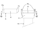
トラップ管14は、断面略円形を成す管体を略U字形状に屈曲させた部材であって、図1、図2における上下及び前後に対して対称形状を成し、その両端には、それぞれ以下に記載する、上記上流側の挿入管部1及び下流側の挿入管部1に対応する受入管部3を備えてなる。
受入管部3は、鍔部2よりも端部側の挿入管部1が挿入される、上下に直線形状を成す、円筒形状部分であり、またその側面に、周縁に沿って内外を貫通する溝部4を有してなる。
また、該溝部4に隣接して、溝部4の上方と下方とを繋ぐ柱部分4aが備えられてなる。柱部分4aは、受入管部3の円筒形状の中心軸に対して180度を成す対称位置に二か所備えられてなる。
柱部分4aは、受入管部3の円形の壁面部分から、壁面の外側、即ち水平方向に向かって若干突出している。
この水平方向の突出の程度は、施工完了時、後述する接続部材5の開放端部9の外側面にほぼ連続する程度である。柱部分4aの外側面は、施工完了時、挿入管部1の鍔部2よりも外側に位置するように構成されており、この鍔部2よりも外側の柱部分4aは、図1のように、施工完了時接続部材5の上面とほぼ同じ高さ(カバー部13の下面とほぼ同じ高さ)の位置となるように突出して構成されている。
一方で、柱部分4aは、受入管部3の内径方向に向かっては突出しておらず、受入管部3の内側面の断面は、図22のように略円形を保っている。これにより、トラップ管14の受入管部3に挿入された、鍔部2よりも端部側の挿入管部1は、管体の軸を中心に自在に回転させることができる。
尚、本実施例では、一つの受入管部3に二つの溝部4と柱部分4aとが形成されている。トラップ管14にはその両端に計二つの受入管部3を設けているため、トラップ管14全体では計4つの溝部4及び柱部分4aを有することとなる。本実施例では、図2等より明らかなように、この4つの柱部分4aが管体の中心軸を含む面に沿うようにして、直線状に配置されている。
また、柱部分4aの、軸方向に垂直な面での断面形状は、図14等からも明らかなように、管体の外側となる外側面に傾斜乃至円弧を備えた形状となっている。
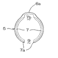
接続部材5は、施工完了時の挿入管部1及び受入管部3の軸方向視、略C字形状を成す部材であって、以下に記載する側壁部6及び爪部7等の各部分を一体にして構成されてなる。尚、接続部材5は、軸方向に垂直な面、及び中心軸と開放端部9の中心とを繋ぐ面とに対して対称形状を成すように構成されてなる。例えば、図6に基づけば、接続部材5は「上下対称」であり「左右対称」となる。以下説明を容易にするため、図6に基づいて接続部材5の「上下」および「左右」を記載する。また、以下の説明では、便宜上「上方の爪部7」「下方の爪部7」といった記載を行うが、接続部材5は上下対称且つ左右対称であるため、回転させて上下(又は/及び左右)を入れ替えても形状・機能的には何ら差異は無い。また、本実施例では、挿入管部1及び受入管部3が2組あることから、接続部材5も同一形状・構成のものを2つ使用する。
側壁部6は、上方視、略C字形状を成す壁面部分であり、C字形状の端部である開放端部9の中心軸を挟んで対向位置に、柱部分4aとほぼ同じ幅で、他の部分よりも外周方向に突出した凸部6aを備えてなる。この凸部6aは、施工完了時、柱部分4aの外側面に内側面が当接するように配置される。
爪部7は、側壁部6の、上端及び下端であって、凸部6a以外の部分から内径方向に向かって突出して形成されてなり、接続時において、上方の爪部7が挿入管部1の鍔部2の裏面側に、下方の爪部7が受入管部3の溝部4に、それぞれ嵌入するように構成されてなる。
爪部7の内径は、挿入管部1の鍔部2以外の部分の外径とほぼ同じ径であり、また挿入管部1には、その内外に貫通する溝部4が形成されている。これによって、施工完了時、いずれの爪部7も、その内側面が挿入管部1の外側面に当接するように配置される。
また、爪部7には、図6等より明らかなように、上側の爪部7においてはその上面となる面に、接続部材5の内径側ほど下方に向かう傾斜面8を設けてなる。上記のように接続部材5は上下対称であり、従って、下側の爪部7においては、その下面となる面に、接続部材5の内径側ほど上方に向かう傾斜面8を設けてなる。
また、上方視、接続部材5の内側面であって、凸部6aを起点に内径側ほど幅広になるよう構成された凹部7bを上下の爪部7にそれぞれ備えてなる。前述のように、凸部6aの幅は柱部分4aの幅とほぼ同じ幅であり、接続部材5は図 の左右において対称形状に構成されてなるため、凹部7bは、凸部6aを短辺とし内径側ほど幅広になる、略等脚台形形状を成す。このように構成された凹部7bは、施工完了時柱部分4aに干渉せず、柱部分4aを外周方向に迂回するように配置・形成されてなる。
開放端部9は、C字形状の開放された端部となる部分である。該開放端部9の内、爪部7以外の部分、すなわち側壁部6の開放端部9の部分は、図7のように、外方向に向かって開くような若干の傾斜を設けてなる。また、側壁部6分の開放端部9の幅は、柱部分4aのおよそ二倍程度の幅を有してなる。
これに対し、上下の爪部7では、開放端部9の幅は、ほぼ柱部分4aと同じで若干だけ幅広である。このように、開放端部9の内、側壁部6に比べて爪部7だけが溝部4及び鍔部2の外径形状に沿うように突出してなり、この突出部分が、ガイド構造としての突起部7aを形成してなる。
尚、挿入管部1の外側面の直径は、突起部7aまた側壁部6の開放端部9の幅よりも広く、施工完了後には、開放端部9を拡開する十分な応力が加わらない限り、接続部材5が挿入管部1また受入管部3から抜脱することは無い。
また、上流側の挿入管部1及び下流側の挿入管部1と受入管部3の内、接続部材5によって覆われる部分、具体的には挿入管部1のカバー部13と鍔部2との間の側面、鍔部2の上面及び側面、受入管部3の、柱部分4aを除く溝部4よりも上方の側面及び上面には、図示しないが、表示構造としての赤色の塗装が行われている。
尚、詳述しないが、本発明においては、水密的な接続が必要な箇所においては、適宜パッキングP等を用い、水密的な接続を行っている。
Embodiments of the present invention will be described below with reference to the drawings. In the following description of the embodiment, the up / down direction is described based on the top and bottom at the completion of implementation of the embodiment. However, in the practice of the invention, the direction must always be determined in accordance with the top and bottom in the description. However, the upper and lower sides may be changed in the horizontal direction according to the embodiment of the invention.
The drainage pipe adopting the pipe connection structure of the embodiment of the present invention shown in FIG. 1 to FIG. 31 is a basin as a drainage device described below, a
The wash basin is composed of a wash bowl W made of a box having an upper opening as a tank body, and a cabinet (not shown) on which the wash bowl W is mounted. Further, the bottom surface of the wash bowl W is provided with a mounting hole for attaching the
The
Further, the
The drain plug joint 12 is a straight pipe that connects the
Further, an
If it explains in full detail, the lower part of the drain plug joint 12 is made into a cylindrical shape, and the
Moreover, the
The J-shaped
The
Further, the
The
The receiving
Further, adjacent to the
The
The extent of this horizontal protrusion is such that it is substantially continuous with the outer surface of the open end 9 of the connecting
On the other hand, the
In the present embodiment, two
Further, the cross-sectional shape of the
The connecting
The
The
The inner diameter of the
Further, as is apparent from FIG. 6 and the like, the
Further, the upper and
The open end 9 is a portion that becomes a C-shaped open end. Of the open end portion 9, the portion other than the
On the other hand, in the upper and
In addition, the diameter of the outer side surface of the
Of the upstream
Although not described in detail, in the present invention, a watertight connection is made by using a packing P or the like as appropriate at a place where a watertight connection is required.
上記のように構成した管体の接続構造を採用した排水配管は、以下のようにして槽体である洗面台の洗面ボウルWに施工される。
尚、以下の施工手順等の説明においては、説明を容易にするため、トラップ管14の受入管部3の内、排水栓継手12が接続される側の受入管部3を「上流側」、J字管15を接続される側の受入管部3を「下流側」と、必要に応じて記載する。但し、トラップ管14は上記のように図 の左右及び前後に対して対称形状を成してなり、機能・形状的には2つあるうちのどちらの受入管部3を上流側又は下流側としても構わない。
The drainage pipe adopting the pipe connecting structure configured as described above is applied to the wash bowl W of the wash basin which is a tank body as follows.
In the following description of the construction procedure and the like, for the sake of easy explanation, the receiving
工場等、施工現場に搬入・出荷する前の段階で、以下のような手順に沿ってトラップ管14とJ字管15の接続を行う。
まず、トラップ管14のいずれか一方の端部にある受入管部3(これが「下流側」の受入管部3になる)に、図9から図13で示したように、J字管15の挿入管部1を、受入管部3の上端面に受入管部3の鍔部2下面が当接するまで挿入する。
この状態では、当然ながら、第二の挿入管部1と、第二の挿入管部1が挿入された下流側受入管部3に施された、表示構造としての赤色の塗装を目視することができる。
次に、接続部材5を、U字形状を成すトラップ管14の側面方向からJ字管15の挿入管部1及び下流側の受入管部3に嵌入させる。
詳述すると、接続部材5の開放端部9が下流側の受入管部3の柱部分4aを向き、接続部材5を受入管部3の中心軸に対して側方になる位置に配置した上で、接続部材5を受入管部3側に移動させる。
すると、図15に示したように、まず接続部材5の上下に備えられたガイド構造としての突起部7aが、挿入管部1の鍔部2裏側、即ち鍔部2の上面側と、受入管部3の溝部4に嵌入する。この時点では、接続部材5の開放端部9は、弾性によって拡開していないため、嵌入に際して特に無理な応力を加える必要は無い。よって、接続部材5を適正な位置、具体的には上方の突起部7aを鍔部2の上面側に、下方の突起部7aを受入管部3の溝部4に、それぞれ嵌入することは極めて容易且つ確実に行うことができる。
この状態では、上方の突起部7aの先端は鍔部2上方の、下方の突起部7aの先端は溝部4を貫通して鍔部2下方の、それぞれ挿入管部1外側面に接する。また接続部材5の側壁部6の開放端部9の側面が、鍔部2側面及び溝部4より上方の受入管部3側面に接する。
そのまま接続部材5の嵌入を進めると、図16のように開放端部9の突起部7a及び側壁部6が挿入管部1また受入管部3の外側面の円弧に沿って移動するため、開放端部9が拡開を始める。この際には、接続部材5が有する樹脂弾性によって、開放端部9の拡開を防ぎ、開放端部9を当初の幅まで閉じようとする応力が働き、接続部材5を移動させるための力とは真逆の方向に作用するため、接続部材5を移動させるためには、開放端部9を当初の幅まで閉じようとする応力に抗して充分な力を、作業者は加える必要がある。このように、移動を進めるため力を加えて作業を行うと、その分力の方向のコントロールが難しくなり、移動とは逆方向の応力が働いていることと合わせて、接続部材5が適正な位置からずれようとする方向に応力が向く場合があるが、本実施例では、ガイド機構としての突起部7aが、鍔部2及び溝部4に沿って配置され、接続部材5の移動の方向が、上方や下方にずれることを防ぐように構成されている。このため、接続部材5に移動の応力を加えると、上下に位置がぶれることなく、確実に適正な位置に接続部材5を移動(嵌入)させることができる。
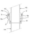
接続部材5の移動(嵌入)が進み、接続部材5の開放端部9が、受入管部3及び挿入管部1の中心軸を超えると、開口端部を閉塞させる方向の応力が、そのまま接続部材5の移動(嵌入)を進ませる方向の応力に変化する。そのまま接続部材5を移動させ、或いは開口端部を閉塞するための応力の作用に任せると、接続部材5は最終的に、図17乃至図19に示したように、挿入管部1及び受入管部3と同心円状態の位置まで移動して移動(嵌入)が終了する。この時には、挿入管部1の鍔部2裏面と受入管部3の溝部4とに、接続部材5の爪部7がそれぞれ嵌入して係合し、挿入管部1及び受入管部3が回転可能且つ抜脱不可能な状態にて接続される。このようにして、トラップ管14とJ字管15の接続が完了する。
この状態では、J字管15の挿入管部1と、下流側の受入管部3に施された、表示構造としての赤色の塗装は、接続部材5に覆われるため、目視することができなくなり、これによって接続が適正に行われたことを確認することができる。
上記のように、トラップ管14とJ字管15を接続した上で、排水配管の各部材を施工現場に搬入する。
The
First, as shown in FIG. 9 to FIG. 13, the J-shaped
In this state, of course, it is possible to visually observe the red coating as the display structure applied to the second
Next, the connecting
More specifically, the open end 9 of the connecting
Then, as shown in FIG. 15, first,
In this state, the tip of the
If the fitting of the connecting
When the movement (insertion) of the connecting
In this state, the red coating as the display structure applied to the
As described above, after connecting the
施工現場においては、以下のようにして、排水配管の施工作業を行う。
まず、排水栓10を、洗面ボウルWの取付孔に上方から挿通し、フランジ部10aの下面が取付孔の周縁上面に当接するようにする。
次に、排水栓10の雄ネジに、排水栓継手12の雌ネジを螺合させると、取付孔の周縁を、フランジ部10aの下面と、排水栓継手12の上面とで強く挟持することができ、排水栓10及び排水栓継手12を洗面ボウルWの取付孔に取り付けることができる。
次に、トラップ管14の、J字管15が接続されていない側の端部、即ち上流側の挿入管部1に、未使用の接続部材5を嵌入する。詳述すると、接続部材5の開放端部9が、上流側の受入管部3の柱部分4aを向き、接続部材5を受入管部3の中心軸に対して側面になる位置に配置した上で、接続部材5を受入管部3側に移動させる。
すると、図23に示したように、まず接続部材5の上下に備えられたガイド構造としての突起部7aの内の下側の突起部7aが、受入管部3の溝部4に嵌入する。この時点では、接続部材5の開放端部9は、弾性によって拡開していないため、嵌入に際して特に無理な応力を加える必要は無い。よって、接続部材5の下方の突起部7aを受入管部3の溝部4に嵌入することは極めて容易である。
この状態では、下方の突起部7aが溝部4に嵌ったまま、接続部材5側壁部6の開放端部9端面が、溝部4より上方の受入管部3側面に接する。そのまま接続部材5の嵌入を進めると、図24に示したように、開放端部9の突起部7a及び側壁部6が挿入管部1また受入管部3の外側面の円弧に沿って移動するため、開放端部9が拡開を始める。この際には、接続部材5が有する樹脂弾性によって、開放端部9の拡開を防ぎ、開放端部9を当初の幅まで閉じようとする応力が、接続部材5を移動させるための力とは真逆の方向に作用するため、接続部材5を移動させるためには、開放端部9を当初の幅まで閉じようとする応力に抗して充分な力を、作業者は加える必要がある。このように、移動を進めるため力を加えて作業を行うと、その分力の方向のコントロールが難しくなり、移動とは逆方向の応力が働いていることと合わせて、接続部材5が適正な位置からずれようとする方向に応力が向く場合があるが、本実施例では、ガイド機構としての突起部7aが、溝部4に沿って配置され、接続部材5の移動の方向が、上方や下方にずれることを防ぐように構成されている。このため、接続部材5に移動の応力を加えると、上下に位置がぶれることなく、確実に適正な位置に接続部材5を移動(嵌入)させることができる。
接続部材5の移動(嵌入)が進み、接続部材5の開放端部9が、受入管部3の中心軸を超えると、開口端部を閉塞させる方向の応力が、そのまま接続部材5の移動(嵌入)を進ませる方向の応力に変化する。そのまま接続部材5を移動させ、或いは開口端部を閉塞するための応力の作用に任せると、図25乃至図27に示したように、接続部材5は最終的に、受入管部3と同心円状態の位置まで移動して移動(嵌入)が終了する。この時には、受入管部3の溝部4に、接続部材5の爪部7が嵌入して係合し、接続部材5が受入管部3に抜脱不可能な状態となる。
J字管15の下流側の端部を、弾性・可撓性を有するゴムソケット等の配管部材を利用して、床下配管等の下水側の配管に接続した後、排水栓10接続管とトラップ管14の上流側端部を接続する。
詳述すると、まず、トラップ管14とJ字管15、またJ字管15と床下配管との接続部分において、図28に示したように、それぞれの接続箇所を回転等によって位置調整し、排水栓継手12の挿入管部1の直下に、トラップ管14の上流側の受入管部3が同心円状となるよう配置する。
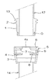
次に、トラップ管14及びJ字管15をそのまま上方に移動させると、図29に示したように、排水栓継手12の鍔部2の下端が、上流側の受入管部3に嵌入されている接続部材5の上面に当接する。接続部材5の上面には、管体の中心軸に向かうほど下方に向かう傾斜面8が形成されてなるため、トラップ管14の上昇を継続させると、受入管部3を上昇させる応力の一部が、傾斜面8の作用により、接続部材5の開口端部を拡開させ、接続部材5の側壁部6の円弧の径を拡大させるように作用する。そのままトラップ管14を上昇させると、最終的には、接続部材5が拡径して、接続部材5の爪部7内周面の径が、排水栓継手12の挿入管部1の鍔部2外周面の径よりも大径となり、鍔部2が上方の爪部7を乗り越え、上流側の受入管部3に係合する接続部材5の上方の爪部7が、排水栓継手12の挿入管部1の鍔部2よりも上方に達する。
この時点で、接続部材5の爪部7が縮径し、爪部7が鍔部2裏面に嵌入することで、爪部7と鍔部2とが係合し、挿入管部1及び受入管部3が回転可能且つ抜脱不可能な状態にて接続される(状態としては、図18、図19のJ字管15の挿入管部1とトラップ管14の受入管部3の施工完了後の状態と同じとなる)。このようにして、トラップ管14と排水栓10接続管の接続が完了する。
この状態では、排水栓継手12の挿入管部1と、上流側の受入管部3に施された、表示構造としての赤色の塗装は、接続部材5に覆われるため、目視することができなくなり、これによって接続が適正に行われたことを確認することができる。
上記のようにして、本発明の管体の接続構造を採用した排水配管の、槽体である洗面台の洗面ボウルWへの施工が完了する。
At the construction site, drainage pipes are constructed as follows.
First, the
Next, when the female screw of the drain plug joint 12 is screwed into the male screw of the
Next, the
Then, as shown in FIG. 23, first, the
In this state, the open end portion 9 end surface of the
When the movement (insertion) of the connecting
After connecting the downstream end of the J-shaped
More specifically, first, as shown in FIG. 28, the positions of the connection portions of the
Next, when the
At this time, the
In this state, the red coating as the display structure applied to the
As described above, the construction of the drainage pipe adopting the pipe connection structure of the present invention to the wash bowl W of the wash basin which is a tank body is completed.
上記のように施工された洗面台の排水配管において、洗面台を使用し、洗面ボウルW内に排水が生じると、排水は、洗面ボウルW内から排水口11を通過し、排水栓継手12からトラップ管14内部を通過し、更にJ字管15を通過して、最終的に床下配管から下水側に排出される。
また、トラップ管14内部に排水が溜まることで、トラップ管14の排水の流路の一部が満水状態となる。これにより、下水側からの臭気や害虫類の逆流が防止される、トラップ機能を生じる。
In the drainage pipe of the washstand constructed as described above, when drainage occurs in the washbasin bowl W using the washstand, the wastewater passes through the
Further, since the drainage is accumulated in the
上記実施例においては、挿入管部1、受入管部3、接続部材5を、それぞれ軸方向視円形形状に構成し、またOリングOも挿入管部1の周縁に沿って配置したことで、挿入管部1と受入管部3とを、水密的な接続を維持したまま、回動自在に接続することができ、必要に応じて回転させて位置調整等を行うことができる。
In the above embodiment, the
上記本発明の管体の接続構造においては、施工完了時において、挿入管部1の鍔部2裏側から、受入管部3の溝部4までが、接続部材5に覆われることで、接続部分に衝撃が加わっても、接続部材5によって鍔部2裏側から溝部4までが保護され、破損しにくくなる。
鍔部2裏側から溝部4までを覆った接続部材5は、開放端部9を有することで、衝撃を受けても一時的に開放端部9が広がり衝撃を逃がす等、鍔部2裏側や溝部4よりも破損しにくい構造とすることができる。特に本実施例では、鍔部2の上方にカバー部13を設けたことで、接続部材5自体にも衝撃が加えられ難い構造としている。
また、接続部材5を挿入管部1または受入管部3に嵌入する際、接続部材5に係合される鍔部2及び溝部4が露出しているため、接続部材5の嵌入作業は、嵌入する箇所を視認しつつ行うことができ、作業が極めて容易である。
また、ガイド構造としての突起部7aを設け、この突起部7aを鍔部2裏面また溝部4に嵌入することから、接続部材5の弾性に抗して開放端部9を拡開し、接続部材5を挿入管部1または受入管部3に嵌入する際、接続部材5の方向がぶれることが無く、嵌入する作業を極めて容易に行うことができる。
また、ガイド構造としての突起部7aは、溝部4及び鍔部2の外径形状に沿う形状であるため、従来例のガイド構造と比較し、この突起部7aが接続構造の外側方向に突出することが無く、施工者や使用者が誤って触れることが起こりにくい形状となっている。このため、施工者や使用者が怪我を負ったり、誤って触れたことで接続部材5が外されて管体の接続が解除されてしまう、と言った問題が生じにくい。特に本実施例では、前述のように、柱部分4aの水平方向の突出の程度が、接続部材5の開放端部9の外側面にほぼ連続するように構成されているため、開放端部9に手が触れたりして施工者や使用者が怪我を負ったり、接続部材5が外されて管体の接続が解除されてしまうことが、より一層生じにくくなっている。
特に本実施例では、鍔部2の上方にカバー部13を設けたことで、より一層接続部材5に施工者や使用者が触れにくい構造としている。
また、本実施例では溝部4を、受入管部3の内外を貫通するように構成したことで、貫通しない溝部4の場合と比較し、接続構造部分の外径を小径とできる。これは、狭い個所に配管を施工しなければならない場合や、本実施のトラップ管14の両端のように、管体をU字形状に屈曲させた結果、隣接する管体の隙間が狭くなってしまった場合等に、部材をコンパクトにするために有効である。
また、受入管部3には柱部分4aを設けてなり、施工完了時、この柱部分4aには接続部材5の開放端部9および凹部7bが配置される。開放端部9の一端に施工者や使用者の指先が触れるなどして、開放端部9が拡開する外側方向に応力が加わった場合、開放端部9の他端が柱部分4aの端部に当たって接続部材5が鍔部2や溝部4に沿って回転することができない為、図31のように、爪部7の係合が外れかけるとともに、凹部7bの角部分が柱部分4aの外側面に接する場合がある。
この場合に、本実施例では、接続部材5に設けた凹部7bに対し、該凹部7bが、内側ほど幅広になるよう構成したことで、角部分が90度を超える角度、いわゆる鈍角となり、柱部分4aの外側面に角部分が引っかかって留まり、挿入管部1と受入管部3との接続が不完全となったまま維持される、ということが無くなった。即ち、接続部材5が衝撃を受けるなどして一時的に適正な接続状態でなくなったとしても、柱部分4aの外側面に角部分が引っからずスムーズに滑るため、接続部材5の弾性を利用し、元の適正な嵌合状態に復帰することができる。
また、本発明においては、表示構造である赤色の塗装を利用して、接続が適正に行われているかどうかを確認することができる。管体の接続が適正に行われている場合は、施工完了時に赤色の表示を目視することは無い。接続部材5を嵌入する位置を誤り、例えば接続部材5の上方の突起部7aを、カバー部13と鍔部2の間に挿入した場合では、受入管部3の溝部4よりも上方の側面部分が露出し、そこに塗られている赤色の塗装が目視され確認されるため、接続部材5による接続が適正に行われていないことが確認できる。
In the connection structure of the tubular body of the present invention, when the construction is completed, from the back side of the
The
Further, when the connecting
Further, since the
Further, since the protruding
In particular, in the present embodiment, the
Moreover, in the present Example, since the
Further, the receiving
In this case, in this embodiment, the
Moreover, in this invention, it can be confirmed whether the connection is performed appropriately using the red coating which is a display structure. If the pipes are properly connected, the red display will not be seen at the completion of construction. In the case where the position where the connecting
上記実施例において、配管内部の清掃や、部材が破損し交換等にて対応を行う場合等では、挿入管部1と受入管部3との接続を解除し、清掃また修理を行うことができる。この時は、接続部材5を開放端部9を介して配管から抜脱することで、挿入管部1と受入管部3との接続を解除することができる。
In the above embodiment, when the inside of the pipe is cleaned or when a member is damaged and replaced by replacement, etc., the connection between the
本発明の実施例は以上のようであるが、本発明は上記実施例に限定される物ではなく、主旨を変更しない範囲において自由に変更が可能である。
例えば、上記実施例では、本発明の管体の接続構造を、洗面台の配管構造に採用して構成してなるが、本発明は上記実施例に限定されるものではなく、一般的な管体の接続に支障なく利用することができる。また、洗面台や浴槽・浴室、また洗濯機用防水パン等の様々な排水機器の配管構造、また排水装置の取り付け構造に採用しても構わない。
The embodiments of the present invention are as described above. However, the present invention is not limited to the above-described embodiments, and can be freely changed without departing from the scope of the present invention.
For example, in the above embodiment, the pipe connection structure of the present invention is adopted in the piping structure of the wash basin, but the present invention is not limited to the above embodiment, and a general tube It can be used without hindrance to body connection. Moreover, you may employ | adopt for the piping structure of various drainage apparatuses, such as a washstand, a bathtub, a bathroom, and the waterproof pan for washing machines, and the attachment structure of a drainage device.
また、上記実施例では、管体は全て円形形状であるが、管体を軸方向視四角形形状等、円形以外の形状にて構成しても構わない。 Moreover, in the said Example, although a tubular body is circular shape altogether, you may comprise a tubular body in shapes other than circular shapes, such as a square shape in an axial direction view.
また、上記実施例では、目印構造は印刷によって構成してなるが、本発明は上記実施例に限定されるものではなく、例えば他の部材とは異なる色調で成形した樹脂材を組み合わせるなどで表示するようしても構わない。また、接続部材5の側壁部6に開口を設け、施工完了時、適正であれば、該窓から表示が見えるようにして、「施工が適正であれば目印構造が視認できる」構造としても構わない。
Further, in the above embodiment, the mark structure is formed by printing. However, the present invention is not limited to the above embodiment, and is displayed by combining, for example, resin materials molded in a color tone different from other members. It doesn't matter if you do. In addition, an opening may be provided in the
また、上記実施例では、上流側の挿入管部1と受入管部3との接続では、受入管部3に接続部材5を嵌入した後に、挿入管部1を受入管部3に挿入し、下流側の挿入管部1と受入管部3との接続では、受入管部3に挿入管部1を挿入した後に、接続部材5を挿入管部1及び受入管部3に嵌入するように、接続作業を行っているが、本発明は特にこれらの手順について何ら限定を行うものではない。
上記実施例においては、接続後に挿入管部1と受入管部3とを回転させて位置調整する場合には受入管部3に挿入管部1を挿入した後接続部材5を嵌入し、接続後に挿入管部1と受入管部3とをほぼ回転させない場合には受入管部3に接続部材5を嵌入した後挿入管部1を挿入する、という要領にて判断しているが、必ずしもこの要領に従う必要も無く、施工後に受入管部3をそれぞれの接続箇所に対し、受入管部3に挿入管部1を挿入した後に、接続部材5を嵌入するようにして接続を行うか、または受入管部3と挿入管部1のいずれか一方に接続部材5を嵌入した後に、挿入管部1を受入管部3に挿入するようにして接続を完了させるかは、状況や必要に応じて、施工者等が作業を容易にできる方を、自由に選択するものである。
また傾斜面8についても、上記実施例においては爪部7上に設けているが、必要に応じて挿入管部1や受入管部3、爪部7のいずれか一つまたはそれぞれに設けて対応するようにしても構わない。
Moreover, in the said Example, in the connection of the upstream
In the above embodiment, when the
In addition, the
1 挿入管部 2 鍔部
3 受入管部 4 溝部
4a 柱部分 5 接続部材
6 側壁部 6a 凸部
7 爪部 7a 突起部
7b 凹部 8 傾斜面
9 開放端部 10 排水栓
10a フランジ部 11 排水口
12 排水栓継手 13 カバー部
14 トラップ管 15 J字管
O Oリング P パッキング
W 洗面ボウル
DESCRIPTION OF
Claims (6)
筒形状にして、その側面に、周縁に沿って設けられた鍔部を有する挿入管部と、
鍔部よりも端部側の挿入管部が挿入される、筒形状にして、その側面に周縁に沿って内外を貫通する溝部を有する受入管部と、
挿入管部の鍔部よりも端部側が、受入管部に挿入された状態で、鍔部及び溝部に係合して、挿入管部が受入管部から抜脱することを防止する爪部を有する接続部材と、
からなり、
更に接続部材は、開放端部を有する、管体の軸方向視略C字形状であって、
略C字形状を成す壁面部分である側壁部を備え、
爪部は、該側壁部の軸方向の両端に、内径方向に向かって突出して形成され、
爪部の内径は、挿入管部の鍔部以外の部分の外径とほぼ同じ径であり、
接続時において、一方の端部の爪部が挿入管部の鍔部に、他方の端部の爪部が受入管部の溝部に、それぞれ係合するように構成されてなる管体の接続構造。 It is a connection structure of pipes for connecting pipes,
An insertion tube portion having a cylindrical shape and having a flange portion provided along the periphery on the side surface;
An insertion tube portion into which the insertion tube portion on the end side than the flange portion is inserted, has a cylindrical shape, and a receiving tube portion having a groove portion penetrating the inside and outside along the peripheral edge on the side surface;
A claw portion that prevents the insertion tube portion from being pulled out of the receiving tube portion by engaging the flange portion and the groove portion with the end portion side of the insertion tube portion being inserted into the receiving tube portion. A connecting member having
Consists of
Further, the connecting member has a substantially C shape in the axial direction of the tubular body having an open end,
A side wall portion that is a wall surface portion having a substantially C shape is provided.
The claw portions are formed at both ends in the axial direction of the side wall portion so as to protrude toward the inner diameter direction,
The inner diameter of the claw portion is substantially the same diameter as the outer diameter of the portion other than the collar portion of the insertion tube portion,
At the time of connection, the tube connecting structure is configured such that the claw portion at one end engages with the flange portion of the insertion tube portion, and the claw portion at the other end engages with the groove portion of the receiving tube portion. .
該接続部材の開放端部に、溝部又は鍔部裏側のいずれか一方又は両方に嵌入するガイド構造を備えたことを特徴とする、請求項1に記載の管体の接続構造。 The connecting member is inserted into the tube body from the side surface direction through the open end,
The tube connection structure according to claim 1, further comprising a guide structure fitted into one or both of the groove portion and the back side of the flange portion at an open end portion of the connection member.
管体の軸方向の溝部両端を繋ぐ柱部分を設け、
接続部材の内側面に、接続時上記柱部分を管体の外側方向に迂回する凹部を設け、
該凹部が、内側ほど幅広になるよう構成されたことを特徴とする、請求項1乃至請求項4のいずれか一つに記載の管体の接続構造。 On the groove provided in the receiving pipe part ,
A column portion is provided to connect both ends of the axial groove portion of the tubular body,
Provided on the inner surface of the connecting member a recess that bypasses the column portion in the outer direction of the tube when connected,
The tube connecting structure according to any one of claims 1 to 4 , wherein the concave portion is configured to become wider toward an inner side.
Priority Applications (1)
| Application Number | Priority Date | Filing Date | Title |
|---|---|---|---|
| JP2014050917A JP6389991B2 (en) | 2014-03-13 | 2014-03-13 | Tube connection structure |
Applications Claiming Priority (1)
| Application Number | Priority Date | Filing Date | Title |
|---|---|---|---|
| JP2014050917A JP6389991B2 (en) | 2014-03-13 | 2014-03-13 | Tube connection structure |
Publications (2)
| Publication Number | Publication Date |
|---|---|
| JP2015175132A JP2015175132A (en) | 2015-10-05 |
| JP6389991B2 true JP6389991B2 (en) | 2018-09-19 |
Family
ID=54254584
Family Applications (1)
| Application Number | Title | Priority Date | Filing Date |
|---|---|---|---|
| JP2014050917A Active JP6389991B2 (en) | 2014-03-13 | 2014-03-13 | Tube connection structure |
Country Status (1)
| Country | Link |
|---|---|
| JP (1) | JP6389991B2 (en) |
Family Cites Families (5)
| Publication number | Priority date | Publication date | Assignee | Title |
|---|---|---|---|---|
| JPH058170U (en) * | 1991-07-12 | 1993-02-05 | 株式会社リケン | Pipe fitting |
| JP4153264B2 (en) * | 2002-08-28 | 2008-09-24 | アロン化成株式会社 | Synthetic resin C-ring and corrugated flexible pipe joint using the same |
| JP4336632B2 (en) * | 2004-08-25 | 2009-09-30 | 太田 育實 | Connection structure of drain plug device |
| JP5412632B2 (en) * | 2008-10-17 | 2014-02-12 | 丸一株式会社 | Remote control drain plug device and its construction method |
| JP5953132B2 (en) * | 2012-06-07 | 2016-07-20 | Toto株式会社 | Operating device |
-
2014
- 2014-03-13 JP JP2014050917A patent/JP6389991B2/en active Active
Also Published As
| Publication number | Publication date |
|---|---|
| JP2015175132A (en) | 2015-10-05 |
Similar Documents
| Publication | Publication Date | Title |
|---|---|---|
| US20080098517A1 (en) | Method and Associated Apparatus for Assembling and Testing a Plumbing System | |
| JP6446629B2 (en) | Tube connection structure | |
| US20120005824A1 (en) | Method and Associated Apparatus for Assembling and Testing a Plumbing System | |
| JP2015507113A (en) | Installation structure and installation method of pop-up device for basin | |
| JP5613886B2 (en) | Piping structure of tank body | |
| JP6389991B2 (en) | Tube connection structure | |
| KR20100127461A (en) | Draining apparatus for washstand | |
| JP2015025525A (en) | Connection structure of shell | |
| JP6229118B2 (en) | Piping member connection structure | |
| JP6029130B2 (en) | Drain trap | |
| JP3689233B2 (en) | Drainage equipment | |
| JP2007138654A (en) | Drain trap | |
| JP4713910B2 (en) | Piping fixture | |
| JP2016003702A (en) | Shell connection structure | |
| JP6909451B2 (en) | Connection structure of the tube | |
| JP7016492B2 (en) | Tube with connection mechanism | |
| JP2018031196A (en) | Drain piping and construction method for the same | |
| JP6488476B2 (en) | Tube connection structure | |
| JP6511668B2 (en) | Tube connection structure | |
| WO2019211648A1 (en) | Waterless waste valve | |
| KR101694497B1 (en) | Apparatus for coupling drainpipe with trap-pipe | |
| JP2006118224A (en) | Water trap for tank body | |
| KR102105499B1 (en) | One-touch nut for sanitary appliance | |
| JP2016065411A (en) | Water trap | |
| JP2010127049A (en) | Drain pipe having drain adaptor member |
Legal Events
| Date | Code | Title | Description |
|---|---|---|---|
| A521 | Written amendment |
Free format text: JAPANESE INTERMEDIATE CODE: A523 Effective date: 20151005 |
|
| A621 | Written request for application examination |
Free format text: JAPANESE INTERMEDIATE CODE: A621 Effective date: 20170228 |
|
| A977 | Report on retrieval |
Free format text: JAPANESE INTERMEDIATE CODE: A971007 Effective date: 20171128 |
|
| A131 | Notification of reasons for refusal |
Free format text: JAPANESE INTERMEDIATE CODE: A131 Effective date: 20171212 |
|
| A521 | Written amendment |
Free format text: JAPANESE INTERMEDIATE CODE: A523 Effective date: 20180130 |
|
| TRDD | Decision of grant or rejection written | ||
| A01 | Written decision to grant a patent or to grant a registration (utility model) |
Free format text: JAPANESE INTERMEDIATE CODE: A01 Effective date: 20180612 |
|
| A61 | First payment of annual fees (during grant procedure) |
Free format text: JAPANESE INTERMEDIATE CODE: A61 Effective date: 20180620 |
|
| R150 | Certificate of patent or registration of utility model |
Ref document number: 6389991 Country of ref document: JP Free format text: JAPANESE INTERMEDIATE CODE: R150 |
|
| R250 | Receipt of annual fees |
Free format text: JAPANESE INTERMEDIATE CODE: R250 |