JP2007138654A - Drain trap - Google Patents
Drain trap Download PDFInfo
- Publication number
- JP2007138654A JP2007138654A JP2005337030A JP2005337030A JP2007138654A JP 2007138654 A JP2007138654 A JP 2007138654A JP 2005337030 A JP2005337030 A JP 2005337030A JP 2005337030 A JP2005337030 A JP 2005337030A JP 2007138654 A JP2007138654 A JP 2007138654A
- Authority
- JP
- Japan
- Prior art keywords
- hose
- drainage
- drain
- drain trap
- joint
- Prior art date
- Legal status (The legal status is an assumption and is not a legal conclusion. Google has not performed a legal analysis and makes no representation as to the accuracy of the status listed.)
- Pending
Links
Images

Landscapes
- Sink And Installation For Waste Water (AREA)
Abstract
Description
本発明は、床面の排水口内などに設置され、洗濯機などの排水が強制排水される排水トラップに関するものである。 The present invention relates to a drain trap that is installed in a drain outlet of a floor surface and forcibly drains drainage of a washing machine or the like.
従来、洗い場、浴室、洗面所、洗濯機、或いは各種キャビネットなどからの排水は、自然排水が一般的であったが、近年、ドラム式洗濯機や浄化装置が流し台に設置されたものでは、排水に異物が混入して排水ホースが詰まるのを防止するために排水ポンプを設置して排水を強制排水することがある。このような場合、排水ホースには高い水圧が加わることになり、排水ホースがホースジョイントから抜け落ちる可能性がある。 Conventionally, drainage from washing places, bathrooms, washrooms, washing machines, or various cabinets has been natural drainage, but in recent years, drum-type washing machines and purifiers have been installed in sinks. In order to prevent foreign matter from being mixed into the drainage hose, a drainage pump may be installed to forcibly drain the drainage. In such a case, a high water pressure is applied to the drainage hose, and the drainage hose may fall out of the hose joint.
従来の排水ホースの抜けを防止する排水トラップの一例としては、図3に示すものがある。同図において、床Fに設けた開口部Pに排水管Cが配設され、排水カップ1にはその上部に排水がオーバフローする越流孔1aが設けられ、底部に排水ホース受部1bが設けられ、排水管Cの開口端を覆って排水カップ受部2が床F面に設けられ、排水カップ受部2の段差部に排水カップ1が載置されている。排水カップ受部2に嵌合するパッキンホルダー4にゴムパッキン5が設けられ、排水ホース3がゴムパッキン5の開口閉鎖部材5aを貫通して排水ホース3の先端部が排水ホース受部1bに接触している。排水ホース3は排水カップ1の底部まで差し込まれることにより開口閉鎖部材5aに嵌合し、容易に抜けないようにするとともに、排水ホース3を残留排水内に水没させて水封機構を構成している。(例えば、特許文献1参照)
An example of a drain trap for preventing a conventional drain hose from coming off is shown in FIG. In the figure, a drain pipe C is provided in an opening P provided in a floor F, a
上記従来例の排水トラップは、排水ホースが水封機構に組み込まれた構成であり、自然排水では排水ホースが外れないような構造である。この排水トラップは排水が排水カップの底面から直上への流れと急峻に流れの方向を変えて越流孔から排水管に流れ落ちる構造であるので、強制排水のように水圧を加えて排水する場合、排水ホースには上方に持ち上げられるような力が加わり、排水ホースが排水カップから徐々に抜け出して外れるおそれがあった。また、他の従来例としては、排水トラップに屈曲したホースジョイントが設けられ、ホースジョイントの先端部に排水ホースを差し込んで固定バンドで排水ホースを固定するものがあるが、同様に水圧により排水ホースが徐々に抜け落ちる可能性があった。 The drain trap of the conventional example has a structure in which a drain hose is incorporated in a water seal mechanism, and has a structure in which the drain hose cannot be detached by natural drainage. This drain trap has a structure in which drainage flows sharply from the bottom of the drain cup to the drain pipe by changing the direction of flow sharply, so when draining by applying water pressure like forced drainage, The drain hose is subjected to a force that lifts upward, and the drain hose may gradually come out of the drain cup and come off. As another conventional example, a bent hose joint is provided in the drain trap, and the drain hose is inserted into the tip of the hose joint and the drain hose is fixed with a fixing band. Could fall out gradually.
本発明は、上述のような課題に鑑みなされたものであり、強制排水のように排水に水圧が加えられたとしても排水ホースがホースジョイントから抜ける落ちることがない排水トラップを提供することを目的とするものである。 The present invention has been made in view of the problems as described above, and an object of the present invention is to provide a drain trap in which a drain hose does not fall out of a hose joint even when water pressure is applied to the drain as in forced drain. It is what.
本発明は、上述の課題を解決したものであり、請求項1の発明は、床面に開口する排水管内に挿入して設置する排水トラップにおいて、
残留排水により水封して臭気を遮断するための排水トラップ本体と、
該排水トラップ本体を支持する排水トラップ本体受部と、
該排水トラップ本体受部に接続されるホースジョイントと、
該ホースジョイントに設けたテーパー状フランジ部に係合し、該ホースジョイントを前記排水トラップ本体受部に接続するパッキンホルダーとからなり、
前記ホースジョイントの排水ホースの接続部に該排水ホースの蛇腹状部が嵌合する嵌入部が形成され、該ホースジョイントと該排水ホースとの接続部をホースバンド固定金具で緊縮して該ホースジョイントに該排水ホースを接続するようにしたことを特徴とする排水トラップである。
The present invention solves the above-mentioned problem, and the invention of
A drain trap body for sealing with residual waste water and blocking odor,
A drain trap body receiving part for supporting the drain trap body;
A hose joint connected to the drain trap body receiving part;
It consists of a packing holder that engages with a tapered flange provided on the hose joint and connects the hose joint to the drain trap body receiving part,
A fitting portion where the bellows-like portion of the drainage hose is fitted is formed in the drainage hose connection portion of the hose joint, and the connection portion between the hose joint and the drainage hose is tightened with a hose band fixing bracket. The drainage trap is characterized in that the drainage hose is connected to the drainage hose.
また、請求項2の発明は、前記嵌入部が、蛇腹状溝であることを特徴とする請求項1に記載の排水トラップである。
The invention according to
また、請求項3の発明は、前記排水トラップ本体が、前記ホースジョイントからの排水を導くストローと該ストローが挿入され、該ストローにより導かれた排水を排水管に送り込むとともに残留排水により水封して臭気を遮断するための排水カップとからなることを特徴とする請求項1又は2に記載の排水トラップである。
According to a third aspect of the present invention, the drain trap body is inserted with a straw for guiding drainage from the hose joint and the straw, and the drainage guided by the straw is fed into a drain pipe and sealed with residual drainage. The drainage trap according to
また、請求項4の発明は、前記排水トラップ本体が、前記排水カップの軸中心に前記ストローの軸中心が位置するように挿入されていることを特徴とする請求項3に記載の排水トラップである。 According to a fourth aspect of the present invention, in the drain trap according to the third aspect, the drain trap body is inserted so that the axial center of the straw is positioned at the axial center of the drain cup. is there.
また、請求項5の発明は、前記排水カップの底部が、前記ストローから排水される排水を曲面で受けることを特徴とする請求項3又は4に記載の排水トラップである。
The invention of
請求項1の発明では、床面に開口する排水管内に挿入して設置する排水トラップにおいて、
残留排水により水封して臭気を遮断するための排水トラップ本体と、
該排水トラップ本体を支持する排水トラップ本体受部と、
該排水トラップ本体受部に接続されるホースジョイントと、
該ホースジョイントに設けたテーパー状フランジ部に係合し、該ホースジョイントを前記排水トラップ本体受部に接続するパッキンホルダーとからなり、
前記ホースジョイントの排水ホースの接続部に該排水ホースの蛇腹状部が嵌合する嵌入部が形成され、該ホースジョイントと該排水ホースとの接続部をホースバンド固定金具で緊縮して該ホースジョイントに該排水ホースを接続するようにしたことを特徴とする排水トラップであるので、ホースジョイントの内面側に形成された嵌入部に排水ホースの蛇腹状部が嵌合し、かつホースジョイントの先端部をホースバンド金具で緊縮して排水ホースを固定することができ、排水に水圧が加えられて排水されたとしても排水ホースがホースジョイントから抜け落ちることがない。
In the invention of
A drain trap body for sealing with residual waste water and blocking odor,
A drain trap body receiving part for supporting the drain trap body;
A hose joint connected to the drain trap body receiving part;
It consists of a packing holder that engages with a tapered flange provided on the hose joint and connects the hose joint to the drain trap body receiving part,
A fitting portion where the bellows-like portion of the drainage hose is fitted is formed in the drainage hose connection portion of the hose joint, and the connection portion between the hose joint and the drainage hose is tightened with a hose band fixing bracket. The drainage hose is connected to the drainage hose, so that the bellows-like part of the drainage hose is fitted to the insertion part formed on the inner surface side of the hose joint, and the tip of the hose joint The drainage hose can be fixed by tightening with a hose band metal fitting, and even if water pressure is applied to the drainage and drained, the drainage hose does not fall out of the hose joint.
また、請求項2の発明では、前記嵌入部が、蛇腹状溝であることを特徴とする請求項1に記載の排水トラップであるので、ホースジョイントの蛇腹状溝に排水ホースの蛇腹状部が嵌合するので、水圧の加えられた排水であっても排水ホースがホースジョイントから抜け落ちることがない。
In the invention of
また、請求項3の発明では、前記排水トラップ本体が、前記ホースジョイントからの排水を導くストローと該ストローが挿入され、該ストローにより導かれた排水を排水管に送り込むとともに残留排水により水封して臭気を遮断するための排水カップとからなることを特徴とする請求項1又は2に記載の排水トラップであるので、排水ホースからホースジョイントを経て排出される排水は、ストロー部分で殆ど流水抵抗を受けることなく流れて越流孔から排水管内に流れ出し、排水に水圧が加えられて排水されたとしても排水ホースがホースジョイントから抜け落ちることがない。
According to a third aspect of the present invention, the drain trap body is inserted with a straw for guiding drainage from the hose joint and the straw, and the drainage guided by the straw is fed into a drain pipe and sealed with residual drainage. The drainage trap according to
また、請求項4の発明では、前記排水トラップ本体が、前記排水カップの軸中心に前記ストローの軸中心が位置するように挿入されていることを特徴とする請求項3に記載の排水トラップであるので、排水がホースジョイントを経てストローを流下する際の流水抵抗が極めて低いために、排水に水圧が加えられたとしても排水ホースがホースジョイントから抜け落ちることがない。 According to a fourth aspect of the present invention, in the drain trap according to the third aspect, the drain trap body is inserted so that the axial center of the straw is positioned at the axial center of the drain cup. Therefore, since the flowing water resistance when the drainage flows down the straw through the hose joint is extremely low, the drainage hose does not fall out of the hose joint even if water pressure is applied to the drainage.
また、請求項5の発明では、前記排水カップの底部が、前記ストローから排水される排水を曲面で受けることを特徴とする請求項3又は4に記載の排水トラップであるので、ストローから排出される排水が排水カップの底部で流水抵抗を受け難くなり、越流孔に送り込まれて排水され、排水に水圧が加えられたとしても排水ホースがホースジョイントから抜け落ちることがない。 According to a fifth aspect of the present invention, the bottom of the drainage cup is a drainage trap according to the third or fourth aspect, wherein the drainage drained from the straw is received by a curved surface. The drainage hose becomes difficult to receive flow resistance at the bottom of the drainage cup, is sent to the overflow hole and drains, and even if water pressure is applied to the drainage, the drainage hose does not fall out of the hose joint.
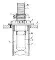
以下、本発明に係る排水トラップの実施形態について図面を参照して説明する。先ず、図1は本発明の一実施形態を示す断面図であり、図2は本発明の他の実施形態を示す要部断面図である。 Hereinafter, an embodiment of a drain trap according to the present invention will be described with reference to the drawings. First, FIG. 1 is a cross-sectional view showing an embodiment of the present invention, and FIG.
本実施形態の排水トラップは、図1に示すように、床Fの設けられた開口部Pに排水管Cが設けられ、排水管Cの開口端に排水トラップ受部4が載置されてネジSにより床F面に固定され、排水トラップ本体1が排水トラップ受部4の段差部に載置されている。排水トラップ本体1は排水カップ2の上部に越流部2aが設けられ、排水カップ2内にストロー3が挿入されている。ストロー3の排水流入部は、流水抵抗を受け難いように滑らかな湾曲部3aが形成されている。また、同様に排水カップ2の底部2bは、流水抵抗を受け難いように、湾曲した略半球状の曲面となっている。
As shown in FIG. 1, the drain trap of the present embodiment is provided with a drain pipe C in an opening P provided with a floor F, and a drain trap receiving part 4 is placed on the opening end of the drain pipe C and screwed. The
また、排水トラップ受部4は、排水トラップ本体1を受ける段差部が形成されているとともに、環状突起部4aが形成され、その内面側にネジ4bが形成されている。排水管Cと排水トラップ受部4との間は、アタッチメントが装着されて排水の流路が形成されている。また、排水トラップ受部4の環状突起部4aのネジ4bには、ホースジョイント6が挿通されたパッキンホルダ5が螺合し、ホースジョイント6のテーパー状フランジ部6a側の開口端が排水トラップ本体1を押圧するように設けられ、パッキンホルダ5のテーパ面6cとホースジョイント6のテーパー状フランジ部6aのテーパ面5aとが接触して密着し、排水トラップ本体1を強固に押圧し、臭気が漏れることがないように取り付けられている。
Further, the drain trap receiving portion 4 is formed with a step portion for receiving the
ホースジョイント6は、その上端部の内面側に嵌入部6bが形成されている。排水ホース8は、排水ホース8の先端部8bをホースジョイント6の開口端近傍まで差し込まれ、排水ホース8の蛇腹状部8aが嵌入部6bに嵌入するように取り付けられ、さらに、ホースバンド金具7により、ホースジョイント6の上端部の外周側から緊縮して強固に接続されている。ホースジョイント6は、弾力性を有する柔らか目の合成樹脂が用いられ、排水ホース8の先端部8bが蛇腹状に密着し、強固に接続されている。また、ホースジョイント6の上端部内面側の嵌入部6bに蛇腹状溝を形成し、排水ホース8の先端部8bをホースジョイント6の開口端近傍まで差し込み、排水ホース8の蛇腹状部8aが嵌入部6bの蛇腹状溝に嵌合するように取り付け、さらに、ホースバンド金具7により、ホースジョイント6の上端部の外周側から緊縮して強固に接続してもよい。
As for the
本実施形態の排水トラップは、排出された排水が湾曲部3aに沿って流れることにより極端な流水抵抗を受けることなく、ストロー3内を流下し、排水カップ2内に流れ込み、排水カップ2の底部2bの曲面に沿って流速が殆ど減衰することなく流れて越流部2aから排水管Cに排出される構成となっている。従って、ドラム式洗濯機などのように、排水ポンプなどにより強制的に排水されて排水トラップに送り込まれたとしても排水ホース8に衝撃を加えることなく、排水トラップ内を流下して排水される。従って、排水ホース8に加わる衝撃は殆ど無視できる程度となり、排水ホース8がホースジョイント6から抜け落ちることがない。
The drain trap of the present embodiment flows down into the
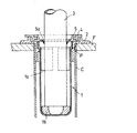
次に、本発明の他の実施形態について図2を参照して説明する。図2は、上記実施形態とは排水トラップ本体の構造が異なるが、他の構造は上記実施形態と同様の構成である。図2の実施形態では、排水トラップ本体1′が排水カップ2′と排水カップ2′に挿入されるストロー3′とから構成され、ストロー3′の中心軸が排水カップ2′の中心軸と略一致するように組み込まれている。排水カップ2′はその上部に越流部2a′が設けられている。排水カップ2′の底部2b′は、内部の中心に円錐状突起2cが設けられている。
Next, another embodiment of the present invention will be described with reference to FIG. FIG. 2 differs from the above embodiment in the structure of the drain trap body, but the other structure is the same as the above embodiment. In the embodiment of FIG. 2, the
ストロー3′を流下する排水は、円錐状突起2cを中心に分散されて排水カップ2′の内壁面に沿って流れて越流部2a′から排水管Cに流れ出る。排水は、排水トラップ本体1′の軸中心を流下して円錐状突起2cに到達して分散されて越流部2a′から排水管Cに排水されており、排水トラップ本体1′内での流水抵抗は極めて小さく、排水ポンプなどにより強制的に排水される場合であっても排水が排水トラップに送り込まれたとしても排水ホースに衝撃を与えることなく、排水トラップ内を流下して排水される。従って、上記実施形態と比較して、排水ホース8に加わる衝撃は殆ど無視できる程度となり、排水ホース8にホースジョイント6から押し出すような力が加わることがなく、排水ホース8がホースジョイント6から抜け落ちることがない。
The drainage flowing down the straw 3 'is dispersed around the
本発明の活用例としては、洗い場、浴室、洗面所、洗濯機、或いは各種キャビネット等の排水トラップとして利用することができ、殊にドラム式洗濯機の排水ホースが接続される排水トラップとして効果的である。 As an application example of the present invention, it can be used as a drain trap for a washing place, bathroom, washroom, washing machine, various cabinets, etc., and particularly effective as a drain trap to which a drain hose of a drum type washing machine is connected. It is.
1 排水トラップ本体
2 排水カップ
2a 越流部
2b 底部
3 ストロー
3a 湾曲部
4 排水トラップ受部
4a 環状突起部
4b ネジ
5パッキンホルダ
5a テーパ面
6 ホースジョイント
6a テーパー状フランジ部
6b 嵌入部
6c テーパ面
7 ホースバンド金具
8 排水ホース
8a 蛇腹状部
8b 先端部
F 床
P 開口部
C 排水管
DESCRIPTION OF
Claims (5)
残留排水により水封して臭気を遮断するための排水トラップ本体と、
該排水トラップ本体を支持する排水トラップ本体受部と、
該排水トラップ本体受部に接続されるホースジョイントと、
該ホースジョイントに設けたテーパー状フランジ部に係合し、該ホースジョイントを前記排水トラップ本体受部に接続するパッキンホルダーとからなり、
前記ホースジョイントの排水ホースの接続部に該排水ホースの蛇腹状部が嵌合する嵌入部が形成され、該ホースジョイントと該排水ホースとの接続部をホースバンド固定金具で緊縮して該ホースジョイントに該排水ホースを接続するようにしたことを特徴とする排水トラップ。 In the drain trap installed by inserting into the drain pipe that opens to the floor,
A drain trap body for sealing with residual waste water and blocking odor,
A drain trap body receiving part for supporting the drain trap body;
A hose joint connected to the drain trap body receiving part;
It consists of a packing holder that engages with a tapered flange provided on the hose joint and connects the hose joint to the drain trap body receiving part,
A fitting portion where the bellows-like portion of the drainage hose is fitted is formed in the drainage hose connection portion of the hose joint, and the connection portion between the hose joint and the drainage hose is tightened with a hose band fixing bracket. A drainage trap characterized in that the drainage hose is connected to the drainage hose.
Priority Applications (1)
| Application Number | Priority Date | Filing Date | Title |
|---|---|---|---|
| JP2005337030A JP2007138654A (en) | 2005-11-22 | 2005-11-22 | Drain trap |
Applications Claiming Priority (1)
| Application Number | Priority Date | Filing Date | Title |
|---|---|---|---|
| JP2005337030A JP2007138654A (en) | 2005-11-22 | 2005-11-22 | Drain trap |
Publications (1)
| Publication Number | Publication Date |
|---|---|
| JP2007138654A true JP2007138654A (en) | 2007-06-07 |
Family
ID=38201856
Family Applications (1)
| Application Number | Title | Priority Date | Filing Date |
|---|---|---|---|
| JP2005337030A Pending JP2007138654A (en) | 2005-11-22 | 2005-11-22 | Drain trap |
Country Status (1)
| Country | Link |
|---|---|
| JP (1) | JP2007138654A (en) |
Cited By (4)
| Publication number | Priority date | Publication date | Assignee | Title |
|---|---|---|---|---|
| GB2459915A (en) * | 2008-03-06 | 2009-11-18 | Mark David Marston | Removable inline waste water trap |
| CN102852208A (en) * | 2012-02-20 | 2013-01-02 | 王丹 | Side-draining stink-proof standard floor drain |
| JP2016089535A (en) * | 2014-11-07 | 2016-05-23 | ミヤコ株式会社 | Drain trap |
| JP2019187630A (en) * | 2018-04-20 | 2019-10-31 | 丸一株式会社 | Washing machine drain hose joint structure |
Citations (3)
| Publication number | Priority date | Publication date | Assignee | Title |
|---|---|---|---|---|
| JP2003306967A (en) * | 2002-04-15 | 2003-10-31 | Mitsubishi Plastics Ind Ltd | Drain trap |
| JP2003321860A (en) * | 2002-04-30 | 2003-11-14 | Techno Tec:Kk | Drain trap |
| JP2004332284A (en) * | 2003-05-02 | 2004-11-25 | Kakudai:Kk | Floor drain trap with ventilation function |
-
2005
- 2005-11-22 JP JP2005337030A patent/JP2007138654A/en active Pending
Patent Citations (3)
| Publication number | Priority date | Publication date | Assignee | Title |
|---|---|---|---|---|
| JP2003306967A (en) * | 2002-04-15 | 2003-10-31 | Mitsubishi Plastics Ind Ltd | Drain trap |
| JP2003321860A (en) * | 2002-04-30 | 2003-11-14 | Techno Tec:Kk | Drain trap |
| JP2004332284A (en) * | 2003-05-02 | 2004-11-25 | Kakudai:Kk | Floor drain trap with ventilation function |
Cited By (5)
| Publication number | Priority date | Publication date | Assignee | Title |
|---|---|---|---|---|
| GB2459915A (en) * | 2008-03-06 | 2009-11-18 | Mark David Marston | Removable inline waste water trap |
| GB2459915B (en) * | 2008-03-06 | 2013-01-30 | Mark David Marston | Removable access trap |
| CN102852208A (en) * | 2012-02-20 | 2013-01-02 | 王丹 | Side-draining stink-proof standard floor drain |
| JP2016089535A (en) * | 2014-11-07 | 2016-05-23 | ミヤコ株式会社 | Drain trap |
| JP2019187630A (en) * | 2018-04-20 | 2019-10-31 | 丸一株式会社 | Washing machine drain hose joint structure |
Similar Documents
| Publication | Publication Date | Title |
|---|---|---|
| GB2296309A (en) | Non-return device | |
| JP2007138654A (en) | Drain trap | |
| US6272699B1 (en) | Overflow drain insert | |
| JP2008025106A (en) | Drain trap | |
| JP4872867B2 (en) | Washing bowl drainage structure | |
| JP5651830B2 (en) | Connection structure between tank and drainage | |
| JP2004036114A (en) | Floor drain trap | |
| KR20030012778A (en) | draining traps | |
| KR100809742B1 (en) | A bad smell interception device for a water pipe | |
| JP5576027B2 (en) | Ventilation integrated fitting | |
| KR200465364Y1 (en) | Drainage trap assembly | |
| JP2012180656A (en) | Check valve | |
| JP2007023688A (en) | Drain trap | |
| KR101186776B1 (en) | The washstand drainage device which possessed a globe fixed a conduit pipe | |
| KR102536793B1 (en) | Drain trap assembly | |
| JP5200254B2 (en) | Connection structure | |
| JP2011074702A (en) | Remote-control type drain plug device | |
| KR20190105865A (en) | Pipe connecting device of a drain trap for a washhand stand | |
| JP2005253696A (en) | Water receiving tray | |
| JP2004332284A (en) | Floor drain trap with ventilation function | |
| JP3422766B2 (en) | Unit bath drain trap | |
| JP6335953B2 (en) | Drainage joint and drainage system using the same | |
| KR102047158B1 (en) | draining trap for washstand | |
| JP3130730U (en) | Drain pipe connection structure | |
| JP2017014781A (en) | Fixation structure of annular elastic body |
Legal Events
| Date | Code | Title | Description |
|---|---|---|---|
| A621 | Written request for application examination |
Free format text: JAPANESE INTERMEDIATE CODE: A621 Effective date: 20080704 |
|
| A977 | Report on retrieval |
Free format text: JAPANESE INTERMEDIATE CODE: A971007 Effective date: 20101112 |
|
| A131 | Notification of reasons for refusal |
Free format text: JAPANESE INTERMEDIATE CODE: A131 Effective date: 20101221 |
|
| A02 | Decision of refusal |
Free format text: JAPANESE INTERMEDIATE CODE: A02 Effective date: 20110426 |