JP5200254B2 - Connection structure - Google Patents
Connection structure Download PDFInfo
- Publication number
- JP5200254B2 JP5200254B2 JP2007248223A JP2007248223A JP5200254B2 JP 5200254 B2 JP5200254 B2 JP 5200254B2 JP 2007248223 A JP2007248223 A JP 2007248223A JP 2007248223 A JP2007248223 A JP 2007248223A JP 5200254 B2 JP5200254 B2 JP 5200254B2
- Authority
- JP
- Japan
- Prior art keywords
- tank body
- main body
- connection structure
- water
- cover body
- Prior art date
- Legal status (The legal status is an assumption and is not a legal conclusion. Google has not performed a legal analysis and makes no representation as to the accuracy of the status listed.)
- Active
Links
Images


Description
本発明は、槽体のオーバーフロー用流路や、排水流路に構成される取付口に接続される管体などの接続構造に関するものである。 The present invention relates to a connection structure such as an overflow channel of a tank body and a pipe connected to an attachment port formed in a drainage channel.
従来よく知られた接続構造としては、例えば図13に図示した接続構造がある。以下に図13に図示した接続構造の従来例を、図面を参照しつつ説明する。
図13の従来例の接続構造は、洗面ボウルなどの槽体に構成される、槽体内の溢れ水を排水管へ排水するオーバーフロー用流路に用いられるものである。
この従来例は、洗面ボウルである槽体と、取付口と、本体部と、止水パッキンと、目皿部材と、雄ねじと、オーバーフロー用流路と、排水流路と、から構成される。
槽体は、内部に排水を注水/排水する箱体であって、底面に排水を槽体外へ排出するための排水口を開口して構成される。
取付口は、槽体上端に構成される、槽体内の溢れ水を槽体外へ排出するための開口である。
本体部は、槽体裏面の取付口に取り付けられる、断面視略L字状のエルボであって、取付口側の内部に、雌ねじ受け部を構成する。
止水パッキンは、槽体の取付口と本体部に介在される弾性部材であって、槽体内の排水が外部に漏水させないために備えられる部材である。
目皿部材は、取付口に取り付けられる格子状の部材であって、槽体内の排水中にゴミや髪の毛が混入している場合に排水流路側へ排出させないためのガード部材であり、中央には貫通孔が構成される。
雄ねじは、槽体側から目皿部材の貫通孔に螺合させ、槽体の裏側の取付口に取り付けられた本体部の雌ねじ受け部に螺合させる。そうすると、雄ねじが目皿部材と、槽体の取付口と、止水パッキンと、本体部を挟持するように締め付けられて、取付口裏面に本体部を取り付けることが出来る。
オーバーフロー用流路は、槽体内の排水が、槽体外へと溢れてこぼれ落ちることを防ぐために構成された流路であって、槽体の取付口から本体部を介して、最終的には排水トラップを介して下水管へと排出する流路である。
排水流路は、槽体の排水口から下水管までの流路であって、途中位置に下水管からの臭気や害虫の室内側への逆流を防ぐ内部に封水を有した排水トラップを構成して成る。
As a well-known connection structure, for example, there is a connection structure shown in FIG. A conventional example of the connection structure shown in FIG. 13 will be described below with reference to the drawings.
The connection structure of the conventional example in FIG. 13 is used for an overflow channel configured to be a tank body such as a wash bowl and draining overflow water in the tank body to a drain pipe.
This conventional example is composed of a tank body that is a wash bowl, an attachment port, a main body, a water stop packing, a countersink member, a male screw, an overflow channel, and a drain channel.
The tank body is a box body that pours / drains waste water therein, and is configured by opening a drain outlet for discharging the waste water to the outside of the tank body on the bottom surface.
The attachment opening is an opening for discharging overflow water in the tank body to the outside of the tank body, which is configured at the upper end of the tank body.
The main body is an elbow having a substantially L-shaped cross-sectional view that is attached to the attachment port on the rear surface of the tank body, and constitutes a female screw receiving portion inside the attachment port.
The water-stop packing is an elastic member interposed between the attachment port and the main body of the tank body, and is a member provided to prevent the drainage in the tank body from leaking to the outside.
The eye plate member is a lattice-like member that is attached to the attachment port, and is a guard member for preventing discharge to the drainage channel side when dust or hair is mixed in the drainage in the tank body. A through hole is formed.
The male screw is screwed into the through hole of the eye plate member from the tank body side, and is screwed into the female screw receiving part of the main body part attached to the attachment port on the back side of the tank body. Then, the male screw is tightened so as to sandwich the eye plate member, the mounting opening of the tank body, the water blocking packing, and the main body, and the main body can be attached to the back surface of the mounting opening.
The overflow channel is a channel configured to prevent the drainage of the tank body from overflowing and spilling out of the tank body, and finally the drainage from the attachment port of the tank body through the main body. It is a flow path which discharges to a sewer pipe through a trap.
The drainage channel is a channel from the drainage port of the tank body to the sewer pipe, and constitutes a drainage trap with sealed water inside to prevent backflow of odors and pests from the sewer pipe to the indoor side in the middle position It consists of
また、別の従来例として、図14に図示した接続構造がある。以下に図14に図示した接続構造の従来例を、図面を参照しつつ説明する。
図14の従来例の接続構造は、洗面ボウルなどの槽体に構成される、槽体内の溢れ水を排水管へ排水するオーバーフロー用流路に用いられるものである。
この従来例は、洗面ボウルである槽体と、取付口と、本体部と、止水パッキンと、取付ガイドと、雄ねじと、オーバーフロー用流路と、排水流路と、から構成される。
槽体は、内部に排水を注水/排水する箱体であって、底面に排水を槽体外へ排出するための排水口を開口して構成される。
取付口は、槽体上端に構成される、槽体内の溢れ水を槽体外へ排出するための開口である。
本体部は、槽体裏面の取付口に取り付けられる、断面視略L字状のエルボであって、外側面に、雌ねじ受け部を構成する。
止水パッキンは、槽体の取付口と本体部に介在される弾性部材であって、槽体内の排水が外部に漏水させないために備えられる部材である。
取付ガイドは、槽体裏面の取付口に取り付けられる部材であって、本従来例では溶接などにて槽体裏面に取付られる。また、取付ガイドは、貫通孔が構成されて成る。
雄ねじは、槽体裏側から取付ガイドの貫通孔に貫通させて、取付ガイドと槽体の取付口間に配置された本体部の雌ねじ受け部に螺合する部材である。また、槽体裏側から取付ガイドの貫通孔に雄ねじを挿入し、本体の雌ねじ受け部に螺合させる。そうすると、本体部に螺合された雄ねじにより、槽体の取付口周縁側へ止水パッキンと本体部が押圧固定されて取り付けられることが出来る。
オーバーフロー用流路は、槽体内の排水が、槽体外へと溢れてこぼれ落ちることを防ぐために構成された流路であって、槽体の取付口から本体部を介して、最終的には排水トラップを介して下水管へと排出する流路である。
排水流路は、槽体の排水口から下水管までの流路であって、途中位置に下水管からの臭気や害虫の室内側への逆流を防ぐ内部に封水を有した排水トラップを構成して成る。
As another conventional example, there is a connection structure shown in FIG. Hereinafter, a conventional example of the connection structure illustrated in FIG. 14 will be described with reference to the drawings.
The connection structure of the conventional example of FIG. 14 is used for an overflow channel configured to be a tank body such as a wash bowl and draining overflow water in the tank body to a drain pipe.
This conventional example is composed of a tank body that is a wash bowl, an attachment port, a main body, a water stop packing, an attachment guide, a male screw, an overflow passage, and a drain passage.
The tank body is a box body that pours / drains waste water therein, and is configured by opening a drain outlet for discharging the waste water to the outside of the tank body on the bottom surface.
The attachment opening is an opening for discharging overflow water in the tank body to the outside of the tank body, which is configured at the upper end of the tank body.
The main body is an elbow having a substantially L-shaped cross-sectional view that is attached to the attachment port on the rear surface of the tank body, and constitutes a female screw receiving portion on the outer surface.
The water-stop packing is an elastic member interposed between the attachment port and the main body of the tank body, and is a member provided to prevent the drainage in the tank body from leaking to the outside.
The attachment guide is a member attached to the attachment port on the rear surface of the tank body, and is attached to the rear surface of the tank body by welding or the like in this conventional example. Further, the mounting guide has a through hole.
The male screw is a member that passes through the through hole of the mounting guide from the rear side of the tank body and is screwed into the female screw receiving portion of the main body portion disposed between the mounting guide and the mounting port of the tank body. Further, a male screw is inserted into the through hole of the mounting guide from the rear side of the tank body, and screwed into the female screw receiving portion of the main body. If it does so, a water stop packing and a main-body part can be fixed by being fixed to the attachment port peripheral side of a tank body by the external thread screwed together by the main-body part.
The overflow channel is a channel configured to prevent the drainage of the tank body from overflowing and spilling out of the tank body, and finally the drainage from the attachment port of the tank body through the main body. It is a flow path which discharges to a sewer pipe through a trap.
The drainage channel is a channel from the drainage port of the tank body to the sewer pipe, and constitutes a drainage trap with sealed water inside to prevent backflow of odors and pests from the sewer pipe to the indoor side in the middle position It consists of
また、別の従来例として、図15に図示した接続構造がある。以下に図15に図示した接続構造の従来例を、図面を参照しつつ説明する。
図15の従来例の接続構造は、洗面ボウルなどの槽体に構成される、槽体内の溢れ水を排水管へ排水するオーバーフロー用流路に用いられるものである。
この従来例は、洗面ボウルである槽体と、取付口と、オーバーフローフランジと、本体部と、止水パッキンと、オーバーフロー用流路と、排水流路と、から構成される。
槽体は、内部に排水を注水/排水する箱体であって、底面に排水を槽体外へ排出するための排水口を開口して構成される。
取付口は、平面視円形であって、槽体上端に構成される、槽体内の溢れ水を槽体外へ排出するための開口である。
オーバーフローフランジは、円筒上の部材であって、端部に外側方向に突出して構成されるフランジ部を構成し、他端外周には雄ねじが刻設されている。
本体部は、槽体裏面の取付口に取り付けられる、断面視略L字状のエルボで、取付口に接続される側の端部が円筒状で、内周面に雌ねじを刻設してオーバーフローフランジの雄ねじと接続されて成る。
止水パッキンは、槽体の取付口と本体部、オーバーフローフランジに介在される弾性部材であって、槽体内の排水が外部に漏水させないために備えられる部材である。
これらの部材の接続方法としては、オーバーフローフランジのフランジ部を槽体の取付口に挿入させて取付口周縁にフランジ部を係止させて、槽体裏面からオーバーフランジと取付口周縁部に止水パッキンを介在させて、本体部の雌ねじを、オーバーフローフランジの雄ねじに螺合させる。このように、槽体の取付口を介在して、オーバーフローフランジのフランジ部と本体部の雄ねじ・雌ねじで締め付けることで、槽体の取付口周縁部をフランジ部と本体部のそれぞれで挟持するように接続することが出来る。
オーバーフロー用流路は、槽体内の排水が、槽体外へと溢れてこぼれ落ちることを防ぐために構成された流路であって、槽体の取付口から本体部を介して、最終的には排水トラップを介して下水管へと排出する流路である。
排水流路は、槽体の排水口から下水管までの流路であって、途中位置に下水管からの臭気や害虫の室内側への逆流を防ぐ内部に封水を有した排水トラップを構成して成る。
As another conventional example, there is a connection structure shown in FIG. A conventional example of the connection structure shown in FIG. 15 will be described below with reference to the drawings.
The connection structure of the conventional example of FIG. 15 is used for an overflow channel configured to be a tank body such as a wash bowl and draining overflow water in the tank body to a drain pipe.
This conventional example is composed of a tank body that is a wash bowl, an attachment port, an overflow flange, a main body, a water stop packing, an overflow channel, and a drain channel.
The tank body is a box body that pours / drains waste water therein, and is configured by opening a drain outlet for discharging the waste water to the outside of the tank body on the bottom surface.
The attachment port is a circular shape in plan view, and is an opening for discharging overflow water in the tank body to the outside of the tank body, which is configured at the upper end of the tank body.
The overflow flange is a member on a cylinder and forms a flange portion that protrudes outward at an end portion, and a male screw is engraved on the outer periphery of the other end.
The main body is an elbow with a substantially L-shaped cross-sectional view that is attached to the attachment port on the rear surface of the tank body. The end on the side connected to the attachment port is cylindrical, and an internal thread is engraved on the inner peripheral surface to overflow. It is connected to the external thread of the flange.
The water stop packing is an elastic member interposed between the mounting opening of the tank body, the main body, and the overflow flange, and is a member provided to prevent the drainage in the tank body from leaking to the outside.
The connecting method of these members is to insert the flange part of the overflow flange into the mounting port of the tank body, lock the flange part at the periphery of the mounting port, and stop the water from the rear surface of the tank body to the over flange and the peripheral part of the mounting port. With the packing interposed, the internal thread of the main body is screwed into the external thread of the overflow flange. In this way, the peripheral part of the attachment port of the tank body is sandwiched between the flange part and the main body part by tightening the flange part of the overflow flange and the male screw / female screw of the main body part through the attachment port of the tank body. Can be connected to.
The overflow channel is a channel configured to prevent the drainage of the tank body from overflowing and spilling out of the tank body, and finally the drainage from the attachment port of the tank body through the main body. It is a flow path which discharges to a sewer pipe through a trap.
The drainage channel is a channel from the drainage port of the tank body to the sewer pipe, and constitutes a drainage trap with sealed water inside to prevent backflow of odors and pests from the sewer pipe to the indoor side in the middle position It consists of
このような従来例の接続構造においては、以下のような排水の流れとなる。
槽体内の排水が上昇すると、槽体上端付近に構成された取付口から排水が槽体裏面に取り付けられた本体部内へ流入する。本体部内の排水は、オーバーフロー用流路を介して排水流路へと排出され、排水トラップを介して最終的には下水管へと排出される。
In such a connection structure of the conventional example, the flow of drainage is as follows.
When the drainage in the tank rises, the drainage flows into the main body attached to the rear surface of the tank body from an attachment port formed near the upper end of the tank body. The drainage in the main body is discharged to the drainage channel via the overflow channel, and finally to the sewer pipe via the drain trap.
また、別の従来例として、図16に図示した接続構造がある。以下に図16に図示した接続構造の従来例を、図面を参照しつつ説明する。
図16の従来例の接続構造は、台所などの槽体に構成される、排水口と排水管流路に用いられるものである。
この従来例は、流し台としての槽体と、排水口としての取付口と、本体部と、止水パッキンと、ナット部材と、排水流路と、から構成される。
槽体は、内部に排水を注水/排水する箱体である。
取付口は、槽体底面に開口された開口であって、槽体内の排水を槽体外へ排出するための開口である。
本体部は、槽体の取付口裏側に取り付けられる機器であって、本従来例では、上面視円形状であって、内部に封水を備えた下水からの害虫や異臭を室内側へ逆流させないための排水トラップを備える。また、本体上端部には外側方向に向かって突出して構成されるフランジ部を備える。そして、本体上端部外周には雄ねじを刻設してなる。また、本体部下端は後述する排水流路により最終的には下水管へ接続される。
止水パッキンは、槽体の取付口と本体部に介在される弾性部材であって、槽体内の排水が外部に漏水させないために備えられる部材である。
ナット部材は、環状部材であって、上端に外側方向に突出する鍔部を構成し、内周面には雌ねじを刻設してなる。
取付方としては、槽体の表面側の取付口周縁に止水パッキンを載置し、槽体の取付口の上方から、本体を取付口に挿入し、本体のフランジ部を取付口に係止させる。その後、槽体の裏面からナット部材を挿入し、本体部の外周に構成された雄ねじにナット部材の雌ねじを螺合させ、槽体の取付口周縁を挟持するようにして取り付けることが出来る。
排水流路は、取付口に接続された本体から接続された流路であって、最終的には下水管へと接続される。また、槽体内の排水を最終的には下水管へと排出するための管体である。
As another conventional example, there is a connection structure shown in FIG. A conventional example of the connection structure shown in FIG. 16 will be described below with reference to the drawings.
The connection structure of the conventional example of FIG. 16 is used for a drain outlet and a drain pipe flow path configured in a tank body such as a kitchen.
This conventional example includes a tank body as a sink, an attachment port as a drainage port, a main body, a water stop packing, a nut member, and a drainage channel.
The tank body is a box body that pours / drains wastewater inside.
The attachment port is an opening that is opened on the bottom surface of the tank body, and is an opening for discharging the waste water in the tank body to the outside of the tank body.
The main body is a device attached to the back side of the mounting opening of the tank body, and in this conventional example, is circular when viewed from above, and does not allow pests and off-flavors from sewage with sealed water inside to flow backward into the room. A drain trap is provided. Further, the upper end portion of the main body is provided with a flange portion configured to protrude outward. A male screw is formed on the outer periphery of the upper end of the main body. Further, the lower end of the main body is finally connected to the sewer pipe by a drainage channel described later.
The water-stop packing is an elastic member interposed between the attachment port and the main body of the tank body, and is a member provided to prevent the drainage in the tank body from leaking to the outside.
The nut member is an annular member, and forms a flange portion protruding outward at the upper end, and has an internal thread formed on the inner peripheral surface.
As for the mounting method, place a waterproof seal on the periphery of the mounting port on the surface side of the tank body, insert the main body into the mounting port from above the mounting port of the tank body, and lock the flange part of the main body to the mounting port Let Thereafter, the nut member can be inserted from the back surface of the tank body, and the female screw of the nut member can be screwed into the male screw formed on the outer periphery of the main body, so that the peripheral edge of the mounting opening of the tank body can be clamped.
The drainage channel is a channel connected from the main body connected to the attachment port, and is finally connected to the sewer pipe. Moreover, it is a pipe body for discharging the waste water in the tank finally to the sewer pipe.
また、別の従来例として、図17に図示した接続構造がある。以下に図17に図示した接続構造の従来例を、図面を参照しつつ説明する。
図17の従来例の接続構造は、台所や洗面台などの槽体に構成される、排水口と排水管流路に用いられるものである。
この従来例は、洗面台としての槽体と、排水口としての取付口と、本体部と、止水パッキンと、雄ねじと、排水流路と、から構成される。
槽体は、内部に排水を注水/排水する箱体である。
取付口は、槽体底面に開口された開口であって、槽体内の排水を槽体外へ排出するための開口である。また、槽体裏面の取付口周縁には、雌ねじが複数箇所開口構成されて成る。
本体部は、槽体の取付口裏側に取り付けられる機器であって、本従来例では、上面視円形状であって、本体部上端部には外側方向に向かって突出して構成されるフランジ部を備えてなる。また、本体部下端は後述する排水流路により最終的には下水管へ接続される。また、フランジ部には貫通孔を複数箇所構成して成る。
止水パッキンは、槽体の取付口と本体部に介在される弾性部材であって、槽体内の排水が外部に漏水させないために備えられる部材である。
雄ねじは、槽体裏面から本体部のフランジ部の貫通孔を介して槽体の取付口裏面側の雌ねじと螺合するねじである。
取付方としては、槽体の裏面側の取付口周縁に止水パッキンをセットし、槽体の取付口の裏側から、本体を取付口周縁に当接させ、その後、槽体の裏面から本体部のフランジ部貫通孔に雄ねじを挿入し、槽体の取付口の雌ねじに螺合させて、槽体の取付口に本体部を取り付けることが出来る。
排水流路は、取付口に接続された本体から接続された流路であって、最終的には下水管へと接続される。また、槽体内の排水を最終的には下水管へと排出するための管体である。
As another conventional example, there is a connection structure shown in FIG. A conventional example of the connection structure shown in FIG. 17 will be described below with reference to the drawings.
The connection structure of the conventional example of FIG. 17 is used for a drain outlet and a drain pipe flow path which are configured in a tank body such as a kitchen or a washstand.
This conventional example is composed of a tank body as a wash basin, an attachment port as a drainage port, a main body, a water stop packing, a male screw, and a drainage channel.
The tank body is a box body that pours / drains wastewater inside.
The attachment port is an opening that is opened on the bottom surface of the tank body, and is an opening for discharging the waste water in the tank body to the outside of the tank body. Further, a plurality of female screws are opened at the periphery of the mounting port on the rear surface of the tank body.
The main body part is a device attached to the back side of the mounting opening of the tank body, and in this conventional example, it is circular when viewed from above, and the upper end part of the main body part has a flange portion configured to protrude outward. Prepare. Further, the lower end of the main body is finally connected to the sewer pipe by a drainage channel described later. Further, the flange portion is formed with a plurality of through holes.
The water-stop packing is an elastic member interposed between the attachment port and the main body of the tank body, and is a member provided to prevent the drainage in the tank body from leaking to the outside.
The male screw is a screw that engages with the female screw on the rear surface side of the attachment port of the tank body from the rear surface of the tank body through the through hole of the flange portion of the main body.
As a mounting method, set a waterproof seal on the periphery of the mounting port on the back side of the tank body, and from the back side of the mounting port of the tank body, abut the main body against the periphery of the mounting port. The body portion can be attached to the attachment port of the tank body by inserting a male screw into the through hole of the flange portion and screwing it into the female screw of the attachment port of the tank body.
The drainage channel is a channel connected from the main body connected to the attachment port, and is finally connected to the sewer pipe. Moreover, it is a pipe body for discharging the waste water in the tank finally to the sewer pipe.
このような従来例の接続構造においては、以下のような排水の流れとなる。
槽体内に排水が発生すると、槽体底面に開口された取付口から排水が槽体裏面に取り付けられた本体部内へ流入する。本体部内の排水は、排水流路へと排出され、排水トラップを介して最終的には下水管へと排出される。
In such a connection structure of the conventional example, the flow of drainage is as follows.
When drainage is generated in the tank body, the drainage flows into the main body attached to the rear surface of the tank body from an attachment port opened on the bottom surface of the tank body. The drainage in the main body is discharged to the drainage channel and finally discharged to the sewer pipe through the drainage trap.
従来例のような接続構造は、以下のような問題点があった。
図13の従来例では、槽体の表面側から向かって雄ねじを目皿部材の貫通孔に挿通させて、本体部の雌ねじ受け部に螺合させるので、槽体の表面側から雄ねじの頭部分が露出してしまい、外観上意匠性が非常に悪かった。
また、図14の従来例では、取付ガイドをわざわざ槽体の裏面に溶着せねばならないので、取付作業が非常に手間であった。
また、図15の従来例では、雄ねじを使用しないことや、取付ガイドのようなものを槽体裏面にわざわざ取り付けないでもよいのでメリットはあるが、オーバーフローフランジと本体部の取付をねじ螺合による接続としているため、オーバーフローフランジ及び本体部を円形状にせねばならないので、槽体の取付口の形状の選択の幅が狭く、使用者によっては意匠性が非常に悪いと感じられる場合もあった。
また、図16の従来例では、取付口と本体部の取付をねじ螺合による接続としているため、取付口及び本体部、ナット部材を円形状にせねばならないので、槽体の取付口の形状の選択の幅が狭く、使用者によっては意匠性が非常に悪いと感じられる場合もあった。
また、図17の従来例では、取付口と本体部の取付を、槽体裏面から雄ねじと雌ねじによるねじ接続としているため、雄ねじを槽体の裏面に直接的に接続せねば成らず、槽体の裏面に雌ねじを刻設することが必要であった。このような作業は非常に手間である上、槽体に直接的に雌ねじを刻設するので、槽体が金属の薄板状の素材であったり、大理石などの脆い素材であった場合には雌ねじが刻設できないので、そういった素材の槽体には取り付けることは出来なかった。
The connection structure as in the conventional example has the following problems.
In the conventional example of FIG. 13, the male screw is inserted into the through hole of the countersink member from the surface side of the tank body and screwed into the female screw receiving portion of the main body portion. Was exposed, and the design was very poor in appearance.
Further, in the conventional example shown in FIG. 14, the mounting guide has to be welded to the back surface of the tank body, so that the mounting work is very troublesome.
Further, in the conventional example of FIG. 15, there is a merit because it is not necessary to use a male screw or to attach an attachment guide or the like to the rear surface of the tank body. Since it is connected, the overflow flange and the main body must be circular, so the range of selection of the shape of the mounting opening of the tank body is narrow, and some users may feel that the design is very poor.
In addition, in the conventional example of FIG. 16, since the attachment port and the main body are attached by screw threading, the attachment port, the main body, and the nut member must be circular. The range of selection was narrow, and some users felt that the design was very poor.
Moreover, in the conventional example of FIG. 17, since the attachment port and the main body portion are attached by screw connection with a male screw and a female screw from the rear surface of the tank body, the male screw must be directly connected to the rear surface of the tank body. It was necessary to engrave an internal thread on the back side of the. Such work is very troublesome and the internal thread is directly engraved in the tank body, so if the tank body is a thin metal plate material or a brittle material such as marble, the internal thread Could not be engraved, so it could not be attached to a tank of such material.
従って、本発明の接続構造は、以下の課題を解決するために発明された。
1.使用者が外観視できる槽体の表面側の意匠性が良い接続構造。
2.取付作業が簡単である接続構造。
3.円形以外の取付口でも接続することが出来る接続構造。
4.槽体に雌ねじを刻設することなく接続することが出来る接続構造。
Accordingly, the connection structure of the present invention was invented to solve the following problems.
1. A connection structure with good design on the surface side of the tank body that the user can visually see.
2. Connection structure for easy installation.
3. Connection structure that can be connected with non-circular mounting ports.
4). Connection structure that can be connected without engraving female threads in the tank.
請求項1の接続構造は、機器に開口された取付口1と、取付口1内に挿入される筒部2と、端部に外側方向に突出して構成され、前記取付口1周縁に係止されるフランジ部3と、筒部2に構成された雌ねじ部4と、から構成されるカバー体5と、前記カバー体5の筒部2をその内部に挿入して受け入れ、前記フランジ部3とで前記取付口1を狭持する受け部9と、貫通して構成される筒状の貫通孔10と、を構成した断面視L字状且つエルボ体の本体11と、前記カバー体5の筒部2外周と、本体11の受け部9に水密的に当接して介在する第2止水パッキン7と、前記本体11の貫通孔10とカバー体5の雌ねじ部4の両者を接合する雄ねじ体12と、から構成されることを特徴とする接続構造である。
The connection structure according to
請求項2の接続構造は、機器に開口された取付口1と、取付口1内に挿入される筒部2と、端部に外側方向に突出して構成され、前記取付口1周縁に係止されるフランジ部3と、筒部2に構成された雄ねじと、から構成されるカバー体5と、前記カバー体5の筒部2をその内部に挿入して受け入れ、前記フランジ部3とで前記取付口1を狭持する受け部9と、貫通して構成される筒状の貫通孔10と、を構成した断面視L字状且つエルボ体の本体11と、前記カバー体5の筒部2外周と、本体11の受け部9に水密的に当接して介在する第2止水パッキン7と、前記本体11の貫通孔10とカバー体5の雄ねじの両者を接合する雌ねじと、から構成されることを特徴とする接続構造である。
The connection structure according to
請求項3の接続構造は、前記フランジ部3と取付口1周縁の間に配置される、弾性部材から構成された第1止水パッキン6を備えたことを特徴とする前記請求項1又は請求項2のいずれか一つに記載の接続構造である。
The connection structure according to
請求項4の接続構造は、前記第1止水パッキン6の外周面に、凸部8を構成したことを特徴とする請求項3に記載の接続構造である。
The connection structure according to
請求項5の接続構造は、前記第2止水パッキン7の外周面に、凸部8を構成したことを特徴とする請求項1乃至請求項4のいずれか一つに記載の接続構造である。
The connection structure according to
請求項6の接続構造は、前記取付口1が、槽体のオーバーフロー用流路15の接続構造であることを特徴とする請求項1乃至請求項5のいずれか一つに記載の接続構造である。
The connection structure according to
本発明の接続構造は、以下の効果を奏する。
請求項1又は請求項3乃至請求項6に記載の本発明は、機器に開口された取付口1と、取付口1内に挿入される筒部2と、端部に外側方向に突出して構成され、前記取付口1周縁に係止されるフランジ部3と、筒部2に構成された雌ねじ部4と、から構成されるカバー体5と、フランジ部3と取付口1周縁の間に配置される、弾性部材から構成された第1止水パッキン6と、前記カバー体5を受け入れる受け部9と、貫通して構成される貫通孔10と、を構成した本体11と、前記カバー体5と本体11に介在して備えられる第2止水パッキン7と、前記本体11の貫通孔10とカバー体5の雌ねじ部4の両者を接合する雄ねじ体12と、から構成したことから、雄ねじなどが使用者から目視できる槽体13の外観上に露出しないので、非常に意匠性がよい。また、本体11とカバー体5の接続を、雄ねじ体12による接続とし、本体11外周に雄ねじを刻設してナットなどの雌ねじにより締め付けて槽体13と取り付ける方法としていないので、丸形以外の形状でも接続することが出来る。
また、雄ねじ体12を槽体13の裏面から螺合させるだけなので、取付作業も非常に簡単に行うことが出来る。また、雄ねじ体12をカバー体5の雌ねじ部44に螺合させるようにしたから、槽体13に直接的に雌ねじ部44を刻設することなく取り付けることが出来るので、どのような素材の槽体13であっても接続することが出来る。
請求項2乃至請求項6に記載の本発明は、雄ねじなどが使用者から目視できる槽体13の外観上に露出しないので、非常に意匠性がよい。また、本体11とカバー体5の接続を、カバー体5の雄ねじと雌ねじによる接続とし、本体11外周に雄ねじを刻設してナットなどの雌ねじにより締め付けて槽体13と取り付ける方法としていないので、丸形以外の形状でも接続することが出来る。また、雌ねじを槽体13の裏面から螺合させるだけなので、取付作業も非常に簡単に行うことが出来る。また、雌ねじをカバー体5の雄ねじに螺合させるようにしたから、槽体13に直接的に雌ねじ部44を刻設することなく取り付けることが出来るので、どのような素材の槽体13であっても接続することが出来る。
請求項4に記載の本発明は、第1止水パッキン6の外周面に、凸部8を構成したことから、より止水能力が向上するようになった。
請求項5に記載の本発明は、第2止水パッキン7の外周面に、凸部8を構成したことから、より止水能力が向上するようになった。
請求項6に記載の本発明は、槽体13のオーバーフロー用流路15の接続構造としたから、前記した請求項1乃至請求項6における効果を槽体13のオーバーフロー用流路15の接続構造において奏することができる。
The connection structure of the present invention has the following effects.
The present invention according to
Further, since the
The present invention according to
Since the
Since the
Since the present invention described in
以下に本発明の第1実施例を、図面を参照しつつ説明する。
本発明の接続構造は、図1乃至図10に図示した接続構造である。以下に接続構造の実施例を、図面を参照しつつ説明する。
図1乃至図10に図示した本実施例の接続構造は、洗面ボウルなどの槽体13に構成される、槽体13内の溢れ水を排水管へ排水するオーバーフロー用流路15に用いられるものである。
本実施例は、洗面ボウルである槽体13と、取付口1と、カバー体5と、第1止水パッキン6と、本体11と、第2止水パッキン7と、雄ねじ体12と、から構成される。
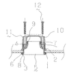
槽体13は、内部に排水を注水/排水する箱体であって、底面に排水を槽体13外へ排出するための排水口14を開口して構成される。
取付口1は、槽体13上端に構成される、槽体13内の溢れ水を槽体13外へ排出するための開口である。尚、本実施例においては取付口1は楕円形状に開口されて成る。
カバー体5は、図8に示すように、開口形状が楕円形状の円筒から成る筒部2と、筒部2の一方の端部に、外側方向に向かって突出して構成されるフランジ部3と、筒部2に一部肉厚部分を構成し、その肉厚部分に開口・刻設して構成された雌ねじ部4を複数箇所構成して成る。また、カバー体5の筒部2には、後述する第2止水パッキン7の取付時の位置合わせ用の凹部17を構成して成る。
第1止水パッキン6は、図9に示すように、環状であって、外周の上下面の周縁に沿って複数の凸部8を構成して成る。また、ゴムなどの弾性部材から成る止水部材であって、前記カバー体5のフランジ部3裏面にセットされて、槽体13内の排水が取付口1の裏面に漏水することを防止する部材である。
本体11は、図7に示すように、断面視L字状のエルボ体であって、前記カバー体5の筒部2をその内部に受け入れる受け部9と、カバー体5が受け部9内に収納された際にカバー体5の雌ねじ部4と合致する箇所に開口された貫通孔10とを構成して成る。
第2止水パッキン7は、図10に示すように、環状であって、ゴムなどの弾性部材から構成され、外周の周縁に沿って複数の凸部8を構成して成る。また、軸方向上下面には、カバー体5との位置合わせ用のリブ18を備える。また、前記カバー体5の筒部2外周に取り付けられ、カバー体5の位置合わせ用凹部17に第2止水パッキン7のリブ18を合致させて位置あわせをして取り付ける。接続状態の時、本体11の受け部9内周面と水密的に接するように配置され、カバー体5及び本体11内に流入した排水が、槽体13の裏面側であるカバー体5と本体11の間から漏水することを防止する部材である。
雄ねじ体12は、ボルトなどの雄ねじであって、本実施例ではカバー体5に構成された雌ねじ部4に、本体11に構成された貫通孔10を介して螺合する。
オーバーフロー用流路15は、槽体13内の排水が、槽体13外へと溢れてこぼれ落ちることを防ぐために構成された流路であって、槽体13の取付口1から本体11を介して、最終的には排水トラップを介して下水管へと排出する流路である。
排水流路16は、槽体13の排水口14から下水管までの流路であって、途中位置に下水管からの臭気や害虫の室内側への逆流を防ぐ内部に封水を有した排水トラップを構成して成る。
A first embodiment of the present invention will be described below with reference to the drawings.
The connection structure of the present invention is the connection structure shown in FIGS. Embodiments of the connection structure will be described below with reference to the drawings.
The connection structure of the present embodiment shown in FIGS. 1 to 10 is used for an
In this embodiment, the
The
The
As shown in FIG. 8, the
As shown in FIG. 9, the first water blocking packing 6 is annular and includes a plurality of
As shown in FIG. 7, the main body 11 is an elbow body having an L-shape in cross-section, and a receiving
As shown in FIG. 10, the second water-
The
The
The
このように構成された接続構造は以下のように接続される。
図4に示すように、カバー体5の筒部2に第1止水パッキン6を配置させ、槽体13の取付口1に、槽体13の表面側からカバー体5の筒部2を挿入し、カバー体5のフランジ部3を、第1止水パッキン6を介して取付口1周縁に係止させる。
そして、図5に示すように、槽体13の裏面からカバー体5の位置合わせ用凹部17の切り溝に合致するように第2止水パッキン7の位置合わせ用リブ18を合致させて位置あわせを行うことでカバー体5の筒部2外周に第2止水パッキン7を配置させる。そして槽体13の裏面から飛び出しているカバー体5の筒部2に、本体11の受け部9を挿入する。このとき、第2止水パッキン7の凸部8は本体11の受け部9に水密的に当接させるように、また、本体11の貫通孔10はカバー体5の雌ねじ部4に合致するようにそれぞれ挿入する。
そして、図6に示すように、槽体13の裏面から、雄ねじ体12を、本体11の貫通孔10に挿通させ、貫通孔10に合致するように配置されたカバー体5の雌ねじ部4に螺合させる。そうすると、本体11は雄ねじ体12とカバー体5に挟まれるように雄ねじ体12の締め付けによりカバー体5と接続される。また、同時に雄ねじ体12の締め付けにより、槽体13の取付口1はカバー体5のフランジ部3と本体11の受け部9に挟持されるように接続される。そして、槽体13の取付口1にカバー体5・本体11を接続することが出来る。このとき、カバー体5のフランジ部3と槽体13の取付口1周縁は第1止水パッキン6により水密化されているので漏水することがなく、また、カバー体5と本体11の間には第2止水パッキン7が介在して水密化しているので漏水することがない。また、カバー体5に第2止水パッキン7との位置合わせ用の凹部17を構成し、第2止水パッキン7にもカバー体5との位置あわせ用リブ18を構成したことから、カバー体5と第2止水パッキン7のセット(配置)が簡単となる上、誤配置もなくすことができる。
このように接続することで、槽体13に簡単に接続することが出来るし、槽体13の取付口1に直接的に雌ねじを刻設することもなく、槽体13の表面側から雄ねじ体12の頭が露出するようなこともなく、また、取付口1の形状を丸形以外の形状とすることができる。また、第2止水パッキン7の外周に凸部8を構成したからより水密性が向上することとなった。
また、本体11の下流には、排水管を接続し、最終的には排水流路16と接続するように配管される。
尚、ここでいう槽体13の表面側とは、使用者が通常使用時に外観視できる槽体13の部位であり、槽体13の裏面側は通常使用時に使用者が外観視できない槽体13の部位を指す。
The connection structure configured in this way is connected as follows.
As shown in FIG. 4, the first water-stopping
Then, as shown in FIG. 5, the
Then, as shown in FIG. 6, from the back surface of the
By connecting in this way, it can be easily connected to the
Further, a drain pipe is connected downstream of the main body 11, and finally piped so as to connect to the
In addition, the surface side of the
このような実施例の接続構造においては、以下のような排水の流れとなる。
槽体13内の排水が上昇すると、槽体13上端付近に構成された取付口1から排水が、カバー体5を介して槽体13裏面に取り付けられた本体11内へ流入する。本体11内の排水は、オーバーフロー用流路15を介して排水流路16へと排出され、排水トラップを介して最終的には下水管へと排出される。
In the connection structure of such an embodiment, the flow of drainage is as follows.
When the drainage in the
また、第2実施例として、図11乃至図12に図示した接続構造がある。以下に図示した接続構造の従来例を、図面を参照しつつ説明する。
図11乃至図12に図示した本実施例の接続構造は、台所や洗面ボウルなどの槽体13に構成される、槽体13内の排水を排水管、最終的には下水管へと排水する排水流路16に用いられるものである。
本実施例は、洗面ボウルである槽体13と、排水口14としての取付口1と、カバー体5と、第1止水パッキン6と、本体11と、第2止水パッキン7と、雄ねじ体12と、から構成される。
槽体13は、内部に排水を注水/排水する箱体であって、底面に排水を槽体13外へ排出するための排水口14を取付口1として開口して構成される。
取付口1は、槽体13底面に構成される、槽体13内の排水を槽体13外へ排出するための開口である。尚、本実施例においては取付口1は円形状に開口されて成る。
カバー体5は、開口形状が楕円形状の円筒から成る筒部2と、筒部2の一方の端部に、外側方向に向かって突出して構成されるフランジ部3と、筒部2に一部肉厚部分を構成し、その肉厚部分に開口・刻設して構成された雌ねじ部4を複数箇所構成して成る。
第1止水パッキン6は、環状であって、ゴムなどの弾性部材から成る止水部材であって、前記カバー体5のフランジ部3裏面にセットされて、槽体13内の排水が取付口1の裏面に漏水することを防止する部材である。
本体11は、断面視L字状のエルボ体であって、前記カバー体5の筒部2をその内部に受け入れる受け部9と、カバー体5が受け部9内に収納された際にカバー体5の雌ねじ部4と合致する箇所に開口された貫通孔10とを構成して成る。
第2止水パッキン7は、環状であって、ゴムなどの弾性部材から構成され、外周の周縁に沿って複数の凸部8を構成して成る。また、前記カバー体5の筒部2外周に取り付けられて、接続状態の時、本体11の受け部9内周面と水密的に接するように配置され、カバー体5及び本体11内に流入した排水が、槽体13の裏面側であるカバー体5と本体11の間から漏水することを防止する部材である。
雄ねじ体12は、ボルトなどの雄ねじであって、本実施例ではカバー体5に構成された雌ねじ部4に、本体11に構成された貫通孔10を介して螺合する。
排水流路16は、取付口1に接続された本体11から接続された流路であって、最終的には下水管へと接続される。また、槽体13内の排水を最終的には下水管へと排出するための管体である。
As a second embodiment, there is a connection structure shown in FIGS. A conventional example of the connection structure illustrated below will be described with reference to the drawings.
The connection structure of the present embodiment illustrated in FIGS. 11 to 12 is configured to drain the drainage in the
In this embodiment, the
The
The
The
The first water stop packing 6 is an annular water stop member made of an elastic member such as rubber, and is set on the rear surface of the
The main body 11 is an elbow having an L shape in cross section, and a receiving
The 2nd water stop packing 7 is cyclic | annular, is comprised from elastic members, such as rubber | gum, and comprises the some
The
The
このように構成された接続構造は以下のように接続される。
カバー体5の筒部2に第1止水パッキン6を配置させ、槽体13の取付口1に、槽体13の表面側からカバー体5の筒部2を挿入し、カバー体5のフランジ部3を、第1止水パッキン6を介して取付口1周縁に係止させる。そして、槽体13の裏面からカバー体5の筒部2外周に第2止水パッキン7を配置させ、槽体13の裏面から飛び出しているカバー体5の筒部2に、本体11の受け部9を挿入する。このとき、第2止水パッキン7の凸部8は本体11の受け部9に水密的に当接させるように、また、本体11の貫通孔10はカバー体5の雌ねじ部4に合致するようにそれぞれ挿入する。そして、槽体13の裏面から、雄ねじ体12を、本体11の貫通孔10に挿通させ、貫通孔10に合致するように配置されたカバー体5の雌ねじ部4に螺合させる。そうすると、本体11は雄ねじ体12とカバー体5に挟まれるように雄ねじ体12の締め付けによりカバー体5と接続される。また、同時に雄ねじ体12の締め付けにより、槽体13の取付口1はカバー体5のフランジ部3と本体11の受け部9に挟持されるように接続される。そして、槽体13の取付口1にカバー体5・本体11を接続することが出来る。このとき、カバー体5のフランジ部3と槽体13の取付口1周縁は第1止水パッキン6により水密化されているので漏水することがなく、また、カバー体5と本体11の間には第2止水パッキン7が介在して水密化しているので漏水することがない。このように接続することで、槽体13に簡単に接続することが出来るし、槽体13の取付口1に直接的に雌ねじを刻設することもなく、槽体13の表面側から雄ねじ体12の頭が露出するようなこともなく、また、取付口1の形状を丸形以外の形状とすることができる。また、第2止水パッキン7の外周に凸部8を構成したからより水密性が向上することとなった。
また、本体11の下流には、排水管及び排水トラップを接続し、最終的には排水流路16と接続するように配管される。
The connection structure configured in this way is connected as follows.
The first water-stopping
Further, a drain pipe and a drain trap are connected downstream of the main body 11 and finally piped so as to be connected to the
このような実施例の接続構造においては、以下のような排水の流れとなる。
槽体13内に排水が発生すると、槽体13底面に開口された取付口1から排水が槽体13裏面に取り付けられた本体11内へ流入する。本体11内の排水は、排水流路16へと排出され、排水トラップを介して最終的には下水管へと排出される。
In the connection structure of such an embodiment, the flow of drainage is as follows.
When drainage occurs in the
また、本発明の実施例は上記に記載した実施例のほかにも、特許請求の範囲を逸脱しない範囲で適宜変更が可能である。
例えば前記実施例では洗面ボウルのオーバーフロー用流路15や排水流路16に用いる接続構造であるが、例えば台所の流し台やトイレのタンク配管などに用いられてもかまわない。
In addition to the embodiments described above, the embodiments of the present invention can be modified as appropriate without departing from the scope of the claims.
For example, in the above-described embodiment, the connection structure is used for the
また、本実施例では、カバー体5に雌ねじ部4を刻設し、雄ねじ体12と螺合しているが、カバー体5に雄ねじ、本体11にナットなどの雌ねじを刻設して、両者を螺合させて接続しても良い。
In the present embodiment, the
1 取付口
2 筒部
3 フランジ部
4 雌ねじ部
5 カバー体
6 第1止水パッキン
7 第2止水パッキン
8 凸部
9 受け部
10 貫通孔
11 本体
12 雄ねじ体
13 槽体
14 排水口
15 オーバーフロー用流路
16 排水流路
17 凹部
18 リブ
DESCRIPTION OF
Claims (6)
取付口1内に挿入される筒部2と、端部に外側方向に突出して構成され、前記取付口1周縁に係止されるフランジ部3と、筒部2に構成された雌ねじ部4と、から構成されるカバー体5と、
前記カバー体5の筒部2をその内部に挿入して受け入れ、前記フランジ部3とで前記取付口1を狭持する受け部9と、貫通して構成される筒状の貫通孔10と、を構成した断面視L字状且つエルボ体の本体11と、
前記カバー体5の筒部2外周と、本体11の受け部9に水密的に当接して介在する第2止水パッキン7と、
前記本体11の貫通孔10とカバー体5の雌ねじ部4の両者を接合する雄ねじ体12と、
から構成されることを特徴とする接続構造。 A mounting opening 1 opened in the device;
A cylindrical portion 2 that is inserted into the mounting port 1; a flange portion 3 that protrudes outward from the end portion and is engaged with the periphery of the mounting port 1; and an internal thread portion 4 that is configured in the cylindrical portion 2; A cover body 5 composed of
The cylindrical portion 2 of the cover body 5 is inserted and received therein, the receiving portion 9 that holds the attachment port 1 with the flange portion 3, and a cylindrical through-hole 10 configured to penetrate therethrough, A cross-sectional view L-shaped and elbow body 11,
A second water-stop packing 7 interposed between the outer periphery of the cylindrical portion 2 of the cover body 5 and the receiving portion 9 of the main body 11 in a watertight manner;
A male screw body 12 that joins both the through hole 10 of the main body 11 and the female screw part 4 of the cover body 5;
Connection structure characterized by comprising.
取付口1内に挿入される筒部2と、端部に外側方向に突出して構成され、前記取付口1周縁に係止されるフランジ部3と、筒部2に構成された雄ねじと、から構成されるカバー体5と、
前記カバー体5の筒部2をその内部に挿入して受け入れ、前記フランジ部3とで前記取付
口1を狭持する受け部9と、貫通して構成される筒状の貫通孔10と、を構成した断面視L字状且つエルボ体の本体11と、
前記カバー体5の筒部2外周と、本体11の受け部9に水密的に当接して介在する第2止水パッキン7と、
前記本体11の貫通孔10とカバー体5の雄ねじの両者を接合する雌ねじと、
から構成されることを特徴とする接続構造。 A mounting opening 1 opened in the device;
From the cylindrical part 2 inserted in the attachment port 1, the flange part 3 that is configured to project outward at the end part, and that is locked to the periphery of the attachment port 1, and the male screw that is configured in the cylindrical part 2. A cover body 5 configured;
The cylindrical portion 2 of the cover body 5 is inserted and received therein, the receiving portion 9 that holds the attachment port 1 with the flange portion 3, and a cylindrical through-hole 10 configured to penetrate therethrough, A cross-sectional view L-shaped and elbow body 11,
A second water-stop packing 7 interposed between the outer periphery of the cylindrical portion 2 of the cover body 5 and the receiving portion 9 of the main body 11 in a watertight manner;
A female screw that joins both the through hole 10 of the main body 11 and the male screw of the cover body 5;
Connection structure characterized by comprising.
Priority Applications (1)
| Application Number | Priority Date | Filing Date | Title |
|---|---|---|---|
| JP2007248223A JP5200254B2 (en) | 2007-09-25 | 2007-09-25 | Connection structure |
Applications Claiming Priority (1)
| Application Number | Priority Date | Filing Date | Title |
|---|---|---|---|
| JP2007248223A JP5200254B2 (en) | 2007-09-25 | 2007-09-25 | Connection structure |
Related Child Applications (1)
| Application Number | Title | Priority Date | Filing Date |
|---|---|---|---|
| JP2012100715A Division JP5597796B2 (en) | 2012-04-26 | 2012-04-26 | Connection structure |
Publications (3)
| Publication Number | Publication Date |
|---|---|
| JP2009079386A JP2009079386A (en) | 2009-04-16 |
| JP2009079386A5 JP2009079386A5 (en) | 2012-06-14 |
| JP5200254B2 true JP5200254B2 (en) | 2013-06-05 |
Family
ID=40654344
Family Applications (1)
| Application Number | Title | Priority Date | Filing Date |
|---|---|---|---|
| JP2007248223A Active JP5200254B2 (en) | 2007-09-25 | 2007-09-25 | Connection structure |
Country Status (1)
| Country | Link |
|---|---|
| JP (1) | JP5200254B2 (en) |
Families Citing this family (2)
| Publication number | Priority date | Publication date | Assignee | Title |
|---|---|---|---|---|
| JP5651830B2 (en) * | 2010-06-30 | 2015-01-14 | 丸一株式会社 | Connection structure between tank and drainage |
| JP6909451B2 (en) * | 2017-01-12 | 2021-07-28 | 丸一株式会社 | Connection structure of the tube |
Family Cites Families (6)
| Publication number | Priority date | Publication date | Assignee | Title |
|---|---|---|---|---|
| JPS5885686U (en) * | 1981-11-30 | 1983-06-10 | 松下電工株式会社 | Bathtub overflow device |
| JPS63104461U (en) * | 1986-12-23 | 1988-07-06 | ||
| JPH09203093A (en) * | 1995-11-21 | 1997-08-05 | Noriatsu Kojima | Pipe joint structure |
| JP2002013175A (en) * | 2000-06-28 | 2002-01-18 | Shigeru Co Ltd | Drain device for sink |
| JP2003056766A (en) * | 2001-08-09 | 2003-02-26 | Noriatsu Kojima | Packing of drain pipe joint |
| JP5519903B2 (en) * | 2007-09-25 | 2014-06-11 | パナソニック株式会社 | Overflow pipe fitting mounting structure |
-
2007
- 2007-09-25 JP JP2007248223A patent/JP5200254B2/en active Active
Also Published As
| Publication number | Publication date |
|---|---|
| JP2009079386A (en) | 2009-04-16 |
Similar Documents
| Publication | Publication Date | Title |
|---|---|---|
| US20120079654A1 (en) | Device for Concealing a Plate Associated with Overflow Plumbing | |
| JP5200254B2 (en) | Connection structure | |
| JP6454840B2 (en) | Drainage joint member | |
| JP5597796B2 (en) | Connection structure | |
| KR100809742B1 (en) | A bad smell interception device for a water pipe | |
| JP4399522B2 (en) | Overflow device | |
| JP4779079B2 (en) | Drain trap | |
| KR200226282Y1 (en) | Supplementary Drain Trap for the Prefabricated Bathroom | |
| JP2004360263A (en) | Drain trap pipe | |
| JP2007138654A (en) | Drain trap | |
| KR101186776B1 (en) | The washstand drainage device which possessed a globe fixed a conduit pipe | |
| JP2012180656A (en) | Check valve | |
| JP2008013948A (en) | Drain trap | |
| JP3711192B2 (en) | Drainage equipment | |
| RU2428547C2 (en) | Drain outlet pipe with built in holder implemented in sanitary equipment | |
| KR20080084223A (en) | Draintrap for a sewer | |
| KR200262328Y1 (en) | Drain trap for bathtub | |
| CN218405679U (en) | Drainer with sealing rubber mat | |
| JP2006118224A (en) | Water trap for tank body | |
| WO2019211648A1 (en) | Waterless waste valve | |
| JP6060327B2 (en) | Drain trap | |
| JP2011074702A (en) | Remote-control type drain plug device | |
| KR200241060Y1 (en) | Water drain valve for a washbasin | |
| JP2023047788A (en) | Piping member | |
| KR102047158B1 (en) | draining trap for washstand |
Legal Events
| Date | Code | Title | Description |
|---|---|---|---|
| A621 | Written request for application examination |
Free format text: JAPANESE INTERMEDIATE CODE: A621 Effective date: 20100827 |
|
| A521 | Written amendment |
Free format text: JAPANESE INTERMEDIATE CODE: A523 Effective date: 20120427 |
|
| A871 | Explanation of circumstances concerning accelerated examination |
Free format text: JAPANESE INTERMEDIATE CODE: A871 Effective date: 20120427 |
|
| A977 | Report on retrieval |
Free format text: JAPANESE INTERMEDIATE CODE: A971007 Effective date: 20120622 |
|
| A975 | Report on accelerated examination |
Free format text: JAPANESE INTERMEDIATE CODE: A971005 Effective date: 20120622 |
|
| A131 | Notification of reasons for refusal |
Free format text: JAPANESE INTERMEDIATE CODE: A131 Effective date: 20120703 |
|
| A521 | Written amendment |
Free format text: JAPANESE INTERMEDIATE CODE: A523 Effective date: 20120820 |
|
| A131 | Notification of reasons for refusal |
Free format text: JAPANESE INTERMEDIATE CODE: A131 Effective date: 20121016 |
|
| A521 | Written amendment |
Free format text: JAPANESE INTERMEDIATE CODE: A523 Effective date: 20121210 |
|
| TRDD | Decision of grant or rejection written | ||
| A01 | Written decision to grant a patent or to grant a registration (utility model) |
Free format text: JAPANESE INTERMEDIATE CODE: A01 Effective date: 20130108 |
|
| A61 | First payment of annual fees (during grant procedure) |
Free format text: JAPANESE INTERMEDIATE CODE: A61 Effective date: 20130118 |
|
| R150 | Certificate of patent or registration of utility model |
Ref document number: 5200254 Country of ref document: JP Free format text: JAPANESE INTERMEDIATE CODE: R150 Free format text: JAPANESE INTERMEDIATE CODE: R150 |
|
| FPAY | Renewal fee payment (event date is renewal date of database) |
Free format text: PAYMENT UNTIL: 20160222 Year of fee payment: 3 |
|
| R250 | Receipt of annual fees |
Free format text: JAPANESE INTERMEDIATE CODE: R250 |
|
| R250 | Receipt of annual fees |
Free format text: JAPANESE INTERMEDIATE CODE: R250 |
|
| R250 | Receipt of annual fees |
Free format text: JAPANESE INTERMEDIATE CODE: R250 |