JP5519903B2 - Overflow pipe fitting mounting structure - Google Patents

Overflow pipe fitting mounting structure Download PDF

Info

Publication number
JP5519903B2
JP5519903B2 JP2007248165A JP2007248165A JP5519903B2 JP 5519903 B2 JP5519903 B2 JP 5519903B2 JP 2007248165 A JP2007248165 A JP 2007248165A JP 2007248165 A JP2007248165 A JP 2007248165A JP 5519903 B2 JP5519903 B2 JP 5519903B2
Authority
JP
Japan
Prior art keywords
wash bowl
decorative cover
base body
cover
opening
Prior art date
Legal status (The legal status is an assumption and is not a legal conclusion. Google has not performed a legal analysis and makes no representation as to the accuracy of the status listed.)
Active
Application number
JP2007248165A
Other languages
Japanese (ja)
Other versions
JP2009077820A (en
Inventor
謙治 加藤
Current Assignee (The listed assignees may be inaccurate. Google has not performed a legal analysis and makes no representation or warranty as to the accuracy of the list.)
Panasonic Corp
Panasonic Holdings Corp
Original Assignee
Panasonic Corp
Matsushita Electric Industrial Co Ltd
Priority date (The priority date is an assumption and is not a legal conclusion. Google has not performed a legal analysis and makes no representation as to the accuracy of the date listed.)
Filing date
Publication date
Application filed by Panasonic Corp, Matsushita Electric Industrial Co Ltd filed Critical Panasonic Corp
Priority to JP2007248165A priority Critical patent/JP5519903B2/en
Publication of JP2009077820A publication Critical patent/JP2009077820A/en
Application granted granted Critical
Publication of JP5519903B2 publication Critical patent/JP5519903B2/en
Active legal-status Critical Current
Anticipated expiration legal-status Critical

Links

Images

Description

本発明は、オーバーフロー管の口金具の取付構造に関し、詳しくは例えば洗面化粧台等の洗面ボウルの開口部にオーバーフロー管の口金具を取り付ける技術に関するものである。   The present invention relates to an attachment structure for an overflow pipe fitting, and more particularly to a technique for attaching an overflow pipe fitting to an opening of a wash bowl such as a vanity.

一般に、洗面ボウルは、内部に水を貯水・排水するための槽体であって、底部に排水口、上縁付近にオーバーフロー用の開口部がそれぞれ設けられている。この開口部は洗面ボウルには必要不可欠のものであり、この開口部に対して、洗面ボウルの裏面に配管されるオーバーフロー管の口金具が取り付けられている(例えば、特許文献1参照)。   In general, a wash bowl is a tank body for storing and draining water therein, and is provided with a drain outlet at the bottom and an overflow opening near the upper edge. The opening is indispensable for the wash bowl, and a fitting for an overflow pipe that is piped on the back of the wash bowl is attached to the opening (see, for example, Patent Document 1).

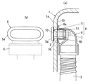
ところで、オーバーフロー管の口金具はさまざまな方法で洗面ボウルの開口部に取り付けられており、例えば図5(a)に示すように、口金具4’を洗面ボウル1の裏面1bに対してネジ8で固定する方法が一般的である。   By the way, the mouthpiece of the overflow pipe is attached to the opening of the wash bowl by various methods. For example, as shown in FIG. The method of fixing with is common.

しかしながら、陶器からなる洗面ボウル1は表面1aは平滑性を有しているが、反対側の裏面1bは、通常、凹凸面形状となっており、このような凹凸面形状によって口金具4’との間に隙間Sが生じ、開口部2から流れ込んだオーバーフロー水がこの隙間Sから外部に水漏れするおそれがある。これを防止するために、例えば、洗面ボウル1の裏面1bを平滑にしたり、シリコンなどの止水材を使用したりすればよいが、施工数が増えるという問題がある。また、口金具4’を洗面ボウル1に対してネジ固定しているため、洗面ボウル1内部にナットを埋め込んだり、洗面ボウル1の肉厚を厚くして強度を持たせたりする必要があり、このため洗面ボウル1の成形サイクルが長くなるという問題がある。さらに、洗面ボウル1の開口部2には汚れが溜まりやすいため、例えば図5(b)に示す化粧リング12を接着剤13にて接着して、外観化粧を施すようにしているが、口金具4’とは別部材である化粧リング12の取り付けに手間がかかるという問題もある。
特開2007−120202号公報
However, the wash bowl 1 made of earthenware has a smooth surface 1a, but the back surface 1b on the opposite side usually has an uneven surface shape. There is a possibility that a gap S is generated between the two and the overflow water flowing from the opening 2 leaks from the gap S to the outside. In order to prevent this, for example, the back surface 1b of the wash bowl 1 may be smoothed or a water-stopping material such as silicon may be used, but there is a problem that the number of constructions increases. Further, since the fitting 4 'is fixed to the wash bowl 1 with screws, it is necessary to embed nuts in the wash bowl 1 or to increase the thickness of the wash bowl 1 to increase the strength. For this reason, there exists a problem that the shaping | molding cycle of the wash bowl 1 becomes long. Furthermore, since dirt easily accumulates in the opening 2 of the wash bowl 1, for example, a cosmetic ring 12 shown in FIG. There is also a problem that it takes time to attach the decorative ring 12 which is a member different from 4 ′.
JP 2007-120202 A

本発明は上記の従来の問題点に鑑みて発明したものであって、口金具の洗面ボウルへのネジ固定や接着が不要となり、これにより施工数を大幅に削減でき、また、洗面ボウルの裏面側で止水を行なわなくても洗面ボウルの裏面側への水漏れを確実に防止でき、さらに洗面ボウルの厚みを均一に薄くでき、これにより洗面ボウルの成形サイクルの短縮を図ることが可能なオーバーフロー管の口金部の取付構造を提供することを課題とするものである。   The present invention has been invented in view of the above-described conventional problems, and it is not necessary to fix or bond the mouth fitting to the wash bowl, thereby greatly reducing the number of constructions and the back of the wash bowl. Even without water stoppage on the side, water leakage to the back side of the wash bowl can be reliably prevented, and the wash bowl thickness can be evenly reduced, thereby shortening the wash bowl molding cycle. It is an object of the present invention to provide an attachment structure for a cap portion of an overflow pipe.

前記課題を解決するために本発明は、洗面ボウル1のオーバーフロー用の開口部2にオーバーフロー管3の口金具4を取り付ける構造であって、口金具4は、リング状の化粧カバー部5と、洗面ボウル1の裏面1b側のオーバーフロー管3に接続される筒状で側面からて略L字形に曲げられた口金本体部6とで構成され、上記化粧カバー部5は、洗面ボウル1の表面1a側に配置されるフランジ部5aと、洗面ボウル1の開口部2内に挿入されるカバー側接続筒5bとが一体に形成されており、上記口金本体部6は、上記カバー側接続筒5bの洗面ボウル1の裏面1b側に突出する部分が嵌入されて接続可能な本体側接続筒6bと、洗面ボウル1の裏面1bに当接可能な当接部6aとが一体に形成されており、本体側接続筒6bの外側にはネジ孔部6cを形成するボス6dが設けられ、カバー側接続筒5b後端と本体側接続筒6bとの間に止水パッキン11を挟み込み、上記化粧カバー部5のフランジ部5aと口金本体部6の当接部6aとを洗面ボウル1の表・裏面1a,1bに各々対向させた状態で、カバー側接続筒5bの開口部2内に位置する部分に設けた洗面ボウル1の裏面1b側に開口するネジ孔部5cと上記本体側接続筒6bに設けたネジ孔部6cとを組立用のネジ7で締結することで、化粧カバー部5が口金本体部6側に引き寄せられて化粧カバー部5と口金本体部6とが洗面ボウル1が挟み込むようにして取り付けられることを特徴としている。
In order to solve the above-mentioned problem, the present invention is a structure in which a mouth fitting 4 of an overflow pipe 3 is attached to an overflow opening 2 of a wash bowl 1, and the mouth fitting 4 includes a ring-shaped decorative cover portion 5, It comprises a base body portion 6 that is connected to the overflow pipe 3 on the back surface 1b side of the wash bowl 1 and is bent in a substantially L shape when viewed from the side, and the decorative cover portion 5 is a surface of the wash bowl 1 A flange portion 5a arranged on the 1a side and a cover side connecting tube 5b inserted into the opening 2 of the wash bowl 1 are integrally formed, and the base body portion 6 is formed of the cover side connecting tube 5b. A body-side connecting tube 6b that can be connected by inserting a portion protruding to the back surface 1b side of the wash bowl 1 and a contact portion 6a that can come into contact with the back surface 1b of the wash bowl 1 are integrally formed, On the outside of the main body side connecting cylinder 6b A boss 6d for forming a hole 6c is provided, and a water-stopping packing 11 is sandwiched between the rear end of the cover side connection tube 5b and the main body side connection tube 6b, and the flange portion 5a of the decorative cover portion 5 and the base body portion The back surface 1b side of the wash bowl 1 provided in the portion located in the opening 2 of the cover side connecting tube 5b with the abutment portion 6a of the face 6 facing the front and back surfaces 1a, 1b of the wash bowl 1 respectively. The decorative cover portion 5 is drawn toward the base body portion 6 side by fastening the screw hole portion 5c that opens to the screw body and the screw hole portion 6c provided in the main body side connection cylinder 6b with the assembly screw 7, so that the decorative cover The part 5 and the base body part 6 are attached so that the wash bowl 1 is sandwiched.

このような構成とすることで、化粧カバー部5と口金本体部6とをネジ7で締結するだけで、口金本体部6と化粧カバー部5とで洗面ボウル1を表・裏面1a,1bから挟み込んで取り付けることができると共に、カバー側接続筒5bと本体側接続筒6bとが接続されて口金具4の組立が完了すると同時に、開口部2に対する口金具4の取り付け作業が完了する。従って、従来のような洗面ボウル1に対するネジ固定が一切不要となり、化粧カバー部5を開口部2側に別途接着する必要もない。また、口金具4を洗面ボウル1に対してネジ固定する必要がないため、洗面ボウル1を均等な厚みで成形可能となる。さらに、ネジ7の締め付け力が化粧カバー部5を口金本体部6側に引き寄せる方向に作用するので、化粧カバー部5と洗面ボウル1の表面1aとの密着性が良好となって洗面ボウル1の表面1a側が封水構造となるので、洗面ボウル1の裏面1b側への水漏れを確実に防止できるようになる。   With such a configuration, the wash bowl 1 can be removed from the front and back surfaces 1a and 1b by simply fastening the decorative cover portion 5 and the base body portion 6 with the screws 7, and the base body portion 6 and the decorative cover portion 5 together. At the same time, the cover side connecting cylinder 5b and the main body side connecting cylinder 6b are connected to complete the assembly of the cap 4 and, at the same time, the mounting operation of the cap 4 to the opening 2 is completed. Therefore, there is no need for screw fixing to the wash bowl 1 as in the prior art, and there is no need to separately bond the decorative cover portion 5 to the opening 2 side. Further, since it is not necessary to fix the mouthpiece 4 to the wash bowl 1, the wash bowl 1 can be formed with a uniform thickness. Further, since the tightening force of the screw 7 acts in the direction of pulling the decorative cover portion 5 toward the base body portion 6, the adhesion between the decorative cover portion 5 and the surface 1 a of the wash bowl 1 becomes good, and the wash bowl 1 Since the surface 1a side has a water-sealing structure, water leakage to the back surface 1b side of the wash bowl 1 can be reliably prevented.

また、上記化粧カバー部5と洗面ボウル1の表面1aとの間に、ネジ7の締め付け力を受けて化粧カバー部5のフランジ部5aと洗面ボウル1の表面1aとに密着する止水パッキン10を設けたことを特徴とするのが好ましく、この場合、ネジ7の締め付け力を利用して止水パッキン10による洗面ボウル1の表面1a側での封水効果をより一層高めることができる。   Further, between the decorative cover portion 5 and the surface 1 a of the wash bowl 1, a waterproof seal 10 that receives the tightening force of the screw 7 and adheres closely to the flange portion 5 a of the decorative cover portion 5 and the surface 1 a of the wash bowl 1. In this case, the water sealing effect on the surface 1a side of the wash bowl 1 by the water-stopping packing 10 can be further enhanced by using the tightening force of the screw 7.

本発明は、口金具を構成する口金本体部と化粧カバー部とで洗面ボウルを表・裏面から挟み込むようにしてネジで組み立てることにより、従来のような洗面ボウルへのネジ固定や化粧カバー部の別途接着が不要となり、施工数を大幅に削減できるものであり、また、洗面ボウルの表面側における封水構造によって洗面ボウルの裏面側への水漏れを確実に防止できるので、従来のように洗面ボウルの裏面側で止水を行なう必要がないものであり、さらに洗面ボウルの厚みを均一にでき、洗面ボウルの成形サイクルを短縮できるという効果を奏するものである。   The present invention assembles a wash bowl with screws so as to sandwich the wash bowl from the front and back surfaces of the base body part and the decorative cover part that constitute the metal fittings, thereby fixing the screw to the wash bowl as in the past and the decorative cover part. Since no separate bonding is required, the number of installations can be significantly reduced, and the water-sealing structure on the front side of the wash bowl can reliably prevent water leakage to the back side of the wash bowl, so There is no need to stop the water on the back side of the bowl, and the thickness of the wash bowl can be made uniform and the molding cycle of the wash bowl can be shortened.

以下、本発明を添付図面に示す実施形態に基いて説明する。   Hereinafter, the present invention will be described based on embodiments shown in the accompanying drawings.

図1は本発明の実施形態に用いる口金具4を洗面ボウル1のオーバーフロー用の開口部2に取り付けた状態を説明する平面図であり、図2(a)は側面断面図であり、(b)は正面図である。   FIG. 1 is a plan view for explaining a state in which the mouthpiece 4 used in the embodiment of the present invention is attached to the overflow opening 2 of the wash bowl 1, FIG. 2 (a) is a side sectional view, ) Is a front view.

オーバーフロー管3の口金具4は、錆難く腐食し難い、例えばステンレス材にて形成されており、リング状の化粧カバー部5と、筒状の口金本体部6とで構成されている。   The fitting 4 of the overflow pipe 3 is made of, for example, a stainless material that is not easily rusted and corroded, and includes a ring-shaped decorative cover portion 5 and a cylindrical mouthpiece main body portion 6.

洗面ボウル1の表面1a側に配置される化粧カバー部5は、図3に示すように、洗面ボウル1の横長状の開口部2と同じ横長リング状に形成されている。化粧カバー部5は、洗面ボウル1の表面1a側から開口部2周辺をカバーするフランジ部5aと、洗面ボウル1の開口部2内に挿入されて口金本体部6と接続されるカバー側接続筒5bとが一体に形成されている。カバー側接続筒5bの左右両外側はそれぞれ、図3(a)(d)に示すように厚肉部分となってネジ孔部5cが形成されており、各ネジ孔部5cは後方側(口金本体部6側)に向かってそれぞれ開口している。なお、カバー側接続筒5bの長さは、フランジ部5aが洗面ボウル1の表面1aに当たった状態でカバー側接続筒5b後端が洗面ボウル1の裏面1bよりも背後に突出して口金本体部6内に嵌入する長さに設定される。   As shown in FIG. 3, the decorative cover portion 5 disposed on the surface 1 a side of the wash bowl 1 is formed in the same horizontally long ring shape as the horizontally long opening 2 of the wash bowl 1. The decorative cover portion 5 includes a flange portion 5a that covers the periphery of the opening 2 from the surface 1a side of the wash bowl 1, and a cover side connecting tube that is inserted into the opening 2 of the wash bowl 1 and connected to the base body portion 6. 5b is integrally formed. As shown in FIGS. 3A and 3D, the left and right outer sides of the cover-side connecting cylinder 5b are thick portions to form screw holes 5c, and each screw hole 5c is formed on the rear side (the base). Opening toward the main body 6 side). The length of the cover-side connecting tube 5b is such that the rear end of the cover-side connecting tube 5b protrudes behind the back surface 1b of the wash bowl 1 with the flange portion 5a contacting the surface 1a of the wash bowl 1. 6 is set to a length that fits into the inside.

一方、洗面ボウル1の裏面1b側に配置される口金本体部6は、図4に示すように、カバー側接続筒5bと同じ横長筒状に形成されていると共に、側面から見て略L字形に曲げられており、その下端部6eにはオーバーフロー管3の上端が接続される。オーバーフロー管3は例えば蛇腹状のフレキシブルパイプで構成され、その下端は例えば洗面ボウル1の排水トラップ(図示せず)に接続される。   On the other hand, as shown in FIG. 4, the base body 6 disposed on the back surface 1b side of the wash bowl 1 is formed in the same horizontally long cylinder shape as the cover side connection cylinder 5b, and is substantially L-shaped when viewed from the side. The upper end of the overflow pipe 3 is connected to the lower end portion 6e thereof. The overflow pipe 3 is composed of, for example, a bellows-like flexible pipe, and its lower end is connected to, for example, a drain trap (not shown) of the wash bowl 1.

上記口金本体部6の上端部には本体側接続筒6bが設けられている。本体側接続筒6bは上記カバー側接続筒5b後端に水密的に接続可能な寸法形状を有している。本体側接続筒6bの左右両外側には、図4(a)に示すネジ孔部6cを形成するボス6dが設けられており、このネジ孔部6cが上記カバー側接続筒5bの左右2個のネジ孔部5cと各々対応している。さらに口金本体部6の外周には、洗面ボウル1の裏面1bに当接可能なつば状の当接部6aが突設されている。この当接部6aはネジ7の締結時において洗面ボウル1の裏面1bに当たることで口金本体部6が開口部2内に引き込まれるのを防止する役目をする。   A main body side connecting tube 6 b is provided at the upper end of the base body 6. The main body side connecting cylinder 6b has a dimension that can be connected in a watertight manner to the rear end of the cover side connecting cylinder 5b. A boss 6d forming a screw hole portion 6c shown in FIG. 4A is provided on the left and right outer sides of the main body side connection tube 6b. The screw hole portions 6c are provided on the left and right sides of the cover side connection tube 5b. Respectively corresponding to the screw hole portions 5c. Further, on the outer periphery of the base body portion 6, a collar-like contact portion 6 a that can contact the back surface 1 b of the wash bowl 1 is projected. The abutment portion 6 a serves to prevent the base body portion 6 from being pulled into the opening 2 by hitting the back surface 1 b of the wash bowl 1 when the screw 7 is fastened.

また本例では、図1、図2に示すように、上記化粧カバー部5のフランジ部5aと洗面ボウル1の表面1aとの間に、ネジ7の締め付け力を受けて化粧カバー部5のフランジ部5aと洗面ボウル1の表面1aとに密着するリング状の止水パッキン10が介在されている。さらに上記カバー側接続筒5bと上記本体側接続筒6bとの間にも、ネジ7の締め付け力を受けるリング状の止水パッキン11が介在されている。これら止水パッキン10,11は、弾力性を有し、錆難く腐食し難い材料、例えばゴム等で形成されている。   Further, in this example, as shown in FIGS. 1 and 2, the flange of the decorative cover portion 5 receives the tightening force of the screw 7 between the flange portion 5 a of the decorative cover portion 5 and the surface 1 a of the wash bowl 1. A ring-shaped water-proof packing 10 that is in close contact with the portion 5a and the surface 1a of the wash bowl 1 is interposed. Further, a ring-shaped water-stopping packing 11 that receives the tightening force of the screw 7 is interposed between the cover-side connecting cylinder 5b and the main-body-side connecting cylinder 6b. These water-proof packings 10 and 11 are made of a material that has elasticity and is not easily rusted and corroded, such as rubber.

次に、上記口金具4を洗面ボウル1の開口部2に取り付ける作業の手順の一例を説明する。   Next, an example of a procedure for attaching the mouthpiece 4 to the opening 2 of the wash bowl 1 will be described.

先ず、化粧カバー部5のフランジ部5aと口金本体部6の当接部6aとを洗面ボウル1の表・裏面1a,1bに各々対向させると共に、フランジ部5aと洗面ボウル1の表面1aとの間に止水パッキン10を挟み込む。このとき、カバー側接続筒5b後端が口金本体部6内に嵌入して本体側接続筒6b前端と対向すると共に、カバー側接続筒5b外側のネジ孔部5cが本体側接続筒6b外側のネジ孔部6cと対向するようになる。そして、カバー側接続筒5b後端と本体側接続筒6b前端との間に止水パッキン11を挟み込んだ状態で、洗面ボウル1の裏面1b側から組立用のネジ7をネジ孔部6cを通してネジ孔部5cに締め込む。これにより、化粧カバー部5が口金本体部6側に引き寄せられて、化粧カバー部5のフランジ部5aと口金本体部6の当接部6aとが洗面ボウル1の表・裏面1a,1bをそれぞれ挟圧するようになり、これにより、化粧カバー部5と口金本体部6とが洗面ボウル1を挟み込むようにして取り付けられるようになり、さらに止水パッキン11を介してカバー側接続筒5bと本体側接続筒6bとが水密的に接続された状態となって、口金具4の組立が完了するものであり、また同時に、開口部2に対する口金具4の取り付け作業も完了する。   First, the flange portion 5a of the decorative cover portion 5 and the abutting portion 6a of the base body portion 6 are respectively opposed to the front and back surfaces 1a and 1b of the wash bowl 1, and the flange portion 5a and the front surface 1a of the wash bowl 1 are formed. The water blocking packing 10 is sandwiched between them. At this time, the rear end of the cover-side connecting cylinder 5b is fitted into the base body 6 and faces the front end of the main-body connecting cylinder 6b, and the screw hole 5c outside the cover-side connecting cylinder 5b is located outside the main body-side connecting cylinder 6b. It comes to face the screw hole 6c. Then, with the water-stopping packing 11 sandwiched between the rear end of the cover side connecting cylinder 5b and the front end of the main body side connecting cylinder 6b, an assembly screw 7 is screwed through the screw hole 6c from the back surface 1b side of the wash bowl 1 Tighten into the hole 5c. Thereby, the decorative cover part 5 is drawn toward the base body part 6 side, and the flange part 5a of the decorative cover part 5 and the contact part 6a of the base body part 6 respectively connect the front and back surfaces 1a and 1b of the wash bowl 1 respectively. As a result, the decorative cover portion 5 and the base body portion 6 are attached so as to sandwich the wash bowl 1, and the cover side connecting cylinder 5 b and the main body side via the water-stopping packing 11. The connection tube 6b is connected in a watertight manner, and the assembly of the cap 4 is completed. At the same time, the attaching operation of the cap 4 to the opening 2 is also completed.

しかして、上記口金具4を構成する化粧カバー部5と口金本体部6とを組立用のネジ7で締結するだけで、口金本体部6と化粧カバー部5とで洗面ボウル1を表・裏面1a,1bから挟み込んで取り付けることができるので、従来のような洗面ボウル1にネジ固定したり、化粧カバー部5を別途接着したりする必要がない。しかもネジ7を締結するだけで、口金具4の組み立て開口部2への取り付けとが同時にできるので、作業工数を大幅に削減できる利点がある。   Thus, by simply fastening the decorative cover portion 5 and the base body portion 6 constituting the base metal fitting 4 with the assembly screws 7, the front and back surfaces of the wash bowl 1 can be formed by the base body portion 6 and the decorative cover portion 5. Since it can be sandwiched and attached from 1a and 1b, there is no need to screw and attach the decorative cover part 5 to the wash bowl 1 as in the prior art. Moreover, since the fitting 4 can be attached to the assembly opening 2 at the same time by simply fastening the screw 7, there is an advantage that the number of work steps can be greatly reduced.

また、口金具4の各部品を洗面ボウル1に対してネジ固定する必要がないため、従来のように洗面ボウル1内部にナットを埋め込んだり、洗面ボウル1を厚くして強度を持たせたりする必要がなくなり、洗面ボウル1を均等厚みで成形可能となるので、洗面ボウル1の成形サイクルを短縮できる利点がある。   Further, since it is not necessary to fix each part of the mouthpiece 4 to the wash bowl 1, a nut is embedded in the wash bowl 1 as in the past, or the wash bowl 1 is thickened to give strength. There is no need, and the wash bowl 1 can be formed with a uniform thickness. Therefore, there is an advantage that the forming cycle of the wash bowl 1 can be shortened.

さらに、ネジ7の締め付け力が化粧カバー部5を口金本体部6側に引き寄せる方向に作用するので、化粧カバー部5のフランジ部5aと平滑性を有する洗面ボウル1の表面1aとの密着性がよくなって洗面ボウル1の表面1a側で封水構造となり、従って、洗面ボウル1の裏面1b側への水漏れを確実に防止できるようになる。また本例では、上記化粧カバー部5と洗面ボウル1の表面1aとの間に、ネジ7の締め付けによって洗面ボウル1の表面1aに密着する止水パッキン10を設けたことによって、ネジ7の締め付け力を利用して止水パッキン10による洗面ボウル1の表面1a側での封水効果をより一層高めることができる。従って、従来のように洗面ボウル1の裏面1b側で止水を行なう必要がなくなり、洗面ボウル1の裏面1bは凹凸面のままでよく、平滑性にする必要がないものである。さらに本例では、カバー側接続筒5bと本体側接続筒6bとの接続面にも止水パッキン11が介在されており、この止水パッキン11もまたネジ7の締め付けによってカバー側接続筒5bと本体側接続筒6bとの接続面間で圧着されるので、口金具4の接続部分での水密性が向上する利点もある。   Further, since the tightening force of the screw 7 acts in the direction of pulling the decorative cover part 5 toward the base body part 6, the adhesion between the flange part 5a of the decorative cover part 5 and the surface 1a of the wash bowl 1 having smoothness is improved. As a result, a water-sealing structure is formed on the surface 1a side of the wash bowl 1, so that water leakage to the back surface 1b side of the wash bowl 1 can be reliably prevented. Moreover, in this example, the water-stopping packing 10 that is in close contact with the surface 1 a of the wash bowl 1 by tightening the screw 7 is provided between the decorative cover portion 5 and the surface 1 a of the wash bowl 1, thereby tightening the screw 7. The water sealing effect on the surface 1a side of the wash bowl 1 by the water stop packing 10 can be further enhanced by using the force. Therefore, it is not necessary to stop the water on the back surface 1b side of the wash bowl 1 as in the prior art, and the back surface 1b of the wash bowl 1 may be an uneven surface and does not need to be smooth. Furthermore, in this example, the water-stopping packing 11 is also interposed on the connection surface between the cover-side connecting tube 5b and the main-body-side connecting tube 6b. The water-stopping packing 11 is also connected to the cover-side connecting tube 5b by tightening the screws 7. Since it is crimped | bonded between connection surfaces with the main body side connection cylinder 6b, there also exists an advantage which the water-tightness in the connection part of the metal fitting 4 improves.

前記実施形態では、洗面ボウル1の開口部2が長穴状の場合を例示したが、勿論、丸穴であってもよいものであり、この場合、化粧カバー部5及び口金本体部6の形状を丸型にすればよいものであり、開口部2の異なる形状にも対応可能である。   In the said embodiment, although the case where the opening part 2 of the wash bowl 1 was a long hole shape was illustrated, of course, a round hole may be sufficient, In this case, the shape of the makeup | decoration cover part 5 and the nozzle | cap | die main body part 6 is used. Can be round, and can correspond to different shapes of the opening 2.

本発明の一実施形態に用いる口金具を洗面ボウルの開口部に取り付けた状態を説明する平面図である。It is a top view explaining the state which attached the metal fitting used for one Embodiment of this invention to the opening part of the wash bowl. (a)は同上の口金具の取り付け状態を説明する側面断面図、(b)は正面図である。(A) is side sectional drawing explaining the attachment state of a cap metal fitting same as the above, (b) is a front view. 同上の化粧カバー部の洗面ボウルへの取り付け状態を示し、(a)は一部破断した平面図、(b)は正面図、(c)は一部破断した側面図、(d)は背面図である。The attachment state of the same cosmetic cover part to the wash bowl is shown, (a) is a partially broken plan view, (b) is a front view, (c) is a partially broken side view, and (d) is a rear view. It is. 同上の口金本体部を示し、(a)は一部破断した正面図、(b)は一部破断した平面図、(c)は左側面図、(d)は右側面断面図、(e)は下面図である。The base body of the above is shown, (a) is a partially broken front view, (b) is a partially broken plan view, (c) is a left side view, (d) is a right side sectional view, (e) Is a bottom view. (a)は従来例の口金具の取り付け状態を説明する側面断面図、(b)は化粧リングの正面図である。(A) is side surface sectional drawing explaining the attachment state of the metal fitting of a prior art example, (b) is a front view of a decorative ring.

符号の説明Explanation of symbols

1 洗面ボウル
1a 表面
1b 裏面
2 開口部
3 オーバーフロー管
4 口金具
5 化粧カバー部
5a フランジ部
5b カバー側接続筒
6 口金本体部
6a 当接部
6b 本体側接続筒
7 ネジ
10 止水パッキン
DESCRIPTION OF SYMBOLS 1 Washing bowl 1a Front surface 1b Back surface 2 Opening part 3 Overflow pipe 4 Mouth fitting 5 Cosmetic cover part 5a Flange part 5b Cover side connection cylinder 6 Base body part 6a Contact part 6b Main body side connection cylinder 7 Screw 10 Water stop packing

Claims (2)

洗面ボウルのオーバーフロー用の開口部にオーバーフロー管の口金具を取り付ける構造であって、口金具は、リング状の化粧カバー部と、洗面ボウルの裏面側のオーバーフロー管に接続される筒状で側面から見て略L字形に曲げられた口金本体部とで構成され、上記化粧カバー部は、洗面ボウルの表面側に配置されるフランジ部と、洗面ボウルの開口部内に挿入されるカバー側接続筒とが一体に形成されており、上記口金本体部は、上記カバー側接続筒の洗面ボウルの裏面側に突出する部分が嵌入されて接続可能な本体側接続筒と、洗面ボウルの裏面に当接可能な当接部とが一体に形成されており、本体側接続筒の外側にはネジ孔部を形成するボスが設けられ、カバー側接続筒後端と本体側接続筒との間に止水パッキンを挟み込み、上記化粧カバー部のフランジ部と口金本体部の当接部とを洗面ボウルの表・裏面に各々対向させた状態で、カバー側接続筒の開口部内に位置する部分に設けた洗面ボウルの裏面側に開口するネジ孔部と上記本体側接続筒に設けたネジ孔部とを組立用のネジで締結することで、化粧カバー部が口金本体部側に引き寄せられて化粧カバー部と口金本体部とが洗面ボウルが挟み込むようにして取り付けられることを特徴とするオーバーフロー管の口金具の取付構造。 An overflow pipe fitting is attached to the overflow opening of the wash bowl, and the fitting is a ring-shaped decorative cover and a cylindrical shape connected to the overflow pipe on the back side of the wash bowl from the side. A base body part bent into a substantially L shape when viewed, and the decorative cover part includes a flange part disposed on the surface side of the wash bowl, and a cover side connecting cylinder inserted into the opening part of the wash bowl. Is formed integrally, and the base body part can contact the body-side connecting tube that can be connected by inserting the protruding part on the back side of the wash bowl of the cover-side connection tube , and the back surface of the wash bowl And a boss that forms a screw hole on the outside of the main body side connection tube, and a water-tight packing between the rear end of the cover side connection tube and the main body side connection tube. Sandwich the above makeup In a state where each is opposed to the contact portion of the flange portion of the bar portion and the base body portion to the front and back side of the washbowl, opening on the back side of the washbowl provided in the portion located in the opening of the cover-side connecting tube By fastening the screw hole part to the screw body part and the screw hole part provided in the main body side connection cylinder with the screws for assembly, the decorative cover part is drawn to the base body part side, and the decorative cover part and the base body part are washed. An attachment structure for an overflow pipe fitting, wherein the bowl is attached so as to be sandwiched. 上記化粧カバー部と洗面ボウルの表面との間に、ネジの締め付け力を受けて化粧カバー部のフランジ部と洗面ボウルの表面とに密着する止水パッキンを設けたことを特徴とする請求項1記載のオーバーフロー管の口金具の取付構造。   2. A waterproof seal is provided between the decorative cover portion and the surface of the wash bowl, and receives a tightening force of a screw to closely contact the flange portion of the decorative cover portion and the surface of the wash bowl. Mounting structure for the overflow pipe fitting described.
JP2007248165A 2007-09-25 2007-09-25 Overflow pipe fitting mounting structure Active JP5519903B2 (en)

Priority Applications (1)

Application Number Priority Date Filing Date Title
JP2007248165A JP5519903B2 (en) 2007-09-25 2007-09-25 Overflow pipe fitting mounting structure

Applications Claiming Priority (1)

Application Number Priority Date Filing Date Title
JP2007248165A JP5519903B2 (en) 2007-09-25 2007-09-25 Overflow pipe fitting mounting structure

Related Child Applications (1)

Application Number Title Priority Date Filing Date
JP2014077192A Division JP5884052B2 (en) 2014-04-03 2014-04-03 Overflow pipe fitting mounting structure

Publications (2)

Publication Number Publication Date
JP2009077820A JP2009077820A (en) 2009-04-16
JP5519903B2 true JP5519903B2 (en) 2014-06-11

Family

ID=40653035

Family Applications (1)

Application Number Title Priority Date Filing Date
JP2007248165A Active JP5519903B2 (en) 2007-09-25 2007-09-25 Overflow pipe fitting mounting structure

Country Status (1)

Country Link
JP (1) JP5519903B2 (en)

Families Citing this family (2)

* Cited by examiner, † Cited by third party
Publication number Priority date Publication date Assignee Title
JP5200254B2 (en) * 2007-09-25 2013-06-05 丸一株式会社 Connection structure
JP5884052B2 (en) * 2014-04-03 2016-03-15 パナソニックIpマネジメント株式会社 Overflow pipe fitting mounting structure

Family Cites Families (7)

* Cited by examiner, † Cited by third party
Publication number Priority date Publication date Assignee Title
JPS4313592Y1 (en) * 1964-07-02 1968-06-10
JPS5885686U (en) * 1981-11-30 1983-06-10 松下電工株式会社 Bathtub overflow device
JPH09203093A (en) * 1995-11-21 1997-08-05 Noriatsu Kojima Pipe joint structure
JP2003056766A (en) * 2001-08-09 2003-02-26 Noriatsu Kojima Packing of drain pipe joint
JP2004156288A (en) * 2002-11-06 2004-06-03 Tanico Corp Overflow structure for sink and the like, and detachable catch basin for use in the same
JP2006236647A (en) * 2005-02-23 2006-09-07 Asahi Kasei Chemicals Corp Separator electrode integral power storage member
JP4565453B2 (en) * 2006-08-07 2010-10-20 株式会社日本アルファ Remote control drain plug device

Also Published As

Publication number Publication date
JP2009077820A (en) 2009-04-16

Similar Documents

Publication Publication Date Title
KR102304858B1 (en) High pressure hose connector for water pipe with anti-twist function
JP5519903B2 (en) Overflow pipe fitting mounting structure
JP5884052B2 (en) Overflow pipe fitting mounting structure
JP5311311B2 (en) Bathroom unit
JP2010037919A (en) Drain outlet structure
US4937899A (en) Lavatory with improved overflow duct assembly
JP5939481B2 (en) Drainage structure
JP5282937B2 (en) Overflow integrated drain fitting
JP2008206705A (en) Water receiving structure for bathtub
JPS6242044Y2 (en)
JP2003235752A (en) Bathroom structure
JP4561502B2 (en) Part mounting structure for molded products
CN210288592U (en) Bathtub drainer and bathtub
JP2018112000A (en) Connection structure of pipe body
KR200346304Y1 (en) A joint pipe for prevention of noise
JP2005253696A (en) Water receiving tray
JP3963713B2 (en) Connection structure of water pipe and joint member
JP2004092239A (en) Connecting structure for cylindrical member with member with through-hole part
JPH10318372A (en) Tightly connection packing and low tank tightly connection structure
JP2008274709A (en) Piping structure of waterproof pan of bathroom
KR200152778Y1 (en) Rubber ring for joint of a water pipe
KR960002852Y1 (en) Pipe joints
KR200271953Y1 (en) Water, tank
JPS6332200Y2 (en)
KR20200002519U (en) Flexible hose connector reinforcement structure

Legal Events

Date Code Title Description
A621 Written request for application examination

Free format text: JAPANESE INTERMEDIATE CODE: A621

Effective date: 20091023

RD04 Notification of resignation of power of attorney

Free format text: JAPANESE INTERMEDIATE CODE: A7424

Effective date: 20100817

A131 Notification of reasons for refusal

Free format text: JAPANESE INTERMEDIATE CODE: A131

Effective date: 20111220

A711 Notification of change in applicant

Free format text: JAPANESE INTERMEDIATE CODE: A712

Effective date: 20120112

A521 Written amendment

Free format text: JAPANESE INTERMEDIATE CODE: A523

Effective date: 20120220

A131 Notification of reasons for refusal

Free format text: JAPANESE INTERMEDIATE CODE: A131

Effective date: 20120828

A521 Written amendment

Free format text: JAPANESE INTERMEDIATE CODE: A523

Effective date: 20121029

A131 Notification of reasons for refusal

Free format text: JAPANESE INTERMEDIATE CODE: A131

Effective date: 20130521

A521 Written amendment

Free format text: JAPANESE INTERMEDIATE CODE: A523

Effective date: 20130722

TRDD Decision of grant or rejection written
A01 Written decision to grant a patent or to grant a registration (utility model)

Free format text: JAPANESE INTERMEDIATE CODE: A01

Effective date: 20140311

A61 First payment of annual fees (during grant procedure)

Free format text: JAPANESE INTERMEDIATE CODE: A61

Effective date: 20140404

R151 Written notification of patent or utility model registration

Ref document number: 5519903

Country of ref document: JP

Free format text: JAPANESE INTERMEDIATE CODE: R151