JP6380629B2 - Optical sensor and image forming apparatus - Google Patents
Optical sensor and image forming apparatus Download PDFInfo
- Publication number
- JP6380629B2 JP6380629B2 JP2017149720A JP2017149720A JP6380629B2 JP 6380629 B2 JP6380629 B2 JP 6380629B2 JP 2017149720 A JP2017149720 A JP 2017149720A JP 2017149720 A JP2017149720 A JP 2017149720A JP 6380629 B2 JP6380629 B2 JP 6380629B2
- Authority
- JP
- Japan
- Prior art keywords
- angle
- light
- recording medium
- optical sensor
- recording paper
- Prior art date
- Legal status (The legal status is an assumption and is not a legal conclusion. Google has not performed a legal analysis and makes no representation as to the accuracy of the status listed.)
- Active
Links
Images


Description
本発明は、光学センサ及び画像形成装置に関する。 The present invention relates to an optical sensor and an image forming apparatus.
デジタル複写機、レーザプリンタ等のいわゆる電子写真方式の画像形成装置は、記録紙等の記録媒体にトナー像を転写し、所定の条件で加熱及び加圧することにより、トナー像を記録紙等の記録媒体に定着させて画像を形成するものである。このような画像形成装置において考慮する必要があるのが、トナー像を定着する際の加熱量や圧力等の条件であり、特に、高画質な画像形成を行う際には、トナー像を定着するための条件を記録媒体の種類に応じて個別に設定する必要がある。 A so-called electrophotographic image forming apparatus such as a digital copying machine or a laser printer transfers a toner image onto a recording medium such as a recording paper, and records the toner image on a recording paper or the like by heating and pressing under a predetermined condition. An image is formed by fixing on a medium. In such an image forming apparatus, it is necessary to consider conditions such as a heating amount and a pressure when fixing a toner image. In particular, when forming a high-quality image, the toner image is fixed. It is necessary to individually set the conditions for this according to the type of the recording medium.
これは記録媒体に記録される画像品質が、記録媒体の材質、厚さ、湿度、平滑性及び塗工状態等により大きく影響されるためである。特に平滑性に関しては、定着の際の条件によっては、記録媒体の凹部におけるトナーの定着率が低くなり、高画質な画像を得ることができない。 This is because the image quality recorded on the recording medium is greatly influenced by the material, thickness, humidity, smoothness, coating state, and the like of the recording medium. In particular, regarding smoothness, depending on the fixing conditions, the toner fixing rate in the concave portion of the recording medium becomes low, and a high-quality image cannot be obtained.
一方、製紙業界等においては、記録紙等の紙における表面状態の指標として、測定方法が簡便なエアリーク試験による測定結果に基づき紙の平滑度が評価されている。この平滑度の指標は紙に関する業界で使用されており、例えば、複写機の開発においても、紙の平滑度を基準の一つとして、印刷条件を最適化するべく開発が行なわれてきた。即ち、紙の表面状態を示す指標としては、2乗平均高さRa等の一般的な表面の状態を示す指標よりも、エアリーク試験による測定結果が利用されている。 On the other hand, in the paper manufacturing industry and the like, the smoothness of paper is evaluated based on the measurement result of an air leak test with a simple measuring method as an index of the surface state of paper such as recording paper. This smoothness index is used in the paper industry. For example, in the development of a copying machine, development has been made to optimize printing conditions using the smoothness of paper as one of the standards. That is, as an index indicating the paper surface state, a measurement result by an air leak test is used rather than an index indicating a general surface state such as the root mean square height Ra.
しかしながら、エアリーク試験は測定が簡便であるものの、装置が大型化し、かつ、測定に時間を要するといった問題点を有している。このため、低価格で、画像形成装置等の装置内に設置することができ、エアリーク試験と同様の紙の表面状態、即ち、平滑性を検査することのできる小型なセンサが求められていた。 However, although the air leak test is easy to measure, there are problems that the apparatus becomes large and the measurement takes time. For this reason, there has been a demand for a small sensor that can be installed in an apparatus such as an image forming apparatus at a low price and can inspect the surface condition of the paper, that is, the smoothness, similar to the air leak test.
記録紙等の記録媒体識別センサとしては、特許文献1に記載されているように触針式プローブにより表面の摩擦抵抗を検知する方法や、特許文献2に記載されているように、圧力センサ等により記録媒体のコシ(剛度)を検知する方法がある。また、特許文献3に記載されているように、非接触で記録媒体を識別する方法として、記録媒体の表面をエリアセンサ等の撮像素子により撮像し、撮像された画像より記録媒体の種類等を識別する方法がある。
As a recording medium identification sensor such as recording paper, a method of detecting a frictional resistance of a surface with a stylus probe as described in
また、他の非接触による記録媒体の識別方式としては反射光方式がある。反射光方式では、発光ダイオード(LED:Light Emitting Diode)等の光源から発せられた光を識別対象となる記録媒体に照射し、記録媒体からの反射光量により記録媒体の銘柄等を識別する方法である。この反射光方式は、以下の3種類の方法がある。 Another non-contact recording medium identification method is a reflected light method. In the reflected light system, light emitted from a light source such as a light emitting diode (LED) is irradiated onto a recording medium to be identified, and the brand of the recording medium is identified by the amount of light reflected from the recording medium. is there. This reflected light system has the following three methods.
第1の方法は、特許文献4に記載されているように、記録媒体の表面に照射された光の正反射方向における反射光の光量を検出し、検出された正反射方向における光量に基づき記録媒体の銘柄等を識別する方法である。より具体的には、特許文献4では、正反射方向における光量と、紙を透過した光量を検出して、記録媒体の銘柄を識別している。従って、正反射方向の光量のみで、識別しているわけではない。 As described in Patent Document 4, the first method detects the amount of reflected light in the regular reflection direction of light irradiated on the surface of a recording medium, and records based on the detected amount of light in the regular reflection direction. This is a method for identifying the brand of the medium. More specifically, in Patent Document 4, the brand of the recording medium is identified by detecting the amount of light in the regular reflection direction and the amount of light transmitted through the paper. Therefore, the identification is not performed only by the amount of light in the regular reflection direction.
第2の方法は、特許文献5に記載されているように、光量検出部を複数有するものである。具体的には、記録媒体の表面に照射された光の正反射方向における反射光の光量のみならず、散乱反射光の光量を検出し、検出された正反射方向における光量及び散乱反射光の光量に基づき記録媒体の銘柄等を識別する方法である。 As described in Patent Literature 5, the second method includes a plurality of light amount detection units. Specifically, it detects not only the amount of reflected light in the regular reflection direction of the light irradiated on the surface of the recording medium but also the amount of scattered reflected light, and the detected amount of light in the regular reflection direction and the amount of scattered reflected light. This is a method for identifying brands and the like of recording media based on the above.
第3の方法は、特許文献6に記載されているように、記録媒体の表面に照射された光の正反射方向における反射光を偏光ビームスプリッタにより分離し、分離された光の光量を測定し、測定された光量に基づき記録媒体の銘柄等を識別する方法である。 In the third method, as described in Patent Document 6, the reflected light in the regular reflection direction of the light irradiated on the surface of the recording medium is separated by a polarization beam splitter, and the light quantity of the separated light is measured. In this method, the brand of the recording medium is identified based on the measured light quantity.
一方、異物検査等の方法としては、特許文献7及び8に記載されている検査装置及び検査方法が存在している。 On the other hand, there are inspection apparatuses and inspection methods described in Patent Documents 7 and 8 as methods for foreign matter inspection and the like.
特許文献5に示されているような、一般的に知られている光学素子に比べ、入射角を70°〜88°とかなり浅い角度で検出し、また、検出取り込み角を全角10°以下とすることで検出精度向上を図る手法に関しては、特許文献9に詳細が記載されている。 Compared with a generally known optical element as shown in Patent Document 5, the incident angle is detected at a considerably shallow angle of 70 ° to 88 °, and the detection capture angle is 10 ° or less. Details of the technique for improving the detection accuracy by doing so are described in Patent Document 9.
しかしながら、特許文献1及び2に記載されている方法は、接触方式であるため、記録媒体である記録紙等の表面に傷をつけてしまうといった問題点を有している。また、特許文献3から6に記載されている方法では、エアリーク試験のような詳細に記録媒体の平滑度を検出するほどの精度ではない。
However, since the methods described in
また、特許文献9に記載のように、記録媒体で散乱した光の散乱角度の取り込み角を小さくすればするほど、原理的には、検出精度は向上することが予想される。しかしながら、実際のセンサとしては、アパーチャーが非常に小さくなってしまい、アパーチャー形状の加工精度、および、アパーチャーを通過する光量が非常に小さくなってしまう。このような光量の低下により、ノイズの影響を受けるため、検出精度の低下を招く。特許文献9では、高精度のアパーチャー形状を維持できる高品質な部品加工工法、材料を利用することで、公差を極限にまで小さくし、かつ、超高感度で耐ノイズ性に優れた検出器を利用することで、紙の平滑度を検出することが実現できていた。 Further, as described in Patent Document 9, in principle, it is expected that the detection accuracy is improved as the capturing angle of the scattering angle of the light scattered by the recording medium is reduced. However, as an actual sensor, the aperture becomes very small, and the processing accuracy of the aperture shape and the amount of light passing through the aperture become very small. Such a decrease in the amount of light is affected by noise, which leads to a decrease in detection accuracy. In Patent Document 9, a high-quality component processing method and materials that can maintain a highly accurate aperture shape are used to reduce the tolerance to the utmost limit, and to a detector that is ultra-sensitive and excellent in noise resistance. By using this, it was possible to detect the smoothness of the paper.
しかし、製造コストを考えた場合、樹脂など低コスト材料のアパーチャーやシリコン製のフォトダイオードなどを利用することが望まれる。そのためには、できるかぎり大きな光量を得ることが求められる。つまり、できるだけ大きいアパーチャー形状で、かつ、検出精度を向上させることが望まれている。 However, considering the manufacturing cost, it is desirable to use an aperture of a low-cost material such as a resin, a photodiode made of silicon, or the like. For that purpose, it is required to obtain as much light as possible. That is, it is desired that the aperture shape be as large as possible and the detection accuracy be improved.
本発明は、上記を鑑みなされたものであり、記録媒体の識別を高精度で行うことができる小型の光学センサを低コストで提供することを目的とするものである。 The present invention has been made in view of the above, and an object of the present invention is to provide a small optical sensor capable of identifying a recording medium with high accuracy at low cost.
本実施の形態の一観点によれば、光源と、前記光源より出射された光を記録媒体に照射し、前記記録媒体における正反射光の強度を検出する光検出器と、を有し、前記記録媒体の表面の法線に対し、前記光源と前記記録媒体上に形成される照射エリア中心とを結んだ光軸の角度θ1は、75°≦θ1≦85°であって、前記記録媒体の表面の法線に対し、前記記録媒体上に形成される照射エリア中心と前記光検出器とを結んだ光軸の角度θ2を角度θ1と同じとし、前記角度θ2よりも角度が小さい側の広がり角をθx1とし、前記角度θ2よりも角度が大きい側の広がり角をθx2とし、前記記録媒体の表面の法線に対し、前記記録媒体上の照射エリアにおいて反射された反射光のうち、前記光検出器に入射する光の角度θとした場合、
|θx1|>|θx2|
θx1+θ1<θ<θx2+θ1
を満たすものであって、取り込み全角度幅となる|θx1|+|θx2|は、5°≦|θx1|+|θx2|≦15°であることを特徴とする。
According to one aspect of this embodiment includes a light source, irradiating the recording medium with light emitted from the light source, a photodetector for detecting the intensity of the specular reflection light in the recording medium, wherein the The angle θ1 of the optical axis connecting the light source and the center of the irradiation area formed on the recording medium with respect to the normal of the surface of the recording medium is 75 ° ≦ θ1 ≦ 85 ° , and The angle θ2 of the optical axis connecting the center of the irradiation area formed on the recording medium and the photodetector is the same as the angle θ1 with respect to the surface normal, and the spread is on the side where the angle is smaller than the angle θ2. Of the reflected light reflected in the irradiated area on the recording medium with respect to the normal of the surface of the recording medium, the angle is θx1, the spread angle on the side larger than the angle θ2 is θx2, and the light When the angle of light incident on the detector is θ,
| Θx1 |> | θx2 |
θx1 + θ1 <θ <θx2 + θ1
What der satisfy the, the incorporation full angular width | θx1 | + | θx2 | is, 5 ° ≦ | θx1 | + | θx2 | a ≦ 15 ° der wherein Rukoto.
本発明によれば、記録媒体の識別を高い精度で行うことができる小型の光学センサを低コストで提供することができる。 ADVANTAGE OF THE INVENTION According to this invention, the small optical sensor which can identify a recording medium with high precision can be provided at low cost.
本発明を実施するための形態について、以下に説明する。尚、同じ部材等については、同一の符号を付して説明を省略する。 The form for implementing this invention is demonstrated below. In addition, about the same member etc., the same code | symbol is attached | subjected and description is abbreviate | omitted.
〔第1の実施の形態〕
最初に、本実施の形態に至るまでに行った検討内容について説明する。尚、本願においては、記録紙を記録媒体と記載する場合がある。
[First Embodiment]
First, the contents of the study conducted up to this embodiment will be described. In the present application, the recording paper may be described as a recording medium.
具体的には、取り込み角が10°程度の開口部を有するアパーチャー板を設け、正反射光検出器に入射する光の光量の低下を抑えつつ、紙平滑度を高精度に検出する方法について検討を行った。この検討により、アパーチャー板における開口部に入射する光の角度θを下記の(1)及び(2)に示す式を満たすように設定することにより、高精度で紙平滑度を検出することができるという結果に至った。本実施の形態は、この検討において得られた結果に基づくものである。 Specifically, an aperture plate having an opening with an intake angle of about 10 ° is provided, and a method for detecting paper smoothness with high accuracy while suppressing a decrease in the amount of light incident on the specular reflection detector is studied. Went. With this study, the paper smoothness can be detected with high accuracy by setting the angle θ of the light incident on the opening in the aperture plate so as to satisfy the following expressions (1) and (2). It came to the result. The present embodiment is based on the results obtained in this examination.
尚、記録紙の表面の法線に対し、光源と記録紙上に形成される照射エリア中心とを結んだ光軸の角度をθ1とし、記録紙の表面の法線に対し、記録紙上に形成される照射エリア中心と光検出器とを結んだ光軸の角度をθ2とし、角度θ2よりも角度が小さい側の広がり角をθx1とし、角度θ2よりも角度が大きい側の広がり角をθx2とする。
|θx1|>|θx2|・・・・・・・・・・・・・(1)
θx1+θ1<θ<θx2+θ1・・・・・・・・・(2)
以下、行った検討内容について詳細に説明する。
The angle of the optical axis connecting the light source and the center of the irradiation area formed on the recording paper with respect to the normal of the surface of the recording paper is θ1, and the optical axis is formed on the recording paper with respect to the normal of the surface of the recording paper. The angle of the optical axis connecting the center of the irradiation area and the photodetector is θ2, the spread angle on the side smaller than the angle θ2 is θx1, and the spread angle on the side larger than the angle θ2 is θx2. .
| Θx1 |> | θx2 | (1)
θx1 + θ1 <θ <θx2 + θ1 (2)
Hereinafter, the details of the study will be described in detail.
最初に、記録紙の平滑度を検出するために、最適な入射角を調べる実験を行った。具体的には、図1に示される実験装置を用いて実験を行った。実験では、光源10から出射されコリメータレンズ11を介した光が、記録紙20において反射され、正反射光検出器30に入射するように、光源10、正反射光検出器30、記録紙20を配置した。即ち、記録紙20の紙面の法線に対し、光源10より記録紙20に入射する光の光軸の角度(入射角)θe1と、記録紙20において反射され正反射光検出器30に入射する光の光軸の角度(検出角)θe2とが等しくなるように配置する。
First, in order to detect the smoothness of the recording paper, an experiment was conducted to find the optimum incident angle. Specifically, the experiment was performed using the experimental apparatus shown in FIG. In the experiment, the
次に、入射角θe1及び検出角θe2を60°から90°まで変化させる。この際、入射角θe1と検出角θe2とが同一となるように、光源10及び正反射光検出器30を同時に移動させる。測定には高精度のフォトゴニオメーターを利用した。光源10にはレーザーダイオード(LD:Laser Diode)を用い、コリメータレンズ11によりビーム径が約1mm程度の平行光とした。正反射光検出器30には、検出領域が約2mm角のフォトダイオード(PD:photo Diode)を用いた。正反射光検出器30であるPDに入射する光は、図1には不図示のレンズを介して入射する。正反射光検出器30における光の取り込み全角度幅を0.5°程度とし、入射角θe1及び検出角θe2を0.1°刻みに変化させて実験を行った。光源10であるLDは電流値を一定にすることにより、発光強度を一定にした。正反射光検出器30であるPDに入射した光は、正反射光検出器30であるPDにおいて入射した光の光量に応じた電流へ変換され、更に、オペアンプによって電圧に変換される。この電圧値を読み取ることにより、正反射光検出器30であるPDに入射した光の光量を検出することができる。
Next, the incident angle θe1 and the detection angle θe2 are changed from 60 ° to 90 °. At this time, the
実験においては、記録紙20となる普通紙を30種選定した。選定した30種の普通紙は市場で流通している紙種とほぼ同じである。この普通紙の平滑度を予め平滑度測定装置で測定する。普通紙において平滑度測定を行った領域と、上述した実験装置において測定を行う領域は略同じ領域となるよう記録紙20等を設置する。入射角θe1及び検出角θe2の角度と相関係数との関係を図2に示す。尚、図2では、横軸については、入射角θe1及び検出角θe2を代表して検出角と記載している。また、上記における相関係数の値は、下記数1に示される式に基づき算出した。また、入射角θe1及び検出角θe2は、記録紙の紙面における法線に対する角度を意味するものとする。
In the experiment, 30 types of plain paper to be the

図2に示されるように、入射角θe1及び検出角θe2は約80°において、相関係数がピークとなっており、ピークとなる相関関数の値は0.8に近い。これに対し、入射角θe1及び検出角θe2が5°ずれている85°や75°においては、相関係数の値は、約0.7となる。相関係数の値が0.7を下回ってしまうと、記録紙20の平滑度計測としては不十分であり、記録紙20の平滑度で複写機の制御を行うには、相関係数が0.7以上であることが求められる。従って、後述するように本実施の形態における光学センサを記録紙20の平滑度センサとして用いる場合には、記録紙20への光の入射角θe1及び検出角θe2は、80±5°の範囲、即ち、75°≦θe1(θe2)≦85°であることが好ましい。また、検出角θe2が大きいと、搬送中の紙のばたつきなどによる影響を受けてしまうが、相関係数が0.4を下回らない、70°から88°の範囲であれば、記録紙20の平滑度センサとして用いることが可能である。
As shown in FIG. 2, when the incident angle θe1 and the detection angle θe2 are about 80 °, the correlation coefficient has a peak, and the value of the correlation function at the peak is close to 0.8. On the other hand, when the incident angle θe1 and the detection angle θe2 are shifted by 5 °, the value of the correlation coefficient is about 0.7. If the value of the correlation coefficient falls below 0.7, the measurement of the smoothness of the
図1に示される実験装置を用いて、入射角θe1を80°に固定して、検出角θe2を変化させた場合において、正反射光検出器30において検出される光量を調べた。この結果を図3に示す。今回、測定に用いた紙は、コート紙3A、普通紙3B及び3Cである。平滑度は、コート紙3Aが5200sec、普通紙3B及び3Cが、それぞれ120sec、40secである。図3に示される角度依存性から明らかなように、コート紙3Aは、正反射角度となる約80°において光の強度のピークがあるのに対し、普通紙3B及び3Cは、光の強度のピークが5°程度、大きい角度方向にずれている。
Using the experimental apparatus shown in FIG. 1, when the incident angle θe1 was fixed at 80 ° and the detection angle θe2 was changed, the amount of light detected by the regular
図3に示されるように、コート紙3A等の平滑度の高い紙の場合には、正反射角度において検出される光の強度が最大となることは一般的に知られている。しかしながら、普通紙3B及び3C等のように、平滑度の低い紙が、正反射角度である80°から5°程度ずれた位置に最大の強度があることは、知られていない。一般的な散乱体ではなく、紙に対して検証された実験は、歴史が古く、特に、記録紙20の平滑度センサに関する分野においては、現在のところ、まったく知られていない。
As shown in FIG. 3, it is generally known that the intensity of light detected at the regular reflection angle is maximum in the case of paper with high smoothness such as
一般的に反射光量の強度は、記録紙20の平滑度と相関があるといわれている。確かに、図3に示されるように、正反射となる角度である検出角θe2が80°の場合では、相関がある。しかし、検出角θe2が85°になると、その相関は無くなる。即ち、検出角θe2が85°の場合では、コート紙3Aにおける反射光量が激減しているが、これに対し、普通紙3B及び3Cの光量が増加しており、検出される反射光量の関係は逆転している。これでは紙平滑度との相関関係は低くなってしまう。このことは、普通紙3B及び3Cの強度ピーク位置が、正反射となる角度から5°程度、大きい角度方向にずれていることに起因しているからである。
In general, the intensity of the reflected light amount is said to have a correlation with the smoothness of the
さらに、実験において得られた図3の内容を詳しく解析し、検出精度の高精度化を検討した。前述したように、平滑度の低い記録紙の場合には、反射強度のピークが正反射より、5°程度ずれて、角度の大きい数値となる。具体的には、正反射の角度は80°であるが、ピークは85°である。平滑度の低い記録紙と、平滑度の高い記録紙とにおいて光強度の逆転が起きるのは、大きい角度側では83°を超える値、小さい角度側では70°未満である。正反射角度が80°であるから、正反射角度との相違は、83°では+3°であり、70°では−10°である。即ち、正反射光における光軸中心に対し、角度の大きい側に3°、角度の小さい側には10°であり、角度の小さい側と角度の大きい側とを同じにするよりも、角度の小さい側を角度の大きい側よりも広くした方が、より正確に記録紙の種類の検出が可能となる。 Furthermore, the contents of FIG. 3 obtained in the experiment were analyzed in detail, and the improvement of detection accuracy was examined. As described above, in the case of recording paper with low smoothness, the reflection intensity peak deviates from the regular reflection by about 5 °, resulting in a large angle value. Specifically, the angle of regular reflection is 80 °, but the peak is 85 °. The reversal of the light intensity occurs between the recording paper with low smoothness and the recording paper with high smoothness at a value exceeding 83 ° on the large angle side and below 70 ° on the small angle side. Since the regular reflection angle is 80 °, the difference from the regular reflection angle is + 3 ° at 83 ° and −10 ° at 70 °. That is, with respect to the center of the optical axis in the regular reflection light, the angle is 3 ° on the large angle side and 10 ° on the small angle side. If the smaller side is wider than the larger angle side, the type of recording paper can be detected more accurately.
さらに、この結果を確認する実験を行った。 Furthermore, an experiment was conducted to confirm this result.
図1に示される実験装置において、入射角θe1を80°を固定した状態で、反射強度角度依存性を17種の紙種に対して測定した。図4は、平滑度との相関係数(R2)と検出角θe2との関係を示すものである。正反射光検出器30における光の取り込み全角度幅によっても変ってくるが、光の取り込み全角度幅が比較的小さい、光の取り込み全角度幅が5°(±2.5°)の場合においては、相関係数が最も高くなる検出角θe2は、76°であった。
In the experimental apparatus shown in FIG. 1, with the incident angle θe1 fixed at 80 °, the reflection intensity angle dependency was measured for 17 types of paper. FIG. 4 shows the relationship between the correlation coefficient (R 2 ) with the smoothness and the detection angle θe2. Although it varies depending on the total angle of light capturing in the regular
一般的に、光量が高くなる正反射角度である80°において、相関が高くなることは想定されるが、正反射角度である80°から−4°ずれているところが、相関関係が最も高くなることは予想に反するものである。これは、前述したように、平滑度の記録低い紙の場合、正反射光の検出角において光強度のピークがずれていることに起因していると考えられる。このように、図4に示されるような実験により得られた相関係数と検出角との関係は、本実験において初めて開示されたものである。本実施の形態は、上述したように、記録紙20の平滑度センサとしての性能を向上させることを鋭意研究した結果に基づきなされたものである。
In general, it is assumed that the correlation increases at 80 °, which is the regular reflection angle where the amount of light increases, but the correlation is highest when it is shifted by −4 ° from 80 °, which is the regular reflection angle. That is contrary to expectations. As described above, this is considered to be caused by the fact that the peak of the light intensity is shifted at the detection angle of the specular reflection light in the case of paper with low smoothness recording. As described above, the relationship between the correlation coefficient obtained by the experiment as shown in FIG. 4 and the detection angle is disclosed for the first time in this experiment. As described above, the present embodiment is based on the result of earnest research on improving the performance of the
よって、下記の(1)に示される式を満たすことにより、平滑度との相関を高くすることができ、検出精度が高くなる。尚、正反射方向における光軸より−側(検出角が小さい側)の広がり角度をθx1とし、+側(検出角が大きい側)の広がり角度をθx2とする。
|θx1|>|θx2|・・・・・・・・・・・・・(1)
尚、上記(1)に示される式を満たしている場合においても、実際の測定においては、取り込み角を小さくすると、正反射光検出器30であるPDに入射する光量が小さくなり、記録紙20の検出が難しくなるため、取り込み角の幅に対する検討が必要である。次に、取り込み角として、どの程度まで大きくできるか、その許容値について検討を行った。具体的には、図5に示されるように、取り込み角を変えて、前述した実験と同様の実験を行った。具体的には、取り込み角を全角度幅が5°(±2.5°)、全角度幅が10°(±5°)、全角度幅が15°(±7.5°)としたときの平滑度との相関係数(R2)と検出角θe2との関係を調べた。
Therefore, by satisfying the equation shown in the following (1), the correlation with the smoothness can be increased, and the detection accuracy is increased. The spread angle on the minus side (side with a small detection angle) from the optical axis in the regular reflection direction is θx1, and the spread angle on the + side (side with a large detection angle) is θx2.
| Θx1 |> | θx2 | (1)
Even when the equation (1) is satisfied, in actual measurement, if the capture angle is reduced, the amount of light incident on the PD which is the specular
図5に示されるように、検出角θe2を80°としても、光の取り込み全角度幅が10°超えると、検出角θe2の検出幅は75°〜85°の範囲を超えて測定値が検出されるため、平滑度との相関が悪くなる。また、光の取り込み全角度幅が大きくなると、図5に示されるように相関係数が低下する。具体的には、光の取り込み全角度幅が5°の場合では、相関係数のピークは約0.79であり、光の取り込み全角度幅が10°の場合では、相関係数のピークは0.78弱であり、光の取り込み全角度幅が15°の場合では、相関係数のピークは0.76強である。光の取り込み角を小さくすると、光量が低下し、一般的なPDでは検出できなくなるため、できるだけ大きい取り込み角が望まれる。このため、取り込み全角度幅は10°程度であることが好ましい。 As shown in FIG. 5, even if the detection angle θe2 is set to 80 °, the detection width of the detection angle θe2 exceeds the range of 75 ° to 85 ° and the measured value is detected when the total angle width of light capture exceeds 10 °. Therefore, the correlation with the smoothness becomes worse. In addition, when the total angle width of light capture increases, the correlation coefficient decreases as shown in FIG. Specifically, the peak of the correlation coefficient is about 0.79 when the total angle of light capture is 5 °, and the peak of the correlation coefficient is when the total angle of light capture is 10 °. When the total angle width of light capture is 15 °, the correlation coefficient peak is slightly higher than 0.76. If the light capture angle is reduced, the amount of light is reduced and cannot be detected by a general PD. Therefore, a capture angle as large as possible is desired. For this reason, it is preferable that the total angle width of the capture is about 10 °.
次に、取り込み全角度幅が10°である場合において、広がり角度θx1及びθx2について最適な数値を算出する。前述したように、正反射角度からの最適な角度は、角度の小さい方は、10°であり、大きい方は3°である。この10°と3°との割合で、検出する幅を10°として割り振ると、
θx1=−7.8°
θx2=+2.2°
となる。
Next, in the case where the total angle width of capture is 10 °, optimal numerical values are calculated for the spread angles θx1 and θx2. As described above, the optimum angle from the regular reflection angle is 10 ° for the smaller angle and 3 ° for the larger angle. If the width to be detected is assigned as 10 ° at the ratio of 10 ° and 3 °,
θx1 = −7.8 °
θx2 = + 2.2 °
It becomes.
このような光の取り込み角とするための方法としては、例えば、図6に示されるように、正反射光検出器30の前に、開口部71を有するアパーチャー板70を設置する方法が考えられる。このようにアパーチャー板70を設けることにより、記録紙20からの反射光は、アパーチャー板70の開口部71を通り、正反射光検出器30に入射する。図7に示されるように、アパーチャー板70における開口部71の形状は、広がり角度θx1に対応した光軸中心からの距離がAa、広がり角度θx2に対応した光軸中心からの距離がAbとなるように形成されている。また、距離Aa及び距離Abにおける方向に対して垂直となる方向においては、光軸中心からの距離がAcとなるように形成されている。尚、距離Aaは、光軸中心より角度が小さい側における距離であり、θx1に対応した長さとなるように形成されており、距離Abは、光軸中心より角度が大きい側における距離であり、θx2に対応した長さとなるように形成されている。また、記録紙20における光の散乱は、横方向に関して、一般的なランバート分布をしているため、図5に示される結果に基づき、距離Acは取り込み全角度幅が10°(±5°)に対応する長さとなるように形成されている。
As a method for obtaining such a light taking-in angle, for example, as shown in FIG. 6, a method of installing an
ここで、図8に示されるように、照射エリア中心からアパーチャー板70までの距離Laとした場合、アパーチャー板70の表面が、光軸中心に対し垂直となるように設置されているとすると、アパーチャー板70における距離Aa、Abは、
Aa=La×tan(θx1)
Ab=La×tan(θx2)
となるように形成され、設置されている。
Here, as shown in FIG. 8, when the distance La from the irradiation area center to the
Aa = La × tan (θx1)
Ab = La × tan (θx2)
It is formed and installed to become.
(光学センサ)
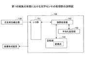
次に、第1の実施の形態における光学センサについて説明する。図9に本実施の形態における光学センサを示す。本実施の形態における光学センサは、光源110、光源110から出射された光を集光するレンズ120、記録紙20に正反射された光を検出する正反射光検出器130、正反射光検出器130の前に設置されるアパーチャー板170を有している。光源110はLED(Light Emitting Diode)等により形成されており、光源110より出射された光はレンズ120を介し、記録紙20に照射される。記録紙20に照射された光は、記録紙20において反射される。正反射光検出器130は、フォトダイオード等により形成されており、記録紙20において反射された光のうち正反射された光を検出する。アパーチャー板170には開口部171が形成されており、アパーチャー板170における開口部171を通過した光のみを正反射光検出器130に入射させることができる。即ち、アパーチャー板170を用いることにより、正反射光検出器130に所定の角度の光を入射させることができる。尚、記録紙20に入射する光の角度θ11、即ち、記録紙20の表面の法線に対し、光源110と記録紙20における照射エリア中心とを結んだ光軸の角度(入射角)θ11は、80°とした。また、正反射光検出器130には処理部150が接続されており、光学センサの制御及び各種演算等を行う。
(Optical sensor)
Next, the optical sensor in the first embodiment will be described. FIG. 9 shows an optical sensor in the present embodiment. The optical sensor according to the present embodiment includes a
尚、本実施の形態における光学センサは、底面側に開口部161を有する筐体160を有しており、光源110、レンズ120、正反射光検出器130、アパーチャー板170等は、筐体160内に設置されている。また、記録紙20の表面の法線に対し、記録紙20における照射エリア中心と正反射光検出器130とを結んだ光軸の角度(検出角)θ12とする。尚、本実施の形態においては、光源110の位置で定まる入射角θ11とアパーチャー板170における開口部171及び正反射光検出器130の位置により定まる検出角θ12は等しく80°とした。
Note that the optical sensor in this embodiment includes a
本実施の形態においては、記録紙20には、精度のよい平行光が照射されることが好ましいことから、レンズ120が設けられている。レンズ120は、例えば、焦点距離f=9mm、直径2mmφのものが用いられており、レンズ120の焦点位置に、光源110となるLEDの発光点が位置するように配置されている。
In the present embodiment, since the
正反射光検出器130についても、光源110の場合と同様に筐体160内に固定されている。本実施の形態においては、正反射光検出器130には、フォトダイオード(PD)が用いられている。用いられたPDは、大きさが5mm角程度あり、受光面となる光検出面が3mm角のものである。
The specular
図10に示されるように、アパーチャー板170に形成される開口部171の形状は、一方の辺の長さが(Aa1+Ab1)、他方の辺の長さが2×Ac1となる矩形状に形成されている。尚、開口部171は、容易に加工することができるよう、矩形状で形成されている。Aa1は光軸中心より角度が小さい側における距離であり、Ab1は光軸中心より角度が大きい側における距離であり、Ac1はAa1及びAb1における方向に対し垂直となる方向における光軸中心からの距離である。ここで、Laを16mmとした場合、θa1が7.8°、θa2が2.2°となるように、アパーチャー板170における開口部171を形成すると、Aa1は約4.8mm、Ab1は約1.2mmとなる。また、Ac1は約3.0mmとなるように形成されている。このように、記録紙20における照射エリアの中心と、アパーチャー板170の開口部171の中心とを結んだ角度は、光軸中心となる角度よりも小さくなる。尚、Ac1は横方向の散乱光の取り込みを規制しているものであり、一般的なランバート分布を想定しており、Ac1は取り込み全角度幅が10°(±5°)として算出した。
As shown in FIG. 10, the shape of the
(記録紙20の位置)
本実施の形態における光学センサにおいて検出される対象物は記録紙20である。記録紙20は、例えば、不図示の搬送ローラによって搬送され、ガイドにそって移動する。このため、本実施の形態における光学センサと記録紙20との距離は、常に一定になるように制御されている。
(Position of recording paper 20)
The object detected by the optical sensor in the present embodiment is the
(筐体160)
本実施の形態における光学センサは、前述したように、光源110、レンズ120、正反射光検出器130等が、筐体160内に納められている。本実施の形態における光学センサでは、筐体160の開口部161より記録紙20に光を照射し、照射された光の記録紙20からの正反射光を正反射光検出器130において受光する構造となっている。筐体160は、光を吸収する黒色のABS樹脂等により形成されており、筐体160によって、外乱光は除去される。筐体160の内部には、光源110、レンズ120、正反射光検出器130等を固定して設置することができるように形成されている。
(Housing 160)
In the optical sensor according to the present embodiment, as described above, the
(処理部150)
次に、本実施の形態における光学センサの処理部150について説明する。図11に示されるように、処理部150は光学センサの正反射光検出器130等と接続されている。また、処理部150は、正反射光検出器130等からの信号の入出力制御を行うI/O部151、信号処理等の各種演算を行う演算処理部152、平均化処理等を行う平均化処理部153、各種情報が記憶されている記憶部154を有している。また、本実施の形態における光学センサは、処理部150を介し画像形成装置等に接続されている。
(Processing unit 150)
Next, the
(光学センサによる検出方法等)
次に、本実施の形態における光学センサによる検出方法等を図12に基づき説明する。
(Detection method using an optical sensor, etc.)
Next, a detection method using the optical sensor in this embodiment will be described with reference to FIG.
最初に、ステップ102(S102)に示すように、本実施の形態における光学センサを用いた反射光強度検出操作を開始する。具体的には、電源をオンにする操作、または、本実施の形態における光学センサに接続されている画像形成装置に印刷の開始を知らせる信号が送られることにより、本実施の形態における光学センサを用いた反射光強度検出操作を開始する。 First, as shown in step 102 (S102), the reflected light intensity detection operation using the optical sensor in the present embodiment is started. Specifically, the operation of turning on the power or a signal notifying the start of printing is sent to the image forming apparatus connected to the optical sensor in the present embodiment, whereby the optical sensor in the present embodiment is changed. The reflected light intensity detection operation used is started.
次に、ステップ104(S104)に示すように、記録紙20が搬送される。このように記録紙20が搬送させることにより、光源110から出射された光はレンズ120を介し、搬送された記録紙20に照射され、記録紙20における正反射光が、正反射光検出器130に入射する。尚、記録紙20が搬送されている状態において、記録紙20に光を照射し、記録紙20において正反射光を検出することにより、記録紙20の一方の端から他方の端までの正反射光を検出することができる。
Next, as shown in step 104 (S104), the
次に、ステップ106(S106)に示すように、記録紙20における反射光強度検出が終了し、測定結果が処理部150に伝達される。
Next, as shown in step 106 (S106), the reflected light intensity detection on the
次に、ステップ108(S108)に示すように、処理部150において、正反射光検出器130において検出された光強度を平均化する処理を行う。この平均化する処理は、処理部150における平均化処理部153において行なわれる。
Next, as shown in step 108 (S108), the
次に、ステップ110(S110)に示すように、処理部150において、平均化処理された光強度に基づき平滑度を算出する。具体的には、処理部150における演算処理部152において、処理部150における記憶部154に記憶されている所定の変換式に基づき、光強度から平滑度を算出する。例えば、正反射光検出器130により検出された正反射光の強度をX(mV)とした場合に、平滑度Y(sec)は、Y=0.46×X+19.8となる変換式に基づき平滑度を算出することができる。
Next, as shown in step 110 (S110), the
次に、ステップ112(S112)に示すように、処理部150において、算出された平滑度に基づき、画像形成装置において記録紙20に印刷を行う際の定着時の作像プロセス条件を決定する。具体的には、処理部150における記憶部154に記憶されている図13に示す平滑度と印刷条件との関係に基づき、算出された平滑度に最も近い条件を定着時の作像プロセス条件として決定する。
Next, as shown in step 112 (S112), in the
次に、ステップ114(S114)に示すように、画像形成装置において記録紙20に印刷が行なわれ、記録紙20に画像が形成される。
Next, as shown in step 114 (S114), printing is performed on the
以上により、本実施の形態における光学センサを用いて平滑度を検出することができ、検出された平滑度に基づき画像形成装置の印刷条件を設定することができる。 As described above, the smoothness can be detected using the optical sensor according to the present embodiment, and the printing conditions of the image forming apparatus can be set based on the detected smoothness.
〔第2の実施の形態〕
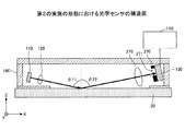
次に、第2の実施の形態について説明する。本実施の形態は、図14に示すように、記録紙20とアパーチャー板270との間に、レンズ221を設けた構造のものである。これにより、記録紙20の側より、レンズ221、アパーチャー板270、正反射光検出器130の順に設置される。レンズ221は、例えば、第1の実施の形態において、アパーチャー板170が設置されている位置に設けられている。このように、レンズ221を設けることにより、記録紙20からの反射光を平行光にすることや、集光することができ、正反射光検出器130に入射する光の光量を増やすことができる。尚、アパーチャー板270には、開口部271が形成されている。
[Second Embodiment]
Next, a second embodiment will be described. In this embodiment, as shown in FIG. 14, a
レンズ221は、平行光を正反射光検出器130に集光する機能を有している。これは理想的に正反射光検出器130の面積が小さい場合には、ほぼ平行光のみしか集光できない。これに対し、正反射光検出器130が有限の有効径である場合には、平行光から若干ずれた光も集光することができるようになる。本願においては、この平行光からずれた角度を光の取り込み角度と記載する。光の取り込み全角度幅は、正反射光検出器130における受光面の面積と、レンズ221のNA値に依存する。光の取り込み全角度幅が大きいと、検出角θ22の幅が広がり、誤差が生じてしまう。以下ではレンズを利用して取り込み角を制限する具体的な方法を記す。
The
レンズ221は、図14に示されるように、記録紙20と正反射光検出器130との間において、正反射(θ11=θ22)の光線を中心にした光軸の中心に配置する。レンズ221は、f値に合わせて、例えば、正反射光検出器130は、受光領域131が焦点位置の前後、または焦点位置となるように配置する。本実施の形態における説明においては、正反射光検出器130は、レンズ221の焦点位置の前になるように設置した場合について説明する。
As shown in FIG. 14, the
図15に示されるように、レンズ221の上側の端部近傍に入射角φs1で入射する光、及び、レンズ221の下側の端部近傍に入射角φs2で入射する光は、レンズ221により集光され、アパーチャー板270に入射する。アパーチャー板270に入射した光のうち、アパーチャー板270の開口部271を通過した光が、正反射光検出器130の受光領域131に入射する。これにより、正反射光検出器130に入射する光の光量を増やすことや、受光領域131の小さな正反射光検出器130を用いることができる。本実施の形態においては、例えば、入射角φs1が7.8°、入射角φs2が2.2°となるように、レンズ221、アパーチャー板270、正反射光検出器130の位置が調整されている。このように、本実施の形態においては、記録紙20における照射エリアの中心と、レンズ221の中心とを結んだ角度は、光軸中心となる角度よりも小さくなる。
As shown in FIG. 15, light incident at an
図16に示されるように、アパーチャー板270における開口部271の形状は、入射角φs1に対応した光軸中心からの距離がRa、入射角φs2に対応した光軸中心からの距離がRbとなるように形成されている。また、距離Ra及び距離Rbにおける方向に対し垂直となる方向における距離がRcとなるように形成されている。尚、距離Raは、光軸中心より角度が小さい側における距離であり、距離Abは、光軸中心より角度が大きい側における距離である。また、記録紙20における光の散乱は、横方向に関して、一般的なランバート分布をしているため、図5に示される結果に基づき、距離Rcは取り込み全角度幅が10°(±5°)に対応する長さとなるように形成されている。
As shown in FIG. 16, the shape of the
尚、本実施の形態においては、レンズ221と正反射光検出器130の位置が調整されていれば、アパーチャー板270が設けられていなくともよい。
In the present embodiment, the
このように、本実施の形態においては、レンズ221が設けられているため、記録紙20からの反射光を無駄なく正反射光検出器130に入射させることができ、SN比を向上させ、検出精度を向上させることができる。
Thus, in the present embodiment, since the
尚、上記以外の内容については、第1の実施の形態と同様である。 The contents other than the above are the same as in the first embodiment.
〔第3の実施の形態〕
次に、第3の実施の形態について説明する。本実施の形態は、図17及び図18に示されるように、正反射光検出器130の位置を調整し設置したものである。これにより、本実施の形態においては、アパーチャー板等を設ける必要がなくなる。
[Third Embodiment]
Next, a third embodiment will be described. In this embodiment, as shown in FIGS. 17 and 18, the position of the regular
前述したように、図3に示されるように、普通紙3B及び3Cに示される平滑度の低い紙の場合に、高い光強度を示す角度が正反射の位置から5°程度ずれる。このため、正反射光検出器130における受光領域131を受光角の小さい側に移動させる。具体的には、入射角θ11が80°、受光角θ23が74°となるように、正反射光検出器130を設置する。
As described above, as shown in FIG. 3, in the case of the low smoothness paper shown in the plain papers 3B and 3C, the angle indicating the high light intensity is shifted by about 5 ° from the position of the regular reflection. For this reason, the
尚、上記以外の内容については、第1の実施の形態と同様である。 The contents other than the above are the same as in the first embodiment.
〔第4の実施の形態〕
次に、第4の実施の形態について説明する。本実施の形態は、画像形成装置である。図19に基づき本実施の形態における画像形成装置としてのカラープリンタ2000について説明する。
[Fourth Embodiment]
Next, a fourth embodiment will be described. The present embodiment is an image forming apparatus. A
このカラープリンタ2000は、4色(ブラック、シアン、マゼンタ、イエロー)を重ね合わせてフルカラーの画像を形成するタンデム方式の多色カラープリンタであり、光走査装置2010、4つの感光体ドラム(2030a、2030b、2030c、2030d)、4つのクリーニングユニット(2031a、2031b、2031c、2031d)、4つの帯電装置(2032a、2032b、2032c、2032d)、4つの現像ローラ(2033a、2033b、2033c、2033d)、4つのトナーカートリッジ(2034a、2034b、2034c、2034d)、転写ベルト2040、転写ローラ2042、定着装置2050、給紙コロ2054、レジストローラ対2056、排紙ローラ2058、給紙トレイ2060、排紙トレイ2070、通信制御装置2080、光学センサ2245、及び上記各部を統括的に制御するプリンタ制御装置2090などを備えている。通信制御装置2080は、ネットワークなどを介した上位装置(例えばパソコン)との双方向の通信を制御する。
The
プリンタ制御装置2090は、CPU、このCPUにて解読可能なコードで記述されたプログラム及びこのプログラムを実行する際に用いられる各種データが格納されているROM、作業用のメモリであるRAM、アナログデータをデジタルデータに変換するAD変換回路などを有している。そして、プリンタ制御装置2090は、上位装置からの要求に応じて各部を制御するとともに、上位装置からの画像情報を光走査装置2010に送る。
感光体ドラム2030a、帯電装置2032a、現像ローラ2033a、トナーカートリッジ2034a、及びクリーニングユニット2031aは、組として使用され、ブラックの画像を形成する画像形成ステーション(以下では、便宜上「Kステーション」ともいう)を構成する。
The
The
感光体ドラム2030b、帯電装置2032b、現像ローラ2033b、トナーカートリッジ2034b、及びクリーニングユニット2031bは、組として使用され、シアンの画像を形成する画像形成ステーション(以下では、便宜上「Cステーション」ともいう)を構成する。
The
感光体ドラム2030c、帯電装置2032c、現像ローラ2033c、トナーカートリッジ2034c、及びクリーニングユニット2031cは、組として使用され、マゼンタの画像を形成する画像形成ステーション(以下では、便宜上「Mステーション」ともいう)を構成する。
The
感光体ドラム2030d、帯電装置2032d、現像ローラ2033d、トナーカートリッジ2034d、及びクリーニングユニット2031dは、組として使用され、イエローの画像を形成する画像形成ステーション(以下では、便宜上「Yステーション」ともいう)を構成する。
The
各感光体ドラムはいずれも、その表面に感光層が形成されている。すなわち、各感光体ドラムの表面がそれぞれ被走査面である。なお、各感光体ドラムは、不図示の回転機構により、図19における面内で矢印方向に回転するものとする。各帯電装置は、対応する感光体ドラムの表面をそれぞれ均一に帯電させる。 Each photosensitive drum has a photosensitive layer formed on the surface thereof. That is, the surface of each photoconductive drum is a surface to be scanned. Each photosensitive drum is rotated in the direction of the arrow in the plane of FIG. 19 by a rotation mechanism (not shown). Each charging device uniformly charges the surface of the corresponding photosensitive drum.
光走査装置2010は、上位装置からの多色の画像情報(ブラック画像情報、シアン画像情報、マゼンタ画像情報、イエロー画像情報)に基づいて、各色毎に変調された光束を、対応する帯電された感光体ドラムの表面にそれぞれ照射する。これにより、各感光体ドラムの表面では、光が照射された部分だけ電荷が消失し、画像情報に対応した潜像が各感光体ドラムの表面にそれぞれ形成される。ここで形成された潜像は、感光体ドラムの回転に伴って対応する現像ローラの方向に移動する。
Based on the multicolor image information (black image information, cyan image information, magenta image information, yellow image information) from the higher-level device, the
トナーカートリッジ2034aにはブラックトナーが格納されており、ブラックトナーは現像ローラ2033aに供給される。トナーカートリッジ2034bにはシアントナーが格納されており、シアントナーは現像ローラ2033bに供給される。トナーカートリッジ2034cにはマゼンタトナーが格納されており、マゼンタトナーは現像ローラ2033cに供給される。トナーカートリッジ2034dにはイエロートナーが格納されており、イエロートナーは現像ローラ2033dに供給される。
The
各現像ローラは、回転に伴って、対応するトナーカートリッジからのトナーが、その表面に薄く均一に塗布される。そして、各現像ローラの表面のトナーは、対応する感光体ドラムの表面に接すると、現像ローラの表面における光が照射された部分にだけ移行し、そこに付着する。すなわち、各現像ローラは、対応する感光体ドラムの表面に形成された潜像にトナーを付着させて顕像化させる。ここでトナーが付着した像(トナー画像)は、感光体ドラムの回転に伴って転写ベルト2040の方向に移動する。
As each developing roller rotates, the toner from the corresponding toner cartridge is thinly and uniformly applied to the surface thereof. Then, when the toner on the surface of each developing roller comes into contact with the surface of the corresponding photosensitive drum, the toner moves only to a portion irradiated with light on the surface of the developing roller and adheres thereto. In other words, each developing roller causes toner to adhere to the latent image formed on the surface of the corresponding photosensitive drum so as to be visualized. Here, the toner-attached image (toner image) moves in the direction of the
イエロー、マゼンタ、シアン、ブラックの各トナー画像は、所定のタイミングで転写ベルト2040上に順次転写され、重ね合わされて多色のカラー画像が形成される。
The yellow, magenta, cyan, and black toner images are sequentially transferred onto the
給紙トレイ2060には記録紙が格納されている。この給紙トレイ2060の近傍には給紙コロ2054が配置されており、給紙コロ2054は、記録紙を給紙トレイ2060から1枚ずつ取り出し、レジストローラ対2056に搬送する。レジストローラ対2056は、所定のタイミングで記録紙を転写ベルト2040と転写ローラ2042との間隙に向けて送り出す。これにより、転写ベルト2040上のカラー画像が記録紙に転写される。ここで転写された記録紙は、定着装置2050に送られる。
Recording paper is stored in the
定着装置2050では、熱と圧力とが記録紙に加えられ、これによってトナーが記録紙上に定着される。ここで定着された記録紙は、排紙ローラ2058を介して排紙トレイ2070に送られ、排紙トレイ2070上に順次スタックされる。
In the
各クリーニングユニットは、対応する感光体ドラムの表面に残ったトナー(残留トナー)を除去する。残留トナーが除去された感光体ドラムの表面は、再度対応する帯電装置に対向する位置に戻る。 Each cleaning unit removes toner (residual toner) remaining on the surface of the corresponding photosensitive drum. The surface of the photosensitive drum from which the residual toner has been removed returns to the position facing the corresponding charging device again.
光学センサ2245は、給紙トレイ2060内に収容されている記録紙の平滑度を検出するのに用いられる。この光学センサ2245は、光学センサ2245は、第1から第3の実施の形態における光学センサのうちのいずれかを用いる。
The
これらの光学センサにおいては、筐体160は、樹脂製の箱部材、例えば、ABS製の箱部材であり、外乱光及び迷光の影響を低減するため、表面は黒色処理が施されている。尚、ここでは、XYZ3次元直交座標系において、記録紙の表面に直交する方向をZ軸方向、記録紙の表面に平行な面をXY面として説明する。そして、光学センサ2245は、記録紙の+Z側に配置されているものとする。
In these optical sensors, the
また、カラープリンタ2000が対応可能な複数銘柄の記録紙に関して、予め調整工程等の出荷前工程で記録紙の平滑度に各ステーションでの最適な現像条件及び転写条件を決定されている。この決定結果は「現像・転写テーブル」としてプリンタ制御装置2090のROMに格納されている。
In addition, regarding a plurality of brands of recording paper that can be handled by the
プリンタ制御装置2090は、カラープリンタ2000の電源が入れられたとき、及び給紙トレイ2060に記録紙が供給されたときなどに、記録紙の平滑度検知処理を行う。
The
プリンタ制御装置2090は、ユーザからの印刷ジョブ要求を受け取ると、記録紙の平滑度に最適な現像条件及び転写条件を、RAMに保存されている現像・転写テーブルから求める。そして、プリンタ制御装置2090は、最適な現像条件及び転写条件に応じて各ステーションの現像装置及び転写装置を制御する。例えば、転写電圧やトナー量を制御する。これにより、高い品質の画像が記録紙に形成される。
Upon receiving a print job request from the user, the
本実施の形態においては、記録紙の平滑度を検出することができるため、記録紙の平滑度に最適な定着条件を設定することができ、低消費電力の画像形成装置を提供できる。 In the present embodiment, since the smoothness of the recording paper can be detected, an optimum fixing condition can be set for the smoothness of the recording paper, and an image forming apparatus with low power consumption can be provided.
また、上記実施形態では、給紙トレイが1つの場合について説明したが、これに限定されるものではなく、給紙トレイが複数あってもよい。この場合は、給紙トレイ毎に光学センサ2245を設けてもよい。
In the above embodiment, the case where there is one paper feed tray has been described. However, the present invention is not limited to this, and a plurality of paper feed trays may be provided. In this case, an
また、上記実施形態において、搬送中に記録紙の銘柄を特定してもよい。この場合は、光学センサ2245は搬送路近傍に配置される。例えば、光学センサ2245を、前記給紙コロ2054と前記レジストローラ対2056の間の搬送路近傍に配置してもよい。また、光学センサ2245によって識別される対象物は、記録紙に限定されるものではない。
In the above embodiment, the brand of the recording paper may be specified during conveyance. In this case, the
なお、上記実施形態では、画像形成装置としてカラープリンタ2000の場合について説明したが、これに限定されるものではなく、例えば、光プロッタやデジタル複写装置であってもよい。
In the above embodiment, the
また、上記実施形態では、画像形成装置が4つの感光体ドラムを有する場合について説明したが、これに限定されるものではない。 In the above embodiment, the case where the image forming apparatus has four photosensitive drums has been described. However, the present invention is not limited to this.
また、光学センサ2245は、記録紙にインクを吹き付けて画像を形成する画像形成装置にも適用可能である。
The
また、上述した実施の形態における光学センサによって識別される対象物は、記録紙に限定されるものではない。 Further, the object identified by the optical sensor in the above-described embodiment is not limited to recording paper.
以上、本発明の実施に係る形態について説明したが、上記内容は、発明の内容を限定するものではない。 As mentioned above, although the form which concerns on implementation of this invention was demonstrated, the said content does not limit the content of invention.
10 光源
20 記録紙
30 正反射光検出器
70 アパーチャー板
71 開口部
110 光源
120 レンズ
130 正反射光検出器
131 受光領域
150 処理部
151 I/O部
152 演算処理部
153 平均化処理部
154 記憶部
160 筐体
170 アパーチャー板
171 開口部
221 レンズ
270 アパーチャー板
271 開口部
DESCRIPTION OF
Claims (6)
前記光源より出射された光を記録媒体に照射し、前記記録媒体における正反射光の強度を検出する光検出器と、
を有し、
前記記録媒体の表面の法線に対し、前記光源と前記記録媒体上に形成される照射エリア中心とを結んだ光軸の角度θ1は、75°≦θ1≦85°であって、
前記記録媒体の表面の法線に対し、前記記録媒体上に形成される照射エリア中心と前記光検出器とを結んだ光軸の角度θ2を角度θ1と同じとし、前記角度θ2よりも角度が小さい側の広がり角をθx1とし、前記角度θ2よりも角度が大きい側の広がり角をθx2とし、
前記記録媒体の表面の法線に対し、前記記録媒体上の照射エリアにおいて反射された反射光のうち、前記光検出器に入射する光の角度θとした場合、
|θx1|>|θx2|
θx1+θ1<θ<θx2+θ1
を満たすものであって、
取り込み全角度幅となる|θx1|+|θx2|は、5°≦|θx1|+|θx2|≦15°であることを特徴とする光学センサ。 A light source;
A photodetector for irradiating the recording medium with light emitted from the light source and detecting the intensity of specularly reflected light in the recording medium ;
Have,
The angle θ1 of the optical axis connecting the light source and the center of the irradiation area formed on the recording medium with respect to the normal of the surface of the recording medium is 75 ° ≦ θ1 ≦ 85 ° ,
The angle θ2 of the optical axis connecting the center of the irradiation area formed on the recording medium and the photodetector is the same as the angle θ1 with respect to the normal of the surface of the recording medium, and the angle is larger than the angle θ2. The spread angle on the small side is θx1, the spread angle on the side larger than the angle θ2 is θx2,
Of the reflected light reflected in the irradiated area on the recording medium with respect to the normal of the surface of the recording medium, the angle θ of the light incident on the photodetector,
| Θx1 |> | θx2 |
θx1 + θ1 <θ <θx2 + θ1
It der to satisfy the,
The incorporation full angular width | θx1 | + | θx2 | is, 5 ° ≦ | θx1 | + | θx2 | optical sensor, characterized in ≦ 15 ° der Rukoto.
前記アパーチャー板における開口部は、前記角度θ2を光軸中心とし、前記角度θ2よりも角度が小さい側の前記光軸中心からの距離をAa1とし、前記角度θ2よりも角度が大きい側の前記光軸中心からの距離をAb1とした場合に、
Aa1>Ab1
となるように設置されていることを特徴とする請求項1に記載の光学センサ。 Between the recording medium and the photodetector, an aperture plate having an opening is provided,
The aperture in the aperture plate has the angle θ2 as the optical axis center, the distance from the optical axis center on the side smaller than the angle θ2 as Aa1, and the light on the side larger in the angle θ2 When the distance from the axis center is Ab1,
Aa1> Ab1
The optical sensor according to claim 1, wherein the optical sensor is installed to be
前記記録媒体の表面の法線に対し、前記記録媒体上に形成される照射エリア中心と前記アパーチャー板における前記開口部の中心とを結んだ光軸の角度は、前記角度θ1よりも小さくなるように、前記アパーチャー板が設置されていることを特徴とする請求項1または2に記載の光学センサ。 Between the recording medium and the photodetector, an aperture plate having an opening is provided,
The angle of the optical axis connecting the center of the irradiation area formed on the recording medium and the center of the opening in the aperture plate with respect to the normal of the surface of the recording medium is smaller than the angle θ1. The optical sensor according to claim 1, wherein the aperture plate is installed.
前記記録媒体の表面の法線に対し、前記記録媒体上に形成される照射エリア中心と前記レンズの中心とを結んだ光軸の角度は、前記角度θ1よりも小さくなるように、前記レンズが設置されていることを特徴とする請求項1から3のいずれかに記載の光学センサ。 A lens is provided between the recording medium and the photodetector,
The angle of the optical axis connecting the center of the irradiation area formed on the recording medium and the center of the lens with respect to the normal of the surface of the recording medium is smaller than the angle θ1. The optical sensor according to claim 1, wherein the optical sensor is installed.
前記光検出器において検出された光の強度に基づき、前記記録媒体の平滑度を検出することを特徴とする請求項1から4のいずれかに記載の光学センサ。 The recording medium is paper,
5. The optical sensor according to claim 1, wherein the smoothness of the recording medium is detected based on the intensity of light detected by the photodetector. 6.
前記1から5のいずれかに記載の光学センサを有することを特徴とする画像形成装置。 In an image forming apparatus for forming an image on the recording medium,
An image forming apparatus comprising the optical sensor according to any one of 1 to 5 above.
Priority Applications (1)
| Application Number | Priority Date | Filing Date | Title |
|---|---|---|---|
| JP2017149720A JP6380629B2 (en) | 2017-08-02 | 2017-08-02 | Optical sensor and image forming apparatus |
Applications Claiming Priority (1)
| Application Number | Priority Date | Filing Date | Title |
|---|---|---|---|
| JP2017149720A JP6380629B2 (en) | 2017-08-02 | 2017-08-02 | Optical sensor and image forming apparatus |
Related Parent Applications (1)
| Application Number | Title | Priority Date | Filing Date |
|---|---|---|---|
| JP2013043115A Division JP2014169972A (en) | 2013-03-05 | 2013-03-05 | Optical sensor and image forming apparatus |
Related Child Applications (1)
| Application Number | Title | Priority Date | Filing Date |
|---|---|---|---|
| JP2018145811A Division JP6741048B2 (en) | 2018-08-02 | 2018-08-02 | Optical sensor and image forming apparatus |
Publications (3)
| Publication Number | Publication Date |
|---|---|
| JP2017223692A JP2017223692A (en) | 2017-12-21 |
| JP2017223692A5 JP2017223692A5 (en) | 2018-03-22 |
| JP6380629B2 true JP6380629B2 (en) | 2018-08-29 |
Family
ID=60687984
Family Applications (1)
| Application Number | Title | Priority Date | Filing Date |
|---|---|---|---|
| JP2017149720A Active JP6380629B2 (en) | 2017-08-02 | 2017-08-02 | Optical sensor and image forming apparatus |
Country Status (1)
| Country | Link |
|---|---|
| JP (1) | JP6380629B2 (en) |
Cited By (1)
| Publication number | Priority date | Publication date | Assignee | Title |
|---|---|---|---|---|
| JP2019053046A (en) * | 2018-08-02 | 2019-04-04 | 株式会社リコー | Optical sensor and image forming apparatus |
Family Cites Families (5)
| Publication number | Priority date | Publication date | Assignee | Title |
|---|---|---|---|---|
| JPH09257443A (en) * | 1996-03-22 | 1997-10-03 | Mitsubishi Paper Mills Ltd | Online measuring method for substance surface property |
| US6914684B1 (en) * | 2001-07-05 | 2005-07-05 | Lexmark International, Inc. | Method and apparatus for detecting media type |
| JP3938184B2 (en) * | 2005-03-22 | 2007-06-27 | キヤノン株式会社 | Information processing method and apparatus |
| JP2007304492A (en) * | 2006-05-15 | 2007-11-22 | Ricoh Co Ltd | Image forming apparatus |
| JP5849412B2 (en) * | 2011-03-17 | 2016-01-27 | 株式会社リコー | Optical sensor and image forming apparatus |
-
2017
- 2017-08-02 JP JP2017149720A patent/JP6380629B2/en active Active
Cited By (1)
| Publication number | Priority date | Publication date | Assignee | Title |
|---|---|---|---|---|
| JP2019053046A (en) * | 2018-08-02 | 2019-04-04 | 株式会社リコー | Optical sensor and image forming apparatus |
Also Published As
| Publication number | Publication date |
|---|---|
| JP2017223692A (en) | 2017-12-21 |
Similar Documents
| Publication | Publication Date | Title |
|---|---|---|
| CN110058499B (en) | Optical sensor and image forming apparatus | |
| JP5849412B2 (en) | Optical sensor and image forming apparatus | |
| JP5787276B2 (en) | Moisture sensor, moisture detector, and image forming apparatus | |
| US9429513B2 (en) | Sensor apparatus and image forming apparatus incorporating same | |
| KR101510027B1 (en) | Optical sensor and image forming apparatus | |
| JP6288549B2 (en) | Optical sensor, image forming apparatus including the same, and apparatus and method for discriminating paper type | |
| JP5900726B2 (en) | Optical sensor, image forming apparatus, and discrimination method | |
| JP5999304B2 (en) | Optical sensor and image forming apparatus | |
| US9103717B2 (en) | Optical sensor and image forming apparatus configured to detect inside diffusely-reflected light | |
| JP2012208103A (en) | Optical sensor and image-forming device | |
| US10031457B2 (en) | Optical sensor, recording medium discrimination device, and image forming apparatus | |
| JP6380629B2 (en) | Optical sensor and image forming apparatus | |
| JP2014169972A (en) | Optical sensor and image forming apparatus | |
| JP6741048B2 (en) | Optical sensor and image forming apparatus | |
| JP2017096650A (en) | Detector, and image forming apparatus | |
| JP2016148521A (en) | Optical sensor and image forming apparatus | |
| JP6686287B2 (en) | Recording medium smoothness detecting apparatus and image forming apparatus | |
| JP7005884B2 (en) | Optical sensor, recording medium discrimination device, and image forming device | |
| JP6665546B2 (en) | Detection device and image forming device | |
| JP2017187431A (en) | Optical sensor and image formation device |
Legal Events
| Date | Code | Title | Description |
|---|---|---|---|
| A521 | Written amendment |
Free format text: JAPANESE INTERMEDIATE CODE: A523 Effective date: 20180206 |
|
| TRDD | Decision of grant or rejection written | ||
| A977 | Report on retrieval |
Free format text: JAPANESE INTERMEDIATE CODE: A971007 Effective date: 20180627 |
|
| A01 | Written decision to grant a patent or to grant a registration (utility model) |
Free format text: JAPANESE INTERMEDIATE CODE: A01 Effective date: 20180703 |
|
| A61 | First payment of annual fees (during grant procedure) |
Free format text: JAPANESE INTERMEDIATE CODE: A61 Effective date: 20180716 |
|
| R151 | Written notification of patent or utility model registration |
Ref document number: 6380629 Country of ref document: JP Free format text: JAPANESE INTERMEDIATE CODE: R151 |