JP6366542B2 - Radiation imaging apparatus, radiation imaging system, and irradiation start detection method - Google Patents
Radiation imaging apparatus, radiation imaging system, and irradiation start detection method Download PDFInfo
- Publication number
- JP6366542B2 JP6366542B2 JP2015122115A JP2015122115A JP6366542B2 JP 6366542 B2 JP6366542 B2 JP 6366542B2 JP 2015122115 A JP2015122115 A JP 2015122115A JP 2015122115 A JP2015122115 A JP 2015122115A JP 6366542 B2 JP6366542 B2 JP 6366542B2
- Authority
- JP
- Japan
- Prior art keywords
- radiation
- imaging apparatus
- value
- radiation imaging
- control unit
- Prior art date
- Legal status (The legal status is an assumption and is not a legal conclusion. Google has not performed a legal analysis and makes no representation as to the accuracy of the status listed.)
- Active
Links
- 230000005855 radiation Effects 0.000 title claims description 203
- 238000001514 detection method Methods 0.000 title claims description 133
- 238000003384 imaging method Methods 0.000 title claims description 71
- 238000000034 method Methods 0.000 claims description 36
- 238000005259 measurement Methods 0.000 claims description 35
- 230000010354 integration Effects 0.000 claims description 29
- 238000006243 chemical reaction Methods 0.000 claims description 17
- 230000008569 process Effects 0.000 claims description 14
- 238000012545 processing Methods 0.000 claims description 13
- 230000008859 change Effects 0.000 claims description 10
- 238000005513 bias potential Methods 0.000 claims description 4
- 230000004044 response Effects 0.000 claims description 4
- 230000035945 sensitivity Effects 0.000 claims description 4
- 230000009467 reduction Effects 0.000 claims description 2
- 238000009825 accumulation Methods 0.000 description 12
- 238000011156 evaluation Methods 0.000 description 10
- 238000004364 calculation method Methods 0.000 description 8
- 230000000875 corresponding effect Effects 0.000 description 8
- 230000003321 amplification Effects 0.000 description 7
- 238000012937 correction Methods 0.000 description 7
- 238000003199 nucleic acid amplification method Methods 0.000 description 7
- 239000000872 buffer Substances 0.000 description 6
- 238000005070 sampling Methods 0.000 description 6
- 239000003990 capacitor Substances 0.000 description 4
- 238000012544 monitoring process Methods 0.000 description 4
- 230000000052 comparative effect Effects 0.000 description 3
- 230000005540 biological transmission Effects 0.000 description 2
- 230000002596 correlated effect Effects 0.000 description 2
- 230000001186 cumulative effect Effects 0.000 description 2
- 238000012986 modification Methods 0.000 description 2
- 230000004048 modification Effects 0.000 description 2
- 230000003287 optical effect Effects 0.000 description 2
- 239000000758 substrate Substances 0.000 description 2
- 238000012935 Averaging Methods 0.000 description 1
- 229910021417 amorphous silicon Inorganic materials 0.000 description 1
- 238000001914 filtration Methods 0.000 description 1
- 239000011521 glass Substances 0.000 description 1
- 230000001678 irradiating effect Effects 0.000 description 1
- 238000001356 surgical procedure Methods 0.000 description 1
- 239000010409 thin film Substances 0.000 description 1
Images


Classifications
-
- H—ELECTRICITY
- H04—ELECTRIC COMMUNICATION TECHNIQUE
- H04N—PICTORIAL COMMUNICATION, e.g. TELEVISION
- H04N23/00—Cameras or camera modules comprising electronic image sensors; Control thereof
- H04N23/30—Cameras or camera modules comprising electronic image sensors; Control thereof for generating image signals from X-rays
-
- G—PHYSICS
- G01—MEASURING; TESTING
- G01T—MEASUREMENT OF NUCLEAR OR X-RADIATION
- G01T1/00—Measuring X-radiation, gamma radiation, corpuscular radiation, or cosmic radiation
- G01T1/16—Measuring radiation intensity
- G01T1/24—Measuring radiation intensity with semiconductor detectors
- G01T1/247—Detector read-out circuitry
-
- G—PHYSICS
- G01—MEASURING; TESTING
- G01T—MEASUREMENT OF NUCLEAR OR X-RADIATION
- G01T1/00—Measuring X-radiation, gamma radiation, corpuscular radiation, or cosmic radiation
- G01T1/29—Measurement performed on radiation beams, e.g. position or section of the beam; Measurement of spatial distribution of radiation
-
- A—HUMAN NECESSITIES
- A61—MEDICAL OR VETERINARY SCIENCE; HYGIENE
- A61B—DIAGNOSIS; SURGERY; IDENTIFICATION
- A61B6/00—Apparatus or devices for radiation diagnosis; Apparatus or devices for radiation diagnosis combined with radiation therapy equipment
- A61B6/42—Arrangements for detecting radiation specially adapted for radiation diagnosis
- A61B6/4208—Arrangements for detecting radiation specially adapted for radiation diagnosis characterised by using a particular type of detector
- A61B6/4233—Arrangements for detecting radiation specially adapted for radiation diagnosis characterised by using a particular type of detector using matrix detectors
-
- A—HUMAN NECESSITIES
- A61—MEDICAL OR VETERINARY SCIENCE; HYGIENE
- A61N—ELECTROTHERAPY; MAGNETOTHERAPY; RADIATION THERAPY; ULTRASOUND THERAPY
- A61N5/00—Radiation therapy
- A61N5/10—X-ray therapy; Gamma-ray therapy; Particle-irradiation therapy
- A61N5/1048—Monitoring, verifying, controlling systems and methods
-
- G—PHYSICS
- G01—MEASURING; TESTING
- G01T—MEASUREMENT OF NUCLEAR OR X-RADIATION
- G01T1/00—Measuring X-radiation, gamma radiation, corpuscular radiation, or cosmic radiation
- G01T1/16—Measuring radiation intensity
- G01T1/17—Circuit arrangements not adapted to a particular type of detector
-
- H—ELECTRICITY
- H04—ELECTRIC COMMUNICATION TECHNIQUE
- H04N—PICTORIAL COMMUNICATION, e.g. TELEVISION
- H04N5/00—Details of television systems
- H04N5/30—Transforming light or analogous information into electric information
- H04N5/32—Transforming X-rays
Landscapes
- Health & Medical Sciences (AREA)
- Life Sciences & Earth Sciences (AREA)
- Engineering & Computer Science (AREA)
- Physics & Mathematics (AREA)
- High Energy & Nuclear Physics (AREA)
- Molecular Biology (AREA)
- General Physics & Mathematics (AREA)
- Spectroscopy & Molecular Physics (AREA)
- Multimedia (AREA)
- Signal Processing (AREA)
- Biomedical Technology (AREA)
- Medical Informatics (AREA)
- General Health & Medical Sciences (AREA)
- Nuclear Medicine, Radiotherapy & Molecular Imaging (AREA)
- Veterinary Medicine (AREA)
- Pathology (AREA)
- Radiology & Medical Imaging (AREA)
- Public Health (AREA)
- Animal Behavior & Ethology (AREA)
- Surgery (AREA)
- Heart & Thoracic Surgery (AREA)
- Biophysics (AREA)
- Mathematical Physics (AREA)
- Optics & Photonics (AREA)
- Measurement Of Radiation (AREA)
- Apparatus For Radiation Diagnosis (AREA)
- Transforming Light Signals Into Electric Signals (AREA)
Description
本発明は、放射線撮像装置、放射線撮像システムおよび照射開始検出方法に関する。 The present invention relates to a radiation imaging apparatus, a radiation imaging system, and an irradiation start detection method.
X線等の放射線によって形成される光学像を電気的に撮像する放射線撮像装置がある。放射線撮像装置の方式は、放射線を直接に電気信号に変換する直接型と、放射線をシンチレータによって光に変換し、光を電気信号に変換する間接型とに大別される。いずれの方式においても、放射線の照射の開始に同期して放射線画像の撮像動作が実行される必要がある。同期の方式としては、放射線源の制御装置から放射線撮像装置に同期信号を送る方式と、放射線撮像装置がそれに照射された放射線を検出する方式とがある。特許文献1には、センサ部で発生した電荷に起因した電気信号に基づいて放射線の照射開始を検出する放射線画像撮影装置が記載されている。
There is a radiation imaging apparatus that electrically captures an optical image formed by radiation such as X-rays. The radiation imaging apparatus is roughly classified into a direct type that directly converts radiation into an electric signal and an indirect type that converts radiation into light by a scintillator and converts the light into an electric signal. In any of the methods, it is necessary to perform a radiographic image capturing operation in synchronization with the start of radiation irradiation. As a synchronization method, there are a method in which a synchronization signal is transmitted from the radiation source control device to the radiation imaging device, and a method in which the radiation imaging device detects radiation applied thereto.
放射線撮像装置がそれに照射された放射線を検出することによって放射線の照射の開始を検出する方式では、照射された放射線に感度を有する信号に含まれるノイズが大きいと、誤検出が発生しうる。 In the method in which the radiation imaging apparatus detects the start of radiation irradiation by detecting the radiation applied thereto, a false detection may occur if the noise included in the signal sensitive to the irradiated radiation is large.
本発明は、誤検出の防止ないし低減に有利な技術を提供することを目的とする。 An object of the present invention is to provide a technique advantageous for preventing or reducing false detection.
本発明の1つの側面は、放射線画像を撮像するために複数の画素を有する画素アレイと、放射線の照射を検出するための検出部と、制御部とを備える放射線撮像装置に係り、前記放射線撮像装置は、前記制御部は、前記検出部を使って得られる、基準値に対する変化分である測定値と、前記基準値に対して正および負のうちの一方における閾値と、の比較に基づく放射線の照射の開始の判定に応じて、前記画素アレイによる放射線画像の撮像動作を制御し、前記制御部は、前記正および前記負のうちの他方における前記測定値のみに応じて前記閾値を変更する。One aspect of the present invention relates to a radiation imaging apparatus including a pixel array having a plurality of pixels for capturing a radiation image, a detection unit for detecting radiation irradiation, and a control unit. In the apparatus, the control unit is a radiation based on a comparison between a measurement value obtained by using the detection unit, which is a change relative to a reference value, and a threshold value in one of positive and negative with respect to the reference value. In accordance with the determination of the start of irradiation, the imaging operation of the radiographic image by the pixel array is controlled, and the control unit changes the threshold only according to the measured value in the other of the positive and the negative .
本発明によれば、誤検出の防止ないし低減に有利な技術が提供される。 According to the present invention, a technique advantageous in preventing or reducing erroneous detection is provided.
以下、添付図面を参照しながら本発明をその例示的な実施形態を通して説明する。 Hereinafter, the present invention will be described through exemplary embodiments thereof with reference to the accompanying drawings.
[第1実施形態]
図1には、本発明の第1実施形態の放射線撮像システム200の構成が示されている。放射線撮像システム200は、放射線で形成される光学像を電気的に撮像し、電気的な放射線画像(即ち、放射線画像データ)を得るように構成されている。放射線は、典型的には、X線でありうるが、α線、β線、γ線などであってもよい。放射線撮像システム200は、例えば、放射線撮像装置210、放射線源230、曝射制御部220およびコンピュータ240を備えうる。放射線源230は、曝射制御部220からの曝射指令(放射指令)に従って放射線の放射を開始する。放射線源230から放射された放射線は、不図示の被険体を通って放射線撮像装置210に照射される。
[First Embodiment]
FIG. 1 shows a configuration of a
放射線撮像装置210は、放射線検出パネル212と、放射線検出パネル212を制御する制御部214とを含む。制御部214は、例えば、FPGA(Field Programmable Gate Arrayの略。)などのPLD(Programmable Logic Deviceの略。)、又は、ASIC(Application Specific Integrated Circuitの略。)、又は、プログラムが組み込まれた汎用コンピュータ、又は、これらの全部または一部の組み合わせによって構成されうる。制御部214は、サンプルホールド回路、オペアンプ等のアナログ回路を含んでもよい。
The
制御部214は、放射線検出パネル212を制御するほか、放射線検出パネル212から出力される信号を処理する。制御部214は、放射線検出パネル212から出力される検出信号の値または該検出信号を処理して得られる値である測定値が閾値を超えた場合に、放射線の照射が開始されたと判定し、放射線検出パネル212に放射線画像の撮像動作を開始させる。
The
図2には、放射線検出パネル212の構成例が示されている。放射線検出パネル212は、画素アレイ112を備えている。画素アレイ112は、放射線を検出する複数の画素PIX、および、複数の列信号線Sig(Sig1〜Sig3)を有する。なお、図2では、記載の簡単化のために、画素アレイ112は、3行×3列の画素PIXで構成されているが、実際には、より多くの画素PIXが配列されうる。一例において、放射線検出パネル212は、17インチの寸法を有し、約3000行×約3000列の画素PIXを有しうる。
FIG. 2 shows a configuration example of the
放射線検出パネル212はまた、画素アレイ112を駆動する駆動回路(行選択回路)114、および、画素アレイ112の複数の列信号線Sigに現れる信号を検出する読出部113と、放射線の照射を検出する検出部103を備えている。この例では、検出部103は、画素アレイ112を構成する複数の画素PIXの全部または一部に対してバイアス線Bs(導電線)を介してバイアス電位Vsを与えるバイアス回路を兼ねている。
The
バイアス回路を兼ねる検出部103は、差動増幅器121と、差動増幅器121の第1入力端子と差動増幅器121の出力端子との間に接続されたフィードバック抵抗122とを含みうる。差動増幅器121の第2入力端子には、バイアス電位Vs(所定値)が供給される。イマジナリーショートにより差動増幅器121の第1入力端子と第2入力端子とは同一電位となる。したがって、バイアス線Bsの電位は、差動増幅器121によってバイアス電位Vsに駆動される。差動増幅器121の出力端子には、バイアス線Bsを流れる電流、即ちバイアス線Bsに現れる電気信号に応じた電位が出力される。バイアス線Bsを流れる電流は、放射線の照射に対して感度を有する信号である。
The
放射線検出パネル212(画素アレイ112)に放射線が照射されると、それに応じた電流がバイアス線Bsを流れる。よって、差動増幅器121の出力端子には、画素アレイ112への放射線の照射量に相関がある電気信号が現れる。検出部103は、差動増幅器121の出力端子に出力される信号をA/D変換するA/D変換器123を含みうる。以下では、検出部103のA/D変換器123から出力される制御部214に供給される信号を検出信号と呼ぶが、差動増幅器121の出力端子に出力される信号を検出信号として理解することもできる。また、差動増幅器121とA/D変換器123との間には、増幅回路および/またはフィルタなどの回路が配置されてもよい。A/D変換器123は、制御部214に設けられてもよい。
When the radiation detection panel 212 (pixel array 112) is irradiated with radiation, a current corresponding to the radiation flows through the bias line Bs. Therefore, an electrical signal having a correlation with the radiation dose to the
検出部103は、バイアス線Bsを流れる電流を検出することによって画素アレイ112に対する放射線の照射を検出するが、これは一例である。画素アレイ112に対する放射線の照射は、列信号線Sigの電位または列信号線Sigを流れる電流を検出することによって検出されてもよい。あるいは、画素アレイ112に対する放射線の照射は、複数の画素PIXの一部から読出部113によって信号を読み出すことによって検出されてもよい。あるいは、画素アレイ112に対する放射線の照射は、画素アレイ112の中または画素アレイ112の外に専用の放射線検出センサを配置し、該放射線検出センサによって検出されてもよい。
The
各画素PIXは、放射線を検出する変換素子Cと、変換素子Cと列信号線Sig(複数の列信号線Sigのうち変換素子Cに対応する列信号線Sig)とを接続するスイッチSWとを含む。変換素子Cは、それに入射した放射線の量に対応する信号を列信号線Sigに出力する。変換素子Cは、例えば、ガラス基板等の絶縁性基板上に配置されアモルファスシリコンを主材料とするMIS型フォトダイオードを含みうる。あるいは、変換素子Cは、PIN型フォトダイオードを含みうる。変換素子Cは、放射線を直接に電気信号に変換する直接型として構成されてもよいし、放射線を光に変換した後に、光を検出する間接型として構成されてもよい。間接型においては、シンチレータが複数の画素PIXによって共有されうる。 Each pixel PIX includes a conversion element C that detects radiation, and a switch SW that connects the conversion element C and a column signal line Sig (a column signal line Sig corresponding to the conversion element C among the plurality of column signal lines Sig). Including. The conversion element C outputs a signal corresponding to the amount of radiation incident thereon to the column signal line Sig. The conversion element C can include, for example, a MIS photodiode that is disposed on an insulating substrate such as a glass substrate and mainly contains amorphous silicon. Alternatively, the conversion element C can include a PIN photodiode. The conversion element C may be configured as a direct type that directly converts radiation into an electric signal, or may be configured as an indirect type that detects light after converting the radiation into light. In the indirect type, the scintillator can be shared by a plurality of pixels PIX.
スイッチSWは、例えば、制御端子(ゲート)と2つの主端子(ソース、ドレイン)とを有する薄膜トランジスタ(TFT)などのトランジスタで構成されうる。変換素子Cは、2つの主電極を有し、変換素子Cの一方の主電極は、スイッチSWの2つの主端子のうちの一方に接続され、変換素子Cの他方の主電極は、バイアス線Bsに接続されている。第1行の画素PIXは、スイッチSWの制御端子がゲート線G1に接続され、第2行の画素PIXは、スイッチSWの制御端子がゲート線G2に接続され、第3行の画素PIXは、スイッチSWの制御端子がゲート線G3に接続されている。ゲート線G1、G2、G3・・・には、駆動回路114によってゲート信号Vg1、Vg2、Vg3・・・が供給される。 The switch SW can be constituted by a transistor such as a thin film transistor (TFT) having a control terminal (gate) and two main terminals (source, drain), for example. The conversion element C has two main electrodes, one main electrode of the conversion element C is connected to one of the two main terminals of the switch SW, and the other main electrode of the conversion element C is a bias line. Connected to Bs. The pixel PIX in the first row has the control terminal of the switch SW connected to the gate line G1, the pixel PIX in the second row has the control terminal of the switch SW connected to the gate line G2, and the pixel PIX in the third row A control terminal of the switch SW is connected to the gate line G3. Gate signals Vg1, Vg2, Vg3,... Are supplied to the gate lines G1, G2, G3,.
第1列の画素PIXは、スイッチSWの1つの主端子が第1列の列信号線Sig1に接続されている。第2列の画素PIXは、スイッチSWの1つの主端子が第2列の列信号線Sig2に接続されている。第3列の画素PIXは、スイッチSWの1つの主端子が第3列の列信号線Sig3に接続されている。各列信号線Sig(Sig1、Sig2、Sig3・・・)は、容量CCを有する。 In the first column pixel PIX, one main terminal of the switch SW is connected to the first column signal line Sig1. In the pixel PIX in the second column, one main terminal of the switch SW is connected to the column signal line Sig2 in the second column. In the pixel PIX in the third column, one main terminal of the switch SW is connected to the column signal line Sig3 in the third column. Each column signal line Sig (Sig1, Sig2, Sig3...) Has a capacitance CC.
読出部113は、1つの列信号線Sigに1つの列増幅部CAが対応するように複数の列増幅部CAを有する。各列増幅部CAは、例えば、積分増幅器105、可変増幅器104、サンプルホールド回路107、バッファ回路106を含みうる。積分増幅器105は、それに対応する列信号線Sigに現れた信号を増幅する。積分増幅器105は、例えば、演算増幅器と、該演算増幅器の反転入力端子と出力端子との間に並列に接続された積分容量およびリセットスイッチとを含みうる。該演算増幅器の非反転入力端子には、基準電位Vrefが供給される。該リセットスイッチは、制御部214によって駆動されるリセット信号RCが活性化されることによってオンし、これにより、該積分容量がリセットされるとともに列信号線Sigの電位が基準電位Vrefにリセットされる。
The reading unit 113 has a plurality of column amplification units CA so that one column amplification unit CA corresponds to one column signal line Sig. Each column amplification unit CA may include, for example, an
可変増幅器104は、積分増幅器105からの設定された増幅率で増幅する。サンプルホールド回路107は、制御部214によって駆動されるサンプルホールド信号SHが活性化されることによって可変増幅器104からの信号をサンプルホールドする。サンプルホールド回路107は、例えば、サンプリングスイッチとサンプリング容量とによって構成されうる。バッファ回路106は、サンプルホールド回路107からの信号をバッファリング(インピーダンス変換)して出力する。該サンプリングスイッチは、制御部214から供給されるサンプリングパルスによって制御されうる。
The
読出部113はまた、複数の列信号線Sigのそれぞれに対応するように設けられた複数の列増幅部CAからの信号を所定の順序で選択して出力するマルチプレクサ108を含む。マルチプレクサ108は、例えば、シフトレジスタを含み、該シフトレジスタは、制御部214から供給されるクロック信号に従ってシフト動作を行い、該シフトレジスタによって複数の列増幅部CAからの1つの信号が選択される。検出部103はまた、マルチプレクサ108から出力される信号をバッファリング(インピーダンス変換)するバッファ109、および、バッファ109から出力される信号であるアナログ信号をデジタル信号に変換するAD変換器110を含みうる。AD変換器110の出力、即ち、放射線画像データは、コンピュータ240に供給される。
The reading unit 113 also includes a
放射線撮像装置210の動作は、初期化動作、蓄積動作、読み出し動作を含む。初期化動作は、画素アレイ112の複数の画素PIXを行単位で初期化する動作である。蓄積動作は、画素アレイ112の各画素PIXにおいて放射線の照射によって発生する電荷を蓄積する動作である。読み出し動作は、画素アレイ112への放射線の照射によって画素アレイ112の各画素PIXに蓄積された電荷に応じた信号を画素アレイ112から読み出して画像(画像信号)として出力する動作である。
The operation of the
初期化動作から蓄積動作へは、検出部103から出力される検出信号に基づいて制御部214が放射線撮像装置210への放射線の照射が開始されたと判定することによって移行する。蓄積動作から読み出し動作へは、例えば、蓄積動作の開始から所定時間が経過したことに応じて移行する。
The initialization operation is transferred to the accumulation operation when the
図3および図4を参照しながら放射線撮像装置210の動作を説明する。制御部214は、ステップS310において、初期化動作を開始する。初期化動作では、制御部214は、第1行から最終行までのゲート線G(G1、G2、G3・・・)を順にアクティブレベルにするとともにリセット信号RCをアクティブレベルにする動作を繰り返す。ここで、リセット信号RCがアクティブレベルにされると、積分増幅器105はボルテージフォロワ状態となり、基準電位Vrefが信号線Sigに供給される。この状態で、駆動線Gがアクティブレベルにされた行のスイッチTが導通状態となり、変換素子201の容量Csに蓄積されていた電荷が初期化される。図4において、Vg(0)、Vg(1)、Vg(2)、・・・、Vg(Ys)、Vg(Ys+1)、・・・Vg(Y−1)は、画素アレイ112の第1行から最終行のゲート線Gに供給される駆動信号を示している。
The operation of the
初期化動作の期間において、検出部103は、画素アレイ112への放射線の照射量に相関のある検出信号を出力する。初期化動作中に、ステップS320において、制御部214は、放射線の照射が開始されたかどうかを判定する。具体的には、制御部214は、検出部103から出力される検出信号に基づいて、画素アレイ112への放射線の照射が開始されたかどうかを判定する。
In the period of the initialization operation, the
制御部214は、画素アレイ112への放射線の照射が開始されたと判定するまでは、初期化動作を継続する(ステップS370)。制御部214は、画素アレイ112への放射線の照射が開始されたと判定すると(ステップS320においてYES)、ステップS330において蓄積動作を開始する。即ち、放射線の照射の開始が検出されると(図4には、「照射開始検出」として示されている。)、初期化動作から蓄積動作に移行する。ステップS320における処理については後述する。
The
蓄積動作中は、制御部214は、ステップS340において、放射線の照射の終了を判定する。放射線の終了の判定方法は、特に限定されないが、例えば、蓄積動作の開始から所定時間が経過したことによって放射線の照射が終了したものと判定することができる。あるいは、制御部214は、検出部103から出力される検出信号の瞬間値、積分値および微分値の少なくとも1つに基づいて画素アレイ112への放射線の照射が終了したことを判定することができる。
During the accumulation operation, the
制御部214は、画素アレイ112への放射線の照射が終了したと判定するまでは、蓄積動作を継続する(ステップS380)。制御部214は、画素アレイ112への放射線の照射が終了したと判定すると(ステップS340においてYES)、ステップS350において、読み出し動作を開始する。即ち、放射線の照射が終了したと判定されると(図4には、「照射終了検出」として示されている。)、蓄積動作から読み出し動作に移行する。読み出し動作では、画素アレイ112の先頭行の画素から最終行の画素まで順番に信号が読み出される。
The
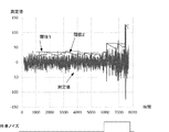
図5および図6には、比較例における放射線照射の開始の検出が示されている。図5は、制御部214が検出部103を使って得ることができる測定値にシステムノイズが含まれる場合の動作が示されている。図6には、制御部214が検出部103を使って得ることができる測定値にシステムノイズの他に外来ノイズが含まれる場合の動作が示されている。測定値は、放射線検出パネル212の検出部103から出力される検出信号の値、または、該検出信号を処理して得られる値である。ここで、検出部103から出力される検出信号を処理して得られる値は、例えば、制御部214が、検出部103から出力される検出信号を処理(例えば、増幅、フィルタリング、積分演算、移動平均演算など)して得られる値でありうる。あるいは、検出部103から出力される検出信号を処理して得られる値は、不図示の他のユニットが検出部103から出力される検出信号を処理して得られる値であってもよい。
5 and 6 show detection of the start of radiation irradiation in the comparative example. FIG. 5 shows an operation in the case where system noise is included in a measurement value that can be obtained by the
放射線撮像装置210に放射線が照射されると、バイアス線Bsに電流が流れる。検出部103を使って得られる測定値は、バイアス線Bsを流れる電流に相関を有する情報である。制御部214は、測定値が閾値を超えると、ステップS320において、放射線撮像装置210に対する放射線の照射が開始されたと判定する。ただし、測定値には、放射線撮像装置210に対する放射線の照射がない場合でも、ランダムなノイズが含まれる。このノイズがシステムノイズである。閾値は、例えば、システムノイズの標準偏差をσとしたときに、8σ以上に設定されうる。図5に例示されるように、外来ノイズが存在しない場合には、閾値をシステムノイズの8σ程度に設定すれば、放射線の照射の開始を問題なく検出することができる。
When the
しかしながら、図6に例示されるように外来ノイズが存在する場合には、その外来ノイズによって測定値が閾値を超えてしまい、放射線の照射が開始されていないにも拘わらず、放射線の照射が開始されたと判定されうる。これを誤検出と呼ぶ。誤検出が発生すると、蓄積動作(S330)に移行してしまい、再び初期化動作が開始されるまで放射線画像を撮像できない状態となる。この状態は、例えば、数秒程度になりうる。よって、誤検出が発生する放射線撮像装置は、使い勝手が悪い。一方、閾値を上げると、微弱な放射線を検出することができなくなる。医療の現場において、外来ノイズ原としては、以下のものが代表的であると考えられる。 However, when external noise exists as illustrated in FIG. 6, the measurement value exceeds the threshold due to the external noise, and radiation irradiation is started even though radiation irradiation has not started. It can be determined that This is called false detection. If an erroneous detection occurs, the process proceeds to an accumulation operation (S330), and a radiation image cannot be captured until the initialization operation is started again. This state can be, for example, several seconds. Therefore, the radiation imaging apparatus in which erroneous detection occurs is not easy to use. On the other hand, if the threshold value is increased, weak radiation cannot be detected. In the medical field, the following are considered as typical external noise sources.
・放射線撮像装置と電磁波を発生させる機器(例えば、ブラウン管(CRT)等)との接近、
・機器(例えば、放射線源)の電源のON/OFF
・モーター(例えば、手術用の電動ドリル、放射線源の回転陽極のためのモーター)の駆動
・強力な衝撃(例えば、衝突等)
例えば、放射線源の中には、スイッチが押されると、それに応答して放射線管球内の陽極が回転を始めるものがあり、この際に発生する電磁波によって測定値が閾値を超え、誤検出が起こりうる。このようなケースでは、誤検出の直後に放射線の照射が行われるため、正常な撮影が行われない可能性がある。
-The proximity of the radiation imaging device and a device (for example, a cathode ray tube (CRT)) that generates electromagnetic waves,
・ Power ON / OFF of equipment (for example, radiation source)
-Driving motors (eg motors for surgery, motors for rotating anodes of radiation sources)-Strong impacts (eg collisions, etc.)
For example, in some radiation sources, when the switch is pressed, the anode in the radiation tube starts rotating in response to this, and the measured value exceeds the threshold value due to the electromagnetic wave generated at this time, and false detection is performed. It can happen. In such a case, normal imaging may not be performed because radiation is irradiated immediately after erroneous detection.
以下、図7および図8を参照しながら、本発明の第1実施形態の放射線撮像装置210における放射線の照射の開始を検出する方法(照射開始検出方法)の原理を説明する。測定値、即ち、検出部103から出力される検出信号の値または該検出信号を処理して得られる値には、次のような特徴がある。
Hereinafter, the principle of a method for detecting the start of radiation irradiation (irradiation start detection method) in the
・放射線撮像装置に放射線が照射されたときに、測定値は、基準値に対して正の範囲および負の範囲のうちの一方の範囲において基準値との差分が大きくなるように変化する。 When the radiation imaging apparatus is irradiated with radiation, the measurement value changes so that a difference from the reference value becomes larger in one of a positive range and a negative range with respect to the reference value.
・外来ノイズが加わったときに、測定値は、基準値に対して正の範囲および負の範囲の双方で変化する。 • When extraneous noise is added, the measured value changes in both the positive and negative ranges with respect to the reference value.
・基準値に対して正の範囲における外来ノイズの波形と基準値に対して負の範囲における外来ノイズの波形とはほぼ対称である。 The external noise waveform in the positive range with respect to the reference value and the external noise waveform in the negative range with respect to the reference value are substantially symmetric.
ここで、基準値は、例えば0(ゼロ)である。また、システムノイズの平均値は、通常は0(ゼロ)である。図7および図8に示された例では、放射線撮像装置に放射線が照射されたときに、測定値は、基準値(0)に対して正の範囲において基準値との差分が大きくなるように変化する。これとは、逆に、放射線撮像装置に放射線が照射されたときに、測定値が基準値(0)に対して負の範囲において基準値との差分が大きくなるように検出部103または制御部214が構成されてもよい。
Here, the reference value is, for example, 0 (zero). Further, the average value of the system noise is normally 0 (zero). In the example shown in FIG. 7 and FIG. 8, when the radiation imaging apparatus is irradiated with radiation, the measured value has a difference from the reference value in a positive range with respect to the reference value (0). Change. Conversely, when the radiation imaging apparatus is irradiated with radiation, the
そこで、放射線の照射を受けたときに基準値に対して正の範囲および負の範囲のうちの一方において基準値に対する測定値の差分が大きくなる構成において、制御部214は、正の範囲および負の範囲のうちの他方における測定値に応じて閾値を変更する。例えば、放射線の照射を受けたときに基準値に対して正の範囲において測定値と基準値との差分が大きくなる構成において、制御部214は、負の範囲における測定値に応じて閾値を変更する。また、放射線の照射を受けたときに基準値に対して負の範囲において測定値と基準値との差分が大きくなる構成において、制御部214は、正の範囲における測定値に応じて閾値を変更する。
Therefore, in a configuration in which the difference between the measurement values with respect to the reference value increases in one of the positive range and the negative range with respect to the reference value when receiving radiation, the
ここで、「一方の範囲」を「監視範囲」、「他方の範囲」を「ノイズ評価範囲」と呼ぶことにする。制御部214は、ノイズ評価範囲における測定値に基づいて閾値を変更しながら、監視範囲における測定値が該閾値を越えた場合に、放射線が照射されたと判定する。図7および図8に示された例は、測定値が正の値を示す範囲が監視範囲であり、測定値が負の値を示す範囲がノイズ評価範囲である。
Here, “one range” is referred to as “monitoring range”, and “the other range” is referred to as “noise evaluation range”. The
一例において、制御部214は、ノイズ評価範囲における測定値の包絡線に基づいて測定値に含まれるノイズレベルを推定し、このノイズレベルに従って閾値を変更する。このような方式によれば、図7に例示されるように外来ノイズが加わることによって測定値が多くなっても、それに応じて閾値が大きくなるので、誤検出が発生しない。また、外来ノイズが加わらない場合には、図8に例示されるように、制御部214は、閾値を変更しない。したがって、外来ノイズが加わる場合も、外来ノイズが加わらない場合も、誤検出を防止しつつ、放射線の照射が開始されたことを正確に検出することができる。
In one example, the
以下、図9を参照しながら制御部214による閾値の変更の例を説明する。この例では、制御部214は、ノイズ評価範囲における測定値の最大値(包絡線)に基づいて測定値に含まれるノイズレベルを推定(決定)し、このノイズレベルに従って閾値を変更する。ここでは、ノイズレベルを推定する方法について、3つの例を説明する。
Hereinafter, an example of threshold value change by the
ノイズレベルを推定する第1の方法では、ノイズ評価範囲(図9では、測定値が負の範囲)における複数の測定値の振幅値(絶対値)の最大値を用いる。時刻tにおけるノイズ評価範囲内の測定値をV(t)、最大値を計算する区間をnとしたとき、時刻tにおけるノイズレベルA(t)は、(1)式で表される。 In the first method for estimating the noise level, the maximum value of the amplitude values (absolute values) of a plurality of measurement values in the noise evaluation range (in FIG. 9, the measurement value is a negative range) is used. When the measured value in the noise evaluation range at time t is V (t) and the interval for calculating the maximum value is n, the noise level A (t) at time t is expressed by equation (1).
A(t)=max{−V(t),−V(t−1),・・・,−V(t−n−1)}
・・・(1)
ノイズレベルを推定する第2の方法では、時刻tにおけるノイズ評価範囲内の測定値をV(t)、過去のノイズレベルをA(t−1)、一定値をα(α<1)としたとき、時刻tにおけるノイズレベルA(t)は、(2)式で表される。
A (t) = max {−V (t), −V (t−1),..., −V (tn−1)}
... (1)
In the second method for estimating the noise level, the measured value within the noise evaluation range at time t is V (t), the past noise level is A (t−1), and the constant value is α (α <1). At this time, the noise level A (t) at time t is expressed by equation (2).
A(t)=max{−V(t),A(t−1)*α}
・・・(2)
ノイズレベルを推定する第3の方法では、時刻tにおけるノイズ評価範囲内の測定値をV(t)、過去のノイズレベルをA(t−1)、一定値をβ(β>0)としたとき、時刻tにおけるノイズレベルA(t)は、(3)式で表される。
A (t) = max {−V (t), A (t−1) * α}
... (2)
In the third method for estimating the noise level, the measured value within the noise evaluation range at time t is V (t), the past noise level is A (t−1), and the constant value is β (β> 0). At this time, the noise level A (t) at time t is expressed by equation (3).
A(t)=max{−V(t),A(t−1)−β}
・・・(3)
ノイズレベルを推定(決定)する方法は、上記の第1、第2および第3の方法に限定されず、他の方法が採用されてもよい。
A (t) = max {−V (t), A (t−1) −β}
... (3)
The method for estimating (determining) the noise level is not limited to the first, second, and third methods described above, and other methods may be employed.
次に、制御部214が時刻tにおけるノイズレベルA(t)に基づいて時刻t+Δtにおける閾値T’(t+Δt)を決定する方法の例を説明する。ノイズレベルには、外来ノイズとシステムノイズとが含まれている。よって、外来ノイズレベルをAe(t)、システムノイズレベルをAi(t)としたとき、ノイズレベルA(t)は、(4)式で表される。
Next, an example of a method in which the
A(t)=Ae(t)+Ai(t)
・・・(4)
システムノイズの標準偏差をσとしたとき、システムノイズレベルAi(t)は、3〜4σ程度でありうる。この値は時間によらず一定である。すなわち、A(t)からAi(t)=3σ〜4σを減じた値を外来ノイズレベルAe(t)と考えることができる。ただし、この例では、外来ノイズレベルが負値になることはない。すなわち、外来ノイズレベルは、(5)式で表される。
A (t) = Ae (t) + Ai (t)
... (4)
When the standard deviation of the system noise is σ, the system noise level Ai (t) can be about 3 to 4σ. This value is constant regardless of time. That is, a value obtained by subtracting Ai (t) = 3σ to 4σ from A (t) can be considered as the external noise level Ae (t). However, in this example, the external noise level never becomes negative. That is, the external noise level is expressed by equation (5).
Ae(t)=max{A(t)−Ai,0}
・・・(5)
時刻t+Δtにおける閾値T’(t)は、システムノイズや外来ノイズによる誤検出が発生しない値に設定される必要がある。閾値T’(t+Δt)は、外来ノイズがないときの閾値をTとしたとき、(6)式を満たすことが望ましい。
Ae (t) = max {A (t) -Ai, 0}
... (5)
The threshold T ′ (t) at time t + Δt needs to be set to a value that does not cause erroneous detection due to system noise or external noise. The threshold T ′ (t + Δt) preferably satisfies the expression (6), where T is the threshold when there is no external noise.
T’(t+Δt)=k*Ae(t)+T
・・・(6)
ここで、kは安全率である。安全率kを大きくすると、誤検出耐性が向上する反面、外来ノイズが加わったときに検出能力が低下しやすくなる。したがって、安全率kを調整可能にすることが望ましい。すなわち、外来ノイズレベルに安全率kを乗じた値と、予め定められた閾値Tとの和を新たな閾値をする構成とすることが望ましい。以上のようにして閾値T’(t+Δt)を設定することで、外来ノイズによる誤検出を防ぎつつ、放射線の照射の開始を正確に検出することができる。
T ′ (t + Δt) = k * Ae (t) + T
... (6)
Here, k is a safety factor. Increasing the safety factor k improves the false detection tolerance, but the detection capability tends to decrease when external noise is added. Therefore, it is desirable to make the safety factor k adjustable. In other words, it is desirable that the sum of a value obtained by multiplying the external noise level by the safety factor k and a predetermined threshold T be a new threshold. By setting the threshold value T ′ (t + Δt) as described above, it is possible to accurately detect the start of radiation irradiation while preventing erroneous detection due to external noise.
閾値T’(t+Δt)を決定するための方法は、式(6)を従う方法には限定されない。例えば、閾値T’(t+Δt)としてノイズレベルA(t)そのものを用いてもよい。閾値T’(t+Δt)に対して上限や下限を設けてもよい。即ち、制御部214は、予め定められた範囲の中で閾値を変更するように構成されてもよい。
The method for determining the threshold T ′ (t + Δt) is not limited to the method according to Equation (6). For example, the noise level A (t) itself may be used as the threshold T ′ (t + Δt). An upper limit or a lower limit may be provided for the threshold value T ′ (t + Δt). That is, the
以下、本発明の第1実施形態の変形例として、本発明の第2実施形態を説明する。なお、以下で言及しない事項は、第1実施形態に従いうる。 Hereinafter, the second embodiment of the present invention will be described as a modification of the first embodiment of the present invention. Note that matters not mentioned below can follow the first embodiment.
図10には、放射線の照射を検出する検出部103および制御部214の動作が例示されている。図10において、Vg(Ys−2)、Vg(Ys−1)、Vg(Ys)、Vg(Ys+1)は、画素アレイ112の第(Ys−2)行から第(Ys+1)のゲート線Gに供給される駆動信号を示している。
FIG. 10 illustrates operations of the
放射線撮像装置210は、バイアス線Bsに流れる電流に関して、以下のような特徴を有しうる。
(1)放射線の照射中は、画素PIXのスイッチ素子SWの導通・非導通に関わらず、単位時間当たりの放射線の照射量に比例した電流がバイアス線Bsに流れる。この電流は、図10に「第1信号」として示されている。
(2)放射線が照射された画素PIXのスイッチ素子SWを導通すると、スイッチ素子SWを導通するまでに当該画素PIXの変換素子Cに蓄積された電荷量に比例した電流がバイアス線Bsに流れる。この電流は、図10に「第2信号」として示されている。
(3)画素PIXのスイッチ素子SWの導通・非導通を切り替えると、バイアス線Bsに電流が流れる。この電流は、スイッチングノイズと呼ばれうるものである。
(4)放射線撮像装置210に衝撃や磁界を加えると、バイアス線Bsに電流が流れる。この電流は、外来ノイズと呼ばれうるものであり、図10に「外来ノイズ」として示されている。
(5)放射線撮像装置210に磁界や衝撃を加えなくても、放射線撮像装置210自体が発生する電磁波や検出部103の内部雑音などにより、バイアス線Bsに電流が流れる。この電流は、システムノイズと呼ばれうるものである。
The
(1) During radiation irradiation, a current proportional to the radiation dose per unit time flows through the bias line Bs regardless of whether the switch element SW of the pixel PIX is conductive or not. This current is shown as “first signal” in FIG.
(2) When the switch element SW of the pixel PIX irradiated with radiation is turned on, a current proportional to the amount of charge accumulated in the conversion element C of the pixel PIX flows to the bias line Bs until the switch element SW is turned on. This current is shown as “second signal” in FIG.
(3) When the conduction / non-conduction of the switch element SW of the pixel PIX is switched, a current flows through the bias line Bs. This current can be called switching noise.
(4) When an impact or magnetic field is applied to the
(5) Even if no magnetic field or impact is applied to the
放射線の照射、より具体的には放射線の照射の開始を検出するためには、測定値として、検出部103から出力される検出信号の値をそのまま用いてもよい。しかしながら、衝撃や磁界の影響などによる外来ノイズを無視できない場合は、検出部103から出力される検出信号を処理した値を測定値として用いることが望ましい。
In order to detect radiation irradiation, more specifically, the start of radiation irradiation, the value of the detection signal output from the
図10に示されているように、画素PIXの画素PIXのスイッチ素子SWを導通状態にした時にバイアス線Bsを流れるバイアス電流に相関を有する検出部103からの検出信号をサンプリングし、これをSとする。また、スイッチ素子SWを非導通状態にした時にバイアス線Bsに流れるバイアス電流に相関を有する検出部103からの検出信号をサンプリングし、これをNとする。SとNとの差分を取ることによって外来ノイズを除去することができる。ただし、外来ノイズは時間経過に伴い変動するため、互いに近い時刻にサンプリングしたSとNを用いることが望ましい。すなわち、y回目にサンプリングしたSをS(y)、y回目にサンプリングしたNをN(y)、外来ノイズを除去したサンプル値(放射線情報)をX(y)とすると、(7)式のような演算によってX(y)が求められうる。(7)式は、スイッチ素子SWが導通状態であるときの検出部103からの検出信号とスイッチ素子SWが非導通状態であるときの検出部103からの検出信号との差分の演算を意味する。
As shown in FIG. 10, when the switch element SW of the pixel PIX of the pixel PIX is turned on, the detection signal from the
X(y)=S(y)−{N(y)+N(y−1)}/2
・・・(7)
以上のようにして外来ノイズを低減する方法をCDS(相関二重サンプリング)処理と呼ぶ。CDS処理は、ノイズ低減処理の一例である。CDS処理のための演算は、(7)式の演算方法に限定されるものではない。例えば、X(y)の演算のためにN(y)又はN(y−1)のどちらか一方を用いてもよいし、S(y−1)やN(y−2)等の隣接しないサンプル値を用いてもよい。また、y回目のサンプリングしたS(y)として、当該期間に複数回サンプリングをしたものを加算したものを用いてもよい。
X (y) = S (y)-{N (y) + N (y-1)} / 2
... (7)
The method for reducing external noise as described above is called CDS (correlated double sampling) processing. CDS processing is an example of noise reduction processing. The calculation for the CDS process is not limited to the calculation method of equation (7). For example, either N (y) or N (y-1) may be used for the calculation of X (y), or S (y-1), N (y-2), etc. are not adjacent. Sample values may be used. Further, as the sampled S (y) for the yth time, a value obtained by adding a plurality of times of sampling during the period may be used.
図11に例示されるように、スイッチ素子SWの導通・非導通を切り替える際に生じるスイッチングノイズが無視できない場合がある。このような場合、スイッチングノイズが低減されるように、バイアス線Bsを流れるバイアス電流に相関を有する検出部103からの検出信号を処理することが望ましい。スイッチングノイズを低減する処理としては、例えば、検出部103からの検出信号の値から、事前にサンプリングしたスイッチングノイズの値を減算する処理を挙げることができる。
As illustrated in FIG. 11, there are cases where the switching noise generated when switching the switch element SW between conduction and non-conduction is not negligible. In such a case, it is desirable to process the detection signal from the
ここで、スイッチングノイズの大きさは行ごとに異なりうるが、同じ行のスイッチングノイズの大きさは再現性が高いことが確認されている。そこで、図11に示すように、現在のバイアス電流の値から同じ行の1フレーム前のバイアス電流の値を減算することで、スイッチングノイズを低減することが有効である。画素アレイ112の行数がYである場合、1フレーム前のSはS(y−Y)、1フレーム前のNはN(y−Y)である。したがって、(8)式のような演算によってX(y)が求められうる。
Here, although the magnitude of the switching noise can be different for each row, it has been confirmed that the magnitude of the switching noise in the same row is highly reproducible. Therefore, as shown in FIG. 11, it is effective to reduce the switching noise by subtracting the value of the bias current one frame before the same row from the current value of the bias current. When the number of rows of the
X(y)=[S(y)−{N(y)+N(y−1)}/2]
−[S(y−Y)−{N(y−Y)+N(y−1−Y)}/2]
・・・(8)
(8)式の第1項は、y行について、スイッチ素子SWが導通状態であるときの検出部103の検出信号とスイッチ素子SWが非導通状態であるときの検出部103の検出信号との差分を演算することを意味する。(8)式の第2項は、1フレーム前のy行について、スイッチ素子SWが導通状態であるときの検出部103の検出信号とスイッチ素子SWが非導通状態であるときの検出部103の検出信号との差分を演算することを意味する。(8)式の全体は、同一の行についての最新の前記差分とそれよりも前の前記差分との差分を求めることを意味する。
X (y) = [S (y)-{N (y) + N (y-1)} / 2]
− [S (y−Y) − {N (y−Y) + N (y−1−Y)} / 2]
... (8)
The first term of the equation (8) is for the y row, the detection signal of the
以上のようにしてスイッチングノイズを低減する方法は、フレーム補正と呼ばれうる。フレーム補正の演算は、(8)式の演算方法に限定されるものではない。例えば、kフレーム前のS及びNを用いてもよい(k>1)。Sだけ又はNだけを用いて演算を行ってもよい。なお、CDSが不要な場合には、CDSをすることなくフレーム補正をすればよい。 The method of reducing switching noise as described above can be referred to as frame correction. The calculation of frame correction is not limited to the calculation method of equation (8). For example, S and N before k frames may be used (k> 1). The calculation may be performed using only S or N. If CDS is not required, frame correction may be performed without performing CDS.
このような信号処理によってノイズが除去されたX(y)を前述のV(t)の代わりに用いる他は第1実施形態と同様の方法で、放射線の照射の開始を検出することができる。 The start of radiation irradiation can be detected in the same manner as in the first embodiment except that X (y) from which noise is removed by such signal processing is used instead of the above-described V (t).
以下、本発明の第1実施形態の変形例として、本発明の第3実施形態を説明する。なお、以下で言及しない事項は、第1又は第2実施形態に従いうる。図12には、第3実施形態における放射線の照射の開始を検出する処理が示されている。図12に示された処理は、図4のステップS320における処理に適用されうる。 Hereinafter, the third embodiment of the present invention will be described as a modification of the first embodiment of the present invention. Note that matters not mentioned below can follow the first or second embodiment. FIG. 12 shows a process for detecting the start of radiation irradiation in the third embodiment. The process shown in FIG. 12 can be applied to the process in step S320 of FIG.
制御部214は、検出部103からの検出信号の値を積分した積分値に基づいて放射線の照射の開始を検出する。例えば、制御部214は、検出部103からの検出信号または該検出信号を第2実施形態に従って処理したX(y)をX[n]として、X[n]を積分した積分値に基づいて放射線の照射の開始を検出することができる。ここでは、X[n]はn個前にサンプルされた検出部103からの検出信号を示す。すなわち、X[0]が最新の検出信号であり、nが大きいほど過去に取得した検出信号であることを意味する。
The
ステップS710では、制御部214は、積分値であるSumと、検出信号のインデックスであるnと、積分区間の識別番号であるm(mは自然数)に対して初期値を与える。初期値はSum=0、n=0、m=1である。これを積分器のリセットと呼ぶ。
In step S710, the
次に、ステップS720では、制御部214は、積分値Sumとn個前にサンプルした放射線情報X[n]とを加算した値を新たな積分値Sumとする。すなわち、Sum=Sum+X[n]とする。
Next, in step S720, the
次に、ステップS730では、制御部214は、n=n+1を実行する。次に、ステップS740では、制御部214は、区間判定を行う。ステップS740の区間判定において、nが予め指定した第m積分区間W[m]を超えない場合(NO)は、ステップS720に戻って積分(累積加算)を続ける。一方、nがW[m]を超える場合(YES)は、ステップS750に進む。
Next, in step S730, the
ステップS750では、制御部214は、積分値Sumを前述の測定値V(t)の代わりに用いて、積分区間mにおける外来ノイズレベルAe[m](t)を計算する。次に、ステップS760では、制御部214は、(9)式に従って、積分区間mにおける変更後の閾値(補正閾値)T’[m]を計算する。ここで、閾値T[m]は、変更前の閾値であり、k[m]は、積分区間mにおける安全率である。k[m]は、積分区間ごとに定められてもよいし、一定の値でもよい。
In step S750, the
T’[m](t)=k[m]*Ae[m](t)+T[m]
・・・(9)
ステップS750、S760において、制御部214は、各積分区間に対して設定された閾値T[m]またはT’[m]を、当該積分区間で積分された積分値Sumのノイズ評価範囲における値に応じて変更する。
T ′ [m] (t) = k [m] * Ae [m] (t) + T [m]
... (9)
In steps S750 and S760, the
ステップS770の照射開始判定において、積分値Sumが予め定められている第m積分区間の補正閾値T’[m]を超える場合(YES)は、制御部214は、放射線の照射が開始されたものと判定する。つまり、制御部214は、積分値Sumと第m積分区間の補正閾値T’[m]との比較によって放射線の照射の開始を検知する。これにより、図3のステップS320の判定はYESとなる。一方、積分値Sumが第m積分区間の補正閾値T’[m]を超えない場合(NO)は、制御部214は、ステップS780においてm=m+1を実行し、ステップS790において終了判定を行う。
In the irradiation start determination in step S770, when the integral value Sum exceeds the predetermined correction threshold T ′ [m] of the m-th integration interval (YES), the
ステップS770において、制御部214は、検出部103の検出信号を複数の積分区間でそれぞれ積分した複数の積分値のいずれかが監視範囲において、対応する積分区間に対して設定された閾値を超えた場合に、放射線が照射されたと判定する。
In step S770, the
ステップS790の終了判定においてmが積分区間の数Mを超えていない場合(NO)は、制御部214は、ステップS720に戻って積分(累積加算)を続ける。一方、ステップS790の終了判定においてmが積分区間の数Mを超えている場合(NO)は、制御部214は、放射線が照射されていないと判定する。これにより、図3のステップ320の判定はNOとなる。
When m does not exceed the number M of integration intervals in the end determination in step S790 (NO), the
本発明の上記の実施形態における制御部214等のユニットは、コンピュータがプログラムを実行することによって実現することもできる。また、プログラムをコンピュータに供給するための手段、例えばかかるプログラムを記録したCD−ROM等のコンピュータ読み取り可能な記録媒体又はかかるプログラムを伝送するインターネット等の伝送媒体も本発明の実施形態として適用することができる。また、上記のプログラムも本発明の実施形態として適用することができる。上記のプログラム、記録媒体、伝送媒体及びプログラムプロダクトは、本発明の範疇に含まれる。
The units such as the
212:放射線検出パネル、103:検出部、121:差動増幅器、123:A/D変換器、112:画素アレイ、Bs:バイアス線、PIX:画素、113:読出部、114:駆動回路 212: Radiation detection panel, 103: Detection unit, 121: Differential amplifier, 123: A / D converter, 112: Pixel array, Bs: Bias line, PIX: Pixel, 113: Reading unit, 114: Drive circuit
Claims (16)
前記制御部は、前記検出部を使って得られる、基準値に対する変化分である測定値と、前記基準値に対して正および負のうちの一方における閾値と、の比較に基づく放射線の照射の開始の判定に応じて、前記画素アレイによる放射線画像の撮像動作を制御し、
前記制御部は、前記正および前記負のうちの他方における前記測定値のみに応じて前記閾値を変更する、
ことを特徴とする放射線撮像装置。 A radiation imaging apparatus comprising a pixel array having a plurality of pixels for capturing a radiation image, a detection unit for detecting radiation irradiation, and a control unit,
The control unit is configured to perform radiation irradiation based on a comparison between a measurement value obtained by using the detection unit, which is a change with respect to a reference value, and a threshold value in one of positive and negative with respect to the reference value. In response to the determination of the start, the imaging operation of the radiation image by the pixel array is controlled,
The control unit changes the threshold according to only the measurement value in the other of the positive and the negative,
A radiation imaging apparatus.
前記制御部は、前記検出部を使って得られる、基準値に対する変化分である測定値と、前記基準値に対して正および負のうちの一方における閾値と、の比較に基づく放射線の照射の開始の判定に応じて、前記画素アレイによる放射線画像の撮像動作を制御し、
前記制御部は、前記一方における前記測定値を除く測定値に応じて前記閾値を変更する、
ことを特徴とする放射線撮像装置。 A radiation imaging apparatus comprising a pixel array having a plurality of pixels for capturing a radiation image, a detection unit for detecting radiation irradiation, and a control unit,
The control unit is configured to perform radiation irradiation based on a comparison between a measurement value obtained by using the detection unit, which is a change with respect to a reference value, and a threshold value in one of positive and negative with respect to the reference value. In response to the determination of the start, control the imaging operation of the radiation image by the pixel array
The control unit changes the threshold according to a measurement value excluding the measurement value in the one side,
A radiation imaging apparatus.
ことを特徴とする請求項1又は2に記載の放射線撮像装置。 The detection unit includes a differential amplifier that differentially amplifies a difference between a signal having sensitivity to radiation irradiation and a predetermined value, and the control unit is configured based on a signal output from the differential amplifier. Get the measured value,
The radiation imaging apparatus according to claim 1 or 2.
ことを特徴とする請求項3に記載の放射線撮像装置。 The signal having sensitivity to radiation irradiation is a signal appearing on a conductive line arranged in the pixel array.
The radiation imaging apparatus according to claim 3.
放射線の照射に対して感度を有する前記信号は、前記バイアス線に現れる信号である、
ことを特徴とする請求項4に記載の放射線撮像装置。 The conductive line includes a bias line that applies a bias potential to all or part of the plurality of pixels,
The signal having sensitivity to radiation irradiation is a signal appearing on the bias line,
The radiation imaging apparatus according to claim 4.
ことを特徴とする請求項1又は2に記載の放射線撮像装置。 The detection unit includes a sensor that converts radiation into an electrical signal.
The radiation imaging apparatus according to claim 1 or 2.
ことを特徴とする請求項1乃至6のいずれか1項に記載の放射線撮像装置。 The control unit changes the threshold based on a maximum value of an amplitude value of the measurement value in the predetermined period and the other,
The radiation imaging apparatus according to claim 1, wherein the radiation imaging apparatus is a radiation imaging apparatus.
ことを特徴とする請求項1乃至6のいずれか1項に記載の放射線撮像装置。 The control unit determines a noise level included in the measurement value according to the measurement value in the other, and changes the threshold according to the noise level;
The radiation imaging apparatus according to claim 1, wherein the radiation imaging apparatus is a radiation imaging apparatus.
ことを特徴とする請求項8に記載の放射線撮像装置。 The control unit determines the latest noise level based on the latest measured value and the past noise level.
The radiation imaging apparatus according to claim 8.
ことを特徴とする請求項1乃至6のいずれか1項に記載の放射線撮像装置。 The control unit determines an external noise level included in the measurement value according to the measurement value in the other, and changes the threshold according to the external noise level;
The radiation imaging apparatus according to claim 1, wherein the radiation imaging apparatus is a radiation imaging apparatus.
ことを特徴とする請求項1乃至10のいずれか1項に記載の放射線撮像装置。 The control unit changes the threshold value within a predetermined range.
The radiation imaging apparatus according to claim 1, wherein:
ことを特徴とする請求項1乃至11のいずれか1項に記載の放射線撮像装置。 The measurement value is a value of a signal after performing noise reduction processing on the signal output from the detection unit,
The radiation imaging apparatus according to claim 1, wherein the radiation imaging apparatus is a radiation imaging apparatus.
前記制御部は、各積分区間に対して設定された閾値を、当該積分区間で積分された積分値の前記他方の範囲における値に応じて変更する、
ことを特徴とする請求項1に記載の放射線撮像装置。 The control unit is configured such that one of a plurality of integration values obtained by integrating the detection signal output from the detection unit or a signal obtained by processing the detection signal in a plurality of integration sections is a corresponding integration When the threshold set for the section is exceeded, it is determined that radiation has been applied,
The control unit changes the threshold set for each integration interval according to the value in the other range of the integration value integrated in the integration interval.
The radiation imaging apparatus according to claim 1.
放射線源と、
請求項1乃至13のいずれか1項に記載の放射線撮像装置と、
を備えることを特徴とする放射線撮像システム。 A radiation imaging system,
A radiation source;
A radiation imaging apparatus according to any one of claims 1 to 13,
A radiation imaging system comprising:
前記検出部を使って得られる、基準値に対する変化分である測定値と、前記基準値に対して正および負のうちの一方における閾値と、の比較に基づいて、放射線の照射の開始を判定する工程と、
前記正および前記負のうちの他方における前記測定値にのみ応じて前記閾値を変更する工程と、
を含むことを特徴とする照射開始検出方法。 An irradiation start detection method for detecting the start of radiation irradiation in a radiation imaging apparatus comprising a pixel array having a plurality of conversion elements for capturing a radiation image and a detection unit for detecting radiation irradiation,
The start of radiation irradiation is determined based on a comparison between a measured value obtained by using the detection unit, which is a change with respect to a reference value, and a threshold value that is positive or negative with respect to the reference value. And a process of
Changing the threshold only according to the measured value at the other of the positive and the negative;
The irradiation start detection method characterized by including.
前記検出部を使って得られる、基準値に対する変化分である測定値と、前記基準値に対して正および負のうちの一方における閾値と、の比較に基づいて、放射線の照射の開始を判定する工程と、
前記一方における前記測定値を除く測定値に応じて前記閾値を変更する工程と、
を含むことを特徴とする照射開始検出方法。 An irradiation start detection method for detecting the start of radiation irradiation in a radiation imaging apparatus comprising a pixel array having a plurality of conversion elements for capturing a radiation image and a detection unit for detecting radiation irradiation,
Obtained using the detection unit, the measurement value is a variation with respect to a reference value, and the threshold for definitive to one of the positive and negative with respect to the reference value, based on a comparison of the start of irradiation of the radiation A determining step;
Changing the threshold according to the measurement value excluding the measurement value in the one side;
The irradiation start detection method characterized by including.
Priority Applications (5)
| Application Number | Priority Date | Filing Date | Title |
|---|---|---|---|
| JP2015122115A JP6366542B2 (en) | 2015-06-17 | 2015-06-17 | Radiation imaging apparatus, radiation imaging system, and irradiation start detection method |
| DE102016110948.7A DE102016110948B4 (en) | 2015-06-17 | 2016-06-15 | Radiation imaging apparatus, radiation imaging system and irradiation start detection method |
| US15/182,863 US9910169B2 (en) | 2015-06-17 | 2016-06-15 | Radiation imaging apparatus, radiation imaging system, and irradiation start detection method |
| GB1610508.2A GB2543377B (en) | 2015-06-17 | 2016-06-16 | Radiation imaging apparatus, radiation imaging system, and irradiation start detection method |
| US15/885,090 US10234574B2 (en) | 2015-06-17 | 2018-01-31 | Radiation imaging apparatus, radiation imaging system, and irradiation start detection method |
Applications Claiming Priority (1)
| Application Number | Priority Date | Filing Date | Title |
|---|---|---|---|
| JP2015122115A JP6366542B2 (en) | 2015-06-17 | 2015-06-17 | Radiation imaging apparatus, radiation imaging system, and irradiation start detection method |
Publications (3)
| Publication Number | Publication Date |
|---|---|
| JP2017009324A JP2017009324A (en) | 2017-01-12 |
| JP2017009324A5 JP2017009324A5 (en) | 2018-03-15 |
| JP6366542B2 true JP6366542B2 (en) | 2018-08-01 |
Family
ID=56894982
Family Applications (1)
| Application Number | Title | Priority Date | Filing Date |
|---|---|---|---|
| JP2015122115A Active JP6366542B2 (en) | 2015-06-17 | 2015-06-17 | Radiation imaging apparatus, radiation imaging system, and irradiation start detection method |
Country Status (4)
| Country | Link |
|---|---|
| US (2) | US9910169B2 (en) |
| JP (1) | JP6366542B2 (en) |
| DE (1) | DE102016110948B4 (en) |
| GB (1) | GB2543377B (en) |
Families Citing this family (10)
| Publication number | Priority date | Publication date | Assignee | Title |
|---|---|---|---|---|
| US9702758B2 (en) * | 2014-06-09 | 2017-07-11 | Kiskeya Microsystems Llc | Systems and methods for readout of event-driven pixels |
| JP6537481B2 (en) | 2016-10-05 | 2019-07-03 | キヤノン株式会社 | Radiation imaging apparatus and radiation imaging system |
| JP7161297B2 (en) | 2018-03-20 | 2022-10-26 | キヤノン株式会社 | Radiation imaging system, image processing device, imaging control device and its operation method, program |
| JP7075250B2 (en) | 2018-03-20 | 2022-05-25 | キヤノン株式会社 | Radiation imaging system, imaging control device and method |
| JP7170497B2 (en) * | 2018-10-22 | 2022-11-14 | キヤノン株式会社 | Radiation imaging device and radiation imaging system |
| EP3866696B1 (en) * | 2018-11-19 | 2022-07-13 | Dedicated2Imaging, LLC | Timer circuit for x-ray imaging system |
| JP7319809B2 (en) * | 2019-03-29 | 2023-08-02 | キヤノン株式会社 | Radiation imaging apparatus, its control method, and radiation imaging system |
| JP7378245B2 (en) * | 2019-08-29 | 2023-11-13 | キヤノン株式会社 | Radiation detection device, its control method, and radiation imaging system |
| CN112256075A (en) * | 2020-10-13 | 2021-01-22 | 深圳泰迪美医疗科技有限公司 | Method and device for automatically correcting energy of intense pulse light therapeutic apparatus |
| JP2022174661A (en) * | 2021-05-11 | 2022-11-24 | キヤノン株式会社 | Radiation imaging device and radiation imaging system |
Family Cites Families (22)
| Publication number | Priority date | Publication date | Assignee | Title |
|---|---|---|---|---|
| JP2717334B2 (en) * | 1992-02-15 | 1998-02-18 | 株式会社堀場製作所 | Radiation measuring instrument |
| JPH0882681A (en) * | 1994-09-12 | 1996-03-26 | Toshiba Corp | Radiation measuring system |
| GB9515762D0 (en) * | 1995-08-01 | 1995-10-04 | Eev Ltd | Imaging apparatus |
| DE69731419T2 (en) | 1996-02-26 | 2005-11-10 | Canon K.K. | Photoelectric conversion device and driving method therefor |
| JPH10197643A (en) * | 1997-01-06 | 1998-07-31 | Toshiba Corp | Radiation measuring device and radiation measuring system |
| FR2951036A1 (en) * | 2009-10-01 | 2011-04-08 | Commissariat Energie Atomique | DEVICE FOR PROCESSING A SIGNAL DELIVERED BY A RADIATION DETECTOR |
| WO2011135917A1 (en) | 2010-04-30 | 2011-11-03 | コニカミノルタエムジー株式会社 | Radiation image photography device |
| JP5642728B2 (en) * | 2011-05-10 | 2014-12-17 | 富士フイルム株式会社 | Radiation image capturing apparatus, radiation image capturing system, control program for radiation image capturing apparatus, and control method for radiation image capturing apparatus |
| JP5755116B2 (en) * | 2011-11-28 | 2015-07-29 | 三菱電機株式会社 | Radiation measurement equipment |
| JP5593338B2 (en) * | 2012-01-30 | 2014-09-24 | 富士フイルム株式会社 | Radiation irradiation start determination device, radiation image capturing device, radiation image capturing control device, radiation irradiation start determination method, and radiation irradiation start determination program |
| JP5270790B1 (en) * | 2012-05-30 | 2013-08-21 | 富士フイルム株式会社 | Radiation image capturing apparatus, radiation image capturing system, control program for radiation image capturing apparatus, and control method for radiation image capturing apparatus |
| JP5986443B2 (en) * | 2012-07-13 | 2016-09-06 | 富士フイルム株式会社 | Radiographic imaging apparatus, control method and program for detecting sensitivity at start of radiation irradiation |
| JP2014049982A (en) | 2012-08-31 | 2014-03-17 | Canon Inc | Radiographic image pickup device and control method and program therefor |
| JP2014048204A (en) | 2012-08-31 | 2014-03-17 | Canon Inc | Radiation imaging apparatus, and radiation imaging system |
| JP2014049983A (en) | 2012-08-31 | 2014-03-17 | Canon Inc | Radiographic image pickup device and control method and program therefor |
| JP6087541B2 (en) | 2012-08-31 | 2017-03-01 | キヤノン株式会社 | Radiation imaging apparatus, driving method thereof, and radiation imaging system |
| JP6056380B2 (en) * | 2012-10-31 | 2017-01-11 | コニカミノルタ株式会社 | Radiation imaging system |
| JP6067396B2 (en) * | 2013-01-31 | 2017-01-25 | 株式会社東芝 | Neutron measuring apparatus and neutron measuring method |
| JP6016673B2 (en) | 2013-02-28 | 2016-10-26 | キヤノン株式会社 | Radiation imaging apparatus and radiation imaging system |
| JP5934128B2 (en) * | 2013-02-28 | 2016-06-15 | キヤノン株式会社 | Radiation imaging apparatus and radiation imaging system |
| DE102013204264A1 (en) * | 2013-03-12 | 2014-09-18 | Siemens Aktiengesellschaft | Method for taking an X-ray image and X-ray system |
| JP2014216794A (en) | 2013-04-24 | 2014-11-17 | キヤノン株式会社 | Radiation imaging device and radiation inspection device |
-
2015
- 2015-06-17 JP JP2015122115A patent/JP6366542B2/en active Active
-
2016
- 2016-06-15 US US15/182,863 patent/US9910169B2/en active Active
- 2016-06-15 DE DE102016110948.7A patent/DE102016110948B4/en active Active
- 2016-06-16 GB GB1610508.2A patent/GB2543377B/en active Active
-
2018
- 2018-01-31 US US15/885,090 patent/US10234574B2/en active Active
Also Published As
| Publication number | Publication date |
|---|---|
| GB201610508D0 (en) | 2016-08-03 |
| GB2543377B (en) | 2020-02-12 |
| JP2017009324A (en) | 2017-01-12 |
| GB2543377A (en) | 2017-04-19 |
| DE102016110948A1 (en) | 2016-12-22 |
| US10234574B2 (en) | 2019-03-19 |
| DE102016110948B4 (en) | 2023-01-26 |
| US20180172851A1 (en) | 2018-06-21 |
| US20160370225A1 (en) | 2016-12-22 |
| US9910169B2 (en) | 2018-03-06 |
Similar Documents
| Publication | Publication Date | Title |
|---|---|---|
| JP6366542B2 (en) | Radiation imaging apparatus, radiation imaging system, and irradiation start detection method | |
| US11303831B2 (en) | Radiation imaging apparatus and radiation imaging method | |
| US9838638B2 (en) | Radiation imaging apparatus, method of driving the same, and radiation imaging system | |
| US9541653B2 (en) | Radiation imaging apparatus and radiation imaging system | |
| EP2773103B1 (en) | Radiation imaging apparatus and radiation imaging system | |
| JP6595803B2 (en) | Radiation imaging apparatus, radiation imaging system and control method thereof | |
| JP6585910B2 (en) | Radiation imaging apparatus and radiation imaging system | |
| EP2773104B1 (en) | Radiation imaging apparatus and radiation imaging system | |
| US9470802B2 (en) | Radiographic image capturing apparatus and control method thereof | |
| US9661240B2 (en) | Radiation imaging apparatus comprising a pixel including a conversion element and radiation imaging system | |
| JP6706963B2 (en) | Radiation imaging apparatus, radiation imaging system, and control method for radiation imaging apparatus | |
| JP6391388B2 (en) | Radiation imaging device | |
| JP6576102B2 (en) | Radiation imaging apparatus, radiation imaging system, method for determining integrated dose, and exposure control method | |
| US11294078B2 (en) | Radiation imaging apparatus and radiation imaging system | |
| JP6537481B2 (en) | Radiation imaging apparatus and radiation imaging system | |
| US7129499B2 (en) | Radiographic apparatus and radiographic method | |
| JP6808458B2 (en) | Radiation imaging device and radiation imaging system | |
| JP7378245B2 (en) | Radiation detection device, its control method, and radiation imaging system | |
| US9912881B2 (en) | Apparatus, system, and method of controlling apparatus | |
| JP7190360B2 (en) | Radiation imaging device and radiation imaging system | |
| JP7319809B2 (en) | Radiation imaging apparatus, its control method, and radiation imaging system |
Legal Events
| Date | Code | Title | Description |
|---|---|---|---|
| A621 | Written request for application examination |
Free format text: JAPANESE INTERMEDIATE CODE: A621 Effective date: 20171219 |
|
| A521 | Request for written amendment filed |
Free format text: JAPANESE INTERMEDIATE CODE: A523 Effective date: 20180130 |
|
| A871 | Explanation of circumstances concerning accelerated examination |
Free format text: JAPANESE INTERMEDIATE CODE: A871 Effective date: 20180130 |
|
| A977 | Report on retrieval |
Free format text: JAPANESE INTERMEDIATE CODE: A971007 Effective date: 20180411 |
|
| A975 | Report on accelerated examination |
Free format text: JAPANESE INTERMEDIATE CODE: A971005 Effective date: 20180413 |
|
| A131 | Notification of reasons for refusal |
Free format text: JAPANESE INTERMEDIATE CODE: A131 Effective date: 20180423 |
|
| A521 | Request for written amendment filed |
Free format text: JAPANESE INTERMEDIATE CODE: A523 Effective date: 20180510 |
|
| TRDD | Decision of grant or rejection written | ||
| A01 | Written decision to grant a patent or to grant a registration (utility model) |
Free format text: JAPANESE INTERMEDIATE CODE: A01 Effective date: 20180604 |
|
| A61 | First payment of annual fees (during grant procedure) |
Free format text: JAPANESE INTERMEDIATE CODE: A61 Effective date: 20180703 |
|
| R151 | Written notification of patent or utility model registration |
Ref document number: 6366542 Country of ref document: JP Free format text: JAPANESE INTERMEDIATE CODE: R151 |