JP6087541B2 - Radiation imaging apparatus, driving method thereof, and radiation imaging system - Google Patents
Radiation imaging apparatus, driving method thereof, and radiation imaging system Download PDFInfo
- Publication number
- JP6087541B2 JP6087541B2 JP2012192290A JP2012192290A JP6087541B2 JP 6087541 B2 JP6087541 B2 JP 6087541B2 JP 2012192290 A JP2012192290 A JP 2012192290A JP 2012192290 A JP2012192290 A JP 2012192290A JP 6087541 B2 JP6087541 B2 JP 6087541B2
- Authority
- JP
- Japan
- Prior art keywords
- radiation
- reading
- signal
- sensor array
- imaging apparatus
- Prior art date
- Legal status (The legal status is an assumption and is not a legal conclusion. Google has not performed a legal analysis and makes no representation as to the accuracy of the status listed.)
- Active
Links
Images


Classifications
-
- G—PHYSICS
- G01—MEASURING; TESTING
- G01T—MEASUREMENT OF NUCLEAR OR X-RADIATION
- G01T1/00—Measuring X-radiation, gamma radiation, corpuscular radiation, or cosmic radiation
- G01T1/16—Measuring radiation intensity
- G01T1/17—Circuit arrangements not adapted to a particular type of detector
-
- H—ELECTRICITY
- H04—ELECTRIC COMMUNICATION TECHNIQUE
- H04N—PICTORIAL COMMUNICATION, e.g. TELEVISION
- H04N5/00—Details of television systems
- H04N5/30—Transforming light or analogous information into electric information
- H04N5/32—Transforming X-rays
-
- H—ELECTRICITY
- H04—ELECTRIC COMMUNICATION TECHNIQUE
- H04N—PICTORIAL COMMUNICATION, e.g. TELEVISION
- H04N25/00—Circuitry of solid-state image sensors [SSIS]; Control thereof
- H04N25/70—SSIS architectures; Circuits associated therewith
-
- H—ELECTRICITY
- H04—ELECTRIC COMMUNICATION TECHNIQUE
- H04N—PICTORIAL COMMUNICATION, e.g. TELEVISION
- H04N25/00—Circuitry of solid-state image sensors [SSIS]; Control thereof
- H04N25/70—SSIS architectures; Circuits associated therewith
- H04N25/71—Charge-coupled device [CCD] sensors; Charge-transfer registers specially adapted for CCD sensors
- H04N25/75—Circuitry for providing, modifying or processing image signals from the pixel array
Description
本発明は、放射線撮像装置、その駆動方法、および放射線撮像システムに関する。 The present invention relates to a radiation imaging apparatus, a driving method thereof, and a radiation imaging system.
放射線撮像装置は、放射線の照射に応じて蓄積された電荷の量にしたがう信号をセンサアレイから読み出し、この信号に基づいて放射線画像を形成する。特許文献1には、放射線の照射前から終了後までセンサアレイから信号を周期的に読み出して、得られた信号のそれぞれをフレームメモリにそれぞれ格納し、これらを加算平均(又は加算)して放射線画像を形成する方法が開示されている。この方法によると、センサアレイからの信号の読み出しを周期的に行うため、放射線撮像を行うに際して、当該装置を放射線の照射のタイミングに同期させる必要がない。しかし、この方法は、常に回路をアクティブ状態に維持する必要があるため消費電力の増大をもたらすし、また、周期的に読み出した信号をフレームメモリにそれぞれ格納するために大容量のメモリを要する。
The radiation imaging apparatus reads a signal according to the amount of charge accumulated in response to radiation irradiation from the sensor array, and forms a radiation image based on the signal. In
これに対し、近年は、放射線が照射されたことを検出した後に、それに応答して自動的にセンサアレイからの信号の読出しを開始する技術が用いられる。例えば、特許文献2には、放射線撮像のための放射線の検出を行う検出手段を備える放射線撮像装置の構成が開示されている。この検出手段は、センサアレイを構成する各センサに接続されたバイアス線の電流を検出することにより放射線の検出を行う。この構成によると、例えば放射線の検出前においてはセンサアレイの各センサを周期的に初期化する空読み動作を行い、放射線の検出に応答して、センサアレイから信号を読み出す本読み動作を開始することができる。
On the other hand, in recent years, a technique has been used in which reading of signals from a sensor array is automatically started in response to detection of radiation irradiation. For example,
一方、空読み動作の途中で放射線の照射が開始された場合は、取得されるべき信号のうちの一部が失われてしまう。これに対し、特許文献3には、空読み動作によって各センサから読み出された信号を保持し、空読み動作の途中で放射線が照射されたことにより失われた成分を当該保持された信号によって補うことで、本読み動作で得られた信号を補正する技術が開示されている。
On the other hand, when radiation irradiation is started during the idle reading operation, a part of the signal to be acquired is lost. On the other hand,
放射線の照射中に本読み動作が開始された場合においても、同様に、取得されるべき信号のうちの一部が失われてしまう。例えば、強度の弱い放射線を長時間にわたって照射する撮像条件においては、放射線を検知する検知部が放射線の照射終了を誤って検知する場合や、照射終了を検知できずにタイムアウトしてしまう場合がありうる。このような場合、センサアレイのうち、放射線が照射終了前に本読み動作が開始された領域と、放射線の照射終了後に本読み動作が開始された領域との間では、蓄積された電荷量の差が生じ、適切な放射線画像が得られなくなってしまう。 Similarly, when the main reading operation is started during radiation irradiation, a part of the signal to be acquired is lost. For example, in an imaging condition that irradiates low-intensity radiation over a long period of time, the detection unit that detects radiation may detect the end of irradiation by mistake, or it may time out without detecting the end of irradiation. sell. In such a case, there is a difference in the accumulated amount of charge between the area of the sensor array where the main reading operation is started before the end of radiation irradiation and the area where the main reading operation is started after the end of irradiation. As a result, an appropriate radiographic image cannot be obtained.
本発明は、発明者による上記課題の認識を契機として為されたものであり、放射線の照射が為されている間に本読み動作が開始された場合においても良好な放射線画像を取得するのに有利な技術を提供することを目的とする。 The present invention has been made with the recognition of the above problems by the inventor, and is advantageous for obtaining a good radiographic image even when the main reading operation is started while radiation is being applied. Aims to provide a new technology.
本発明の一つの側面は放射線撮像装置にかかり、前記放射線撮像装置は、照射された放射線に応じて信号を出力するセンサアレイと、前記照射された放射線を検知するための検知部と、放射線の照射開始前において前記センサアレイを繰り返しリセットし、前記検知部による放射線の照射開始の検知に応じて前記センサアレイを待機状態にし、その後、前記センサアレイを駆動して前記センサアレイから前記待機状態の間に照射された放射線量に応じた信号を出力させる駆動部と、前記駆動部を制御する制御部と、を備える放射線撮像装置であって、前記制御部は、前記待機状態の間に照射された放射線量に応じた信号を前記センサアレイから出力させる第1読出を行い、放射線の照射中に前記第1読出が開始された場合には、前記第1読出の後に、前記第1読出の開始の後に照射された放射線量に応じた信号を前記センサアレイから更に出力させる第2読出を行い、放射線の照射終了後に前記第1読出が開始された場合には前記第2読出を行わない、ように前記駆動部を制御することを特徴とする。
One aspect of the present invention relates to a radiation imaging apparatus, the radiation imaging apparatus including a sensor array that outputs a signal in accordance with the irradiated radiation, a detection unit for detecting the irradiated radiation, The sensor array is repeatedly reset before the start of irradiation, and the sensor array is set in a standby state in response to detection of the start of radiation irradiation by the detection unit, and then the sensor array is driven to release the standby state from the sensor array. signal and the drive unit for outputting in accordance with the radiation dose irradiated during, a radiation imaging apparatus and a control unit for controlling the pre-SL driver, wherein the control unit, the irradiation during the standby state When the first reading is performed to output a signal according to the radiation dose from the sensor array, and the first reading is started during radiation irradiation, the first reading is performed. Later, a second reading is performed to further output from the sensor array a signal corresponding to the radiation dose irradiated after the start of the first reading, and when the first reading is started after the radiation irradiation ends, The drive unit is controlled so as not to perform the second reading .
本発明によれば、放射線の照射が為されている間に本読み動作が開始された場合においても良好な放射線画像を取得することができる。 According to the present invention, it is possible to obtain a good radiographic image even when the main reading operation is started while radiation is being applied.
(第1実施形態)
図1乃至7を参照しながら、第1実施形態の放射線撮像装置Iを説明する。図1に例示される放射線撮像装置Iは、センサアレイ10、駆動部20、信号読出部30、検知部40、制御部50および処理部60を備える。センサアレイ10は、例えば、複数の行および複数の列を形成するように配された複数の画素Pから構成される。センサアレイ10は、例えば、43cm×35cmサイズでは約2700×2200画素(単位画素サイズ160μm)であるが、ここでは説明の簡易化のため、6行×6列のセンサアレイ10を示している。センサアレイ10は、例えば、ガラス基板の上に、アモルファスシリコンやアモルファスシリコン窒化膜を用いて各素子が形成され、アルミニウムやアルミニウム合金、ITO等を用いて電極が形成されて構成されうる。各画素Pは、センサSおよび薄膜トランジスタTを含む。センサSは、例えば、PIN型センサやMIS型センサ等の光電変換素子で構成される。センサアレイ10には、放射線を光に変換するシンチレータ(不図示)がセンサアレイ10を覆うように設けられる。このようにして、各センサSは、その画素Pに入射した放射線を電気信号に変換する。センサアレイ10には、各行に対応して、制御信号線Vg(Vg1〜Vg6)が配される。各行の画素Pの薄膜トランジスタTのそれぞれのゲート端子は、対応する制御信号線Vgに接続されており、駆動部20からの制御信号が入力される。この制御信号により、薄膜トランジスタTは導通状態ないし非導通状態になる。また、センサアレイ10には、各列に対応して、列信号線L(L1〜L6)が配される。各列の画素Pの薄膜トランジスタTのそれぞれの一方の端は、対応する列信号線Lに接続される。また、薄膜トランジスタTの他方の端は、対応するセンサSに接続される。各センサSの信号は、対応する薄膜トランジスタTが導通状態になることによって、対応する列信号線Lを介して信号読出部30に出力される。センサアレイ10は、照射された放射線に応じた信号を出力する。このような構成により、駆動部20は、例えば、シフトレジスタを含み、制御部50からの制御信号にしたがってセンサアレイ10を行単位で駆動し、センサアレイ10から信号を出力させる。
(First embodiment)
The radiation imaging apparatus I according to the first embodiment will be described with reference to FIGS. The radiation imaging apparatus I illustrated in FIG. 1 includes a
信号読出部30では、例えば、センサアレイ10から読み出された各列の信号は、サンプルホールド回路SHによってサンプリングが為され、相関二重サンプリング法に基づいてノイズ成分を除去する処理がCDS回路によって為される。当該信号は、その後、マルチプレクサMUXによって、順にアナログデジタル変換部ADC1に入力され、デジタル信号に変換される。
In the
図1に示されるように、処理部60は、信号読出部30に属するアナログデジタル変換部ADC1からの信号(画像信号)を解析し、処理する。処理部60は、処理の結果に応じて制御部50に信号を出力し、該結果をメモリMに格納し、又は、該結果を公知の通信手段70により外部に転送しうる。
As shown in FIG. 1, the
検知部40は、照射された放射線を検知する。本実施形態では、図2及び3に例示されるように、各センサSの基準バイアスVsの電流Ivsをモニタする構成によって、放射線を検知する。例えば、検知部40は、図2(a)に示されるように、電流検出部41、演算部42および判定部43を含む。電流検出部41は、図3に例示される回路で構成され、基準バイアスVsの電流Ivsを検出し、その結果を演算部42に出力する。演算部42は、例えば、信号のオフセット成分やノイズの除去を含む演算処理を行い、その結果を判定部43に出力する。演算部42は、例えば、FPGA(Field−Programmable Gate Array)等のプログラムを書き換えることが可能な集積回路で構成されうる。演算部42は、演算用のプログラムを切り替えてもよく、例えば、複数のプログラムを記憶するメモリ(不図示)から、適宜、プログラムを読み出してもよい。判定部43は、例えば、図2(b)に示されるように、演算部42の出力と所定の基準値(閾値)とを比較し、放射線(強度波形X(t))が照射されているか否かを判定する。ただし、本発明の検知部はこれに限定されるものではない。例えば、センサアレイとは別に、放射線を直接電気信号に変換する直接型のセンサ、又は放射線を可視光に変換する蛍光体をSiフォトダイオードに塗布した形態のものなどが用いられ得る。
The
図3(a)に例示される電流検出部41は、基準バイアスVsの電流を電圧に変換する電流電圧変換部44と、高周波のノイズを除去するローパスフィルタLPFと、バッファBufferと、アナログデジタル変換部ADC2とを含む。電流電圧変換部44は、例えば、演算増幅器、帰還抵抗およびリセットスイッチを用いた公知の回路構成のものを用いればよい。電流電圧変換部44は、例えば、並列に配置された帰還抵抗を切り替えて合成抵抗値R(例えば、0<R≦1M[Ω])を変更することによって、電流値を電圧に変換する際の増幅率を変更することができる。その出力信号は、ローパスフィルタLPFによって基準バイアスVsの電源ラインを伝搬する高周波ノイズが除去され、その後、バッファBufferを介してアナログデジタル変換部ADC2に入力される。また、図3(b)に例示されるように、基準電圧を供給するための基準電源を用意して、電流検出部41に計装アンプ45を用いてもよく、計装アンプ45は、電流電圧変換部44とローパスフィルタLPFとの間に配されうる。この構成によると、例えば、計装アンプ45に付加される外付け抵抗の抵抗値Rgを調節してゲインを設定することもできる。また、アナログデジタル変換部ADC2を動作させるクロック信号ADCLKにより、アナログデジタル変換の分解能を決定することができる。クロック信号ADCLKの周波数は、センサアレイ10からの信号の読出速度に追従できるに決定すればよく、仕様に応じた適切な周波数を選択すればよい。
The
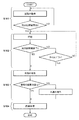
図4は、放射線撮像装置Iの動作フローチャートを示している。工程S101では、放射線の照射開始を検知部40が検知するまでは、各センサSを行ごとに順に初期化することにより、センサアレイ10のリセット処理を繰り返し行う。これは、各画素Pの薄膜トランジスタTを導通状態にすることによって為され、この動作を「空読み動作」という。この空読み動作は、各センサSにおいて生じる暗電流によって蓄積された電荷を初期化するものである。空読み動作を行っている間は、例えば、信号読出部30を休止状態にすることにより、消費電力を低減することができる。工程S102に進むまでは空読み動作が繰り返し為され、各センサSは周期的に初期化される。放射線の照射開始を検知部40が検知したことに応答して、工程S102では、放射線撮像装置Iは、例えば、放射線の照射終了を検知部40が検知するまで待機する。この工程では、各画素Pの薄膜トランジスタTは非導通状態であり、各センサSにおいて発生した電荷は蓄積される。蓄積される電荷の量は照射された放射線量に基づく。その後、放射線の照射の終了を検知部40が検知したことに応答して、工程S103では、センサアレイ10の信号の読み出しを行ごとに順に行う。これは、空読み動作と同様に、各画素Pの薄膜トランジスタTを導通状態にすることによって為され、この動作を「本読み動作」という。空読み動作を行っている間に信号読出部30を休止状態にしている場合は、本読み動作に移行する際に信号読出部30を動作可能な状態にする。当該本読み動作により得られた信号は、前述のように処理部60に出力される。ここで、当該信号は処理部60によって解析され、例えば、当該本読み動作が放射線の照射中に開始されたものであるか否かの判断が為されうる。この結果、当該本読み動作が放射線の照射中に開始されたものである場合、本読み動作が再び為される。その後、工程S104では、以上の動作で得られた信号に基づいて、処理部60により画像データが生成される。
FIG. 4 shows an operation flowchart of the radiation imaging apparatus I. In step S101, until the
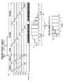
図5は、放射線の照射中に1回目の本読み動作が開始された場合の放射線撮像装置Iのタイミングチャートを示している。横軸は、時間軸として示し、上から順に、放射線の強度波形X(t)、制御信号線Vg(Vg1〜Vg6)を伝搬するパルス波形、アナログデジタル変換部ADC1の出力ADC_OUT、および対応するデジタル信号Dを示している。ここでは、説明を簡易化するため、放射線は、全てのセンサSに均一に入射した場合を考え、第3行目までの読み出しが為された時点で、放射線の照射を終了している場合を考える。この場合、第1〜3行目のセンサSについては、放射線の照射が為されている間に本読み動作が為されているため、当該本読み動作が為された後に蓄積された電荷に相当する信号は読み出されない。よって、読み出されなかった信号が最も大きい第1行目のセンサSの信号D1が最も小さい値になっており、第2行目、第3行目の順に信号D1が大きい値になっている。一方、第4〜6行目のセンサSについては、放射線の照射が終了した後に本読み動作が為されているため、放射線の照射中に蓄積された電荷に相当する信号の全てが読み出されている。よって、第4〜6行目のセンサSの信号D1が最も高い値であり、互いに同じ値になっている。 FIG. 5 shows a timing chart of the radiation imaging apparatus I when the first actual reading operation is started during radiation irradiation. The horizontal axis is shown as a time axis, and in order from the top, the radiation intensity waveform X (t), the pulse waveform propagating through the control signal lines Vg (Vg1 to Vg6), the output ADC_OUT of the analog-to-digital converter ADC1, and the corresponding digital Signal D is shown. Here, in order to simplify the explanation, the case where the radiation is uniformly incident on all the sensors S is considered, and the case where the radiation irradiation is finished at the time when the reading up to the third row is performed. Think. In this case, for the sensors S in the first to third rows, since the main reading operation is performed while radiation is being performed, a signal corresponding to the charge accumulated after the main reading operation is performed. Is not read. Thus, signal D 1 of the signal that was not read out the largest first line of the sensor S and becomes the smallest value, is the second row, signal D 1 is greater value in the order of the third row ing. On the other hand, for the sensors S in the fourth to sixth rows, since the main reading operation is performed after the radiation irradiation is completed, all the signals corresponding to the charges accumulated during the radiation irradiation are read out. Yes. Thus, signal D 1 of the fourth to sixth row of the sensor S is the highest value, which is the same value each other.
その後、2回目の本読み動作が開始される。ここでは、第1〜3行目のセンサSについては、1回目の本読み動作の後から放射線の照射が終了するまでの間に蓄積された電荷に相当する信号が読み出されるため、第1行目、第2行目、第3行目の順に信号D2が小さい値になる。一方、第4〜6行目のセンサSについては、放射線の照射に基づく信号は1回目の本読み動作で全て読み出されているため、2回目の本読み動作によっては信号D2を得られない。 Thereafter, the second main reading operation is started. Here, for the sensors S in the first to third rows, a signal corresponding to the electric charge accumulated between the first read operation and the end of radiation irradiation is read out. , second row, signal D 2 is smaller in the order of the third row. On the other hand, the sensor S of the 4-6 line, the signal based on the irradiation of radiation are all read out by the first real reading operation can not be obtained a signal D 2 is the second real reading operation.
このように、制御部50は、放射線の照射後に1回目の本読み動作(第1読出)と、その後に2回目の本読み動作(第2読出)と、を行うように駆動部20を制御する。即ち、第1読出は、検知部40の検知結果に応答して為され、センサアレイ10において蓄積された電荷に応じた信号(信号D1)をセンサアレイ10から読み出す。第2読出は、少なくとも、第1読出が放射線の照射が為されている間に開始されたものである場合に為され、センサアレイ10から更に信号(信号D2)を読み出す。第1読出が放射線の照射が為されている間に開始されたものであるか否かは、例えば、第1読出で得られた信号が所定の基準値に達しているか否かで判断してもよい。ここで、第2読出が為される場合として、例えば、放射線の照射が終了していないにもかかわらず、検知部40が放射線の照射が終了したと誤って検知してしまう場合が考えられる。このことは、例えば、外部環境によって突発的にノイズが生じた場合や、放射線源の出力が弱まってしまった場合など、意図しない原因に起因して起こりうる。また、例えば、放射線の照射が開始されたことを検知部40が検知した後、予め設定されたタイムアウト時間が経過したために強制的に第1読出を開始する場合、具体的には、検知部40が放射線の照射終了を検知できなかった場合が考えられる。これらの場合においては、放射線の照射が為されている間に第1読出が為されているため、信号D1は、第1読出が為された後に蓄積された電荷に相当する信号(即ち、信号D2)を含まない。そこで、この信号D2を取得するため、前述の第2読出を行う。
In this way, the
ここで、処理部60は、例えば、図5に示されるように、第1読出によって得られた信号D1と、第2読出によって得られた信号D2とを加算することによって信号D1を補正し、信号DHを得る。このようにして、第2読出によって得られた信号D2に基づいて、第1読出によって得られた信号D1を補正することにより信号DHを取得し、適切な放射線画像を生成することが可能となる。
Here, for example, as illustrated in FIG. 5, the
以上の動作によると、第1読出が為された後に照射されている放射線が含む情報を第2読出によって取得し、該第2読出で得られた情報を用いて、第1読出で得られた情報を補うことができる。よって、本実施形態によると、放射線画像を高品質化することができる。 According to the above operation, the information included in the radiation irradiated after the first reading is obtained is obtained by the second reading, and the information obtained by the second reading is obtained by the first reading. Information can be supplemented. Therefore, according to this embodiment, the quality of the radiation image can be improved.
本実施形態では、第1読出、第2読出、及び処理部60による補正のそれぞれを、センサアレイ10の1行単位で行う場合を例示したが、2行単位(又は3行以上の単位)で行ってもよい。また、少なくとも、第1読出が放射線の照射が為されている間に開始されたものである場合に、第2読出を行うように設計すればよく、第1読出の結果にかかわらず第2読出を行って前述の補正を行ってもよい。また、図6に例示されるように、第2読出が放射線の照射が為されている間に開始されたものである場合には、更にセンサアレイ10から信号(信号D3)を読み出す第3読出を行ってもよい。更には、放射線撮像装置Iの仕様の範囲内である限り、4回以上の本読み動作を行い同様の補正を行ってもよい。また、例えば、図7に示されるように、第2読出は、第1読出よりも短い期間で為されてもよい。この方法によると、例えば、放射線の強度波形の波尾長が短い場合には、前述の各実施形態よりも短い時間で同様の効果を得つつ放射線画像を取得することが可能であり、また、消費電力を低減することもできる。その他、本実施形態のセンサアレイ10では、照射された放射線をシンチレータによって光に変換してから光電変換によって電気信号に変換する構成を例示したが、本願発明は該構成に限られない。例えば、アモルファスセレニウムで構成された光電変換素子をセンサSに用いて、直接、放射線を電気信号に変換する構成を採ってもよい。
In the present embodiment, the case where each of the first reading, the second reading, and the correction by the
(第2実施形態)
図8を参照しながら、第2実施形態の放射線撮像装置Iを説明する。本実施形態では、制御部50は、図8(a)に例示されるように、第2読出を行った後に、更にオフセット読出を行う点で第1実施形態と異なる。オフセット読出では、第2読出を行った後に、センサアレイ10から更に信号を読み出し、センサアレイ10の信号のオフセット成分を取得する。このオフセット成分は、信号読出部30が有するオフセット成分、又はセンサアレイ10で生じる暗電流がもたらすノイズ成分を含む。処理部60は、第1実施形態で述べた補正において、当該オフセット成分を除去する処理を行うとよい。具体的には、各々がオフセット成分に対応する信号DNを含む信号D1と信号D2とを加算した信号DHから、2×DN相当の信号を減算する処理すればよい。このようにして、放射線画像をさらに高画質化することができる。図8(b)に示されるように、第2読出とオフセット読出と間に空読み動作が為されてもよい。
(Second Embodiment)
A radiation imaging apparatus I according to the second embodiment will be described with reference to FIG. In this embodiment, as illustrated in FIG. 8A, the
(第3実施形態)
図9乃至12を参照しながら、第3実施形態の放射線撮像装置Iを説明する。本実施形態で述べるように、本読み動作が放射線の照射が為されている間に開始されたものであるか否かは、例えば、読み出した信号の各々についての標準偏差σから判断してもよい。本読み動作により得られる信号Dの標準偏差σが大きいことは、例えば、信号Dが被検者の体内の情報を有していると判断できる。例えば、処理部60は、本読み動作を1行単位で行い、これによって得られた当該行の列ごとの信号から標準偏差σを算出する処理を、当該本読み動作と並列して行う。算出された標準偏差σに基づいて、例えば、所定の基準値σTに達しているか否かによって、その本読み動作が放射線の照射が為されている間に開始されたものであるか否かの判断が為されうる。
(Third embodiment)
A radiation imaging apparatus I according to the third embodiment will be described with reference to FIGS. As described in the present embodiment, whether or not the main reading operation is started while radiation is being performed may be determined from, for example, the standard deviation σ for each of the read signals. . If the standard deviation σ of the signal D obtained by the main reading operation is large, for example, it can be determined that the signal D has information in the body of the subject. For example, the
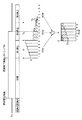
例えば、図9は、2000行×2000列のセンサアレイ10を有する放射線撮像装置Iにおいて、放射線の照射中に本読み動作が開始され、1000行分のセンサSの信号が当該照射中に読み出された場合を例示している。本実施形態では、第2読出により得られた信号D2の標準偏差σは、第1000行目を境に小さくなっている。このことから、第1読出によって得られた信号D1と、第2読出によって得られた信号D2とから信号DHを取得し、また、第3読出を行わないことを決定し、その後、前述と同様にして放射線画像を生成することが可能となる。本実施形態によると、本読み動作は、センサアレイ10の最後の行まで行うこともできるが(図10(a)参照)、途中で中断することもでき、これによると、例えば、消費電力を低減することができる((図10(b))参照)。
For example, in FIG. 9, in the radiation imaging apparatus I having the
また、本実施形態によると、放射線の照射中に本読み動作が為されたセンサアレイ10がいずれの行までであるかを特定することができる。図11は、放射線の照射が開始されたことを検知部40が検知した後、予め設定されたタイムアウト時間が経過したために強制的に第1読出が開始された場合を示している。本実施形態によると、タイムアウト時間が不適切であったと判断できる場合には、タイムアウト時間を適切な時間に更新することも可能である(図12参照)。
Further, according to the present embodiment, it is possible to specify up to which row the
以上の3つの実施形態を述べたが、本発明はこれらに限られるものではなく、目的、状態、用途及び機能その他の仕様に応じて、適宜、変更が可能であり、他の実施形態によっても為されうる。 Although the above-described three embodiments have been described, the present invention is not limited to these embodiments, and can be appropriately changed according to the purpose, state, application, function, and other specifications. Can be done.
(放射線撮像システム)
上述の各実施形態の放射線撮像装置Iは、図13に例示されるように、放射線撮像システム100に適用されうる。放射線は、X線、α線、β線、γ線等の電磁波や粒子線を含む。例えば、曝射スイッチ110を押すことにより、放射線制御部111において設定された条件にしたがって、放射線が放射線源112から照射される。これに応答して、放射線撮像装置Iにより前述の各実施形態で述べた動作が為される。
(Radiation imaging system)
The radiation imaging apparatus I of each embodiment described above can be applied to the
また、放射線撮像装置Iは、前述の各ユニットの他、当該各ユニットに電源を供給するバッテリ120と、外部のシステムSYSと通信する無線通信機701と、当該装置の位置情報を検出するためのセンサSとを含みうる。また、システムSYSは、例えば、当該通信のための無線通信機702、コンピュータ130およびディスプレイ140を有する。コンピュータ130は、当該通信により放射線撮像装置Iを管理し、その動作を制御する機能や、例えば、病院の内部のネットワークを介して必要な情報を送受信する機能を有しうる。また、コンピュータ130は、ディスプレイ140に表示されるGUI(Graphical User Interface)を制御ないし表示する機能や、放射線撮像装置Iからの画像信号を処理する機能を有しうる。これらの機能は、ソフトウェア上において実現されてもよいし、専用ICやプログラム可能なICによってハードウェアを用いて実現されてもよい。
The radiation imaging apparatus I includes other units mentioned above, the
その他、放射線撮像の際には、散乱線を除去するためのグリッドを用いても良い。放射線撮像装置Iは、ブッキーテーブルや臥位タイプのスタンドを用いて使用してもよい。放射線撮像装置Iは、バッテリ120用の充電器をさらに含んでもよい。コンピュータ130については、複数のコンピュータ130を使用してもよいし、モバイル用のパソコンを用いてもよい。無線通信を行うための電波が十分に得られない場合は、ケーブル等の有線通信によって通信してもよい。また、放射線撮像装置Iは複数のシステムSYSと通信してもよい。
In addition, a grid for removing scattered radiation may be used in radiation imaging. The radiation imaging apparatus I may be used using a bucky table or a recumbent type stand. The radiation imaging apparatus I may further include a charger for the
Claims (9)
前記照射された放射線を検知するための検知部と、
放射線の照射開始前において前記センサアレイを繰り返しリセットし、前記検知部による放射線の照射開始の検知に応じて前記センサアレイを待機状態にし、その後、前記センサアレイを駆動して前記センサアレイから前記待機状態の間に照射された放射線量に応じた信号を出力させる駆動部と、
前記駆動部を制御する制御部と、を備える放射線撮像装置であって、
前記制御部は、
前記待機状態の間に照射された放射線量に応じた信号を前記センサアレイから出力させる第1読出を行い、
放射線の照射中に前記第1読出が開始された場合には、前記第1読出の後に、前記第1読出の開始の後に照射された放射線量に応じた信号を前記センサアレイから更に出力させる第2読出を行い、
放射線の照射終了後に前記第1読出が開始された場合には前記第2読出を行わない、
ように前記駆動部を制御する
ことを特徴とする放射線撮像装置。 A sensor array that outputs a signal in accordance with the irradiated radiation;
A detector for detecting the irradiated radiation;
The sensor array is repeatedly reset before the start of radiation irradiation, and the sensor array is set in a standby state in response to detection of the start of radiation irradiation by the detection unit, and then the sensor array is driven to start the standby from the sensor array. A drive unit that outputs a signal according to the radiation dose irradiated during the state ;
A radiation imaging apparatus and a control unit for controlling the pre-SL driver,
The controller is
Performing a first readout for outputting a signal corresponding to the radiation dose irradiated during the standby state from the sensor array;
When the first reading is started during radiation irradiation, a signal corresponding to the radiation dose irradiated after the first reading is started is further output from the sensor array after the first reading. 2 read out,
When the first reading is started after the end of radiation irradiation, the second reading is not performed.
The drive unit is controlled as described above .
ことを特徴とする請求項1に記載の放射線撮像装置。 The first reading is started in response to the detection unit detecting that the irradiation of radiation has ended.
The radiation imaging apparatus according to claim 1.
前記予め設定された時間はタイムアウト時間であり、前記制御部は前記第2読出の結果に基づいて該タイムアウト時間を更新する、
ことを特徴とする請求項1に記載の放射線撮像装置。 The first reading is started in response to the elapse of a preset time after detecting the start of radiation irradiation ,
The preset time is time-out period, the control unit to update the time-out time based on the result of the second reading,
The radiation imaging apparatus according to claim 1.
前記処理部は、前記第1読出によって得られた信号と、前記第2読出によって得られた信号とを加算することにより、前記第1読出によって得られた信号を補正する、
ことを特徴とする請求項1乃至3のいずれか1項に記載の放射線撮像装置。 A processing unit for correcting the signal obtained by the first reading based on the signal obtained by the second reading;
The processing unit corrects the signal obtained by the first reading by adding the signal obtained by the first reading and the signal obtained by the second reading.
The radiation imaging apparatus according to claim 1, wherein:
前記処理部は、前記加算して得られた信号から前記オフセット成分を除去する、
ことを特徴とする請求項4に記載の放射線撮像装置。 The controller obtains an offset component of the signal of the sensor array by further reading a signal from the sensor array after performing the second reading,
The processing unit removes the offset component from the signal obtained by the addition,
The radiation imaging apparatus according to claim 4 .
ことを特徴とする請求項4又は請求項5に記載の放射線撮像装置。 The sensor array includes a plurality of sensors arranged to form a plurality of rows and a plurality of columns, and the first reading, the second reading, and the correction by the processing unit are the rows of the plurality of sensors. Done every time,
6. The radiation imaging apparatus according to claim 4 or 5 , wherein:
ことを特徴とする請求項6に記載の放射線撮像装置。 The control unit is configured to perform radiation irradiation in the first reading based on a standard deviation calculated for a signal for each column of the plurality of sensors obtained by the first reading performed for each row of the plurality of sensors. To determine if it was started while
The radiation imaging apparatus according to claim 6.
放射線を発生させるための放射線源と、
を具備することを特徴とする放射線撮像システム。 The radiation imaging apparatus according to any one of claims 1 to 7,
A radiation source for generating radiation;
A radiation imaging system comprising:
放射線の照射開始前において前記センサアレイを繰り返しリセットし、前記検知部による放射線の照射開始の検知に応じて前記センサアレイを待機状態にする第1工程と、
前記第1工程の後、前記センサアレイを駆動して前記センサアレイから前記待機状態の間に照射された放射線量に応じた信号を読み出す第2工程と、
前記第2工程の信号の読み出しが放射線の照射中に開始された場合には、前記第2工程の後に、前記第2工程の信号の読み出しの開始の後に照射された放射線量に応じた信号を前記センサアレイから更に読み出し、前記第2工程の信号の読み出しが放射線の照射終了後に開始された場合には前記センサアレイから更に信号を読み出さない、ように前記センサアレイを制御する第3工程と、を有する、
ことを特徴とする放射線撮像装置の駆動方法。
A method of driving a radiation imaging apparatus, comprising: a sensor array that outputs a signal in accordance with irradiated radiation; and a detection unit for detecting the irradiated radiation,
A first step of repeatedly resetting the sensor array before the start of radiation irradiation and placing the sensor array in a standby state in response to detection of the start of radiation irradiation by the detection unit;
After the first step, a second step of driving the sensor array and reading a signal corresponding to the radiation dose irradiated from the sensor array during the standby state;
When reading of the signal in the second step is started during radiation irradiation, a signal corresponding to the amount of radiation irradiated after the start of reading of the signal in the second step is given after the second step. A third step of controlling the sensor array so that no further signal is read from the sensor array when further reading from the sensor array and reading of the signal of the second step is started after the end of radiation irradiation ; Having
A method for driving a radiation imaging apparatus.
Priority Applications (2)
| Application Number | Priority Date | Filing Date | Title |
|---|---|---|---|
| JP2012192290A JP6087541B2 (en) | 2012-08-31 | 2012-08-31 | Radiation imaging apparatus, driving method thereof, and radiation imaging system |
| US14/010,449 US9035265B2 (en) | 2012-08-31 | 2013-08-26 | Radiation imaging apparatus, method for driving the same and radiation imaging system |
Applications Claiming Priority (1)
| Application Number | Priority Date | Filing Date | Title |
|---|---|---|---|
| JP2012192290A JP6087541B2 (en) | 2012-08-31 | 2012-08-31 | Radiation imaging apparatus, driving method thereof, and radiation imaging system |
Publications (2)
| Publication Number | Publication Date |
|---|---|
| JP2014049979A JP2014049979A (en) | 2014-03-17 |
| JP6087541B2 true JP6087541B2 (en) | 2017-03-01 |
Family
ID=50186131
Family Applications (1)
| Application Number | Title | Priority Date | Filing Date |
|---|---|---|---|
| JP2012192290A Active JP6087541B2 (en) | 2012-08-31 | 2012-08-31 | Radiation imaging apparatus, driving method thereof, and radiation imaging system |
Country Status (2)
| Country | Link |
|---|---|
| US (1) | US9035265B2 (en) |
| JP (1) | JP6087541B2 (en) |
Families Citing this family (7)
| Publication number | Priority date | Publication date | Assignee | Title |
|---|---|---|---|---|
| EP3230769B1 (en) * | 2014-12-11 | 2019-01-23 | Carestream Health, Inc. | Beam detection with continuous detector readout |
| JP6525756B2 (en) | 2015-06-15 | 2019-06-05 | キヤノン株式会社 | Radiation imaging apparatus and control method thereof |
| JP6366542B2 (en) | 2015-06-17 | 2018-08-01 | キヤノン株式会社 | Radiation imaging apparatus, radiation imaging system, and irradiation start detection method |
| JP6668717B2 (en) * | 2015-12-04 | 2020-03-18 | コニカミノルタ株式会社 | Radiation imaging apparatus and radiation imaging system |
| CN110022771B (en) | 2016-11-23 | 2023-04-18 | 卡尔斯特里姆保健公司 | Synchronization for dynamic imaging |
| JP7075250B2 (en) | 2018-03-20 | 2022-05-25 | キヤノン株式会社 | Radiation imaging system, imaging control device and method |
| WO2023084829A1 (en) * | 2021-11-10 | 2023-05-19 | 株式会社村田製作所 | Excitation circuit, vibration device, and vehicle |
Family Cites Families (23)
| Publication number | Priority date | Publication date | Assignee | Title |
|---|---|---|---|---|
| JP3556029B2 (en) | 1995-11-27 | 2004-08-18 | 東芝医用システムエンジニアリング株式会社 | X-ray imaging device |
| US5818898A (en) * | 1995-11-07 | 1998-10-06 | Kabushiki Kaisha Toshiba | X-ray imaging apparatus using X-ray planar detector |
| US5969360A (en) * | 1997-11-26 | 1999-10-19 | Direct Radiography Corp. | Readout sequence for residual image elimination in a radiation detection panel |
| US6510202B2 (en) * | 2000-03-31 | 2003-01-21 | Canon Kabushiki Kaisha | Imaging apparatus, imaging method, and storage medium |
| JP3890210B2 (en) * | 2000-08-11 | 2007-03-07 | キヤノン株式会社 | Image capturing apparatus and method for controlling image capturing apparatus |
| JP4746741B2 (en) | 2000-12-14 | 2011-08-10 | キヤノン株式会社 | Radiation imaging apparatus and system |
| JP4468083B2 (en) * | 2003-08-26 | 2010-05-26 | キヤノン株式会社 | Radiographic apparatus and radiographic method |
| JP2007151761A (en) * | 2005-12-02 | 2007-06-21 | Canon Inc | Apparatus, system, method, and program for radiation imaging |
| JP5159161B2 (en) * | 2006-06-26 | 2013-03-06 | キヤノン株式会社 | Radiation imaging apparatus, radiation imaging system and control method thereof |
| JP4991459B2 (en) * | 2007-09-07 | 2012-08-01 | キヤノン株式会社 | Imaging apparatus and radiation imaging system |
| JP5199735B2 (en) * | 2008-06-06 | 2013-05-15 | 富士フイルム株式会社 | Radiation image data correction method and apparatus, and radiation image photographing apparatus |
| JP5792923B2 (en) * | 2009-04-20 | 2015-10-14 | キヤノン株式会社 | Radiation imaging apparatus, radiation imaging system, control method thereof, and program thereof |
| JP5233831B2 (en) | 2009-05-14 | 2013-07-10 | コニカミノルタエムジー株式会社 | Radiographic imaging apparatus and radiographic imaging system |
| WO2010150381A1 (en) * | 2009-06-25 | 2010-12-29 | キヤノン株式会社 | Radiation imaging device and radiation imaging system, and method and program for controlling same |
| JP4854769B2 (en) * | 2009-06-30 | 2012-01-18 | キヤノン株式会社 | Imaging apparatus, imaging system, and control method thereof |
| JP2011172606A (en) * | 2010-02-23 | 2011-09-08 | Konica Minolta Medical & Graphic Inc | Radiographic apparatus and radiographic system |
| JP2011177356A (en) * | 2010-03-02 | 2011-09-15 | Konica Minolta Medical & Graphic Inc | Radiographic apparatus |
| JP2011185800A (en) * | 2010-03-10 | 2011-09-22 | Konica Minolta Medical & Graphic Inc | Radiographic image photographing apparatus and radiographic image photographing system |
| JP2012045044A (en) * | 2010-08-24 | 2012-03-08 | Fujifilm Corp | Radiation image detection device |
| JP5289477B2 (en) * | 2011-02-09 | 2013-09-11 | 富士フイルム株式会社 | Radiation image detection apparatus and radiation irradiation start detection method |
| JP5847413B2 (en) * | 2011-03-24 | 2016-01-20 | キヤノン株式会社 | Imaging apparatus, imaging system, and control method thereof |
| JP2012204966A (en) * | 2011-03-24 | 2012-10-22 | Canon Inc | Imaging apparatus, imaging system and control method therefor |
| JP5657491B2 (en) * | 2011-08-31 | 2015-01-21 | 富士フイルム株式会社 | Radiation image capturing apparatus, radiation image capturing system, radiation image capturing program, and radiation image capturing method |
-
2012
- 2012-08-31 JP JP2012192290A patent/JP6087541B2/en active Active
-
2013
- 2013-08-26 US US14/010,449 patent/US9035265B2/en active Active
Also Published As
| Publication number | Publication date |
|---|---|
| US9035265B2 (en) | 2015-05-19 |
| JP2014049979A (en) | 2014-03-17 |
| US20140061495A1 (en) | 2014-03-06 |
Similar Documents
| Publication | Publication Date | Title |
|---|---|---|
| JP6087541B2 (en) | Radiation imaging apparatus, driving method thereof, and radiation imaging system | |
| JP6585910B2 (en) | Radiation imaging apparatus and radiation imaging system | |
| JP6643871B2 (en) | Radiation imaging apparatus and photon counting method | |
| US9541653B2 (en) | Radiation imaging apparatus and radiation imaging system | |
| CN110623682B (en) | Radiation imaging apparatus, control method, radiation imaging system, and storage medium | |
| US9134432B2 (en) | Radiation imaging apparatus, method for controlling the same, and non-transitory computer-readable storage medium | |
| EP2716032B1 (en) | Imaging apparatus, control method therefor, and imaging system | |
| EP2651120B1 (en) | Radiation imaging apparatus, method of controlling the same, and radiation imaging system | |
| US8809795B2 (en) | Imaging apparatus, radiation imaging system, controlling method of imaging apparatus, and recording medium recording control program of imaging apparatus | |
| JP2014168205A (en) | Radiation imaging apparatus, radiation inspection apparatus, and signal correction method and program | |
| US8680471B2 (en) | Imaging apparatus, imaging system, method of controlling the apparatus and the system, and program | |
| US10234574B2 (en) | Radiation imaging apparatus, radiation imaging system, and irradiation start detection method | |
| JP5539139B2 (en) | IMAGING DEVICE, IMAGING SYSTEM, AND IMAGING DEVICE CONTROL METHOD | |
| JP4888599B2 (en) | Light or radiation imaging device | |
| US11294078B2 (en) | Radiation imaging apparatus and radiation imaging system | |
| US10274618B2 (en) | Radiography apparatus, radiography method, and radiography program | |
| KR20210020807A (en) | Methods and systems for increasing psrr compensation range in an image sensor | |
| JP6525756B2 (en) | Radiation imaging apparatus and control method thereof | |
| KR101689665B1 (en) | Image sensor, image sensing method, and image photographing apparatus including the image sensor | |
| JP6808458B2 (en) | Radiation imaging device and radiation imaging system | |
| JP2021035027A (en) | Radiation detecting apparatus, control method thereof, and radiation imaging system | |
| JP2019216875A (en) | Radiation imaging apparatus, radiation imaging system, control method of radiation imaging apparatus, and program | |
| US20230417934A1 (en) | Radiation imaging apparatus, radiation imaging system, control method for radiation imaging apparatus, non-transitory computer-readable storage medium, and signal processing apparatus | |
| WO2020149098A1 (en) | Radiographic imaging device and radiographic imaging system | |
| JP2017201750A (en) | Radiation imaging device, method for driving the same, and program |
Legal Events
| Date | Code | Title | Description |
|---|---|---|---|
| A621 | Written request for application examination |
Free format text: JAPANESE INTERMEDIATE CODE: A621 Effective date: 20150819 |
|
| A977 | Report on retrieval |
Free format text: JAPANESE INTERMEDIATE CODE: A971007 Effective date: 20160725 |
|
| A131 | Notification of reasons for refusal |
Free format text: JAPANESE INTERMEDIATE CODE: A131 Effective date: 20160805 |
|
| A521 | Request for written amendment filed |
Free format text: JAPANESE INTERMEDIATE CODE: A523 Effective date: 20160926 |
|
| TRDD | Decision of grant or rejection written | ||
| A01 | Written decision to grant a patent or to grant a registration (utility model) |
Free format text: JAPANESE INTERMEDIATE CODE: A01 Effective date: 20170106 |
|
| A61 | First payment of annual fees (during grant procedure) |
Free format text: JAPANESE INTERMEDIATE CODE: A61 Effective date: 20170202 |
|
| R151 | Written notification of patent or utility model registration |
Ref document number: 6087541 Country of ref document: JP Free format text: JAPANESE INTERMEDIATE CODE: R151 |