JP6365819B2 - Liquid ejector - Google Patents
Liquid ejector Download PDFInfo
- Publication number
- JP6365819B2 JP6365819B2 JP2014039406A JP2014039406A JP6365819B2 JP 6365819 B2 JP6365819 B2 JP 6365819B2 JP 2014039406 A JP2014039406 A JP 2014039406A JP 2014039406 A JP2014039406 A JP 2014039406A JP 6365819 B2 JP6365819 B2 JP 6365819B2
- Authority
- JP
- Japan
- Prior art keywords
- liquid ejecting
- head
- positioning
- liquid
- cap body
- Prior art date
- Legal status (The legal status is an assumption and is not a legal conclusion. Google has not performed a legal analysis and makes no representation as to the accuracy of the status listed.)
- Active
Links
- 239000007788 liquid Substances 0.000 title claims description 130
- 238000007789 sealing Methods 0.000 claims description 14
- 239000000945 filler Substances 0.000 claims description 7
- 239000000758 substrate Substances 0.000 description 62
- 238000004891 communication Methods 0.000 description 33
- 230000001681 protective effect Effects 0.000 description 15
- 239000000853 adhesive Substances 0.000 description 13
- 230000001070 adhesive effect Effects 0.000 description 13
- 239000010408 film Substances 0.000 description 12
- 239000000463 material Substances 0.000 description 10
- 238000012423 maintenance Methods 0.000 description 9
- XUIMIQQOPSSXEZ-UHFFFAOYSA-N Silicon Chemical compound [Si] XUIMIQQOPSSXEZ-UHFFFAOYSA-N 0.000 description 6
- 230000001965 increasing effect Effects 0.000 description 6
- 238000004519 manufacturing process Methods 0.000 description 6
- 229910052710 silicon Inorganic materials 0.000 description 6
- 239000010703 silicon Substances 0.000 description 6
- 229910001220 stainless steel Inorganic materials 0.000 description 6
- 239000010935 stainless steel Substances 0.000 description 6
- 238000005452 bending Methods 0.000 description 5
- 238000004140 cleaning Methods 0.000 description 5
- 229910052751 metal Inorganic materials 0.000 description 5
- 239000002184 metal Substances 0.000 description 5
- 239000013078 crystal Substances 0.000 description 4
- 238000010438 heat treatment Methods 0.000 description 4
- 238000005304 joining Methods 0.000 description 4
- 238000007639 printing Methods 0.000 description 4
- 239000012212 insulator Substances 0.000 description 3
- 238000003860 storage Methods 0.000 description 3
- 239000010409 thin film Substances 0.000 description 3
- 239000004734 Polyphenylene sulfide Substances 0.000 description 2
- 229910010293 ceramic material Inorganic materials 0.000 description 2
- 230000008859 change Effects 0.000 description 2
- 238000001816 cooling Methods 0.000 description 2
- 230000003028 elevating effect Effects 0.000 description 2
- 239000006112 glass ceramic composition Substances 0.000 description 2
- 230000000149 penetrating effect Effects 0.000 description 2
- 229920000069 polyphenylene sulfide Polymers 0.000 description 2
- 239000011347 resin Substances 0.000 description 2
- 229920005989 resin Polymers 0.000 description 2
- 238000007790 scraping Methods 0.000 description 2
- 229910018072 Al 2 O 3 Inorganic materials 0.000 description 1
- 238000000018 DNA microarray Methods 0.000 description 1
- VYPSYNLAJGMNEJ-UHFFFAOYSA-N Silicium dioxide Chemical compound O=[Si]=O VYPSYNLAJGMNEJ-UHFFFAOYSA-N 0.000 description 1
- QCWXUUIWCKQGHC-UHFFFAOYSA-N Zirconium Chemical compound [Zr] QCWXUUIWCKQGHC-UHFFFAOYSA-N 0.000 description 1
- 239000011358 absorbing material Substances 0.000 description 1
- 238000003491 array Methods 0.000 description 1
- 230000008901 benefit Effects 0.000 description 1
- 230000015572 biosynthetic process Effects 0.000 description 1
- 239000000919 ceramic Substances 0.000 description 1
- 238000005336 cracking Methods 0.000 description 1
- 230000002950 deficient Effects 0.000 description 1
- 238000006073 displacement reaction Methods 0.000 description 1
- 238000001035 drying Methods 0.000 description 1
- 239000000428 dust Substances 0.000 description 1
- 230000000694 effects Effects 0.000 description 1
- 230000005611 electricity Effects 0.000 description 1
- 239000007772 electrode material Substances 0.000 description 1
- 238000005530 etching Methods 0.000 description 1
- 238000002347 injection Methods 0.000 description 1
- 239000007924 injection Substances 0.000 description 1
- 239000004973 liquid crystal related substance Substances 0.000 description 1
- 238000001459 lithography Methods 0.000 description 1
- 230000005499 meniscus Effects 0.000 description 1
- 239000007769 metal material Substances 0.000 description 1
- 238000000034 method Methods 0.000 description 1
- 238000000465 moulding Methods 0.000 description 1
- 239000005416 organic matter Substances 0.000 description 1
- RVTZCBVAJQQJTK-UHFFFAOYSA-N oxygen(2-);zirconium(4+) Chemical compound [O-2].[O-2].[Zr+4] RVTZCBVAJQQJTK-UHFFFAOYSA-N 0.000 description 1
- 238000005192 partition Methods 0.000 description 1
- 230000002093 peripheral effect Effects 0.000 description 1
- 229920001721 polyimide Polymers 0.000 description 1
- 239000009719 polyimide resin Substances 0.000 description 1
- 239000011148 porous material Substances 0.000 description 1
- 230000009467 reduction Effects 0.000 description 1
- 238000004904 shortening Methods 0.000 description 1
- 229910052814 silicon oxide Inorganic materials 0.000 description 1
- 230000003068 static effect Effects 0.000 description 1
- 239000000126 substance Substances 0.000 description 1
- 230000009466 transformation Effects 0.000 description 1
- 229910052726 zirconium Inorganic materials 0.000 description 1
- 229910001928 zirconium oxide Inorganic materials 0.000 description 1
Images


Classifications
-
- B—PERFORMING OPERATIONS; TRANSPORTING
- B41—PRINTING; LINING MACHINES; TYPEWRITERS; STAMPS
- B41J—TYPEWRITERS; SELECTIVE PRINTING MECHANISMS, i.e. MECHANISMS PRINTING OTHERWISE THAN FROM A FORME; CORRECTION OF TYPOGRAPHICAL ERRORS
- B41J2/00—Typewriters or selective printing mechanisms characterised by the printing or marking process for which they are designed
- B41J2/005—Typewriters or selective printing mechanisms characterised by the printing or marking process for which they are designed characterised by bringing liquid or particles selectively into contact with a printing material
- B41J2/01—Ink jet
- B41J2/135—Nozzles
- B41J2/165—Prevention or detection of nozzle clogging, e.g. cleaning, capping or moistening for nozzles
- B41J2/16505—Caps, spittoons or covers for cleaning or preventing drying out
- B41J2/16508—Caps, spittoons or covers for cleaning or preventing drying out connected with the printer frame
-
- B—PERFORMING OPERATIONS; TRANSPORTING
- B41—PRINTING; LINING MACHINES; TYPEWRITERS; STAMPS
- B41J—TYPEWRITERS; SELECTIVE PRINTING MECHANISMS, i.e. MECHANISMS PRINTING OTHERWISE THAN FROM A FORME; CORRECTION OF TYPOGRAPHICAL ERRORS
- B41J2/00—Typewriters or selective printing mechanisms characterised by the printing or marking process for which they are designed
- B41J2/005—Typewriters or selective printing mechanisms characterised by the printing or marking process for which they are designed characterised by bringing liquid or particles selectively into contact with a printing material
- B41J2/01—Ink jet
- B41J2/135—Nozzles
- B41J2/14—Structure thereof only for on-demand ink jet heads
- B41J2/14201—Structure of print heads with piezoelectric elements
- B41J2/14233—Structure of print heads with piezoelectric elements of film type, deformed by bending and disposed on a diaphragm
-
- B—PERFORMING OPERATIONS; TRANSPORTING
- B41—PRINTING; LINING MACHINES; TYPEWRITERS; STAMPS
- B41J—TYPEWRITERS; SELECTIVE PRINTING MECHANISMS, i.e. MECHANISMS PRINTING OTHERWISE THAN FROM A FORME; CORRECTION OF TYPOGRAPHICAL ERRORS
- B41J2/00—Typewriters or selective printing mechanisms characterised by the printing or marking process for which they are designed
- B41J2/005—Typewriters or selective printing mechanisms characterised by the printing or marking process for which they are designed characterised by bringing liquid or particles selectively into contact with a printing material
- B41J2/01—Ink jet
- B41J2/135—Nozzles
- B41J2/165—Prevention or detection of nozzle clogging, e.g. cleaning, capping or moistening for nozzles
- B41J2/16505—Caps, spittoons or covers for cleaning or preventing drying out
- B41J2/16508—Caps, spittoons or covers for cleaning or preventing drying out connected with the printer frame
- B41J2/16511—Constructions for cap positioning
-
- B—PERFORMING OPERATIONS; TRANSPORTING
- B41—PRINTING; LINING MACHINES; TYPEWRITERS; STAMPS
- B41J—TYPEWRITERS; SELECTIVE PRINTING MECHANISMS, i.e. MECHANISMS PRINTING OTHERWISE THAN FROM A FORME; CORRECTION OF TYPOGRAPHICAL ERRORS
- B41J2/00—Typewriters or selective printing mechanisms characterised by the printing or marking process for which they are designed
- B41J2/005—Typewriters or selective printing mechanisms characterised by the printing or marking process for which they are designed characterised by bringing liquid or particles selectively into contact with a printing material
- B41J2/01—Ink jet
- B41J2/135—Nozzles
- B41J2/14—Structure thereof only for on-demand ink jet heads
- B41J2002/14362—Assembling elements of heads
-
- B—PERFORMING OPERATIONS; TRANSPORTING
- B41—PRINTING; LINING MACHINES; TYPEWRITERS; STAMPS
- B41J—TYPEWRITERS; SELECTIVE PRINTING MECHANISMS, i.e. MECHANISMS PRINTING OTHERWISE THAN FROM A FORME; CORRECTION OF TYPOGRAPHICAL ERRORS
- B41J2/00—Typewriters or selective printing mechanisms characterised by the printing or marking process for which they are designed
- B41J2/005—Typewriters or selective printing mechanisms characterised by the printing or marking process for which they are designed characterised by bringing liquid or particles selectively into contact with a printing material
- B41J2/01—Ink jet
- B41J2/135—Nozzles
- B41J2/14—Structure thereof only for on-demand ink jet heads
- B41J2002/14419—Manifold
-
- B—PERFORMING OPERATIONS; TRANSPORTING
- B41—PRINTING; LINING MACHINES; TYPEWRITERS; STAMPS
- B41J—TYPEWRITERS; SELECTIVE PRINTING MECHANISMS, i.e. MECHANISMS PRINTING OTHERWISE THAN FROM A FORME; CORRECTION OF TYPOGRAPHICAL ERRORS
- B41J2/00—Typewriters or selective printing mechanisms characterised by the printing or marking process for which they are designed
- B41J2/005—Typewriters or selective printing mechanisms characterised by the printing or marking process for which they are designed characterised by bringing liquid or particles selectively into contact with a printing material
- B41J2/01—Ink jet
- B41J2/135—Nozzles
- B41J2/14—Structure thereof only for on-demand ink jet heads
- B41J2002/14491—Electrical connection
Landscapes
- Particle Formation And Scattering Control In Inkjet Printers (AREA)
- Ink Jet (AREA)
Description
本発明は、液体を噴射する液体噴射ヘッド及び液体噴射ヘッドをキャップするキャップ本体を有する液体噴射装置に関する。 The present invention relates to a liquid ejecting head that ejects liquid and a liquid ejecting apparatus that includes a cap body that caps the liquid ejecting head.
液体噴射装置としては、例えば、液体としてインクをインク滴として吐出するインクジェット式記録ヘッドを具備し、インクジェット式記録ヘッドのノズルから吐出されたインク滴を記録用紙等の被噴射媒体に着弾させてドットを形成することで画像等の記録を行うインクジェット式記録装置が挙げられる。 The liquid ejecting apparatus includes, for example, an ink jet recording head that ejects ink as ink droplets as a liquid, and ink droplets ejected from nozzles of the ink jet recording head are landed on an ejected medium such as recording paper. An ink jet recording apparatus that records an image or the like by forming an image can be used.
このようなインクジェット式記録装置では、増粘したインク、気泡や塵埃などの異物が混入したインクをノズル開口から吸引するためのキャップ本体が設けられている(特許文献1参照)。 Such an ink jet recording apparatus is provided with a cap main body for sucking thickened ink and ink mixed with foreign matters such as bubbles and dust from a nozzle opening (see Patent Document 1).
キャップ本体は、インクジェット式記録ヘッドを支持する支持フレームに凸部を設け、キャップ本体に凹部を設け、凸部と凹部とを嵌合させることで、両者の位置決めが行われている。 The cap main body is provided with a convex portion on a support frame that supports the ink jet recording head, a concave portion is provided on the cap main body , and the convex portion and the concave portion are fitted with each other, thereby positioning the both.
しかしながら、キャップ本体に設けられたシール部材は、インクジェット式記録ヘッドの液体噴射面に当接して密封するため、キャップ本体を支持フレーム等に位置決めする場合、インクジェット式記録ヘッドを構成する部材や支持フレーム等の部材の寸法公差や互いの位置ずれによる誤差が積算されて、シール部材の封止領域への位置決めに大きな誤差が生じてしまう虞があるという問題がある。 However, since the seal member provided in the cap main body contacts and seals the liquid ejection surface of the ink jet recording head, when the cap main body is positioned on the support frame or the like, the member constituting the ink jet recording head or the support frame There is a problem in that errors due to dimensional tolerances of the members and the like and errors due to mutual positional deviation may be integrated, resulting in a large error in positioning the sealing member in the sealing region.
また、シール部材が位置ずれしてもノズル開口を確実にシールするためには、シール部材が当接する余白部分を大きくしなくてはならず、インクジェット式記録ヘッドが大型化してしまうという問題がある。 Further, in order to reliably seal the nozzle opening even if the seal member is displaced, there is a problem that the margin part where the seal member abuts must be increased, and the ink jet recording head is increased in size. .
なお、このような問題はインクジェット式記録装置だけではなく、インク以外の液体を噴射する液体噴射装置においても同様に存在する。 Such a problem exists not only in the ink jet recording apparatus but also in a liquid ejecting apparatus that ejects liquid other than ink.
本発明はこのような事情に鑑み、キャップ本体の液体噴射ヘッドへの位置決め精度を向上して、小型化を図ることができる液体噴射装置を提供することを目的とする。 SUMMARY An advantage of some aspects of the invention is that it provides a liquid ejecting apparatus that can improve the positioning accuracy of a cap body to a liquid ejecting head and can be downsized.
上記課題を解決する本発明の態様は、液体を噴射するノズル開口が形成された液体噴射面を有するヘッド本体と、流路部材と、複数の前記ノズル開口が形成された領域の外側に配置された位置決め当接部であるカバーと、を有する液体噴射ヘッドと、前記液体噴射ヘッドと相対的に移動可能に配置され、前記液体噴射面と交差した方向に起立する側壁を有するキャップ本体と、前記キャップ本体の内側に収容配置され、前記液体噴射ヘッドと前記キャップ本体との相対的な移動によって前記領域を取り囲んだ状態で前記位置決め当接部と前記側壁とが当接して、前記キャップ本体の内側に密封空間を形成するシール部材と、を備え、前記キャップ本体の前記側壁が、前記液体噴射面の面方向に沿った方向のうちの一方で前記位置決め当接部と当接することで、前記液体噴射ヘッドと前記シール部材との前記液体噴射面に沿った方向の相対位置が規定され、前記カバーは、前記液体噴射面の面方向に沿った方向のうちの一方に対応する端部において、屈曲部を有し、前記屈曲部と前記流路部材との間には、充填剤が充填されており、前記側壁は、前記位置決め当接部に当接する位置決め面を有し、前記屈曲部は、前記側壁の前記位置決め面に対して傾斜して設けられていることを特徴とする液体噴射装置にある。
かかる態様では、シール部材が当接する位置決め当接部にキャップ本体の側壁を当接させて位置決めするため、シール部材と位置決め当接部との間にはキャップ本体が介在されるだけとなるので、介在する複数の部品の寸法公差や互いの位置ずれなどの誤差が積算されて大きな誤差が生じるのを抑制して、シール部材を位置決め当接部に対して高精度に位置決めすることが可能となる。したがって、シール部材が当接する領域に位置ずれを考慮した余分な領域を形成する必要がなく、液体噴射ヘッドを小型化することができると共にキャップ本体を小型化することができる。
また、屈曲部によってカバーの剛性が向上すると共に、屈曲部と流路部材との間に充填剤を充填することで、屈曲部の剛性を向上して、側壁が屈曲部に当接した際に屈曲部の変形を抑制することができる。
さらに、屈曲部を位置決め面に対して傾斜して設けることで、側壁の位置決め面と屈曲部とは面接触ではなく線接触するため、屈曲部に対するキャップ本体の位置決めを高精度に行うことができる。すなわち、位置決め面と屈曲部とを面接触させて位置決めさせる場合と比較して、屈曲部の高い面精度が必要となり製造工程を簡略化して、高い精度でキャップ本体のシール部材と液体噴射ヘッドとを位置決めすることができる。
また、前記位置決め当接部は、前記領域を取り囲むように配置されていることが好ましい。これによれば、屈曲部によって位置決め当接部の剛性が向上すると共に、キャップ本体の側壁が位置決め当接部に当接することによる変形を屈曲部によって抑制することができる。
また、前記位置決め当接部は、前記屈曲部を有すると共に、前記側壁の内側と面で当接する当接面を有することが好ましい。これによれば、側壁と屈曲部とが面接触するため、互いに削られる等の破壊が発生するのを抑制して、高精度な位置決めを維持することができる。
また、前記側壁は、前記位置決め当接部に対して、前記液体噴射ヘッドと被噴射媒体との相対移動方向の一方側で当接することが好ましい。これによれば、液体噴射ヘッドの相対移動方向の小型化を図ることができ、液体噴射ヘッドを挟んで設けられた搬送手段の搬送距離を短くして、被噴射媒体の姿勢を高精度に固定することができる。
また、前記位置決め当接部は、前記液体噴射面を露出可能な露出開口部を有し、該露出開口部と前記液体噴射面とは、当該液体噴射面の面内方向において隙間を介して配置されていることが好ましい。これによれば、液体噴射面を小型化してコストを低減することができる。
他の態様は、液体を噴射するノズル開口が形成された液体噴射面と、複数の前記ノズル開口が形成された領域の外側に配置された位置決め当接部と、を有する液体噴射ヘッドと、前記液体噴射ヘッドと相対的に移動可能に配置され、前記液体噴射面と交差した方向に起立する側壁を有するキャップ本体と、前記キャップ本体の内側に収容配置され、前記液体噴射ヘッドと前記キャップ本体との相対的な移動によって前記領域を取り囲んだ状態で前記位置決め当接部と前記側壁とが当接して、前記キャップ本体の内側に密封空間を形成するシール部材と、を備え、前記キャップ本体の前記側壁が、前記液体噴射面の面方向に沿った方向のうちの一方で前記位置決め当接部と当接することで、前記液体噴射ヘッドと前記シール部材との前記液体噴射面に沿った方向の相対位置が規定されることを特徴とする液体噴射装置にある。
An aspect of the present invention that solves the above problem is arranged outside a head body having a liquid ejection surface in which nozzle openings for ejecting liquid are formed , a flow path member, and a plurality of the nozzle openings. A liquid ejecting head having a cover that is a positioning contact portion, a cap main body having a side wall that is arranged to be movable relative to the liquid ejecting head and that stands in a direction intersecting the liquid ejecting surface; The positioning contact portion and the side wall are in contact with each other in a state of being housed and disposed inside the cap body and surrounding the region by relative movement of the liquid ejecting head and the cap body. And a sealing member that forms a sealed space, wherein the side wall of the cap body has one of the positioning contact portions in a direction along a surface direction of the liquid ejection surface, By contacting, the relative position of the liquid ejecting head and the seal member in the direction along the liquid ejecting surface is defined, and the cover corresponds to one of the directions along the surface direction of the liquid ejecting surface. A bent portion, and a filler is filled between the bent portion and the flow path member, and the side wall has a positioning surface that contacts the positioning contact portion. In the liquid ejecting apparatus, the bent portion is provided to be inclined with respect to the positioning surface of the side wall .
In this aspect, since the positioning is performed by bringing the side wall of the cap body into contact with the positioning contact portion with which the seal member contacts, the cap body is only interposed between the sealing member and the positioning contact portion. It is possible to position the seal member with high accuracy with respect to the positioning contact portion by suppressing the occurrence of a large error by integrating errors such as dimensional tolerances of a plurality of intervening parts and mutual positional deviations. . Therefore, it is not necessary to form an extra area in consideration of the positional deviation in the area where the seal member abuts, and the liquid ejecting head can be reduced in size and the cap body can be reduced in size.
In addition, the rigidity of the cover is improved by the bent portion, and the filler is filled between the bent portion and the flow path member, thereby improving the rigidity of the bent portion and when the side wall comes into contact with the bent portion. The deformation of the bent portion can be suppressed.
Furthermore, since the bent portion is inclined with respect to the positioning surface, the positioning surface of the side wall and the bent portion are not in surface contact but in line contact, so that the cap body can be positioned with high accuracy with respect to the bent portion. . That is, compared with the case where the positioning surface and the bent portion are brought into surface contact with each other, the surface accuracy of the bent portion is required and the manufacturing process is simplified. Can be positioned.
The positioning contact portion is preferably arranged so as to surround the region . According to this, the rigidity of the positioning contact portion is improved by the bent portion, and deformation due to the side wall of the cap body coming into contact with the positioning contact portion can be suppressed by the bent portion.
Moreover, it is preferable that the positioning contact portion has the bent portion and a contact surface that contacts the inner side of the side wall at the surface. According to this, since the side wall and the bent portion are in surface contact with each other, it is possible to suppress the occurrence of breakage such as scraping and maintain highly accurate positioning.
Further, it is preferable that the side wall abuts against the positioning abutting portion on one side in a relative movement direction of the liquid ejecting head and the ejected medium. According to this, it is possible to reduce the size of the liquid ejecting head in the relative movement direction, shorten the transport distance of the transport means provided across the liquid ejecting head, and fix the posture of the ejected medium with high accuracy. can do.
The positioning contact portion has an exposed opening that can expose the liquid ejecting surface, and the exposed opening and the liquid ejecting surface are disposed with a gap in an in-plane direction of the liquid ejecting surface. It is preferable that According to this, it is possible to reduce the cost by reducing the size of the liquid ejection surface.
In another aspect, the liquid ejecting head includes: a liquid ejecting surface on which a nozzle opening for ejecting liquid is formed; and a positioning contact portion disposed outside a region in which the plurality of nozzle openings are formed; A cap body having a side wall standing in a direction intersecting with the liquid ejecting surface, and being accommodated and disposed inside the cap body, the liquid ejecting head and the cap body, A seal member that forms a sealed space inside the cap body, wherein the positioning contact portion and the side wall are in contact with each other in a state of surrounding the region by relative movement of the cap body, The side wall is in contact with the positioning contact portion in one of the directions along the surface direction of the liquid ejection surface, so that the liquid ejection between the liquid ejection head and the seal member is performed. Lying in the liquid-jet apparatus characterized the direction of the relative position along the surface is defined.
かかる態様では、シール部材が当接する位置決め当接部にキャップ本体の側壁を当接させて位置決めするため、シール部材と位置決め当接部との間にはキャップ本体が介在されるだけとなるので、介在する複数の部品の寸法公差や互いの位置ずれなどの誤差が積算されて大きな誤差が生じるのを抑制して、シール部材を位置決め当接部に対して高精度に位置決めすることが可能となる。したがって、シール部材が当接する領域に位置ずれを考慮した余分な領域を形成する必要がなく、液体噴射ヘッドを小型化することができると共にキャップ本体を小型化することができる。 In this aspect, since the positioning is performed by bringing the side wall of the cap body into contact with the positioning contact portion with which the seal member contacts, the cap body is only interposed between the sealing member and the positioning contact portion. It is possible to position the seal member with high accuracy with respect to the positioning contact portion by suppressing the occurrence of a large error by integrating errors such as dimensional tolerances of a plurality of intervening parts and mutual positional deviations. . Therefore, it is not necessary to form an extra area in consideration of the positional deviation in the area where the seal member abuts, and the liquid ejecting head can be reduced in size and the cap body can be reduced in size.
ここで、前記側壁は、前記位置決め当接部に当接する位置決め面を有し、前記位置決め当接部は、前記側壁の前記位置決め面に対して傾斜する屈曲部を有することが好ましい。これによれば、側壁の位置決め面と屈曲部とは面接触ではなく線接触するため、屈曲部に対するキャップ本体の位置決めを高精度に行うことができる。すなわち、位置決め面と屈曲部とを面接触させて位置決めさせる場合と比較して、屈曲部の高い面精度が必要となり製造工程を簡略化して、高い精度でキャップ本体のシール部材と液体噴射ヘッドとを位置決めすることができる。 Here, it is preferable that the side wall has a positioning surface that contacts the positioning contact portion, and the positioning contact portion has a bent portion that is inclined with respect to the positioning surface of the side wall. According to this, since the positioning surface of the side wall and the bent portion are not in surface contact but in line contact, the cap body can be positioned with respect to the bent portion with high accuracy. That is, compared with the case where the positioning surface and the bent portion are brought into surface contact with each other, the surface accuracy of the bent portion is required and the manufacturing process is simplified. Can be positioned.
ここで、前記位置決め当接部は、前記領域を取り囲むように配置されており、前記液体噴射面の面方向に沿った方向のうちの一方に対応する端部において、屈曲部を有することが好ましい。これによれば、屈曲部によって位置決め当接部の剛性が向上すると共に、キャップ本体の側壁が位置決め当接部に当接することによる変形を屈曲部によって抑制することができる。 Here, the positioning contact portion is disposed so as to surround the region, and preferably has a bent portion at an end portion corresponding to one of the directions along the surface direction of the liquid ejection surface. . According to this, the rigidity of the positioning contact portion is improved by the bent portion, and deformation due to the side wall of the cap body coming into contact with the positioning contact portion can be suppressed by the bent portion.
また、前記位置決め当接部は、前記屈曲部を有すると共に、前記側壁の内側と面で当接する当接面を有することが好ましい。これによれば、側壁と屈曲部とが面接触するため、互いに削られる等の破壊が発生するのを抑制して、高精度な位置決めを維持することができる。 Moreover, it is preferable that the positioning contact portion has the bent portion and a contact surface that contacts the inner side of the side wall at the surface. According to this, since the side wall and the bent portion are in surface contact with each other, it is possible to suppress the occurrence of breakage such as scraping and maintain highly accurate positioning.
また、前記側壁は、前記位置決め当接部に対して、前記液体噴射ヘッドと被噴射媒体との相対移動方向の一方側で当接することが好ましい。これによれば、液体噴射ヘッドの相対移動方向の小型化を図ることができ、液体噴射ヘッドを挟んで設けられた搬送手段の搬送距離を短くして、被噴射媒体の姿勢を高精度に固定することができる。 Further, it is preferable that the side wall abuts against the positioning abutting portion on one side in a relative movement direction of the liquid ejecting head and the ejected medium. According to this, it is possible to reduce the size of the liquid ejecting head in the relative movement direction, shorten the transport distance of the transport means provided across the liquid ejecting head, and fix the posture of the ejected medium with high accuracy. can do.
また、前記位置決め当接部は、前記液体噴射面を露出可能な露出開口部を有し、該露出開口部と前記液体噴射面とは、当該液体噴射面の面内方向において隙間を介して配置されていることが好ましい。これによれば、液体噴射面を小型化してコストを低減することができる。
他の態様は、液体を噴射するノズル開口が形成された液体噴射面と、複数の前記ノズル開口が形成された領域の外側に配置された位置決め当接部と、を有する液体噴射ヘッドと、前記液体噴射ヘッドと相対的に移動可能に配置され、前記液体噴射面と交差した方向に起立する側壁を有するキャップ本体と、前記キャップ本体の内側に収容配置され、前記液体噴射ヘッドと前記キャップ本体との相対的な移動によって前記領域を取り囲んだ状態で前記位置決め当接部に当接して、前記キャップ本体の内側に密封空間を形成するシール部材と、を備え、前記キャップ本体の前記側壁が、前記液体噴射面の面方向に沿った方向のうちの一方で前記位置決め当接部と当接することで、前記液体噴射ヘッドと前記シール部材との前記液体噴射面に沿った方向の相対位置が規定されることを特徴とする液体噴射装置にある。
かかる態様では、シール部材が当接する位置決め当接部にキャップ本体の側壁を当接させて位置決めするため、シール部材と位置決め当接部との間にはキャップ本体が介在されるだけとなるので、介在する複数の部品の寸法公差や互いの位置ずれなどの誤差が積算されて大きな誤差が生じるのを抑制して、シール部材を位置決め当接部に対して高精度に位置決めすることが可能となる。したがって、シール部材が当接する領域に位置ずれを考慮した余分な領域を形成する必要がなく、液体噴射ヘッドを小型化することができると共にキャップ本体を小型化することができる。
The positioning contact portion has an exposed opening that can expose the liquid ejecting surface, and the exposed opening and the liquid ejecting surface are disposed with a gap in an in-plane direction of the liquid ejecting surface. It is preferable that According to this, it is possible to reduce the cost by reducing the size of the liquid ejection surface.
In another aspect, the liquid ejecting head includes: a liquid ejecting surface on which a nozzle opening for ejecting liquid is formed; and a positioning contact portion disposed outside a region in which the plurality of nozzle openings are formed; A cap body having a side wall standing in a direction intersecting with the liquid ejecting surface, and being accommodated and disposed inside the cap body, the liquid ejecting head and the cap body, A seal member that abuts the positioning abutment portion in a state of surrounding the region by relative movement of the cap body and forms a sealed space inside the cap body, and the side wall of the cap body includes Abutting with the positioning contact portion in one of the directions along the surface direction of the liquid ejecting surface, along the liquid ejecting surface of the liquid ejecting head and the seal member A liquid ejecting apparatus characterized by relative position of the direction is defined.
In this aspect, since the positioning is performed by bringing the side wall of the cap body into contact with the positioning contact portion with which the seal member contacts, the cap body is only interposed between the sealing member and the positioning contact portion. It is possible to position the seal member with high accuracy with respect to the positioning contact portion by suppressing the occurrence of a large error by integrating errors such as dimensional tolerances of a plurality of intervening parts and mutual positional deviations. . Therefore, it is not necessary to form an extra area in consideration of the positional deviation in the area where the seal member abuts, and the liquid ejecting head can be reduced in size and the cap body can be reduced in size.
以下に本発明を実施形態に基づいて詳細に説明する。
(実施形態1)
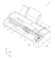
図1は、本発明の実施形態1に係る液体噴射装置の一例であるインクジェット式記録装置の斜視図である。
Hereinafter, the present invention will be described in detail based on embodiments.
(Embodiment 1)
FIG. 1 is a perspective view of an ink jet recording apparatus which is an example of a liquid ejecting apparatus according to
図1に示すインクジェット式記録装置Iにおいて、インクジェット式記録ヘッド1はキャリッジ3に搭載されている。図3に示すように、インクジェット式記録ヘッド1の一方面には、複数のノズル開口21が形成された液体噴射面20aが設けられている。本実施形態では、被噴射媒体である記録シートSの搬送方向を第1の方向Xと称する。また、キャリッジ3は、装置本体4に取り付けられたキャリッジ軸5に軸方向移動可能に設けられている。本実施形態では、キャリッジ軸5の軸方向、すなわち、キャリッジ3の移動方向を第1の方向Xに交差する第2の方向Yと称する。さらに、第1の方向X及び第2の方向Yの双方に交差する方向を、本実施形態では第3の方向Zと称する。なお、本実施形態では、説明理解を容易にするために、各方向(X、Y、Z)の関係を直交とするが、各構成の配置関係が必ずしも直交するものに限定されるべきものではない。
In the ink jet recording apparatus I shown in FIG. 1, the ink
キャリッジ3には、インクジェット式記録ヘッド1にインクを供給するためのインク貯留手段であるインクカートリッジ2が着脱可能に設けられている。なお、本実施形態では、インクカートリッジ2がキャリッジ3に搭載された構成を例示したが、特にこれに限定されず、インクタンク等の液体貯留手段を装置本体4に固定して、液体貯留手段とインクジェット式記録ヘッド1とをチューブ等の供給管を介して接続してもよい。
The
そして、駆動モーター6の駆動力が図示しない複数の歯車およびタイミングベルト7を介してキャリッジ3に伝達されることで、インクジェット式記録ヘッド1を搭載したキャリッジ3はキャリッジ軸5に沿って第2の方向Yに移動される。
Then, the driving force of the driving motor 6 is transmitted to the
一方、装置本体4には搬送手段としての搬送ローラー8が設けられており、紙等の記録媒体である記録シートSが搬送ローラー8により第1の方向Xに搬送されるようになっている。なお、記録シートSを搬送する搬送手段は、搬送ローラーに限られずベルトやドラム等であってもよい。 On the other hand, the apparatus main body 4 is provided with a conveyance roller 8 as a conveyance means, and a recording sheet S that is a recording medium such as paper is conveyed in the first direction X by the conveyance roller 8. Note that the conveyance means for conveying the recording sheet S is not limited to the conveyance roller, and may be a belt, a drum, or the like.
また、装置本体4のキャリッジ3の移動方向の一端部、すなわち、非印字領域には、電源オフ時やインクジェット式記録ヘッド1をメンテナンスする場合にキャリッジ3を位置させるためのメンテナンス位置となるホームポジションが設けられている。このホームポジションの第3の方向Zの下方となる位置には、インクジェット式記録ヘッド1からのインク滴の噴射が良好に維持されるように、各種メンテナンス動作を行うメンテナンスユニット200が設けられている。
Further, at one end of the apparatus body 4 in the moving direction of the
まず、本実施形態のインクジェット式記録ヘッド1について、図2〜図4を参照して説明する。なお、図2は、本実施形態の液体噴射ヘッドの一例であるインクジェット式記録ヘッドの分解斜視図であり、図3は、インクジェット式記録ヘッドの液体噴射面側の平面図であり、図4は、図3のA−A′線断面図、図5は、図3のB−B′線断面図である。
First, the ink
図示するように、インクジェット式記録ヘッド1は、流路部材130と、ヘッド本体140と、位置決め当接部であるカバーヘッド150と、を具備する。
As shown in the figure, the ink
流路部材130は、インクカートリッジが直接又は他の流路部材を介して装着されて、インクカートリッジ2のインクをヘッド本体140に供給するためのものである。このような流路部材130には、インクカートリッジ2のインクを各ヘッド本体140に供給する供給路131が設けられている。例えば、流路部材130に直接インクカートリッジ2が装着される場合には、供給路131の一端には、インク供給針等が設けられる。なお、図2に示す例では、インク供給針に代わって、流路部材130の第3の方向Zの一方面に内部に供給路131が設けられた円筒状の突起部を図示しているが、もちろんこれに限定されず、円錐状に先が尖ったインク供給針であってもよい。
The
ここで、ヘッド本体140についてさらに図6及び図7を参照して詳細に説明する。なお、図6は、ヘッド本体の分解斜視図であり、図7は、ヘッド本体の断面図である。
Here, the head
図示するように、本実施形態のヘッド本体140は、流路形成基板10、連通板15、ノズルプレート20、保護基板30及びケース部材等の複数の部材を備え、これら複数の部材が接着剤等によって接合されている。
As shown in the figure, the head
流路形成基板10は、ステンレス鋼やNiなどの金属、ZrO2あるいはAl2O3を代表とするセラミック材料、ガラスセラミック材料、MgO、LaAlO3のような酸化物などを用いることができる。本実施形態では、流路形成基板10は、シリコン単結晶基板からなる。この流路形成基板10には、一方面側から異方性エッチングすることにより、複数の隔壁によって区画された圧力発生室12がインクを吐出する複数のノズル開口21が並設される方向に沿って並設されている。本実施形態では、この方向を圧力発生室12の並設方向とも称し、上述したインクジェット式記録装置Iの第1の方向Xと一致する。すなわち、インクジェット式記録ヘッド1は、圧力発生室12(ノズル開口21)の並設方向が、第1の方向Xとなるようにインクジェット式記録装置Iに搭載される。また、流路形成基板10には、圧力発生室12が第1の方向Xに並設された列が複数列、本実施形態では、2列設けられている。この圧力発生室12が第1の方向Xに沿って形成された圧力発生室12の列が複数列設された列設方向は、第2の方向Yと一致する。
For the flow
また、流路形成基板10には、圧力発生室12の第2の方向Yの一端部側に、当該圧力発生室12よりも開口面積が狭く、圧力発生室12に流入するインクの流路抵抗を付与する供給路等が設けられていてもよい。
Further, the flow
また、流路形成基板10の一方面側(積層方向であって−Z方向)には、連通板15が接合されている。また、連通板15には、各圧力発生室12に連通する複数のノズル開口21が穿設されたノズルプレート20が接合されている。
A
連通板15には、圧力発生室12とノズル開口21とを連通するノズル連通路16が設けられている。連通板15は、流路形成基板10よりも大きな面積を有し、ノズルプレート20は流路形成基板10よりも小さい面積を有する。このようにノズルプレート20の面積を比較的小さくすることでコストの削減を図ることができる。なお、本実施形態では、ノズルプレート20のノズル開口21が開口されて、インク滴が吐出される面を液体噴射面20aと称する。また、本実施形態では、ノズルプレート20の液体噴射面20aが、特許請求の範囲に記載の「ノズル開口が形成された領域」に相当する。
The
また、連通板15には、マニホールド100の一部を構成する第1マニホールド部17と、第2マニホールド部(絞り流路、オリフィス流路)18とが設けられている。
Further, the
第1マニホールド部17は、連通板15を厚さ方向(連通板15と流路形成基板10との積層方向)に貫通して設けられている。
The
また、第2マニホールド部18は、連通板15を厚さ方向に貫通することなく、連通板15のノズルプレート20側に開口して設けられている。
Further, the
さらに、連通板15には、圧力発生室12の第2の方向Yの一端部に連通する供給連通路19が、各圧力発生室12毎に独立して設けられている。この供給連通路19は、第2マニホールド部18と圧力発生室12とを連通する。
Further, the
このような連通板15としては、ステンレスやNiなどの金属、またはジルコニウムなどのセラミックなどを用いることができる。なお、連通板15は、流路形成基板10と線膨張係数が同等の材料が好ましい。すなわち、連通板15として流路形成基板10と線膨張係数が大きく異なる材料を用いた場合、加熱や冷却されることで、流路形成基板10と連通板15との線膨張係数の違いにより反りが生じてしまう。本実施形態では、連通板15として流路形成基板10と同じ材料、すなわち、シリコン単結晶基板を用いることで、熱による反りや熱によるクラック、剥離等の発生を抑制することができる。
As the
また、ノズルプレート20には、各圧力発生室12とノズル連通路16を介して連通するノズル開口21が形成されている。すなわち、ノズル開口21は、同じ種類の液体(インク)を噴射するものが第1の方向Xに並設され、この第1の方向Xに並設されたノズル開口21の列(ノズル列)が第2の方向Yに2列形成されている。本実施形態では、ノズルプレート20のノズル開口21が開口する第3の方向Zの一方面を液体噴射面20aと称する。
The
このようなノズルプレート20としては、例えば、ステンレス鋼(SUS)等の金属、ポリイミド樹脂のような有機物、又はシリコン単結晶基板等を用いることができる。なお、ノズルプレート20としてシリコン単結晶基板を用いることで、ノズルプレート20と連通板15との線膨張係数を同等として、加熱や冷却されることによる反りや熱によるクラック、剥離等の発生を抑制することができる。
As such a
一方、流路形成基板10の連通板15とは反対面側には、振動板50が形成されている。本実施形態では、振動板50として、流路形成基板10側に設けられた酸化シリコンからなる弾性膜51と、弾性膜51上に設けられた酸化ジルコニウムからなる絶縁体膜52と、を設けるようにした。なお、圧力発生室12等の液体流路は、流路形成基板10を一方面側(ノズルプレート20が接合された面側)から異方性エッチングすることにより形成されており、圧力発生室12等の液体流路の他方面は、弾性膜51によって画成されている。
On the other hand, a
また、振動板50の絶縁体膜52上には、第1電極60と、圧電体層70と、第2電極80とが、本実施形態では、成膜及びリソグラフィー法によって積層形成されて圧電アクチュエーター300を構成している。ここで、圧電アクチュエーター300は、第1電極60、圧電体層70及び第2電極80を含む部分をいう。一般的には、圧電アクチュエーター300の何れか一方の電極を共通電極とし、他方の電極及び圧電体層70を各圧力発生室12毎にパターニングして構成する。そして、ここではパターニングされた何れか一方の電極及び圧電体層70から構成され、両電極への電圧の印加により圧電歪みが生じる部分を圧電体能動部という。本実施形態では、第1電極60を圧電アクチュエーター300の共通電極とし、第2電極80を圧電アクチュエーター300の個別電極としているが、駆動回路や配線の都合でこれを逆にしても支障はない。なお、上述した例では、第1電極60が、複数の圧力発生室12に亘って連続して設けられているため、第1電極60が振動板の一部として機能するが、勿論これに限定されるものではなく、例えば、上述の弾性膜51及び絶縁体膜52の何れか一方又は両方を設けずに、第1電極60のみが振動板として作用するようにしてもよい。
Further, on the
また、流路形成基板10の圧電アクチュエーター300側の面には、流路形成基板10と略同じ大きさを有する保護基板30が接合されている。保護基板30は、圧電アクチュエーター300を保護して収容するための空間である保持部31を有する。また、保護基板30には、厚さ方向である第3の方向Zに貫通する貫通孔32が設けられている。リード電極90の第2電極80に接続された一端部とは反対側の他端部は、この貫通孔32内に露出するように延設され、リード電極90と駆動IC等の駆動回路120を実装した配線基板121とが、貫通孔32内で電気的に接続されている。
A
また、このような構成のヘッド本体140には、複数の圧力発生室12に連通するマニホールド100をヘッド本体140と共に画成するケース部材40が固定されている。ケース部材40は、平面視において上述した連通板15と略同一形状を有し、保護基板30に接合されると共に、上述した連通板15にも接合されている。具体的には、ケース部材40は、保護基板30側に流路形成基板10及び保護基板30が収容される深さの凹部41を有する。この凹部41は、保護基板30の流路形成基板10に接合された面よりも広い開口面積を有する。そして、凹部41に流路形成基板10等が収容された状態で凹部41のノズルプレート20側の開口面が連通板15によって封止されている。これにより、流路形成基板10の外周部には、ケース部材40とヘッド本体140とによって第3マニホールド部42が画成されている。そして、連通板15に設けられた第1マニホールド部17及び第2マニホールド部18と、ケース部材40とヘッド本体140とによって画成された第3マニホールド部42と、によって本実施形態のマニホールド100が構成されている。
In addition, a
なお、ケース部材40の材料としては、例えば、樹脂や金属等を用いることができる。ちなみに、ケース部材40として、樹脂材料を成形することにより、低コストで量産することができる。
In addition, as a material of
また、連通板15の第1マニホールド部17及び第2マニホールド部18が開口する面には、コンプライアンス基板45が設けられている。このコンプライアンス基板45が、第1マニホールド部17と第2マニホールド部18の液体噴射面20a側の開口を封止している。
A
このようなコンプライアンス基板45は、本実施形態では、封止膜46と、固定基板47と、を具備する。封止膜46は、可撓性を有する薄膜(例えば、ポリフェニレンサルファイド(PPS)やステンレス鋼(SUS)等により形成された厚さが20μm以下の薄膜)からなり、固定基板47は、ステンレス鋼(SUS)等の金属等の硬質の材料で形成される。この固定基板47のマニホールド100に対向する領域は、厚さ方向に完全に除去された開口部48となっているため、マニホールド100の一方面は可撓性を有する封止膜46のみで封止された可撓部であるコンプライアンス部となっている。
In this embodiment, the
なお、ケース部材40には、マニホールド100に連通して各マニホールド100にインクを供給するための導入路44が設けられている。また、ケース部材40には、保護基板30の貫通孔32に連通して配線基板121が挿通される接続口43が設けられている。
The
このような構成のヘッド本体140では、インクを噴射する際に、インクカートリッジ2から流路部材130を介して導入路44からインクを取り込み、マニホールド100からノズル開口21に至るまで流路内部をインクで満たす。その後、駆動回路120からの信号に従い、圧力発生室12に対応する各圧電アクチュエーター300に電圧を印加することにより、圧電アクチュエーター300と共に振動板50をたわみ変形させる。これにより、圧力発生室12内の圧力が高まり所定のノズル開口21からインク滴が噴射される。
In the head
このようなヘッド本体140は、図2〜図5に示すように、上述した流路部材130にノズル列の並び方向、すなわち、第2の方向Yに所定の間隔で4つ固定されている。すなわち、本実施形態のインクジェット式記録ヘッド1には、ノズル開口21が並設されたノズル列が8列設けられていることになる。このように複数のヘッド本体140を用いてノズル列の多列化を図ることで、1つのヘッド本体140にノズル列を多列形成するのに比べて歩留まりの低下を防止することができる。また、ノズル列の多列化を図るために複数のヘッド本体140を用いることで、1枚のシリコンウェハから形成できるヘッド本体140の取り数を増大させることができ、シリコンウェハの無駄な領域を減少させて製造コストを低減することができる。
As shown in FIGS. 2 to 5, four
また、流路部材130に固定された4つのヘッド本体140の液体噴射面20a側は、本実施形態の当接部材であるカバーヘッド150によって覆われている。
Further, the
カバーヘッド150は、ヘッド本体140の液体噴射面20aを露出する露出開口部151と、露出開口部151を画成する接合部152と、を具備する。
The
露出開口部151は、各ヘッド本体140の液体噴射面20aを独立して露出するように、4つ形成されている。このような露出開口部151は、本実施形態では、ノズルプレート20を露出する大きさ、つまり、コンプライアンス基板45と同じ開口を有する。
Four
接合部152は、露出開口部151を画成すると共に、第2の方向Yで隣接するヘッド本体140の間の空間を塞ぐように設けられている。そして、接合部152が、コンプライアンス基板45の連通板15とは反対面側に接合されており、コンプライアンス部49の流路(マニホールド100)とは反対側の空間に蓋をする。
The joining
すなわち、本実施形態のノズル開口21が形成された領域であるノズルプレート20の液体噴射面20aの外側に、位置決め当接部であるカバーヘッド150が設けられており、カバーヘッド150は、液体噴射面20aの周囲を取り囲むように配置されている。また、カバーヘッド150の露出開口部151は、ノズルプレート20よりも大きな開口面積で形成されることで、露出開口部151の開口縁部と、ヘッド本体140のノズルプレート20との間には隙間が形成されている。本実施形態では、ノズルプレート20とカバーヘッド150の露出開口部151との間の隙間には、充填剤142が充填されている。充填剤142は、ノズルプレート20側では液体噴射面20aよりも低い位置(液体噴射方向とは反対方向)で、且つカバーヘッド150側ではカバーヘッド150の表面よりも低い位置となるように形成されている。これにより、詳しくは後述するが、キャップ本体210によってノズル開口21からインクを吸引した際などに、インクがノズルプレート20と露出開口部151の開口縁部との隙間に充填保持されて、保持されたインクが予期せぬタイミングで記録シートS上に落下して記録シートSを汚すのを抑制することができる。
That is, a
なお、充填剤142は、耐液体性を有する材料であれば、特に限定されず、例えば、接着剤などを用いることができる。また、充填剤142は、例えば、カバーヘッド150をコンプライアンス基板45に接着する接着剤の一部であってもよい。
Note that the
また、カバーヘッド150は、本実施形態では、ヘッド本体140の側面(液体噴射面20aとは交差する面)を覆うように、液体噴射面20a側から端部を屈曲して設けられた屈曲部153を有する。本実施形態では、液体噴射面20aの第1の方向Xの両側の側面と、第2の方向Yの両側の側面との合計4カ所に屈曲部153が設けられている。このように屈曲部153を設けることで、カバーヘッド150の剛性を向上して、カバーヘッド150の変形を抑制することができる。ちなみに、カバーヘッド150として、屈曲部153が設けられていない平板状の部材を用いた場合、カバーヘッド150の剛性が低くなるが、平板状の部材の周囲を屈曲して屈曲部153を設けることで、平板状のカバーヘッド150に比べてカバーヘッド150の剛性を向上することができる。特に、本実施形態では、詳しくは後述するが、メンテナンスユニットのキャップ本体210をカバーヘッドに当接させて位置決めするため、カバーヘッド150の剛性が低いと変形し易いが、屈曲部153を設けることで、キャップ本体210がカバーヘッド150に当接してもカバーヘッド150が変形し難くすることができる。また、屈曲部153の外側の面は、詳しくは後述するキャップ本体210の位置決め面が当接される当接面153aとなっている。
Further, in the present embodiment, the
このようなカバーヘッド150としては、例えば、ステンレス鋼などの金属材料や、セラミック材料、ガラスセラミック材料、酸化物などを用いることができる。
As such a
また、カバーヘッド150は、ヘッド本体140の液体噴射面20a側に接着剤141を介して接合されている。すなわち、4つのヘッド本体140は、1つのカバーヘッド150に共通して固定されている。このような接着剤141は、本実施形態では、ケース部材40と屈曲部153との間にも充填されて設けられている。これにより、カバーヘッドの剛性、特に屈曲部153の剛性が向上される。このため、詳しくは後述するが、キャップ本体210がカバーヘッド150の屈曲部153に当接した際に、屈曲部153が変形するのをさらに抑制することができる。なお、接着剤141は、全ての屈曲部153とケース部材40との間に設けることで、カバーヘッド150の剛性をさらに向上することができるが、少なくともキャップ本体210の側壁が当接する屈曲部153とケース部材40との間に接着剤141を充填すれば、キャップ本体210が当接することによるカバーヘッド150の変形を抑制することができる。
Further, the
このようなカバーヘッド150は、本実施形態では、インク(液体)の吐出方向において、ノズルプレート20の液体噴射面20aよりも記録シートS側に突出して設けられている。このように、カバーヘッド150を液体噴射面20aよりも記録シートS側に突出させることで、記録シートSがノズルプレート20に接触し難くなり、記録シートSがノズルプレート20に接触することによるノズルプレート20の変形及び剥離等の発生を抑制することができる。
In this embodiment, such a
そして、このようなインクジェット式記録ヘッド1は、上述したように、第2の方向Yがキャリッジ3の移動方向である主走査方向となるように、インクジェット式記録装置Iに搭載される。
Such an ink
一方、メンテナンスユニット200について、図8〜図11を参照して詳細に説明する。なお、図8は、本発明の実施形態1に係るキャップ本体の斜視図であり、図9は、キャップ本体の平面図であり、図10は、図9のC−C′線断面図であり、図11は、インクジェット式記録ヘッド及びキャップ本体の断面図である。
On the other hand, the
図示するように、メンテナンスユニット200は、略矩形箱状を有するキャップ本体210を備えており、キャップ本体210の上面側(第3の方向Z)には、複数の矩形環状を有するシール部材211がキャップ開口部を構成するように形成されている。シール部材211は、本実施形態では、4つのヘッド本体140の液体噴射面20aを覆う大きさで形成されている。すなわち、シール部材211は、本実施形態では、位置決め当接部であるカバーヘッド150の第3の方向Zの記録シートS側の面に当接する大きさで形成されている。つまり、シール部材211は、カバーヘッド150に設けられた4つの露出開口部151を内包する大きさで形成されている。これにより、シール部材211は、カバーヘッド150の接合部152の記録シートS側の面に当接して、キャップ本体210の内側に密封空間212(図11参照)を形成する。なお、シール部材211は、ヘッド本体140毎に個別に設けられていてもよい。すなわち、4つの露出開口部151毎に独立した密封空間212を形成する4つのシール部材211が設けられていてもよい。
As shown in the figure, the
また、キャップ本体210には、第3の方向Zにおいてインクジェット式記録ヘッド1側に突出する側壁213を有する。側壁213は、本実施形態では、キャップ本体210の搬送方向である第1の方向Xの一方側に第3の方向Zに突出して設けられている。このような側壁213は、シール部材211側に開口する凹部214が第3の方向Zに沿って設けられており、側壁213の凹部214の両側、すなわち、第2の方向Yの両側には、2つの位置決め面215が設けられている。
The
なお、キャップ本体210のシール部材211側の内側には、凹形状を有するホルダー部216が設けられている。ホルダー部216には、特に図示していないが、多孔質材料等で形成された液体吸収材等が保持されており、ノズル開口21から吸引したインクを吸収保持するようになっている。
In addition, a
また、メンテナンスユニット200には、キャップ本体210を第3の方向Zに昇降させるための昇降装置(図示なし)を備えている。そして、キャリッジ3をホームポジションに移動させた状態で、昇降装置によりキャップ本体210を第3の方向Zに上昇させることで、シール部材211の上端がインクジェット式記録ヘッド1のカバーヘッド150に密接され、全てのノズル開口21がキャップ本体210のシール部材211に覆われる。また、昇降装置(図示なし)は、キャップ本体210をインクジェット式記録ヘッド1に対して第2の方向Yに移動可能に設けられており、昇降装置によってキャップ本体210が移動されることで、キャップ本体210はインクジェット式記録ヘッド1に対して第2の方向Yの位置決めが行われる。
In addition, the
具体的には、インクジェット式記録ヘッド1とキャップ本体210との液体噴射面20aの面内方向のうち、本実施形態の第2の方向Yの位置決めは、カバーヘッド150の屈曲部153の外側の当接面153aに、側壁213のシール部材211側の内面である2つの位置決め面215を当接させることで行われる。つまり、キャップ本体210を第2の方向Yに移動させて、側壁213の位置決め面215をカバーヘッド150の屈曲部153の第2の方向Yの外側の当接面153aに面接触させる。これにより、キャップ本体210とカバーヘッド150との第2の方向Yの位置が規定される。すなわち、側壁213の位置決め面215とシール部材211とは互いに位置決めされており、位置決め面215をカバーヘッド150の当接面153aに当接させることで、シール部材211のカバーヘッド150の当接位置への位置決めを高精度に行うことができる。つまり、シール部材211は、キャップ本体210の側壁213と、カバーヘッド150の屈曲部153とを介してカバーヘッド150の接合部152に位置決めされる。このため、キャップ本体210のシール部材211をカバーヘッド150に高精度に位置決めすることができる。
Specifically, among the in-plane directions of the liquid ejection surface 20 a between the ink
これに対して、例えば、シール部材211をノズルプレート20の液体噴射面20aに直接当接させようとすると、シール部材211は、ノズルプレート20に至るまで、キャップ本体210と、カバーヘッド150と、コンプライアンス基板45と、連通板15との4つの部材が間に介在するため、各部材の寸法公差及び相互の位置決め誤差が積算されて、シール部材が当接する位置に大きな誤差が生じ易い。そして、シール部材211が当接する位置に大きな誤差が生じると、シール部材211で全てのノズル開口21を確実に覆うことができずに、ノズル開口21のクリーニング不良等が発生する虞がある。また、シール部材211の位置ずれしても全てのノズル開口21を確実に覆うためには、シール部材211が当接する領域を予め広く取る必要があり、ノズルプレート20が大型化してインクジェット式記録ヘッド1が大型化してしまう。特に、液体噴射面20aの記録シートSの搬送方向である第1の方向Xを大型化してしまうと、記録シートSの搬送方向において、インクジェット式記録ヘッド1を挟んで設けられた図示しない搬送手段の距離が遠くなり、記録シートSの固定の制御が困難になる。本実施形態では、シール部材211は、当接するカバーヘッド150に至るまでに、キャップ本体210の1つの部材しか介在しないため、部品の寸法公差及び相互の位置決め誤差が積算されたとしても大きな誤差が生じ難い。したがって、インクジェット式記録ヘッド1に対してシール部材211の位置ずれを考慮して当接する領域を広く配置する必要がなく、インクジェット式記録ヘッド1の小型化を図ることができる。特に、本実施形態では、搬送方向である第1の方向Xにおいて、シール部材211とインクジェット式記録ヘッド1との高精度な位置決めを行うことができるため、インクジェット式記録ヘッド1を挟んで設けられた図示しない搬送手段の距離を短くして、記録シートSの固定の制御を容易に行って、着弾位置ずれ等による印刷不良を抑制することができると共に、搬送手段の大型化を抑制してインクジェット式記録装置Iを小型化することができる。
On the other hand, for example, when the
また、本実施形態では、2つの位置決め面215を設け、第2の方向Yの一方に設けられた屈曲部153の当接面153aの第1の方向Xの両端側に当接するようにしたため、シール部材211の回転方向の高精度な位置決めを行うことができる。ちなみに、位置決め面215を当接面153aの全面に亘って当接する大きさで形成することも可能であるが、位置決め面215の面積が大きくなれば、それだけ高い面精度で位置決め面215を形成するのは困難である。また、面積の小さな位置決め面215を1つだけ設けた場合、位置決め面215が当接面153aに当接した状態で、当接した部分を支点とした回転方向の位置決め精度が低下してしまう虞がある。本実施形態では、第1の方向Xで離れた位置で1つの当接面153aに当接する2つの位置決め面215を設けることで、位置決め面215の面積を減少させて、高い面精度で容易に形成することができると共に、回転方向の位置決め精度を向上することができる。
Further, in the present embodiment, since the two
なお、キャップ本体210のホルダー部216には、図示しない吸引ポンプ等の吸引手段が接続されており、キャップ本体210は、シール部材211をカバーヘッド150に当接させて、ホルダー部216に連通する密封空間212を形成して、密封した後、吸引手段の吸引によってホルダー部216及び密封空間212内を負圧として、ノズル開口21からインクジェット式記録ヘッド1の流路内のインクを気泡と共に吸引して吸引動作(クリーニング動作)を行う。また、非印刷時には、キャップ本体210のシール部材211によってノズル開口21を覆うことにより、ノズル開口21近傍のインクの乾燥を抑制するようにしてもよい。
Note that suction means such as a suction pump (not shown) is connected to the
また、本実施形態では、側壁213の位置決め面215が当接するカバーヘッド150の屈曲部153は、ケース部材40との間に接着剤141が充填されているため、屈曲部153の剛性が向上されている。したがって、屈曲部153に位置決め面215が当接することによって、屈曲部153の変形、すなわち、屈曲部153の角度が変わるのを抑制して、屈曲部153の変形による位置ずれを抑制することができる。また、位置決め面215が当接面153aに面接触するため、キャップ本体210の側壁213及びカバーヘッド150が互いに接触することによって削られることや破損するのを抑制して、両者の破損による位置ずれを抑制して、高精度な位置決めを長期間維持することができる。
In the present embodiment, the bending
なお、メンテナンスユニット200には、特に図示していないが、液体噴射面20aやカバーヘッド150の記録シートS側の面を払拭するゴム等の弾性部材で形成されたブレード部材等が設けられていてもよい。このようなブレード部材を設けることで、キャップ本体210によるインクジェット式記録ヘッド1のキャッピングが行われた後、ブレード部材によって液体噴射面20aを払拭することで、ノズル開口21のインクのメニスカスを良好に保つことができる。
Although not particularly illustrated, the
(実施形態2)
図12は、本発明の実施形態2に係る液体噴射ヘッドの一例であるインクジェット式記録ヘッド及びキャップ本体の断面図である。なお、上述した実施形態1と同様の部材には同一の符号を付して重複する説明は省略する。
(Embodiment 2)
FIG. 12 is a cross-sectional view of an ink jet recording head and a cap body which are an example of a liquid jet head according to Embodiment 2 of the present invention. In addition, the same code | symbol is attached | subjected to the member similar to
図12に示すように、位置決め当接部であるカバーヘッド150の屈曲部153は、第3の方向Zに対して傾斜した方向に屈曲されて設けられている。本実施形態では、屈曲部153は、液体噴射面20aから離れるに従って、ケース部材40から離れる方向に屈曲して設けられている。また、本実施形態の屈曲部153とケース部材40との間には、上述した実施形態1と同様に接着剤141が充填されており、屈曲部153の剛性は接着剤141によって向上されている。
As shown in FIG. 12, the
このようなインクジェット式記録ヘッド1にキャップ本体210を位置決めする際には、側壁213の位置決め面215を屈曲部153の先端、すなわち、屈曲部153の液体噴射面20aとは反対側の端部に接触させることで行われる。このとき、位置決め面215と屈曲部153とは面接触ではなく線接触するため、屈曲部153に対するキャップ本体210の位置決めを高精度に行うことができる。すなわち、上述した実施形態1のように位置決め面215と屈曲部153の当接面153aとを面接触させて位置決めさせる場合、位置決め面215と当接面153aとを高い面精度で形成しなくてはならないが、本実施形態では、位置決め面215と屈曲部153とを面接触ではなく線接触させることで、屈曲部153の高い面精度が不要となる。したがって、先端部の位置の精度のみを高精度に規定すればいいため、製造工程を簡略化して、高い精度でキャップ本体210のシール部材211とカバーヘッド150とを位置決めすることができる。
When positioning the
なお、本実施形態では、屈曲部153を液体噴射面20aから第3の方向Zのケース部材40側に行くに従って、ケース部材40から離れる角度で屈曲したが、特にこれに限定されない。例えば、図13に示すように、屈曲部153が、液体噴射面20aから第3の方向Zのケース部材40側に行くに従い、ケース部材40に近づくように屈曲されていてもよい。このような場合であっても、位置決め面と屈曲部153の液体噴射面20a側、すなわち、屈曲部153と接合部152との屈曲した領域とを線接触させることができ、上述した構成と同じ効果を奏することができる。
In the present embodiment, the
(実施形態3)
図14は、本発明の液体噴射ヘッドの一例であるインクジェット式記録ヘッド及びキャップ本体の断面図である。なお、上述した実施形態と同様の部材には同一の符号を付して重複する説明は省略する。
(Embodiment 3)
FIG. 14 is a cross-sectional view of an ink jet recording head and a cap body which are examples of the liquid jet head of the present invention. In addition, the same code | symbol is attached | subjected to the member similar to embodiment mentioned above, and the overlapping description is abbreviate | omitted.
図14に示すように、インクジェット式記録ヘッド1のカバーヘッド150には、屈曲部153が設けられていない。ただし、接合部152は、流路部材130の液体噴射面20a側の面よりも大きな面積で形成されており、第2の方向Yにおいて流路部材130より第2の方向Yに突出して設けられている。
As shown in FIG. 14, the
また、接合部152と流路部材130とで形成された角部には、接着剤141が設けられており、接合部152の流路部材130よりも突出した領域は、接着剤141によって剛性が向上されている。
In addition, an adhesive 141 is provided at a corner portion formed by the
このようなインクジェット式記録ヘッド1のカバーヘッド150には、キャップ本体210の側壁213の位置決め面215が当接する。すなわち、位置決め面215は、カバーヘッド150の接合部152の端部に当接する。このような構成であっても、カバーヘッド150に対してシール部材211を高精度に位置決めすることができる。
The
(他の実施形態)
以上、本発明の各実施形態について説明したが、本発明の基本的な構成は上述したものに限定されるものではない。
(Other embodiments)
As mentioned above, although each embodiment of this invention was described, the fundamental structure of this invention is not limited to what was mentioned above.
例えば、上述した実施形態1〜3のインクジェット式記録ヘッド1は、位置決め当接部であるカバーヘッド150とノズルプレート20との間に隙間を形成し、両者が互いに接合されていない構成を例示したが、特にこれに限定されない。ここで、インクジェット式記録ヘッドの他の例を図15に示す。なお、図15は、他の実施形態に係るインクジェット式記録ヘッドの断面図である。
For example, the inkjet recording heads 1 of
図15に示すように、インクジェット式記録ヘッド1は、流路形成基板10に直接ノズルプレート20が接合されている。すなわち、流路形成基板10とノズルプレート20との間に連通板15が設けられておらず、流路形成基板10の圧電アクチュエーター300とは反対側の開口はノズルプレート20によって封止されている。このような流路形成基板10には、圧力発生室12と、マニホールドの一部を構成する第1マニホールド部13と、第1マニホールド部13と圧力発生室12とを連通するインク供給路14a及び連通路14bとが設けられている。インク供給路14aは、圧力発生室12よりも第1の方向Xの幅が狭い幅で形成されており、第1マニホールド部13から圧力発生室12に流入するインクの流路抵抗を一定に保持している。連通路14bは、第1の方向Xの断面積が圧力発生室12と略同じ断面積となる大きさで形成されている。これら、圧力発生室12、第1マニホールド部13、インク供給路14a、連通路14bは、流路形成基板10を厚さ方向である第3の方向Zに貫通して設けられており、一方の開口はノズルプレート20によって封止され、他方の開口は振動板50によって封止されている。
As shown in FIG. 15, in the ink
また、流路形成基板10の圧電アクチュエーター300側の面には、保護基板30が接合されている。保護基板30には、マニホールド100の一部を構成する第2マニホールド部33が形成されている。第2マニホールド部33は、保護基板30を厚さ方向に貫通して設けられており、流路形成基板10の第1マニホールド部13と、保護基板30の第2マニホールド部33とで本実施形態のマニホールド100が構成されている。
A
また、保護基板30上には、マニホールド100を封止するコンプライアンス基板45が設けられている。
A
そして、ノズルプレート20には、上述した実施形態1〜3と同様に、露出開口部151が設けられたカバーヘッド150が接合されている。すなわち、図15に示す例では、カバーヘッド150は、ノズルプレート20の液体噴射面20aに接合されている。
Then, the
このような構成では、カバーヘッド150の露出開口部151によって露出されたノズルプレート20の液体噴射面20aの一部が、特許請求の範囲に記載の「ノズル開口が形成された領域」に相当する。すなわち、ノズル開口21が形成された領域と、位置決め当接部とは、上述した実施形態1〜3のように、隙間を介在させて離して配置されている構成も、図15に示すように、接触して直接連続している構成も含むものである。
In such a configuration, a part of the
また、上述した例では、位置決め当接部として、カバーヘッド150を例示したが、特にこれに限定されず、位置決め当接部がノズルプレート20であってもよい。すなわち、ノズルプレート20の一部を延設して、延設したノズルプレート20の一部が、キャップ本体210の側壁213に当接されるようにしてもよい。この場合には、キャップ本体210のシール部材211は当然ノズルプレート20の記録シートS側の面、すなわち液体噴射面20aに直接当接して密封空間212を形成すればよい。
In the above-described example, the
また、上述した各実施形態では、インクジェット式記録ヘッド1が搭載されたキャリッジ3が、第2の方向Yのホームポジションに移動した後、キャップ本体210が、第1の方向Xに移動して、側壁213をインクジェット式記録ヘッド1のカバーヘッド150に当接させるようにしたが、特にこれに限定されず、例えば、インクジェット式記録ヘッド1の移動によってキャップ本体210の側壁213にカバーヘッド150を当接させるようにしてもよい。また、側壁213の位置は特に限定されず、キャリッジ3の移動方向である第2の方向Yの一方側に設けるようにしてもよい。また、第1の方向Xの一方側と、第2の方向Yの一方側との2カ所に側壁213を設けることで、キャップ本体210とインクジェット式記録ヘッド1との第1の方向X及び第2の方向Yの高精度な位置決めも可能である。
In each of the above-described embodiments, after the
さらに、上述した各実施形態のインクジェット式記録装置Iは、インクジェット式記録ヘッド1がキャリッジ3に搭載されて主走査方向に移動するものを例示したが、特にこれに限定されず、例えば、インクジェット式記録ヘッド1が固定されて、紙等の記録シートSを副走査方向に移動させるだけで印刷を行う、所謂ライン式記録装置にも本発明を適用することができる。
Further, the ink jet recording apparatus I of each of the above-described embodiments is exemplified by the ink
また、上述した各実施形態では、圧力発生室12に圧力変化を生じさせる圧力発生手段として、薄膜型の圧電アクチュエーター300を用いて説明したが、特にこれに限定されず、例えば、グリーンシートを貼付する等の方法により形成される厚膜型の圧電アクチュエーターや、圧電材料と電極形成材料とを交互に積層させて軸方向に伸縮させる縦振動型の圧電アクチュエーターなどを使用することができる。また、圧力発生手段として、圧力発生室内に発熱素子を配置して、発熱素子の発熱で発生するバブルによってノズル開口から液滴を吐出するものや、振動板と電極との間に静電気を発生させて、静電気力によって振動板を変形させてノズル開口から液滴を吐出させるいわゆる静電式アクチュエーターなどを使用することができる。
Further, in each of the embodiments described above, the thin
さらに、本発明は、広く液体噴射ヘッドを具備する液体噴射装置全般を対象としたものであり、例えば、プリンター等の画像記録装置に用いられる各種のインクジェット式記録ヘッド等の記録ヘッド、液晶ディスプレイ等のカラーフィルターの製造に用いられる色材噴射ヘッド、有機ELディスプレイ、FED(電界放出ディスプレイ)等の電極形成に用いられる電極材料噴射ヘッド、バイオchip製造に用いられる生体有機物噴射ヘッド等を用いた液体噴射装置にも用いることが可能である。 Furthermore, the present invention is intended for a wide range of liquid ejecting apparatuses having a wide liquid ejecting head. For example, recording heads such as various ink jet recording heads used in image recording apparatuses such as printers, liquid crystal displays, and the like Liquid using a color material ejecting head, an organic EL display, an electrode material ejecting head used for forming an electrode such as an FED (field emission display), a bio-organic matter ejecting head used for biochip production, etc. It can also be used for an injection device.
I インクジェット式記録装置(液体噴射装置)、 1 インクジェット式記録ヘッド(液体噴射ヘッド)、 10 流路形成基板、 20 ノズルプレート、 20a 液体噴射面、 21 ノズル開口、 30 保護基板、 40 ケース部材、 100 マニホールド、 120 駆動回路、 121 配線基板、 130 流路部材、 140 ヘッド本体、 141 接着剤、 150 カバーヘッド(位置決め当接部)、 151 露出開口部、 152 接合部、 153 屈曲部、 153a 当接面、 200 メンテナンスユニット、 210 キャップ本体、 211 シール部材、 212 密封空間、 213 側壁、 214 凹部、 215 位置決め面、 216 ホルダー部、 300 圧電アクチュエーター(圧力発生手段) I ink jet recording apparatus (liquid ejecting apparatus), 1 ink jet recording head (liquid ejecting head), 10 flow path forming substrate, 20 nozzle plate, 20a liquid ejecting surface, 21 nozzle opening, 30 protective substrate, 40 case member, 100 Manifold, 120 drive circuit, 121 wiring board, 130 flow path member, 140 head main body, 141 adhesive, 150 cover head (positioning contact portion), 151 exposed opening, 152 joint portion, 153 bent portion, 153a contact surface , 200 maintenance unit, 210 cap body, 211 sealing member, 212 sealing space, 213 side wall, 214 recess, 215 positioning surface, 216 holder part, 300 piezoelectric actuator (pressure generating means)
Claims (5)
前記液体噴射ヘッドと相対的に移動可能に配置され、前記液体噴射面と交差した方向に起立する側壁を有するキャップ本体と、
前記キャップ本体の内側に収容配置され、前記液体噴射ヘッドと前記キャップ本体との相対的な移動によって前記領域を取り囲んだ状態で前記位置決め当接部と前記側壁とが当接して、前記キャップ本体の内側に密封空間を形成するシール部材と、
を備え、
前記キャップ本体の前記側壁が、前記液体噴射面の面方向に沿った方向のうちの一方で前記位置決め当接部と当接することで、前記液体噴射ヘッドと前記シール部材との前記液体噴射面に沿った方向の相対位置が規定され、
前記カバーは、前記液体噴射面の面方向に沿った方向のうちの一方に対応する端部において、屈曲部を有し、
前記屈曲部と前記流路部材との間には、充填剤が充填されており、
前記側壁は、前記位置決め当接部に当接する位置決め面を有し、
前記屈曲部は、前記側壁の前記位置決め面に対して傾斜して設けられていることを特徴とする液体噴射装置。 A head body having a liquid ejection surface in which nozzle openings for ejecting liquid are formed , a flow path member, and a cover that is a positioning contact portion disposed outside a region in which the plurality of nozzle openings are formed. A liquid jet head having
A cap body that is arranged to be movable relative to the liquid ejecting head and has a side wall that rises in a direction intersecting the liquid ejecting surface;
The positioning contact portion and the side wall are in contact with each other in a state of being housed and disposed inside the cap body and surrounding the region by relative movement of the liquid ejecting head and the cap body. A sealing member that forms a sealed space inside;
With
The side wall of the cap body abuts on the positioning contact portion in one of the directions along the surface direction of the liquid ejecting surface, so that the liquid ejecting surface of the liquid ejecting head and the seal member is brought into contact with the liquid ejecting surface. Relative position in the direction along
The cover has a bent portion at an end corresponding to one of the directions along the surface direction of the liquid ejection surface,
Between the bent portion and the flow path member is filled with a filler ,
The side wall has a positioning surface that contacts the positioning contact portion,
The liquid ejecting apparatus according to claim 1, wherein the bent portion is provided to be inclined with respect to the positioning surface of the side wall .
Priority Applications (4)
| Application Number | Priority Date | Filing Date | Title |
|---|---|---|---|
| JP2014039406A JP6365819B2 (en) | 2014-02-28 | 2014-02-28 | Liquid ejector |
| CN201510077165.3A CN104875491B (en) | 2014-02-28 | 2015-02-12 | Liquid injection apparatus |
| US14/627,077 US9434168B2 (en) | 2014-02-28 | 2015-02-20 | Liquid ejecting apparatus |
| US15/232,472 US9550361B2 (en) | 2014-02-28 | 2016-08-09 | Liquid ejecting apparatus |
Applications Claiming Priority (1)
| Application Number | Priority Date | Filing Date | Title |
|---|---|---|---|
| JP2014039406A JP6365819B2 (en) | 2014-02-28 | 2014-02-28 | Liquid ejector |
Publications (3)
| Publication Number | Publication Date |
|---|---|
| JP2015163436A JP2015163436A (en) | 2015-09-10 |
| JP2015163436A5 JP2015163436A5 (en) | 2017-04-06 |
| JP6365819B2 true JP6365819B2 (en) | 2018-08-01 |
Family
ID=53943282
Family Applications (1)
| Application Number | Title | Priority Date | Filing Date |
|---|---|---|---|
| JP2014039406A Active JP6365819B2 (en) | 2014-02-28 | 2014-02-28 | Liquid ejector |
Country Status (3)
| Country | Link |
|---|---|
| US (2) | US9434168B2 (en) |
| JP (1) | JP6365819B2 (en) |
| CN (1) | CN104875491B (en) |
Families Citing this family (2)
| Publication number | Priority date | Publication date | Assignee | Title |
|---|---|---|---|---|
| JP6991804B2 (en) * | 2017-09-11 | 2022-01-13 | ローランドディー.ジー.株式会社 | Printing equipment |
| JP7159018B2 (en) * | 2018-11-22 | 2022-10-24 | 東芝テック株式会社 | LIQUID EJECTION HEAD AND LIQUID EJECTION APPARATUS |
Family Cites Families (21)
| Publication number | Priority date | Publication date | Assignee | Title |
|---|---|---|---|---|
| EP0541519B1 (en) * | 1988-09-07 | 1997-01-22 | Seiko Epson Corporation | Ink jet printer sealing method and apparatus |
| JPH1134347A (en) * | 1997-07-24 | 1999-02-09 | Oki Data:Kk | Ink jet recorder |
| US6481826B1 (en) * | 1999-09-07 | 2002-11-19 | Seiko Epson Corporation | Ink jet recording apparatus, method of discharging ink from capping unit incorporated in the apparatus, and ink composition used with the apparatus |
| JP4178727B2 (en) * | 1999-09-07 | 2008-11-12 | セイコーエプソン株式会社 | Inkjet recording device |
| JP2003175617A (en) * | 2001-08-28 | 2003-06-24 | Ricoh Co Ltd | Ink-jet recording apparatus and copying apparatus |
| JP3827302B2 (en) * | 2002-06-07 | 2006-09-27 | キヤノン株式会社 | Inkjet recording device |
| CN2703646Y (en) * | 2002-06-21 | 2005-06-08 | 精工爱普生株式会社 | Liquid spraying device |
| US6722756B2 (en) * | 2002-07-01 | 2004-04-20 | Hewlett-Packard Development Company, L.P. | Capping shroud for fluid ejection device |
| JP3733936B2 (en) * | 2002-08-21 | 2006-01-11 | セイコーエプソン株式会社 | Liquid ejecting apparatus and liquid ejecting head |
| JP4168770B2 (en) * | 2003-02-06 | 2008-10-22 | セイコーエプソン株式会社 | Liquid ejector |
| US7284818B2 (en) * | 2003-04-04 | 2007-10-23 | Sieko Epson Corporation | Liquid injection apparatus |
| JP2006205495A (en) * | 2005-01-27 | 2006-08-10 | Canon Inc | Inkjet recorder |
| CN100475538C (en) * | 2005-03-29 | 2009-04-08 | 精工爱普生株式会社 | Head capping device and liquid ejecting apparatus incorporating the same |
| JP5050521B2 (en) * | 2006-01-19 | 2012-10-17 | セイコーエプソン株式会社 | Liquid ejecting head and liquid ejecting apparatus |
| JP4311472B2 (en) * | 2007-04-26 | 2009-08-12 | セイコーエプソン株式会社 | Fluid ejecting apparatus and method for controlling the apparatus |
| JP5444866B2 (en) * | 2009-06-18 | 2014-03-19 | セイコーエプソン株式会社 | Liquid discharge head, liquid discharge device, and method of manufacturing liquid discharge head |
| JP5333130B2 (en) | 2009-09-30 | 2013-11-06 | ブラザー工業株式会社 | Recording device |
| JP5786566B2 (en) * | 2011-08-31 | 2015-09-30 | セイコーエプソン株式会社 | Liquid ejector |
| JP5884377B2 (en) * | 2011-09-30 | 2016-03-15 | セイコーエプソン株式会社 | Liquid ejecting head and liquid ejecting apparatus |
| JP5935338B2 (en) * | 2012-01-16 | 2016-06-15 | 株式会社リコー | Image forming apparatus |
| JP6008102B2 (en) * | 2012-08-17 | 2016-10-19 | セイコーエプソン株式会社 | Liquid ejector |
-
2014
- 2014-02-28 JP JP2014039406A patent/JP6365819B2/en active Active
-
2015
- 2015-02-12 CN CN201510077165.3A patent/CN104875491B/en active Active
- 2015-02-20 US US14/627,077 patent/US9434168B2/en not_active Expired - Fee Related
-
2016
- 2016-08-09 US US15/232,472 patent/US9550361B2/en active Active
Also Published As
| Publication number | Publication date |
|---|---|
| US20150246541A1 (en) | 2015-09-03 |
| US9550361B2 (en) | 2017-01-24 |
| US9434168B2 (en) | 2016-09-06 |
| JP2015163436A (en) | 2015-09-10 |
| CN104875491B (en) | 2017-07-18 |
| CN104875491A (en) | 2015-09-02 |
| US20160347067A1 (en) | 2016-12-01 |
Similar Documents
| Publication | Publication Date | Title |
|---|---|---|
| JP4573022B2 (en) | Liquid jet head unit | |
| JP6028944B2 (en) | Liquid ejector | |
| JP6098267B2 (en) | Liquid ejecting head and liquid ejecting apparatus | |
| JP2014034114A (en) | Liquid jetting head and liquid jetting device | |
| JP2015217516A (en) | Liquid injection head unit and liquid injection device | |
| JP6115236B2 (en) | Liquid ejecting head, liquid ejecting apparatus, and fixing method | |
| US9855751B2 (en) | Method for manufacturing liquid ejecting head | |
| JP2010099872A (en) | Liquid jetting head and liquid jetting apparatus | |
| JP6183586B2 (en) | Liquid ejecting apparatus and liquid ejecting apparatus cleaning method | |
| JP6365819B2 (en) | Liquid ejector | |
| JP6288439B2 (en) | Liquid ejecting head, liquid ejecting apparatus, and method of manufacturing liquid ejecting head | |
| JP2016185600A (en) | Ink jet head and ink jet printer | |
| JP6292396B2 (en) | Liquid ejecting head, liquid ejecting apparatus, and method of manufacturing liquid ejecting head | |
| US20160271956A1 (en) | Liquid ejection head and liquid ejection apparatus | |
| JP6361858B2 (en) | Liquid ejector | |
| JP6256641B2 (en) | Liquid ejecting head and liquid ejecting apparatus | |
| JP6315177B2 (en) | Liquid ejector | |
| JP6292392B2 (en) | Liquid ejecting head and liquid ejecting apparatus | |
| JP6436281B2 (en) | Liquid ejecting head and liquid ejecting apparatus | |
| JP2016172335A (en) | Liquid jet device | |
| JP4363458B2 (en) | Liquid ejecting head unit and liquid ejecting apparatus | |
| JP2018069675A (en) | Liquid jetting head and liquid jetting device | |
| JP2010017856A (en) | Liquid jet head, liquid jet apparatus equipped with the same and method of replacing nozzle | |
| JP6347300B2 (en) | Liquid jet head | |
| US9346272B2 (en) | Liquid ejecting head and liquid ejecting apparatus |
Legal Events
| Date | Code | Title | Description |
|---|---|---|---|
| A521 | Request for written amendment filed |
Free format text: JAPANESE INTERMEDIATE CODE: A523 Effective date: 20170222 |
|
| A621 | Written request for application examination |
Free format text: JAPANESE INTERMEDIATE CODE: A621 Effective date: 20170222 |
|
| A131 | Notification of reasons for refusal |
Free format text: JAPANESE INTERMEDIATE CODE: A131 Effective date: 20170927 |
|
| A521 | Request for written amendment filed |
Free format text: JAPANESE INTERMEDIATE CODE: A523 Effective date: 20171122 |
|
| A131 | Notification of reasons for refusal |
Free format text: JAPANESE INTERMEDIATE CODE: A131 Effective date: 20180418 |
|
| A521 | Request for written amendment filed |
Free format text: JAPANESE INTERMEDIATE CODE: A523 Effective date: 20180529 |
|
| TRDD | Decision of grant or rejection written | ||
| A01 | Written decision to grant a patent or to grant a registration (utility model) |
Free format text: JAPANESE INTERMEDIATE CODE: A01 Effective date: 20180606 |
|
| A61 | First payment of annual fees (during grant procedure) |
Free format text: JAPANESE INTERMEDIATE CODE: A61 Effective date: 20180619 |
|
| R150 | Certificate of patent or registration of utility model |
Ref document number: 6365819 Country of ref document: JP Free format text: JAPANESE INTERMEDIATE CODE: R150 |