JP6991804B2 - Printing equipment - Google Patents
Printing equipment Download PDFInfo
- Publication number
- JP6991804B2 JP6991804B2 JP2017173969A JP2017173969A JP6991804B2 JP 6991804 B2 JP6991804 B2 JP 6991804B2 JP 2017173969 A JP2017173969 A JP 2017173969A JP 2017173969 A JP2017173969 A JP 2017173969A JP 6991804 B2 JP6991804 B2 JP 6991804B2
- Authority
- JP
- Japan
- Prior art keywords
- head
- mounting frame
- transport
- carriage
- cap
- Prior art date
- Legal status (The legal status is an assumption and is not a legal conclusion. Google has not performed a legal analysis and makes no representation as to the accuracy of the status listed.)
- Active
Links
Images


Classifications
-
- B—PERFORMING OPERATIONS; TRANSPORTING
- B41—PRINTING; LINING MACHINES; TYPEWRITERS; STAMPS
- B41J—TYPEWRITERS; SELECTIVE PRINTING MECHANISMS, i.e. MECHANISMS PRINTING OTHERWISE THAN FROM A FORME; CORRECTION OF TYPOGRAPHICAL ERRORS
- B41J2/00—Typewriters or selective printing mechanisms characterised by the printing or marking process for which they are designed
- B41J2/005—Typewriters or selective printing mechanisms characterised by the printing or marking process for which they are designed characterised by bringing liquid or particles selectively into contact with a printing material
- B41J2/01—Ink jet
- B41J2/135—Nozzles
- B41J2/165—Prevention or detection of nozzle clogging, e.g. cleaning, capping or moistening for nozzles
- B41J2/16505—Caps, spittoons or covers for cleaning or preventing drying out
- B41J2/16508—Caps, spittoons or covers for cleaning or preventing drying out connected with the printer frame
- B41J2/16511—Constructions for cap positioning
-
- B—PERFORMING OPERATIONS; TRANSPORTING
- B41—PRINTING; LINING MACHINES; TYPEWRITERS; STAMPS
- B41J—TYPEWRITERS; SELECTIVE PRINTING MECHANISMS, i.e. MECHANISMS PRINTING OTHERWISE THAN FROM A FORME; CORRECTION OF TYPOGRAPHICAL ERRORS
- B41J2/00—Typewriters or selective printing mechanisms characterised by the printing or marking process for which they are designed
- B41J2/005—Typewriters or selective printing mechanisms characterised by the printing or marking process for which they are designed characterised by bringing liquid or particles selectively into contact with a printing material
- B41J2/01—Ink jet
- B41J2/135—Nozzles
- B41J2/165—Prevention or detection of nozzle clogging, e.g. cleaning, capping or moistening for nozzles
- B41J2/16517—Cleaning of print head nozzles
- B41J2/1652—Cleaning of print head nozzles by driving a fluid through the nozzles to the outside thereof, e.g. by applying pressure to the inside or vacuum at the outside of the print head
- B41J2/16532—Cleaning of print head nozzles by driving a fluid through the nozzles to the outside thereof, e.g. by applying pressure to the inside or vacuum at the outside of the print head by applying vacuum only
-
- B—PERFORMING OPERATIONS; TRANSPORTING
- B41—PRINTING; LINING MACHINES; TYPEWRITERS; STAMPS
- B41J—TYPEWRITERS; SELECTIVE PRINTING MECHANISMS, i.e. MECHANISMS PRINTING OTHERWISE THAN FROM A FORME; CORRECTION OF TYPOGRAPHICAL ERRORS
- B41J2/00—Typewriters or selective printing mechanisms characterised by the printing or marking process for which they are designed
- B41J2/005—Typewriters or selective printing mechanisms characterised by the printing or marking process for which they are designed characterised by bringing liquid or particles selectively into contact with a printing material
- B41J2/01—Ink jet
- B41J2/135—Nozzles
- B41J2/165—Prevention or detection of nozzle clogging, e.g. cleaning, capping or moistening for nozzles
- B41J2/16517—Cleaning of print head nozzles
- B41J2002/16576—Cleaning means pushed or actuated by print head movement
Landscapes
- Ink Jet (AREA)
- Character Spaces And Line Spaces In Printers (AREA)
Description
本発明は、印刷装置に関する。 The present invention relates to a printing apparatus.
印刷装置の一例として、インクジェットプリンタが知られている。一般的なインクジェットプリンタは、媒体を搬送方向に搬送する搬送部と、インクを吐出するヘッドと、ヘッドを移動させるキャリッジとを備えている。このようなインクジェットプリンタでは、媒体の搬送と、ヘッドの走査(パス)とを交互に繰り返すことによって、媒体に画像が印刷されることになる。 An inkjet printer is known as an example of a printing device. A general inkjet printer includes a transport unit that transports a medium in a transport direction, a head that ejects ink, and a carriage that moves the head. In such an inkjet printer, an image is printed on the medium by alternately repeating the transfer of the medium and the scanning (pass) of the head.
インクジェットプリンタは、ヘッドのノズルに異物が付着したり、ノズルが異物によって目詰まりしたりして、吐出不良が発生する場合がある。そこで、このような吐出不良を防止するため、ヘッドのクリーニング時に、ノズルを搭載するキャリッジの位置に対して、キャップを搭載するキャップユニットの位置を適切に合わせた状態で、ノズルをキャップで密閉し、ポンプ等によりノズルからインクを吸引することにより、ノズルの正常化を図ることができる。このとき、ヘッドのノズルを確実に密閉するようにキャップで覆った状態で吸引しなければならない(例えば特許文献1参照)。 In an inkjet printer, foreign matter may adhere to the nozzle of the head, or the nozzle may be clogged with foreign matter, resulting in ejection failure. Therefore, in order to prevent such ejection defects, the nozzle is sealed with a cap while the position of the cap unit on which the cap is mounted is appropriately aligned with the position of the carriage on which the nozzle is mounted when cleaning the head. By sucking ink from the nozzle with a pump or the like, the nozzle can be normalized. At this time, suction must be performed with the nozzle of the head covered with a cap so as to be securely sealed (see, for example, Patent Document 1).
キャリッジの位置に対して、キャップユニットの位置を適切に合わせた状態で、ヘッドのノズルを確実に密閉するようにキャップで覆うためには、印刷装置の組み立て時に、ヘッドとキャップとの位置合わせを精度良く行わなければならない。しかしながら、従来の印刷装置には、位置合わせを行うための基準面が明確ではなかった。高精度な位置合わせのためには、キャップと対向するキャリッジの下面に、位置合わせのために明確な基準面を設けることが有効である。しかしながら、キャリッジの下面には他の部品が配置されるために、基準面を設けるスペースが制限されたり、基準面を設けることによって更に部品が増えるために製造コストが増加したりするといった課題がある。 In order to cover the nozzle of the head with a cap so that the nozzle of the head is securely sealed while the position of the cap unit is properly aligned with the position of the carriage, the alignment of the head and the cap should be performed when assembling the printing device. It must be done accurately. However, in the conventional printing apparatus, the reference plane for aligning is not clear. For highly accurate alignment, it is effective to provide a clear reference plane for alignment on the lower surface of the carriage facing the cap. However, since other parts are arranged on the lower surface of the carriage, there are problems that the space for providing the reference surface is limited, and that the number of parts is further increased by providing the reference surface, which increases the manufacturing cost. ..
本発明は、キャリッジの下面のスペースにおいて基準面を設けるための部品点数を抑えつつ、ヘッドとキャップとの高精度な位置合わせが可能な印刷装置を提供することを目的とする。 An object of the present invention is to provide a printing apparatus capable of highly accurate alignment of a head and a cap while suppressing the number of parts for providing a reference surface in a space on the lower surface of a carriage.
上記目的を達成するための主たる発明は、媒体を搬送方向に搬送する搬送部と、インクを吐出するヘッドと、前記ヘッドを搭載し、走査方向に移動可能なキャリッジと、前記ヘッドに対向して前記ヘッドのクリーニングを行うヘッドキャップと、を備え、前記キャリッジは、前記媒体と対向する対向面を有し、前記対向面には、前記媒体に向かって突出するガード部が設けられ、前記ガード部には、前記対向面と前記ヘッドキャップとの位置合わせをするための基準面が設けられていることを特徴とする印刷装置である。 The main invention for achieving the above object is a carriage unit that transports a medium in a transport direction, a head that ejects ink, a carriage that is equipped with the head and can move in the scanning direction, and a carriage that faces the head. The carriage includes a head cap for cleaning the head, the carriage has a facing surface facing the medium, and the facing surface is provided with a guard portion projecting toward the medium, and the guard portion is provided. Is provided with a reference surface for aligning the facing surface with the head cap.
本発明の他の特徴については、本明細書の記載により明らかにする。 Other features of the invention will be clarified by the description herein.
本発明によれば、キャリッジの下面のスペースにおいて基準面を設けるための部品点数を抑えつつ、ヘッドとキャップとの高精度な位置合わせが可能な印刷装置を提供することができる。 According to the present invention, it is possible to provide a printing apparatus capable of highly accurate alignment of a head and a cap while suppressing the number of parts for providing a reference surface in a space on the lower surface of a carriage.
===第1実施形態===
<印刷装置1の基本構成>
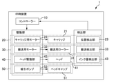
図1A及び図1Bは、印刷装置1の基本構成の概要説明図である。図1Aは、印刷装置1の外観の概略説明図である。図1Bは、印刷装置1のブロック図である。
=== First Embodiment ===
<Basic configuration of printing device 1>
1A and 1B are schematic explanatory views of a basic configuration of the printing apparatus 1. FIG. 1A is a schematic explanatory view of the appearance of the printing apparatus 1. FIG. 1B is a block diagram of the printing apparatus 1.
以下の説明では、キャリッジ21の移動方向を「走査方向」と呼ぶことがある。また、印刷時における媒体の移動方向を「搬送方向」と呼び、媒体の供給側を「上流(上流側)」と呼び、媒体の排紙側を「下流(下流側)」と呼ぶことがある。また、走査方向及び搬送方向をまとめて「水平方向」と呼ぶことがある。また、走査方向及び搬送方向に直交する方向を「垂直方向」と呼ぶことがある。また、垂直方向において、媒体の印刷面から見てキャリッジ21の側を「上(上側)」と呼び、逆側を「下(下側)」と呼ぶことがある。
In the following description, the moving direction of the
印刷装置1は、印刷媒体(例えば印刷用紙など)にインク滴を吐出して画像を印刷するための装置である。具体的には、印刷装置1は、インクジェットプリンタである。本実施形態の印刷装置1は、コントローラー10と、キャリッジ部20と、搬送部30と、印刷部40と、キャップ部50とを備えている。
The printing device 1 is a device for ejecting ink droplets onto a printing medium (for example, printing paper) to print an image. Specifically, the printing device 1 is an inkjet printer. The printing apparatus 1 of the present embodiment includes a
コントローラー10は、印刷装置1の制御を司る制御部である。コントローラー10は、外部のコンピューターからの印刷指令に基づいて、印刷装置1の駆動部(キャリッジ用モーター22、搬送用モーター32、ヘッド駆動部42、吸引ポンプ52など)を制御する。また、コントローラー10は、印刷装置1の内部の検出部(位置検出部23、搬送検出部33、インク量検出部43)の検出結果に基づくフィードバック制御を行う。
The
次いで、キャリッジ部20について説明する。キャリッジ部20は、キャリッジ21を走査方向に往復移動させるためのユニットである。キャリッジ部20は、キャリッジ21と、キャリッジ用モーター22とを有する。キャリッジ21は、走査方向に往復移動する部材である。キャリッジ21にはヘッド41が搭載されており、キャリッジ21が走査方向に往復移動することによって、ヘッド41を走査方向に往復移動させることができる。キャリッジ用モーター22は、キャリッジ21を走査方向に移動させるための駆動部である。キャリッジ部20は、キャリッジ21の走査方向の位置を検出するための位置検出部23を有する。
Next, the
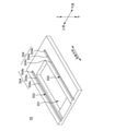
図2を用いて、キャリッジ21の構成について詳細に説明する。図2は、キャリッジ21及びヘッド41の構成を説明するための斜視図である。キャリッジ21は、可動部(不図示)と、可動部に固定されるフレーム60とを有する。不図示の可動部は、走査方向に沿って形成されたガイドレール24(図1A参照)に沿って移動する部材であり、この可動部にフレーム60が取り付けられることによってキャリッジ21が構成されている。フレーム60は、ヘッド41を可動部に取り付けるための部材である。フレーム60は、ヘッド搭載フレーム61と、固定用フレーム62とを有する。
The configuration of the
ヘッド搭載フレーム61は、ヘッド41を搭載する部材であり、走査方向及び搬送方向に平行な側面形状を有する板状の部材である。ヘッド搭載フレーム61は、媒体と対向する対向面611を有する。
The
ヘッド搭載フレーム61(対向面611)には、ヘッド用貫通穴612が形成されている。ヘッド用貫通穴612には、ヘッド41の下部が挿通されている。これにより、ヘッド41のノズル面が、ヘッド搭載フレーム61の下面(媒体と対向する対向面611)よりも下側(媒体の側)に突出して配置することが可能になる。
The head mounting frame 61 (opposing surface 611) is formed with a head through
ヘッド搭載フレーム61には、ヘッド41に関連する部品が取り付けられる。たとえば、対向面611と反対側の面に、集積回路などの電子部品や、電子部品をヘッド搭載フレーム61に固定するための機構部品などが取り付けられている。
Parts related to the
ヘッド搭載フレーム61の対向面611には、対向面611から突出する搬送側ガード部63が設けられている。本実施形態においては、対向面611の2箇所に搬送側ガード部63が設けられている。具体的には、ヘッド41に対して搬送方向の上流側に第1搬送側ガード部63Aが設けられ、下流側に第2搬送側ガード部63Bが設けられている。以下の説明において、これらを区別しない場合には両者を搬送側ガード部63と呼ぶ。なお、搬送側ガード部63は、ヘッド搭載フレーム61の対向面611にヘッド搭載フレーム61と一体で形成されている。しかし、これに限られず、搬送側ガード部63は、ヘッド搭載フレーム61と別部材であって、ヘッド搭載フレーム61に取り付けられる態様であってもよい。
The facing
搬送側ガード部63は、ジャム(紙詰まり)発生時にヘッド41を保護するための部位である。搬送側ガード部63は、走査方向に延在している。つまり、第1搬送側ガード部63A及び第2搬送側ガード部63Bは、ヘッド41に対して、搬送方向でヘッド41を囲むように配置されている。具体的には、搬送方向下流側から見たときに、搬送側ガード部63が設けられた領域が、ヘッド41の設けられた領域(走査方向におけるヘッド41の領域)と重複するように、搬送側ガード部63が形成されている。これにより、ジャム発生時に媒体が搬送方向上流または下流側、さらにはヘッド41の走査方向からヘッド41に向かって侵入することを抑制できる。つまり、搬送側ガード部63は、ジャム発生時の媒体に対するヘッド41にとっての防壁としての機能を有する。
The transport
また、ジャム発生時に媒体が搬送方向下流側からヘッド41に向かって侵入することを抑制する観点から、搬送側ガード部63の高さ(すなわちキャリッジ21の下面と媒体との距離)は、ヘッド41のノズル面がキャリッジ21の下面から媒体に向かって突出する高さと同じか、またはより高いことが望ましい。
Further, from the viewpoint of suppressing the medium from invading the
搬送側ガード部63には、印刷装置1の組み立て時にヘッド搭載フレーム61とヘッドキャップ搭載フレーム542との位置合わせを行うための、基準面631が設けられている。位置合わせは、ヘッド41のクリーニング時に、ヘッド41のノズルプレート412とヘッドキャップ51とを互いに対向させ、且つ互いに適度な押圧で当接した状態とするために行う。この位置合わせの詳細については後述する。
The transport
本実施形態においては、基準面631は、第1搬送側ガード部63Aの両端及び第2搬送側ガード部63Bの両端に設けられている。基準面631は、垂直方向基準面631aと、走査方向基準面631bと、搬送方向基準面631cとを含む。搬送側ガード部63の端部の各々における基準面631は、垂直方向基準面631a、走査方向基準面631b及び搬送方向基準面631cが互いに隣接するように設けられている。垂直方向基準面631a、走査方向基準面631b及び搬送方向基準面631cは、互いに直交するように設けられている。これにより、これら3つの基準面631は、ヘッド41の走査方向および垂直方向の動作および媒体の搬送方向の動作との向きと角度が一致することになり、ヘッド搭載フレーム61とヘッドキャップ搭載フレーム542との位置合わせを確実に行うことができる。
In the present embodiment, the
垂直方向基準面631aは、ヘッド搭載フレーム61とヘッドキャップ搭載フレーム542との垂直方向の位置合わせをするために設けられている。垂直方向基準面631aは、垂直方向に垂直な平面である。垂直方向基準面631aは、対向面611の計4か所に設けられている。垂直方向基準面631aは、搬送側ガード部63の他の面よりも下側に向かって突出している。つまり、垂直方向基準面631aは、搬送側ガード部63の他の面よりも対向面611から突出している(離れている)。また、垂直方向基準面631aの搬送方向の幅は、基準面631の部分を除く搬送側ガード部63の他の領域の幅よりも広い。
The
走査方向基準面631bは、ヘッド搭載フレーム61とヘッドキャップ搭載フレーム542との走査方向の位置合わせをするために設けられている。走査方向基準面631bは、走査方向に垂直な平面である。走査方向基準面631bは、搬送側ガード部63の走査方向の両端部に設けられている。つまり、走査方向基準面631bは、対向面611の計4か所に設けられている。
The scanning
搬送方向基準面631cは、ヘッド搭載フレーム61とヘッドキャップ搭載フレーム542との搬送方向の位置合わせをするために設けられている。搬送方向基準面631cは、搬送方向に垂直な平面である。搬送側ガード部63の端部の各々において、搬送方向基準面631cは、搬送方向の上流側及び下流側の2か所に設けられている。つまり、搬送方向基準面631cは、対向面611の計8か所に設けられている。
The transport
走査方向基準面631b及び搬送方向基準面631cを用いることによって、ヘッド搭載フレーム61とヘッドキャップ搭載フレーム542との水平方向の位置合わせをすることができる。詳細は後述するが、水平方向の位置合わせにおいて、4か所に設けられた走査方向基準面631b及び8か所に設けられた搬送方向基準面631cは、必ずしも全て使用されなくてもよい。
By using the scanning
位置合わせにおいて、特にヘッド41のノズルプレート412とヘッドキャップ51とが互いに対向し、適度な押圧で当接する状態になるよう調整することが重要であるため、基準面631は、可能な限りヘッド41に近い位置に配置されることが好ましい。つまり、本実施形態において、基準面631は搬送側ガード部63に設けられるため、搬送側ガード部63自体が可能な限りヘッド41に近い位置に配置されることが好ましい。
In the alignment, it is particularly important to adjust the
尚、本実施形態においては、ヘッド搭載フレーム61は、ダイカストによる金属部材で構成されている。そして、ダイカストによって金属部材を構成した後に、更に切削加工によって基準面631が形成される。基準面631は、前述の通り位置合わせのために設けられる。従って、基準面631可能な限り平坦であることが好ましい。切削加工によって基準面631を形成することにより、ダイカストによって形成される表面よりも平坦な面を形成することができる。また、前述したように、垂直方向基準面631aは、搬送側ガード部63の他の面よりも対向面611から突出した構成になっている。従って、垂直方向基準面631aを形成するには、突出した部分のみを切削すればよいため、加工工数を削減できる。
In this embodiment, the
固定用フレーム62は、ヘッド搭載フレーム61を可動部(不図示)に固定するための部材である。一対の固定用フレーム62が、ヘッド搭載フレーム61を走査方向から挟むように設けられている。ここでは、固定用フレーム62は、第1固定用フレーム621及び第2固定用フレーム622の2つの部材で構成されている。第1固定用フレーム621は、ヘッド搭載フレーム61を固定するL字状の部材である。なお、L字状の第1固定用フレーム621の下面は、媒体と対向する対向面となる。第2固定用フレーム622は、可動部に固定される部材であり、可動部に対して第1固定用フレーム621を固定する部材である。但し、固定用フレーム62は、1つの部材で構成されても良いし、3つ以上の部材で構成されても良い。
The fixing frame 62 is a member for fixing the
固定用フレーム62(詳しくは、第1固定用フレーム621)の下面には、走査側ガード部62Aが形成されている。走査側ガード部62Aは、ジャム発生時にヘッド41を保護するための部位である。走査側ガード部62Aは、媒体の側に向かって突出して形成された突出部であり、ヘッド41から見て走査方向の両側に配置されている。言い換えると、一対の走査側ガード部62Aが、ヘッド41を挟むように設けられている。走査側ガード部62Aは、搬送方向に沿って突出した部位である。走査方向から見たときに、走査側ガード部62Aが設けられた領域(搬送方向における走査側ガイドの領域)が、ヘッド41の設けられた領域(搬送方向におけるヘッド41の領域)と重複するように、走査側ガード部62Aが形成されている。これにより、ジャム発生時に移動中のキャリッジ21が媒体と接触して、媒体がキャリッジ21の下側に巻き込まれてしまっても、走査側ガード部62Aが防壁として機能して、ヘッド41と媒体とが接触することを抑制でき、これによりヘッド41を保護することができる。
A scanning
次いで、搬送部30について説明する。搬送部30は、媒体を搬送するためのユニットである。搬送部30の搬送する媒体は、ロール紙や単票用紙でも良いし、紙以外の媒体でも良い。搬送部30は、搬送ローラー31と、搬送用モーター32と、搬送検出部33とを有する。搬送ローラー31は、媒体を搬送するための回転ローラーである。搬送用モーター32は、搬送ローラー31を回転させるための駆動部である。搬送検出部33は、媒体の搬送量を検出するために設けられている。
Next, the
印刷部40は、媒体にインク滴を吐出するためのユニットである。印刷部40は、ヘッド41と、ヘッド駆動部42とを有する。ヘッド41は、インクを吐出するための多数のノズルを備えたインクジェット式の印刷ヘッドである。ヘッド駆動部42は、ヘッド41の各ノズルからのインク滴の吐出/非吐出を行わせる駆動部である。ヘッド駆動部42は、例えばヘッド41がピエゾ式であればピエゾ素子を駆動する駆動部である。ヘッド41は、キャリッジ21に搭載されており、キャリッジ21とともに走査方向に往復移動する。印刷部40は、ヘッド41内のインク貯留部(不図示)におけるインク貯留量を検出するためのインク量検出部43を有する(図1B参照)。
The
図2に示すように、ヘッド41は、ベース部材(不図示)と、ノズルプレート412と、プレート保持部材413とを有する。ベース部材は、ヘッド41の本体を構成する部材である。ベース部材には、供給されたインクが貯留されるインク貯留部が設けられている。ノズルプレート412は、ノズル穴(不図示)が形成された板状の部材である。ここでは、ノズルプレート412は金属板で構成されている。ノズルプレート412の下面は、ノズル穴が開口したノズル面になっており、媒体と対向する。プレート保持部材413は、ノズルプレート412を保持するための部材である。上述の通りヘッド41の下部は、ヘッド用貫通穴612に挿通されており、ヘッド41のノズル面(ノズルプレート412の下面)が、ヘッド搭載フレーム61の下面(媒体と対向する対向面611)よりも下側(媒体の側)に突出している。
As shown in FIG. 2, the
本実施形態では、プレート保持部材413は、薄い金属板で構成されている。このため、仮にジャム発生時にヘッド41が媒体と接触してしまうと、薄いプレート保持部材413が破壊されてしまい、ヘッド41が故障してしまう。したがって、本実施形態のように薄い金属板によるプレート保持部材413でノズルプレート412を保持した構成では、媒体とヘッド41との接触を抑制することが特に望ましく、ガード部(走査側ガード部62Aや搬送側ガード部63)を設けることが特に有効になる。但し、プレート保持部材413が破壊されにくい場合や、プレート保持部材413が無い場合においても、ヘッド41を保護するためにガード部を設けることは有効である。
In this embodiment, the
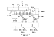
次いで、キャップ部50について説明する。図3は、キャップ部50の構成を説明する斜視図である。キャップ部50は、ヘッド41のクリーニングを行うためのユニットである。キャップ部50は、媒体が搬送される印刷領域の外側において、印刷装置1の筐体内に設けられた設置面(図示せず)上に固定されて配置される。本実施形態においては、印刷装置1の筐体内に配置されている。キャップ部50は、ヘッドキャップ51と、吸引ポンプ52(図1B参照。図3では記載を省略している)と、フレーム54とを有する。
Next, the
ヘッドキャップ51は、ヘッド41のクリーニング時に、ヘッド41のノズルプレート412に当接してヘッド41を覆う。ヘッドキャップ51がヘッド41のノズルプレート412に当接すると、ヘッドキャップ51及びヘッド41が閉空間を形成する。吸引ポンプ52は、ヘッドキャップ51がヘッド41のノズルプレート412に当接した状態において、当該閉空間の空気やインクを吸引することによって、ヘッド41に負圧を引加する。これによって、ヘッド41に付着した異物や、ノズルに詰まった異物等を吸引したりすることができる。
When cleaning the
フレーム54は、ヘッドキャップ51を支持するための部材である。また、フレーム54は、ヘッド41のクリーニングを行う際に、ヘッドキャップ51の位置を移動させて、ヘッド41のノズルプレート412に当接又は離間させるための部材である。フレーム54は、支持フレーム541、支柱543及びヘッドキャップ搭載フレーム542を有する。
The
支持フレーム541は、印刷装置1の筐体に対して固定され、ヘッドキャップ搭載フレーム542を支持する部材である。支持フレーム541は、底板541A、側板541B、天板541C、垂直方向アジャスタ541D及び水平方向アジャスタ541Gを有する。
The
底板541Aは、側板541B及び天板541Cを支持する部材であって、キャップ部50の設置面に固定される部材である。底板541Aは、水平方向アジャスタ541Gを介してキャップ部50の設置面に固定されている。
The bottom plate 541A is a member that supports the side plate 541B and the top plate 541C, and is a member that is fixed to the installation surface of the
水平方向アジャスタ541Gは、キャップ部50の設置面に対する底板541Aの水平方向の配置を適切な位置で固定するために設けられている。本実施形態において、水平方向アジャスタ541Gは、底板541Aの4か所に設けられている。つまり、底板541Aは、キャップ部50の設置面に対し4か所で固定されている。4か所の水平方向アジャスタ541Gの配置は、キャップ部50を設置面に安定して固定することができる配置であればよい。4か所の水平方向アジャスタ541Gは、例えば四角形の頂点の位置に配置されればよい。四角形は、例えば長方形である。4か所の水平方向アジャスタ541Gは、互いに離れて配置されるほどキャップ部50を設置面に安定して固定することができ、底板541Aの周辺部近傍に設けられることが好ましい。
The
本実施形態においては、水平方向アジャスタ541Gは、底板541Aに設けられた挿通口541H及びネジ541Iによって構成されている。底板541Aは、挿通口541Hを介してネジ541Iによってキャップ部50の設置面に固定される。これによって、キャップ部50の設置面に対する底板541Aを水平方向の適切な位置に固定することができる。
In the present embodiment, the
側板541Bは、底板541Aの上に、搬送方向上流側及び下流側の2か所に固定されて配置されている。これら2つの側板541Bの各々は、搬送方向に垂直な平面を構成するように配置されている。 The side plates 541B are fixedly arranged on the bottom plate 541A at two locations, one on the upstream side and the other on the downstream side in the transport direction. Each of these two side plates 541B is arranged so as to form a plane perpendicular to the transport direction.
天板541Cは、底板541Aの上方かつ2つの側板541Bに挟持されている。天板541Cは、垂直方向アジャスタ541Dを介して2つの側板541Bに固定されている。垂直方向アジャスタ541Dは、底板541Aに対する天板541Cの高さ及び角度を微調整できるように設けられている。垂直方向アジャスタ541Dは、2つの側板541Bの各々の2か所に設けられている。つまり、天板541Cは、2つの側板541Bに対し4か所で固定されている。垂直方向アジャスタ541Dは、これらの4か所の各々において、側板541Bに対して天板541Cが固定される位置の高さを微調整することにより、底板541Aに対する天板541Cの高さ及び角度を微調整することができる。
The top plate 541C is sandwiched above the bottom plate 541A and between two side plates 541B. The top plate 541C is fixed to the two side plates 541B via the
また、垂直方向アジャスタ541Dは、側板541Bに設けられた挿通口541E及びネジ541Fによって構成されている。挿通口541Eは、垂直方向(上下方向)に延在している。側板541B及び天板541Cは、挿通口541Eを介してネジ541Fによって固定される。挿通口541Eは垂直方向に延在しているため、ネジ541Fで固定する位置は側板541Bに対して垂直方向に微調整することができる。これによって、底板541Aに対する天板541Cの高さ及び角度を微調整することができる。
Further, the
支柱543は、天板541Cの4か所に固定されて配置されている。これらの支柱543は、走査方向及び搬送方向に2行2列で配列されている。天板541Cの4か所に配置された支柱543の各々には、同じレイアウトのカム溝543Aが設けられている。カム溝543Aのレイアウトは、搬送方向から見た場合に、概ね階段状になっている。
The
ヘッドキャップ搭載フレーム542は、ヘッドキャップ51を搭載する部材である。ヘッドキャップ51は、ヘッドキャップ搭載フレーム542に対して所定の間隔で固定されている。ヘッドキャップ搭載フレーム542は、ヘッド41のクリーニングの際及び位置合わせの際にキャリッジ21と対向する対向面542Aを有する。対向面542Aは、位置合わせにおいて、キャップ部50側の基準面の一つとしての機能を有する。ヘッドキャップ搭載フレーム542は、更に、対向面542Aの走査方向端部近傍に、上方向に突出したレバー542Bを有する。キャリッジ21がレバー542Bを押すことによって、ヘッドキャップ搭載フレーム542を走査方向に移動させることができる。
The head
本実施形態においては、ヘッドキャップ搭載フレーム542は、搬送方向に平行な2辺及び走査方向に平行な2辺を有する概ね矩形の形状を有している。ヘッドキャップ搭載フレーム542は、支柱543に搬送方向から挟まれるように配置されている。ヘッドキャップ搭載フレーム542は、走査方向に平行な2辺にそれぞれ2つのスライドピン542Cを有し、これらのスライドピン542Cが支柱543のカム溝543Aそれぞれに係合することによって、支持フレーム541に支持されている。また、ヘッドキャップ搭載フレーム542は、スライドピン542Cがカム溝543Aに沿って走査方向に移動することに伴って垂直方向に移動することができる。
In the present embodiment, the head
コイルばね544は、支持フレーム541及びヘッドキャップ搭載フレーム542を接続する。これによって、ヘッドキャップ搭載フレーム542は、コイルばね544によって走査方向の一方側に力を受け、スライドピン542Cの移動がカム溝543A端部の内、垂直方向の高さが低い側の端部で規制される。これによって、ヘッドキャップ搭載フレーム542は、通常時は、支持フレーム541に対して垂直方向の高さが最も低い位置で静止している。
The
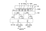
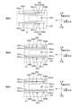
<ヘッドとヘッドキャップとの位置合わせの方法>
次いで、ヘッド41とヘッドキャップ51との位置合わせの方法について説明する。図5A乃至図5Dは、本実施形態に係るヘッド41とヘッドキャップ51との位置合わせの方法を説明するための、搬送方向下流側から見た模式図である。図6A乃至図6Cは、本実施形態に係るヘッド41とヘッドキャップ51との位置合わせの方法を説明するための、垂直方向から見た模式図である。図6A乃至図6Cにおいては、位置合わせ用治具55(図4)及び搬送側ガード部63のみに着目し、これらを実線で示している。この位置合わせは、ヘッド41を基準として、ヘッドキャップ51の相対位置を垂直方向及び水平方向(走査方向と搬送方向)のそれぞれについて調整を行うことにより実現する。尚、以下に説明する方法においては、特にヘッド搭載フレーム61とヘッドキャップ搭載フレーム542との位置合わせを行うことによって、それぞれに固定されたヘッド41とヘッドキャップ51との位置合わせを実現する。また、この位置合わせは、印刷装置1を組み立てる際に行う。
<Method of aligning the head and head cap>
Next, a method of aligning the
ヘッド41のクリーニングを行う際に、ヘッドキャップ51をヘッド41のノズルプレート412に当接させたときに、ヘッドキャップ51及びヘッド41が閉空間を形成しなければならない。ヘッドキャップ51及びヘッド41のノズルプレート412の間に隙間等が存在して閉空間が形成されないと、吸引ポンプ52によってノズルに適切な負圧を引加することができない。つまり、ヘッド41のクリーニングを正しく行うことができない。例えば水平方向において、キャリッジ21の対向面611及びヘッドキャップ搭載フレーム542の対向面542Aが互いに平行でなかったり、垂直方向において、ヘッド41に対してヘッドキャップ51の位置が離れすぎていたりすると、当該閉空間を形成することができない場合がある。このような問題がヘッド41のクリーニング時に発生しないように、印刷装置1の組み立ての際に、高い精度でヘッド41に対してヘッドキャップ51の水平方向及び垂直方向の位置合わせをしておくことが必要になる。
When cleaning the
以下では、ヘッド搭載フレーム61を基準として、ヘッドキャップ搭載フレーム542の相対位置を水平方向及び垂直方向のそれぞれについて調整することによって、両者の位置合わせを行う方法について説明する。
Hereinafter, a method of aligning the head
図5A及び図6Aは、キャリッジ21が走査方向のキャップ部50へ向かって移動しているときの模式図である。この時点において、ヘッドキャップ搭載フレーム542は、移動可能な垂直方向の範囲で、最も下に位置する状態にある。つまり、この時点において、ヘッド41及びヘッドキャップ搭載フレーム542の垂直方向の高さの差が最も大きい。
5A and 6A are schematic views when the
また、位置合わせを行うにあたって、ヘッドキャップ搭載フレーム542の対向面542Aに、位置合わせ用治具55を配置する。図4は、本実施形態に係る位置合わせ用治具55の構成を説明する斜視図である。位置合わせ用治具55は、ヘッドキャップ搭載フレーム542に脱着可能な板状の部材である。位置合わせ用治具55は、開口部551及び溝部552を有している。
Further, in performing the alignment, the
位置合わせ用治具55がヘッドキャップ搭載フレーム542に配置された状態において、位置合わせ用治具55の長手方向は走査方向に対応し、位置合わせ用治具55の短手方向は搬送方向に対応し、位置合わせ用治具55の高さ方向は上下方向に対応する。
When the
位置合わせ用治具55には、開口部551及び溝部552が設けられている。開口部551は、位置合わせ用治具55の略中央部に設けられ、位置合わせ用治具55を貫通している。本実施形態においては、開口部551は矩形の形状を有している。
The
溝部552は、位置合わせ用治具55の2か所に設けられ、それぞれ走査方向に延在している。2か所の溝部552は、搬送方向の上流側及び下流側から開口部551を挟むように配置されている。2か所の溝部552の各々の一端は、位置合わせ用治具55の一側面に達している。また、2か所の溝部の各々の他端は、位置合わせ用治具55の当該一側面に対向する側面に達していない。溝部がこのような形状を有することによって、位置合わせ用治具55の当該一側面にのみ、溝部552の断面形状が現れている。
The
溝部552は、その側面に当接面554を有する。当接面554は、位置合わせの際の、キャップ部50側の基準面として機能する。当接面554は、垂直方向当接面554aと、走査方向当接面554bと、搬送方向当接面554cとを含む。
The
垂直方向当接面554aは、位置合わせの際の、キャップ部50側の垂直方向の基準面として機能する。垂直方向当接面554aは、溝部552の底面である。垂直方向当接面554aは、位置合わせ用治具55がヘッドキャップ搭載フレーム542に配置された状態において、垂直方向に垂直な平面である。
The
走査方向当接面554bは、位置合わせの際の、キャップ部50側の走査方向の基準面として機能する。走査方向当接面554bは、溝部552の走査方向の両端の内、一端側のみに設けられている。位置合わせ用治具55がヘッドキャップ搭載フレーム542に配置された状態において、走査方向当接面554bは、走査方向に垂直な平面である。
The scanning
搬送方向当接面554cは、位置合わせの際の、キャップ部50側の搬送方向の基準面として機能する。搬送方向当接面554cは、位置合わせ用治具55がヘッドキャップ搭載フレーム542に配置された状態において、搬送方向に垂直な平面である。搬送方向当接面554cは、1つの溝部において、搬送方向上流側及び下流側の2か所に設けられている。
The transport
図5Aにおいて、キャリッジ21が走査方向右側(印刷領域に対して、ヘッド41の待機位置が設けられる側)へ移動した場合、キャリッジ21に設けられている搬送側ガード部63は、それぞれ対応する溝部552に沿って移動する。キャリッジ21が更に走査方向右側へ移動すると、搬送側ガード部63の走査方向基準面631bは、位置合わせ用治具55の走査方向当接面554bに接触する(図5B及び図6B参照)。これにより、キャリッジ21を基準として、キャップ部50の走査方向の位置が定められる。より詳しくは、ヘッド搭載フレーム61の位置を基準にして、ヘッドキャップ搭載フレーム542の走査方向の位置を、ヘッド搭載フレーム61に対して合わせる。
In FIG. 5A, when the
図5B及び図6Bの状態から、キャリッジ21が更に右側へ移動すると、ヘッドキャップ搭載フレーム542は、キャリッジと21の走査方向の相対位置を保ったまま、キャリッジ21の進行方向へ移動すると共にスライドピン542Cがカム溝543Aに沿って移動することによって、上方向に移動する。
When the
図5B及び図6Bにおいて、キャリッジ21が移動可能な走査方向の範囲で、最も右へ移動すると、ヘッドキャップ搭載フレーム542は、移動可能な垂直方向の範囲で、最も上に位置する状態になる(図5C)。
In FIGS. 5B and 6B, when the
この状態において、ヘッド41とヘッドキャップ51との水平方向における位置合わせを行う。より詳しくは、ヘッド搭載フレーム61の位置を基準にして、ヘッドキャップ搭載フレーム542の水平方向の位置を、ヘッド搭載フレーム61に対して合わせる。
In this state, the
先ず、ヘッドキャップ搭載フレーム542とヘッド搭載フレーム61との搬送方向における位置合わせを行う。搬送側ガード部63に設けられた搬送方向基準面631cと、位置合わせ用治具55の搬送方向当接面554cが互いに接触するように、ヘッドキャップ搭載フレーム542の搬送方向の位置を決定する(図6C)。本実施形態においては、搬送方向の上流側の搬送方向基準面631cと、搬送方向の上流側の搬送方向当接面554cが互いに接触するように位置合わせをしている。ヘッドキャップ搭載フレーム542の搬送方向の位置を決定したら、水平方向アジャスタ541Gで固定する。このように、走査方向と搬送方向それぞれの位置合わせを行うことで、キャリッジ21とヘッドキャップ51との水平方向の位置合わせが完了する。この場合、ヘッド41のノズルプレート412及びヘッドキャップ51が互いに対向した状態にすることができる。
First, the head
尚、水平方向の位置合わせにおいては、基準面631が高精度の平面を有すると考えると、理論上は、キャリッジ21側の1か所の走査方向基準面631b及び1か所の搬送方向基準面631cが定まればよい。しかし、走査方向基準面631bおよび搬送方向基準面631cの面積は、キャップユニットに対して相対的に小さく、キャリッジ側の1か所の走査方向基準面631b及び1か所の搬送方向基準面631cのみで水平方向の位置合わせを行うことは実際には困難である。よって、キャリッジ21側及びキャップ部50側に設けられた基準面の内、少なくとも3か所を使って水平方向の位置合わせを行う。例えばキャリッジ側の2か所の走査方向基準面631b及び少なくとも1か所の搬送方向基準面631cが、位置合わせ用治具55の対応する当接面554に接触するように位置合わせを行えばよい。
Considering that the
次にヘッドキャップ搭載フレーム542とヘッド搭載フレーム61との垂直方向における位置合わせを行う。先ず、ヘッド搭載フレーム61に設けられた垂直方向基準面631a(本実施形態においては4か所に設けられている)と、位置合わせ用治具55の垂直方向当接面554aとが互いに接触するように、ヘッドキャップ搭載フレーム542の高さ及び角度を微調整する。この微調整は、支持フレーム541に設けられた垂直方向アジャスタ541Dを用いて調整すればよい。これによって、ヘッドキャップ搭載フレーム542とヘッド搭載フレーム61との垂直方向の位置合わせを行うことができ、ヘッド41のノズルプレート412及びヘッドキャップ51が互いに適度な押圧で当接した状態にすることができる。
Next, the head
この状態において、レバー542Bをキャリッジ21に対して押し当て、ヘッドキャップ搭載フレーム542に対して螺子などの固定手段で固定する(図5D参照)。これにより、位置合わせ用治具55が取り外されても、キャリッジ21がレバー542Bに接触した状態でキャリッジ21及びヘッドキャップ51が共に移動する範囲では、ヘッド搭載フレーム61に対するヘッドキャップ搭載フレーム542の走査方向における位置は適切に維持される。以上の方法により、ヘッド搭載フレーム61とヘッドキャップ搭載フレーム542との位置合わせが完了すると、それぞれに固定されたヘッド41とヘッドキャップ51との位置合わせが実現する。
In this state, the
位置合わせが完了した後、キャリッジ21を左側へ移動させてキャリッジ21とヘッドキャップ51とを離間させ、位置合わせ用治具55をヘッドキャップ搭載フレーム542から取り外す。その後のクリーニング時にも、ヘッド41及びヘッドキャップ51を同じ状態に保つことができる。
After the alignment is completed, the
<ヘッドのクリーニング>
次いで、ヘッド41のクリーニングについて説明する。図7は、ヘッド41のクリーニングを説明するための模式図である。ヘッド41のクリーニングは、図7のような状態で行う。この状態は、ヘッド41のノズルプレート412及びヘッドキャップ51を互いに当接させている(なお、クリーニング時には位置合わせ用治具55は使用しない)。本実施形態に係る印刷装置1は、前述の位置合わせが完了した状態となっているため、クリーニング時にはヘッド41のノズルプレート412及びヘッドキャップ51を互いに適度な押圧で当接することができる。この状態において、吸引ポンプ52が、ヘッドキャップ51及びヘッド41が形成する閉空間の空気またはインクを吸引することによって、ヘッド41に付着した異物や、ノズルに詰まった異物等が吸引される。
<Head cleaning>
Next, cleaning of the
以上説明した本実施形態に係る印刷装置1は、媒体を搬送方向に搬送する搬送部30と、インクを吐出するヘッド41と、ヘッド41を搭載し、走査方向に移動可能なキャリッジ21と、ヘッド41に対向してヘッド41のクリーニングを行うヘッドキャップ51と、を備え、キャリッジ21は、媒体と対向する対向面611を有し、対向面611には、媒体に向かって突出する搬送側ガード部63が設けられ、搬送側ガード部63には、ヘッド搭載フレーム61とヘッドキャップ搭載フレーム542との位置合わせをするための基準面631が設けられている。
The printing apparatus 1 according to the present embodiment described above includes a
つまり、対向面611内に、搬送側ガード部63及び基準面631を配置するためのスペースを別々に設ける必要がなく、ガード部を配置するためのスペースに基準面631を配置することができる。これによって、キャリッジ21の下面を省スペース化し、かつ部品点数を抑えることができる。
That is, it is not necessary to separately provide a space for arranging the transport
本実施形態において、基準面631は、ヘッド搭載フレーム61とヘッドキャップ搭載フレーム542との垂直方向の位置合わせをするための垂直方向基準面631aと、ヘッド搭載フレーム61とヘッドキャップ搭載フレーム542との走査方向の位置合わせをするための走査方向基準面631bと、ヘッド搭載フレーム61とヘッドキャップ搭載フレーム542との搬送方向の位置合わせをするための搬送方向基準面631cとを含む。これによって、ヘッド搭載フレーム61に対してヘッドキャップ搭載フレーム542の垂直方向、走査方向及び搬送方向の位置合わせをすることができる。
In the present embodiment, the
本実施形態において、垂直方向基準面631a、走査方向基準面631b、搬送方向基準面631cは互いに直交する。これにより、ヘッド搭載フレーム61に対してヘッドキャップ搭載フレーム542の垂直方向、走査方向及び搬送方向の位置合わせを確実にすることができる。
In the present embodiment, the
本実施形態において、搬送側ガード部63は、走査方向に延在しており、ヘッド41に対して、搬送方向でヘッド41を囲み、垂直方向基準面631aは、搬送側ガード部63の両端部に設けられている。これによって、ジャム発生時に媒体が搬送方向上流または下流側、さらにはヘッド41の走査方向からヘッド41に向かって侵入することを抑制することができる。
In the present embodiment, the transport
本実施形態において、基準面631は、搬送側ガード部63の他の面よりも媒体に向かって突出している。これによって、搬送側ガード部63の機械的強度が向上する。
In the present embodiment, the
本実施形態において、基準面631は、切削加工により形成されている。これによって、ヘッド搭載フレーム61とヘッドキャップ搭載フレーム542との位置合わせのために必要な、垂直方向基準面631aの平坦性を確保することができる。
In the present embodiment, the
本実施形態において、基準面631の搬送方向の幅は、ガード部の他の領域の幅よりも広い。これによって、ガード部の機械的強度が向上する。
In the present embodiment, the width of the
本実施形態において、搬送側ガード部63は、対向面611に一体で形成されている。これによって、搬送側ガード部63のための部材を別途設ける必要がなく、部品点数を抑えてキャリッジ21の構造を単純化することができる。
In the present embodiment, the transport
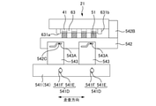
===第2実施形態===
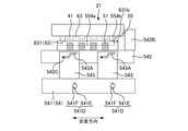
本実施形態に係る印刷装置について説明する。図8は、キャリッジ21及びヘッド41を斜め下から見た斜視図である。
=== Second embodiment ===
The printing apparatus according to this embodiment will be described. FIG. 8 is a perspective view of the
本実施形態に係る印刷装置は、第1実施形態に係る印刷装置1と比べると、第2搬送側ガード部63Bの垂直方向基準面631aとは独立に、垂直方向基準面631aが2か所に設けられている。これらの2か所の垂直方向基準面631aは、ヘッド搭載フレーム61の対向面611と一体で形成されている。これらの2か所の垂直方向基準面631aは、第1搬送側ガード部63Aに設けられた基準面の垂直方向基準面631aよりも、対向面611からの高さが低い。このように、ガード部とは独立に、ヘッド搭載フレーム61の対向面611と一体で形成された垂直方向基準面631aを設けてもよい。また、複数か所に設けられた垂直方向基準面631aの対向面611からの高さは全て一定でなくてもよい。このため、本実施形態において用いられる位置合わせ用治具55は、ヘッド搭載フレーム61の対向面611からの高さが異なる垂直方向基準面631aに応じた垂直方向当接面554aを有する(図示せず)。
Compared with the printing apparatus 1 according to the first embodiment, the printing apparatus according to the present embodiment has two
更に、本実施形態に係る印刷装置は、第1実施形態に係る印刷装置1と比べると、ヘッド搭載フレーム61の構成が異なっている。具体的には、第1実施形態に係る印刷装置1は、第2搬送側ガード部63Bがヘッド搭載フレーム61の対向面611に一体で形成されているのに対し、本実施形態においては、ヘッド搭載フレーム61とは別部材を用いて形成されている。このように、複数のガード部を設ける際に、そのうちの一部がヘッド搭載フレーム61の対向面611と一体で形成されてもよい。
Further, the printing apparatus according to the present embodiment has a different configuration of the
この場合、ヘッド搭載フレーム61の対向面611に一体で形成されている第1搬送側ガード部63Aの走査方向基準面631bと搬送方向基準面631cの内、少なくとも3か所を使って、ヘッドキャップ搭載フレーム542の水平方向の位置をヘッド搭載フレーム61に対して合わせるとよい。例えばキャリッジ21側の2か所の走査方向基準面631b及び少なくとも1か所の搬送方向基準面631cが、位置合わせ用治具55の対応する当接面554に接触するように位置合わせを行えばよい。次に、第1実施形態と同様にして、ヘッドキャップ搭載フレーム542とヘッド搭載フレーム61との垂直方向における位置を合わせればよい。ヘッド搭載フレーム61に設けられた垂直方向基準面631a(本実施形態においても4か所に設けられている)と、位置合わせ用治具の垂直方向当接面とが互いに接触するように、ヘッドキャップ搭載フレーム542の高さ及び角度を微調整する。
In this case, the head cap is used at least three of the scanning
また、これとは別に、ヘッド搭載フレーム61の位置を基準にして、ヘッドキャップ搭載フレーム542の位置を、ヘッド搭載フレーム61に対して合わせる場合には、位置合わせ用のピン(図示せず)を位置合わせ用治具55側に設け、ヘッド搭載フレーム61上の対応する位置に、位置合わせ用のピンが嵌合するように、接合ピン穴(図示せず)を設けて、接合ピン穴に位置合わせ用のピンを挿入することで、ヘッドキャップ搭載フレーム542の位置を、ヘッド搭載フレーム61に対して合わせてもよい。
Separately from this, when the position of the head
===その他の実施形態===
上記実施形態は、例として提示したものであり、発明の範囲を限定するものではない。上記の構成は、適宜組み合わせて実施することが可能であり、発明の要旨を逸脱しない範囲で、種々の省略、置き換え、変更を行うことができる。上記実施形態やその変形は、発明の範囲や要旨に含まれると同様に、特許請求の範囲に記載された発明とその均等の範囲に含まれる。
=== Other embodiments ===
The above embodiment is presented as an example and does not limit the scope of the invention. The above configurations can be implemented in combination as appropriate, and various omissions, replacements, and changes can be made without departing from the gist of the invention. The above-described embodiments and variations thereof are included in the scope of the invention described in the claims and the equivalent scope thereof, as are included in the scope and gist of the invention.
1 印刷装置、10 コントローラー、
20 キャリッジ部、21 キャリッジ、
22 キャリッジ用モーター、23 位置検出部、24 ガイドレール、
30 搬送部、31 搬送ローラー、32 搬送用モーター、33 搬送検出部、
40 印刷部、41 ヘッド、412 ノズルプレート、413 プレート保持部材、
50 キャップ部、51 ヘッドキャップ、54 フレーム、541 支持フレーム、541A 底板、541B 側板、541C 天板、541D 垂直方向アジャスタ、541E 挿通口、541F ネジ、541G 水平方向アジャスタ、541H 挿通口、541I ネジ、542 ヘッドキャップ搭載フレーム、542A 対向面、542B レバー、542C スライドピン、543 支柱、543A カム溝、55 位置合わせ用治具、551 開口部、552 溝部、554 当接面、554a 垂直方向当接面、554b 走査方向当接面、554c 搬送方向当接面、
60 フレーム、61 ヘッド搭載フレーム、611 対向面、612 ヘッド用貫通穴、62 固定用フレーム、621 第1固定用フレーム、622 第2固定用フレーム、62A 走査側ガード部、63 搬送側ガード部、631 基準面、631a 垂直方向基準面、631b 走査方向基準面、631c 搬送方向基準面、63A 第1搬送側ガード部、63B 第2搬送側ガード部、
1 printing device, 10 controller,
20 carriage section, 21 carriage,
22 Carriage motor, 23 Position detector, 24 Guide rail,
30 transport unit, 31 transport roller, 32 transport motor, 33 transport detector,
40 printing unit, 41 head, 412 nozzle plate, 413 plate holding member,
50 Cap, 51 Head Cap, 54 Frame, 541 Support Frame, 541A Bottom Plate, 541B Side Plate, 541C Top Plate, 541D Vertical Adjuster, 541E Insert, 541F Screw, 541G Horizontal Adjuster, 541H Insert, 541I Screw, 542 Head cap mounting frame, 542A facing surface, 542B lever, 542C slide pin, 543 support, 543A cam groove, 55 alignment jig, 551 opening, 552 groove, 554 contact surface, 554a vertical contact surface, 554b Scanning direction contact surface, 554c transport direction contact surface,
60 frame, 61 head mounting frame, 611 facing surface, 612 head through hole, 62 fixing frame, 621 first fixing frame, 622 second fixing frame, 62A scanning side guard part, 63 transport side guard part, 631 Reference plane, 631a vertical reference plane, 631b scanning direction reference plane, 631c transport direction reference plane, 63A first transport side guard section, 63B second transport side guard section,
Claims (5)
インクを吐出するヘッドと、
前記ヘッドを搭載し、走査方向に移動可能なキャリッジと、
前記ヘッドに対向して前記ヘッドのクリーニングを行うヘッドキャップと、
を備え、
前記キャリッジは、前記媒体と対向する対向面を有し、
前記対向面には、
前記対向面から突出するガード部が設けられ、
前記ガード部には、
前記対向面と前記ヘッドキャップとの位置合わせをするための基準面が設けられ、
前記基準面は、
前記対向面と前記ヘッドキャップとの垂直方向の位置合わせをするための垂直方向基準面と、
前記対向面と前記ヘッドキャップとの走査方向の位置合わせをするための走査方向基準面と、
前記対向面と前記ヘッドキャップとの搬送方向の位置合わせをするための搬送方向基準面とを含み、
前記ガード部は、走査方向に延在しており、前記ヘッドに対して、搬送方向で前記ヘッドを囲み、
前記基準面は、前記ガード部の両端部に設けられていることを特徴とする印刷装置。 A transport unit that transports the medium in the transport direction,
The head that ejects ink and
A carriage equipped with the head and movable in the scanning direction,
A head cap that faces the head and cleans the head,
Equipped with
The carriage has a facing surface facing the medium and has a facing surface.
On the facing surface,
A guard portion protruding from the facing surface is provided, and the guard portion is provided.
The guard portion has
A reference surface for aligning the facing surface and the head cap is provided.
The reference plane is
A vertical reference surface for vertically aligning the facing surface and the head cap, and
A scanning direction reference surface for aligning the facing surface and the head cap in the scanning direction,
Includes a transport direction reference surface for aligning the facing surface and the head cap in the transport direction.
The guard portion extends in the scanning direction and surrounds the head in the transport direction with respect to the head.
A printing apparatus characterized in that the reference surface is provided at both ends of the guard portion .
The printing apparatus according to claim 1, wherein the guard portion is integrally formed on the facing surface.
Priority Applications (2)
| Application Number | Priority Date | Filing Date | Title |
|---|---|---|---|
| JP2017173969A JP6991804B2 (en) | 2017-09-11 | 2017-09-11 | Printing equipment |
| US16/125,806 US10639896B2 (en) | 2017-09-11 | 2018-09-10 | Printing apparatus |
Applications Claiming Priority (1)
| Application Number | Priority Date | Filing Date | Title |
|---|---|---|---|
| JP2017173969A JP6991804B2 (en) | 2017-09-11 | 2017-09-11 | Printing equipment |
Publications (2)
| Publication Number | Publication Date |
|---|---|
| JP2019048420A JP2019048420A (en) | 2019-03-28 |
| JP6991804B2 true JP6991804B2 (en) | 2022-01-13 |
Family
ID=65630402
Family Applications (1)
| Application Number | Title | Priority Date | Filing Date |
|---|---|---|---|
| JP2017173969A Active JP6991804B2 (en) | 2017-09-11 | 2017-09-11 | Printing equipment |
Country Status (2)
| Country | Link |
|---|---|
| US (1) | US10639896B2 (en) |
| JP (1) | JP6991804B2 (en) |
Families Citing this family (3)
| Publication number | Priority date | Publication date | Assignee | Title |
|---|---|---|---|---|
| JP7180331B2 (en) | 2018-12-03 | 2022-11-30 | カシオ計算機株式会社 | printer |
| JP7613200B2 (en) * | 2021-03-26 | 2025-01-15 | ブラザー工業株式会社 | Image Recording Device |
| JP7733872B2 (en) * | 2021-10-29 | 2025-09-04 | 株式会社リコー | Nozzle surface recovery device, droplet ejection head, and inkjet printer |
Citations (7)
| Publication number | Priority date | Publication date | Assignee | Title |
|---|---|---|---|---|
| JP2001026113A (en) | 1999-07-13 | 2001-01-30 | Seiko Epson Corp | Ink jet recording device |
| US20100053259A1 (en) | 2008-08-28 | 2010-03-04 | Hewlett-Packard Development Company Lp | Movable web support and cap |
| JP2011240550A (en) | 2010-05-17 | 2011-12-01 | Canon Inc | Recording apparatus |
| JP2012061719A (en) | 2010-09-16 | 2012-03-29 | Ricoh Co Ltd | Image forming apparatus, and method of manufacturing the same |
| JP2015163436A (en) | 2014-02-28 | 2015-09-10 | セイコーエプソン株式会社 | Liquid ejector |
| JP2016013683A (en) | 2014-06-11 | 2016-01-28 | 株式会社Okiデータ・インフォテック | Ink jet head and ink jet printer |
| JP2016538157A (en) | 2013-11-15 | 2016-12-08 | メムジェット テクノロジー リミテッド | Modular printer with narrow printing area |
Family Cites Families (6)
| Publication number | Priority date | Publication date | Assignee | Title |
|---|---|---|---|---|
| JP2746632B2 (en) * | 1989-02-03 | 1998-05-06 | キヤノン株式会社 | Liquid jet recording device |
| JPH03234633A (en) * | 1990-02-13 | 1991-10-18 | Canon Inc | Recording device |
| JP3021149B2 (en) * | 1991-12-19 | 2000-03-15 | キヤノン株式会社 | Ink jet recording means |
| US6481826B1 (en) * | 1999-09-07 | 2002-11-19 | Seiko Epson Corporation | Ink jet recording apparatus, method of discharging ink from capping unit incorporated in the apparatus, and ink composition used with the apparatus |
| US6280018B1 (en) * | 2000-05-12 | 2001-08-28 | Hewlett-Packard Company | Automatic ink-jet pen loading/unloading |
| JP2002326366A (en) | 2001-04-27 | 2002-11-12 | Canon Inc | Ink jet recording device and recording head cap |
-
2017
- 2017-09-11 JP JP2017173969A patent/JP6991804B2/en active Active
-
2018
- 2018-09-10 US US16/125,806 patent/US10639896B2/en active Active
Patent Citations (7)
| Publication number | Priority date | Publication date | Assignee | Title |
|---|---|---|---|---|
| JP2001026113A (en) | 1999-07-13 | 2001-01-30 | Seiko Epson Corp | Ink jet recording device |
| US20100053259A1 (en) | 2008-08-28 | 2010-03-04 | Hewlett-Packard Development Company Lp | Movable web support and cap |
| JP2011240550A (en) | 2010-05-17 | 2011-12-01 | Canon Inc | Recording apparatus |
| JP2012061719A (en) | 2010-09-16 | 2012-03-29 | Ricoh Co Ltd | Image forming apparatus, and method of manufacturing the same |
| JP2016538157A (en) | 2013-11-15 | 2016-12-08 | メムジェット テクノロジー リミテッド | Modular printer with narrow printing area |
| JP2015163436A (en) | 2014-02-28 | 2015-09-10 | セイコーエプソン株式会社 | Liquid ejector |
| JP2016013683A (en) | 2014-06-11 | 2016-01-28 | 株式会社Okiデータ・インフォテック | Ink jet head and ink jet printer |
Also Published As
| Publication number | Publication date |
|---|---|
| US20190077157A1 (en) | 2019-03-14 |
| US10639896B2 (en) | 2020-05-05 |
| JP2019048420A (en) | 2019-03-28 |
Similar Documents
| Publication | Publication Date | Title |
|---|---|---|
| JP6991804B2 (en) | Printing equipment | |
| US10059107B2 (en) | Liquid ejecting head, liquid ejecting apparatus, and manufacturing method of liquid ejecting head | |
| JP2013052526A (en) | Printer, and inclination adjusting mechanism for print head of the same | |
| US8205964B2 (en) | Head array unit, image forming apparatus including same, and method for manufacturing the head array unit | |
| CN112046155B (en) | Liquid ejecting head and liquid ejecting recording apparatus | |
| US20240278572A1 (en) | Liquid ejecting apparatus | |
| JP4598561B2 (en) | Head support structure, recording apparatus, and manufacturing method thereof | |
| JP2011037235A (en) | Image forming apparatus, liquid discharging head unit, and method for assembling liquid discharging device | |
| CN115071288B (en) | Positioning mechanism and positioning method of nozzle unit and image forming device | |
| USRE48390E1 (en) | Liquid jetting apparatus | |
| JP5498829B2 (en) | Inkjet printer | |
| JP2010069627A (en) | Liquid jet head positioning method and liquid jet head module | |
| JP5181797B2 (en) | Image forming apparatus | |
| JP4390941B2 (en) | Inkjet image forming apparatus | |
| JP4729957B2 (en) | Droplet discharge head bar, droplet discharge apparatus, and droplet discharge head bar manufacturing method | |
| EP1674267A2 (en) | Maintenance unit and ink jet printer | |
| JP7417939B2 (en) | Stage equipment and printing equipment | |
| JP4701765B2 (en) | Droplet discharge head bar, droplet discharge apparatus, and droplet discharge head bar manufacturing method | |
| US20110316930A1 (en) | Modular micro-fluid ejection device | |
| JP2011025479A (en) | Inkjet printer, and method for assembling head unit in the same | |
| JP2013028043A (en) | Inkjet recording apparatus | |
| JP6010934B2 (en) | Head changing jig and head changing method | |
| JP2010069628A (en) | Liquid jet head mounting method | |
| JP2010058359A (en) | Method of manufacturing liquid jet head | |
| JP7770856B2 (en) | Recording device |
Legal Events
| Date | Code | Title | Description |
|---|---|---|---|
| A621 | Written request for application examination |
Free format text: JAPANESE INTERMEDIATE CODE: A621 Effective date: 20200819 |
|
| A977 | Report on retrieval |
Free format text: JAPANESE INTERMEDIATE CODE: A971007 Effective date: 20210616 |
|
| A131 | Notification of reasons for refusal |
Free format text: JAPANESE INTERMEDIATE CODE: A131 Effective date: 20210629 |
|
| A521 | Request for written amendment filed |
Free format text: JAPANESE INTERMEDIATE CODE: A523 Effective date: 20210727 |
|
| A131 | Notification of reasons for refusal |
Free format text: JAPANESE INTERMEDIATE CODE: A131 Effective date: 20211019 |
|
| A521 | Request for written amendment filed |
Free format text: JAPANESE INTERMEDIATE CODE: A523 Effective date: 20211125 |
|
| TRDD | Decision of grant or rejection written | ||
| A01 | Written decision to grant a patent or to grant a registration (utility model) |
Free format text: JAPANESE INTERMEDIATE CODE: A01 Effective date: 20211207 |
|
| A61 | First payment of annual fees (during grant procedure) |
Free format text: JAPANESE INTERMEDIATE CODE: A61 Effective date: 20211208 |
|
| R150 | Certificate of patent or registration of utility model |
Ref document number: 6991804 Country of ref document: JP Free format text: JAPANESE INTERMEDIATE CODE: R150 |
|
| R250 | Receipt of annual fees |
Free format text: JAPANESE INTERMEDIATE CODE: R250 |
|
| S111 | Request for change of ownership or part of ownership |
Free format text: JAPANESE INTERMEDIATE CODE: R313111 |
|
| R360 | Written notification for declining of transfer of rights |
Free format text: JAPANESE INTERMEDIATE CODE: R360 |
|
| R360 | Written notification for declining of transfer of rights |
Free format text: JAPANESE INTERMEDIATE CODE: R360 |
|
| R371 | Transfer withdrawn |
Free format text: JAPANESE INTERMEDIATE CODE: R371 |
|
| S111 | Request for change of ownership or part of ownership |
Free format text: JAPANESE INTERMEDIATE CODE: R313111 |
|
| R350 | Written notification of registration of transfer |
Free format text: JAPANESE INTERMEDIATE CODE: R350 |
|
| R250 | Receipt of annual fees |
Free format text: JAPANESE INTERMEDIATE CODE: R250 |