JP6361137B2 - Single axis actuator - Google Patents
Single axis actuator Download PDFInfo
- Publication number
- JP6361137B2 JP6361137B2 JP2013273044A JP2013273044A JP6361137B2 JP 6361137 B2 JP6361137 B2 JP 6361137B2 JP 2013273044 A JP2013273044 A JP 2013273044A JP 2013273044 A JP2013273044 A JP 2013273044A JP 6361137 B2 JP6361137 B2 JP 6361137B2
- Authority
- JP
- Japan
- Prior art keywords
- pulley
- motor
- housing
- rotation transmission
- transmission shaft
- Prior art date
- Legal status (The legal status is an assumption and is not a legal conclusion. Google has not performed a legal analysis and makes no representation as to the accuracy of the status listed.)
- Active
Links
Images


Classifications
-
- F—MECHANICAL ENGINEERING; LIGHTING; HEATING; WEAPONS; BLASTING
- F16—ENGINEERING ELEMENTS AND UNITS; GENERAL MEASURES FOR PRODUCING AND MAINTAINING EFFECTIVE FUNCTIONING OF MACHINES OR INSTALLATIONS; THERMAL INSULATION IN GENERAL
- F16H—GEARING
- F16H19/00—Gearings comprising essentially only toothed gears or friction members and not capable of conveying indefinitely-continuing rotary motion
- F16H19/02—Gearings comprising essentially only toothed gears or friction members and not capable of conveying indefinitely-continuing rotary motion for interconverting rotary or oscillating motion and reciprocating motion
- F16H19/06—Gearings comprising essentially only toothed gears or friction members and not capable of conveying indefinitely-continuing rotary motion for interconverting rotary or oscillating motion and reciprocating motion comprising flexible members, e.g. an endless flexible member
- F16H19/0622—Gearings comprising essentially only toothed gears or friction members and not capable of conveying indefinitely-continuing rotary motion for interconverting rotary or oscillating motion and reciprocating motion comprising flexible members, e.g. an endless flexible member for converting reciprocating movement into oscillating movement and vice versa, the reciprocating movement is perpendicular to the axis of oscillation
-
- F—MECHANICAL ENGINEERING; LIGHTING; HEATING; WEAPONS; BLASTING
- F16—ENGINEERING ELEMENTS AND UNITS; GENERAL MEASURES FOR PRODUCING AND MAINTAINING EFFECTIVE FUNCTIONING OF MACHINES OR INSTALLATIONS; THERMAL INSULATION IN GENERAL
- F16H—GEARING
- F16H19/00—Gearings comprising essentially only toothed gears or friction members and not capable of conveying indefinitely-continuing rotary motion
- F16H19/02—Gearings comprising essentially only toothed gears or friction members and not capable of conveying indefinitely-continuing rotary motion for interconverting rotary or oscillating motion and reciprocating motion
- F16H19/06—Gearings comprising essentially only toothed gears or friction members and not capable of conveying indefinitely-continuing rotary motion for interconverting rotary or oscillating motion and reciprocating motion comprising flexible members, e.g. an endless flexible member
- F16H19/0672—Gearings comprising essentially only toothed gears or friction members and not capable of conveying indefinitely-continuing rotary motion for interconverting rotary or oscillating motion and reciprocating motion comprising flexible members, e.g. an endless flexible member characterised by means for tensioning the flexible member
-
- H—ELECTRICITY
- H02—GENERATION; CONVERSION OR DISTRIBUTION OF ELECTRIC POWER
- H02K—DYNAMO-ELECTRIC MACHINES
- H02K7/00—Arrangements for handling mechanical energy structurally associated with dynamo-electric machines, e.g. structural association with mechanical driving motors or auxiliary dynamo-electric machines
- H02K7/06—Means for converting reciprocating motion into rotary motion or vice versa
-
- F—MECHANICAL ENGINEERING; LIGHTING; HEATING; WEAPONS; BLASTING
- F16—ENGINEERING ELEMENTS AND UNITS; GENERAL MEASURES FOR PRODUCING AND MAINTAINING EFFECTIVE FUNCTIONING OF MACHINES OR INSTALLATIONS; THERMAL INSULATION IN GENERAL
- F16H—GEARING
- F16H19/00—Gearings comprising essentially only toothed gears or friction members and not capable of conveying indefinitely-continuing rotary motion
- F16H19/02—Gearings comprising essentially only toothed gears or friction members and not capable of conveying indefinitely-continuing rotary motion for interconverting rotary or oscillating motion and reciprocating motion
- F16H19/06—Gearings comprising essentially only toothed gears or friction members and not capable of conveying indefinitely-continuing rotary motion for interconverting rotary or oscillating motion and reciprocating motion comprising flexible members, e.g. an endless flexible member
- F16H2019/0681—Gearings comprising essentially only toothed gears or friction members and not capable of conveying indefinitely-continuing rotary motion for interconverting rotary or oscillating motion and reciprocating motion comprising flexible members, e.g. an endless flexible member the flexible member forming a closed loop
- F16H2019/0686—Gearings comprising essentially only toothed gears or friction members and not capable of conveying indefinitely-continuing rotary motion for interconverting rotary or oscillating motion and reciprocating motion comprising flexible members, e.g. an endless flexible member the flexible member forming a closed loop the flexible member being directly driven by a pulley or chain wheel
Description
本発明は、一軸アクチュエータに関する。 The present invention relates to a uniaxial actuator.
一軸アクチュエータとして、例えば特許文献1に記載された直動機構の防水構造が知られている。
この特許文献1の防水構造は、水が浸入する開口部を2枚のシール部材で閉塞し、スライダに設けた楔部を2枚のシール部材の間に配置し、スライダの直線移動とともに楔部が2枚のシール部材に密着することでシール性を確保するようにしている。
As a uniaxial actuator , for example, a waterproof structure of a linear motion mechanism described in
In the waterproof structure disclosed in
ところで、特許文献1の防水構造は、楔部を薄く形成するとシール性を高めることができるが、薄い楔部をスライダに設けた一軸アクチュエータは、耐荷重性や、ピッチング方向、ヨーイング方向、ローリング方向の耐モーメント性の面で問題があり、高負荷仕様とすることができない。
本発明は、上記従来例の未解決の課題に着目してなされたものであり、さらに、スライダが水没した環境でも高負荷仕様として使用することができる一軸アクチュエータを提供することを目的としている。
By the way, although the waterproof structure of
The present invention has been made in view of the unsolved problems of the prior art, further, it is an object to provide a uniaxial actuator that can be used as a high-load specifications slider is submerged environment.
上記目的を達成するために、一の実施形態に係る一軸アクチュエータは、装置架台の長手方向の一端に回転中心を上下方向に向けて配置した駆動側タイミングプーリと、この駆動側タイミングプーリに同軸に連結されて上方に延在する回転伝達軸と、装置架台の長手方向の他端に回転軸を上下方向に向けて配置した従動側タイミングプーリと、これら駆動側及び従動側タイミングプーリの間に掛け渡したタイミングベルトと、このタイミングベルトの一部に連結されて装置架台の長手方向に移動可能とされたスライダと、回転伝達軸の上端でモータ軸が連結しているモータと、を備えているとともに、回転伝達軸及びモータ軸を収容する筒状のハウジングと、駆動側タイミングプーリを収容するプーリケースと、を備え、回転伝達軸は、ハウジングの下部に設けた下部開口部と、プーリケースの上部に設けた上部開口部を通過して駆動側タイミングプーリに連結しており、互いに対応しているハウジングの下部開口部とプーリケースの上部開口部との間の周縁に第1の液密シール部材を配置している。 In order to achieve the above object, a uniaxial actuator according to one embodiment includes a driving side timing pulley arranged at one end in the longitudinal direction of the apparatus base with the center of rotation directed in the vertical direction, and coaxial with the driving side timing pulley. A rotation transmission shaft that is connected and extends upward, a driven side timing pulley that is disposed with the rotation shaft facing the other end in the longitudinal direction of the device base in the up and down direction, and the drive side and the driven side timing pulley. A passed timing belt, a slider coupled to a part of the timing belt and movable in the longitudinal direction of the apparatus base, and a motor having a motor shaft coupled to the upper end of the rotation transmission shaft . And a cylindrical housing that accommodates the rotation transmission shaft and the motor shaft, and a pulley case that accommodates the drive side timing pulley. The lower opening of the housing and the upper opening of the pulley case are connected to the drive side timing pulley through the upper opening provided on the pulley case. A first liquid-tight seal member is disposed on the periphery between the opening.
また、ハウジングの上部にモータを配置し、モータ軸が上方から延在しているハウジングの上部開口部の周縁とモータとの間に第2の液密シール部材を配置することが好ましい。
さらに、駆動側タイミングプーリ、回転伝達軸、従動側タイミングプーリ、タイミングベルト及びスライダ部は、水分に対して耐腐食性を有する材料で形成されていることが好ましい。
Moreover, it is preferable to arrange | position a motor in the upper part of a housing, and to arrange | position a 2nd liquid-tight sealing member between the periphery of the upper opening part of the housing where the motor shaft is extended from upper direction, and a motor.
Furthermore, it is preferable that the driving side timing pulley, the rotation transmission shaft, the driven side timing pulley, the timing belt, and the slider portion are formed of a material having corrosion resistance against moisture.
本発明によれば、スライダを水没させて本発明の一軸アクチュエータを配置すると、回転伝達軸の上部に配置されているモータが水面の上方に位置して、モータに特殊な防水構造を施さなくても、十分に防水効果を確保することができる。そして、本発明は、一軸アクチュエータの耐荷重性や耐モーメント性などに影響を与えるシール構造を備えていないので、高負荷仕様の一軸アクチュエータとして使用することができる。 According to the present invention, when the uniaxial actuator of the present invention is disposed by submerging the slider, the motor disposed above the rotation transmission shaft is positioned above the water surface, and the motor is not provided with a special waterproof structure. In addition, a sufficient waterproof effect can be secured. Since the present invention does not include a seal structure that affects the load resistance and moment resistance of the uniaxial actuator, it can be used as a uniaxial actuator with a high load specification.
以下、本発明を実施するための形態(以下、実施形態という。)を、図面を参照しながら詳細に説明する。
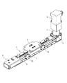
図1は、本発明に係る一実施形態の一軸アクチュエータの外観を示すものである。
本実施形態の一軸アクチュエータは、装置架台1と、装置架台1上に配置されているタイミングベルト機構2と、タイミングベルト機構2のタイミングベルト8に固定されたスライダ3と、モータ4と、モータ4の下部に連結され、モータ4の駆動力をタイミングベルト機構2に伝達する回転伝達部5と、を備えている。
DESCRIPTION OF EMBODIMENTS Hereinafter, modes for carrying out the present invention (hereinafter referred to as embodiments) will be described in detail with reference to the drawings.
FIG. 1 shows an appearance of a uniaxial actuator according to an embodiment of the present invention.
The uniaxial actuator of this embodiment includes an
タイミングベルト機構2は、図2に示すように、装置架台1の長手方向の一方に配置した従動側プーリ部6と、装置架台1の長手方向の他方に配置した駆動側プーリ部7と、これら従動側プーリ部6及び駆動側プーリ部7の間に配置されたタイミングベルト8とを備えている。
従動側プーリ部6は、装置架台1の一端に固定されたプーリケース9と、このプーリケース9に軸線が上下方向に延在して固定された軸10と、この軸10に回転自在に配置された従動側タイミングプーリ11とで構成されている。
As shown in FIG. 2, the
The driven
駆動側プーリ部7は、装置架台1の他端に固定されたプーリケース12と、このプーリケース12の内部に回転中心を上下方向に向けて配置された駆動側タイミングプーリ13とを備えている。
回転伝達部5は、駆動側プーリ部7のプーリケース12の上部に配置された筒形状のハウジング14と、ハウジング14の内部に配置した軸受15,16に回転自在に支持されてハウジング14の下部開口部から突出し、駆動側プーリ部7の駆動側タイミングプーリ13に連結されている回転伝達軸17と、ハウジング14の上部開口部からハウジング内部に挿入したモータ4のモータ軸4a及び回転伝達軸17を同軸に連結するカップリング部材18とを備えている。
The drive-
The
そして、図1に示すように、従動側プーリ部6の従動側タイミングプーリ11及び駆動側プーリ部7の駆動側タイミングプーリ13の間に、タイミングベルト8がベルト幅方向を上下方向に向けた状態で掛け渡され、このタイミングベルト8に、スライダ固定部材20を介してスライダ3が固定されている。
図2に示すように、互いに対応しているハウジング14の下部に形成されている下部開口部と、駆動側プーリ部7のプーリケース12の上部に形成されている上部開口部との間の周縁に、第1の液密シール部材21が装着されている。
As shown in FIG. 1, the
As shown in FIG. 2, the peripheral edge between the lower opening formed in the lower part of the
また、ハウジング14の上部に形成されている上部開口部の周縁と、モータ軸4aが突出している側のモータ4の端面との間に、第2の液密シール部材22が装着されている。
さらに、ハウジング14の回転伝達軸17を回転自在に支持している軸受16の上部にも、第3の液密シール部材23が装着されている。
そして、従動側タイミングプーリ11、駆動側タイミングプーリ13は、水分に対して耐腐食性を有する合成樹脂材料で形成されている。また、装置架台1、スライダ3、従動側プーリ部6のプーリケース9、軸10、駆動側プーリ部7のプーリケース12、回転伝達軸17、ハウジング14は、ステンレス等の水分に対して耐腐食性を有する金属材料で形成されている。
A second liquid-
Further, a third liquid-
The driven
本実施形態の一軸アクチュエータは、モータ4の正逆回転操作を行うことで、モータ軸4aの回転が回転伝達軸17を介して駆動側プーリ部7の駆動側タイミングプーリ13に伝達され、タイミングベルト8が回動することで、スライダ3が直線移動を行う。
次に、本実施形態の一軸アクチュエータの効果について図2及び図3を参照して説明する。
In the uniaxial actuator of this embodiment, the rotation of the
Next, the effect of the uniaxial actuator of this embodiment will be described with reference to FIGS.
図3に示すように、スライダ3を水没させて本実施形態の一軸アクチュエータを配置すると、回転伝達部5の上部に配置されているモータ4は水面の上方に位置して、モータ4に特殊な防水構造を施さなくても、十分に防水効果を確保することができる。
また、本実施形態の一軸アクチュエータで使用されているタイミングベルト8は、ベルト幅方向を上下方向に向けた状態で従動側タイミングプーリ11及び駆動側タイミングプーリ13掛け渡され、内側のベルト歯が上下方向に延在しているので、水没環境下で使用する際に水に含まれている異物がベルト歯の間に溜まり難くなり、タイミングベルト機構を正常に動作させることができる。
As shown in FIG. 3, when the
In addition, the
また、従動側タイミングプーリ11、駆動側タイミングプーリ13は、水分に対して耐腐食性を有する合成樹脂材料で形成されており、装置架台1、スライダ3、従動側プーリ部6のプーリケース9、軸10、駆動側プーリ部7のプーリケース12、回転伝達軸17、ハウジング14は、ステンレス等の水分に対して耐腐食性を有する金属材料で形成されているので、水没環境下で長期に渡って使用しても耐久性を有する一軸アクチュエータとすることができる。
Further, the driven
さらに、回転伝達部5の内部においてモータ4側に水が浸入しそうな箇所に第1〜第3の液密シール部材21、22、23を配置するだけで防水効果を高めており、一軸アクチュエータの耐荷重性や耐モーメント性などに影響を与えないので、高負荷仕様の一軸アクチュエータとして使用することができる。
Furthermore, the waterproof effect is enhanced only by disposing the first to third liquid-
1…装置架台、2…タイミングベルト機構、3…スライダ、4…モータ、4a…モータ軸、5…回転伝達部、6…従動側プーリ部、7…駆動側プーリ部、8…タイミングベルト、9…プーリケース、10…軸、11…従動側タイミングプーリ、12…プーリケース、13…駆動側タイミングプーリ、14…ハウジング、15,16…軸受、17…回転伝達軸、18…カップリング部材、20…スライダ固定部材、21…第1の液密シール部材、22…第2の液密シール部材、23…第3の液密シール部材
DESCRIPTION OF
Claims (3)
この駆動側タイミングプーリに同軸に連結されて上方に延在する回転伝達軸と、
前記装置架台の長手方向の他端に回転軸を上下方向に向けて配置した従動側タイミングプーリと、
これら駆動側及び従動側タイミングプーリの間に掛け渡したタイミングベルトと、
このタイミングベルトの一部に連結されて前記装置架台の長手方向に移動可能とされたスライダと、
前記回転伝達軸の上端でモータ軸が連結しているモータと、を備えているとともに、
前記回転伝達軸及び前記モータ軸を収容する筒状のハウジングと、前記駆動側タイミングプーリを収容するプーリケースと、を備え、
前記回転伝達軸は、前記ハウジングの下部に設けた下部開口部と、前記プーリケースの上部に設けた上部開口部を通過して前記駆動側タイミングプーリに連結しており、
互いに対応している前記ハウジングの前記下部開口部と前記プーリケースの前記上部開口部との間の周縁に第1の液密シール部材を配置したことを特徴とする一軸アクチュエータ。 A drive-side timing pulley arranged at one end in the longitudinal direction of the apparatus base with the center of rotation directed vertically.
A rotation transmission shaft that is coaxially connected to the drive side timing pulley and extends upward;
A driven-side timing pulley arranged with the rotation axis in the vertical direction at the other end in the longitudinal direction of the device base;
A timing belt spanned between the driving side and driven side timing pulleys;
A slider connected to a part of the timing belt and movable in the longitudinal direction of the apparatus base;
A motor connected to the motor shaft at the upper end of the rotation transmission shaft , and
A cylindrical housing that houses the rotation transmission shaft and the motor shaft, and a pulley case that houses the drive side timing pulley,
The rotation transmission shaft passes through a lower opening provided in the lower part of the housing and an upper opening provided in the upper part of the pulley case and is connected to the driving side timing pulley.
A uniaxial actuator , wherein a first liquid-tight seal member is disposed on a peripheral edge between the lower opening of the housing and the upper opening of the pulley case, which correspond to each other .
Priority Applications (4)
| Application Number | Priority Date | Filing Date | Title |
|---|---|---|---|
| JP2013273044A JP6361137B2 (en) | 2013-12-27 | 2013-12-27 | Single axis actuator |
| CN201480059780.5A CN105684273B (en) | 2013-12-27 | 2014-12-26 | Single axis actuator |
| PCT/JP2014/006500 WO2015098123A1 (en) | 2013-12-27 | 2014-12-26 | Uniaxial actuator |
| US15/026,077 US9759295B2 (en) | 2013-12-27 | 2014-12-26 | Single axis actuator |
Applications Claiming Priority (1)
| Application Number | Priority Date | Filing Date | Title |
|---|---|---|---|
| JP2013273044A JP6361137B2 (en) | 2013-12-27 | 2013-12-27 | Single axis actuator |
Publications (3)
| Publication Number | Publication Date |
|---|---|
| JP2015128348A JP2015128348A (en) | 2015-07-09 |
| JP2015128348A5 JP2015128348A5 (en) | 2016-04-07 |
| JP6361137B2 true JP6361137B2 (en) | 2018-07-25 |
Family
ID=53478018
Family Applications (1)
| Application Number | Title | Priority Date | Filing Date |
|---|---|---|---|
| JP2013273044A Active JP6361137B2 (en) | 2013-12-27 | 2013-12-27 | Single axis actuator |
Country Status (4)
| Country | Link |
|---|---|
| US (1) | US9759295B2 (en) |
| JP (1) | JP6361137B2 (en) |
| CN (1) | CN105684273B (en) |
| WO (1) | WO2015098123A1 (en) |
Families Citing this family (1)
| Publication number | Priority date | Publication date | Assignee | Title |
|---|---|---|---|---|
| WO2020202511A1 (en) * | 2019-04-03 | 2020-10-08 | 三菱電機株式会社 | Wrapping transmission device and robot |
Family Cites Families (7)
| Publication number | Priority date | Publication date | Assignee | Title |
|---|---|---|---|---|
| JP2006043856A (en) * | 2004-08-09 | 2006-02-16 | Oriental Motor Co Ltd | Conveying apparatus |
| JP2006083942A (en) * | 2004-09-16 | 2006-03-30 | Iai:Kk | Actuator |
| DE102010050399A1 (en) * | 2010-11-03 | 2012-05-03 | Hella Kgaa Hueck & Co. | actuator |
| JP4982593B2 (en) * | 2010-07-09 | 2012-07-25 | 日本ムーグ株式会社 | Linear actuator and swing control device for railway vehicle |
| CN201916434U (en) * | 2010-12-08 | 2011-08-03 | 无锡富瑞德精密机械有限公司 | Steel belt transmission mechanism |
| JP2012149691A (en) | 2011-01-18 | 2012-08-09 | Fujifilm Corp | Linear motion mechanism |
| JP5914931B2 (en) * | 2011-12-08 | 2016-05-11 | Smc株式会社 | Tooth skip prevention mechanism of driving force transmission belt |
-
2013
- 2013-12-27 JP JP2013273044A patent/JP6361137B2/en active Active
-
2014
- 2014-12-26 WO PCT/JP2014/006500 patent/WO2015098123A1/en active Application Filing
- 2014-12-26 CN CN201480059780.5A patent/CN105684273B/en not_active Expired - Fee Related
- 2014-12-26 US US15/026,077 patent/US9759295B2/en active Active
Also Published As
| Publication number | Publication date |
|---|---|
| US9759295B2 (en) | 2017-09-12 |
| JP2015128348A (en) | 2015-07-09 |
| WO2015098123A1 (en) | 2015-07-02 |
| CN105684273A (en) | 2016-06-15 |
| CN105684273B (en) | 2018-04-03 |
| US20160245378A1 (en) | 2016-08-25 |
Similar Documents
| Publication | Publication Date | Title |
|---|---|---|
| JP2012050824A5 (en) | ||
| US20160046020A1 (en) | Selective compliance assembly robot arm | |
| JP2010526703A (en) | Diveable device with flexible waterproof membrane | |
| KR20070098747A (en) | Electric actuator | |
| JP2008053903A5 (en) | ||
| WO2007067659A3 (en) | Rotatable tool and apparatus therefor | |
| JP2008172995A5 (en) | ||
| EP2353508A4 (en) | Ultrasonic probe | |
| JP6361137B2 (en) | Single axis actuator | |
| ATE530088T1 (en) | ELECTROMOTIVE DOUBLE FURNITURE DRIVE AND SWITCH ARRANGEMENT | |
| JP2009195305A (en) | Ultrasonic probe | |
| JP2007228688A (en) | Actuator | |
| JP5059511B2 (en) | Slider structure in robot actuator | |
| JP2003015236A5 (en) | ||
| HRP20120693T1 (en) | Sealing for fin propulsion | |
| JP5690518B2 (en) | Butterfly valve | |
| JP4850541B2 (en) | Actuator cable lead-out structure | |
| JP2011144895A5 (en) | ||
| JP5055855B2 (en) | Underwater moving device | |
| KR101398229B1 (en) | A clean type linear robot | |
| JP4816324B2 (en) | Linear movement device | |
| JP4816325B2 (en) | Linear movement device | |
| JP5269363B2 (en) | Origin return method in actuator and origin return stopper device in actuator | |
| KR101487285B1 (en) | Rudder assembly | |
| JP2007030388A5 (en) |
Legal Events
| Date | Code | Title | Description |
|---|---|---|---|
| A521 | Request for written amendment filed |
Free format text: JAPANESE INTERMEDIATE CODE: A523 Effective date: 20160217 |
|
| A621 | Written request for application examination |
Free format text: JAPANESE INTERMEDIATE CODE: A621 Effective date: 20160915 |
|
| A131 | Notification of reasons for refusal |
Free format text: JAPANESE INTERMEDIATE CODE: A131 Effective date: 20171107 |
|
| A521 | Request for written amendment filed |
Free format text: JAPANESE INTERMEDIATE CODE: A523 Effective date: 20171222 |
|
| TRDD | Decision of grant or rejection written | ||
| A01 | Written decision to grant a patent or to grant a registration (utility model) |
Free format text: JAPANESE INTERMEDIATE CODE: A01 Effective date: 20180529 |
|
| A61 | First payment of annual fees (during grant procedure) |
Free format text: JAPANESE INTERMEDIATE CODE: A61 Effective date: 20180611 |
|
| R150 | Certificate of patent or registration of utility model |
Ref document number: 6361137 Country of ref document: JP Free format text: JAPANESE INTERMEDIATE CODE: R150 |