JP4982593B2 - Linear actuator and swing control device for railway vehicle - Google Patents
Linear actuator and swing control device for railway vehicle Download PDFInfo
- Publication number
- JP4982593B2 JP4982593B2 JP2010157015A JP2010157015A JP4982593B2 JP 4982593 B2 JP4982593 B2 JP 4982593B2 JP 2010157015 A JP2010157015 A JP 2010157015A JP 2010157015 A JP2010157015 A JP 2010157015A JP 4982593 B2 JP4982593 B2 JP 4982593B2
- Authority
- JP
- Japan
- Prior art keywords
- linear motion
- linear actuator
- linear
- main body
- oil seal
- Prior art date
- Legal status (The legal status is an assumption and is not a legal conclusion. Google has not performed a legal analysis and makes no representation as to the accuracy of the status listed.)
- Active
Links
- 230000033001 locomotion Effects 0.000 claims abstract description 136
- 238000004804 winding Methods 0.000 claims abstract description 14
- 230000007246 mechanism Effects 0.000 claims abstract description 10
- 239000003921 oil Substances 0.000 claims description 62
- 239000010687 lubricating oil Substances 0.000 claims description 33
- 238000006243 chemical reaction Methods 0.000 claims description 22
- 239000012530 fluid Substances 0.000 claims description 20
- 230000002093 peripheral effect Effects 0.000 claims description 18
- 238000004891 communication Methods 0.000 claims description 7
- 230000000149 penetrating effect Effects 0.000 claims description 6
- 239000000843 powder Substances 0.000 abstract description 6
- 238000005299 abrasion Methods 0.000 abstract 1
- 239000007789 gas Substances 0.000 description 26
- 230000008859 change Effects 0.000 description 12
- 238000007789 sealing Methods 0.000 description 8
- 230000007423 decrease Effects 0.000 description 6
- 238000009434 installation Methods 0.000 description 5
- 238000013016 damping Methods 0.000 description 4
- 230000000694 effects Effects 0.000 description 4
- 238000005461 lubrication Methods 0.000 description 4
- 238000000034 method Methods 0.000 description 4
- 239000000428 dust Substances 0.000 description 3
- 239000004519 grease Substances 0.000 description 3
- 238000012423 maintenance Methods 0.000 description 3
- IJGRMHOSHXDMSA-UHFFFAOYSA-N Atomic nitrogen Chemical compound N#N IJGRMHOSHXDMSA-UHFFFAOYSA-N 0.000 description 2
- VYZAMTAEIAYCRO-UHFFFAOYSA-N Chromium Chemical compound [Cr] VYZAMTAEIAYCRO-UHFFFAOYSA-N 0.000 description 2
- XEEYBQQBJWHFJM-UHFFFAOYSA-N Iron Chemical compound [Fe] XEEYBQQBJWHFJM-UHFFFAOYSA-N 0.000 description 2
- 230000001133 acceleration Effects 0.000 description 2
- 238000013461 design Methods 0.000 description 2
- 238000010586 diagram Methods 0.000 description 2
- 238000007747 plating Methods 0.000 description 2
- 238000005096 rolling process Methods 0.000 description 2
- 235000019606 astringent taste Nutrition 0.000 description 1
- 230000015572 biosynthetic process Effects 0.000 description 1
- 238000006073 displacement reaction Methods 0.000 description 1
- 238000009826 distribution Methods 0.000 description 1
- 230000005484 gravity Effects 0.000 description 1
- 239000011261 inert gas Substances 0.000 description 1
- 238000002347 injection Methods 0.000 description 1
- 239000007924 injection Substances 0.000 description 1
- 239000000463 material Substances 0.000 description 1
- 239000000203 mixture Substances 0.000 description 1
- 238000012986 modification Methods 0.000 description 1
- 230000004048 modification Effects 0.000 description 1
- 229910052757 nitrogen Inorganic materials 0.000 description 1
- 230000010355 oscillation Effects 0.000 description 1
- 238000003825 pressing Methods 0.000 description 1
- 238000011160 research Methods 0.000 description 1
- 230000004044 response Effects 0.000 description 1
- 239000007787 solid Substances 0.000 description 1
- 238000007711 solidification Methods 0.000 description 1
- 230000008023 solidification Effects 0.000 description 1
Images


Classifications
-
- B—PERFORMING OPERATIONS; TRANSPORTING
- B61—RAILWAYS
- B61F—RAIL VEHICLE SUSPENSIONS, e.g. UNDERFRAMES, BOGIES OR ARRANGEMENTS OF WHEEL AXLES; RAIL VEHICLES FOR USE ON TRACKS OF DIFFERENT WIDTH; PREVENTING DERAILING OF RAIL VEHICLES; WHEEL GUARDS, OBSTRUCTION REMOVERS OR THE LIKE FOR RAIL VEHICLES
- B61F5/00—Constructional details of bogies; Connections between bogies and vehicle underframes; Arrangements or devices for adjusting or allowing self-adjustment of wheel axles or bogies when rounding curves
- B61F5/02—Arrangements permitting limited transverse relative movements between vehicle underframe or bolster and bogie; Connections between underframes and bogies
- B61F5/22—Guiding of the vehicle underframes with respect to the bogies
- B61F5/24—Means for damping or minimising the canting, skewing, pitching, or plunging movements of the underframes
- B61F5/245—Means for damping or minimising the canting, skewing, pitching, or plunging movements of the underframes by active damping, i.e. with means to vary the damping characteristics in accordance with track or vehicle induced reactions, especially in high speed mode
-
- H—ELECTRICITY
- H02—GENERATION; CONVERSION OR DISTRIBUTION OF ELECTRIC POWER
- H02K—DYNAMO-ELECTRIC MACHINES
- H02K7/00—Arrangements for handling mechanical energy structurally associated with dynamo-electric machines, e.g. structural association with mechanical driving motors or auxiliary dynamo-electric machines
- H02K7/06—Means for converting reciprocating motion into rotary motion or vice versa
-
- B—PERFORMING OPERATIONS; TRANSPORTING
- B61—RAILWAYS
- B61F—RAIL VEHICLE SUSPENSIONS, e.g. UNDERFRAMES, BOGIES OR ARRANGEMENTS OF WHEEL AXLES; RAIL VEHICLES FOR USE ON TRACKS OF DIFFERENT WIDTH; PREVENTING DERAILING OF RAIL VEHICLES; WHEEL GUARDS, OBSTRUCTION REMOVERS OR THE LIKE FOR RAIL VEHICLES
- B61F5/00—Constructional details of bogies; Connections between bogies and vehicle underframes; Arrangements or devices for adjusting or allowing self-adjustment of wheel axles or bogies when rounding curves
- B61F5/02—Arrangements permitting limited transverse relative movements between vehicle underframe or bolster and bogie; Connections between underframes and bogies
- B61F5/22—Guiding of the vehicle underframes with respect to the bogies
- B61F5/24—Means for damping or minimising the canting, skewing, pitching, or plunging movements of the underframes
-
- F—MECHANICAL ENGINEERING; LIGHTING; HEATING; WEAPONS; BLASTING
- F16—ENGINEERING ELEMENTS AND UNITS; GENERAL MEASURES FOR PRODUCING AND MAINTAINING EFFECTIVE FUNCTIONING OF MACHINES OR INSTALLATIONS; THERMAL INSULATION IN GENERAL
- F16H—GEARING
- F16H25/00—Gearings comprising primarily only cams, cam-followers and screw-and-nut mechanisms
- F16H25/18—Gearings comprising primarily only cams, cam-followers and screw-and-nut mechanisms for conveying or interconverting oscillating or reciprocating motions
- F16H25/20—Screw mechanisms
- F16H25/24—Elements essential to such mechanisms, e.g. screws, nuts
-
- F—MECHANICAL ENGINEERING; LIGHTING; HEATING; WEAPONS; BLASTING
- F16—ENGINEERING ELEMENTS AND UNITS; GENERAL MEASURES FOR PRODUCING AND MAINTAINING EFFECTIVE FUNCTIONING OF MACHINES OR INSTALLATIONS; THERMAL INSULATION IN GENERAL
- F16H—GEARING
- F16H57/00—General details of gearing
- F16H57/02—Gearboxes; Mounting gearing therein
- F16H57/029—Gearboxes; Mounting gearing therein characterised by means for sealing the gearboxes, e.g. to improve airtightness
-
- F—MECHANICAL ENGINEERING; LIGHTING; HEATING; WEAPONS; BLASTING
- F16—ENGINEERING ELEMENTS AND UNITS; GENERAL MEASURES FOR PRODUCING AND MAINTAINING EFFECTIVE FUNCTIONING OF MACHINES OR INSTALLATIONS; THERMAL INSULATION IN GENERAL
- F16H—GEARING
- F16H25/00—Gearings comprising primarily only cams, cam-followers and screw-and-nut mechanisms
- F16H25/18—Gearings comprising primarily only cams, cam-followers and screw-and-nut mechanisms for conveying or interconverting oscillating or reciprocating motions
- F16H25/20—Screw mechanisms
- F16H2025/2062—Arrangements for driving the actuator
- F16H2025/2075—Coaxial drive motors
- F16H2025/2078—Coaxial drive motors the rotor being integrated with the nut or screw body
-
- Y—GENERAL TAGGING OF NEW TECHNOLOGICAL DEVELOPMENTS; GENERAL TAGGING OF CROSS-SECTIONAL TECHNOLOGIES SPANNING OVER SEVERAL SECTIONS OF THE IPC; TECHNICAL SUBJECTS COVERED BY FORMER USPC CROSS-REFERENCE ART COLLECTIONS [XRACs] AND DIGESTS
- Y10—TECHNICAL SUBJECTS COVERED BY FORMER USPC
- Y10T—TECHNICAL SUBJECTS COVERED BY FORMER US CLASSIFICATION
- Y10T74/00—Machine element or mechanism
- Y10T74/18—Mechanical movements
- Y10T74/18568—Reciprocating or oscillating to or from alternating rotary
- Y10T74/18576—Reciprocating or oscillating to or from alternating rotary including screw and nut
- Y10T74/18664—Shaft moves through rotary drive means
Abstract
Description
本発明は、リニアアクチュエータ、特に、鉄道車両等の車両に装着され、電磁力によって車両の振動や揺動を制振する中空モータを使用したリニアアクチュエータ、及び、該リニアアクチュエータを有する鉄道車両用の揺動制御装置に関する。 The present invention relates to a linear actuator, in particular, a linear actuator that uses a hollow motor that is mounted on a vehicle such as a railway vehicle and that controls vibrations and oscillations of the vehicle by electromagnetic force, and a railway vehicle having the linear actuator. The present invention relates to a swing control device.
鉄道車両等の車両の走行中に発生する振動や揺動を抑制するために、リニアアクチュエータが使用されている。車両の進行方向に対して横方向の振動、揺動を抑制することは、乗客の乗り心地を快適にし、安全な走行条件を維持するために重要な役割を果たす。近年、特に、高速走行時における空力特性の影響による揺動や振動を、アクティブ制御で抑制し車両姿勢を安定維持させる研究が進められている。また、一般に、鉄道車両の揺動防止のために使用されるリニアアクチュエータは、頻繁な交換等のメンテナンスが実行しにくい過酷な条件下で使用されるにも関わらず、設置される使用環境の温度変化は大きい(例えば−20℃〜60℃)という過酷な温度条件で使用されるため、リニアアクチュエータの機能を安定して維持することが要求される。 Linear actuators are used to suppress vibrations and swings that occur during travel of vehicles such as railway vehicles. Suppressing vibrations and swaying in the lateral direction with respect to the traveling direction of the vehicle plays an important role in making passengers comfortable and maintaining safe driving conditions. In recent years, in particular, research is being conducted to suppress the swinging and vibration due to the influence of aerodynamic characteristics during high-speed traveling by active control and to maintain a stable vehicle posture. In general, linear actuators used to prevent railcars from swinging are used under harsh conditions where maintenance such as frequent replacement is difficult to perform, but the temperature of the environment in which they are installed is used. Since the change is used under severe temperature conditions (for example, −20 ° C. to 60 ° C.), it is required to stably maintain the function of the linear actuator.
特許文献1は、車体の横方向動揺に抗する力を生じさせる車両用気体圧サーボシリンダを開示している。特許文献1の構成によると、車両は台車上に空気ばねを介して搭載され、車両の下部に設置されたセンタリングピンと台車との間に車両用空気圧サーボシリンダが水平方向に設置され、空気圧発生部が車両用空気圧サーボシリンダの外部に設置され、サーボシリンダの駆動源として圧縮空気を供給していることが記載されている。 Patent Document 1 discloses a vehicular gas pressure servo cylinder that generates a force that resists lateral shaking of a vehicle body. According to the configuration of Patent Document 1, a vehicle is mounted on a carriage via an air spring, a vehicle pneumatic servo cylinder is installed in a horizontal direction between a centering pin installed at the lower part of the vehicle and the carriage, and an air pressure generating unit Is installed outside the pneumatic servo cylinder for vehicles and supplies compressed air as a drive source of the servo cylinder.
特許文献2が開示する車体の振動を抑制する鉄道車両用制御装置は、電動アクチュエータを車体と台車の間に設置し、電動アクチュエータによる駆動力を制御することにより、アクチュエータ及びダンパとしての機能を持たせている。電動アクチュエータとしては、モータの回転をボールねじやローラねじ等を用いて直線運動に変換する機構を有し、この変換部の摩擦等の抵抗でダンパの減衰力と同じ役割を担わせていることが記載されている。
引用文献1に係る車両用気体圧サーボシリンダは、車両用気体圧サーボシリンダの本体以外の場所に、気体圧発生部を有し、また、車両用気体圧サーボシリンダ本体と気体圧発生部との間には、配管を配設することが必要であり、全体としてコンパクトな装置を実現することはできない。 The vehicular gas pressure servo cylinder according to the cited document 1 has a gas pressure generating portion at a place other than the vehicular gas pressure servo cylinder main body, and includes a vehicular gas pressure servo cylinder main body and the gas pressure generating portion. It is necessary to dispose piping between them, and a compact device as a whole cannot be realized.
また、引用文献2に係る鉄道車両用制御装置は、ボールねじ11a或いはローラねじ11a等による直動生成機構とモータ12が、該鉄道車両用制御装置の直動方向に直列して配置されているため、装置のコンパクト化を実現することはできないという課題を有する。この構成は、図11に例示することができるように、駆動部(モータ)と回転/直動変換部がシリンダストロークの伸長方向に直列に配置されている。このため、リニアアクチュエータのストローク方向の大きさを短縮することは困難である。
Further, in the railway vehicle control device according to the cited
本発明は、リニアアクチュエータ本体以外に圧力発生装置のような外部装置を必要とせず、また、圧力流体での制御装置の場合に必要な駆動源である加圧流体の配管の設置を必要としない、コンパクトなリニアアクチュエータであって、必要なときに、所望の駆動力または所望の減衰力を与えるリニアアクチュエータとしての機能を提供し、また、リニアアクチュエータとして機能させる必要のないときには、外力に対して大きな負荷(バックドライブフォース)を与えることなく、容易に従動することができるリニアアクチュエータを提供することを目的とする。また、頻繁な交換等のメンテナンスが実行しにくく、設置される使用環境での温度変化が大きい(−20℃〜60℃)という過酷な使用条件下でも、低温での潤滑油の粘性増大によるバックドライブフォースの増大の影響を排除し、バックドライブフォースが低い状態で安定して機能するリニアアクチュエータを提供することを目的とする。 The present invention does not require an external device such as a pressure generating device other than the linear actuator main body, and does not require the installation of a pressurized fluid piping which is a driving source necessary in the case of a control device using a pressure fluid. A compact linear actuator that provides a function as a linear actuator that provides a desired driving force or a desired damping force when necessary, and is not required to function as a linear actuator. An object of the present invention is to provide a linear actuator that can be easily driven without applying a large load (back drive force). In addition, it is difficult to perform maintenance such as frequent replacement, and even under severe usage conditions where the temperature change in the installation environment is large (−20 ° C. to 60 ° C.), back-up due to increased viscosity of lubricating oil at low temperature An object of the present invention is to provide a linear actuator that eliminates the influence of an increase in drive force and functions stably with a low back drive force.
本発明のリニアアクチュエータは、開口端部と閉塞端部を有する中空構造の本体と、該本体内の閉塞端部側に固定され、開口端部側に開口端を有する円筒シリンダと、一方の端部は該本体の該開口端部から延出し、他方の端部は外周部にウエアリングを有し、該ウエアリングは軸方向に摺動可能に該円筒シリンダ内に収容され、該開口端部側の外周に該開口端部の直動オイルシールを介して軸方向に摺動可能な摺動部を有し、該直動オイルシールと該摺動部は該本体の内部を密閉する、直動ロッドと、該直動ロッドの軸を中心として回転可能に該本体内に支持された回転中空シャフトと、を有し、
該回転中空シャフトは外周面の一部に永久磁石を有し、該本体はその内表面の該永久磁石と対面する位置にステータ巻線部を有し、該永久磁石と該ステータ巻線部は中空モータを構成し、該回転中空シャフトは同軸で固定されたナット部を有し、該直動ロッドは該摺動部と該ウエアリングの間の外周面に該ナット部と係合するねじ部を有し、該ナット部と該ねじ部は係合して回転中空シャフトが回転することにより該直動ロッドが軸方向に直動する回転直動変換機構を構成し、該ナット部の該直動ロッドの軸方向における両側において、該回転中空シャフトと該本体に固定された部材との間をシールする2箇所の回転オイルシール部を有し、該回転オイルシール部は、該直動ロッドが直動する該本体内の領域であって潤滑油と気体の混在する第1密閉領域を、該中空モータが配置された第2密閉領域から分離して画定するとともに、該直動オイルシール部と協働して該第1密閉領域を密封する、ことを特徴とする。
The linear actuator of the present invention includes a hollow structure main body having an open end and a closed end, a cylindrical cylinder fixed to the closed end in the main body and having an open end on the open end, and one end The portion extends from the opening end of the main body, and the other end has a wear ring on the outer peripheral portion. The wear ring is accommodated in the cylindrical cylinder so as to be slidable in the axial direction. A sliding portion that is slidable in the axial direction through a linear motion oil seal at the opening end, and the linear motion oil seal and the sliding portion seal the interior of the main body. A moving rod, and a rotating hollow shaft supported in the main body so as to be rotatable about the axis of the linear rod.
The rotating hollow shaft has a permanent magnet on a part of the outer peripheral surface, the main body has a stator winding portion at a position facing the permanent magnet on the inner surface, and the permanent magnet and the stator winding portion are The rotating hollow shaft has a nut portion that is coaxially fixed, and the linearly acting rod is a screw portion that engages with the nut portion on the outer peripheral surface between the sliding portion and the wear ring. The nut portion and the screw portion are engaged to form a rotation / linear motion conversion mechanism in which the linear motion rod linearly moves in the axial direction by rotating the rotating hollow shaft, and the nut portion On both sides in the axial direction of the moving rod, it has two rotating oil seal portions that seal between the rotating hollow shaft and a member fixed to the main body. This is a region in the main body that moves linearly, and a mixture of lubricating oil and gas. The first closed area, as well as defining separately from the second closed region hollow motor is arranged to seal the first sealing area in cooperation with the linear motion oil seal portion, characterized in that.
本発明に係る鉄道車両用の揺動制御装置は、鉄道車両の台車と車体の間に設置された前記リニアアクチュエータと、車体の揺動を抑制するようにリニアアクチュエータの駆動をアクティブに制御する制御装置とを有する、ことを特徴とする。 According to the present invention, there is provided a swing control device for a railway vehicle, wherein the linear actuator installed between the bogie and the vehicle body of the railway vehicle, and a control for actively controlling the drive of the linear actuator so as to suppress the swing of the vehicle body. And a device.
リニアアクチュエータ本体以外に圧力発生装置のような外部装置を必要とせず、また、圧力流体での制御装置の場合にあるような駆動源である加圧流体の配管の設置を必要としない、コンパクトなリニアアクチュエータを実現し、必要なときに所望の駆動力を与えるアクチュエータとして、または所望の減衰力を与えるリニアアクチュエータとしての機能を提供し、また、リニアアクチュエータとして機能させる必要のないときには、外力に対して大きな抗力を与えることなく、容易に従動することができる。また、温度等の使用環境に依らず安定してリニアアクチュエータとして機能することができる。 Compact and does not require an external device such as a pressure generator in addition to the linear actuator body, and does not require the installation of pressurized fluid piping, which is a drive source as in the case of a control device using pressure fluid. Provides a function as an actuator that realizes a linear actuator and gives a desired driving force when necessary, or a linear actuator that gives a desired damping force, and against an external force when it is not necessary to function as a linear actuator And can follow easily without giving a big drag. Further, it can function as a linear actuator stably regardless of the usage environment such as temperature.
以下、添付の図面を参照しながら、本発明に係る流体弁駆動機構を説明する。 Hereinafter, a fluid valve drive mechanism according to the present invention will be described with reference to the accompanying drawings.
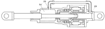
実施例1に係るリニアアクチュエータの断面図であって、最小ストロークの場合を図1に、最大ストロークの場合を図2に示す。図1及び2の断面図を参照しながら、本実施例のリニアアクチュエータの構成を説明する。 FIG. 1 is a cross-sectional view of a linear actuator according to a first embodiment, and FIG. 1 shows a case of a minimum stroke and FIG. 2 shows a case of a maximum stroke. The configuration of the linear actuator of this embodiment will be described with reference to the cross-sectional views of FIGS.
本発明のリニアアクチュエータは、開口端部及び閉塞端部を有する中空構造の本体を有する。図1及び2に示すように、本体は、直動軸受け部ケーシング12aと、回転直動変換部ケーシング12bと、モータ部ケーシング12cと、モータ部後部ケーシング12dと、円筒シリンダ12eと、シリンダ後端部ケーシング12fとから構成される。
The linear actuator of the present invention has a hollow main body having an open end and a closed end. As shown in FIGS. 1 and 2, the main body includes a linear motion bearing
本発明のリニアアクチュエータは、本体内の閉塞端部側に固定され開口端部側に開口端を有する円筒シリンダ23と、直動ロッド2を有する。
The linear actuator of the present invention includes a
直動ロッド2は、一方の端部が本体の開口部(直動軸受け部ケーシング12a)から本体外へ延出し、開口端部側の外周面に本体の開口部の直動オイルシール3を介して直動ロッド2の軸方向に摺動可能な摺動部6aを有する。直動オイルシール3と摺動部6aによって、本体の内部は密封されている。直動ロッド2は、直動軸受け部ケーシング12aの直動軸受け4により軸方向に直動可能に支持されている。直動ロッド2は、他方の端部の外周部にウエアリングホルダ22aを介してウエアリング22を有し、直動ロッド2の他方の端部は、ウエアリング22が軸方向に摺動可能な状態で、円筒シリンダ23に収容されている。
One end of the
さらに、本発明のリニアアクチュエータは、本体内に備えられた回転支持部であるアンギュラベアリング9によって、直動ロッド2と同軸に回転可能に本体内に支持された回転中空シャフト10を有する。アンギュラベアリング9は、ベアリング固定ナット8により回転中空シャフト10に固定される。
Furthermore, the linear actuator of this invention has the rotation
回転中空シャフト10は、外周面の一部にロータ永久磁石20を備える。一方、本体の一部であるモータ部ケーシング12cの内表面には、回転中空シャフト10のロータ永久磁石20と対面する位置にステータ巻線部11を有する。ロータ永久磁石20とステータ巻線部11は中空モータを構成する。13a、13bはそれぞれ、VR型レゾルバ(可変リラクタンス型レゾルバ)のステータ部、ロータ部であり、ロータとしての回転中空シャフトの回転角を検出し、不図示の制御装置に出力し、モータの駆動制御に使用される。
The rotating
回転中空シャフト10は、内周面の一部に遊星ローラねじのナット部17を備える。該ナット部17は、ナット固定リング7によって回転中空シャフト10に対して回転中空シャフト10と同軸に固定される。一方、直動ロッド2は、摺動部6aとウエアリング22の間の外周面に、遊星ローラねじのナット部17と係合する係合部である遊星ローラねじのねじ部6bを有する。該ナット部17と該ねじ部6bは互いに係合して、回転直動変換機構である遊星ローラねじを構成する。回転中空シャフト10が回転することにより遊星ローラねじを介して直動ロッド2は軸方向に直動する。本実施例においては、遊星ローラねじによって回転直動変換機構を実現しているが、本発明はこれに限定されることはなく、ボールねじ等、他の回転運動を直動運動に変換する機能を有する機構を使用してもよい。
The rotary
図3に、図1のIII−IIIから見た本実施例のリニアアクチュエータの遊星ローラねじのナット部17の拡大部分断面図を示す。回転中空シャフト10の内面に固定された該ナット部17は、複数のローラ17aを有し、ねじ部6bのねじ溝6cと係合する。また、ナット部17は、軸方向に貫通する複数の貫通孔17bを備え、潤滑油がナット部17の貫通孔17bを経由して軸方向に移動しやすい構成を提供している。
FIG. 3 shows an enlarged partial cross-sectional view of the
図4に、図1のIV−IVから見た実施例1に係るリニアアクチュエータのウエアリングホルダ22bの部分を拡大した部分断面図を示す。ウエアリング22を支持するウエアリングホルダ22aは、その外周に凹部を有し、該凹部によりウエアリング22を支持する。また、ウエアリングホルダ22aは、軸方向に貫通するウエアリングホルダ貫通孔22bを有し、ウエアリングホルダ貫通孔22bによって、ウエアリングホルダ22aは軸方向に流体連通している。
FIG. 4 shows an enlarged partial cross-sectional view of a portion of the
遊星ローラねじのナット部17の軸方向における両側において、本体に対して固定された部材である第1の円筒シャフト15及び第2の円筒シャフト19と回転中空シャフト10との間をシールする、第1のオイルシール16及び第2のオイルシール18を有する。第1及び第2の円筒シャフト15,19と第1及び第2のオイルシール16,18は、それぞれ協働して、第1の回転オイルシール部及び第2の回転オイルシール部を形成する。第1の回転オイルシール部15、16及び第2の回転オイルシール部18、19は、直動ロッド2が直動する本体内の空間であって潤滑油と気体が混在する第1密閉領域5を、中空モータ11,20及び回転支持部であるアンギュラベアリング9が配置された第2密閉領域21から分離して画定する。さらに、直動オイルシール3と協働して第1密閉領域5を密封する。第1及び第2の円筒シャフト15、19の外周面は、その面上を第1及び第2のオイルシール16,18が摺動するので、耐摩耗性を持たせるために硬質クロムメッキ等を施すことが望ましい。第1及び第2のオイルシール16,18は、ゴム等の材料から構成される。
The first
本発明に係るリニアアクチュエータは、ステータ巻線部11とロータ永久磁石20からなる中空モータを駆動源とするため、従来例として示した例のように駆動部と回転/直動変換部がシリンダストロークの伸長方向に直列に配置されることがない。このため、本発明のリニアアクチュエータは、シリンダのストローク方向にコンパクト化することができる。
Since the linear actuator according to the present invention uses a hollow motor including the
図1に示した最小ストローク時、及び図2に示した最大ストローク時における本実施例のリニアアクチュエータの断面図を参照しながら、本リニアアクチュエータの動作と機能について説明する。 The operation and function of this linear actuator will be described with reference to cross-sectional views of the linear actuator of this embodiment at the minimum stroke shown in FIG. 1 and at the maximum stroke shown in FIG.
図1に示した最小ストロークの状態において、不図示の制御装置により中空モータが所定の回転方向に駆動され、ロータ永久磁石20がステータ巻線部11に対して回転すると、それに伴い、回転中空シャフト10、及び回転中空シャフト10に固定されている遊星ローラねじのナット部17が回転する。ナット部17が回転すると、それと係合しているねじ部6bによって、直動ロッド2は軸方向に直動する。ここで、直動ロッド2の端部に固定されている第1の球面軸受け1及び本体のシリンダ後端部ケーシング12fに固定されている第2の球面軸受け14は、本リニアアクチュエータで制御しようとする部材、例えば、列車の車両と台車、に接続され、直動ロッド2の軸を中心とした回転方向の動きは拘束されている。したがって、遊星ローラねじのナット部17の回転は、それと係合している遊星ローラねじのねじ部6bによって、直動ロッド2の軸方向の直動運動に変換される。
In the state of the minimum stroke shown in FIG. 1, when the hollow motor is driven in a predetermined rotation direction by a control device (not shown) and the rotor
直動ロッド2が軸方向に直動するとき、円筒シリンダ23内に収容されている直動ロッド2の端部の外周のウエアリング22は、円筒シリンダ23の内周面と摺動しながら、円筒シリンダ23内を直動する。本リニアアクチュエータ自体が振動を受けた時のモーメントや、重力に対する設置角度に依存する自重によるモーメントは、直動軸受け部ケーシング12aの直動軸受け4と直動ロッド4の摺動部6a、遊星ローラねじのナット部17と直動ロッド2の遊星ローラねじのねじ部6b、及び、直動ロッド2のウエアリング22と円筒シリンダ23の内周面とで受ける。本発明にかかるリニアアクチュエータにおいては、ステータ巻線部11とロータ永久磁石20からなる中空モータ部を、軸方向の中心に対して本体内の第2の端部側(第2の球面軸受け側)に配置しているため、加えられた振動等により発生する慣性モーメントを小さく抑えることができる。これにより、リニアアクチュエータの設計耐荷重を小さくすることができるという効果を有する。
When the
直動ロッド2が直動軸受け部ケーシング12aから延出し、図1のストローク最小の状態から図2のストローク最大の状態に変化することにより、第1密閉領域5の容積は増大する。また、第1密閉領域5は、第1と第2の回転オイルシール部15、16、18、19と直動オイルシール部3とによって密封されているため、この容積の増大により、第1密閉領域5内の圧力は低下する。遊星ローラねじのねじ部6bとナット部17、ウエアリング22と円筒シリンダ23の内面との摺動部、及び、直動軸受け部ケーシング12aの直動軸受け4と直動ロッド2の摺動部6aとの間の潤滑のために、第1密閉領域5内には潤滑油が封入されている。密閉空間である第1密閉領域5への直動ロッド2の出入りを可能とするため、第1密閉領域5内に潤滑油とともに気体を封入し、第1密閉領域5内の圧力の変動をバッファしている。本発明のリニアアクチュエータは、直動ロッド2の軸方向が略水平になるように設置して使用されるため、第1密閉領域5の一部である円筒シリンダ23内にも潤滑油と気体が存在する。直動ロッド2が直動するときには、ウエアリング22は円筒シリンダ23の内面に対して摺動しながら移動し、円筒シリンダ23内の軸方向におけるウエアリング22の移動時における圧力差に応じて、潤滑油及び気体は、ウエアリングホルダ22aを軸方向に貫通しているウエアリングホルダ貫通孔22bを介して、円筒シリンダ23内の軸方向に移動する。
The
円筒シリンダ23内面は、硬質クロムメッキ等により耐摩耗性の向上が図られている。また、円筒シリンダ23内面の損耗が進行した場合には、シリンダ後端部ケーシング12f(円筒シリンダ23)のみを交換することにより、直動ロッド2のウエアリング22と円筒シリンダ23内面との良好な摺動特性を簡易な部品交換によって維持することができるという効果を有する。
The inner surface of the
鉄道車両の揺動防止に本発明のリニアアクチュエータを用いる場合、特に高速走行時の空力特性のために必要となるアクティブ制御がある。例えば、低速走行では発生しないが、高速走行におけるトンネル進入時の瞬時的な車両の横揺れ、或いは、高速走行時のカルマン渦の影響による列車編成の最終車両における横揺れ等がある。これらの揺動を抑制するため、所定の走行速度以下など、所定の条件以外ではアクティブ制御は不要である場合があり、リニアアクチュエータの電源を切った状態で、できるだけ外力に対し負荷(バックドライブフォース)を与えることなく従動させたいというニーズがある。 When the linear actuator of the present invention is used to prevent the railcar from swinging, there is active control necessary for aerodynamic characteristics particularly during high-speed traveling. For example, although it does not occur in low-speed traveling, there is instantaneous rolling of the vehicle when entering a tunnel in high-speed traveling or rolling in the final vehicle of train formation due to the influence of Karman vortex during high-speed traveling. In order to suppress these swings, active control may not be necessary except for a predetermined condition such as a predetermined traveling speed or less, and the load (back drive force) is applied to the external force as much as possible with the linear actuator turned off. ) There is a need to follow without giving.
本発明の構成においては、第1及び第2の回転オイルシール部の摺動部は、直動ロッド2の係合部の径の1.5倍以下の径、さらに好ましくは、1.3倍以下の径とすることにより、さらに好ましくは、1.15倍以下の径とすることにより、第1及び第2の回転オイルシール部での摺動断面積を小さくし、外力に対し小さな負荷で従動させることができる。このシール部の摺動部分の径が、直動ロッド2の係合部の系に対して大きすぎる場合は、シール部の摺動長(摺動断面積)が増大し、外力に従動させる場合の負荷が大きくなり好ましくない。逆に、第1及び第2の回転オイルシール部の摺動部の径を小さくしすぎると、シール部の摺動長(摺動断面積)に起因する外力に対する負荷は小さくすることができるが、第1及び第2の円筒シャフト15,19の内面と直動ロッド2(遊星ローラねじのねじ部6b)の外面の間隔が狭くなるため、直動ロッド2のストロークが変化して第1密閉領域5内の圧力が変動する時に、この隙間を介して移動する潤滑油の流体抵抗が増大し、アクチュエータの駆動抵抗を増加させ、バックドライブフォースを増大させるので好ましくない。
In the configuration of the present invention, the sliding portion of the first and second rotary oil seal portions has a diameter that is 1.5 times or less, more preferably 1.3 times the diameter of the engaging portion of the
また、本発明のリニアアクチュエータにおいては、摩耗粉等が発生しやすい遊星ローラねじのねじ部6b,ナット部17、直動軸受け4は、オイルで潤滑し、摩耗粉等が発生した場合でも、オイルの粘性が低いため、摩耗粉が発生した場所に摩耗粉を局所的に偏在させることなく分散させることができるため、軸受け部の固渋等の危険を回避することができる。
Further, in the linear actuator of the present invention, the
一方、第1及び第2の回転オイルシール部(15,16,18,19)で密封された第2密閉領域21(21a,21b)内に備えられた回転支持部であるアンギュラベアリング9は、低粘度グリスで潤滑する。リニアアクチュエータの電源がOFFの時に、外力に対し小さな負荷で従動させるためには、アンギュラベアリング9もオイルで潤滑することが好ましいが、第2密閉領域21内には、モータ部(ステータ巻線部11、ロータ永久磁石20)があるため、アンギュラベアリング9で発生した摩耗粉等の鉄粉が流動してモータ部に移動してしまう危険性をできるだけ排除するために、低粘度グリスを使用する。アンギュラベアリング9とモータ部の間には、非接触ラビリンスシール27を設け、低粘度グリスで封止し、ロータ永久磁石20とステータ巻線部11とVRレゾルバ13a,13bを含むモータ領域21bと、アンギュラベアリング9を含むベアリング領域21aを分離し、アンギュラベアリング9で発生した摩耗粉等の鉄粉がモータ領域21bへ侵入する危険性を排除している。また、この非接触ラビリンスシール27は、回転中空シャフト10に対して、回転軸から半径方向の外側に設置されるため、シール部分の周長は長いが、非接触のシールであるため、外力に対し小さな負荷で従動できる。
On the other hand, the
本発明のリニアアクチュエータにおいては、直動ロッド2が移動する第1密閉領域5は、第1と第2の回転オイルシール部15、16、18、19と直動オイルシール部3とによって密封されているため、直動ロッド2のストローク変位に起因する第1密閉領域5内の圧力変動によって、外気を第1密閉領域5内に流出入させることがない(エアブリーザ機能を有さない)。このため、−20度のような低温の条件下で使用し続けても、空気中の水分の凝固等の現象に起因する摺動機能の低下を招くことはなく、良好な摺動状態を維持することができるという効果を有する。また、本発明のリニアアクチュエータ本体は外気に対して密封されているため、空気中の水分・埃塵等が本体内へ侵入することを防止でき、安定した機能を維持することができる。ストローク変化によって本体の先端部である直動軸受け部ケーシング12aから突出したときに、直動ロッド2の摺動部6aが周囲の環境に曝され水分やダスト等が摺動部6aの外表面に付着することを防止するため、直動軸受け部ケーシング12aと第1の球面軸受け1の間には、不図示の蛇腹等のカバーを設け、粉塵等が摺動部6aの外表面に付着することを未然防止することが好ましい。
In the linear actuator of the present invention, the first sealed region 5 in which the
なお、第1密閉領域5内の気体は、空気或いは窒素等の不活性ガスを使用することができる。 In addition, the gas in the 1st sealing area | region 5 can use inert gas, such as air or nitrogen.
第1密閉領域5は密閉空間であるので、気体が占める容積と圧力の積は一定である。したがって、第1密閉領域5内の気体が占める容積がV1からV2に変化し、圧力がP1からP2に変化した場合、容積変化後の圧力P2は、
P2=P1×(V1/V2)
=P1×(V1/(V1±ΔV)) (1)
で表すことができる。ここで、ΔVは気体が占める容積のV1からV2への変化量(V2−V1)であり、直動ロッド2が直動軸受け部ケーシング12aに対して出入りする体積に相当する量である。言い換えると、直動ロッド2の摺動部6aの断面積と最大ストローク長の積で表される体積である。この関係により、直動ロッド2の最大ストローク時と最小ストローク時の第1密閉領域5内の圧力差を考慮して、オイルシール部の耐圧条件を満足するように装置を設計することができる。一般的なオイルシールにおいて推奨される許容差圧条件は0.3気圧程度である。したがって、第1密閉領域5内及び第2密閉領域21内の圧力の初期条件を大気圧とした場合、
V/(V−A×L)<1.3 (2)
の条件を満たすように、第1密閉領域5の容積と潤滑油の量から決まる最大ストローク時の気体の容積V、直動ロッド2の軸方向に垂直な平面内での断面積Aとストローク長さLを考慮して設計することができる。これにより、第1密閉領域5内の密閉性を維持するとともに、オイルシールの機能を損なうことなく安定した機能を維持できるリニアアクチュエータを提供できる。
Since the first sealed region 5 is a sealed space, the product of the volume occupied by the gas and the pressure is constant. Therefore, when the volume occupied by the gas in the first sealed region 5 changes from V1 to V2 and the pressure changes from P1 to P2, the pressure P2 after the volume change is
P2 = P1 × (V1 / V2)
= P1 × (V1 / (V1 ± ΔV)) (1)
Can be expressed as Here, ΔV is a change amount (V2−V1) of the volume occupied by the gas from V1 to V2, and is an amount corresponding to the volume of the
V / (V−A × L) <1.3 (2)
The gas volume V at the maximum stroke determined from the volume of the first sealed region 5 and the amount of lubricating oil, the cross-sectional area A and the stroke length in the plane perpendicular to the axial direction of the
(本実施例のリニアアクチュエータの組み立て方法)
以下、図5A乃至5Iを参照しながら、本実施例に係るリニアアクチュエータの組み立て方法の一例を説明する。
(Assembly method of the linear actuator of this embodiment)
Hereinafter, an example of a method for assembling the linear actuator according to the present embodiment will be described with reference to FIGS. 5A to 5I.
最初に、アンギュラベアリング9の内輪をベアリング固定ナット8で回転中空シャフト10に固定し、回転中空シャフト10には、ロータ永久磁石20、第2のオイルシール18が装着される。また、ナット固定リング7により、遊星ローラねじのナット部17が回転中空シャフト10の内周面に固定される。また、第1のオイルシール16が、ナット固定リング7に対して固定される(図5A参照)。本体の一部を構成する回転直動変換部ケーシング12bには、第1の円筒シャフト15が設置される(図5A参照)。
First, the inner ring of the
次に、第1の円筒シャフト15の外周面に第1のオイルシール16を摺動させながら、アンギュラベアリング9を介して回転中空シャフト10を回転直動変換部ケーシング12bに挿入し、アンギュラベアリング押え板28によって、アンギュラベアリング9の外輪を回転直動変換部ケーシング12bに固定する。また、非接触ラビリンスシール27をアンギュラベアリング押え板28と回転中空シャフト10の間に設置する(図5B)。
Next, while the
中空モータのステータ巻線11、VRレゾルバ(ステータ側)13aが固定されたモータ部ケーシング12cを回転直動変換部ケーシング12bへ連結する(図5C)。次に、VRレゾルバ(ロータ側)13bを回転中空シャフト10に固定した後、モータ部後部ケーシング12dをモータ部ケーシング12cの端部に固定する(図5D)。
The
直動ロッド2と遊星ローラねじのねじ部6bとを連結し、回転直動変換部ケーシング12bの開口部側から、遊星ローラねじのねじ部6bのねじ溝6cをナット部17と係合させながら挿入する(図5E)。
The
次に、予め第2の円筒シャフト19を端部に固定した円筒シリンダ23を、モータ部後部ケーシング12dの中央の開口部から挿入し、第2の円筒シャフト19を第2のオイルシール18に対して摺動させながら第2のオイルシール18に挿入し、円筒シリンダ23をモータ部後部ケーシング12dに固定する(図5F)。
Next, a
次に、直動ロッド2と遊星ローラねじのねじ部6bを円筒シリンダ23の端部側に移動させ、ウエアリング22を外周の凹部に装着したウエアリングホルダ22aを直動ロッド2の遊星ローラねじのねじ部6b側の端部に装着し、ウエアリングホルダ固定ナット22cにより、直動ロッド2の遊星ローラねじのねじ部6b側の端部に固定する(図5G)。
Next, the
次に、直動ロッド2の摺動部6aと、直動オイルシール3及び直動軸受け4が固定された直動軸受け部ケーシング12aを摺動させながら、直動ロッド2の摺動部6aを直動軸受け部ケーシング12aに挿入するように、直動軸受け部ケーシング12aを装着し、回転直動変換部ケーシング12bに対して固定する(図5H)。
Next, while sliding the sliding portion 6a of the
最後に、第1の球面軸受け1を直動ロッド2の先端部に固定し、シリンダ後端部ケーシング12fを円筒シリンダ23の端部に固定し、第2の球面軸受け14をシリンダ後端部ケーシング12fに固定する(図5I)。
Finally, the first spherical bearing 1 is fixed to the tip of the
また、潤滑油は、回転直動変換部ケーシング12b等に構成された不図示の密閉閉鎖可能なオイル注入口から必要量を注入することができる。
Further, the required amount of lubricating oil can be injected from an oil injection port (not shown) that can be hermetically closed and configured in the rotation / linear motion
以上説明したように、本実施例の構成により、リニアアクチュエータ本体以外に圧力発生装置のような外部装置を必要とせず、また、圧力流体での制御装置の場合に必要である加圧流体の配管を必要とせず、中空モータを使用することによりコンパクトなリニアアクチュエータを実現することができる。また、必要なときに所望の駆動力を与えるアクチュエータとして、または所望の減衰力を与えるリニアアクチュエータとしての機能を提供し、また、リニアアクチュエータとして機能させる必要のないときには、外力に対して大きな抗力を与えることなく、容易に従動することができる。また、温度等の使用環境に依らず安定して機能を維持可能なリニアアクチュエータを実現することができる。 As described above, the configuration of this embodiment does not require an external device such as a pressure generating device other than the linear actuator body, and is also necessary for a pressurized fluid control device. Therefore, a compact linear actuator can be realized by using a hollow motor. In addition, it provides a function as an actuator that gives a desired driving force when necessary or as a linear actuator that gives a desired damping force. When it is not necessary to function as a linear actuator, it provides a large resistance against external forces. It can be easily followed without giving. Further, it is possible to realize a linear actuator that can stably maintain its function regardless of the usage environment such as temperature.
実施例2に係るリニアアクチュエータの断面図で、最小ストロークの場合を図6に、最大ストロークの場合を図7に示す。
本実施例のリニアアクチュエータの構成は、図1乃至3で示した実施例1のリニアアクチュエータと基本的には同じであるので、同じ構成については説明を省略し、異なる構成についてのみ説明する。
FIG. 6 is a cross-sectional view of the linear actuator according to the second embodiment, and FIG. 6 shows the case of the minimum stroke and FIG. 7 shows the case of the maximum stroke.
Since the configuration of the linear actuator of the present embodiment is basically the same as that of the linear actuator of Embodiment 1 shown in FIGS. 1 to 3, the description of the same configuration is omitted, and only a different configuration is described.
本実施例の円筒シリンダ23は、直動ロッド2のウエアリング22の閉塞端部側の可動範囲外の上部に開口部26を有する。本体の一部である回転直動変換部ケーシング12bは、遊星ローラねじのナット部17の開口端部側の上部に開口部24を有する。円筒シリンダ23の開口部26と、第1密閉領域5を構成する本体の一部である回転直動変換部ケーシング12bの開口部24は、バイパス管25で接続され、互いに流体連通する流路が形成されている。
The
実施例1において説明したように、直動ロッド2が直動軸受け部ケーシング12aから延出し、図6の最小ストロークの状態から図7の最大ストロークの状態に変化することにより、第1密閉領域5の容積は増大する。また、第1密閉領域5は、第1と第2の回転オイルシール部15、16、18、19と直動オイルシール部3とによって密封されているため、この容積の増大により、第1密閉領域5内の圧力は低下する。遊星ローラねじのねじ部6bとナット部17、ウエアリング22と円筒シリンダ23の内面との摺動部、及び、直動軸受け部ケーシング12aの直動軸受けと直動ロッド2の摺動部6aとの間の潤滑のために、第1密閉領域5内には潤滑油が封入されているが、第1密閉領域5内の圧力の変動に対応するために、第1密閉領域5内には潤滑油とともに気体も封入されている。本発明のリニアアクチュエータは、直動ロッドの軸方向が略水平になるように設置して使用されるため、第1密閉領域5の一部である円筒シリンダ23内の第1b密閉領域5bにも潤滑油と気体が存在する。図6の最小スローク時と図7の最大ストローク時を比較すると明らかなように、円筒シリンダ23内の第1b密閉領域5bの容積の変化率は大きいため、この容積変化量に応じた圧力変化が生じ、それにより、第1密閉領域5内で潤滑油と気体の移動が発生する。特に、回転直動変換部ケーシング12bの遊星ローラねじのナット部17の第1の端部側に、潤滑油の貯留部として機能する第1a密閉領域5aが形成されている。言い換えると、軸方向における第1の回転オイルシール部15、16と直動オイルシール部3との間に、第1密閉領域5は潤滑油の貯留部として機能する第1a密閉領域5aを有する。該第1a密閉領域5aと円筒シリンダ23内のウエアリング22の第2の端部側の第1b密閉領域5bとの間で、流体を移動させるために必要な力を小さくすることは、外力に対し小さな負荷で従動させるため、また、リニアアクチュエータとして使用する場合にも迅速な応答を実現する上で重要である。
As described in the first embodiment, the
本実施例のリニアアクチュエータは、第1a密閉領域5aと第1b密閉領域5bを流体連通させるバイパス管25を備える。このため、第1a密閉領域5aと第1b密閉領域5bの圧力差に応じ、実施例1の場合のようにウエアリング22と円筒シリンダ23の内面の間を経由するルートに加え、バイパス管25を経由するルートで、第1a密閉領域5aと第1b密閉領域5bの間を潤滑油及び気体が移動する。このため、潤滑油及び気体の移動は実施例1の場合に比べ容易に行われる。また、水平に設置されるリニアアクチュエータの上側に、第1密閉領域5からバイパス管25に接続する開口部24、26が備えられるので、圧力変化のバッファの役目を担う気体が優先的にバイパス管25を通じて第1a密閉領域5aと第1b密閉領域5bの間を移動することになる。このため、どのようなストロークの状態においても、第1a密閉領域5a及び第1b密閉領域5b内に潤滑油が残留する状態を維持することができ、良好な潤滑条件を維持することができる。
The linear actuator of the present embodiment includes a
なお低温の低下に伴い潤滑油の粘度は指数関数的に上昇するため、−20℃のような低温時には、第1a密閉領域5aと第1b密閉領域5b間を潤滑油が移動するために形成されているナット貫通孔17b及びウエアリングホルダ貫通孔22bは、潤滑油に対して大きな流体抵抗を示す。さらに第1a密閉領域5a及び第1b密閉領域5bの流路長は長いため、低温時(−20℃近辺)には流体抵抗の影響は大きくなり無視できない。結果として、低温時には、直動ロッドのストロークに対するバックドライブフォースが上昇してしまう懸念がある。
Since the viscosity of the lubricating oil increases exponentially with a decrease in the low temperature, it is formed because the lubricating oil moves between the 1a sealed
低温時の潤滑油の粘性上昇に伴う流体抵抗の増大によるバックドライブフォースを低減するための実施例として、図8に実施例1の変形実施形態を示す。このリニアアクチュエータの変形実施形態においては、直動ロッド2は、遊星ローラねじのねじ部6bの端部である円筒シリンダ23側の端面から、摺動部6a近傍まで軸方向に延在し第1a密閉領域5aと第1b密閉領域5bを流体連通しているねじ部貫通孔6cを有する。言い換えると、ねじ部貫通孔6cは、直動ロッド2の、円筒シリンダ23に収容されている端部側の端面と、摺動部6aより該端面側の外周面との間を流体連通する貫通孔である。これによって、ナット貫通孔17b及びウエアリングホルダ貫通孔22bを経由する流路に加え、ねじ部貫通孔6cを経由する流路を経由しても、潤滑油は、第1a密閉領域5aと第1b密閉領域5b間を移動することができ、流体抵抗を低減することができる。しかし、いずれの流路も軸方向に長いため、−20℃近辺のような低温における高粘性の状態においては、粘性抵抗の増大の影響は無視できず、バックドライブフォースの上昇が課題となる。
FIG. 8 shows a modified embodiment of Example 1 as an example for reducing the back drive force due to an increase in fluid resistance accompanying an increase in the viscosity of the lubricating oil at a low temperature. In this modified embodiment of the linear actuator, the
これに対して本実施例の構成においては、第1a密閉領域5a及び第1b密閉領域5bの上側に開口部24、26を有するバイパス管25を有するため、バイパス管25を経由して、潤滑油に対し気体が優先的に第1a密閉領域5aと第1b密閉領域5b間を流れる。低温条件で潤滑油の粘性が上昇し、第1a密閉領域5a及び第1b密閉領域5bの流路における潤滑油の粘性抵抗が上昇しても、パイパス管25の存在によって直動ロッドのストロークに対する摺動抵抗の上昇は緩和される。さらに、バイパス管25を設置した分だけ、第1密閉領域5内の空気領域の体積が大きくなるので、直動ロッドのストロークによる内圧上昇が緩和される。
On the other hand, in the configuration of the present embodiment, since the
本実施例においては、第1a密閉領域5aと第1b密閉領域5bをバイパス管25によって流体連通する構成を例示して説明したが、本発明はこの構成に限定されることはない。直動ロッド2の軸が略水平となるように置いた時に、直動ロッド2の軸を含む水平面より上に位置する第1a密閉領域5aの開口部と第1b密閉領域5bの開口部を、流体連通に連結するバイパス流路を備えることによって、本実施例で説明したバイパス管25と同様の作用効果を得ることができる。例えば、本リニアアクチュエータの本体12を構成する、回転直動変換部ケーシング12b、モータ部ケーシング12c、モータ部後部ケーシング12d、円筒シリンダ12eを貫通する貫通孔を形成して、第1a密閉領域5aと第1b密閉領域5bを流体連通させることによっても、本発明の作用効果を得ることができることに留意されたい。
In the present embodiment, the configuration in which the 1a sealed
以上より、第1の実施例に対して、低温時(−20℃近辺)においてさらに安定した機能を維持することが可能なリニアアクチュエータを実現することができる。 From the above, it is possible to realize a linear actuator that can maintain a more stable function at a low temperature (around −20 ° C.) with respect to the first embodiment.
図9に、最大ストローク時の実施例3に係るリニアアクチュエータの断面図を示す。
本実施例のリニアアクチュエータの構成は、図6及び図7で示した実施例2のリニアアクチュエータと基本的な構成は同じであるので、同じ構成については説明を省略し、異なる構成について説明する。
FIG. 9 shows a cross-sectional view of the linear actuator according to the third embodiment at the time of the maximum stroke.
The configuration of the linear actuator of the present embodiment is the same as that of the linear actuator of the second embodiment shown in FIGS. 6 and 7, and therefore the description of the same configuration is omitted and a different configuration is described.
本実施例のリニアアクチュエータは、第1a密閉領域5aを構成する回転直動変換部ケーシング12bの形状が実施例2の場合とは異なる。その他の構成については、実施例2と同様である。
The linear actuator of the present embodiment is different from that of the second embodiment in the shape of the rotation / linear motion
本実施例における拡張第1a密閉領域5a’を構成する回転直動変換部ケーシング12bの形状は、直動ロッド2の軸を含む水平面に対して上下で非対称であり、直動ロッド2の軸が略水平となるように設置されるリニアアクチュエータにおいて、拡張第1a密閉領域5a’の直動ロッド2の軸を含む略水平面より上側の容積が下側の容積より大きくなるように回転直動変換部ケーシング12bを構成している。
The shape of the rotation / linear motion
この構成を有することにより、所定量の潤滑油量に対して相対的に多い容積の気体を封入することができる。これにより、式(2)中のVが大きくなるので、気体の容積の変化量であるA×Lが一定である場合には、V/(V−A×L)が小さくなり、第1密閉領域5内の圧力変化量を小さくすることができる。圧力変化量が減少するため圧力変化に応じて流れる流体量も減少するので、バックドライブフォースを小さくすることができる。それによって、ストローク長によって変化する第1密閉領域5内の圧力に抗して直動ロッド2を駆動するために必要な力も小さくなり、よりスムーズなリニアアクチュエータの駆動を可能とする。さらに、式(2)を満足する装置の設計の自由度が向上する。
By having this configuration, it is possible to enclose a relatively large volume of gas with respect to a predetermined amount of lubricating oil. As a result, V in equation (2) increases, so that when A × L, which is the amount of change in gas volume, is constant, V / (V−A × L) decreases and the first sealing The amount of pressure change in the region 5 can be reduced. Since the amount of change in pressure decreases, the amount of fluid flowing in accordance with the change in pressure also decreases, so that the back drive force can be reduced. As a result, the force required to drive the
また、拡張第1a密閉領域5a’は、直動ロッド2の軸より上側の容積が下側の容積より大きい形状である。このような態様で拡張第1a密閉領域5a’内の容積を大きくすることにより、潤滑油溜めとしての機能を有する拡張第1a密閉領域5a’内の直動ロッド2の軸より下側の部分に溜まっている潤滑油は、第1a密閉領域5aの容積を拡大していない実施例1や実施例2と同様に、潤滑を必要とする遊星ローラねじ(6、17)や、ウエアリング22への潤滑油の安定した供給が可能である。また、拡張第1a密閉領域5a’の上部に設けられた開口部24と第1b密閉領域5bが流体連通しているので、圧力バッファとしての気体はバイパス管25を介して拡張第1a密閉領域5a’及び第1b密閉領域5b間を好適に流通可能である。
Further, the expanded first 1a sealed
本実施例の構成を有することにより、第1密閉領域5内の密閉性をより確実に維持し、安定した機能を実現するリニアアクチュエータを提供できる。 By having the configuration of the present embodiment, it is possible to provide a linear actuator that more reliably maintains the sealing property in the first sealed region 5 and realizes a stable function.
図10に、本発明の実施例1乃至3に係るリニアアクチュエータを適用した鉄道車両用の揺動制御装置の概略構成図を示す。本実施例の鉄道車両用の揺動制御装置は、実施例1乃至3の本発明のアクチュエータを鉄道車両の台車35と車体30の間に設置し、車体30の揺動を抑制するようにリニアアクチュエータ33の駆動をアクティブ制御する制御装置32を備える。
FIG. 10 is a schematic configuration diagram of a swing control device for a railway vehicle to which the linear actuator according to the first to third embodiments of the present invention is applied. The swing control device for a railway vehicle according to the present embodiment is configured so that the actuator according to the first to third embodiments of the present invention is installed between the
車輪から一次ばね36を介して台車35に振動が伝達され、台車35の振動は二次ばね34を介して車体30へ伝達される。加速度計31は車体30の加速度を測定し、制御装置32は測定された加速度に応じて車体30の揺動(振動)を抑制するように、リニアアクチュエータ33をアクティブに制御する。制御装置によるアクティブ制御は、既知である様々な制御方法を適用することができる。
Vibration is transmitted from the wheel to the
鉄道車両において、水平方向であって車両の進行方向に対して垂直である方向に対する振動(揺動)を抑制することは、鉄道車両の乗客の乗り心地を快適にするとともに、走行時の車両の走行姿勢を安定させる上で重要である。鉄道車両の揺動を抑制するためにリニアアクチュエータを使用する場合、リニアアクチュエータを水平方向であって車両の進行方向に対して垂直な方向で設置することが最も効率的な配置方法である。制約された鉄道車両の幅の中にリニアアクチュエータを収容する点において、本発明のコンパクト化されたリニアアクチュエータは大きなメリットを有する。特に狭軌の規格が幅広く適用されている条件下においては、本発明のコンパクト化されたリニアアクチュエータを鉄道車両における車体の揺動制御装置に適用することは特に有利である。 In a railway vehicle, suppressing vibration (swing) in a direction that is horizontal and perpendicular to the traveling direction of the vehicle not only makes the passenger comfort of the railway vehicle comfortable, It is important to stabilize the running posture. When a linear actuator is used to suppress the swing of the railway vehicle, it is the most efficient arrangement method to install the linear actuator in a horizontal direction and a direction perpendicular to the traveling direction of the vehicle. The compacted linear actuator of the present invention has a great merit in that the linear actuator is accommodated within the restricted width of the railway vehicle. In particular, it is particularly advantageous to apply the compacted linear actuator of the present invention to a vehicle body swing control device in a railway vehicle under conditions where a narrow gauge standard is widely applied.
鉄道車両における車体の揺動制御装置のように、頻繁な交換等のメンテナンスが実行しにくく、設置される使用環境での温度変化が大きいという過酷な使用条件下であっても、低温での潤滑油の粘性増大によるバックドライブフォースの増大の影響を排除し、バックドライブフォースが低い状態で安定して機能するアクチュエータを活用した鉄道車両用の揺動制御装置を実現することができる。 Lubrication at low temperatures, even under harsh usage conditions, such as the body swing control device in a railway vehicle, where maintenance such as frequent replacement is difficult to perform and the temperature change in the installation environment is large. The influence of the increase in the back drive force due to the increase in the viscosity of oil can be eliminated, and a swing control device for a railway vehicle using an actuator that functions stably with a low back drive force can be realized.
1:第1の球面軸受け
2:直動ロッド
3:直動オイルシール
4:直動軸受け
5:第1密閉領域
5a:第1a密閉領域
5a’:拡張第1a密閉領域
5b:第1b密閉領域
6a:摺動部
6b:遊星ローラねじ(ねじ部)
6c:ねじ部貫通孔
7:ナット固定リング
8:ベアリング固定ナット
9:アンギュラベアリング
10:回転中空シャフト
11:中空モータ(ステータ巻線)
12a:直動軸受け部ケーシング
12b:回転直動変換部ケーシング
12c:モータ部ケーシング
12d:モータ部後部ケーシング
12e(23):円筒シリンダ
12f(14):シリンダ後端部ケーシング
13a:VRレゾルバ(ステータ側)
13b:VRレゾルバ(ロータ側)
14:第2の球面軸受け
15:第1の円筒シャフト(第1の回転オイルシール部)
16:第1のオイルシール(第1の回転オイルシール部)
17:遊星ローラねじ(ナット部)
17a:ローラ
17b:ナット貫通孔
18:第2のオイルシール(第2の回転オイルシール部)
19:第2の円筒シャフト(第2の回転オイルシール部)
20:中空モータ(ロータ永久磁石)
21:第2密閉領域
21a:ベアリング領域
21b:モータ領域
22:ウエアリング
22a:ウエアリングホルダ
22b:ウエアリングホルダ貫通孔
22c:ウエアリングホルダ固定ナット
23:円筒シリンダ
24:開口部
25:バイパス管
26:開口部
27:非接触ラビリンスシール
28:アンギュラベアリング押え板
30:車体
31:加速動計
32:制御装置
33:リニアアクチュエータ
34:二次ばね
35:台車
36:一次ばね
1: first spherical bearing 2: linear motion rod 3: linear motion oil seal 4: linear motion bearing 5: first sealed
6c: Screw part through hole 7: Nut fixing ring 8: Bearing fixing nut 9: Angular bearing 10: Rotating hollow shaft 11: Hollow motor (stator winding)
12a: linear motion bearing
13b: VR resolver (rotor side)
14: 2nd spherical bearing 15: 1st cylindrical shaft (1st rotation oil seal part)
16: 1st oil seal (1st rotation oil seal part)
17: Planetary roller screw (nut part)
17a:
19: Second cylindrical shaft (second rotating oil seal)
20: Hollow motor (rotor permanent magnet)
21: second sealed
Claims (13)
開口端部と閉塞端部を有する中空構造の本体と、
該本体内の閉塞端部側に固定され、開口端部側に開口端を有する円筒シリンダと、
一方の端部は該本体の該開口端部から延出し、他方の端部は外周部にウエアリングを有し、該ウエアリングは軸方向に摺動可能に該円筒シリンダ内に収容され、該開口端部側の外周に該開口端部の直動オイルシールを介して軸方向に摺動可能な摺動部を有し、該直動オイルシールと該摺動部は該本体の内部を密閉する、直動ロッドと、
該直動ロッドの軸を中心として回転可能に該本体内に支持された回転中空シャフトと、
を有し、
該回転中空シャフトは外周面の一部に永久磁石を有し、該本体はその内表面の該永久磁石と対面する位置にステータ巻線部を有し、該永久磁石と該ステータ巻線部は中空モータを構成し、
該回転中空シャフトは同軸で固定されたナット部を有し、該直動ロッドは該摺動部と該ウエアリングの間の外周面に該ナット部と係合するねじ部を有し、該ナット部と該ねじ部は係合して回転中空シャフトが回転することにより該直動ロッドが軸方向に直動する回転直動変換機構を構成し、
該ナット部の該直動ロッドの軸方向における両側において、該回転中空シャフトと該本体に固定された部材との間をシールする2箇所の回転オイルシール部を有し、
該回転オイルシール部は、該直動ロッドが直動する該本体内の領域であって潤滑油と気体の混在する第1密閉領域を、該中空モータが配置された第2密閉領域から分離して画定するとともに、該直動オイルシール部と協働して該第1密閉領域を密封する、
リニアアクチュエータ。 Linear actuators
A hollow body having an open end and a closed end;
A cylindrical cylinder fixed to the closed end side in the main body and having an open end on the open end side;
One end portion extends from the opening end portion of the main body, the other end portion has a wear ring on the outer peripheral portion, and the wear ring is accommodated in the cylindrical cylinder so as to be slidable in the axial direction. There is a sliding part that can slide in the axial direction on the outer periphery on the opening end side through a linear motion oil seal at the opening end, and the linear motion oil seal and the sliding part seal the inside of the main body. And a direct acting rod,
A rotating hollow shaft supported in the main body so as to be rotatable about the axis of the linear rod;
Have
The rotating hollow shaft has a permanent magnet on a part of the outer peripheral surface, the main body has a stator winding portion at a position facing the permanent magnet on the inner surface, and the permanent magnet and the stator winding portion are Configure the hollow motor,
The rotating hollow shaft has a nut portion fixed coaxially, and the linear motion rod has a screw portion that engages with the nut portion on an outer peripheral surface between the sliding portion and the wear ring, and the nut And the screw portion engages to constitute a rotation / linear motion conversion mechanism in which the linear motion rod linearly moves in the axial direction by rotating the rotating hollow shaft;
On both sides of the nut portion in the axial direction of the linear rod, there are two rotary oil seal portions that seal between the rotary hollow shaft and a member fixed to the main body,
The rotating oil seal part separates a first sealed region where the lubricating oil and gas are mixed from a second sealed region in which the hollow motor is disposed, in the region in the main body where the linear rod moves linearly. And, in cooperation with the linear motion oil seal portion, seals the first sealed region,
Linear actuator.
前記円筒シリンダは、該直動ロッドの前記ウエアリングの可動範囲より前記閉塞端部側の上部に開口部を有し、
前記本体は、前記ナット部より前記開口端部側において、前記第1密閉領域を構成する該本体の上部に開口部を有し、
該円筒シリンダの該開口部と該本体の該開口部を流体連通する流路を有する、
ことを特徴とする請求項1又は2に記載のリニアアクチュエータ。 The linear actuator is installed and used so that the axial direction of the linear motion rod is substantially horizontal,
The cylindrical cylinder has an opening on the closed end side from the movable range of the wear ring of the linear rod,
The main body has an opening in the upper part of the main body constituting the first sealed region on the opening end side of the nut portion,
Having a flow path in fluid communication between the opening of the cylindrical cylinder and the opening of the main body;
The linear actuator according to claim 1, wherein the linear actuator is provided.
V/(V−A×L)<1.3
を満たすことを特徴とする請求項1乃至7のいずれか1項に記載のリニアアクチュエータ。 When the cross-sectional area perpendicular to the axial direction of the sliding portion of the linear motion rod is A, the maximum stroke length of the linear motion rod is L, and the volume of gas in the first sealed region at the maximum stroke is V ,
V / (V−A × L) <1.3
The linear actuator according to claim 1, wherein the linear actuator is satisfied.
該ウエアリングホルダは軸方向に貫通する貫通孔を有する、
請求項1乃至10のいずれか1項に記載のリニアアクチュエータ。 The wear ring of the linear motion rod is fixed to the linear motion rod via a wear ring holder fixed to the linear motion rod,
The wear ring holder has a through-hole penetrating in the axial direction.
The linear actuator of any one of Claims 1 thru | or 10.
Priority Applications (9)
| Application Number | Priority Date | Filing Date | Title |
|---|---|---|---|
| JP2010157015A JP4982593B2 (en) | 2010-07-09 | 2010-07-09 | Linear actuator and swing control device for railway vehicle |
| EP11803286.1A EP2592725B1 (en) | 2010-07-09 | 2011-06-27 | Linear actuator and rocking control device for railway vehicle |
| PCT/JP2011/003644 WO2012004945A1 (en) | 2010-07-09 | 2011-06-27 | Linear actuator and rocking control device for railway vehicle |
| KR1020137001657A KR101259527B1 (en) | 2010-07-09 | 2011-06-27 | Linear Actuator and Rocking Controller for Railway Vehicle |
| CN201180033988.6A CN103098348B (en) | 2010-07-09 | 2011-06-27 | Linear actuator and rocking control device for railway vehicle |
| CA2800591A CA2800591C (en) | 2010-07-09 | 2011-06-27 | Linear actuator and rocking controller for railway vehicle |
| AU2011275264A AU2011275264B2 (en) | 2010-07-09 | 2011-06-27 | Linear actuator and rocking controller for railway vehicle |
| US13/809,139 US8601952B2 (en) | 2010-07-09 | 2011-06-27 | Linear actuator and rocking controller for railway vehicle |
| TW100123860A TWI392608B (en) | 2010-07-09 | 2011-07-06 | Linear actuators and swing control devices for railway vehicles |
Applications Claiming Priority (1)
| Application Number | Priority Date | Filing Date | Title |
|---|---|---|---|
| JP2010157015A JP4982593B2 (en) | 2010-07-09 | 2010-07-09 | Linear actuator and swing control device for railway vehicle |
Publications (2)
| Publication Number | Publication Date |
|---|---|
| JP2012019661A JP2012019661A (en) | 2012-01-26 |
| JP4982593B2 true JP4982593B2 (en) | 2012-07-25 |
Family
ID=45440940
Family Applications (1)
| Application Number | Title | Priority Date | Filing Date |
|---|---|---|---|
| JP2010157015A Active JP4982593B2 (en) | 2010-07-09 | 2010-07-09 | Linear actuator and swing control device for railway vehicle |
Country Status (9)
| Country | Link |
|---|---|
| US (1) | US8601952B2 (en) |
| EP (1) | EP2592725B1 (en) |
| JP (1) | JP4982593B2 (en) |
| KR (1) | KR101259527B1 (en) |
| CN (1) | CN103098348B (en) |
| AU (1) | AU2011275264B2 (en) |
| CA (1) | CA2800591C (en) |
| TW (1) | TWI392608B (en) |
| WO (1) | WO2012004945A1 (en) |
Families Citing this family (36)
| Publication number | Priority date | Publication date | Assignee | Title |
|---|---|---|---|---|
| KR101028247B1 (en) | 2008-10-14 | 2011-04-11 | 엘지이노텍 주식회사 | Step actuator |
| DE102009014866A1 (en) * | 2009-03-30 | 2010-10-28 | Bombardier Transportation Gmbh | Vehicle with roll compensation |
| WO2011087939A2 (en) * | 2010-01-16 | 2011-07-21 | Borgwarner Inc. | Turbocharger control linkage with reduced heat flow |
| JP5927063B2 (en) * | 2012-06-27 | 2016-05-25 | Kyb株式会社 | Linear actuator and tube assembly method for linear actuator |
| US9222555B2 (en) * | 2012-08-06 | 2015-12-29 | Cameron International Corporation | Linear actuator |
| CN102862929B (en) * | 2012-08-23 | 2015-03-11 | 北京摩诘创新科技股份有限公司 | Six-degree of freedom motion platform |
| CN102832737B (en) * | 2012-08-23 | 2014-08-13 | 北京摩诘创新科技股份有限公司 | Dual-power electric push rod |
| CN105379079B (en) * | 2013-07-16 | 2018-04-03 | 穆格日本有限公司 | Linear actuators and rail truck rock control device |
| US9528581B2 (en) * | 2013-08-16 | 2016-12-27 | Delta Electronics, Inc. | Motor driven linear actuator and electric motor thereof |
| CN104218728A (en) * | 2013-09-13 | 2014-12-17 | 黄河科技学院 | Highly-integrated electro-mechanical actuator and application method thereof |
| CN103545977B (en) * | 2013-09-22 | 2017-01-04 | 上海交通大学 | highly integrated electromechanical actuator |
| DE102013221158A1 (en) * | 2013-10-17 | 2015-04-23 | Continental Teves Ag & Co. Ohg | Electric drive |
| JP6303437B2 (en) * | 2013-11-26 | 2018-04-04 | 日本電産株式会社 | motor |
| JP6361137B2 (en) * | 2013-12-27 | 2018-07-25 | 日本精工株式会社 | Single axis actuator |
| JP2015133841A (en) * | 2014-01-14 | 2015-07-23 | 株式会社安川電機 | Motor and motor unit |
| CN103872841A (en) * | 2014-04-04 | 2014-06-18 | 成都瑞迪机械实业有限公司 | Electric straight line driving device |
| TWI550214B (en) * | 2014-06-27 | 2016-09-21 | 第一傳動科技股份有限公司 | Linear actuator and cushion mechanism for the same |
| JP6475444B2 (en) * | 2014-09-04 | 2019-02-27 | カヤバ システム マシナリー株式会社 | Electric actuator |
| EP3212968B1 (en) * | 2014-10-31 | 2020-12-02 | D-Box Technologies Inc. | Linear actuator for motion simulator |
| DE102015205717B4 (en) * | 2015-03-30 | 2016-11-10 | Schaeffler Technologies AG & Co. KG | Actuator with a planetary roller screw drive (PWG) |
| KR101693251B1 (en) | 2015-04-14 | 2017-01-05 | (주)주강 로보테크 | Linear motor cylinder rod for flow compensation device |
| EA030874B1 (en) * | 2015-05-08 | 2018-10-31 | Акционерное общество "Диаконт" | Linear electromechanical actuator |
| US9845851B2 (en) * | 2015-05-28 | 2017-12-19 | Honda Motor Co., Ltd. | Spring mechanism and linear motion displacement mechanism |
| JP6747518B2 (en) | 2016-11-24 | 2020-08-26 | 日本製鉄株式会社 | Yaw suppressing device for railway vehicle and railway vehicle including the same |
| TWI622252B (en) * | 2016-12-16 | 2018-04-21 | 財團法人工業技術研究院 | Motor shaft system with a cooling function |
| DE102017102630B4 (en) * | 2017-02-09 | 2020-08-06 | Johnson Electric Germany GmbH & Co. KG | Linear stepper motor, device and method for producing a linear stepper motor with a ball-bearing rotor shaft |
| US10859143B2 (en) | 2017-05-18 | 2020-12-08 | Delta Electronics, Inc. | Linear driving system |
| CN108953535B (en) * | 2017-05-18 | 2021-11-26 | 台达电子工业股份有限公司 | Linear drive system |
| JP6909436B2 (en) * | 2017-08-18 | 2021-07-28 | 株式会社安川電機 | Motor and motor unit |
| KR101917961B1 (en) * | 2017-09-26 | 2018-11-13 | (주)타마스 | Electronic Brake System with Ball Screw |
| JP6793164B2 (en) * | 2018-09-21 | 2020-12-02 | 本田技研工業株式会社 | Resistance welding equipment |
| DE102018128527B4 (en) | 2018-11-14 | 2023-08-10 | Schaeffler Technologies AG & Co. KG | linear actuator |
| KR102123180B1 (en) * | 2019-02-01 | 2020-06-16 | (주)타마스 | Motor with Novel Hollow Shaft |
| JP7252056B2 (en) * | 2019-05-21 | 2023-04-04 | 株式会社日立産機システム | Linear motor, linear compressor using this linear motor, and air suspension using linear compressor |
| KR102308422B1 (en) * | 2019-11-29 | 2021-10-07 | 한국철도기술연구원 | A bogie for a rubber-tired light rail vehicle |
| US20240094549A1 (en) * | 2022-09-15 | 2024-03-21 | Apple Inc. | Electronic Devices With Drop Protection |
Family Cites Families (30)
| Publication number | Priority date | Publication date | Assignee | Title |
|---|---|---|---|---|
| KR850000777B1 (en) * | 1980-06-23 | 1985-05-31 | 가부시기 가이샤 히다찌 세이사꾸쇼 | Vehicle tilt control apparatus |
| JPH04372459A (en) * | 1991-06-19 | 1992-12-25 | Tokico Ltd | Vibrationproof device |
| JPH06170676A (en) * | 1992-12-04 | 1994-06-21 | Toshiba Mach Co Ltd | Shaft rotation driving gear for machine tool |
| JP3028905B2 (en) * | 1994-01-31 | 2000-04-04 | アイシン精機株式会社 | Rear wheel steering actuator |
| DE19512437A1 (en) * | 1995-04-03 | 1996-10-10 | Rexroth Mannesmann Gmbh | Device for compensating the lateral force acting on a rail vehicle |
| FR2756241B1 (en) * | 1996-11-25 | 2003-11-14 | Gec Alsthom Transport Sa | CONNECTING DEVICE WITH CONNECTING RODS AND CONNECTING PENDULATING BOGIE |
| DE29621247U1 (en) * | 1996-12-06 | 1997-01-23 | Moog Gmbh | Electromotive drive device for rail vehicles |
| US6131520A (en) * | 1997-04-07 | 2000-10-17 | Siemens Aktiengesellschaft | Rail vehicle |
| JP2000085578A (en) * | 1998-09-17 | 2000-03-28 | Hitachi Ltd | Pendulum device for rolling stock |
| JP4489199B2 (en) * | 1999-01-29 | 2010-06-23 | オリエンタルモーター株式会社 | Linear actuator |
| US6603228B1 (en) * | 1999-06-04 | 2003-08-05 | Obara Corporation | Driving unit of a welding equipment |
| DE10039618A1 (en) * | 2000-08-09 | 2002-03-07 | Eduard Bautz Gmbh & Co Kg | Linear actuator |
| DE10044733A1 (en) * | 2000-09-09 | 2002-03-21 | Schaeffler Waelzlager Ohg | feed unit |
| CN100553084C (en) * | 2001-12-03 | 2009-10-21 | 神钢电机株式会社 | Linear actuator element |
| JP2004064983A (en) * | 2002-07-25 | 2004-02-26 | Emuka:Kk | Motor cylinder device |
| JP4284133B2 (en) | 2003-09-03 | 2009-06-24 | ピー・エス・シー株式会社 | VEHICLE GAS PRESSURE SERVO CYLINDER, VEHICLE STABILITY PREVENTION DEVICE INCLUDING VEHICLE GAS PRESSURE SERVO Cylinder |
| WO2005067674A2 (en) * | 2004-01-08 | 2005-07-28 | Tol-O-Matic, Inc. | Electric actuator |
| US8011264B2 (en) * | 2004-05-10 | 2011-09-06 | Hitachi, Ltd. | Mechanism for converting rotary motion into linear motion |
| US7389709B2 (en) * | 2004-06-30 | 2008-06-24 | Moog Inc. | Reverse transfer system ball-screw, and electro-mechanical actuator employing same |
| CN2733721Y (en) * | 2004-09-17 | 2005-10-12 | 捷世达企业有限公司 | Linear actuator |
| WO2006114884A1 (en) * | 2005-04-22 | 2006-11-02 | Harmonic Drive Systems Inc. | Ball screw/nut type linear actuator |
| JP4659592B2 (en) * | 2005-10-31 | 2011-03-30 | 日立オートモティブシステムズ株式会社 | Rotational linear motion converter |
| US7449139B2 (en) * | 2006-05-23 | 2008-11-11 | Husky Injection Molding Systems Ltd. | Molding-system platen actuator |
| US8453530B2 (en) * | 2007-08-01 | 2013-06-04 | Aktiebolaget Skf | Linear actuator |
| JP2009101961A (en) * | 2007-10-25 | 2009-05-14 | Sumitomo Metal Ind Ltd | Control device for railway vehicle |
| JP2009156354A (en) * | 2007-12-27 | 2009-07-16 | Jtekt Corp | Ball screw device |
| KR101219499B1 (en) * | 2008-04-09 | 2013-01-11 | 아쓰오 고무라 | Cylinder device |
| JP4852113B2 (en) * | 2009-02-13 | 2012-01-11 | オリエンタルモーター株式会社 | Linear actuator |
| DE102009014866A1 (en) * | 2009-03-30 | 2010-10-28 | Bombardier Transportation Gmbh | Vehicle with roll compensation |
| JP2010115111A (en) * | 2010-02-08 | 2010-05-20 | Oriental Motor Co Ltd | Linear actuator |
-
2010
- 2010-07-09 JP JP2010157015A patent/JP4982593B2/en active Active
-
2011
- 2011-06-27 EP EP11803286.1A patent/EP2592725B1/en active Active
- 2011-06-27 KR KR1020137001657A patent/KR101259527B1/en active IP Right Grant
- 2011-06-27 AU AU2011275264A patent/AU2011275264B2/en active Active
- 2011-06-27 WO PCT/JP2011/003644 patent/WO2012004945A1/en active Application Filing
- 2011-06-27 CN CN201180033988.6A patent/CN103098348B/en active Active
- 2011-06-27 US US13/809,139 patent/US8601952B2/en active Active
- 2011-06-27 CA CA2800591A patent/CA2800591C/en active Active
- 2011-07-06 TW TW100123860A patent/TWI392608B/en active
Also Published As
| Publication number | Publication date |
|---|---|
| KR101259527B1 (en) | 2013-05-06 |
| US8601952B2 (en) | 2013-12-10 |
| CA2800591A1 (en) | 2012-01-12 |
| CA2800591C (en) | 2013-07-09 |
| KR20130016428A (en) | 2013-02-14 |
| EP2592725A4 (en) | 2014-03-05 |
| CN103098348B (en) | 2014-07-09 |
| CN103098348A (en) | 2013-05-08 |
| TWI392608B (en) | 2013-04-11 |
| JP2012019661A (en) | 2012-01-26 |
| EP2592725B1 (en) | 2016-08-17 |
| US20130112104A1 (en) | 2013-05-09 |
| AU2011275264B2 (en) | 2014-02-20 |
| TW201217202A (en) | 2012-05-01 |
| EP2592725A1 (en) | 2013-05-15 |
| AU2011275264A1 (en) | 2013-01-31 |
| WO2012004945A1 (en) | 2012-01-12 |
Similar Documents
| Publication | Publication Date | Title |
|---|---|---|
| JP4982593B2 (en) | Linear actuator and swing control device for railway vehicle | |
| JP6126223B2 (en) | Linear actuator and swing control device for railway vehicle | |
| CN106907422B (en) | Electrorheological fluid vibration damper and its control method, control unit, ECU and automobile | |
| CN107054395B (en) | A kind of active control type actuator and bogie | |
| Orlova et al. | The anatomy of railway vehicle running gear | |
| CN206691123U (en) | A kind of active control type actuator and bogie | |
| CN110953291A (en) | Active suspension control system of railway vehicle and magnetic vacuum active shock absorber thereof | |
| JP5165487B2 (en) | Railway vehicle | |
| JP5404897B2 (en) | Railway vehicle | |
| JP4423014B2 (en) | Electric motor for vehicle | |
| WO2013065674A1 (en) | Suspension device for vehicle | |
| JP2015081629A (en) | Suspension device | |
| EP3848269B1 (en) | Bogie for rubber-tired light rail vehicle | |
| JP2010253997A (en) | Vibration control device for railroad vehicle | |
| JPH0314762A (en) | Rolling stock | |
| EA044164B1 (en) | RAILWAY VEHICLE WITH TILTING BODY AND RAILWAY SYSTEM WITH SUCH RAILWAY VEHICLE | |
| CN115257680A (en) | Vibration reduction type electromechanical braking unit suitable for urban rail vehicle |
Legal Events
| Date | Code | Title | Description |
|---|---|---|---|
| A621 | Written request for application examination |
Free format text: JAPANESE INTERMEDIATE CODE: A621 Effective date: 20120228 |
|
| A871 | Explanation of circumstances concerning accelerated examination |
Free format text: JAPANESE INTERMEDIATE CODE: A871 Effective date: 20120228 |
|
| TRDD | Decision of grant or rejection written | ||
| A975 | Report on accelerated examination |
Free format text: JAPANESE INTERMEDIATE CODE: A971005 Effective date: 20120326 |
|
| A01 | Written decision to grant a patent or to grant a registration (utility model) |
Free format text: JAPANESE INTERMEDIATE CODE: A01 Effective date: 20120402 |
|
| A01 | Written decision to grant a patent or to grant a registration (utility model) |
Free format text: JAPANESE INTERMEDIATE CODE: A01 |
|
| A61 | First payment of annual fees (during grant procedure) |
Free format text: JAPANESE INTERMEDIATE CODE: A61 Effective date: 20120423 |
|
| FPAY | Renewal fee payment (event date is renewal date of database) |
Free format text: PAYMENT UNTIL: 20150427 Year of fee payment: 3 |
|
| R150 | Certificate of patent or registration of utility model |
Ref document number: 4982593 Country of ref document: JP Free format text: JAPANESE INTERMEDIATE CODE: R150 Free format text: JAPANESE INTERMEDIATE CODE: R150 |
|
| S111 | Request for change of ownership or part of ownership |
Free format text: JAPANESE INTERMEDIATE CODE: R313115 |
|
| FPAY | Renewal fee payment (event date is renewal date of database) |
Free format text: PAYMENT UNTIL: 20150427 Year of fee payment: 3 |
|
| R350 | Written notification of registration of transfer |
Free format text: JAPANESE INTERMEDIATE CODE: R350 |
|
| R250 | Receipt of annual fees |
Free format text: JAPANESE INTERMEDIATE CODE: R250 |
|
| R250 | Receipt of annual fees |
Free format text: JAPANESE INTERMEDIATE CODE: R250 |
|
| R250 | Receipt of annual fees |
Free format text: JAPANESE INTERMEDIATE CODE: R250 |
|
| R250 | Receipt of annual fees |
Free format text: JAPANESE INTERMEDIATE CODE: R250 |
|
| R250 | Receipt of annual fees |
Free format text: JAPANESE INTERMEDIATE CODE: R250 |
|
| S533 | Written request for registration of change of name |
Free format text: JAPANESE INTERMEDIATE CODE: R313533 |
|
| S533 | Written request for registration of change of name |
Free format text: JAPANESE INTERMEDIATE CODE: R313533 |
|
| R350 | Written notification of registration of transfer |
Free format text: JAPANESE INTERMEDIATE CODE: R350 |
|
| R250 | Receipt of annual fees |
Free format text: JAPANESE INTERMEDIATE CODE: R250 |
|
| R250 | Receipt of annual fees |
Free format text: JAPANESE INTERMEDIATE CODE: R250 |
|
| R250 | Receipt of annual fees |
Free format text: JAPANESE INTERMEDIATE CODE: R250 |
|
| R250 | Receipt of annual fees |
Free format text: JAPANESE INTERMEDIATE CODE: R250 |
|
| R250 | Receipt of annual fees |
Free format text: JAPANESE INTERMEDIATE CODE: R250 |