JP6358764B2 - Actuation mechanism for dual chamber mixing syringe - Google Patents
Actuation mechanism for dual chamber mixing syringe Download PDFInfo
- Publication number
- JP6358764B2 JP6358764B2 JP2016517964A JP2016517964A JP6358764B2 JP 6358764 B2 JP6358764 B2 JP 6358764B2 JP 2016517964 A JP2016517964 A JP 2016517964A JP 2016517964 A JP2016517964 A JP 2016517964A JP 6358764 B2 JP6358764 B2 JP 6358764B2
- Authority
- JP
- Japan
- Prior art keywords
- mixing
- plunger
- needle
- mixing device
- trigger member
- Prior art date
- Legal status (The legal status is an assumption and is not a legal conclusion. Google has not performed a legal analysis and makes no representation as to the accuracy of the status listed.)
- Expired - Fee Related
Links
Images


Classifications
-
- A—HUMAN NECESSITIES
- A61—MEDICAL OR VETERINARY SCIENCE; HYGIENE
- A61M—DEVICES FOR INTRODUCING MEDIA INTO, OR ONTO, THE BODY; DEVICES FOR TRANSDUCING BODY MEDIA OR FOR TAKING MEDIA FROM THE BODY; DEVICES FOR PRODUCING OR ENDING SLEEP OR STUPOR
- A61M5/00—Devices for bringing media into the body in a subcutaneous, intra-vascular or intramuscular way; Accessories therefor, e.g. filling or cleaning devices, arm-rests
- A61M5/178—Syringes
- A61M5/20—Automatic syringes, e.g. with automatically actuated piston rod, with automatic needle injection, filling automatically
- A61M5/2066—Automatic syringes, e.g. with automatically actuated piston rod, with automatic needle injection, filling automatically comprising means for injection of two or more media, e.g. by mixing
-
- A—HUMAN NECESSITIES
- A61—MEDICAL OR VETERINARY SCIENCE; HYGIENE
- A61M—DEVICES FOR INTRODUCING MEDIA INTO, OR ONTO, THE BODY; DEVICES FOR TRANSDUCING BODY MEDIA OR FOR TAKING MEDIA FROM THE BODY; DEVICES FOR PRODUCING OR ENDING SLEEP OR STUPOR
- A61M5/00—Devices for bringing media into the body in a subcutaneous, intra-vascular or intramuscular way; Accessories therefor, e.g. filling or cleaning devices, arm-rests
- A61M5/178—Syringes
- A61M5/28—Syringe ampoules or carpules, i.e. ampoules or carpules provided with a needle
- A61M5/284—Syringe ampoules or carpules, i.e. ampoules or carpules provided with a needle comprising means for injection of two or more media, e.g. by mixing
-
- A—HUMAN NECESSITIES
- A61—MEDICAL OR VETERINARY SCIENCE; HYGIENE
- A61M—DEVICES FOR INTRODUCING MEDIA INTO, OR ONTO, THE BODY; DEVICES FOR TRANSDUCING BODY MEDIA OR FOR TAKING MEDIA FROM THE BODY; DEVICES FOR PRODUCING OR ENDING SLEEP OR STUPOR
- A61M5/00—Devices for bringing media into the body in a subcutaneous, intra-vascular or intramuscular way; Accessories therefor, e.g. filling or cleaning devices, arm-rests
- A61M5/178—Syringes
- A61M5/31—Details
- A61M5/315—Pistons; Piston-rods; Guiding, blocking or restricting the movement of the rod or piston; Appliances on the rod for facilitating dosing ; Dosing mechanisms
- A61M5/31596—Pistons; Piston-rods; Guiding, blocking or restricting the movement of the rod or piston; Appliances on the rod for facilitating dosing ; Dosing mechanisms comprising means for injection of two or more media, e.g. by mixing
-
- A—HUMAN NECESSITIES
- A61—MEDICAL OR VETERINARY SCIENCE; HYGIENE
- A61M—DEVICES FOR INTRODUCING MEDIA INTO, OR ONTO, THE BODY; DEVICES FOR TRANSDUCING BODY MEDIA OR FOR TAKING MEDIA FROM THE BODY; DEVICES FOR PRODUCING OR ENDING SLEEP OR STUPOR
- A61M5/00—Devices for bringing media into the body in a subcutaneous, intra-vascular or intramuscular way; Accessories therefor, e.g. filling or cleaning devices, arm-rests
- A61M5/178—Syringes
- A61M5/31—Details
- A61M5/32—Needles; Details of needles pertaining to their connection with syringe or hub; Accessories for bringing the needle into, or holding the needle on, the body; Devices for protection of needles
- A61M5/3205—Apparatus for removing or disposing of used needles or syringes, e.g. containers; Means for protection against accidental injuries from used needles
- A61M5/321—Means for protection against accidental injuries by used needles
- A61M5/322—Retractable needles, i.e. disconnected from and withdrawn into the syringe barrel by the piston
- A61M5/3234—Fully automatic needle retraction, i.e. in which triggering of the needle does not require a deliberate action by the user
-
- A—HUMAN NECESSITIES
- A61—MEDICAL OR VETERINARY SCIENCE; HYGIENE
- A61M—DEVICES FOR INTRODUCING MEDIA INTO, OR ONTO, THE BODY; DEVICES FOR TRANSDUCING BODY MEDIA OR FOR TAKING MEDIA FROM THE BODY; DEVICES FOR PRODUCING OR ENDING SLEEP OR STUPOR
- A61M5/00—Devices for bringing media into the body in a subcutaneous, intra-vascular or intramuscular way; Accessories therefor, e.g. filling or cleaning devices, arm-rests
- A61M5/178—Syringes
- A61M5/31—Details
- A61M5/315—Pistons; Piston-rods; Guiding, blocking or restricting the movement of the rod or piston; Appliances on the rod for facilitating dosing ; Dosing mechanisms
- A61M5/31596—Pistons; Piston-rods; Guiding, blocking or restricting the movement of the rod or piston; Appliances on the rod for facilitating dosing ; Dosing mechanisms comprising means for injection of two or more media, e.g. by mixing
- A61M2005/31598—Pistons; Piston-rods; Guiding, blocking or restricting the movement of the rod or piston; Appliances on the rod for facilitating dosing ; Dosing mechanisms comprising means for injection of two or more media, e.g. by mixing having multiple telescopically sliding coaxial pistons encompassing volumes for components to be mixed
-
- A—HUMAN NECESSITIES
- A61—MEDICAL OR VETERINARY SCIENCE; HYGIENE
- A61M—DEVICES FOR INTRODUCING MEDIA INTO, OR ONTO, THE BODY; DEVICES FOR TRANSDUCING BODY MEDIA OR FOR TAKING MEDIA FROM THE BODY; DEVICES FOR PRODUCING OR ENDING SLEEP OR STUPOR
- A61M5/00—Devices for bringing media into the body in a subcutaneous, intra-vascular or intramuscular way; Accessories therefor, e.g. filling or cleaning devices, arm-rests
- A61M5/178—Syringes
- A61M5/31—Details
- A61M5/32—Needles; Details of needles pertaining to their connection with syringe or hub; Accessories for bringing the needle into, or holding the needle on, the body; Devices for protection of needles
- A61M5/3205—Apparatus for removing or disposing of used needles or syringes, e.g. containers; Means for protection against accidental injuries from used needles
- A61M5/321—Means for protection against accidental injuries by used needles
- A61M5/322—Retractable needles, i.e. disconnected from and withdrawn into the syringe barrel by the piston
- A61M5/3221—Constructional features thereof, e.g. to improve manipulation or functioning
- A61M2005/3231—Proximal end of needle captured or embedded inside piston head, e.g. by friction or hooks
-
- A—HUMAN NECESSITIES
- A61—MEDICAL OR VETERINARY SCIENCE; HYGIENE
- A61M—DEVICES FOR INTRODUCING MEDIA INTO, OR ONTO, THE BODY; DEVICES FOR TRANSDUCING BODY MEDIA OR FOR TAKING MEDIA FROM THE BODY; DEVICES FOR PRODUCING OR ENDING SLEEP OR STUPOR
- A61M5/00—Devices for bringing media into the body in a subcutaneous, intra-vascular or intramuscular way; Accessories therefor, e.g. filling or cleaning devices, arm-rests
- A61M5/178—Syringes
- A61M5/31—Details
- A61M5/32—Needles; Details of needles pertaining to their connection with syringe or hub; Accessories for bringing the needle into, or holding the needle on, the body; Devices for protection of needles
- A61M5/3205—Apparatus for removing or disposing of used needles or syringes, e.g. containers; Means for protection against accidental injuries from used needles
- A61M5/321—Means for protection against accidental injuries by used needles
- A61M5/322—Retractable needles, i.e. disconnected from and withdrawn into the syringe barrel by the piston
- A61M5/3234—Fully automatic needle retraction, i.e. in which triggering of the needle does not require a deliberate action by the user
- A61M2005/3235—Fully automatic needle retraction, i.e. in which triggering of the needle does not require a deliberate action by the user triggered by radial deflection of the anchoring parts between needle mount and syringe barrel or needle housing, e.g. spreading of needle mount retaining hooks having slanted surfaces by engagement with correspondingly shaped surfaces on the piston at the end of an injection stroke
- A61M2005/3236—Trigger provided at the distal end, i.e. syringe end for mounting a needle
Description
本発明は、シリンジ用混合装置に関する。具体的には、本発明は、1つ以上の薬剤物質の保管、混合、及び注射を可能にするデュアルチャンバ混合シリンジ用アクチュエーション機構に関する。 The present invention relates to a mixing device for a syringe. Specifically, the present invention relates to an actuation mechanism for a dual chamber mixing syringe that allows storage, mixing, and injection of one or more drug substances.
注射の前に送達可能物質を混合する混合装置を含むシリンジを提供することが知られている。これにより、例えば、脱水乾燥、凍結乾燥、乾燥保存、又は粉末化された活性物質に、注射直前に希釈液を加えることが可能になり、このことは特に、水和状態で保管されると劣化したり活性が失われたりしやすい物質に対して有用である。 It is known to provide a syringe that includes a mixing device that mixes the deliverable material prior to injection. This makes it possible, for example, to add a diluent immediately before injection to a dehydrated, lyophilized, dried, or powdered active substance, which deteriorates especially when stored in a hydrated state. It is useful for substances that tend to lose or lose activity.
大多数のシリンジ用混合装置は、シーケンシャルチャンバを利用し、この場合、シリンジは1つのバレルを有し、バレルは、第1の近位チャンバ及び第2の遠位チャンバを有し、これらのチャンバは、例えば、メンブレン又はエラストマ封止材で隔てられている。そのようなシーケンシャルチャンバ混合シリンジの幾つかは、バレルの一区間においてバイパス突起を利用することにより、近位チャンバ内の流体が境界メンブレンをバイパスして遠位チャンバ内の流体又は粉末と混ざり合うことを可能にしている。 Most mixing devices for syringes utilize sequential chambers, where the syringe has one barrel and the barrel has a first proximal chamber and a second distal chamber, these chambers Are separated by, for example, a membrane or an elastomer sealant. Some of such sequential chamber mixing syringes utilize a bypass projection in a section of the barrel so that the fluid in the proximal chamber mixes with the fluid or powder in the distal chamber bypassing the boundary membrane. Is made possible.
しかしながら、幾つかの混合シリンジは、同心バレル構成を利用している。しかしながら、今までの同心バレル混合シリンジは、複雑な組立部品、ユーザによる複数の操作ステップ、或いは、他の、製造、組立、又は操作をしにくくする特殊なニュアンスを必要とする。例えば、幾つかの既存の同心バレル混合シリンジは、互いに対して選択的に回転可能な同心の内側バレル及び外側バレルが必要であり、流路手段を中に含む1つ以上の封止リングが必要である。これらのバレルは、内側バレルの穴と封止リング内の流路手段とを位置合わせするように回転させなければならない。封止リング内の流路手段は、封止リングを貫通して半径方向に延びる開口と、その半径方向に延びる開口から封止リングの長手方向に延びる溝と、を含む。この構成は、溝が外側バレルと半径方向に延びる開口とをつなぎ、半径方向に延びる開口が溝と内側バレル内の穴とを選択的につなぐようになっている。これによって、流体が外側バレルから内側バレルに流れ込んで内側バレル内の物質と混ざり合うことが可能になる。そのような構成は、複雑な構成要素を必要とし、且つ、ユーザにとっては装置の面倒な操作が必要になる。 However, some mixing syringes utilize a concentric barrel configuration. However, conventional concentric barrel mixing syringes require complex assembly parts, multiple operational steps by the user, or other special nuances that make it difficult to manufacture, assemble, or operate. For example, some existing concentric barrel mixing syringes require concentric inner and outer barrels that are selectively rotatable with respect to each other, and require one or more sealing rings with flow passage means therein. It is. These barrels must be rotated to align the holes in the inner barrel with the channel means in the sealing ring. The flow path means in the sealing ring includes an opening extending radially through the sealing ring and a groove extending in the longitudinal direction of the sealing ring from the radially extending opening. This arrangement is such that the groove connects the outer barrel and the radially extending opening, and the radially extending opening selectively connects the groove and the hole in the inner barrel. This allows fluid to flow from the outer barrel into the inner barrel and mix with the material in the inner barrel. Such a configuration requires complex components and requires a cumbersome operation of the device for the user.
別の同心バレル設計では、バレルの内側に設置されて長手軸と同軸である外側テレスコープ式管状要素及び内側テレスコープ式管状要素を利用する。外側管状要素及びバレルは、液体リザーバを保持するチャンバを形成する。外側管状要素は、その中に流体流路を有し、この流体流路は、液体がチャンバから内側環状要素に流れ込むことを可能にする。内側環状要素は、注射ポートのそばに端部を有し、端部上に封止材があり、封止材にはオリフィスがある。この内側環状要素は、プランジャの端部を弾性封止材で受ける。従って、そのような混合シリンジ構成は、3つの管状要素を必要とし、第3のバレルの内側に同心の外側チャンバ及び内側チャンバがある。 Another concentric barrel design utilizes an outer telescopic tubular element and an inner telescopic tubular element that are installed inside the barrel and are coaxial with the longitudinal axis. The outer tubular element and barrel form a chamber that holds the liquid reservoir. The outer tubular element has a fluid flow path therein that allows liquid to flow from the chamber into the inner annular element. The inner annular element has an end near the injection port, with a seal on the end, and an orifice in the seal. The inner annular element receives the end of the plunger with an elastic sealing material. Thus, such a mixing syringe configuration requires three tubular elements, with a concentric outer chamber and inner chamber inside the third barrel.
混合シリンジ構成に同心バレルを使用することは、多くの複雑さを伴う。上述されたことに加えて、同心バレルを利用する混合シリンジは、容器の無菌の維持、封止の為の構成要素間の相互作用、通気要件、内力の分布などの因子にも対処しなければならない。幾つかのデュアルチャンバ式シリンジは、同心の内側バレル及び外側バレルを有し、これらのバレルは、流体を保持する環状空間を形成し、内側バレルと外側バレルとの間の1つ以上のアパーチャを利用して、液体が環状空間から内側バレルに流れ込むことにより、液体が内側バレル内の物質と混ざり合うことを可能にする。環状空間において摺動可能に可動であるプランジャが押下されることにより、液体は環状空間から内側バレルに流れ込むことになる。第1及び第2の封止バンドが、環状空間内の内側バレルの周囲で摺動可能に受けられ、環状空間に沿って相互に間隔を置いて配置される。これらの封止バンドの位置によって、流体経路の無菌がどのようにに維持されるか、内力がどのように分布するか、並びに、通気がどのように行われるか、が決定されうる。例えば、両方の封止バンドが初期状態ではアパーチャの上方に配置されて、最初の液体構成要素の為の封止された環状空間を形成してよい。この構成の為、第2の封止バンドより遠位の、滅菌されるべき環状空間に空気があった場合、この空気をプランジャの押下時にアパーチャを通じて追い出すことを可能にする為に、アパーチャは通気孔としても動作しなければならない。この通気要件は、困難を引き起こす可能性があり、追加の設備及び処理ステップが必要になる可能性があり、例えば、真空下で内側チャンバを充填することにより、全ての空気を内側チャンバと外側バレルの第2の再構成封止材の下の遠位部分とから除去することが必要になる可能性がある。 The use of a concentric barrel in a mixing syringe configuration involves a lot of complexity. In addition to what has been described above, mixing syringes that utilize concentric barrels must also address factors such as maintaining sterility of the container, interaction between components for sealing, venting requirements, and internal force distribution. Don't be. Some dual chamber syringes have concentric inner and outer barrels that form an annular space that holds fluid and includes one or more apertures between the inner and outer barrels. Utilizing the liquid from the annular space into the inner barrel allows the liquid to mix with the material in the inner barrel. When the plunger that is slidably movable in the annular space is pressed, the liquid flows from the annular space into the inner barrel. First and second sealing bands are slidably received around the inner barrel in the annular space and are spaced apart from each other along the annular space. The location of these sealing bands can determine how sterility of the fluid path is maintained, how internal forces are distributed, and how ventilation is performed. For example, both sealing bands may initially be placed above the aperture to form a sealed annular space for the first liquid component. Because of this configuration, if there is air in the annular space to be sterilized, distal to the second sealing band, the aperture is passed to allow it to be expelled through the aperture when the plunger is depressed. It must also act as a pore. This venting requirement can cause difficulties and can require additional equipment and processing steps, for example, filling the inner chamber under vacuum to allow all air to flow into the inner chamber and outer barrel. May need to be removed from the distal portion below the second reconstituted sealant.
一般に、先行技術の、複数の同心バレルを含む混合装置は、構造が複雑であり、多くの場合、バレルを回転させて1つ以上のアパーチャを位置合わせすることにより、液体物質が1つのチャンバから別のチャンバに流れ込むことを可能にすることが必要である。これに加えて、様々な無菌、封止、及び通気の構成が使用されてきたが、これらは、混合装置の製造及び操作のしやすさに関して深刻な制約を有する。 In general, prior art mixing devices that include multiple concentric barrels are complex in structure and in many cases, liquid material can be removed from a single chamber by rotating the barrel to align one or more apertures. It is necessary to be able to flow into another chamber. In addition, various aseptic, sealing, and venting configurations have been used, but these have serious limitations with respect to ease of manufacture and operation of the mixing device.
本発明は、背景技術の課題を解決するためのものである。 The present invention is for solving the problems of the background art.
そこで本発明の目的は、(例えば上記で参照されたような)先行技術の混合装置及び/又はシリンジに関連付けられる問題のうちの1つ以上を軽減する自動混合装置及び/又はこの自動混合装置を含むシリンジを提供することである。 Accordingly, it is an object of the present invention to provide an automatic mixing device and / or this automatic mixing device that alleviates one or more of the problems associated with prior art mixing devices and / or syringes (eg, as referenced above). It is to provide a containing syringe.
本発明の一態様は、シリンジ用混合装置に取り外し可能にマウント可能なアクチュエート装置を提供し、前記混合装置は1つ又は複数の封止材を含み、アクチュエート装置は、混合装置に解放可能に接続可能なハウジングと、回転可能なトリガ部材と、付勢部材と、送達プランジャと、初期ロック状態ではトリガ部材と解放可能に係合されていて、混合装置の1つ又は複数の封止材のうちの少なくとも1つと係合可能である混合プランジャと、を含み、前記回転可能なトリガ部材は、前記1つ又は複数の封止材のうちの前記少なくとも1つと係合された場合に、前記付勢部材が前記混合プランジャの押下を促進することを開始するように動作可能である。 One aspect of the invention provides an actuating device that is removably mountable to a mixing device for a syringe, the mixing device including one or more seals, the actuating device being releasable to the mixing device. One or more seals of the mixing device that are releasably engaged with the triggering member, the triggering member, the delivery plunger, and the triggering member in the initial locked state. A mixing plunger that is engageable with at least one of the first and second rotatable trigger members when engaged with the at least one of the one or more seals. The biasing member is operable to initiate the pressing of the mixing plunger.
本発明の別の態様は、シリンジ用自動混合装置を提供し、前記混合装置は、前記混合装置に取り外し可能にマウント可能なアクチュエート装置を含み、前記混合装置は1つ又は複数の封止材を含み、アクチュエート装置は、混合装置に解放可能に接続可能なハウジングと、回転可能なトリガ部材と、付勢部材と、送達プランジャと、初期ロック状態ではトリガ部材と解放可能に係合されていて、混合装置の1つ又は複数の封止材のうちの少なくとも1つと係合可能である混合プランジャと、を含み、前記回転可能なトリガ部材は、前記少なくとも1つの封止材と係合された場合に、前記付勢部材が前記混合プランジャの押下を促進することを開始するように動作可能である。 Another aspect of the invention provides an automatic mixing device for a syringe, the mixing device including an actuating device removably mountable to the mixing device, the mixing device comprising one or more sealing materials. The actuating device is releasably engaged with the housing, releasably connectable to the mixing device, a rotatable trigger member, a biasing member, a delivery plunger, and the trigger member in an initial locked state. A mixing plunger that is engageable with at least one of the one or more seals of the mixing device, wherein the rotatable trigger member is engaged with the at least one sealant. The biasing member is operable to initiate a depression of the mixing plunger.
本発明の更に別の態様は、混合装置と、混合装置に取り外し可能にマウントされるアクチュエート装置と、針アセンブリと、を含む自動混合シリンジを提供し、前記混合装置は1つ又は複数の封止材を含み、アクチュエート装置は、混合装置に解放可能に接続可能なハウジングと、回転可能なトリガ部材と、付勢部材と、送達プランジャと、初期ロック状態ではトリガ部材と解放可能に係合されていて、混合装置の1つ又は複数の封止材のうちの少なくとも1つと係合可能である混合プランジャと、を含み、前記回転可能なトリガ部材は、前記少なくとも1つの封止材と係合された場合に、前記付勢部材が前記混合プランジャの押下を促進することを開始するように動作可能である。 Yet another aspect of the invention provides an automatic mixing syringe that includes a mixing device, an actuating device removably mounted to the mixing device, and a needle assembly, the mixing device comprising one or more seals. Actuating device includes a housing releasably connectable to the mixing device, a rotatable trigger member, a biasing member, a delivery plunger, and a trigger member in the initial locked state A mixing plunger that is engageable with at least one of the one or more seals of the mixing device, wherein the rotatable trigger member is engaged with the at least one sealant. When mated, the biasing member is operable to begin promoting the pressing of the mixing plunger.
適切なことには、アクチュエート装置は、初期ロック状態では、混合装置にマウント可能かマウントされている。適切なことには、トリガ部材は、前記少なくとも1つの封止材と係合された場合に、前記付勢部材が前記混合プランジャの押下を促進することを開始する為に、時計回り且つ/又は反時計回りに回転可能である。 Suitably, the actuating device is mountable or mounted on the mixing device in the initial locked state. Suitably, the trigger member, when engaged with the at least one sealant, rotates clockwise and / or to initiate the biasing member to facilitate depressing the mixing plunger. It can rotate counterclockwise.
一実施形態では、混合プランジャは、初期状態では初期ロック状態のトリガ部材と係合される1つ以上のプロングを含む。好ましくは、この係合は、プロング又はプロングの一部分と1つ以上のトリガ係合部材との間の係合可能な相互作用を通して行われる。トリガ係合部材は、スロット、レッジ、凹部、デテントなどであってよい。適切なことには、付勢部材は、初期状態では、トリガ部材と混合プランジャとの間でエネルギ蓄積状態で保持されている。少なくとも1つの実施形態では、付勢部材は、初期状態では、トリガ部材の内部チャンバ内で保持されており、混合プランジャのスリーブプラトーにのしかかっている。トリガ部材が回転すると、混合プランジャは、トリガ部材から係合解除され、これによって、付勢部材の、そのエネルギ蓄積状態からの伸長によって軸方向に平行移動する。混合プランジャが遠位方向に軸方向平行移動すると、混合装置の前記少なくとも1つの封止材が軸方向に平行移動する。好ましくは、前記少なくとも1つの封止材は近位封止材である。好ましい一形態では、トリガ部材が回転すると、混合プランジャの1つ以上のプロングが、対応するそれぞれのトリガ部材スロットからそれぞれ係合解除され、これによって、混合プランジャは、付勢部材の、そのエネルギ蓄積状態からの伸長によって軸方向に平行移動する。好ましくは、混合プランジャは、1つ以上のスリーブ部材を含む。混合プランジャが遠位方向に軸方向平行移動すると、スリーブ部材は、上述のように、混合装置の前記少なくとも1つの封止材にのしかかり、これを軸方向に平行移動させる。 In one embodiment, the mixing plunger includes one or more prongs that are initially engaged with an initially locked trigger member. Preferably, this engagement occurs through an engageable interaction between the prong or a portion of the prong and one or more trigger engagement members. The trigger engaging member may be a slot, a ledge, a recess, a detent, or the like. Suitably, the biasing member is initially held in an energy storage state between the trigger member and the mixing plunger. In at least one embodiment, the biasing member is initially held in the internal chamber of the trigger member and rests on the sleeve plateau of the mixing plunger. As the trigger member rotates, the mixing plunger is disengaged from the trigger member, thereby causing the biasing member to translate in the axial direction by extension from its energy storage state. When the mixing plunger is axially translated in the distal direction, the at least one seal of the mixing device is translated in the axial direction. Preferably, the at least one sealant is a proximal sealant. In a preferred form, when the trigger member rotates, one or more prongs of the mixing plunger are disengaged from their respective respective trigger member slots, thereby allowing the mixing plunger to store its energy in the biasing member. Translate in the axial direction by extension from the state. Preferably, the mixing plunger includes one or more sleeve members. As the mixing plunger is axially translated distally, the sleeve member rests on the at least one seal of the mixing device and translates it axially as described above.
ハウジングは内部ロック面を含んでよく、内部ロック面は、初期ロック状態では送達プランジャの軸方向移動を防ぐか妨げる。内部ロック面は、1つ以上の当接部、突起、ベーン、タブなどを含んでよく、これらは、初期状態では、送達プランジャと係合して送達プランジャの軸方向移動を防ぐか妨げることができ、その後、送達プランジャ内のそれぞれのチャネルと摺動可能に係合することによりプランジャの軸方向移動を可能にすることができる。一実施形態では、アクチュエート装置を活性化させる際にトリガ部材を回転させると、プランジャ部材が協調的に回転するように、送達プランジャはトリガ部材と結合される。適切なことには、この回転により、プランジャが、ハウジングの内部ロック面がプランジャチャネルと摺動可能に係合している位置又は向きに動いて、送達プランジャの軸方向移動が可能になる。 The housing may include an internal locking surface that prevents or prevents axial movement of the delivery plunger in the initial locked state. The internal locking surface may include one or more abutments, protrusions, vanes, tabs, etc. that initially engage the delivery plunger to prevent or prevent axial movement of the delivery plunger. Can then be slidably engaged with a respective channel in the delivery plunger to allow axial movement of the plunger. In one embodiment, the delivery plunger is coupled with the trigger member such that rotating the trigger member in activating the actuating device causes the plunger member to rotate in a coordinated manner. Suitably, this rotation causes the plunger to move to a position or orientation where the internal locking surface of the housing is slidably engaged with the plunger channel, allowing axial movement of the delivery plunger.
一実施形態では、トリガ部材の更なる回転は、混合が活性化するところまで回転したところで防がれるか妨げられてよい。一特定実施形態では、トリガは、1つ以上のトリガロック部材を含み、これらは、1つ以上のそれぞれ相補型であるハウジングロック部材と係合可能である。適切なことには、アクチュエート装置を活性化させている際にトリガ部材を回転させると、トリガロックが回転してハウジングロック部材と係合し、これによって、トリガ部材の更なる回転を防ぐか妨げる。 In one embodiment, further rotation of the trigger member may be prevented or prevented where it is rotated until mixing is activated. In one particular embodiment, the trigger includes one or more trigger lock members, which are engageable with one or more respective complementary housing lock members. Suitably, if the trigger member is rotated while the actuating device is activated, the trigger lock rotates and engages the housing lock member, thereby preventing further rotation of the trigger member. Hinder.
一実施形態では、ハウジングに対する混合プランジャの回転が、少なくとも部分的に妨げられたり防がれたりすることが可能である。適切なことには、これは、混合プランジャ及びハウジングが、1つ又は複数のリッジ、リブ、チャネル、溝などのような相互作用部材を含むことにより達成可能である。 In one embodiment, rotation of the mixing plunger relative to the housing can be prevented or prevented at least partially. Suitably, this can be achieved by the mixing plunger and housing including one or more interactive members such as ridges, ribs, channels, grooves and the like.
少なくとも1つの実施形態では、混合装置及び/又は自動混合シリンジは、動作前の混合装置の無菌を維持する封止メンブレンを含み、前記メンブレンは、アクチュエート装置、混合装置、及び/又は自動混合シリンジの動作によって、又はこれらの運用中に、取り外し可能である。好ましくは、封止メンブレンは取り外し可能である。封止メンブレンは、ユーザによるプルタブ動作によるなど、手動で取り外されてよい。別の実施形態では、封止メンブレンは、ユーザの間接動作によって取り外されてよく、例えば、ユーザがアクチュエート装置を活性化させることによって取り外されてよい。そのような一実施形態では、ユーザがアクチュエート装置を活性化させると、スリーブ部材などの、アクチュエート装置の構成要素が軸方向に平行移動して、メンブレンを混合装置から少なくとも部分的に取り外したり、メンブレンに穴をあけたりする。追加又は代替として、アクチュエート装置の構成要素、例えば、送達プランジャの遠位先端が、メンブレンの穴あけに使用されてよい。そのような構成によって、アクチュエート装置の動作前又は自動混合シリンジの使用前の混合装置の無菌を維持することが可能になる。好ましい一形態では、封止メンブレンは、円盤状であり、送達プランジャによる穴あけが可能である。特に、送達プランジャは、アクチュエート装置の一構成要素である。そのような構成によって、アクチュエート装置、混合装置の動作前又は自動混合シリンジの使用前の混合装置の無菌を維持することが可能になる。 In at least one embodiment, the mixing device and / or self-mixing syringe includes a sealing membrane that maintains the sterility of the mixing device prior to operation, the membrane comprising an actuating device, a mixing device, and / or an automatic mixing syringe. It is removable by the operation of or during these operations. Preferably, the sealing membrane is removable. The sealing membrane may be removed manually, such as by a pull tab operation by the user. In another embodiment, the sealing membrane may be removed by an indirect action of the user, for example, by the user activating the actuating device. In one such embodiment, when the user activates the actuating device, a component of the actuating device, such as a sleeve member, translates axially to at least partially remove the membrane from the mixing device. Or make holes in the membrane. Additionally or alternatively, actuating device components, such as the distal tip of the delivery plunger, may be used to pierce the membrane. Such a configuration makes it possible to maintain the sterility of the mixing device before operation of the actuating device or before use of the automatic mixing syringe. In a preferred form, the sealing membrane is disk-shaped and can be pierced by a delivery plunger. In particular, the delivery plunger is a component of the actuating device. Such a configuration makes it possible to maintain the sterility of the mixing device prior to operation of the actuating device, mixing device or use of the automatic mixing syringe.
一特定実施形態では、混合装置は更に、略同軸関係にある外側バレル及び内側バレルを含む。好ましくは、外側バレル及び内側バレルは同心である。適切なことには、内側バレル及び外側バレルは、互いに対して回転可能ではない。適切なことには、アクチュエート装置は、外側バレルに取り外し可能にマウント可能かマウントされている。一特定実施形態では、外側バレルは、アクチュエート装置が取り外し可能にマウント可能かマウントされているバレル延長部を含む。取り外し可能なマウントは、スナップ嵌合又は干渉嵌合、ねじ込み又は差し込み結合によって行われてよいが、これらに限定されない。バレル延長部は、外側バレルにマウントされてよく、或いは、外側バレルと一体成形されてよい。バレル延長部は、任意選択で、フィンガフランジ又はグリップを含んでよく、或いは、代替として、任意選択のフィンガフランジ又はグリップが接続されていてよい。 In one particular embodiment, the mixing device further includes an outer barrel and an inner barrel that are in a generally coaxial relationship. Preferably, the outer barrel and the inner barrel are concentric. Suitably, the inner and outer barrels are not rotatable relative to each other. Suitably, the actuating device is removably mountable or mounted on the outer barrel. In one particular embodiment, the outer barrel includes a barrel extension on which the actuating device is removably mountable or mounted. Removable mounts may be made by, but not limited to, snap fit or interference fit, screwed or plugged. The barrel extension may be mounted on the outer barrel or may be integrally formed with the outer barrel. The barrel extension may optionally include a finger flange or grip, or alternatively an optional finger flange or grip may be connected.
一実施形態では、内側バレルは内側チャンバを含む。一実施形態では、内側バレルと外側バレルとの間の環状空間に外側チャンバが位置する。この実施形態によれば、外側チャンバ内で、混合装置の1つ以上の封止材が軸方向に可動である。適切なことには、前記混合装置は、複数の混合物質を含むことが可能である。適切なことには、外側チャンバ内には少なくとも第1の混合物質が配置可能であり、前記内側バレル内の内側チャンバ内には少なくとも第2の混合物質が配置可能である。一実施形態では、内側バレルは、1つ以上の流体経路を含み、これらを通って、第1の混合物質が内側バレル内の内側チャンバに入って、第2の混合物質との混合物を形成することが可能である。 In one embodiment, the inner barrel includes an inner chamber. In one embodiment, the outer chamber is located in the annular space between the inner and outer barrels. According to this embodiment, one or more encapsulants of the mixing device are axially movable within the outer chamber. Suitably, the mixing device may comprise a plurality of mixed substances. Suitably, at least a first mixed substance can be placed in the outer chamber and at least a second mixed substance can be placed in the inner chamber in the inner barrel. In one embodiment, the inner barrel includes one or more fluid pathways through which the first mixed material enters an inner chamber within the inner barrel to form a mixture with the second mixed material. It is possible.
この1つ以上の流体経路は、1つ以上のアパーチャ、穴、ボア、ポート、貫通口、又は導管を含んでよい。これらは、任意の好適な形状、構成、配列、及び/又は個数であってよい。好ましくは、流体経路は複数のアパーチャを含む。アパーチャは、半径方向ボア(即ち、バレル軸に垂直)、角度付きボア(即ち、バレル軸に対して角度が付いている)、らせん状(例えば、バレル壁の厚さを横断する際の経路が角度付き且つ半径方向)、又は他の様々な構成であってよい。アパーチャの個数及び配置は、配置間隔及び配列に関して、所望の混合特性に応じて調節されてよい。従って、これらのアパーチャのパラメータは、所望の混合特性、希釈特性、及び他の、混合シリンジの流体流特性を推進するように構成されてよい。適切なことには、混合装置は、あらゆる目的のために参照により全体が本明細書に含まれている国際公開WO2013/020170に記載の1つ以上の構成要素を含んでよい。 The one or more fluid pathways may include one or more apertures, holes, bores, ports, through holes, or conduits. These may be any suitable shape, configuration, arrangement, and / or number. Preferably, the fluid path includes a plurality of apertures. The aperture can be a radial bore (ie, perpendicular to the barrel axis), an angled bore (ie, angled with respect to the barrel axis), a spiral (eg, a path through the barrel wall thickness). Angled and radial), or various other configurations. The number and arrangement of apertures may be adjusted depending on the desired mixing characteristics with respect to arrangement spacing and arrangement. Accordingly, these aperture parameters may be configured to drive the desired mixing characteristics, dilution characteristics, and other fluid flow characteristics of the mixing syringe. Suitably, the mixing device may comprise one or more components as described in International Publication WO2013 / 020170, which is hereby incorporated by reference in its entirety for all purposes.
第1及び第2の混合物質は、1つ以上の流体、又は1つ以上の固体を含んでよい。外側チャンバ内に配置可能な第1の混合物質は、流体であってよい。この流体は、薬学的に活性である流体であってよく、又は希釈液のような、薬学的に不活性である流体であってもよい。内側チャンバ内に配置可能な第2の混合物質は、薬学的に活性である固体であってよく、或いは、薬学的に活性又は不活性である流体であってもよい。一実施形態では、内側チャンバは、薬学的に活性である固体を収容し、外側チャンバは、薬学的に不活性である希釈液(水など)を収容し、これによって、希釈液が1つ以上のアパーチャを通って外側チャンバから内側チャンバに入ると、薬学的に活性である固体との混合が促進される。希釈液と薬学的に活性である固体との間の相互作用により、薬学的に活性である固体が、その後の患者への送達に向けて再構成されることが可能になる。別の実施形態では、内側チャンバは、薬学的に活性である固体を収容し、外側チャンバは、薬学的に活性である流体を収容し、これによって、流体が1つ以上のアパーチャを通って外側チャンバから内側チャンバに入ると、内側チャンバ内で薬学的に活性である固体との混合が促進される。薬学的に活性である流体と薬学的に活性である固体との間の相互作用により、薬学的に活性である固体が、その後の患者への送達に向けて再構成されることが可能になる。更に別の実施形態では、内側チャンバは、第1の薬学的に活性である流体を収容し、外側チャンバは、第2の薬学的に活性である流体を収容し、これによって、第1の薬学的に活性である流体が1つ以上のアパーチャを通って外側チャンバから内側チャンバに入ると、内側チャンバ内で第2の薬学的に活性である流体との混合が促進される。アクチュエート装置、混合装置、及び自動混合シリンジの動作は、流体が外側チャンバから内側チャンバに移動する場合に関して記述されているが、そのような記述は、外側チャンバと内側チャンバとの間の例示的な流体移動を表しているに過ぎず、反対向きの移動も可能である。従って、本発明は、内側チャンバから外側チャンバへの流体の移動を促進する装置及びシリンジにも備えるものである。更に、内側チャンバと外側チャンバとの間での流体移動は、本発明の実施形態によって可能な「閉じたシステム」構成により、一度、又は繰り返し行われるように構成されてよい。これらの構成のうちの別の構成では、第1の薬学的に活性である流体と第2の薬学的に活性である流体との間の相互作用により、これらの薬学的に活性である流体同士の混合が、その後の患者への送達に向けて行われることが可能になる。同様に、液体希釈剤と液体である薬学的に活性である流体とが保管され、これらが、その後の患者への送達に向けて混合されて、薬学的に活性である流体の希釈が行われてよい。従って、混合装置は、複数成分の製薬物質を外側チャンバ及び内側チャンバに保管することを推進することが可能であり、これによって、輸送中及び長期保管時の各製薬物質の安定性及び有効性を維持することが可能である。 The first and second mixed materials may include one or more fluids or one or more solids. The first mixed material that can be disposed in the outer chamber can be a fluid. The fluid may be a pharmaceutically active fluid or may be a pharmaceutically inert fluid, such as a diluent. The second mixed material that can be disposed in the inner chamber can be a pharmaceutically active solid, or can be a pharmaceutically active or inert fluid. In one embodiment, the inner chamber contains a pharmaceutically active solid and the outer chamber contains a diluent (such as water) that is pharmaceutically inert, thereby providing one or more diluents. When entering the inner chamber from the outer chamber through the aperture, the mixing with the pharmaceutically active solid is facilitated. The interaction between the diluent and the pharmaceutically active solid allows the pharmaceutically active solid to be reconstituted for subsequent delivery to the patient. In another embodiment, the inner chamber contains a pharmaceutically active solid and the outer chamber contains a pharmaceutically active fluid such that the fluid passes through one or more apertures. Upon entering the inner chamber from the chamber, mixing with the pharmaceutically active solid is facilitated in the inner chamber. The interaction between the pharmaceutically active fluid and the pharmaceutically active solid allows the pharmaceutically active solid to be reconstituted for subsequent delivery to the patient. . In yet another embodiment, the inner chamber contains a first pharmaceutically active fluid and the outer chamber contains a second pharmaceutically active fluid, whereby the first pharmacologically active fluid. As the pharmaceutically active fluid enters the inner chamber from the outer chamber through the one or more apertures, mixing with the second pharmaceutically active fluid is facilitated within the inner chamber. While the operation of the actuating device, mixing device, and automatic mixing syringe has been described with respect to the case where fluid moves from the outer chamber to the inner chamber, such a description is exemplary only between the outer chamber and the inner chamber. It represents only fluid movement, and movement in the opposite direction is possible. Accordingly, the present invention also includes an apparatus and syringe that facilitates fluid movement from the inner chamber to the outer chamber. Further, fluid movement between the inner and outer chambers may be configured to occur once or repeatedly with a “closed system” configuration possible with embodiments of the present invention. In another of these configurations, the interaction between the first pharmaceutically active fluid and the second pharmaceutically active fluid causes the pharmaceutically active fluids to interact with each other. Can be mixed for subsequent delivery to the patient. Similarly, a liquid diluent and a liquid pharmaceutically active fluid are stored and mixed for subsequent delivery to a patient to effect dilution of the pharmaceutically active fluid. It's okay. Thus, the mixing device can promote the storage of multi-component pharmaceutical substances in the outer and inner chambers, thereby increasing the stability and effectiveness of each pharmaceutical substance during transport and long-term storage. It is possible to maintain.
更なる一実施形態では、混合装置は、前記外側チャンバと流体連通する1つ以上のベントを含む。好ましくは、この1つ以上のベントは、外側チャンバ内で混合プランジャ及び遠位封止材が摺動可能に動かされたときに、外側チャンバ内の空気を外へ排出することを促進するように動作可能である。1つ以上のベントは、前記外側バレル内に一体成形されてよく、或いは、前記内側バレル及び/又は外側バレルにマウントされるか取り付けられるベントキャップであってよい。いずれの実施形態でも、導管、穴、多孔質メンブレン、折りたたみ式の構成要素などが利用されてよい。例えば、少なくとも1つの実施形態では、ベントキャップは、1つ以上のベント導管を含むプラスチックベントキャップであり、このプラスチックベントキャップは、外側バレルの遠位端で外側チャンバを閉鎖する一方、混合プランジャの押下時には空気が1つ以上のベント導管を通って外に出ることを可能にする。 In a further embodiment, the mixing device includes one or more vents in fluid communication with the outer chamber. Preferably, the one or more vents facilitate expelling the air in the outer chamber out when the mixing plunger and the distal seal are slidably moved in the outer chamber. It is possible to operate. The one or more vents may be integrally molded within the outer barrel, or may be a vent cap that is mounted or attached to the inner and / or outer barrel. In any embodiment, conduits, holes, porous membranes, collapsible components, etc. may be utilized. For example, in at least one embodiment, the vent cap is a plastic vent cap that includes one or more vent conduits that close the outer chamber at the distal end of the outer barrel while the mixing plunger's When pressed, allows air to exit through one or more vent conduits.
適切なことには、混合装置は、前記外側チャンバ内に位置する前記少なくとも1つの封止材を含み、この封止材は、内側バレル内の前記1つ以上の流体経路と封止係合している第1の位置から、前記1つ以上の流体経路と前記1つ以上のベントとの間に少なくとも部分的にある第2の位置まで軸方向移動することが可能である。好ましい一形態では、混合装置は複数の封止材を含む。特定の一形態では、この複数の封止材は、近位封止材及び遠位封止材を含む。適切なことには、前記少なくとも1つの封止材は遠位封止材である。好ましい一実施形態では、複数の封止材は、近位封止材及び前記遠位封止材を含み、近位封止材は、混合プランジャの1つ以上のスリーブと、係合可能又は接続可能に結合されるか、接続可能であるか、取り付けられるか、他の方法で近接し、且つ、外側チャンバ内で摺動可能に可動であり、前記遠位封止材は、初期状態では、内側バレル内の前記1つ以上の流体経路と封止係合している第1の位置にあり、外側チャンバ内で、1つ以上の流体経路との封止係合から、前記1つ以上の流体経路と前記ベントとの中間にあるか、少なくとも部分的にそれらの間にある第2の位置まで摺動可能に可動である。混合プランジャの1つ以上のスリーブ部材が動くと、スリーブ部材が係合しているか近接している近位封止材が動く。この動きは、外側チャンバ内の第1の混合物質に伝わり、同様に、遠位封止材にも伝わる。少なくとも1つの実施形態では、1つ以上のスリーブ部材、近位封止材、及び、従って、外側チャンバ内の第1の混合物質の動きは、混合プランジャ封止材の動きによって第1の混合物質内に発生した空気の圧力又は力によって、遠位封止材に伝わる。従って、1つ以上のスリーブ部材の軸方向の動きは、遠位封止材の前記第2の位置への軸方向の動きを間接的に(即ち、直接接触を必要とせずに)促進する。 Suitably, the mixing device includes the at least one seal located in the outer chamber, the seal being in sealing engagement with the one or more fluid paths in the inner barrel. It is possible to move axially from a first position to a second position that is at least partially between the one or more fluid paths and the one or more vents. In a preferred form, the mixing device includes a plurality of encapsulants. In one particular form, the plurality of seals includes a proximal seal and a distal seal. Suitably, the at least one sealant is a distal sealant. In a preferred embodiment, the plurality of seals includes a proximal seal and the distal seal, the proximal seal being engageable or connected to one or more sleeves of the mixing plunger. Operably coupled, connectable, attached, otherwise adjacent, and slidably movable within the outer chamber, the distal sealant being initially In a first position that is in sealing engagement with the one or more fluid paths in the inner barrel and from the sealing engagement with the one or more fluid paths in the outer chamber; It is slidably movable to a second position that is intermediate or at least partially between the fluid path and the vent. As one or more sleeve members of the mixing plunger move, the proximal seal with or near the sleeve member moves. This movement is transmitted to the first mixed substance in the outer chamber, as well as to the distal seal. In at least one embodiment, the movement of the one or more sleeve members, the proximal sealant, and thus the first mixed substance in the outer chamber is controlled by the movement of the mixed plunger sealant. It is transmitted to the distal sealing material by the pressure or force of the air generated inside. Accordingly, the axial movement of the one or more sleeve members indirectly promotes the axial movement of the distal sealant to the second position (ie, without requiring direct contact).
本発明の1つ以上の実施形態はベントキャップを含み、このベントキャップは、任意選択で、混合装置の動作中の遠位封止材の所望の位置決めを促進する内部ベントキャップ機能を有してよい。内部ベントキャップ機能は、外側チャンバ内の平行移動があったときに、1つ以上のアパーチャに対して遠位封止材を正しく位置決めすることにより、外側チャンバ内の第1の物質のほぼ全量が内側チャンバへ通り抜けることを可能にするように構成された、例えば、ポスト、プロング、フレックスアームなどであってよい。外側チャンバと内側チャンバとの間のアパーチャは、第1の物質のほぼ全量が混合プランジャ封止材によって外側チャンバから押し出されるまで、第1の物質が動くことを可能にする為に開いたままであることが必要とされる。これは、封止材自体の圧縮性によって達成可能である。追加又は代替として、内部ベントキャップ機能の寸法及び曲がりやすさは、外側チャンバ内の第1の物質のほぼ全量が内側チャンバへ確実に通り抜けるように遠位封止材とアパーチャとを位置合わせするように構成されてよい。 One or more embodiments of the present invention include a vent cap, which optionally has an internal vent cap function that facilitates the desired positioning of the distal seal during operation of the mixing device. Good. The inner vent cap function ensures that substantially the entire amount of the first substance in the outer chamber is achieved by correctly positioning the distal seal relative to the one or more apertures when there is translation in the outer chamber. It may be, for example, a post, prong, flex arm, etc. configured to allow passage through the inner chamber. The aperture between the outer chamber and the inner chamber remains open to allow the first material to move until substantially the entire amount of the first material is pushed out of the outer chamber by the mixing plunger seal. Is needed. This can be achieved by the compressibility of the encapsulant itself. In addition or alternatively, the size and pliability of the inner vent cap feature may align the distal seal and the aperture to ensure that substantially the entire amount of the first material in the outer chamber passes through the inner chamber. May be configured.
適切なことには、アクチュエート装置の1つ以上のスリーブ部材は、外側チャンバ内で外側バレルと内側バレルとの間を軸方向に動くことが可能である。混合プランジャの1つ以上のスリーブ部材は、少なくとも第1の混合物質が内側バレル内の内側チャンバに入ることを促進することが可能であり、且つ、前述のように、内側バレル内の前記1つ以上の流体経路と封止係合している第1の位置から、前記1つ以上の流体経路と前記ベントとの中間にあるか、少なくとも部分的にそれらの間にある前記第2の位置まで遠位封止材が軸方向に動くことを促進することが可能である。 Suitably, the one or more sleeve members of the actuating device are capable of moving axially between the outer barrel and the inner barrel within the outer chamber. The one or more sleeve members of the mixing plunger can facilitate at least the first mixed material entering the inner chamber in the inner barrel and, as described above, the one in the inner barrel. From a first position in sealing engagement with the fluid path to the second position that is intermediate or at least partially between the one or more fluid paths and the vent. It is possible to facilitate movement of the distal seal in the axial direction.
一実施形態では、自動混合シリンジは更に、1つ以上の取り外し可能な安全キャップを含む。好ましくは、取り外し可能な安全キャップは、混合装置の不要な動作を妨げる。少なくとも1つの実施形態では、取り外し可能な安全キャップは、具体的には、使用前(例えば、輸送中)の遠位封止材の望ましくない動きを防ぐ。安全キャップが取り外し可能であることにより、混合装置の機能及び遠位封止材の動きによる混合が完了した後、混合装置の更なる機能が可能であってよい。取り外し可能な安全キャップは、遠位封止材と近接又は接触するように、それぞれのベント導管に挿入可能な複数の突起を含んでよい。 In one embodiment, the self-mixing syringe further includes one or more removable safety caps. Preferably, the removable safety cap prevents unwanted operation of the mixing device. In at least one embodiment, the removable safety cap specifically prevents undesired movement of the distal seal prior to use (eg, in transit). The removable cap may allow further functions of the mixing device after the mixing device function and mixing by movement of the distal seal is complete. The removable safety cap may include a plurality of protrusions that can be inserted into respective vent conduits so as to be in close proximity or in contact with the distal seal.
少なくとも1つの実施形態では、混合シリンジは更に、1つ以上のカバーを含む。例えば、混合シリンジは、近位カバー及び遠位カバーを含んでよい。少なくとも1つの実施形態では、安全キャップの取り外しを容易にする為に、取り外し可能な安全キャップに、任意選択で、遠位カバーを接続してよい。近位カバーは、独立した使い捨て構成要素であってよく、運用時にトリガ部材及びプランジャを露出させる為に取り外されてよく、或いは、トリガ部材及び/又はプランジャと一体化された構成要素であってよい。例えば、少なくとも1つの実施形態では、上述のように、トリガ部材を回転させてアクチュエート装置を活性化させる為に、近位カバー自体が回転可能であってよい。 In at least one embodiment, the mixing syringe further includes one or more covers. For example, the mixing syringe may include a proximal cover and a distal cover. In at least one embodiment, a distal cover may optionally be connected to the removable safety cap to facilitate removal of the safety cap. The proximal cover may be a separate disposable component that may be removed to expose the trigger member and plunger during operation, or may be a component that is integral with the trigger member and / or plunger. . For example, in at least one embodiment, as described above, the proximal cover itself may be rotatable to rotate the trigger member to activate the actuating device.
シリンジは、患者の治療の為の1つ以上の混合物質の保管、輸送、混合、及び注射に利用されてよい。後で詳述するように、シリンジは更に、使用後の針を引き込む安全機能を含んでよく、これは、望ましいことに針刺しの防止になり、又、シリンジの再使用の防止になる。適切なことには、アクチュエート装置のプランジャは、混合装置の内側バレル内で摺動可能に取り外し可能であり、これによって、混合された物質又は混合物の、ユーザ、患者、又は他の受容者への送達が促進される。 The syringe may be used to store, transport, mix, and inject one or more mixed substances for patient treatment. As will be described in detail later, the syringe may further include a safety feature that retracts the needle after use, which desirably prevents needle sticks and prevents reuse of the syringe. Suitably, the plunger of the actuating device is slidably removable within the inner barrel of the mixing device, thereby allowing the user, patient or other recipient of the mixed substance or mixture. Delivery is facilitated.
一実施形態では、自動混合シリンジは、引き込み式の針又は針アセンブリを含んでよく、本明細書では「引き込み式シリンジ」と称される。更なる一実施形態では、送達プランジャは、自動混合シリンジの引き込み機構を活性化させることに利用されてよい。 In one embodiment, the self-mixing syringe may include a retractable needle or needle assembly, referred to herein as a “retractable syringe”. In a further embodiment, the delivery plunger may be utilized to activate the retraction mechanism of the self-mixing syringe.
当然のことながら、引き込み式シリンジは、本明細書に開示の発明とともに動作可能な任意の針引き込み機構を含んでよい。例えば、針引き込み機構は、国際公開WO2006/119570、国際公開WO2006/108243、国際公開WO2009/003234、及び国際公開WO2011/075760、及び/又は、米国特許第8,702,653号及び国際公開PCT/US2014/024781に記載されているとおりであってよく、これらに限定されない。 Of course, the retractable syringe may include any needle retraction mechanism operable with the invention disclosed herein. For example, the needle retraction mechanism may be an international publication WO2006 / 119570, an international publication WO2006 / 108243, an international publication WO2009 / 003234, and an international publication WO2011 / 075760, and / or US Pat. No. 8,702,653 and international publication PCT / It may be as described in US2014 / 024781, and is not limited thereto.
広い一形態では、自動混合シリンジは、針アセンブリを含む引き込み式シリンジであり、針アセンブリは、例えば、混合装置又はシリンジの内側チャンバの遠位端においてシリンジにマウントされており、針アセンブリは、エネルギ蓄積状態の付勢部材(例えば、圧縮されたばね)を含み、前記付勢部材が解放されると、引き込み式針の引き込みが促進される。一特定実施形態では、引き込み式針は、針引き込み機構の一構成要素であって、カニューレと、カニューレが中を通って延びるオーバーモールド型針と、を含む針サブアセンブリを含む。針引き込み機構は、少なくとも一部分が、バレル先端にマウントされたバレルアダプタに収容されてよい。適切なことには、引き込み式針は、針がバレル遠位端又はバレル先端から延びる注射位置から、針の少なくとも一部分がバレル内又はバレル先端内に配置される引き込み済み位置まで動くように適合される。アクチュエータサブアセンブリが、針封止材と、押し棒と、少なくとも1つのアクチュエート面と、を含み、押し棒は、少なくとも一部分が、針封止材より近位に配置される。アクチュエータサブアセンブリは更に、少なくとも1つの付勢部材(例えば、圧縮されたばね)と、アクチュエート可能なロック構成と、を含み、アクチュエート可能なロック構成は、ロックされたときに、付勢部材をエネルギ蓄積位置に保持するように配置される。適切なことには、ロック構成を解放するように操作すると、付勢部材が解放され、付勢部材は、エネルギ蓄積位置から解放されたときに針を注射位置から引き込み済み位置まで動かすように配置されている。適切なことには、ロック構成は、プランジャの押下、並びにプランジャ封止材と押し棒との接触により、アクチュエート可能である。この実施形態の非限定的な例が、国際出願PCT/US2014/024781に記載されている。 In one broad form, the self-mixing syringe is a retractable syringe that includes a needle assembly, the needle assembly being mounted to the syringe, for example at the distal end of the mixing device or the inner chamber of the syringe, Retraction of the retractable needle is facilitated when the biasing member is released, including a biased member (eg, a compressed spring) in an accumulated state. In one particular embodiment, the retractable needle is a component of a needle retraction mechanism and includes a needle subassembly that includes a cannula and an overmolded needle through which the cannula extends. The needle retraction mechanism may be at least partially housed in a barrel adapter mounted at the barrel tip. Suitably, the retractable needle is adapted to move from an injection position where the needle extends from the barrel distal end or barrel tip to a retracted position where at least a portion of the needle is located within or within the barrel tip. The The actuator subassembly includes a needle seal, a push rod, and at least one actuating surface, the push rod being at least partially disposed proximal to the needle seal. The actuator subassembly further includes at least one biasing member (e.g., a compressed spring) and an actuatable locking configuration that actuates the biasing member when locked. It arrange | positions so that it may hold | maintain in an energy storage position. Suitably, when operated to release the locking configuration, the biasing member is released and the biasing member is arranged to move the needle from the injection position to the retracted position when released from the energy storage position. Has been. Suitably, the locking arrangement can be actuated by depressing the plunger and contacting the plunger seal with the push rod. A non-limiting example of this embodiment is described in the international application PCT / US2014 / 024781.
この広い形態の一代替実施形態では、針アセンブリは、米国特許第8,702,653号に開示されているものと同様であってよく、これは針ボディを必要とせず、送達プランジャ封止材と針封止材との間の接触を通してカニューレの引き込みを活性化させる。 In an alternative embodiment of this broad form, the needle assembly may be similar to that disclosed in US Pat. No. 8,702,653, which does not require a needle body and is a delivery plunger seal Activating retraction of the cannula through contact between the needle sealant and the needle sealant.
別の広い形態では、自動混合シリンジは引き込み式シリンジであり、送達プランジャ、又は送達プランジャ封止材が引き込み式針と係合することが可能であり、これによって、アクチュエート装置の少なくとも部分的にエネルギ蓄積された付勢部材が解放されると(即ち、混合の活性化後に)、送達プランジャによって係合されている引き込み式針の引き込みが促進される。適切なことには、送達プランジャは、送達プランジャ封止材と係合されているか、係合可能である。好ましくは、トリガ部材が利用されて、遠位封止材が軸方向に平行移動して、流体の混合が行われた後に、送達プランジャ封止材は、アクチュエート装置のプランジャにマウント可能かマウントされ、その後に、送達プランジャは、混合された流体を針を通して送達することに利用され、その後、針の引き込みの活性化又は促進に利用される。好ましくは、送達プランジャは、引き込み式針を引き込む為に針と係合することが可能である。一実施形態では、送達プランジャは、フレキシブルハウジングプロングを、初期ロック状態の、トリガ部材との係合から切り離すことが可能である。そのような係合解除が行われると、付勢部材は、そのエネルギ蓄積状態又は部分的エネルギ蓄積状態(又はエネルギ低減状態)から近位方向に伸長することが可能になり、これによって、トリガ部材は近位方向に軸方向平行移動する。 In another broad form, the self-mixing syringe is a retractable syringe that allows the delivery plunger, or delivery plunger seal, to engage the retractable needle, thereby at least partially in the actuating device. When the stored energy biasing member is released (i.e., after activation of mixing), retraction of the retractable needle engaged by the delivery plunger is facilitated. Suitably, the delivery plunger is engaged or engageable with the delivery plunger seal. Preferably, after the trigger member is utilized and the distal seal is axially translated to mix the fluid, the delivery plunger seal can be mounted on or mounted on the plunger of the actuating device. The delivery plunger is then used to deliver the mixed fluid through the needle and then used to activate or promote needle retraction. Preferably, the delivery plunger is engageable with the needle to retract the retractable needle. In one embodiment, the delivery plunger can disconnect the flexible housing prong from engagement with the trigger member in the initial locked state. When such disengagement occurs, the biasing member can extend proximally from its energy storage state or partial energy storage state (or energy reduced state), thereby providing a trigger member. Translates axially in the proximal direction.
好ましくは、針アセンブリは更に、引き込み式針を保持する針封止材を含んでよく、引き込み式針のカニューレは、針封止材を貫通することにより、混合された物質又は混合物の、ユーザ、患者、又は他の受容者への送達を可能にする。適切なことには、引き込み式シリンジは、送達プランジャ封止材が引き込まれて、これに針が係合された後に、針が遠位方向に軸方向平行移動するのを防ぐ為に、1つ以上の送達プランジャロックシステムを含む。 Preferably, the needle assembly may further include a needle sealant that holds the retractable needle, wherein the retractable needle cannula penetrates the needle sealant to allow the mixed substance or mixture of users, Allows delivery to a patient or other recipient. Suitably, a retractable syringe is used to prevent the needle from axially translating distally after the delivery plunger seal is retracted and engaged with the needle. Including the above delivery plunger lock system.
本明細書に記載のように、混合プランジャの1つ以上のプロングは、トリガ部材と協調して、付勢部材を初期エネルギ蓄積状態に保持する。1つ又は複数のプロングがトリガ部材から係合解除されると、付勢部材からの蓄積エネルギの解放が促進される。一実施形態では、混合プランジャは更にアームを含み、アームは、混合プランジャがハウジングに対して軸方向に動いている間などにハウジングの内壁の溝と摺動可能に係合する突起を含む。一実施形態では、混合プランジャのボディ部分が、混合プランジャがハウジングに対して軸方向に動いている間などにハウジングの内壁の溝と摺動可能に係合する1つ以上のガイドを含む。これらの突起又はガイド、及びこれらの、ハウジングの内壁との摺動可能な係合は、ハウジングに対する混合プランジャの軸回転を防ぐ為に利用されてよい。 As described herein, one or more prongs of the mixing plunger cooperate with the trigger member to hold the biasing member in an initial energy storage state. Release of stored energy from the biasing member is facilitated when the one or more prongs are disengaged from the trigger member. In one embodiment, the mixing plunger further includes an arm that includes a protrusion that slidably engages a groove in the inner wall of the housing, such as while the mixing plunger moves axially relative to the housing. In one embodiment, the body portion of the mixing plunger includes one or more guides that slidably engage with a groove in the inner wall of the housing, such as while the mixing plunger moves axially relative to the housing. These protrusions or guides and their slidable engagement with the inner wall of the housing may be utilized to prevent axial rotation of the mixing plunger relative to the housing.
この広い形態による針引き込み機構の非限定的な例が、国際公開WO2006/119570、国際公開WO2006/108243、国際公開WO2009/003234、及び国際公開WO2011/075760に記載されている。一実施形態によれば、引き込み式シリンジは、引き込み式針を含む針アセンブリを含み、引き込み式針は、カニューレと、プランジャインナーにマウントされたプランジャ封止材によって係合可能な針封止材と、を含む。好ましくは、針封止材が引き込み式針を保持し、引き込み式針のカニューレが、針封止材を貫通することにより、混合された物質又は混合物の、ユーザ、患者、又は他の受容者への送達を可能にするように、針アセンブリが構成されている。一実施形態では、針アセンブリは、国際公開WO2011/075760に開示されているものと同様であって、シリンジのバレル内又は内側チャンバ内への引き込みの為に、送達プランジャ封止材によって、送達プランジャ封止材内の凹部内などに捕捉又は係合されることが可能な針ボディを含む。 Non-limiting examples of this wide form needle retraction mechanism are described in International Publication WO2006 / 119570, International Publication WO2006 / 108243, International Publication WO2009 / 003234, and International Publication WO2011 / 0775760. According to one embodiment, the retractable syringe includes a needle assembly that includes a retractable needle, the retractable needle including a cannula and a needle seal that is engageable by a plunger seal mounted on the plunger inner. ,including. Preferably, the needle sealant holds the retractable needle and the retractable needle cannula penetrates the needle sealant to the user, patient, or other recipient of the mixed substance or mixture. The needle assembly is configured to allow delivery of the needle. In one embodiment, the needle assembly is similar to that disclosed in International Publication No. WO2011 / 075760, wherein the delivery plunger seal is used to retract the syringe into the barrel or inner chamber for delivery plunger. It includes a needle body that can be captured or engaged, such as in a recess in the encapsulant.
更に別の態様では、本発明は、自動混合装置を含むシリンジの組立方法を提供し、本方法は、アクチュエート装置をシリンジの混合装置に取り外し可能にマウントすることによって、アクチュエート装置スリーブが混合装置の混合プランジャ封止材を押下するように動作可能であるようにするステップを含む。一実施形態では、本方法は、アクチュエート装置のハウジングを混合装置の外側バレルに解放可能に接続又は結合するステップを含む。一実施形態では、本方法は、アクチュエート装置のハウジングを混合装置の外側バレルに解放可能に接続又は結合するステップを含む。一実施形態では、本方法は更に、ステップ(i)の前に、1つ以上のベントを含むベントキャップを、内側バレルの、1つ以上のアパーチャより遠位に位置する部分に取り付けるステップを含む。好ましくは、外側バレルの遠位端はベントキャップに接続される。更なる一実施形態では、本方法は更に、アクチュエート装置を混合装置に取り付ける前に、取り外し可能又は穴あけ可能なメンブレンを混合装置の内側バレルの近位端に取り付けるステップを含む。好ましい一実施形態では、取り外し可能又は穴あけ可能なメンブレンは、アクチュエート装置のスリーブの動作、即ち、スリーブの遠位方向の軸方向平行移動によって自動的に取り外されるように取り付けられる。好ましくは、本方法は更に、1つ以上のアパーチャより遠位に位置する内側チャンバに針アセンブリを挿入するステップを含む。 In yet another aspect, the present invention provides a method of assembling a syringe that includes an automatic mixing device, wherein the method includes releasably mounting the actuating device to the mixing device of the syringe so that the actuating device sleeve is mixed. Enabling the device to be operable to depress the mixing plunger seal of the device. In one embodiment, the method includes releasably connecting or coupling the actuator device housing to the outer barrel of the mixing device. In one embodiment, the method includes releasably connecting or coupling the actuator device housing to the outer barrel of the mixing device. In one embodiment, the method further includes attaching a vent cap that includes one or more vents to a portion of the inner barrel that is distal to the one or more apertures prior to step (i). . Preferably, the distal end of the outer barrel is connected to the vent cap. In a further embodiment, the method further includes attaching a removable or pierceable membrane to the proximal end of the inner barrel of the mixing device before attaching the actuating device to the mixing device. In a preferred embodiment, the removable or piercable membrane is attached so that it is automatically removed by the action of the actuating device sleeve, ie the distal axial translation of the sleeve. Preferably, the method further includes the step of inserting the needle assembly into an inner chamber located distal to the one or more apertures.
更なる一態様では、本発明は、シリンジにマウントされた混合装置にアクチュエート装置を取り外し可能にマウントするステップを含む、シリンジの製造方法を提供する。 In a further aspect, the present invention provides a method for manufacturing a syringe comprising the step of removably mounting an actuating device on a mixing device mounted on a syringe.
更なる一態様では、本発明は、自動混合装置を含むシリンジの操作方法を提供し、前記方法は、
(i)複数の物質の混合を促進するように自動混合装置のアクチュエート装置を操作するステップと、
(ii)アクチュエート装置のプランジャを混合装置の送達プランジャ封止材に接続するステップと、
(iii)ステップ(i)で混合された物質を受容者に送達するようにプランジャを操作するステップと、を含む。
In a further aspect, the present invention provides a method of operating a syringe comprising an automatic mixing device, the method comprising:
(I) operating an actuating device of the automatic mixing device to facilitate mixing of the plurality of substances;
(Ii) connecting the actuator plunger to the delivery plunger seal of the mixing device;
(Iii) manipulating the plunger to deliver the substance mixed in step (i) to the recipient.
好ましくは、アクチュエート装置を操作することにより、混合装置に取り付けられたメンブレンが取り外されるか、これに穴があけられる。一実施形態では、本方法は、ステップ(iii)の前にプランジャをロック解除するステップを含む。プランジャのロック解除は、本発明の少なくとも1つの実施形態ではステップ(i)とステップ(ii)の間に行われてよく、本発明の他の実施形態ではステップ(ii)とステップ(iii)の間に行われてよい。 Preferably, by operating the actuating device, the membrane attached to the mixing device is removed or perforated. In one embodiment, the method includes unlocking the plunger prior to step (iii). The unlocking of the plunger may occur between step (i) and step (ii) in at least one embodiment of the present invention, and in steps of (ii) and (iii) in other embodiments of the present invention. It may be done in between.
別の実施形態では、自動混合装置を含むシリンジの操作方法は更に、(iv)針をシリンジ内に引き込む為に針引き込み機構を活性化させるステップを含む。好ましくは、針引き込み機構の活性化は、物質のほぼ全量が受容者に送達された後に行われる。 In another embodiment, a method of operating a syringe that includes an automatic mixing device further includes the step of (iv) activating a needle retraction mechanism to retract the needle into the syringe. Preferably, the activation of the needle retraction mechanism occurs after approximately the entire amount of substance has been delivered to the recipient.
本明細書に記載の様々な態様及び実施形態によれば、「付勢部材」は、例えば、アクチュエート装置付勢部材及び送達プランジャ付勢部材の文脈において参照されている。当然のことながら、付勢部材は、エネルギを蓄積したり解放したりできる任意の部材であってよい。非限定的な例として、コイルばねや板ばねをはじめとするばね、弾性圧縮可能な、又は伸縮性のバンドなどの部材があってよい。好ましくは、付勢部材は、圧縮可能なばねなどのばねである。 According to various aspects and embodiments described herein, a “biasing member” is referred to in the context of, for example, an actuating device biasing member and a delivery plunger biasing member. Of course, the biasing member may be any member capable of storing and releasing energy. As non-limiting examples, there may be a member such as a spring including a coil spring or a leaf spring, an elastically compressible or stretchable band. Preferably, the biasing member is a spring such as a compressible spring.
アクチュエート装置及び自動混合装置に関する実施形態では、ばねは、初期圧縮状態が維持される。この実施形態によれば、ばねが減圧されると、スリーブがハウジングに対して軸方向に動いて混合プランジャと当接し、これによって、混合プランジャが押下される。少なくとも1つの実施形態では、ばねは、引き込み機構を活性化させて針アセンブリを混合装置のバレル内に引き込んだ後、プランジャを軸方向に平行移動させることにも利用される。この実施形態によれば、ばねが減圧されると、送達プランジャ封止材、及びこれと結合された引き込み式針の引き込みが行われる。 In the embodiment relating to the actuating device and the automatic mixing device, the spring is maintained in an initial compressed state. According to this embodiment, when the spring is depressurized, the sleeve moves axially relative to the housing and contacts the mixing plunger, thereby depressing the mixing plunger. In at least one embodiment, the spring is also utilized to axially translate the plunger after activating the retracting mechanism to retract the needle assembly into the barrel of the mixing device. According to this embodiment, when the spring is depressurized, the delivery plunger seal and the retractable needle associated therewith are retracted.
本明細書を通して、特に断らない限り、「含む(comprise)」、「含む(comprises)」、及び「含む(comprising)」は、排他的ではなく包含的に使用され、これにより、記述された整数又は整数の集合が、1つ以上の他の記述されていない整数又は整数の集合を含んでよい。 Throughout this specification, unless stated otherwise, the terms “comprise”, “comprises”, and “comprising” are used inclusively rather than exclusively, and thus the described integer Or the set of integers may include one or more other undescribed integers or sets of integers.
本明細書では、以下の図面を参照しながら、本発明の非限定的な実施形態を説明する。 The present description describes non-limiting embodiments of the invention with reference to the following drawings.
本発明は、一体化されたプランジャを有するアクチュエート装置を提供し、このアクチュエート装置は、薬剤物質を保管し、輸送し、混合し、混合された薬剤物質を患者に注射する為のデュアルチャンバ混合装置にマウントされるか他の方法で接続されてよい。アクチュエート装置は、自動混合装置及び/又はシリンジの一部として組み込まれてよく、自動混合シリンジを製造する為に混合装置に取り外し可能に取り付けられてもよい。これらの実施形態のうちの1つ以上において、アクチュエート装置及び/又はそのプランジャは、混合装置の近位端においてメンブレンを動かすこと、メンブレンに穴をあけること、又はメンブレンを取り外すことを容易にする為に利用されてよい。メンブレンは、本明細書において詳述するように、本装置の動作前の混合装置の容器保全性を維持する為に利用される滅菌障壁であってよい。従って、本発明の新規なアクチュエート装置は、混合装置の無菌を維持すること、並びに、薬剤注射の為に本装置及び/又はシリンジを運用する前にメンブレンを少なくとも部分的に動かしたり、メンブレンに穴をあけたり、メンブレンを取り外したりすることを支援するものである。 The present invention provides an actuating device having an integrated plunger, which is a dual chamber for storing, transporting, mixing and injecting the mixed drug substance into a patient. It may be mounted on the mixing device or otherwise connected. The actuating device may be incorporated as part of the automatic mixing device and / or syringe and may be removably attached to the mixing device to produce the automatic mixing syringe. In one or more of these embodiments, the actuating device and / or its plunger facilitates moving the membrane, piercing the membrane, or removing the membrane at the proximal end of the mixing device. May be used for this purpose. The membrane may be a sterilization barrier that is utilized to maintain container integrity of the mixing device prior to operation of the device, as detailed herein. Accordingly, the novel actuating device of the present invention maintains the sterility of the mixing device and at least partially moves the membrane before operating the device and / or syringe for drug injection, It assists in making holes and removing membranes.
本明細書に記載の実施形態は、自動混合シリンジ、アクチュエート装置、及び混合装置の特定の構成要素を独立した構成要素として記載している場合があるが、これらは、一体成形された構成要素又は単一構成要素として製造されることが容易に可能である。同様に、本明細書に記載の実施形態は、自動混合シリンジ、アクチュエート装置、及び混合装置の特定の構成要素を一体成形された構成要素又は単一構成要素として記載している場合があるが、これらは、独立した構成要素として製造された後、使用前に組み立てられることが容易に可能である。 Although embodiments described herein may describe self-mixing syringes, actuating devices, and certain components of the mixing device as separate components, these are integrally molded components Or it can easily be manufactured as a single component. Similarly, embodiments described herein may describe certain components of self-mixing syringes, actuating devices, and mixing devices as a single-piece component or a single component. They can easily be manufactured as independent components and then assembled before use.
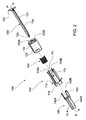
図1を参照すると、自動混合シリンジ10が、アクチュエート装置100、混合装置200、及び針アセンブリ300を含む。混合装置200は、デュアル同心の内側バレル210及び外側バレル220を有する。内側バレル210内には内側チャンバ230があり、外側バレル220と内側バレル210との間には外側チャンバ240がある。更に図2を参照すると、アクチュエート装置100の一実施形態の分解組立図が示されており、アクチュエート装置100は、ハウジング110と、ハウジング110にマウント可能なトリガ部材120とを含み、更に図3Aから図3Cを参照すると、組み立てられたアクチュエート装置100が示されている。ハウジング110は更に、開口111、フックアーム112A、112B、フランジ113、及びハウジングマウント114を含む。送達プランジャ130がシャフト131を含み、シャフト131はボタン132及び封止係合部材133を含む。送達プランジャ130は、後で詳述するように、開口、例えば、トリガ部材120の軸方向開口121、及びハウジング110の軸方向開口111を通り抜けて、軸方向に平行移動することが可能であるように構成されている。トリガ部材120は更に、内部チャンバ122及びロック/トリガスロット123A、123Bを含む。混合プランジャスリーブ140が、スリーブ部材141A、141B、プロング142A、142B、及びスリーブプラトー143を含む。この実施形態における付勢部材150はばねであり、このばねは、アクチュエート装置100が活性化される前の初期状態では圧縮されている(即ち、エネルギが蓄積されている)。図1を再度参照すると、当然のことながら、プランジャ130は混合装置200の内側チャンバ230内で軸方向の平行移動が可能であり、混合プランジャ140は混合装置200の外側チャンバ240内で軸方向の移動が可能であるが、これは、初期状態では、トリガ部材120の回転が行われるまで妨げられる。これについては後述する。図3Aから図3Cに示されるように、本発明の少なくとも1つの実施形態では、トリガ部材120の少なくとも一部分がアクチュエート装置100のハウジング110上にマウントされており、且つ、トリガ部材120はハウジング110とほぼ同心にマウントされており、これによって、トリガ部材120は、ハウジング110上で軸を中心に回転可能であり、且つ/又は、軸方向に平行移動可能である。図3A及び図3Cは、混合プランジャ140とトリガ部材120との間の解放可能なロック構成を示す。混合プランジャ140は、初期状態では、プロング142A、142Bと対応するトリガ部材スロット123A、123Bとの間の解放可能に係合可能な相互作用によって、トリガ部材120と係合されている。付勢部材150は、初期状態では、トリガ部材120と混合プランジャスリーブ140との間でエネルギ蓄積状態で保持されている。少なくとも1つの実施形態では、付勢部材150は、初期状態では、トリガ部材120の内部チャンバ122内で保持されており、混合プランジャ140のスリーブプラトー143にのしかかっている。
Referring to FIG. 1, an
トリガ部材120は回転可能(即ち、時計回り又は反時計回りに回転可能)であるが、図3Dによれば、ハウジング110内のリブ117A、117B、117C、117Dが混合プランジャ140内の相補形リッジ143A、143B、143C、143Dと係合することによって混合プランジャ140の回転が妨げられており、これによって、トリガ部材120が回転しても混合プランジャ140は回転しない。
The
更に図1を参照すると、スリーブ部材141A、141Bは、混合装置200の外側バレル220と内側バレル210との間の外側チャンバ240内にある近位封止材250とつながるか、当接するか、接触するように構成されている。混合装置200の外側バレル220と内側バレル210との間の外側チャンバ240内には遠位封止材260も配置されており、その機能については後で詳述する。混合装置200には更に、ベントキャップ270がマウントされている。この実施形態では、遠位封止材260は、内側バレル210のアパーチャ211A、211Bより近位に配置され、アパーチャ211A、211Bは、外側チャンバ240と内側チャンバ230との間の流体経路をそれぞれ形成する。ベントチャンバ280が遠位封止材260より遠位に位置する。後で詳述するように、アクチュエート装置100を操作及び運用することにより、外側チャンバ240に収容された第1の物質を、内側チャンバ230に収容された第2の物質と混合することが容易になる。混合された物質が、送達プランジャ130の軸方向平行移動によって、針アセンブリ300を通って注射されることにより、患者への薬剤送達が行われる。
Still referring to FIG. 1, the sleeve members 141 </ b> A, 141 </ b> B connect to, abut, or contact the
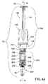
図4A及び図4Bは、図1及び図2に示された実施形態の側面図及び側面断面図を示しており、例えば保管時又は輸送時に利用可能な、初期状態のロックされた構成を示している。トリガ部材120の回転が行われるまで、プランジャ130は混合装置200の内側チャンバ230内で軸方向に平行移動できず、混合プランジャ140は混合装置200の外側チャンバ240内で軸方向に移動できない。これについては後述する。この状態では、剛体の針シールド15がカニューレ311を取り外し可能に覆っている。アクチュエート装置100は、自動混合シリンジ10の製造の為に、あらかじめ混合装置200と一緒に成形されてよく、或いは、アクチュエート装置100及び混合装置200は、接続されるか他の方法で一緒にマウントされる別々の構造体であってよい。後者の実施形態では、混合装置200は、アクチュエート装置100のハウジング110をその上に接続できるマウントを含んでよい。少なくとも1つの実施形態では、そのマウントは、混合装置200の外側バレル220の近位端Pに位置する。上述のように、アクチュエート装置100の混合プランジャ140は、少なくとも一部分が混合装置200の外側チャンバ240内にあって軸方向に平行移動するように構成されている。混合プランジャスリーブ140が軸方向に平行移動すると、近位封止材250が軸方向に平行移動し、これによって、流体が混合装置200の外側チャンバ240から内側チャンバ230に移動する。これについては本明細書で詳述する。スリーブ140は、トリガ部材120の動作によって軸方向に平行移動する。
4A and 4B show side and side cross-sectional views of the embodiment shown in FIGS. 1 and 2, showing an initial locked configuration that can be used, for example, during storage or transportation. Yes. Until the
図5A及び図5Bは、図1に示された実施形態の側面図及び側面断面図を示しており、トリガ部材120のロックが解除されてアクチュエート装置100が活性化された後の様子を示している。図示されるように、ユーザがトリガ部材120を時計回り又は反時計回りに回転させることにより、アクチュエート装置100を活性化させることが可能である。活性化されると、混合プランジャ140は、例えばプロング142A、142Bとトリガスロット123A、123Bとの間の係合が解除されることによって、トリガ部材120から外れ、付勢部材150がその初期のエネルギ蓄積状態から伸長することによって、遠位方向に軸方向平行移動する。混合プランジャ140がそのように軸方向に平行移動すると、スリーブ部材141A、141Bは、混合装置100の近位封止材250と接触し、近位封止材250を軸方向に平行移動させる。従って、アクチュエート装置100のプランジャ部材140が遠位方向に動くと、スリーブ部材141A、141Bが係合されているか当接している近位封止材250が動く。外側バレル220と内側バレル210との間の外側チャンバ240内であって、外側チャンバ240内の近位封止材250と遠位封止材260との間に、第1の混合物質が収容されてよい。遠位封止材260は、初期状態では、少なくとも一部分が、外側チャンバ230と内側チャンバ240との間の内側バレル210にある1つ以上のアパーチャ211A、211Bより上方(即ち、近位)の第1の位置にあってよい。混合プランジャ140及び近位封止材250の動きは、外側チャンバ240内の第1の混合物質に伝わり、同様に、遠位封止材260に伝わる。少なくとも1つの実施形態では、スリーブ140、近位封止材250、従って、外側チャンバ240内の第1の混合物質の動きは、近位封止材250の動きによって第1の混合物質内に発生する空気圧又は力によって遠位封止材260に伝わる。従って、混合プランジャ140の軸方向の動きは、遠位封止材260が第2の位置まで軸方向に動くことを間接的に(即ち、直接の接触を必要とせずに)推進する。遠位封止材260が第2の位置まで(即ち、図4Aのハッチング矢印の方向に)動くと、外側チャンバ240に収容されている第1の混合物質は、1つ以上のアパーチャ211A、211Bを通り抜けて内側バレル210の内側チャンバ230に入ることが可能である。
5A and 5B show a side view and a side cross-sectional view of the embodiment shown in FIG. 1, showing the state after the
実施形態によっては、ベントキャップ270は、基本的には、国際公開WO2013/020170又は国際公開WO2013/020170に記載されているとおりであってよい。ベントキャップ270の他の実施形態が図15A及び図15Bに示されており、ベントキャップ270は、任意選択で、混合装置100の動作中に遠位封止材260の所望の位置決めを容易にする、外側チャンバ240内に配置可能な「内部」ベントキャップ機能を有してよい。この「内部」ベントキャップ機能は、例えば、外側チャンバ240内の第1の物質のほぼ全量が内側チャンバに通り抜けることを可能にする為に、外側チャンバ240内での軸方向平行移動時に遠位封止材260を、1つ以上のアパーチャ211A、211Bに対して正しく位置決めするように構成された、ポスト、プロング、フレックスアームなどのような突起物であってよい。図6Aは、ベント271A、271B、271C、271D及びポスト272A、272B、272C、272Dを有するベントキャップ270の一実施形態を示しており、これらのベント及びポストは外側チャンバ240の内側で内向きに位置することになる。図6Bは、フレックスアーム273A、273B、273Cを有するベントキャップ270の一実施形態を示しており、これらのフレックスアームは外側チャンバ240の内側で内向きに位置することになる。外側チャンバ240と内側チャンバ230との間のアパーチャ211A、211Bは、第1の物質のほぼ全量が近位混合プランジャ封止材250によって外側チャンバ240から押し出されるまで、第1の物質が動くのを可能にする為に開いたままであることが望ましい。これは、近位封止材250自体の圧縮性によって達成可能である。追加又は代替として、外側チャンバ240内の第1の物質のほぼ全量が確実に内側チャンバ230へ通り抜けるように、内部ベントキャップ機能の寸法及び屈曲性は、遠位封止材250とアパーチャ211A、211Bとを位置合わせするように構成されてよい。従って、近位混合プランジャ封止材250が遠位封止材260と接触して、第1の物質のほぼ全量が、近位混合プランジャ封止材250によって外側チャンバ240から押し出されて内側チャンバ230に入るまで、アパーチャ211A、211Bが開いたままであるように遠位封止材260はアパーチャ211A、211Bに対して浮くか自己調節されることが可能にされている。
In some embodiments, the
当然のことながら、遠位封止材260とベントキャップ270との間のベントチャンバ280は、混合装置200内のいかなる物質とも接触することがない為、ベントチャンバ280内を無菌に保つことは不要である。ベントチャンバ280は空気が充填されてよく、この空気は、近位封止材250が押下され、遠位封止材260が軸方向に動くと、外側バレル220と内側バレル210との間、並びに、ベントキャップ270のベント271と遠位封止材260との間の環状空間から追い出される。更に、初期状態では遠位封止材260が内側バレル210のアパーチャ211A、211Bを覆っている為、混合装置200の使用中は、外側チャンバ240と内側チャンバ230との間のこの流体経路の無菌が維持される。外側バレル220及び内側バレル210の非無菌部分と接触する可能性があるのは遠位封止材260だけであり、これは、流体は非無菌部分と接触することなく外側チャンバ230から内側チャンバ230に流れ込むことになる為である。
Of course, the
又、当然のことながら、自動混合シリンジ10は「閉じたシステム」であり、これは、注射針による以外に流体経路のベントを行うことができないことを意味する。従って、送達プランジャ封止材160は、スリーブ140の遠位方向の動きに対する応答として、内側チャンバ230内を近位方向に軸方向移動することが可能である。これは、近位封止材250に対してスリーブ140が遠位方向に動くことによって、液体が外側チャンバ240から内側チャンバ230に流れ込むこととなり、内側チャンバ230内の圧力及び/又は流体体積が増える為である。剛体の針シールド15が針を覆って閉じたままの状態では、内側チャンバ230内で送達プランジャ封止材160を近位方向に動かす以外に体積拡大の余地はない。これは、混合が完了したこと、並びに注射を開始してよいことをユーザに視覚的且つ触覚的に示すものであり、望ましい応答である。
Of course, the self-mixing
上述のように、初期状態では、混合装置200の近位端、例えば、内側バレル210の近位端に、封止メンブレン290があってよく、これは、組み立てられて物質が充填された後であってアクチュエート装置100に接続される前に、バレル210、220の近位端を覆うためである。封止メンブレン290は、医療機器業界や製薬業界で使用されている様々な無菌ファブリック及び無菌材料のいずれか(例えばタイベック)であってよい。封止メンブレン290は、アクチュエート装置100の動作によって、又は操作中のシリンジユーザによって自動的に、取り外されるか、穴をあけられるか、他の方法でバイパスされてよい。図7に示される一実施形態によれば、スリーブ140は、外側チャンバ240内を軸方向に平行移動して、近位封止材250と接触し、これを移動させる。封止部材290は、図7に示されるように、内側バレル210の近位端を封止し、スリーブ部材141A、141Bの軸方向平行移動によって取り外されるように構成されている。この動作と並行して、前述のように、近位封止材250が混合装置200の外側バレル220の外側チャンバ240内を軸方向に摺動可能に動くことが可能であり、これによって、外側チャンバ240の内容物が、内側バレル210の1つ以上のアパーチャ211A、211Bを介して、内側チャンバ230に送達される。一代替実施形態では、封止メンブレン290は、円盤状であってよく、外側チャンバ240に延びたり、他の方法で一部分が外側チャンバ240内にあったりせずに内側チャンバ230内に位置してよく、混合プランジャ140が接触可能であってよい。この実施形態では、封止メンブレン290は、送達プランジャ130で穴をあけたり送達プランジャ130を突き刺したりすることが可能であり、混合プランジャ140とは接触しない。そのような機能の為に構成された送達プランジャ130が図9Eに示されており、これは、例えば、封止メンブレン290に穴をあけて送達プランジャ封止材160と係合する為の鋭い遠位先端を有する。
As mentioned above, in the initial state, there may be a sealing
トリガ部材120と混合プランジャ140との係合を解除する為にトリガ部材120を回転させている間は、トリガ部材120と接続されている送達プランジャ130も回転する。この接続によって、トリガ部材120を回転させたときにそれによって送達プランジャ130が軸回転し、送達プランジャ130がハウジング110からロック解除されたときにトリガ部材120内で送達プランジャ130が軸方向に摺動可能に移動することが可能になる。図8Aに示された、アクチュエート装置100の初期ロック状態においては、ハウジング110の当接部115A、115Bが送達プランジャ130に当接して、送達プランジャ130の軸方向移動を防ぐ。送達プランジャ130は、トリガ部材120を回転させると送達プランジャ130も回転するように、トリガ部材120と結合されている。この結合は、何らかの相補形嵌合部分を含んでよく、これによって、送達プランジャ130がトリガ部材120内を軸方向に摺動可能に動くことが可能になる。図8Bは、トリガ部材120を回転させて(即ち、時計回り又は反時計回りに回転させて)混合プランジャ140を活性化させたときに、この回転によって更に、送達プランジャ130のスロット134A、134Bがそれぞれ、ハウジング110の当接部115A、115Bと位置合わせされ、これによって、送達プランジャ130が軸方向に移動して混合物質を内側チャンバ230から受容者に送達することが可能になることを示している。当然のことながら、当接部115A、115Bが有する長手方向の形状によって、当接部115A、115Bはそれぞれ、送達プランジャ130のスロット134A、134Bに嵌め込まれ、摺動可能に係合することが可能である。
While the
一実施形態では、トリガ部材120が回転すると、1つ以上のトリガロック部材が1つ以上の相補形ハウジングロック部材と係合して、トリガ部材120の更なる回転を防ぐ。これは、トリガ部材120と混合プランジャスリーブ140との係合が解除された後のばね150の伸長の結果としてのトリガ部材120の近位方向の動きによって促進されてよい。図8Cに示される一特定実施形態では、ハウジングロック部材は、ロックチャネル116である。適切なことには、1つ以上のトリガロック部材126が、ハウジング110内で1つ以上の相補形ロックチャネル116と係合して、トリガ部材120の更なる回転を防ぐ。ロックチャネル116は、ロック状態では、トリガ部材120の軸回転及び/又はトリガ部材120の軸方向平行移動を防ぐように構成されている。
In one embodiment, as the
送達プランジャ130は送達プランジャ封止材160にマウントされており、送達プランジャ封止材160は、混合装置200の内側バレル110の内側チャンバ230内で軸方向に摺動可能に可動であり、これによって、内側チャンバ230の混合された内容物が送達される。送達プランジャ130の、送達プランジャ封止材160との結合は、図10A及び図10Bに示されるように、相補形ねじ133及び161のねじ込み係合によって行われてよく、或いは、図9Eに示されるような、別の形式の接触係合によって行われてよい。この段階では、自動混合シリンジ10は、その混合された物質を送達する準備が整っている。剛体の針シールド15が取り外され、引き込み式針310のカニューレ311が受容者に挿入され、送達プランジャ130が押下されて、内側チャンバ230の混合された流体内容物が受容者に送達される。標準的な医療行為、例えば、物質の混合を更に促進する為に自動混合シリンジ10を手動で攪拌すること、及び/又は、残留している空気を注射前に全て除去する為にシリンジに呼び水を差すことが、針挿入及び流体内容物の注射の前に行われてよい。本明細書に記載の、一体化されたプランジャ130を有するアクチュエート装置100は、自動混合シリンジ10のうちのそれ以外の部分とは別個に組み立てられてよい。これが望ましいと考えられるのは、例えば、製薬会社が、シリンジ10への薬剤物質の充填を自社の標準的な充填仕上げラインで実施し、そのような充填済み構成要素を封止して、最終組み立ての為に別の会社に出荷したい場合である。更に、これは、出荷、輸送、又は他の幾つかの理由で望ましい場合がある。更に、複数の構成要素を別々に安全且つ効率的に廃棄する為に、アクチュエート装置100を、自動混合シリンジ10の混合装置200とは別の構成要素として有することが望ましい場合がある(即ち、使用して汚染された部分だけを安全鋭利物容器に廃棄する必要があり、それ以外の構成要素は別個に廃棄してよい)。
The
本発明の少なくとも1つの実施形態では、アクチュエート装置100は、針引き込み機構を有する自動混合シリンジ10とともに利用される。
In at least one embodiment of the present invention, the
好ましい一針引き込み機構は、針引き込みを促進する1つ以上の付勢部材を含む針アセンブリ300を含む。図9Aから図9Eに示されるように、後述される一実施形態とは異なり、針アセンブリ300は、送達プランジャ130によってアクチュエート可能な1つ以上の付勢部材340を含み、送達プランジャ封止材160と引き込み式針310は係合しておらず、針アセンブリ300の付勢部材340が解放されると、引き込み式針310の引き込みが引き起こされる。図9A及び図9Bに示された実施形態は、針アセンブリ300において単一の付勢部材340(例えば、単一のばね)を有し、図9Cから図9Eに示された実施形態は、ばね342、344を含む付勢部材340を有する。
A preferred single needle retraction mechanism includes a
図9A及び図9Bは、本発明の一実施形態による断面図を示す。針アセンブリ300は、引き込み式針310を含み、引き込み式針310は、オーバーモールド型針(「NOM」)322と、カニューレ311と、任意選択で、引き込み後にカニューレ311をブロックするように適応された針ブロック機構と、を含む。図示された実施形態では、針ブロック機構はクリップ324を含む。クリップ324は、初期状態では、摺動可能又は取り外し可能にNOM322と係合してよく、これは、例えば、クリップアーム324AとNOM係合面322Aとの間の係合において行われてよい。カニューレ301が引き込まれ、NOM322が近位方向に軸方向平行移動すると、クリップアーム324Aは、内向きに(即ち、軸Aに向かって)曲がって、針ブロック構成内のNOM先端322Dと接触することが可能である。そのような針ブロック構成は、引き込み後の遠位方向の軸方向移動を防ぎ、カニューレ311をほぼバレル先端330内且つ/又はシリンジ10のバレル内に保持する。
9A and 9B show cross-sectional views according to one embodiment of the present invention.
図9Aを参照すると、針アセンブリ300は更に、アクチュエータサブアセンブリによってアクチュエートされてカニューレ311が引き込まれるまで付勢部材340をエネルギ蓄積位置に保持するように配置されたアクチュエート可能なロック構成を含む。図示された実施形態では、バレル先端330は、ばねガイド330Aを含む。付勢部材340をその初期エネルギ蓄積位置に保持する為に、NOM322は、初期状態では、バレル先端330と係合して配置されて、エネルギ蓄積状態の付勢部材340を、NOM322の1つ以上のレッジ322Cと、バレル先端330の係合面330Cとで挟んでよい。アクチュエート可能なロック構成のそのような一実施形態では、バレル先端330のばねガイド330Aは、例えばNOM122のロックプロング322Bを受けるように適応された、1つ以上のロック凹部又はロックレッジ330Bを含んでよい。後で詳述するように、流体経路、即ち、針310からの薬剤送達がほぼ完了したら、アクチュエート可能なロック構成は、ロックプロング322Bを内向きに動かしてバレル先端330のロック凹部330Bから解放するように、アクチュエータサブアセンブリによってアクチュエートされてよく、それによって、付勢部材340のエネルギが放出されて、NOM322のレッジ322Cに力が作用して針310が引き込まれることが可能になる。
Referring to FIG. 9A,
アクチュエータサブアセンブリ370は、アクチュエート可能なロック構成をアクチュエートして、付勢部材340がエネルギを放出して針310を引き込むことを可能にするように配置される。図示された実施形態では、アクチュエータサブアセンブリ370は、針封止材316、押し棒312、及びアクチュエータ314を含む。実施形態によっては、押し棒312は、針封止材316に対して摺動可能に配置される。少なくとも1つの実施形態では、押し棒312は、少なくとも一部分が針封止材316の近位端内にあって、針封止材316より遠位にあるアクチュエータ314と接触している。そのような構成において押し棒を押下することにより、アクチュエータ314と接触し、アクチュエータ314を押下する(又は遠位方向に軸方向平行移動させる)ことが可能である。例えばユーザの身体に針を挿入する為の、少なくとも一初期構成では、アクチュエータサブアセンブリ310は、針サブアセンブリ320より近位にあってよく、針サブアセンブリ320と接触しているか近接していてよい。
少なくとも1つの実施形態では、押し棒312は、近位接触面312A及び1つ以上の力伝達要素312Bを含み、これらの力伝達要素312Bは、針封止材316内の対応する貫通路316Bを通って延びる。組み立て時には、針封止材316を貫通して延びる力伝達要素312Bは、押し棒312が軸方向に動くとアクチュエータ314が軸方向に動くように、アクチュエータ314と係合する。この点において、押し棒312及びアクチュエータ314は、組立工程中に係合及び結合されてよく、或いは、これらの構成要素は、押し棒312がアクチュエータ314と係合してアクチュエータ314を軸方向に動かす前に、押し棒312を多少軸方向に動かすことが可能であるように、そのような組み立てにおいて配置されてよい。なお、針封止材316は更に、カニューレ311の近位端が貫通して延びて薬剤送達用経路を確立する開口316Aを含んでよい。
In at least one embodiment,
アクチュエータ314は、アクチュエート可能なロック構成と係合してこれをアクチュエートすることにより針引き込み機構311をアクチュエートするように配置された1つ以上のアクチュエート面314Aを含む。動作を容易にする為に、図示された実施形態では、アクチュエート面314Aは傾斜が付いており、NOM322のロックプロング322Bの対応する傾斜が付いた面322Eと係合するように配置される。このように、アクチュエータ314が軸方向に動くと、アクチュエート面314Aがロックプロング322Bの傾斜が付いた面322Eに沿って摺動して、ロックプロング322Bを半径方向内向きに押し、これによってロックプロング322Bがバレル先端330のロック凹部330Bから係合解除される。その結果、付勢部材340は、少なくとも一部のエネルギを放出してカニューレ311を引き込むことが可能になる。
言い換えると、動作中、送達プランジャ封止材160(図示せず)は、押し棒312との接触を引き起こされる。その結果、薬剤送達中にプランジャ封止材160が更に押下されると、押し棒312が遠位方向に軸方向平行移動して、少なくとも一部分が針封止材316を貫通するか、或いは更に多くの部分が貫通する。押し棒312がアクチュエータ314と接触していると、押し棒312が軸方向に平行移動することにより、アクチュエータ314も軸方向に平行移動する。アクチュエータ314が軸方向に平行移動すると、NOM122のロックプロング322Bと接触し、ロックプロング322Bが曲がって、ロックプロング322Bが、ばねガイド330Aの対応するロック凹部330Bから係合解除される。
In other words, during operation, the delivery plunger seal 160 (not shown) is caused to contact the
ロックプロング322B間のロック構成が、対応するロック凹部330Bから係合解除されると、付勢部材340は、その初期エネルギ蓄積状態からエネルギ低減状態又はエネルギ放出状態へと近位方向に伸長することが可能になる。この、付勢部材340の近位方向の伸長によってNOM322のレッジ322Cが押され、これによって、NOM322及びカニューレ311が近位方向に平行移動して引き込まれた状態になる。上述のように、針101が引き込まれ、NOM322が近位方向に軸方向平行移動すると、クリップアーム324Aは、内向きに(即ち、軸Aに向かって)曲がって、針ブロック構成内のNOM先端322Dと接触することが可能である。そのような針ブロック構成は、引き込み後の遠位方向の軸方向移動を防ぎ、針310をほぼバレル先端330内且つ/又はシリンジのバレル内に保持する。本発明の少なくとも1つの実施形態では、押し棒312及びアクチュエータ314は、一体型又は単一の構成要素である。
When the locking configuration between the locking
図9Cから図9Eを参照すると、針アセンブリ300の別の実施形態が示されており、これは、バレル先端330、針サブアセンブリ320、針引き込みサブアセンブリ360、及びアクチュエータサブアセンブリ370を含む。針サブアセンブリ320は、カニューレ311及びオーバーモールド型針(NOM)322を含む。アクチュエータサブアセンブリ370は、針封止材316及び押し棒312を含む。針サブアセンブリ320は、針封止材316と係合されており、カニューレ311の近位端が針封止材316の開口316Aを貫通して延びる。NOM322は、任意の適切な方式で針封止材316と確実に結合されてよい。例えば、図示された実施形態では、NOM322は、複数のフランジを含み、第1のそのようなフランジ322Fが針封止材316の内部フランジ316Cと係合し、第2のそのようなフランジ322Gが針封止材316の下面に沿って配置される。NOMの更なる特徴については、針引き込みサブアセンブリ360とアクチュエータサブアセンブリ370との関係に関して後述する。
Referring to FIGS. 9C-9E, another embodiment of a
押し棒312は、近位接触面312Aと、少なくとも1つの従属力伝達要素312Bと、を含む。ここで、一対の力伝達要素312Bが、針封止材316内の貫通路を通って延びる。組み立て時には、近位接触面312Aは、針封止材316の近位側に配置される。しかしながら、図9A及び図9Bの実施形態とは異なり、押し棒312の力伝達要素312Bは、アクチュエート面312Cを含み、これは、ここでは角度が付いた面である。言い換えると、この実施形態は、独立したアクチュエータを含まない。代わりに、押し棒312とアクチュエータは一体型の構成要素である。
The
針引き込みサブアセンブリ360は、少なくとも1つの付勢部材340と、アクチュエート可能なロック構成と、を含む。この実施形態では、付勢部材340は、一対のばね342、344を含む。ばね342、344は平行に配置されていて、これらのばねが同時にエネルギ放出位置に向かって動くように支持構造が与えられているが、代替として、ばね342、344は、これらのばねが順次、エネルギ放出位置に向かって動くように配置及び支持されてよい。配置が直列であっても並列であっても、2つ以上のばねを含むことにより、バレルアダプタ350の全体パッケージサイズを低減することにおいて一定の利点を提供しうる。ただし、当然のことながら、並列のばね342、344を支持することは、これらの利点を更に強化しうる。
Needle retract
この実施形態では、バレル先端330は、複数の構成要素を含む。即ち、ばねガイド330Aは、先端部分330Dとは別個に成形され、ばねガイド330Aと先端部分330Dは組み立て時に結合される。付勢部材340、即ち、ばね342、344は、ばねガイド330Aの周辺部で受けてよい。針サブアセンブリ320及びアクチュエータサブアセンブリ310のアセンブリをばねガイド330Aに挿入すると、針サブアセンブリ320とばねガイド330Aは結合されて、付勢部材340を、係合面330Cとレッジ322Cとの間のエネルギ蓄積位置で保持することが可能である。第1の実施形態とは異なり、この実施形態では、ばねガイド330Aは、少なくとも1つのロックプロング330B、ここでは一対のロックプロング330Bを含み、NOM322は、ロックレッジ322Bを含む。従って、当然のことながら、薬剤投与の最終時点で押し棒312にプランジャ封止材160(図示せず)が接触すると、押し棒312のアクチュエート面312Cは、ばねガイド330Aのロックプロング330Bを外向きに押して、それらをNOM322のロックレッジ322Bから係合解除する。その結果、付勢部材340は、図9Eに示されるように、エネルギを放出して針サブアセンブリ320をバレル内に引き込むことが可能になる。そのような実施形態では、トリガ部材120が近位方向に実質的に動かなくても針サブアセンブリ320の引き込みが可能になる。これは、押し棒312が、内側バレル210内への針サブアセンブリの直接の引き込みを活性化する為である。
In this embodiment,
一代替実施形態では、引き込み式針310は、送達プランジャ封止材160との係合によって引き込まれ、それによって、アクチュエート装置100の付勢部材150は、引き込み式針310の引き込みを促進する。図10A及び図10Bに示される特定実施形態では、送達プランジャ130は、シャフト131及び封止係合部材133を含み、封止係合部材133は、この実施形態ではねじ込み凸部であり、これは、送達プランジャ封止材160の相補形ねじ込み凹部161と係合する。この、引き込み式針310が送達プランジャ封止材160との係合によって引き込まれる実施形態では、送達プランジャ封止材160は更に、針係合部又は凹部162を含む。少なくとも1つの実施形態では、針アセンブリ300は引き込み式針310を含み、引き込み式針310は、カニューレ311及び針ボディ394と、アーム391A、391B及びフック端部392A、392Bを有する保持部391と、針封止材393と、イジェクタリング396を有するイジェクタ395と、を含む。図10A及び図10Bに示された針引き込み機構は、本質的には、WO2011/075760に記載のものと同様である。流体内容物の送達中、送達プランジャ130及び結合された送達プランジャ封止材160は、内側チャンバ230内を、図10Aから図10Cのハッチング矢印の方向に軸方向移動する。送達プランジャ封止材160は針封止材314と当接し、針封止材314はイジェクタ395と当接する。これに加えて、イジェクタリング396は、保持部391のアーム391A、391Bのフック端部392A、392Bを、図10Aの塗りつぶし矢印の方向に半径方向外向きに動かし、これによって、針ボディ394が保持部390から係合解除されて引き込み式針310が解放され、その後、引き込まれる。この時点では、送達プランジャ封止材160の針係合部又は凹部162は、引き込み式針ボディ394と係合しており、カニューレ311の流体端部3111を受けている。これにより、引き込み式針310は、送達プランジャ封止材160及び送達プランジャ130と実質的に結合される。
In one alternative embodiment, the
図10Bに示されるように、流体内容物の送達終了時に引き込み式針310を引き込む為に、付勢部材150は、その部分的エネルギ蓄積状態又はエネルギ低減状態からエネルギを放出しなければならない。上述のように、付勢部材150は、初期状態では、スリーブ140を押下して(即ち、遠位方向に軸方向平行移動させて)第1の物質と第2の物質の混合を促進することに利用される。本明細書及びWO2011/075760に記載のように引き込み式針310を捕捉するなどして引き込み機構が適切に活性化されたら、付勢部材150は、引き込み式針310を引き込む(近位方向に軸方向平行移動させる)ことに利用されてもよい。初期状態では、図11Cに示されるように、トリガ部材120は、トリガ部材120の対応する保持スロット125A、125Bと係合するハウジングプロング112A、112Bによって解放可能に係合されて保持される。薬剤送達の終了時に、これらの構成要素の係合解除が、プランジャ130及び/又はボタン131の近位端によって促進される。流体を内側チャンバ230から注射する為にプランジャ130及び/又はボタン131がほぼ完全に押下されると(即ち、遠位方向に軸方向平行移動すると)、プランジャ130及び/又はボタン131の一方又は両方がハウジングプロング112A、112Bと接触することが可能である。この接触を通して、ハウジングプロング112A、112Bは、塗りつぶし矢印の方向に半径方向に動かされて、トリガ部材120の対応する保持スロット125A、125Bとの係合から外れる。この係合解除によって、不完全に圧縮されていた付勢部材150が更に減圧されてトリガ部材120を押すことが可能になり、これによって、プランジャ130が押されて引き込まれる。引き込み式針310に結合されている送達プランジャ封止材160は、付勢部材150の減圧によって、近位方向に軸方向平行移動して、図10Bに示されるように、引き込み式針310を引き込む。トリガ部材120は、近位方向に軸方向平行移動して、送達プランジャ130、送達プランジャ封止材160、及びこれに接続されていた引き込み式針310を引き込むことになる。図10Bに示されるように、保持部390、イジェクタ395、及び針封止材393は、内側チャンバ230の遠位端にとどまる。図10Dに示されるように、トリガ部材120、プランジャ130、送達プランジャ封止材160、及び引き込み式針310の引き込みの終了時に、トリガ部材120及び送達プランジャ130(並びにこれに接続されている関連構成要素)は、トリガ部材120の1つ以上のロックレッジ127、及びハウジング110の1つ以上のそれぞれのスナップアーム118によってロックアウトされてよい。針が混合装置のバレル内に引き込まれることに加えて、このロックアウトによって、自動混合シリンジ10の再使用又は不正使用が防がれ、自動混合シリンジ10が安全に廃棄されるようになる。同じく図10Dに示されるように、トリガ部材120の1つ以上のロックレッジ127と、ハウジング110の1つ以上のそれぞれのタブ119との間の相互作用によって、ハウジング110に対して相対的な、トリガ部材の軸方向移動が制限され、これによって、トリガ部材120とハウジング110との意図されない結合解除が防がれる。
As shown in FIG. 10B, in order to retract the
本発明の自動混合シリンジ10は、任意選択のカバーを有してよく、このカバーは、シリンジの混合段階の動作が正常に行われた場合のみ、自動的に係合解除されて除去される。図11A及び図11Bは、遠位カバー16を有する一実施形態を示す。図11A及び図11Bに示されるように、遠位カバー16は1つ以上のフレキシブルな逆棘アーム161を含み、混合プランジャ140の、塗りつぶし矢印で示された方向の軸方向移動の結果として混合段階が正常に終了した場合のみ、逆棘アーム161がハウジング110から係合解除されてよく、これによって、遠位カバー16の除去が可能になる。そのようなカバーは、混合シリンジの不注意な操作を防ぐ為に、安全キャップ及び/又は剛体の針シールドと一体であるか、これとともに動作してよい。図12A及び図12Bは、混合シリンジの別の実施形態を示しており、これはスタンドアロンのカラー式安全キャップ17を有する。物質の混合中に遠位封止材260が塗りつぶし矢印の方向に変位すると、遠位封止材260は、カラー式安全キャップ17に当接して、これを係合解除することにより、混合終了時の針シールド15の除去が可能になる。本明細書に開示の実施形態では、混合段階が正常に終了した場合に限り、安全キャップ16、17が除去可能であって、それによって、剛体の針シールド15を除去してカニューレ311を注射の為に露出することが可能になるように、安全キャップ16、17を構成することが可能である。
The
図13に示される少なくとも1つの実施形態では、自動混合シリンジ10は、遠位カバー18及び近位カバー19を含んでよい。そのようなカバーは、既知の様々な形状及び構成をとってよく、例えば、円錐形、円筒形、矩形などであってよい。この実施形態は、凍結乾燥させたインシュリン又はグルカゴンのような、血糖を調整する物質を迅速又は緊急に混合して送達する場合に特に有用又は適用可能であろう。この実施形態では、近位カバー18を回すかねじると、トリガ部材120が協調的に回転して、上述の物質の混合を活性化させるように、近位カバー18がトリガ部材120と結合されている。その後、遠位カバー19を取り外すと、少なくとも1つの実施形態では、剛体の針シールド15が「自動的に」外れることが可能であり、それによってカニューレ311が露出して使用可能になるように、遠位カバー19が剛体の針シールド15と結合されている。その後、近位カバー18を取り外して、送達プランジャ130を操作することにより、混合物質を注射によって受容者に送達することを可能にすることができる。この実施形態は、典型的には糖尿病によって発生するような緊急時に使える、非常に迅速で安全で操作が簡単な混合送達システムを提供する。そのような実施形態では、カバー18、19は、自動混合シリンジ10の全体パッケージング及び機能面の両方としての役割を果たす。
In at least one embodiment shown in FIG. 13, the self-mixing
上述の内容から理解されるように、本明細書に開示のアクチュエート装置、自動混合装置、及び自動混合シリンジは、複数の物質をシリンジによって送達する前に混合する為の、効率的で操作が簡単な自動システムを提供する。既に説明されたもののような多くの先行技術の混合装置と異なり、複数の流体経路を開いたり位置合わせしたりする為に内側バレル及び外側バレルを使用前に回転させたり、別の方法で方向づけたりする必要はない。外側バレルのベント、及び内側バレルのアパーチャに対する遠位封止材の相対的位置決めにより、適切な通気が行われる一方で混合装置の内容物が無菌に保たれ、この点は、既に説明されたような多くの先行技術の混合装置と異なる。 As can be appreciated from the foregoing, the actuating devices, self-mixing devices, and self-mixing syringes disclosed herein are efficient and easy to operate for mixing multiple substances prior to delivery by the syringe. Provide a simple automated system. Unlike many prior art mixing devices, such as those already described, the inner and outer barrels may be rotated before use or otherwise oriented to open and align multiple fluid paths. do not have to. The relative positioning of the distal seal relative to the outer barrel vent and the inner barrel aperture ensures proper venting while keeping the contents of the mixing device sterile, as has already been described. Unlike many prior art mixing devices.
アクチュエート装置、自動混合装置、引き込み式シリンジ、又はどの個別構成要素の組み立て及び/又は製造においても、当該技術分野における様々な既知の材料及び方法を利用してよい。例えば、構成要素及び/又は装置の洗浄には、イソプロピルアルコールやヘキサンなど、様々な既知の洗浄液を使用してよい。製造工程では、様々な既知の接着剤又は粘着剤を同様に使用してよい。更に、新規な構成要素及び装置の製造時には、既知のシリコン処理液及び処理工程を用いてよい。内側バレルに1つ以上のアパーチャを追加する際には、機械式穿孔やレーザ穿孔などの既知の穿孔方法や穴あけ方法を用いてよい。更に、最終製品を確実に無菌化する為に、1つ以上の製造段階又は組立段階において、既知の滅菌処理を用いてよい。 Various known materials and methods in the art may be utilized in the assembly and / or manufacture of actuating devices, automatic mixing devices, retractable syringes, or any individual component. For example, various known cleaning liquids such as isopropyl alcohol and hexane may be used to clean components and / or equipment. In the manufacturing process, various known adhesives or adhesives may be used as well. Furthermore, known silicon processing liquids and processing steps may be used when manufacturing new components and devices. When adding one or more apertures to the inner barrel, known drilling methods or drilling methods such as mechanical drilling or laser drilling may be used. In addition, known sterilization processes may be used in one or more manufacturing or assembly stages to ensure sterilization of the final product.
更に別の態様では、本発明は、自動混合装置を含むシリンジの組立方法を提供し、この方法は、シリンジの混合装置にアクチュエート装置を取り外し可能にマウントするステップを含み、このマウントは、アクチュエート装置のスリーブが混合装置の混合プランジャ封止材を押下するように動作可能であるように行われる。一実施形態では、本方法は、アクチュエート装置のハウジングを混合装置の外側バレルに解放可能に接続又は結合するステップを含む。一実施形態では、本方法は、アクチュエート装置のハウジングを混合装置の外側バレルに解放可能に接続又は結合するステップを含む。一実施形態では、本方法は更に、ステップ(i)の前に、内側バレルの、1つ以上のアパーチャより遠位に位置する部分に、1つ以上のベントを含むベントキャップを取り付けるステップを含む。好ましくは、外側バレルの遠位端は、ベントキャップに接続される。更なる一実施形態では、本方法は更に、混合装置にアクチュエート装置を取り付ける前に、混合装置の内側バレルの近位端に封止メンブレンを取り付けるステップを含む。好ましい一実施形態では、封止メンブレンは、その少なくとも一部分が送達プランジャの動作によって穴をあけられるか貫通されるように取り付けられる。別の実施形態では、封止メンブレンは、アクチュエート装置のスリーブの動作、即ち、スリーブの遠位方向の軸方向平行移動によって自動的に取り外されるように取り付けられる。好ましくは、本方法は更に、1つ以上のアパーチャより遠位に位置する内側チャンバに針アセンブリを挿入するステップを含む。 In yet another aspect, the present invention provides a method for assembling a syringe including an automatic mixing device, the method comprising removably mounting an actuating device on the mixing device of the syringe, the mount comprising an actuator The sleeve of the eight device is operable to depress the mixing plunger seal of the mixing device. In one embodiment, the method includes releasably connecting or coupling the actuator device housing to the outer barrel of the mixing device. In one embodiment, the method includes releasably connecting or coupling the actuator device housing to the outer barrel of the mixing device. In one embodiment, the method further includes attaching a vent cap including one or more vents to a portion of the inner barrel that is distal to the one or more apertures prior to step (i). . Preferably, the distal end of the outer barrel is connected to the vent cap. In a further embodiment, the method further includes attaching a sealing membrane to the proximal end of the inner barrel of the mixing device prior to attaching the actuating device to the mixing device. In a preferred embodiment, the sealing membrane is attached such that at least a portion thereof is pierced or penetrated by the action of the delivery plunger. In another embodiment, the sealing membrane is attached such that it is automatically removed by movement of the actuating device sleeve, ie, distal axial translation of the sleeve. Preferably, the method further includes the step of inserting the needle assembly into an inner chamber located distal to the one or more apertures.
更なる一態様では、本発明は、シリンジの製造方法を提供し、本方法は、シリンジにマウントされた混合装置にアクチュエート装置を取り外し可能にマウントするステップを含む。 In a further aspect, the present invention provides a method for manufacturing a syringe, the method comprising removably mounting an actuating device on a mixing device mounted on the syringe.
更なる一態様では、本発明は、自動混合装置を含むシリンジの操作方法を提供し、前記方法は、
(i)複数の物質の混合を促進するように自動混合装置のアクチュエート装置を操作するステップであって、アクチュエート装置の操作によって、混合装置に取り付けられた取り外し可能なメンブレンが取り外される、アクチュエート装置を操作するステップと、
(ii)混合装置の送達プランジャ封止材にアクチュエート装置のプランジャを接続するステップと、
(iii)ステップ(i)で混合された物質を受容者に送達するようにプランジャを操作するステップと、を含む。
In a further aspect, the present invention provides a method of operating a syringe comprising an automatic mixing device, the method comprising:
(I) operating the actuating device of the automatic mixing device to facilitate mixing of a plurality of substances, wherein the actuating device removes a removable membrane attached to the mixing device; Operating the device;
(Ii) connecting the actuator plunger to the delivery plunger seal of the mixing device;
(Iii) manipulating the plunger to deliver the substance mixed in step (i) to the recipient.
一実施形態では、本方法は、ステップ(iii)の前にプランジャをロック解除するステップを含む。プランジャのロック解除は、本発明の少なくとも1つの実施形態ではステップ(i)とステップ(ii)の間の行われてよく、本発明の他の実施形態ではステップ(ii)とステップ(iii)の間の行われてよい。 In one embodiment, the method includes unlocking the plunger prior to step (iii). The unlocking of the plunger may occur between step (i) and step (ii) in at least one embodiment of the invention, and in steps of (ii) and (iii) in other embodiments of the invention. May be done between.
一代替実施形態では、自動混合装置を含むシリンジの操作方法は、
(iv)複数の物質の混合を促進するように自動混合装置のアクチュエート装置を操作するステップと、
(v)封止メンブレンに穴をあけて混合装置の送達プランジャ封止材と係合するようにアクチュエート装置のプランジャを操作するステップと、
(vi)ステップ(i)で混合された物質を受容者に送達するようにプランジャを操作するステップと、を含む。
In one alternative embodiment, a method of operating a syringe that includes an automatic mixing device comprises:
(Iv) operating an actuating device of the automatic mixing device to facilitate mixing of the plurality of substances;
(V) manipulating the plunger of the actuating device to puncture the sealing membrane to engage the delivery plunger sealant of the mixing device;
(Vi) manipulating the plunger to deliver the substance mixed in step (i) to the recipient.
本方法は更に、ステップ(iii)の前にプランジャをロック解除するステップを含んでよい。プランジャのロック解除は、本発明の少なくとも1つの実施形態ではステップ(i)とステップ(ii)の間に行われてよく、本発明の他の実施形態ではステップ(ii)とステップ(iii)の間に行われてよい。 The method may further include unlocking the plunger prior to step (iii). The unlocking of the plunger may occur between step (i) and step (ii) in at least one embodiment of the present invention, and in steps of (ii) and (iii) in other embodiments of the present invention. It may be done in between.
少なくとも1つの実施形態では、自動混合装置を含むシリンジの操作方法は更に、(iv)針をシリンジ内に引き込む為に針引き込み機構を活性化させるステップを含む。好ましくは、針引き込み機構の活性化は、物質のほぼ全量が受容者に送達された後に行われる。 In at least one embodiment, the method of operating a syringe including the automatic mixing device further includes (iv) activating a needle retraction mechanism to retract the needle into the syringe. Preferably, the activation of the needle retraction mechanism occurs after approximately the entire amount of substance has been delivered to the recipient.
上述のように、本発明の幾つかの態様が、別々の構成要素によって推進されてよい。或いは、本発明の1つ以上の構成要素が、一体型構成要素であってよく、且つ/又は、そのような1つ以上の構成要素の機能が一体型構成要素によって達成されてよい。例えば、トリガ部材、及び幾つかの他の構成要素は、単一の一体型構成要素であってよく、或いは、複数のより小さな副構成要素で構成されてよい(例えば、トリガ部材の内面、具体的にはトリガ部材の内部近位端にある構成要素は、互いにスナップ係合されるか他の方法で1つの構成要素として機能する複数の副構成要素であってよい)。当業者であれば容易に理解されるように、そのような構成要素は、特許請求される本発明の広さ及び範囲を逸脱しない限り、例えば製造しやすさの為に、一体型構成要素であってよく、複数の別々の副構成要素で構成されてもよい。 As mentioned above, some aspects of the invention may be driven by separate components. Alternatively, one or more components of the present invention may be an integral component and / or the function of one or more such components may be achieved by an integral component. For example, the trigger member and several other components may be a single integrated component or may be composed of multiple smaller subcomponents (eg, the inner surface of the trigger member, in particular In particular, the component at the inner proximal end of the trigger member may be a plurality of sub-components that snap together or otherwise function as one component). As will be readily appreciated by those skilled in the art, such components may be integrated components, for example for ease of manufacture, without departing from the breadth and scope of the claimed invention. There may be a plurality of separate sub-components.
シリンジ製造工程の充填ステップを達成する為に、様々な既知の充填処理及び充填機器が利用されてよい。一実施形態では、第2の流体物質は、液体物質として充填されてよく、特定のバレル伝熱機器を用いて現場で凍結乾燥されてよい。これらの製造工程及び組立工程において記述された針アセンブリ、送達プランジャ、及び他の構成要素は、上述のとおりであってよく、或いは、それらの構成要素と同じ機能性を達成する幾つかの同様の構成要素であってよい。 Various known filling processes and filling equipment may be utilized to accomplish the filling step of the syringe manufacturing process. In one embodiment, the second fluid material may be filled as a liquid material and may be lyophilized in situ using specific barrel heat transfer equipment. The needle assembly, delivery plunger, and other components described in these manufacturing and assembly processes may be as described above, or some similar one that achieves the same functionality as those components. It may be a component.
本明細書を通してのねらいは、本発明をいかなる1つの実施形態又は特定の機能集合体にも限定することなく、本発明の好ましい実施形態を記述することであった。記述及び図示された実施形態に対しては、本発明から逸脱しない限り、様々な変更や修正が行われてよい。 Throughout the specification, the aim has been to describe the preferred embodiments of the invention without limiting the invention to any one embodiment or specific feature set. Various changes and modifications may be made to the described and illustrated embodiments without departing from the invention.
本明細書において参照されている特許文書、科学文書、コンピュータプログラム、及びアルゴリズムのそれぞれの開示は、参照によってその全内容が組み込まれている。
〔付記1〕
シリンジ(10)用混合装置(200)に取り外し可能にマウント可能なアクチュエート装置(100)であって、前記混合装置は1つ又は複数の封止材(250、260)を備え、前記アクチュエート装置は、前記混合装置(200)に解放可能に接続可能なハウジング(110)と、回転可能なトリガ部材(120)と、付勢部材(150)と、送達プランジャ(130)と、初期ロック状態では前記トリガ部材(120)と解放可能に係合されていて、前記混合装置(200)の前記1つ又は複数の封止材(250、260)のうちの少なくとも1つと係合可能である混合プランジャ(140)と、を備え、前記回転可能なトリガ部材(120)は、前記1つ又は複数の封止材(250、260)と係合された場合に、前記付勢部材(150)が前記混合プランジャ(140)の押下を促進することを開始するように動作可能である、アクチュエート装置。
〔付記2〕
前記トリガ部材(120)を回転させると、前記混合プランジャ(140)が前記トリガ部材(120)から係合解除されて、前記付勢部材(150)が、前記1つ又は複数の封止材(250、260)のうちの前記少なくとも1つと係合された場合に、前記混合プランジャ(140)の押下を促進することが開始され、これによって、前記混合装置(200)内の前記複数の物質が混合される、付記1に記載のアクチュエート装置。
〔付記3〕
前記混合プランジャ(140)は1つ又は複数のプロング(142A、142B)を備える、付記1又は2に記載のアクチュエート装置。
〔付記4〕
前記トリガ部材(120)は、1つ又は複数のスロット部材(123A、123B)を備える、付記1から3のいずれか一項に記載のアクチュエート装置。
〔付記5〕
前記初期ロック状態では、前記1つ又は複数のプロング(142A、142B)は、初期状態では前記スロット部材(123A、123B)と係合していて、前記スロット部材(123A、123B)との係合から外れて回転することが可能であり、これによって、前記付勢部材(150)が、前記1つ又は複数の封止材(250、260)のうちの前記少なくとも1つと係合された場合に、前記混合プランジャ(140)の押下を促進することが開始され、これによって、前記混合装置(200)内の前記複数の物質が混合される、付記3又は4に記載のアクチュエート装置。
〔付記6〕
前記ハウジング(110)は、1つ又は複数の当接部(115A、115B)を備える、付記1から5のいずれか一項に記載のアクチュエート装置。
〔付記7〕
前記送達プランジャ(130)は、1つ又は複数のチャネル(134A、134B)を備える、付記1から6のいずれか一項に記載のアクチュエート装置。
〔付記8〕
前記初期ロック状態では、前記1つ又は複数の当接部(115A、115B)は、前記チャネル(134A、134B)と位置合わせされておらず、これによって、前記送達プランジャ(130)の軸方向移動が防がれている、付記6又は7に記載のアクチュエート装置。
〔付記9〕
前記トリガ部材を回転させることにより、前記送達プランジャを回転させて、前記ハウジングの前記1つ又は複数の当接部を前記送達プランジャの前記チャネルと位置合わせすることが可能であり、これによって、前記送達プランジャの軸方向移動が可能になる、付記8に記載のアクチュエート装置。
〔付記10〕
前記トリガ部材(120)は、1つ又は複数のトリガロック部材(126)を備える、付記1から9のいずれか一項に記載のアクチュエート装置。
〔付記11〕
前記ハウジング(120)は、1つ又は複数のハウジングロック部材(116)を備える、付記1から10のいずれか一項に記載のアクチュエート装置。
〔付記12〕
前記トリガ部材(120)の回転後、前記1つ又は複数のトリガロック部材(126)は、前記1つ又は複数のハウジングロック部材(116)と、それぞれ係合することにより、前記トリガ部材(120)の更なる回転を防ぐことが可能である、付記10又は11に記載のアクチュエート装置。
〔付記13〕
前記付勢部材(150)は、初期状態では、前記トリガ部材(120)と前記混合プランジャ(140)との間で、エネルギ蓄積状態で保持されている、付記1から12のいずれか一項に記載のアクチュエート装置。
〔付記14〕
前記付勢部材(150)は、初期状態では、前記トリガ部材(120)の内部チャンバ(122)内で保持されている、付記13に記載のアクチュエート装置。
〔付記15〕
前記混合プランジャ(150)が前記トリガ部材(120)から係合解除されると、前記混合プランジャ(150)は、前記付勢部材(150)の、そのエネルギ蓄積状態からの伸長によって軸方向に平行移動する、付記1から15のいずれか一項に記載のアクチュエート装置。
〔付記16〕
前記混合プランジャ(140)は、軸方向に平行移動すると、前記混合装置(200)の前記1つ又は複数の封止材(250、260)のうちの少なくとも1つにのしかかり、これを軸方向に平行移動させる、付記15に記載のアクチュエート装置。
〔付記17〕
前記混合プランジャ(140)が遠位方向に軸方向平行移動すると、前記混合プランジャ(140)は、前記混合装置(200)の前記少なくとも1つの封止材(250、260)にのしかかり、これを軸方向に平行移動させることが可能になる、付記16に記載のアクチュエート装置。
〔付記18〕
シリンジ(10)用自動混合装置(200)であって、1つ以上の混合プランジャ封止材(250、260)と、前記自動混合装置(200)にマウントされた、付記1から17のいずれか一項に記載のアクチュエート装置(100)と、を備える前記自動混合装置(200)。
〔付記19〕
略同軸又は略同心の関係にある外側バレル(220)及び内側バレル(210)を更に備える、付記18に記載の自動混合装置(200)。
〔付記20〕
前記内側バレル(210)と前記外側バレル(220)との間に位置する外側チャンバ(240)を備える、付記18又は19に記載の自動混合装置(200)。
〔付記21〕
前記1つ又は複数の封止材(250、260)は、前記外側チャンバ(240)内で軸方向に可動である、付記20に記載の自動混合装置(200)。
〔付記22〕
前記外側チャンバ(240)内で可動である近位封止材(250)及び遠位封止材(260)を備える、付記21に記載の自動混合装置(200)。
〔付記23〕
前記内側バレル(210)は1つ以上の流体経路(211A、211B)を備え、前記流体経路(211A、211B)を通って、前記外側チャンバ内の第1の混合物質が前記内側バレル(210)内の内側チャンバ(230)に入って、第2の混合物質との混合物を形成することが可能である、付記22に記載の自動混合装置(200)。
〔付記24〕
動作前の前記自動混合装置(200)の無菌を維持する、取り外し可能な封止メンブレン(290)を備える、付記18から23のいずれか一項に記載の自動混合装置(200)。
〔付記25〕
前記取り外し可能な封止メンブレン(290)は、手動で取り外し可能であるか、前記混合プランジャ(140)の軸方向平行移動によって自動的に取り外し可能であるか、且つ/又は、前記送達プランジャ(130)の軸方向平行移動によって自動的に取り外し可能である、付記24に記載の自動混合装置。
〔付記26〕
前記プランジャ(130)にマウントされているかマウント可能である送達プランジャ封止材(160)を備える、付記18から25のいずれか一項に記載の自動混合装置(200)。
〔付記27〕
前記送達プランジャ封止材(160)は、引き込み式針(310)と係合することが可能である、付記26に記載の自動混合装置(200)。
〔付記28〕
付記20から27のいずれか一項に記載の混合装置(200)と、針アセンブリ(300)と、を備える自動混合シリンジ(10)。
〔付記29〕
前記針アセンブリ(300)は引き込み式針(310)を備える、付記28に記載の自動混合シリンジ(10)。
〔付記30〕
前記針アセンブリ(300)は、前記針を引き込むように動作可能な1つ又は複数の付勢部材(342、344)を備える、付記29に記載の自動混合シリンジ(10)。
〔付記31〕
前記針アセンブリ(300)は、前記1つ又は複数の付勢部材(342、344)による前記引き込み式針(310)の引き込みを活性化する為に前記送達プランジャ(130)又は前記送達プランジャ封止材(16)によって係合可能な押し棒(312)を備える、付記30に記載の自動混合シリンジ(10)。
〔付記32〕
前記引き込み式針(310)は、前記送達プランジャ(130)にマウントされた送達プランジャ封止材(160)によって係合可能である、付記28又は29に記載の自動混合シリンジ(10)。
〔付記33〕
前記アクチュエート装置(100)の前記付勢部材(150)は、前記送達プランジャ封止材(160)と係合された場合に、前記引き込み式針(310)の引き込みを活性化させるように動作可能である、付記32に記載の自動混合シリンジ(10)。
〔付記34〕
自動混合装置(200)を備えるシリンジ(10)の組立方法であって、付記1から17のいずれか一項に記載のアクチュエート装置(100)を前記シリンジ(10)の前記自動混合装置(200)に取り外し可能にマウントすることによって、前記アクチュエート装置(100)の前記混合プランジャ(140)が前記混合装置(200)の少なくとも1つの封止材(250、260)を押下することによって前記混合装置(200)内の複数の物質を混合するように動作可能であるようにするステップを含む方法。
〔付記35〕
前記アクチュエート装置(100)のハウジング(110)を前記混合装置(200)の外側バレル(220)に解放可能に接続又は結合するステップを含む、付記34に記載の方法。
〔付記36〕
ステップ(i)の前に、前記1つ以上のベント(271A、271B、271C、271D)を備えるベントキャップ(270)を、前記混合装置(200)の内側バレル(210)の、前記内側バレル(210)内の1つ以上の流体経路(211A、211B)より遠位に位置する部分に取り付けるステップを更に含む、付記34又は35に記載の方法。
〔付記37〕
前記アクチュエート装置(100)を前記混合装置(200)に取り付ける前に、取り外し可能な封止メンブレン(290)を前記混合装置(200)に取り付けるステップを更に含む、付記34から36のいずれか一項に記載の方法。
〔付記38〕
前記取り外し可能な封止メンブレン(290)は、手動で取り外し可能であるか、前記混合プランジャ(140)の軸方向平行移動によって自動的に取り外し可能であるか、又は、前記送達プランジャ(130)の軸方向平行移動によって自動的に取り外し可能であるように取り付けられる、付記37に記載の方法。
〔付記39〕
前記1つ以上の流体経路(211A、211B)より遠位に位置する前記内側チャンバ(230)に針アセンブリ(300)を挿入するステップを更に含む、付記34から38のいずれか一項に記載の方法。
〔付記40〕
自動混合装置(200)を備えるシリンジ(10)の操作方法であって、
a)複数の物質の混合を促進するように前記自動混合装置(200)のアクチュエート装置(100)を操作するステップであって、前記混合装置(200)に取り付けられた取り外し可能な封止メンブレン(290)を取り外すように前記アクチュエート装置(100)を操作する前記ステップと、
b)前記アクチュエート装置(100)の送達プランジャ(130)を前記混合装置(200)の送達プランジャ封止材(160)に接続するステップと、
c)ステップ(a)で混合された前記物質を受容者に送達するように前記送達プランジャ(130)を操作するステップと、
を含む方法。
〔付記41〕
(d)引き込み式針(310)を前記シリンジ(10)内に引き込むように針引き込み機構を活性化させるステップを更に含む、付記40に記載の方法。
The disclosures of each of the patent documents, scientific documents, computer programs, and algorithms referenced herein are incorporated by reference in their entirety.
[Appendix 1]
An actuating device (100) removably mountable to a mixing device (200) for a syringe (10), the mixing device comprising one or more seals (250, 260), the actuating device The device includes a housing (110) releasably connectable to the mixing device (200), a rotatable trigger member (120), a biasing member (150), a delivery plunger (130), and an initial locked state. Wherein the mixing is releasably engaged with the trigger member (120) and engageable with at least one of the one or more seals (250, 260) of the mixing device (200). A plunger (140), and when the rotatable trigger member (120) is engaged with the one or more seals (250, 260), the biasing member (120) It is operable to begin to 50) to facilitate the depression of the mixing plunger (140), actuating device.
[Appendix 2]
When the trigger member (120) is rotated, the mixing plunger (140) is disengaged from the trigger member (120) and the biasing member (150) is moved to the one or more sealing materials ( 250, 260) when engaged with the at least one of the at least one of the two, it is initiated to facilitate the depression of the mixing plunger (140), whereby the plurality of substances in the mixing device (200) The actuate device of claim 1, wherein the actuator device is mixed.
[Appendix 3]
The actuating device of claim 1 or 2, wherein the mixing plunger (140) comprises one or more prongs (142A, 142B).
[Appendix 4]
The actuating device according to any one of appendices 1 to 3, wherein the trigger member (120) comprises one or more slot members (123A, 123B).
[Appendix 5]
In the initial locked state, the one or more prongs (142A, 142B) are engaged with the slot members (123A, 123B) in the initial state and engaged with the slot members (123A, 123B). When the biasing member (150) is engaged with the at least one of the one or more seals (250, 260). The actuating device according to appendix 3 or 4, wherein the actuating is started to facilitate pressing of the mixing plunger (140), whereby the plurality of substances in the mixing device (200) are mixed.
[Appendix 6]
The actuating device according to any one of appendices 1 to 5, wherein the housing (110) comprises one or more abutments (115A, 115B).
[Appendix 7]
Actuate device according to any one of the preceding claims, wherein the delivery plunger (130) comprises one or more channels (134A, 134B).
[Appendix 8]
In the initial locked state, the one or more abutments (115A, 115B) are not aligned with the channels (134A, 134B), thereby causing axial movement of the delivery plunger (130). The actuating device according to appendix 6 or 7, wherein:
[Appendix 9]
By rotating the trigger member, the delivery plunger can be rotated to align the one or more abutments of the housing with the channel of the delivery plunger, thereby 9. Actuate device according to appendix 8, allowing axial movement of the delivery plunger.
[Appendix 10]
The actuating device according to any one of appendices 1 to 9, wherein the trigger member (120) comprises one or more trigger locking members (126).
[Appendix 11]
The actuating device according to any one of appendices 1 to 10, wherein the housing (120) comprises one or more housing locking members (116).
[Appendix 12]
After rotation of the trigger member (120), the one or more trigger lock members (126) engage with the one or more housing lock members (116), respectively, thereby causing the trigger member (120). The actuator device according to
[Appendix 13]
In an initial state, the biasing member (150) is held in an energy storage state between the trigger member (120) and the mixing plunger (140). Actuate device as described.
[Appendix 14]
The actuating device according to appendix 13, wherein the biasing member (150) is held in an internal chamber (122) of the trigger member (120) in an initial state.
[Appendix 15]
When the mixing plunger (150) is disengaged from the trigger member (120), the mixing plunger (150) is parallel to the axial direction by extension of the biasing member (150) from its energy storage state. The actuator device according to any one of appendices 1 to 15, which moves.
[Appendix 16]
When the mixing plunger (140) is translated in the axial direction, the mixing plunger (140) is applied to at least one of the one or more sealing materials (250, 260) of the mixing device (200), and this is axially moved. The actuator device according to
[Appendix 17]
When the mixing plunger (140) is axially translated in the distal direction, the mixing plunger (140) rests on the at least one sealant (250, 260) of the mixing device (200) and pivots it. 18. Actuate device according to
[Appendix 18]
The automatic mixing device (200) for the syringe (10), wherein one or more mixing plunger sealing materials (250, 260) and any one of appendices 1 to 17 mounted on the automatic mixing device (200) The automatic mixing device (200) comprising the actuating device (100) of claim 1.
[Appendix 19]
The automatic mixing device (200) of
[Appendix 20]
The automatic mixing device (200) according to
[Appendix 21]
21. The automatic mixing device (200) according to appendix 20, wherein the one or more encapsulants (250, 260) are axially movable within the outer chamber (240).
[Appendix 22]
The automatic mixing device (200) of clause 21, comprising a proximal sealant (250) and a distal sealant (260) movable within the outer chamber (240).
[Appendix 23]
The inner barrel (210) includes one or more fluid paths (211A, 211B) through which the first mixed material in the outer chamber passes through the inner barrel (210). 23. The automatic mixing device (200) according to appendix 22, capable of entering an inner chamber (230) within to form a mixture with a second mixed material.
[Appendix 24]
24. The automatic mixing device (200) according to any one of
[Appendix 25]
The removable sealing membrane (290) can be manually removed, can be automatically removed by axial translation of the mixing plunger (140), and / or the delivery plunger (130). 25. The automatic mixing device according to appendix 24, wherein the automatic mixing device is automatically removable by an axial translation of
[Appendix 26]
26. The automatic mixing device (200) according to any one of
[Appendix 27]
27. The automatic mixing device (200) of clause 26, wherein the delivery plunger seal (160) is capable of engaging a retractable needle (310).
[Appendix 28]
An automatic mixing syringe (10) comprising the mixing device (200) according to any one of appendices 20 to 27 and a needle assembly (300).
[Appendix 29]
The self-mixing syringe (10) of clause 28, wherein the needle assembly (300) comprises a retractable needle (310).
[Appendix 30]
The self-mixing syringe (10) of clause 29, wherein the needle assembly (300) comprises one or more biasing members (342, 344) operable to retract the needle.
[Appendix 31]
The needle assembly (300) may include the delivery plunger (130) or the delivery plunger seal to activate retraction of the retractable needle (310) by the one or more biasing members (342, 344). The self-mixing syringe (10) of claim 30, comprising a push rod (312) engageable by the material (16).
[Appendix 32]
30. The self-mixing syringe (10) of clause 28 or 29, wherein the retractable needle (310) is engageable by a delivery plunger seal (160) mounted on the delivery plunger (130).
[Appendix 33]
The biasing member (150) of the actuating device (100) operates to activate retraction of the retractable needle (310) when engaged with the delivery plunger seal (160). The automatic mixing syringe (10) according to appendix 32, which is possible.
[Appendix 34]
A method for assembling a syringe (10) comprising an automatic mixing device (200), wherein the actuating device (100) according to any one of appendices 1 to 17 is replaced with the automatic mixing device (200) of the syringe (10). ) Removably mounts the mixing plunger (140) of the actuating device (100) by depressing at least one sealant (250, 260) of the mixing device (200). Making the device operable to mix a plurality of substances in the device (200).
[Appendix 35]
35. The method of clause 34, comprising releasably connecting or coupling a housing (110) of the actuating device (100) to an outer barrel (220) of the mixing device (200).
[Appendix 36]
Prior to step (i), a vent cap (270) comprising the one or more vents (271A, 271B, 271C, 271D) is attached to the inner barrel (210) of the inner barrel (210) of the mixing device (200). 36. The method of clause 34 or 35, further comprising attaching to a portion located within one or more fluid paths (211A, 211B) within 210).
[Appendix 37]
Additional notes 34 to 36, further comprising attaching a removable sealing membrane (290) to the mixing device (200) prior to attaching the actuating device (100) to the mixing device (200). The method according to item.
[Appendix 38]
The removable sealing membrane (290) can be manually removed, automatically removable by axial translation of the mixing plunger (140), or of the delivery plunger (130). 38. The method of claim 37, wherein the method is attached such that it is automatically removable by axial translation.
[Appendix 39]
39. The appendix 34 to 38, further comprising inserting a needle assembly (300) into the inner chamber (230) located distal to the one or more fluid paths (211A, 211B). Method.
[Appendix 40]
A method of operating a syringe (10) comprising an automatic mixing device (200),
a) operating the actuating device (100) of the automatic mixing device (200) to facilitate mixing of a plurality of substances, the removable sealing membrane attached to the mixing device (200); Operating the actuating device (100) to remove (290);
b) connecting the delivery plunger (130) of the actuating device (100) to the delivery plunger seal (160) of the mixing device (200);
c) manipulating the delivery plunger (130) to deliver the substance mixed in step (a) to a recipient;
Including methods.
[Appendix 41]
41. The method of clause 40, further comprising activating a needle retraction mechanism to retract the retractable needle (310) into the syringe (10).
Claims (15)
Applications Claiming Priority (3)
| Application Number | Priority Date | Filing Date | Title |
|---|---|---|---|
| US201361831017P | 2013-06-04 | 2013-06-04 | |
| US61/831,017 | 2013-06-04 | ||
| PCT/US2014/040917 WO2014197602A1 (en) | 2013-06-04 | 2014-06-04 | Actuation mechanisms for dual chamber mixing syringes |
Related Child Applications (1)
| Application Number | Title | Priority Date | Filing Date |
|---|---|---|---|
| JP2018115102A Division JP2018167051A (en) | 2013-06-04 | 2018-06-18 | Actuation mechanisms for dual chamber mixing syringes |
Publications (3)
| Publication Number | Publication Date |
|---|---|
| JP2016520400A JP2016520400A (en) | 2016-07-14 |
| JP2016520400A5 JP2016520400A5 (en) | 2017-07-13 |
| JP6358764B2 true JP6358764B2 (en) | 2018-07-18 |
Family
ID=51059634
Family Applications (2)
| Application Number | Title | Priority Date | Filing Date |
|---|---|---|---|
| JP2016517964A Expired - Fee Related JP6358764B2 (en) | 2013-06-04 | 2014-06-04 | Actuation mechanism for dual chamber mixing syringe |
| JP2018115102A Pending JP2018167051A (en) | 2013-06-04 | 2018-06-18 | Actuation mechanisms for dual chamber mixing syringes |
Family Applications After (1)
| Application Number | Title | Priority Date | Filing Date |
|---|---|---|---|
| JP2018115102A Pending JP2018167051A (en) | 2013-06-04 | 2018-06-18 | Actuation mechanisms for dual chamber mixing syringes |
Country Status (10)
| Country | Link |
|---|---|
| US (3) | US9539393B2 (en) |
| EP (2) | EP3581222A1 (en) |
| JP (2) | JP6358764B2 (en) |
| CN (1) | CN105517603B (en) |
| AU (1) | AU2014274972B2 (en) |
| BR (1) | BR112015030329A8 (en) |
| CA (1) | CA2914028A1 (en) |
| DK (1) | DK3003437T3 (en) |
| PT (1) | PT3003437T (en) |
| WO (1) | WO2014197602A1 (en) |
Families Citing this family (15)
| Publication number | Priority date | Publication date | Assignee | Title |
|---|---|---|---|---|
| DK2528548T3 (en) * | 2010-01-25 | 2015-01-26 | Tecres Spa | INTERIOR TO MANUFACTURER AND MANAGING a two-MIXTURE |
| PT2925391T (en) * | 2012-11-30 | 2017-08-10 | Unitract Syringe Pty Ltd | Combination plunger device for a dual chamber mixing syringe |
| CN105517603B (en) | 2013-06-04 | 2019-12-24 | 尤尼特拉克特注射器控股有限公司 | Actuation mechanism for a dual chamber mixing syringe |
| AU2014290084B2 (en) * | 2013-07-16 | 2019-04-18 | Unl Holdings Llc | Syringes for prefilled and fill-at-use mixing and drug delivery |
| EP3102261A4 (en) | 2014-02-03 | 2017-11-08 | UNL Holdings LLC | Selectable needle syringe with retraction plunger |
| US10792432B2 (en) * | 2016-06-09 | 2020-10-06 | Becton, Dickinson And Company | Drive assembly and spacer for drug delivery system |
| US10159973B2 (en) * | 2016-08-31 | 2018-12-25 | Toshiba Medical Systems Corporation | Sample liquid preparing apparatus, test kit, and sample liquid preparing method |
| US11116907B2 (en) * | 2016-10-21 | 2021-09-14 | Unl Holdings Llc | Actuation mechanisms for automatic reconstitution and plunger expansion in dual chamber syringes |
| AU2017355364A1 (en) * | 2016-11-02 | 2019-05-23 | Miraki Innovation Think Tank Llc | Devices and methods for slurry generation |
| WO2019077381A1 (en) * | 2017-10-20 | 2019-04-25 | Unitract Syringe Pty Ltd | Actuation mechanisms for automatic reconstitution and plunger expansion in dual chamber syringes |
| CN107960939B (en) * | 2017-12-08 | 2020-03-06 | 北京动力机械研究所 | Manual mixing device applied to environment-friendly life-saving system of space station |
| CA3102559A1 (en) | 2018-06-08 | 2019-12-12 | Credence Medsystems, Inc. | System and method for safety syringe |
| KR102251644B1 (en) * | 2019-05-08 | 2021-05-13 | 김용현 | Drug mixing device, drug mixing kit comprising the same and method for manufacturing the same |
| US20220267757A1 (en) * | 2019-06-26 | 2022-08-25 | University Of Central Florida Research Foundation, Inc. | Integrated syringe |
| US11241330B1 (en) | 2021-04-02 | 2022-02-08 | Brixton Biosciences, Inc. | Apparatus for creation of injectable slurry |
Family Cites Families (71)
| Publication number | Priority date | Publication date | Assignee | Title |
|---|---|---|---|---|
| US2591706A (en) | 1950-09-29 | 1952-04-08 | Compule Corp | Plural-compartment admixing hypodermic syringe ampoule for segregated storage of ingredients of liquid medicinal solutions and therapeutic preparations |
| NL106573C (en) | 1957-05-31 | |||
| AT318132B (en) | 1969-08-01 | 1974-09-25 | Dentaire Ivoclar Ets | Mixing container for holding substances that react with one another for the production of ready-to-use paste-like dental preparations |
| US3662753A (en) | 1970-05-25 | 1972-05-16 | Kitchener B Tassell | Syringe |
| US3678930A (en) * | 1971-01-19 | 1972-07-25 | Boris Schwartz | Intermixing syringe |
| US3749084A (en) | 1971-05-03 | 1973-07-31 | A Cucchiara | Sequentially dispensing syringe with multiple needle assembly |
| US3872864A (en) | 1973-07-06 | 1975-03-25 | Jr Robert E Allen | Double syringe |
| US4188949A (en) | 1977-07-05 | 1980-02-19 | Becton, Dickinson & Company | Sequential injection syringe |
| US4411163A (en) | 1981-07-27 | 1983-10-25 | American Hospital Supply Corporation | Ventable sample collection device |
| US4424057A (en) * | 1982-04-01 | 1984-01-03 | House Hugh A | Wet-dry syringe |
| NL8403937A (en) | 1984-12-24 | 1986-07-16 | Cornelis Smit | DEVICE FOR DELIVERING A NUMBER OF LIQUID DOSES. |
| FR2589738A1 (en) | 1985-11-14 | 1987-05-15 | Lascar Marcel | DOUBLE CHAMBER SYRINGE |
| US4655747A (en) | 1986-01-30 | 1987-04-07 | Allen Jr Robert E | Dual chambered syringe |
| US4820275A (en) | 1987-12-21 | 1989-04-11 | Habley Medical Technology Corporation | Retractable needle syringe with integral spring |
| IT1226664B (en) * | 1988-02-04 | 1991-01-31 | Valter Bin | DISPOSABLE HIPROGEN SYRINGE WITH SAFETY NEEDLE |
| GB8819977D0 (en) * | 1988-08-23 | 1988-09-21 | Medimech Ltd | Automatic injectors |
| JP2999481B2 (en) | 1989-05-01 | 2000-01-17 | ディー.マクナウトン ロイ | Syringe |
| US5078691A (en) | 1990-03-01 | 1992-01-07 | Hamacher Edward N | Multiple-dose fluid delivery system and method |
| GB9111600D0 (en) | 1991-05-30 | 1991-07-24 | Owen Mumford Ltd | Improvements relating to injection devices |
| US5593391A (en) | 1992-02-13 | 1997-01-14 | Stanners; Sydney D. | Ampule safety syringe |
| US5211285A (en) | 1992-03-19 | 1993-05-18 | Habley Medical Technology Corporation | Telescoping, pharmaceutical mixing container |
| US5807323A (en) | 1992-08-13 | 1998-09-15 | Science Incorporated | Mixing and delivery syringe assembly |
| US5312336A (en) | 1993-04-14 | 1994-05-17 | Habley Medical Technology Corporation | Component mixing syringe |
| US5665066A (en) | 1993-09-03 | 1997-09-09 | Ultradent Products, Inc. | Methods and apparatus for mixing and dispensing multi-part compositions |
| US5395326A (en) | 1993-10-20 | 1995-03-07 | Habley Medical Technology Corporation | Pharmaceutical storage and mixing syringe having high pressure assisted discharge |
| US5496284A (en) | 1994-09-27 | 1996-03-05 | Waldenburg; Ottfried | Dual-chamber syringe & method |
| US5624402A (en) | 1994-12-12 | 1997-04-29 | Becton, Dickinson And Company | Syringe tip cap |
| FR2741810B1 (en) | 1995-11-30 | 1998-02-20 | Soc Et Et D Applic Tech Sedat | SYRINGE FOR THE INJECTION OF AN EXTEMPORANEOUS MIXTURE |
| US5851197A (en) | 1997-02-05 | 1998-12-22 | Minimed Inc. | Injector for a subcutaneous infusion set |
| US6248095B1 (en) | 1998-02-23 | 2001-06-19 | Becton, Dickinson And Company | Low-cost medication delivery pen |
| US5885256A (en) * | 1998-04-08 | 1999-03-23 | Jinq-Shing Chern | Safety syringe with a needle receiving tube |
| JP4326704B2 (en) | 1999-04-16 | 2009-09-09 | ベクトン・ディキンソン・アンド・カンパニー | Pen-type syringe with automatic compounding function |
| US6491667B1 (en) | 1999-08-31 | 2002-12-10 | Becton, Dickinson And Company | Syringe tip cap |
| US6740062B2 (en) * | 2000-05-22 | 2004-05-25 | Pharmacia Ab | Medical device |
| US7556614B2 (en) * | 2000-10-10 | 2009-07-07 | Meridian Medical Technologies, Inc. | Separation assembly for drug delivery device |
| FR2815543B1 (en) | 2000-10-19 | 2003-10-24 | Sedat | SELF-INJECTION SYRINGE OF AN EXTEMPORANEOUS MIXTURE |
| US6387078B1 (en) | 2000-12-21 | 2002-05-14 | Gillespie, Iii Richard D. | Automatic mixing and injecting apparatus |
| WO2002072171A2 (en) | 2001-03-13 | 2002-09-19 | Mdc Investment Holdings Inc. | Pre-filled safety diluent injector |
| JP4838955B2 (en) | 2001-08-21 | 2011-12-14 | 武田薬品工業株式会社 | Two-chamber prefilled syringe |
| US7112188B2 (en) | 2001-09-25 | 2006-09-26 | Ottfried Waldenburg | Medication capsule, syringe used with medication capsule and method of administrating medication |
| US7169132B2 (en) | 2002-10-01 | 2007-01-30 | Becton, Dickinson And Company | Medication delivery pen |
| CN2577863Y (en) | 2002-11-19 | 2003-10-08 | 吴少平 | Disposable plastic emulsified syringes |
| EP1572268A1 (en) | 2002-11-25 | 2005-09-14 | Tecpharma Licensing AG | Device for automatically injecting an active agent |
| WO2004082747A1 (en) | 2003-03-20 | 2004-09-30 | Unitract Syringe Pty Ltd | Syringe spring retainer |
| AT413790B (en) | 2003-08-07 | 2006-06-15 | Frass Michael Dr | DEVICE FOR NEEDLE BIOPSIA |
| AT7347U1 (en) | 2003-08-29 | 2005-02-25 | Pharma Consult Ges M B H & Co | DEVICE FOR THE AUTOMATIC INJECTION OF INJECTION LIQUIDS |
| US7794436B2 (en) | 2004-01-13 | 2010-09-14 | Lloyd Jay Pinel | Controlled gastric bolus feeding device |
| US8002745B2 (en) | 2004-01-28 | 2011-08-23 | Unitract Syringe Pty Ltd. | Retractable syringe with plunger disabling system |
| EP1791583A4 (en) | 2004-07-16 | 2016-08-17 | Unitract Syringe Pty Ltd | Syringe needle sheath |
| DE102004042581B4 (en) * | 2004-09-02 | 2022-09-15 | Ypsomed Ag | Auto-Pen for dual-chamber ampoule |
| US20060178638A1 (en) | 2004-12-03 | 2006-08-10 | Reynolds David L | Device and method for pharmaceutical mixing and delivery |
| GB2424837B (en) * | 2005-04-06 | 2010-10-06 | Cilag Ag Int | Injection device |
| US8167837B2 (en) | 2005-04-15 | 2012-05-01 | Unitract Syringe Pty Ltd. | Controlled retraction syringe and plunger therefor |
| US8114050B2 (en) | 2005-05-12 | 2012-02-14 | Unitract Syringe Pty Ltd | Controlled retraction syringe and plunger therefor |
| DE102005038368A1 (en) | 2005-08-13 | 2007-02-15 | Boehringer Ingelheim Pharma Gmbh & Co. Kg | Double chamber container for lyophilization, method for its filling and its use |
| JP4150389B2 (en) | 2005-09-05 | 2008-09-17 | 日本ケミカルリサーチ株式会社 | Injection device |
| FR2905273B1 (en) | 2006-09-06 | 2009-04-03 | Becton Dickinson France Soc Pa | AUTOMATIC INJECTION DEVICE WITH TIMING MEANS. |
| US8276583B2 (en) * | 2007-01-17 | 2012-10-02 | Shl Group Ab | Device for delivering medicament |
| NZ595031A (en) | 2007-07-02 | 2012-02-24 | Unitract Syringe Pty Ltd | Automatically retracting syringe with spring based mechanisim |
| US7772006B2 (en) | 2008-08-21 | 2010-08-10 | Paul Tornambe | Agent detection and/or quantitation in a biological fluid |
| WO2010033790A2 (en) * | 2008-09-18 | 2010-03-25 | Becton, Dickinson And Company | Medical injector with rotatable body portions |
| US8523805B2 (en) | 2008-10-29 | 2013-09-03 | Biomet Biologics, Llc | Method and apparatus for containing, transporting, and providing a material |
| US20100249753A1 (en) | 2009-02-25 | 2010-09-30 | Gaisser David M | Vented syringe system and method for the containment, mixing and ejection of wetted particulate material |
| US8894608B2 (en) | 2009-05-22 | 2014-11-25 | Michael P. Connair | Steroid delivery system |
| CA2686433A1 (en) * | 2009-11-20 | 2011-05-20 | Duoject Medical Systems Inc. | Double push injection device |
| EP2918302B1 (en) | 2009-12-22 | 2018-11-14 | UNL Holdings LLC | Retractable syringe with improved delivery efficiency and locking system |
| CA2842077C (en) | 2011-08-05 | 2019-09-03 | Unitract Syringe Pty Ltd | Dual chamber mixing device for a syringe |
| WO2013028906A1 (en) * | 2011-08-24 | 2013-02-28 | Unitract Syringe Pty Ltd | Auto-injector for retractable prefilled syringe |
| US9821118B2 (en) * | 2011-09-02 | 2017-11-21 | Unl Holdings Llc | Automatic reconstitution for dual chamber syringe |
| CN104582767B (en) | 2012-02-23 | 2018-11-06 | 尤尼特拉克特注射器控股有限公司 | Bounce back needle safety syringe |
| CN105517603B (en) | 2013-06-04 | 2019-12-24 | 尤尼特拉克特注射器控股有限公司 | Actuation mechanism for a dual chamber mixing syringe |
-
2014
- 2014-06-04 CN CN201480032107.2A patent/CN105517603B/en not_active Expired - Fee Related
- 2014-06-04 CA CA2914028A patent/CA2914028A1/en not_active Abandoned
- 2014-06-04 BR BR112015030329A patent/BR112015030329A8/en not_active Application Discontinuation
- 2014-06-04 EP EP19187032.8A patent/EP3581222A1/en not_active Withdrawn
- 2014-06-04 EP EP14734684.5A patent/EP3003437B1/en active Active
- 2014-06-04 AU AU2014274972A patent/AU2014274972B2/en not_active Ceased
- 2014-06-04 WO PCT/US2014/040917 patent/WO2014197602A1/en active Application Filing
- 2014-06-04 PT PT147346845T patent/PT3003437T/en unknown
- 2014-06-04 JP JP2016517964A patent/JP6358764B2/en not_active Expired - Fee Related
- 2014-06-04 DK DK14734684.5T patent/DK3003437T3/en active
- 2014-06-04 US US14/296,194 patent/US9539393B2/en active Active - Reinstated
-
2016
- 2016-11-29 US US15/363,924 patent/US10220148B2/en not_active Expired - Fee Related
-
2018
- 2018-06-18 JP JP2018115102A patent/JP2018167051A/en active Pending
-
2019
- 2019-01-18 US US16/251,606 patent/US11071825B2/en active Active
Also Published As
| Publication number | Publication date |
|---|---|
| EP3581222A1 (en) | 2019-12-18 |
| CN105517603A (en) | 2016-04-20 |
| PT3003437T (en) | 2019-10-28 |
| WO2014197602A1 (en) | 2014-12-11 |
| JP2018167051A (en) | 2018-11-01 |
| US9539393B2 (en) | 2017-01-10 |
| US20140358091A1 (en) | 2014-12-04 |
| JP2016520400A (en) | 2016-07-14 |
| US11071825B2 (en) | 2021-07-27 |
| AU2014274972B2 (en) | 2019-08-08 |
| EP3003437B1 (en) | 2019-07-24 |
| US20190314578A1 (en) | 2019-10-17 |
| EP3003437A1 (en) | 2016-04-13 |
| CA2914028A1 (en) | 2014-12-11 |
| CN105517603B (en) | 2019-12-24 |
| BR112015030329A2 (en) | 2017-07-25 |
| US10220148B2 (en) | 2019-03-05 |
| BR112015030329A8 (en) | 2019-12-24 |
| DK3003437T3 (en) | 2019-10-21 |
| AU2014274972A1 (en) | 2016-01-21 |
| US20170080155A1 (en) | 2017-03-23 |
Similar Documents
| Publication | Publication Date | Title |
|---|---|---|
| JP6358764B2 (en) | Actuation mechanism for dual chamber mixing syringe | |
| CA2843477C (en) | Automatic reconstitution for dual chamber syringe | |
| US11191902B2 (en) | Combination plunger device for a dual chamber mixing syringe | |
| DK2739328T3 (en) | DOUBLE CAMERA MIXING DEVICE FOR A SPRAY | |
| US11116907B2 (en) | Actuation mechanisms for automatic reconstitution and plunger expansion in dual chamber syringes | |
| WO2019077381A9 (en) | Actuation mechanisms for automatic reconstitution and plunger expansion in dual chamber syringes |
Legal Events
| Date | Code | Title | Description |
|---|---|---|---|
| A521 | Request for written amendment filed |
Free format text: JAPANESE INTERMEDIATE CODE: A523 Effective date: 20170602 |
|
| A621 | Written request for application examination |
Free format text: JAPANESE INTERMEDIATE CODE: A621 Effective date: 20170602 |
|
| A977 | Report on retrieval |
Free format text: JAPANESE INTERMEDIATE CODE: A971007 Effective date: 20180423 |
|
| A131 | Notification of reasons for refusal |
Free format text: JAPANESE INTERMEDIATE CODE: A131 Effective date: 20180501 |
|
| A521 | Request for written amendment filed |
Free format text: JAPANESE INTERMEDIATE CODE: A523 Effective date: 20180507 |
|
| TRDD | Decision of grant or rejection written | ||
| A01 | Written decision to grant a patent or to grant a registration (utility model) |
Free format text: JAPANESE INTERMEDIATE CODE: A01 Effective date: 20180522 |
|
| A711 | Notification of change in applicant |
Free format text: JAPANESE INTERMEDIATE CODE: A711 Effective date: 20180618 |
|
| A61 | First payment of annual fees (during grant procedure) |
Free format text: JAPANESE INTERMEDIATE CODE: A61 Effective date: 20180618 |
|
| R150 | Certificate of patent or registration of utility model |
Ref document number: 6358764 Country of ref document: JP Free format text: JAPANESE INTERMEDIATE CODE: R150 |
|
| LAPS | Cancellation because of no payment of annual fees |