EP2918302B1 - Retractable syringe with improved delivery efficiency and locking system - Google Patents
Retractable syringe with improved delivery efficiency and locking system Download PDFInfo
- Publication number
- EP2918302B1 EP2918302B1 EP15162052.3A EP15162052A EP2918302B1 EP 2918302 B1 EP2918302 B1 EP 2918302B1 EP 15162052 A EP15162052 A EP 15162052A EP 2918302 B1 EP2918302 B1 EP 2918302B1
- Authority
- EP
- European Patent Office
- Prior art keywords
- needle
- plunger
- retractable
- retainer
- barrel
- Prior art date
- Legal status (The legal status is an assumption and is not a legal conclusion. Google has not performed a legal analysis and makes no representation as to the accuracy of the status listed.)
- Not-in-force
Links
Images


Classifications
-
- A—HUMAN NECESSITIES
- A61—MEDICAL OR VETERINARY SCIENCE; HYGIENE
- A61M—DEVICES FOR INTRODUCING MEDIA INTO, OR ONTO, THE BODY; DEVICES FOR TRANSDUCING BODY MEDIA OR FOR TAKING MEDIA FROM THE BODY; DEVICES FOR PRODUCING OR ENDING SLEEP OR STUPOR
- A61M5/00—Devices for bringing media into the body in a subcutaneous, intra-vascular or intramuscular way; Accessories therefor, e.g. filling or cleaning devices, arm-rests
- A61M5/178—Syringes
- A61M5/31—Details
- A61M5/315—Pistons; Piston-rods; Guiding, blocking or restricting the movement of the rod or piston; Appliances on the rod for facilitating dosing ; Dosing mechanisms
- A61M5/31511—Piston or piston-rod constructions, e.g. connection of piston with piston-rod
-
- A—HUMAN NECESSITIES
- A61—MEDICAL OR VETERINARY SCIENCE; HYGIENE
- A61M—DEVICES FOR INTRODUCING MEDIA INTO, OR ONTO, THE BODY; DEVICES FOR TRANSDUCING BODY MEDIA OR FOR TAKING MEDIA FROM THE BODY; DEVICES FOR PRODUCING OR ENDING SLEEP OR STUPOR
- A61M5/00—Devices for bringing media into the body in a subcutaneous, intra-vascular or intramuscular way; Accessories therefor, e.g. filling or cleaning devices, arm-rests
- A61M5/178—Syringes
- A61M5/31—Details
- A61M5/32—Needles; Details of needles pertaining to their connection with syringe or hub; Accessories for bringing the needle into, or holding the needle on, the body; Devices for protection of needles
- A61M5/3205—Apparatus for removing or disposing of used needles or syringes, e.g. containers; Means for protection against accidental injuries from used needles
- A61M5/321—Means for protection against accidental injuries by used needles
- A61M5/322—Retractable needles, i.e. disconnected from and withdrawn into the syringe barrel by the piston
-
- A—HUMAN NECESSITIES
- A61—MEDICAL OR VETERINARY SCIENCE; HYGIENE
- A61M—DEVICES FOR INTRODUCING MEDIA INTO, OR ONTO, THE BODY; DEVICES FOR TRANSDUCING BODY MEDIA OR FOR TAKING MEDIA FROM THE BODY; DEVICES FOR PRODUCING OR ENDING SLEEP OR STUPOR
- A61M5/00—Devices for bringing media into the body in a subcutaneous, intra-vascular or intramuscular way; Accessories therefor, e.g. filling or cleaning devices, arm-rests
- A61M5/50—Devices for bringing media into the body in a subcutaneous, intra-vascular or intramuscular way; Accessories therefor, e.g. filling or cleaning devices, arm-rests having means for preventing re-use, or for indicating if defective, used, tampered with or unsterile
-
- B—PERFORMING OPERATIONS; TRANSPORTING
- B32—LAYERED PRODUCTS
- B32B—LAYERED PRODUCTS, i.e. PRODUCTS BUILT-UP OF STRATA OF FLAT OR NON-FLAT, e.g. CELLULAR OR HONEYCOMB, FORM
- B32B37/00—Methods or apparatus for laminating, e.g. by curing or by ultrasonic bonding
- B32B37/14—Methods or apparatus for laminating, e.g. by curing or by ultrasonic bonding characterised by the properties of the layers
- B32B37/142—Laminating of sheets, panels or inserts, e.g. stiffeners, by wrapping in at least one outer layer, or inserting into a preformed pocket
-
- B—PERFORMING OPERATIONS; TRANSPORTING
- B32—LAYERED PRODUCTS
- B32B—LAYERED PRODUCTS, i.e. PRODUCTS BUILT-UP OF STRATA OF FLAT OR NON-FLAT, e.g. CELLULAR OR HONEYCOMB, FORM
- B32B37/00—Methods or apparatus for laminating, e.g. by curing or by ultrasonic bonding
- B32B37/14—Methods or apparatus for laminating, e.g. by curing or by ultrasonic bonding characterised by the properties of the layers
- B32B37/16—Methods or apparatus for laminating, e.g. by curing or by ultrasonic bonding characterised by the properties of the layers with all layers existing as coherent layers before laminating
- B32B37/18—Methods or apparatus for laminating, e.g. by curing or by ultrasonic bonding characterised by the properties of the layers with all layers existing as coherent layers before laminating involving the assembly of discrete sheets or panels only
-
- A—HUMAN NECESSITIES
- A61—MEDICAL OR VETERINARY SCIENCE; HYGIENE
- A61M—DEVICES FOR INTRODUCING MEDIA INTO, OR ONTO, THE BODY; DEVICES FOR TRANSDUCING BODY MEDIA OR FOR TAKING MEDIA FROM THE BODY; DEVICES FOR PRODUCING OR ENDING SLEEP OR STUPOR
- A61M5/00—Devices for bringing media into the body in a subcutaneous, intra-vascular or intramuscular way; Accessories therefor, e.g. filling or cleaning devices, arm-rests
- A61M5/178—Syringes
- A61M5/31—Details
- A61M5/32—Needles; Details of needles pertaining to their connection with syringe or hub; Accessories for bringing the needle into, or holding the needle on, the body; Devices for protection of needles
- A61M5/3205—Apparatus for removing or disposing of used needles or syringes, e.g. containers; Means for protection against accidental injuries from used needles
- A61M5/321—Means for protection against accidental injuries by used needles
- A61M5/322—Retractable needles, i.e. disconnected from and withdrawn into the syringe barrel by the piston
- A61M5/3221—Constructional features thereof, e.g. to improve manipulation or functioning
- A61M2005/323—Connection between plunger distal end and needle hub proximal end, e.g. stud protruding from the plunger
-
- A—HUMAN NECESSITIES
- A61—MEDICAL OR VETERINARY SCIENCE; HYGIENE
- A61M—DEVICES FOR INTRODUCING MEDIA INTO, OR ONTO, THE BODY; DEVICES FOR TRANSDUCING BODY MEDIA OR FOR TAKING MEDIA FROM THE BODY; DEVICES FOR PRODUCING OR ENDING SLEEP OR STUPOR
- A61M5/00—Devices for bringing media into the body in a subcutaneous, intra-vascular or intramuscular way; Accessories therefor, e.g. filling or cleaning devices, arm-rests
- A61M5/178—Syringes
- A61M5/31—Details
- A61M5/32—Needles; Details of needles pertaining to their connection with syringe or hub; Accessories for bringing the needle into, or holding the needle on, the body; Devices for protection of needles
- A61M5/3205—Apparatus for removing or disposing of used needles or syringes, e.g. containers; Means for protection against accidental injuries from used needles
- A61M5/321—Means for protection against accidental injuries by used needles
- A61M5/322—Retractable needles, i.e. disconnected from and withdrawn into the syringe barrel by the piston
- A61M5/3221—Constructional features thereof, e.g. to improve manipulation or functioning
- A61M2005/3231—Proximal end of needle captured or embedded inside piston head, e.g. by friction or hooks
-
- A—HUMAN NECESSITIES
- A61—MEDICAL OR VETERINARY SCIENCE; HYGIENE
- A61M—DEVICES FOR INTRODUCING MEDIA INTO, OR ONTO, THE BODY; DEVICES FOR TRANSDUCING BODY MEDIA OR FOR TAKING MEDIA FROM THE BODY; DEVICES FOR PRODUCING OR ENDING SLEEP OR STUPOR
- A61M2205/00—General characteristics of the apparatus
- A61M2205/19—Constructional features of carpules, syringes or blisters
-
- A—HUMAN NECESSITIES
- A61—MEDICAL OR VETERINARY SCIENCE; HYGIENE
- A61M—DEVICES FOR INTRODUCING MEDIA INTO, OR ONTO, THE BODY; DEVICES FOR TRANSDUCING BODY MEDIA OR FOR TAKING MEDIA FROM THE BODY; DEVICES FOR PRODUCING OR ENDING SLEEP OR STUPOR
- A61M2207/00—Methods of manufacture, assembly or production
-
- A—HUMAN NECESSITIES
- A61—MEDICAL OR VETERINARY SCIENCE; HYGIENE
- A61M—DEVICES FOR INTRODUCING MEDIA INTO, OR ONTO, THE BODY; DEVICES FOR TRANSDUCING BODY MEDIA OR FOR TAKING MEDIA FROM THE BODY; DEVICES FOR PRODUCING OR ENDING SLEEP OR STUPOR
- A61M5/00—Devices for bringing media into the body in a subcutaneous, intra-vascular or intramuscular way; Accessories therefor, e.g. filling or cleaning devices, arm-rests
- A61M5/178—Syringes
- A61M5/31—Details
- A61M5/32—Needles; Details of needles pertaining to their connection with syringe or hub; Accessories for bringing the needle into, or holding the needle on, the body; Devices for protection of needles
- A61M5/3205—Apparatus for removing or disposing of used needles or syringes, e.g. containers; Means for protection against accidental injuries from used needles
- A61M5/321—Means for protection against accidental injuries by used needles
- A61M5/322—Retractable needles, i.e. disconnected from and withdrawn into the syringe barrel by the piston
- A61M5/3234—Fully automatic needle retraction, i.e. in which triggering of the needle does not require a deliberate action by the user
-
- Y—GENERAL TAGGING OF NEW TECHNOLOGICAL DEVELOPMENTS; GENERAL TAGGING OF CROSS-SECTIONAL TECHNOLOGIES SPANNING OVER SEVERAL SECTIONS OF THE IPC; TECHNICAL SUBJECTS COVERED BY FORMER USPC CROSS-REFERENCE ART COLLECTIONS [XRACs] AND DIGESTS
- Y10—TECHNICAL SUBJECTS COVERED BY FORMER USPC
- Y10T—TECHNICAL SUBJECTS COVERED BY FORMER US CLASSIFICATION
- Y10T29/00—Metal working
- Y10T29/49—Method of mechanical manufacture
- Y10T29/49826—Assembling or joining
Definitions
- THIS INVENTION relates to syringes. More particularly, this invention relates to a retractable syringe that includes at least one lock to prevent re-use of the syringe and/or needle stick injury and/or provides more efficient fluid delivery.
- HIV Human Immunodeficiency Virus
- retractable syringes have been developed with the aim of preventing syringe re-use and/or needle stick injury by used syringes.
- US 2008/0234635 A1 discloses a syringe including a needle cannula, a needle body and a plunger.
- the needle body comprises one or more fluid channels that in use co-operate with a plunger seal to direct fluid to said cannula.
- a front abutment of the needle body facilitates withdrawal of the needle cannula after an injection.
- the plunger is pressed forwards to move a grip member and the needle body forwardly, the front abutment of the needle body is moved into a triggering space to abut against a flange.
- Needle assemblies comprising ejectors which act on a needle retainer to facilitate needle retraction are described, for example, in WO2006/108243 .
- retractable syringes have been developed with the aim of preventing syringe re-use and/or needle stick injury, there is still a need to improve the safety and efficiency of retractable syringes while keeping manufacturing costs to a minimum, particularly for mass produced retractable syringes.
- a preferred object of the invention is to provide a user friendly and safe retractable syringe while keeping manufacturing costs to a minimum, thereby facilitating mass production and distribution of retractable syringes.
- Another preferred object of the invention is to provide a retractable syringe which efficiently delivers fluid contents, thereby minimizing wastage of fluid contents.
- Yet another preferred object of the invention is to provide one or more locking systems to prevent or at least minimize syringe re-use and/or needle stick injury.
- Embodiments of the invention provide a needle assembly for a retractable syringe that comprises a barrel, a retractable needle, and a plunger comprising a plunger member, a plunger outer and one or more locking members.
- a first said locking member in use prevents or impedes movement of said plunger member relative to said plunger outer and/or said barrel after needle retraction.
- the first locking member is a lock spring mounted to the plunger outer.
- the plunger comprises a second locking member.
- the plunger outer comprises the second locking member which is capable of engaging the barrel.
- the second locking member is capable of engaging the barrel, at the end of injection of fluid contents to thereby prevent or impede further movement of the plunger outer relative to the barrel.
- the plunger further comprises a biasing member, wherein the plunger member and plunger outer co-operate to releasably maintain said biasing member in an initially energized state.
- retraction of said retractable needle is facilitated by a release of energy from said biasing member.
- Non-limiting examples of biasing members include a spring, elastic or other device for storing releasable energy.
- the biasing member is a spring which is initially compressed.
- the plunger further comprises a retractable needle-engaging member.
- the plunger further comprises a plunger seal.
- the plunger seal is mounted to the plunger member.
- the plunger seal comprises said retractable needle-engaging member.
- the plunger seal further comprises one or more fluid conduits.
- the plunger may further comprise a control rod.
- the control rod is releasably connected to the plunger member. More preferably, the control rod is frangibly connected to the plunger member.
- Embodiments of the invention also provide a retractable syringe comprising a barrel; a retractable needle; and a plunger.
- Embodiments of the invention further provide a needle assembly comprising a retractable needle that comprises a cannula and a needle body comprising one or more conduits that in use direct fluid to said cannula.
- the one or more conduits co-operate with one or more fluid channels of a plunger seal to direct fluid to said cannula.
- said needle body is engageable by a needle-engaging member of a plunger.
- the needle assembly further comprises a needle retainer releasably coupled to said needle body.
- the needle retainer comprises a plurality of barbed arms that in use are releasably coupled to said needle body.
- the needle retainer comprises a plurality of centering bosses that facilitate self-centering of the needle retainer during syringe assembly.
- the needle retainer may comprise a plurality of guide channels which facilitate or guide the flow of glue or adhesive for adhering the needle retainer to the barrel during syringe assembly.
- the needle assembly further comprises an ejector.
- the ejector facilitates release of the retractable needle from the retainer to facilitate retraction of said retractable needle when engaged by said plunger.
- the ejector comprises a plurality of tabs that releasably engage said retractable needle.
- said tabs provide an acceptable or desired level of retraction activation force for disengaging from the retractable needle.
- the needle assembly further comprises a needle seal.
- Embodiments of the invention also provide a retractable syringe comprising a barrel and a needle assembly.
- said barrel further comprises a collar having one or more releasing members that facilitate release of said controlling member from said plunger outer.
- said syringe comprises a lock formed between said barrel or said collar and said plunger outer after injection of fluid contents of said syringe.
- the syringe according to the aforementioned aspects is a prefilled syringe.
- prefilled means that the retractable syringe contains deliverable fluid contents before supply to, or purchase or operation by, the user. Accordingly, a prefilled syringe obviates the step of the user filling the syringe with fluid contents.
- the barrel is formed of glass.
- Embodiments of the invention also provide a method of making a retractable syringe by assembling a plunger, needle assembly and/or barrel.
- the method includes the step of inserting a needle retainer into a barrel of the retractable syringe, the needle retainer comprising a plurality of centering bosses that facilitate self-centering of the needle retainer in the barrel.
- the method includes the step of adhering the needle retainer to the barrel by providing a flow of adhesive through guide channels of said needle retainer.
- the method of making the retractable syringe includes the sequential steps of:
- a collar comprising one or more releasing members is adhered to the barrel prior to step (ii).
- an embodiment of retractable syringe 100 comprises barrel 110 having plunger end 114 and needle end 115.
- Barrel 110 is preferably formed of glass.
- collar 113 having a releasing member in the form of release ring 130.
- Collar 113 may be mounted, glued, fitted or integrally formed with barrel 110.
- collar 113 is glued or otherwise adhered to barrel 110.
- collar 113 is preferably formed integrally with barrel 110 ( e.g by moulding).
- Release ring 130 may be mounted, adhered or otherwise fitted to barrel 110, or may be co-moulded with collar 113 and barrel 110.
- needle assembly 900 comprising retractable needle 400 that comprises cannula 410 and needle body 420, needle seal 430, ejector 600 and retainer 300.
- syringe 100 is supplied with removable protective cover 121 over cannula 410.
- Syringe 100 further comprises plunger 200 comprising plunger seal 800 mounted thereto.
- Barrel 110 further comprises inside wall 118 which, together with needle seal 430 and plunger seal 800 define fluid space 120 inside barrel 110.
- fluid space 120 is prefilled with fluid contents to be delivered by retractable syringe 100.
- barrel 110 is formed of glass.
- retainer 300 is glued or otherwise adhered to inside wall 118 of barrel 110.
- plunger 200 is movable axially into fluid space 120 to facilitate delivery of fluid contents of retractable syringe 100.
- plunger 200 comprises plunger member 210 comprising shaft 211, annular ledge 212 and seal-engaging member 216, which in this embodiment is screw threaded projection 217, which engages complementary, screw-threaded recess 820 of plunger seal 800 (see FIG. 4 ).
- seal engaging member 216 may be in the form of a snap lock projection that engages a complementary recess in plunger seal 800.
- the male-female connection between plunger member 210 and plunger seal 800 may readily be reversed so that the plunger member 210 has the female member and the plunger seal 800 has the male member.
- Plunger member 210 further comprises locking groove 219, the function of which will be described in more detail hereinafter.
- Plunger 200 further comprises plunger outer 220 having elongate body 221 with base 225 and head 222 in which is fitted cap 223.
- a first locking member comprises lock spring 224 mounted through slot 226 extending through head 222 and cap 223 to thereby assist assembly of plunger 200.
- lock spring 224 is an "R-shape' clip of stainless steel construction. Lock spring 224 and locking groove 219 co-operate to lock plunger member 210 and plunger outer 220 together at the end of retraction, as will be described in more detail hereinafter with reference to FIG. 12 .
- Lock spring 224 preferably provides up to 100 Newton lockout resistance, which is a level of resistance desirable for syringe 100.
- Elongate body 221 further comprises a second locking member comprising locking finger 227 which has abutment 228. Engagement between locking finger 227 and release ring 130 of collar 113 will also be described in more detail hereinafter with reference to FIG. 12 .
- plunger member 210 Releasably, frangibly connected with plunger member 210 is control rod 230 comprising button 231, arm 232 and shaft 233.
- Plunger 200 further comprises compressed spring 270 which is mounted between plunger member 210 and plunger outer 220, held in an initially compressed state between annular ledge 212 of plunger member 210 and base 225 of plunger outer 220.
- Button 231 may have a textured surface to improve feel and grip for a user.
- control rod 230 is releasably coupled to plunger member 210 by way of shaft 233 which is releasably connected to plunger member 210 by frangible junction 234.
- Control rod 230 also releasably engages plunger outer 220 to thereby retain spring 270 in an initially compressed state held between annular ledge 212 of plunger member 210 and base 225 of plunger outer 220.
- ledge 235 of arm 232 abuts rim 229 of head 222 of plunger outer 220 to thereby retain control rod 230 and prevent axial movement of control rod 230 relative to plunger outer 220.
- control rod 230 is resiliently flexible and movable in the direction of the solid arrow shown in FIG. 3 , which will allow disengagement of control rod 230 from plunger outer 220 to facilitate decompression of spring 270, as will be described in detail hereinafter.
- plunger seal 800 is of unitary construction and comprises seal body 840 and sealing ribs 850A, 850B, 850C that effect a fluid-tight seal between plunger 200 and inside wall 118 of barrel 110.
- Recess 820 of plunger seal 800 engages complementary seal-engaging member 216 of plunger member 210 (see FIG. 9 ).
- recess 820 comprises a female screw thread 821 that engages male screw threaded projection 217 of plunger member.
- Plunger seal 800 further comprises needle engaging member in the form of recessed seat 810 that can receive segment 425 of retractable needle body 420.
- Plunger seal 800 also comprises recess 860 that receives fluid end 412 of cannula 410 towards the end of plunger 200 depression, prior to retraction of retractable needle 400, as will be described hereinafter.
- recess 860 of plunger seal 800 comprises fluid conduit 826.
- Needle assembly 900 is shown in more detail in FIG. 5 , which comprises retractable needle 400, retainer 300, needle seal 430 and ejector 600. These components are individually described with reference to FIGS. 6 , 7 and 8 respectively.
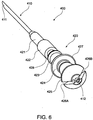
- retractable needle 400 comprises cannula 410 having delivery end 411 and fluid end 412.
- Retractable needle 400 further comprises needle body 420 which comprises respective body segments 421, 422, 423, 424 and 425.
- Body segment 425 comprises fluid channels 426A, 426B.
- Needle body segment 424 comprises shoulder 427 and needle body segment 422 comprises shoulder 428.
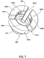
- ejector 600 comprises ejector ring 610, bore 605 and respective base segments 620A, B, C separated by slots 621A, B, C.
- Base segments 620A, B, C respectively comprise tabs 622A, B, C which as shown in FIG. 5 , engage shoulder 427 of body segment 424 of needle body 420.
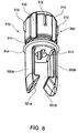
- retainer 300 comprises body 310 comprising circumferential groove 311, centering bosses 312, central aperture 313, rim 314 and guide channels 315, and further comprises arms 320A, 320B, respectively comprising hook-ends 321A, 321B.
- Circumferential groove 311 and guide channels 315 create zones which facilitate or guide the flow of glue or adhesive for adhering retainer 300 to inside wall 118 of barrel 110.
- Centering bosses 312 have been included to overcome the potential problem of centering retainer 300 in barrel 110 by providing a self-centering mechanism that simplifies centering of these components in high speed assembly and gluing machines, as would typically be used for the assembly of syringe 100.
- Centering bosses 312 allow contact between retainer 300 and barrel 110 at four separate points, with components produced for all extremes of tolerance.
- the tolerance variations between barrel 110 and retainer 300 are absorbed by the crushing of centering bosses 312.
- a gap would be required between these components to allow for assembly at all tolerance extremes, which would require automated assembly machines to have a system for centering the parts prior to gluing.
- centering would have to be performed by a mechanism external to, or otherwise separate from, the assembly machines. This would not be practical for high speed assembly.
- needle seal 430 comprises sealing base 431 which seals against inside wall 118 of barrel 110 to prevent inadvertent leakage of fluid contents, body 432 comprising internal bore 433 and ledge 434.
- plunger 200 is provided in an initial position ready for depression to deliver the fluid contents of the syringe 100.
- plunger 200 moves axially through barrel 110 in the direction of the hatched arrow in FIG. 9 .
- Plunger seal 800 bears against needle seal 430, which in turn bears against ejector 600 thereby pushing tabs 622A, B, C of ejector 600 out of engagement with needle body 420.
- tabs 622A, B, C allow for tuning of the force to disengage ejector 600 from needle body 420 by adjusting the height of the tabs 622 until the push force required on needle seal 430 to force ejector 600 out of engagement with shoulder 427 of needle body 420 is at a level that is acceptable for use of syringe 100.
- the design of tabs 622A, B, C provides for simple machining of the injection-moulding tool to provide the optimum engagement fit to provide acceptable disengagement.
- Ledge 434 of needle seal 430 now rests on shoulder 427 of needle body segment 424. This facilitates moving needle seal 430 back up barrel with the needle 400 on retraction (and serves as a stop for forward travel), Further to this, ejector ring 610 moves hook-ends 321A, B of arms 320A, B radially outwardly in the direction of the solid arrows in FIG. 9 , thereby disengaging segment 422 of needle body 420 from retainer 300 to release retractable needle 400 for subsequent retraction. At this point, recessed seat 810 of plunger seal 800 has engaged segment 425 of retractable needle body 420 and recess 860 has received fluid end 412 of cannula 410. This effectively couples retractable needle 400 to plunger member 210.
- fluid channels 426A, 426B in segment 425 and fluid conduit 826 in recessed seat 810 in plunger seal 800 assist in channeling residual fluid from within recessed seat 810 into fluid end 412 of cannula 410. This minimizes "dead volume” (i.e a volume of undeliverable, hence wasted, fluid contents) and reduces the possibility of a "hydraulic lock", to thereby improve the efficiency with which fluid contents of syringe 100 are delivered.
- plunger 200 moves axially in the direction of the hatched vertical arrow until the end of injection of fluid contents, at which time abutment 228 of locking finger 227 of plunger outer 220 engages underside 131 of release ring 130 to thereby prevent movement of plunger outer 220 out of barrel 110.
- compressed spring 270 In order for retractable needle 400 to retract at the end of delivery of fluid contents, compressed spring 270 must decompress, which is facilitated by plunger member 210 disengaging from plunger outer 220.
- arm 232 of control rod 230 bears against release ring 130 of collar 113 at plunger end 114 of barrel 110. Release ring 130 forces arm 232 to move radially inwardly n the direction of the horizontal solid arrow and out of engagement with rim 229 of cap member 223 of plunger outer 220 in FIG. 10 .
- This disengagement allows compressed spring 270 to decompress and push against ledge 212 of plunger member 210 to thereby retract plunger member 210 with control rod 230 coupled thereto, as shown in FIG. 11 .
- This disengagement may also be accompanied by an audible and/or tactile signal (e.g. a "click") which indicates to the user that retraction will occur.
- Retractable needle 400 is coupled to plunger seal 800 and so retracts with plunger member 210 in the direction of the arrow in FIG. 11 inside barrel 110, thereby being completely enveloped by, and contained within, barrel 110. While retraction of needle 400 is "automatically' driven by decompression of spring 270, the rate of retraction can be controlled by a user relaxing pressure (such as by way of thumb pressure) against button 231 of control rod 230.
- plunger member 210 at the end of retraction of plunger member 210, further movement of plunger member 210 relative to plunger outer 220 and/or barrel 110 is prevented by lock spring 224 "snap locking" around locking groove 219 in plunger member 210.
- lock spring 224 "snap locking" around locking groove 219 in plunger member 210.
- the locking of plunger member 210 at the end of retraction prevents inadvertent removal of plunger member 210 from plunger outer 220 and also prevents inadvertent depression of plunger member 210, both of which would expose needle end 411, and thereby expose the user to a potential needle stick injury.
- control rod 230 can be broken from plunger member 210 at frangible junction 234 and manually removed from retractable syringe 100 and discarded as "clean" waste so that there is little if any plunger 220 protruding externally from barrel 110 with which to attempt to force plunger 200 back into barrel 110 and attempt to re-engage the needle (not shown).
- the present invention provides a relatively simple, robust and inexpensive syringe that is automatically disabled with little or no assistance from the user to thereby prevent, or at least minimize the likelihood of, re-use of the syringe and/or needlestick injury by a used syringe.
- dual locking systems are provided whereby the plunger outer is locked to the barrel and the plunger member is locked to the plunger outer to thereby prevent removal and/or further movement of the plunger.
- the lock spring which can resist up to 100 Newtons force to prevent or impede further movement of the plunger member after retraction.
- the fluid conduits in the retractable needle body and in the plunger seal provide more efficient delivery of fluid contents timed to occur just before retraction of the needle.
- the fluid contents are an expensive drug or other compound, on a mass produced scale this improved efficiency can result in considerable cost savings.
- the retractable syringe retainer provides a convenient "self-centering" system for mounting into the barrel which greatly assists high speed syringe assembly.
- the guide channels of the retainer also assist rapid, automated adhesion of the retainer in the barrel during syringe assembly.
- ejector tabs described herein that provide an acceptable or desired level of retraction activation force. Adjustment of tab height allows for tuning of the force to disengage the ejector from the retractable needle body, and hence the "push" force required to force the ejector out of engagement with the retractable needle body.
Description
- THIS INVENTION relates to syringes. More particularly, this invention relates to a retractable syringe that includes at least one lock to prevent re-use of the syringe and/or needle stick injury and/or provides more efficient fluid delivery.
- The practice of sharing syringes without adequate sterilization between successive users is a major contributor to the transfer of Human Immunodeficiency Virus (HIV) and Hepatitis with subsequent severe repercussions for the sufferer and at a high cost to society for supporting and providing medical attention to sufferers.
- Furthermore, health professionals may be exposed to used syringes which can lead to inadvertent needle stick injuries and possible exposure to infective pathogens or other contaminants.
- In response to this problem, retractable syringes have been developed with the aim of preventing syringe re-use and/or needle stick injury by used syringes.
-
US 2008/0234635 A1 discloses a syringe including a needle cannula, a needle body and a plunger. The needle body comprises one or more fluid channels that in use co-operate with a plunger seal to direct fluid to said cannula. - A front abutment of the needle body facilitates withdrawal of the needle cannula after an injection. When the plunger is pressed forwards to move a grip member and the needle body forwardly, the front abutment of the needle body is moved into a triggering space to abut against a flange. Needle assemblies comprising ejectors which act on a needle retainer to facilitate needle retraction are described, for example, in
WO2006/108243 . - While retractable syringes have been developed with the aim of preventing syringe re-use and/or needle stick injury, there is still a need to improve the safety and efficiency of retractable syringes while keeping manufacturing costs to a minimum, particularly for mass produced retractable syringes.
- A preferred object of the invention is to provide a user friendly and safe retractable syringe while keeping manufacturing costs to a minimum, thereby facilitating mass production and distribution of retractable syringes.
- Another preferred object of the invention is to provide a retractable syringe which efficiently delivers fluid contents, thereby minimizing wastage of fluid contents.
- Yet another preferred object of the invention is to provide one or more locking systems to prevent or at least minimize syringe re-use and/or needle stick injury.
- According to an aspect of the present invention, there is provided a needle assembly according to claim 1.
- According to another aspect of the present invention, there is provided a retractable syringe according to claim 11.
- According to a further aspect of the present invention, there is provided a method of making a retractable syringe according to claim 13.
- Embodiments of the invention provide a needle assembly for a retractable syringe that comprises a barrel, a retractable needle, and a plunger comprising a plunger member, a plunger outer and one or more locking members.
- Suitably, a first said locking member in use prevents or impedes movement of said plunger member relative to said plunger outer and/or said barrel after needle retraction.
- In one embodiment, the first locking member is a lock spring mounted to the plunger outer.
- In another embodiment, the plunger comprises a second locking member. Preferably, the plunger outer comprises the second locking member which is capable of engaging the barrel. Suitably, the second locking member is capable of engaging the barrel, at the end of injection of fluid contents to thereby prevent or impede further movement of the plunger outer relative to the barrel.
- Preferably, the plunger further comprises a biasing member, wherein the plunger member and plunger outer co-operate to releasably maintain said biasing member in an initially energized state.
- Suitably, retraction of said retractable needle is facilitated by a release of energy from said biasing member.
- Non-limiting examples of biasing members include a spring, elastic or other device for storing releasable energy.
- Preferably, the biasing member is a spring which is initially compressed.
- In the context of the initially energized biasing member, or the initially compressed spring, it will be appreciated that energizing of the basing member or compression of the spring is performed during manufacture of the plunger or retractable syringe (i.e before supply to, or purchase or operation by, the user).
- In one embodiment, the plunger further comprises a retractable needle-engaging member.
- Preferably, the plunger further comprises a plunger seal.
- In one embodiment, the plunger seal is mounted to the plunger member.
- In one preferred embodiment, the plunger seal comprises said retractable needle-engaging member.
- In a particularly preferred embodiment, the plunger seal further comprises one or more fluid conduits.
- The plunger may further comprise a control rod. Preferably, the control rod is releasably connected to the plunger member. More preferably, the control rod is frangibly connected to the plunger member.
- Embodiments of the invention also provide a retractable syringe comprising a barrel; a retractable needle; and a plunger.
- Embodiments of the invention further provide a needle assembly comprising a retractable needle that comprises a cannula and a needle body comprising one or more conduits that in use direct fluid to said cannula.
- In use the one or more conduits co-operate with one or more fluid channels of a plunger seal to direct fluid to said cannula.
- Suitably, said needle body is engageable by a needle-engaging member of a plunger.
- The needle assembly further comprises a needle retainer releasably coupled to said needle body. In a preferred form, the needle retainer comprises a plurality of barbed arms that in use are releasably coupled to said needle body. the needle retainer comprises a plurality of centering bosses that facilitate self-centering of the needle retainer during syringe assembly. The needle retainer may comprise a plurality of guide channels which facilitate or guide the flow of glue or adhesive for adhering the needle retainer to the barrel during syringe assembly.
- The needle assembly further comprises an ejector.
- The ejector facilitates release of the retractable needle from the retainer to facilitate retraction of said retractable needle when engaged by said plunger.
- The ejector comprises a plurality of tabs that releasably engage said retractable needle.
- Preferably, said tabs provide an acceptable or desired level of retraction activation force for disengaging from the retractable needle.
- Preferably, the needle assembly further comprises a needle seal.
- Embodiments of the invention also provide a retractable syringe comprising a barrel and a needle assembly.
- Preferably, said barrel further comprises a collar having one or more releasing members that facilitate release of said controlling member from said plunger outer.
- Preferably, said syringe comprises a lock formed between said barrel or said collar and said plunger outer after injection of fluid contents of said syringe.
- Suitably, the syringe according to the aforementioned aspects is a prefilled syringe.
- In this context, "prefilled" means that the retractable syringe contains deliverable fluid contents before supply to, or purchase or operation by, the user. Accordingly, a prefilled syringe obviates the step of the user filling the syringe with fluid contents.
- In the aforementioned embodiments, typically, although not exclusively, the barrel is formed of glass.
- Embodiments of the invention also provide a method of making a retractable syringe by assembling a plunger, needle assembly and/or barrel.
- Suitably, the method includes the step of inserting a needle retainer into a barrel of the retractable syringe, the needle retainer comprising a plurality of centering bosses that facilitate self-centering of the needle retainer in the barrel.
- Preferably, the method includes the step of adhering the needle retainer to the barrel by providing a flow of adhesive through guide channels of said needle retainer.
- In a particularly preferred embodiment, the method of making the retractable syringe includes the sequential steps of:
- (i) mounting a needle assembly as hereinbefore described to a syringe barrel;
- (ii) filling the barrel with fluid contents;
- (iii) inserting a plunger seal into the barrel; and
- (iv) coupling a plunger to the plunger seal.
- Preferably, a collar comprising one or more releasing members is adhered to the barrel prior to step (ii).
- Throughout this specification, unless otherwise indicated, "comprise", "comprises" and "comprising" are used inclusively rather than exclusively, so that a stated integer or group of integers may include one or more other non-stated integers or groups of integers.
- Non-limiting embodiments of the invention are described herein with reference to the following drawings wherein:
-
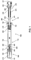
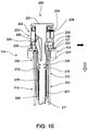
FIG. 1 is a sectional view of an embodiment of a retractable syringe; -
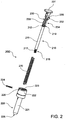
FIG. 2 is a sectional view of an embodiment of a plunger; -
FIG. 3 is a sectional view of an embodiment of a plunger immediately before the end of injection of fluid contents of a syringe; -
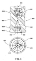
FIG. 4 is a sectional view and a bottom view of an embodiment of a plunger seal; -
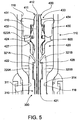
FIG. 5 is a sectional view of an embodiment of a needle assembly; -
FIG. 6 is a perspective view of an embodiment of a retractable needle; -
FIG. 7 is a perspective view of an embodiment of an ejector; -
FIG. 8 is a perspective view of an embodiment of a retainer; -
FIG. 9 is a sectional view of an embodiment of a needle assembly immediately before retraction of a retractable needle; -
FIG. 10 is a sectional view of an embodiment of a plunger immediately before retraction; -
FIG. 11 is a sectional view of an embodiment of a syringe during retraction of a plunger and retractable needle engaged therewith; and -
FIG. 12 is a sectional view of a lock formed between a barrel collar and a plunger outer after plunger retraction. - Referring to
FIG. 1 , an embodiment ofretractable syringe 100 comprisesbarrel 110 having plunger end 114 andneedle end 115.Barrel 110 is preferably formed of glass. Atplunger end 114 is locatedcollar 113 having a releasing member in the form ofrelease ring 130.Collar 113 may be mounted, glued, fitted or integrally formed withbarrel 110. In embodiments wherebarrel 110 is formed of glass, suitablycollar 113 is glued or otherwise adhered tobarrel 110. In embodiments wherebarrel 110 is formed of plastic,collar 113 is preferably formed integrally with barrel 110 (e.g by moulding).Release ring 130 may be mounted, adhered or otherwise fitted tobarrel 110, or may be co-moulded withcollar 113 andbarrel 110. - At
needle end 115 ofbarrel 110 is mountedneedle assembly 900 comprisingretractable needle 400 that comprisescannula 410 andneedle body 420,needle seal 430,ejector 600 andretainer 300. Typically,syringe 100 is supplied with removableprotective cover 121 overcannula 410. -
Syringe 100 further comprisesplunger 200 comprisingplunger seal 800 mounted thereto.Barrel 110 further comprises insidewall 118 which, together withneedle seal 430 andplunger seal 800 definefluid space 120 insidebarrel 110. In a preferred embodiment,fluid space 120 is prefilled with fluid contents to be delivered byretractable syringe 100. - Typically,
barrel 110 is formed of glass. Preferably,retainer 300 is glued or otherwise adhered toinside wall 118 ofbarrel 110. In use,plunger 200 is movable axially intofluid space 120 to facilitate delivery of fluid contents ofretractable syringe 100. - Referring particularly to
FIG. 2 ,FIG. 3 andFIG. 4 ,plunger 200 comprisesplunger member 210 comprisingshaft 211,annular ledge 212 and seal-engagingmember 216, which in this embodiment is screw threadedprojection 217, which engages complementary, screw-threadedrecess 820 of plunger seal 800 (seeFIG. 4 ). In an alternative embodiment,seal engaging member 216 may be in the form of a snap lock projection that engages a complementary recess inplunger seal 800. In either case, the male-female connection betweenplunger member 210 andplunger seal 800 may readily be reversed so that theplunger member 210 has the female member and theplunger seal 800 has the male member. -
Plunger member 210 further comprises lockinggroove 219, the function of which will be described in more detail hereinafter. -
Plunger 200 further comprises plunger outer 220 havingelongate body 221 withbase 225 andhead 222 in which is fittedcap 223. A first locking member compriseslock spring 224 mounted throughslot 226 extending throughhead 222 andcap 223 to thereby assist assembly ofplunger 200. Typically,lock spring 224 is an "R-shape' clip of stainless steel construction.Lock spring 224 and lockinggroove 219 co-operate to lockplunger member 210 and plunger outer 220 together at the end of retraction, as will be described in more detail hereinafter with reference toFIG. 12 .Lock spring 224 preferably provides up to 100 Newton lockout resistance, which is a level of resistance desirable forsyringe 100. -
Elongate body 221 further comprises a second locking member comprising lockingfinger 227 which hasabutment 228. Engagement between lockingfinger 227 andrelease ring 130 ofcollar 113 will also be described in more detail hereinafter with reference toFIG. 12 . - Releasably, frangibly connected with
plunger member 210 iscontrol rod 230 comprisingbutton 231,arm 232 andshaft 233.Plunger 200 further comprises compressedspring 270 which is mounted betweenplunger member 210 and plunger outer 220, held in an initially compressed state betweenannular ledge 212 ofplunger member 210 andbase 225 of plunger outer 220.Button 231 may have a textured surface to improve feel and grip for a user. - As best shown in
FIG. 3 ,control rod 230 is releasably coupled toplunger member 210 by way ofshaft 233 which is releasably connected toplunger member 210 byfrangible junction 234.Control rod 230 also releasably engages plunger outer 220 to thereby retainspring 270 in an initially compressed state held betweenannular ledge 212 ofplunger member 210 andbase 225 of plunger outer 220. Initially,ledge 235 ofarm 232 abuts rim 229 ofhead 222 of plunger outer 220 to thereby retaincontrol rod 230 and prevent axial movement ofcontrol rod 230 relative to plunger outer 220. However,arm 232 ofcontrol rod 230 is resiliently flexible and movable in the direction of the solid arrow shown inFIG. 3 , which will allow disengagement ofcontrol rod 230 from plunger outer 220 to facilitate decompression ofspring 270, as will be described in detail hereinafter. - Referring particularly to
FIG. 4 ,plunger seal 800 is of unitary construction and comprisesseal body 840 and sealingribs plunger 200 and insidewall 118 ofbarrel 110. Recess 820 ofplunger seal 800 engages complementary seal-engagingmember 216 of plunger member 210 (seeFIG. 9 ). In this embodiment,recess 820 comprises afemale screw thread 821 that engages male screw threadedprojection 217 of plunger member.Plunger seal 800 further comprises needle engaging member in the form of recessedseat 810 that can receivesegment 425 ofretractable needle body 420.Plunger seal 800 also comprisesrecess 860 that receivesfluid end 412 ofcannula 410 towards the end ofplunger 200 depression, prior to retraction ofretractable needle 400, as will be described hereinafter. In addition,recess 860 ofplunger seal 800 comprisesfluid conduit 826. -
Needle assembly 900 is shown in more detail inFIG. 5 , which comprisesretractable needle 400,retainer 300,needle seal 430 andejector 600. These components are individually described with reference toFIGS. 6 ,7 and8 respectively. Referring toFIG. 6 ,retractable needle 400 comprisescannula 410 havingdelivery end 411 andfluid end 412.Retractable needle 400 further comprisesneedle body 420 which comprisesrespective body segments Body segment 425 comprisesfluid channels Needle body segment 424 comprisesshoulder 427 andneedle body segment 422 comprisesshoulder 428. InFIG. 7 ,ejector 600 comprisesejector ring 610, bore 605 andrespective base segments 620A, B, C separated byslots 621A, B,C. Base segments 620A, B, C respectively comprisetabs 622A, B, C which as shown inFIG. 5 , engageshoulder 427 ofbody segment 424 ofneedle body 420. - Referring to
FIG. 8 ,retainer 300 comprisesbody 310 comprisingcircumferential groove 311, centeringbosses 312,central aperture 313,rim 314 and guidechannels 315, and further comprisesarms Circumferential groove 311 and guidechannels 315 create zones which facilitate or guide the flow of glue or adhesive for adheringretainer 300 toinside wall 118 ofbarrel 110. Centeringbosses 312 have been included to overcome the potential problem of centeringretainer 300 inbarrel 110 by providing a self-centering mechanism that simplifies centering of these components in high speed assembly and gluing machines, as would typically be used for the assembly ofsyringe 100. Centeringbosses 312 allow contact betweenretainer 300 andbarrel 110 at four separate points, with components produced for all extremes of tolerance. The tolerance variations betweenbarrel 110 andretainer 300 are absorbed by the crushing of centeringbosses 312. In the absence of these structures, a gap would be required between these components to allow for assembly at all tolerance extremes, which would require automated assembly machines to have a system for centering the parts prior to gluing. Alternatively, centering would have to be performed by a mechanism external to, or otherwise separate from, the assembly machines. This would not be practical for high speed assembly. - Referring again to
FIG. 5 ,needle seal 430 comprises sealingbase 431 which seals againstinside wall 118 ofbarrel 110 to prevent inadvertent leakage of fluid contents,body 432 comprisinginternal bore 433 andledge 434. - The sequence of events whereby
retractable needle 400 is disengaged fromretainer 300 to facilitate retraction ofretractable needle 400 is as follows. - Typically,
syringe 100 is provided prefilled with fluid contents for delivery. Therefore,plunger 200 is provided in an initial position ready for depression to deliver the fluid contents of thesyringe 100. During delivery of fluid contents,plunger 200 moves axially throughbarrel 110 in the direction of the hatched arrow inFIG. 9 .Plunger seal 800 bears againstneedle seal 430, which in turn bears againstejector 600 thereby pushingtabs 622A, B, C ofejector 600 out of engagement withneedle body 420. In order to provide an acceptable or desired level of retraction activation force,tabs 622A, B, C allow for tuning of the force to disengageejector 600 fromneedle body 420 by adjusting the height of the tabs 622 until the push force required onneedle seal 430 to forceejector 600 out of engagement withshoulder 427 ofneedle body 420 is at a level that is acceptable for use ofsyringe 100. The design oftabs 622A, B, C provides for simple machining of the injection-moulding tool to provide the optimum engagement fit to provide acceptable disengagement. -
Ledge 434 ofneedle seal 430 now rests onshoulder 427 ofneedle body segment 424. This facilitates movingneedle seal 430 back up barrel with theneedle 400 on retraction (and serves as a stop for forward travel), Further to this,ejector ring 610 moves hook-ends 321A, B ofarms 320A, B radially outwardly in the direction of the solid arrows inFIG. 9 , thereby disengagingsegment 422 ofneedle body 420 fromretainer 300 to releaseretractable needle 400 for subsequent retraction. At this point, recessedseat 810 ofplunger seal 800 has engagedsegment 425 ofretractable needle body 420 andrecess 860 has receivedfluid end 412 ofcannula 410. This effectively couplesretractable needle 400 toplunger member 210. Although not visible inFIG. 9 ,fluid channels segment 425 andfluid conduit 826 in recessedseat 810 inplunger seal 800 assist in channeling residual fluid from within recessedseat 810 intofluid end 412 ofcannula 410. This minimizes "dead volume" (i.e a volume of undeliverable, hence wasted, fluid contents) and reduces the possibility of a "hydraulic lock", to thereby improve the efficiency with which fluid contents ofsyringe 100 are delivered. - Referring to
FIG. 10 ,plunger 200 moves axially in the direction of the hatched vertical arrow until the end of injection of fluid contents, at whichtime abutment 228 of lockingfinger 227 of plunger outer 220 engagesunderside 131 ofrelease ring 130 to thereby prevent movement of plunger outer 220 out ofbarrel 110. - In order for
retractable needle 400 to retract at the end of delivery of fluid contents,compressed spring 270 must decompress, which is facilitated byplunger member 210 disengaging from plunger outer 220. Again referring toFIG. 10 ,arm 232 ofcontrol rod 230 bears againstrelease ring 130 ofcollar 113 atplunger end 114 ofbarrel 110.Release ring 130 forces arm 232 to move radially inwardly n the direction of the horizontal solid arrow and out of engagement withrim 229 ofcap member 223 of plunger outer 220 inFIG. 10 . This disengagement allows compressedspring 270 to decompress and push againstledge 212 ofplunger member 210 to thereby retractplunger member 210 withcontrol rod 230 coupled thereto, as shown inFIG. 11 . This disengagement may also be accompanied by an audible and/or tactile signal (e.g. a "click") which indicates to the user that retraction will occur.Retractable needle 400 is coupled toplunger seal 800 and so retracts withplunger member 210 in the direction of the arrow inFIG. 11 insidebarrel 110, thereby being completely enveloped by, and contained within,barrel 110. While retraction ofneedle 400 is "automatically' driven by decompression ofspring 270, the rate of retraction can be controlled by a user relaxing pressure (such as by way of thumb pressure) againstbutton 231 ofcontrol rod 230. - Referring to
FIG. 12 , at the end of retraction ofplunger member 210, further movement ofplunger member 210 relative to plunger outer 220 and/orbarrel 110 is prevented bylock spring 224 "snap locking" around lockinggroove 219 inplunger member 210. The locking ofplunger member 210 at the end of retraction prevents inadvertent removal ofplunger member 210 from plunger outer 220 and also prevents inadvertent depression ofplunger member 210, both of which would exposeneedle end 411, and thereby expose the user to a potential needle stick injury. - At the end of retraction of
plunger member 210 andretractable needle 400,control rod 230 can be broken fromplunger member 210 atfrangible junction 234 and manually removed fromretractable syringe 100 and discarded as "clean" waste so that there is little if anyplunger 220 protruding externally frombarrel 110 with which to attempt to forceplunger 200 back intobarrel 110 and attempt to re-engage the needle (not shown). - In light of the foregoing it will be appreciated that the present invention provides a relatively simple, robust and inexpensive syringe that is automatically disabled with little or no assistance from the user to thereby prevent, or at least minimize the likelihood of, re-use of the syringe and/or needlestick injury by a used syringe.
- More particularly, dual locking systems are provided whereby the plunger outer is locked to the barrel and the plunger member is locked to the plunger outer to thereby prevent removal and/or further movement of the plunger. Another particular advantage is provided by the lock spring which can resist up to 100 Newtons force to prevent or impede further movement of the plunger member after retraction. By providing dual locking systems, inadvertent failure of one or the other locking systems, or overcoming one or the other locking systems through tampering by an illicit user, does not result in the complete failure of plunger lockout.
- It will also be appreciated that the fluid conduits in the retractable needle body and in the plunger seal provide more efficient delivery of fluid contents timed to occur just before retraction of the needle. In cases where the fluid contents are an expensive drug or other compound, on a mass produced scale this improved efficiency can result in considerable cost savings. Furthermore, the retractable syringe retainer provides a convenient "self-centering" system for mounting into the barrel which greatly assists high speed syringe assembly. The guide channels of the retainer also assist rapid, automated adhesion of the retainer in the barrel during syringe assembly.
- Another advantage is provided by the ejector tabs described herein that provide an acceptable or desired level of retraction activation force. Adjustment of tab height allows for tuning of the force to disengage the ejector from the retractable needle body, and hence the "push" force required to force the ejector out of engagement with the retractable needle body.
- Throughout the specification, the aim has been to describe the preferred embodiments of the invention without limiting the invention to any one embodiment or specific collection of features. Various changes and modifications may be made to the embodiments described and illustrated without departing from the present invention.
Claims (14)
- A needle assembly (900) comprising a retractable needle (400) that comprises a cannula (410) and a needle body (420) comprising one or more fluid channels (426A, 426B) that in use co-operate with one or more fluid conduits (826) of a plunger seal (800) to direct fluid to said cannula and further comprising a needle retainer (300) releasably coupled to said needle body (420) characterized in that the assembly also comprises an ejector (600) that facilitates release of the retractable needle (400) from the retainer (300) to allow retraction of said retractable needle (400) when engaged by said plunger seal (800), the ejector (600) comprising a plurality of tabs (622A, 622B, 622C) that releasably engage the needle body (420).
- The needle assembly of Claim 1, wherein the needle body (420) is engageable by a needle-engaging member (810) of said plunger seal (800) to facilitate retraction of said retractable needle (400).
- The needle assembly of Claim 1 or Claim 2, wherein the needle retainer (300) comprises a plurality of barbed arms (320A, 320B) that in use are releasably coupled to said needle body (420).
- The needle assembly of Claim 3, wherein the needle retainer (300) comprises a plurality of centering bosses (312) that facilitate self-centering of the needle retainer (300) during syringe (100) assembly.
- The needle assembly of any one of Claims 1 to 4, wherein the needle retainer (300) comprises a plurality of guide channels (315) which facilitate or guide the flow of glue or adhesive for adhering the needle retainer (300) to a syringe barrel (100) during syringe assembly.
- The needle assembly of any preceding claim, wherein said tabs (622A, 622B, 622C) provide an acceptable or desired level of retraction activation force for disengaging the retractable needle.
- The needle assembly of any preceding claim, wherein the needle body (420) comprises respective body segments (421, 422, 423, 424, 425).
- The needle assembly of Claim 7, wherein the plurality of tabs (622A, 622B, 622C) releasably engage a shoulder (427) of one of said body segments (424) of the needle body (420).
- The needle assembly of Claim 7 or 8, wherein one of said body segments (425) comprises said fluid channels (426A, 426B).
- The needle assembly of any one of Claims 1-9, which further comprises a needle seal (430).
- A retractable syringe (100) comprising a barrel (110), a plunger (200) and the needle assembly (900) of any one of Claims 1-10.
- The retractable syringe of Claim 11, wherein the plunger (200) comprises a plunger member (210) comprising a plunger seal (800) having one or more fluid conduits (826), a plunger outer (220) and one or more locking members, a first of said one or more locking members (224, 227) mounted to the plunger outer (220) and capable of preventing or impeding further movement of said plunger member (210) relative to said plunger outer (220) and/or said barrel (110) after needle retraction.
- A method of making a retractable syringe (100) including the step of inserting a needle retainer (300) of the needle assembly (900) of Claim 1 into a barrel (110) of the retractable syringe (100), the needle retainer (300) comprising a plurality of centering bosses (312) that facilitate self-centering of the needle retainer (300) in the barrel (110).
- The method of Claim 13, including the step of adhering the needle retainer (300) to the barrel (110) by providing a flow of adhesive through guide channels (315) of said needle retainer (300).
Applications Claiming Priority (3)
| Application Number | Priority Date | Filing Date | Title |
|---|---|---|---|
| US28925909P | 2009-12-22 | 2009-12-22 | |
| PCT/AU2010/001677 WO2011075760A1 (en) | 2009-12-22 | 2010-12-10 | Retractable syringe with improved delivery efficiency and locking system |
| EP10838400.9A EP2515976B1 (en) | 2009-12-22 | 2010-12-10 | Retractable syringe with improved delivery efficiency and locking system |
Related Parent Applications (2)
| Application Number | Title | Priority Date | Filing Date |
|---|---|---|---|
| EP10838400.9A Division-Into EP2515976B1 (en) | 2009-12-22 | 2010-12-10 | Retractable syringe with improved delivery efficiency and locking system |
| EP10838400.9A Division EP2515976B1 (en) | 2009-12-22 | 2010-12-10 | Retractable syringe with improved delivery efficiency and locking system |
Publications (2)
| Publication Number | Publication Date |
|---|---|
| EP2918302A1 EP2918302A1 (en) | 2015-09-16 |
| EP2918302B1 true EP2918302B1 (en) | 2018-11-14 |
Family
ID=44194806
Family Applications (2)
| Application Number | Title | Priority Date | Filing Date |
|---|---|---|---|
| EP15162052.3A Not-in-force EP2918302B1 (en) | 2009-12-22 | 2010-12-10 | Retractable syringe with improved delivery efficiency and locking system |
| EP10838400.9A Not-in-force EP2515976B1 (en) | 2009-12-22 | 2010-12-10 | Retractable syringe with improved delivery efficiency and locking system |
Family Applications After (1)
| Application Number | Title | Priority Date | Filing Date |
|---|---|---|---|
| EP10838400.9A Not-in-force EP2515976B1 (en) | 2009-12-22 | 2010-12-10 | Retractable syringe with improved delivery efficiency and locking system |
Country Status (19)
| Country | Link |
|---|---|
| US (3) | US8945048B2 (en) |
| EP (2) | EP2918302B1 (en) |
| JP (2) | JP5785190B2 (en) |
| KR (1) | KR101875172B1 (en) |
| CN (1) | CN102791312B (en) |
| AU (1) | AU2010336003B2 (en) |
| BR (1) | BR112012015520A2 (en) |
| CA (1) | CA2784437C (en) |
| DK (2) | DK2918302T3 (en) |
| ES (1) | ES2550246T3 (en) |
| HK (1) | HK1175723A1 (en) |
| IL (2) | IL220366A (en) |
| MX (2) | MX2012007116A (en) |
| NZ (2) | NZ601140A (en) |
| PT (2) | PT2918302T (en) |
| SG (1) | SG181849A1 (en) |
| TW (2) | TWI494145B (en) |
| WO (1) | WO2011075760A1 (en) |
| ZA (1) | ZA201204653B (en) |
Families Citing this family (55)
| Publication number | Priority date | Publication date | Assignee | Title |
|---|---|---|---|---|
| JP2008275319A (en) * | 2005-08-16 | 2008-11-13 | Univ Of Yamanashi | Portable young's modulus measuring device and method, and breaking strength measuring device |
| US20070202186A1 (en) | 2006-02-22 | 2007-08-30 | Iscience Interventional Corporation | Apparatus and formulations for suprachoroidal drug delivery |
| US8197435B2 (en) | 2006-05-02 | 2012-06-12 | Emory University | Methods and devices for drug delivery to ocular tissue using microneedle |
| KR101875172B1 (en) | 2009-12-22 | 2018-07-06 | 유니트랙트 시린지 피티와이 엘티디 | Retractable syringe with improved delivery efficiency and locking system |
| CN104758118B (en) | 2010-10-15 | 2018-04-06 | 科尼尔赛德生物医学公司 | For entering the device of eyes |
| US9084849B2 (en) | 2011-01-26 | 2015-07-21 | Kaleo, Inc. | Medicament delivery devices for administration of a medicament within a prefilled syringe |
| US9205194B2 (en) | 2011-08-05 | 2015-12-08 | Unitract Syringe Pty Ltd | Dual chamber mixing device for a syringe |
| ES2572578T3 (en) * | 2011-08-24 | 2016-06-01 | Unitract Syringe Pty Ltd | Autoinjector for prefilled retractable syringe |
| US9821118B2 (en) | 2011-09-02 | 2017-11-21 | Unl Holdings Llc | Automatic reconstitution for dual chamber syringe |
| US9604010B2 (en) * | 2011-11-09 | 2017-03-28 | Unitract Syringe Pty Ltd | Retractable syringe needle |
| EP2596822A1 (en) * | 2011-11-24 | 2013-05-29 | Sanofi-Aventis Deutschland GmbH | Autoinjector |
| EP2596823A1 (en) * | 2011-11-24 | 2013-05-29 | Sanofi-Aventis Deutschland GmbH | Autoinjector |
| EP2596826A1 (en) * | 2011-11-24 | 2013-05-29 | Sanofi-Aventis Deutschland GmbH | Safety syringe |
| WO2017204787A1 (en) | 2011-12-08 | 2017-11-30 | Unitract Syringe Pty Ltd | Accurate dose control mechanisms and drug delivery syringes |
| IN2014CN04000A (en) | 2011-12-08 | 2015-10-23 | Unitract Syringe Pty Ltd | |
| US10300201B2 (en) | 2012-02-06 | 2019-05-28 | Unl Holdings Llc | Plunger sub-assemblies and auto-injectors having low retraction activation force |
| CN104334214B (en) * | 2012-05-30 | 2017-09-05 | 赛诺菲-安万特德国有限公司 | Piston rod for delivery device and the delivery device including piston rod |
| RU2649473C2 (en) | 2012-07-05 | 2018-04-03 | Юнитрект Сириндж Пти Лтд | Automatic injectors for injectable cartridges and drive control mechanism therefor |
| TWI564047B (en) * | 2012-08-03 | 2017-01-01 | Unitract Syringe Pty Ltd | Double chamber mixing device for syringe and combination method thereof and syringe using double chamber mixing device and manufacturing method thereof |
| CA2890471C (en) | 2012-11-08 | 2021-07-27 | Clearside Biomedical, Inc. | Methods and devices for the treatment of ocular diseases in human subjects |
| JP6325562B2 (en) | 2012-11-09 | 2018-05-16 | イインジェック テクノロジーズ インコーポレイテッド | Fluid delivery apparatus and method |
| WO2014085118A1 (en) | 2012-11-30 | 2014-06-05 | Unitract Syringe Pty Ltd | Combination plunger device for a dual chamber mixing syringe |
| EP2978479A1 (en) | 2013-03-28 | 2016-02-03 | Unitract Syringe Pty Ltd | Needle capture retractable needle safety syringes |
| EP2991705B1 (en) | 2013-05-01 | 2019-10-16 | UNL Holdings LLC | Plunger-driven auto-injectors |
| WO2014179698A2 (en) | 2013-05-03 | 2014-11-06 | Clearside Biomedical, Inc. | Apparatus and methods for ocular injection |
| WO2014197317A1 (en) | 2013-06-03 | 2014-12-11 | Clearside Biomedical, Inc. | Apparatus and methods for drug delivery using multiple reservoirs |
| EP3581222A1 (en) | 2013-06-04 | 2019-12-18 | UNL Holdings LLC | Actuation mechanisms for dual chamber mixing syringes |
| US9919110B2 (en) | 2013-07-01 | 2018-03-20 | Credence Medsystems, Inc. | Safety syringe |
| USD764657S1 (en) | 2013-07-03 | 2016-08-23 | Unitract Syringe Pty Ltd | Automatic injector |
| US9597454B2 (en) | 2013-07-16 | 2017-03-21 | Unitract Syringe Pty Ltd. | Syringes for prefilled and fill-at-use mixing and drug delivery |
| WO2015021261A1 (en) * | 2013-08-07 | 2015-02-12 | Unitract Syringe Pty Ltd | Luer connection adapters for retractable needle syringes |
| EP3030291A2 (en) | 2013-08-07 | 2016-06-15 | Unitract Syringe Pty Ltd | Retainer for retractable needle assemblies and syringes |
| CN105658266A (en) * | 2013-08-22 | 2016-06-08 | 赛诺菲-安万特德国有限公司 | Assembly for a drug delivery device and use of an attenuation member |
| AU2014348292B2 (en) * | 2013-11-15 | 2019-05-23 | Credence Medsystems Inc. | System and method for drug delivery with a safety syringe |
| EP3102261A4 (en) | 2014-02-03 | 2017-11-08 | UNL Holdings LLC | Selectable needle syringe with retraction plunger |
| CA2980443C (en) | 2014-04-24 | 2024-03-05 | Credence Medsystems Inc. | System and method for safety syringe |
| CN106794321A (en) | 2014-06-20 | 2017-05-31 | 科尼尔赛德生物医学公司 | Variable-diameter intubation and for controlling the method to the insertion depth of drug delivery |
| MX2017002428A (en) | 2014-08-28 | 2017-05-15 | Unitract Syringe Pty Ltd | Sensor systems for drug delivery devices. |
| USD750223S1 (en) | 2014-10-14 | 2016-02-23 | Clearside Biomedical, Inc. | Medical injector for ocular injection |
| KR20170097020A (en) | 2014-12-23 | 2017-08-25 | 오토메드 피티와이 리미티드 | Delivery apparatus, system and associated methods |
| GB2556479B (en) | 2015-06-30 | 2022-09-07 | Kaleo Inc | Auto-injectors for administration of a medicament within a prefilled syringe |
| EP3413851B1 (en) | 2016-02-10 | 2023-09-27 | Clearside Biomedical, Inc. | Packaging |
| EP3207952A1 (en) | 2016-02-16 | 2017-08-23 | Carebay Europe Ltd. | An automatic feedback mechanism and a medicament delivery device with user feedback capability |
| KR102179603B1 (en) | 2016-02-24 | 2020-11-19 | 에스에이치엘 메디컬 아게 | Safety device for drug delivery device and drug delivery device including the same |
| JP2019514581A (en) | 2016-05-02 | 2019-06-06 | クリアサイド バイオメディカル,インコーポレイテッド | Systems and methods for ocular drug delivery |
| IL264764B2 (en) | 2016-08-12 | 2024-02-01 | Clearside Biomedical Inc | Devices and methods for adjusting the insertion depth of a needle for medicament delivery |
| WO2018085467A2 (en) * | 2016-11-01 | 2018-05-11 | Credence Medsystems, Inc. | System and method for safety syringe |
| JP7014797B2 (en) | 2016-12-23 | 2022-02-01 | カレオ,インコーポレイテッド | Drug delivery devices and methods for delivering drugs to babies and children |
| CN111491680B (en) | 2017-12-13 | 2023-08-29 | 里珍纳龙药品有限公司 | Device and method for accurate dose delivery |
| EP3738629B1 (en) * | 2019-05-16 | 2023-03-08 | Trenta2 S.r.l. | Medical syringe with needle shield |
| CN113966240A (en) | 2019-06-05 | 2022-01-21 | 里珍纳龙药品有限公司 | Device and method for precise dose delivery |
| JP2022543523A (en) | 2019-08-09 | 2022-10-13 | カレオ,インコーポレイテッド | Device and method for delivery of substances in pre-filled syringes |
| WO2022053126A1 (en) * | 2020-09-08 | 2022-03-17 | Trenta2 S.r.l. | Medical syringe with passive needle guard |
| CN116669797A (en) * | 2020-09-14 | 2023-08-29 | 特伦塔2公司 | Medical injector with needle guard |
| CN115040763B (en) * | 2022-06-07 | 2023-08-18 | 中国人民解放军空军军医大学 | Portable decompression suction filtration device micropump is used in laboratory |
Citations (1)
| Publication number | Priority date | Publication date | Assignee | Title |
|---|---|---|---|---|
| WO2006108243A2 (en) * | 2005-04-15 | 2006-10-19 | Unitract Syringe Pty Ltd | Controlled retraction syringe and plunger therefor |
Family Cites Families (49)
| Publication number | Priority date | Publication date | Assignee | Title |
|---|---|---|---|---|
| US4950241A (en) * | 1988-12-27 | 1990-08-21 | Sherwood Medical Company | Disposable syringe |
| US4994034A (en) * | 1989-07-11 | 1991-02-19 | Botich Michael J | Retractable needle hypodermic syringe system |
| US5114404A (en) * | 1990-07-24 | 1992-05-19 | Paxton Gerald R | Multifunctional retractable needle type general purpose disabling syringe having enhanced safety features and related method of operation |
| US5205824A (en) * | 1991-06-13 | 1993-04-27 | Mazur Matthew S | Retractable syringe with a closed barrel |
| US5211628A (en) * | 1991-09-30 | 1993-05-18 | Marshall John M | Syringe with automatic retracting needle |
| US5401249A (en) * | 1993-06-07 | 1995-03-28 | Shields; Jack W. | Safely disposable, non-reusable injection device |
| US5395337A (en) * | 1993-08-31 | 1995-03-07 | Clemens; Anton H. | Needle retraction system |
| US5423758A (en) * | 1993-12-16 | 1995-06-13 | Shaw; Thomas J. | Retractable fluid collection device |
| US5876382A (en) * | 1996-06-14 | 1999-03-02 | Ultimed, Inc | Safety syringe with retractable needle holder |
| US5800395A (en) * | 1996-12-05 | 1998-09-01 | Mdc Investment Holdings, Inc. | Medical device with retractable needle |
| DE19705892C1 (en) | 1997-02-15 | 1998-11-12 | Siekmann Gmbh | Universal safety syringe |
| AUPO940697A0 (en) * | 1997-09-23 | 1997-10-16 | Kaal, Joseph Hermes | Retractable syringe |
| GB2341804B (en) | 1998-09-25 | 2003-02-12 | David William Parker | Improvements in or relating to hypodermic syringes |
| GB2351804B (en) * | 1999-06-28 | 2003-09-24 | Hyundai Electronics Ind | Semiconductor factory automation system and method for controlling measurement equipment to measure semiconductor wafers |
| CA2278390C (en) | 1999-07-19 | 2003-10-07 | Yu-Hau Chang-Lai | Safety syringe |
| US6086568A (en) * | 1999-10-15 | 2000-07-11 | Becton Dickinson And Company | Syringe plunger rod for retracting needle syringe |
| FR2799976B1 (en) * | 1999-10-26 | 2002-06-21 | Plastic Omnium Cie | SAFETY DEVICE FOR INJECTION SYRINGE |
| EP1233803B1 (en) * | 1999-11-29 | 2006-02-15 | MDC Investment Holdings, Inc. | Combination safety needle assembly and medical apparatus |
| AU5201901A (en) * | 2000-04-26 | 2001-11-07 | Craig Stephen Thorley | Single use syringe |
| US6432087B1 (en) * | 2000-07-31 | 2002-08-13 | Becton, Dickinson And Company | Hypodermic syringe with selectively retractable needle |
| US6413237B1 (en) | 2000-08-31 | 2002-07-02 | Becton, Dickinson And Company | Hypodermic syringe with selectively retractable needle |
| MXPA03008004A (en) * | 2001-03-15 | 2004-10-15 | Mdc Invest Holdings Inc | Retractable needle medical device for injecting fluid from a pre-filled cartridge. |
| US6776777B2 (en) * | 2002-05-10 | 2004-08-17 | Becton, Dickinson And Company | Passive safety shield system for injection devices |
| US6808507B2 (en) * | 2002-05-10 | 2004-10-26 | Cambridge Biostability Ltd. | Safety injectors |
| GB0222731D0 (en) * | 2002-10-01 | 2002-11-06 | Parker David W | Improvements in or relating to hypodermic syringes |
| PT1608421E (en) * | 2003-03-20 | 2013-07-26 | Unitract Syringe Pty Ltd | Syringe spring retainer |
| TWI250878B (en) * | 2003-04-22 | 2006-03-11 | Ming-Jeng Shiu | Disposable syringe |
| ATE403457T1 (en) | 2003-09-09 | 2008-08-15 | Ping-Te Huang | SYRINGE HAVING A HOLDING ELEMENT HAVING AN INTEGRAL ANNUAL RIB |
| US6979314B2 (en) | 2003-10-14 | 2005-12-27 | Syriteck Medical Devices Co., Ltd. | Safety syringe |
| US7468054B2 (en) * | 2003-11-03 | 2008-12-23 | Becton, Dickinson And Company | Safety shield system for a syringe |
| GB2410188B (en) * | 2004-01-23 | 2006-01-25 | Medical House Plc | Injection device |
| CA2554196C (en) * | 2004-01-28 | 2011-12-20 | Unitract Syringe Pty Ltd | Retractable syringe with plunger disabling system |
| TWI282743B (en) * | 2004-01-28 | 2007-06-21 | Unitract Syringe Pty Ltd | Automatically disabled syringe |
| EP1791583A4 (en) * | 2004-07-16 | 2016-08-17 | Unitract Syringe Pty Ltd | Syringe needle sheath |
| ES2386025T3 (en) | 2004-10-14 | 2012-08-07 | Midland Medical Devices Holdings, Llc | Medical safety syringe with retractable needle |
| WO2006119570A1 (en) * | 2005-05-12 | 2006-11-16 | Unitract Syringe Pty Ltd | Improved controlled retraction syringe and plunger therefor |
| AU2005336322A1 (en) * | 2005-09-06 | 2007-03-15 | Global Medisafe Holdings Pty Limited | Single use safety syringe having a retractable needle |
| US7846135B2 (en) * | 2006-02-24 | 2010-12-07 | Midland Medical Holding LLC | Retractable needle syringe with needle trap |
| TW200838573A (en) * | 2007-03-19 | 2008-10-01 | ming-zheng Xu | Injector with safety device |
| NZ595031A (en) * | 2007-07-02 | 2012-02-24 | Unitract Syringe Pty Ltd | Automatically retracting syringe with spring based mechanisim |
| US7824381B2 (en) * | 2007-11-16 | 2010-11-02 | Lien-Tsang Lee | Safety disposable syringe |
| JP2008142565A (en) * | 2008-01-29 | 2008-06-26 | Retractable Technologies Inc | Single-use retractable syringe equipped with positive needle holding |
| US20100010450A1 (en) * | 2008-06-13 | 2010-01-14 | Vincent Runfola | Retractable syringe with improved stem ring and needle interchangeability |
| AU2010262752B2 (en) * | 2009-06-17 | 2013-08-22 | Unitract Syringe Pty Ltd | Syringe adapter |
| AU2010317659B2 (en) * | 2009-11-11 | 2014-01-23 | Unitract Syringe Pty Ltd | Clinical syringe |
| CN102725014B (en) * | 2009-11-11 | 2016-01-27 | 尤尼特拉克特注射器公司 | Vaccine syringe |
| KR101875172B1 (en) * | 2009-12-22 | 2018-07-06 | 유니트랙트 시린지 피티와이 엘티디 | Retractable syringe with improved delivery efficiency and locking system |
| CN102869398B (en) * | 2010-05-04 | 2015-08-26 | 尤尼特拉克特注射器公司 | Syringe cylinder adapter and needle assembly |
| ES2572578T3 (en) * | 2011-08-24 | 2016-06-01 | Unitract Syringe Pty Ltd | Autoinjector for prefilled retractable syringe |
-
2010
- 2010-12-10 KR KR1020127019228A patent/KR101875172B1/en active IP Right Grant
- 2010-12-10 SG SG2012045787A patent/SG181849A1/en unknown
- 2010-12-10 DK DK15162052.3T patent/DK2918302T3/en active
- 2010-12-10 AU AU2010336003A patent/AU2010336003B2/en not_active Ceased
- 2010-12-10 DK DK10838400.9T patent/DK2515976T3/en active
- 2010-12-10 BR BR112012015520A patent/BR112012015520A2/en active Search and Examination
- 2010-12-10 CN CN201080058498.7A patent/CN102791312B/en not_active Expired - Fee Related
- 2010-12-10 PT PT15162052T patent/PT2918302T/en unknown
- 2010-12-10 ES ES10838400.9T patent/ES2550246T3/en active Active
- 2010-12-10 US US13/516,692 patent/US8945048B2/en active Active
- 2010-12-10 NZ NZ601140A patent/NZ601140A/en not_active IP Right Cessation
- 2010-12-10 CA CA2784437A patent/CA2784437C/en not_active Expired - Fee Related
- 2010-12-10 MX MX2012007116A patent/MX2012007116A/en active IP Right Grant
- 2010-12-10 PT PT108384009T patent/PT2515976E/en unknown
- 2010-12-10 WO PCT/AU2010/001677 patent/WO2011075760A1/en active Application Filing
- 2010-12-10 JP JP2012545010A patent/JP5785190B2/en not_active Expired - Fee Related
- 2010-12-10 EP EP15162052.3A patent/EP2918302B1/en not_active Not-in-force
- 2010-12-10 NZ NZ623067A patent/NZ623067A/en not_active IP Right Cessation
- 2010-12-10 MX MX2015007427A patent/MX361556B/en unknown
- 2010-12-10 EP EP10838400.9A patent/EP2515976B1/en not_active Not-in-force
- 2010-12-14 TW TW099143775A patent/TWI494145B/en not_active IP Right Cessation
- 2010-12-14 TW TW103118541A patent/TWI520757B/en not_active IP Right Cessation
-
2012
- 2012-06-13 IL IL220366A patent/IL220366A/en not_active IP Right Cessation
- 2012-06-22 ZA ZA2012/04653A patent/ZA201204653B/en unknown
-
2013
- 2013-03-04 HK HK13102672.6A patent/HK1175723A1/en not_active IP Right Cessation
-
2014
- 2014-12-02 JP JP2014244183A patent/JP6076956B2/en not_active Expired - Fee Related
- 2014-12-19 US US14/577,262 patent/US10092708B2/en active Active
-
2015
- 2015-05-28 IL IL239050A patent/IL239050A/en not_active IP Right Cessation
-
2018
- 2018-09-04 US US16/121,321 patent/US11241545B2/en active Active
Patent Citations (1)
| Publication number | Priority date | Publication date | Assignee | Title |
|---|---|---|---|---|
| WO2006108243A2 (en) * | 2005-04-15 | 2006-10-19 | Unitract Syringe Pty Ltd | Controlled retraction syringe and plunger therefor |
Also Published As
Similar Documents
| Publication | Publication Date | Title |
|---|---|---|
| US11241545B2 (en) | Retractable syringe with improved delivery efficiency and locking system | |
| CA2797207C (en) | Syringe barrel adapter and needle assembly | |
| US9636466B2 (en) | Prefilled retractable syringe, plunger and needle assembly | |
| EP2776097B1 (en) | Improved retractable syringe needle | |
| AU2014218378B2 (en) | Retractable syringe with improved delivery efficiency and locking system | |
| AU2011250720B2 (en) | Prefilled retractable syringe, plunger and needle assembly therefor |
Legal Events
| Date | Code | Title | Description |
|---|---|---|---|
| PUAI | Public reference made under article 153(3) epc to a published international application that has entered the european phase |
Free format text: ORIGINAL CODE: 0009012 |
|
| 17P | Request for examination filed |
Effective date: 20150331 |
|
| AC | Divisional application: reference to earlier application |
Ref document number: 2515976 Country of ref document: EP Kind code of ref document: P |
|
| AK | Designated contracting states |
Kind code of ref document: A1 Designated state(s): AL AT BE BG CH CY CZ DE DK EE ES FI FR GB GR HR HU IE IS IT LI LT LU LV MC MK MT NL NO PL PT RO RS SE SI SK SM TR |
|
| RAP1 | Party data changed (applicant data changed or rights of an application transferred) |
Owner name: UNL HOLDINGS LLC |
|
| STAA | Information on the status of an ep patent application or granted ep patent |
Free format text: STATUS: EXAMINATION IS IN PROGRESS |
|
| 17Q | First examination report despatched |
Effective date: 20171129 |
|
| GRAP | Despatch of communication of intention to grant a patent |
Free format text: ORIGINAL CODE: EPIDOSNIGR1 |
|
| STAA | Information on the status of an ep patent application or granted ep patent |
Free format text: STATUS: GRANT OF PATENT IS INTENDED |
|
| INTG | Intention to grant announced |
Effective date: 20180608 |
|
| GRAS | Grant fee paid |
Free format text: ORIGINAL CODE: EPIDOSNIGR3 |
|
| GRAA | (expected) grant |
Free format text: ORIGINAL CODE: 0009210 |
|
| STAA | Information on the status of an ep patent application or granted ep patent |
Free format text: STATUS: THE PATENT HAS BEEN GRANTED |
|
| AC | Divisional application: reference to earlier application |
Ref document number: 2515976 Country of ref document: EP Kind code of ref document: P |
|
| AK | Designated contracting states |
Kind code of ref document: B1 Designated state(s): AL AT BE BG CH CY CZ DE DK EE ES FI FR GB GR HR HU IE IS IT LI LT LU LV MC MK MT NL NO PL PT RO RS SE SI SK SM TR |
|
| REG | Reference to a national code |
Ref country code: AT Ref legal event code: REF Ref document number: 1064073 Country of ref document: AT Kind code of ref document: T Effective date: 20181115 Ref country code: CH Ref legal event code: EP |
|
| REG | Reference to a national code |
Ref country code: DE Ref legal event code: R096 Ref document number: 602010055199 Country of ref document: DE |
|
| REG | Reference to a national code |
Ref country code: IE Ref legal event code: FG4D |
|
| REG | Reference to a national code |
Ref country code: PT Ref legal event code: SC4A Ref document number: 2918302 Country of ref document: PT Date of ref document: 20190219 Kind code of ref document: T Free format text: AVAILABILITY OF NATIONAL TRANSLATION Effective date: 20190213 |
|
| REG | Reference to a national code |
Ref country code: SE Ref legal event code: TRGR |
|
| REG | Reference to a national code |
Ref country code: DK Ref legal event code: T3 Effective date: 20190304 |
|
| REG | Reference to a national code |
Ref country code: LT Ref legal event code: MG4D |
|
| REG | Reference to a national code |
Ref country code: NL Ref legal event code: FP |
|
| REG | Reference to a national code |
Ref country code: AT Ref legal event code: MK05 Ref document number: 1064073 Country of ref document: AT Kind code of ref document: T Effective date: 20181114 |
|
| PG25 | Lapsed in a contracting state [announced via postgrant information from national office to epo] |
Ref country code: LT Free format text: LAPSE BECAUSE OF FAILURE TO SUBMIT A TRANSLATION OF THE DESCRIPTION OR TO PAY THE FEE WITHIN THE PRESCRIBED TIME-LIMIT Effective date: 20181114 Ref country code: ES Free format text: LAPSE BECAUSE OF FAILURE TO SUBMIT A TRANSLATION OF THE DESCRIPTION OR TO PAY THE FEE WITHIN THE PRESCRIBED TIME-LIMIT Effective date: 20181114 Ref country code: IS Free format text: LAPSE BECAUSE OF FAILURE TO SUBMIT A TRANSLATION OF THE DESCRIPTION OR TO PAY THE FEE WITHIN THE PRESCRIBED TIME-LIMIT Effective date: 20190314 Ref country code: LV Free format text: LAPSE BECAUSE OF FAILURE TO SUBMIT A TRANSLATION OF THE DESCRIPTION OR TO PAY THE FEE WITHIN THE PRESCRIBED TIME-LIMIT Effective date: 20181114 Ref country code: HR Free format text: LAPSE BECAUSE OF FAILURE TO SUBMIT A TRANSLATION OF THE DESCRIPTION OR TO PAY THE FEE WITHIN THE PRESCRIBED TIME-LIMIT Effective date: 20181114 Ref country code: AT Free format text: LAPSE BECAUSE OF FAILURE TO SUBMIT A TRANSLATION OF THE DESCRIPTION OR TO PAY THE FEE WITHIN THE PRESCRIBED TIME-LIMIT Effective date: 20181114 Ref country code: NO Free format text: LAPSE BECAUSE OF FAILURE TO SUBMIT A TRANSLATION OF THE DESCRIPTION OR TO PAY THE FEE WITHIN THE PRESCRIBED TIME-LIMIT Effective date: 20190214 Ref country code: BG Free format text: LAPSE BECAUSE OF FAILURE TO SUBMIT A TRANSLATION OF THE DESCRIPTION OR TO PAY THE FEE WITHIN THE PRESCRIBED TIME-LIMIT Effective date: 20190214 |
|
| PG25 | Lapsed in a contracting state [announced via postgrant information from national office to epo] |
Ref country code: AL Free format text: LAPSE BECAUSE OF FAILURE TO SUBMIT A TRANSLATION OF THE DESCRIPTION OR TO PAY THE FEE WITHIN THE PRESCRIBED TIME-LIMIT Effective date: 20181114 Ref country code: RS Free format text: LAPSE BECAUSE OF FAILURE TO SUBMIT A TRANSLATION OF THE DESCRIPTION OR TO PAY THE FEE WITHIN THE PRESCRIBED TIME-LIMIT Effective date: 20181114 Ref country code: GR Free format text: LAPSE BECAUSE OF FAILURE TO SUBMIT A TRANSLATION OF THE DESCRIPTION OR TO PAY THE FEE WITHIN THE PRESCRIBED TIME-LIMIT Effective date: 20190215 |
|
| PG25 | Lapsed in a contracting state [announced via postgrant information from national office to epo] |
Ref country code: CZ Free format text: LAPSE BECAUSE OF FAILURE TO SUBMIT A TRANSLATION OF THE DESCRIPTION OR TO PAY THE FEE WITHIN THE PRESCRIBED TIME-LIMIT Effective date: 20181114 Ref country code: PL Free format text: LAPSE BECAUSE OF FAILURE TO SUBMIT A TRANSLATION OF THE DESCRIPTION OR TO PAY THE FEE WITHIN THE PRESCRIBED TIME-LIMIT Effective date: 20181114 |
|
| REG | Reference to a national code |
Ref country code: DE Ref legal event code: R097 Ref document number: 602010055199 Country of ref document: DE |
|
| PG25 | Lapsed in a contracting state [announced via postgrant information from national office to epo] |
Ref country code: RO Free format text: LAPSE BECAUSE OF FAILURE TO SUBMIT A TRANSLATION OF THE DESCRIPTION OR TO PAY THE FEE WITHIN THE PRESCRIBED TIME-LIMIT Effective date: 20181114 Ref country code: SK Free format text: LAPSE BECAUSE OF FAILURE TO SUBMIT A TRANSLATION OF THE DESCRIPTION OR TO PAY THE FEE WITHIN THE PRESCRIBED TIME-LIMIT Effective date: 20181114 Ref country code: EE Free format text: LAPSE BECAUSE OF FAILURE TO SUBMIT A TRANSLATION OF THE DESCRIPTION OR TO PAY THE FEE WITHIN THE PRESCRIBED TIME-LIMIT Effective date: 20181114 Ref country code: SM Free format text: LAPSE BECAUSE OF FAILURE TO SUBMIT A TRANSLATION OF THE DESCRIPTION OR TO PAY THE FEE WITHIN THE PRESCRIBED TIME-LIMIT Effective date: 20181114 |
|
| PLBE | No opposition filed within time limit |
Free format text: ORIGINAL CODE: 0009261 |
|
| STAA | Information on the status of an ep patent application or granted ep patent |
Free format text: STATUS: NO OPPOSITION FILED WITHIN TIME LIMIT |
|
| REG | Reference to a national code |
Ref country code: BE Ref legal event code: MM Effective date: 20181231 |
|
| 26N | No opposition filed |
Effective date: 20190815 |
|
| PG25 | Lapsed in a contracting state [announced via postgrant information from national office to epo] |
Ref country code: SI Free format text: LAPSE BECAUSE OF FAILURE TO SUBMIT A TRANSLATION OF THE DESCRIPTION OR TO PAY THE FEE WITHIN THE PRESCRIBED TIME-LIMIT Effective date: 20181114 |
|
| PG25 | Lapsed in a contracting state [announced via postgrant information from national office to epo] |
Ref country code: BE Free format text: LAPSE BECAUSE OF NON-PAYMENT OF DUE FEES Effective date: 20181231 |
|
| PG25 | Lapsed in a contracting state [announced via postgrant information from national office to epo] |
Ref country code: MT Free format text: LAPSE BECAUSE OF NON-PAYMENT OF DUE FEES Effective date: 20181210 |
|
| PGFP | Annual fee paid to national office [announced via postgrant information from national office to epo] |
Ref country code: DE Payment date: 20191126 Year of fee payment: 10 Ref country code: MC Payment date: 20191213 Year of fee payment: 10 Ref country code: IE Payment date: 20191209 Year of fee payment: 10 Ref country code: SE Payment date: 20191210 Year of fee payment: 10 Ref country code: NL Payment date: 20191212 Year of fee payment: 10 Ref country code: PT Payment date: 20191210 Year of fee payment: 10 Ref country code: FI Payment date: 20191209 Year of fee payment: 10 |
|
| PGFP | Annual fee paid to national office [announced via postgrant information from national office to epo] |
Ref country code: LU Payment date: 20191210 Year of fee payment: 10 Ref country code: IT Payment date: 20191209 Year of fee payment: 10 Ref country code: FR Payment date: 20191216 Year of fee payment: 10 Ref country code: DK Payment date: 20191210 Year of fee payment: 10 |
|
| PG25 | Lapsed in a contracting state [announced via postgrant information from national office to epo] |
Ref country code: TR Free format text: LAPSE BECAUSE OF FAILURE TO SUBMIT A TRANSLATION OF THE DESCRIPTION OR TO PAY THE FEE WITHIN THE PRESCRIBED TIME-LIMIT Effective date: 20181114 |
|
| PGFP | Annual fee paid to national office [announced via postgrant information from national office to epo] |
Ref country code: CH Payment date: 20191213 Year of fee payment: 10 |
|
| PGFP | Annual fee paid to national office [announced via postgrant information from national office to epo] |
Ref country code: GB Payment date: 20191206 Year of fee payment: 10 |
|
| PG25 | Lapsed in a contracting state [announced via postgrant information from national office to epo] |
Ref country code: HU Free format text: LAPSE BECAUSE OF FAILURE TO SUBMIT A TRANSLATION OF THE DESCRIPTION OR TO PAY THE FEE WITHIN THE PRESCRIBED TIME-LIMIT; INVALID AB INITIO Effective date: 20101210 Ref country code: CY Free format text: LAPSE BECAUSE OF FAILURE TO SUBMIT A TRANSLATION OF THE DESCRIPTION OR TO PAY THE FEE WITHIN THE PRESCRIBED TIME-LIMIT Effective date: 20181114 Ref country code: MK Free format text: LAPSE BECAUSE OF NON-PAYMENT OF DUE FEES Effective date: 20181114 |
|
| REG | Reference to a national code |
Ref country code: DE Ref legal event code: R119 Ref document number: 602010055199 Country of ref document: DE |
|
| REG | Reference to a national code |
Ref country code: FI Ref legal event code: MAE |
|
| REG | Reference to a national code |
Ref country code: DK Ref legal event code: EBP Effective date: 20201231 |
|
| PG25 | Lapsed in a contracting state [announced via postgrant information from national office to epo] |
Ref country code: PT Free format text: LAPSE BECAUSE OF NON-PAYMENT OF DUE FEES Effective date: 20210611 Ref country code: FI Free format text: LAPSE BECAUSE OF NON-PAYMENT OF DUE FEES Effective date: 20201210 |
|
| REG | Reference to a national code |
Ref country code: CH Ref legal event code: PL |
|
| REG | Reference to a national code |
Ref country code: SE Ref legal event code: EUG |
|
| REG | Reference to a national code |
Ref country code: NL Ref legal event code: MM Effective date: 20210101 |
|
| GBPC | Gb: european patent ceased through non-payment of renewal fee |
Effective date: 20201210 |
|
| PG25 | Lapsed in a contracting state [announced via postgrant information from national office to epo] |
Ref country code: MC Free format text: LAPSE BECAUSE OF NON-PAYMENT OF DUE FEES Effective date: 20210104 |
|
| PG25 | Lapsed in a contracting state [announced via postgrant information from national office to epo] |
Ref country code: NL Free format text: LAPSE BECAUSE OF NON-PAYMENT OF DUE FEES Effective date: 20210101 |
|
| PG25 | Lapsed in a contracting state [announced via postgrant information from national office to epo] |
Ref country code: IT Free format text: LAPSE BECAUSE OF NON-PAYMENT OF DUE FEES Effective date: 20201210 Ref country code: IE Free format text: LAPSE BECAUSE OF NON-PAYMENT OF DUE FEES Effective date: 20201210 Ref country code: FR Free format text: LAPSE BECAUSE OF NON-PAYMENT OF DUE FEES Effective date: 20201231 Ref country code: LU Free format text: LAPSE BECAUSE OF NON-PAYMENT OF DUE FEES Effective date: 20201210 |
|
| PG25 | Lapsed in a contracting state [announced via postgrant information from national office to epo] |
Ref country code: CH Free format text: LAPSE BECAUSE OF NON-PAYMENT OF DUE FEES Effective date: 20201231 Ref country code: GB Free format text: LAPSE BECAUSE OF NON-PAYMENT OF DUE FEES Effective date: 20201210 Ref country code: DE Free format text: LAPSE BECAUSE OF NON-PAYMENT OF DUE FEES Effective date: 20210701 Ref country code: SE Free format text: LAPSE BECAUSE OF NON-PAYMENT OF DUE FEES Effective date: 20201211 Ref country code: LI Free format text: LAPSE BECAUSE OF NON-PAYMENT OF DUE FEES Effective date: 20201231 |
|
| PG25 | Lapsed in a contracting state [announced via postgrant information from national office to epo] |
Ref country code: DK Free format text: LAPSE BECAUSE OF NON-PAYMENT OF DUE FEES Effective date: 20201231 |