JP6355938B2 - Stage device with bracket - Google Patents
Stage device with bracket Download PDFInfo
- Publication number
- JP6355938B2 JP6355938B2 JP2014036470A JP2014036470A JP6355938B2 JP 6355938 B2 JP6355938 B2 JP 6355938B2 JP 2014036470 A JP2014036470 A JP 2014036470A JP 2014036470 A JP2014036470 A JP 2014036470A JP 6355938 B2 JP6355938 B2 JP 6355938B2
- Authority
- JP
- Japan
- Prior art keywords
- bracket
- axis slide
- movable table
- slide device
- bed
- Prior art date
- Legal status (The legal status is an assumption and is not a legal conclusion. Google has not performed a legal analysis and makes no representation as to the accuracy of the status listed.)
- Active
Links
- 229910000838 Al alloy Inorganic materials 0.000 claims description 5
- 239000011247 coating layer Substances 0.000 claims description 5
- 230000015572 biosynthetic process Effects 0.000 claims 1
- 238000006073 displacement reaction Methods 0.000 description 31
- 230000001133 acceleration Effects 0.000 description 10
- 239000013585 weight reducing agent Substances 0.000 description 7
- 238000004458 analytical method Methods 0.000 description 5
- 238000005452 bending Methods 0.000 description 5
- 238000004364 calculation method Methods 0.000 description 4
- 238000007689 inspection Methods 0.000 description 4
- 238000000034 method Methods 0.000 description 3
- 230000003014 reinforcing effect Effects 0.000 description 3
- 230000004044 response Effects 0.000 description 3
- 125000006850 spacer group Chemical group 0.000 description 3
- 238000001816 cooling Methods 0.000 description 2
- 238000010586 diagram Methods 0.000 description 2
- 230000000694 effects Effects 0.000 description 2
- 238000005259 measurement Methods 0.000 description 2
- 239000004065 semiconductor Substances 0.000 description 2
- 230000020169 heat generation Effects 0.000 description 1
- 238000010438 heat treatment Methods 0.000 description 1
- 239000004973 liquid crystal related substance Substances 0.000 description 1
- 238000012423 maintenance Methods 0.000 description 1
- 238000004519 manufacturing process Methods 0.000 description 1
- 230000007246 mechanism Effects 0.000 description 1
- 238000013021 overheating Methods 0.000 description 1
- 230000009467 reduction Effects 0.000 description 1
- 239000007787 solid Substances 0.000 description 1
- 239000011343 solid material Substances 0.000 description 1
- 238000012546 transfer Methods 0.000 description 1
- 230000009466 transformation Effects 0.000 description 1
Images


Landscapes
- Bearings For Parts Moving Linearly (AREA)
- Linear Motors (AREA)
Description
この発明は,高速高応答を実現するリニアモータを利用したステージ装置であって,例えば,X軸スライド装置とその上に直交して配設したY軸スライド装置との間に固定用のブラケットを介在させたステージ装置に関する。 The present invention is a stage device using a linear motor that realizes high speed and high response. For example, a fixing bracket is provided between an X-axis slide device and a Y-axis slide device arranged orthogonally thereon. The present invention relates to an intervening stage apparatus.
近年,各技術分野に使用されているXYθ多軸ステージや運動機構部において,ワーク,工具,或いは物品や機器を高速で移動させ且つ高精度で位置決めし,しかもコンパクトで軽量な構造を有するステージ装置が求められている。ステージ装置には,高推力で高速高応答性可能なリニアモータが使用されているが,リニアモータには,電機子コイルをベース部材であるベッドにその長手方向全長に渡って固定子として配設し,ベッドに対して長手方向に摺動自在なテーブルに永久磁石から成る界磁マグネットを可動子として取り付けた可動マグネット型のリニアモータ,或いは,ベッドに界磁マグネットを固定子として設け,且つ所定の電気角だけずらした位相差をもって順次配列された複数個の電機子コイルを可動子としてテーブルに設けた可動コイル型リニアモータとがある。 In recent years, in an XYθ multi-axis stage and motion mechanism used in various technical fields, a stage device that moves a work, a tool, or an article or equipment at high speed and positions with high accuracy, and has a compact and lightweight structure. Is required. The stage device uses a linear motor capable of high thrust and high speed and high response. In the linear motor, the armature coil is arranged on the bed as the base member as a stator over the entire length in the longitudinal direction. And a movable magnet type linear motor in which a field magnet made of a permanent magnet is attached as a mover to a table slidable in the longitudinal direction with respect to the bed, or a field magnet is provided as a stator on the bed, and There is a moving coil type linear motor in which a plurality of armature coils sequentially arranged with a phase difference shifted by the electrical angle is provided on a table as a mover.
可動コイル型リニアモータを内蔵したスライド装置として,界磁マグネットを支持するマグネットヨークを薄肉に且つ高い剛性に構成することにより,コンパクトに構成されたものが知られている。該スライド装置については,界磁マグネットを内面側に支持するマグネットヨークは,一対の対向部と,該両対向部を一体的に連結する側部連結部とから断面コ字形に構成される。マグネットヨークは,各対向部及び側部連結部を別々に製作する場合に比較して,各部を薄肉に形成しても全体の剛性を高くすることができる。ベッドの一部は,ベッド側の対向部と側部連結部とに兼用することもできる。ベッドに直動案内ユニットを介してスライド可能なテーブルは,可動コイル組立体を有している(例えば,特許文献1参照)。 2. Description of the Related Art As a slide device incorporating a moving coil type linear motor, there has been known a compact device that is configured by thinly and highly rigidly forming a magnet yoke that supports a field magnet. With respect to the slide device, the magnet yoke that supports the field magnet on the inner surface side is formed in a U-shaped cross section from a pair of opposing portions and a side connecting portion that integrally connects the opposing portions. The magnet yoke can increase the overall rigidity even if each portion is formed thin, as compared with the case where each opposing portion and side connecting portion are manufactured separately. A part of the bed can also be used as the opposite part and the side connecting part on the bed side. A table slidable on a bed via a linear motion guide unit has a movable coil assembly (see, for example, Patent Document 1).
ところで,従来のスライド装置について,半導体・液晶関連の組立・検査装置のワークステージにおいて,水平置きでスライド装置を直交したXY軸に組んだとき,上軸であるY軸スライド装置が撓み,可動テーブルの走行精度が悪化する可能性がある。そのため,サポート用のスライド装置を設け,上軸の両端をベースから支えるなどの対策を採る装置が知られている。しかしながら,上記のようなスライド装置では,サポート用スライド装置の影響で摺動抵抗が増大し,下軸であるX軸スライド装置の負荷が増えて,高速運転を行うにはモータを大型にする必要が生じる。一方,上軸のY軸スライド装置が撓まないように,上軸と下軸とを固定するブラケットを剛性のある無垢材で製作すると,サポート用スライド装置を設けた場合と同様に,下軸の搭載質量が大きくなり,やはり,高速運転ができない可能性がある。また,CCDカメラを搭載した検査装置や測定装置のワークステージで上軸のY軸スライド装置が撓むと,目標物体の焦点がずれて,正確に検査・測定ができないことになる。 By the way, with respect to the conventional slide device, when the slide device is assembled on the XY axes orthogonal to each other on the work stage of the semiconductor / liquid crystal related assembly / inspection device, the Y-axis slide device, which is the upper shaft, bends, and the movable table. There is a possibility that the running accuracy of will deteriorate. For this reason, there is known a device that employs measures such as providing a support slide device and supporting both ends of the upper shaft from the base. However, in the slide device as described above, the sliding resistance increases due to the influence of the support slide device, and the load on the X-axis slide device, which is the lower shaft, increases, and the motor needs to be large for high speed operation. Occurs. On the other hand, if the bracket that fixes the upper shaft and the lower shaft is made of solid solid material so that the Y-axis slide device of the upper shaft does not bend, the lower shaft is the same as when the support slide device is provided. As a result, there is a possibility that high-speed operation may not be possible. Also, if the upper Y-axis slide device bends on the work stage of an inspection device or measurement device equipped with a CCD camera, the focus of the target object will shift and accurate inspection and measurement will not be possible.
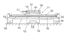
図7及び図8を参照して,基本的構造を有するステージ装置51について説明する。ステージ装置51は,下軸のX軸スライド装置52,上軸のY軸スライド装置55,及びY軸スライド装置55上に配設されるアライメントステージ装置となる回転方向であるθ軸のθ軸ステージ58から構成されたXYθステージ装置である。X軸スライド装置52及びY軸スライド装置55は,例えば,可動コイル型リニアモータ(図示せず)を内蔵したものである。ステージ装置51は,ベッド53とベッド53に対して移動自在に設けられた可動テーブル(図示せず)から成るX軸スライド装置52,X軸スライド装置52の上記可動テーブルに直交して配設されたベッド56とベッド56に対して移動自在に設けられた可動テーブル57から成るY軸スライド装置55,及び可動テーブル57に間座59を介して取り付けられたベッド66とベッド66上に回転可能に配設されたターンテーブル67から成るθ軸ステージ58から構成されている。Y軸スライド装置55は,そのベッド56の両端がベース69に配設されたサポート用スライド装置68に間座62を介して固定されている。また,ステージ装置51は,X軸スライド装置52を構成する可動テーブル(図示せず)上に直交して配設されたY軸スライド装置55を構成するベッド56とを互いに連結する基本構造品であるブラケット60を備えている。ブラケット60は,その下面がX軸スライド装置52の可動テーブル54の上面に固定され,且つブラケット60の上面側がY軸スライド装置55のベッド56の下面に固定されている。ブラケット60は,図8に示すように,取付け用孔63,64が形成された矩形形状の平板61に形成されている。
A
この発明の目的は,上記の課題を解決することであり,X軸スライド装置とY軸スライド装置との間に剛性維持のため補強部材となるブラケットを介在させ,ブラケットの軽量化を達成するためその形状を最適化し,ステージ装置の高速高加速運転をブラケットで阻害することなく,Y軸スライド装置のベッドの撓みを可及的に最小限に抑えてY軸スライド装置の可動テーブルの変位を小さくし,それによって高精度化を達成することを特徴とするブラケットを備えたステージ装置を提供することである。 SUMMARY OF THE INVENTION An object of the present invention is to solve the above-described problems, and to achieve a reduction in weight of the bracket by interposing a bracket serving as a reinforcing member for maintaining rigidity between the X-axis slide device and the Y-axis slide device. The shape is optimized, and the Y-axis slide device's movable table's displacement is reduced by minimizing the bed deflection of the Y-axis slide device as much as possible without hindering the high-speed and high-acceleration operation of the stage device. Thus, it is to provide a stage apparatus having a bracket characterized in that high accuracy is achieved.
この発明は,第1ベッド及び前記第1ベッドに対して第1リニアモータによって摺動自在に設けられた第1可動テーブルから構成されたX軸スライド装置,並びに前記X軸スライド装置の前記第1可動テーブルに対して直交して固設された第2ベッド及び前記第2ベッドに対して第2リニアモータによって摺動自在に設けられた第2可動テーブルから構成されたY軸スライド装置を備えたステージ装置において,
前記X軸スライド装置を構成する前記第1可動テーブル,及び前記Y軸スライド装置を構成する前記第2ベッドとにそれぞれ固定されて前記前記第1可動テーブルに対して前記第2ベッドを固設するブラケットを備えており,
前記ブラケットは,外形と断面が移動方向の長さが幅より長く形成された実質的に矩形形状の平板で形成されており,
前記ブラケットは,前記移動方向の長さが前記第2ベッドより短く且つ前記第2可動テーブルより長く形成されており,
前記ブラケットの幅は,前記第1可動テーブルの摺動方向の長さより短く且つ前記第2ベッドの幅と実質的に同一に形成されており,
前記ブラケットは,前記移動方向の両端部が両側部から中央部に向って幅小になる肉抜きされたV字状切欠き部でそれぞれ形成された一対のつの部と,前記両端部における前記つの部間で前記X軸スライド装置の前記第1可動テーブルを取り付けるための取付け面を形成する本体部とから形成されていることを特徴とするブラケットを備えたステージ装置に関する。
The present invention relates to an X-axis slide device comprising a first bed and a first movable table slidably provided with respect to the first bed by a first linear motor, and the first of the X-axis slide device. A Y-axis slide device comprising a second bed fixed orthogonally to the movable table and a second movable table slidably provided to the second bed by a second linear motor is provided. In the stage device,
The second bed is fixed to the first movable table by being respectively fixed to the first movable table constituting the X-axis slide device and the second bed constituting the Y-axis slide device. With brackets,
The bracket is formed of a substantially rectangular flat plate whose outer shape and cross section are formed so that the length in the moving direction is longer than the width.
The bracket is formed such that a length in the moving direction is shorter than the second bed and longer than the second movable table,
The width of the bracket is shorter than the length of the first movable table in the sliding direction and is substantially the same as the width of the second bed;
The bracket includes a pair of portions each formed by a cut V-shaped cutout portion whose width in the moving direction is reduced from both sides toward the center, and the brackets at the both ends. The present invention relates to a stage apparatus provided with a bracket, characterized in that it is formed from a main body part that forms an attachment surface for attaching the first movable table of the X-axis slide device between the parts.
このステージ装置において,前記ブラケットの下面は前記X軸スライド装置の前記第1可動テーブルの上面に固定されており,前記ブラケットの上面は前記Y軸スライド装置の前記第2ベッドの下面に固定されているものである。 In this stage device, the lower surface of the bracket is fixed to the upper surface of the first movable table of the X-axis slide device, and the upper surface of the bracket is fixed to the lower surface of the second bed of the Y-axis slide device. It is what.
また,このステージ装置において,前記X軸スライド装置は,前記第1ベッドに固定された第1軌道レールと前記第1可動テーブルに固定され且つ前記第1軌道レールを往復移動する第1スライダから成る第1直動案内ユニットが介在しており,また,前記Y軸スライド装置は,前記第2ベッドに固定された第2軌道レールと前記第2可動テーブルに固定され且つ前記第2軌道レールを往復移動する第2スライダから成る第2直動案内ユニットが介在しているものである。 Further, in this stage apparatus, the X-axis slide device includes a first track rail fixed to the first bed and a first slider fixed to the first movable table and reciprocatingly moving on the first track rail. A first linear guide unit is interposed, and the Y-axis slide device is fixed to the second track rail fixed to the second bed and the second movable table, and reciprocates between the second track rails. A second linear motion guide unit composed of a moving second slider is interposed.
また,このステージ装置において,前記V字状切欠き部は,前記ブラケットの前記両端部に対称に形成されており,前記X軸スライド装置の前記第1可動テーブルの幅方向両端面に達していないものである。 Further, in this stage device, the V-shaped notch portions are formed symmetrically at the both end portions of the bracket and do not reach both end surfaces in the width direction of the first movable table of the X-axis slide device. Is.
また,このステージ装置は,前記Y軸スライド装置の前記第2可動テーブルには,前記第2可動テーブルに対して回転方向に移動するターンテーブルを備えたθ軸ステージが配設されている。 In this stage apparatus, the second movable table of the Y-axis slide device is provided with a θ-axis stage having a turntable that moves in the rotational direction with respect to the second movable table.
このステージ装置は,前記ブラケットにおける前記つの部と前記本体部との前記両側部には,前記Y軸スライド装置の前記第2ベッドを取り付けるための複数個の第1取付け用孔が前記ブラケットの前記移動方向に沿って形成されており,また,前記ブラケットにおける前記本体部には,前記X軸スライド装置の前記第1可動テーブルを取り付けるための複数個の第2取付け用孔が前記ブラケットの幅方向に沿って形成されているものである。 In the stage device, a plurality of first mounting holes for mounting the second bed of the Y-axis slide device are formed on both side portions of the one portion and the main body portion of the bracket. A plurality of second mounting holes for mounting the first movable table of the X-axis slide device are formed in the bracket body in the width direction of the bracket. It is formed along.
このステージ装置は,前記ブラケットの前記本体部には,前記ブラケットを軽量にするための少なくとも1個の貫通孔が形成されており,前記貫通孔は,前記本体部に形成された前記第2取付け用孔間に形成されているものである。 The stage apparatus, the main body portion of the bracket, the bracket being at least one through hole is formed to the light, said through hole, said second attachment formed in the body portion are those formed between use hole.
また,前記ブラケットは,前記両端部の前記つの部の前記移動方向の長さが前記本体部の前記移動方向の長さに実質的に同一になるように形成されている。更に,前記ブラケットの全長は,前記Y軸スライド装置の前記第2可動テーブルの移動ストロークより長く形成されている。また,前記ブラケットは,アルミニウム合金製であり,表面にアルマイト被覆層で覆われているものである。 In addition, the bracket is formed such that the length in the moving direction of the one portion at both ends is substantially the same as the length in the moving direction of the main body portion. Furthermore, the overall length of the bracket is longer than the moving stroke of the second movable table of the Y-axis slide device. The bracket is made of an aluminum alloy and is covered with an alumite coating layer on the surface.
この発明によるブラケットを備えたステージ装置は,上記のように,X軸スライド装置とY軸スライド装置との間で剛性を維持する補強部材となるブラケットを介在させ,ブラケットの軽量化を達成するため,ブラケットの形状を最適化して,軽量化してブラケットによるステージ装置の高速高加速運転を阻害することなく,X軸スライド装置上に配設されたY軸スライド装置のベッドの撓みを小さく抑えて,Y軸スライド装置の可動テーブルの変位量を小さくし,それによってステージ装置の高精度化を達成することができる。また,このステージ装置は,水平置きで,上軸のスライド装置の両端部を支えるためにサポート用のスライド装置を設ける従来構造に対し,下軸のスライド装置に作用する負荷を小さくできるので,リニアモータが可動テーブルを駆動して加減速させるために必要な最大推力を下げることができ,ステージ装置のより高速高加速で稼働できる。また,ブラケットを軽量化することで,Y軸スライド装置やθ軸ステージ等のX軸スライド装置の可動テーブルに搭載される可動部材のイナーシャが小さくなり,加減速させるために必要な最大推力を下げることができ,可動テーブルをより高速高加速で稼働でき,ステージ装置を高速高応答で位置決めが可能になる。また,このステージ装置は,下軸のスライド装置の可動テーブルからオーバーハングした上軸のスライド装置の撓みを効率的に抑え,ステージ装置のY軸スライド装置の可動テーブルの変位を小さく抑えられ,高精度化を達成できる。 As described above, the stage device including the bracket according to the present invention interposes a bracket serving as a reinforcing member for maintaining rigidity between the X-axis slide device and the Y-axis slide device, and achieves weight reduction of the bracket. Optimize the shape of the bracket, reduce the weight and suppress the high-speed high-acceleration operation of the stage device by the bracket, suppress the bed deflection of the Y-axis slide device arranged on the X-axis slide device, It is possible to reduce the amount of displacement of the movable table of the Y-axis slide device, thereby achieving high accuracy of the stage device. In addition, this stage device can be placed horizontally and the load acting on the lower shaft slide device can be reduced compared to the conventional structure in which a slide device for support is provided to support both ends of the upper shaft slide device. The maximum thrust required for the motor to accelerate and decelerate by driving the movable table can be reduced, and the stage device can be operated at higher speed and higher acceleration. In addition, by reducing the weight of the bracket, the inertia of the movable member mounted on the movable table of the X-axis slide device such as the Y-axis slide device or the θ-axis stage is reduced, and the maximum thrust required for acceleration / deceleration is reduced. The movable table can be operated at higher speed and higher acceleration, and the stage device can be positioned at higher speed and higher response. In addition, this stage device efficiently suppresses the deflection of the upper-axis slide device overhanging from the movable table of the lower-axis slide device, and suppresses the displacement of the movable table of the Y-axis slide device of the stage device. Accuracy can be achieved.
以下,図面を参照して,この発明によるブラケットを備えたステージ装置の一実施例について説明する。この発明によるブラケットを備えたステージ装置は,図1〜図3に示すように,多軸ステージ装置1であって,該多軸ステージ装置1は,下軸となる直線であるX軸であるX軸スライド装置2,上軸となる直線であるY軸であるY軸スライド装置5,及びY軸スライド装置5上に配設されるアライメントステージ装置となる回転方向であるθ軸のθ軸ステージ8からXYθステージ装置である。X軸スライド装置2及びY軸スライド装置5は,可動コイル型リニアモータを内蔵したものである。この実施例における多軸ステージ装置1は,少なくとも土台,機台等のベース18(図2,図3参照)に固定されるベッド3(第1ベッド)及びベッド3に対してリニアモータ31(第1リニアモータ)によって摺動自在に設けられた可動テーブル4(第1可動テーブル)から構成されたX軸スライド装置2,並びにX軸スライド装置2の可動テーブル4に直交して配設されたベッド6(第2ベッド)及びベッド6に対してリニアモータ31(第2リニアモータ)によって摺動自在に設けられた可動テーブル7(第2可動テーブル)から構成されたY軸スライド装置5から構成されている。また,X軸スライド装置2において,ベッド3には一対の軌道レール41が隔置して移動方向に延びるように固定され,可動テーブル4にはスライダ42が複数固定され,可動テーブル4がベッド3上を往復移動可能に構成されている。また,Y軸スライド装置5において,ベッド6には一対の軌道レール39が隔置して移動方向に延びるように固定され,可動テーブル7にはスライダ40が配設固定され,可動テーブル7がベッド6上を往復移動可能に構成されている。θ軸ステージ8は,可動テーブル7上に間座9を介してベッド16が固定されており,ベッド16上でターンテーブル17がリニアモータ等の駆動手段で回転可能に配設されている。
An embodiment of a stage apparatus having a bracket according to the present invention will be described below with reference to the drawings. As shown in FIGS. 1 to 3, the stage device including the bracket according to the present invention is a
また,X軸スライド装置2及びY軸スライド装置5には,例えば,図4に示すようなリニアモータ31がそれぞれ設けられている。リニアモータ31は,可動コイル型リニアモータであり,ベッド3,6に多数のマグネット33を取り付けたマグネットヨーク32が配設されており,可動テーブル4,7にコイルモジュールである電機子組立体34が取り付けられている。リニアエンコーダ35は,リニアスケール36とリニアエンコーダ用ヘッド37とから構成されている。ベッド3,6には,リニアスケール36及び原点マーク38が設けられており,また,可動テーブル4,7には,リニアエンコーダ用ヘッド37が取り付けられている。更に,リニアモータ31には,電機子組立体34の往復移動で発生する加熱状態を冷却するため空冷用配管50が配設されている。また,ベッド3は,両端にエンドプレート48をそれぞれ固定しており,エンドプレート48には,可動テーブル4の長手方向移動を規制するストッパ46が取り付けられている。ベッド6は,両端にエンドプレート49をそれぞれ固定しており,エンドプレート49には,可動テーブル7の長手方向移動を規制する一対のストッパ47がそれぞれ取り付けられている。
The
この多軸ステージ装置1は,例えば,装置自体の高さ寸法が約70mm,両方のベッド幅寸法が約170mm,ベッド長さが約700mm,可動テーブルのストロークが330mm,可動テーブル全長が200mmである。また,θ軸は,リニアモータを内蔵したアライメントステージ装置であり,回転テーブルであるターンテーブル17が直径200mm,ターンテーブルの動作角度が280度である。また,多軸ステージ装置1のベース18は,アルミニウム合金製であり,ベース18の大きさが760mm×700mm,XYθステージ装置の高さが183mm,装置全体の高さが約350mmであり,省スペースを求める用途のステージ装置では,ボールねじ駆動よりもリニアモータ駆動の方が好ましいものである。
In this
このステージ装置即ち多軸ステージ装置1は,特に,X軸スライド装置2を構成する可動テーブル4上に直交して配設されたY軸スライド装置5を構成するベッド6とを互いに連結するブラケット10を備えていることに特徴を有するものである。言い換えれば,ブラケット10は,下軸のX軸スライド装置2と上軸のY軸スライド装置5とを連結固定すると共に,Y軸スライド装置5の撓みを抑制するための補強部材として機能するものである。この実施例では,ブラケット10は,下面26側がX軸スライド装置2の可動テーブル4の上面28に固定され,且つブラケット10の上面27側がY軸スライド装置5のベッド6の下面29に固定されている。Y軸スライド装置5の可動テーブル7がX軸スライド装置2の可動テーブル4よりもオーバーハングした位置にある領域には,ブラケット10のつの部12の先端部19側よりも本体部11の根元付近に大きなモーメント荷重が作用することになる。ブラケット10は,アルミニウム合金製であり,その表面にアルマイト被覆層25がアルマイト処理で施されている。
This stage device, that is, the
多軸ステージ装置1に組み込まれたブラケット10は,主として,軽量化と剛性アップとを両立させるために,両者のバランスがとれるように,平等強さの梁の考え方に基づいて形成されている。ここで,平等強さの梁とは,梁のどの断面においても一様な曲げ応力が生じるように曲げモーメントに応じて断面形状を変化させたものを意味する。この実施例では,ブラケット10の長手方向の先端30側の形状を,平等強さの梁の考え方に基づいて最適な断面形状に形成しており,平等強さの梁の考え方に基づくと,ブラケット10の板厚を一定にして幅寸法を変化させる方法が取られている。実施例では,ブラケット10は,外形と断面が移動方向の長さが幅より長く形成された実質的に矩形の薄板状の平板に形成されており,移動方向の長さがベッド6より短く,且つ可動テーブル7より長く形成されており,ブラケット10の幅が可動テーブル4の摺動方向の長さより短く,且つベッド6の幅と実質的に同一に形成されている。
The
この多軸ステージ装置1において,ブラケット10は,特に,図5に示すように,移動方向の両端部19が両側部20から中央部21に向って幅小になる肉抜きされたV字形の切欠き部15で形成された一対のつの部12と,つの部12間でX軸スライド装置2の可動テーブル4を取り付けるための取付け面23を形成する本体部11とから形成されていることを特徴としている。図5は,本発明のブラケットの一実施形態の斜視図(V字形切欠き部付)。ブラケット10の長手方向の先端部30には,略V字形の切欠き部15がそれぞれ形成されている。ブラケット10は,板厚を増やす代わりに,つの部12の先端部19よりも本体部11の根元付近の幅を厚く形成した形状になっている。即ち,ブラケット10の端部19は,V字形に切り欠いて切欠き部15を形成することにより,両側部20の一対のつの部12の合計の幅が本体部11の幅に対して,先端30側から本体部11に向って漸次に幅が大きくなるように形成されている。この実施例では,例えば,ブラケット10は,板厚が30mm,長さが520mm,幅寸法が170mm,略V字形の切欠き部15の開口部44の幅寸法が150mm,略V字形の切欠き部15の先端30のR形状の半径寸法が40mm,また,両R形状の半径中心間の距離が260mmに形成されている。また,ブラケット10は,つの部12の板厚が中央部である本体部11の板厚と同じ板厚に形成されている。
In this
また,切欠き部15は,ブラケット10の両端部19に対称に形成されており,X軸スライド装置2の可動テーブル4の幅方向両端面22に達していないものである。また,Y軸スライド装置5の可動テーブル7には,可動テーブル7に対して回転方向に移動するθ軸ステージ8が配設されている。
Further, the
更に.多軸ステージ装置1は,ブラケット10におけるつの部12と本体部11との両側部20には,Y軸スライド装置5のベッド6を取り付けるための複数個(図5では4個)の取付け用孔14(第1取付け用孔)がブラケット10の移動方向に沿って2列形成されている。また,多軸ステージ装置1は,ブラケット10における本体部11には,X軸スライド装置2の可動テーブル4を取り付けるための複数個(図5では3個)の取付け用孔13(第2取付け用孔)がブラケット10の幅方向に沿って2列形成されている。
Furthermore. The
このステージ装置において,ブラケット10は,一対の両端部19のつの部12の移動方向の長さが本体部11の移動方向の長さに実質的に同一になるように形成されている。
In this stage apparatus, the
更に,ブラケット10の全長は,Y軸スライド装置5の可動テーブル7の移動ストロークより長く形成されている。更に,ブラケット10は,アルミニウム合金製であり,表面にアルマイト被覆層25で覆われている。
Further, the overall length of the
次に,図6を参照して,この発明によるブラケットを備えたステージ装置の別の実施例について説明する。多軸ステージ装置1は,ブラケット10Hの本体部11には,ブラケット10Hを軽量にするための少なくとも1個の貫通孔24が形成されている。更に,ブラケット10Hの本体部11に形成された貫通孔24は,取付け用孔14間に形成されている。実施例では,ブラケット10Hの長手方向である移動方向の中央位置の本体部11を軽量化するため,肉抜き用の円形の貫通孔24が形成されている。貫通孔24は,本体部11の中央部に位置しており,ブラケット10Hに作用する曲げモーメントによって発生する応力がほとんど作用しない位置に形成されており,ブラケット10Hに作用する曲げモーメントには影響を及ぼさず,ブラケット10の幅を考慮する必要が無い領域に形成されている。それによって,ブラケット10Hは,貫通孔24を形成することによって,質量を減らしながら,変位の増加を小さく抑えることが可能になる。
Next, with reference to FIG. 6, another embodiment of a stage apparatus having a bracket according to the present invention will be described. In the
次に,図9及び図10を参照して,XYθステージ装置の多軸ステージ装置1にブラケット10を組み込んだ場合のブラケット10の変形を有限要素法で評価する。図9及び図10ではY軸スライド装置5の形状は,簡略化されている。ここで使用した図5及び図6に示すブラケット10は,厚さが30mmであり,図8に示す基本構造品であるブラケット60よりも,10mmから15mm厚く形成されている。ブラケット60は,平板形状であって,厚さが15mmであり,長さLが520mmである。ここで,図5に示すブラケット10は,略V字形の切欠き部15が形成されており,ブラケット60をブラケット10の平板形状と同じ板厚にした場合に,剛性の点では若干劣ることが明らかであるので,その点を考慮して,図8に示すブラケット60の板厚を15mmと20mm,発明品の板厚を30mmにして解析結果を比較した。また,Y軸スライド装置5の可動テーブル7は,ストロークエンドのベッド6の上面45に設けられたメカストッパ43に接触する位置に置かれている。メカストッパ43に接触した可動テーブル7の中心位置は,X軸スライド装置2の可動テーブル4よりも100mm移動方向にオーバーハングした位置になっている。Y軸スライド装置5の可動テーブル7の変位は,θ軸ステージ8(図9,10では省略)等の10kgの質量が均等に分布している条件で解析している。また,解析条件としては,接触する部品同士は,完全に固定されている状態であるとする。
Next, referring to FIGS. 9 and 10, the deformation of the
図10には,XYθステージ装置のブラケット10,10H,60の長さを変化させて,Y軸スライド装置5の全体と,Y軸スライド装置5の可動テーブル7の変位量が解析された状態が示されている。図10に示す変位倍率は,5000倍にしている。また,解析結果は,ブラケットを設けた場合の軽量化と剛性の維持を効率よく達成しているか判定するための参考値である。
主な解析条件は,次のとおり。
Y軸スライド装置5の解析上の質量は,17.3kgである。
Y軸スライド装置5の可動テーブル7の質量は,4kgである。
θ軸ステージ8の総質量は,6kgである。
Y軸スライド装置5の全体の最大変位の位置Aでの最大変位量δ1 は,ブラケット60であって板厚が15mmの場合には,例えば,5.3μmであり,また,可動テーブル7上の最大変位の位置Bでの最大変位量δ2 は,例えば,4.1μmであった。これらの結果については,それぞれに条件に応じて得た結果は,図11〜図14にそれぞれ示されている。
FIG. 10 shows a state in which the lengths of the
The main analysis conditions are as follows.
The analytical mass of the Y-
The mass of the movable table 7 of the Y-
The total mass of the θ-
The maximum displacement amount δ 1 at the position A of the entire maximum displacement of the Y-
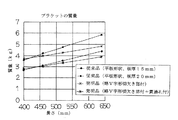
図11には,ブラケット10,10H,60の長さL(mm)と,Y軸スライド装置5の全体の最大変位δ1 との関係を示すグラフである。Y軸スライド装置5のベッド6の最大変位量δ1 は,例えば,印◆が5.3μmである。図11のグラフにおいて,印◆は図8に示す平板状のブラケット60であって板厚が15mmであり,印■は図8に示す平板状のブラケット60であって板厚が20mmであり,印×は図5に示す両端部19に切欠き部15が形成されたブラケット10であって板厚30mmであり,また,印*は図6に示す両端部19に切欠き部15と貫通孔24が形成されたブラケット10Hであって板厚30mmである。本願発明品のブラケット10,10Hは,平板のブラケット10と対比して,ベッド6の変位量δ1 が若干低下するものの実質的に同等であり,十分な剛性を備えているので,切欠き部15,又は切欠き部15と貫通孔24の質量分だけ軽量化に寄与することになる。
FIG. 11 is a graph showing the relationship between the length L (mm) of the
図12には,ブラケット10,10H,60の長さと,Y軸スライド装置5の可動テーブル7の最大変位の関係を示すグラフである。Y軸スライド装置5の可動テーブル7の最大変位量δ2 は,例えば,印◆が4.1μmである。可動テーブル7の最大変位量δ2 は,ブラケット長さLが520mm以上の場合に,変位の変化はほとんどない。ブラケット長さLを短くした場合,400mmまでであれば,変位の増加は抑えられている。図12のグラフにおいて,印◆,印■,印×,及び印*は図11のグラフに示すものと同等である。
FIG. 12 is a graph showing the relationship between the lengths of the
図13は,ブラケット10,10H,60の長さLと質量の関係を示すグラフである。ブラケット長さLが400mmでは,板厚15mmの平板形状のブラケットの方が軽量だが,約440mm以上に長くなると逆転して,図5及び図6に示す本発明品であるブラケット10,10Hの方が軽量になる。また,ブラケット全長が520mmの場合には,図7に示す平板形状のブラケット60は,板厚が15mmの時は質量が3.55kg,板厚が20mmの時は質量が4.74kgであり,図5及び図6に示す本発明品の略V字形切欠き部+貫通孔付は,質量が3.36kgとなり,板厚が20mmの基本構造品(従来品)の71%まで軽量化できている。図13のグラフにおいて,印◆,印■,印×,及び印*は,図11及び図12のグラフに示すものと同等である。
FIG. 13 is a graph showing the relationship between the length L of the
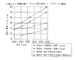
図14は,ブラケット10,10H,60がより軽い構造で変位を抑える効率を確認するグラフである。即ち,「ブラケットの長さ」に対する「Y軸スライド装置5の可動テーブル7上の最大変位量の値」×「ブラケットの質量の値」の関係が示されている。図14のグラフにおいて,印◆,印■,印×,及び印*は,図11〜図13のグラフに示すものと同等である。図14では,値が小さいほど,ブラケット10,10H,60は,軽量で効率よく可動テーブル7の変位量を小さく抑えることを意味している。
FIG. 14 is a graph for confirming the efficiency of suppressing the displacement with a lighter structure of the
次に,ブラケット全長が520mmの場合におけるブラケット10,10H,60を比較する。
ブラケット60は,板厚が20mmの平板形状ブラケットである。
ブラケット10Hは,板厚が30mmであり,両端部19に略V字形切欠き部15が形成されており,本体部11に貫通孔24が形成されているブラケットである。
ブラケット10Hとブラケット60とを比較すると,ブラケット60が質量が4.74kgであり,変位量が4.3μmであった。これに対して,ブラケット10Hは,ブラケット10Hの質量が3.36kgであり,変位量が4.0μmであった。
ここで,ブラケット60を100%とすると,ブラケット10Hは質量が71%,変位量が93%になり,明らかに軽量化と剛性を両立できたことが解る。
また,ブラケット10Hとブラケット60とを「Y軸スライド装置の可動テーブル上の最大変位の値」×「ブラケットの質量」の値で比較すると,ブラケット10Hは66%になる。ブラケット10Hは,軽量で効率よく可動テーブル7の変位を抑えることができることが明らかである。
Next, the
The
The
When the
Here, assuming that the
Further, when the
次に,ブラケットの軽量化の効果を示す試算の条件とその結果を表1に示す。 Next, Table 1 shows the conditions and results of trial calculation showing the effect of reducing the weight of the bracket.

表1において,ブラケットに対する試算は,本発明品としては,略V字形切欠き部15と貫通孔24が形成されたブラケット10Hを用い,また,基本構造品としては,平板形状のブラケット60を用い,これらのブラケット10H,60を組み込んだテーブルを,リニアモータによってある運転パターンを指定回数だけ動かすのに必要な時間の差を求めている。
テーブルを駆動させる時,加減速時には大きな推力が必要になり,テーブルに大きな推力を得るために稼働するリニアモータは発熱する。リニアモータの定格推力が実効推力より大きければ,リニアモータの発熱を抑えることができ,連続運転ができる。ここで,リニアモータの定格推力は,リニアモータが過熱や焼付きを起こさずに,連続して性能を発揮できる使用限界である。また,実効推力は,ある運転パターンのサイクル内で必要な推力を平均化したものである。運転パターンを検討する時は,テーブルを加速させるのに必要な推力Fpから限界加速時間を求め,実効推力Frmsが定格推力よりも大きくならないように加減速時間ta,tbを求める。
試算の運転パターンは,1サイクルが加速,減速,及び停止の位置決め動作であって,定速域が無いものである。
図15は,表1の条件によるテーブルの運転パターンを示す線図であり,1サイクルを符合tで示している。
平均的なステージ装置の稼働時間を想定して,1日の稼働時間を約10時間と仮定し,この運転パターンを15000サイクル動かす場合を仮定している。
基本構造品は,本発明品よりも積載質量mが大きいため,リニアモータを駆動させる時に,発生する熱が多くなる。
表1に示す試算は,本発明品と基本構造品との運転パターンの実効推力Frmsが同じ100Nになるように,加減速時間ta,tbと停止時間tdとを調整している。
ブラケット10H,60の全長は両者とも520mmであり,ブラケット10Hの板厚は30mmであり,ブラケット60の板厚は22.5mmである。可動テーブル上の最大変位は,例えば,3μmになる。
In Table 1, a trial calculation for the bracket uses a
When driving the table, a large thrust is required during acceleration and deceleration, and the linear motor that operates to obtain a large thrust on the table generates heat. If the rated thrust of the linear motor is greater than the effective thrust, heat generation of the linear motor can be suppressed and continuous operation can be achieved. Here, the rated thrust of a linear motor is the limit of use at which the linear motor can continuously perform without causing overheating or seizure. The effective thrust is the average of the required thrust within a certain operating pattern cycle. When examining the operation pattern, the limit acceleration time is obtained from the thrust Fp required to accelerate the table, and the acceleration / deceleration times ta and tb are obtained so that the effective thrust Frms does not become larger than the rated thrust.
The estimated operation pattern is a positioning operation in which one cycle is acceleration, deceleration, and stop, and there is no constant speed range.
FIG. 15 is a diagram showing an operation pattern of the table under the conditions of Table 1, and one cycle is indicated by a symbol t.
Assuming an average stage device operating time, the daily operating time is assumed to be about 10 hours, and this operation pattern is assumed to move 15000 cycles.
Since the basic structure product has a larger loading mass m than the product of the present invention, more heat is generated when the linear motor is driven.
In the trial calculation shown in Table 1, the acceleration / deceleration times ta and tb and the stop time td are adjusted so that the effective thrust Frms of the operation pattern of the product of the present invention and the basic structure product is the same 100N.
Both the
ここで,試算の条件としては,XYθステージ装置の下軸となるX軸スライド装置2を駆動させ,その時のX軸スライド装置2の可動テーブル4に搭載する質量は,本発明品のブラケット10Hを組み込んだテーブルが27.7kgであり,基本構造品のブラケット60を組み込んだテーブルが29.6kgである。
表1に示すように,本発明品のブラケット10Hを組み込んだテーブルは,基本構造品のブラケット60を組み込んだテーブルに比較して,最高速度Vmaxが大きく,加減速時間ta,tbと停止時間tdとが短く,基本構造品のブラケット60に比べて,表1及び図15の運転パターンを15000サイクル動かす運転動作に必要な時間Tを18分短縮することができた。従って,本発明品のブラケット10HをXYθステージ装置等の組立装置に適用すれば,より加減速度を高めて高タクトで稼働できる。即ち,本発明品のブラケット10Hが軽量化の特性を発揮しているといえる。
Here, as a condition for the trial calculation, the
As shown in Table 1, the table incorporating the
この発明によるブラケットを備えたステージ装置は,半導体製造装置,精密機械,測定・検査装置,医療機器,各種ロボット,各種組立装置,搬送機械,工作機械,マイクロマシーン等の各種装置に組み込んで利用して好ましいものである。 The stage device provided with the bracket according to the present invention is incorporated into various devices such as semiconductor manufacturing devices, precision machines, measuring / inspection devices, medical equipment, various robots, various assembling devices, transfer machines, machine tools, and micromachines. It is preferable.
1 多軸ステージ装置
2 X軸スライド装置
3 ベッド(第1ベッド)
4 可動テーブル(第1可動テーブル)
5 Y軸スライド装置
6 ベッド(第2ベッド)
7 可動テーブル(第2可動テーブル)
8 θ軸ステージ
10 ブラケット
11 本体部
12 つの部
13,14 取付け用孔
15 切欠き部
17 ターンテーブル
19 端部
20 側部
21 中央部
22 端面
23 取付け面
24 貫通孔
25 アルマイト被覆層
26,29 下面
27,28 上面
31 リニアモータ
39,41 軌道レール
40,42 スライダ
L ブラケットの長さ
1
4 Movable table (first movable table)
5 Y-
7 Movable table (second movable table)
8 θ-
Claims (11)
前記X軸スライド装置を構成する前記第1可動テーブル,及び前記Y軸スライド装置を構成する前記第2ベッドとにそれぞれ固定されて前記第1可動テーブルに対して前記第2ベッドを固設するブラケットを備えており,
前記ブラケットは,外形と断面が移動方向の長さが幅より長く形成された実質的に矩形形状の平板で形成されており,
前記ブラケットは,前記移動方向の長さが前記第2ベッドより短く且つ前記第2可動テーブルより長く形成されており,
前記ブラケットの幅は,前記第1可動テーブルの摺動方向の長さより短く且つ前記第2ベッドの幅と実質的に同一に形成されており,
前記ブラケットは,前記移動方向の両端部が両側部から中央部に向って幅小になる肉抜きされたV字状切欠き部でそれぞれ形成された一対のつの部と,前記両端部における前記つの部間で前記X軸スライド装置の前記第1可動テーブルを取り付けるための取付け面を形成する本体部とから形成されていることを特徴とするブラケットを備えたステージ装置。 An X-axis slide device comprising a first bed and a first movable table slidably provided by a first linear motor relative to the first bed, and the first movable table of the X-axis slide device A stage device comprising a Y-axis slide device composed of a second bed fixed orthogonally and a second movable table slidably provided to the second bed by a second linear motor;
A bracket that is fixed to the first movable table constituting the X-axis slide device and the second bed constituting the Y-axis slide device, and the second bed is fixed to the first movable table. With
The bracket is formed of a substantially rectangular flat plate whose outer shape and cross section are formed so that the length in the moving direction is longer than the width.
The bracket is formed such that a length in the moving direction is shorter than the second bed and longer than the second movable table,
The width of the bracket is shorter than the length of the first movable table in the sliding direction and is substantially the same as the width of the second bed;
The bracket includes a pair of portions each formed by a cut V-shaped cutout portion whose width in the moving direction is reduced from both sides toward the center, and the brackets at the both ends. A stage device comprising a bracket, wherein the stage device is formed from a main body portion that forms an attachment surface for attaching the first movable table of the X-axis slide device between the portions.
Priority Applications (1)
| Application Number | Priority Date | Filing Date | Title |
|---|---|---|---|
| JP2014036470A JP6355938B2 (en) | 2014-02-27 | 2014-02-27 | Stage device with bracket |
Applications Claiming Priority (1)
| Application Number | Priority Date | Filing Date | Title |
|---|---|---|---|
| JP2014036470A JP6355938B2 (en) | 2014-02-27 | 2014-02-27 | Stage device with bracket |
Publications (3)
| Publication Number | Publication Date |
|---|---|
| JP2015162956A JP2015162956A (en) | 2015-09-07 |
| JP2015162956A5 JP2015162956A5 (en) | 2017-03-23 |
| JP6355938B2 true JP6355938B2 (en) | 2018-07-11 |
Family
ID=54185730
Family Applications (1)
| Application Number | Title | Priority Date | Filing Date |
|---|---|---|---|
| JP2014036470A Active JP6355938B2 (en) | 2014-02-27 | 2014-02-27 | Stage device with bracket |
Country Status (1)
| Country | Link |
|---|---|
| JP (1) | JP6355938B2 (en) |
Cited By (1)
| Publication number | Priority date | Publication date | Assignee | Title |
|---|---|---|---|---|
| WO2022171864A1 (en) * | 2021-02-14 | 2022-08-18 | Inventus Engineering Gmbh | Guidance system for two-axis guidance of a movement and input system |
Family Cites Families (3)
| Publication number | Priority date | Publication date | Assignee | Title |
|---|---|---|---|---|
| JP2002359961A (en) * | 2001-06-01 | 2002-12-13 | Hitachi Metals Ltd | Linear motor and stage apparatus |
| JPWO2006129534A1 (en) * | 2005-05-30 | 2008-12-25 | Thk株式会社 | XY guidance device |
| JP3923997B1 (en) * | 2006-06-30 | 2007-06-06 | 株式会社ミラック光学 | General-purpose dovetail sliding unit |
-
2014
- 2014-02-27 JP JP2014036470A patent/JP6355938B2/en active Active
Cited By (1)
| Publication number | Priority date | Publication date | Assignee | Title |
|---|---|---|---|---|
| WO2022171864A1 (en) * | 2021-02-14 | 2022-08-18 | Inventus Engineering Gmbh | Guidance system for two-axis guidance of a movement and input system |
Also Published As
| Publication number | Publication date |
|---|---|
| JP2015162956A (en) | 2015-09-07 |
Similar Documents
| Publication | Publication Date | Title |
|---|---|---|
| TWI310328B (en) | Gantry positioning system | |
| JP4259978B2 (en) | Linear motor actuator | |
| CN105485481B (en) | A kind of displacement adjustable accurate locating platform | |
| EP1637277A1 (en) | Parallel kinematics machine with elastic joints | |
| JP4072551B2 (en) | Processing equipment | |
| JP6355938B2 (en) | Stage device with bracket | |
| JP4328575B2 (en) | Positioning mechanism using vibration type drive | |
| JP6740088B2 (en) | Linear motor | |
| EP1246350B1 (en) | Linear driving device | |
| EP3246614B1 (en) | Movable table system | |
| JP6236298B2 (en) | Vertical axis slide device with built-in moving coil linear motor | |
| JP2013153058A (en) | Mounting head and component mounting apparatus including the same | |
| JP6086824B2 (en) | Drive stage and component mounting apparatus using drive stage | |
| JP6006739B2 (en) | Reciprocating motion test apparatus, reciprocating motion test method and program | |
| JP7290815B2 (en) | Linear motor drive device and surface shape measuring device | |
| JP5696402B2 (en) | Actuator | |
| JP4450674B2 (en) | Parts holding device | |
| JP2011238887A (en) | Component mounting device and maintenance method | |
| JP6535172B2 (en) | Vertical shaft slide device incorporating a moving coil type linear motor | |
| CN205331721U (en) | Adjustable precision positioning platform of displacement | |
| JP3793871B2 (en) | Stage equipment | |
| TWI678253B (en) | Flexible mechanism | |
| KR101479954B1 (en) | Open-frame stage | |
| CN110270788B (en) | High-speed precise wire welding platform and control method thereof | |
| JP3721969B2 (en) | Stage equipment |
Legal Events
| Date | Code | Title | Description |
|---|---|---|---|
| A521 | Request for written amendment filed |
Free format text: JAPANESE INTERMEDIATE CODE: A523 Effective date: 20170217 |
|
| A621 | Written request for application examination |
Free format text: JAPANESE INTERMEDIATE CODE: A621 Effective date: 20170217 |
|
| A977 | Report on retrieval |
Free format text: JAPANESE INTERMEDIATE CODE: A971007 Effective date: 20171018 |
|
| A131 | Notification of reasons for refusal |
Free format text: JAPANESE INTERMEDIATE CODE: A131 Effective date: 20171031 |
|
| A521 | Request for written amendment filed |
Free format text: JAPANESE INTERMEDIATE CODE: A523 Effective date: 20171201 |
|
| TRDD | Decision of grant or rejection written | ||
| A01 | Written decision to grant a patent or to grant a registration (utility model) |
Free format text: JAPANESE INTERMEDIATE CODE: A01 Effective date: 20180605 |
|
| A61 | First payment of annual fees (during grant procedure) |
Free format text: JAPANESE INTERMEDIATE CODE: A61 Effective date: 20180613 |
|
| R150 | Certificate of patent or registration of utility model |
Ref document number: 6355938 Country of ref document: JP Free format text: JAPANESE INTERMEDIATE CODE: R150 |
|
| R250 | Receipt of annual fees |
Free format text: JAPANESE INTERMEDIATE CODE: R250 |
|
| R250 | Receipt of annual fees |
Free format text: JAPANESE INTERMEDIATE CODE: R250 |