JP6346167B2 - Analog measurement scanning method in machine tools and corresponding machine tool apparatus - Google Patents
Analog measurement scanning method in machine tools and corresponding machine tool apparatus Download PDFInfo
- Publication number
- JP6346167B2 JP6346167B2 JP2015506298A JP2015506298A JP6346167B2 JP 6346167 B2 JP6346167 B2 JP 6346167B2 JP 2015506298 A JP2015506298 A JP 2015506298A JP 2015506298 A JP2015506298 A JP 2015506298A JP 6346167 B2 JP6346167 B2 JP 6346167B2
- Authority
- JP
- Japan
- Prior art keywords
- traverse
- probe
- analog
- measurement
- machine tool
- Prior art date
- Legal status (The legal status is an assumption and is not a legal conclusion. Google has not performed a legal analysis and makes no representation as to the accuracy of the status listed.)
- Active
Links
Images


Classifications
-
- G—PHYSICS
- G01—MEASURING; TESTING
- G01B—MEASURING LENGTH, THICKNESS OR SIMILAR LINEAR DIMENSIONS; MEASURING ANGLES; MEASURING AREAS; MEASURING IRREGULARITIES OF SURFACES OR CONTOURS
- G01B21/00—Measuring arrangements or details thereof, where the measuring technique is not covered by the other groups of this subclass, unspecified or not relevant
- G01B21/02—Measuring arrangements or details thereof, where the measuring technique is not covered by the other groups of this subclass, unspecified or not relevant for measuring length, width, or thickness
- G01B21/04—Measuring arrangements or details thereof, where the measuring technique is not covered by the other groups of this subclass, unspecified or not relevant for measuring length, width, or thickness by measuring coordinates of points
- G01B21/045—Correction of measurements
-
- G—PHYSICS
- G01—MEASURING; TESTING
- G01B—MEASURING LENGTH, THICKNESS OR SIMILAR LINEAR DIMENSIONS; MEASURING ANGLES; MEASURING AREAS; MEASURING IRREGULARITIES OF SURFACES OR CONTOURS
- G01B5/00—Measuring arrangements characterised by the use of mechanical techniques
- G01B5/004—Measuring arrangements characterised by the use of mechanical techniques for measuring coordinates of points
- G01B5/008—Measuring arrangements characterised by the use of mechanical techniques for measuring coordinates of points using coordinate measuring machines
-
- G—PHYSICS
- G01—MEASURING; TESTING
- G01B—MEASURING LENGTH, THICKNESS OR SIMILAR LINEAR DIMENSIONS; MEASURING ANGLES; MEASURING AREAS; MEASURING IRREGULARITIES OF SURFACES OR CONTOURS
- G01B7/00—Measuring arrangements characterised by the use of electric or magnetic techniques
- G01B7/004—Measuring arrangements characterised by the use of electric or magnetic techniques for measuring coordinates of points
- G01B7/008—Measuring arrangements characterised by the use of electric or magnetic techniques for measuring coordinates of points using coordinate measuring machines
-
- G—PHYSICS
- G05—CONTROLLING; REGULATING
- G05B—CONTROL OR REGULATING SYSTEMS IN GENERAL; FUNCTIONAL ELEMENTS OF SUCH SYSTEMS; MONITORING OR TESTING ARRANGEMENTS FOR SUCH SYSTEMS OR ELEMENTS
- G05B19/00—Programme-control systems
- G05B19/02—Programme-control systems electric
- G05B19/18—Numerical control [NC], i.e. automatically operating machines, in particular machine tools, e.g. in a manufacturing environment, so as to execute positioning, movement or co-ordinated operations by means of programme data in numerical form
- G05B19/401—Numerical control [NC], i.e. automatically operating machines, in particular machine tools, e.g. in a manufacturing environment, so as to execute positioning, movement or co-ordinated operations by means of programme data in numerical form characterised by control arrangements for measuring, e.g. calibration and initialisation, measuring workpiece for machining purposes
Description
本発明は、アーチファクトを測定する方法に関し、特に工作機械上に取り付けられたアナログ測定ツールを使用してアーチファクトを走査する方法に関する。 The present invention relates to a method for measuring artifacts, and more particularly to a method for scanning artifacts using an analog measurement tool mounted on a machine tool.
工作物に対して移動させるために工作機械スピンドルに測定プローブを取り付けることにより、工作物を測定することが知られている。特に、典型的には、このプローブは、例えば特許文献1に記載されるような、プローブのスタイラスが工作物表面に接触するときにトリガ信号を生成するタッチトリガプローブであった。このトリガ信号は、工作機械の数値制御装置(NC)のいわゆる「スキップ」入力に送られる。これに応答して、対象および工作物の相対移動が、停止され、制御装置は、マシンの位置(すなわち、マシンに対するスピンドルおよびプローブの位置)を即座に読み取る。これは、マシンの移動用のサーボ制御ループに位置フィードバック情報を提供するエンコーダなどのマシンの測定デバイスから得られる。かかるシステムを使用する欠点は、測定プロセスが比較的遅く、その結果として、多数の測定点が必要とされる場合に測定時間が長くなる点である。 It is known to measure a workpiece by attaching a measurement probe to the machine tool spindle for movement relative to the workpiece. In particular, the probe is typically a touch trigger probe that generates a trigger signal when the probe stylus contacts the workpiece surface, as described, for example, in US Pat. This trigger signal is sent to the so-called “skip” input of the numerical controller (NC) of the machine tool. In response, the relative movement of the object and workpiece is stopped and the controller immediately reads the machine position (ie, the position of the spindle and probe relative to the machine). This is obtained from a machine measurement device such as an encoder that provides position feedback information to a servo control loop for machine movement. The disadvantage of using such a system is that the measurement process is relatively slow and, as a result, the measurement time is increased when a large number of measurement points are required.
また、アナログ測定プローブ(走査プローブとしても一般的に知られる)が、知られている。典型的には、コンタクトアナログプローブは、工作物表面に接触するためのスタイラスと、プローブ本体に対するスタイラスの偏向を測定するプローブ内のトランスデューサとを備える。一例が、特許文献2に示されている。使用時に、アナログプローブは、工作物の表面に対して移動され、それにより、スタイラスは、この表面を走査し、プローブトランスデューサの出力の継続的な読取りが行われる。プローブ検出出力とマシン位置出力とを組み合わせることにより、座標データを取得することが可能となり、これにより、この走査全体にわたる非常に多数の点において工作物表面の位置を判明させることが可能となる。したがって、アナログプローブは、タッチトリガプローブを使用して実際に可能となるものよりも、工作物表面の形状のより詳細な測定値の取得を可能にする。
Analog measurement probes (also commonly known as scanning probes) are also known. Typically, a contact analog probe comprises a stylus for contacting the workpiece surface and a transducer in the probe that measures the stylus deflection relative to the probe body. An example is shown in
理解されるように(および図2との関連において以下でさらに詳細に説明されるように)、アナログプローブは、測定範囲が限定される。さらに、アナログプローブは、好ましい測定範囲を有する場合がある。アナログプローブは、その好ましい測定範囲外のデータを取得することが可能である場合があるが、この範囲外から取得されたデータは、例えば好ましい測定範囲内で取得されたデータよりも精度が低いことが考えられ得ることなどにより、あまり好ましいものではない可能性がある。好ましい測定範囲の境界は、プローブのタイプ、利用される較正ルーチン、およびさらには例えば測定される対象を含む、多数の異なる要素に応じて変化し得る。多くの状況においては、アナログプローブが、工作物の表面に沿って走査する際に、その好ましい測定範囲内に維持されるように確保することが好ましいこととなり得る。コンタクトアナログプローブの好ましい測定範囲は、例えば任意の所与の次元において+/−0.8mm以下であり、例えばいくつかの状況においては任意の所与の次元において+/−0.3mmの小ささであり得る。(これらの値は、スタイラスの休止位置から測定され得る)。さらに、実際の好ましい測定範囲は、最小量の偏向が、好ましい測定範囲に到達するために必要とされ得る場合があり得るため、上記に示した数字よりもさらに小さいものとなる恐れがある。したがって、好ましい測定範囲が、休止位置から+/−0.5mmであり得る場合でも、少なくとも第1の+/−0.05mmの偏向または例えば第1の+/−0.1mmの偏向が、好ましい測定範囲内に含まれない場合がある(これもまた、図2に関連して以下でさらに詳細に説明される)。したがって、理解されるように、プローブ/工作物位置関係のリアルタイム管理が、アナログプローブがその好ましい測定範囲外に陥る状況を回避するために、必要とされる。 As will be appreciated (and as described in more detail below in connection with FIG. 2), analog probes have a limited measurement range. Furthermore, the analog probe may have a preferred measurement range. An analog probe may be able to acquire data outside its preferred measurement range, but the data obtained from outside this range is less accurate than, for example, data obtained within the preferred measurement range. May be less preferred, for example. The preferred measurement range boundaries may vary depending on a number of different factors including the type of probe, the calibration routine utilized, and even the object being measured, for example. In many situations it may be preferable to ensure that the analog probe remains within its preferred measurement range as it scans along the surface of the workpiece. A preferred measurement range for a contact analog probe is, for example, less than +/− 0.8 mm in any given dimension, for example, in some situations, as small as +/− 0.3 mm in any given dimension. It can be. (These values can be measured from the rest position of the stylus). Furthermore, the actual preferred measurement range may be even smaller than the numbers given above, since a minimum amount of deflection may be required to reach the preferred measurement range. Thus, even if the preferred measurement range may be +/− 0.5 mm from the rest position, at least a first +/− 0.05 mm deflection or for example a first +/− 0.1 mm deflection is preferred. It may not be included within the measurement range (also described in more detail below in connection with FIG. 2). Therefore, as will be appreciated, real-time management of the probe / workpiece position relationship is required to avoid situations where the analog probe falls outside its preferred measurement range.
これが理由となり、アナログプローブは、アナログプローブ自体が長年にわたり知られているにもかかわらず、典型的には専用座標測定機(CMM)と共にのみ使用されてきた。CMMは、かかるプローブ偏向の管理の実施を可能にするための専用のリアルタイム制御ループを有する。特に、CMMにおいては、工作物に対して測定プローブを移動させるための予め定められた動作経路を規定するプログラムがロードされた、制御装置が用意される。制御装置は、測定プローブの移動を誘発するためにモータを作動させるために使用されるプログラムからモータ制御信号を発生させる。また、制御装置は、マシンのエンコーダからリアルタイム位置データを、またアナログプローブから偏向データ(コンタクトプローブの場合)を受信する。工作物の材料条件の変化に対応するために、専用制御ループ構成が存在する。これは、上述のモータ制御信号および偏向データが送られるフィードバックモジュールを備える。フィードバックモジュールは、論理回路を使用してオフセット制御ベクトルを継続的に更新し(偏向データに基づき)、さらにこのオフセット制御ベクトルは、プログラムから生成された上述のモータ制御信号を調節するために使用され、その後、アナログプローブが工作物を走査する際に好ましい測定範囲内にプローブ偏向を維持しようと試みるためにCMMのモータへと送信される。これは、いずれも1から2ms未満の応答時間で閉ループ制御ループ内において生じる。これは、例えば特許文献3に記載されている。さらに、アナログプローブ自体からのリアルタイムデータを使用するかかるリアルタイム制御ループは、以前にRenishaw(登録商標)plcから入手可能であったCyclone(商標)デジタル化マシンにおいて具現化される。このマシンにおいては、アナログプローブは、予め定められた経路、具体的には未知の対象を含む境界領域中の2Dラスタ経路に倣うように制御された。それが、その経路内において未知のまたは予期しないフィーチャを検出すると、動作速度は、リアルタイム制御が、フィーチャの表面を見失うことなくまたはプローブを過剰偏向させることなく未知のまたは予期しないフィーチャに対してアナログプローブを誘導するために使用され得るように、著しく低減された。さらに、その後は、未知のまたは予期しないフィーチャの存在は、プローブが、後のラスタ走査において未知のまたは予期しないフィーチャの近傍を再び走査する場合には、予測され、それにより、動作速度は、リアルタイム制御による予期しないフィーチャに対するプローブの誘導が可能になるように、低減された。 For this reason, analog probes have typically been used only with dedicated coordinate measuring machines (CMMs), although analog probes themselves have been known for many years. The CMM has a dedicated real-time control loop to allow implementation of such probe deflection management. In particular, in the CMM, a control device loaded with a program that defines a predetermined operation path for moving the measurement probe relative to the workpiece is prepared. The controller generates a motor control signal from a program used to operate the motor to induce movement of the measurement probe. The control device also receives real-time position data from the machine encoder and deflection data (in the case of contact probes) from the analog probe. A dedicated control loop configuration exists to accommodate changes in workpiece material conditions. This comprises a feedback module to which the motor control signal and deflection data described above are sent. The feedback module continuously updates the offset control vector using logic circuitry (based on deflection data), and this offset control vector is used to adjust the motor control signal generated from the program. The analog probe is then sent to the CMM motor to attempt to maintain the probe deflection within the preferred measurement range when scanning the workpiece. This all occurs in a closed loop control loop with a response time of less than 1 to 2 ms. This is described in Patent Document 3, for example. Further, such a real-time control loop using real-time data from the analog probe itself is implemented in a Cyclone ™ digitizing machine that was previously available from Renishaw ™ plc. In this machine, the analog probe was controlled to follow a predetermined path, specifically a 2D raster path in a boundary region containing unknown objects. When it detects an unknown or unexpected feature in its path, the speed of operation is analog to the unknown or unexpected feature without real-time control losing sight of the feature surface or over-deflecting the probe. Significantly reduced so that it can be used to guide the probe. Furthermore, the presence of unknown or unexpected features is then predicted if the probe scans again in the vicinity of unknown or unexpected features in a later raster scan, so that the operating speed is real-time. Reduced to allow probe guidance to unexpected features by control.
プローブ位置決めに対するかかる厳格な制御と、リアルタイムスタイラス偏向データを処理することが可能であることとにより、かかる専用CMMは、それらの予期される形状から逸脱した複雑な物品を走査することが可能となり、さらには未知の形状の物品を走査することが可能となる。 Such strict control over probe positioning and the ability to process real-time stylus deflection data allow such dedicated CMMs to scan complex articles that deviate from their expected shape, Furthermore, it is possible to scan an article having an unknown shape.
今日まで、アナログプローブは、工作機械走査用途に広く使用されてこなかった。これは、CMMにより実現されるアナログプローブのリアルタイム制御を容易化しない、多数の市販の工作機械に固有の特性による。これは、工作機械が、主に工作物を機械加工するために展開され、工作物の測定のためにそれにおいて測定プローブを使用することが、基本的に補足的なものであるからである。したがって、工作機械は、典型的にはアナログ測定プローブからのデータを使用してリアルタイム制御するようには構成されない。実際に、多くの場合には、工作機械の制御装置は、測定プローブから偏向データを直接的に受信するために組み込まれた装備を有さない。むしろ、例えば特許文献4に記載されているように、プローブは、インターフェースと通信する必要があり(例えば無線により)、このインターフェースは、プローブ偏向データを受信し、別個のシステムにこのデータを送り、この別個のシステムが、その後にマシン位置データに偏向データを組み合わせることによって、後に完全な対象測定データを形成する。 To date, analog probes have not been widely used for machine tool scanning applications. This is due to the inherent characteristics of many commercially available machine tools that do not facilitate real-time control of analog probes realized by CMM. This is because it is basically complementary that a machine tool is deployed primarily for machining a workpiece and using a measurement probe therein for measuring the workpiece. Thus, machine tools are typically not configured for real-time control using data from analog measurement probes. Indeed, in many cases, the machine tool controller does not have any built-in equipment to receive deflection data directly from the measurement probe. Rather, as described, for example, in US Pat. No. 6,089,089, the probe needs to communicate with an interface (eg, wirelessly) that receives probe deflection data and sends this data to a separate system, This separate system later forms complete object measurement data later by combining the machine position data with the deflection data.
これにより、既知の対象に関する走査測定データを取得するために工作機械においてアナログプローブを使用することが困難になる。なぜならば、対象の予期される形状からの任意のばらつきが、プローブを過剰偏向させる恐れがあり、したがって測定プロセスを失敗させる恐れがあるからである(一方で、CMMにおいては、プローブの動作経路は、プローブが過剰偏向せぬように確保するのに十分な迅速さで更新され得る)。また、これにより、未知の対象に関する走査測定データを取得するために工作機械においてアナログプローブを使用することが困難になる。なぜならば、これは、プローブの動作経路が、過剰偏向を回避するのに十分な迅速さで更新されることを本質的に必要とするからである。 This makes it difficult to use an analog probe in a machine tool to obtain scan measurement data for a known object. This is because any variation from the expected shape of the object can over-deflect the probe and thus fail the measurement process (while in CMM, the operating path of the probe is And can be updated quickly enough to ensure that the probe does not over-deflate). This also makes it difficult to use an analog probe in a machine tool to obtain scan measurement data for an unknown object. This is because the operating path of the probe essentially requires that it be updated quickly enough to avoid excessive deflection.
工作機械においてアナログ走査プローブを使用する問題点を解消するための技術が、展開されてきた。例えば、プログラム命令がドリップフィード式に工作機械の制御装置にロードされる、ドリップフィード技術が知られている。特に、各命令により、プローブは、わずかな距離(すなわちプローブの好ましい偏向範囲未満)だけ移動され、プローブの出力が、偏向度を判定するために解析され、次いで、これは、制御装置に送るべき次の命令を生成するために使用される。しかし、かかる技術は、CMMにおいてアナログ走査プローブを使用して実施され得る走査技術よりも依然としてはるかに制限される。特に、かかる方法は、非常に低速で非効率である。 Techniques have been developed to eliminate the problems of using analog scanning probes in machine tools. For example, drip feed technology is known in which program instructions are loaded into the machine tool controller in a drip feed fashion. In particular, each command causes the probe to move a small distance (ie less than the preferred deflection range of the probe) and the probe output is analyzed to determine the degree of deflection, which should then be sent to the controller Used to generate the next instruction. However, such techniques are still much more limited than scanning techniques that can be implemented using analog scanning probes in CMM. In particular, such a method is very slow and inefficient.
特許文献5は、第1の測定作業が結果として過剰偏向または過小偏向をもたらす場合に、調節された経路にしたがって測定作業を繰り返すことを伴う、既知の対象を測定するためのプロセスを説明している。 U.S. Patent No. 6,057,051 describes a process for measuring a known object that involves repeating a measurement operation according to a regulated path when the first measurement operation results in over or under deflection. Yes.
また、この問題は、工作機械においてアナログプローブを使用する場合には、さらに悪化し得る。なぜならば、それらの構成(工作機械により提供されるより過酷な環境と、それらが工作機械のスピンドルに/から自動交換される場合などにさらされるより大きな加速および力との中において、それらを使用することを可能にし得る構成)により、それらが、しばしば、例えば任意の所与の次元において+/−0.8mm以下(スタイラスの休止位置から測定される)であり、例えばいくつかの状況においては任意の所与の次元において+/−0.5mm以下であり、例えばいくつかの状況においては任意の所与の次元において+/0.3mm未満であるなど、CMMと共に使用するためのアナログプローブよりもはるかに小さな測定範囲を有するからである。したがって、これは、CMMにおいて使用されるアナログプローブに比べて誤差に対するより小さな余地を与えるものとなり得る。また、上述のように、最小偏向が、好ましい測定範囲に到達するために必要とされる場合がある。 This problem can be exacerbated when analog probes are used in machine tools. Because they use them in their configuration (the more harsh environment provided by the machine tool and the greater acceleration and force they are exposed to when they are automatically exchanged to / from the machine tool spindle, etc. They are often less than +/− 0.8 mm (measured from the rest position of the stylus), for example in any given dimension, for example in some situations More than an analog probe for use with a CMM, such as +/− 0.5 mm or less in any given dimension, eg, less than + / 0.3 mm in any given dimension in some situations. Because it has a much smaller measurement range. This can therefore provide less room for error compared to analog probes used in CMM. Also, as noted above, a minimum deflection may be required to reach the preferred measurement range.
具体的な一例として、測定範囲は、最大偏向0.725mmおよび0.125mmの最小偏向(スタイラスの休止位置から測定される)により規定され得る。したがって、この場合には、これは、表面が、基準値から+/−0.3mmであると共に、正確な測定が維持され得ることを意味し得る。しかし、この数字は、より小さくなる恐れがあり、例えば、表面不確実性が、+/−0.1mmであることが知られており、これは、約+/−0.325mmの最大プローブ偏向および+/−0.125mmの最小プローブ偏向に相当する。 As a specific example, the measurement range may be defined by a maximum deflection of 0.725 mm and a minimum deflection of 0.125 mm (measured from the rest position of the stylus). Thus, in this case, this may mean that the surface is +/− 0.3 mm from the reference value and that an accurate measurement can be maintained. However, this number can be smaller, for example, surface uncertainty is known to be +/− 0.1 mm, which is a maximum probe deflection of about +/− 0.325 mm. And corresponds to a minimum probe deflection of +/− 0.125 mm.
本発明の第1の態様によれば、複数のオフセットトラバースにわたり対象の表面の走査測定データを取得する、工作機械装置上に取り付けられたアナログ測定プローブを使用して、前記表面に関する測定データセットを生成する方法が提供される。後のトラバースが、以前のトラバースからオフセットされることにより、一連のトラバースにわたって、アナログプローブの表面検出領域が、i)前記対象中を側方に、および/またはii)前記対象から離れる方にもしくは前記対象に向かう方に進行し、少なくとも1つの後のトラバースに関する前記対象およびアナログプローブの相対動作経路が、少なくとも1つの以前のトラバースの間に取得されたデータに基づき生成および/または更新される。 According to a first aspect of the present invention, a measurement data set relating to the surface is obtained using an analog measurement probe mounted on a machine tool device for obtaining scanning measurement data of the surface of interest over a plurality of offset traverses. A method of generating is provided. The subsequent traverse is offset from the previous traversal, so that over a series of traversals, the surface detection area of the analog probe is either i) laterally into the object and / or ii) away from the object or Proceeding towards the object, a relative motion path of the object and analog probe for at least one subsequent traverse is generated and / or updated based on data acquired during the at least one previous traverse.
したがって、以前のトラバースから取得された測定データが、後のトラバースに沿った動作経路を判定するために使用され得る。これは、走査測定データを取得する効率を向上させ得る。特に、それは、例えばコンタクトアナログプローブが過剰偏向する(例えば、測定データが(例えば確実には)取得不可能となるおよび/もしくは前記アナログプローブが破損のリスクを負う程度まで、またはその程度を超えるほどにまで)などの、後のトラバース時の望ましくない状況を前記アナログプローブおよび対象が確実に回避するように使用され得る。データが第1の、例えば好ましい測定範囲内において取得されることが好ましい実施形態においては、それは、前記アナログプローブがその好ましい測定範囲を超過する(例えば、その好ましい測定範囲を超えるデータを取得する)のを回避させるのを補助するために使用され得る。いくつかの状況においては、それは、その第1の、例えば好ましい測定範囲内に前記アナログプローブの測定を維持するのを補助するために使用され得る。 Thus, measurement data obtained from a previous traverse can be used to determine an operating path along a subsequent traverse. This can improve the efficiency of acquiring scan measurement data. In particular, for example, the contact analog probe is excessively deflected (eg, to the extent that measurement data cannot (eg reliably) be acquired and / or the analog probe is at risk of damage or beyond) The analog probe and subject can be used to ensure that undesirable situations during subsequent traversal, such as In embodiments where it is preferred that data be acquired within a first, eg, preferred measurement range, it is that the analog probe exceeds its preferred measurement range (eg, obtains data that exceeds its preferred measurement range). Can be used to help avoid this. In some situations, it can be used to help maintain the measurement of the analog probe within its first, eg, preferred measurement range.
理解されるように、アナログプローブの表面検出領域は、前記アナログプローブが前記対象の前記表面を検出し、したがって前記対象に関する測定データを収集し得る、空間内の領域であり得る。理解されるように、これは、プローブごとに異なる。コンタクトプローブの場合には、これは、前記プローブの表面接触部分(例えば、スタイラスを有するアナログプローブのスタイラス先端部)を含み得る。非コンタクトプローブの場合には、それは、前記非コンタクトプローブが表面を感知および測定し得る、空間内の点、領域、または容積であり得る。 As will be appreciated, the surface detection area of an analog probe can be an area in space where the analog probe can detect the surface of the object and thus collect measurement data about the object. As will be appreciated, this varies from probe to probe. In the case of a contact probe, this may include the surface contact portion of the probe (eg, the stylus tip of an analog probe with a stylus). In the case of a non-contact probe, it can be a point, region, or volume in space where the non-contact probe can sense and measure a surface.
理解されるように、トラバースは、前記対象中を相対的にトラバースする表面検出領域を備え得る。これは、前記アナログプローブおよび/または対象を互いに対して移動させることにより実現され得る。例えば、これは、前記アナログプローブおよび/または対象を互いに対して並進的および/または回転的に移動させることにより実現され得る。したがって、トラバースは、表面検出領域が前記対象をトラバースするように、相対動作経路にしたがって前記アナログプローブおよび/または対象を制御することを含み得る。 As will be appreciated, the traverse may comprise a surface detection region that traverses relatively within the object. This can be achieved by moving the analog probe and / or the object relative to each other. For example, this may be achieved by moving the analog probes and / or objects in translation and / or rotation relative to each other. Thus, traversing may include controlling the analog probe and / or object according to a relative motion path such that a surface detection region traverses the object.
理解されるように、相対動作経路を規定するプログラムにしたがって前記アナログプローブおよび対象を相対的に移動させるために前記工作機械を制御し得る、制御装置が用意され得る。前記方法は、複数のオフセットトラバースを規定する予め定められた動作経路を前記工作機械の制御装置にロードすることを含み得る。この場合に、少なくとも1つの後のトラバースに関する前記相対動作経路は、少なくとも1つの以前のトラバースの間に取得されたデータに基づき前記後のトラバースに関する予め定められた動作経路を変更することによって生成および/または更新され得る。理解されるように、別の実施形態においては、各トラバースに関する動作経路が、「実行中に」すなわち必要に応じておよび必要時に生成されるということがあり得る。したがって、前記方法は、第1のトラバースに関する動作経路にロードすることを含み得ると共に、後のトラバースに関する動作経路は、第1のトラバースの実行中または実行後に、および例えば第1のトラバースの間に取得されたデータに基づき、生成される(および/または前記制御装置にロードされる)。 As will be appreciated, a controller can be provided that can control the machine tool to move the analog probe and object relative to each other according to a program that defines a relative motion path. The method may include loading a predetermined motion path defining a plurality of offset traverses into the machine tool controller. In this case, the relative motion path for at least one subsequent traverse is generated and modified by changing a predetermined motion path for the subsequent traverse based on data acquired during at least one previous traverse. / Or may be updated. As will be appreciated, in another embodiment, an operational path for each traverse may be generated “on the fly”, ie as needed and as needed. Accordingly, the method may include loading into an operational path for a first traverse and an operational path for a subsequent traverse may be during or after execution of the first traverse and during, for example, the first traverse. Based on the acquired data, it is generated (and / or loaded into the controller).
前記少なくとも1つの後のトラバースに関する動作経路を更新することは、動作経路を規定する前記制御装置にロードされたプログラムを変更することを含み得る。動作経路の更新は、新規の動作経路を規定する新規のプログラムを生成することを含み得る。動作経路の更新は、前記工作機械の制御装置に前記新規のプログラムをロードすることを含み得る。前記新規のプログラムは、前記工作機械の制御装置とは別個の処理デバイス(例えばPC)において生成され得る。前記プログラムの変更は、前記制御装置に既にロードされた予め定められたプログラムを修正することを含み得る。これは、前記制御装置にロードすべき新規のプログラムを生成するよりもはるかに迅速かつ効率的であり得る。 Updating the operational path for the at least one subsequent traverse may include changing a program loaded on the controller that defines the operational path. Updating the operation path may include generating a new program that defines the new operation path. The operation path update may include loading the new program into the machine tool controller. The new program may be generated in a processing device (for example, a PC) separate from the machine tool controller. The program change may include modifying a predetermined program already loaded on the controller. This can be much quicker and more efficient than generating a new program to be loaded into the controller.
動作経路を更新することは、任意には、前記プログラムにより参照されるデータを変更することを含み得る(前記プログラムの変更に加えてまたはその代替として)。これは、前記制御装置にロードされた前記プログラムにより参照される少なくとも1つの変数を変更することを含み得る。前記変数は、前記プログラムの一部か、または前記プログラムとは別個であるが関連付けられた変数表の一部であることが可能であり、例えば前記制御装置に格納され得る。これは、動作経路を変更する特に迅速かつ効率的な方法である。前記変数は、後々の前記プローブの一部とフィーチャの予期される表面との間の基準オフセット距離に関するものであり得る。例えば、それは、前記対象の予期される表面からの、プローブ先端部中心の基準オフセットに関するものであり得る。 Updating the operating path may optionally include changing data referenced by the program (in addition to or as an alternative to changing the program). This may include changing at least one variable referenced by the program loaded into the controller. The variable can be part of the program or part of a variable table that is separate from but associated with the program and can be stored, for example, in the controller. This is a particularly quick and efficient way of changing the operating path. The variable may relate to a reference offset distance between a later portion of the probe and the expected surface of the feature. For example, it may relate to a reference offset of the probe tip center from the expected surface of the object.
前記少なくとも1つの後のトラバースは、前記対象とアナログプローブとの不利な位置関係を回避するために更新され得る。理解されるように、不利な位置関係と見なされるものは、個々の状況に応じて決定されるが、当然ながら実施前に知られ得るおよび/または定義され得る。例えば、不利な位置関係は、コンタクトプローブのスタイラスの過剰偏向(例えば、予め定められた程度を超える偏向)を引き起こす関係であり得る。別の例としては、不利な位置関係は、前記対象および非コンタクトプローブを相互に接触させる、または好ましい最小離間距離よりもさらに近い量だけ共に接近させる、関係であり得る。 The at least one subsequent traverse may be updated to avoid an adverse positional relationship between the object and the analog probe. As will be appreciated, what is considered an unfavorable positional relationship is determined according to individual circumstances, but can of course be known and / or defined prior to implementation. For example, an unfavorable positional relationship can be a relationship that causes excessive deflection (eg, deflection beyond a predetermined degree) of the contact probe stylus. As another example, an unfavorable positional relationship may be a relationship where the object and non-contact probe are brought into contact with each other, or are brought closer together by an amount that is closer than the preferred minimum separation distance.
したがって、前記方法は、第1のしきい値を超過するデータを前記アナログプローブに取得させる前記対象とアナログプローブとの位置関係を回避させるために、前記少なくとも1つの後のトラバースを更新することを含み得る。かかる技術は、前記アナログプローブおよび対象が不利な位置関係に到達する時点を判定するために使用され得、後の走査は、かかる状況を回避するために生成/更新され得る。 Accordingly, the method comprises updating the at least one subsequent traversal to avoid a positional relationship between the object and the analog probe that causes the analog probe to acquire data that exceeds a first threshold. May be included. Such techniques can be used to determine when the analog probe and object reach an unfavorable positional relationship, and later scans can be generated / updated to avoid such situations.
前記アナログプローブは、第1の、例えば好ましい測定範囲を有し得る。前記第1の、例えば好ましい測定範囲は、前記アナログプローブの全測定範囲未満であり得る。コンタクトプローブの場合に、前記好ましい測定範囲は、前記アナログプローブの全偏向範囲未満であり得る。したがって、前記第1の、例えば好ましい測定範囲は、前記アナログプローブの全測定範囲の下位セットであり得る。前記第1の、例えば好ましい測定範囲の厳密な境界は、プローブごとに、およびさらには任意の所与のプローブの測定作業ごとに異なり得る。それは、前記アナログプローブが、例えば所望の精度レベルを与えるためなどに、任意の所与の測定作業に関して較正された範囲であり得る。表面測定データは、任意の所与のトラバースに沿った前記アナログプローブの第1の、例えば好ましい測定範囲の内外の両方において取得されるものであり得る。 The analog probe may have a first, for example preferred measurement range. The first, for example, preferred measurement range may be less than the total measurement range of the analog probe. In the case of contact probes, the preferred measurement range may be less than the full deflection range of the analog probe. Thus, the first, for example, preferred measurement range may be a subset of the total measurement range of the analog probe. The exact boundaries of the first, eg preferred measurement range, can vary from probe to probe and even from measurement work of any given probe. It can be in a range where the analog probe is calibrated for any given measurement task, eg, to provide a desired level of accuracy. Surface measurement data may be obtained at both the first, eg, preferred measurement range inside and outside of the analog probe along any given traverse.
前記好ましい測定範囲は、少なくとも上限境界により、および任意には下限境界によっても(例えば、コンタクトプローブについては、好ましい最大偏向度および任意には好ましい最小偏向度)規定され得る。前記好ましい測定範囲の上限境界は、上述(不利な位置関係の回避に関連して)の前記第1のしきい値よりも小さな第2のしきい値により規定され得る。少なくとも1つの後のトラバースは、その上限境界を超過する測定値を前記アナログプローブに取得させる位置関係を回避するために、更新され得る。 Said preferred measurement range can be defined at least by an upper boundary and optionally also by a lower boundary (for example for contact probes, a preferred maximum degree of deflection and optionally a preferred minimum degree of deflection). The upper boundary of the preferred measurement range may be defined by a second threshold value that is smaller than the first threshold value described above (in connection with avoiding adverse positional relationships). At least one subsequent traverse may be updated to avoid a positional relationship that causes the analog probe to acquire measurements that exceed its upper bound.
表面測定データは、前記対象の前記表面上の基準測定ラインに沿って収集され得る。前記方法は、各トラバースに関して、前記アナログプローブが、前記対象の前記表面上の実質的に同一の基準測定ラインに沿って測定データを取得するように構成され得る。これは、一連のトラバースに関して、前記アナログプローブの表面検出領域が前記対象から離れるようにまたは前記対象に向かって進行するように前記方法が構成された実施形態については、好ましいものとなり得る。 Surface measurement data may be collected along a reference measurement line on the surface of the object. The method may be configured such that for each traverse, the analog probe acquires measurement data along substantially the same reference measurement line on the surface of the object. This may be preferred for embodiments in which the method is configured such that the surface detection area of the analog probe travels away from or toward the target for a series of traverses.
任意には、前記方法は、各トラバースに関して、前記アナログプローブが、前記対象の前記表面上の異なる基準測定ラインに沿って測定データを取得するように構成され得る。これは、例えば、一連のトラバースに関して、前記アナログプローブの表面検出領域が前記対象中を側方に進行するように前記方法が構成される場合などに該当し得る。この場合には、複数の前記トラバースの前記基準測定ラインの形状は、実質的に同一であり得る。したがって、前記基準測定ラインは、それらの位置が異なる点において、異なり得る。例えば、前記トラバースの前記基準測定ラインは、相互に離間されて配置され得る。この場合には、前記トラバースの前記基準測定ラインは、相互に実質的に平行に延在するように設定され得る。 Optionally, the method may be configured such that for each traverse, the analog probe acquires measurement data along different reference measurement lines on the surface of the object. This may be the case, for example, when the method is configured so that the surface detection area of the analog probe proceeds laterally through the object for a series of traverses. In this case, the shapes of the reference measurement lines of the plurality of traverses may be substantially the same. Thus, the reference measurement lines can be different in that their positions are different. For example, the reference measurement lines of the traverse may be spaced apart from one another. In this case, the reference measurement lines of the traverse may be set to extend substantially parallel to each other.
後の走査を更新/生成する基礎となる少なくとも1つの以前の走査時に取得されたデータは、前記アナログプローブからの測定データを含むことが可能である。また、それは、前記工作機械上の他のソースからのデータを含むことが可能である。例えば、それは、マシン位置データ(例えば、前記アナログプローブおよび対象の相対位置を示すデータ)を含み得る。かかるマシン位置データは、例えば前記工作機械の座標空間内における前記プローブの位置を通知する位置通知デバイス(例えば位置エンコーダ)などからのものであり得る。後の走査を更新/生成する基礎となる少なくとも1つの以前の走査時に取得されたデータは、前記アナログプローブからのデータのみを含むことが可能である。これは、前記マシンの他の部分からのデータを考慮に入れるよりも、単純かつはるかにより効率的であり得る。 The data acquired during at least one previous scan, which is the basis for updating / generating a later scan, can include measurement data from the analog probe. It can also include data from other sources on the machine tool. For example, it may include machine position data (eg, data indicating the relative position of the analog probe and the object). Such machine position data may be from, for example, a position notification device (for example, a position encoder) that notifies the position of the probe in the coordinate space of the machine tool. The data acquired during at least one previous scan that is the basis for updating / generating a later scan may include only data from the analog probe. This can be simpler and much more efficient than taking into account data from other parts of the machine.
前記アナログプローブは、例えば光プローブ、静電容量プローブ、またはインダクタンスプローブなどの、非コンタクトアナログプローブであることが可能である。この場合には、任意の第1の、例えば好ましい測定範囲は、前記アナログプローブの一部(例えば工作物感知部分)と工作物表面との間の距離または離間範囲となり得る。したがって、任意のかかる第1の、例えば好ましい測定範囲は、最大プローブ−対象離間および最小プローブ−対象離間に関する、上限境界または上限しきい値および下限境界または下限しきい値を含むことが可能である。前記アナログプローブは、コンタクトアナログプローブであることが可能である。例えば、前記アナログプローブは、前記対象に接触するための偏向可能スタイラスを有するコンタクトアナログプローブであることが可能である。この場合に、任意の第1の、例えば好ましい測定範囲は、第1の、例えば好ましいスタイラス偏向範囲であることが可能である。したがって、任意のかかる第1の、例えば好ましい測定範囲は、最大(および任意には最小)スタイラス偏向に関する、上限(および任意には下限)境界またはしきい値を含むことが可能である。 The analog probe can be a non-contact analog probe, such as an optical probe, a capacitance probe, or an inductance probe. In this case, any first, for example, preferred measurement range may be the distance or separation range between a portion of the analog probe (eg, workpiece sensing portion) and the workpiece surface. Thus, any such first, eg, preferred measurement range can include an upper boundary or upper threshold and a lower boundary or lower threshold for maximum probe-object separation and minimum probe-object separation. . The analog probe can be a contact analog probe. For example, the analog probe can be a contact analog probe having a deflectable stylus for contacting the object. In this case, any first, eg preferred measurement range, can be the first, eg preferred stylus deflection range. Thus, any such first, for example, preferred measurement range may include an upper (and optionally lower) boundary or threshold for maximum (and optionally minimum) stylus deflection.
前記対象は、前記アナログプローブが取り付けられる前記マシンにおいて機械加工された(および/または機械加工されることとなる)対象であり得る。したがって、前記方法は、同一の工作機械が、例えば上述の測定ステップの前などに前記対象を機械加工することを含み得る。任意には、機械加工は、上述の測定ステップの後に実施され得る。かかる測定後機械加工は、測定が実施された同一の工作機械において実施され得る。かかる測定後機械加工は、上述の測定ステップ時に取得された測定データに基づき得る。前記工作機械は、金属切削機などの切削機であることが可能である。 The object may be an object that has been machined (and / or will be machined) in the machine to which the analog probe is attached. Thus, the method may comprise the same machine tool machining the object, for example before the measuring step described above. Optionally, machining can be performed after the above-described measurement steps. Such post-measurement machining can be performed on the same machine tool on which the measurement was performed. Such post-measurement machining can be based on the measurement data acquired during the above-described measurement steps. The machine tool can be a cutting machine such as a metal cutting machine.
理解されるように、トラバースの結果として、表面測定データが取得されない場合があり得る。例えば、トラバースに関して、前記表面検出領域および対象が一致しないことがあり得る。好ましくは、少なくともいくつかの表面測定データが、トラバースの間に取得される。したがって、トラバースに関して、前記表面検出領域および対象が、前記トラバースの一部のみに対して一致することがあり得る。例えば、表面検出領域が、表面上に来て、次いで前記トラバースに沿って再び表面から離脱することがあり得る。前記アナログプローブが第1の、例えば好ましい測定範囲を有する実施形態においては、任意の所与のトラバースに関して、前記アナログプローブが、前記トラバースの一部のみに沿って好ましい測定範囲内の表面測定データを取得することがあり得る。 As will be appreciated, surface measurement data may not be acquired as a result of traversal. For example, with respect to the traverse, the surface detection area and the object may not match. Preferably, at least some surface measurement data is acquired during the traverse. Therefore, with respect to the traverse, the surface detection area and the object may coincide with only a part of the traverse. For example, the surface detection area may come on the surface and then leave the surface again along the traverse. In an embodiment where the analog probe has a first, for example, preferred measurement range, for any given traverse, the analog probe provides surface measurement data within a preferred measurement range along only a portion of the traverse. It is possible to get.
好ましくは、さらなる表面測定データが、引き続き後のトラバースにわたり取得される。したがって、後のトラバースは、以前のトラバースの間に収集されていない前記対象の表面の部分に関する表面測定データが後のトラバースの間に取得されるように、オフセットされ得る。前記アナログプローブが好ましい測定範囲を有する実施形態においては、後のトラバースは、以前のトラバースの間に前記アナログプローブの好ましい測定範囲内において収集されていない前記アナログプローブの好ましい測定範囲内の前記対象の表面の一部に関する表面測定データが後のトラバースの間に取得されるように、オフセットされ得る。 Preferably, further surface measurement data is subsequently acquired over subsequent traverses. Thus, the later traverse may be offset such that surface measurement data regarding portions of the surface of the object that have not been collected during the previous traverse are acquired during the later traverse. In embodiments where the analog probe has a preferred measurement range, a subsequent traversal of the object within the preferred measurement range of the analog probe that has not been collected within the preferred measurement range of the analog probe during a previous traverse. The surface measurement data for a portion of the surface can be offset so that it is acquired during a subsequent traverse.
前記アナログプローブは、シールアナログプローブであることが可能である。すなわち、前記アナログプローブは、外部汚染物質から内部センサ構成要素を保護するためにシールされ得る。例えば、前記プローブは、対象の表面を直接的または間接的のいずれかにより測定するためのセンサを収容するプローブ本体を備えることが可能であり、前記センサは、外部汚染物質からシールされる。例えば、偏向可能コンタクトプローブの場合には、前記プローブは、プローブ本体と、スタイラス部材と、ハウジングに対する前記スタイラス部材の変位を測定するためのセンサとを備えることが可能であり、前記プローブ本体と相対的に可動なスタイラス部材との間に延在する少なくとも第1の従順シール部材が、用意され、それにより、前記センサは、シールチャンバ内に収容されて、外部汚染物質からシールされる。 The analog probe can be a sealed analog probe. That is, the analog probe can be sealed to protect internal sensor components from external contaminants. For example, the probe can include a probe body that houses a sensor for measuring the surface of the object either directly or indirectly, the sensor being sealed from external contaminants. For example, in the case of a deflectable contact probe, the probe can comprise a probe body, a stylus member, and a sensor for measuring the displacement of the stylus member relative to a housing, relative to the probe body. There is provided at least a first compliant seal member extending between the movable stylus member, whereby the sensor is housed in a seal chamber and sealed from external contaminants.
前記対象は、ブレードであることが可能である。例えば、前記ブレードは、タービンエンジンのブレードであることが可能である。 The object can be a blade. For example, the blade may be a turbine engine blade.
上述のように、前記方法は、複数のオフセットトラバースを規定する予め定められた動作経路を前記工作機械の制御装置にロードすることを含み得る。この場合には、前記方法は、以前に収集された走査測定データに基づき、走査オペレーション時に複数の予め定められた点の中の少なくとも1つにおいて前記予め定められた動作経路(およびそれにより前記少なくとも1つの後のトラバース)を更新することを含み得る。予め定められた動作経路に倣うことは、対象を測定する効率的な方法となり得て、コンタクトアナログプローブが過剰偏向するなどの望ましくない状況が回避され得るようにいくつかの点において適合化され得る。 As described above, the method may include loading a predetermined motion path defining a plurality of offset traverses into the machine tool controller. In this case, the method is based on previously collected scan measurement data and the predetermined operating path (and thereby the at least one) in at least one of a plurality of predetermined points during a scanning operation. Updating one subsequent traverse). Following a predetermined operating path can be an efficient way of measuring an object and can be adapted in several ways so that undesirable situations such as over-biasing of contact analog probes can be avoided. .
前記予め定められた点は、予め定められた(例えば規則的な)時点および/または前記予め定められた動作経路に沿った予め定められた点に位置することが可能であり、例えば経路長に沿った予め定められた箇所に位置することが可能である。前記予め定められた点は、前記予め定められた動作経路を規定する前記制御装置にロードされたプログラムにより規定され得る。前記予め定められた点は、前記アナログプローブの第1の、例えば好ましい測定範囲を上回る距離だけ、および例えば前記アナログプローブの全測定範囲を上回る距離だけ、離間され得る。前記予め定められた点は、各トラバースの終了時であることが可能である。 The predetermined point can be located at a predetermined (eg regular) time point and / or at a predetermined point along the predetermined operating path, eg in the path length It is possible to be located at a predetermined location along. The predetermined point may be defined by a program loaded on the control device that defines the predetermined operation path. The predetermined points may be separated by a distance that exceeds the first, for example, preferred measurement range of the analog probe, and for example, a distance that exceeds the entire measurement range of the analog probe. The predetermined point may be at the end of each traverse.
前記予め定められた点のそれぞれにおいて、前記予め定められた動作経路が更新されるべきであるか否かが判定され得る。任意には、前記予め定められた動作経路が更新されるべきであるかの判定は、前記予め定められた点同士の間の走査オペレーション時に実施され得る。任意には、走査測定データは、継続的に解析されるか、または他の例では例えば前記予め定められた動作経路に沿った相対移動時の前記予め定められた点同士の間などにおいて周期的に解析され得る。また、上記は、前記予め定められた動作経路をどのように更新するかを判定する場合にも当てはまり得る。したがって、前記方法は、前記予め定められた点においてのみ前記予め定められた動作経路を更新することを含み得る。任意には、前記方法は、前記予め定められた点において、前記予め定められた動作経路が更新されるべきであるか否かを判定すること(例えば以前に収集された走査測定データに基づき)、および/または前記予め定められた動作経路をどのように更新するかを判定すること(例えば以前に収集された走査測定データに基づき)を含み得る。 At each of the predetermined points, it can be determined whether the predetermined motion path should be updated. Optionally, the determination of whether the predetermined motion path should be updated can be performed during a scanning operation between the predetermined points. Optionally, the scan measurement data is continuously analyzed or in other examples periodic, such as between the predetermined points during relative movement along the predetermined motion path, etc. Can be analyzed. The above can also be applied when determining how to update the predetermined operation path. Accordingly, the method may include updating the predetermined motion path only at the predetermined point. Optionally, the method determines whether the predetermined motion path should be updated at the predetermined point (eg, based on previously collected scan measurement data). And / or determining how to update the predetermined operating path (eg, based on previously collected scan measurement data).
前記予め定められた動作経路は、各トラバースに関して、前記プローブが前記対象の表面上で実質的に同一の基準測定ラインに沿って測定データを取得するように、設定され得る。この場合には、前記アナログプローブと対象との位置関係は、個々のトラバースごとに異なり得る。これは、個々のトラバースに関して、前記アナログプローブが、その測定範囲内の異なる点で基準測定ラインの同一部分に関するデータを取得するようなものであり得る。 The predetermined motion path may be set for each traverse such that the probe acquires measurement data along substantially the same reference measurement line on the surface of the object. In this case, the positional relationship between the analog probe and the object may be different for each traverse. This may be such that for each traverse, the analog probe acquires data relating to the same part of the reference measurement line at different points within its measurement range.
前記予め定められた動作経路は、前記アナログプローブと対象との位置関係が個々のトラバースごとに異なり、それにより、前記対象に対する前記アナログプローブの第1の、例えば好ましい測定の位置が個々のトラバースごとに異なるように、設定され得る。特に、これは、前記対象に対する前記アナログプローブの第1の、例えば好ましい測定の位置(表面に対して法線方向の)が、個々のトラバースごとに異なるようなものであり得る。したがって、これは、個々のトラバースに関して、対象の各部分が前記第1の、例えば好ましい測定範囲内に含まれるようなものであり得る。 The predetermined operating path is such that the positional relationship between the analog probe and the object is different for each traverse, so that the position of the first, for example, preferred measurement of the analog probe relative to the object is for each individual traverse. Can be set differently. In particular, this may be such that the position of the first, eg preferred measurement of the analog probe relative to the object (normal to the surface) is different for each individual traverse. This can therefore be such that for each traverse, each part of interest is included within the first, eg preferred measurement range.
前記第1の、例えば好ましい測定範囲は、上限(および任意には下限)境界により規定され得る。前記予め定められた動作経路は、その上限境界を超過する測定値を前記アナログプローブに取得させる位置関係を回避するために、更新され得る。 The first, for example, preferred measurement range may be defined by an upper (and optionally lower) boundary. The predetermined motion path may be updated to avoid a positional relationship that causes the analog probe to acquire measurements that exceed its upper bound.
前記アナログプローブの前記表面検出領域の位置は、引き続くトラバースにわたり下降するように構成され得る。この位置は、前記表面検出領域に対する基準点と、例えば表面検出領域内の点などの前記対象の前記表面との間で測定され得る。したがって、例えば、好ましくは、前記表面検出領域の中心が各トラバースに関して倣うラインは、概して、引き続くトラバースにわたり前記対象の前記表面に対して漸進的に下降し得る(例えばより接近し得る/より深く貫入し得る)。これは、例えば各トラバースの終了時などに、段階的に起こり得る。 The position of the surface detection region of the analog probe can be configured to descend over subsequent traverses. This position can be measured between a reference point for the surface detection area and the surface of the object, for example a point in the surface detection area. Thus, for example, preferably the line that the center of the surface detection region follows for each traverse can generally descend progressively relative to the surface of the object over subsequent traverses (eg, closer / deeper penetration). Can do). This can occur in stages, for example at the end of each traverse.
相対動作経路は、以前のトラバースに沿って表面測定データが全く得られない場合に、後のトラバースにより前記アナログプローブがその全測定範囲を超過する表面測定データを取得せず、例えば前記アナログプローブがその好ましい測定範囲を超えるデータを取得しないように、以前のトラバースと後のトラバースとの差異が十分に小さなものになるように設定され得る。任意には、トラバースは、前記プローブの全測定範囲よりも大きくない、例えば前記全測定範囲未満である間隔にて、相互からオフセットされる。例えば、トラバースは、前記プローブの好ましい測定範囲よりも大きくない、例えば前記好ましい測定範囲未満である間隔にて、相互からオフセットされ得る。 Relative motion paths are such that if no surface measurement data is obtained along the previous traverse, the analog probe will not acquire surface measurement data beyond its full measurement range by a subsequent traversal, for example, the analog probe The difference between the previous traverse and the subsequent traverse can be set to be sufficiently small so as not to acquire data that exceeds the preferred measurement range. Optionally, the traverses are offset from each other by an interval that is not greater than the entire measurement range of the probe, for example, less than the entire measurement range. For example, the traverses can be offset from one another at intervals that are not greater than the preferred measurement range of the probe, eg, less than the preferred measurement range.
したがって、本出願は、工作機械装置上に取り付けられたアナログプローブを使用して対象のフィーチャを測定する方法をさらに説明する。前記方法は、前記フィーチャに関する走査測定データを収集するために前記アナログプローブおよび対象が互いに対して移動し得る予め定められた動作経路を前記工作機械の制御装置にロードすることと、前記予め定められた動作経路にしたがって前記アナログプローブおよび/または対象を相対的に移動させることにより走査オペレーションを実施することとを含み、前記予め定められた動作経路は、以前に収集された走査測定データに基づき予め定められた動作経路に沿った複数の予め定められた点の中の少なくとも1つにおいて(すなわち終了時ではない)更新される。かかる予め定められた点は、時点または空間内の点(例えば位置)であり得る。 Thus, this application further describes a method for measuring features of interest using an analog probe mounted on a machine tool device. The method includes loading a predetermined motion path into the machine tool controller that allows the analog probe and object to move relative to each other to collect scan measurement data relating to the feature; Performing a scanning operation by relatively moving the analog probe and / or object in accordance with a predetermined operating path, wherein the predetermined operating path is pre-determined based on previously collected scan measurement data. Updated at at least one of a plurality of predetermined points along the defined motion path (ie not at the end). Such a predetermined point may be a point in time or a space (eg, a position).
したがって、本発明は、方法を提供する。前記アナログプローブおよび工作物の相対移動が、対象を測定する効率的な方法であり得るが、例えばコンタクトアナログプローブの過剰偏向(以下においてさらに詳細に説明される)などの望ましくない状況を回避するためなどにいくつかの点にて適合化され得る、予め定められた動作経路に倣うように構成される。 Thus, the present invention provides a method. The relative movement of the analog probe and workpiece can be an efficient way of measuring an object, but to avoid undesirable situations such as excessive deflection of contact analog probes (described in more detail below). It is configured to follow a predetermined motion path that can be adapted in several ways.
前記予め定められた動作経路は、走査測定データを取得するために、前記対象の前記表面中に複数のトラバースを備え得る。少なくとも1つの後々のトラバースが、少なくとも1つの以前のトラバースの間に収集されたデータに基づき更新され得る。したがって、前記予め定められた点は、各トラバースの終了時であり得る。 The predetermined motion path may comprise a plurality of traverses in the surface of the object to obtain scanning measurement data. At least one subsequent traverse may be updated based on data collected during the at least one previous traverse. Thus, the predetermined point may be at the end of each traverse.
本発明の別の態様によれば、工作機械装置上に取り付けられたアナログプローブを使用して対象のフィーチャを測定する方法が提供される。前記方法は、前記アナログプローブが、前記対象の前記面上の異なる基準測定ラインに倣う複数のトラバースを前記対象の前記表面中に備える走査経路に沿って走査測定データを取得するように、前記アナログプローブおよび対象を互いに対して移動させることを含み、少なくとも1つのトラバースに沿った前記アナログプローブおよび対象の相対動作経路は、少なくとも1つの以前のトラバースの間に取得されたデータに基づくものである。 In accordance with another aspect of the present invention, a method for measuring a feature of interest using an analog probe mounted on a machine tool apparatus is provided. The method includes the analog probe such that the analog probe acquires scan measurement data along a scan path that includes a plurality of traverses in the surface of the object that follow different reference measurement lines on the surface of the object. The relative motion path of the analog probe and object along at least one traverse includes moving the probe and object relative to each other based on data acquired during at least one previous traverse.
したがって、基準測定ラインに沿った以前の走査からの測定データは、前記対象の前記表面上の後の異なる基準測定ラインに沿った動作経路を判定するために使用され得る。これは、後の基準測定ラインに沿った走査測定データの取得効率を向上させ得る。特に、それは、コンタクトアナログプローブの過剰偏向などの望ましくない状況を前記アナログプローブおよび対象が確実に回避するために使用され得る。データが第1の、例えば好ましい測定範囲内において取得されることが好ましい実施形態においては、それは、前記アナログプローブの測定値がその第1の測定範囲内において取得されるように維持するのを補助するために使用され得る。 Thus, measurement data from previous scans along a reference measurement line can be used to determine an operating path along a later different reference measurement line on the surface of the object. This can improve the acquisition efficiency of the scan measurement data along the later reference measurement line. In particular, it can be used to ensure that the analog probe and subject avoid undesirable situations such as excessive deflection of contact analog probes. In an embodiment where it is preferred that the data is acquired within a first, for example preferred measurement range, it assists in maintaining the analog probe measurements taken within that first measurement range. Can be used to
前記トラバースの前記基準測定ラインの形状は、実質的に同一であり得る。前記基準測定ラインは、互いに対して実質的に平行に延在し得る。各トラバースに関する動作経路は、少なくとも1つの以前のトラバースの間に取得されたデータに基づき生成され得る。 The shape of the reference measurement line of the traverse may be substantially the same. The reference measurement lines may extend substantially parallel to each other. An operational path for each traverse may be generated based on data acquired during at least one previous traverse.
各トラバースに関する動作経路は、例えばトラバースごとになど、必要に応じておよび必要時に生成され得る。したがって、少なくとも1つのトラバースに関する動作経路が、前記アナログプローブおよび対象の相対移動が第1のトラバースに関して開始された後に、生成され得る。任意には、次のトラバースに関する動作経路は、少なくとも1つの以前のトラバースの完了後に、および任意には全ての以前のトラバースの完了後に生成され得る。 An operational path for each traverse may be generated as needed and when needed, eg, for each traverse. Thus, an operational path for at least one traverse may be generated after the relative movement of the analog probe and object is initiated for the first traverse. Optionally, an operational path for the next traverse may be generated after completion of at least one previous traverse and optionally after completion of all previous traverses.
任意には、前記方法は、走査経路内の各トラバースに関してアナログプローブおよび対象の相対動作経路を予め規定する予め定められた動作経路を、前記工作機械の制御装置にロードすることを含み得る。この場合には、前記方法は、少なくとも1つの以前のトラバースの間に取得されたデータに基づき前記予め定められた動作経路を更新することを含み得る。 Optionally, the method may include loading an analog probe and a predetermined motion path that predefines a relative motion path of interest for each traverse in the scan path to the machine tool controller. In this case, the method may include updating the predetermined motion path based on data obtained during at least one previous traverse.
理解されるように、本発明の第1の態様との関連において上述した記載は、適切である場合には、本発明の第2の態様にも該当し、またその逆も可となる。 As will be appreciated, the description given above in connection with the first aspect of the invention also applies to the second aspect of the invention, and vice versa, where appropriate.
本発明の第3の態様によれば、工作機械装置により実行される場合に、上述の方法のいずれかを前記工作機械装置に実施させる命令を含むコンピュータプログラムが提供される。 According to a third aspect of the present invention, there is provided a computer program including instructions that, when executed by a machine tool device, cause the machine tool device to perform any of the methods described above.
本発明の第4の態様によれば、工作機械装置により実行される場合に、上述の方法のいずれかを前記工作機械装置に実施させる命令を含むコンピュータ可読媒体が提供される。 According to a fourth aspect of the present invention, there is provided a computer readable medium comprising instructions that, when executed by a machine tool device, cause the machine tool device to perform any of the methods described above.
以下、添付の図面を参照として、本発明の実施形態を専ら例として説明する。 Hereinafter, embodiments of the present invention will be described by way of example only with reference to the accompanying drawings.
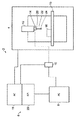
図1を参照すると、工作機械4、制御装置6、PC8、および送受信機インターフェース10を備える、工作機械装置2が図示される。工作機械4は、台15上に配置された工作物16に対してアナログプローブ14を保持するスピンドル12を移動させるためのモータ(図示せず)を備える。スピンドル12(およびしたがってアナログプローブ14)の位置は、エンコーダ等を使用して既知の方法で正確に測定される。かかる測定により、機械座標系(x、y、z)において規定されるスピンドル位置データが生成される。数値制御装置(NC)18(これは制御装置6の一部である)が、工作機械の作業領域内においてスピンドル12のx、y、z移動を制御し、スピンドル位置に関するデータを受信する。
Referring to FIG. 1, a
理解されるように、代替的実施形態においては、x次元、y次元、およびz次元の中の任意または全てにおける相対移動は、スピンドルに対する台15の移動により実現され得る。さらに、アナログプローブ14および工作物16の相対回転移動は、スピンドル12の一部(例えばスピンドル上に取り付けられた回転/関節ヘッド)および/または台15の一部(例えば回転台)により実現され得る。さらに、移動は、例えばxのみおよび/またはyのみなど、より低い次元に制約され得る。さらに、説明される実施形態は、デカルト座標系工作機械を備えるが、理解されるように、必ずしもそうである必要はなく、例えば非デカルト座標系工作機械であることが可能である。さらに、多数の他の異なるタイプの工作機械(旋盤を含む)、ならびにパラレルキネマティックマシンおよびロボットアームが、知られており、本発明と共に使用され得る。
As will be appreciated, in alternative embodiments, relative movement in any or all of the x, y, and z dimensions may be achieved by movement of the
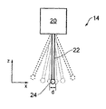
説明される実施形態においては、アナログプローブ14は、プローブ本体20と、プローブ本体20から延在する工作物接触スタイラス22とを備え、スタイラス22の遠位端部に工作物接触先端部24(この場合、これは球状スタイラスボールの形態である)の形態の表面検出領域を有する、コンタクトアナログプローブである。アナログプローブ14は、プローブ幾何学系(a、b、c)においてスタイラス22の偏向を測定する。(しかし、理解されるように、必ずしもそうである必要はなく、例えば、アナログプローブは、1次元もしくは2次元のみにおける偏向を測定することが可能であり、またはさらには偏移方向を示さずに偏向度を示す出力を生成することも可能である)。また、プローブ14は、送受信機インターフェース10との間で無線通信する(例えば、電波送信機、光送信機、または他の無線送信機を経由して)送受信機(図示せず)を備える。
In the described embodiment, the
上述のように、アナログ測定プローブは、測定範囲が制限される。例えば、コンタクトアナログプローブに関しては、それらは、x次元、y次元、およびz次元においてそれらを偏向し得る物理的最大量を有することが可能である。これだけではなく、プローブは、最大物理的範囲のある下位範囲内において最適に機能するように構成されることもまた可能である。例えば、図2(a)は、図1のアナログプローブを示し、実線は、休止(例えば非偏向)位置におけるスタイラス22の位置を表す。破線で示される最外スタイラス位置は、x次元におけるスタイラスの最大物理的偏向を表す。しかし、プローブは、スタイラスが最大物理的偏向未満の量だけ偏向された場合に、最も正確になるように構成され得ることが可能である。また、プローブは、スタイラスが最小下限しきい値だけ偏向された場合に、最も正確になるようにも構成され得ることもまた可能である。例えば、アナログプローブ14は、第1の例えば好ましい測定範囲を有することが可能であり、その上限境界および下限境界が、図2(a)において点線として示されるスタイラス位置によって図示される。したがって、示すように、好ましい測定範囲外である、スタイラスの休止位置に近い中間部に、デッドスペース「d」(x次元における)が存在する。
As described above, the measurement range of the analog measurement probe is limited. For example, for contact analog probes, they can have a physical maximum that can deflect them in the x, y, and z dimensions. Not only this, the probe can also be configured to function optimally within a certain subrange of the maximum physical range. For example, FIG. 2 (a) shows the analog probe of FIG. 1, and the solid line represents the position of the
理解されるように、これと同じことが、y次元における偏向においても当てはまる。さらに、説明される実施形態においては、z軸における最大物理的偏向範囲と、プローブが最も正確な結果を提供するように設定された範囲であるz軸偏向の下位範囲(好ましい測定範囲)とがさらに存在する。 As will be appreciated, the same is true for deflection in the y dimension. Further, in the described embodiment, there is a maximum physical deflection range in the z-axis and a sub-range of z-axis deflection (preferred measurement range), which is the range where the probe is set to provide the most accurate results. There is more.
図2(b)に示す点線28は、x次元およびz次元において得られるアナログプローブ14の好ましい測定範囲の領域を概略的に示す。理解されるように、かかる範囲は、実際には3次元方向に広がり、したがって実際には中央に小さな穴が切り抜かれた押しつぶされた半球の形状にほぼなる。
A dotted
また、図2(c)の点線は、インダクタンスプローブなどの非コンタクトプローブに関する好ましい測定範囲を概略的に示す。内方点線および外方点線は、最適測定性能のための最小プローブ/工作物離間境界および最大プローブ/工作物離間境界を表す。理解されるように、非コンタクトプローブに関して示されるこの好ましい測定範囲は、プローブの全測定範囲または単に全測定範囲の下位セットであることが可能である。理解されるように、全測定範囲は、非コンタクトプローブの表面検出領域と呼ばれ得るものとして見なすことが可能である。 Moreover, the dotted line of FIG.2 (c) shows the preferable measurement range regarding non-contact probes, such as an inductance probe, roughly. The inner and outer dotted lines represent the minimum probe / workpiece separation boundary and the maximum probe / workpiece separation boundary for optimal measurement performance. As will be appreciated, this preferred measurement range shown for non-contact probes can be the entire measurement range of the probe or just a subset of the entire measurement range. As will be appreciated, the entire measurement range can be viewed as what can be referred to as the surface detection area of a non-contact probe.
理解されるように、好ましい測定範囲のサイズは、プローブごとに異なる。コンタクトアナログプローブの場合には、それは、例えば任意の所与の次元において+/0.8mm以下であり、例えば任意の所与の次元において+/0.725mm以下であり、例えば任意の所与の次元において+/0.5mm以下であり、例えばいくつかの状況においては任意の所与の次元において+/0.3mm以下である(スタイラス休止位置から測定される)ことが可能である。また、当然ながら、スタイラスが、好ましい測定範囲に到達する前に偏向して越えなければならないデッドゾーンが、スタイラス位置の直ぐ周囲に存在してもよく、これは、例えば任意の所与の次元においてスタイラス休止位置から+/−0.2mm以上である、例えば任意の所与の次元においてスタイラス休止位置から+/−0.1mm以上である、例えば任意の所与の次元において+/−0.125mm以上である(やはりスタイラス休止位置から測定される)ことが可能である。 As will be appreciated, the preferred measurement range size varies from probe to probe. In the case of a contact analog probe, it is for example + / 0.8 mm or less in any given dimension, for example + / 0.725 mm or less in any given dimension, for example any given dimension. It can be + / 0.5 mm or less in the dimension, for example in some situations + / 0.3 mm or less (measured from the stylus rest position) in any given dimension. Also, of course, there may be a dead zone immediately around the stylus position that must be deflected before the stylus reaches the preferred measurement range, for example in any given dimension. +/− 0.2 mm or more from the stylus rest position, eg +/− 0.1 mm or more from the stylus rest position in any given dimension, eg +/− 0.125 mm in any given dimension This is again possible (again measured from the stylus rest position).
本発明は、プローブが、対象の表面上の基準測定ラインに沿って、その好ましい測定範囲内においてデータを常に収集するように維持されなければならないという従来の観点から逸脱する。むしろ、以下において説明される実施形態から明らかなように、本発明は、プローブの好ましい測定範囲の内外の両方において、基準測定ラインに沿った測定の実現を可能にする。しかし、いくつかの望ましくない状況が回避されることが好ましいこととなり得る。例えば、コンタクトアナログプローブの場合には、プローブの過剰偏向が、特にスタイラスまたはプローブの破損リスクをもたらし得る過剰偏向が、回避されることが好ましいこととなり得る。非コンタクトアナログプローブの場合には、プローブと対象との間の接触が完全に回避されることが好ましいこととなり得る。したがって、以下において開示される技術は、かかる望ましくない状況を回避しつつも、走査測定データを迅速に取得することを可能にする。 The present invention departs from the conventional point of view that the probe must be maintained along the reference measurement line on the surface of the object to always collect data within its preferred measurement range. Rather, as will be apparent from the embodiments described below, the present invention enables the realization of measurements along a reference measurement line both inside and outside the preferred measurement range of the probe. However, it may be preferable to avoid some undesirable situations. For example, in the case of contact analog probes, it may be preferable to avoid over-deflection of the probe, particularly over-deflection, which can lead to risk of stylus or probe failure. In the case of non-contact analog probes, it may be preferable to avoid contact between the probe and the object completely. Thus, the techniques disclosed below allow scanning measurement data to be acquired quickly while avoiding such undesirable situations.
図3は、本発明の一実施形態にしたがって組み込まれる一般的な手順100を示す。本方法は、測定すべき部分のモデルがPC8にロードされる時点であるステップ102にて開始する。理解されるように、このステップは、測定すべき工作物が未知である実施形態においては実施されなくてもよい。ステップ104において、工作物16の走査測定データを取得するためのアナログプローブ14の動作経路を規定するプログラムが、生成される。理解されるように、工作物16がアナログプローブ14と共にまたはその代わりに移動され得る(例えば可動台15により)実施形態においては、次いで、このプログラムは、工作物16の動作経路をさらに規定し得る。換言すれば、ステップ104は、アナログプローブ14が工作物16に関する走査測定データを収集し得るように、アナログプローブ14と工作物16との間の相対動作経路を計画することを含む。説明される実施形態においては、動作経路は、図4から図6との関連における以下の説明からより明らかになるように、アナログプローブおよび工作物が複数回にわたり互いに対して前後にトラバースするように設定される。ステップ106において、プログラムは、API26を経由してNC18にロードされる。ステップ108において、NC18は、プログラムの命令を解釈し、モータ制御信号を生成する。このモータ制御信号は、プログラムにより規定されるトラバースの中の1つにしたがってアナログプローブ14を移動させるように工作機械4のモータ(図示せず)に命じるために使用される。同時に、複数の手順を含む測定データが、記録される。特に、スピンドル位置データ(x、y、z)(上述のように工作機械4においてエンコーダにより生成される)が、NC18を経由してPC8に送られる。さらに、プローブ偏向データ(a、b、c)(上述のようにアナログプローブにより取得される)が、プローブ送受信機インターフェース10を経由してPC8にやはり送られる。PC8は、スピンドル位置データ(x、y、z)およびプローブ偏向データ(a、b、c)を組み合わせることにより、機械座標ジオメトリ内で表面の位置を規定する測定値セットを生成する。
FIG. 3 illustrates a
次いで、ステップ110において、PC8は、その走査により、完了したばかりのトラバースにおいて取得されたアナログプローブ14からのデータが、その好ましい測定範囲内に完全に含まれるか否かを判定する。アナログプローブ14からのデータが、その好ましい測定範囲内に完全に含まれる場合には、次いで、本プロセスは、全ての関連測定データが取得されたことにより終了する。アナログプローブ14からのデータが、その好ましい測定範囲内に完全には含まれない場合には、次いで、制御は、ステップ112に進み、PC8は、後々の動作経路の知識と、さらには実行されたばかりのトラバース(および/または他の以前のトラバース)において収集された測定データとに基づき、アナログプローブ14がその好ましい最大偏向を超過する可能性があるか否かを判定する。アナログプローブ14が、その好ましい最大偏向を超過する可能性がある場合には、次いで、ステップ114において、それは、NC18のプログラムおよび/またはNC18にロードされたプログラムにより参照される変数を操作することにより、これがかかる後々のトラバースにおいて生じないように確保する。理解されるように、それは、修正される次のトラバースか、またはいくつかの他の後々のトラバースもしくはさらには複数の後々のトラバースであることが可能である。
Then, in
理解されるように、既存の動作経路の更新は、完全に新規の動作経路を毎回生成するよりも迅速であり得る。特に、ステップ112および114は、NC18が、プローブ偏向データを受信し、ステップ112および114をそれ自体で実施する場合には、非常に迅速に実施され得る。
As will be appreciated, updating an existing motion path may be quicker than creating a completely new motion path each time. In particular, steps 112 and 114 can be performed very quickly if NC 18 receives probe deflection data and performs
本発明の実施形態は、図4から図6を参照としてさらに説明される。図4に示す第1の実施形態においては、既知の部分を測定する方法が示される。この部分は、その基準形状、基準寸法、および基準位置が既知である点において、既知である。説明される実施形態においては、基準形状は、実線30により図示され、その実形状からの逸脱が、点線32により図示される。示すように、実形状32は、製造の不正確さにより基準形状または予期される形状から逸脱する。特に、図示するように、実形状は、その形状中に予期しないくぼみ34およびこぶ35を備える。予め定められた動作経路は、対象16の表面17上に同一の基準測定ライン19に沿って2つのトラバースを備える(図5(e)においてより容易に理解される)が、対象の表面とスタイラスボール24の基準中心点との間の基準オフセット距離は、かかる逸脱がアナログプローブの好ましい測定範囲内においても測定され得るように確保するために、これらの2つのトラバースで異なる。動作経路に沿ったスタイラスボール24の中心点の基準位置は、点線40により示される。
Embodiments of the present invention are further described with reference to FIGS. In the first embodiment shown in FIG. 4, a method for measuring a known part is shown. This part is known in that its reference shape, reference dimension, and reference position are known. In the described embodiment, the reference shape is illustrated by the
説明される実施形態においては、第1のトラバースは、工作物16の表面17から最も遠方に離れたトラバースである。工作物16の表面17中の予期しないくぼみにより、図3にしたがって、ステップ110において、トラバースの長さに沿った全ての測定値が、アナログプローブの好ましい測定範囲内において取得されたわけではないと判定される。したがって、予め定められた動作経路の第2のトラバースが、実施されることになる。しかし、上述のように、予期しないくぼみ34に加えて、予期しないこぶ35が、工作物16の表面17中にさらに存在する。このこぶ35は、第1のトラバースの間に検出/測定されているため、ステップ112および114にしたがって、予め定められた動作経路に対する修正がない場合に、こぶによりプローブが第2のトラバース上において過剰偏向するか否かが判定される。この場合に過剰偏向すると判定された場合には、予め定められた動作経路を修正することが決定される。動作経路のかかる修正の効果として、基準プローブ先端部中心点は、図4において破線42により図示されるように、その元の基準経路から逸脱する。説明される実施形態においては、これは、元の予め定められた動作経路からシフトするスピンドル12によりおよびしたがってプローブヘッド20により達成される。理解されるように、これは、他の方法で達成され得る。例えば、プローブ14が、関節ヘッド上に取り付けられる場合には、基準先端部中心点の経路のシフトもまた、プローブ14を関節ヘッドの回転軸を中心として回転させることによって達成され得る。任意には、台15が、可動である場合には、これは、台を移動させることによって達成され得る。
In the described embodiment, the first traverse is the traverse farthest away from the
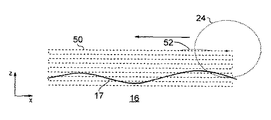
また、本発明の方法は、例えば未知の形状、寸法、および/または位置の部分などの、未知の部分を測定する場合にも価値を有する。例えば、図5(a)から図5(e)を参照すると、未知の部分は、(図3を参照として)ステップ102において基準対象データをロードし(実際には未知の部分に関する基準対象データは存在しない)、ステップ104においてかかる基準対象データに基づく経路を生成する代わりに、複数回にわたり対象上において同一の基準測定ライン19にわたりコンタクトアナログプローブ14のスタイラス先端部24を前後に移動させ、しかしスタイラス先端部の中心点と対象の表面との間の基準離間を毎回縮小させることを含む、動作経路を単に生成することによって測定され得る。例えば、図5(a)に示すように、破線50で図示されるようにそれと表面との間の基準オフセットが各トラバースごとに低減される状態で、その中心点が、複数回にわたり対象の表面上において共通の基準測定ライン19に沿って直線方向に前後に名目上移動するように、スタイラス先端部24を移動させるように初めに設定された、予め定められた動作経路が生成される。図示するように、対象16の形状、寸法、および/または位置が、未知であるため、基準先端部中心の経路の形状は、部分の形状と必ずしも同一ではなく、また測定作業がそれが必要とする全ての測定データを確実に取得するために、予め定められた動作経路が、実際に必要とされるよりもはるかに多数のトラバースを含むことが可能である。
The method of the present invention is also valuable when measuring unknown parts, such as parts of unknown shape, size and / or position. For example, referring to FIG. 5 (a) to FIG. 5 (e), the unknown part loads the reference object data in step 102 (see FIG. 3) (actually the reference object data for the unknown part is Instead of generating a path based on such reference object data in
図示する例においては、予め定められた動作経路の更新は、連続トラバースにおいてスタイラス22の過剰偏向が回避されるように、各トラバースの終了時に判定および適用される(トラバースに沿ったプローブの中心点の基準位置に対する効果は、点線52により図示される)。図5(a)から図5(e)に示す例においては、ステップ110から114のループは、図5(d)に示すように、トラバースの長さについて測定プローブの好ましい測定範囲内に測定データが位置する場合に、本方法が終了し、対象のその後の予め定められたトラバースが実施されなくなるまで、継続する。
In the illustrated example, a predetermined motion path update is determined and applied at the end of each traverse (probe center point along the traverse) so that excessive deflection of the
説明される実施形態においては、各トラバース後に、予め定められた動作経路が、例えば対象の表面中のこぶまたはくぼみなどの基準形状からの予期しない逸脱などの、以前の走査から判定された表面形状17を考慮に入れるために更新を必要とするか否かが判定される。やはり理解されるように、各トラバース後に更新される予め定められた動作経路を有するのではなく、本方法は、トラバースごとに動作経路を生成することを代わりに含むことが可能である。例えば、図7を参照すると、方法200は、ステップ202において、ユーザがPC8に基準対象データをロードすることと、次いでステップ204において少なくとも1回にわたり対象に対してトラバースするアナログプローブの動作経路を規定するプログラムを生成することとを含むことが可能である。次いで、ステップ206において、このプログラムはNC18にロードされ、ステップ208において、少なくとも1つのトラバースが実施される。ステップ210において、工作物の表面に関してより多量のデータが必要とされると判定された場合には、次いで、制御は、ステップ212へと進み、異なる基準測定ラインに沿って工作物の表面にわたり少なくとも1つのさらなるトラバースを実施するためのアナログプローブの動作経路を規定する、新規のプログラムが生成される。この新規のプログラムにより規定されるアナログプローブの動作経路は、少なくとも1つの以前のトラバースから得られる表面データを使用して生成され得る。この新規のプログラムは、次いでステップ214においてNC18にロードされ、次いでステップ208において実施される。このループは、対象の表面に関する十分なデータが取得されるまで、継続される。
In the described embodiment, after each traversal, the predetermined motion path is a surface shape determined from a previous scan, such as an unexpected deviation from a reference shape such as a hump or indentation in the surface of the object. It is determined whether an update is required to take 17 into account. As will also be appreciated, rather than having a predetermined motion path that is updated after each traverse, the method may instead include generating a motion path for each traverse. For example, referring to FIG. 7, the
図6は、対象の各トラバースが、対象の表面上の同一の基準測定ラインに沿って実施されるのではなく、対象の表面上の基準測定ラインが、個々のトラバースごとに異なる、本発明の代替的実施形態を示す。対象の表面に沿ったプローブ先端部中心点の基準経路は、点線60により図示され、これにより、この経路が、工作物16の表面17にわたり一連のトラバースを備えることが分かる。示すように、説明される実施形態においては、各トラバースの基準測定ラインの形状は、実質的に同一であり、互いに対して平行に延在する。しかし、理解されるように、これは、必ずしもそうである必要はない。上述の実施形態と同様に、複数のトラバースの経路が、NCにロードされ得ると共に、次いで後のトラバースが、以前のトラバースに基づき更新され得る。任意には、本方法は、NCに第1のトラバースのみに対する命令をロードすることを含むことが可能であり、次いで、次のトラバースに対する命令は、第1のトラバースが完了すると生成され得るため、これにより、第1のトラバースからのデータが、次のトラバースの生成時に考慮に入れられ得る。
FIG. 6 shows that each traverse of an object is not performed along the same reference measurement line on the surface of the object, but the reference measurement line on the surface of the object is different for each individual traverse. An alternative embodiment is shown. The reference path of the probe tip center point along the surface of interest is illustrated by the dotted
第1のトラバースに対する命令は、多数の異なる方法で生成され得る。例えば、部分が、既知の部分である場合には、測定すべき対象が予期されたようなものとなり、経路がそれに応じて生成され得るものと仮定することが可能である。任意には、これは、トラバースに沿った走査が実施される前に、基準測定ラインに沿って対象の測定の選択を行うことによって確認され得る。任意には、特にこの部分が、未知である場合には、本方法は、第1のトラバースに沿って少なくともいくつかの測定情報を取得するために調査測定作業を実施することを含み得る。例えば、調査測定作業は、図4または図5において説明されるものと同様の作業を実施することを含み得る。さらに任意には、タッチトリガタイプ測定が、第1のトラバースの実施前に第1のトラバースの長さに沿って複数の離散点にて実施され得る。別のオプションとしては、本出願の背景の章において上述したようなドリップフィード技術が、第1のトラバースを実施するために利用され得る。 The instructions for the first traverse can be generated in a number of different ways. For example, if the part is a known part, it can be assumed that the object to be measured is as expected and the path can be generated accordingly. Optionally, this can be confirmed by making a selection of the measurement of interest along the reference measurement line before the scan along the traverse is performed. Optionally, particularly if this portion is unknown, the method may include performing a survey measurement operation to obtain at least some measurement information along the first traverse. For example, the survey measurement task may include performing a task similar to that described in FIG. 4 or FIG. Further optionally, touch trigger type measurements may be performed at a plurality of discrete points along the length of the first traverse prior to performing the first traverse. As another option, drip feed technology as described above in the background section of this application may be utilized to perform the first traverse.
したがって、第1のトラバースは、未知のトラバースとして処理され得ると共に、後のトラバースは、既知のトラバースとして処理され得る(それらが少なくとも1つの以前のトラバースから取得された測定情報に基づき生成されることにより)。しかし、本方法は、プローブの出力が、後のトラバースの間にモニタリングされることにより、例えばプローブがその好ましい測定範囲外に進むなど、予期しない測定が行われた場合に、それが、未知のトラバースの実施へと戻るように、構成され得る(例えば、図4および図5に示すものなどのドリップフィード技術またはマルチプルパス/ラスタ走査技術などを利用して)。 Thus, the first traverse can be processed as an unknown traverse and the subsequent traverses can be processed as known traversals (that they are generated based on measurement information obtained from at least one previous traverse. By). However, this method can be used to monitor the output of a probe during a subsequent traversal, for example, if an unexpected measurement is made, such as when the probe goes out of its preferred measurement range, It can be configured to return to performing a traverse (eg, utilizing drip feed techniques such as those shown in FIGS. 4 and 5 or multiple pass / raster scanning techniques, etc.).
図示する実施形態においては、走査経路は、対象の表面にわたり前後に複数のトラバースを含む。当然ながら、これらのトラバースは、いずれも同一方向に実施され得る。さらに、走査経路は、複数のトラバースを含まなくてもよい。例えば、予め定められた間隔で更新される1つのみのトラバースが、実施され得る。さらに、いずれのトラバースの形状も、ほぼ直線状のラインを必ずしも含む必要はない。例えばトラバースの経路は、例えば左右方向動作においてなど、側方に曲折することが可能である。さらに、走査経路は、必ずしも前後方向に基準プローブ先端部中心を移動させることを含む必要はない。例えば、各トラバースが、対象の表面にわたり屈曲(例えば蛇行)方向に基準プローブ先端部中心を移動させることを含むことが可能である。したがって、上述の実施形態は、基準測定ラインが、対象の表面上の直線状ラインのみに対応する平面内に制約されるように説明されるが、これは、必ずしもそうである必要はなく、各トラバースが、対象の表面の広い範囲にわたり対応することが可能である。 In the illustrated embodiment, the scan path includes a plurality of traverses back and forth across the surface of the object. Of course, both of these traverses can be performed in the same direction. Furthermore, the scanning path may not include a plurality of traverses. For example, only one traverse that is updated at predetermined intervals may be performed. Furthermore, the shape of any traverse need not necessarily include a substantially straight line. For example, the traverse path can be bent sideways, such as in a left-right motion. Further, the scanning path does not necessarily include moving the center of the reference probe tip in the front-rear direction. For example, each traverse can include moving the reference probe tip center in a bending (eg, serpentine) direction across the surface of the object. Thus, although the above embodiments are described such that the reference measurement line is constrained in a plane that corresponds only to a straight line on the surface of interest, this need not necessarily be the case. Traverse can cover a wide range of the surface of interest.
上述の実施形態においては、トラバースは、高速で(例えば、工作物感知部分(例えばスタイラス先端部24)および対象が、少なくとも16mm/sにて、好ましくは少なくとも25mm/sにて、より好ましくは少なくとも50mm/sにて、特に好ましくは少なくとも100mm/sにて、例えば少なくとも250mm/sにて、互いに対して移動する状態で)実施され得る。なぜならば、プローブ14が、その好ましい測定範囲未満のデータを取得するか否かは重要ではなく、また、より以前のトラバースに基づく後のトラバースの更新が、プローブ14および対象16が不利な位置関係にならない(例えば、プローブのスタイラスが過剰偏向されるなど)という確実性をプロセスにもたらすからである。
In the above-described embodiments, the traverse is fast (eg, workpiece sensing portion (eg, stylus tip 24) and the object is at least 16 mm / s, preferably at least 25 mm / s, more preferably at least At 50 mm / s, particularly preferably at least 100 mm / s, for example at least 250 mm / s, with movement relative to one another). This is because it does not matter whether the
Claims (15)
前記フィーチャに関する走査測定データを収集するために前記アナログ測定プローブおよび前記対象が互いに対して移動し得る予め定められた動作経路を工作機械の制御装置にロードするステップであって、前記予め定められた動作経路は、前記アナログ測定プローブが各トラバースに沿った走査測定データを取得するための複数のトラバースを含む、ステップと、
前記予め定められた動作経路にしたがって前記アナログ測定プローブおよび/または前記対象を相対的に移動させることにより走査オペレーションを実施するステップとを含み、
前記予め定められた動作経路は、以前に収集された走査測定データに基づき前記トラバースの終了時において更新されることを特徴とする方法。 A method of measuring a feature of interest using an analog measurement probe mounted on a machine tool device, comprising:
Loading the machine tool controller with a predetermined motion path through which the analog measurement probe and the object can move relative to each other to collect scanning measurement data relating to the feature , An operating path includes a plurality of traverses for the analog measurement probe to acquire scan measurement data along each traverse; and
Performing a scanning operation by relatively moving the analog measurement probe and / or the object according to the predetermined operating path;
The predetermined operating path is updated at the end of the traverse based on previously collected scan measurement data.
Applications Claiming Priority (5)
| Application Number | Priority Date | Filing Date | Title |
|---|---|---|---|
| EP12250093 | 2012-04-18 | ||
| EP12250093.7 | 2012-04-18 | ||
| US201261720323P | 2012-10-30 | 2012-10-30 | |
| US61/720,323 | 2012-10-30 | ||
| PCT/GB2013/050964 WO2013156765A1 (en) | 2012-04-18 | 2013-04-16 | A method of analogue measurement scanning on a machine tool and corresponding machine tool apparatus |
Publications (3)
| Publication Number | Publication Date |
|---|---|
| JP2015531852A JP2015531852A (en) | 2015-11-05 |
| JP2015531852A5 JP2015531852A5 (en) | 2016-06-23 |
| JP6346167B2 true JP6346167B2 (en) | 2018-06-20 |
Family
ID=49382986
Family Applications (1)
| Application Number | Title | Priority Date | Filing Date |
|---|---|---|---|
| JP2015506298A Active JP6346167B2 (en) | 2012-04-18 | 2013-04-16 | Analog measurement scanning method in machine tools and corresponding machine tool apparatus |
Country Status (6)
| Country | Link |
|---|---|
| US (1) | US9726481B2 (en) |
| EP (1) | EP2839240B1 (en) |
| JP (1) | JP6346167B2 (en) |
| CN (1) | CN104969028B (en) |
| TW (1) | TWI503523B (en) |
| WO (1) | WO2013156765A1 (en) |
Families Citing this family (16)
| Publication number | Priority date | Publication date | Assignee | Title |
|---|---|---|---|---|
| WO2013050729A1 (en) * | 2011-10-06 | 2013-04-11 | Renishaw Plc | Measurement method |
| US9733060B2 (en) * | 2012-04-18 | 2017-08-15 | Renishaw Plc | Method of finding a feature using a machine tool |
| WO2013156769A1 (en) * | 2012-04-18 | 2013-10-24 | Renishaw Plc | A method of measurement on a machine tool and corresponding machine tool apparatus |
| JP6007873B2 (en) * | 2013-08-30 | 2016-10-12 | トヨタ自動車株式会社 | Robot and control method thereof |
| JP6159647B2 (en) * | 2013-11-12 | 2017-07-05 | 三菱重工工作機械株式会社 | On-machine measuring method using machining inspection work of machine tool |
| US10215560B2 (en) * | 2015-03-24 | 2019-02-26 | Kla Tencor Corporation | Method for shape classification of an object |
| GB201505999D0 (en) | 2015-04-09 | 2015-05-27 | Renishaw Plc | Measurement method and apparatus |
| US10545019B2 (en) * | 2015-04-14 | 2020-01-28 | Hexagon Metrology, Inc. | CMM probe path controller and method |
| US9952580B2 (en) * | 2016-01-29 | 2018-04-24 | The Boeing Company | Method and an apparatus for machining a part for an assembly |
| GB201806830D0 (en) * | 2018-04-26 | 2018-06-13 | Renishaw Plc | Surface finish stylus |
| GB201806828D0 (en) * | 2018-04-26 | 2018-06-13 | Renishaw Plc | Surface finish stylus |
| EP3611465A1 (en) * | 2018-08-14 | 2020-02-19 | Renishaw PLC | Method, computer program and apparatus for measurement cycle generation in a touch trigger coordinate machine |
| EP3623883A1 (en) | 2018-09-17 | 2020-03-18 | HAAS Schleifmaschinen GmbH | Method and machine tool for machining workpieces with unknown workpiece geometry |
| US10814492B2 (en) | 2019-02-15 | 2020-10-27 | R-Go Robotics Ltd | Apparatus and method for surface traversing with capacitive sensing of surface |
| JP2022075107A (en) * | 2020-11-06 | 2022-05-18 | 株式会社ミツトヨ | Form measuring device and abnormality detection method |
| CN112925263A (en) * | 2021-01-25 | 2021-06-08 | 深圳市玄羽科技有限公司 | CNC (computer numerical control) machine probe and control method thereof |
Family Cites Families (62)
| Publication number | Priority date | Publication date | Assignee | Title |
|---|---|---|---|---|
| US4153998A (en) | 1972-09-21 | 1979-05-15 | Rolls-Royce (1971) Limited | Probes |
| US4166323A (en) | 1973-09-14 | 1979-09-04 | Maag Gear-Wheel & Machine Co. Ltd. | Gear tester for profile and lead testing |
| GB1551218A (en) | 1975-05-13 | 1979-08-22 | Rolls Royce | Probe for use in displacement measuring apparatus |
| GB2174216B (en) | 1985-03-19 | 1988-10-26 | Mitutoyo Mfg Co Ltd | Method of operating a coordinate measuring instrument |
| CN85105480A (en) | 1985-07-17 | 1987-01-14 | 通用电气公司 | Machine tool monitor gaging technigue |
| GB8713715D0 (en) | 1987-06-11 | 1987-07-15 | Renishaw Plc | Workpiece inspection method |
| JPH02145908A (en) | 1988-11-28 | 1990-06-05 | Okuma Mach Works Ltd | Automatic setting for correcting deflection of stylus in digitizing device |
| US5189806A (en) * | 1988-12-19 | 1993-03-02 | Renishaw Plc | Method of and apparatus for scanning the surface of a workpiece |
| GB8908854D0 (en) | 1989-04-19 | 1989-06-07 | Renishaw Plc | Method of and apparatus for scanning the surface of a workpiece |
| GB9110818D0 (en) | 1991-05-21 | 1991-07-10 | Renishaw Metrology Ltd | A method of measuring workpieces using a surface contacting measuring probe |
| DE4245012B4 (en) | 1992-04-14 | 2004-09-23 | Carl Zeiss | Method for measuring shaped elements on a coordinate measuring machine |
| DE69309588T2 (en) | 1992-09-12 | 1997-07-24 | Renishaw Plc | Method and device for scanning the surface of a workpiece |
| US5948972A (en) | 1994-12-22 | 1999-09-07 | Kla-Tencor Corporation | Dual stage instrument for scanning a specimen |
| GB2302589B (en) * | 1995-06-21 | 1998-11-11 | Zeiss Stiftung | Probe head for coordinate measuring machines with a clamping device for clamping the deflectable part of the probe head |
| DE19730471C5 (en) | 1997-07-16 | 2009-02-19 | Hexagon Metrology Gmbh | Method for scanning with a coordinate measuring machine |
| US6580964B2 (en) | 1998-10-24 | 2003-06-17 | Renishaw Plc | Calibrations of an analogue probe and error mapping |
| JP4660779B2 (en) | 2000-08-18 | 2011-03-30 | 学校法人 中央大学 | Method for evaluating position error of moving device and method for improving moving accuracy based on the evaluation result |
| JP3905771B2 (en) | 2001-03-02 | 2007-04-18 | 株式会社ミツトヨ | Calibration method and apparatus for measuring machine |
| GB0118492D0 (en) | 2001-07-30 | 2001-09-19 | Renishaw Plc | A machine tool control process and apparatus therfor |
| GB0126232D0 (en) * | 2001-11-01 | 2002-01-02 | Renishaw Plc | Calibration of an analogue probe |
| GB0210990D0 (en) | 2002-05-14 | 2002-06-19 | Rolls Royce Plc | Method of generating an inspection program and method of generating a visual display |
| GB0215152D0 (en) | 2002-07-01 | 2002-08-07 | Renishaw Plc | Probe or stylus orientation |
| GB0215478D0 (en) | 2002-07-04 | 2002-08-14 | Renishaw Plc | Method of scanning a calibrating system |
| GB0220158D0 (en) | 2002-08-30 | 2002-10-09 | Renishaw Plc | Method of scanning |
| CN1297796C (en) | 2003-07-02 | 2007-01-31 | 西安交通大学 | Chromatographic scanning three-dimension measuring method and device linear array photoelectric sensor |
| GB0322115D0 (en) | 2003-09-22 | 2003-10-22 | Renishaw Plc | Method of error compensation |
| GB0322362D0 (en) | 2003-09-24 | 2003-10-22 | Renishaw Plc | Measuring methods for use on machine tools |
| US7543393B2 (en) * | 2003-12-16 | 2009-06-09 | Renishaw Plc | Method of calibrating a scanning system |
| GB0329098D0 (en) | 2003-12-16 | 2004-01-21 | Renishaw Plc | Method of calibrating a scanning system |
| GB0400144D0 (en) | 2004-01-06 | 2004-02-11 | Renishaw Plc | Inspection system |
| CN1727871A (en) | 2004-01-14 | 2006-02-01 | Fei公司 | Method of operating a probe microscope |
| EP1555676A3 (en) | 2004-01-14 | 2006-09-13 | FEI Company | Method of operating a probe microscope |
| JP2007529734A (en) | 2004-03-18 | 2007-10-25 | レニショウ パブリック リミテッド カンパニー | Object scanning |
| JP4782990B2 (en) | 2004-05-31 | 2011-09-28 | 株式会社ミツトヨ | Surface scanning measuring device, surface scanning measuring method, surface scanning measuring program, and recording medium |
| JP4510520B2 (en) | 2004-06-01 | 2010-07-28 | キヤノン株式会社 | Shape measuring method and shape measuring apparatus |
| GB0414649D0 (en) | 2004-06-30 | 2004-08-04 | Renishaw Plc | Generation of a CNC machine tool control program |
| GB0417536D0 (en) | 2004-08-06 | 2004-09-08 | Renishaw Plc | The use of surface measurement probes |
| GB0508273D0 (en) | 2005-04-25 | 2005-06-01 | Renishaw Plc | Method for scanning the surface of a workpiece |
| GB0508395D0 (en) | 2005-04-26 | 2005-06-01 | Renishaw Plc | Method for scanning the surface of a workpiece |
| US20070050089A1 (en) | 2005-09-01 | 2007-03-01 | Yunquan Sun | Method for detecting the position and orientation of holes using robotic vision system |
| GB0608235D0 (en) | 2006-04-26 | 2006-06-07 | Renishaw Plc | Differential calibration |
| GB0611109D0 (en) | 2006-06-06 | 2006-07-19 | Renishaw Plc | A method for measuring workpieces |
| GB0625260D0 (en) * | 2006-12-19 | 2007-01-24 | Renishaw Plc | A method for measuring a workpiece using a machine tool |
| GB0703423D0 (en) * | 2007-02-22 | 2007-04-04 | Renishaw Plc | Calibration method and apparatus |
| EP1978328B1 (en) | 2007-04-03 | 2015-02-18 | Hexagon Metrology AB | Oscillating scanning probe with constant contact force |
| GB0707921D0 (en) | 2007-04-24 | 2007-05-30 | Renishaw Plc | Apparatus and method for surface measurement |
| US8919005B2 (en) | 2007-04-30 | 2014-12-30 | Renishaw Plc | Analogue probe and method of operation |
| EP1988357B1 (en) | 2007-05-04 | 2018-10-17 | Hexagon Technology Center GmbH | Coordinate measuring method and device |
| GB0713639D0 (en) | 2007-07-13 | 2007-08-22 | Renishaw Plc | Error correction |
| GB0716218D0 (en) * | 2007-08-20 | 2007-09-26 | Renishaw Plc | Measurement path generation |
| JP5091702B2 (en) | 2008-02-04 | 2012-12-05 | 株式会社ミツトヨ | Probe straightness measurement method |
| US7752000B2 (en) | 2008-05-02 | 2010-07-06 | Qcept Technologies, Inc. | Calibration of non-vibrating contact potential difference measurements to detect surface variations that are perpendicular to the direction of sensor motion |
| JP4611403B2 (en) | 2008-06-03 | 2011-01-12 | パナソニック株式会社 | Shape measuring apparatus and shape measuring method |
| JP5684712B2 (en) | 2008-10-29 | 2015-03-18 | レニショウ パブリック リミテッド カンパニーRenishaw Public Limited Company | Method for coordinate measuring system |
| GB0900878D0 (en) | 2009-01-20 | 2009-03-04 | Renishaw Plc | Method for optimising a measurement cycle |
| EP2290486A1 (en) | 2009-08-28 | 2011-03-02 | Renishaw plc | Machine tool calibration method |
| JP5281992B2 (en) | 2009-08-28 | 2013-09-04 | 株式会社日立製作所 | Scanning probe microscope and measuring method using the same |
| JP5439157B2 (en) | 2009-12-22 | 2014-03-12 | 三菱重工業株式会社 | Gear measurement method |
| JP5690941B2 (en) | 2010-09-13 | 2015-03-25 | ヘキサゴン・テクノロジー・センター・ゲーエムベーハーHexagon Technology Center Gmbh | Method and apparatus for controlling surface scanning coordinate measuring apparatus |
| CN103328919B (en) | 2011-01-19 | 2016-08-17 | 瑞尼斯豪公司 | Analogue measurement for machine tool is popped one's head in and operational approach |
| WO2013050729A1 (en) * | 2011-10-06 | 2013-04-11 | Renishaw Plc | Measurement method |
| US9733060B2 (en) * | 2012-04-18 | 2017-08-15 | Renishaw Plc | Method of finding a feature using a machine tool |
-
2013
- 2013-04-16 CN CN201380031456.8A patent/CN104969028B/en active Active
- 2013-04-16 US US14/391,837 patent/US9726481B2/en active Active
- 2013-04-16 WO PCT/GB2013/050964 patent/WO2013156765A1/en active Application Filing
- 2013-04-16 EP EP13719595.4A patent/EP2839240B1/en active Active
- 2013-04-16 JP JP2015506298A patent/JP6346167B2/en active Active
- 2013-04-18 TW TW102113862A patent/TWI503523B/en active
Also Published As
| Publication number | Publication date |
|---|---|
| EP2839240B1 (en) | 2017-09-06 |
| CN104969028B (en) | 2018-06-01 |
| TWI503523B (en) | 2015-10-11 |
| US9726481B2 (en) | 2017-08-08 |
| EP2839240A1 (en) | 2015-02-25 |
| TW201350791A (en) | 2013-12-16 |
| US20150121710A1 (en) | 2015-05-07 |
| WO2013156765A1 (en) | 2013-10-24 |
| CN104969028A (en) | 2015-10-07 |
| JP2015531852A (en) | 2015-11-05 |
Similar Documents
| Publication | Publication Date | Title |
|---|---|---|
| JP6346167B2 (en) | Analog measurement scanning method in machine tools and corresponding machine tool apparatus | |
| JP6665227B2 (en) | Measurement methods in machine tools and corresponding machine tool devices | |
| JP6242856B2 (en) | How to find features using machine tools | |
| JP6199870B2 (en) | Measuring method | |
| WO2014076454A1 (en) | Method and apparatus for measuring a workpiece with a machine tool | |
| JP7113814B2 (en) | Method and apparatus for measuring objects | |
| JP6735735B2 (en) | A coordinate measuring method and apparatus for inspecting a workpiece, the method comprising generating a measurement correction value using a reference shape known not to substantially deviate from an ideal form, Coordinate measuring method and apparatus for inspecting a workpiece |
Legal Events
| Date | Code | Title | Description |
|---|---|---|---|
| A621 | Written request for application examination |
Free format text: JAPANESE INTERMEDIATE CODE: A621 Effective date: 20160418 |
|
| A521 | Request for written amendment filed |
Free format text: JAPANESE INTERMEDIATE CODE: A523 Effective date: 20160426 |
|
| A131 | Notification of reasons for refusal |
Free format text: JAPANESE INTERMEDIATE CODE: A131 Effective date: 20170214 |
|
| A977 | Report on retrieval |
Free format text: JAPANESE INTERMEDIATE CODE: A971007 Effective date: 20170215 |
|
| A601 | Written request for extension of time |
Free format text: JAPANESE INTERMEDIATE CODE: A601 Effective date: 20170515 |
|
| A02 | Decision of refusal |
Free format text: JAPANESE INTERMEDIATE CODE: A02 Effective date: 20171114 |
|
| A521 | Request for written amendment filed |
Free format text: JAPANESE INTERMEDIATE CODE: A523 Effective date: 20180313 |
|
| A911 | Transfer to examiner for re-examination before appeal (zenchi) |
Free format text: JAPANESE INTERMEDIATE CODE: A911 Effective date: 20180320 |
|
| TRDD | Decision of grant or rejection written | ||
| A01 | Written decision to grant a patent or to grant a registration (utility model) |
Free format text: JAPANESE INTERMEDIATE CODE: A01 Effective date: 20180424 |
|
| A61 | First payment of annual fees (during grant procedure) |
Free format text: JAPANESE INTERMEDIATE CODE: A61 Effective date: 20180524 |
|
| R150 | Certificate of patent or registration of utility model |
Ref document number: 6346167 Country of ref document: JP Free format text: JAPANESE INTERMEDIATE CODE: R150 |
|
| R250 | Receipt of annual fees |
Free format text: JAPANESE INTERMEDIATE CODE: R250 |
|
| R250 | Receipt of annual fees |
Free format text: JAPANESE INTERMEDIATE CODE: R250 |
|
| R250 | Receipt of annual fees |
Free format text: JAPANESE INTERMEDIATE CODE: R250 |