JP6199870B2 - Measuring method - Google Patents
Measuring method Download PDFInfo
- Publication number
- JP6199870B2 JP6199870B2 JP2014533974A JP2014533974A JP6199870B2 JP 6199870 B2 JP6199870 B2 JP 6199870B2 JP 2014533974 A JP2014533974 A JP 2014533974A JP 2014533974 A JP2014533974 A JP 2014533974A JP 6199870 B2 JP6199870 B2 JP 6199870B2
- Authority
- JP
- Japan
- Prior art keywords
- measurement
- stylus
- measurements
- series
- edge
- Prior art date
- Legal status (The legal status is an assumption and is not a legal conclusion. Google has not performed a legal analysis and makes no representation as to the accuracy of the status listed.)
- Active
Links
Images


Classifications
-
- G—PHYSICS
- G01—MEASURING; TESTING
- G01B—MEASURING LENGTH, THICKNESS OR SIMILAR LINEAR DIMENSIONS; MEASURING ANGLES; MEASURING AREAS; MEASURING IRREGULARITIES OF SURFACES OR CONTOURS
- G01B5/00—Measuring arrangements characterised by the use of mechanical techniques
- G01B5/004—Measuring arrangements characterised by the use of mechanical techniques for measuring coordinates of points
- G01B5/008—Measuring arrangements characterised by the use of mechanical techniques for measuring coordinates of points using coordinate measuring machines
-
- G—PHYSICS
- G01—MEASURING; TESTING
- G01B—MEASURING LENGTH, THICKNESS OR SIMILAR LINEAR DIMENSIONS; MEASURING ANGLES; MEASURING AREAS; MEASURING IRREGULARITIES OF SURFACES OR CONTOURS
- G01B5/00—Measuring arrangements characterised by the use of mechanical techniques
- G01B5/20—Measuring arrangements characterised by the use of mechanical techniques for measuring contours or curvatures
- G01B5/205—Measuring arrangements characterised by the use of mechanical techniques for measuring contours or curvatures of turbine blades or propellers
Description
本発明は、物体の特徴を測定する方法に関し、詳細には、物体の細長い縁部を測定する方法に関する。 The present invention relates to a method for measuring object features, and in particular to a method for measuring an elongated edge of an object.
物体の特徴の測定中、最初に特徴の位置を識別してから物体の正確な測定を実行することが有利である場合がある。たとえば、これは、ジェットエンジン内で使用されるタービンブリスク(blisk)上の羽根の縁部など、物体の縁部を測定する場合に当てはまる場合がある。そのような羽根は、たとえば、たとえば図1に示すようにCMM上に取り付けられたアナログプローブを使用して測定することができる。アナログプローブは、そのスタイラス先端部を羽根の縁部に接触させ、それに沿って走査させて測定データを取得するように、(予期されるブリスク形状のデータモデルを有する)CMMの制御を受けて駆動することができる。しかし、そのような羽根の縁部は、厚さ数ミリメートルと小さい可能性があり、それがわずか1または2ミリメートルだけ定位置から外れている場合でも、スタイラス先端部は羽根縁部に衝突しかつ/または羽根縁部から落下し、誤った測定を引き起こす可能性がある。具体的には、羽根縁部の走査中、スタイラス先端部は、表面の法線方向に、または少なくとも可能な限り表面の法線方向に、羽根表面内へ駆動されることが重要である。そうでない場合、スタイラス先端部は、表面に沿って滑る可能性があり、それによって羽根の測定に支障が出る可能性がある。 During the measurement of object features, it may be advantageous to first identify the location of the feature and then perform an accurate measurement of the object. For example, this may be the case when measuring the edge of an object, such as the edge of a blade on a turbine blisk used in a jet engine. Such vanes can be measured, for example, using an analog probe mounted on the CMM, for example as shown in FIG. The analog probe is driven under the control of the CMM (with an expected blisk shape data model) so that its stylus tip touches the blade edge and scans along it to acquire measurement data can do. However, the edge of such a blade can be as small as a few millimeters thick, so that the stylus tip impacts the blade edge even if it is out of position by only 1 or 2 millimeters. It may fall from the blade edge and cause incorrect measurements. Specifically, during scanning of the blade edge, it is important that the stylus tip is driven into the blade surface in the surface normal direction, or at least as much as possible in the surface normal direction. Otherwise, the stylus tip can slide along the surface, which can interfere with the blade measurement.
現在、羽根の縁部は、縁部のうち測定すべき区間の周りの複数の点にスタイラス先端部を接触させることによって発見される。たとえば、スタイラス先端部を使用して3つの点測定を行うことができ、縁部の各側面の1点、次いで縁部の上部の1点を測定することができる。これが実行された後、先端部が縁部の頂端を横断する、すなわち一方の側面から他方の側面へ進むことによって、縁部を走査することができる。その後、3つの点測定を行って、次いで頂端を横断して走査することによって縁部を発見するステップは、縁部の長さに沿って異なる場所で複数回繰り返される。 Currently, blade edges are found by bringing the stylus tip into contact with a plurality of points around the section to be measured. For example, a stylus tip can be used to make three point measurements, one point on each side of the edge and then one point on the top of the edge. After this is done, the edge can be scanned by moving the tip across the top of the edge, i.e., from one side to the other. The step of finding the edge by taking three point measurements and then scanning across the apex is then repeated multiple times at different locations along the length of the edge.
スタイラス先端部の細長い側面を使用して孔の内側縁部に接触することによって、薄板金の孔の直径を測定することが知られている。次いで、スタイラス先端部の端部を使用して、シートのうち孔が位置する面の点測定を行うことによって、孔に対して垂直の寸法における孔/薄板の位置が発見される。 It is known to measure the diameter of a sheet metal hole by using the elongated side of the stylus tip to contact the inner edge of the hole. The end of the stylus tip is then used to make a point measurement of the surface of the sheet where the hole is located to find the position of the hole / lamella in a dimension perpendicular to the hole.
また、少なくとも2つの点測定を行うことによって、物体のまっすぐな側面、たとえば面の場所を測定することも知られている。スタイラス先端部の中心点は、2つの接触点で記録される。オフセットを適用して先端部の半径を補償する前に、接触点の相対的な位置が判定されるため、測定された表面の法線方向にオフセットを適用することが可能になり、それによって表面の場所のより正確な判定が可能になる。 It is also known to measure the straight side of an object, for example the location of the surface, by making at least two point measurements. The center point of the stylus tip is recorded at two contact points. Before applying the offset to compensate for the tip radius, the relative position of the contact point is determined, allowing the offset to be applied in the normal direction of the measured surface, thereby This makes it possible to more accurately determine the location.
本発明は、接触プローブを使用して物体の場所を迅速に特定する方法を提供し、この方法では、可能な接触点範囲を含む(したがって本質的に、可能な接触点範囲の前記長さに沿って物体の場所の不確実性を含む)少なくとも第1の測定が行われ、前記不確実性の程度を低減させる(たとえば、少なくとも部分的に解決する)ために、同じく可能な接触点範囲を含む異なる第2の測定が使用される。 The present invention provides a method for quickly identifying the location of an object using a contact probe, which includes a possible contact point range (and thus essentially the length of the possible contact point range). In order to reduce (eg, at least partially resolve) the degree of the uncertainty, at least a first measurement is made (including uncertainty of the location of the object along) A different second measurement involving is used.
たとえば、本発明は、接触プローブを使用して縁部の場所を迅速に特定する方法を提供し、この方法は、縁部の少なくとも一部に沿って異なる一連の測定を行い、次いで2つの一連の測定を使用して物体の縁部の場所を特定することによって行われる。 For example, the present invention provides a method for quickly identifying the location of an edge using a contact probe, which makes a series of different measurements along at least a portion of the edge and then two series of measurements. Is used to determine the location of the edge of the object.
本発明の第1の態様によれば、物体の特徴の場所を特定する方法が提供され、この方法は、位置決め装置上に取り付けられた接触プローブのスタイラスの長さを物体に接触させて物体の少なくとも第1の測定および第2の測定を取得するステップであって、各測定が、物体の長さに沿った物体とスタイラスの一部との間の可能な接触点範囲をもたらし、したがって本質的に、前記長さに沿った物体とスタイラスとの間の実際の接触点の場所に不確実性を含む、取得するステップと、少なくとも第1の測定および第2の測定に関連付けられた(たとえば、一部として記録された)スタイラスの向きに関連する情報を使用することを含めて、少なくとも第1の測定および第2の測定を使用して、前記不確実性の程度を少なくとも低減させる(たとえば、部分的に解決する)ステップとを含む。 According to a first aspect of the present invention, a method for locating an object feature is provided, the method comprising contacting a stylus length of a contact probe mounted on a positioning device with the object. Obtaining at least a first measurement and a second measurement, each measurement providing a possible contact point range between the object and a part of the stylus along the length of the object, and thus essentially Associated with at least the first measurement and the second measurement, including an uncertainty in the location of the actual contact point between the object and the stylus along the length, Using at least a first measurement and a second measurement, including using information related to stylus orientation (recorded as part) to at least reduce the degree of uncertainty (and If, partly solving) and the step.
前述の知られている技法と比較すると、本発明の方法を使用することによって、物体の特徴(たとえば縁部)の概略的な場所をより迅速に判定することができる。たとえば、縁部の長さに沿った縁部とスタイラスとの間の正確な接触点が重要でないという意味でそれらの2つの測定をより大まかに行うことができる。たとえば、測定が可能な接触点範囲をもたらすことは、これは知られている関連付けられたスタイラスの向きに関連する情報を使用して後に解決されるために重要でない。これは、少なくとも1つの測定に対してスタイラス先端部が物体に接触するようにプローブを注意深く正確に制御することが重要であった従来の知られている方法とは異なる。具体的には、スタイラスの向きに関連する情報が知られており、使用することができるため、それは、不確実性を解決するときにスタイラスの向き、形状、および/または寸法を考慮に入れることができることを意味する。これは、接触点におけるスタイラス先端部の位置だけでなくそれ以上のものを使用して縁部の場所を識別できることを意味することができる。たとえば、シャフト自体を考慮に入れることができる。実際には、可能な接触点範囲は、スタイラスシャフトの長さに沿って少なくとも途中まで延びることができる。任意選択で、非球面のスタイラス先端部を使用することができ、測定点におけるその向きに関連する知識を使用することができる。さらに、プローブのうち部分的にしか較正されていない部分またはまったく較正されていない部分を使用して、第1の測定および第2の測定を取得することができる。 Compared to the known techniques described above, the approximate location of object features (eg, edges) can be more quickly determined by using the method of the present invention. For example, these two measurements can be made more roughly in the sense that the exact point of contact between the edge and the stylus along the length of the edge is not important. For example, providing a range of contact points that can be measured is not important since this is later resolved using information related to the known associated stylus orientation. This differs from previously known methods where it was important to carefully and accurately control the probe so that the stylus tip contacts the object for at least one measurement. Specifically, since information related to stylus orientation is known and can be used, it takes into account stylus orientation, shape, and / or dimensions when resolving uncertainty. Means you can. This can mean that the location of the edge can be identified using more than just the position of the stylus tip at the contact point. For example, the shaft itself can be taken into account. In practice, the possible contact point range can extend at least partway along the length of the stylus shaft. Optionally, an aspheric stylus tip can be used and knowledge related to its orientation at the measurement point can be used. Furthermore, the first measurement and the second measurement can be obtained using only a part of the probe that is only partially calibrated or not calibrated at all.
具体的には、本発明の方法は、物体の特徴の位置の不確実性より大きいスタイラスの長さを使用することによって、少なくとも1つの寸法ではその位置がある程度知られていない特徴の場所を、迅速かつ効率的に発見することを可能にする。第1の測定と第2の測定のそれぞれにおいてスタイラスの長さに沿ってどこで接触するかは問題ではなく、実際、個々に見ると、どこで接触するかは知られていない。しかし、第1の測定および第2の測定に関連付けられた、知られている向きに関連する情報を使用すると、少なくとも第1の測定および第2の測定を使用して物体の場所を判定することができる。 Specifically, the method of the present invention uses a stylus length that is greater than the uncertainty of the position of an object feature, thereby determining the location of a feature whose position is not known to some extent in at least one dimension. Allows discovery quickly and efficiently. Where it contacts along the length of the stylus in each of the first measurement and the second measurement is not a problem, in fact it is not known where to contact when viewed individually. However, using information related to the known orientation associated with the first measurement and the second measurement, the location of the object is determined using at least the first measurement and the second measurement. Can do.
不確実性の程度を低減させる(たとえば、前記不確実性を解決する)ことは、第1の測定および第2の測定の少なくとも1つに対して、スタイラスと物体との間の実際の接触点を判定することを含むことができる。しかし、これは必ずしも当てはまる必要はなく、たとえば、不確実性の程度を低減させることは、位置決め機械の測定体積内で特徴の位置を判定することを含むことができる。 Reducing the degree of uncertainty (e.g., resolving the uncertainty) is the actual point of contact between the stylus and the object for at least one of the first measurement and the second measurement. Can be included. However, this need not necessarily be the case, for example, reducing the degree of uncertainty can include determining the position of the feature within the measurement volume of the positioning machine.
特徴のより精密な測定が必要とされる場合、少なくとも第1の測定および第2の測定から判定される特徴の場所を使用して、特徴をより精密に測定するように測定プローブを案内することができる。実際には、より詳細に以下で説明するように、次いで、判定された場所を使用して、後の測定中に特徴に衝突しまたは特徴から落下することなく特徴を正確に測定するように、(たとえば、較正された)プローブを案内することができる。具体的には、それを使用して、後の測定中にプローブが物体の表面に対して実質上法線方向に物体内へ駆動されることを確実にすることができる。 If a more precise measurement of the feature is required, guide the measurement probe to measure the feature more precisely using at least the location of the feature determined from the first measurement and the second measurement Can do. In practice, as will be described in more detail below, the determined location is then used to accurately measure the feature without impacting or dropping from the feature during subsequent measurements. A probe (eg, calibrated) can be guided. Specifically, it can be used to ensure that the probe is driven into the object substantially normal to the surface of the object during subsequent measurements.
理解されるように、知られているスタイラスの向きに関連する情報は、多くの異なる形態をとることができる。たとえば、それは、測定点における位置決め機械の測定体積内で、少なくとも1つの軸の周り、好ましくは少なくとも2つの軸の周りのスタイラスの角度に関連するデータを含むことができる。スタイラスの向きに関連する情報は、スタイラス先端部点データと、測定点におけるスタイラスの方向を示すベクトルデータとを含むことができる。スタイラスの向きに関連する情報は、測定点におけるスタイラス中心線の位置および向きを示すデータを含むことができる。理解されるように、それは必ずしも角度データ/純粋な向き情報である必要はなく、単に、スタイラスの向きに関係する情報とすることもできる。たとえば、データは、スタイラスの少なくとも一部の外側体積またはさらにはスタイラスの中心線を示す点群データセット、関数などを含むことができる。したがって、スタイラスの向きに関連する情報は、物体に接触した場合のスタイラスの体積または外形および位置の少なくとも一部を示すデータを含むことができる。理解されるように、この場合、可能な接触点範囲の長さに沿ってスタイラスの形状を知ることが重要になる可能性がある。 As will be appreciated, the information related to the known stylus orientation can take many different forms. For example, it can include data relating to the angle of the stylus around at least one axis, preferably around at least two axes, within the measurement volume of the positioning machine at the measurement point. The information related to the stylus orientation can include stylus tip point data and vector data indicating the stylus orientation at the measurement point. Information related to the orientation of the stylus can include data indicating the position and orientation of the stylus centerline at the measurement point. As will be appreciated, it need not be angular data / pure orientation information, but can simply be information related to the orientation of the stylus. For example, the data may include a point cloud data set, function, etc. that indicates the outer volume of at least a portion of the stylus or even the centerline of the stylus. Thus, the information related to the orientation of the stylus can include data indicating at least a portion of the volume or profile and position of the stylus when it contacts the object. As will be appreciated, in this case it may be important to know the shape of the stylus along the length of the possible contact point range.
少なくとも第1の測定および第2の測定が取得されたときの向きに関連する情報が知られており、かつ/または推定できるという点で、スタイラスの向きに関連する情報は、少なくとも第1の測定および第2の測定に関連付けることができる。スタイラスの向きに関連する情報は、少なくとも第1の測定および第2の測定の一部として記録することができる。理解されるように、この情報は、少なくとも第1の測定および第2の測定が取得される前、後、間/場合に記録することができる。たとえば、プローブが固定のプローブヘッド上に取り付けられる場合(たとえば、それが座標位置決め装置のクイル上へ直接取り付けられているときなど、その向きを変化させることができない)、向きに関連する情報は、プローブが座標位置決め装置上へ取り付けられる向きに関する知識から知ることができる。プローブが割出しプローブヘッド上へ取り付けられている場合(すなわち、測定が取得されている間にプローブの向きを個別の固定量だけ変えることができ、かつ/または定位置へロックすることができる)、向きに関連する情報はまた、少なくとも第1の測定および第2の測定が行われる瞬間に必ずしも記録される必要はなく、代わりに、測定が行われたときにヘッドがロックされた位置を知ることから知ることができる。少なくとも第1の測定および第2の測定の取得中にヘッドの角度、したがってスタイラスの向きを変化させることができるアナログヘッドの場合、スタイラスの向きに関連する情報は、第1の測定および第2の測定が取得される間にヘッド角度を測定し、それらまたは関連するスタイラスの向き情報を記録することによって知ることができる。 The information related to the orientation of the stylus is at least the first measurement in that the information related to the orientation when at least the first measurement and the second measurement are taken is known and / or can be estimated. And a second measurement. Information related to the orientation of the stylus can be recorded as at least part of the first measurement and the second measurement. As will be appreciated, this information can be recorded at least before, after, between / when the first and second measurements are taken. For example, if the probe is mounted on a fixed probe head (for example, when it is mounted directly on a quill of a coordinate positioning device, its orientation cannot be changed), the orientation related information is It can be known from knowledge about the orientation in which the probe is mounted on the coordinate positioning device. When the probe is mounted on an indexing probe head (ie, the orientation of the probe can be changed by an individual fixed amount and / or locked in place while measurements are taken) , Orientation-related information also need not be recorded at least at the moment when the first and second measurements are made, but instead knows the position where the head was locked when the measurements were made You can know from that. In the case of an analog head that can change the angle of the head and thus the orientation of the stylus during acquisition of at least the first and second measurements, the information related to the orientation of the stylus is the first measurement and the second It can be known by measuring head angles while recording measurements and recording their or related stylus orientation information.
第1の測定および第2の測定を取得するために、異なるプローブを使用することができる。好ましくは、第2の測定を行うために使用される接触プローブは、第1の測定を取得するために使用されるものと同じである。 Different probes can be used to obtain the first measurement and the second measurement. Preferably, the contact probe used to make the second measurement is the same as that used to obtain the first measurement.
スタイラスと物体との間の相対的な角度方向は、第1の測定および第2の測定に対して同じにすることができる。この場合、スタイラスと物体は、第1の測定と第2の測定との間で互いに対して平行移動することができる。たとえば、これは、物体に接触する表面が平行でない側面を有するとき、たとえば円錐形の形状であるときに実現することができる。任意選択で、スタイラスと物体との間の相対的な角度方向は、第1の測定および第2の測定に対して異なる。 The relative angular orientation between the stylus and the object can be the same for the first measurement and the second measurement. In this case, the stylus and the object can translate relative to each other between the first measurement and the second measurement. For example, this can be achieved when the surface in contact with the object has non-parallel sides, for example in the shape of a cone. Optionally, the relative angular orientation between the stylus and the object is different for the first measurement and the second measurement.
理解されるように、接触プローブおよび/または物体は、座標位置決め装置などの位置決め装置上に取り付けることができる。たとえば、接触プローブおよび/または物体は、座標測定機械(CMM)、工作機械、ロボットアームなどの上に取り付けることができる。理解されるように、接触プローブは、物体に対して動くように構成することができ、逆も同様であり、または両方が互いに対して動かされるように構成することができる。たとえば、接触プローブは、少なくとも1つの自由度(たとえば、線形の自由度)、任意選択で少なくとも2つの自由度(たとえば、2つの直交する線形の自由度)、さらに任意選択で少なくとも3つの自由度(たとえば、3つの直交する線形の自由度)で動くことができる座標位置決め機械のクイル上に取り付けることができる。接触プローブは、クイル上に直接取り付けることができ、または一例として、たとえば後述する関節ヘッドを介して取り付けることができる。 As will be appreciated, the contact probe and / or object can be mounted on a positioning device, such as a coordinate positioning device. For example, the contact probe and / or object can be mounted on a coordinate measuring machine (CMM), machine tool, robot arm, or the like. As will be appreciated, the contact probes can be configured to move relative to the object, and vice versa, or both can be configured to move relative to each other. For example, the contact probe may have at least one degree of freedom (eg, linear degrees of freedom), optionally at least two degrees of freedom (eg, two orthogonal linear degrees of freedom), and optionally at least three degrees of freedom. It can be mounted on a quill of a coordinate positioning machine that can move (eg, three orthogonal linear degrees of freedom). The contact probe can be mounted directly on the quill, or by way of example, for example via an articulating head described below.
接触プローブ(および/または物体)は、少なくとも1つの軸、任意選択で少なくとも2つの軸、たとえば少なくとも3つの軸の周りの接触プローブの回転を容易にするアーム(たとえば、関節ヘッド)上に取り付けることができる。したがって、スタイラスの向きに関連する情報は、少なくとも1つの軸、任意選択で少なくとも2つの軸、たとえば少なくとも3つの軸の周りのスタイラスの角度を含むことができる。第1の軸および少なくとも第2の軸(ならびに任意選択で少なくとも第3の軸)は、互いに実質上直交することができる。理解されるように、アームは、少なくとも1つの回転軸の周りで接触プローブ(および/または物体)を位置決めするための少なくとも1つの駆動装置を含むことができる。アームは、「割出し」することができ(複数の所定の向きもしくは「割出し」向き間で検査デバイスを動かすためにヘッドのモータ(複数可)が使用される)、または「能動」もしくは「サーボ制御」することができる(たとえば測定が行われる間に、接触プローブの向きを制御するために、たとえば接触プローブの向きを維持するために、もしくは接触プローブの向きを変化させるために、アームのモータ(複数可)が常にサーボ制御される)。 The contact probe (and / or object) is mounted on an arm (eg, articulating head) that facilitates rotation of the contact probe about at least one axis, optionally at least two axes, eg, at least three axes. Can do. Thus, information related to stylus orientation can include at least one axis, optionally at least two axes, for example, the angle of the stylus about at least three axes. The first axis and at least the second axis (and optionally at least the third axis) can be substantially orthogonal to each other. As will be appreciated, the arm can include at least one drive for positioning the contact probe (and / or object) about at least one axis of rotation. The arm can be “indexed” (the head motor (s) is used to move the inspection device between multiple predetermined orientations or “indexing” orientations), or “active” or “ Servo control "(e.g., to control the orientation of the contact probe while taking measurements, e.g., to maintain the orientation of the contact probe, or to change the orientation of the contact probe) The motor (s) are always servo controlled).
スタイラスは、スタイラスシャフトおよびスタイラス先端部を備えることができる。スタイラスシャフトは、スタイラス先端部を接触プローブの本体から隔置する。本体は、それをCMM(たとえば、CMMのヘッドまたはクイル)に接続することを可能にする特徴を有することができる。通常、スタイラスシャフトは、スタイラス先端部をプローブの本体から隔置するように細長い。通常、スタイラスシャフトは、スタイラス先端部の長さ(共通の寸法で得られる)の少なくとも2倍の長さである。たとえば、スタイラス先端部が球面である場合、スタイラスシャフトの長さは、スタイラス先端部の直径の少なくとも2倍の大きさとすることができる。通常、スタイラス先端部は、実質上球面の形状であるが、理解されるように、これが当てはまる必要はない。たとえば、細長いスタイラス先端部を有するスタイラス、たとえば実質上円筒形のスタイラスが知られている。本発明は、スタイラス先端部を使用して第1の測定および/または第2の測定を行うことによって実施することができる。これは特に、スタイラス先端部が細長い場合に当てはまる。通常、スタイラス先端部は、それらの寸法および位置を判定するように較正されるが、スタイラスシャフトはそうではない。 The stylus can include a stylus shaft and a stylus tip. The stylus shaft separates the stylus tip from the body of the contact probe. The body may have features that allow it to be connected to a CMM (eg, a CMM head or quill). Typically, the stylus shaft is elongated so that the stylus tip is spaced from the probe body. Typically, the stylus shaft is at least twice the length of the stylus tip (obtained with common dimensions). For example, if the stylus tip is spherical, the length of the stylus shaft can be at least twice the diameter of the stylus tip. Typically, the stylus tip is substantially spherical in shape, but as will be appreciated, this need not be the case. For example, styluses having an elongated stylus tip, such as a substantially cylindrical stylus, are known. The present invention can be implemented by making a first measurement and / or a second measurement using a stylus tip. This is especially true when the stylus tip is elongated. Typically, stylus tips are calibrated to determine their size and position, but stylus shafts are not.
好ましくは、方法は、スタイラスシャフトを使用して第1の測定および/または第2の測定(複数可)を行うステップを含む。言い換えれば、第1の測定および/または第2の測定(複数可)は、物体とスタイラスシャフトとの間の接触によって取得することができる。 Preferably, the method includes making a first measurement and / or a second measurement (s) using a stylus shaft. In other words, the first measurement and / or the second measurement (s) can be obtained by contact between the object and the stylus shaft.
スタイラスの少なくとも一部を円筒形とすることができる。たとえば、スタイラスシャフトの少なくとも一部は円筒形である。任意選択で、スタイラス先端部を円筒形とすることもできる。この場合、第1の測定および第2の測定の少なくとも1つを行うことは、スタイラスの円筒形の部分を物体に接触させることを含むことができる。たとえば、それは、スタイラスシャフトの円筒形の部分を物体に接触させることを含むことができる。 At least a portion of the stylus can be cylindrical. For example, at least a portion of the stylus shaft is cylindrical. Optionally, the stylus tip can be cylindrical. In this case, performing at least one of the first measurement and the second measurement may include contacting a cylindrical portion of the stylus with the object. For example, it can include contacting a cylindrical portion of the stylus shaft with an object.
接触プローブは、タッチトリガプローブとすることができる。理解されるように、そのようなプローブは、プローブ(たとえば、そのスタイラス)と物体との間の接触が検出されたときに信号を発行する。任意選択で、接触プローブは、アナログ走査プローブとすることができる。理解されるように、そのようなプローブは、たとえばプローブ本体に対するプローブのスタイラスの偏向の程度の測定値を提供する。 The contact probe can be a touch trigger probe. As will be appreciated, such a probe issues a signal when contact between the probe (eg, its stylus) and an object is detected. Optionally, the contact probe can be an analog scanning probe. As will be appreciated, such probes provide a measure of the degree of deflection of the probe stylus relative to the probe body, for example.
第1の測定および第2の測定の少なくとも1つを取得することは、物体の長さに沿って複数の個別の点で接触プローブを物体に接触させることを含むことができる。たとえば、これは具体的には、接触プローブがタッチトリガプローブであるときに当てはまる可能性があるが、理解されるように、この技法は、接触プローブがアナログ走査プローブであるときに使用することもできる。 Acquiring at least one of the first measurement and the second measurement can include contacting the contact probe with the object at a plurality of discrete points along the length of the object. For example, this may be particularly true when the contact probe is a touch trigger probe, but as will be appreciated, this technique can also be used when the contact probe is an analog scanning probe. it can.
任意選択で、前記第1の測定および第2の測定の少なくとも1つは、物体の長さに沿って接触プローブを走査させることによって取得することができる。 Optionally, at least one of the first measurement and the second measurement can be obtained by scanning a contact probe along the length of the object.
方法は、続いて物体の特徴の前記識別された場所を使用して、測定プローブによる特徴の少なくとも一部の後の測定を案内するステップを含むことができる。特徴が物体の縁部である場合、特徴の少なくとも一部の後の測定は、縁部の長さに沿って少なくとも1つの点において、任意選択で複数の点において、縁部の頂端の両側面上で測定を行うステップを含むことができる。後の測定は、縁部の長さに沿って少なくとも1つの点において、任意選択で物体の長さに沿って複数の異なる点において、縁部の頂端全体にわたって掃引するステップを含むことができる。後の測定は、縁部の長さに沿って進みながら縁部の頂端全体にわたって前後に掃引するステップを含むことができる。 The method may include the step of subsequently guiding the subsequent measurement of at least a portion of the feature by the measurement probe using the identified location of the feature of the object. If the feature is an edge of the object, subsequent measurements of at least a portion of the feature may be performed on both sides of the top of the edge at at least one point, optionally at multiple points along the length of the edge. The steps of performing the above measurements can be included. Subsequent measurements can include sweeping across the apex of the edge at at least one point along the length of the edge, and optionally at a plurality of different points along the length of the object. Subsequent measurements may include sweeping back and forth across the top of the edge as it travels along the length of the edge.
接触プローブのスタイラス先端部は、特徴の少なくとも一部の後の測定で物体に接触するために使用することができる。 The stylus tip of the contact probe can be used to contact the object in subsequent measurements of at least some of the features.
特徴の少なくとも一部を後に測定するために使用されるプローブは、第1の測定および第2の測定の少なくとも1つを取得するために使用されるものと同じ接触プローブとすることができる。 The probe that is used to later measure at least some of the features can be the same contact probe that is used to obtain at least one of the first measurement and the second measurement.
任意選択で、少なくとも第1の測定および第2の測定は、特徴の同じ側面上(たとえば、縁部の頂端の同じ側面上)で取得される。好ましくは、特徴の第1の側面上で少なくとも1つの測定(たとえば、第1の測定)が行われ、特徴の第2の側面上で少なくとも1つの他の測定(たとえば、第2の測定)が行われる。 Optionally, at least the first measurement and the second measurement are taken on the same side of the feature (eg, on the same side of the top of the edge). Preferably, at least one measurement (eg, a first measurement) is made on the first side of the feature and at least one other measurement (eg, the second measurement) is made on the second side of the feature. Done.
方法は、特徴の第1の側面上で第1の一連の測定を取得するステップを含むことができる。方法は、特徴の第2の側面上で第2の一連の測定を取得するステップを含むことができる。第1の一連の測定および第2の一連の測定は、特徴の長さに沿って少なくとも部分的に重複することができる。 The method can include obtaining a first series of measurements on the first side of the feature. The method can include obtaining a second series of measurements on the second side of the feature. The first series of measurements and the second series of measurements may at least partially overlap along the length of the feature.
少なくとも第1の測定および第2の測定を使用して、不確実性の程度を低減させることができ、それは、少なくとも第1の測定および第2の測定に関連付けられた(たとえば一部として記録された)スタイラスの向きに関連する情報を使用することを含むことができる。 At least a first measurement and a second measurement can be used to reduce the degree of uncertainty, which is associated with (eg, recorded as part of) at least the first measurement and the second measurement. Using information related to the orientation of the stylus.
前記不確実性を少なくとも部分的に解決することは、公称モデルデータを、前記第1の測定および第2の測定から取得したデータに適合させることを含むことができる。たとえば、第1の測定と第2の測定は交差することができる。第1の一連の測定と第2の一連の測定は、それらが特徴の長さに沿って重複する点で互いに交差することができる。前記不確実性を少なくとも部分的に解決するステップは、任意のそのような交差を使用して、たとえば特徴の少なくとも一部の場所を識別するステップを含むことができる。たとえば、第1の一連の測定と第2の一連の測定との間の交差線を判定することができる。この交差線を使用して、特徴の少なくとも一部の場所を識別することができる。たとえば、これは、交差線にオフセットを適用して、特徴の少なくとも一部の近似位置の場所を特定するステップを含むことができる。オフセットは、事前に決定することができ、たとえば、理論上の物体ならびに接触プローブの形状および寸法の知識に基づいて事前に決定することができる。 Resolving the uncertainty at least in part can include fitting nominal model data to data obtained from the first measurement and the second measurement. For example, the first measurement and the second measurement can intersect. The first series of measurements and the second series of measurements may intersect each other at points where they overlap along the length of the feature. Resolving the uncertainty at least in part can include using any such intersection to identify, for example, the location of at least a portion of the feature. For example, a cross line between a first series of measurements and a second series of measurements can be determined. This intersection line can be used to identify the location of at least a portion of the feature. For example, this can include applying an offset to the intersection line to locate the approximate location of at least a portion of the feature. The offset can be determined in advance, for example, based on knowledge of the theoretical object and the shape and dimensions of the contact probe.
不確実性の程度を低減させるステップ/前記不確実性を少なくとも部分的に解決するステップはまた、物体の形状および/または寸法に関する公称モデルデータを使用するステップを含むことができる。たとえば、これは、物体の形状および/または寸法に関する公称モデルデータを、少なくとも第1の測定および第2の測定から取得されたデータに適合させるステップ、たとえば最良適合させるステップを含むことができる。 Reducing the degree of uncertainty / at least partially resolving the uncertainty can also include using nominal model data regarding the shape and / or dimensions of the object. For example, this can include fitting nominal model data regarding the shape and / or dimensions of the object to at least the data obtained from the first measurement and the second measurement, eg, best fitting.
不確実性の程度を低減させるステップ/前記不確実性を少なくとも部分的に解決するステップは、第1の測定および第2の測定を使用して、少なくとも第1の測定および第2の測定に対する可能な接触点範囲を有効な接触点範囲まで縮小するステップを含むことができる。理解されるように、少なくとも第1の測定および第2の測定がともに/組合せで考慮されるとき、第1の測定の可能な接触点のいくつかは、普通なら第2の測定を取得することが可能でなかったはずであるため、スタイラスがそれらの点で特徴に接触しなかったはずであるということから、実際には有効ではなく、また逆も同様であることが容易に見て取れる。これは特に、少なくとも第1の測定と第2の測定が交差する場合、さらに特に、測定が同じ平面内で行われた場合に当てはまる。したがって、有効な接触点範囲の判定は、少なくとも第1の測定と第2の測定が交差する場所(複数可)、ならびに任意選択で測定が行われた方向に基づいて行うことができる。方法は、判定された有効な接触点範囲に基づいて、特徴の少なくとも一区間(たとえば、横断面)の場所を特定し、かつ/またはその形状および/もしくは寸法を判定するステップを含むことができる。たとえば、情報の場所、形状、および/または寸法は、有効な接触点範囲によって描かれる境界または輪郭に基づくことができる。したがって、前記有効な接触点範囲に基づいて、特徴のコンピュータモデルを生成することができ、たとえば有効な接触点によって描かれる境界または輪郭の形状/寸法に共形とすることができる。 The step of reducing the degree of uncertainty / resolving the uncertainty at least in part is possible for at least the first measurement and the second measurement using the first measurement and the second measurement. A step of reducing the effective contact point range to an effective contact point range. As will be appreciated, when at least the first measurement and the second measurement are considered together / in combination, some of the possible contact points of the first measurement will normally obtain the second measurement. It should not be possible, so it can easily be seen that the stylus should not have touched the feature at those points, so it is not really effective and vice versa. This is especially true when at least the first measurement and the second measurement intersect, and more particularly when the measurement is made in the same plane. Accordingly, the effective contact point range can be determined based on at least the location (s) where the first measurement and the second measurement intersect, and optionally the direction in which the measurement was performed. The method can include identifying and / or determining the shape and / or dimensions of at least one section (eg, cross-section) of the feature based on the determined effective contact point range. . For example, the location, shape, and / or dimensions of information can be based on boundaries or contours drawn by valid contact point ranges. Accordingly, a computer model of the feature can be generated based on the effective contact point range, for example, conformal to the shape / dimension of the boundary or contour drawn by the effective contact point.
第1の一連の測定および/または第2の一連の測定はそれぞれ、領域を画定することができ、それらの交差を使用して、特徴の前記少なくとも一部の場所を識別する。たとえば、縁部がまっすぐである場合、第1の一連の測定および第2の一連の測定はそれぞれ、平面を画定することができ、それらの交差を使用して、特徴の前記少なくとも一部の場所を識別する。第1の一連の測定および/または第2の一連の測定はそれぞれ、体積を画定することができ、それらの交差を使用して、特徴の前記少なくとも一部の場所を識別する。具体的には、縁部に最も近い交差線を使用して、特徴の少なくとも一部の場所を識別することができる。任意選択で、理解されるように、領域を画定する第1の一連の測定と、体積を画定する第2の一連の測定との間の交差を使用して、特徴の場所を特定することができる。 Each of the first series of measurements and / or the second series of measurements may define a region, and their intersection is used to identify the location of the at least part of the feature. For example, if the edges are straight, the first series of measurements and the second series of measurements can each define a plane, and their intersection is used to locate the at least part of the feature. Identify. Each of the first series of measurements and / or the second series of measurements can define a volume, and their intersection is used to identify the location of the at least part of the feature. Specifically, the intersection line closest to the edge can be used to identify the location of at least a portion of the feature. Optionally, as will be appreciated, the intersection between the first series of measurements defining the region and the second series of measurements defining the volume may be used to determine the location of the feature. it can.
物体は、羽根とすることができる。任意選択で、羽根は、たとえば航空機用のタービンエンジン内で使用されるものなど、ブリスクの羽根である。 The object can be a wing. Optionally, the vanes are blisk vanes, such as those used in aircraft turbine engines.
もちろん、3つ以上の測定を行うこともできる。たとえば、方法は、同じく物体の長さに沿った物体とスタイラスの一部との間の可能な接触点範囲をもたらす少なくとも第3の測定を取得するステップを含むことができる。この場合、第1の測定、第2の測定、および少なくとも第3の測定の任意の組合せを使用して、不確実性の程度を低減させることができる。 Of course, more than two measurements can be performed. For example, the method can include obtaining at least a third measurement that provides a range of possible contact points between the object and a portion of the stylus that are also along the length of the object. In this case, any combination of the first measurement, the second measurement, and at least the third measurement can be used to reduce the degree of uncertainty.
同様に、3つ以上の一連の測定を行うこともできる。たとえば、方法は、第1の一連の測定および/または第2の一連の測定とは異なる少なくとも第3の一連の測定を取得するステップを含むことができる。特徴が縁部である場合、第3の一連の測定は、縁部の頂端に沿って複数の位置に対して、物体と接触プローブとの間の可能な接触点範囲を含むことができる。この場合、第1の一連の測定、第2の一連の測定、および少なくとも第3の一連の測定の任意の組合せを使用して、縁部の前記少なくとも一部の場所を識別することができる。 Similarly, more than two series of measurements can be made. For example, the method can include obtaining at least a third series of measurements different from the first series of measurements and / or the second series of measurements. If the feature is an edge, the third series of measurements can include a possible contact point range between the object and the contact probe for a plurality of positions along the top of the edge. In this case, any combination of the first series of measurements, the second series of measurements, and at least the third series of measurements may be used to identify the location of the at least part of the edge.
したがって、本明細書は、スタイラスシャフトおよびスタイラス先端部を有する接触プローブを使用して物体の特徴の場所を特定する方法について記載し、この方法は、スタイラスシャフトを物体に接触させて少なくとも1つの測定を取得するステップを含む。これは次いで、接触プローブのスタイラス先端部を使用して物体の特徴をさらに測定するステップを含むことができる。スタイラス先端部を使用して取得した測定は、スタイラスシャフトを使用することによって取得したものより正確な測定になることができる。スタイラスシャフトを使用して特徴の場所を特定するステップは、スタイラスシャフトを使用して一連の測定を取得するために特徴に沿ってスタイラスシャフトを走査させるステップを含むことができる。 Accordingly, the present specification describes a method for locating an object feature using a contact probe having a stylus shaft and a stylus tip, the method contacting the object with the stylus shaft and at least one measurement. Including the step of obtaining This can then include further measuring object characteristics using the stylus tip of the contact probe. Measurements obtained using the stylus tip can be more accurate than those obtained by using the stylus shaft. Identifying the location of the feature using the stylus shaft can include scanning the stylus shaft along the feature to obtain a series of measurements using the stylus shaft.
具体的には、本明細書は、接触プローブを使用して物体の場所を特定する方法について記載し、この方法は、可能な接触点範囲を含み、したがって本質的に、可能な接触点範囲の前記長さに沿って物体の場所の不確実性を含む少なくとも第1の測定を行うステップを含み、この方法は、同じく可能な接触点範囲を含む異なる第2の測定を使用して、前記不確実性の程度を低減させる(たとえば、少なくとも部分的に解決する)ステップをさらに含む。 In particular, this specification describes a method for locating an object using a contact probe, which includes a possible range of contact points and thus essentially includes a range of possible contact points. Making at least a first measurement including uncertainty of the location of the object along the length, the method using a different second measurement that also includes a range of possible contact points, It further includes the step of reducing the degree of certainty (eg, at least partially solving).
また、物体の縁部を測定する方法が記載され、この方法は、接触プローブを用いて第1の一連の測定を行うステップを含み、前記第1の一連の測定は、縁部の頂端に沿って複数の位置に対して、物体と接触プローブとの間の可能な接触点範囲を含む。方法はまた、接触プローブを用いて、縁部の長さに沿って第1の一連の測定とは異なるが第1の一連の測定に少なくとも部分的に重複する第2の一連の測定を行うステップを含み、前記第2の一連の測定もまた、縁部の頂端に沿って複数の位置に対して、物体と接触プローブとの間の可能な接触点範囲を含む。次いで、第1の一連の測定および第2の一連の測定を使用して、縁部の少なくとも一部の場所を識別することができる。 Also described is a method for measuring an edge of an object, the method comprising performing a first series of measurements using a contact probe, wherein the first series of measurements is along the top of the edge. A range of possible contact points between the object and the contact probe for a plurality of positions. The method also uses the contact probe to perform a second series of measurements along the length of the edge that is different from the first series of measurements but at least partially overlaps the first series of measurements. The second series of measurements also includes a possible contact point range between the object and the contact probe for a plurality of positions along the top of the edge. The first series of measurements and the second series of measurements can then be used to identify the location of at least a portion of the edge.
また明らかになるように、同じく記載されているものは、物体の縁部を測定する方法であり、この方法は、接触プローブを用いて、縁部の頂端に沿って複数の位置に対して、物体と接触プローブとの間の可能な接触点範囲を含む第1の一連の測定を行うステップと、接触プローブを用いて、縁部の頂端に沿って複数の位置に対して、物体と接触プローブとの間の可能な接触点範囲を含む、第1の一連の測定とは異なるが第1の一連の測定に交差する第2の一連の測定を行うステップと、第1の一連の測定および第2の一連の測定を使用して、縁部の少なくとも一部の場所を識別するステップとを含む。 Also, as will become apparent, what is also described is a method of measuring the edge of an object, which uses a contact probe to position multiple points along the top of the edge, Making a first series of measurements including a range of possible contact points between the object and the contact probe, and using the contact probe for multiple positions along the top of the edge Performing a second series of measurements different from the first series of measurements, but including a range of possible contact points between the first series of measurements, Identifying at least a portion of the edge using a series of two measurements.
本発明の第2の態様によれば、座標位置決め装置のコンピュータによって実行されるときに座標位置決め装置に前述の方法のいずれかを実行させる命令を含むコンピュータプログラムコードが提供される。 According to a second aspect of the present invention, there is provided computer program code comprising instructions for causing a coordinate positioning device to perform any of the foregoing methods when executed by a computer of the coordinate positioning device.
本発明の第3の態様によれば、上記のコンピュータプログラムコードを含むコンピュータ可読媒体が提供される。 According to a third aspect of the present invention there is provided a computer readable medium comprising the above computer program code.
本発明の実施形態について、添付の図面を参照しながら例示のみを目的として次に説明する。
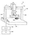
図1を参照すると、座標測定機械(「CMM」)100、デスクトップコンピュータ200、およびコントローラ102の形態で座標位置決め機械を構成する本発明の一実施形態による座標位置決め装置10が示されている。CMM100は、検査すべき物体、この場合ブリスク400を上に配置できるプラットホーム104と、ガントリとを備え、ガントリは、2つの直立部材108と、2つの直立部材108間に延びる横断部材110とを備える。ガントリは、コントローラ102の制御を受けてモータ(図示せず)によって1つの線形寸法(この場合、「y」軸と示す)でプラットホームに沿って動かすことができる。横断部材110はクイル112を保持し、クイル112は、コントローラ102の制御を受けてモータ(図示せず)によって、横断部材の長さ(この場合、「x」軸で示す)に沿って動かすことができ、また、y軸およびx軸に対して垂直に(すなわち、図示の「z」軸に沿って)動かすことができる。クイル112はヘッド114を保持し、ヘッド114は、次いでスタイラス118を有するプローブ116を保持し、スタイラス118は、細長いスタイラスシャフト120およびスタイラス先端部122を備える。記載の実施形態では、通常の場合と同様に、スタイラス先端部122は、CMM上の画定された点(たとえば、ヘッド114)に対するその寸法および場所が正確に知られるように較正されている(たとえば、較正アーティファクトを使用する)。シャフト120は較正されていないが、より詳細に以下で説明するように、その近似寸法が知られている。ヘッド114は、コントローラ102の制御を受けて第1の直交軸および第2の直交軸(図1の「A1」および「A2」)の周りのプローブ116、したがってスタイラス118の回転を容易にする軸受およびモータ(図示せず)を有することから、関節式に連結される。CMMは、コントローラ102に対する3つの線形自由度および2つの回転自由度のそれぞれにおけるガントリ、クイル112、およびプローブ116の位置を報告する位置エンコーダ(図示せず)を備え、それによってプローブの先端部122の位置を判定することを可能にする。
Referring to FIG. 1, a coordinate positioning apparatus 10 according to one embodiment of the present invention is shown that constitutes a coordinate positioning machine in the form of a coordinate measuring machine (“CMM”) 100, a
記載の実施形態では、プローブ116は、その静止位置からのスタイラスの偏向の程度を検出および報告する接触アナログプローブである(走査プローブとしても知られている)。理解されるように、プローブ116は、必ずしもアナログプローブである必要はない。たとえば、それは、プローブ116(具体的には、スタイラス118(より具体的には、スタイラス先端部))と物体106との間で接触が検出されたときに信号を発行するタッチトリガプローブとすることもできる。しかし、理解されるように、記載の実施形態では、アナログプローブは、単に縁部に沿ってアナログプローブスタイラスを走査させることによって、縁部の長さに沿った一連の測定を迅速に取得することを可能にするため、有利である。
In the described embodiment, the
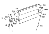
図2は、ブリスク400をより詳細に示す。理解されるように、そのようなブリスクは、タービンエンジン内で一般に使用される。見て取れるように、ブリスクは中心ハブ402を備え、中心ハブ402から複数の羽根404が放射状に延びる。通常、これらの羽根404は、製造中に中心ハブ402に溶接される。安全かつ効率的な動作を確実にするには、羽根404が正確に位置決めされることが最も重要である。具体的には、羽根404の前縁部406の位置、向き、寸法、および/または形状が重要であることが見出された。したがって、羽根404の前縁部の正確な測定が実行されることが重要である。もちろん、方法は、羽根上の後縁部、または実際には任意の他のタイプの物体の縁部(複数可)の測定にも等しく適用可能である。現在の技法は、アナログプローブを用いて羽根404の縁部を走査することを伴い、これは、スタイラス先端部122が縁部406の長さに沿って動かされるときに縁部の頂端408全体にわたってスタイラス先端部122を前後に掃引することを伴う可能性がある(図5にスタイラス先端部経路130で示す)。あるいは、縁部は、羽根の縁部の長さに沿って個別の場所で、縁部の複数の測定を行うことによって(羽根全体にわたってプローブを掃引することによって)測定される可能性もある。これらのタイプの測定を行うには、縁部全体にわたって(任意選択で、縁部に沿って)スタイラス先端部122の動きを制御するために、縁部の近似的な場所を知ることが必要である。しかし、羽根のそのような縁部を正確に測定することは特に困難であることも見出された。これは、中心ハブ402から離れて進むにつれて、製造公差によって、羽根の縁部の場所がその予期される場所から逸脱することが多いためである。これにより、スタイラス先端部122は羽根縁部から滑落し、および/または羽根縁部に衝突する。
FIG. 2 shows blisk 400 in more detail. As will be appreciated, such blisks are commonly used in turbine engines. As can be seen, the blisk comprises a
本発明は、たとえば縁部406の後の走査を支援するために羽根縁部406の場所を特定する素早く効率的な方法を提供する。図3に示すように、これは通常、ステップ302で、羽根縁部406の長さに沿って第1の一連の測定を取得することと、ステップ304で、羽根縁部406の長さに沿って第2の一連の測定を取得することと、ステップ306で、第1の一連の測定および第2の一連の測定を使用して縁部406の場所を識別することとを伴う。本発明の方法を使用して縁部の場所が特定された後、上述のように、また図5に示すように、ステップ308で、縁部406を測定することができる。
The present invention provides a quick and efficient method of locating the
これらのステップのそれぞれについて、図4を参照してより詳細に説明する。図4は、前縁部406を有する単一の羽根404の部分図を示す(簡単にするために分離して示す)。ステップ302で第1の一連の測定を取得することは、スタイラス118のシャフト120を使用して縁部406の頂端に沿って一連の測定を行うことを含む。理解されるように、記載の実施形態では、これは、プローブヘッド114からの向き情報およびプローブ116自体からのスタイラス偏向データを含むプローブの位置に関する測定情報を、CMM100から(たとえば、ガントリの様々な部分の位置を監視するエンコーダによって)取得することを伴う。具体的には、スタイラス118のシャフト120は、縁部の頂端408の一方の側面上で羽根404の長さに沿って走査される(走査経路を破線410で示す)。理解されるように、シャフト120の長さに沿ってどの点で接触が生じたかは知られておらず、羽根404とシャフト120との間の接触が何らかの点で生じたことのみが知られている。したがって、縁部の長さに沿って各測定点で特有の点が記録されるのではなく、羽根404とシャフト120との間の可能な接触点範囲が記録され、それによって第1の測定体積を提供する。第1の測定体積の一部が、第1の測定体積500として図4に示されている。次いで、羽根404に対するスタイラス118の角度が変化され、縁部の頂端408の反対側の第2の側面上でこのプロセスが繰り返されて(ステップ304)、第2の測定体積を取得する。この場合も、第2の測定体積の一部が、測定体積502として図4に示されている。これらの第1の測定体積および第2の測定体積は、シャフト120の形状および寸法の知識から(たとえば、CADモデルデータから)、またCMMおよびヘッド114の様々な軸上に提供される様々な位置エンコーダから判定される場所情報から判定される。
Each of these steps will be described in more detail with reference to FIG. FIG. 4 shows a partial view of a
図4に示すように、第1の測定体積500と第2の測定体積502は、他方の測定体積と重複および交差し、それによって交差体積504(第1の測定体積と第2の測定体積の重複領域に沿って全体に延び、図4では、視覚化を容易にするために、重複領域から延びる交差体積504が示されている)を画定する。記載の実施形態では、第1の測定体積と第2の測定体積は、縁部406の長さに沿って全体的に重複する。すなわち、第1の測定体積および第2の測定体積のそれぞれにおける第1の可能な接触点範囲および最後の可能な接触点範囲は、羽根の長さに沿って同じ長手方向の点で得られる。しかし、これは必ずしも当てはまる必要はなく、第1の測定と第2の測定は部分的にのみ重複することができる。たとえば、第1の体積および第2の体積における第1(および/または実際には、最後)の可能な接触点範囲は、羽根の長さに沿って異なる長手方向の点で得ることもできる。これは、たとえば図14に関連して以下で図示および説明する場合である。その場合、第1の測定体積と第2の測定体積は、それらが物体の長さに沿って重複するその領域に対してのみ交差するはずである。
As shown in FIG. 4, the
ステップ306で、交差体積504は次いで、縁部408の場所を判定するために使用される。特定の実施形態では、羽根の縁部の長さに沿って第1の測定体積500と第2の測定体積502との間の交差線が発見される。理解されるように、そのような交差線は、羽根の実際の縁部からずれる。羽根の実際の精密な寸法、場所、および向きがまだわからないため、本当の、実際のオフセットはわからない。実際、これが、これから測定すべきものである。この理由のため、理論上のオフセットが使用されるが、これは本当のオフセットの近似値である。この理論上のオフセットは、羽根が所定のコンピュータモデルによる理論上の羽根である場合に存在するはずのオフセットとすることができ、したがって、理論上のオフセットは、理論上の羽根、また羽根を測定するために使用されるスタイラスを示すデータから発見することができる。
At
理論上のオフセットと本当のオフセットとの間の差は、羽根が理論から異なる形態に依存する。これを例示するために、4つの場合について以下に説明する。 The difference between the theoretical offset and the true offset depends on the form in which the vanes differ from theory. To illustrate this, four cases are described below.
図8は、羽根がその理論上の場所に対して平行移動される状況を示す。理論上の羽根の場所を、この理論上の羽根上で行われると仮定した場合の試験走査で得られるスタイラスの場所とともに、破線の輪郭で示す。また、羽根の本当の場所を、実際の第1の測定および第2の測定で得られる本当のスタイラスの場所とともに、実線の輪郭で示す。実際の羽根と理論上の羽根の間の唯一の違いはその場所であるため、本当のオフセットと理論上のオフセットは同じである。したがって、第1の測定および第2の測定から導出された交差線に理論上のオフセットを適用することで、羽根の本当の縁部の場所を正確に特定する。 FIG. 8 shows the situation where the blade is translated relative to its theoretical location. The theoretical vane location is indicated by the dashed outline along with the stylus location obtained in the test scan assuming it is performed on the theoretical vane. In addition, the true location of the blade is indicated by a solid outline along with the actual stylus location obtained from the actual first and second measurements. Since the only difference between actual and theoretical blades is the location, the true and theoretical offsets are the same. Therefore, applying the theoretical offset to the intersecting line derived from the first measurement and the second measurement accurately identifies the location of the true edge of the blade.
図9は、測定すべき縁部に対して垂直な軸の周りでその理論上の場所に対して羽根が回転される状況を示す。縁部に沿って選択されたあらゆる交差区間で、この場合は、図8に関連して上記で説明および図示した状況に同一であると見なすことができる。したがって、縁部の本当の場所を、その長さに沿って特定することができる。 FIG. 9 shows the situation in which the blade is rotated relative to its theoretical location about an axis perpendicular to the edge to be measured. At every intersection section selected along the edge, this case can be considered identical to the situation described and illustrated above in connection with FIG. Thus, the true location of the edge can be identified along its length.
図10は、測定すべき縁部に対して平行な軸の周りでその理論上の場所に対して羽根が回転される状況を示す。前述のように、理論上の羽根の場所および実際の羽根の場所が、理論上のスタイラスの場所および実際のスタイラスの場所とともに示されている。この場合、理論上のオフセットを適用する結果、ワークピースの本当の縁部の場所にわずかな誤差が生じることがある。 FIG. 10 shows the situation where the blade is rotated relative to its theoretical location about an axis parallel to the edge to be measured. As mentioned above, the theoretical blade location and the actual blade location are shown along with the theoretical stylus location and the actual stylus location. In this case, applying a theoretical offset may result in a slight error in the true edge location of the workpiece.
図11は、羽根の材料条件が乏しく、たとえばワークピースの寸法が理論上の寸法とは異なる状況を示す。この場合、理論上のオフセットを適用する結果、ワークピースの本当の縁部の場所にわずかな誤差が生じることがある。 FIG. 11 shows a situation where the blade material conditions are poor, for example, the dimensions of the workpiece differ from the theoretical dimensions. In this case, applying a theoretical offset may result in a slight error in the true edge location of the workpiece.
図10および図11から理解されるように、前述の方法の結果、ワークピースの本当の縁部の場所を判定する際にわずかな誤差が生じることがある。しかし、この段階で判定すべきもののすべてが縁部の近似的な場所であり、その結果、後のステップでこれを使用して縁部の実際の測定を案内することができるため、これは許容可能である。図10および図11に示す場合でも、本発明の方法を使用すると、それはそのような縁部場所特定ステップを行わなかった場合より縁部の場所に関して多くの情報を提供するため、より良好な位置が得られる。具体的には、それは、任意の後の走査ステップがうまく実行されることを確実にするように、後の走査ステップでスタイラスが駆動される表面法線に関する情報を判定することを可能にする。 As can be seen from FIGS. 10 and 11, the aforementioned method may result in slight errors in determining the true edge location of the workpiece. However, this is acceptable because all that must be determined at this stage is the approximate location of the edge, so that it can be used in subsequent steps to guide the actual measurement of the edge. Is possible. Even in the cases shown in FIGS. 10 and 11, using the method of the present invention, it provides more information about the location of the edge than if no such edge location step was performed, so a better location. Is obtained. In particular, it makes it possible to determine information about the surface normals on which the stylus is driven in subsequent scanning steps to ensure that any subsequent scanning step is performed successfully.
縁部406の近似的な場所が判定された後、ステップ308で、縁部特徴の正確な測定を実行することが可能である。たとえば、これは、図5に示すようにそれが縁部の頂端408全体にわたって前後に掃引するときに縁部406の長さに沿ってスタイラス先端部122を走査させるようにスタイラス118を制御することを伴うことができる。次いで、後のプロセスで、たとえばその精密な場所および/または形状などの羽根404の縁部406の特定の特性を分析するために、この走査データを記憶および/または使用することができる。理解されるように、縁部の後の測定中に他の技法を使用することもできる。たとえば、縁部の長さに沿って異なる点で、縁部の頂端に関する複数の個別の走査を実行することができる。
After the approximate location of the
理解されるように、コンピュータ200は、そのような方法に対する命令を記憶し、コントローラ102にコマンドを発行することができ、コントローラ102は、次いでCMM100の様々な適当な部分上のモータを制御してプローブ116を動かす。さらに、コントローラ102は、CMM100上の様々なエンコーダからの位置データ、またプローブ116からのスタイラス偏向データを受け取る。コントローラ102は、このデータをコンピュータ200に渡し、コンピュータ200は、データを使用して、第1の測定体積500および第2の測定体積502を形成し(ステップ302および304で)、その後それらを処理して(ステップ306)、縁部の場所を特定する。次いで、コンピュータ200はまた、ステップ308で、場所が特定された縁部を使用して適した測定経路を生成し、この場合も、コントローラ102に命令を発行して、ステップ308で縁部の測定を行う。この場合も、コントローラ102は、コンピュータ200から受け取った命令に従って、CMM100の様々な適当な部分上のモータを適切に制御してプローブ116を動かし、縁部を測定する。さらに、コントローラ102は、この場合も、CMM100上の様々なエンコーダからの位置データ、またプローブ116からのスタイラス偏向データを受け取り、これらのデータをコンピュータ200に渡す。上記のように、コンピュータ200は、たとえばその場所および/または形状などの羽根404の縁部406の特定の特性を分析するために、後のプロセスでその測定データを記憶し、かつ/またはそれを使用することができる。
As will be appreciated, the
記載の実施形態では、ステップ308の縁部のより正確な測定は、ステップ302および304で第1の測定体積500および第2の測定体積502を取得したものと同じプローブ116およびスタイラス118によって実行される。具体的には、これは、較正されたスタイラス先端部122を使用して縁部を走査することを伴う。これは、たとえば(図5にスタイラス先端部経路130で示すように)スタイラス先端部122が縁部406の長さに沿って動かされるときに縁部の頂端408全体にわたってスタイラス先端部22を前後に走査させることによって行うことができる。あるいは、たとえば、上記のように、これは、羽根の縁部の長さに沿って個別の場所で、縁部の複数の測定を行うことによって(羽根の頂端408全体にわたってプローブを掃引することによって)行うことができる。
In the described embodiment, the more accurate measurement of the edge of
理解されるように、ステップ308で縁部の正確な測定に使用されるプローブは、ステップ302および304中に第1の測定および/または第2の測定を取得するために使用されるものと必ずしも同じである必要はない。実際には、完全に異なるタイプのプローブおよび/またはスタイラスを使用することもできる。たとえば、ステップ308で、タッチトリガプローブを使用して、縁部の頂端のいずれかの側面上で、縁部に沿って測定体積を取得することもできる。別の実施形態では、非接触プローブを使用して、ステップ308で測定を実行することもできる。
As will be appreciated, the probe used for accurate edge measurement in
上記の実施形態では、スタイラス118は、円筒形のシャフト120を有する。しかし、理解されるように、これは必ずしも当てはまる必要はなく、本発明は、他の形状のシャフトを用いて実施することもできる。たとえば、図6aおよび図6bはそれぞれ、トランペット状のシャフト150および円錐形のシャフト152(スタイラス先端部は省略されているが、理解されるように、スタイラスはスタイラス先端部を適切に含むことができる)を使用して取得した第1の一連の測定510、520および第2の一連の測定512、522と、そのような形状のシャフトを使用して取得した交差体積514、524とを示す。理解されるように、交差体積514、524は、羽根の縁部406を発見するために上述したものと同じ方法で使用することができる。
In the above embodiment, the
さらに、前述の実施形態では、第1の測定体積および第2の測定体積は、同じプローブおよびスタイラスを使用して取得される。しかし、これは必ずしも当てはまる必要はない。たとえば、プローブヘッド114上へ装填されたプローブ116および/またはスタイラス118は、第1の測定体積を取得することと第2の測定体積とを取得することとの間で変化させることができ、実際には、第1の測定体積を取得するために使用されるスタイラスシャフトの長さおよび/または形状は、第2の測定体積を取得するために使用されるものとは異なることができる。
Further, in the above-described embodiment, the first measurement volume and the second measurement volume are obtained using the same probe and stylus. However, this is not necessarily true. For example, the
前述の実施形態では、スタイラス118および羽根404の相対的な向きは、第1の測定体積500を取得することと第2の測定体積502を取得することとの間で変化される。しかし、これは必ずしも当てはまる必要はなく、たとえば、図7に示すように、スタイラスシャフト152の形状(この実施形態では、円錐形)は、スタイラス118の向きを変えることなく、第1の測定体積および第2の測定体積(図7には図示せず)を取得することを可能にする。
In the foregoing embodiment, the relative orientation of the
前述の実施形態では、第1の測定体積500は、縁部の頂端408の第1の側面上で取得され、第2の測定体積502は、縁部の頂端408の第2の側面上で取得される。しかし、これは必ずしも当てはまる必要はない。たとえば、図12aおよび図12bに示すように、縁部の頂端408の同じ側面上で、第1の測定体積530および第2の測定体積532を取得することができる。これはやはり、交差体積534を提供する。この実施形態は、羽根の回転方向が知られているときに縁部の平行移動位置の場所を特定するのに特に有用になる可能性がある。
In the foregoing embodiment, the
前述の実施形態では、第1の一連の測定および第2の一連の測定は、第1の測定体積500および第2の測定体積502を含む。しかし、これは必ずしも当てはまる必要はない。たとえば、図13を参照すると、第1の一連の測定および第2の一連の測定は、第1の測定「バンド」または「リボン」600および第2の測定「バンド」または「リボン」602を含むことができる。この実施形態では、一連の測定における測定データを生成するために、その外形ではなくシャフト120の軸の場所に関する知識が使用される。したがって、この実施形態では、第1の測定バンド600と第2の測定バンド602は、線604に沿って交差する。この交差線は、縁部の場所を識別するために上記のものと同じ方法で使用することができる。
In the foregoing embodiment, the first series of measurements and the second series of measurements include a
理解されるように、第1の一連の測定と第2の一連の測定が交差するが、これは必ずしも、第1の一連の測定内の個々の可能な接触点範囲が第2の一連の測定内の個々の可能な接触点範囲と交差することを意味する必要はない。たとえば、図14に示すように、縁部の第1の側面上で、縁部の長さに沿って個別の場所で3つの別個の可能な接触点範囲が取得され(たとえば、タッチトリガプローブによって、またはアナログ走査プローブを使用する縁部の走査の出力から取得される)、第1の一連の測定を形成する(枠600で示す)。図示を助けるために、図14には、羽根の長さに沿って横断面位置(b)、(d)、および(f)でこれらの3つの測定範囲が得られたことを示すように印が付けられている。これらの3つの個別の可能な接触点範囲は、細かい破線606によって示されている。さらに、縁部の第2の側面上で、縁部の長さに沿って個別の点で3つの可能な接触点範囲が取得され(たとえば、タッチトリガプローブによって取得される)、第2の一連の測定を形成する(枠602で示す)。これらの3つの個別の可能な接触点範囲は、粗い破線608によって示されている。図示を助けるために、図14には、羽根の長さに沿って横断面位置(a)、(c)、および(e)でこれらの3つの測定範囲が得られたことを示すように印が付けられている。見て取ることができるように、第1の一連の測定で取得したどの個々の測定範囲も、第2の一連の測定で取得した個々の測定範囲と交差しない。それにもかかわらず、第1の一連の測定と第2の一連の測定(これらの個別の可能な接触点測定範囲によって画定される)は、羽根の長さに沿って点(b)と点(e)との間で重複および交差する(第1の一連の測定と第2の一連の測定が交差する線は、線604によって示されている)。したがって、この場合、第1の一連の測定と第2の一連の測定との間のそれらの交差点を発見するように、羽根の長さに沿って共通の長手方向の位置に対して、それぞれの一連の測定内の測定範囲を外挿することができる。
As will be appreciated, the first series of measurements and the second series of measurements intersect, but this does not necessarily mean that the individual possible contact point ranges within the first series of measurements are the second series of measurements. It does not have to mean intersecting with the individual possible contact point ranges within. For example, as shown in FIG. 14, on the first side of the edge, three distinct possible contact point ranges are acquired at discrete locations along the length of the edge (eg, by a touch trigger probe). , Or obtained from the output of an edge scan using an analog scanning probe), forming a first series of measurements (indicated by box 600). To aid in illustration, FIG. 14 is marked to show that these three measurement ranges were obtained at cross-sectional positions (b), (d), and (f) along the length of the blade. Is attached. These three individual possible contact point ranges are indicated by fine dashed
さらに、前述の実施形態では、縁部は、2つの測定(または、一連の測定)間の交差点(または、線)からの「理論上のオフセット」を適用することによって発見される。しかし、測定データを使用して縁部の場所を特定する他の方法もある。たとえば、最良適合方法を使用して、縁部の場所を特定することができる。たとえば、図15(a)を参照すると、モデルが体積に接触しなければならないという制約に基づいて、羽根のコンピュータモデルに対する最良適合を実行するアルゴリズムに、シャフトによって描かれる体積(またはたとえば、中心線)を入力することができる。最良適合アルゴリズムは、その6つの自由度のいずれかまたはすべてにおいて、モデルの位置および向きを最適化することができる。それはまた、コンピュータモデルの理論上の材料条件からの材料条件の可能な変動を考慮に入れることができる。そのような最良適合アルゴリズムは当業者には知られており、最適化として知られている数学の部門が確立されている。理解されるように、アルゴリズムに提供できるデータが多ければ多いほど、適合がより良好になる可能性が高い。したがって、様々な向きでスタイラスを用いて羽根縁部を走査することが望ましいことがあり、たとえば図15(b)は、3つの走査が行われた場合に描かれる体積を示す。 Further, in the foregoing embodiment, the edge is found by applying a “theoretical offset” from the intersection (or line) between two measurements (or a series of measurements). However, there are other ways of using the measurement data to identify the edge location. For example, the best fit method can be used to identify the location of the edge. For example, referring to FIG. 15 (a), based on the constraint that the model must touch the volume, an algorithm that performs the best fit to the computer model of the wings is used to describe the volume (or centerline, for example) drawn by the shaft. ) Can be entered. The best fit algorithm can optimize the position and orientation of the model in any or all of its six degrees of freedom. It can also take into account possible variations in material conditions from the theoretical material conditions of the computer model. Such best-fit algorithms are known to those skilled in the art and a mathematical department known as optimization has been established. As will be appreciated, the more data that can be provided to the algorithm, the more likely it will be a better fit. Thus, it may be desirable to scan the blade edge with a stylus in various orientations, for example, FIG. 15 (b) shows the volume drawn when three scans are performed.
前述の実施形態では、第1の一連の測定と第2の一連の測定は互いに交差する。しかし、これは必ずしも当てはまる必要はなく、たとえば第1の一連の測定および第2の一連の測定を使用して縁部の場所を判定するために最良適合方法が使用される場合である。たとえば、図14を参照すると、最良適合アルゴリズムを使用して、互いに個々に交差しない2つの点、たとえば点(a)および(f)で取得した測定のみからまっすぐな縁部の場所を判定することができる。 In the foregoing embodiment, the first series of measurements and the second series of measurements intersect each other. However, this need not necessarily be the case, for example when the best fit method is used to determine the location of the edge using a first series of measurements and a second series of measurements. For example, referring to FIG. 14, the best fit algorithm is used to determine the location of a straight edge from only measurements taken at two points that do not individually intersect each other, eg, points (a) and (f). Can do.
記載の実施形態では、第1の一連の測定および第2の一連の測定について、2つの個別の測定手順、たとえば羽根の2つの個別の走査を実行することによって取得されたものとして説明されている。しかし、これは必ずしも当てはまる必要はない。たとえば、第1の一連の測定および第2の一連の測定は、羽根の1つの連続する走査を実行することによって取得することができ、これは、一方の方向に羽根の長さに沿ってプローブを走査し、次いで他方の方向に羽根の長さに沿って戻るという少なくとも1つのサイクルを含む。理解されるように、プローブおよび羽根の位置/向きは、個別のステップで、かつ/または連続して変化させることができる。 In the described embodiment, the first series of measurements and the second series of measurements are described as being obtained by performing two separate measurement procedures, eg, two separate scans of the blade. . However, this is not necessarily true. For example, a first series of measurements and a second series of measurements can be obtained by performing one successive scan of the blade, which is probed along the length of the blade in one direction. And then back along the length of the blade in the other direction. As will be appreciated, the position / orientation of the probes and vanes can be varied in discrete steps and / or continuously.
前述の実施形態では、場所を特定すべき特徴の近似的な形状および/または寸法が仮定された。しかし、これは必ずしも当てはまる必要はない。たとえば、測定を使用して、実質上知られていない形状および/または寸法の一部の形状および/または寸法を発見することができる(一般に、「知られていない部分の走査」と呼ばれる)。部分の各測定は、可能な接触点範囲を有するが、複数の測定を使用して、どれが場合によっては有効であるか、およびどれが明確に無効な接触点であるかを識別することができ、したがって、複数の測定から特徴の画像またはモデルを構築することが可能になる。異なる測定が交わりまたは交差する点は、有効な接触点と無効な接触点との間の境界を画定することができる。したがって、有効な接触点は、それぞれの異なる測定の可能な接触点の部分集合を含むことができる。たとえば、図15(a)を参照すると、それらの2つの測定のみから、物体の横断面形状および寸法は、2つの測定間の三角形の領域、すなわち有効な接触点によって画定される境界内に含むことができる形状になるはずであると判定することができる。図15(b)を参照すると、別の測定を追加することで、物体の実際の形状を判定するために使用できるより多くの情報が加えられることを見て取ることができる。理解されるように、取得される測定が多ければ多いほど、取得できる物体に関する形状および寸法情報の分解能がより高くなる。そのような方法は、たとえばタッチトリガプローブを使用して、特徴に関する複数の個別の点を得ることによって実施することができる。理解されるように、そのような方法は、アナログ走査プローブを使用して実行することができる。たとえば、アナログ走査プローブは、特徴の長さに沿って1つの点で、特徴全体にわたって引き回すことができる。任意選択で、方法は、スタイラスシャフトと特徴との間の異なる角度で(たとえば、特徴の長さに沿って延びる軸の周りで)特徴に沿って複数回(たとえば、前後に)スタイラスシャフトを走査させることを含むことができる。 In the previous embodiment, an approximate shape and / or size of the feature to be located was assumed. However, this is not necessarily true. For example, the measurement can be used to find some shapes and / or dimensions of substantially unknown shapes and / or dimensions (commonly referred to as “unknown part scans”). Each measurement of a part has a possible contact point range, but multiple measurements can be used to identify which are valid in some cases and which are clearly invalid contact points. Can thus build an image or model of the feature from multiple measurements. The point where the different measurements intersect or intersect can define the boundary between valid and invalid contact points. Thus, valid contact points can include a subset of each different possible measurement point. For example, referring to FIG. 15 (a), from just those two measurements, the cross-sectional shape and dimensions of the object fall within the triangular region between the two measurements, ie, the boundary defined by the effective contact points It can be determined that the shape should be able to. Referring to FIG. 15 (b), it can be seen that adding another measurement adds more information that can be used to determine the actual shape of the object. As will be appreciated, the more measurements that are acquired, the higher the resolution of the shape and dimensional information about the objects that can be acquired. Such a method can be implemented by obtaining a plurality of individual points relating to a feature, for example using a touch trigger probe. As will be appreciated, such a method can be performed using an analog scanning probe. For example, an analog scanning probe can be routed throughout the feature at one point along the length of the feature. Optionally, the method scans the stylus shaft multiple times (eg, back and forth) along the feature at different angles between the stylus shaft and the feature (eg, about an axis extending along the length of the feature). Can be included.
図15(c)は、アナログ走査プローブが5つの異なる角度方向で羽根の長さに沿って掃引されたそのような方法を示し、図15(c)は、羽根に沿った異なる掃引に対する羽根の長さに沿った1つの点における羽根の位置を示す。これは、たとえば異なる角度方向で複数の個別の掃引を実行することによって、またはたとえば、羽根に連続して接触したまま本質的に羽根の長さに沿ってシャフトを前後に擦ることによって実現することもできるはずである(角度方向は、各通過終了時に変化させることができ、またはたとえば、連続して変化させることができる)。見て取れるように、これは、羽根の長さに沿って各点に対してはるかに多数の測定を提供し、それによって、特徴の実際の形状により正確に類似するまで有効な接触点範囲を低減させることを可能にする。すなわち、5つの異なる測定に対する有効な接触点によって画定される境界または輪郭は、羽根の縁部のものに密接に類似する形状を有する。 FIG. 15 (c) shows such a method in which the analog scanning probe was swept along the length of the blade in five different angular directions, and FIG. 15 (c) shows the blade's for different sweeps along the blade. The position of the blade at one point along the length is shown. This can be achieved, for example, by performing a plurality of individual sweeps in different angular directions, or, for example, by rubbing the shaft back and forth essentially along the length of the blade while in continuous contact with the blade. (The angular direction can be changed at the end of each pass, or can be changed continuously, for example). As can be seen, this provides a much larger number of measurements for each point along the length of the blade, thereby reducing the effective contact point range until it more closely resembles the actual shape of the feature Make it possible. That is, the boundary or contour defined by valid contact points for five different measurements has a shape that closely resembles that of the blade edge.
複数の異なる走査から有効な接触点を使用できると判定することに基づいて、アーティファクトの場所を特定し、その形状および寸法を判定する前述の技法について、知られていない部分を走査することに関して説明されているが、理解されるように、そのような技法は、測定すべきアーティファクトの公称の形状が知られているときでも使用することができる。この場合、アーティファクトの公称モデルを使用して、アナログ走査プローブおよびアーティファクトの動きの相対的な進路を判定することができる。有効な走査点に基づいて(たとえば、対応して)測定された寸法/形状データと予期される公称モデルとを比較して、公称モデルからのあらゆる逸脱を判定することができる。 Describes the above technique for locating artifacts and determining their shape and dimensions based on determining that valid contact points can be used from multiple different scans with respect to scanning unknown parts However, as will be appreciated, such techniques can be used even when the nominal shape of the artifact to be measured is known. In this case, a nominal model of the artifact can be used to determine the relative path of movement of the analog scanning probe and the artifact. Measured dimension / shape data based on (for example, correspondingly) valid scan points can be compared with the expected nominal model to determine any deviation from the nominal model.
本発明を実施するためにプローブから取得した測定データを記録するには、様々な適当な方法がある。たとえば、前述の実施形態の多くでは、走査に沿って一連の位置に対してスタイラス体積データが記録されることが示唆されている。実際の体積データを記録することができ、あるいは、体積データをそこから判定できるプローブに関するデータを記録することができる。たとえば、スタイラス位置およびスタイラス向き情報を記録することができる。具体的には、たとえば、スタイラス向き情報は、プローブがその上に取り付けられる関節ヘッドの回転可能部分(複数可)の角度(複数可)の形態で記録することができる。スタイラス向き情報は、ベクトルとして記録することができる。スタイラス位置は、記録されたスタイラス先端部位置から判定することができる。任意選択で、クイル位置およびスタイラス先端部オフセット位置情報を記録することができる。 There are a variety of suitable methods for recording measurement data obtained from a probe to practice the present invention. For example, many of the previous embodiments suggest that stylus volume data is recorded for a series of positions along a scan. Actual volume data can be recorded, or data relating to probes from which volume data can be determined can be recorded. For example, stylus position and stylus orientation information can be recorded. Specifically, for example, the stylus orientation information can be recorded in the form of the angle (s) of the rotatable portion (s) of the joint head on which the probe is mounted. The stylus orientation information can be recorded as a vector. The stylus position can be determined from the recorded stylus tip position. Optionally, quill position and stylus tip offset position information can be recorded.
記載の実施形態では、座標位置決め機械は、直列CMMである(すなわち、3つの独立した直交運動軸によって3つの線形自由度が提供される)。しかし、理解されるように、本発明はまた、並列CMM、ロボットアームなど、他のタイプの座標位置決め機械の動きを制御するために使用することもできる。本発明はまた、専用のCMMだけではなく、工作機械などの座標位置決め機械とともに使用することができる。さらに、理解されるように、本発明はまた、デカルト座標位置決め機械および、極座標および球面座標位置決め機械などの非デカルト座標位置決め機械とともに使用するのに適している。 In the described embodiment, the coordinate positioning machine is a serial CMM (ie, three linear degrees of freedom are provided by three independent orthogonal motion axes). However, as will be appreciated, the present invention can also be used to control the movement of other types of coordinate positioning machines, such as parallel CMMs, robotic arms, and the like. The present invention can also be used with coordinate positioning machines such as machine tools as well as dedicated CMMs. Further, as will be appreciated, the present invention is also suitable for use with Cartesian coordinate positioning machines and non-Cartesian coordinate positioning machines such as polar and spherical coordinate positioning machines.
前述の実施形態では、プローブは、固定の位置で保持される部分に対して動かされ、かつ/または向きが変えられる。しかし、理解されるように、これは必ずしも当てはまる必要はなく、たとえばその部分は、ヘッドと同様に、またはヘッドの代わりに、動かし/向きを変えることができる。たとえば、部分は、摺動台および/または回転台上に取り付けることができる。 In the foregoing embodiment, the probe is moved and / or reoriented relative to the portion held in a fixed position. However, as will be appreciated, this need not necessarily be the case, for example, that portion can be moved / turned in the same way as the head or in place of the head. For example, the part can be mounted on a slide and / or a turntable.
前述の実施形態は、ブリスクの羽根に関する。しかし、理解されるように、これは必ずしも当てはまる必要はなく、理解されるように、本発明は、他のタイプの特徴およびアーティファクトにも等しく適用可能である。 The foregoing embodiments relate to blisk blades. However, as will be appreciated, this need not necessarily be the case, and as will be appreciated, the present invention is equally applicable to other types of features and artifacts.
Claims (19)
位置決め装置上に取り付けられた接触プローブのスタイラスを前記物体に接触させて前記物体の少なくとも第1の測定および第2の測定を取得するステップであって、各測定は、前記スタイラスの長さに沿った前記物体と前記スタイラスの一部との間の可能な接触点範囲をもたらし、したがって本質的に、前記長さに沿って前記物体の場所に不確実性を含む、取得するステップと、
前記少なくとも第1の測定および第2の測定に関連付けられた、知られているスタイラスの向きに関連する情報を使用することを含めて、前記少なくとも第1の測定および第2の測定を使用して、前記不確実性の程度を少なくとも低減させるステップとを含むことを特徴とする方法。 A method for identifying the location of an object feature,
Contacting a stylus of a contact probe mounted on a positioning device with the object to obtain at least a first measurement and a second measurement of the object, each measurement along the length of the stylus Obtaining a possible range of contact points between the object and a portion of the stylus, and thus essentially including uncertainty in the location of the object along the length;
Using the at least first measurement and the second measurement, including using information related to the known stylus orientation associated with the at least first measurement and the second measurement. And at least reducing the degree of uncertainty.
前記装置は、位置決め装置上に取り付けられた前記接触プローブの前記スタイラスを物体に接触させて、前記物体の少なくとも第1の測定および第2の測定を取得するように構成され、
各測定は、前記スタイラスの長さに沿った前記物体と前記スタイラスの一部との間の可能な接触点範囲をもたらし、したがって本質的に、前記長さに沿って前記物体の場所に不確実性を含み、
前記装置は、前記少なくとも第1の測定および第2の測定に関連付けられた、スタイラスの向きに関連する情報を使用することによって、前記少なくとも第1の測定および第2の測定を使用して、前記不確実性の程度を少なくとも低減させるように構成されることを特徴とする装置。 A device for locating object features comprising a contact probe having a stylus mounted on a coordinate positioning device;
The apparatus is configured to bring the stylus of the contact probe mounted on a positioning device into contact with an object to obtain at least a first measurement and a second measurement of the object;
Each measurement result in the contact point possible range between a portion of the stylus of the object and the stylus along the length, thus essentially uncertain location of the object along said length Including sex,
The apparatus uses the at least first and second measurements by using information related to stylus orientation associated with the at least first and second measurements, and An apparatus configured to at least reduce the degree of uncertainty.
接触プローブのスタイラスと前記物体との間の可能な接触点範囲をもたらす少なくとも第1の測定を行い、従って本質的に、前記スタイラスの長さに沿って前記物体の場所に不確実性を含む、測定を行うステップと、
前記接触プローブのスタイラスと前記物体との間の可能な接触点範囲をもたらす異なる第2の測定もまた、前記少なくとも第1の測定および第2の測定に関連付けられた、知られているスタイラスの向きに関連する情報と使用して、前記不確実性の程度を減少させるステップと
を含むことを特徴とする方法。 A method for identifying the location of an object,
Making at least a first measurement resulting in a possible contact point range between the stylus of the contact probe and the object, and thus essentially including uncertainty in the location of the object along the length of the stylus ; A step of measuring,
Wherein also different second measuring result in possible contact points ranges between stylus and the object of the contact probe also at least associated with the first measurement and the second measurement, the known stylus orientation Using the information associated with the method to reduce the degree of uncertainty.
Applications Claiming Priority (3)
| Application Number | Priority Date | Filing Date | Title |
|---|---|---|---|
| EP11250839.5 | 2011-10-06 | ||
| EP11250839 | 2011-10-06 | ||
| PCT/GB2012/000761 WO2013050729A1 (en) | 2011-10-06 | 2012-10-03 | Measurement method |
Publications (3)
| Publication Number | Publication Date |
|---|---|
| JP2014531602A JP2014531602A (en) | 2014-11-27 |
| JP2014531602A5 JP2014531602A5 (en) | 2015-11-12 |
| JP6199870B2 true JP6199870B2 (en) | 2017-09-20 |
Family
ID=47080732
Family Applications (1)
| Application Number | Title | Priority Date | Filing Date |
|---|---|---|---|
| JP2014533974A Active JP6199870B2 (en) | 2011-10-06 | 2012-10-03 | Measuring method |
Country Status (5)
| Country | Link |
|---|---|
| US (1) | US9366519B2 (en) |
| EP (1) | EP2764324B1 (en) |
| JP (1) | JP6199870B2 (en) |
| CN (1) | CN103842766B (en) |
| WO (1) | WO2013050729A1 (en) |
Families Citing this family (41)
| Publication number | Priority date | Publication date | Assignee | Title |
|---|---|---|---|---|
| EP2208354A4 (en) | 2007-10-10 | 2010-12-22 | Gerard Dirk Smits | Image projector with reflected light tracking |
| WO2012054231A2 (en) | 2010-10-04 | 2012-04-26 | Gerard Dirk Smits | System and method for 3-d projection and enhancements for interactivity |
| EP3144632B1 (en) | 2015-09-18 | 2021-08-11 | Hexagon Technology Center GmbH | Coordinate measuring machine having a camera |
| CN104995481B (en) | 2012-04-18 | 2018-05-01 | 瑞尼斯豪公司 | The method that feature is found out using lathe |
| EP3239653B1 (en) * | 2012-04-18 | 2018-11-21 | Renishaw plc | Method of measurement on a machine tool and corresponding machine tool |
| EP2839240B1 (en) * | 2012-04-18 | 2017-09-06 | Renishaw PLC | A method of analogue measurement scanning on a machine tool and corresponding machine tool apparatus |
| US9157721B1 (en) * | 2012-06-08 | 2015-10-13 | Beeline Company | Measuring system |
| US8971568B1 (en) * | 2012-10-08 | 2015-03-03 | Gerard Dirk Smits | Method, apparatus, and manufacture for document writing and annotation with virtual ink |
| US8910391B2 (en) * | 2013-01-24 | 2014-12-16 | Faro Technologies, Inc. | Non-articulated portable CMM |
| JP2015141139A (en) * | 2014-01-29 | 2015-08-03 | 株式会社ミツトヨ | Manual measurement device |
| US9810913B2 (en) | 2014-03-28 | 2017-11-07 | Gerard Dirk Smits | Smart head-mounted projection system |
| US9829305B2 (en) | 2014-05-14 | 2017-11-28 | Faro Technologies, Inc. | Metrology device and method of changing operating system |
| US9803969B2 (en) | 2014-05-14 | 2017-10-31 | Faro Technologies, Inc. | Metrology device and method of communicating with portable devices |
| US9903701B2 (en) * | 2014-05-14 | 2018-02-27 | Faro Technologies, Inc. | Articulated arm coordinate measurement machine having a rotary switch |
| US9746308B2 (en) | 2014-05-14 | 2017-08-29 | Faro Technologies, Inc. | Metrology device and method of performing an inspection |
| US9921046B2 (en) | 2014-05-14 | 2018-03-20 | Faro Technologies, Inc. | Metrology device and method of servicing |
| US9377533B2 (en) | 2014-08-11 | 2016-06-28 | Gerard Dirk Smits | Three-dimensional triangulation and time-of-flight based tracking systems and methods |
| GB201417771D0 (en) | 2014-10-08 | 2014-11-19 | Delcam Ltd | Measuring device and related methods |
| US10043282B2 (en) | 2015-04-13 | 2018-08-07 | Gerard Dirk Smits | Machine vision for ego-motion, segmenting, and classifying objects |
| US10545019B2 (en) | 2015-04-14 | 2020-01-28 | Hexagon Metrology, Inc. | CMM probe path controller and method |
| CN107532930B (en) * | 2015-04-29 | 2021-07-30 | 瑞尼斯豪公司 | Method for determining subdivision errors |
| US10107654B2 (en) * | 2015-09-02 | 2018-10-23 | Nikon Corporation | Rotary probe head |
| US9753126B2 (en) | 2015-12-18 | 2017-09-05 | Gerard Dirk Smits | Real time position sensing of objects |
| WO2017121993A1 (en) * | 2016-01-15 | 2017-07-20 | Renishaw Plc | Model building from inspection data |
| US9813673B2 (en) | 2016-01-20 | 2017-11-07 | Gerard Dirk Smits | Holographic video capture and telepresence system |
| EP3255373B1 (en) * | 2016-06-09 | 2019-04-24 | Klingelnberg AG | Contact measurement on the tooth flank of a gear wheel |
| US10286556B2 (en) * | 2016-10-16 | 2019-05-14 | The Boeing Company | Method and apparatus for compliant robotic end-effector |
| EP3532863A4 (en) | 2016-10-31 | 2020-06-03 | Gerard Dirk Smits | Fast scanning lidar with dynamic voxel probing |
| US10261183B2 (en) | 2016-12-27 | 2019-04-16 | Gerard Dirk Smits | Systems and methods for machine perception |
| WO2018209096A2 (en) | 2017-05-10 | 2018-11-15 | Gerard Dirk Smits | Scan mirror systems and methods |
| DE102017213555A1 (en) * | 2017-08-04 | 2019-02-07 | Siemens Aktiengesellschaft | An apparatus and method for location-based location of a location on a surface of an object |
| US10591605B2 (en) | 2017-10-19 | 2020-03-17 | Gerard Dirk Smits | Methods and systems for navigating a vehicle including a novel fiducial marker system |
| CN107907091B (en) * | 2017-12-14 | 2023-06-02 | 山东科技大学 | Measuring device and method for measuring waveform error of lip of waveform lip oil seal mold core |
| WO2019148214A1 (en) | 2018-01-29 | 2019-08-01 | Gerard Dirk Smits | Hyper-resolved, high bandwidth scanned lidar systems |
| JP6670896B2 (en) * | 2018-08-10 | 2020-03-25 | 本田技研工業株式会社 | Measurement jig |
| CN109341478B (en) * | 2018-11-14 | 2020-10-09 | 中国航发动力股份有限公司 | Turbine blade size measuring device and measuring method |
| DE102019205145B4 (en) * | 2019-04-10 | 2022-06-15 | Carl Zeiss Industrielle Messtechnik Gmbh | Aligning components relative to a coordinate measuring machine |
| FR3097323B1 (en) * | 2019-06-13 | 2021-07-02 | Safran Aircraft Engines | Method of checking a turbomachine part by means of a three-dimensional measuring machine |
| US11372320B2 (en) | 2020-02-27 | 2022-06-28 | Gerard Dirk Smits | High resolution scanning of remote objects with fast sweeping laser beams and signal recovery by twitchy pixel array |
| JP2022075107A (en) * | 2020-11-06 | 2022-05-18 | 株式会社ミツトヨ | Form measuring device and abnormality detection method |
| US11644294B2 (en) | 2021-01-29 | 2023-05-09 | Autodesk, Inc. | Automatic generation of probe path for surface inspection and part alignment |
Family Cites Families (20)
| Publication number | Priority date | Publication date | Assignee | Title |
|---|---|---|---|---|
| US3318009A (en) * | 1964-12-10 | 1967-05-09 | Ford Motor Co | Blade examining apparatus |
| US4166323A (en) * | 1973-09-14 | 1979-09-04 | Maag Gear-Wheel & Machine Co. Ltd. | Gear tester for profile and lead testing |
| US4043046A (en) * | 1976-03-25 | 1977-08-23 | Thomas Charles F | Edge finder probe |
| US4612622A (en) * | 1983-07-12 | 1986-09-16 | United Technologies Corporation | Probe for coordinate measuring machine |
| GB8618152D0 (en) * | 1986-07-25 | 1986-09-03 | Renishaw Plc | Co-ordinate measuring |
| US5189806A (en) * | 1988-12-19 | 1993-03-02 | Renishaw Plc | Method of and apparatus for scanning the surface of a workpiece |
| US5510977A (en) | 1994-08-02 | 1996-04-23 | Faro Technologies Inc. | Method and apparatus for measuring features of a part or item |
| JPH1062150A (en) * | 1996-08-19 | 1998-03-06 | Mitsutoyo Corp | Ball probe and coordinate measuring apparatus using ball probe |
| US6460261B1 (en) * | 1999-11-18 | 2002-10-08 | Mitutoyo Corporation | V-groove shape measuring method and apparatus by using rotary table |
| GB0220158D0 (en) * | 2002-08-30 | 2002-10-09 | Renishaw Plc | Method of scanning |
| GB0329098D0 (en) | 2003-12-16 | 2004-01-21 | Renishaw Plc | Method of calibrating a scanning system |
| JP4782990B2 (en) * | 2004-05-31 | 2011-09-28 | 株式会社ミツトヨ | Surface scanning measuring device, surface scanning measuring method, surface scanning measuring program, and recording medium |
| GB0508273D0 (en) * | 2005-04-25 | 2005-06-01 | Renishaw Plc | Method for scanning the surface of a workpiece |
| NL1030138C2 (en) * | 2005-10-07 | 2007-04-11 | Ibs Prec Engineering B V | Measuring assembly and method for determining the mutual position of machine parts. |
| GB0605796D0 (en) * | 2006-03-23 | 2006-05-03 | Renishaw Plc | Apparatus and method of measuring workpieces |
| GB0608235D0 (en) | 2006-04-26 | 2006-06-07 | Renishaw Plc | Differential calibration |
| GB0713639D0 (en) * | 2007-07-13 | 2007-08-22 | Renishaw Plc | Error correction |
| JP5684712B2 (en) * | 2008-10-29 | 2015-03-18 | レニショウ パブリック リミテッド カンパニーRenishaw Public Limited Company | Method for coordinate measuring system |
| EP2839240B1 (en) * | 2012-04-18 | 2017-09-06 | Renishaw PLC | A method of analogue measurement scanning on a machine tool and corresponding machine tool apparatus |
| JP6113963B2 (en) * | 2012-04-26 | 2017-04-12 | 株式会社ミツトヨ | Shape measuring method and shape measuring apparatus |
-
2012
- 2012-10-03 WO PCT/GB2012/000761 patent/WO2013050729A1/en active Application Filing
- 2012-10-03 EP EP12778770.3A patent/EP2764324B1/en active Active
- 2012-10-03 US US14/350,264 patent/US9366519B2/en active Active
- 2012-10-03 CN CN201280049195.8A patent/CN103842766B/en active Active
- 2012-10-03 JP JP2014533974A patent/JP6199870B2/en active Active
Also Published As
| Publication number | Publication date |
|---|---|
| CN103842766A (en) | 2014-06-04 |
| CN103842766B (en) | 2017-05-24 |
| EP2764324A1 (en) | 2014-08-13 |
| US20140215841A1 (en) | 2014-08-07 |
| US9366519B2 (en) | 2016-06-14 |
| JP2014531602A (en) | 2014-11-27 |
| WO2013050729A1 (en) | 2013-04-11 |
| EP2764324B1 (en) | 2019-03-27 |
Similar Documents
| Publication | Publication Date | Title |
|---|---|---|
| JP6199870B2 (en) | Measuring method | |
| JP6013533B2 (en) | Surface sensor offset | |
| JP5684712B2 (en) | Method for coordinate measuring system | |
| JP5350216B2 (en) | Processed product measuring apparatus and measuring method | |
| JP5998058B2 (en) | Correction of errors in measured values obtained using a coordinate positioning device | |
| EP1926969B1 (en) | Method and apparatus for measuring wall thicknesses of objects | |
| JP5665270B2 (en) | Method for scanning the surface of a workpiece | |
| JP5575635B2 (en) | Surface measuring apparatus and method | |
| EP1579168B1 (en) | Workpiece inspection method and apparatus | |
| JP6583730B2 (en) | CMM measuring method, measuring control device, and measuring program | |
| Heo et al. | Computer-aided measurement plan for an impeller on a coordinate measurement machine with a rotating and tilting probe | |
| EP3189302B1 (en) | Coordinate measuring method and apparatus for inspecting workpieces, comprising generating measurement correction values using a reference shape that is known not to deviate substantially from a perfect form | |
| CN113334383B (en) | Robot tail end tool offset calibration method based on line laser measuring instrument | |
| JP3189500U (en) | Method and apparatus for measuring the thickness of an object |
Legal Events
| Date | Code | Title | Description |
|---|---|---|---|
| A521 | Request for written amendment filed |
Free format text: JAPANESE INTERMEDIATE CODE: A523 Effective date: 20150924 |
|
| A621 | Written request for application examination |
Free format text: JAPANESE INTERMEDIATE CODE: A621 Effective date: 20150924 |
|
| A977 | Report on retrieval |
Free format text: JAPANESE INTERMEDIATE CODE: A971007 Effective date: 20160830 |
|
| A131 | Notification of reasons for refusal |
Free format text: JAPANESE INTERMEDIATE CODE: A131 Effective date: 20160906 |
|
| A601 | Written request for extension of time |
Free format text: JAPANESE INTERMEDIATE CODE: A601 Effective date: 20161205 |
|
| A521 | Request for written amendment filed |
Free format text: JAPANESE INTERMEDIATE CODE: A523 Effective date: 20170306 |
|
| TRDD | Decision of grant or rejection written | ||
| A01 | Written decision to grant a patent or to grant a registration (utility model) |
Free format text: JAPANESE INTERMEDIATE CODE: A01 Effective date: 20170725 |
|
| A61 | First payment of annual fees (during grant procedure) |
Free format text: JAPANESE INTERMEDIATE CODE: A61 Effective date: 20170824 |
|
| R150 | Certificate of patent or registration of utility model |
Ref document number: 6199870 Country of ref document: JP Free format text: JAPANESE INTERMEDIATE CODE: R150 |
|
| R250 | Receipt of annual fees |
Free format text: JAPANESE INTERMEDIATE CODE: R250 |
|
| R250 | Receipt of annual fees |
Free format text: JAPANESE INTERMEDIATE CODE: R250 |
|
| R250 | Receipt of annual fees |
Free format text: JAPANESE INTERMEDIATE CODE: R250 |
|
| R250 | Receipt of annual fees |
Free format text: JAPANESE INTERMEDIATE CODE: R250 |