JP6345877B2 - Valve timing control device for internal combustion engine - Google Patents
Valve timing control device for internal combustion engine Download PDFInfo
- Publication number
- JP6345877B2 JP6345877B2 JP2017521754A JP2017521754A JP6345877B2 JP 6345877 B2 JP6345877 B2 JP 6345877B2 JP 2017521754 A JP2017521754 A JP 2017521754A JP 2017521754 A JP2017521754 A JP 2017521754A JP 6345877 B2 JP6345877 B2 JP 6345877B2
- Authority
- JP
- Japan
- Prior art keywords
- camshaft
- driven
- rotating body
- timing control
- valve timing
- Prior art date
- Legal status (The legal status is an assumption and is not a legal conclusion. Google has not performed a legal analysis and makes no representation as to the accuracy of the status listed.)
- Active
Links
Images


Classifications
-
- F—MECHANICAL ENGINEERING; LIGHTING; HEATING; WEAPONS; BLASTING
- F01—MACHINES OR ENGINES IN GENERAL; ENGINE PLANTS IN GENERAL; STEAM ENGINES
- F01L—CYCLICALLY OPERATING VALVES FOR MACHINES OR ENGINES
- F01L1/00—Valve-gear or valve arrangements, e.g. lift-valve gear
- F01L1/34—Valve-gear or valve arrangements, e.g. lift-valve gear characterised by the provision of means for changing the timing of the valves without changing the duration of opening and without affecting the magnitude of the valve lift
- F01L1/344—Valve-gear or valve arrangements, e.g. lift-valve gear characterised by the provision of means for changing the timing of the valves without changing the duration of opening and without affecting the magnitude of the valve lift changing the angular relationship between crankshaft and camshaft, e.g. using helicoidal gear
- F01L1/352—Valve-gear or valve arrangements, e.g. lift-valve gear characterised by the provision of means for changing the timing of the valves without changing the duration of opening and without affecting the magnitude of the valve lift changing the angular relationship between crankshaft and camshaft, e.g. using helicoidal gear using bevel or epicyclic gear
-
- F—MECHANICAL ENGINEERING; LIGHTING; HEATING; WEAPONS; BLASTING
- F01—MACHINES OR ENGINES IN GENERAL; ENGINE PLANTS IN GENERAL; STEAM ENGINES
- F01L—CYCLICALLY OPERATING VALVES FOR MACHINES OR ENGINES
- F01L1/00—Valve-gear or valve arrangements, e.g. lift-valve gear
- F01L1/02—Valve drive
- F01L1/04—Valve drive by means of cams, camshafts, cam discs, eccentrics or the like
- F01L1/047—Camshafts
-
- F—MECHANICAL ENGINEERING; LIGHTING; HEATING; WEAPONS; BLASTING
- F01—MACHINES OR ENGINES IN GENERAL; ENGINE PLANTS IN GENERAL; STEAM ENGINES
- F01L—CYCLICALLY OPERATING VALVES FOR MACHINES OR ENGINES
- F01L1/00—Valve-gear or valve arrangements, e.g. lift-valve gear
- F01L1/46—Component parts, details, or accessories, not provided for in preceding subgroups
-
- F—MECHANICAL ENGINEERING; LIGHTING; HEATING; WEAPONS; BLASTING
- F01—MACHINES OR ENGINES IN GENERAL; ENGINE PLANTS IN GENERAL; STEAM ENGINES
- F01L—CYCLICALLY OPERATING VALVES FOR MACHINES OR ENGINES
- F01L13/00—Modifications of valve-gear to facilitate reversing, braking, starting, changing compression ratio, or other specific operations
- F01L2013/10—Auxiliary actuators for variable valve timing
- F01L2013/103—Electric motors
-
- F—MECHANICAL ENGINEERING; LIGHTING; HEATING; WEAPONS; BLASTING
- F01—MACHINES OR ENGINES IN GENERAL; ENGINE PLANTS IN GENERAL; STEAM ENGINES
- F01L—CYCLICALLY OPERATING VALVES FOR MACHINES OR ENGINES
- F01L2250/00—Camshaft drives characterised by their transmission means
- F01L2250/02—Camshaft drives characterised by their transmission means the camshaft being driven by chains
-
- F—MECHANICAL ENGINEERING; LIGHTING; HEATING; WEAPONS; BLASTING
- F01—MACHINES OR ENGINES IN GENERAL; ENGINE PLANTS IN GENERAL; STEAM ENGINES
- F01L—CYCLICALLY OPERATING VALVES FOR MACHINES OR ENGINES
- F01L2301/00—Using particular materials
-
- F—MECHANICAL ENGINEERING; LIGHTING; HEATING; WEAPONS; BLASTING
- F01—MACHINES OR ENGINES IN GENERAL; ENGINE PLANTS IN GENERAL; STEAM ENGINES
- F01L—CYCLICALLY OPERATING VALVES FOR MACHINES OR ENGINES
- F01L2303/00—Manufacturing of components used in valve arrangements
-
- F—MECHANICAL ENGINEERING; LIGHTING; HEATING; WEAPONS; BLASTING
- F01—MACHINES OR ENGINES IN GENERAL; ENGINE PLANTS IN GENERAL; STEAM ENGINES
- F01L—CYCLICALLY OPERATING VALVES FOR MACHINES OR ENGINES
- F01L2820/00—Details on specific features characterising valve gear arrangements
- F01L2820/03—Auxiliary actuators
- F01L2820/032—Electric motors
-
- F—MECHANICAL ENGINEERING; LIGHTING; HEATING; WEAPONS; BLASTING
- F01—MACHINES OR ENGINES IN GENERAL; ENGINE PLANTS IN GENERAL; STEAM ENGINES
- F01L—CYCLICALLY OPERATING VALVES FOR MACHINES OR ENGINES
- F01L2820/00—Details on specific features characterising valve gear arrangements
- F01L2820/04—Sensors
- F01L2820/042—Crankshafts position
-
- F—MECHANICAL ENGINEERING; LIGHTING; HEATING; WEAPONS; BLASTING
- F01—MACHINES OR ENGINES IN GENERAL; ENGINE PLANTS IN GENERAL; STEAM ENGINES
- F01L—CYCLICALLY OPERATING VALVES FOR MACHINES OR ENGINES
- F01L2820/00—Details on specific features characterising valve gear arrangements
- F01L2820/04—Sensors
- F01L2820/044—Temperature
Landscapes
- Engineering & Computer Science (AREA)
- Mechanical Engineering (AREA)
- General Engineering & Computer Science (AREA)
- Valve Device For Special Equipments (AREA)
Description
本発明は、吸気弁や排気弁の開閉時期を制御する内燃機関のバルブタイミング制御装置に関する。 The present invention relates to a valve timing control device for an internal combustion engine that controls opening and closing timings of intake valves and exhaust valves.
内燃機関のバルブタイミング制御装置としては、本出願人が先に出願した以下の特許文献1に記載されているものが知られている。
As a valve timing control device for an internal combustion engine, a device described in the following
このバルブタイミング制御装置は、タイミングスプロケットに一体的の設けられた電動モータを有し、該電動モータの回転力を、タイミングスプロケットの内部に設けられた減速機構を介して従動部材に伝達することによってクランクシャフトに対するカムシャフトの相対回転位相を変換して吸気弁や排気弁の開閉タイミングを制御するようになっている。 This valve timing control device has an electric motor provided integrally with the timing sprocket, and transmits the rotational force of the electric motor to a driven member via a speed reduction mechanism provided inside the timing sprocket. The opening / closing timing of the intake valve and the exhaust valve is controlled by converting the relative rotation phase of the camshaft with respect to the crankshaft.
前記タイミングスプロケットのカムシャフト側の後端面には、円環状のストッパプレートがボルト固定されている一方、前記ストッパプレートの内周側には、ストッパプレートと協働して前記タイミングスプロケットとカムシャフトの最大相対回転位置を規制する円盤状のアダプタが設けられている。 An annular stopper plate is bolted to the rear end surface of the timing sprocket on the camshaft side. On the inner peripheral side of the stopper plate, the timing sprocket and the camshaft are in cooperation with the stopper plate. A disk-shaped adapter that regulates the maximum relative rotational position is provided.
このアダプタは、前記従動部材の固定端部とカムシャフトとの間に介装されて、外端面の内周部に前記カムシャフトの軸方向一端面が当接しつつ前記従動部材側から挿入されたカムボルトによって、共締め固定されるようになっている。 This adapter is interposed between the fixed end of the driven member and the camshaft, and is inserted from the driven member side while the one axial end surface of the camshaft is in contact with the inner peripheral portion of the outer end surface. It is fixed together by cam bolts.
ところで、前記バルブタイミング制御装置にあっては、エンジンルーム内への良好な搭載性を確保するために、装置全体の軸方向の長さを可及的に短尺化することが望まれている。 By the way, in the said valve timing control apparatus, in order to ensure the favorable mounting property in an engine room, it is desired to shorten the length of the whole apparatus of the axial direction as much as possible.
しかしながら、前記従来のバルブタイミング制御装置にあっては、軸方向の短尺化については考慮されておらず、特に、カムシャフトの軸方向の一端部と従動部材の固定端部との間にアダプタが介在されていることから、このアダプタの肉厚分だけ軸方向の長さが長くなってしまう。 However, in the conventional valve timing control device, the reduction in the axial direction is not considered, and in particular, an adapter is provided between one end portion of the camshaft in the axial direction and the fixed end portion of the driven member. Since it is interposed, the length in the axial direction is increased by the thickness of the adapter.
本発明は、前記従来の技術的課題に鑑みて案出されたもので、カムシャフトと装置の相対関係における軸方向の長さを十分に短尺化できる内燃機関のバルブタイミング制御装置を提供することを目的としている。 The present invention has been devised in view of the above-described conventional technical problem, and provides a valve timing control device for an internal combustion engine that can sufficiently shorten the axial length of the relative relationship between the camshaft and the device. It is an object.
本発明は、とりわけ、従動回転体は、カムシャフトの軸方向一端部が対向する位置に第1凹部が形成されている一方、固定部材は、前記カムシャフトの軸方向一端部と対向する位置に、該カムシャフトの一端部が軸方向から嵌合する第2凹部が形成されていると共に、前記第1凹部に嵌合する凸部を有することを特徴としている。 In the present invention, in particular, the driven rotor has a first recess formed at a position where one axial end of the camshaft faces, while the fixing member is located at a position facing the one axial end of the camshaft. The camshaft is characterized in that a second recess is formed in which one end portion of the camshaft is fitted from the axial direction, and a convex portion is fitted in the first recess.
この発明によれば、カムシャフトとの相対関係で装置の軸方向の長さを十分に短くすることができる。 According to the present invention, the axial length of the device can be sufficiently shortened due to the relative relationship with the camshaft.
以下、本発明に係る内燃機関のバルブタイミング制御装置の実施形態を図面に基づいて説明する。なお、この実施形態では、吸気弁側のバルブタイミング制御装置に適用したものであるが、排気弁側にも適用可能である。 DESCRIPTION OF EMBODIMENTS Hereinafter, an embodiment of a valve timing control device for an internal combustion engine according to the present invention will be described with reference to the drawings. Although this embodiment is applied to the valve timing control device on the intake valve side, it can also be applied to the exhaust valve side.
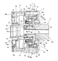
前記バルブタイミング制御装置は、図1及び図3に示すように、内燃機関のクランクシャフトによって回転駆動する駆動回転体であるタイミングスプロケット1と、シリンダヘッド01上に軸受02を介して回転自在に支持されていると共に、前記タイミングスプロケット1に相対回転自在に設けられ、該タイミングスプロケット1から伝達された回転力によって回転するカムシャフト2と、前記タイミングスプロケット1とカムシャフト2との間に配置されて、機関運転状態に応じて両者1,2の相対回転位相を変更する位相変更機構3と、該位相変更機構3の前端に配置されたカバー部材4と、を備えている。
As shown in FIGS. 1 and 3, the valve timing control device is rotatably supported on a
前記タイミングスプロケット1は、図2に示すように、全体が鉄系金属によって環状一体に形成されて、外径が比較的小径状に形成されたスプロケット本体1aと、該スプロケット本体1aの外周に一体に設けられて、巻回された図外のタイミングチェーンを介してクランクシャフトからの回転力を受けるギア部1bと、前記スプロケット本体1aの前端側に一体に設けられた内歯構成部19と、から構成されている。
As shown in FIG. 2, the
前記スプロケット本体1aは、内周面が段差径状に形成されていると共に、内周面の軸方向の前記カムシャフト2側である一端側に開口した円環溝状の外輪固定面60が切欠形成されている。この外輪固定面60は、軸方向の内端側に段差面60aが軸直角方向に沿って形成されている。
The
前記内歯構成部19は、前記スプロケット本体1aの前端部外周側に一体に設けられ、位相変更機構3の前方へ延出した円筒状に形成されていると共に、内周には波形状の複数の内歯19aが形成されている。
The
また、このタイミングスプロケット1は、スプロケット本体1aと前記カムシャフト2の軸方向の一端部2aに設けられた後述する従動回転体である従動部材9との間に、1つの大径ボールベアリング43が介装されており、この大径ボールベアリング43によって、タイミングスプロケット1が前記従動部材9(カムシャフト2)に相対回転自在に軸受けされている。
The
前記大径ボールベアリング43は、図2及び図3にも示すように、外輪43a及び内輪43bと、該両輪の間に介装されたボール43cと、該ボール43cを保持するケージ43dと、から主として構成されている。
2 and 3, the large-diameter ball bearing 43 includes an
前記外輪43aは、外周面が前記スプロケット本体1aの前記外輪固定面60の内周面に軸方向から圧入固定されて、外輪固定面60の内側段差面60aに突き当たって軸方向の位置決めがされるようになっている。
The
前記内輪43bは、前記従動部材9の後述する固定端部9aの外周側に形成された円環状の内輪固定面62の外周面に軸方向から圧入固定されており、この内輪固定面62の内側段差面62aに突き当たって軸方向の位置決めがされるようになっている。
The
さらに、前記スプロケット本体1aの内歯構成部19と反対側の後端面には、ストッパプレート61が固定されている。このストッパプレート61は、図1及び図5に示すように、金属板材によって円環状に形成され、外径が前記スプロケット本体1aの外径とほぼ同一に設定されていると共に、内径が前記大径ボールベアリング43の外輪43aの内径よりも小さい径に設定されている。内周部61aが前記外輪43aの軸方向の外端面に当接配置されている。
Further, a
前記ストッパプレート61の内周部61aの内周縁所定位置には、図5の径方向内側、つまり中心軸方向に向かって突出した突起部61bが一体に設けられている。
At a predetermined position on the inner peripheral edge of the inner
この突起部61bは、図5に示すように、ほぼ扇状に形成されて、先端縁61cが後述するアダプタ63の溝部であるストッパ凹溝64bの円弧状内周面に沿った円弧状に形成されている。さらに、前記ストッパプレート61の外周部には、各ボルト7が挿通する6つのボルト挿通孔61dが周方向の等間隔位置に貫通形成されている。
As shown in FIG. 5, the
前記スプロケット本体1a(内歯構成部19)及びストッパプレート61の各外周部には、それぞれボルト挿通孔1c、61dが周方向のほぼ等間隔位置に6つ貫通形成されている。
Six
前記内歯構成部19の外端面には、後述する電動モータ8のモータハウジング5が前記各ボルト7を介して軸方向から結合されている。
A motor housing 5 of an
このモータハウジング5は、図1に示すように、鉄系金属材をプレス成形によって有底筒状に形成されたハウジング本体5aと、該ハウジング本体5aの前端開口を封止する給電プレート11と、を備えている。
As shown in FIG. 1, the motor housing 5 includes a
前記ハウジング本体5aは、外径が前記スプロケット本体1aの外径と同じく比較的小径に形成され、後端側に円板状の隔壁5bを有している。この隔壁5bのほぼ中央には、後述するモータ出力軸13及び偏心軸部39が挿通される大径な軸挿通孔5cが形成されていると共に、この軸挿通孔5cの孔縁に径方向内側へ突出した円筒状の延出部5dが一体に設けられている。また、前記隔壁5bの外周部の内部には、雌ねじ孔6が軸方向に沿って形成されている。
The
前記雌ねじ孔6は、各ボルト挿通孔1c、61dと対応した位置に形成されており、これらに挿通した6本のボルト7によって前記タイミングスプロケット1(内歯構成部19)とストッパプレート61及びハウジング本体5aが軸方向から共締め固定されている。
The
前記カムシャフト2は、外周に図外の吸気弁を開作動させる一気筒当たり2つの駆動カムを有していると共に、軸方向の一端部2aに固定部材であるアダプタ63を介して従動回転体である従動部材9がカムボルト10によって軸方向から共締め固定されている。
The
前記従動部材9は、鉄系金属によって一体に形成され、図1及び図2に示すように、後端側(カムシャフト2側)に形成された円板状の固定端部9aと、該固定端部9aの内周前端面から軸方向へ突出した円筒部9bと、前記固定端部9aの外周部に一体に形成されて、複数のローラ48を保持する保持部材である円筒状の保持器41と、から構成されている。
The driven
前記固定端部9aは、外側面9cがカムシャフト2の一端部2aの前端面側に対向配置され、この外側面9cのほぼ中央位置に第1凹部である第1嵌合溝9dが形成されている。この第1嵌合溝9dは、円盤状に形成されて、その内径がカムシャフト2の一端部2aの外径よりも大きく形成されていると共に、深さDが前記アダプタ63の肉厚とほぼ同じ寸法に設定されている。また、この第1嵌合溝9dの内周面は、前記大径ボールベアリング43の外輪43bに径方向で重なる位置に配置されている。
The
前記円筒部9bは、図1に示すように、中央に前記カムボルト10の軸部10bが挿通される挿通孔9eが貫通形成されていると共に、外周側にはニードルベアリング38と小径ボールベアリング37がそれぞれ並列状態に設けられている。
As shown in FIG. 1, the
前記カムボルト10は、図1に示すように、頭部10aの軸方向端面が小径ボールベアリング37の内輪を軸方向から支持していると共に、軸部10bの外周に前記カムシャフト2の端部から内部軸方向に形成された雌ねじ2cに螺着する雄ねじ10cが形成されている。
As shown in FIG. 1, the
前記アダプタ63は、図1〜図3及び図6A,Bに示すように、一定の肉厚を有する円盤状の金属板をプレス成形によって縦断面ほぼクランク状に折曲形成され、フランジ状の外周部64と、電動モータ8方向へ突出した有底円筒状の中央側の内周部65と、から構成されている。
As shown in FIGS. 1 to 3 and FIGS. 6A and B, the
前記外周部64は、外径が従動部材9の固定端部9a(内輪固定面62)の外径よりも僅かに大きく形成されて、各構成部品の組み付け後に、電動モータ8側の内端面64aの外周側が前記大径ボールベアリング43の内輪43bの軸方向外端面に当接して軸方向の移動を規制するようになっていると共に、内端面64aの内周側が従動部材9の固定端部9aの外側面9cと微小隙間をもって軸方向から対峙している。
The outer
また、前記外周部64の外周面には、図5に示すように、前記ストッパプレート61の突起部61bが係入する溝部であるストッパ凹溝64bが円周方向に沿って形成されている。このストッパ凹溝64bは、円周方向へ所定長さの円弧状に形成されて、この長さ範囲で回動した突起部61bの両端縁が周方向の対向縁64c、64dにそれぞれ当接することによって、タイミングスプロケット1に対するカムシャフト2の最大進角側あるいは最大遅角側の相対回転位置を規制するようになっている。
Further, as shown in FIG. 5, stopper
前記ストッパプレート61の突起部61bとアダプタのストッパ凹溝64bの対向縁64c、64dによってストッパ機構が構成されている。
The
前記内周部65は、電動モータ8側に突出した有底円筒状の凸部65aと、該凸部65aをプレス成形によって成形した際に、同時に形成された円盤溝状の第2凹部である第2嵌合溝65bと、から構成されている。
The inner
前記内周部65は、凸部65a(第2嵌合溝65b)の中央位置には、前記カムボルト10の軸部10bが挿通する挿通孔65cが貫通形成されていると共に、該挿通孔65cを中心とした径方向位置にはカムシャフト2の一端部2aの端面から突出した図外の位置決めピンが挿入される位置決め用長孔65dが貫通形成されている。また、前記挿通孔65cを挟んだ前記位置決め用長孔65dと径方向反対側の位置に、後述する潤滑油通路の一部を構成する油通路孔57aが貫通形成されている。
In the inner
前記凸部65aは、前記従動部材9の固定端部9aの前記第1嵌合溝9d内に軸方向から圧入によって嵌合している。すなわち、前記凸部65aの外周面を、前記第1嵌合溝9dの内周面に軸方向から圧入して嵌合するようになっている。そして、この嵌合した状態で、前記凸部65aの壁部(第2嵌合溝65bの底壁)を、カムボルト10によってカムシャフト2の一端部2aと従動部材9の固定端部9aとの間に挟持状態に結合されている。
The
前記第2嵌合溝65bは、内径が前記カムシャフト2の一端部2aの外径よりも僅かに大きく形成されて、この一端部1aが軸方向から嵌合できるようになっている。前記第2嵌合溝65bの深さD2は、約3mm程度に設定されており、したがって、前記カムシャフト2の一端部2aの嵌入量は約3mm程度になっている。
The second
前記保持器41は、図1及び図2に示すように、前記固定端部9aの外周部前端から前方へ断面ほぼL字形状に折曲形成されて、前記固定端部9aの外周部前端側に径方向に沿って延出した円環状の伝達基部41aと、該伝達基部41aの外端からほぼ軸直角方向へ延出した円筒状のローラ保持部41bと、から主として構成されている。
As shown in FIGS. 1 and 2, the
前記伝達基部41aは、その背面が前記内輪固定面62の段差面62aになっていると共に、外周部が前記大径ボールベアリング43の外輪43aの軸方向一端面の近傍まで延出している。
The back surface of the
前記ローラ保持部41bは、先端部が前記内歯構成部19や隔壁5bなどによって隔成された円環凹状の収容空間を介してモータハウジング5の隔壁5b方向へ延出していると共に、周方向のほぼ等間隔位置には、前記複数のローラ48をそれぞれ転動自在に保持するほぼ長方形状の複数のローラ保持孔41cが周方向の等間隔位置に形成されている。このローラ保持孔41c(ローラ48)は、先端部側が閉塞されて前後方向に細長い形状に形成され、その全体の数が前記内歯構成部19の内歯19aの全体の歯数よりも少なくなっており、これによって、減速比を得るようになっている。
The
前記位相変更機構3は、前記従動部材9の円筒部9bの前端側に配置された前記電動モータ8と、該電動モータ8の回転速度を減速してカムシャフト2に伝達する減速機構12と、から主として構成されている。
The phase change mechanism 3 includes the
前記電動モータ8は、図1に示すように、ブラシ付きのDCモータであって、前記タイミングスプロケット1と一体に回転するヨークであるモータハウジング5と、該モータハウジング5の内部に回転自在に設けられたモータ出力軸13と、モータハウジング5の内周面に接着剤によって固定されたステータであるそれぞれ円弧状の4つの永久磁石14と、モータハウジング5の前端部に固定された前記給電プレート11と、を備えている。
As shown in FIG. 1, the
前記モータ出力軸13は、段差円筒状に形成されてアーマチュアとして機能し、軸方向のほぼ中央位置に形成された段差部を介してカムシャフト2側の大径部13aと、そのカバー部材4側の小径部13bと、から構成されている。前記大径部13aは、外周に鉄心ロータ17が固定されていると共に、軸方向の後端縁に、減速機構12の一部を構成する偏心カムである偏心軸部39が一体に結合されている。
The
一方、前記小径部13bは、外周に円環部材20が圧入固定されていると共に、該円環部材20の外周面に後述するコミュテータ21が軸方向から圧入固定されている。
On the other hand, the
前記鉄心ロータ17は、複数の磁極を持つ磁性材によって形成され、外周側がコイル18のコイル線を巻回させるスロットを有するボビンとして構成されており、この鉄心ロータ17の内周部が前記モータ出力軸13の段差部外周に軸方向へ位置決めされつつ固定されている。
The
一方、前記コミュテータ21は、導電材によって円環状に形成されて、前記鉄心ロータ17の極数と同数に分割された各セグメントに前記コイル18の引き出されたコイル線の端末が電気的に接続されている。
On the other hand, the
前記各永久磁石14は、円周方向に所定隙間をもって配設されて全体が円筒状に形成され、円周方向に複数の磁極を有していると共に、その軸方向の位置が前記鉄心ロータ17の軸方向の中心に対して前記給電プレート11側にオフセット配置されている。
Each of the permanent magnets 14 is disposed with a predetermined gap in the circumferential direction and is formed in a cylindrical shape as a whole, and has a plurality of magnetic poles in the circumferential direction, and its axial position is the
前記給電プレート11は、図1及び図7に示すように、鉄系金属材からなる円盤状の金属プレート部16aと、該金属プレート部16aの前後両側面にモールドされた円板状の樹脂部16bと、から構成されている。なお、この給電プレート11は、電動モータ8への給電機構の一部として構成されている。
As shown in FIGS. 1 and 7, the
前記金属プレート16aは、前記樹脂部16bに覆われていない外周部が前記モータハウジング5の前端部内周に形成された円環状の段差状の凹溝にカシメによって位置決め固定されていると共に、中央部にはモータ出力軸13の小径部13bなどが挿通される軸挿通孔16cが貫通形成されている。また、金属プレート16aは、前記軸挿通孔16cの内周縁に連続した所定の位置に矩形状の2つの保持孔が打ち抜きにより形成されている。
The
また、前記給電プレート11には、前記金属プレート16aの各保持孔の内側に配置されて、前記樹脂部16bの前端部に複数のリベット40により固定された銅製筒状の一対のブラシホルダ23a、23bと、該各ブラシホルダ23a、23bの内部に径方向に沿って摺動自在に収容配置されて、コイルスプリング24a、24bのばね力で円弧状の各先端面が前記コミュテータ21の外周面に径方向から弾接する整流子である一対の切換用ブラシ25a、25bと、前記樹脂部16bの前端部側に、それぞれの外側面を露出した状態でモールド固定された内外二重の給電用スリップリング26a,26bと、前記各切換用ブラシ25a、25bと各スリップリング26a,26bを電気的に接続する導線であるハーネス27a、27bと、が設けられている。
Further, a pair of copper
前記内周側の小径なスリップリング26aと、外周側の大径なスリップリング26bは、銅材からなる薄板をプレスによって円環状に打ち抜き形成されている。
The
前記カバー部材4は、図1及び図3に示すように、ほぼ円盤状に形成されて、前記給電プレート11の前端側に前記ハウジング本体5aの前端部に対向して配置されており、円板プレート状のカバー本体28と、該カバー本体28の前端部を覆う合成樹脂製のカバー部29と、から構成されている。
As shown in FIGS. 1 and 3, the
前記カバー本体28は、主として合成樹脂材によって所定の肉厚に形成されていると共に、外径が前記ハウジング本体5aの外径より大きく形成されており、内部には金属製の補強プレート28aがモールド固定されている。
The
また、カバー本体28は、図3にも示すように、外周部の4箇所に突設された円弧状のボス部28bに、後述するチェーンカバー22に固定されるボルトが挿通されるボルト挿通孔28cが図外の金属製スリーブによってそれぞれ形成されている。
Further, as shown in FIG. 3, the cover
前記カバー部29は、円盤プレート状に形成されて、外周縁に一体に形成された円環状の係止凸部29aが前記カバー本体28の外周部に形成された段差係止溝に軸方向から圧入によって係止固定されている。
The
前記カバー本体28は、前記各スリップリング26a、26bと軸方向から対向する位置に銅製の一対の角筒状ブラシホルダ30a、30bが軸方向に沿って固定されていると共に、該各ブラシホルダ30a、30bの内部には、各先端面が前記各スリップリング26a、26bに摺接する一対の給電用ブラシ31a、31bが軸方向へ摺動自在に保持されている。
The
カバー本体28の外端面に形成された収容溝の内部には、前記各給電用ブラシ31a、31bを前記スリップリング26a、26b方向へ付勢する付勢部材である一対の捩りコイルばね32、32が収容されている。この各捩りコイルばね32,32は、内側にU字形状に折曲された前記各一端部が前記各係止溝に係入固定されていると共に、径方向へ突出した他端部が各給電用ブラシ31a、31bの後端面に弾接してスリップリング26a、26b方向へ押圧するようになっている。
A pair of torsion coil springs 32, 32, which are urging members for urging the power feeding brushes 31a, 31b in the direction of the
また、前記カバー本体28の下端部には、図3に示すように、前記各給電用ブラシ31a、31bに図外のコントロールユニットを介して電源バッテリーから電流を供給する給電用コネクタ33が一体に設けられていると共に、回転角度信号を前記コントロールユニットに出力する信号用コネクタ34が前記給電用コネクタ33と並行かつ径方向に沿って突設されている。
Further, as shown in FIG. 3, a
前記モータ出力軸13の小径部13bと、前記カバー本体28の凹溝の底壁を挟んだ中央部との間には、モータ出力軸13の回転角度位置を検出する前記角度センサ35が設けられている。
The angle sensor 35 for detecting the rotational angle position of the
この角度センサ35は、電磁誘導型であって、図1に示すように、前記モータ出力軸13の小径部13b内に固定された被検出部50と、前記カバー本体28のほぼ中央位置に固定されて、前記被検出部50からの検出信号を受信する検出部51と、から構成されている。
This angle sensor 35 is an electromagnetic induction type, and as shown in FIG. 1, is fixed to the detected
前記モータ出力軸13と偏心軸部39は、前記カムボルト10の軸部10bの外周面に設けられた小径ボールベアリング37と、前記従動部材9の円筒部9bの外周面に設けられて小径ボールベアリング37の軸方向側部に配置された前記ニードルベアリング38とによって回転自在に支持されている。
The
前記ニードルベアリング38は、偏心軸部39の内周面に圧入された円筒状のベアリングリテーナ38aと、該ベアリングリテーナ38aの内部に回転自在に保持された複数の転動体であるニードルローラ38bと、から構成されている。このニードルローラ38bは、前記従動部材9の円筒部9bの外周面を転動している。
The
前記小径ボールベアリング37は、内輪が前記従動部材9の円筒部9bの前端縁とカムボルト10の頭部10aとの間に挟持状態に固定されている一方、外輪が前記偏心軸部39の段差拡径状の内周面に圧入固定されていると共に、前記内周面に形成された段差縁に当接して軸方向の位置決めがなされている。
The small-
また、前記モータ出力軸13(偏心軸部39)の外周面と前記モータハウジング5の延出部5dの内周面との間には、減速機構12の内部から電動モータ8内への潤滑油のリークを阻止する小径なオイルシール46が設けられている。このオイルシール46は、電動モータ8と減速機構12とをシール機能をもって隔成するものである。
Further, between the outer peripheral surface of the motor output shaft 13 (eccentric shaft portion 39) and the inner peripheral surface of the extending portion 5d of the motor housing 5, lubricating oil from the inside of the
前記コントロールユニットは、図外のクランク角センサやエアーフローメータ、水温センサ、アクセル開度センサなど各種のセンサ類からの情報信号に基づいて現在の機関運転状態を検出し、これに基づいて機関制御を行うと共に、前記給電用ブラシ31a、31bや各スリップリング26a,26b、切換用ブラシ25a、25b、コミュテータ21などを介してコイル18に通電してモータ出力軸13の回転制御を行い、減速機構12によってカムシャフト2のタイミングスプロケット1に対する相対回転位相を制御するようになっている。
The control unit detects the current engine operating state based on information signals from various sensors such as a crank angle sensor, an air flow meter, a water temperature sensor, an accelerator opening sensor, and the like, and engine control based on this And the rotation of the
前記減速機構12は、図1〜図4に示すように、偏心回転運動を行う前記偏心軸部39と、該偏心軸部39の外周に設けられた中径ボールベアリング47と、該中径ボールベアリング47の外周に設けられた前記ローラ48と、該ローラ48を転動方向に保持しつつ径方向の移動を許容する前記保持器41と、該保持器41と一体の前記従動部材9と、から主として構成されている。
As shown in FIGS. 1 to 4, the
前記偏心軸部39は、図1に示すように、円筒状に形成されて、外周面に形成されたカム面39aの回転軸心Yがモータ出力軸13の回転軸心Xから径方向へ僅かに偏心して、いる。
As shown in FIG. 1, the
前記中径ボールベアリング47は、前記ニードルベアリング38の径方向位置で全体がほぼオーバーラップする状態に配置され、内輪47aと外輪47b及び該両輪47a、47bとの間に介装されたボール47cとから構成されている。前記内輪47aは、前記偏心軸部39の外周面に圧入固定されているのに対して、前記外輪47bは、軸方向で固定されることなくフリーな状態になっている。つまり、この外輪47bは、軸方向の電動モータ8側の一端面がどの部位にも接触せず、また軸方向の他端面がこれに対向する保持器41(伝達基部41a)の背面との間に微小な第1隙間C1が形成されてフリーな状態になっている。
The medium-
また、外輪47bの外周面には、図2にも示すように、前記各ローラ48の外周面が転動自在に当接していると共に、この外輪47bの外周面と前記保持器41のローラ保持部41bの内面との間には、円環状の第2隙間C2が形成されて、この第2隙間C2によって中径ボールベアリング47全体が前記偏心軸部39の偏心回転に伴って径方向へ移動可能、つまり偏心動可能になっている。
Further, as shown in FIG. 2, the outer peripheral surface of each of the
前記各ローラ48は、鉄系金属によって形成され、前記中径ボールベアリング47の偏心動に伴って径方向へ移動しつつ前記内歯構成部19の内歯19aに嵌入すると共に、保持器41のローラ保持孔41cの両側縁によって周方向にガイドされつつ径方向へ揺動運動させるようになっている。
Each of the
前記減速機構12には、内部の各構成部材を潤滑する潤滑油が潤滑油通路によって循環されるようになっている。この潤滑油通路は、図1、図2に示すように、前記シリンダヘッド01の軸受02の内部に形成されて、図外のメインオイルギャラリーから潤滑油が供給される油供給通路と、前記カムシャフト2の内部軸方向及び径方向に形成されて、前記油供給通路にグルーブ溝56aを介して連通した油供給孔56と、前記アダプタ63と従動部材9の固定端部9aに軸方向から連続して貫通形成されて、一端が前記油供給孔56に円形溝56bを介して開口し、他端が前記ニードルベアリング38と中径ボールベアリング47の付近に開口した油通路孔57a、57bと、前記ストッパプレート61の内周面と前記アダプタ63の外周面との間に形成されて、前記各ベアリング37,38、47やローラ保持孔41c(各ローラ48)及び大径ボールベアリング43を潤滑した潤滑油を外部に排出する円環状の排出孔58と、から主として構成されている。
In the
前記チェーンカバー22は、例えばアルミニウム合金材によって一体に形成され、図1に示すように、機関本体であるシリンダヘッド01と図外のシリンダブロックの前端側に前記タイミングスプロケット1に巻回された図外のタイミングチェーン全体を覆うよう上下方向に沿って配置固定されている。また、このチェーンカバー22と後述するハウジング本体5aとの間には、オイルシール54が圧入され、前記チェーンカバー22の内周面と前記ハウジング本体5aの外周面との間をシールしている。
〔本実施形態の作動〕
以下、本実施形態の作動について説明すると、まず、機関のクランクシャフトの回転駆動に伴ってタイミングチェーンを介してタイミングスプロケット1が回転し、その回転力が内歯構成部19と雌ねじ形成部6を介してモータハウジング5に伝達されて、該モータハウジング5が同期回転する。一方、前記内歯構成部19の回転力が、各ローラ48から保持器41及び従動部材9を経由してカムシャフト2に伝達される。これによって、カムシャフト2のカムが吸気弁を開閉作動させる。The
[Operation of this embodiment]
Hereinafter, the operation of the present embodiment will be described. First, the
そして、機関始動後の所定の機関運転時には、前記コントロールユニットから各端子片33a、33a、各ピグテールハーネス及び給電用ブラシ31a、31bや各スリップリング26a,26bなどを介して電動モータ8のコイル18に通電される。これによって、モータ出力軸13が回転駆動され、この回転力が減速機構12を介してカムシャフト2に対し減速された回転力が伝達される。
When a predetermined engine is operated after the engine is started, the
すなわち、前記モータ出力軸13の回転に伴い偏心軸部39が偏心回転すると、各ローラ48がモータ出力軸13の1回転毎に保持器41の各ローラ保持孔41cで径方向へガイドされながら前記内歯構成部19の一つの内歯19aを乗り越えて隣接する他の内歯19aに転動しながら移動する。これを順次繰り返しながら円周方向へ転接する。この各ローラ48の転接によって前記モータ出力軸13の回転が減速されつつ前記従動部材9に回転力が伝達される。このときの減速比は、前記内歯19aの数とローラ48の数の差によって任意に設定することが可能である。
That is, when the
これにより、カムシャフト2がタイミングスプロケット1に対して正逆相対回転して相対回転位相が変換されて、吸気弁の開閉タイミングを進角側あるいは遅角側に変換制御するのである。
As a result, the
前記タイミングスプロケット1に対するカムシャフト2の正逆相対回転の最大位置規制(角度位置規制)は、前記突起部61bの各側面が前記ストッパ凹溝64bの各対向面63d、63eのいずれか一方に当接することによって行われる。
The maximum position restriction (angular position restriction) of forward and reverse relative rotation of the
したがって、吸気弁の開閉タイミングが進角側あるいは遅角側へ最大に変換されて、機関の燃費や出力の向上が図れる。 Therefore, the opening / closing timing of the intake valve is converted to the maximum on the advance side or the retard side, and the fuel efficiency and output of the engine can be improved.
そして、本実施形態では、前記タイミングスプロケット1やモータハウジング5の外径の小径化に伴い大径ボールベアリング43の外径も小さくして装置全体の小型化が図れる。このため、このバルブタイミング制御装置を搭載した内燃機関のエンジンルーム内でのレイアウトの自由度が向上する。
In the present embodiment, as the outer diameter of the
以上のように、本実施形態では、前記アダプタ63が、その肉厚を変えることなく全体を縦断面クランク状に折曲形成されて、凸部65を従動部材9の固定端部9aの第1嵌合溝9dに軸方向から嵌合すると共に、カムシャフト2の一端部2aをアダプタ63の第2嵌合溝65bに軸方向から嵌合させた。これによって、装置全体の軸方向の長さを前記カムシャフト2との相対関係で短尺化することができると共に、アダプタ63の肉厚を、剛性を考慮して比較的大きくかつ全体に一定にしたことからアダプタ63の強度の低下を抑制することができる。
As described above, in the present embodiment, the
また、前記アダプタ63の凸部65を、前記第1嵌合溝9dの内周面に対して圧入によって嵌合したことから、前記大径ボールベアリング43の内輪43bの軸方向外側への自由な移動を規制することが可能になる。
Further, since the
すなわち、図2に示すように、前記凸部65aが第1嵌合溝9d内に圧入されると、この圧入力Fが、白抜き矢印で示すように、径方向外側に作用して固定端部9aの円環状の外周壁が拡径方向へ僅かに変形し、この拡径変形による力が大径ボールベアリング43の内輪43bの軸方向外端側に作用して、該内輪43bを内側段差面62a方向へ移動させる力(細い矢印方向)として働く。このため、前記大径ボールベアリング43は、軸方向の外側への自由な移動が規制されて、安定した支持が得られる。
That is, as shown in FIG. 2, when the
さらに、前記固定端部9aの円環状の外周壁を介して大径ボールベアリング43に荷重を掛けることによって、凸部65aが直接大径ボールベアリング43の内輪43bに圧入される場合と比較して、内輪43bに作用する荷重の軸方向の変化が滑らかとなり、大径ボールベアリング43への負荷が低減する。
〔第2実施形態〕
図8及び図9は本発明の第2実施形態を示し、装置の基本構造は第1実施形態と同じであるが、前記アダプタ63の構造とこれの取り付け構造が異なっている。Furthermore, by applying a load to the large-
[Second Embodiment]
8 and 9 show a second embodiment of the present invention. The basic structure of the apparatus is the same as that of the first embodiment, but the structure of the
すなわち、前記アダプタ63は、内周部65の中央位置に前記カムシャフト2の一端部2aが挿入可能な挿入孔66が貫通形成されていると共に、4本のボルト67によって前記従動部材9の固定端部9aに固定されている。
That is, the
具体的に説明すれば、前記アダプタ63は、金属材によって円環状に形成されており、フランジ状の外周部64と、円環状の内周部65と、該内周部65の中央位置に貫通形成された挿入孔66と、から構成されている。
Specifically, the
前記外周部64は、その肉厚や外径は第1実施形態のものとほぼ同一に設定されていると共に、内周部65近傍の円周方向の等間隔位置には前記各ボルト67が挿通する4つのボルト挿通孔64aが貫通形成されている。
The outer
また、前記固定端部9aのカムシャフト2側の外側面9cには、前記各ボルト67の軸部先端に形成された雄ねじ部67aが螺着する4つの雌ねじ孔68が周方向の等間隔位置に形成されている。
Further, on the
前記内周部65は、肉厚Wが前記外周部64の肉厚の約2倍の大きさに設定されて、外周面65eが前記固定端部9aの第1嵌合溝9dの内周面に対して圧入することなく、微小隙間を介して嵌合されている。
The inner
前記挿入孔66は、内径が前記カムシャフト2の一端部2aの外径よりも僅かに小さく形成されて、該一端部2aが嵌合状態で挿入されるようになっている。したがって、前記カムシャフト2の一端部2aは、アダプタ63の挿入孔66に挿入されるだけで、アダプタ63とは直接結合されることなく、一端面2dが従動部材9の固定端部9aに当接した状態でカムボルト10のボルト軸力によって前記固定端部9aに直接結合されるようになっている。
The
なお、前記アダプタ63の外周部64の外周面に、ストッパプレート61の突起部が嵌入するストッパ溝が形成されていることは第1実施形態と同じである。
In addition, it is the same as that of 1st Embodiment that the stopper groove | channel which the protrusion part of the
したがって、この実施形態によれば、前記カムシャフト2の一端部2aが、アダプタ63を介することなく挿入孔66に挿入された状態で直接、従動部材9に結合されることから、アダプタ63の肉厚分だけ装置のカムシャフト2に対する軸方向の長さを前記第1実施形態の場合よりもさらに短尺化が促進することができる。
Therefore, according to this embodiment, the one
また、アダプタ63は、前述の主として前記ストッパプレート61と協働してタイミングスプロケット1に対するカムシャフト2の進角、遅角側の最大相対回転位置を規制するストッパ機構としての機能を発揮するだけであるから、その肉厚を十分に小さくすることができると共に、内周部65に挿入孔66を貫通形成されていることから、アダプタ63全体の軽量化が図れ、この結果、装置の軽量化が図れる。
Further, the
また、アダプタ63は、第1実施形態のように、プレス成形などによって縦断面クランク状に形成することなく、単に内周部65に挿入孔66と外周部64にボルト挿通孔を穿設するだけであるから、その製造作業が簡単である。
Further, the
さらに、前記内周部65の肉厚Wを、外周部64の肉厚と同じ薄肉に設定することも可能であり、この場合は、前記固定端部9aの第1嵌合溝9dの内径をカムシャフト2の一端部2aの外径よりも僅かに大きくして該一端部2aが嵌合するように形成することも可能である。
Furthermore, it is possible to set the wall thickness W of the inner
本発明は、前記実施形態の構成に限定されるものではなく、例えば、前記ストッパ機構のストッパ凹溝64bをストッパプレート61側に形成し、突起部61bをアダプタ63側に形成することも可能であり、また、前記突起部61bをピンによって形成することも可能である。
The present invention is not limited to the configuration of the above embodiment. For example, the
前記駆動回転体としては、前記タイミングスプロケットの他に、タイミングプーリなどとしても良い。 The driving rotating body may be a timing pulley in addition to the timing sprocket.
以上説明した実施形態に基づく内燃機関のバルブタイミング制御装置としては、例えば、以下に述べる態様のものが考えられる。 As a valve timing control device for an internal combustion engine based on the embodiment described above, for example, the following modes can be considered.
クランクシャフトから回転力が伝達される駆動回転体と、カムシャフトと一体に回転する従動回転体と、前記駆動回転体と従動回転体との間に設けられ、該両者を相対回転可能に軸受けする軸受部と、モータ出力軸の回転駆動によって前記駆動回転体に対して従動回転体を相対回転させる電動モータと、前記カムシャフトの軸方向一端部と前記従動回転体との間に介装された固定部材と、前記駆動回転体側と前記固定部材との間に設けられて前記駆動回転体と従動回転体の最大相対回転位置を規制するストッパ機構と、を備え、
前記従動回転体は、前記カムシャフトの軸方向一端部が対向する位置に第1凹部を有している一方、前記固定部材は、前記カムシャフトの軸方向一端部と対向する位置に、該カムシャフトの一端部が軸方向から嵌合する第2凹部が設けられていると共に、前記第1凹部に嵌合する凸部を有している。Provided between the drive rotator to which the rotational force is transmitted from the crankshaft, the driven rotator that rotates integrally with the camshaft, and the drive rotator and the driven rotator, both of which are rotatably supported. A bearing portion, an electric motor for rotating the driven rotor relative to the drive rotor by rotational driving of the motor output shaft, and an axial end of the camshaft and the driven rotor are interposed. A fixing member, and a stopper mechanism that is provided between the driving rotating body side and the fixing member and restricts the maximum relative rotational position of the driving rotating body and the driven rotating body,
The driven rotating body has a first recess at a position where one axial end portion of the camshaft faces, while the fixing member is located at a position facing the one axial end portion of the camshaft. A second recess is provided in which one end of the shaft is fitted from the axial direction, and a projection is provided in the first recess.
別の好ましい態様として、前記固定部材を、円盤状に形成すると共に、折曲形成して前記凸部と前記第2凹部を一緒に形成すると共に、該第2凹部の底壁を、前記第1凹部の底面とカムシャフトの一端部との間に挟持状態に配置した。 In another preferred embodiment, the fixing member is formed in a disk shape, and is bent to form the convex portion and the second concave portion together, and the bottom wall of the second concave portion is formed on the first wall. It was arrange | positioned in the clamping state between the bottom face of a recessed part, and the one end part of a cam shaft.
さらに別の好ましい態様として、前記固定部材の凸部より外周部の内端面と、該内端面に軸方向から対峙する前記従動回転体の第1凹部より外周側の外面との間に、微小隙間が形成されている。 As another preferred embodiment, a minute gap is formed between the inner end surface of the outer peripheral portion from the convex portion of the fixing member and the outer surface of the driven rotating body facing the inner end surface from the first concave portion on the outer peripheral side. Is formed.
別の好ましい態様として、前記軸受部は、内輪が前記従動回転体の外周面に圧入されていると共に、外輪が前記駆動回転体の内周面に圧入され、前記第1凹部の内周面は、前記軸受部の内輪に対して径方向で重なる位置に配置されて、前記第1凹部の内部に前記固定部材の凸部が圧入によって嵌合する。 In another preferred embodiment, the bearing portion has an inner ring press-fitted into the outer peripheral surface of the driven rotor, an outer ring is press-fitted into the inner peripheral surface of the drive rotor, and the inner peripheral surface of the first recess is The convex portion of the fixing member is fitted into the first concave portion by press fitting, and is disposed at a position overlapping with the inner ring of the bearing portion in the radial direction.
別の好ましい態様として、前記ストッパ機構は、前記駆動回転体側と固定部材のいずれか一方側に設けられたほぼ円弧状の溝部と、前記駆動回転体側と固定部材のいずれか他方側に設けられて、前記溝部内で周方向へ移動して、前記溝部の周方向の一端縁または他端縁に当接して前記駆動回転体と従動回転体の最大相対回転位置を規制する突起部と、から構成されている。 As another preferred aspect, the stopper mechanism is provided on a substantially arc-shaped groove provided on one side of the drive rotator or the fixed member, and on the other side of the drive rotator side or the fixed member. And a protrusion that moves in the circumferential direction in the groove and abuts against one edge or the other edge in the circumferential direction of the groove to regulate the maximum relative rotational position of the drive rotating body and the driven rotating body. Has been.
さらに別の好ましい態様として、前記溝部は、前記固定部材に設けられている一方、前記突起部は、前記駆動回転体側に設けられている。 As still another preferred aspect, the groove is provided on the fixing member, while the protrusion is provided on the drive rotating body side.
別の好ましい態様として、前記突起部は、前記駆動回転体の外周側に固定された円環状のストッパプレートに設けられている。 As another preferred aspect, the protrusion is provided on an annular stopper plate fixed to the outer peripheral side of the drive rotating body.
別の好ましい態様として、前記ストッパ機構は、前記駆動回転体側と固定部材のいずれか一方側に設けられたほぼ円弧状の溝部と、前記駆動回転体側と固定部材のいずれか他方側に設けられて、前記溝部内で周方向へ移動して、前記溝部の周方向の一端縁または他端縁に当接して前記駆動回転体と従動回転体の最大相対回転位置を規制するピンと、から構成されている。 As another preferred aspect, the stopper mechanism is provided on a substantially arc-shaped groove provided on one side of the drive rotator or the fixed member, and on the other side of the drive rotator side or the fixed member. A pin that moves in the circumferential direction within the groove and abuts against one end edge or the other end edge in the circumferential direction of the groove to regulate the maximum relative rotational position of the drive rotating body and the driven rotating body. Yes.
別の好ましい態様として、前記軸受部は、駆動回転体と従動回転体との間に介装された転がり軸受によって構成されていると共に、前記固定部材は、前記転がり軸受の軸方向の一方側の移動を規制する。 As another preferred embodiment, the bearing portion is constituted by a rolling bearing interposed between a driving rotating body and a driven rotating body, and the fixing member is provided on one side in the axial direction of the rolling bearing. Restrict movement.
別の好ましい態様として、前記固定部材は、プレス成形によって前記第2凹部と凸部が同時に形成される。 As another preferable aspect, the second concave portion and the convex portion are simultaneously formed in the fixing member by press molding.
別の好ましい態様として、クランクシャフトから回転力が伝達される駆動回転体と、カムシャフトと一体に回転する従動回転体と、電動モータの回転力を減速して前記従動回転体に伝達して、前記駆動回転体に対して従動回転体を相対回転させる減速機構と、前記従動回転体と前記カムシャフトとの間に配置され、前記従動回転体に固定される固定部材と、前記駆動回転体側と前記固定部材との間に形成されて、前記駆動回転体と従動回転体の最大相対回転位置を規制するストッパ機構と、を備え、
前記固定部材は、前記カムシャフトの軸方向の一端部が挿入する挿入孔が貫通形成されている一方、前記従動回転体は、前記カムシャフトの一端部が前記挿入孔に挿入された状態で前記カムシャフト一端部の端面が当接する凹部が形成されている。As another preferred aspect, a driving rotating body to which the rotational force is transmitted from the crankshaft, a driven rotating body that rotates integrally with the camshaft, and a rotational force of the electric motor are decelerated and transmitted to the driven rotating body, A speed reduction mechanism for rotating the driven rotator relative to the drive rotator, a fixing member disposed between the driven rotator and the camshaft and fixed to the driven rotator, and the drive rotator side; A stopper mechanism that is formed between the fixed member and regulates the maximum relative rotational position of the drive rotator and the driven rotator,
The fixing member has an insertion hole through which one end of the camshaft in the axial direction is inserted, while the driven rotating body has the one end of the camshaft inserted into the insertion hole. A recess is formed in which the end surface of one end of the cam shaft abuts.
別の好ましい態様として、前記固定部材は、前記従動回転体にボルトによって固定されている。 As another preferred aspect, the fixing member is fixed to the driven rotating body by a bolt.
さらに別の好ましい態様として、前記従動回転体は、前記カムシャフトに対してカムボルトによって固定されている。 As another preferred aspect, the driven rotating body is fixed to the camshaft by a cam bolt.
Claims (13)
カムシャフトと一体に回転する従動回転体と、
前記駆動回転体と従動回転体との間に設けられ、該両者を相対回転可能に軸受けする軸受部と、
モータ出力軸の回転駆動によって前記駆動回転体に対して従動回転体を相対回転させる電動モータと、
前記カムシャフトの軸方向一端部と前記従動回転体との間に介装された固定部材と、
前記駆動回転体側と前記固定部材との間に設けられて前記駆動回転体と従動回転体の最大相対回転位置を規制するストッパ機構と、
を備え、
前記従動回転体は、前記カムシャフトの軸方向一端部が対向する位置に第1凹部を有する一方、
前記固定部材は、前記カムシャフトの軸方向一端部と対向する位置に、該カムシャフトの一端部が軸方向から嵌合する第2凹部が設けられていると共に、前記第1凹部に嵌合する凸部を有していることを特徴とする内燃機関のバルブタイミング制御装置。A driving rotating body to which rotational force is transmitted from the crankshaft;
A driven rotating body that rotates integrally with the camshaft;
A bearing portion provided between the drive rotator and the driven rotator, and bearings the both so as to be relatively rotatable;
An electric motor for rotating the driven rotor relative to the drive rotor by rotation of the motor output shaft;
A fixing member interposed between one axial end portion of the camshaft and the driven rotating body;
A stopper mechanism that is provided between the drive rotator side and the fixed member and restricts the maximum relative rotation position of the drive rotator and the driven rotator;
With
The driven rotating body has a first recess at a position where one axial end portion of the camshaft faces,
The fixing member is provided with a second recess in which one end of the camshaft is fitted from the axial direction at a position facing the one end of the camshaft in the axial direction, and is fitted into the first recess. A valve timing control device for an internal combustion engine, characterized by having a convex portion.
前記第1凹部の内周面は、前記軸受部の内輪に対して径方向で重なる位置に配置されて、前記第1凹部の内部に前記固定部材の凸部が圧入によって嵌合することを特徴とする請求項1に記載の内燃機関のバルブタイミング制御装置。In the bearing portion, an inner ring is press-fitted into the outer peripheral surface of the driven rotator, and an outer ring is press-fitted into the inner peripheral surface of the drive rotator,
The inner peripheral surface of the first recess is disposed at a position overlapping in a radial direction with respect to the inner ring of the bearing portion, and the convex portion of the fixing member is fitted into the first recess by press-fitting. The valve timing control device for an internal combustion engine according to claim 1.
カムシャフトと一体に回転する従動回転体と、
電動モータの回転力を減速して前記従動回転体に伝達して、前記駆動回転体に対して従動回転体を相対回転させる減速機構と、
前記従動回転体と前記カムシャフトとの間に配置され、前記従動回転体に固定される固定部材と、
前記駆動回転体側と前記固定部材との間に形成されて、前記駆動回転体と従動回転体の最大相対回転位置を規制するストッパ機構と、
を備え、
前記固定部材は、前記カムシャフトの軸方向の一端部が挿入する挿入孔が貫通形成されている一方、
前記従動回転体は、前記カムシャフトの一端部が前記挿入孔に挿入された状態で前記カムシャフト一端部の端面が当接する凹部が形成されていることを特徴とする内燃機関のバルブタイミング制御装置。A driving rotating body to which rotational force is transmitted from the crankshaft;
A driven rotating body that rotates integrally with the camshaft;
A reduction mechanism that decelerates and transmits the rotational force of the electric motor to the driven rotor, and rotates the driven rotor relative to the drive rotor;
A fixing member disposed between the driven rotator and the camshaft and fixed to the driven rotator;
A stopper mechanism that is formed between the drive rotator side and the fixed member and restricts the maximum relative rotational position of the drive rotator and the driven rotator;
With
While the fixing member has an insertion hole through which one end of the camshaft in the axial direction is inserted,
A valve timing control device for an internal combustion engine, wherein the driven rotating body is formed with a recess with which an end surface of the one end of the camshaft is in contact with the end of the camshaft being inserted into the insertion hole. .
Applications Claiming Priority (3)
| Application Number | Priority Date | Filing Date | Title |
|---|---|---|---|
| JP2015111840 | 2015-06-02 | ||
| JP2015111840 | 2015-06-02 | ||
| PCT/JP2016/063643 WO2016194544A1 (en) | 2015-06-02 | 2016-05-06 | Valve timing control device for internal combustion engine |
Publications (2)
| Publication Number | Publication Date |
|---|---|
| JPWO2016194544A1 JPWO2016194544A1 (en) | 2017-10-19 |
| JP6345877B2 true JP6345877B2 (en) | 2018-06-20 |
Family
ID=57440976
Family Applications (1)
| Application Number | Title | Priority Date | Filing Date |
|---|---|---|---|
| JP2017521754A Active JP6345877B2 (en) | 2015-06-02 | 2016-05-06 | Valve timing control device for internal combustion engine |
Country Status (4)
| Country | Link |
|---|---|
| US (1) | US10294829B2 (en) |
| JP (1) | JP6345877B2 (en) |
| CN (1) | CN107614840B (en) |
| WO (1) | WO2016194544A1 (en) |
Families Citing this family (4)
| Publication number | Priority date | Publication date | Assignee | Title |
|---|---|---|---|---|
| US10240493B2 (en) * | 2016-03-14 | 2019-03-26 | ECO Holding 1 GmbH | Cam phaser |
| JP6840290B2 (en) * | 2018-03-27 | 2021-03-10 | 三菱電機株式会社 | Variable valve mechanism and actuator |
| JP7085629B2 (en) * | 2018-08-23 | 2022-06-16 | 日立Astemo株式会社 | Internal combustion engine valve timing controller |
| JP7131445B2 (en) * | 2019-03-18 | 2022-09-06 | 株式会社デンソー | valve timing adjuster |
Family Cites Families (12)
| Publication number | Priority date | Publication date | Assignee | Title |
|---|---|---|---|---|
| JPS56151542U (en) | 1980-04-12 | 1981-11-13 | ||
| JP2548176Y2 (en) | 1989-10-27 | 1997-09-17 | エヌティエヌ株式会社 | Unit type coupling |
| EP0781899B1 (en) * | 1995-11-30 | 2000-02-09 | Aisin Seiki Kabushiki Kaisha | Valve timing control device |
| JP2007239665A (en) * | 2006-03-09 | 2007-09-20 | Denso Corp | Valve timing adjusting device |
| JP5046015B2 (en) * | 2007-09-19 | 2012-10-10 | アイシン精機株式会社 | Valve timing control device |
| JP5093587B2 (en) * | 2007-12-07 | 2012-12-12 | アイシン精機株式会社 | Valve timing control device |
| EP2444603B1 (en) | 2010-02-10 | 2014-10-08 | Toyota Jidosha Kabushiki Kaisha | Start control device for internal combustion engine |
| US8726865B2 (en) * | 2011-06-08 | 2014-05-20 | Delphi Technologies, Inc. | Harmonic drive camshaft phaser using oil for lubrication |
| JP5916499B2 (en) | 2012-04-26 | 2016-05-11 | 日立オートモティブシステムズ株式会社 | Valve timing control device for internal combustion engine |
| CN103452614B (en) | 2012-05-30 | 2016-01-06 | 爱信精机株式会社 | Valve opening and closing time-controlling arrangement and control system for internal combustion engine |
| JP6035880B2 (en) | 2012-05-30 | 2016-11-30 | アイシン精機株式会社 | Valve timing control device |
| JP6042233B2 (en) * | 2013-03-01 | 2016-12-14 | 日立オートモティブシステムズ株式会社 | Valve timing control system for internal combustion engine |
-
2016
- 2016-05-06 US US15/578,355 patent/US10294829B2/en active Active
- 2016-05-06 CN CN201680032149.5A patent/CN107614840B/en active Active
- 2016-05-06 WO PCT/JP2016/063643 patent/WO2016194544A1/en active Application Filing
- 2016-05-06 JP JP2017521754A patent/JP6345877B2/en active Active
Also Published As
| Publication number | Publication date |
|---|---|
| CN107614840A (en) | 2018-01-19 |
| US10294829B2 (en) | 2019-05-21 |
| US20180135469A1 (en) | 2018-05-17 |
| CN107614840B (en) | 2019-12-20 |
| JPWO2016194544A1 (en) | 2017-10-19 |
| WO2016194544A1 (en) | 2016-12-08 |
Similar Documents
| Publication | Publication Date | Title |
|---|---|---|
| JP5675440B2 (en) | Valve timing control device for internal combustion engine | |
| JP6814621B2 (en) | Internal combustion engine valve timing controller | |
| JP5976505B2 (en) | Valve timing control device for internal combustion engine | |
| JP5940001B2 (en) | Valve timing control system for internal combustion engine | |
| JP6295181B2 (en) | Valve timing control device for internal combustion engine | |
| JP6236362B2 (en) | Valve timing control device and variable valve operating device for internal combustion engine | |
| JP2013167181A (en) | Valve timing control apparatus for internal combustion engine | |
| JP6345877B2 (en) | Valve timing control device for internal combustion engine | |
| JP5411066B2 (en) | Variable valve operating device for internal combustion engine | |
| JP5823769B2 (en) | Valve timing control device for internal combustion engine | |
| JP2015004272A (en) | Variable valve device of internal combustion engine | |
| JP5719008B2 (en) | Variable valve operating device for internal combustion engine | |
| JP5693312B2 (en) | Valve timing control device for internal combustion engine | |
| JP6347764B2 (en) | Valve timing control device for internal combustion engine and method for assembling the device | |
| JP6381455B2 (en) | Valve timing control device for internal combustion engine | |
| WO2017026240A1 (en) | Valve timing control device for internal combustion engine | |
| JP6030781B2 (en) | Valve timing control device for internal combustion engine | |
| JP2016048053A (en) | Valve timing control device and valve timing control system for internal combustion engine | |
| WO2016009766A1 (en) | Variable valve device for internal combustion engines and valve timing control device | |
| JP6274900B2 (en) | Valve timing control device for internal combustion engine | |
| JP6719884B2 (en) | Valve timing control device for internal combustion engine | |
| JP6326333B2 (en) | Valve timing control device for internal combustion engine | |
| JP5993352B2 (en) | Variable valve operating apparatus and roller reduction mechanism for internal combustion engine | |
| JP5976529B2 (en) | Valve timing control device for internal combustion engine and cover member used for valve timing control device | |
| JP6808844B2 (en) | Internal combustion engine valve timing controller |
Legal Events
| Date | Code | Title | Description |
|---|---|---|---|
| A621 | Written request for application examination |
Free format text: JAPANESE INTERMEDIATE CODE: A621 Effective date: 20170714 |
|
| A521 | Request for written amendment filed |
Free format text: JAPANESE INTERMEDIATE CODE: A523 Effective date: 20170807 |
|
| TRDD | Decision of grant or rejection written | ||
| A01 | Written decision to grant a patent or to grant a registration (utility model) |
Free format text: JAPANESE INTERMEDIATE CODE: A01 Effective date: 20180515 |
|
| A61 | First payment of annual fees (during grant procedure) |
Free format text: JAPANESE INTERMEDIATE CODE: A61 Effective date: 20180523 |
|
| R150 | Certificate of patent or registration of utility model |
Ref document number: 6345877 Country of ref document: JP Free format text: JAPANESE INTERMEDIATE CODE: R150 |
|
| S533 | Written request for registration of change of name |
Free format text: JAPANESE INTERMEDIATE CODE: R313533 |
|
| R350 | Written notification of registration of transfer |
Free format text: JAPANESE INTERMEDIATE CODE: R350 |
|
| R250 | Receipt of annual fees |
Free format text: JAPANESE INTERMEDIATE CODE: R250 |
|
| R250 | Receipt of annual fees |
Free format text: JAPANESE INTERMEDIATE CODE: R250 |
|
| R250 | Receipt of annual fees |
Free format text: JAPANESE INTERMEDIATE CODE: R250 |