JP6340812B2 - Autonomous vehicle - Google Patents
Autonomous vehicle Download PDFInfo
- Publication number
- JP6340812B2 JP6340812B2 JP2014028512A JP2014028512A JP6340812B2 JP 6340812 B2 JP6340812 B2 JP 6340812B2 JP 2014028512 A JP2014028512 A JP 2014028512A JP 2014028512 A JP2014028512 A JP 2014028512A JP 6340812 B2 JP6340812 B2 JP 6340812B2
- Authority
- JP
- Japan
- Prior art keywords
- travel
- unit
- traveling
- teaching
- elapsed time
- Prior art date
- Legal status (The legal status is an assumption and is not a legal conclusion. Google has not performed a legal analysis and makes no representation as to the accuracy of the status listed.)
- Active
Links
- 238000001514 detection method Methods 0.000 claims description 25
- 238000000034 method Methods 0.000 description 24
- 238000010586 diagram Methods 0.000 description 9
- 230000008569 process Effects 0.000 description 8
- 238000004140 cleaning Methods 0.000 description 5
- 230000008859 change Effects 0.000 description 4
- 230000006870 function Effects 0.000 description 4
- 230000001133 acceleration Effects 0.000 description 2
- 230000003111 delayed effect Effects 0.000 description 2
- 238000012986 modification Methods 0.000 description 2
- 230000004048 modification Effects 0.000 description 2
- 238000012545 processing Methods 0.000 description 2
- 238000006243 chemical reaction Methods 0.000 description 1
- 238000004891 communication Methods 0.000 description 1
- 230000001186 cumulative effect Effects 0.000 description 1
- 230000003247 decreasing effect Effects 0.000 description 1
- 230000001934 delay Effects 0.000 description 1
- 230000007613 environmental effect Effects 0.000 description 1
- 239000004973 liquid crystal related substance Substances 0.000 description 1
- 230000004807 localization Effects 0.000 description 1
- 238000013507 mapping Methods 0.000 description 1
- 230000004044 response Effects 0.000 description 1
- 230000008054 signal transmission Effects 0.000 description 1
Images


Classifications
-
- G—PHYSICS
- G05—CONTROLLING; REGULATING
- G05D—SYSTEMS FOR CONTROLLING OR REGULATING NON-ELECTRIC VARIABLES
- G05D1/00—Control of position, course or altitude of land, water, air, or space vehicles, e.g. automatic pilot
- G05D1/02—Control of position or course in two dimensions
- G05D1/021—Control of position or course in two dimensions specially adapted to land vehicles
- G05D1/0212—Control of position or course in two dimensions specially adapted to land vehicles with means for defining a desired trajectory
- G05D1/0223—Control of position or course in two dimensions specially adapted to land vehicles with means for defining a desired trajectory involving speed control of the vehicle
-
- G—PHYSICS
- G01—MEASURING; TESTING
- G01C—MEASURING DISTANCES, LEVELS OR BEARINGS; SURVEYING; NAVIGATION; GYROSCOPIC INSTRUMENTS; PHOTOGRAMMETRY OR VIDEOGRAMMETRY
- G01C21/00—Navigation; Navigational instruments not provided for in groups G01C1/00 - G01C19/00
- G01C21/20—Instruments for performing navigational calculations
-
- G—PHYSICS
- G05—CONTROLLING; REGULATING
- G05D—SYSTEMS FOR CONTROLLING OR REGULATING NON-ELECTRIC VARIABLES
- G05D1/00—Control of position, course or altitude of land, water, air, or space vehicles, e.g. automatic pilot
- G05D1/0088—Control of position, course or altitude of land, water, air, or space vehicles, e.g. automatic pilot characterized by the autonomous decision making process, e.g. artificial intelligence, predefined behaviours
-
- G—PHYSICS
- G05—CONTROLLING; REGULATING
- G05D—SYSTEMS FOR CONTROLLING OR REGULATING NON-ELECTRIC VARIABLES
- G05D1/00—Control of position, course or altitude of land, water, air, or space vehicles, e.g. automatic pilot
- G05D1/02—Control of position or course in two dimensions
- G05D1/021—Control of position or course in two dimensions specially adapted to land vehicles
- G05D1/0212—Control of position or course in two dimensions specially adapted to land vehicles with means for defining a desired trajectory
- G05D1/0221—Control of position or course in two dimensions specially adapted to land vehicles with means for defining a desired trajectory involving a learning process
-
- G—PHYSICS
- G05—CONTROLLING; REGULATING
- G05D—SYSTEMS FOR CONTROLLING OR REGULATING NON-ELECTRIC VARIABLES
- G05D1/00—Control of position, course or altitude of land, water, air, or space vehicles, e.g. automatic pilot
- G05D1/02—Control of position or course in two dimensions
- G05D1/021—Control of position or course in two dimensions specially adapted to land vehicles
- G05D1/0268—Control of position or course in two dimensions specially adapted to land vehicles using internal positioning means
- G05D1/0274—Control of position or course in two dimensions specially adapted to land vehicles using internal positioning means using mapping information stored in a memory device
-
- G—PHYSICS
- G07—CHECKING-DEVICES
- G07C—TIME OR ATTENDANCE REGISTERS; REGISTERING OR INDICATING THE WORKING OF MACHINES; GENERATING RANDOM NUMBERS; VOTING OR LOTTERY APPARATUS; ARRANGEMENTS, SYSTEMS OR APPARATUS FOR CHECKING NOT PROVIDED FOR ELSEWHERE
- G07C5/00—Registering or indicating the working of vehicles
- G07C5/02—Registering or indicating driving, working, idle, or waiting time only
- G07C5/04—Registering or indicating driving, working, idle, or waiting time only using counting means or digital clocks
Description
本発明は、指定した走行経路を自律的に再現走行する自律走行台車に関する。 The present invention relates to an autonomous traveling vehicle that autonomously reproduces a specified traveling route.
これまで、操作者により教示された走行経路を、自律的に再現して走行する走行台車やロボットなどが知られている。例えば、特許文献1には、筐体に、床面上を移動させる走行駆動手段と、床面上における筐体の位置を検出する位置検出手段と、床面の清掃処理を行う清掃手段と、走行駆動手段及び清掃手段の操作の入力を受け付ける操作受付手段と、位置検出手段により検出される位置に基づく移動経路と該移動経路を該操作受付手段の受付内容に結びつけて記憶する記憶手段と、該記憶手段に記憶される記憶内容を読み出し該記憶内容に基づいて走行駆動手段及び清掃手段を作動させる制御手段とを設けてなる清掃ロボットが開示されている。
Until now, a traveling cart or a robot that autonomously reproduces a traveling route taught by an operator is known. For example,
上記の走行台車やロボットなどは、教示された走行経路を示す走行経路データに記憶された位置情報を所定の制御周期ごとに読み出し、読み出した位置情報に基づいて自律的に走行することにより、教示された走行経路を再現走行していた。このような走行台車やロボットは、走行経路を再現走行する際に、走行経路上に存在する障害物(特に、走行経路を教示するときには存在していなかった障害物)などにより、予定外の停止や減速などの走行条件の変更をすることがある。 The above-described traveling cart, robot, etc. teaches by reading the position information stored in the travel route data indicating the taught travel route at every predetermined control cycle and autonomously traveling based on the read position information. It was traveling to reproduce the travel route that was made. Such traveling carts and robots may stop unscheduled due to obstacles that exist on the travel route (especially, obstacles that did not exist when teaching the travel route) when the travel route is reproduced. There may be changes in driving conditions such as driving and deceleration.
従来の走行台車やロボットなどは、速度を低下して走行している間及び停止している間も走行経路データを読み出し続けるため、走行条件の変更後において、読み出した走行経路データの位置情報と、実際の走行台車やロボットなどの位置とがずれてしまうことがあった。その場合、教示した走行経路を忠実に再現走行できなかった。 Since conventional traveling carts and robots continue to read travel route data while traveling at a reduced speed and while stopping, the position information of the read travel route data and In some cases, the actual position of the traveling cart or the robot may deviate. In that case, the taught travel route could not be reproduced faithfully.
また、従来の走行台車やロボットなどは、例えば、「一定時間停止する」であったり、「区間毎に異なる作業を行う」であったりといった時間の概念を含む作業を忠実に再現することが困難であった。 Also, it is difficult for a conventional traveling cart or robot to faithfully reproduce work including the concept of time, such as “stop for a certain period of time” or “perform different work for each section”. Met.
本発明の課題は、自律走行台車において、時間の概念を含む走行を忠実に再現することにある。 An object of the present invention is to faithfully reproduce traveling including the concept of time in an autonomous traveling vehicle.
以下に、課題を解決するための手段として複数の態様を説明する。これら態様は、必要に応じて任意に組み合せることができる。
本発明の一見地に係る自律走行台車は、走行部と、記憶部と、自律走行経過時刻計数部と、再現走行指令算出部と、を備える。走行部は、走行制御指令に従って走行する。記憶部は、走行経路データを記憶する。走行経路データは、複数のサブゴール点と到達時刻とを関連づけて記憶する。サブゴール点は、走行予定の走行経路上に設定された目標点である。到達時刻は、複数のサブゴール点のそれぞれに到達する時刻である。
Hereinafter, a plurality of modes will be described as means for solving the problems. These aspects can be arbitrarily combined as necessary.
An autonomous traveling vehicle according to an aspect of the present invention includes a traveling unit, a storage unit, an autonomous traveling elapsed time counting unit, and a reproduction traveling command calculating unit. The traveling unit travels according to the traveling control command. The storage unit stores travel route data. The travel route data stores a plurality of subgoal points and arrival times in association with each other. The subgoal point is a target point set on the travel route scheduled to travel. The arrival time is a time at which each of the plurality of subgoal points is reached.
自律走行経過時刻計数部は、再現走行モードの実行時に、自律走行経過時刻を、自律走行経過時刻の進行を所定の条件に基づいて調整しながら計数する。再現走行モードは、走行経路データに基づいて、自律走行台車が自律的に走行するモードである。自律走行経過時刻は、再現走行モードの開始時からの経過時刻である。
再現走行指令算出部は、再現走行モードの実行時に、走行経路データにおいて目標到達時刻に関連づけて記憶されているサブゴール点に基づいて、自律走行経過時刻における再現走行制御指令を走行制御指令として算出する。目標到達時刻は、走行経路データにおいて、自律走行経過時刻に対応する到達時刻の直後の到達時刻である。
The autonomous traveling elapsed time counting unit counts the autonomous traveling elapsed time while executing the reproduction traveling mode while adjusting the progress of the autonomous traveling elapsed time based on a predetermined condition. The reproduction travel mode is a mode in which the autonomous traveling vehicle travels autonomously based on the travel route data. The autonomous traveling elapsed time is an elapsed time from the start of the reproduction traveling mode.
The reproduction travel command calculation unit calculates the reproduction travel control command at the autonomous travel elapsed time as the travel control command based on the subgoal point stored in association with the target arrival time in the travel route data when the reproduction travel mode is executed. . The target arrival time is the arrival time immediately after the arrival time corresponding to the autonomous traveling elapsed time in the traveling route data.
上記の自律走行台車においては、走行予定の走行経路を走行経路データに基づいて走行中(すなわち、再現走行モードの実行中)に、自律走行経過時刻計数部が、自律走行経過時刻を、自律走行経過時刻の進行を所定の条件に基づいて調整しながら計数する。また、再現走行モードの実行中、再現走行指令算出部が、現在の自律走行経過時刻における再現走行制御指令を、走行経路データにおいて目標到達時刻に関連づけられて記憶されているサブゴール点に基づいて算出する。再現走行制御指令は走行制御指令として算出されているため、走行部は、算出された再現走行制御指令に基づいて、自律走行台車を走行させる。 In the above-described autonomous traveling vehicle, the autonomous traveling elapsed time counting unit determines the autonomous traveling elapsed time as the autonomous traveling while traveling on the traveling route planned to travel based on the traveling route data (that is, during execution of the reproduction traveling mode). The progress of the elapsed time is counted while adjusting based on a predetermined condition. In addition, during execution of the reproduction travel mode, the reproduction travel command calculation unit calculates the reproduction travel control command at the current autonomous travel elapsed time based on the subgoal point stored in the travel route data in association with the target arrival time. To do. Since the reproduction travel control command is calculated as the travel control command, the traveling unit causes the autonomous traveling vehicle to travel based on the calculated reproduction travel control command.
上記の自律走行台車において、自律走行経過時刻の進行速度が所定の条件に従って調整可能となっている。また、現時点の再現走行制御指令が、自律走行経過時刻の直後の時刻に対応する到達時刻に関連づけられたサブゴール点に基づいて算出されている。これにより、再現走行指令算出部は、計数された自律走行経過時刻と走行経路データ中の到達時刻とを比較して、適切なサブゴール点を次の到達目標点として選択できる。その結果、自律走行台車は忠実に走行予定の走行経路を再現走行できる。 In the above autonomous traveling vehicle, the traveling speed of the autonomous traveling elapsed time can be adjusted according to a predetermined condition. In addition, the current reproduction travel control command is calculated based on the subgoal point associated with the arrival time corresponding to the time immediately after the autonomous travel elapsed time. Thereby, the reproduction travel command calculation unit can compare the counted autonomous travel elapsed time with the arrival time in the travel route data and select an appropriate subgoal point as the next arrival target point. As a result, the autonomous traveling vehicle can faithfully reproduce the travel route planned to travel.
また、走行経路データには、サブゴール点と到達時刻とが関連づけられて記憶されている。従って、例えば、一定時間停止するといった時間の概念を含む操作を走行経路データに記憶できる。そして、再現走行モードの実行時に、自律走行台車がこのような走行経路データを忠実に再現することにより、走行経路データに示された走行経路を忠実に再現しつつ、時間の概念を有する走行を忠実に再現できる。 In the travel route data, the subgoal point and the arrival time are stored in association with each other. Therefore, for example, an operation including the concept of time to stop for a certain time can be stored in the travel route data. Then, when the reproduction travel mode is executed, the autonomous traveling vehicle faithfully reproduces such travel route data, thereby faithfully reproducing the travel route indicated in the travel route data and traveling with the concept of time. Can be faithfully reproduced.
再現走行指令算出部は、自律走行経過時刻が走行経路データにおける到達時刻に到達したときに、再現走行制御指令を算出してもよい。これにより、走行経路データに示された到達時刻に対応する時刻にて、再現走行制御指令を更新できる。 The reproduction travel command calculation unit may calculate the reproduction travel control command when the autonomous travel elapsed time reaches the arrival time in the travel route data. Thereby, the reproduction travel control command can be updated at the time corresponding to the arrival time indicated in the travel route data.
自律走行台車は、検出部と再現走行速度調整部とをさらに備えていてもよい。検出部は、走行の障害となる障害物の位置を検出する。再現走行速度調整部は、再現走行モードの実行時に、障害物の位置に基づいて走行部の再現走行速度を調整する。再現走行速度は、再現走行モードの実行時の自律走行台車の速度である。
また、自律走行経過時刻計数部は、再現走行速度調整部において調整された再現走行速度に基づいて、自律走行経過時刻の進行を調整する。
これにより、再現走行モードの実行時に、障害物が検出された場合に、自律走行台車は、速度を調整して走行経路を走行できる。また、再現走行速度に基づいて単位経過時間を調整することにより、自律走行台車の再現走行速度が、走行経路データに示されていない変化をした場合に、自律走行経過時刻の進行速度を再現走行速度に基づいて変更できる。
その結果、再現走行指令算出部は、計数された自律走行経過時刻と走行経路データ中の到達時刻とを比較して、適切なサブゴール点を次の到達目標点として選択できる。
The autonomous traveling vehicle may further include a detection unit and a reproduction travel speed adjustment unit. The detection unit detects the position of an obstacle that obstructs traveling. The reproduction travel speed adjustment unit adjusts the reproduction travel speed of the travel unit based on the position of the obstacle when the reproduction travel mode is executed. The reproduction travel speed is the speed of the autonomous traveling vehicle when the reproduction travel mode is executed.
The autonomous running elapsed time counting unit adjusts the progress of the autonomous running elapsed time based on the reproduced running speed adjusted by the reproduced running speed adjusting unit.
Thereby, when an obstacle is detected during execution of the reproduction travel mode, the autonomous traveling vehicle can travel on the travel route by adjusting the speed. In addition, by adjusting the unit elapsed time based on the reproduced travel speed, when the reproduced travel speed of the autonomous traveling vehicle changes not shown in the travel route data, the travel speed of the autonomous travel elapsed time is reproduced. Can change based on speed.
As a result, the reproduction travel command calculation unit can select an appropriate subgoal point as the next arrival target point by comparing the counted autonomous travel elapsed time with the arrival time in the travel route data.
再現走行速度調整部が再現走行速度を0とした場合、自律走行経過時刻計数部は、自律走行経過時刻の計数を停止してもよい。これにより、自律走行台車が停止(再現走行速度=0)後走行を開始するときには、本来の到達目標点とは異なるサブゴール点を走行経路データから読み出しにくくできる。 When the reproduction travel speed adjustment unit sets the reproduction travel speed to 0, the autonomous travel elapsed time counting unit may stop counting the autonomous travel elapsed time. As a result, when the autonomous traveling vehicle starts traveling after being stopped (reproduced traveling speed = 0), it is difficult to read out the subgoal points different from the original reaching target points from the traveling route data.
走行経路データは、複数のサブゴール点のそれぞれにおける走行部の速度を、複数のサブゴール点のそれぞれに関連付けて記憶してもよい。これにより、再現走行指令算出部は、走行経路データに示された各サブゴール点に関連づけられた自律走行台車の速度に基づいて、再現走行制御指令を算出できる。 The travel route data may store the speed of the traveling unit at each of the plurality of subgoal points in association with each of the plurality of subgoal points. Thereby, the reproduction travel command calculation unit can calculate the reproduction travel control command based on the speed of the autonomous traveling vehicle associated with each subgoal point indicated in the travel route data.
自律走行台車は、教示経過時刻計数部と、教示データ作製部とをさらに備えていてもよい。教示経過時刻計数部は、手動操作教示モードの実行時に、教示経過時刻を計数する。手動操作教示モードは、操作者による操作により走行経路データを教示するモードである。教示経過時刻は、手動操作教示モードの開始時からの時刻である。
教示データ作製部は、教示サブゴール点と、教示サブゴール点を取得した時の教示経過時刻と、を関連づけて記憶して走行経路データを作製する。教示サブゴール点は、操作者の操作により通過した走行経路上の位置を表す点である。
これにより、操作者の操作による自律走行台車の時間の概念を含む操作を、走行経路データとして記憶できる。
The autonomous traveling vehicle may further include a teaching elapsed time counting unit and a teaching data creation unit. The teaching elapsed time counting unit counts the teaching elapsed time when the manual operation teaching mode is executed. The manual operation teaching mode is a mode in which travel route data is taught by an operation by an operator. The teaching elapsed time is the time from the start of the manual operation teaching mode.
The teaching data creation unit creates travel route data by associating and storing the teaching subgoal point and the teaching elapsed time when the teaching subgoal point is acquired. The teaching subgoal point is a point that represents a position on the travel route that has been passed by the operation of the operator.
Thereby, operation including the concept of the time of the autonomous traveling vehicle by operation of the operator can be stored as traveling route data.
教示データ作製部は、教示速度を教示サブゴール点と関連づけて走行経路データに記憶してもよい。教示速度は、教示サブゴール点における走行部の速度である。これにより、教示データ作製部は、走行経路を教示する際の実際の自律走行台車の速度を、走行経路データに記憶できる。 The teaching data creation unit may store the teaching speed in the travel route data in association with the teaching subgoal point. The teaching speed is the speed of the traveling unit at the teaching subgoal point. Thereby, the teaching data preparation part can memorize | store the speed of the actual autonomous traveling vehicle at the time of teaching a traveling route in traveling route data.
自律走行台車において、時間の概念を含む作業と走行予定の走行経路とを忠実に再現できる。 In the autonomous traveling vehicle, the work including the concept of time and the travel route planned to travel can be faithfully reproduced.
1.第1実施形態
(1)自律走行台車の全体構成
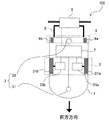
まず、本実施形態に係る自律走行台車100の全体構成について、図1を用いて説明する。図1は、自律走行台車の全体構成を示す図である。自律走行台車100は、台車部1と、走行部2と、検出部3と、操作部5と、制御部7と、を備える。台車部1は、自律走行台車100の本体を構成する。走行部2は、台車部1に搭載されている。走行部2は、走行制御指令(後述)に従って走行することにより、台車部1を走行させる。検出部3は、制御部7(後述)に信号送受信可能に接続されている。そして、検出部3は、障害物(人や他の台車などの走行障害物、荷物などの仮置き障害物)及び走行経路にある壁などを検出し、障害物及び壁などの位置情報を制御部7に出力する。操作部5は、台車部1の上部後方側に取付部材9を介して固定されている。また、操作部5は、制御部7に信号送受信可能に接続されている。操作部5は、操作者が自律走行台車100を操作することにより移動平面を手動走行させながら走行経路を教示するとき(手動操作教示モードの実行時)、操作者により操作される。これにより、自律走行台車100の走行モードが手動操作教示モードの実行時に、自律走行台車100は、操作者による操作部5の操作に基づいて制御される。また、操作部5は、自律走行台車100の各種設定を行う。
1. First Embodiment (1) Overall Configuration of Autonomous Traveling Dolly First, the overall configuration of an
制御部7は、走行部2のモータ23a、23b(後述)に電気的に接続されている。また、制御部7には、検出部3が信号送受信可能に接続されている。制御部7は、手動操作教示モードの実行時には、操作者による操作部5の操作に基づいて、操作走行制御指令を走行制御指令として作成し、走行部2のモータ23a、23bを制御する。
一方、走行経路を自律的に走行する再現走行モードの実行時には、制御部7は、手動操作教示モードの実行時において教示された走行経路を表す走行経路データ500(後述)に基づいて、再現走行制御指令(後述)を走行制御指令として作成し、走行部2のモータ23a、23bを制御する。
The
On the other hand, when the reproduction travel mode for autonomously traveling along the travel route is executed, the
また、制御部7は、再現走行モードの実行時において、所定の条件に基づいて自律走行経過時刻の進行を調整している。ここで、「時刻の進行」とは、時刻が進んでいく速度のことである。従って、自律走行経過時刻の進行は、必ずしも、実時間(実時刻)とは同一とはならない。そして、本実施形態の制御部7は、進行が調整された自律走行経過時刻と走行経路データ500に示された到達時刻(後述)とを比較して到達目標点を決定し、決定した到達目標点に基づいて、再現走行制御指令を作成している。
In addition, the
さらに、制御部7は、検出部3から得られる信号(後述)に基づいて、障害物及び壁などの位置情報を把握する。また、制御部7は、障害物及び壁などの位置情報に基づき、移動平面(走行環境)における自律走行台車100の位置を把握する。また、制御部7は、検出部3から得られる信号に基づいて、走行経路上、あるいは、走行経路に侵入してくる(と予測される)、走行の障害となる走行障害物および仮置き障害物を把握する。そして、再現走行モードの実行時において、走行障害物などの未知の障害物が検出された場合には、再現走行中の自律走行台車100の速度(再現走行速度)が調整される。
なお、自律走行台車100の走行部2、検出部3、操作部5、及び制御部7の構成の詳細については、後述する。
Furthermore, the
The details of the configuration of the traveling
自律走行台車100は、補助輪部8をさらに備える。補助輪部8は、2つの補助車輪8a、8bを有する。2つの補助車輪8aと8bは、それぞれが独立に回転可能なように台車部1の後方底部に取り付けられている。補助輪部8を備えることにより、自律走行台車100は安定に、かつ、スムーズに移動できる。
The
(2)走行部の構成
次に、走行部2の構成について図1を用いて詳細に説明する。走行部2は、2つの主輪21a、21bと、2つのモータ23a、23bと、を有する。主輪21a、21bは、台車部1の略中央部の底部に設置されている。
また、主輪21a、21bは、それぞれ、モータ23a、23bの出力回転軸に接続されている。これにより、主輪21aはモータ23aの回転に従って回転し、主輪21bはモータ23bの回転に従って回転する。すなわち、主輪21a及び主輪21bは、お互いに独立に回転可能となっている。そのため、主輪21aの回転速度と主輪21bの回転速度に差を持たせることにより、台車部1(自律走行台車100)の進行方向(向き)を変更できる。
(2) Configuration of Traveling Unit Next, the configuration of the traveling
The
モータ23a、23bは、制御部7に電気的に接続されている。モータ23a、23bはそれぞれ、制御部7のモータ駆動部75(図3)により、独立して制御可能となっている。従って、モータ23a、23bは、それぞれ独立に、任意の回転数で正逆に回転できる。その結果、主輪21a、21bは、それぞれ独立に、回転数の制御が可能である。
モータ23a、23bとしては、たとえば、サーボモータ及び/又はブラシレスモータなどの電動モータを用いることができる。
The
As the
(3)検出部の構成
次に、検出部3の構成について、図1を用いて説明する。検出部3は、自律走行台車100の走行経路周辺の障害物(走行障害物など)及び壁などを検出し、障害物及び壁などの位置情報を出力する。そのため、検出部3は、前方検出器31と、後方検出器33と、を有する。前方検出器31は、自律走行台車100の前方にある障害物及び壁などを検出する。後方検出器33は、自律走行台車100の後方にある障害物及び壁などを検出する。また、前方検出器31と後方検出器33は、自律走行台車100と障害物及び壁などとの間の距離及び、自律走行台車100から見た障害物及び壁などが存在する方向に関する情報などを含む信号を出力する。これにより、検出部3は、自律走行台車100から見た障害物及び壁などの相対的な位置情報を、制御部7に出力できる。
検出部3の前方検出器31及び後方検出器33としては、例えば、その検出範囲として180°以上で射程距離4m以上のレーザレンジファインダ(Laser Range Finder、LRF)などを用いることができる。
(3) Configuration of Detection Unit Next, the configuration of the
As the
前方検出器31及び後方検出器33の射程距離が4m以上であることにより、より離れた位置にある障害物を検知できる。これにより、自律走行台車100において、より早い段階において、自律走行台車100の速度を低減するか、又は、停止するかを判断できる。
なお、上記の射程距離は、4m以上に限られず、自律走行台車100の走行速度(最高速度)等により、適宜適切な射程距離を選択できる。
When the range of the
In addition, said range is not restricted to 4 m or more, According to the traveling speed (maximum speed) of the
(4)操作部の構成
次に、操作部5の構成について、図2を用いて説明する。図2は、操作部の構成を示す図である。操作部5は、操作ハンドル51a、51bと、設定部53と、表示部55と、インターフェース57と、筐体59と、を備える。
操作ハンドル51a、51bは、それぞれ、筐体59の左右に回動可能に取り付けられている。また、操作ハンドル51a、51bは、インターフェース57と信号送受信可能に接続されている。これにより、操作ハンドル51a、51bの回動量(操作量)及び回動方向は、インターフェース57において電気信号に変換され、制御部7に入力される。そして、制御部7に入力された操作ハンドル51a、51bの回動量及び回動方向に基づき、操作走行制御指令が作成され、作成された操作走行制御指令を走行制御指令として、走行部2のモータ23a、23bが制御される。
また、操作ハンドル51aを進行方向への走行速度を指示するための入力インターフェースとし、操作ハンドル51bを操舵角を指示するための入力インターフェースとしてもよい。
(4) Configuration of Operation Unit Next, the configuration of the
The operation handles 51 a and 51 b are attached to the left and right sides of the
The
これにより、操作者は、手動操作教示モードの実行時に操作ハンドル51a、51bを操作することにより、自律走行台車100に所望の走行経路を走行させることができる。
Thus, the operator can cause the
設定部53は、インターフェース57に接続されている。設定部53は、自律走行台車100の走行モードを、再現走行モード、又は、手動操作教示モードのいずれかに切り替える。そして、設定部53において設定された走行モードが、インターフェース57を介して、制御部7の切替部77(図3)に入力される。また、設定部53は、自律走行台車100のその他の各種設定を設定可能となっていてもよい。
設定部53は、例えば、自律走行台車100の走行モード及び各種設定などを行うためのスイッチ又は/及びキーボードなどにより構成できる。又は、設定部53は、タッチパネルとして構成され、表示部55と一体に形成されていてもよい。
The setting
The setting
表示部55は、インターフェース57に接続されている。表示部55は、インターフェース57を介して、制御部7から自律走行台車100の各種設定などの情報を、読み出して表示する。表示部55としては、液晶ディスプレイなどのディスプレイを用いることができる。また、上記のように、設定部53と表示部55とを一体に形成する場合は、表示部55(と設定部53)として、タッチパネル機能付きディスプレイを用いることができる。
The
インターフェース57は、制御部7に接続されている。インターフェース57は、操作ハンドル51a、51bの回動量、回動方向、及び設定部53のスイッチ及び/又はキー入力などを電気信号に変換し、制御部7へ出力する。また、インターフェース57は、操作者の指示などに応じて、制御部7から自律走行台車100に関する情報を読み出して、表示部55に表示する。
従って、インターフェース57としては、マイコンボードを用いることができる。マイコンボードは、例えば、操作ハンドル51a、51bの回動量、回転方向、及び設定部53における設定状態を電気信号に変換する信号変換器と、表示部55に情報を表示するための表示部駆動回路と、制御部7と信号を送受信するための通信インターフェースと、を備えている。
The
Therefore, a microcomputer board can be used as the
(5)制御部の構成
I.制御部の全体構成
次に、制御部7の全体構成について図3を用いて説明する。図3は、制御部の全体構成を示す図である。
なお、制御部7は、CPU(Central Processing Unit)と、ハードディスク装置と、ROM(Read Only Memory)と、RAM(Random Access Memory)と、記憶媒体読み出し装置などにより構成される記憶装置と、信号変換を行うインターフェースなどと、を備えたマイコンシステムなどのコンピュータにより実現できる。
(5) Configuration of control unit Overall Configuration of Control Unit Next, the overall configuration of the
The
また、以下に示す制御部7の各部の機能の一部又は全部は、上記マイコンシステムなどのコンピュータにおいて実行可能なプログラムとして実現されていてもよい。さらに、当該プログラムは、マイコンボードの記憶装置に記憶されていてもよい。又は、制御部7の各部の機能の一部又は全部は、カスタムICなどにより実現されていてもよい。
In addition, some or all of the functions of the respective units of the
制御部7は、教示データ作製部71と、位置推定部72と、記憶部73と、経過時刻計数部74と、モータ駆動部75と、障害物情報取得部76と、切替部77と、を有する。
The
教示データ作製部71は、手動操作教示モードの実行時に、操作者が操作部5を用いて自律走行台車100を操作することにより通過した位置に関する情報を所定の時刻毎に取得する。そして、教示データ作製部71は、当該位置に関する情報を、自律走行台車100が走行する移動平面を表現した座標系(以後、移動座標と呼ぶことにする)上の座標値に変換する。さらに、教示データ作製部71は、座標変換された位置に関する情報と、当該位置に関する情報を取得したときの教示経過時間とを関連づけて記憶部73(後述)に記憶する。
ここで、上記の位置に関する情報は、走行予定の走行経路上に設定された通過すべき目標点である。従って、上記の位置に関する情報のことを、「教示サブゴール点」又は「サブゴール点」と呼ぶことにする。
The teaching
Here, the information on the position is a target point to be passed set on a travel route scheduled to travel. Therefore, the information on the position is referred to as “teach subgoal point” or “subgoal point”.
また、教示データ作製部71は、手動操作教示モードの実行時に、自律走行台車100の走行開始位置から、操作者が自律走行台車100の走行を終了させる(手動操作教示モードの終了、あるいは、走行終了位置に到達する)まで、教示サブゴール点の取得を継続する。この結果、教示データ作製部71は、走行開始位置から走行終了位置までに取得した複数の教示サブゴール点の集合体と、複数の教示サブゴール点のそれぞれに関連づけられた教示経過時刻の集合体とを、記憶部73に記憶できる。
In addition, when the manual operation teaching mode is executed, the teaching
このように、手動操作教示モードの実行時に、操作者の操作により自律走行台車100が通過した位置を座標値(教示サブゴール点)の集合体として取得し記憶することにより、操作者の操作により教示された自律走行台車100の走行経路を記憶部73に記憶できる。従って、教示データ作製部71が取得した教示サブゴール点の集合体と、複数の教示サブゴール点のそれぞれに関連づけられている教示経過時刻の集合体とを記憶したデータのことを、「走行経路データ」と呼ぶことにする。また、複数の教示サブゴール点のそれぞれに関連づけられている教示経過時刻のことを「到達時刻」と呼ぶ。さらに、走行経路データ500に記憶されている教示サブゴール点のことを単に「サブゴール点」と呼ぶこともある。
As described above, when the manual operation teaching mode is executed, the position through which the
また、走行経路データ500に、手動操作教示モードの実行時に自律走行台車100が通過した位置に関する情報(教示サブゴール点、又は、サブゴール点)と、教示サブゴール点を取得した教示経過時刻(到達時刻)とが関連づけられて記憶されることにより、走行経路データ500に位置に関する情報だけでなく、時刻に関する情報も記憶できる。
その結果、再現走行モードの実行時に、教示された走行経路を再現走行する際、再現走行指令算出部753(図5)は、自律走行経過時刻(後述)と走行経路データ500中の到達時刻とを比較しつつ、走行経路データ500中のどの教示サブゴール点(サブゴール点)を、次の走行目標のサブゴール点とするべきかを適切に選択できる。
Further, in the
As a result, at the time of executing the reproduction travel mode, the reproduction travel command calculation unit 753 (FIG. 5) performs the autonomous travel elapsed time (described later), the arrival time in the
また、教示データ作製部71は、教示サブゴール点を取得するときに、当該教示サブゴール点における自律走行台車100の速度(教示速度)を取得し、教示速度と教示サブゴール点とを関連づけて、記憶部73に記憶する。この場合、走行経路データ500は、教示サブゴール点(サブゴール点)の集合体と、到達時刻の集合体と、教示速度の集合体とにより構成される。
Further, when acquiring the teaching subgoal point, the teaching
このように、走行経路データ500に(教示)サブゴール点における(教示)速度をサブゴール点に関連づけて記憶することにより、手動操作教示モードの実行時において、走行経路を教示する際の実際の自律走行台車100の速度を、走行経路データ500として記憶できる。また、再現走行モードの実行中に、各サブゴール点を通過する際の速度を走行経路データ500から参照できる。
In this way, by storing the (teaching) speed at the (teaching) subgoal point in association with the subgoal point in the traveling
また、走行経路データ500に(教示)サブゴール点における(教示)速度をサブゴール点に関連づけて記憶することにより、例えば、一定時間停止するといった時間の概念を含む走行を走行経路データ500に記憶できる。そして、再現走行モードの実行時に、自律走行台車100がこのような走行経路データ500を忠実に再現することにより、走行経路データ500に示された走行経路を忠実に再現しつつ、時間の概念を有する走行を忠実に再現できる。
Further, by storing the (teaching) speed at the (teaching) subgoal point in association with the subgoal point in the traveling
なお、上記の教示サブゴール点における自律走行台車100の速度である教示速度は、例えば、操作部5の回動量及び/又は回動方向から算出される操作走行制御指令(後述)に基づいて算出される。その他、単位時間当たりのモータ23a、23b又は主輪21a、21bの回転量からも教示速度を算出できる。さらに、位置推定部72(後述)において推定された自律走行台車100の位置の単位時間当たりの変化から教示速度を算出してもよい。
The teaching speed that is the speed of the
位置推定部72は、走行環境(移動平面上)における台車部1(自律走行台車100)の位置を所定の時間毎に推定する。位置推定部72は、例えば、SLAM(Simultaneous Localization And Mapping)法などを用いて、自律走行台車100の移動平面上における位置を推定できる。
The
位置推定部72は、検出部3において取得された自律走行台車100から見た障害物及び/又は壁などの相対的な位置情報を、移動座標上の座標値へと変換する。そして、位置推定部72は、検出部3の前方検出器31及び後方検出器33が検出した障害物及び/又は壁などの位置情報に基づいて、自律走行台車100の周囲の移動平面の地図情報(ローカルマップと呼ぶことにする)を作成する。また、位置推定部72は、移動平面の地図情報(環境地図と呼ぶことにする)を記憶部73に記憶している。そして、位置推定部72は、環境地図とローカルマップとを比較して、自律走行台車100が移動平面のどの位置に存在するかを推定する。
The
また、位置推定部72は、モータ23a、23bの回転数に基づいても、自律走行台車100の位置を推定できるようになっている(デッドレコニング)。そのため、モータ23a、23bの出力回転軸には、それぞれ、軸の回転数を測定する装置が取り付けられている。本実施形態においては、モータ23a、23bの出力回転軸には、それぞれ、エンコーダ231a、231b(図5)が取り付けられている。このように、検出部3による位置推定と、モータ23a、23bの回転数に基づいた位置推定とを組み合わせることにより、互いの位置推定結果を相互補完できる。その結果、検出部3のみ、又は、モータ23a、23bの回転数のみに基づく位置推定よりも、さらに精度のよい位置の推定ができる。
Moreover, the
記憶部73は、制御部7がマイコンシステムにより実現されている場合は、マイコンシステムなどのコンピュータの記憶装置(あるいは、記憶装置の記憶領域の一部)に対応するものである。記憶部73は、自律走行台車100の各種設定、走行経路データ500、障害物(走行障害物など)及び壁などの位置情報、などの情報を記憶する。また、制御部7の各部の機能の一部又は全部が上記コンピュータにより実行可能なプログラムにより実現されているとき、記憶部73は、当該プログラムを記憶してもよい。
When the
経過時刻計数部74は、自律走行台車100において用いる各種経過時刻を計数する。本実施形態において、経過時刻としては、自律走行経過時刻(後述)と教示経過時刻とが存在する。自律走行経過時刻は、自律走行台車100において再現走行モードが実行中に計数される時刻であり、再現走行モード開始時(再現走行モードの実行が開始された時点)からの経過時刻である。一方、教示経過時刻は、自律走行台車100において手動操作教示モードが実行中に計数される時刻であり、手動操作教示モード開始時(手動操作教示モードの実行が開始された時点)からの経過時刻である。
なお、経過時刻計数部74の詳細な構成及び動作については、後述する。
The elapsed
The detailed configuration and operation of the elapsed
モータ駆動部75は、モータ23a、23bに接続されている。これにより、モータ駆動部75は、モータ23a、23bを制御できる。
モータ駆動部75は、操作部5と信号送受信可能に接続され、手動操作教示モードの実行時には、操作部5の操作ハンドル51a、51bの回動量及び/又は回動方向に基づき、操作走行制御指令を作成する。そして、モータ駆動部75は、操作走行制御指令を走行制御指令として、モータ23a、23bを制御する。
The
The
一方、再現走行モードの実行時には、モータ駆動部75は、記憶部73に記憶された走行経路データ500に基づいて、再現走行制御指令を作成する。そして、モータ駆動部75は、再現走行制御指令を走行制御指令として、モータ23a、23bを制御する。
なお、モータ駆動部75の詳細な構成及び動作については、後述する。
On the other hand, when the reproduction travel mode is executed, the
The detailed configuration and operation of the
障害物情報取得部76は、検出部3の前方検出器31と後方検出器33とに信号送受信可能に接続されている。障害物情報取得部76は、前方検出器31と後方検出器33とから出力される信号に基づき、障害物及び壁などの位置情報を取得する。そして、障害物情報取得部76は、必要に応じて、障害物及び壁などの位置情報を記憶部73に記憶する。このとき、障害物情報取得部76は、位置推定部72に障害物及び壁などの位置情報を出力してもよい。そして、位置推定部72が、障害物及び壁などの位置情報を移動座標上の座標値に変換して、障害物及び壁などの位置情報を記憶部73に記憶してもよい。
The obstacle
また、障害物情報取得部76は、再現走行速度調整部759(図5)と信号送受信可能となっている。そのため、障害物情報取得部76は、再現走行モードの実行時に、自律走行の障害となる走行障害物の位置に関する情報を、再現走行速度調整部759へと送信できる。
The obstacle
切替部77は、操作部5の設定部53における走行モードの設定状態に基づいて、自律走行台車100の走行モードを、再現走行モード、又は、手動操作教示モードのいずれかに切り替えて設定する。そして、制御部7の各部は、必要に応じて、切替部77において設定された走行モードを参照可能となっている。
The switching
II.経過時刻計数部の構成
次に、経過時刻計数部74の構成について図4を用いて説明する。図4は、経過時刻計数部の構成を示す図である。経過時刻計数部74は、自律走行経過時刻計数部741と、教示経過時刻計数部743と、を有する。
自律走行経過時刻計数部741は、再現走行モードの実行時に、自律走行経過時刻を計数する。自律走行経過時刻計数部741は、自律走行経過時間の進行を所定の条件に基づいて調整しながら自律走行経過時刻を計数する。
II. Configuration of Elapsed Time Counting Unit Next, the configuration of the elapsed
The autonomous traveling elapsed
具体的には、再現走行モードの実行中に、自律走行台車100の速度(再現走行速度)が走行経路データ500に示された教示速度よりも小さくなった場合には、自律走行経過時刻計数部741は、自律走行経過時間の進行を実時間よりも遅らせる。
一方、再現走行モードの実行中に自律走行台車100が、走行経路データ500に示されていない停止を実行した場合には、自律走行経過時刻計数部741は、自律走行経過時刻の計数を停止する。
Specifically, when the speed of the autonomous traveling vehicle 100 (reproduced traveling speed) becomes lower than the teaching speed indicated in the traveling
On the other hand, when the
このように、自律走行経過時刻計数部741が、再現走行モードの実行時に、所定の条件(例えば、走行経路データ500には示されていない予定外の減速や停止など)に基づいて自律走行経過時刻の進行を調整することにより、再現走行指令算出部753は、自律走行経過時刻と走行経路データ500中の到達時刻とを比較して、適切なサブゴール点を次の到達目標点として選択できる。その結果、自律走行台車100は、忠実に走行経路データ500に示された走行経路を再現走行できる。
As described above, the autonomous traveling elapsed
後述するように、自律走行経過時刻計数部741は、単位経過時間を後述の制御タイミング毎に累積加算することにより自律走行経過時刻を計数する。単位経過時間とは、自律走行経過時刻の進行速度を決定するものである。本実施形態においては、単位経過時間は、調整された再現走行速度に基づいて調整される。
As will be described later, the autonomous running elapsed
教示経過時刻計数部743は、手動操作教示モードの実行時に、教示経過時刻を計数する。教示経過時刻計数部743は、例えば、手動操作教示モードの開始時から所定の単位時間を累積加算することにより、教示経過時刻を計数する。所定の単位時間としては、例えば、モータ駆動部75におけるモータ23a、23bの制御周期を用いることができる。その他、制御部7を構成するコンピュータシステムのクロック周期、又は、コンピュータシステムにて用いられている時刻を、上記の単位時間として用いることもできる。
The teaching elapsed
III.モータ駆動部の構成
次に、モータ駆動部75の構成について、図5を用いて説明する。図5は、モータ駆動部の構成を示す図である。
モータ駆動部75は、駆動切替部751と、再現走行指令算出部753と、モータ制御部755と、操作走行制御指令算出部757と、再現走行速度調整部759と、を有する。
III. Configuration of Motor Drive Unit Next, the configuration of the
The
駆動切替部751は、切替部77と信号送受信可能に接続されている。また、駆動切替部751は、3つの端子d、e、fを有している。駆動切替部751は、切替部77において手動操作教示モードが選択された場合、端子dと端子eとを接続する。また、駆動切替部751は、切替部77において再現走行モードが選択された場合、端子eと端子fとを接続する。
その結果、駆動切替部751は、手動操作教示モードの実行時には、操作走行制御指令をモータ制御部755(後述)へと入力する。一方、駆動切替部751は、再現走行モードの実行時には、再現走行指令算出部753(後述)において算出された再現走行制御指令(後述)をモータ制御部755へと入力する。
The
As a result, the
再現走行指令算出部753は、記憶部73と信号送受信可能に接続されている。そのため、再現走行指令算出部753は、記憶部73に記憶されている走行経路データ500を参照できる。また、再現走行指令算出部753は、自律走行経過時刻計数部741と信号送受信可能に接続されている。そのため、再現走行指令算出部753は、自律走行経過時刻を参照できる。さらに、再現走行指令算出部753は、駆動切替部751の端子fと接続されている。
The reproduction travel
従って、再現走行指令算出部753は、再現走行モードの実行時に、自律走行経過時刻と、走行経路データ500中の到達時刻とを比較し、自律走行経過時刻の直後の到達時刻を目標到達時刻とする。その後、再現走行指令算出部753は、走行経路データ500から目標到達時刻に関連づけられているサブゴール点(到達目標点)を読み出して、読み出したサブゴール点に基づいて再現走行制御指令を算出する。
Therefore, the reproduction travel
そして、再現走行モードの実行時には、駆動切替部751の端子fと端子eとが接続されているため、算出された再現走行制御指令がモータ制御部755へと出力される。これにより、再現走行モードの実行時には、再現走行指令算出部753において算出された再現走行制御指令に基づいて、モータ23a、23bが制御される。
When the reproduction travel mode is executed, since the terminal f and the terminal e of the
モータ制御部755は、モータ23a、23bと電気的に接続されている。また、モータ制御部755は、モータ23a、23bのそれぞれに備えられたエンコーダ231a、231bと信号送受信可能に接続されている。さらに、モータ制御部755は、駆動切替部751の端子eと接続されている。
The
従って、モータ制御部755は、手動操作教示モードの実行時には、駆動切替部751を介して、操作走行制御指令(後述)を入力する。一方、再現走行モードの実行時には、モータ制御部755は、駆動切替部751を介して、再現走行制御指令を入力する。
このため、モータ制御部755は、手動操作教示モードの実行時には、操作走行制御指令に基づいて、モータ23a、23bを制御する。一方、再現走行モードの実行時には、モータ制御部755は、再現走行制御指令に基づいて、モータ23a、23bを制御する。
Therefore, the
Therefore, the
また、モータ制御部755は、モータ23a、23bを制御する際に、エンコーダ231a、231bにより測定されたモータ23a、23bの回転数及び回転量などをモニターしている。そして、モータ制御部755は、モータ23a、23bの回転数及び回転量などをフィードバックして、モータ23a、23bを制御している(フィードバック制御)。
そのため、モータ制御部755としては、フィードバック制御理論を用いたモータ制御装置などを用いることができる。
Further, the
Therefore, as the
操作走行制御指令算出部757は、操作部5と信号送受信可能に接続されている。そのため、操作走行制御指令算出部757は、操作部5の操作ハンドル51a、51bの回動量及び/又は回動方向を入力する。そして、当該回動量及び/又は回動方向に基づいて、操作走行制御指令を算出する。
また、操作走行制御指令算出部757は、駆動切替部751の端子dと接続されている。そのため、操作走行制御指令算出部757は、手動操作教示モードの実行時(すなわち、端子dと端子eとが接続されたとき)、駆動切替部751を介して、操作走行制御指令をモータ制御部755に出力する。
The operation travel control
In addition, the operation travel control
さらに、操作走行制御指令算出部757は、教示データ作製部71と信号送受信可能に接続されている。そのため、操作走行制御指令算出部757は、手動操作教示モードの実行時に、操作走行制御指令を教示データ作製部71に出力できる。
本実施形態においては、操作走行制御指令は、操作ハンドル51a、51bの回動量及び/又は回動方向を数値化したものである。例えば、操作走行制御指令は、操作ハンドル51a、51bの回動量の最大の回動量に対する割合の数値に、操作ハンドル51a、51bの回動方向に従って決定される正負の符号を付した数値とすることができる。
この場合、モータ制御部755は、操作走行制御指令に示された数値と、モータ制御部755において予め決められているモータ23a、23bの最大回転速度との積により、モータ23a、23bの回転速度を決定できる。
Furthermore, the operation travel control
In the present embodiment, the operation travel control command is a numerical value of the rotation amount and / or rotation direction of the operation handles 51a and 51b. For example, the operation travel control command is a numerical value obtained by adding a positive / negative sign determined according to the rotation direction of the operation handles 51a and 51b to the numerical value of the ratio of the rotation amount of the operation handles 51a and 51b to the maximum rotation amount. Can do.
In this case, the
再現走行速度調整部759は、障害物情報取得部76と信号送受信可能に接続されている。このため、再現走行速度調整部759は、再現走行モードの実行時に、走行経路上の走行の障害となる走行障害物、及び/又は、走行経路周辺に存在し走行経路に進入する可能性のある走行障害物の位置に関する情報(走行障害物位置情報)を、取得できる。これにより、再現走行速度調整部759は、走行障害物の位置(走行障害物位置情報)に基づいて、再現走行モードの実行時における自律走行台車100の速度(再現走行速度)を調整できる。
The reproduction travel
また、再現走行速度調整部759は、モータ制御部755と信号送受信可能に接続されている。このため、再現走行速度調整部759は、調整した再現走行速度を出力できる。この場合、再現走行速度調整部759は、例えば、再現走行速度を低下させたい場合には、再現走行速度をどの程度低下したいかを示す調整係数を出力できる。
一方、再現走行速度調整部759は、再現走行モードの実行時に自律走行台車100を停止させたい場合は、例えば、再現走行速度、又は、上記の調整係数を0とする信号をモータ制御部755に出力できる。
The reproduction travel
On the other hand, when the reproduction travel
さらに、再現走行速度調整部759は、自律走行経過時刻計数部741と信号送受信可能に接続されている。このため、再現走行速度調整部759は、再現走行速度をどの程度低下したいかを示す上記調整係数、又は、自律走行経過時刻の計数を停止する指令を自律走行経過時刻計数部741に送信できる。
これにより、自律走行経過時刻計数部741は、再現走行速度が低下したときには、上記の調整係数を用いて、自律走行経過時刻に対して累積加算する単位経過時間の長さを調整できる。また、自律走行経過時刻計数部741は、自律走行台車100が停止したときには、自律走行経過時刻の計数を停止する指令を受信することにより、自律走行経過時刻計数部741の計数を停止できる。
Furthermore, the reproduction travel
Thereby, the autonomous running elapsed
(6)自律走行台車の動作
I.自律走行台車の基本動作
次に、本実施形態に係る自律走行台車100の基本動作について、図6Aを用いて説明する。図6Aは、自律走行台車の基本動作を示すフローチャートである。ここでは、操作者が操作部5を操作して自律走行台車100を走行させて自律走行台車100に走行経路を教示させた上で、教示された走行経路を再現走行モードの実行時に再現走行する例を示す。
走行経路データ500の作成を開始すると、教示データ作製部71が、自律走行台車100を操作者が操作することにより自律走行台車100が通過した走行経路の走行経路データ500を取得し、記憶部73に記憶する(ステップS1)。
(6) Operation of autonomous traveling cart Next, the basic operation of the
When the creation of the
本実施形態においては、走行経路データ500には、自律走行台車100が通過した走行経路上の位置を示す教示サブゴール点のみでなく、各教示サブゴール点が取得されたときの教示経過時刻(到達時刻)と、各教示サブゴール点における自律走行台車100の速度(教示速度)とが、教示サブゴール点(サブゴール点)に関連づけられて記憶されている。ここで、到達時刻は教示を開始した時刻から停止することなく教示終了まで計時する。
これにより、再現走行指令算出部753は、再現走行モードの実行時に、自律走行経過時刻と走行経路データ500中の到達時刻とを比較しつつ、どのサブゴール点を次の到達目標点とするかを適切に決定できる。その結果、自律走行台車100は、再現走行モードの実行時に、走行経路データ500に示された走行経路を忠実に再現走行できる。
なお、ステップS1における走行経路データ500の取得方法については、後ほど詳しく説明する。
In the present embodiment, the
Thereby, the reproduction travel
In addition, the acquisition method of the
走行経路データ500を取得後、自律走行台車100を自律走行させたい場合は、設定部53などにより自律走行台車100の走行モードを再現走行モードに切り替える。そして、自律走行台車100が、走行経路データ500に示された走行経路を自律的に再現走行する(ステップS2)。
自律走行台車100は、走行経路データ500に示された走行経路を自律的に再現走行するとき、検出部3により、走行経路上あるいは走行経路に侵入すると考えられる走行の障害となる走行障害物などの位置に関する情報を取得している。そして、自律走行台車100は、走行障害物の位置に関する情報に基づいて、再現走行中の速度(再現走行速度)を調整する。
When the
When the
例えば、走行障害物などと自律走行台車100との距離が十分に大きい場合、自律走行台車100の再現走行速度調整部759は、走行障害物が走行経路から抜け出ることを待つなどのために、再現走行速度を走行経路データ500に示された教示速度よりも低下させる。一方、走行障害物と自律走行台車100との距離が小さい場合、再現走行速度調整部759は、走行障害物と自律走行台車100との衝突を避けるため、再現走行速度を0とする。
For example, when the distance between the traveling obstacle or the like and the
そして、再現走行モードの実行時においては、本実施形態の自律走行経過時刻計数部741は、調整された再現走行速度に基づいて、自律走行経過時刻の進行速度を調整する。例えば、上記のように、走行障害物が検出されて、再現走行速度が教示速度よりも減少した場合には、自律走行経過時刻の進行を遅らせる。
一方、再現走行速度が0(すなわち、自律走行台車100が停止)となった場合には、自律走行経過時刻の計数(進行)を停止する。
Then, when the reproduction travel mode is executed, the autonomous travel elapsed
On the other hand, when the reproduced traveling speed becomes 0 (that is, the
このように、再現走行モードの実行時に、自律走行台車100において、走行経路データ500に示されていない予想外の再現走行速度の変化(調整)が生じた場合に、自律走行経過時刻の進行速度を再現走行速度に従って調整することにより、再現走行指令算出部753は、自律走行経過時刻と到達時刻とを比較しつつ、どのサブゴール点を次の到達目標点とするかを適切に決定できる。その結果、自律走行台車100は、再現走行モードの実行時に、走行経路データ500に示された走行経路を忠実に再現走行できる。
なお、ステップS2における自律走行台車100の再現走行方法については、後ほど詳しく説明する。
As described above, when an unexpected travel speed change (adjustment) not shown in the
The method for reproducing the
II.走行経路データの取得方法
まず、図6AのステップS1における、走行経路データ500の取得方法について、図6Bを用いて説明する。図6Bは、走行経路データの取得方法を示すフローチャートである。ここで示す例においては、上記のように、操作者が操作部5を操作して自律走行台車100を走行させて自律走行台車100に走行経路を教示させる方法にて走行経路データ500が取得される。
従って、まず、自律走行台車100の走行モードが手動操作教示モードに設定される(ステップS11)。走行モードの手動操作教示モードへの切替は、例えば、操作者が操作部5の設定部53を操作することにより、実行される。
II. Method for Obtaining Travel Route Data First, a method for obtaining the
Therefore, first, the traveling mode of the
設定部53により走行モードが手動操作教示モードへ切り替えられると、走行モードが手動操作教示モードとなったことが制御部7の切替部77に通知される。そして、切替部77は、モータ駆動部75の駆動切替部751に対して、駆動切替部751の端子dと端子eとを接続するよう指令する。これにより、操作部5の操作ハンドル51a、51bの回動量及び回動方向に基づいて算出された操作走行制御指令が、モータ制御部755に入力される。
これにより、操作者は、操作ハンドル51a、51bの回動量及び回動方向などを調整することにより、自律走行台車100を手動操作できる。
When the travel mode is switched to the manual operation teaching mode by the setting
Thereby, the operator can manually operate the
また、走行モードを手動操作教示モードに設定したタイミングにおいて、教示経過時刻計数部743が、教示経過時刻の計数を開始する。本実施形態においては、教示経過時刻計数部743は、モータ23a、23bの制御周期を上記の単位時間として、手動操作教示モードの開始時から累積加算して、教示経過時刻を計数する。
In addition, at the timing when the traveling mode is set to the manual operation teaching mode, the teaching elapsed
走行モードを手動操作教示モードに設定後、操作者が自律走行台車100を手動により操作する。操作者による手動操作中に、教示データ作製部71は、所定の時間毎に、操作者の操作により自律走行台車100が通過した移動平面上の位置を、教示サブゴール点として取得する(ステップS12)。または、操作者による手動操作中に、教示データ作製部71は、所定の距離を走行する毎に、移動平面上の位置とそのときの到達時刻とを、教示サブゴール点として取得しても良い。
After setting the traveling mode to the manual operation teaching mode, the operator manually operates the
このとき、教示サブゴール点を取得する所定の時間は、制御タイミングが発生する周期の倍数であることが好ましい。これにより、上記の教示された教示経過時刻と再現走行時の自律走行経過時刻とのずれを0とできる。 At this time, it is preferable that the predetermined time for acquiring the teaching subgoal point is a multiple of a cycle in which the control timing occurs. Thereby, the deviation between the taught teaching elapsed time and the autonomous traveling elapsed time during the reproduction traveling can be made zero.
サブゴール点を取得する際、教示データ作製部71は、位置推定部72に対して、現在の自律走行台車100の移動座標上の位置(サブゴール点の座標)を推定するよう指令する。そして、位置推定部72は、当該指令に対して、座標値により表現された位置(サブゴール点)を、教示サブゴール点として教示データ作製部71に出力する。
When acquiring the subgoal point, the teaching
教示サブゴール点を取得後、教示データ作製部71は、教示サブゴール点を取得したときの教示経過時刻を、教示経過時刻計数部743から取得する(ステップS13)。
After acquiring the teaching subgoal point, the teaching
さらに、教示データ作製部71は、取得したサブゴール点を通過している際の自律走行台車100の速度を、教示速度として取得する(ステップS14)。
このとき、教示データ作製部71は、操作走行制御指令算出部757において算出された、操作者の操作による操作部5の回動量及び回動方向から算出される操作走行制御指令を、操作走行制御指令算出部757から受信する。そして、教示データ作製部71は、受信した操作走行制御指令を、教示速度として取得する。
Further, the teaching
At this time, the teaching
その他、教示データ作製部71は、単位時間当たりのモータ23a、23b又は主輪21a、21bの回転量から教示速度を算出してもよい。さらに、教示データ作製部71は、位置推定部72において推定された自律走行台車100の位置の単位時間当たりの変化から教示速度を算出してもよい。適宜、適切な方法により、教示データ作製部71は、教示速度を取得できる。
これにより、再現走行指令算出部753は、後述するように、走行経路データ500に示された各サブゴール点に関連づけられた教示速度に基づいて、再現走行制御指令を算出できる。
In addition, the teaching
Thereby, the reproduction travel
上記のステップS12〜S14を実行して、教示サブゴール点と、教示サブゴール点を取得したときの教示経過時刻と、教示サブゴール点を取得したときの教示速度とを取得後、教示データ作製部71は、教示サブゴール点と、教示経過時刻と、教示速度と、を関連づけて、図7Aに示すような走行経路データ単位500−kを生成する(ステップS15)。図7Aは、走行経路データ単位の一例を示す図である。
After executing the above steps S12 to S14 to obtain the teaching subgoal point, the teaching elapsed time when the teaching subgoal point is acquired, and the teaching speed when the teaching subgoal point is acquired, the teaching
図7Aに示す走行経路データ単位500−kは、k番目に取得された教示サブゴール点に対して生成された走行経路データ単位である。図7Aに示すように、走行経路データ単位500−kは、到達時刻記憶領域501−kと、サブゴール点記憶領域503−kと、教示速度記憶領域505−kと、を有する。この走行経路データ単位500−kにおいては、到達時刻記憶領域501−kと、サブゴール点記憶領域503−kと、教示速度記憶領域505−kとが、紙面の横方向に接続されている。 A travel route data unit 500-k shown in FIG. 7A is a travel route data unit generated for the kth acquired teaching subgoal point. As shown in FIG. 7A, the travel route data unit 500-k has an arrival time storage area 501-k, a subgoal point storage area 503-k, and a teaching speed storage area 505-k. In this travel route data unit 500-k, an arrival time storage area 501-k, a subgoal point storage area 503-k, and a teaching speed storage area 505-k are connected in the horizontal direction of the drawing.
走行経路データ単位500−kの到達時刻記憶領域501−kには、k番目の教示サブゴール点を取得したときの教示経過時刻が、到達時刻(Tk)として記憶される。サブゴール点記憶領域503−kには、k番目に取得した教示サブゴール点の座標値(xk,yk)が記憶される。そして、教示速度記憶領域505−kには、k番目の教示サブゴール点(xk,yk)における教示速度(vk)が記憶されている。 In the arrival time storage area 501-k of the travel route data unit 500-k, the teaching elapsed time when the k-th teaching subgoal point is acquired is stored as the arrival time (T k ). Coordinate values (x k , y k ) of the kth acquired teaching subgoal point are stored in the subgoal point storage area 503-k. The teaching speed storage area 505-k stores the teaching speed (v k ) at the k-th teaching subgoal point (x k , y k ).
図7Aに示すような構造を有する走行経路データ単位500−kに、教示サブゴール点と、教示経過時刻(到達時刻)と、教示速度とを記憶することにより、到達時刻と教示速度とを、教示サブゴール点に関連づけて記憶できる。 By storing the teaching subgoal point, the teaching elapsed time (arrival time), and the teaching speed in the travel route data unit 500-k having the structure as shown in FIG. 7A, the reaching time and the teaching speed are taught. Can be stored in association with subgoal points.
走行経路データ単位500−kを生成後、教示データ作製部71は、走行経路データ単位500−kを記憶部73に記憶する(ステップS16)。
サブゴール点を記憶部73に記憶する際、すでにいくつかの走行経路データ単位が記憶部73に記憶され走行経路データ500(図7B)が形成されている場合には、今回作製した走行経路データ単位500−kは、記憶されている走行経路データ500の末尾に追加される。
After generating the travel route data unit 500-k, the teaching
When the subgoal points are stored in the
走行経路データ単位500−kを記憶部73に記憶後、教示データ作製部71は、次の教示サブゴール点の取得までの間に、操作者の手動操作による走行経路の教示が終了したかどうかを確認する(ステップS17)。ここで、走行経路の教示が終了したかどうかの判断は、例えば、走行経路の教示が終了したことを教示データ作製部71に通知するスイッチやアイコン(図示せず)を操作部5に設けて、操作者が当該スイッチやアイコンを操作することにより、走行経路の教示が終了したことを通知してもよい。
After storing the travel route data unit 500-k in the
または、操作ハンドル51a、51bの回動量が0(操作されていない)であることを予め設定した一定時間検知したときに、走行経路の教示が終了したと、教示データ作製部71が判断してもよい。その他、操作者が自律走行台車100の操作を終了したことを検出する他の手段により、走行経路の教示が終了したかどうかを判断できる。
Alternatively, when it is detected that the rotation amount of the operation handles 51a and 51b is 0 (not operated) for a predetermined time, the teaching
操作者の手動操作による走行経路の教示が終了したと判断した場合(ステップS17において、「Yes」の場合)、教示データ作製部71は、走行経路データ500の取得を終了する。
一方、操作者の手動操作による走行経路の教示が継続していると判断した場合(ステップS17において、「No」の場合)、ステップS12に戻り、上記の走行経路データ単位500−kの生成と記憶とを継続する。これにより、教示データ作製部71は、走行経路の教示が継続している限り(すなわち、手動操作教示モードが実行されている限り)、走行経路データ単位500−kの生成と記憶とを継続できる。
When it is determined that the teaching of the travel route by the manual operation by the operator has ended (in the case of “Yes” in step S <b> 17), the teaching
On the other hand, when it is determined that the teaching of the travel route by the manual operation of the operator is continued (in the case of “No” in step S17), the process returns to step S12 to generate the travel route data unit 500-k. Continue to remember. Thus, the teaching
例えば、教示サブゴール点をn+1個取得するまで上記の走行経路データ単位500−kの生成と記憶とが継続されたときには、図7Bに示すような走行経路データ500が取得される。図7Bは、走行経路データの一例を示す図である。
図7Bに示す走行経路データ500においては、n+1個の走行経路データ単位500−0、500−1、500−2、500−3、・・・、500−n−1、500−nが、紙面の上から下へ積み重なるように接続されている。すなわち、図7Bに示す走行経路データ500は、n+1個の走行経路データ単位により構成されている。
For example, when the generation and storage of the travel route data unit 500-k is continued until n + 1 teaching subgoal points are obtained,
In the
このように、上記のステップS11〜S17を実行することにより、教示データ作製部71は、図7Bに示すような、各教示サブゴール点と、各教示サブゴール点を取得した到達時刻と、各教示サブゴール点における教示速度とが関連づけられて記憶された走行経路データ500を作製できる。
In this way, by executing the above steps S11 to S17, the teaching
III.再現走行方法
(i)再現走行の原理
次に、本実施形態の自律走行台車100における、走行経路データ500に示された再現走行の原理について説明する。ここでは、図8に示すような、走行経路データ500のk番目からk+3番目までの再現走行を例にとって説明する。図8は、走行経路データ500に示されたサブゴール点、及び、サブゴール点に関連づけられている速度及び到達時刻の関係を模式的に示した図である。
図8に示すように、走行経路データ500のk番目からk+3番目までのサブゴール点Pk、Pk+1、Pk+2、Pk+3のそれぞれをについて、到達時刻Tk、Tk+1、Tk+2、Tk+3と、教示速度vk、vk+1、vk+2、vk+3が関連づけられているとする。その結果、図8における位置と到達時刻の関係を示すグラフにおいて実線にて示された折れ線のような走行経路が教示されているとする。
III. Reproduction Travel Method (i) Principle of Reproduction Travel Next, the principle of reproduction travel shown in the
As shown in FIG. 8, arrival times T k , T k + 1 , T k + 2 , T k + 3 are set for each of the subgoal points P k , P k + 1 , P k + 2 , P k + 3 from the k th to k + 3 th of the
図8に示されているように、走行経路データ500にはサブゴール点と到達時刻とが関連づけられて記憶されているため、例えば、到達時刻Tk+2からTk+3までは停止すると言った時間の概念を含む操作が走行経路データ500に記憶できている。
As shown in FIG. 8, since the subgoal point and the arrival time are stored in the
自律走行台車100が図8に示すような走行経路データ500に示された走行経路を走行する際に、図9に示すように、実時刻TkからTk+1の間の色つき部分の時間範囲にて走行障害物などを検知して自律走行台車100が減速し、実時刻Tk+1からTk+2の色つき部分の時間範囲にて走行障害物などを検知して自律走行台車100が停止したものとする。図9は、再現走行の一例を模式的に示した図である。
なお、ここで、「実時間」及び「実時刻」とは、実際の時間及び時刻のことを言う。一方、自律走行経路時刻は、必ずしも実時刻と同一に進行ものではない、仮想的な時刻である。
When the
Here, “real time” and “real time” refer to actual time and time. On the other hand, the autonomous traveling route time is a virtual time that does not necessarily travel in the same way as the actual time.
このように、再現走行モードの実行時に、自律走行台車100が走行経路データ500に示されていない減速や停止を行った場合、図9に示すように、減速及び/又は停止が発生した後の実時間Tk+1、Tk+2に到達した時点において、自律走行台車100は、これらの実時刻に対応している到達時刻Tk+1、Tk+2に関連づけられたサブゴール点Pk+1、Pk+2には到達していない。
As described above, when the
一方、実時刻Tk+3においては、図9に示すように、対応する到達時刻Tk+3に関連づけられているサブゴール点Pk+3に到達している。しかしながら、次の理由から、このような場合でも、自律走行台車100は走行経路データ500に示された走行経路を忠実に走行したとは言えない。
走行経路データ500には、到達時刻Tk+2からTk+3の間は停止することが示されている。仮に走行経路データ500に示されている通りにTk+3から再び走行を開始するとした場合、自律走行台車100は、サブゴール点Pk+3(実際はPk+2に到達している)に到達した時刻t2からTk+3までの間は停止する。
On the other hand, in the actual time T k + 3, as shown in FIG. 9, it has reached a subgoal point P k + 3 associated with the corresponding arrival time T k + 3. However, for the following reason, even in such a case, it cannot be said that the
The
しかしながら、図9に示されているように、時刻t2からTk+3までの停止時間は、走行経路データ500に示されていた停止時間(Tk+3−Tk+2)よりも短い。すなわち、自律走行台車100は、再現走行中に、教示された停止時間(Tk+3−Tk+2)よりも短い時間しか停止していない。このような場合、自律走行台車100は、教示された操作者による操作(加減速や停止)を忠実に再現できていない。
However, as shown in FIG. 9, the stop time from time t 2 to T k + 3 is shorter than the stop time (T k + 3 −T k + 2 ) shown in the
そのため、自律走行経過時刻計数部741は、走行経路データ500に示されていない予定外の減速や停止などが発生した場合に、自律走行経過時刻の進行速度を調整する。本実施形態においては、自律走行経路時刻を計数する際に累積加算する単位経過時間を調整することにより、自律走行経過時刻の進行速度を調整している。そして、再現走行指令算出部753は、進行速度が調整された自律走行経過時刻と走行経路データ500中の到達時刻とを比較して、到達目標点を決定する。
Therefore, the autonomous traveling elapsed
図9に示す自律走行経過時刻と実時間との関係を示すグラフにおいては、実時刻に対する自律走行経過時刻のグラフ(実線にて示したグラフ)の傾きが、単位経過時間(自律走行経過時刻の進行速度)に対応する。なお、自律走行経過時刻と実時間との関係を示すグラフにおける点線のグラフは、実時刻の進行を示すグラフである。 In the graph showing the relationship between the autonomous traveling elapsed time and the actual time shown in FIG. 9, the slope of the autonomous traveling elapsed time graph (the graph shown by the solid line) with respect to the actual time is the unit elapsed time (the autonomous traveling elapsed time (Progress speed) In addition, the dotted line graph in the graph which shows the relationship between autonomous running elapsed time and real time is a graph which shows progress of real time.
図9に示すように、到達時刻TkとTk+1の間の減速区間において、当該区間における実時間と自律走行経過時刻との関係を示すグラフの傾きは、点線のグラフ(実時刻=実時間)よりもゆるやかとなっている。すなわち、自律走行経過時刻の進行速度が減少している。
そのため、実時間Tk+1よりも後の実時刻t1において、自律走行経過時刻は、走行経路データ500におけるk+1番目のサブゴール点Pk+1に関連づけられている到達時刻Tk+1となる。また、図9に示すように、自律走行台車100は自律走行経過時刻がTk+1(実時刻=t1)となった時に、サブゴール点Pk+1に到達する。
As shown in FIG. 9, in the deceleration zone between arrival times T k and T k + 1 , the slope of the graph showing the relationship between the real time and the autonomous running elapsed time in the zone is a dotted line graph (real time = real time). ). That is, the traveling speed at the autonomous traveling elapsed time is decreased.
Therefore, at the actual time t 1 after the actual time T k + 1 , the autonomous traveling elapsed time becomes the arrival time T k + 1 associated with the (k + 1) th subgoal point P k + 1 in the traveling
そして、自律走行経過時刻がTk+1(実時刻=t1)となった時に、すなわち、自律走行台車100がサブゴール点Pk+1に到達したときに、再現走行指令算出部753は、次の到達目標点をサブゴール点Pk+2とする。そして、再現走行指令算出部753は、自律走行台車100を、サブゴール点Pk+2に関連づけられた速度vk+2にて走行させるための再現走行指令を算出する。
Then, when the autonomous traveling elapsed time reaches T k + 1 (actual time = t 1 ), that is, when the
一方、実時刻t1とTk+2の間の停止区間において、単位経過時間は0に設定されている。そのため、実時間と自律走行経過時刻との関係を示すグラフは傾き0(水平)となっている。すなわち、停止区間においては、自律走行経過時刻の計数が停止している。そして、自律走行台車100が走行を開始してから、自律走行経過時刻の進行速度が実時間の進行速度と同一となる。
そのため、実時刻Tk+2よりも後の実時刻t2のときに自律走行経過時刻はTk+2となる。また、図9に示すように、自律走行台車100は自律走行経過時刻がTk+2(実時刻=t2)となった時に、サブゴール点Pk+2に到達する。
On the other hand, in the real time t 1 and T k + 2 during the switch period, the unit elapsed time is set to 0. Therefore, the graph showing the relationship between the real time and the autonomous running elapsed time has a slope of 0 (horizontal). That is, in the stop section, counting of the autonomous traveling elapsed time is stopped. Then, after the
Therefore, autonomous elapsed time at the time of the real time t 2 later than the actual time T k + 2 is the T k + 2. Further, as shown in FIG. 9, the
そして、サブゴール点Pk+2に到達した(自律走行経過時刻がTk+2となった)時に、再現走行指令算出部753は、サブゴール点Pk+3を次の到達目標点とする。そして、再現走行指令算出部753は、自律走行台車100を、サブゴール点Pk+3に関連づけられた速度vk+3にて走行(図7に示した走行経路データ500においては、停止)させるための再現走行制御指令を算出する。
When the subgoal point P k + 2 is reached (the autonomous running elapsed time becomes T k + 2 ), the reproduction travel
さらに、図9に示すように、実時刻t2以降、自律走行経過時刻の進行速度は実時間の進行速度と同一となっているため、実時刻Tk+3よりも後の実時刻t3(=t2+(Tk+3−Tk+2))のときに自律走行経過時刻はTk+3となる。そして、自律走行経過時刻がTk+3となった時に、再現走行指令算出部753は、自律走行台車100を速度vk+4にて走行(再び走行)させる再現走行制御指令を算出する。
その結果、図9に示すように、自律走行台車100は、実時刻t2からt3までのTk+3−Tk+2の長さの時間停止している。すなわち、自律走行台車100は、再現走行中に、教示された位置に、教示された停止時間だけ停止できている。
Furthermore, as shown in FIG. 9, the actual time t 2 later, autonomous since the rate of progression of elapsed time has become equal to the traveling speed of the real-time, real-time T k + 3 actual time t 3 later than (= When t 2 + (T k + 3 −T k + 2 )), the autonomous traveling elapsed time is T k + 3 . Then, when the autonomous traveling elapsed time becomes T k + 3 , the reproduced traveling
As a result, as shown in FIG. 9, the
このように、自律走行台車100が走行経路データ500に示されていない予定外の減速や停止などを行った場合に、自律走行経過時刻の進行を遅くするか、自律走行経過時刻の計数(進行)を停止し、再現走行指令算出部753が自律走行経路時刻に基づいて再現走行制御指令を作成することにより、走行経路データ500に示されている走行経路だけでなく、停止などの操作を行う時間長さも忠実に再現できる。
As described above, when the
(ii)再現走行方法
次に、本実施形態の自律走行台車100における、走行経路の再現走行方法を、図6Cを用いて説明する。図6Cは、走行経路の再現走行方法を示すフローチャートである。
走行経路の再現走行を開始すると、まず、自律走行台車100の走行モードが再現走行モードに設定される(ステップS201)。走行モードの再現走行モードへの切替は、例えば、操作者が操作部5の設定部53を操作することにより、実行される。
(Ii) Reproduction traveling method Next, the reproduction traveling method of the traveling route in the
When the reproduction travel of the travel route is started, first, the travel mode of the
設定部53により走行モードが再現走行モードへ切り替えられると、走行モードが再現走行モードとなったことが制御部7の切替部77に通知される。そして、切替部77は、モータ駆動部75の駆動切替部751に対して、駆動切替部751の端子eと端子fとを接続するよう指令する。これにより、モータ制御部755は、駆動切替部751を介して、再現走行指令算出部753と信号送受信可能に接続される。その結果、モータ制御部755は、再現走行制御指令に基づいて、モータ23a、23bを制御できる。
When the travel mode is switched to the reproduction travel mode by the setting
走行モードを再現走行モードへ切替後、制御部7は、現在時刻が走行部2(モータ23a、23b)の制御タイミングであるかどうかを確認する(ステップS202)。制御部7が、現在時刻が制御タイミングでないと判断した場合(ステップS202において、「No」の場合)、ステップS202に戻る。
一方、制御部7が、現在時刻が制御タイミングであると判断した場合(ステップS202において、「Yes」の場合)、ステップS203へ進む。
このように、ステップS202においては、制御部7は、現在時刻が制御タイミングであるかどうかを確認して、以後の処理を実行する。これにより、制御部7は、制御タイミング毎に走行部2を制御できる。制御タイミングとしては、例えば、モータ23a、23bの制御周期を用いることができる。
After switching the travel mode to the reproduction travel mode, the
On the other hand, when the
Thus, in step S202, the
ステップS202において現在時刻が制御タイミングであると判断された後、まず、障害物情報取得部76が、検出部3からの信号に基づいて、走行経路周辺の障害物に関する情報を取得する(ステップS203)。
そして、再現走行速度調整部759が、障害物情報取得部76が取得した障害物の位置に関する情報に基づいて、走行経路上にあると思われる走行の障害となる障害物(走行障害物)、及び/又は、走行経路上に侵入すると予測される走行障害物などを検知する。
After it is determined in step S202 that the current time is the control timing, the obstacle
Then, based on the information on the position of the obstacle acquired by the obstacle
再現走行速度調整部759が、上記のいずれかの走行障害物などを検出した場合(ステップS203において、「Yes」の場合)、ステップS204に進む。一方、再現走行速度調整部759が、走行障害物などを検出しない場合(ステップS203において、「No」の場合)、ステップS207に進む。
When the reproduction travel
再現走行速度調整部759が走行障害物を検出した場合、再現走行速度調整部759は、走行障害物などの位置と現在の自律走行台車100との位置関係に基づいて、再現走行モードの実行時の自律走行台車100の速度である再現走行速度を調整する(ステップS204)。
再現走行速度調整部759は、例えば、走行障害物などが自律走行台車100の近傍にあり、走行障害物などと自律走行台車100とが衝突する可能性が高いと判断した場合、自律走行台車100を停止するようモータ制御部755に指令する。すなわち、再現走行速度調整部759は、モータ制御部755に対して、モータ23a、23bの回転を停止するように指令する。
When the reproduction travel
For example, when the traveling
一方、走行障害物などと自律走行台車100とが比較的離れており、すぐには衝突の可能性がないような場合、再現走行速度調整部759は、モータ制御部755に対して、自律走行台車100の走行速度を制限するよう指令する。すなわち、再現走行速度調整部759は、モータ23a、23bの回転数を制限するように指令する。これにより、再現走行速度調整部759は、自律走行台車100の再現走行速度を制限できる。
On the other hand, when the traveling obstacle or the like and the
再現走行速度調整部759は、再現走行速度を制限する際に、例えば、自律走行台車100の最大走行速度(手動操作教示モードの実行時において、操作ハンドル51a、51bの回動量を全開にした場合の自律走行台車100の(教示)速度に対応)に対する割合値をモータ制御部755に送信することにより、モータ23a、23bの回転数を制限するように指令できる。
これにより、モータ制御部755は、予め決められている最大走行速度と上記の割合値との積を算出するという単純な演算により、モータ23a、23bの具体的な制限回転数を算出できる。
When the reproduced travel
Thereby, the
再現走行速度調整部759が再現走行速度を制限(減速)した場合(ステップS204において、「減速」の場合)、自律走行経過時刻計数部741は、単位経過時間の長さを調整し、自律走行経過時刻の進行速度(すなわち、単位経過時間)を実時間の進行速度よりも遅くする。(ステップS205)。
具体的には、自律走行経過時刻計数部741は、単位経過時間の大きさを、制御タイミングを決定する信号の周期(制御周期)よりも小さくする。そして、自律走行経過時刻計数部741は、再現走行速度を制限している間、上記の制御周期よりも小さい値の単位経過時間を制御周期毎に累積加算していく。
When the reproduction travel
Specifically, the autonomous running elapsed
そのため、自律走行経過時刻計数部741は、まず、走行経路データ500に示された、自律走行台車100の現在位置に対応するサブゴール点に関連づけられている教示速度と、再現走行速度調整部759が制限した再現走行速度とを比較する。
Therefore, the autonomous running elapsed
次に、自律走行経過時刻計数部741は、例えば、調整された再現走行速度と現在位置における教示速度との比(再現走行速度/教示速度)と、制御タイミングを決定する信号の周期(制御周期)との積を、単位経過時間として算出する。これにより、制御周期よりも小さい値の単位経過時間を算出できる。
Next, the autonomous running elapsed
一方、再現走行速度調整部759が再現走行速度を0とした(すなわち、自律走行台車100を停止した)場合、自律走行経過時刻計数部741は、単位経過時間を0とする(ステップS206)。これにより、自律走行経過時刻計数部741は、自律走行経過時刻の計数を停止できる。なぜなら、0値の単位経過時間を自律走行経過時刻に累積加算しても、自律走行経過時刻の値は増加しないからである。
その他、再現走行速度が0になった場合、自律走行経過時刻計数部741は、単位経過時間の累積加算を停止することにより、自律走行経過時刻の計数を停止してもよい。これによっても、自律走行経過時刻の値を増加させないようにできる。
On the other hand, when the reproduction travel
In addition, when the reproduction travel speed becomes 0, the autonomous travel elapsed
また、ステップS203において走行障害物を検知しなかった場合(ステップS203において、「No」の場合)、自律走行経過時刻計数部741は、単位経過時間の長さを、制御タイミングを決定する信号の周期(制御周期)と同一とする(ステップS207)。
Further, when a travel obstacle is not detected in step S203 (in the case of “No” in step S203), the autonomous travel elapsed
上記のステップS205〜S207によって、所定の条件(走行障害物などを検知したかどうか、及び、再現走行速度を調整したかどうか)に基づいて単位経過時間を調整後、自律走行経過時刻計数部741は、現在の自律走行経過時刻に調整した単位経過時間を加算することにより、新たな自律走行経過時刻を計数する(ステップS208)。
After adjusting the unit elapsed time based on the predetermined conditions (whether a traveling obstacle or the like is detected and whether the reproduced traveling speed is adjusted) by the above steps S205 to S207, the autonomous traveling elapsed
上記に示したように、再現走行速度が教示速度よりも低下された場合に、自律走行経過時刻計数部741が、制御周期よりも小さい値の単位経過時間を制御周期毎に累積加算して自律走行経過時刻を計数することにより、自律走行経過時刻の進行速度を実時間の進行速度よりも遅くできる。
As described above, when the reproduced traveling speed is reduced below the teaching speed, the autonomous traveling elapsed
一方、再現走行速度が0とされた(すなわち、自律走行台車100が停止した)場合には、自律走行経過時刻計数部741が、0である単位経過時間を累積加算して自律走行経過時刻を計数することにより、自律走行経過時刻の計数(進行)を停止できる。
On the other hand, when the reproduced traveling speed is set to 0 (that is, the
さらに、再現走行速度が教示速度と同一であるとされた場合(走行障害物などが検出されなかった場合など)には、自律走行経過時刻計数部741が、制御周期と同一の単位経過時間を制御周期毎に累積加算して自律走行経過時刻を計数することにより、自律走行経過時刻の進行速度を実時間の進行速度と同一とできる。
Furthermore, when the reproduced travel speed is the same as the teaching speed (for example, when no travel obstacle is detected), the autonomous travel elapsed
ステップS208において、調整された単位経過時間を自律走行経過時刻に加算して新たな自律走行経過時刻を計数後、再現走行指令算出部753は、新たに計数した自律走行経過時刻が、走行経路データ500に示されている到達時刻と対応する値となっているかを確認する(ステップS209)。
新たに計数した自律走行経過時刻が、走行経路データ500に示されている到達時刻と対応する値となっていない場合(ステップS209において、「No」の場合)、例えば、新たに計数した自律走行経過時刻が2つの到達時刻の間の時刻となっている場合には、ステップS202に戻る。そして、ステップS202〜S208までを再び実行する。
In step S208, after adding the adjusted unit elapsed time to the autonomous traveling elapsed time and counting the new autonomous traveling elapsed time, the reproduction traveling
When the newly counted autonomous traveling elapsed time is not a value corresponding to the arrival time indicated in the traveling route data 500 (in the case of “No” in step S209), for example, the newly counted autonomous traveling If the elapsed time is between two arrival times, the process returns to step S202. Then, steps S202 to S208 are executed again.
一方、新たに計数した自律走行経過時刻が、走行経路データ500に示されている到達時刻にほぼ対応する値となっている場合(ステップS209において、「Yes」の場合)、再現走行指令算出部753は、走行経路データ500において、新たに計数した自律走行経過時刻に対応する到達時刻の直後の到達時刻(目標到達時刻)に関連づけられたサブゴール点を、新たな到達目標点とする(ステップS210)。
On the other hand, when the newly counted autonomous traveling elapsed time is a value that substantially corresponds to the arrival time indicated in the traveling route data 500 (in the case of “Yes” in step S209), a reproduced traveling command calculating unit. 753 uses the subgoal point associated with the arrival time (target arrival time) immediately after the arrival time corresponding to the newly counted autonomous traveling elapsed time in the
具体的には、例えば、新たに計数した自律走行経過時刻に対応する到達時刻が、m番目の走行経路データ単位500−m中の到達時刻(Tm)であった場合に、再現走行指令算出部753は、到達時刻Tmの直後の到達時刻である目標到達時刻を決定する。本実施形態においては、再現走行指令算出部753は、m番目の走行経路データ単位500−mの次の走行経路データ単位500−(m+1)に記憶されている到達時刻Tm+1を、目標到達時刻とする。そして、再現走行指令算出部753は、到達時刻Tm+1に関連づけられたサブゴール点Pm+1(xm+1,ym+1)を新たな到達目標点とする。
これにより、再現走行指令算出部753は、自律走行経過時刻が走行経路データ500に示された到達時刻に対応する時刻となったときに、再現走行制御指令を更新できる。
Specifically, for example, when the arrival time corresponding to the newly counted autonomous travel elapsed time is the arrival time (T m ) in the m-th travel route data unit 500-m, the reproduction travel command calculation is performed. The
Thereby, the reproduction travel
再現走行指令算出部753が新たな到達目標点を決定した後、再現走行指令算出部753は、新たな到達目標点に到達するための走行制御指令(再現走行制御指令)を作成する(ステップS211)。
具体的には、上記のように、m+1番目の走行経路データ単位500−(m+1)に記憶されているサブゴール点を新たな到達目標点とした場合を例にとると、再現走行指令算出部753は、走行経路データ単位500−(m+1)に記憶されている教示速度vm+1にて自律走行台車100を走行させる走行制御指令を作成する。
After the reproduction travel
Specifically, as described above, taking the case where the subgoal point stored in the (m + 1) th travel route data unit 500- (m + 1) is a new target point, for example, the reproduction travel
再現走行指令算出部753が、自律走行台車100を速度vm+1にて走行させる再現走行制御指令を作成後、作成された再現走行制御指令は駆動切替部751を介して、モータ制御部755へ送信される。その結果、モータ制御部755は、自律走行台車100を速度vm+1にて走行させるように、モータ23a、23bの回転数を制御できる。
After the reproduction travel
再現走行指令算出部753が再現走行制御指令を出力後、再現走行指令算出部753が、走行経路データ500に示された走行経路をすべて走行したかどうかを判断する(ステップS212)。再現走行指令算出部753は、例えば、次の到達目標点を読み出す場合などに、走行経路データ500のエンド・オブ・ファイル(「EOF」と記載されることもある)識別子を検出した場合に、全ての走行経路データ500に示された走行経路をすべて走行したと判断できる。
After the reproduction travel
再現走行指令算出部753が全ての走行経路を走行したと判断した場合(ステップS212において、「Yes」の場合)、再現走行モードの実行を終了する。
一方、再現走行指令算出部753が全ての走行経路を走行していないと判断した場合(ステップS212において、「No」の場合)、ステップS202に戻り、再現走行モードの実行を継続する(すなわち、再現走行を継続する)。
When reproduction travel
On the other hand, when it is determined that the reproduction travel
これにより、自律走行台車100は、走行経路上のサブゴール点を忠実に通過しつつ、自律走行台車100の加減速や停止などの操作者による操作の時間長さ(すなわち、時間の概念を有する操作)も忠実に再現して、走行経路の終点まで再現走行できる。
Thereby, the
(7)他の実施形態
以上、本発明の一実施形態について説明したが、本発明は上記実施形態に限定されるものではなく、発明の要旨を逸脱しない範囲で種々の変更が可能である。特に、本明細書に書かれた複数の実施形態及び変形例は必要に応じて任意に組み合せ可能である。
(7) Other Embodiments Although one embodiment of the present invention has been described above, the present invention is not limited to the above embodiment, and various modifications can be made without departing from the scope of the invention. In particular, a plurality of embodiments and modifications described in this specification can be arbitrarily combined as necessary.
(A)走行経路データの作製に関する他の実施形態
上記の第1実施形態においては、操作者が実際に自律走行台車100を操作し、操作者の操作により自律走行台車100が通過した走行経路が、走行経路データ500として記憶されていた。しかし、走行経路データ500の作成方法は、上記の方法に限られない。実際に自律走行台車100を操作することなく走行経路データ500を作製してもよい。
(A) Other Embodiments Related to Creation of Travel Route Data In the first embodiment described above, there is a travel route through which the
例えば、移動平面上の予め決めておいた自律走行台車100の複数の通過点を(教示)サブゴール点として走行経路データ500(例えば、走行経路データ500用の電子ファイルなど)に記憶し、記憶したサブゴール点のそれぞれに、予め決めておいた各サブゴール点を通過する時刻と、各サブゴール点における走行速度と、を関連づけて記憶することによっても、走行経路データ500を作製できる。
For example, a plurality of passing points of the
または、操作者の実際の操作に基づいて作製された走行経路データ500を、走行経路データ500を作成後に修正可能となっていてもよい。これにより、走行経路データ500にノイズが含まれていたり、操作者の誤った操作が記憶されてしまったりした場合であっても、ノイズが低減され、かつ/又は、当該誤った操作を訂正した走行経路データ500を作製し記憶できる。
Alternatively, the
本発明は、指定した走行経路を自律的に再現走行する自律走行台車に広く適用できる。 The present invention can be widely applied to an autonomous traveling vehicle that autonomously reproduces a specified traveling route.
100 自律走行台車
1 台車部
2 走行部
21a、21b主輪
23、23b モータ
231a、231b エンコーダ
3 検出部
31 前方検出器
33 後方検出器
5 操作部
51a 操作ハンドル
51b 操作ハンドル
53 設定部
55 表示部
57 インターフェース
59 筐体
7 制御部
71 教示データ作製部
72 位置推定部
73 記憶部
74 経過時刻計数部
741 自律走行経過時刻計数部
743 教示経過時刻計数部
75 モータ駆動部
751 駆動切替部
753 再現走行指令算出部
755 モータ制御部
757 操作走行制御指令算出部
759 再現走行速度調整部
76 障害物情報取得部
77 切替部
8 補助輪部
8a 補助車輪
8b 補助車輪
9 取付部材
500 走行経路データ
500−0、500−1、500−2、500−3、500−k、500−m、500−n−1、500−n 走行経路データ単位
501−k 到達時刻記憶領域
503−k サブゴール点記憶領域
505−k 教示速度記憶領域
Pk、Pk+1、Pk+2、Pk+3、Pm+1 教示サブゴール点、サブゴール点
Tk、Tk+1、Tk+2、Tk+3、Tm、Tm+1 到達時刻、教示経過時刻
d、e、f 端子
t1、t2、t3 実時刻
vk、vk+1、vk+2、vk+3、vk+4 教示速度、速度
DESCRIPTION OF SYMBOLS 100 Autonomous traveling trolley 1 Bogie part 2 Traveling part 21a, 21b Main wheel 23, 23b Motor 231a, 231b Encoder 3 Detection part 31 Front detector 33 Rear detector 5 Operation part 51a Operation handle 51b Operation handle 53 Setting part 55 Display part 57 Interface 59 Case 7 Control unit 71 Teaching data creation unit 72 Position estimation unit 73 Storage unit 74 Elapsed time counting unit 741 Autonomous running elapsed time counting unit 743 Teaching elapsed time counting unit 75 Motor drive unit 751 Drive switching unit 753 Reproduction travel command calculation 755 Motor control unit 757 Operation travel control command calculation unit 759 Reproduction travel speed adjustment unit 76 Obstacle information acquisition unit 77 Switching unit 8 Auxiliary wheel unit 8a Auxiliary wheel 8b Auxiliary wheel 9 Mounting member 500 Travel path data 500-0, 500- 1, 500-2, 500-3, 500-k, 500-m, 5 0-n-1,500-n travel route data units 501-k arrival time storage area 503-k sub goal point storage area 505-k teaching speed storage area P k, P k + 1, P k + 2, P k + 3, P m + 1 teaches subgoal Point, subgoal point T k , T k + 1 , T k + 2 , T k + 3 , T m , T m + 1 arrival time, teaching elapsed time d, e, f Terminals t 1 , t 2 , t 3 real time v k , v k + 1 , v k + 2 , v k + 3 , v k + 4 teaching speed, speed
Claims (7)
走行予定の走行経路上に設定された複数のサブゴール点と、前記複数のサブゴール点のそれぞれに到達する到達時刻とを関連付けて記憶した走行経路データを記憶する記憶部と、
前記走行経路データに基づいて自律的に前記走行経路を走行する再現走行モードの実行時に、前記再現走行モードの開始時からの経過時刻である自律走行経過時刻を、前記自律走行経過時刻の進行を所定の条件に基づいて調整しながら計数する自律走行経過時刻計数部と、
前記再現走行モードの実行時に、前記走行経路データにおいて前記自律走行経過時刻に対応する前記到達時刻の直後の到達時刻である目標到達時刻に関連付けて記憶されているサブゴール点に基づいて、前記自律走行経過時刻における再現走行制御指令を前記走行制御指令として算出する再現走行指令算出部と、
走行の障害となる障害物の位置を検出する検出部と、
前記再現走行モードの実行時に、前記障害物の位置に基づいて前記走行部の再現走行速度を調整する再現走行速度調整部と、
を備え、
前記自律走行経過時刻計数部は、前記再現走行速度調整部において調整された前記再現走行速度に基づいて、前記自律走行経過時刻の進行を調整する、
自律走行台車。 A traveling unit that travels according to the traveling control command;
A storage unit for storing a plurality of subgoal points set on a travel route scheduled to travel and a travel route data stored in association with arrival times at which the plurality of subgoal points are reached;
When executing the reproduction travel mode autonomously traveling on the travel route based on the travel route data, the autonomous travel elapsed time that is the elapsed time from the start of the reproduction travel mode is expressed as the progress of the autonomous travel elapsed time. An autonomous running elapsed time counting unit that counts while adjusting based on a predetermined condition;
Based on a subgoal point stored in association with a target arrival time that is an arrival time immediately after the arrival time corresponding to the autonomous travel elapsed time in the travel route data when the reproduction travel mode is executed. A reproduction travel command calculation unit for calculating a reproduction travel control command at an elapsed time as the travel control command;
A detection unit that detects the position of an obstacle that obstructs driving;
A reproduction travel speed adjustment unit that adjusts the reproduction travel speed of the travel unit based on the position of the obstacle when executing the reproduction travel mode;
With
The autonomous traveling elapsed time counting unit adjusts the progress of the autonomous traveling elapsed time based on the reproduced traveling speed adjusted in the reproduced traveling speed adjusting unit.
Autonomous traveling cart.
前記自律走行経過時刻計数部は、前記再現走行速度と現在位置に対応する前記サブゴール点に関連付けられた前記教示速度との比(再現走行速度/教示速度)に基づいて、前記自律走行経過時刻の進行を調整する、The autonomous traveling elapsed time counting unit is configured to determine the autonomous traveling elapsed time based on a ratio (reproduced traveling speed / teaching speed) between the reproduced traveling speed and the teaching speed associated with the subgoal point corresponding to the current position. Adjust the progress,
請求項1に記載の自律走行台車。 The autonomous traveling vehicle according to claim 1.
前記手動操作教示モードの実行時に、操作者の操作により通過した走行経路上の教示サブゴール点と、前記教示サブゴール点を取得した時の前記教示経過時刻と、を関連づけて記憶して前記走行経路データを作製する教示データ作製部と、
をさらに備える請求項1〜5のいずれかに記載の自律走行台車。 A teaching elapsed time counting unit that counts a teaching elapsed time that is a time from the start of the manual operation teaching mode when executing a manual operation teaching mode that teaches the travel route data by an operator's operation;
When the manual operation teaching mode is executed, the teaching subgoal point on the traveling route passed by the operator's operation and the teaching elapsed time when the teaching subgoal point is acquired are stored in association with each other, and the traveling route data A teaching data production unit for producing
The autonomous traveling vehicle according to claim 1, further comprising:
The autonomous traveling vehicle according to claim 6, wherein the teaching data generating unit stores a teaching speed, which is a speed of the traveling unit at the teaching subgoal point, in the traveling route data in association with the teaching subgoal point.
Priority Applications (4)
| Application Number | Priority Date | Filing Date | Title |
|---|---|---|---|
| JP2014028512A JP6340812B2 (en) | 2014-02-18 | 2014-02-18 | Autonomous vehicle |
| US15/118,129 US9846434B2 (en) | 2014-02-18 | 2015-02-06 | Autonomous travel vehicle and reproduction travel method |
| EP15752333.3A EP3109721B1 (en) | 2014-02-18 | 2015-02-06 | Autonomous travel carriage |
| PCT/JP2015/053331 WO2015125627A1 (en) | 2014-02-18 | 2015-02-06 | Autonomous travel carriage |
Applications Claiming Priority (1)
| Application Number | Priority Date | Filing Date | Title |
|---|---|---|---|
| JP2014028512A JP6340812B2 (en) | 2014-02-18 | 2014-02-18 | Autonomous vehicle |
Publications (3)
| Publication Number | Publication Date |
|---|---|
| JP2015153303A JP2015153303A (en) | 2015-08-24 |
| JP2015153303A5 JP2015153303A5 (en) | 2017-03-02 |
| JP6340812B2 true JP6340812B2 (en) | 2018-06-13 |
Family
ID=53878136
Family Applications (1)
| Application Number | Title | Priority Date | Filing Date |
|---|---|---|---|
| JP2014028512A Active JP6340812B2 (en) | 2014-02-18 | 2014-02-18 | Autonomous vehicle |
Country Status (4)
| Country | Link |
|---|---|
| US (1) | US9846434B2 (en) |
| EP (1) | EP3109721B1 (en) |
| JP (1) | JP6340812B2 (en) |
| WO (1) | WO2015125627A1 (en) |
Families Citing this family (10)
| Publication number | Priority date | Publication date | Assignee | Title |
|---|---|---|---|---|
| US9717387B1 (en) * | 2015-02-26 | 2017-08-01 | Brain Corporation | Apparatus and methods for programming and training of robotic household appliances |
| US11087291B2 (en) * | 2015-11-24 | 2021-08-10 | Honda Motor Co., Ltd.. | Action planning and execution support device |
| US9707961B1 (en) * | 2016-01-29 | 2017-07-18 | Ford Global Technologies, Llc | Tracking objects within a dynamic environment for improved localization |
| DE102016212009A1 (en) * | 2016-07-01 | 2018-01-04 | Ford Global Technologies, Llc | Method for operating a self-propelled motor vehicle and autonomous driving unit for a self-propelled motor vehicle |
| JP7019947B2 (en) * | 2016-12-19 | 2022-02-16 | 富士フイルムビジネスイノベーション株式会社 | Mobile device |
| CA3027627C (en) * | 2017-07-13 | 2021-08-10 | Beijing Didi Infinity Technology And Development Co., Ltd. | Systems and methods for trajectory determination |
| KR102335632B1 (en) * | 2017-09-07 | 2021-12-07 | 현대자동차주식회사 | Vehicle and method for controlling the same |
| JP6580656B2 (en) * | 2017-11-02 | 2019-09-25 | 本田技研工業株式会社 | Vehicle control device |
| JP6907896B2 (en) * | 2017-11-17 | 2021-07-21 | トヨタ自動車株式会社 | Autonomous driving system |
| CN111413957B (en) | 2018-12-18 | 2021-11-02 | 北京航迹科技有限公司 | System and method for determining driving actions in autonomous driving |
Family Cites Families (12)
| Publication number | Priority date | Publication date | Assignee | Title |
|---|---|---|---|---|
| JPH08326025A (en) | 1995-05-31 | 1996-12-10 | Tokico Ltd | Cleaning robot |
| JP2000029517A (en) * | 1998-07-10 | 2000-01-28 | Fuji Heavy Ind Ltd | Traveling controller for autonomous traveling vehicle |
| JP4433618B2 (en) | 2001-01-30 | 2010-03-17 | 日本電気株式会社 | Robot control apparatus, robot control method, and robot |
| JP2004171453A (en) * | 2002-11-22 | 2004-06-17 | Sanyo Electric Co Ltd | Conveyance device |
| JP2004171430A (en) * | 2002-11-22 | 2004-06-17 | Sanyo Electric Co Ltd | Carrying vehicle |
| JP2006155349A (en) * | 2004-11-30 | 2006-06-15 | Sony Corp | Tracking method, tracking device, tracking system and tracking program |
| US8577538B2 (en) * | 2006-07-14 | 2013-11-05 | Irobot Corporation | Method and system for controlling a remote vehicle |
| US20140277900A1 (en) * | 2006-03-17 | 2014-09-18 | Raj V. Abhyanker | Mapping search engine offering sidewalk maps |
| JP2008217741A (en) * | 2007-03-08 | 2008-09-18 | Kenwood Corp | Movement setting method for mobile apparatus, and movement setting system |
| US8126642B2 (en) * | 2008-10-24 | 2012-02-28 | Gray & Company, Inc. | Control and systems for autonomously driven vehicles |
| JP5539596B2 (en) * | 2011-09-29 | 2014-07-02 | パナソニック株式会社 | Autonomous mobile device, autonomous mobile method, and program for autonomous mobile device |
| JP6340824B2 (en) * | 2014-02-25 | 2018-06-13 | 村田機械株式会社 | Autonomous vehicle |
-
2014
- 2014-02-18 JP JP2014028512A patent/JP6340812B2/en active Active
-
2015
- 2015-02-06 EP EP15752333.3A patent/EP3109721B1/en active Active
- 2015-02-06 US US15/118,129 patent/US9846434B2/en active Active
- 2015-02-06 WO PCT/JP2015/053331 patent/WO2015125627A1/en active Application Filing
Also Published As
| Publication number | Publication date |
|---|---|
| US20170168492A1 (en) | 2017-06-15 |
| EP3109721B1 (en) | 2020-04-22 |
| EP3109721A1 (en) | 2016-12-28 |
| US9846434B2 (en) | 2017-12-19 |
| WO2015125627A1 (en) | 2015-08-27 |
| EP3109721A4 (en) | 2017-09-20 |
| JP2015153303A (en) | 2015-08-24 |
Similar Documents
| Publication | Publication Date | Title |
|---|---|---|
| JP6340812B2 (en) | Autonomous vehicle | |
| JP6340824B2 (en) | Autonomous vehicle | |
| JP6263970B2 (en) | Data structure of autonomous traveling vehicle and planned traveling route data | |
| EP3047782B1 (en) | Autonomously traveling floor washer, cleaning schedule data structure, storage medium, method for creating cleaning schedule, and program | |
| JP4467534B2 (en) | A mobile robot that moves autonomously in an environment with obstacles and a method for controlling the mobile robot. | |
| EP3705968B1 (en) | Robot path prediction and control method | |
| JP2017211825A (en) | Self-position estimation device and self-position estimation method | |
| JP6402436B2 (en) | Autonomous traveling vehicle, planned traveling route data processing method, and program | |
| WO2014181647A1 (en) | Autonomous moving body movement control device, autonomous moving body, and autonomous moving body control method | |
| JP2010160735A (en) | Mobile robot, running plan map generation method and management system | |
| JP2021503334A (en) | Floor processing by autonomous mobile robots | |
| JP4467533B2 (en) | Folding line following mobile robot and control method of broken line following mobile robot | |
| Zhang et al. | Obstacle avoidance of two-wheeled mobile robot based on DWA algorithm | |
| JP6171541B2 (en) | Autonomous mobile object movement control device, autonomous mobile object, and autonomous mobile object control method | |
| JP6540917B1 (en) | Self-propelled device, travel control method of self-propelled device and travel control program | |
| Zeng et al. | Collision avoidance for nonholonomic mobile robots among unpredictable dynamic obstacles including humans | |
| JP6801243B2 (en) | Movement target determination device and movement target determination method | |
| JP2022013243A (en) | Mobile body controller, map generation method and map generation program | |
| Ranasinghe et al. | Development of a Lightweight, Low-cost, Self-balancing Personal Mobility Vehicle for Autonomous Indoor Navigation |
Legal Events
| Date | Code | Title | Description |
|---|---|---|---|
| A621 | Written request for application examination |
Free format text: JAPANESE INTERMEDIATE CODE: A621 Effective date: 20161219 |
|
| A521 | Request for written amendment filed |
Free format text: JAPANESE INTERMEDIATE CODE: A523 Effective date: 20170127 |
|
| A131 | Notification of reasons for refusal |
Free format text: JAPANESE INTERMEDIATE CODE: A131 Effective date: 20170926 |
|
| A521 | Request for written amendment filed |
Free format text: JAPANESE INTERMEDIATE CODE: A523 Effective date: 20171117 |
|
| TRDD | Decision of grant or rejection written | ||
| A01 | Written decision to grant a patent or to grant a registration (utility model) |
Free format text: JAPANESE INTERMEDIATE CODE: A01 Effective date: 20180417 |
|
| A61 | First payment of annual fees (during grant procedure) |
Free format text: JAPANESE INTERMEDIATE CODE: A61 Effective date: 20180430 |
|
| R150 | Certificate of patent or registration of utility model |
Ref document number: 6340812 Country of ref document: JP Free format text: JAPANESE INTERMEDIATE CODE: R150 |
|
| R250 | Receipt of annual fees |
Free format text: JAPANESE INTERMEDIATE CODE: R250 |
|
| R250 | Receipt of annual fees |
Free format text: JAPANESE INTERMEDIATE CODE: R250 |
|
| R250 | Receipt of annual fees |
Free format text: JAPANESE INTERMEDIATE CODE: R250 |