JP6340001B2 - Combination reinforcing coupler and column alignment device - Google Patents
Combination reinforcing coupler and column alignment device Download PDFInfo
- Publication number
- JP6340001B2 JP6340001B2 JP2015518727A JP2015518727A JP6340001B2 JP 6340001 B2 JP6340001 B2 JP 6340001B2 JP 2015518727 A JP2015518727 A JP 2015518727A JP 2015518727 A JP2015518727 A JP 2015518727A JP 6340001 B2 JP6340001 B2 JP 6340001B2
- Authority
- JP
- Japan
- Prior art keywords
- engagement member
- stud
- engagement
- adjustment nut
- instrument
- Prior art date
- Legal status (The legal status is an assumption and is not a legal conclusion. Google has not performed a legal analysis and makes no representation as to the accuracy of the status listed.)
- Active
Links
- 230000003014 reinforcing effect Effects 0.000 title description 21
- 239000004567 concrete Substances 0.000 claims description 20
- 238000000034 method Methods 0.000 claims description 19
- 229910000746 Structural steel Inorganic materials 0.000 claims description 7
- 239000011150 reinforced concrete Substances 0.000 claims description 7
- 229910000831 Steel Inorganic materials 0.000 description 7
- 239000010959 steel Substances 0.000 description 7
- 238000010276 construction Methods 0.000 description 2
- 230000013011 mating Effects 0.000 description 2
- QIGRQPVOWVHYBT-KABTVRTISA-N methyl 5-[(3as,5r,6r,6as)-5-hydroxy-6-[(e,3s)-3-hydroxyoct-1-enyl]-1,3a,4,5,6,6a-hexahydropentalen-2-yl]pentanoate Chemical compound C1=C(CCCCC(=O)OC)C[C@@H]2[C@@H](/C=C/[C@@H](O)CCCCC)[C@H](O)C[C@@H]21 QIGRQPVOWVHYBT-KABTVRTISA-N 0.000 description 2
- 230000002787 reinforcement Effects 0.000 description 2
- 229910001294 Reinforcing steel Inorganic materials 0.000 description 1
- 239000003795 chemical substances by application Substances 0.000 description 1
- 230000006835 compression Effects 0.000 description 1
- 238000007906 compression Methods 0.000 description 1
- 238000010168 coupling process Methods 0.000 description 1
- 229920006332 epoxy adhesive Polymers 0.000 description 1
- 238000012986 modification Methods 0.000 description 1
- 230000004048 modification Effects 0.000 description 1
Images


Classifications
-
- E—FIXED CONSTRUCTIONS
- E04—BUILDING
- E04C—STRUCTURAL ELEMENTS; BUILDING MATERIALS
- E04C5/00—Reinforcing elements, e.g. for concrete; Auxiliary elements therefor
- E04C5/16—Auxiliary parts for reinforcements, e.g. connectors, spacers, stirrups
- E04C5/162—Connectors or means for connecting parts for reinforcements
- E04C5/163—Connectors or means for connecting parts for reinforcements the reinforcements running in one single direction
- E04C5/165—Coaxial connection by means of sleeves
-
- E—FIXED CONSTRUCTIONS
- E04—BUILDING
- E04B—GENERAL BUILDING CONSTRUCTIONS; WALLS, e.g. PARTITIONS; ROOFS; FLOORS; CEILINGS; INSULATION OR OTHER PROTECTION OF BUILDINGS
- E04B1/00—Constructions in general; Structures which are not restricted either to walls, e.g. partitions, or floors or ceilings or roofs
- E04B1/38—Connections for building structures in general
- E04B1/388—Separate connecting elements
-
- E—FIXED CONSTRUCTIONS
- E04—BUILDING
- E04B—GENERAL BUILDING CONSTRUCTIONS; WALLS, e.g. PARTITIONS; ROOFS; FLOORS; CEILINGS; INSULATION OR OTHER PROTECTION OF BUILDINGS
- E04B1/00—Constructions in general; Structures which are not restricted either to walls, e.g. partitions, or floors or ceilings or roofs
- E04B1/38—Connections for building structures in general
- E04B1/41—Connecting devices specially adapted for embedding in concrete or masonry
- E04B1/4114—Elements with sockets
- E04B1/4128—Elements with sockets receiving adjustable or removal nuts
-
- E—FIXED CONSTRUCTIONS
- E04—BUILDING
- E04B—GENERAL BUILDING CONSTRUCTIONS; WALLS, e.g. PARTITIONS; ROOFS; FLOORS; CEILINGS; INSULATION OR OTHER PROTECTION OF BUILDINGS
- E04B1/00—Constructions in general; Structures which are not restricted either to walls, e.g. partitions, or floors or ceilings or roofs
- E04B1/38—Connections for building structures in general
- E04B1/58—Connections for building structures in general of bar-shaped building elements
- E04B1/5825—Connections for building structures in general of bar-shaped building elements with a closed cross-section
- E04B1/5837—Connections for building structures in general of bar-shaped building elements with a closed cross-section of substantially circular form
-
- E—FIXED CONSTRUCTIONS
- E04—BUILDING
- E04C—STRUCTURAL ELEMENTS; BUILDING MATERIALS
- E04C5/00—Reinforcing elements, e.g. for concrete; Auxiliary elements therefor
- E04C5/01—Reinforcing elements of metal, e.g. with non-structural coatings
- E04C5/06—Reinforcing elements of metal, e.g. with non-structural coatings of high bending resistance, i.e. of essentially three-dimensional extent, e.g. lattice girders
-
- E—FIXED CONSTRUCTIONS
- E04—BUILDING
- E04B—GENERAL BUILDING CONSTRUCTIONS; WALLS, e.g. PARTITIONS; ROOFS; FLOORS; CEILINGS; INSULATION OR OTHER PROTECTION OF BUILDINGS
- E04B1/00—Constructions in general; Structures which are not restricted either to walls, e.g. partitions, or floors or ceilings or roofs
- E04B1/38—Connections for building structures in general
- E04B1/58—Connections for building structures in general of bar-shaped building elements
- E04B2001/5887—Connections for building structures in general of bar-shaped building elements using connectors with sockets
Landscapes
- Engineering & Computer Science (AREA)
- Architecture (AREA)
- Civil Engineering (AREA)
- Structural Engineering (AREA)
- Physics & Mathematics (AREA)
- Electromagnetism (AREA)
- Joining Of Building Structures In Genera (AREA)
- Conveying And Assembling Of Building Elements In Situ (AREA)
- Reinforcement Elements For Buildings (AREA)
- Clamps And Clips (AREA)
- Connection Of Plates (AREA)
Description
本発明は、建設業に関し、特に、典型的には支柱、壁、および/または構造的鋼鉄部品のような鉄筋コンクリート要素を整列および接合するための器具に関するが、これに限定されるものではない。 The present invention relates to the construction industry, and more particularly, but not exclusively, to instruments for aligning and joining reinforced concrete elements such as struts, walls, and / or structural steel parts.
支柱、壁、床、梁のような鉄筋コンクリート要素の接合は、建設業ではよくある作業である。この建築プロセスに関連する問題は多方面にわたり、通常は、伸張、圧縮、およびその他の連結を通じた力を伝達するために、正確に整列された、または正確には整列されていない、対向配置された補強棒を連結する工程に関連している。 Joining reinforced concrete elements such as columns, walls, floors and beams is a common task in the construction industry. The problems associated with this building process are multi-faceted and are usually placed in opposition, either correctly aligned or not correctly aligned, to transmit forces through stretching, compression, and other connections. Related to the process of connecting the reinforcing bars.
従来技術における連結手法は、応用分野そのものと同じくらい多様である。補強棒を連結するための一般的な従来技術の方法は、一方の棒を他方の棒に、好ましい重なり寸法をもって重ね合わせることであり、通常、その重なり寸法は棒の直径の40倍である。この方法においては、棒は重ね合わされるので正確に整列させる必要はないが、コンクリート要素の境界の内側に過度のストレスを生じさせる。このため、典型的には支柱であるコンクリート要素の大きさを、単に追加の棒を取り込むだけのために、大きくしなければならないことがあった。このように、従来技術の方法を用いると、必然的に無駄が生じる。補強棒を接合するのに用いられる他の方法では、機械的連結器が利用される。この機械的連結器は、概してネジ切りされているか、補強棒の突出端部に接合するためのエポキシ接着剤によって取り付けられている。しかし、この方法では、棒を完璧に整列させることが必要になる。その上、この方法が申し分ない成果を上げられるのは、向かい側の棒と整列させるべき棒が1本しかない場合だけである。これらの連結方法の従来技術の中には、オーストラリア特許公報第2003210074号(Barfix Bermuda Ltd)の中に開示されているものがある。この文献で開示されている方法および装置によって連結される補強鋼鉄棒は、連結要素を有しており、そこには補強棒の1つにネジ山を刻むためのネジ切り部が設けられている。ネジ切り部は、円錐形のネジ山を刻むことで、補強棒に円錐形のネジ端部を形成する。 The connection methods in the prior art are as diverse as the application fields themselves. A common prior art method for connecting reinforcing bars is to superimpose one bar on the other with a preferred overlap dimension, which is usually 40 times the diameter of the bars. In this method, the bars are superposed and do not need to be precisely aligned, but cause excessive stress inside the boundaries of the concrete elements. For this reason, the size of the concrete element, which is typically a column, sometimes had to be increased in order to simply take in additional bars. Thus, using the prior art method inevitably wastes. Another method used to join the reinforcing bars utilizes a mechanical coupler. The mechanical coupler is generally threaded or attached with an epoxy adhesive to join the protruding end of the reinforcing bar. However, this method requires the rods to be perfectly aligned. In addition, this method is only successful if there is only one bar to be aligned with the opposite bar. Among the prior arts of these coupling methods are those disclosed in Australian Patent Publication No. 2003010074 (Barfix Bermuda Ltd). The reinforcing steel rods connected by the method and apparatus disclosed in this document have a connecting element, which is provided with a threaded portion for threading one of the reinforcing rods. . The threaded portion forms a conical thread end on the reinforcing rod by carving a conical thread.
また、AU2001051968号が開示する構造的固定システムは、ネジ切りされた鋼鉄棒を利用するためのロック可能なナットシステムを有しており、このナットシステムは、棒と軽く係合するロック部材を有する。ロック部材は指状部を持っていてもよい。この場合、ナットが指状部の端部と係合し、指状部を作動させるタブが変形することによって、指状部の端部が変位する。 Also, the structural fastening system disclosed in AU2001051968 has a lockable nut system for utilizing a threaded steel bar, the nut system having a locking member that lightly engages the bar. . The locking member may have a finger-like part. In this case, the nut engages with the end portion of the finger-like portion, and the tab that operates the finger-like portion is deformed, whereby the end portion of the finger-like portion is displaced.
さらに、WO98/44215号(Barfix Bermuda Ltd)に記述されている、補強棒を連結するための方法および器具では、連結器が締め付けられるときに向かい側の補強棒にネジ山を刻む。 Furthermore, in the method and apparatus for connecting reinforcing bars described in WO 98/44215 (Barfix Bermuda Ltd), the opposite reinforcing bar is threaded when the coupler is tightened.
上述した先行技術文献に開示されている補強棒を接合する方法および器具では、いずれも、向かい合う離間した支柱の補強棒を正確に整列させる必要がある。しかし、たいていの場合、一括して連結する必要のある棒群のような、複数の棒が存在する。それぞれの棒の間に生じる整列のずれをわずかでも許容できるような先行技術による機械的連結システムはごく少数しか出回っていない。一方の棒群を他方の棒群と連結するためには、一方の棒群の中の個別の棒を、それぞれ、向かい側の他方の棒群の中の個別の棒のうちの対応するものと正確に整列させなければならないが、これは非常に難しい上に多くの人手を要する作業となりうる。その上、コンクリートの中の補強棒、すなわち鋼鉄要素が整列しておらず、機械的に連結することができない場合には、時間と人手の両方を莫大に要するそれぞれの補強棒の連結作業の前に、要素自身をつっかえ棒やその他の間に合わせの手段によって整列あるいは支持しなければならない。機械的棒カプラの先行技術例としては、US5305573A号(BAUMANN)、WO2011/113418A1号(BILFINGER BERGER AG)、WO1992/008019A1号(ARTEON)、WO2007/061240A1号(KIM)が挙げられる。
全ての従来例において、主要な機能は、補強棒の整列がわずかにずれた場合でもそれらを連結することである(例えば、WO1992/008019A1号(ARTEON))が、その一方で、棒が埋設されたコンクリート要素または鉄鋼部品自身を整列させる機能はない。したがって、離間して対向する支柱の補強棒を接合するだけでなく、つっかえ棒やその他の間に合わせの手段を用いることなく互いの支柱を整列させもする器具および方法が必要であり、その場合に器具は向かい合う補強棒の整列がずれているときにも機能できなければならない。
In any of the methods and devices for joining reinforcing bars disclosed in the above-mentioned prior art documents, it is necessary to accurately align the reinforcing bars of the opposed struts facing each other. However, in many cases, there are multiple bars, such as a group of bars that need to be connected together . Its mechanical connection system according to the prior art, such as the deviation of the alignment that occurs between the bars of respectively allowable even slightly not been around only a few. In order to connect one bar group to the other bar group, each individual bar in one bar group must be exactly the same as the corresponding one of the individual bars in the other opposite bar group. This can be a very difficult and labor-intensive task. Moreover, if the reinforcing bars in the concrete, i.e. the steel elements are not aligned and cannot be mechanically connected, before the connecting work of each reinforcing bar, which takes a lot of time and manpower. In addition, the elements themselves must be aligned or supported by means of mating bars or other means. Prior art examples of mechanical rod couplers include US 5305573A (BAUMANN), WO 2011 / 113418A1 (BILFINGER BERGER AG), WO 1992 / 008019A1 (ARTEON), and WO 2007 / 061240A1 (KIM).
In all conventional examples, the main function is to connect the reinforcing bars even if they are slightly misaligned (eg WO 1992 / 008019A1 (ARTEON)), while the bars are embedded. There is no function to align the concrete elements or steel parts themselves. Therefore, there is a need for an instrument and method that not only joins the reinforcing bars of the opposing struts that are spaced apart, but also aligns the struts of each other without using a fitting bar or other means of alignment, in which case The instrument must be able to function when the opposing reinforcing bars are misaligned.
本発明の課題は、建築要素の補強棒を整列および接合するための、新規かつ創意に富んだシステムを提供することによって、従来技術の問題および不便さの一部または全部を改善あるいは払拭することである。 The object of the present invention is to improve or eliminate some or all of the problems and inconveniences of the prior art by providing a new and inventive system for aligning and joining reinforcing bars of building elements. It is.
本発明の1つの様相によれば、配列および接合されるべき向かい合った要素から突出した、1つまたはそれ以上のネジ切りされたスタッドまたはネジ切りされた補強棒と;一緒にネジ締めされるように、かつ、向かい合ったスタッドのそれぞれと結合するように構成された、第1および第2のネジ切りされた係合部材と;スタッドまたは棒の1つにネジ係合することができ、第1および第2の係合部材によって包み込まれるか取り囲まれるように構成された調整ナットと;を共に備える、典型的には鉄筋コンクリートの支柱、壁、床、梁、または、構造的鋼鉄部品のような建築要素を整列および接合するための器具であって;使用の際に、調整ナットは、ネジとして係合部材の1つを持ち上げ、それによって要素を整列させ、その後、係合部材を一緒にネジ締めすることによってロックされて包み込まれる、器具が提供される。 According to one aspect of the present invention, one or more threaded studs or threaded reinforcement bars projecting from opposing elements to be arranged and joined; And a first and second threaded engagement member configured to couple to each of the opposing studs; and threadably engageable with one of the studs or rods; And an adjustment nut configured to be wrapped or surrounded by a second engagement member, typically a building such as a reinforced concrete column, wall, floor, beam, or structural steel part An instrument for aligning and joining elements; in use, an adjustment nut lifts one of the engaging members as a screw, thereby aligning the elements and then the engaging part Enveloped locked by screwing together, the instrument is provided.
本発明のさらに詳細な例では、第1の要素に埋め込まれるとともに第1の要素の端部から突出する、第1のネジ切りされたスタッドまたはネジ切りされた補強棒と;第1の要素と整列および接合させられるように、第2の要素に埋め込まれるとともに第2の要素から突出する、第2のネジ切りされたスタッドまたはネジ切りされた補強棒と;第1のスタッドに固定的に取り付けられるとともに、ネジ切りされた外壁を有する第1の筒状部材と;第1の筒状部材にネジ締めされるように構成された内面ネジ山を有する第2の筒状部材であって、第2の筒状部材が第2のスタッドまたは棒の上を自由に滑走できるようにするための穴がある終端壁を有し、穴の寸法はスタッドの整列のずれ分を収容するのに必要となる許容範囲を決定する、第2の筒状部材と;第2のスタッドにネジ係合することができ、第1の筒状部材の自由端と接触する調整ナットであって、調整ナットがネジとして第1の筒状部材の自由端を持ち上げることによって第1および第2の要素が整列し、第2の筒状部材は第1の筒状部材にネジ締めされるときに調整ナットを定位置に包み込んでロックする、調整ナットと;を共に備える、建築要素を整列および接合するための器具が提供される。好ましくは、要素は、鉛直に整列させられるべきコンクリートの支柱または壁である。 In a more detailed example of the present invention, a first threaded stud or threaded reinforcing bar embedded in the first element and protruding from the end of the first element; A second threaded stud or threaded reinforcement rod embedded in and projecting from the second element to be aligned and joined; fixedly attached to the first stud; A first tubular member having a threaded outer wall; and a second tubular member having an inner thread configured to be screwed to the first tubular member, The two cylindrical members have end walls with holes to allow them to slide freely over the second stud or rod, the dimensions of the holes being necessary to accommodate the misalignment of the studs Determine the allowable range, the second An adjusting nut that can be screw-engaged with the second stud and contact the free end of the first tubular member, wherein the adjusting nut serves as a screw to connect the free end of the first tubular member An adjustment nut that wraps and locks the adjustment nut in place when the first and second elements are aligned by lifting and the second tubular member is screwed to the first tubular member; An instrument for aligning and joining building elements is provided that comprises both. Preferably, the element is a concrete post or wall to be vertically aligned.
好ましくは、第2の筒状部材の終端壁の穴の直径は、第1の筒状部材の自由端の内径と等しいかそれより大きい。 Preferably, the diameter of the hole in the end wall of the second tubular member is equal to or greater than the inner diameter of the free end of the first tubular member.
好ましくは、調整ナットの回転を容易にするために、調整ナットの上下に1つまたはそれ以上のワッシャを有する。ワッシャは、調整ナットと筒状部材との間の支圧強度を強化するように構成されていてもよい。ワッシャはまた、整列が最も極度にずれた場合に備えて余裕を持つように、さらに大きな支圧強度(表面積)をもたらす通過穴を有していてもよい。 Preferably, one or more washers are provided above and below the adjustment nut to facilitate rotation of the adjustment nut. The washer may be configured to reinforce the bearing strength between the adjustment nut and the tubular member. The washer may also have a through hole that provides even greater bearing strength (surface area) so that there is room in case the alignment is most severely misaligned.
他の例では、ワッシャが設けられず、調整ナットは、例えば上側および下側フランジを有することによって、ワッシャを不要にするように構成されていてもよい。 In other examples, no washer is provided and the adjustment nut may be configured to eliminate the washer, for example by having upper and lower flanges.
好ましくは、第1および第2の筒状部材は、スパナで回転させることを容易にするための六角形部分または平面部分を有する。 Preferably, the first and second cylindrical members have hexagonal or planar portions for facilitating rotation with a spanner.
選択的に、第1および第2筒状部材に対して締め付けられることができ、それによって第1および第2筒状部材をそれぞれネジ山が切られたスタッドに固定する、1つまたはそれ以上のロックナットを有してもよい。 Optionally, one or more can be clamped against the first and second tubular members, thereby securing the first and second tubular members to threaded studs, respectively. You may have a lock nut.
好ましくは、向かい合うスタッドまたは棒の配列手段をも有し、配列手段は中央突起があるキャップ部材を備え、キャップは1つのスタッドまたは棒の終端に固定され;突起は反対側のスタッドまたは棒の係合筒状部材の中央凹部に挿入されるように構成されており、それによって、スタッドまたは棒の第1および第2係合筒状部材を一緒にネジ締めする前に、向かい合うスタッドまたは棒が実質的に整列してもよい。 Preferably, it also has an opposing stud or rod arrangement means, the arrangement means comprising a cap member with a central projection, the cap being fixed to the end of one stud or rod; The stud or rod is configured to be inserted into the central recess of the mating tubular member so that the opposing stud or rod is substantially prior to screwing together the first and second engaging tubular members of the stud or rod together. May be aligned.
好ましくは、キャップは、1つのスタッドまたは棒の終端に摩擦溶接されるか、1つのスタッドまたは棒の終端のネジに嵌められる。 Preferably, the cap is friction welded to the end of one stud or rod or fitted to the screw at the end of one stud or rod.
好ましくは、向かい合うスタッドまたは棒を実質的に整列させるために中央凹部の中へキャップの突起を挿入する際に、スタッドまたは棒上の一方または両方の係合筒状部材をキャップのある端部から離した状態で一時的に支持するために、スタッドまたは棒をつかむように構成されている取り外しが可能なクリップを有する。 Preferably, one or both engaging tubular members on the stud or rod are removed from one end of the cap when the cap projection is inserted into the central recess to substantially align the opposing stud or rod. A removable clip configured to grab a stud or rod for temporary support in a detached state.
本発明のさらなる様相によれば、ここで記述した器具を用いて、典型的には支柱や壁のような鉄筋コンクリート要素を整列させ、それらの補強棒またはスタッドを接合する方法であって、
a)第1のスタッドまたは棒に第1筒状部材を好ましくはネジ締めによって取り付けるステップと、
b)向かい側の第2のスタッドまたは棒の上で第2の筒状部材を滑走させるステップと、
c)第2のスタッドまたは棒に調整ナットをネジ係合させ、第1の筒状部材の自由端に調整ナットを接触させるステップと、
d)第1および第2の壁または支柱を実質的に整列させるために、または、スタッドまたは棒の整列手段を用いて第1および第2のスタッドまたは棒を整列させるために、調整ナットを第1の筒状部材に対して締め付けるステップと、
e)所望の整列を得た後、第2の筒状部材を第1の筒状部材とネジ締めし、第2および第1の筒状部材を一緒に締め付けることによって、調整ナットを定位置に包み込んでロックするステップと、
を有する、方法が提供される。
According to a further aspect of the present invention, there is provided a method for aligning reinforced concrete elements, typically struts and walls, and joining their reinforcing bars or studs using the instrument described herein.
a) attaching the first tubular member to the first stud or rod, preferably by screwing;
b) sliding the second tubular member on the second stud or rod opposite the opposite side;
c) threading the adjustment nut into the second stud or rod and contacting the adjustment nut to the free end of the first tubular member;
d) adjusting nuts in order to substantially align the first and second walls or struts or to align the first and second studs or rods using stud or rod alignment means; Tightening on one cylindrical member;
e) After obtaining the desired alignment, screw the second tubular member with the first tubular member and tighten the second and first tubular members together to bring the adjustment nut into place. A step of wrapping and locking,
A method is provided.
本発明のよりよい理解と実施に役立つように、以下の添付図面を参照する。
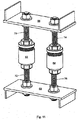
図1は、長方形のコンクリート支柱または向かい合う壁26、28を整列および接合するために使用されている、本発明に係る多数のユニット10、12、14、16、18、20、22、24を示す。本発明に係るユニットの必要数が、特定用途における負荷耐久仕様および安全要件によって決まることは明白である。ここでは、多数のユニットが、コンクリート支柱または壁を整列および接合させるために用いられている。
FIG. 1 shows a number of
図2は、上部建築要素30および下部建築要素32を接合および整列させるために使用されている本発明を示している。ここでは、ネジ切りされた向かい合うスタッド34、36が実質的に整列されており、上側筒状部材38と下側筒状部材40が締め付けられて調整ナット(図示せず)を包み込んでいる。この例では、コンクリートがユニットの周囲に注がれてユニットを封止するときに、第1筒状部材のフランジ38aが、コンクリートの中での固定力やグリップを増強する。
FIG. 2 illustrates the present invention being used to join and align the
別の側面では、フランジ38aはまた、建築要素から突出し、かつ外面をネジ切りされた筒状部のみを残して、筒状部材38を建築要素30の中へ埋め込むことが必要な場合に、筒状部材38を端面に対して固定する手段となる。
In another aspect, the
第1および第2の(すなわち、上側および下側の)筒状部材は、オープンエンドスパナで締め付けができるように、どちらも六角形部分38b、40aを有している。
The first and second (ie, upper and lower) tubular members both have
図2と同じ参照番号を用いている図3、図4、図5は、器具の異なった角度からの様々な見え方を示す。すべての図において、第1筒状部材38と第2筒状部材40は、きつくネジ締めされており、それによって、定位置に調整ナット(図示せず)を包み込んでロックしている。これらのすべての図において、ネジ切りされた向かい合うスタッド34、36は実質的に同軸に整列されていることが明白である。
3, 4 and 5 using the same reference numbers as in FIG. 2 show the various views of the instrument from different angles. In all the drawings, the first
図4にも示されるように、ネジ切りされた向かい合う棒34および36に対して第1および第2の筒状部材(それぞれ38および40)をしっかり固定するために、それらの筒状部材に対して締め付けられるロックナット38cおよび40bをさらに設けてもよい。
As shown also in FIG. 4, to secure the first and second tubular members (38 and 40, respectively) against the threaded opposing
図6および図7は本発明の立面断面図であり、整列して向かい合うスタッド41、43と、ずれて向かい合うスタッド51、53をそれぞれ示している。図6の断面図では、第2筒状部材42の内面ネジ山42aが、第1筒状部材44の外面ネジ山44aと係合しており、それによって両方の筒状部材が締め付けられ、重なり合って、調整ナット46を定位置にロックしている様子が示されている。調整ナットと共に図示されている上側ワッシャ48および下側ワッシャ50は、調整ナットの回転を容易にし、それぞれ、第1筒状部材の自由端44bおよび第2筒状部材42bに対する支圧強度を強化する。図7に示された器具では、向かい合うスタッド51、53の整列がわずかにずれている。ここで、第2係合部材54の終端壁の穴54aは、向かい合うスタッド部材51、53の整列のずれを収容するのに十分な直径を有していることが理解されるであろう。ワッシャ58、60とナットが、第1係合部材60の自由端60aを固定するのに十分な直径または寸法を有しているので、調整ナット56のネジとしての持ち上げ機能が失われることはない。終端壁の穴54aの寸法のおかげで、第1係合部材60および第2係合部材54はスタッド51の軸に沿って整列することが可能になり、締め付けられることで定位置に調整ナット56を包み込んでロックできる。前述したように、その後、コンクリートを注いで器具を恒久的に封止することができる。
FIGS. 6 and 7 are elevational sectional views of the present
図8、図9、図10は、本発明に係る好ましい器具の分解図である。図6および図7と同じ参照番号が用いられている。典型的にはコンクリートの支柱または杭である、整列および接合されるべき建築要素(図示せず)には、それぞれ、図示された向かい合う第1および第2のネジ切りされたスタッド41、43が設けられる。外面ネジ山44aを有する第1のネジ切りされた係合部材44は、第1スタッド41のネジに嵌められている。第2係合部材42の終端壁には、第1係合部材の自由端の直径と好ましくは同一かそれ以上の直径を有する穴42cが設けられており、第2係合部材42は第2スタッド43の上を滑走させられる。第2係合部材の内面ネジ山42aは、第1係合要素の外面ネジ山44aと係合するように構成されている。次に、調整ナット46とワッシャ48、50を備える調整手段が、第2スタッド43のネジに嵌められる。次に、ワッシャ48が第1係合部材44の自由端44bと接触させられ、建築要素間に所望の整列が達成されるまで調整ナットをさらに回すことにより、調整ナットがネジとして第1ロック部材を効果的に持ち上げる。次に、第2係合部材42が第1係合部材44と係合させられ、両係合部材が一緒にネジ締めされる。第2係合部材は、第1係合部材に対して締め付けられるときに、調整ナット46を包み込んでロックする。次に、例えば床になるコンクリートが器具の周りに注がれるなど、それぞれの建築要素の間の空間にコンクリートが注入されることによって、器具は定位置にしっかり固定される。
8, 9 and 10 are exploded views of a preferred instrument according to the present invention. The same reference numerals as in FIGS. 6 and 7 are used. Building elements to be aligned and joined, typically concrete posts or piles (not shown), are each provided with opposing first and second threaded
図11は、向かい合う構造的鋼鉄要素66、68を接合および整列させるための、本発明に係る好ましい一対の器具62、64を示す。ネジ切りされた棒70、72、74、76は桁66、68の端部フランジにボルト留めされている。要素を整列させるのに用いられるユニットの数が、建造物の要件、および、連結されるべき建築要素の大きさによって変わることは理解されるであろう。同様に、本発明に係る好ましい器具は、構造的鋼鉄要素をコンクリート要素に連結する場合にも用いることができる。例えば、ネジ切りされたスタッド(留め具ボルト)を埋設されたコンクリートの基礎に、ベースプレート付き鋼鉄支柱を連結するような場合である。
FIG. 11 shows a preferred pair of
図12、図13、図14、図15は、好ましいスタッドまたは棒整列手段を示す。中央突起80aを有するキャップ部材80は、スタッド82の端部に嵌めこむことができるように構成されている。突起80aは、向かい側のスタッド86または棒の係合筒状部材84の中央凹部84aに挿入できるように構成されているので、図13および図14に示すように、向かい合うスタッド82および86は実質的に整列することができる。 12, 13, 14 and 15 show preferred stud or bar alignment means. The cap member 80 having the central protrusion 80 a is configured to be fitted into the end portion of the stud 82. Since the protrusion 80a is configured to be inserted into the opposite stud 86 or the central recess 84a of the rod engaging tubular member 84, the opposing studs 82 and 86 are substantially as shown in FIGS. Can be aligned.
キャップ80は、スタッド82の端部に摩擦溶接されるか、スタッド82のネジに嵌められる。 The cap 80 is friction welded to the end of the stud 82 or is fitted on a screw of the stud 82.
取り外しが可能なクリップ90は、キャップの突起80aを中央凹部84aに挿入して向かい合うスタッドまたは棒82および86を実質的に整列させる際にスタッド82をつかみ、それによって、スタッド82の側の係合筒状部材88をキャップのある端部から離間するように一時的に支持することができる。クリップ90を取り外した後は、図15に示すように、筒状部材84および88が一緒にネジ締めされる。
The
これまで、本発明の実施例を図示してきたが、これらのすべて、および、当業者にとって明白となりうる他の改変や変形例も同様に本発明の広範な範囲および領域に含まれる、ということは当然理解されるべきである。 While the embodiments of the present invention have been illustrated, it should be understood that all of these and other modifications and variations that may be apparent to those skilled in the art are also within the broad scope and area of the present invention. Of course it should be understood.
さらに、本明細書を通して、「備える」および「有する」の語は「含む」の語と同様に広い意味を持つものとして理解されるべきであり、ある言及された完成品、ステップ、完成品またはステップの群を包含する意図があったとしても、他のいかなる完成品、ステップ、完成品またはステップの群を排除する意図も持たないと理解されるべきである。この定義はまた、「備える」および「有する」の語の活用形である「備えて」「備えた」「有して」「有した」などにも当てはまる。 Further, throughout this specification, the terms “comprising” and “having” are to be understood as having the same broad meaning as the word “comprising”, and certain finished products, steps, finished products or It should be understood that any intention to encompass a group of steps is not intended to exclude any other finished product, step, finished product or group of steps. This definition also applies to the use forms of the words “comprising” and “having” such as “having”, “having”, “having”, “having”.
加えて、建築あるいは建造物の「要素」の語は、コンクリートの杭、支柱、壁、床、その他の鉄筋コンクリート構造体を含むとともに、鋼鉄梁、鋼鉄桁、その他の鋼鉄構造体を含むものとして理解される。スタッドという語に関しては、ここで説明した建築要素から突出する補強棒すなわち鉄筋も同様に含む。特定の実施例の説明の中で、ネジ切りされたスタッドと言ったときは、外面をネジ切りされた補強棒を意味しうるし、またその逆もありうる。
「ネジとして持ち上げる」という用語は、典型的には、下方にある他の支柱または梁の上端に配列させられている支柱または梁の重量のような、向かい合う要素の圧縮力に対抗して離間させる、または押し上げるという意味を含む。
In addition, the term “element” in an architecture or building is understood to include concrete piles, columns, walls, floors, other reinforced concrete structures, as well as steel beams, steel girders, and other steel structures. Is done. With respect to the term stud, this also includes reinforcing bars or rebars protruding from the building elements described here. In the description of a particular embodiment, reference to a threaded stud can mean a reinforcing bar threaded on the outer surface and vice versa.
The term “lifting as a screw” is typically spaced against the compressive forces of opposing elements, such as the weight of a post or beam arranged at the top of another underlying post or beam. Or the meaning of pushing up.
Claims (15)
前記第1の要素と整列および接合させられるように、第2の要素に埋め込まれるとともに前記第2の要素から突出する、第2のネジ切りされたスタッドと、
前記第1のスタッドに固定的に取り付けられるとともに、ネジ切りされた外壁を有する第1の係合部材と、
前記第1の係合部材にネジ締めされるように構成された内面ネジ山を有する第2の係合部材であって、前記第2の係合部材が前記第2のスタッドの上を自由に滑走できるようにするための穴がある終端壁を有し、前記穴の寸法は前記スタッドの整列のずれ分を収容するのに必要となる許容範囲を決定する、第2の係合部材と、
前記第2のスタッドにネジ係合することができ、前記第1の係合部材の自由端と接触する調整ナットであって、前記調整ナットと前記第1の係合部材は互いに対して回転可能であり、前記第1の係合部材の前記自由端に対して前記調整ナットを回転させるか又は前記調整ナットに対して前記第1の係合部材の前記自由端を回転させることによって前記第1および第2の要素が整列し、前記第2の係合部材は前記第1の係合部材にネジ締めされるときに前記調整ナットを定位置に包み込んでロックする、調整ナットと、
を共に備える、コンクリートの支柱、壁、梁、または、構造的鉄鋼部品を含む建築要素を整列および接合するための器具。 A first threaded stud embedded in the first element and projecting from an end of the first element;
A second threaded stud embedded in and projecting from the second element to be aligned and joined to the first element;
A first engagement member fixedly attached to the first stud and having a threaded outer wall;
A second engagement member having an internal thread configured to be screwed to the first engagement member, the second engagement member freely over the second stud. A second engagement member having a termination wall with a hole for allowing sliding, the dimension of the hole determining the tolerance required to accommodate the misalignment of the stud;
An adjustment nut that is threadably engageable with the second stud and contacts a free end of the first engagement member, the adjustment nut and the first engagement member being rotatable relative to each other And rotating the adjustment nut relative to the free end of the first engagement member or rotating the free end of the first engagement member relative to the adjustment nut. And an adjustment nut, wherein the second element is aligned and the second engagement member wraps and locks the adjustment nut in place when screwed onto the first engagement member;
An instrument for aligning and joining building elements, including concrete columns, walls, beams, or structural steel parts.
a)前記第1のスタッドに前記第1の係合部材をネジ係合によって取り付けるステップと、
b)向かい側の前記第2のスタッドの上で前記第2の係合部材を滑走させるステップと、
c)前記第2のスタッドに前記調整ナットをネジ係合させ、前記第1の係合部材の前記自由端に前記調整ナットを接触させるステップと、
d)前記第1および第2の要素を整列させるために、前記調整ナットを前記第1の係合部材の自由端に対して回転させるか又は前記第1の係合部材の前記自由端を前記調整ナットに対して回転させるステップと、
e)所望の整列を得た後、前記第2の係合部材を前記第1の係合部材とネジ係合し、前記第2および第1の係合部材を一緒に締め付けることによって、前記調整ナットを定位置に包み込んでロックするステップと、
を有する、方法。 A method of aligning reinforced concrete elements and joining their studs using the instrument of any one of claims 1-10,
a) attaching the first engagement member to the first stud by screw engagement;
b) sliding the second engagement member over the second stud on the opposite side;
c) threading engagement of the adjustment nut to the second stud and contacting the adjustment nut to the free end of the first engagement member;
d) rotating the adjustment nut relative to the free end of the first engagement member or aligning the free end of the first engagement member to align the first and second elements; Rotating with respect to the adjusting nut;
e) after obtaining the desired alignment, the adjustment is achieved by screwing the second engagement member with the first engagement member and clamping the second and first engagement members together. Wrapping the nut in place and locking it,
Having a method.
前記第1の要素と整列および接合させられるように、第2の要素に埋め込まれるとともに前記第2の要素から突出する、第2のネジ切りされたスタッドと、
前記第1のスタッドに固定的に取り付けられるとともに、ネジ切りされた外壁を有する第1の係合部材と、
前記第1の係合部材にネジ締めされるように構成された内面ネジ山を有する第2の係合部材であって、前記第2の係合部材が前記第2のスタッドの上を自由に滑走できるようにするための穴がある終端壁を有し、前記穴の寸法は前記スタッドの整列のずれ分を収容するのに必要となる許容範囲を決定する、第2の係合部材と、
前記第2のスタッドの端部に嵌合されたキャップ部材であって、前記キャップ部材は前記第1の係合部材が前記キャップ部材に対して回転可能であり、それによって、前記第1および前記第2の係合部材を一緒にネジ締めする前に前記第1および第2のスタッドが実質的に整列するように、前記第1の係合部材の中央凹部に挿入されるように構成された中央突起を有するキャップ部材と、
を備える、コンクリートの支柱、壁、梁、または、構造的鉄鋼部品を含む建築要素を整列および接合するための器具。 A first threaded stud embedded in the first element and projecting from an end of the first element;
A second threaded stud embedded in and projecting from the second element to be aligned and joined to the first element;
A first engagement member fixedly attached to the first stud and having a threaded outer wall;
A second engagement member having an internal thread configured to be screwed to the first engagement member, the second engagement member freely over the second stud. A second engagement member having a termination wall with a hole for allowing sliding, the dimension of the hole determining the tolerance required to accommodate the misalignment of the stud;
A cap member is fitted to an end portion of the second stud, the cap member is rotatable first engaging member relative to the cap member, whereby said first and said Configured to be inserted into a central recess of the first engagement member such that the first and second studs are substantially aligned prior to screwing the second engagement member together A cap member having a central protrusion;
An apparatus for aligning and joining building elements, including concrete columns, walls, beams, or structural steel parts.
a)前記第1のスタッドに前記第1の係合部材をネジ係合によって取り付けるステップと、
b)向かい側の前記第2のスタッドの上で前記第2の係合部材を滑走させるステップと、
c)キャップ部材を前記第2のスタッドに取り付け、前記キャップ部材を前記第1の係合部材の自由端に接触させるステップと、
d)前記第1の係合部材を前記キャップ部材に対して回転させ、前記第1及び第2のスタッドを整列させるステップと、
e)所望の整列を得た後、前記第2の係合部材を前記第1の係合部材とネジ係合し、前記第2および第1の係合部材を一緒に締め付けることによって、前記キャップ部材を定位置に包み込んでロックするステップと、
を有する、方法。 A method for aligning reinforced concrete elements and joining their studs using the instrument of any one of claims 12-14, comprising:
a) attaching the first engagement member to the first stud by screw engagement;
b) sliding the second engagement member over the second stud on the opposite side ;
c ) attaching a cap member to the second stud and contacting the cap member with a free end of the first engaging member;
d ) rotating the first engagement member relative to the cap member to align the first and second studs;
e ) after obtaining the desired alignment, the second engagement member is threadedly engaged with the first engagement member, and the second and first engagement members are tightened together to thereby cap the cap Wrapping and locking the member in place;
Having a method.
Applications Claiming Priority (3)
| Application Number | Priority Date | Filing Date | Title |
|---|---|---|---|
| AU2012902731 | 2012-06-27 | ||
| AU2012902731A AU2012902731A0 (en) | 2012-06-27 | Combination reinforcing coupler and column alignment device | |
| PCT/AU2013/000694 WO2014000038A1 (en) | 2012-06-27 | 2013-06-26 | Combination reinforcing coupler and column alignment device |
Publications (3)
| Publication Number | Publication Date |
|---|---|
| JP2015521698A JP2015521698A (en) | 2015-07-30 |
| JP2015521698A5 JP2015521698A5 (en) | 2016-08-12 |
| JP6340001B2 true JP6340001B2 (en) | 2018-06-06 |
Family
ID=49781952
Family Applications (1)
| Application Number | Title | Priority Date | Filing Date |
|---|---|---|---|
| JP2015518727A Active JP6340001B2 (en) | 2012-06-27 | 2013-06-26 | Combination reinforcing coupler and column alignment device |
Country Status (17)
| Country | Link |
|---|---|
| US (1) | US9840844B2 (en) |
| EP (1) | EP2867422B1 (en) |
| JP (1) | JP6340001B2 (en) |
| KR (1) | KR102166001B1 (en) |
| CN (1) | CN104520518B (en) |
| BR (1) | BR112014032519B1 (en) |
| CA (1) | CA2877186C (en) |
| DK (1) | DK2867422T3 (en) |
| EA (1) | EA029465B1 (en) |
| ES (1) | ES2794473T3 (en) |
| HK (1) | HK1209166A1 (en) |
| MY (1) | MY171229A (en) |
| NZ (1) | NZ627596A (en) |
| SG (1) | SG11201408669VA (en) |
| TW (1) | TWI601871B (en) |
| WO (1) | WO2014000038A1 (en) |
| ZA (1) | ZA201500556B (en) |
Families Citing this family (18)
| Publication number | Priority date | Publication date | Assignee | Title |
|---|---|---|---|---|
| CN103821230A (en) * | 2014-02-27 | 2014-05-28 | 王睿敏 | Reinforced concrete structure connection component, manufacturing method and construction method thereof |
| KR101456825B1 (en) * | 2014-05-21 | 2014-10-31 | 김용근 | Reinforcing bar coupler with pair of locking piece and connecting method of pre-assembled rebar cage using thereof |
| ES2835329T3 (en) * | 2015-06-03 | 2021-06-22 | Onguard Group Ltd | Clamping mount |
| FR3043111B1 (en) * | 2015-10-28 | 2019-08-30 | Saint-Gobain Isover | DETERMINING DEVICE FOR DOUBLING A STRUCTURE |
| US9909300B2 (en) * | 2016-03-16 | 2018-03-06 | Toyota Motor Engineering & Manufacturing North America, Inc. | Truss clamp assemblies |
| CN105908974A (en) * | 2016-04-13 | 2016-08-31 | 江苏华江建设集团有限公司 | Method of steel-bar sleeve grouting connection construction for vertical precast concrete component |
| JP6750158B2 (en) * | 2016-04-22 | 2020-09-02 | エム3エス アイピー ピーティーワイ リミテッド アズ トラスティー フォー エム3エス アイピー トラスト | Adjustable mini jack coupler and usage |
| US10041252B1 (en) * | 2016-07-28 | 2018-08-07 | Steven James Bongiorno | Bar sleeve |
| WO2018152341A1 (en) * | 2017-02-15 | 2018-08-23 | Tindall Corporation | Methods and apparatuses for constructing a concrete structure |
| US10392804B2 (en) * | 2017-04-10 | 2019-08-27 | Brian Butts | Delay anchor |
| CN108612224A (en) * | 2018-04-29 | 2018-10-02 | 山东德建集团有限公司 | Exposed inversion reinforcing bar grout sleeve concrete shear force wall and construction method |
| CN109057169B (en) * | 2018-09-10 | 2021-04-13 | 安徽省英剑科技发展有限公司 | Steel bar connecting structure of prefabricated cement component |
| WO2020053745A1 (en) * | 2018-09-10 | 2020-03-19 | T & R Interior Systems Limited | A bracket |
| US11286683B2 (en) * | 2019-03-12 | 2022-03-29 | Idaho State University | Ductile connections for pre-formed construction elements |
| GB2586847A (en) * | 2019-09-05 | 2021-03-10 | Cintec International Ltd | Anchor rod coupling joint |
| US11951652B2 (en) | 2020-01-21 | 2024-04-09 | Tindall Corporation | Grout vacuum systems and methods |
| USD1033212S1 (en) * | 2020-06-11 | 2024-07-02 | Seoul National University R&Db Foundation | Reinforcing bar coupler |
| US11619048B1 (en) * | 2021-10-20 | 2023-04-04 | N C Coupler Llc | Non-slip reinforcing bar coupler |
Family Cites Families (31)
| Publication number | Priority date | Publication date | Assignee | Title |
|---|---|---|---|---|
| DE1784807C3 (en) * | 1968-09-20 | 1974-04-04 | Strabag Bau-Ag, 5000 Koeln | Butt joint of the longitudinal reinforcement bars of prefabricated structural parts made of concrete |
| DE1802881C3 (en) * | 1968-10-12 | 1973-12-06 | Strabag Bau-Ag, 5000 Koeln | Method and device for Her put a butt joint of the longitudinal reinforcement rod of prefabricated construction work stubs made of concrete |
| US3820293A (en) * | 1971-12-29 | 1974-06-28 | Tokyo Plywood Kk | Framed structural member and board structure composed of short timbers assembled |
| DE2216302A1 (en) * | 1972-04-05 | 1973-10-18 | Zueblin Ag | FASTENING ELEMENT FOR REINFORCEMENT BARS OF PRECAST CONCRETE ELEMENTS |
| CA988317A (en) * | 1973-02-28 | 1976-05-04 | Michel Bouchard | Anchoring device for securing and positioning equipment |
| US3898770A (en) * | 1974-11-25 | 1975-08-12 | Speedfam Corp | Lapping fixture reference plate assembly |
| JPS5439290Y2 (en) * | 1975-04-17 | 1979-11-21 | ||
| FR2668558B1 (en) * | 1990-10-29 | 1993-08-13 | Arteon Marcel | CONNECTION DEVICE FOR JOINING END TO END TWO BARS. |
| FR2668800B2 (en) * | 1990-10-29 | 1994-05-20 | Arteon Marcel | CONNECTION DEVICE FOR JOINING END TO END TWO BARS. |
| GB2255385A (en) | 1991-05-02 | 1992-11-04 | Lin Ming Hui | A wedge-chuck connector |
| JPH05321408A (en) * | 1992-05-18 | 1993-12-07 | Daiwa House Ind Co Ltd | Reinforcement joint |
| US5305573A (en) * | 1992-06-03 | 1994-04-26 | Baumann Hanns U | Energy dissipating connector |
| JPH09268887A (en) * | 1996-04-03 | 1997-10-14 | P C Kk | Connecting and fixing device for pre-fabricated concrete member |
| NL1005655C2 (en) * | 1997-03-27 | 1998-09-29 | Hendrik Van De Riet | System for connecting objects. |
| JPH1171860A (en) * | 1997-06-27 | 1999-03-16 | Kaiee Techno:Kk | Concrete block connecting structure and connector used therefor |
| CN1096535C (en) * | 1997-06-27 | 2002-12-18 | 株式会社皆荣技术 | Connection structure of concrete block and connector therefor |
| DE29721146U1 (en) * | 1997-11-28 | 1999-04-01 | Max Bögl Bauunternehmung GmbH & Co KG, 92318 Neumarkt | Connector |
| JP2000179053A (en) * | 1998-12-18 | 2000-06-27 | Kaieitechno Co Ltd | Connecting metal |
| JP2000320023A (en) * | 1999-05-13 | 2000-11-21 | Kaieitechno Co Ltd | Connection structure of concrete product |
| JP4347988B2 (en) * | 2000-03-28 | 2009-10-21 | カイエー共和コンクリート株式会社 | Coupler |
| NL1020069C1 (en) * | 2002-02-27 | 2002-07-22 | Barfix Bermuda Ltd | Method and device for joining reinforcing steel. |
| JP3851590B2 (en) * | 2002-05-23 | 2006-11-29 | エスティーエンジニアリング株式会社 | Preceding ground mountain consolidation method using self-drilling bolt and FRP bolt |
| KR100625599B1 (en) | 2002-07-24 | 2006-09-20 | 삼성전자주식회사 | Washing machine having supply device of sterilization water |
| JP3764883B2 (en) * | 2003-06-11 | 2006-04-12 | 旭コンクリート工業株式会社 | Concrete product connection structure and method |
| US7390032B2 (en) * | 2003-08-01 | 2008-06-24 | Sonstone Corporation | Tubing joint of multiple orientations containing electrical wiring |
| KR20070054417A (en) * | 2005-11-23 | 2007-05-29 | 김용근 | Threaded sleeve for coupling the threaded deformed reinforcing bars |
| KR200409526Y1 (en) * | 2005-11-23 | 2006-03-03 | 김용근 | Threaded sleeve for coupling the threaded deformed reinforcing bars |
| KR100914049B1 (en) * | 2009-05-07 | 2009-08-26 | 최정환 | Connections bending type rebar coupler |
| DE102010013771A1 (en) | 2010-03-15 | 2011-09-15 | Bilfinger Berger Ag | Device for coupling two components |
| CN101906893A (en) * | 2010-07-21 | 2010-12-08 | 彭成中 | Shock isolation method and splicing device of buildings |
| US20120097816A1 (en) * | 2010-10-20 | 2012-04-26 | D Three Enterprises, Llc | Combination mounting and grounding clip |
-
2013
- 2013-06-26 DK DK13810601.8T patent/DK2867422T3/en active
- 2013-06-26 BR BR112014032519-7A patent/BR112014032519B1/en active IP Right Grant
- 2013-06-26 JP JP2015518727A patent/JP6340001B2/en active Active
- 2013-06-26 NZ NZ627596A patent/NZ627596A/en unknown
- 2013-06-26 ES ES13810601T patent/ES2794473T3/en active Active
- 2013-06-26 WO PCT/AU2013/000694 patent/WO2014000038A1/en active Application Filing
- 2013-06-26 MY MYPI2014703991A patent/MY171229A/en unknown
- 2013-06-26 KR KR1020157001114A patent/KR102166001B1/en active IP Right Grant
- 2013-06-26 TW TW102122612A patent/TWI601871B/en active
- 2013-06-26 US US14/410,366 patent/US9840844B2/en active Active
- 2013-06-26 EA EA201590120A patent/EA029465B1/en unknown
- 2013-06-26 EP EP13810601.8A patent/EP2867422B1/en active Active
- 2013-06-26 CA CA2877186A patent/CA2877186C/en active Active
- 2013-06-26 SG SG11201408669VA patent/SG11201408669VA/en unknown
- 2013-06-26 CN CN201380033675.XA patent/CN104520518B/en active Active
-
2015
- 2015-01-26 ZA ZA2015/00556A patent/ZA201500556B/en unknown
- 2015-10-12 HK HK15109919.2A patent/HK1209166A1/en unknown
Also Published As
| Publication number | Publication date |
|---|---|
| CA2877186A1 (en) | 2014-01-03 |
| SG11201408669VA (en) | 2015-01-29 |
| NZ627596A (en) | 2015-07-31 |
| BR112014032519B1 (en) | 2021-02-23 |
| KR20150029706A (en) | 2015-03-18 |
| US9840844B2 (en) | 2017-12-12 |
| EP2867422A1 (en) | 2015-05-06 |
| BR112014032519A2 (en) | 2017-06-27 |
| EP2867422A4 (en) | 2016-03-23 |
| JP2015521698A (en) | 2015-07-30 |
| CN104520518B (en) | 2018-12-14 |
| ZA201500556B (en) | 2016-03-30 |
| CA2877186C (en) | 2020-01-28 |
| TWI601871B (en) | 2017-10-11 |
| US20150292207A1 (en) | 2015-10-15 |
| MY171229A (en) | 2019-10-03 |
| EA201590120A1 (en) | 2015-06-30 |
| HK1209166A1 (en) | 2016-03-24 |
| ES2794473T3 (en) | 2020-11-18 |
| EP2867422B1 (en) | 2020-03-11 |
| TW201404980A (en) | 2014-02-01 |
| DK2867422T3 (en) | 2020-06-15 |
| CN104520518A (en) | 2015-04-15 |
| WO2014000038A1 (en) | 2014-01-03 |
| AU2013284347A1 (en) | 2014-08-14 |
| EA029465B1 (en) | 2018-03-30 |
| KR102166001B1 (en) | 2020-10-16 |
Similar Documents
| Publication | Publication Date | Title |
|---|---|---|
| JP6340001B2 (en) | Combination reinforcing coupler and column alignment device | |
| JP2015521698A5 (en) | ||
| US10352046B2 (en) | Adjustable compact lifting coupler and method of use | |
| CA2770604C (en) | A bar coupler | |
| WO2008025050A1 (en) | Formwork apparatus and method of erecting formwork apparatus | |
| US8341893B2 (en) | Seismic coupler | |
| KR20180037561A (en) | Apparatus and method for reinforcing concrete structure | |
| AU2013284347B2 (en) | Combination reinforcing coupler and column alignment device | |
| JP2008163652A (en) | Column base structure of wooden building, and fitting for it | |
| KR20140127094A (en) | Temporary column structure and temporary scaffold | |
| KR20140137593A (en) | Device for connecting end portion of linear member for seismic retrofit of mansory wall | |
| KR20190076660A (en) | Coupling device and method for preformed bar arrangement using threaded reinforcing bars | |
| CN117803136A (en) | Prefabricated component connecting sleeve assembly with threaded connecting ribs | |
| CN117780021A (en) | Connecting piece for connecting members with connecting screw holes | |
| CN117803137A (en) | Component with threaded connecting ribs, connecting structure and application method | |
| AU2014202237A1 (en) | Formwork apparatus and method of erecting formwork apparatus |
Legal Events
| Date | Code | Title | Description |
|---|---|---|---|
| A521 | Request for written amendment filed |
Free format text: JAPANESE INTERMEDIATE CODE: A523 Effective date: 20160620 |
|
| A621 | Written request for application examination |
Free format text: JAPANESE INTERMEDIATE CODE: A621 Effective date: 20160620 |
|
| A977 | Report on retrieval |
Free format text: JAPANESE INTERMEDIATE CODE: A971007 Effective date: 20161214 |
|
| A131 | Notification of reasons for refusal |
Free format text: JAPANESE INTERMEDIATE CODE: A131 Effective date: 20161220 |
|
| A601 | Written request for extension of time |
Free format text: JAPANESE INTERMEDIATE CODE: A601 Effective date: 20170310 |
|
| A521 | Request for written amendment filed |
Free format text: JAPANESE INTERMEDIATE CODE: A523 Effective date: 20170515 |
|
| A131 | Notification of reasons for refusal |
Free format text: JAPANESE INTERMEDIATE CODE: A131 Effective date: 20171024 |
|
| A521 | Request for written amendment filed |
Free format text: JAPANESE INTERMEDIATE CODE: A523 Effective date: 20171227 |
|
| TRDD | Decision of grant or rejection written | ||
| A01 | Written decision to grant a patent or to grant a registration (utility model) |
Free format text: JAPANESE INTERMEDIATE CODE: A01 Effective date: 20180417 |
|
| A61 | First payment of annual fees (during grant procedure) |
Free format text: JAPANESE INTERMEDIATE CODE: A61 Effective date: 20180511 |
|
| R150 | Certificate of patent or registration of utility model |
Ref document number: 6340001 Country of ref document: JP Free format text: JAPANESE INTERMEDIATE CODE: R150 |
|
| S111 | Request for change of ownership or part of ownership |
Free format text: JAPANESE INTERMEDIATE CODE: R313113 |
|
| S531 | Written request for registration of change of domicile |
Free format text: JAPANESE INTERMEDIATE CODE: R313531 |
|
| R350 | Written notification of registration of transfer |
Free format text: JAPANESE INTERMEDIATE CODE: R350 |
|
| R250 | Receipt of annual fees |
Free format text: JAPANESE INTERMEDIATE CODE: R250 |
|
| R250 | Receipt of annual fees |
Free format text: JAPANESE INTERMEDIATE CODE: R250 |
|
| R250 | Receipt of annual fees |
Free format text: JAPANESE INTERMEDIATE CODE: R250 |
|
| R250 | Receipt of annual fees |
Free format text: JAPANESE INTERMEDIATE CODE: R250 |