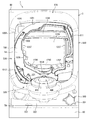
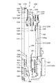
本発明の一実施形態であるパチンコ機1について、図面を参照して詳細に説明する。まず、図1、図2を参照して本実施形態のパチンコ機1の全体構成について説明する。図1は本発明の一実施形態であるパチンコ機の正面図であり、図2は本体枠から扉枠を開放させると共に、外枠から本体枠を開放させた状態で前から見たパチンコ機の斜視図である。
A pachinko machine 1 according to an embodiment of the present invention will be described in detail with reference to the drawings. First, the overall configuration of the pachinko machine 1 according to the present embodiment will be described with reference to FIGS. 1 and 2. FIG. 1 is a front view of a pachinko machine according to an embodiment of the present invention, and FIG. 2 shows a pachinko machine viewed from the front with the door frame opened from the main body frame and the main body frame opened from the outer frame. It is a perspective view.
本実施形態のパチンコ機1は、遊技ホールの島設備(図示しない)に設置される枠状の外枠2と、外枠2の前面を開閉可能に閉鎖する扉枠3と、扉枠3を開閉可能に支持していると共に外枠2に開閉可能に取付けられている本体枠4と、本体枠4に前側から着脱可能に取付けられると共に扉枠3を通して遊技者側から視認可能とされ遊技者によって遊技球が打込まれる遊技領域5aを有した遊技盤5と、を備えている。
A pachinko machine 1 according to the present embodiment includes a frame-shaped outer frame 2 installed in an island facility (not shown) of a game hall, a door frame 3 that closes the front surface of the outer frame 2 so that it can be opened and closed, and a door frame 3. A main body frame 4 that is supported so as to be opened and closed, and is attached to the outer frame 2 so as to be openable and closable, and is detachably attached to the main body frame 4 from the front side, and is visible from the player side through the door frame 3. And a game board 5 having a game area 5a into which a game ball is driven.
[外枠]
前記外枠2は、左枠部材(符合が付されていないものは図示を省略している。以下同じ。)及び右枠部材40の下端同士を連結し下枠部材20の前側に取付けられる幕板部材50と、上枠部材10の正面視左端部側に取付けられている外枠側上ヒンジ部材60と、幕板部材50の正面視左端側上部と左枠部材とに取付けられている外枠側下ヒンジ部材70と、を備えている。外枠2の外枠側上ヒンジ部材60と外枠側下ヒンジ部材70とによって、本体枠4及び扉枠3が開閉可能に取付けられている。
[Outer frame]
The outer frame 2 is a curtain that is attached to the front side of the lower frame member 20 by connecting the lower ends of the left frame member (not shown with the reference numerals omitted. The same applies hereinafter) and the lower end of the right frame member 40. A plate member 50, an outer frame side upper hinge member 60 attached to the left end portion of the upper frame member 10 when viewed from the front, and an outer portion attached to the upper left end portion of the curtain plate member 50 and the left frame member. Frame-side lower hinge member 70. The main frame 4 and the door frame 3 are attached to be openable and closable by an outer frame side upper hinge member 60 and an outer frame side lower hinge member 70 of the outer frame 2.
[扉枠]
パチンコ機1の扉枠3は、図1及び図2等に示すように、正面視の外形が上下に延びた四角形で前後に貫通している貫通口111を有した枠状の扉枠ベースユニット100と、扉枠ベースユニット100の貫通口111よりも下側で前面右下隅に取付けられており遊技球を遊技盤5の遊技領域5a内へ打込むために遊技者が操作可能なハンドルユニット300と、扉枠ベースユニット100の貫通口111よりも下側で前面下部に取付けられている皿ユニット320と、皿ユニット320の中央に取付けられており遊技領域5a内に遊技球が打込まれることで変化する遊技状態に応じて遊技者に参加型の演出を提示することが可能な演出操作ユニット400と、皿ユニット320の上側で扉枠ベースユニット100における貫通口111よりも左側の前面左部に取付けられている扉枠左サイドユニット530と、皿ユニット320の上側で扉枠ベースユニット100における貫通口111よりも右側の前面右部に取付けられている扉枠右サイドユニット550と、扉枠左サイドユニット530及び扉枠右サイドユニット550の上側で扉枠ベースユニット100における貫通口111よりも上側の前面上部に取付けられている扉枠トップユニット570と、を備えている。
[Door frame]
As shown in FIGS. 1 and 2, the door frame 3 of the pachinko machine 1 is a frame-shaped door frame base unit having a through-hole 111 penetrating back and forth in a quadrilateral shape whose front view extends vertically. 100 and a handle unit 300 that is attached to the lower right front corner of the door frame base unit 100 below the through-hole 111 and can be operated by the player to drive the game ball into the game area 5a of the game board 5. And a tray unit 320 attached to the lower front part below the through-hole 111 of the door frame base unit 100, and a game ball being driven into the game area 5a attached to the center of the tray unit 320. From the operation unit 400 capable of presenting a participation type effect to the player according to the game state that changes in the above, and the through-hole 111 in the door frame base unit 100 above the plate unit 320 A door frame left side unit 530 attached to the left front portion of the left side, and a door frame right side unit attached to the front right portion of the door frame base unit 100 on the right side of the through hole 111 above the plate unit 320. 550, and a door frame top unit 570 that is attached to the upper part of the front side of the door frame base unit 100 and above the through-hole 111 above the door frame left side unit 530 and the door frame right side unit 550. .
[扉枠ベースユニット]
扉枠3の扉枠ベースユニット100は、正面視の外形が上下に延びた長方形(四角形)で前後に貫通している貫通口111を有した板状の扉枠ベース110と、扉枠ベース110の後側に取付けられている枠状の補強ユニット130と、補強ユニット130の正面視左端側の上下両端に取付けられており本体枠4に対してヒンジ回転可能に取付けられる扉枠側上ヒンジ部材及び扉枠側下ヒンジ部材と、扉枠ベース110の後面に取付けられ貫通口111を閉鎖するガラスユニット190と、ガラスユニット190の後面下部を覆う防犯カバー200と、扉枠ベース110の後面に扉枠ベース110を貫通して前方に突出するように取付けられ開閉可能とされている扉枠3と本体枠4、及び本体枠4と外枠2との間を施錠するための開閉シリンダユニット210と、扉枠ベース110の後面下部に取付けられ遊技球を球発射装置680に送るための球送りユニット250と、扉枠ベース110の後面下部に取付けられ球発射装置680により発射されて遊技領域5a内に到達しなかった遊技球を受けて下皿322へ排出させるファールカバーユニット270と、を備えている。
[Door frame base unit]
The door frame base unit 100 of the door frame 3 includes a plate-shaped door frame base 110 having a rectangular shape (rectangular shape) with a front view extending vertically and having a through-hole 111 penetrating in the front-rear direction, and the door frame base 110. A frame-shaped reinforcing unit 130 attached to the rear side, and a door frame-side upper hinge member attached to upper and lower ends on the left end side of the reinforcing unit 130 when viewed from the front and attached to the main body frame 4 so as to be capable of hinge rotation. And a door frame side lower hinge member, a glass unit 190 which is attached to the rear surface of the door frame base 110 and closes the through-hole 111, a security cover 200 which covers the lower rear surface of the glass unit 190, and a door on the rear surface of the door frame base 110. The door frame 3 and the main body frame 4 that are attached so as to protrude forward through the frame base 110 and can be opened and closed, and the opening and closing cylinder for locking between the main body frame 4 and the outer frame 2 A unit 210, a ball feeding unit 250 that is attached to the lower part of the rear face of the door frame base 110 and sends a game ball to the ball launcher 680, and a game that is fired by the ball launcher 680 that is attached to the lower part of the rear face of the door frame base 110. A foul cover unit 270 that receives the game balls that have not reached the region 5a and discharges them to the lower plate 322.
[ハンドルユニット]
扉枠3のハンドルユニット300は、回転可能なハンドル301を遊技者が回転操作することで、上皿321内に貯留されている遊技球を、ハンドル301の回転角度に応じた強さで遊技盤5の遊技領域5a内に打込むことができるものである。
[Handle unit]
The handle unit 300 of the door frame 3 allows the player to rotate the handle 301 that is rotatable, so that the game balls stored in the upper plate 321 can be played with a strength corresponding to the rotation angle of the handle 301. The game area 5a can be driven into five game areas 5a.
[皿ユニット]
扉枠3の皿ユニット320は、扉枠ベースユニット100における扉枠ベース110の前面において貫通口111の下側の部位に取付けられ、前面が前方へ膨出していると共に、左右方向中央の前端に演出操作ユニット400が取付けられる。皿ユニット320は、遊技領域5a内に打込むための遊技球を貯留する上皿321と、上皿321の下側に配置されており上皿321やファールカバーユニット270から供給される遊技球を貯留可能な下皿322と、上皿321に貯留されている遊技球を下皿322へ抜くための上皿球抜きボタン327と、球貸機に投入した現金やプリペイドカードの残金の範囲内で遊技者に遊技球を貸し出すための球貸ボタンと、球貸機から貸出された遊技球の分を差し引いた現金やプリペイドカードを返却させるための返却ボタンと、球貸機に投入した現金やプリペイドカードの残数等を表示する球貸返却表示部と、下皿322内の遊技球を皿ユニット320の下方へ排出するための下皿球抜きボタン333と、を備えている。
[Dish unit]
The dish unit 320 of the door frame 3 is attached to the lower part of the through-hole 111 on the front surface of the door frame base 110 in the door frame base unit 100, and the front surface bulges forward and at the front end in the center in the left-right direction. A production operation unit 400 is attached. The tray unit 320 stores an upper plate 321 for storing game balls to be driven into the game area 5a, and game balls supplied from the upper plate 321 and the foul cover unit 270. Within the range of the lower tray 322 that can be stored, the upper tray ball removal button 327 for removing the game balls stored in the upper tray 321 to the lower tray 322, and the balance of cash or prepaid card that has been put into the ball lending machine A ball lending button for lending a game ball to a player, a return button for returning cash or a prepaid card after deducting the amount of the game ball lending from the ball lending machine, and cash or prepaid being thrown into the ball lending machine A ball rental return display unit for displaying the remaining number of cards and the like, and a lower tray ball removal button 333 for discharging game balls in the lower tray 322 to the lower side of the tray unit 320 are provided.
[演出操作ユニット]
扉枠3の演出操作ユニット400は、皿ユニット320の正面視左右方向中央の前部に取付けられるものであり、遊技者が押圧操作することができる大型の操作ボタン410を備えている。
[Direction operation unit]
The effect operation unit 400 of the door frame 3 is attached to the front portion of the center of the dish unit 320 in the left-right direction and includes a large operation button 410 that can be pressed by the player.
[扉枠左サイドユニット]
扉枠3の扉枠左サイドユニット530は、皿ユニット320の上側で扉枠ベースユニット100における貫通口111よりも左側の前面左部に取付けられ、貫通口111(遊技領域5a)の左外側を装飾するものである。扉枠左サイドユニット530は、発光装飾可能な左ユニット装飾レンズ部材を備えている。
[Door frame left side unit]
The door frame left side unit 530 of the door frame 3 is attached to the front left part of the door frame base unit 100 on the left side of the through hole 111 in the upper side of the plate unit 320, and the left outer side of the through hole 111 (game area 5a). It is something to decorate. The door frame left side unit 530 includes a left unit decorative lens member capable of light emission decoration.
[扉枠右サイドユニット]
扉枠3の扉枠右サイドユニット550は、皿ユニット320の上側で扉枠ベースユニット100における貫通口111よりも右側の前面右部に取付けられ、貫通口111(遊技領域5a)の右外側を装飾するものである。この扉枠右サイドユニット550は、発光装飾可能な右ユニット装飾レンズ部材を備えている。
[Door frame right side unit]
The door frame right side unit 550 of the door frame 3 is attached to the front right side of the door frame base unit 100 on the right side of the through hole 111 on the upper side of the plate unit 320, and the right outer side of the through hole 111 (game area 5a). It is something to decorate. The door frame right side unit 550 includes a right unit decorative lens member capable of light emission decoration.
[扉枠トップユニット]
扉枠3の扉枠トップユニット570は、扉枠左サイドユニット530及び扉枠右サイドユニット550の上側で扉枠ベースユニット100の扉枠ベース110の前面における貫通口111の上側に取付けられ、扉枠3の上部を装飾するものである。扉枠トップユニット570は、発光装飾可能なトップユニット装飾レンズ部材を備えている。
[Door frame top unit]
The door frame top unit 570 of the door frame 3 is attached to the upper side of the through hole 111 on the front surface of the door frame base 110 of the door frame base unit 100 on the upper side of the door frame left side unit 530 and the door frame right side unit 550. The upper part of the frame 3 is decorated. The door frame top unit 570 includes a top unit decorative lens member capable of light emission decoration.
[本体枠]
パチンコ機1の本体枠4は、一部が外枠2の枠内に挿入可能とされると共に遊技盤5の外周を支持可能とされた枠状の本体枠ベース600と、本体枠ベース600の正面視左側の上下両端に取付けられ外枠2の外枠側上ヒンジ部材60及び外枠側下ヒンジ部材70に夫々回転可能に取付けられると共に扉枠3の扉枠側上ヒンジ部材及び扉枠側下ヒンジ部材が夫々回転可能に取付けられる本体枠側上ヒンジ部材620及び本体枠側下ヒンジ部材と、本体枠ベース600の正面視左側面に取付けられる補強フレームと、本体枠ベース600の前面下部に取付けられており遊技盤5の遊技領域5a内に遊技球を打込むための球発射装置680と、本体枠ベースの正面視右側面に取付けられており外枠2と本体枠4、及び扉枠3と本体枠4の間を施錠する施錠ユニット700と、本体枠ベース600の正面視上辺及び左辺に沿って後側に取付けられており遊技者側へ遊技球を払出す逆L字状の払出ユニット800と、本体枠ベース600の後面下部に取付けられている基板ユニットと、本体枠ベース600の後側に開閉可能に取付けられ本体枠ベース600に取付けられた遊技盤5の後側を覆う裏カバー980と、を備えている。
[Body frame]
The main body frame 4 of the pachinko machine 1 includes a frame-shaped main body frame base 600 that can be partially inserted into the frame of the outer frame 2 and can support the outer periphery of the game board 5, and the main body frame base 600. Attached to both the upper and lower ends on the left side of the front view and rotatably attached to the outer frame side upper hinge member 60 and the outer frame side lower hinge member 70 of the outer frame 2, and the door frame side upper hinge member and door frame side of the door frame 3 A main body frame side upper hinge member 620 and a main body frame side lower hinge member to which the lower hinge member is rotatably attached, a reinforcing frame attached to the left side surface of the main body frame base 600, and a lower front surface of the main body frame base 600. A ball launcher 680 for driving a game ball into the game area 5a of the game board 5, and an outer frame 2, a main body frame 4, and a door frame attached to the right side surface of the main body frame base. Lock between 3 and body frame 4 A locking unit 700, a reverse L-shaped payout unit 800 which is attached to the rear side along the front side and the left side of the main body frame base 600 and pays out a game ball to the player side; A board unit attached to the lower part of the rear surface and a back cover 980 attached to the rear side of the main body frame base 600 so as to be openable and closable and covering the rear side of the game board 5 attached to the main body frame base 600 are provided.
[払出ユニット]
本体枠4の払出ユニット800は、本体枠ベース600の後側に取付けられる逆L字状の払出ユニットベースと、払出ユニットベースの上部に取付けられており上方へ開放された左右に延びた箱状で図示しない島設備から供給される遊技球を貯留する球タンク802と、球タンク802の下側で払出ユニットベースに取付けられており球タンク802内の遊技球を正面視左方向へ誘導する左右に延びたタンクレールと、払出ユニットベースにおける正面視左側上部の後面に取付けられタンクレールからの遊技球を蛇行状に下方へ誘導する球誘導ユニットと、球誘導ユニットの下側で払出ユニットベースから着脱可能に取付けられており球誘導ユニットにより誘導された遊技球を払出制御基板ボックスに収容された払出制御基板からの指示に基づいて一つずつ払出す払出装置と、払出ユニットベースの後面に取付けられ払出装置によって払出された遊技球を下方へ誘導すると共に皿ユニット320における上皿321での遊技球の貯留状態に応じて遊技球を通常放出口又は満タン放出口の何れかから放出させる上部満タン球経路ユニットと、払出ユニットベースの下端に取付けられ上部満タン球経路ユニットの通常放出口から放出された遊技球を前方へ誘導して前端から扉枠3の貫通球通路273へ誘導する通常誘導路及び満タン放出口から放出された遊技球を前方へ誘導して前端から扉枠3の満タン球受口274へ誘導する満タン誘導路を有した下部満タン球経路ユニット860と、を備えている。
[Payout unit]
The payout unit 800 of the main body frame 4 includes an inverted L-shaped payout unit base attached to the rear side of the main body frame base 600, and a box-like shape attached to the upper part of the payout unit base and extending upward and leftward and rightward. A ball tank 802 for storing game balls supplied from an island facility (not shown), and left and right for guiding the game balls in the ball tank 802 to the left as viewed from the front, attached to the payout unit base below the ball tank 802. A tank rail that extends to the rear surface of the payout unit base and is attached to the rear surface of the upper left portion of the payout unit base to guide the game ball from the tank rail downward in a meandering manner, and from the payout unit base below the ball guide unit. Based on instructions from the payout control board accommodated in the payout control board box, the game balls that are detachably attached and are guided by the ball guide unit. The payout device that pays out one by one and the game balls attached to the rear surface of the payout unit base and that are paid out by the payout device are guided downward, and the game balls are played in accordance with the storage state of the game balls on the upper plate 321 in the plate unit 320. An upper full ball path unit that releases the ball from either the normal discharge port or the full tank discharge port, and a game ball attached to the lower end of the payout unit base and released from the normal discharge port of the upper full ball path unit To the through ball passage 273 of the door frame 3 from the front end and the game balls released from the full tank discharge port are guided forward to the full ball reception port 274 of the door frame 3 from the front end. A lower full tank path unit 860 having a full guide path for guiding.
[遊技盤(概要)]
パチンコ機1の遊技盤5は、詳細について後述するが、図1、図2、図25等に示すように、遊技球が打込まれる遊技領域5aの外周を区画し後述する球発射装置680の発射レール684から発射された遊技球を遊技領域5aの上部に案内する外レール1001及び内レール1002を有した遊技パネル1100と、該遊技パネル1100の裏側に設けられる演出ユニット1200と、を備えている。
遊技盤5の遊技領域5aには、領域内のほぼ中央に開設された開口1111に取り付けられたセンター役物1028と、遊技球を受け入れると共にその遊技球を検出する入賞球センサを備えた入賞口1024と、同じく遊技球を受け入れると共にその遊技球を検出する入賞球センサ1025s(図24参照)を備えた始動入賞口1025と、入賞しなかった遊技球を回収するアウト誘導部1003と、図示を省略するが、遊技球の落下に不規則な変化を与える風車や障害釘、等が設けられている。
一方、演出ユニット1200には、遊技パネル1100の裏面を囲うように取り付けられた演出ケース体1202と、その演出ケース体1202の後面であって前記センター役物1028(開口1111)に表示面1201gを向けた液晶等の表示装置1201と、入賞口1024や始動入賞口1025の前記入賞球センサ1025sの各検出信号やパチンコ機1に設けられる各種のスイッチからの入力信号を受けて処理する一つあるいは複数の制御装置1027が設けられている。この制御装置1027は、前記した各種スイッチからの入力信号を受けると共に遊技の当り外れを決める抽選等の遊技の進行を司る遊技進行制御や、扉枠3の扉枠左サイドユニット530、扉枠右サイドユニット550、扉枠トップユニット570の各装飾レンズ部材や、後述する透明発光装飾手段1206及び導光板ユニット1205、さらには後述する第1〜第3可動装飾体1207,1208,1209の発光や駆動を司る演出制御等を行うものである。
[Game board (outline)]
The game board 5 of the pachinko machine 1 will be described in detail later. As shown in FIG. 1, FIG. 2, FIG. 25 and the like, as shown in FIG. 1, FIG. A game panel 1100 having an outer rail 1001 and an inner rail 1002 for guiding a game ball launched from the launch rail 684 to the upper part of the game area 5a; and an effect unit 1200 provided on the back side of the game panel 1100. Yes.
The game area 5a of the game board 5 has a prize winning opening provided with a center accessory 1028 attached to an opening 1111 opened almost at the center of the area, and a winning ball sensor for receiving the gaming ball and detecting the gaming ball. 1024, a start winning port 1025 provided with a winning ball sensor 1025s (see FIG. 24) for receiving a gaming ball and detecting the gaming ball, an out guiding unit 1003 for collecting a gaming ball that has not won, Although omitted, there are provided a windmill, an obstruction nail, and the like that give irregular changes to the fall of the game ball.
On the other hand, the effect unit 1200 has an effect case body 1202 attached so as to surround the back surface of the game panel 1100, and a display surface 1201g on the center accessory 1028 (opening 1111) on the rear surface of the effect case body 1202. One of the display devices 1201 such as a liquid crystal or the like, and the detection signals of the winning ball sensors 1025s of the winning winning opening 1024 and the starting winning opening 1025 and the input signals from various switches provided in the pachinko machine 1 are processed. A plurality of control devices 1027 are provided. The control device 1027 receives input signals from the various switches described above and controls the progress of the game, such as a lottery that determines the winning / losing of the game, the door frame left side unit 530 of the door frame 3, the door frame right Light emission and driving of the decorative lens members of the side unit 550 and the door frame top unit 570, transparent light emitting decorative means 1206 and light guide plate unit 1205 described later, and first to third movable decorative bodies 1207, 1208, and 1209 described later. It performs production control and the like.
本実施形態のパチンコ機1は、上皿321に遊技球を貯留した状態で、遊技者がハンドルユニット300のハンドル301を回転操作すると、球発射装置680によってハンドル301の回転角度に応じた強さで打ち出される遊技球が、前記発射レール684と外レール1001と内レール1002とによる発射通路部1012で形成された発射球通路(図7参照)を通って遊技盤5の遊技領域5a内へ案内される。そして、遊技領域5a内に打込まれた遊技球が、入賞口1024に受入れられると、受入れられた入賞口1024に応じて、所定数の遊技球が払出装置によって球用開口から上皿321に払出される。
In the pachinko machine 1 according to the present embodiment, when the player rotates the handle 301 of the handle unit 300 in a state where the game ball is stored in the upper plate 321, the ball launching device 680 has a strength corresponding to the rotation angle of the handle 301. The game balls launched in the above are guided into the game area 5a of the game board 5 through the launch ball passage (see FIG. 7) formed by the launch passage portion 1012 formed by the launch rail 684, the outer rail 1001, and the inner rail 1002. Is done. Then, when the game balls that have been thrown into the game area 5a are received in the winning opening 1024, a predetermined number of gaming balls are transferred from the ball opening to the upper plate 321 by the payout device in accordance with the received winning opening 1024. Paid out.
なお、遊技球の打込強さ等の関係で、発射した遊技球が遊技領域5a内に到達しなかった場合は、図7に示したように、発射レール684の端部(終端部)と外レール1001の端部(始端部)との間に開設されたファール球落下口1013に落下し、それが後述する返却通路部1014を構成するファールカバーユニット270のファール球受部275に受けられ、ファールカバーユニット270内を通って球用開口たる下皿球供給口323cから下皿322に排出される。
If the launched game ball does not reach the game area 5a due to game ball driving strength or the like, as shown in FIG. 7, the end of the launch rail 684 (the end) It falls on a foul ball drop opening 1013 established between the end (starting end) of the outer rail 1001 and is received by a foul ball receiving portion 275 of a foul cover unit 270 constituting a return passage portion 1014 described later. Then, it passes through the inside of the foul cover unit 270 and is discharged to the lower plate 322 from the lower plate ball supply port 323c which is a sphere opening.
[球送りユニット]
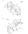
扉枠ベースユニット100の球送りユニット250について、主に図3及び図4を参照して詳細に説明する。図3(a)は扉枠ベースユニットの球送りユニットを前から見た斜視図であり、(b)は球送りユニットを後ろから見た斜視図である。図4(a)は球送りユニットを分解して前から見た分解斜視図であり、(b)は球送りユニットの後ケースと不正防止部材を外して後から見た分解斜視図である。球送りユニット250は、皿ユニット320の上皿321から供給される遊技球を一つずつ球発射装置650へ供給することができると共に、上皿321内に貯留された遊技球を、上皿球抜きボタン327の操作によって下皿へ抜くことができるものである。
[Ball feed unit]
The ball feeding unit 250 of the door frame base unit 100 will be described in detail mainly with reference to FIGS. FIG. 3A is a perspective view of the ball feed unit of the door frame base unit as seen from the front, and FIG. 3B is a perspective view of the ball feed unit as seen from the back. FIG. 4A is an exploded perspective view of the ball feeding unit as seen from the front, and FIG. 4B is an exploded perspective view of the ball feeding unit as seen from the rear after removing the rear case and the fraud prevention member. The ball feeding unit 250 can supply the game balls supplied from the upper plate 321 of the plate unit 320 to the ball launching device 650 one by one, and the game balls stored in the upper plate 321 are supplied to the upper plate ball. It can be pulled out to the lower pan by operating the pull button 327.
球送りユニット250は、皿ユニット320の上皿321に貯留された遊技球が、皿ユニットベース323の上皿球送り口323d、扉枠ベース110の球送り開口115を通して供給され前後方向に貫通した進入口251a、及び進入口251aの下側に開口する球抜口251bを有し後方が開放された箱状の前カバー251と、前カバー251の後端を閉鎖すると共に前方が開放された箱状で、前後方向に貫通し前カバー251の進入口251aから進入した遊技球を球発射装置650へ供給するための打球供給口252aを有した後カバー252と、後カバー252及び前カバー251の間で前後方向へ延びた軸周りに回動可能に軸支され前カバー251の後側で進入口251aと球抜口251bとの間を仕切る仕切部253aを有した球抜き部材253と、球抜き部材253の仕切部253a上の遊技球を一つずつ後カバー252の打球供給口252aへ送り前カバー251と後カバー252との間で上下方向へ延びた軸周りに回動可能に支持された球送り部材254と、球送り部材254を回動させる球送ソレノイド255と、を備えている。
In the ball feed unit 250, the game balls stored in the upper plate 321 of the plate unit 320 are supplied through the upper plate ball feed port 323d of the plate unit base 323 and the ball feed opening 115 of the door frame base 110 and penetrated in the front-rear direction. A box-shaped front cover 251 that has an entrance 251a and a ball outlet 251b that opens to the lower side of the entrance 251a and that is open at the rear, and a box that closes the rear end of the front cover 251 and is opened at the front A rear cover 252 having a striking ball supply port 252a for supplying a game ball that has penetrated in the front-rear direction and entered from the entrance 251a of the front cover 251 to the ball launcher 650, and the rear cover 252 and the front cover 251 And a partition portion 253a that is pivotally supported around a shaft extending in the front-rear direction and partitions the entrance 251a and the ball outlet 251b on the rear side of the front cover 251. The ball punching member 253 and the game balls on the partitioning portion 253a of the ball punching member 253 are sent one by one to the hitting ball supply port 252a of the rear cover 252, and around the axis extending in the vertical direction between the front cover 251 and the rear cover 252 And a ball feed member 254 that is rotatably supported, and a ball feed solenoid 255 that rotates the ball feed member 254.
この球送りユニット250は、図示するように、正面視で、球送り部材254が進入口251aの右側に配置されており、球送り部材254の左側に球抜き部材253が、球送り部材254の右側に球送ソレノイド255が夫々配置されている。
As shown in the figure, the ball feeding unit 250 has a ball feeding member 254 disposed on the right side of the entrance 251a in front view, and a ball removing member 253 on the left side of the ball feeding member 254. A ball feeding solenoid 255 is arranged on the right side.
球送りユニット250の前カバー251は、正面視で球抜口251bの左側に、球抜き部材253の回転中心に対して同心円状に形成された円弧状のスリット251cを備えており、このスリット251cから後述する球抜き部材253の作動棹253cが前方へ延びだすようになっている。また、前カバー251は、進入口251aの上縁から上側が上方へ延びだしており、扉枠3を組立てた際に、皿ユニットベース323の球送り誘導路323e及び球抜き誘導路323fの上流端側の後方へ開放されている部位を後側から閉鎖するように形成されている。
The front cover 251 of the ball feeding unit 250 includes an arc-shaped slit 251c concentrically formed with respect to the rotation center of the ball removing member 253 on the left side of the ball outlet 251b when viewed from the front, and this slit 251c. An operating rod 253c of a ball punching member 253, which will be described later, extends forward. The front cover 251 extends upward from the upper edge of the entrance 251a. When the door frame 3 is assembled, the front cover 251 is located upstream of the ball feed guide path 323e and the ball removal guide path 323f of the dish unit base 323. The part opened to the rear on the end side is formed to be closed from the rear side.
球抜き部材253は、進入口251aよりも下側で進入口251aと球抜口251bとの間を仕切り上面が球送り部材254の方向へ向かって低くなる仕切部253aと、仕切部253aの球送り部材254とは反対側の端部から下方へ延出すると共に上下方向の中間付近から球抜口251bの下側中央へ向かってく字状に屈曲し下端が前後方向へ延びた軸周りに回動可能に支持される回動棹部253bと、回動棹部253bの上端から前方へ向かって突出する棒状の作動棹253cと、作動棹253cよりも下側で回動棹部253bの側面から仕切部253aとは反対側へ突出した錘部253dと、を備えている。球抜き部材253の作動棹253cは、前カバー251に形成された円弧状のスリット251cを通して前方へ突出するように形成されている(図3(a)を参照)。作動棹253cは、扉枠ベース110の球送り開口115を介して皿ユニット320の上皿球抜きボタン327の押圧操作によって動作する作動伝達部327aの上端と当接する。
The ball removal member 253 includes a partition portion 253a that is divided below the entrance port 251a and between the entrance port 251a and the ball exit port 251b and whose upper surface is lowered toward the ball feed member 254, and a ball of the partition portion 253a. It extends downward from the end opposite to the feed member 254 and bends in the shape of a letter from the middle in the vertical direction toward the lower center of the ball outlet 251b and rotates around the axis whose lower end extends in the front-rear direction. A pivot collar 253b that is movably supported, a rod-shaped actuation collar 253c that protrudes forward from the upper end of the pivot collar 253b, and a side below the actuation collar 253c from the side surface of the pivot collar 253b. A weight portion 253d protruding to the opposite side of the partition portion 253a. The operating rod 253c of the ball removing member 253 is formed so as to protrude forward through an arc-shaped slit 251c formed in the front cover 251 (see FIG. 3A). The operating rod 253 c comes into contact with the upper end of the operation transmitting portion 327 a that is operated by the pressing operation of the upper dish ball removal button 327 of the dish unit 320 through the ball feed opening 115 of the door frame base 110.
球送り部材254は、進入口251a及び球抜き部材253の仕切部253aの方を向き上下方向へ延びた回転軸芯を中心とした平面視が扇状の遮断部254aと、遮断部254aの後端から回転軸芯側へ円弧状に窪んだ球保持部254bと、球保持部254bの後端から下方へ延出する棒状の棹部254cと、を備えている。球送り部材254における遮断部254aと球保持部254bは、夫々回転軸芯を中心とした約90゜の角度範囲内に夫々形成されている。また、球送り部材254の球保持部254bは、一つの遊技球を保持可能な大きさとされている。球送り部材254は、球送ソレノイド255の駆動によって回転軸芯と偏芯した位置に配置された棹部254cが左右方向へ移動させられることで、回転軸芯周りに回動する。
The ball feeding member 254 has a fan-shaped blocking portion 254a and a rear end of the blocking portion 254a in plan view with the rotation axis extending in the vertical direction facing the entrance 251a and the partitioning portion 253a of the ball removing member 253. A sphere holding portion 254b that is recessed in an arc shape from the rotation axis to the rotation shaft core side, and a rod-like flange portion 254c that extends downward from the rear end of the sphere holding portion 254b. The blocking portion 254a and the ball holding portion 254b of the ball feeding member 254 are each formed within an angle range of about 90 ° around the rotation axis. Further, the ball holding portion 254b of the ball feeding member 254 has a size that can hold one game ball. The ball feeding member 254 rotates around the rotation axis when the collar portion 254c arranged at a position eccentric from the rotation axis is moved in the left-right direction by driving the ball feeding solenoid 255.
この球送り部材254は、遮断部254aが仕切部253aの方向を向くと同時に球保持部254bが打球供給口252aと連通した方向を向いた供給位置と、球保持部254bが仕切部253aの方向へ向いた保持位置との間で回動するようになっている。球送り部材254が供給位置の時には、球保持部254bに保持された遊技球が、打球供給口252aから球発射装置650へ供給されると共に、進入口251aから仕切部253a上に進入した遊技球が、遮断部254aによって球保持部254b(打球供給口252a)側への移動が遮断されて仕切部253a上に留まった状態となる。一方、球送り部材254が保持位置へ回動すると、球保持部254bが仕切部253aの方向を向くと共に、球保持部254bの棹部254c側の端部が打球供給口252aを閉鎖した状態となり、仕切部253a上の遊技球が一つだけ球保持部254b内に保持される。
The ball feeding member 254 includes a supply position in which the blocking portion 254a faces the direction of the partition portion 253a and at the same time the ball holding portion 254b communicates with the hitting ball supply port 252a, and the ball holding portion 254b faces the direction of the partition portion 253a. It is designed to rotate between the holding position facing toward. When the ball feeding member 254 is in the supply position, the game ball held by the ball holding portion 254b is supplied from the hit ball supply port 252a to the ball launching device 650 and enters the partition portion 253a from the entrance 251a. However, the blocking unit 254a blocks the movement toward the ball holding unit 254b (hitting ball supply port 252a) and stays on the partition unit 253a. On the other hand, when the ball feed member 254 rotates to the holding position, the ball holding portion 254b faces the partition portion 253a, and the end of the ball holding portion 254b on the flange 254c side closes the hitting ball supply port 252a. Only one game ball on the partition portion 253a is held in the ball holding portion 254b.
また、球送りユニット250は、球送ソレノイド255の駆動(通電)によって先端が上下方向へ揺動する球送り作動桿256と、球送り作動桿256における上下方向へ揺動する先端の動きによって前後方向へ延びた軸周りに回動すると共に、球送り部材254を上下方向へ延びた軸周りに回動させる球送りクランク257と、を備えている。球送りクランク257は、球送り作動桿256の上下動する先端と係合可能とされ左右方向へ延びた係合部257aと、係合部257aの球送り作動桿256と係合する側とは反対側に配置され前カバー251と後カバー252との間で前後方向へ延びた軸周りに回動可能に軸支される軸部257bと、軸部257bから上方へ延出し球送り部材254における回動中心に対して偏芯した位置から下方へ突出する棒状の棹部254c(図4(b)を参照)と係合する伝達部257cと、を備えている。
Further, the ball feed unit 250 is moved back and forth by the ball feed operation rod 256 whose tip is swung vertically by driving (energizing) the ball feed solenoid 255 and the movement of the tip of the ball feed operation rod 256 swinging vertically. And a ball feed crank 257 that rotates around an axis extending in the direction and rotates the ball feed member 254 around an axis extending in the vertical direction. The ball feed crank 257 is engageable with the tip of the ball feed actuating rod 256 that moves up and down and extends in the left-right direction, and the side that engages the ball feed actuating rod 256 of the engaging portion 257a. A shaft portion 257b that is disposed on the opposite side and is pivotally supported around an axis extending in the front-rear direction between the front cover 251 and the rear cover 252; and a ball feed member 254 that extends upward from the shaft portion 257b. A transmission portion 257c that engages with a rod-shaped flange portion 254c (see FIG. 4B) that protrudes downward from a position that is eccentric with respect to the rotation center is provided.
この球送りユニット250は、球送り作動桿256及び球送りクランク257によって、上下方向へ進退する球送ソレノイド255の駆動により揺動する球送り作動桿256の動きを伝達させて球送り部材254を回動させることができる。なお、球送ソレノイド255の非駆動時(通常時)では、球送り作動桿256が球送ソレノイド255の下端から離れて揺動する先端が下方へ位置した状態となり、この状態では球送り部材254が供給位置に位置した状態となる。また、球送ソレノイド255の駆動時では、球送り作動桿256が球送ソレノイド255の下端に吸引されて揺動する先端が上方へ位置した状態となり、球送り部材254が保持位置へ回動する。つまり、球送ソレノイド255が駆動される(ONの状態)と、球送り部材254が遊技球を一つ受入れ、球送ソレノイド255の駆動が解除される(OFFの状態)と、球送り部材254が受入れた遊技球を球発射装置650側の発射レール684の発射位置へ送る(供給する)ことができる。この球送りユニット250における球送ソレノイド255の駆動は、払出制御基板の発射制御部(図示は省略)により発射ソレノイド654の駆動制御と同期して制御される。
The ball feed unit 250 transmits the movement of the ball feed actuating rod 256 that is swung by driving the ball feed solenoid 255 that moves forward and backward by the ball feed actuating rod 256 and the ball feed crank 257 so that the ball feed member 254 is moved. It can be rotated. When the ball feed solenoid 255 is not driven (normal time), the ball feed operating rod 256 is in a state where the tip of the ball feed solenoid 256 swinging away from the lower end of the ball feed solenoid 255 is positioned downward. In this state, the ball feed member 254 is moved downward. Is located at the supply position. Further, when the ball feeding solenoid 255 is driven, the ball feeding operation rod 256 is attracted to the lower end of the ball feeding solenoid 255 and the tip of the swing is positioned upward, and the ball feeding member 254 rotates to the holding position. . That is, when the ball feeding solenoid 255 is driven (ON state), the ball feeding member 254 receives one game ball, and when the ball feeding solenoid 255 is released (OFF state), the ball feeding member 254 is activated. Can be sent (supplied) to the launch position of the launch rail 684 on the ball launcher 650 side. The driving of the ball feeding solenoid 255 in the ball feeding unit 250 is controlled in synchronization with the driving control of the firing solenoid 654 by a firing control unit (not shown) of the payout control board.
また、球送りユニット250における回動可能に軸支された球抜き部材253は、錘部253cによって正面視反時計周りの方向へ回転するようなモーメントがかかるようになっているが、前方へ突出した作動棹253cが皿ユニット320の上皿球抜きボタン327の押圧操作によって動作する作動伝達部327aの上端と当接することで、その回動が規制されるため、通常時では、球抜き部材253の仕切部253aが進入口251aと球抜口251bとの間を仕切っており、球抜口251b側へ遊技球が侵入することはない。
Further, the ball removing member 253 pivotally supported in the ball feeding unit 250 is applied with a moment that rotates counterclockwise by the weight portion 253c, but protrudes forward. Since the rotation of the actuating rod 253c is brought into contact with the upper end of the operation transmitting portion 327a that is operated by the pressing operation of the upper dish ball removal button 327 of the dish unit 320, the ball removal member 253 is normally operated. The partition 253a partitions the entrance 251a and the ball outlet 251b, so that the game ball does not enter the ball outlet 251b side.
そして、遊技者が、皿ユニット320の上皿球抜きボタン327を下方へ押圧操作すると、図示しない上皿球抜きスライダが作動伝達部327aと共に下方へスライドして、作動伝達部327aの下方への移動に伴って作動棹253cも相対的に下方へ移動することとなる。作動伝達部327aと共に作動棹253cが下方へ移動すること、球抜き部材253が正面視反時計周りの方向へ回動し、仕切部253aによる進入口251aと球抜口251bとの間の仕切りが解除される。これにより、進入口251aから進入した遊技球が、球抜口251bから皿ユニット320の球抜き誘導路323fへと排出され、下皿球供給口323cを介して下皿322へ排出(供給)させることができる。
Then, when the player presses the upper dish ball removal button 327 of the dish unit 320 downward, an upper dish ball removal slider (not shown) slides downward together with the operation transmission unit 327a, and moves downward to the operation transmission unit 327a. With the movement, the operating rod 253c also moves relatively downward. The operating rod 253c moves downward together with the operation transmitting portion 327a, the ball removing member 253 rotates counterclockwise when viewed from the front, and the partition between the entrance 251a and the ball outlet 251b by the partition 253a Canceled. As a result, the game ball that has entered from the entrance 251a is discharged from the ball outlet 251b to the ball outlet guide path 323f of the tray unit 320 and discharged (supplied) to the lower tray 322 via the lower tray ball supply port 323c. be able to.
なお、球抜き部材253の作動棹253cが当接する作動伝達部327aが形成されている上皿球抜きスライダは、上皿球抜きバネによって上方へ付勢されているので、仕切部253a上に遊技球が勢い良く供給されても、その衝撃を、作動棹253cを介して上皿球抜きバネによって吸収させることができ、球抜き部材253等が破損するのを防止することができると共に、遊技球が仕切部253aで跳ね返るのを防止することができる。
The upper dish ball removal slider formed with the action transmitting portion 327a with which the operation rod 253c of the ball removal member 253 contacts is urged upward by the upper dish ball removal spring, so that the game is placed on the partition portion 253a. Even if the ball is supplied vigorously, the impact can be absorbed by the upper plate ball removing spring via the operating rod 253c, and the ball removing member 253 and the like can be prevented from being damaged, and the game ball Can be prevented from bouncing back at the partition portion 253a.
また、球送りユニット250は、後カバー252における打球供給口252aの背面視で右上に前方へ窪んだ矩形状の取付凹部252b(図4(b)等を参照)が形成されていると共に、その取付凹部252b内に第1の不正防止手段たる操作線無効化部材260が収容されるように取付けられている。球送りユニット250の操作線無効化部材260は、工具鋼やステンレス等の硬質の金属板により形成されており、後カバー252の取付凹部252a内に対して後側から脱着可能に取付けられている。なお、ここで、操作線の無効化とは、操作線を切断又は挟止(挟んで止める)又は絡める(巻き取る)又はホットメルト等で接着する等して不正球の操作が正常に行えない状態にすることをいう。
In addition, the ball feeding unit 250 has a rectangular mounting recess 252b (see FIG. 4B, etc.) that is recessed to the upper right in the rear view of the hitting ball supply port 252a in the rear cover 252. It is attached so that the operation line invalidating member 260 as the first fraud prevention means is accommodated in the attachment recess 252b. The operation line invalidating member 260 of the ball feeding unit 250 is formed of a hard metal plate such as tool steel or stainless steel, and is attached to the inside of the mounting recess 252a of the rear cover 252 so as to be detachable from the rear side. . Here, the invalidation of the operation line means that the operation line cannot be normally operated by cutting, pinching (pinching), entanglement (winding), or bonding with hot melt or the like. It means making it into a state.
[第1の不正防止手段(操作線無効化部材)]
操作線無効化部材260は、正面視の外形が左右に延びた長方形状に形成されており、右辺から左方へ所定距離の間において、上下方向略中央で上下に分離している第一片部261及び第二片部262と、第一片部261及び第二片部262の互いに対向している辺の先端側(正面視右端側)でC面取り状に夫々形成されている傾斜部263と、を備えている。操作線無効化部材260の第一片部261は、操作線無効化部材260の平板面に対して、図4(a)において正面視右端が後方へ突出するように屈曲させられている。一方、第二片部262は、操作線無効化部材260の平板面と同一面上に延びている。これにより、平面視において、第一片部261と第二片部262とによって、右方に向かうに従ってV字状に広がる剪断部260vを形成している。
[First fraud prevention means (operation line invalidating member)]
The operation line invalidating member 260 is formed in a rectangular shape whose outer shape in front view extends to the left and right, and is a first piece that is vertically separated at the approximate center in the vertical direction within a predetermined distance from the right side to the left. The inclined portion 263 formed in a C-chamfered shape on the distal end side (right end side in the front view) of the side facing each other of the portion 261 and the second piece portion 262, and the first piece portion 261 and the second piece portion 262, respectively. And. The first piece 261 of the operation line invalidating member 260 is bent with respect to the flat surface of the operation line invalidating member 260 so that the right end in front view protrudes rearward in FIG. On the other hand, the second piece 262 extends on the same plane as the flat surface of the operation line invalidating member 260. Thus, in plan view, the first piece 261 and the second piece 262 form a shearing portion 260v that expands in a V shape toward the right.
操作線無効化部材260は、後カバー252の取付凹部252bに取付けられることで、第一片部261と第二片部262とで形成されるV字状の剪断部260vが打球供給口252a内と連通した状態となる。
The operation line invalidating member 260 is attached to the attachment recess 252b of the rear cover 252 so that the V-shaped shearing portion 260v formed by the first piece 261 and the second piece 262 is within the hitting ball supply port 252a. It will be in the state connected with.
この操作線無効化部材260によれば、柔軟な紐状の操作線(糸、ピアノ線、ワイヤーあるいはカテーテル等の線状部材)を取付けた不正球(遊技球か又はそれとほぼ同径の球)を、上皿321から球送りユニット250を介して球発射装置680により遊技領域5a内に打込み、不正球に取付けられた上皿321側に出ている操作線を操作して、不正球を用いて不正な球流路を形成したり、不正球を第一始動口等に出し入れさせるような不正行為が行われる際に、球発射装置680により発射(打球)された不正球の勢いによって、不正球に取付けられた操作線を、第一片部261と第二片部262との間に挿入させた上で、第一片部261と第二片部262とによって形成された剪断部260vの狭くなった部位によりハサミのごとくに切断させることができ、そうして操作線を無効化して不正球を用いた不正行為が行われるのを抑止することができる。なお、球送りユニット250に設けられる第1の不正防止手段としては、上記した形態のものに限らず、他の形態であってもよい。例えば、不正球に取付けられた操作線を切断或は狭止して、不正行為を抑止する構成であれば、金属板を上述と異なる形態に屈曲させたり、折り曲げた操作線無効化部材260を設ける構成としてもよいし、不正球に取付けられた操作線を切断或は狭止し得る形状を有した樹脂成型部材を、金属板に代えて設ける構成としてもよい。
According to the operation line invalidating member 260, an illegal ball (a game ball or a ball having the same diameter as the game ball) having a flexible string-like operation line (a linear member such as a thread, a piano wire, a wire, or a catheter) attached thereto. Is cast into the game area 5a by the ball launcher 680 from the upper plate 321 via the ball feeding unit 250, and an operation line extending to the upper plate 321 attached to the illegal ball is operated to use the illegal ball. When a fraudulent act is performed, such as forming an illegal ball flow path or causing an illegal ball to be taken in or out of the first starting port, etc., fraud is caused by the momentum of the illegal ball launched (ball hit) by the ball launcher 680. The operation line attached to the sphere is inserted between the first piece 261 and the second piece 262, and then the shearing portion 260v formed by the first piece 261 and the second piece 262 is inserted. Scissors due to the narrowed part Can be cross, it is possible to suppress the fraud using a fraud sphere takes place thus invalidates the operating line. Note that the first fraud prevention means provided in the ball feeding unit 250 is not limited to the above-described form, but may be another form. For example, if the operation line attached to the illegal sphere is cut or narrowed to prevent illegal acts, the operation line invalidating member 260 may be bent or bent in a form different from the above. It is good also as a structure provided, and it is good also as a structure which replaces with a metal plate and has the resin molding member which has the shape which can cut | disconnect or narrow the operation line attached to the illegal ball.
[ファールカバーユニット]
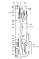
扉枠ベースユニット100のファールカバーユニット270について、図5乃至図8を参照して詳細に説明する。図5(a)は扉枠ベースユニットのファールカバーユニットを前から見た斜視図であり、(b)はファールカバーユニットを後ろから見た斜視図である。また、図6(a)はファールカバーユニットを蓋部材を外して前から見た分解斜視図であり、(b)はファールカバーユニットを蓋部材を外して後ろから見た分解斜視図である。更に、図7は、図6(a)のX−X線断面図、図8は、一部拡大図を含む図7のY−Y線断面図である。
[Foul cover unit]
The foul cover unit 270 of the door frame base unit 100 will be described in detail with reference to FIGS. FIG. 5A is a perspective view of the door cover base unit as viewed from the front of the foul cover unit, and FIG. 5B is a perspective view of the foul cover unit as viewed from the rear. FIG. 6A is an exploded perspective view of the foul cover unit viewed from the front with the lid member removed, and FIG. 6B is an exploded perspective view of the foul cover unit viewed from the rear with the lid member removed. 7 is a cross-sectional view taken along line XX of FIG. 6A, and FIG. 8 is a cross-sectional view taken along line YY of FIG. 7 including a partially enlarged view.
ファールカバーユニット270は、図示するように、扉枠ベース110の後側に取付けられ前側が開放された浅い箱状のユニット本体271と、ユニット本体271の前面に取付けられている平板状の蓋部材272と、を備えている。ファールカバーユニット270は、正面視左上隅において前後に貫通しており本体枠4の下部満タン球経路ユニット860の通常誘導路と皿ユニット320の球用開口である上皿球供給口323aとを連通させる貫通球通路273と、貫通球通路273の正面視右下側で後方へ向かって開口しており本体枠4の下部満タン球経路ユニット860の満タン誘導路と連通可能な満タン球受口274と、を備えている。
As shown in the figure, the foul cover unit 270 includes a shallow box-shaped unit main body 271 attached to the rear side of the door frame base 110 and opened on the front side, and a flat lid member attached to the front surface of the unit main body 271. 272. The foul cover unit 270 penetrates back and forth in the upper left corner when viewed from the front, and passes through the normal guide path of the lower full ball path unit 860 of the main body frame 4 and the upper dish ball supply port 323a which is a ball opening of the dish unit 320. A penetrating sphere passage 273 to be communicated, and a full sphere that opens rearward on the lower right side in front view of the penetrating sphere passage 273 and can communicate with the full filling guide path of the lower full sphere passage unit 860 of the main body frame 4. Receiving opening 274.
また、ファールカバーユニット270は、満タン球受口274の正面視右側で上方へ向かって開口しており本体枠4の球発射装置680により発射されたにも関わらず遊技領域5a内へ到達しなかった遊技球(発射レール684と外レール1001の間に形成されたファール球落下口1013に落下したファール球)を受けるファール球受部275と、正面視右下隅付近で前方へ向かって開口しており満タン球受口274及びファール球受部275に受入れられた遊技球を前方へ放出すると共に皿ユニット320の球用開口たる下皿球供給口323cと連通する球放出口276と、該球放出口276(厳密には後述する貯留通路277)と前記ファール球受部275とをつなぐ連絡通路2751と、を備えている。この連絡通路2751は、ファール球受部275の底壁2750の下側に該底壁2750とは逆の勾配にして配設された上部通路壁2752と、該上部通路壁2752から遊技球ほぼ1個分の間隔を離して平行に配設された下部通路壁2753とからなり、始端部がファール球受部275の底壁2750の下傾端部に上向きに開口し、終端部が貯留通路277に対して下向きに開口する。
なお、発射レール684と外レール1001の間に開設されたファール球落下口1013からファール球受部275と連絡通路2751と貯留通路277を通って球放出口276に至る一連の通路がファール球返却通路であり、これら一連の要素によって返却通路部1014が形成される。
In addition, the foul cover unit 270 opens upward on the right side of the full ball receiving port 274 when viewed from the front, and reaches the game area 5a despite being fired by the ball launcher 680 of the main body frame 4. A foul ball receiving portion 275 that receives a game ball that has not been played (a foul ball that has fallen to the foul ball dropping port 1013 formed between the launch rail 684 and the outer rail 1001) and a front opening in the vicinity of the lower right corner in front view. A ball discharge port 276 that discharges the game balls received in the full tank reception port 274 and the foul ball reception unit 275 to the front and communicates with the lower plate ball supply port 323c serving as a ball opening of the plate unit 320; A ball discharge port 276 (strictly speaking, a storage passage 277 described later) and a communication passage 2751 that connects the foul ball receiver 275 are provided. The communication passage 2751 includes an upper passage wall 2752 disposed below the bottom wall 2750 of the foul ball receiving portion 275 with a slope opposite to the bottom wall 2750, and approximately 1 game ball from the upper passage wall 2752. And a lower passage wall 2753 arranged in parallel at a distance from each other. A start end portion opens upward at a lower inclined end portion of the bottom wall 2750 of the foul ball receiving portion 275 and a terminal end portion is a storage passage 277. Open downward.
A series of passages from the foul ball drop opening 1013 established between the launch rail 684 and the outer rail 1001 to the ball discharge port 276 through the foul ball receiving portion 275, the communication passage 2751 and the storage passage 277 are returned to the foul ball. A return passage portion 1014 is formed by a series of elements.
更に、ファールカバーユニット270は、ユニット本体271及び蓋部材272によって、満タン球受口274及びファール球受部275と球放出口276との間に形成されており所定量の遊技球を貯留可能な広さを有している貯留通路277と、貯留通路277の内壁の一部を構成しており下端が回動可能にユニット本体271に取付けられている平板状の可動片278と、可動片278の貯留通路277から遠ざかる方向への回動を検知する満タン検知センサ279と、可動片278を貯留通路277の中心側へ付勢しているバネ280と、を備えている。
Further, the foul cover unit 270 is formed between the full tank receiving port 274 and the foul ball receiving unit 275 and the ball discharge port 276 by the unit main body 271 and the lid member 272, and can store a predetermined amount of game balls. A storage passage 277 having a wide area, a plate-shaped movable piece 278 constituting a part of the inner wall of the storage passage 277 and having a lower end rotatably attached to the unit main body 271, and a movable piece A full tank detection sensor 279 that detects rotation of the 278 in a direction away from the storage passage 277 and a spring 280 that biases the movable piece 278 toward the center of the storage passage 277 are provided.
このファールカバーユニット270は、皿ユニット320の下皿322内が遊技球で一杯になって、球放出口276から遊技球が下皿322側へ放出されなくなると、貯留通路277内にある程度の数の遊技球を貯留することができる。そして、貯留通路277内にある程度の数の遊技球が貯留されると、遊技球の重さによって可動片278の上端がバネ280の付勢力に抗して貯留通路277から遠ざかる方向へ移動するように可動片278が回動し、その回動が満タン検知センサ279によって検知される。これにより、下皿322が遊技球で満タンになっていると判断することができるため、満タン検知センサ279により満タンが検知されると、これ以上の遊技球の払出しを停止させると共に、その旨を遊技者や遊技ホールの係員等に報知して、下皿322の満タンを解消させるように促すことができる。
When the inside of the lower plate 322 of the dish unit 320 is filled with game balls and the game balls are not released from the ball discharge port 276 to the lower plate 322 side, the foul cover unit 270 has a certain number in the storage passage 277. The game balls can be stored. When a certain number of game balls are stored in the storage passage 277, the upper end of the movable piece 278 moves away from the storage passage 277 against the biasing force of the spring 280 by the weight of the game balls. The movable piece 278 rotates, and the rotation is detected by the full tank detection sensor 279. Thereby, since it can be determined that the lower tray 322 is full of game balls, when full tank detection is detected by the full tank detection sensor 279, payout of further game balls is stopped, This can be notified to a player, a staff member of the game hall, or the like, and can be urged to eliminate the filling of the lower plate 322.
また、ファールカバーユニット270は、ユニット本体271の後側で貫通球通路273の下側に取付けられており、本体枠4の後述する払出ユニット800における下部満タン球経路ユニット860の誘導路開閉扉863の作動突部863eが当接可能な扉開閉当接部281を備えている(図108を参照)。扉開閉当接部281は、後面が下方へ向かうに従って前方へ移動するように傾斜している。この扉開閉当接部281は、本体枠4に対して扉枠3を閉じると、誘導路扉部材863の作動突部863eが当接するように形成されている。この扉開閉当接部281に誘導路開閉部863の作動突部863eが当接することで、誘導路扉部材863が回動して通常誘導路及び満タン誘導路の下流端(前側開口)を開放させることができる。
The foul cover unit 270 is attached to the rear side of the unit main body 271 and below the through ball passage 273, and the guide path opening / closing door of the lower full ball path unit 860 in the payout unit 800 described later of the main body frame 4. A door opening / closing contact portion 281 with which the operation protrusion 863e of 863 can contact is provided (see FIG. 108). The door opening / closing contact portion 281 is inclined so that the rear surface moves forward as it goes downward. The door opening / closing contact portion 281 is formed such that when the door frame 3 is closed with respect to the main body frame 4, the operation protrusion 863 e of the guideway door member 863 contacts. When the operating protrusion 863e of the guideway opening / closing part 863 comes into contact with the door opening / closing contact part 281, the guideway door member 863 rotates and the downstream end (front opening) of the normal guideway and the full tank guideway is moved. It can be opened.
また、ファールカバーユニット270には、前記操作線Lを取付けた不正球Qによる不正を抑止するための第2の不正防止手段たる操作線無効化部材2600が設けられ、同じく前記発射レール684と外レール1001の間に開設されたファール球落下口1013には第3の不正防止手段たる操作線無効化部材2600H,2600Sが設けられている。
Further, the foul cover unit 270 is provided with an operation line invalidating member 2600 as a second fraud prevention means for suppressing fraud due to the illegal ball Q to which the operation line L is attached. The foul ball dropping opening 1013 opened between the rails 1001 is provided with operation line invalidating members 2600H and 2600S as third fraud prevention means.
[第2の不正防止手段(操作線無効化部材)]
ファールカバーユニット270に設けられた第2の操作線無効化部材2600は、連絡通路2751の上部通路壁2752とファール球受部275の底壁2750との間の内部空間であって、図8拡大図に示したようにユニット本体271の取付孔271h及び蓋部材272の取付孔272hに両横の凸部2601が嵌合支持され且つ上部通路壁2752の上面に固着(接着)して取り付けられ、さらに、安全上の配慮から従業員や遊技機組立作業員等の手が接触困難なように、ユニット本体271及び蓋部材272によって外部からカバーして収容されている。
具体的な操作線無効化部材2600は、前記球送りユニット250に設けられた前記操作線無効化部材260と同等の構成要素を備えており、図4の屈曲した第一片部261に相当する第一片部2610と、真っ直ぐな第二片部262に相当する前記凸部2601から延設された第二片部2620とによって、連絡通路2751の球の流下方向と対向する向きに開口するV字状の剪断部2600vが形成されている。
なお、実施形態のファールカバーユニット270は、図8拡大図に示したように、操作線無効化部材2600の前記V字状の剪断部2600vの中心が、ファールカバーユニット270を構成する蓋部材272の内面とほぼ面一になるように配設されると共にファール球受部275の底壁2750と連絡通路2751の上部通路壁2752との折り返し部分に操作線無効化部材2600の剪断部2600vに向けて操作線Lを誘導し得るテーパ状の誘導部2754が設けられている。具体的にはファール球受部275の底壁2750は、その上面を遊技球が流下するに必要な面幅を有しつつ、上部通路壁2752との折り返し部分に、蓋部材272側に向けて操作線無効化部材2600側に下る第一の傾斜部2754aと、その第一の傾斜部2754aに連続するように蓋部材272沿いに操作線無効化部材2600の剪断部2600vに向かって幅が狭くなる先窄み形状(操作線Lを捕獲し得る形状)の第二の傾斜部2754bと、からなるテーパ状の誘導部2754を有している。そして、この誘導部2754に不正球Qの転がりや外部からの引張りで張力を受けた操作線Lが巻回状に摺接すると、操作線Lに加わる張力によって前記第一の傾斜部2754aから第二の傾斜部2754bを滑るようにして該操作線Lが操作線無効化部材2600に誘導される。これにより、操作線Lを操作線無効化部材2600で確実に捉えることができる。このようにして正常なファール球の円滑な流下と、不正球Qに取り付けられた操作線Lの誘導を担っている。なお、操作線Lをより捕獲しやすくするために、誘導部2754の第一の傾斜部2754aと第二の傾斜部2754bの角部を湾曲状に形成しておくようにしてもよい。
[Second fraud prevention means (operation line invalidating member)]
The second operation line disabling member 2600 provided in the foul cover unit 270 is an internal space between the upper passage wall 2752 of the communication passage 2751 and the bottom wall 2750 of the foul ball receiving portion 275. As shown in the figure, both lateral projections 2601 are fitted and supported in the mounting holes 271h of the unit main body 271 and the mounting holes 272h of the lid member 272, and are attached to the upper surface of the upper passage wall 2752 by being fixed (adhered). Further, for safety reasons, the unit main body 271 and the lid member 272 are externally covered and accommodated so that the hands of employees, gaming machine assembly workers, and the like are difficult to contact.
A specific operation line invalidating member 2600 includes the same components as the operation line invalidating member 260 provided in the ball feeding unit 250, and corresponds to the bent first piece 261 in FIG. The first piece 2610 and the second piece 2620 extended from the convex portion 2601 corresponding to the straight second piece 262 open V in a direction opposite to the flow direction of the sphere of the communication passage 2751. A character-shaped shearing portion 2600v is formed.
In the foul cover unit 270 of the embodiment, as shown in the enlarged view of FIG. 8, the center of the V-shaped shearing portion 2600v of the operation line invalidating member 2600 is the lid member 272 constituting the foul cover unit 270. Are arranged so as to be substantially flush with the inner surface of the flaw ball receiving portion 275 and the folded portion of the bottom wall 2750 of the foul ball receiving portion 275 and the upper passage wall 2752 of the communication passage 2751 toward the shearing portion 2600v of the operation line invalidating member 2600. A tapered guiding portion 2754 capable of guiding the operation line L is provided. Specifically, the bottom wall 2750 of the foul ball receiving portion 275 has a surface width necessary for the game ball to flow down on the upper surface thereof, and is directed to the lid member 272 side at the folded portion with the upper passage wall 2752. The first inclined portion 2754a descending to the operation line invalidating member 2600 side, and the width narrows toward the shearing portion 2600v of the operation line invalidating member 2600 along the lid member 272 so as to be continuous with the first inclined portion 2754a. A tapered portion 2754 having a tapered shape (a shape capable of capturing the operation line L) and a second inclined portion 2754b. Then, when the operation line L that receives tension by rolling of the illegal sphere Q or pulling from the outside is brought into sliding contact with the guide portion 2754, the first inclined portion 2754a is changed from the first inclined portion 2754a by the tension applied to the operation line L. The operation line L is guided to the operation line invalidating member 2600 so as to slide on the second inclined portion 2754b. Accordingly, the operation line L can be reliably captured by the operation line invalidating member 2600. In this way, it is responsible for the smooth flow of the normal foul sphere and the guidance of the operation line L attached to the illegal sphere Q. In order to make it easier to capture the operation line L, the corners of the first inclined portion 2754a and the second inclined portion 2754b of the guide portion 2754 may be formed in a curved shape.
ファールカバーユニット270に設けられた第2の操作線無効化部材2600は以上のように構成されているため、下皿球供給口323cから遊技領域5aに連通する空間を用いて、操作線Lを取付けた不正球Qを遊技領域5aに侵入させるとともに、下皿球供給口323c側に出ている操作線Lを操作して、不正球Qを用いて不正な球流路を形成したり、不正球Qを第一始動口等に出し入れさせるような不正行為を抑止することができる。
例えば、下皿球供給口323cからセル板等の専用工具を使って不正球Qを返却通路部1014に押し込んで逆流させて球発射装置680の発射位置に送り込むような不正行為(以下「不正行為A」という。)が行われた場合、不正球Qが連絡通路2751の上部通路壁2752とファール球受部275の底壁2750との折り返し部分を越えて発射レール684の発射位置に向かうと、それに引っ張られて(張力が負荷されて)操作線Lが同折り返し部分に沿ってUターン状に回り込む。そうすると操作線Lが、誘導部2754のテーパに沿って操作線無効化部材2600に案内され、第一片部2610と第二片部2620によるV字状の剪断部2600vに入り込んで最終的に切断され、結果的に操作線Lが操作できなくなるから不正球Qを用いた不正行為を抑止することが可能となる。
また、操作線Lに複数の不正球Qをつなげてそのうちの1つを打球供給口252aから発射位置に送り込み、それを意図的にファール球にして、球用開口である下皿球供給口323cからファール球となった不正球に繋げられた操作線Lを掴んで後続の不正球Qを遊技領域5aに発射する不正行為(以下「不正行為B」という。)が行われた場合にも、連絡通路2751の上部通路壁2752とファール球受部275の底壁2750との折り返し部分に存在する操作線Lが、後続の不正球Qの発射により引っ張られて(張力が負荷されて)操作線Lが同折り返し部分に押し付けられ、上記と同様に操作線Lが剪断部2600vに入り込んで切断され、結果的に操作線Lが操作できなくなるから不正球Qを用いた不正行為を抑止することが可能となる。なお、図7、図8は、不正行為Bが行われた場合を想定した説明図である。また、上記した不正行為Bに対しては、第1の不正防止手段たる操作線無効化部材260等がファール球となる不正球Qに十分に効果を発揮できない可能性(例えば、ファール球となる程度の強さで不正球Qが発射されても操作線Lが第1の不正防止手段で無効化されない可能性)もあるため、本実施形態は、第1の不正防止手段による不正対策を補強する効果も有している。このため、不正行為Bを対象にする場合には、第1、第2の不正防止手段たる操作線無効化部材260,2600、さらには後述する第3の不正防止手段たる操作線無効化部材2600H,2600Sを適宜併用することが好ましい。
Since the second operation line disabling member 2600 provided in the foul cover unit 270 is configured as described above, the operation line L is set using the space communicating from the lower tray ball supply port 323c to the game area 5a. The attached illegal ball Q is allowed to enter the game area 5a, and the operation line L that is exposed to the lower dish ball supply port 323c is operated to form an illegal ball flow path using the illegal ball Q. Unauthorized actions that cause the ball Q to be taken in and out of the first starting port or the like can be suppressed.
For example, a fraudulent act (hereinafter referred to as “fraud act” in which the illegal ball Q is pushed into the return passage portion 1014 by using a dedicated tool such as a cell plate from the lower tray ball supply port 323c and flows backward to the launch position of the ball launcher 680. A ”) is performed, and when the illegal ball Q goes over the folded portion of the upper passage wall 2752 of the communication passage 2751 and the bottom wall 2750 of the foul ball receiving portion 275 toward the firing position of the firing rail 684, When pulled (with tension applied), the operation line L wraps around the U-turn along the folded portion. Then, the operation line L is guided by the operation line invalidating member 2600 along the taper of the guide portion 2754, enters the V-shaped shearing portion 2600v by the first piece portion 2610 and the second piece portion 2620, and finally cuts. As a result, the operation line L cannot be operated, so that it is possible to suppress an illegal act using the illegal sphere Q.
In addition, a plurality of illegal balls Q are connected to the operation line L, and one of them is sent from the hitting ball supply port 252a to the launch position, which is intentionally made into a foul ball, and a lower dish ball supply port 323c which is a ball opening. Even when a fraudulent act (hereinafter referred to as “fraud act B”) is performed in which the operation line L connected to the fraudulent ball that has become a foul ball is grabbed and the subsequent fraudulent ball Q is launched into the game area 5a. The operation line L present at the folded portion between the upper passage wall 2752 of the communication passage 2751 and the bottom wall 2750 of the foul ball receiving portion 275 is pulled by the subsequent launch of the illegal ball Q (tension is applied), and the operation line L is pressed against the folded portion, and the operation line L enters the shearing portion 2600v and is cut in the same manner as described above. As a result, the operation line L cannot be operated. Possible It made. 7 and 8 are explanatory diagrams assuming a case where an illegal act B is performed. In addition, for the above-mentioned fraudulent act B, there is a possibility that the operation line invalidating member 260 or the like as the first fraud prevention means cannot sufficiently exert an effect on the illegal sphere Q that becomes a foul sphere (for example, a foul sphere is obtained) In this embodiment, there is a possibility that the operation line L is not invalidated by the first fraud prevention means even if the fraudulent sphere Q is launched with a certain degree of strength. Therefore, this embodiment reinforces the fraud countermeasures by the first fraud prevention means. It also has the effect of For this reason, when targeting the fraudulent act B, the operation line invalidating members 260 and 2600 serving as the first and second fraud preventing means, and the operation line invalidating member 2600H serving as the third fraud preventing means described later. , 2600S are preferably used together as appropriate.
ところで上記した第1、第2の不正防止手段たる操作線無効化部材260,2600は、剪断部260v,2600vによって操作線Lを切断して無効化するものであるが、操作線Lを挟止させる、すなわち操作線Lを例えば二枚の金属板2611,2622間に挟み込んで柔軟な操作線Lを押し引き不能又は押し引き困難な状態にして操作線Lに繋がる不正球Qを容易に操作できないように無効化するようにしてもよい。
By the way, the operation line invalidating members 260 and 2600 as the first and second fraud prevention means described above cut and invalidate the operation line L by the shearing portions 260v and 2600v. In other words, the operation line L is sandwiched between, for example, two metal plates 2611 and 2622 so that the flexible operation line L cannot be pushed or pulled, or the push-pull is difficult, and the illegal ball Q connected to the operation line L cannot be easily operated. You may make it invalidate like this.
具体的には、例えば図9、図10に示したように操作線無効化部材2600を図9拡大図の斜線部で接合した二枚の金属板2611,2622で形成し、該金属板2611,2622の先端の非接合部前半をV字状に拡開させて導入案内部2633とし、非接合部後半を挟止部2644とする。このような操作線無効化部材2600は、蓋部材272の内面に固着して取り付けられ、さらに、安全上の配慮から従業員や遊技機組立者等の手に接触困難なように、ユニット本体271及び蓋部材272によって外部からカバーして収容されている。
かかる操作線無効化部材2600によれば、図10拡大図に示したように操作線Lが、不正球Qに引っ張られて連絡通路2751の上部通路壁2752とファール球受部275の底壁2750との折り返し部分をUターン状に回り込むとき、同折り返し部分の誘導部2754のテーパに沿って操作線無効化部材2600に案内され、金属板2611と金属板2622の非接合部後半の挟止部2644によってピンセットのごとくに挟まれて挟止される。
これにより、前述した不正行為Aにより下皿球供給口323cから逆流した不正球Qが発射レール684の発射位置に到達すること、或は、不正行為Bにより意図的にファール球にした不正球Qが球用開口である下皿球供給口323cに到達することを抑制することが可能になると共に、仮にそこまで到達したとしても、操作線Lが操作線無効化部材2600に挟まれた状態にあるため、下皿球供給口323cから柔軟な操作線Lをいくら押し入れようとしてもそこで弛むのみであって結果的に操作線Lの繰り出し量が調整できない(遊技領域5aにぶら下がった不正球Qの高さが調整できない)ようになるから不正球Qを用いた不正行為を抑止することが可能となる。
なお、上述した実施形態では、二枚の金属板2611,2622の先端の非接合部前半をV字状に拡開させて導入案内部2633とし、非接合部後半を挟止部2644とする構成としたが、これに代えて、一枚の金属板を板面を重ねるように折り曲げて、折り曲がった一方の板面の先端部分をV字状に拡開させて導入案内部2633(誘導部)とし、両板面の挟幅部分を挟止部2644とする構成としてもよい。これにより、上述の不正抑止効果と同様の効果を奏しつつ、金属板の部品点数を減らすことによる組付作業効率を向上させることができる。
Specifically, for example, as shown in FIGS. 9 and 10, the operation line invalidating member 2600 is formed by two metal plates 2611 and 2622 joined at the hatched portion in FIG. 9, and the metal plates 2611, The first half of the non-joining portion at the tip of 2622 is expanded in a V shape to form an introduction guide portion 2633, and the latter half of the non-joining portion is designated as a pinching portion 2644. Such an operation line invalidating member 2600 is fixedly attached to the inner surface of the lid member 272, and further, for safety reasons, the unit main body 271 is difficult to contact with the hands of employees, game machine assemblers and the like. And the cover member 272 covers and accommodates from the outside.
According to the operation line invalidating member 2600, as shown in the enlarged view of FIG. 10, the operation line L is pulled by the illegal ball Q and the upper passage wall 2752 of the communication passage 2751 and the bottom wall 2750 of the foul ball receiving portion 275. , And the guiding portion 2754 of the folded portion is guided to the operation line invalidating member 2600 along the taper of the folded portion, and the pinching portion in the latter half of the non-joined portion between the metal plate 2611 and the metal plate 2622 2644 is pinched and pinched like tweezers.
As a result, the illegal ball Q that has flowed back from the lower dish ball supply port 323c by the illegal act A described above reaches the launch position of the launch rail 684, or the illegal ball Q that is intentionally made a foul ball by the illegal act B. Can be prevented from reaching the lower dish ball supply port 323c, which is a sphere opening, and the operation line L is sandwiched between the operation line invalidating members 2600 even if it reaches that position. For this reason, no matter how much the flexible operation line L is pushed in from the lower tray ball supply port 323c, the flexible operation line L is only loosened, and as a result, the feed amount of the operation line L cannot be adjusted (the illegal ball Q hanging on the game area 5a Since the height cannot be adjusted), it is possible to suppress fraud using the illegal sphere Q.
In the above-described embodiment, the first half of the non-joined portion at the tip of the two metal plates 2611 and 2622 is expanded in a V shape to be the introduction guide portion 2633, and the latter half of the non-joined portion is the pinching portion 2644. However, instead of this, a single metal plate is bent so that the plate surfaces overlap each other, and the leading end portion of one of the bent plate surfaces is expanded in a V shape so that the introduction guide portion 2633 (guidance portion) ), And the sandwiched width portion of both plate surfaces may be the clamping portion 2644. Thereby, the assembly work efficiency by reducing the number of parts of a metal plate can be improved, producing the same effect as the above-described fraud prevention effect.
また、操作線Lを挟止させる操作線無効化部材2600は、図示しないが図10の第二の傾斜部2754bの隙間に両面テープを設置するか或は硬化しない性質の粘着剤を充填するなどして粘着部を形成し、そうして第二の傾斜部2754bに誘導された操作線Lが該粘着部に接着されて動けなくなるようにしてもよい。
Further, the operation line invalidating member 2600 that clamps the operation line L is not shown, but a double-sided tape is installed in the gap of the second inclined portion 2754b in FIG. 10 or an adhesive that does not cure is filled. Then, an adhesive portion may be formed, and the operation line L guided to the second inclined portion 2754b may be adhered to the adhesive portion so as not to move.
また、操作線Lを挟止させる操作線無効化部材2600は、二枚の金属板2611,2622からなる上記のものを、図11に示したようにコイルスプリングに変更し、このコイルスプリングを、前記誘導部2754の第二の傾斜部2754bの誘導方向と自己の中心軸線とが略直交するように設置して形成してもよい。かかるコイルスプリングの隣合うコイル同士の間に第二の傾斜部2754bで案内された操作線Lが嵌り込んで挟止される。
なお、コイルスプリングは、引張りコイルスプリングや捩りコイルスプリングのような無荷重時に隣合うコイル同士が当接している構造のものが、圧縮コイルスプリングのように圧縮状態にして設置する必要があるものに比べて設置作業上有利である。
また、コイルスプリングは、無荷重時の真っ直ぐな状態で設置してももちろんよいが、図11に示したように操作線Lの進入側のコイル同士が若干拡開する向きに湾曲させて設置する方が、操作線Lの進入が円滑になるため好ましい。
このように操作線無効化部材2600をコイルスプリングで形成した場合には、安価に製造できるため低コストにすることができる。
Further, the operation line disabling member 2600 that clamps the operation line L is changed from the above-described two metal plates 2611 and 2622 to a coil spring as shown in FIG. The guiding portion 2754 may be installed so that the guiding direction of the second inclined portion 2754b and the central axis of the guiding portion 2754 are substantially orthogonal to each other. The operation line L guided by the second inclined portion 2754b is fitted and clamped between adjacent coils of the coil spring.
Coil springs that have a structure in which adjacent coils are in contact with each other when no load is applied, such as tension coil springs and torsion coil springs, need to be placed in a compressed state like compression coil springs. It is advantageous in terms of installation work.
Of course, the coil spring may be installed in a straight state when there is no load. However, as shown in FIG. 11, the coil on the entry side of the operation line L is curved and slightly expanded. This is preferable because the operation line L can enter smoothly.
Thus, when the operation line invalidating member 2600 is formed of a coil spring, it can be manufactured at a low cost, so that the cost can be reduced.
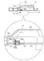
また、上記の操作線無効化部材2600に対し、球用開口(下皿球供給口323c)からセル板等の異物を差し込んで該セル板で操作線無効化部材2600への誘導部2754を塞ごうとするさらなる不正工作が考えられるが、これに対応すべく上述した実施形態では、ファール球の返却通路部1014の進路変更部分(本実施形態では下皿球供給口323c直上に対応する部分)に、かかるセル板(異物)が入り込むスリット1015を形成している(図6、図7参照)。これにより、球用開口(下皿球供給口323c)から異物を差し込んで誘導部2754を塞ごうとするさらなる不正工作も抑止することができる。なお、球用開口(下皿球供給口323c)からセル板等の異物を差し込んで誘導部2754を塞ごうとする不正工作の対応としては、上述のスリット1015のようにセル板等の異物を取り込む取り込み口を形成するものに限らず、図7に二点鎖線で示したように、セル板等の異物を衝突させて誘導部2754までの到達を阻害する突起状の障害部1016を設ける構成として、さらに高度な不正防止が達成できるようにしてもよい。
Further, a foreign object such as a cell plate is inserted into the operation line invalidating member 2600 from the sphere opening (lower dish ball supply port 323c), and the cell plate closes the guide portion 2754 to the operation line invalidating member 2600. In order to cope with this, in the above-described embodiment, the course changing portion of the foul ball return passage portion 1014 (the portion corresponding to the upper portion of the lower tray ball supply port 323c in this embodiment) is possible. In addition, a slit 1015 into which the cell plate (foreign material) enters is formed (see FIGS. 6 and 7). Thereby, the further unauthorized operation | work which inserts a foreign material from the opening for spheres (lower tray ball supply port 323c) and tries to block | guide the guidance part 2754 can also be suppressed. In addition, as a countermeasure against an unauthorized work to insert a foreign object such as a cell plate from the opening for the sphere (lower tray ball supply port 323c) and close the guide portion 2754, a foreign object such as a cell plate is used as in the slit 1015 described above. A configuration in which a projecting obstacle 1016 that impinges a foreign object such as a cell plate and impedes arrival to the guiding portion 2754 is provided, as shown by a two-dot chain line in FIG. As a result, a higher level of fraud prevention may be achieved.
また、これまで説明した第1、第2の操作線無効化部材260,2600は、操作線Lの進入を待って無効化する静的構造になっているが、図17、図18、図19、図20、図21に示したように、不正球Qの存在によって操作線Lを積極的に無効化する動的な操作線無効化部材2600Dにしてもよい。
Further, the first and second operation line invalidating members 260 and 2600 described so far have a static structure in which the operation line L is invalidated after the operation line L enters, but FIG. 17, FIG. 18, FIG. 20 and 21, a dynamic operation line invalidating member 2600D that actively invalidates the operation line L due to the presence of the illegal sphere Q may be used.
図17、図18、図19は、動的な操作線無効化部材2600Dの一つの具体例を示したものであり、その操作線無効化部材2600Dは、ファール球返却通路(返却通路部1014)の進路変更部(下皿球供給口323c直上に対応する角部)に揺動可能に軸着されている。
17, 18, and 19 show one specific example of the dynamic operation line invalidating member 2600D. The operation line invalidating member 2600D is a foul ball return passage (return passage portion 1014). Is pivotally attached to the path changing portion (the corner corresponding to the upper portion of the lower dish ball supply port 323c).
すなわち、操作線無効化部材2600Dは、図17において、水平な板状の球受部2645と、該球受部2645の右端に垂直に突設した板状の無効化部2646と、球受部2645と無効化部2646が交わる角部に形成した軸孔2647と、無効化部2646の上縁から右側に突設された前記軸孔2647を中心とする弧状の球止部2648と、を有し、前記軸孔2647にファールカバーユニット270に植設された支持軸2649が回転自在に挿通されていて、図18(a)の球受け姿勢から反時計回りに約90゜回転した図18(b)のリリース姿勢に揺動し得る。また、操作線無効化部材2600Dには、前記球受部2645と無効化部2646の軸孔2647を挟んだ反対側にバランスウェイト2650が設けられており、該バランスウェイト2650の付勢によって球受部2645に外力(具体的には遊技球1個分の荷重)が作用しない状態で図18(a)の球受け姿勢が保たれ、一方、球受部2645に遊技球1個分の荷重が作用したとき図18(b)のリリース姿勢に揺動するようになっている。
また、操作線無効化部材2600Dの無効化部2646の端縁は、軸孔2647を中心に旋回してファール球返却通路(返却通路部1014)を横切る交差辺部2651になっており、操作線無効化部材2600Dが図18(b)のリリース姿勢に揺動したとき該交差辺部2651がファール球返却通路の受部2652に嵌まるようになっている。
That is, the operation line invalidating member 2600D includes a horizontal plate-like ball receiving portion 2645, a plate-like invalidating portion 2646 that protrudes perpendicularly to the right end of the ball receiving portion 2645, and a ball receiving portion in FIG. A shaft hole 2647 formed at a corner where the disabling part 2646 and the disabling part 2646 intersect, and an arcuate ball stop 2648 centered on the shaft hole 2647 protruding from the upper edge of the disabling part 2646 to the right. Then, a support shaft 2649 implanted in the foul cover unit 270 is rotatably inserted in the shaft hole 2647, and is rotated about 90 ° counterclockwise from the ball receiving posture of FIG. It can swing to the release posture of b). The operation line invalidating member 2600D is provided with a balance weight 2650 on the opposite side of the ball receiving portion 2645 and the shaft hole 2647 between the invalidating portion 2646, and the ball receiving portion 2600D is energized by the bias of the balance weight 2650. 18A is maintained in a state where an external force (specifically, a load for one game ball) does not act on the portion 2645, while a load for one game ball is applied to the ball receiver 2645. When acted, it swings to the release posture of FIG. 18 (b).
Further, the edge of the disabling portion 2646 of the operation line disabling member 2600D is an intersecting side portion 2651 that turns around the shaft hole 2647 and crosses the foul ball return passage (return passage portion 1014). When the disabling member 2600D swings to the release posture shown in FIG. 18B, the intersecting side portion 2651 is fitted into the receiving portion 2652 of the foul ball return passage.
以上の動的な操作線無効化部材2600Dを備えたファールカバーユニット270に通常のファール球が流入した場合は、該ファール球が図18(a)のようにファール球返却通路の連絡通路2751を流下し、進路変更部で下向きに進路を変えた直後に球受け姿勢にある操作線無効化部材2600Dの球受部2645に載る。このファール球の荷重により操作線無効化部材2600Dが支持軸2649を中心に反時計回りに回動して図18(b)のリリース姿勢に変わる。そうすると操作線無効化部材2600Dの球受部2645に載っていたファール球が下流の貯留通路277に放出されるため、該ファール球から解放された操作線無効化部材2600Dがバランスウェイト2650の付勢により元の球受け姿勢に復動する。
なお、まれに複数のファール球が一度に発生する場合があるが、そうした場合でも先のファール球が操作線無効化部材2600Dで処理される間、後のファール球が図18(b)のように弧状の球止部2648で止められ、操作線無効化部材2600Dが復動してから続けて処理される。したがってファール球が複数個同時に発生しても、一個ずつ順番に支障なく処理することができる。
When a normal foul ball flows into the foul cover unit 270 having the dynamic operation line invalidating member 2600D described above, the foul ball passes through the communication passage 2751 of the foul ball return passage as shown in FIG. Immediately after flowing down and changing the course downward by the course changing unit, it is placed on the ball receiving part 2645 of the operation line invalidating member 2600D in the ball receiving attitude. Due to the load of the foul ball, the operation line invalidating member 2600D rotates counterclockwise about the support shaft 2649 and changes to the release posture shown in FIG. Then, the foul sphere placed on the ball receiving portion 2645 of the operation line invalidating member 2600D is released to the downstream storage passage 277, so that the operation line invalidating member 2600D released from the foul sphere is urged by the balance weight 2650. To return to the original ball receiving position.
In rare cases, a plurality of foul balls may be generated at one time. Even in such a case, while the previous foul ball is processed by the operation line invalidating member 2600D, the subsequent foul ball is as shown in FIG. The arc-shaped ball stop 2648 stops the operation line, and the operation line invalidating member 2600D is moved back to be processed. Therefore, even if a plurality of foul balls are generated simultaneously, they can be processed one by one without any trouble.
次に、動的な操作線無効化部材2600Dを備えたファールカバーユニット270に上記した不正行為B(操作線Lに複数の不正球Qをつなげてそのうちの1つを打球供給口252aから発射位置に送り込み、その不正球を意図的にファール球にして球用開口である下皿球供給口323cから取り出し、さらにその不正球に繋げられた操作線Lを掴んで後続の不正球Qを遊技領域5aに発射する不正行為)による不正球Qが流入した場合は、該不正球Qが図19(a)のように連絡通路2751を流下し、進路変更部で下向きに進路を変えた直後に球受け姿勢にある操作線無効化部材2600Dの球受部2645に載る。そしてこの不正球Qの荷重により操作線無効化部材2600Dが支持軸2649を中心に反時計回りに回動して図19(b)のリリース姿勢に変わる。このとき操作線無効化部材2600Dの無効化部2646も回動し、その端縁の交差辺部2651がファール球返却通路を横切って通路側の受部2652に嵌まるが、交差辺部2651がファール球返却通路を横切る際、そこを通る操作線Lも当然に横切るため、該操作線Lが図19(b)のように交差辺部2651と受部2652の間に挟まって動けない状態(挟止)になる。そうすると操作線Lに繋がっている不正球Qが落下不能になるため、操作線無効化部材2600Dの球受部2645が不正球Qから解放されずにリリース姿勢を継続することになる。もちろん操作線無効化部材2600Dは、球用開口たる下皿球供給口323cから手を入れても届かない位置にあるため、この位置に止まる不正球Qが外部から取り出されるおそれはない。
なお、交差辺部2651と受部2652の間で操作線Lを蛇行させるなどして操作線Lの逆進が困難になるようにしておけば、操作線無効化部材2600Dに捕捉された状態の不正球Qを打球供給口252a側に引き戻すことも困難になる。これにより操作線無効化部材2600Dに残った不正球Qを証拠球として保存・回収することができる。
Next, the fraud act B described above is connected to the foul cover unit 270 provided with the dynamic operation line invalidating member 2600D (a plurality of illegal balls Q are connected to the operation line L, and one of them is launched from the hitting ball supply port 252a. The illegal ball is intentionally made into a foul ball, taken out from the lower tray ball supply port 323c, which is the opening for the ball, and then the operation line L connected to the illegal ball is grasped to obtain the subsequent illegal ball Q as a game area. When the illegal ball Q due to the illegal act launched into 5a flows in, the illegal ball Q flows down the communication passage 2751 as shown in FIG. It is mounted on the ball receiving portion 2645 of the operation line invalidating member 2600D in the receiving posture. Then, the operation line invalidating member 2600D is rotated counterclockwise about the support shaft 2649 by the load of the irregular sphere Q to change to the release posture of FIG. At this time, the disabling part 2646 of the operation line disabling member 2600D also rotates, and the crossing edge part 2651 at the end of the operation line disabling member 2600D is fitted into the receiving part 2652 on the passage side across the foul ball return passage. When crossing the foul ball return passage, the operation line L passing there naturally also crosses, so that the operation line L is sandwiched between the intersecting side portion 2651 and the receiving portion 2652 as shown in FIG. Pinch). Then, since the illegal ball Q connected to the operation line L cannot fall, the ball receiving portion 2645 of the operation line invalidating member 2600D continues to be released without being released from the illegal ball Q. Of course, since the operation line invalidating member 2600D is in a position that cannot be reached even if a hand is put in from the lower dish ball supply port 323c that is a sphere opening, there is no possibility that the illegal sphere Q that stops at this position is taken out from the outside.
If it is made difficult for the operation line L to reversely move, for example, by meandering the operation line L between the intersecting side portion 2651 and the receiving portion 2652, the operation line L is captured by the operation line invalidating member 2600D. It is also difficult to pull the illegal ball Q back to the hitting ball supply port 252a. Thereby, the illegal sphere Q remaining on the operation line invalidating member 2600D can be stored and collected as a evidence sphere.
以上の動的な操作線無効化部材2600Dは、不正球Qの自重を利用したものであるが、該操作線無効化部材2600Dを図20に示したように電動駆動手段で作動させるようにしてもよい。
すなわち図20の操作線無効化部材2600Dは、前記のバランスウェイト2650を設けた部分に電動駆動手段たるソレノイド2653のプランジャ2654を連結すると共に操作線無効化部材2600Dの無効化部2646に球検出器2655を設けてなり、球受部2645に遊技球が載ってそれが球検出器2655によって検出されるとソレノイド2653のプランジャ2654が上昇して操作線無効化部材2600Dが球受け姿勢からリリース姿勢に変化し、また、球受部2645から遊技球が放出されてそれが球検出器2655によって検出(遊技球有りから無しへの信号の変化)されるとソレノイド2653のプランジャ2654が下降して操作線無効化部材2600Dがリリース姿勢から球受け姿勢に復動するようになっている。
斯かる操作線無効化部材2600Dの球受部2645に正常なファール球が載った場合は、ファール球の発生と放出が球検出器2655の信号の変化によって検出され、それを受けてソレノイド2653が適宜作動するため、自重利用の操作線無効化部材2600Dと同様にファール球が一個ずつ処理される。
一方、操作線無効化部材2600Dの球受部2645に不正球Qが載った場合は、不正球Qが球検出器2655で検出されるため、ソレノイド2653のプランジャ2654が上昇して操作線無効化部材2600Dが不正球Qを伴ってリリース姿勢に変化するものの、上記のように操作線Lが無効化部2646の交差辺部2651と受部2652に挟止されて不正球Qが落下せず、球検出器2655から放出の信号が発せられないため、ソレノイド2653のプランジャ2654が上昇位置に止まる。よって不正球Qが狙った球用開口から取り出せないため、不正を未然に防止することができる。
The dynamic operation line invalidating member 2600D described above uses the dead weight of the illegal sphere Q. However, the operation line invalidating member 2600D is operated by the electric drive means as shown in FIG. Also good.
That is, the operation line disabling member 2600D of FIG. 20 connects the plunger 2654 of the solenoid 2653 as an electric drive means to the portion where the balance weight 2650 is provided, and a ball detector connected to the disabling part 2646 of the operation line disabling member 2600D. 2655 is provided, and when a game ball is placed on the ball receiving portion 2645 and detected by the ball detector 2655, the plunger 2654 of the solenoid 2653 is raised, and the operation line invalidating member 2600D is changed from the ball receiving posture to the released posture. When the game ball is released from the ball receiving portion 2645 and is detected by the ball detector 2655 (change in signal from presence to absence of the game ball), the plunger 2654 of the solenoid 2653 is lowered and the operation line is changed. The disabling member 2600D returns from the release posture to the ball receiving posture. .
When a normal foul ball is placed on the ball receiving portion 2645 of the operation line invalidating member 2600D, generation and release of the foul ball are detected by a change in the signal of the ball detector 2655, and the solenoid 2653 is received in response thereto. In order to operate appropriately, foul balls are processed one by one in the same manner as the operation line invalidating member 2600D using its own weight.
On the other hand, when the illegal sphere Q is placed on the ball receiving portion 2645 of the operation line invalidating member 2600D, the illegal sphere Q is detected by the sphere detector 2655, so that the plunger 2654 of the solenoid 2653 is raised and the operation line is invalidated. Although the member 2600D changes to the release posture with the illegal sphere Q, as described above, the operation line L is pinched by the intersecting side portion 2651 and the receiving portion 2652 of the invalidating portion 2646, and the illegal sphere Q does not fall. Since no release signal is issued from the ball detector 2655, the plunger 2654 of the solenoid 2653 stops at the raised position. Therefore, since the illegal ball Q cannot be taken out from the target ball opening, it is possible to prevent fraud.
なお、上記した動的な操作線無効化部材2600Dは、無効化部2646の交差辺部2651及び/又は受部2652に切断刃を設けておくことにより、操作線Lを切断して無効化することができる。また、実施形態の操作線無効化部材2600Dは、球受部2645が返却通路部104を塞いだ状態で球用開口側からの不正球Qの侵入を阻止する機能を有するため、後述する不正球逆進防止手段として利用することもできる。よって、より高い不正防止機能を発揮する。
また、動的な操作線無効化部材2600Dは、上記の構成以外にも、例えば無効化部を、直線的に進退して連絡通路2751を開閉するシャッター板構造に形成すると共にそのシャッター板の先端をファール球返却通路を横切る交差辺部となし、また、連絡通路2751の流路の途中であって前記交差辺部の可動領域より下流に球検出器を設置すると共に交差辺部の可動領域を通過した後の不正球Qを該球検出器で検出して無効化部を作動させるようになし、そうして連絡通路2751を横切った交差辺部で操作線Lを挟止又は切断させるようにしてもよい。
また、上記した動的な操作線無効化部材2600Dは、球送りユニット250の第1の操作線無効化部材260に適用することもできる。具体的には、球送りユニット250に設けられている球送ソレノイド255を操作線無効化部材2600Dのソレノイド2653に置き換え、球送り部材254を操作線無効化部材2600Dに置き換える。この場合、不正球Qが球送りユニット250内に止まって球発射装置650へ供給されなくなるため、不正抑止効果を確実に高めることができる。
Note that the above-described dynamic operation line invalidating member 2600D cuts and invalidates the operation line L by providing a cutting blade in the intersecting side portion 2651 and / or the receiving portion 2652 of the invalidating portion 2646. be able to. Further, the operation line invalidating member 2600D of the embodiment has a function of preventing the intrusion of the illegal sphere Q from the sphere opening side with the ball receiving portion 2645 blocking the return passage portion 104. It can also be used as a reverse prevention means. Therefore, a higher fraud prevention function is exhibited.
In addition to the above configuration, the dynamic operation line disabling member 2600D has, for example, a disabling portion formed in a shutter plate structure that linearly advances and retracts to open and close the communication passage 2751 and the front end of the shutter plate. And a ball detector installed in the middle of the flow path of the connecting passage 2751 and downstream of the movable area of the intersection side, and the movable area of the intersection side The invalid ball Q after passing is detected by the ball detector so as to operate the invalidation unit, and the operation line L is pinched or cut at the crossing side crossing the communication passage 2751. May be.
The dynamic operation line invalidating member 2600D described above can also be applied to the first operation line invalidating member 260 of the ball feeding unit 250. Specifically, the ball feed solenoid 255 provided in the ball feed unit 250 is replaced with the solenoid 2653 of the operation line invalidating member 2600D, and the ball feed member 254 is replaced with the operation line invalidating member 2600D. In this case, since the illegal ball Q stops in the ball feeding unit 250 and is not supplied to the ball launching device 650, the illegal deterrent effect can be reliably increased.
また、図21は、動的な操作線無効化部材2600Dであって、操作線Lを巻き取って無効化するものである。
すなわち、この操作線無効化部材2600Dは、ファールカバーユニット270の連絡通路2751内に該通路と直交する向きの回転軸2656を中心に回転し得るように取り付けられた角リング状の無効化部2646と、該無効化部2646を回転させる電動駆動手段たるモーター2657と、該無効化部2646の連絡通路2751を横切る横棒を交差辺部2651として該交差辺部2651の可動(回転)領域より下流に設けられた球検出器2655と、からなり、該球検出器2655でファール球が検出される度に無効化部2646を1回転させるようにしたものである。
斯かる操作線無効化部材2600Dを備えたファールカバーユニット270に通常のファール球が流入した場合は、該ファール球が連絡通路2751に入って無効化部2646を潜り抜け、そのファール球が球検出器2655で検出されることで無効化部2646が1回空回りするが、ファール球はそのまま流下して球用開口から外部に放出される。
一方、この操作線無効化部材2600Dを備えたファールカバーユニット270に上記した不正行為Bによる不正球Qが流入した場合は、不正球Qが無効化部2646を潜った時点で操作線Lも無効化部2646を通るため、不正球Qが球検出器2655で検出されて無効化部2646が1回転すると操作線Lが無効化部2646に巻き付く。したがって不正球Qが連絡通路2751内に止まるため、不正者の手に渡るおそれがない。
なお、不正球Qを検出する球検出器2655は、不正球Qに付された操作線Lの張力を受けて変位するものでもよく、そうした場合は、不正球Qを確実に検出することができるため、前記した操作線Lを巻き取る操作線無効化部材2600Dの無駄な空回しをなくすることができる。
FIG. 21 shows a dynamic operation line disabling member 2600D that winds up the operation line L and disables it.
That is, the operation line invalidating member 2600D is a rectangular ring-shaped invalidating portion 2646 attached to the communication passage 2751 of the foul cover unit 270 so as to be able to rotate around the rotation shaft 2656 oriented in the direction orthogonal to the passage. And a motor 2657 which is an electric drive means for rotating the invalidating portion 2646, and a horizontal bar crossing the communication passage 2751 of the invalidating portion 2646 as an intersecting side portion 2651 downstream from the movable (rotating) region of the intersecting side portion 2651 The invalidation unit 2646 is rotated once each time a foul sphere is detected by the sphere detector 2655.
When a normal foul ball flows into the foul cover unit 270 provided with such an operation line invalidating member 2600D, the foul ball enters the communication passage 2751 and goes through the invalidating unit 2646, and the foul ball detects the ball. The invalidation unit 2646 idles once by being detected by the detector 2655, but the foul sphere flows down as it is and is discharged to the outside through the sphere opening.
On the other hand, when the illegal ball Q due to the illegal act B described above flows into the foul cover unit 270 provided with the operation line invalidating member 2600D, the operation line L is also invalidated when the illegal ball Q enters the invalidating unit 2646. Since the illegal sphere Q is detected by the sphere detector 2655 and the invalidation unit 2646 makes one rotation because it passes through the invalidation unit 2646, the operation line L is wound around the invalidation unit 2646. Therefore, since the illegal ball Q stops in the communication passage 2751, there is no possibility of getting into the hands of the unauthorized person.
Note that the sphere detector 2655 for detecting the illegal sphere Q may be displaced by receiving the tension of the operation line L attached to the illegal sphere Q. In such a case, the illegal sphere Q can be reliably detected. Therefore, it is possible to eliminate unnecessary idle rotation of the operation line invalidating member 2600D that winds up the operation line L described above.
以上、動的な操作線無効化部材に関する実施形態の説明には、次のような技術的思想が含まれる。
「遊技球で遊技を行う遊技領域と、
遊技球を発射する球発射装置と、
前記球発射装置の発射位置から前記遊技領域に連通する発射球通路を形成する発射通路部と、
前記発射球通路の途中に開設されたファール球落下口と機前の外部に遊技球を放出する球用開口とを結ぶファール球返却通路を形成する返却通路部と、
不正球に付された操作線の機前からの操作を防止し得る不正防止手段と、を備え、
前記不正防止手段は、前記操作線を挟止又は切断又は巻き取って無効化する操作線無効化部材であり、
該操作線無効化部材は、遊技球の前記ファール球返却通路を横切る交差辺部を備えると共に前記不正球が該交差辺部の可動領域を通過した後に該交差辺部を作動させて前記ファール球返却通路を横切らせるようになし、そうして前記交差辺部で前記ファール球返却通路を通る前記操作線を挟止又は切断又は巻き取って無効化するものであることを特徴とする遊技機。」
As described above, the following technical idea is included in the description of the embodiment relating to the dynamic operation line invalidating member.
“A game area where games are played with game balls,
A ball launcher that launches game balls;
A launch passage portion that forms a launch ball passage communicating with the game area from a launch position of the ball launch device; and
A return passage portion that forms a foul ball return passage that connects a foul ball drop opening that is established in the middle of the launch ball passage and a ball opening that discharges a game ball to the outside of the aircraft,
Fraud prevention means capable of preventing operation from the front of the operation line attached to the illegal ball,
The fraud prevention means is an operation line invalidating member that invalidates the operation line by pinching, cutting, or winding.
The operation line invalidating member includes an intersection side portion that traverses the foul ball return passage of the game ball, and operates the intersection side portion after the illegal ball passes through the movable region of the intersection side portion, thereby the foul ball. A gaming machine that traverses the return passage, and thus invalidates the operation line passing through the foul ball return passage at the intersection by pinching, cutting, or winding. "
[第3の不正防止手段(操作線無効化部材)]
次に、前記したファール球落下口1013に設けられた第3の不正防止手段は、図2A、図2B、図7、図15、図16に示したように、発射レール684の端部(終端部)に設けられた操作線無効化部材2600Hと外レール1001の端部(具体的には樹脂製のレール基台1001x)に設けられた操作線無効化部材2600Sとからなる。
[Third fraud prevention means (operation line invalidating member)]
Next, as shown in FIGS. 2A, 2B, 7, 15, and 16, the third fraud prevention means provided in the foul ball dropping opening 1013 is the end (end terminal) of the firing rail 684. And an operation line invalidating member 2600S provided at an end of the outer rail 1001 (specifically, a rail base 1001x made of resin).
発射レール684の飛び出し側の端部に設けられた操作線無効化部材2600Hは、鋭利な切断刃であり、その刃先に作業者の手が直接触れないように金属製の三角プレートを櫛歯状に並べた安全カバー部1017でカバーしてなる。なお、切断刃は、この安全カバー部1017によって支持されている。
したがって、前記のように、下皿球供給口323cからセル板等の専用工具を使って不正球Qを返却通路部1014に押し込んで逆流させ、球発射装置680の発射位置に送り込むような不正行為Aが行われた場合、不正球Qが発射レール684の端部に載って傾斜により転がって発射位置に向かうと、それに引っ張られて(張力が負荷されて)操作線Lが操作線無効化部材2600Hの切断刃に触れて切断される。よって操作線Lが操作できなくなる。
また、操作線Lに複数の不正球Qをつなげてそのうちの1つを打球供給口252aから発射位置に送り込み、それを意図的にファール球にして球用開口である下皿球供給口323cから不正球Qに繋げられた操作線Lを掴んで後続の不正球Qを遊技領域5aに発射する不正行為Bが行われた場合にも、不正球Qがファール球となって返却通路部1014を落下する過程で操作線Lが操作線無効化部材2600Hの切断刃に触れるため、その段階で切断される。よって操作線Lが操作できなくなる。
The operation line disabling member 2600H provided at the projecting side end of the firing rail 684 is a sharp cutting blade, and a metal triangular plate is comb-toothed so that the operator's hand does not directly touch the blade edge. It covers with the safety cover part 1017 arranged in order. The cutting blade is supported by the safety cover portion 1017.
Accordingly, as described above, an illegal act of pushing the illegal ball Q back into the return passage portion 1014 using a dedicated tool such as a cell plate from the lower tray ball supply port 323c and feeding it back to the launch position of the ball launcher 680. When A is performed, when the illegal ball Q is placed on the end of the launch rail 684 and rolls due to an inclination toward the launch position, it is pulled (tension is applied) and the operation line L becomes the operation line invalidating member. It is cut by touching a 2600H cutting blade. Therefore, the operation line L cannot be operated.
Further, a plurality of illegal balls Q are connected to the operation line L and one of them is sent from the hitting ball supply port 252a to the launch position, and is intentionally made into a foul ball from the lower dish ball supply port 323c which is a ball opening. Even when an illegal act B is performed in which the operation line L connected to the illegal ball Q is grabbed and the subsequent illegal ball Q is launched into the game area 5a, the illegal ball Q becomes a foul ball and the return passage portion 1014 is Since the operation line L touches the cutting blade of the operation line invalidating member 2600H in the process of dropping, the operation line L is cut at that stage. Therefore, the operation line L cannot be operated.
一方、外レール1001を構成する樹脂製のレール基台1001xに設けられた操作線無効化部材2600Sは、図2A、図7及び図15に示したように硬質樹脂製の線材をブラシ状に多数突設してなる。
かかる操作線無効化部材2600Sによれば、仮に不正球Qが遊技領域5aに到達して操作線Lにつながった状態でぶら下がり、その操作線Lの端を球用開口である下皿球供給口323cを介して不正者が掴んでいるとしても、遊技領域5aの不正球Qを上昇させるべく操作線Lを外部から引っ張ったとき、その張力により操作線Lが操作線無効化部材2600Sの線材同士の間に入り込むため、その後、不正球Qを下降させるべく操作線Lを操る手の力を緩めても、操作線Lが操作線無効化部材2600Sの線材群から受ける抵抗で滑りにくくなっているから緩めた手の動きが不正球Qに伝わらない。つまり遊技領域5aにある不正球Qが下げられないため、結果的に不正球Qを用いた不正行為を抑止することができる。
On the other hand, the operation line invalidating member 2600S provided on the resin rail base 1001x constituting the outer rail 1001 has a large number of hard resin wires in a brush shape as shown in FIGS. 2A, 7 and 15. Protruding.
According to the operation line invalidating member 2600S, if the illegal ball Q reaches the game area 5a and hangs in a state of being connected to the operation line L, the end of the operation line L is a lower tray ball supply port which is a ball opening. Even if an unauthorized person is grasping via 323c, when the operation line L is pulled from the outside to raise the illegal ball Q in the game area 5a, the operation line L is pulled between the wires of the operation line invalidating member 2600S by the tension. After that, even if the hand that manipulates the operation line L to lower the illegal ball Q is loosened, the operation line L is less likely to slip due to the resistance received from the wire group of the operation line invalidating member 2600S. The movement of the loosened hand is not transmitted to the illegal ball Q. That is, since the illegal ball Q in the game area 5a cannot be lowered, the illegal act using the illegal ball Q can be suppressed as a result.
このように第3の不正防止手段は、不正行為A、Bの初期段階で発射レール684側の操作線無効化部材2600Hが効果を発揮し、また、仮にそれが破られたとしても外レール1001側の操作線無効化部材2600Sが効果を発揮するため、より高度な不正防止効果が得られる。
なお、操作線無効化部材2600H,2600Sの何れか一方を単独で使用することももちろん可能であり、また、操作線無効化部材2600Hと操作線無効化部材2600Sの具体的な無効化部材も実施形態同士で入れ替えたり、同じ無効化部材を採用してもよい。
また、操作線無効化部材2600H,2600Sを実施形態のように別部品化して発射レール684や外レール1001に取り付ける場合の他、例えば発射レール684を構成する金属板を適宜加工して操作線無効化部材2600Hを一体に形成したり、或は外レール1001を構成する樹脂製のレール基台1001xに線材を一体成形するか、または該レール基台1001xの角部に図2BのようにV溝状の挟止部2600Svを刻設し該挟止部2600Svの溝奥に操作線Lを誘引して挟止するようにしてもよい。
さらにまた、外レール1001の操作線無効化部材2600Sを、図16に示したように第2の操作線無効化部材2600と同じ構成、例えば図9、図10で説明した二枚の金属板2611,2622で形成し、外レール1001のレール基台1001xに第一の傾斜部2754aと第二の傾斜部2754bとからなる誘導部2754を設ける構成にしてもよい。
Thus, the third fraud prevention means is effective in the operation line disabling member 2600H on the launch rail 684 side in the initial stage of fraud A and B, and even if it is broken, the outer rail 1001 Since the operation line invalidating member 2600S on the side exhibits the effect, a higher level of fraud prevention effect can be obtained.
Of course, either one of the operation line invalidating members 2600H and 2600S can be used alone, and a specific invalidating member of the operation line invalidating member 2600H and the operation line invalidating member 2600S is also implemented. The forms may be interchanged or the same invalidating member may be employed.
Further, in addition to the case where the operation line invalidating members 2600H and 2600S are made as separate parts and attached to the firing rail 684 or the outer rail 1001 as in the embodiment, for example, the metal plate constituting the firing rail 684 is appropriately processed to invalidate the operation line. The forming member 2600H is integrally formed, or a wire rod is integrally formed on a resin-made rail base 1001x constituting the outer rail 1001, or a V-groove is formed at a corner of the rail base 1001x as shown in FIG. 2B. It is also possible to engrave a pin-shaped clamping part 2600Sv and attract the operation line L to the back of the groove of the clamping part 2600Sv.
Furthermore, the operation line disabling member 2600S of the outer rail 1001 has the same configuration as the second operation line disabling member 2600 as shown in FIG. 16, for example, the two metal plates 2611 described in FIG. 9 and FIG. , 2622, and a guide portion 2754 including a first inclined portion 2754a and a second inclined portion 2754b may be provided on the rail base 1001x of the outer rail 1001.
以上、不正球Qに取り付けられた操作線Lを無効化する第2の操作線無効化部材2600を返却通路部1014に設ける実施形態について、また、同じく第3の操作線無効化部材2600をファール球落下口1013に設ける実施形態について説明したが、もちろん本発明は上記実施形態に限定されるものではない。
例えば、上記実施形態では操作線無効化部材2600をファール球受部275の底壁2750と連絡通路2751の上部通路壁2752との折り返し部分、つまり連絡通路2751の入口部分に設けたが、当該操作線無効化部材2600を連絡通路2751の出口部分(図7矢示z参照)に設けたり、図6(a)の球放出口276の後面側に設けたり、ファール球落下口1013を構成する外レール1001の始端部と発射レール684の終端部のそれぞれに設ける等、操作線Lが返却通路部1014の一部に当接して屈曲する部位であって操作線Lが不正球Qの重量等と不正者による引張り力とによる張力を受けて真っ直ぐ張ろうとした場合に押圧力を受ける部位であることを条件として、返却通路部1014内のどの位置に設けるようにしてもよい。なお、実施形態の操作線無効化部材2600の設置位置は、球用開口から遊技者が指先を挿入しても触れることができない位置としており、この位置が、遊技者の安全面及び操作線無効化部材2600自体に対する不正工作が困難になる防犯面を考慮すると好ましい。
As described above, in the embodiment in which the second operation line disabling member 2600 for disabling the operation line L attached to the illegal ball Q is provided in the return passage portion 1014, the third operation line disabling member 2600 is similarly set to the foul. Although the embodiment provided in the ball dropping opening 1013 has been described, of course, the present invention is not limited to the above embodiment.
For example, in the above embodiment, the operation line invalidating member 2600 is provided in the folded portion between the bottom wall 2750 of the foul ball receiving portion 275 and the upper passage wall 2752 of the communication passage 2751, that is, the entrance portion of the communication passage 2751. The line invalidating member 2600 is provided at the exit portion of the communication passage 2751 (see z in FIG. 7), the rear surface side of the ball discharge port 276 in FIG. The operation line L is a part where the operation line L is bent in contact with a part of the return passage portion 1014, such as being provided at each of the start end of the rail 1001 and the end of the firing rail 684, and the operation line L is the weight of the illegal sphere Q, etc. It should be provided at any position in the return passage portion 1014 on the condition that it is a portion that receives a pressing force when it tries to be stretched straight by receiving a tension due to a pulling force by an unauthorized person. It may be. In addition, the installation position of the operation line invalidating member 2600 of the embodiment is a position where the player cannot touch the fingertip even if the fingertip is inserted from the opening for the ball, and this position is the player's safety aspect and the operation line invalidity. It is preferable in consideration of a crime prevention surface that makes it difficult to perform illegal manipulation on the adjusting member 2600.
また、実施形態では操作線無効化部材2600を連絡通路2751の一方に片寄せて設けるようにしたが、図12(a),(b)のように通路幅一杯に操作線無効化部材2600として切断刃を配置するようにしてもよい。なお、図12(a),(b)では、ファール球受部275の底壁2750の終端部分と連絡通路2751の始端部分を櫛歯状の安全カバー部1017にして切断刃の刃先が作業者に触れないようになっている。この場合の操作線無効化部材2600の切断刃は、周知の折れ刃構造又はチップ構造のものを使用し、これを上部通路壁2752の上面の鞘状ホルダー部1018に設置すると共にユニット本体271と蓋部材272の夫々に装填口1019と排出口1020を設け、そうして切断刃をところてん式に押し出して新旧交換し得るようにすれば、常にシャープな切れ味を持続させることができる。
その他、図12(a),(b)において符合1021は、前記安全カバー部1017の谷部に切り込んだ操作線L用の挟止割線部であり、該挟止割線部1021に操作線Lが食い込み得るようになっている。したがって、もし仮に切断刃の操作線無効化部材2600が操作線Lの切断に失敗したとしても、底壁2750等の前記挟止割線部1021に操作線Lが食い込み得るため、不正防止の確実性が向上する。
In the embodiment, the operation line disabling member 2600 is provided to be shifted to one side of the communication passage 2751. However, as shown in FIGS. 12A and 12B, the operation line disabling member 2600 is filled to the full width of the passage. A cutting blade may be arranged. 12 (a) and 12 (b), the end of the bottom wall 2750 of the foul ball receiver 275 and the start of the communication passage 2751 are the comb-shaped safety cover 1017, and the cutting edge of the cutting blade is the operator. Is not touching. In this case, the cutting blade of the operation line disabling member 2600 uses a well-known broken blade structure or chip structure, which is installed in the sheath-like holder portion 1018 on the upper surface of the upper passage wall 2752 and the unit main body 271. If the loading port 1019 and the discharge port 1020 are provided in each of the lid members 272 so that the cutting blade can be pushed out in place, and the old and new can be exchanged, the sharpness can always be maintained.
In addition, in FIGS. 12A and 12B, reference numeral 1021 denotes a clip part for the operation line L cut into the trough of the safety cover part 1017, and the operation line L is connected to the clip part 1021. You can bite in. Therefore, even if the operation line disabling member 2600 of the cutting blade fails to cut the operation line L, the operation line L can bite into the holding split line portion 1021 such as the bottom wall 2750 and the like. Will improve.
また、上述の実施形態ではファール球が下皿に返却される例を示したが、ファール球が上皿(下皿がない場合を含む)に返却される構造の遊技機もあり、こうした遊技機の場合、上皿球供給口(球用開口)から遊技領域5aに連通する空間を用いて、操作線Lを取付けた不正球Qを遊技領域5aに侵入させる不正行為(上述した不正行為A、Bに類似する不正行為)が行われる虞がある。こうした遊技機の場合には、上皿球供給口から遊技領域5aに連通する空間に位置するファール返却通路の所定部位に、上述した実施例と同様に第2の不正防止手段を設けることが例示できる。
Moreover, although the example in which the foul ball is returned to the lower plate is shown in the above-described embodiment, there is a gaming machine having a structure in which the foul ball is returned to the upper plate (including the case where there is no lower plate). In this case, using a space communicating from the upper bowl supply port (ball opening) to the game area 5a, a fraudulent act of intruding the illegal ball Q attached with the operation line L into the game area 5a (the fraud A, A fraudulent act similar to B) may occur. In the case of such a gaming machine, it is exemplified that the second fraud prevention means is provided at a predetermined portion of the foul return passage located in a space communicating from the upper tray ball supply port to the gaming area 5a as in the above-described embodiment. it can.
また、上述の実施形態では、返却通路部1014を構成するファールカバーユニット270を扉枠3側に設けたが、該ファールカバーユニット270は本体枠4側に設けてもよい。これにより、装飾変更等により扉枠3側だけを交換する際にも、第2の不正防止手段を有するファールカバーユニット270を流用することが可能になる。
In the above-described embodiment, the foul cover unit 270 constituting the return passage portion 1014 is provided on the door frame 3 side. However, the foul cover unit 270 may be provided on the main body frame 4 side. Thereby, even when only the door frame 3 side is replaced due to a decoration change or the like, the foul cover unit 270 having the second fraud prevention means can be diverted.
また、上述の実施形態では、返却通路部1014を構成するファールカバーユニット270に第2の不正防止手段を一つ設けるようにしたが、複数設けるようにしてもよい。例えば、返却通路部1014に上述した実施形態の折り返し部分のような屈曲部が複数形成される通路構成の場合、屈曲部の各々に(折り返し部分の各々に)、上述した実施形態のような第2の不正防止手段を設けるようにしてもよい。これにより、不正球Qを用いた不正行為の抑止効果を一層高めることが可能となる。
Further, in the above-described embodiment, one second fraud prevention unit is provided in the foul cover unit 270 constituting the return passage unit 1014, but a plurality of the second fraud prevention units may be provided. For example, in the case of a passage configuration in which a plurality of bent portions such as the folded portion of the above-described embodiment are formed in the return passage portion 1014, each of the bent portions (for each of the folded portions), Two fraud prevention means may be provided. Thereby, it becomes possible to further enhance the deterrence effect of fraud using the illegal ball Q.
また、上述の実施形態では、返却通路部1014を構成するファールカバーユニット270に第2の不正防止手段として金属板を設けるようにしたが、金属板でなく同様の構成の樹脂成型物を設けるものとしたり、あるいは、ファールカバーユニット270の成型そのものを特殊な形状として第2の不正防止手段として機能し得るようにしてもよい。例えば、前述した実施形態における第2の不正防止手段である金属板を設けず、代わりに、ファール球受部275の底壁2750と連絡通路2751の上部通路壁2752との折り返し部分に設けられるテーパ状の誘導部2754の最も幅が狭い部分(最狭部分)で操作線Lを捕獲し得るように、返却通路部1014を構成する樹脂成型部品にスリット状の捕獲部を形成するようにしておき、この誘導部2754の最狭部分である捕獲部で不正球Qに取り付けられた操作線Lが挟止される構成としてもよい。このような構成でも、上述した実施形態と同等の不正抑止効果を奏することができる。
Further, in the above-described embodiment, the metal plate is provided as the second fraud prevention means in the foul cover unit 270 constituting the return passage portion 1014. However, a resin molded product having the same configuration is provided instead of the metal plate. Or, the molding itself of the foul cover unit 270 may have a special shape so as to function as the second fraud prevention means. For example, the metal plate which is the second fraud prevention means in the above-described embodiment is not provided, but instead, a taper provided at a folded portion between the bottom wall 2750 of the foul ball receiving portion 275 and the upper passage wall 2752 of the communication passage 2751. The slit-shaped capture portion is formed in the resin molded part constituting the return passage portion 1014 so that the operation line L can be captured at the narrowest portion (narrowest portion) of the guide portion 2754 in the shape of a tube. The operation line L attached to the illegal sphere Q may be clamped by the capture part which is the narrowest part of the guide part 2754. Even with such a configuration, an illegal deterrent effect equivalent to that of the above-described embodiment can be achieved.
また、上述の実施形態では不正球Qに取り付けられた操作線Lを操作線無効化部材2600によって切断又は挟止するようにしたが、上述した不正行為Aの対策に特化したものとして、図13,図14,図17では、正常なファール球の流下に影響を与えることなく、球用開口からの不正球Qの侵入を阻止する(不正球Qの逆進・逆流を阻止する)不正球逆進防止手段を設けることによって、不正球Qによる不正を防止するようにしている。
具体的には、図13のように、返却通路部1014の進路変更部(下皿球供給口323c直上に対応する部分)に、例えば不正球Qを押し込むセル板(異物)のような専用工具だけでなく、不正球Qそのものを別通路に誘引して動きを封じるための誘引部1022を設けることが例示できる(第1の不正球逆進防止手段)。これにより、正常なファール球の流下に影響を与えることなく、上述した不正行為Aのような不正球Qを逆流させる不正行為を抑止できる。加えて、誘引部1022の入口部分に、逆流した不正球Qの該誘引部1022への侵入方向にのみ揺動可能な捕獲弁(誘引部1022への侵入を許容し、且つ、誘引部1022からの離脱を不能とする片開き式の弁、図示省略)を設けるようにしてもよく、これにより不正球Qを使用した痕跡、不正行為を行った証拠を残すことができる。
また、図14のように、返却通路部1014の所定部位に遊技球の流下方向にのみ揺動可能な逆止弁1023を設けて、不正球Qの逆進(逆流)を阻止することが例示できる(第2の不正球逆進防止手段)。このような構成によっても、正常なファール球の流下に影響を与えることなく、上述した不正行為Aのような不正球Qを逆流させる不正行為を抑止できる。なお、図17の操作線無効化部材2600Dも一種の逆止弁であり、前記逆止弁1023と同様な効果を発揮する。
また、上記した静的な操作線無効化部材と動的な操作線無効化部材は、両方を兼ね備えるようにしてももちろんよい。
Further, in the above-described embodiment, the operation line L attached to the illegal sphere Q is cut or pinched by the operation line invalidating member 2600. However, as shown in FIG. 13, 14, and 17, an illegal sphere that prevents the intrusion of the illegal sphere Q from the opening for the sphere without preventing the normal foul sphere from flowing down (inhibits the backward or reverse flow of the illegal sphere Q). By providing a reverse prevention means, fraud due to the illegal ball Q is prevented.
Specifically, as shown in FIG. 13, a dedicated tool such as a cell plate (foreign material) that pushes the illegal ball Q into the course changing portion of the return passage portion 1014 (the portion corresponding to the portion directly above the lower dish ball supply port 323 c). In addition, it is possible to exemplify the provision of an attracting part 1022 for attracting the illegal sphere Q itself to another passage and sealing the movement (first illegal sphere reverse prevention means). As a result, it is possible to suppress an illegal act that causes the illegal sphere Q to flow backward, such as the above-described illegal action A, without affecting the flow of the normal foul sphere. In addition, a trapping valve capable of swinging only in the intrusion direction of the backflowed illegal sphere Q into the attraction portion 1022 at the inlet portion of the attraction portion 1022 (allowing intrusion into the attraction portion 1022 and from the attraction portion 1022) A single-opening valve (not shown) that makes disengagement of the sphere Q not shown) may be provided, so that a trace using the illegal sphere Q and evidence of the illegal act can be left.
In addition, as shown in FIG. 14, it is exemplified that a check valve 1023 that can swing only in the flow-down direction of the game ball is provided at a predetermined portion of the return passage portion 1014 to prevent the illegal ball Q from moving backward (back flow). Yes (second illegal ball reverse prevention means). Even with such a configuration, it is possible to suppress an illegal act that causes the illegal sphere Q to flow backward, such as the above-described illegal act A, without affecting the normal flow of the foul sphere. Note that the operation line invalidating member 2600D in FIG. 17 is also a kind of check valve, and exhibits the same effect as the check valve 1023.
Of course, the static operation line invalidation member and the dynamic operation line invalidation member described above may both be provided.
[遊技盤の全体構成]
次に、パチンコ機1の遊技盤5の全体構成について、図22乃至図42を参照して詳細に説明する。
前記のように遊技盤5は、図1、図2、図25、図26等に示したように外レール1001と内レール1002で区画された遊技領域5aを有する遊技パネル1100と、該遊技パネル1100の裏側に設けられる演出ユニット1200と、を備えている。
[Overall configuration of game board]
Next, the overall configuration of the game board 5 of the pachinko machine 1 will be described in detail with reference to FIGS.
As described above, the gaming board 5 includes the gaming panel 1100 having the gaming area 5a defined by the outer rail 1001 and the inner rail 1002, as shown in FIGS. 1, 2, 25, 26, and the like, and the gaming panel. And an effect unit 1200 provided on the back side of 1100.
[遊技パネル]
遊技パネル1100は、外レール1001と内レール1002を有する枠状の前構成部材1000と、該前構成部材1000に裏側から嵌め込まれてその前面に遊技領域5aが形成される透明な樹脂板1110と、その樹脂板1110のほぼ中央に開設された開口1111の内周を縁取るように取り付けられた枠状で透明なセンター役物1028(図26参照)と、前記した入賞口1024、始動入賞口1025、アウト誘導部1003、風車、障害釘等が設けられている。そして、これらのなかの前記障害釘とアウト誘導部1003を除く殆どの部材が透明な樹脂で形成されており、したがって遊技領域5aの裏側、すなわち演出ユニット1200が遊技者から良好に見通せる。
[Game panel]
The gaming panel 1100 includes a frame-shaped front component member 1000 having an outer rail 1001 and an inner rail 1002, and a transparent resin plate 1110 that is fitted into the front component member 1000 from the back side and has a game area 5a formed on the front surface thereof. The frame-shaped and transparent center accessory 1028 (see FIG. 26) attached so as to border the inner periphery of the opening 1111 opened almost at the center of the resin plate 1110, the above-described winning port 1024, and the starting winning port 1025, an out guide part 1003, a windmill, an obstacle nail, and the like are provided. Of these, most members except the obstacle nail and the out guiding part 1003 are formed of a transparent resin, so that the back side of the game area 5a, that is, the effect unit 1200 can be seen well from the player.
[センター役物]
センター役物1028は、前記のように枠状に形成されており、図23において左側の外周面に遊技領域5aからの遊技球が進入可能なように開口しているワープ入口1029と、そのワープ入口1029に進入した遊技球をセンター役物1028内に流入させるワープ出口1030と、ワープ出口1030から放出された遊技球を左右方向に遊動させた後に遊技領域5a内へ落下させるステージ棚1031と、を備えている。
[Center character]
The center accessory 1028 is formed in a frame shape as described above, and in FIG. 23, the warp inlet 1029 opened so that a game ball from the game area 5a can enter the outer peripheral surface on the left side, and its warp. A warp outlet 1030 for allowing game balls that have entered the entrance 1029 to flow into the center accessory 1028; a stage shelf 1031 for causing the game balls released from the warp outlet 1030 to move in the left-right direction and then falling into the game area 5a; It has.
なお、遊技領域5aのステージ棚1031の直下には始動入賞口1025が配置されており、ステージ棚1031の中央から遊技球が下方へ落下すると、高い確率で始動入賞口1025に入球する。
また、センター役物1028は、外レール1001に沿って自己の上部を飛び越えた遊技球を遊技領域5aの右側下方に案内する右打ち案内通路1032が設けられている。この右打ち案内通路1032は、ほぼ遊技球一個分の広さを有すると共に通路内の正面視右内壁と同左内壁に蒲鉾状の障害凸条1033が互い違いにほぼ等ピッチに突設されている。したがって、この右打ち案内通路1032に入った遊技球は、多数の障害凸条1033に接触し蛇行しながら、あたかも遊技領域5a内で障害釘に衝突しながら落下するかのような状態で適度な時間を掛けて遊技領域5aの右側下方に導かれる。
また、センター役物1028は、遊技パネル1100の樹脂板1110の前面より前方へ突出する囲い枠1034よってステージ棚1031を除外する状態で周囲が囲われており、これにより遊技領域5a内に打ち込まれた遊技球が枠内(開口1111内)に侵入しないようになっている。
Note that a start winning opening 1025 is arranged immediately below the stage shelf 1031 in the game area 5a, and when a game ball falls downward from the center of the stage shelf 1031, it enters the start winning opening 1025 with a high probability.
The center accessory 1028 is provided with a right-handed guide passage 1032 for guiding a game ball jumping over the upper part of the center accessory 1028 to the lower right side of the game area 5a. This right-handed guide passage 1032 has a size corresponding to approximately one game ball, and hook-shaped obstacle protrusions 1033 are alternately projected at substantially equal pitches on the right inner wall and the left inner wall in front view in the passage. Accordingly, the game ball that has entered the right-handed guide passage 1032 comes in contact with a number of obstacle protrusions 1033 and meanders as if it falls while colliding with the obstacle nail in the game area 5a. It is led to the lower right side of the game area 5a over time.
The center accessory 1028 is surrounded by a surrounding frame 1034 protruding forward from the front surface of the resin plate 1110 of the game panel 1100 in a state where the stage shelf 1031 is excluded, and is thus driven into the game area 5a. The game ball is prevented from entering the frame (inside the opening 1111).
[演出ユニット]
遊技パネル1100の裏側に取り付けられる演出ユニット1200は、図25に示したように、後壁に前記表示装置1201を有する前面が開口する箱状の演出ケース体1202を備えており、該演出ケース体1202の内部に、表示装置1021に近い方から順に、可動装飾部1204と、導光板ユニット1205と、透明発光装飾手段1206と、が設けられている。
[Direction unit]
As shown in FIG. 25, the effect unit 1200 attached to the back side of the game panel 1100 includes a box-like effect case body 1202 having a front surface having the display device 1201 on the rear wall, and the effect case body. A movable decorative portion 1204, a light guide plate unit 1205, and transparent light emitting decorative means 1206 are provided inside 1202 in order from the side closer to the display device 1021.
[演出ケース体]
演出ケース体1202は、前面に遊技パネル1100の外形とほぼ同じ大きさの開口を有する前面開口状の箱であって、後壁に液晶等の表示装置1201が装着されている。
また、演出ケース体1202には、底壁に遊技パネル1100の入賞口1024や始動入賞口1025に連通する球誘導路1203が形成されており、該球誘導路1203に始動入賞口1025の入賞球センサ1025sや入賞口1024の入賞球センサが設けられている。
[Production case body]
The effect case body 1202 is a box having a front opening shape having an opening substantially the same as the outer shape of the game panel 1100 on the front surface, and a display device 1201 such as a liquid crystal is mounted on the rear wall.
In addition, the production case body 1202 is formed with a ball guiding path 1203 communicating with the winning opening 1024 of the gaming panel 1100 and the starting winning opening 1025 on the bottom wall, and the winning ball of the starting winning opening 1025 is connected to the ball guiding path 1203. A winning ball sensor such as a sensor 1025s or a winning opening 1024 is provided.
[可動装飾部]
実施形態の可動装飾部1204は、表示装置1201と導光板ユニット1205との間の空間に設けられた第1可動装飾体1207と、第2可動装飾体1208と、第3可動装飾体1209とからなる。
この第1〜第3可動装飾体1207,1208,1209は、それぞれが逆五角形をデザインのモチーフにしたものであり、最も前方に位置する第1可動装飾体1207が小さい逆五角形の第1造形物1210を、中間に位置する第2可動装飾体1208が前記第1造形物1210を囲い得るリング型の第2造形物1211を、また、最も後方に位置する第3可動装飾体1209が表示装置1201の表示面1201gのほぼ全体を覆い得る大きい逆五角形の第3造形物1212を備えている。
[Moving decorative part]
The movable decorative portion 1204 of the embodiment includes a first movable decorative body 1207, a second movable decorative body 1208, and a third movable decorative body 1209 provided in a space between the display device 1201 and the light guide plate unit 1205. Become.
Each of the first to third movable decorative bodies 1207, 1208, and 1209 has an inverted pentagon as a design motif, and the first movable decorative body 1207 positioned in the forefront is a small inverted pentagonal first shaped object. The second movable decorative body 1208 positioned in the middle of 1210 is the ring-shaped second molded object 1211 that can surround the first molded object 1210, and the third movable decorative body 1209 positioned rearmost is the display device 1201. A large inverted pentagonal third shaped article 1212 that can cover substantially the entire display surface 1201g.
[第1可動装飾体]
第1可動装飾体1207は、図34に示したように、固定的な支持板1213と、該支持板1213の一側に上向きに突設した縦レール1214と、該縦レール1214に対して上下摺動自在に取り付けられた前記第1造形物1210と、前記支持板1213の前記縦レール1214とは反対側の端に揺動自在に取り付けられた第1原動リンク1215と、該第1原動リンク1215に第1歯車群1216を介して連結された第1モータ1217と、からなる。そして、第1原動リンク1215の先端が第1造形物1210に連結されており、したがって、第1原動リンク1215を上下方向に揺動させることによって第1造形物1210が、図36実線に示したようにセンター役物1028の枠内の下方に自己の頂部が若干臨む高さの通常位置と、同図想像線に示したようにセンター役物1028の枠内のほぼ中央に位置する変化位置との間で昇降し得る。なお、第1造形物1210には発光体(図示せず)が設けられており、第1造形物1210は発光体と一体になって、通常位置と変化位置との間での昇降移動が可能に構成されている。
[First movable decorative body]
As shown in FIG. 34, the first movable decorative body 1207 includes a fixed support plate 1213, a vertical rail 1214 protruding upward on one side of the support plate 1213, and an upper and lower side with respect to the vertical rail 1214. The first model 1210 slidably attached, the first driving link 1215 slidably attached to the end of the support plate 1213 opposite to the vertical rail 1214, and the first driving link The first motor 1217 is connected to the 1215 via the first gear group 1216. And the front-end | tip of the 1st driving link 1215 is connected with the 1st modeled object 1210, Therefore, the 1st modeled object 1210 was shown to the solid line in FIG. 36 by rocking | fluctuating the 1st driving link 1215 to an up-down direction. As shown in the imaginary line in the figure, as shown in the imaginary line in the figure, a change position located almost at the center in the frame of the center accessory 1028 Can move up and down. The first modeled object 1210 is provided with a light emitter (not shown), and the first modeled object 1210 is integrated with the light emitter and can be moved up and down between the normal position and the change position. It is configured.
[第2可動装飾体]
第2可動装飾体1208は、図37に示したように、固定的な額縁状の支持フレーム1218と、該支持フレーム1218の上部に上下摺動自在に取り付けられた第2造形物1211の上辺部1219と、該上辺部1219の両端に回動自在に軸着された第2造形物1211の斜辺部1220と、支持フレーム1218の上部に揺動自在に軸着された第2原動リンク1221と、該第2原動リンク1221に第2歯車群1222を介して連結された第2モータ1253と、からなる。そして、第2原動リンク1221が第2造形物1211の上辺部1219と斜辺部1220の各長孔に摺動且つ回動可能に軸着されており、したがって第2原動リンク1221を上下方向に揺動させることによって、第2造形物1211の上辺部1219が、図38実線に示したように支持フレーム1218の上部に沿った通常位置と、同図想像線に示したように表示装置1201の表示面1201gの前面上方に出現する変化位置との間で昇降し、さらに第2造形物1211の斜辺部1220が、図38実線に示したように支持フレーム1218の側部に沿った通常位置と、同図想像線に示したように表示装置1201の表示面1201gの前面側方に出現して前記上辺部1219とリング型に合体する変化位置との間で揺動し得る。なお、第2造形物1211は、変化位置にあるときリング型の逆五角形を呈するが、そのリングのほぼ中心に前記第1可動装飾体1207の第1造形物1210が正面視で位置し得る。
[Second movable decorative body]
As shown in FIG. 37, the second movable decorative body 1208 includes a fixed frame-shaped support frame 1218 and an upper side portion of the second model 1211 that is slidably attached to the upper portion of the support frame 1218. 1219, the oblique side portion 1220 of the second shaped article 1211 pivotally attached to both ends of the upper side portion 1219, a second driving link 1221 pivotally attached to the upper portion of the support frame 1218, A second motor 1253 connected to the second driving link 1221 via a second gear group 1222. The second driving link 1221 is slidably and pivotally attached to the long holes of the upper side portion 1219 and the oblique side portion 1220 of the second shaped article 1211. Therefore, the second driving link 1221 is swung up and down. By moving, the upper side 1219 of the second modeled object 1211 is displayed at the normal position along the upper portion of the support frame 1218 as shown by the solid line in FIG. 38 and the display of the display device 1201 as shown by the imaginary line in the figure. It moves up and down between the change position appearing above the front surface of the surface 1201g, and the oblique side portion 1220 of the second modeled object 1211 has a normal position along the side portion of the support frame 1218 as shown by the solid line in FIG. As shown by the imaginary line in the figure, it appears on the front side of the display surface 1201g of the display device 1201 and can swing between the upper side portion 1219 and the change position combined with the ring shape. Note that the second modeled object 1211 has a ring-shaped inverted pentagon when in the change position, but the first modeled object 1210 of the first movable decorative body 1207 can be positioned in a front view substantially at the center of the ring.
[第3可動装飾体]
第3可動装飾体1209は、表示装置1201の表示面1201gのほぼ全体を覆い得る大きい逆五角形の第3造形物1212を有するが、該第3造形物1212は、上パネル1223と中パネル1224と下パネル1225に三分割されており、そのうちの上パネル1223と中パネル1224が図40に示した上半部1226に組み込まれ、残りの下パネル1225が図41に示した下半部1227に組み込まれている。
[Third movable ornament]
The third movable decorative body 1209 has a large inverted pentagonal third shaped article 1212 that can cover almost the entire display surface 1201g of the display device 1201, and the third shaped article 1212 includes an upper panel 1223, a middle panel 1224, and the like. The lower panel 1225 is divided into three parts, of which the upper panel 1223 and the middle panel 1224 are incorporated in the upper half 1226 shown in FIG. 40, and the remaining lower panel 1225 is incorporated in the lower half 1227 shown in FIG. It is.
[上半部]
第3可動装飾体1209の上半部1226は、図40に示したように、門型の上支持枠1228と、該上支持枠1228の縦支柱1229に対して上下摺動自在に取り付けられた上パネル1223及び中パネル1224と、縦支柱1229に取り付けられたスクリュー式の上動装置1230と、からなる。第3造形物1212の中パネル1224と上パネル1223は、互いに摺動可能なようにピンと長孔で連結されており、図42の想像線に示したように中パネル1224の後方に上パネル1223が重なる重合姿勢と、図42の実線に示したように上パネル1223の下に中パネル1224が連なる展開姿勢と、に変化し得る。また、第3造形物1212の中パネル1224は、上動装置1230に持ち支えられて上昇し、上動装置1230が下動すると自重で下降するようになっており、斯かる中パネル1224に連れ動かされて上パネル1223も上昇し或は中パネル1224と一緒に自重で下降する。中パネル1224と上パネル1223は、それぞれの上下位置と前後の姿勢がカム溝1231で適宜制御されるようになっており、図42想像線の重合姿勢で表示装置1201の上方画面外に位置する通常位置と、同図実線の展開姿勢で表示装置1201の表示面1201gの上半部に位置する変化位置との間で昇降し得る。
[Upper half]
As shown in FIG. 40, the upper half portion 1226 of the third movable decorative body 1209 is attached to the upper support frame 1228 of the gate type and the vertical support 1229 of the upper support frame 1228 so as to be vertically slidable. The upper panel 1223 and the middle panel 1224, and a screw type uplift device 1230 attached to the vertical support 1229. The middle panel 1224 and the upper panel 1223 of the third modeled article 1212 are connected to each other by a pin and a long hole so as to be slidable with each other, and as shown by an imaginary line in FIG. Can be changed to a superposition posture in which the middle panels 1224 are continuous under the upper panel 1223 as shown by a solid line in FIG. Further, the middle panel 1224 of the third shaped article 1212 is lifted by being supported by the upper moving device 1230 and is lowered by its own weight when the upper moving device 1230 moves downward. When moved, the upper panel 1223 is also raised or lowered together with the middle panel 1224 by its own weight. The middle panel 1224 and the upper panel 1223 have their vertical positions and front and rear postures appropriately controlled by the cam grooves 1231 and are positioned outside the upper screen of the display device 1201 in a superposed posture shown in FIG. It can be moved up and down between the normal position and the change position located in the upper half of the display surface 1201g of the display device 1201 with the unfolded posture shown by the solid line in FIG.
[下半部]
第3可動装飾体1209の下半部1227は、図41に示したように、逆さ門型の下支持枠1232と、該下支持枠1232の垂直支柱1233に対して上下摺動自在に取り付けられた第3造形物1212の下パネル1225と、下支持枠1232に揺動自在に取り付けられた第3原動リンク1234と、該第3原動リンク1234に第3歯車群1235を介して連結された第3モータ1236と、からなる。そして、第3原動リンク1234の先端が下パネル1225に連結されており、したがって、第3原動リンク1234を上下方向に揺動させることによって下パネル1225が、図42想像線に示したように表示装置1201の表示面1201gの下方画面外に隠れる高さの通常位置と、同図実線に示したように表示装置1201の表示面1201gの下半部に位置する変化位置との間で昇降し得る。
[Lower half]
As shown in FIG. 41, the lower half portion 1227 of the third movable decorative body 1209 is attached to the upside down gate-type lower support frame 1232 and the vertical support 1233 of the lower support frame 1232 so as to be slidable up and down. The third shaped article 1212 has a lower panel 1225, a third driving link 1234 swingably attached to the lower support frame 1232, and a third driving link 1234 connected to the third driving link 1234 via a third gear group 1235. 3 motors 1236. The tip of the third driving link 1234 is connected to the lower panel 1225. Therefore, by swinging the third driving link 1234 in the vertical direction, the lower panel 1225 is displayed as shown by the imaginary line in FIG. It can be moved up and down between the normal position of the height hidden outside the lower screen of the display surface 1201g of the device 1201 and the change position located in the lower half of the display surface 1201g of the display device 1201 as shown by the solid line in FIG. .
第3可動装飾体1209の第3造形物1212は以上のように構成されているため、上パネル1223と中パネル1224と下パネル1225がそれぞれ通常位置にあるとき表示装置1201の表示面1201gの画面外に隠れ、一方、それぞれが変化位置にあるとき上パネル1223と中パネル1224と下パネル1225が図40(b)のように展開姿勢に連なって表示装置1201の表示面1201gの全面をほぼ覆う大きな逆五角形が出現する。
Since the third modeled object 1212 of the third movable decorative body 1209 is configured as described above, the screen of the display surface 1201g of the display device 1201 when the upper panel 1223, the middle panel 1224, and the lower panel 1225 are in their normal positions. On the other hand, when each is in the change position, the upper panel 1223, the middle panel 1224, and the lower panel 1225 cover the entire display surface 1201g of the display device 1201 in an unfolded posture as shown in FIG. A large inverted pentagon appears.
なお、可動装飾部1204は、前記制御装置1027に接続されており、遊技の進行過程に応じて第1〜第3可動装飾体1207,1208,1209が適宜通常位置から変化位置に変化し、或は変化位置から通常位置に復動する。
The movable decorative portion 1204 is connected to the control device 1027, and the first to third movable decorative bodies 1207, 1208, 1209 are appropriately changed from the normal position to the change position according to the progress of the game, or Moves backward from the change position to the normal position.
[導光板ユニット]
導光板ユニット1205は、図29に示したように、表示装置1201の表示面1201gの外周囲をフレーム状に装飾すると共に両横に棒状の装飾発光体1237を柵状に並べてなる装飾枠1238と、その装飾枠1238の後面に取り付けられた導光板1239と、該導光板1239の導光入射端面1240に光を投射する発光装置1241と、からなる。
[Light guide plate unit]
As shown in FIG. 29, the light guide plate unit 1205 decorates the outer periphery of the display surface 1201g of the display device 1201 in a frame shape, and a decorative frame 1238 in which rod-shaped decorative light emitters 1237 are arranged in a fence shape on both sides. The light guide plate 1239 attached to the rear surface of the decorative frame 1238 and the light emitting device 1241 that projects light onto the light guide incident end surface 1240 of the light guide plate 1239.
[導光板と発光装置]
導光板1239は、例えば上端面又は側端面に導光入射端面1240が設けられ且つ前面に導光出射面1242が設けられた透光性を有する薄い透明樹脂板を前後方向に複数枚(実施形態では5枚)層状に重ね合わせて形成され、一方、発光装置1241は、図30の模式図に示したように、第1〜第4の透明樹脂板の上端面のそれぞれの導光入射端面1240に光を投射し得る4個の発光LED1243a〜1243dを一組にしてその組を適数並べた縦投射装置1244と、図32の模式図に示したように、第5の透明樹脂板の側端面の導光入射端面1240に光を投射し得る発光LED1243eを適数並べた横投射装置1245と、からなる。
[Light guide plate and light emitting device]
The light guide plate 1239 includes, for example, a plurality of translucent thin transparent resin plates in the front-rear direction in which a light guide incident end surface 1240 is provided on an upper end surface or a side end surface and a light guide exit surface 1242 is provided on a front surface (an embodiment). On the other hand, as shown in the schematic diagram of FIG. 30, the light emitting device 1241 has light guide incident end faces 1240 on the upper end faces of the first to fourth transparent resin plates. A vertical projection device 1244 in which a set of four light emitting LEDs 1243a to 1243d capable of projecting light is arranged in an appropriate number, and the side of the fifth transparent resin plate as shown in the schematic diagram of FIG. And a lateral projection device 1245 in which an appropriate number of light emitting LEDs 1243e that can project light onto the light guide incident end surface 1240 on the end surface are arranged.
導光板1239を構成する第1〜第5の透明樹脂板は、光の散乱によって表出する画像パターン1246がそれぞれ異なる絵柄になっており、例えば縦投射装置1244に対応する第1〜第4の各透明樹脂板には、図31(a)〜(d)の模式図に示したように複数の逆五角形が中心に向かって段階的に縮小していく画像パターン1246が導光印刷より描かれている(なお、画像パターン1246の記録方式は導光印刷に限定されず、彫り込み等どのような方式でもよい。)。したがって、縦投射装置1244の全ての発光LED1243a〜1243dを一斉に発光させた場合には図30のように波紋状に並ぶ逆五角形が出現し、また、縦投射装置1244の発光LED1243a〜1243dを図31(a)〜(d)の順に且つ複数回繰り返して発光させた場合には、あたかも波紋の広がりを逆再生させたかのような動きで逆五角形のリングが中央に向かって吸い込まれるようなアニメーションが出現する。
The first to fifth transparent resin plates constituting the light guide plate 1239 have different patterns of image patterns 1246 that are exposed by scattering of light. For example, the first to fourth transparent resin plates corresponding to the vertical projection device 1244 are used. As shown in the schematic diagrams of FIGS. 31A to 31D, an image pattern 1246 in which a plurality of inverted pentagons are gradually reduced toward the center is drawn on each transparent resin plate by light guide printing. (The recording method of the image pattern 1246 is not limited to light guide printing, and any method such as engraving may be used.) Therefore, when all the light emitting LEDs 1243a to 1243d of the vertical projection device 1244 are caused to emit light at the same time, an inverted pentagon arranged like a ripple appears as shown in FIG. 30, and the light emitting LEDs 1243a to 1243d of the vertical projection device 1244 are illustrated. When the light is emitted repeatedly in the order of 31 (a) to (d), an animation in which the inverted pentagonal ring is sucked toward the center as if the spread of the ripples was reversely reproduced. Appear.
また、横投射装置1245に対応する第5の透明樹脂板の画像パターン1246は、図32のように大きな「V」をモチーフにした図柄になっている。この画像パターン1246は、図33のように扉枠左サイドユニット530と扉枠右サイドユニット550の発光装飾と融合して一つの図柄が完成するようになっており、そうすることによりパチンコ機1の横幅一杯に広がる大きな画像を表示することができる。
Further, the image pattern 1246 of the fifth transparent resin plate corresponding to the lateral projection device 1245 has a pattern with a large “V” as a motif as shown in FIG. As shown in FIG. 33, this image pattern 1246 is fused with the light emitting decorations of the door frame left side unit 530 and the door frame right side unit 550 to complete one design, and by doing so, the pachinko machine 1 It is possible to display a large image that extends to the full width of.
[透明発光装飾手段]
透明発光装飾手段1206は、図27、図28、図35、図43に示したように、透過性を有する透明薄板に複数個の発光素子1247とコネクタ1248が配置され且つそれらを接続する配線パターン1255を有する発光基板シート1249と、該発光基板シート1249を前後両面から挟んで支持する複数枚(2枚)の透明板1250a,1250bと、からなる。
この透明発光装飾手段1206は、図35に示したように、遊技領域5aの下方であってアウト誘導部1003の上部からセンター役物1208の枠内の下方に臨む高さの範囲をカバーし得る大きさ、つまり表示装置1201の表示面1201gの前方の一部(表示面1201gの視認性が確保出来る条件を満たす範囲)と、入賞口1024や始動入賞口1025が集中する遊技領域5aの遊技上の要部(遊技下半領域)と、を包含する範囲に多数の発光素子1247が配置されている。
[Transparent light emitting decoration means]
As shown in FIG. 27, FIG. 28, FIG. 35, and FIG. 43, the transparent light emitting decoration means 1206 has a plurality of light emitting elements 1247 and connectors 1248 arranged on a transparent transparent plate and connects them. The light emitting substrate sheet 1249 having 1255, and a plurality (two) of transparent plates 1250a and 1250b that support the light emitting substrate sheet 1249 with the light emitting substrate sheet 1249 sandwiched from both front and rear surfaces.
As shown in FIG. 35, the transparent light emitting decoration means 1206 can cover a range of height below the game area 5a and from the upper part of the out guiding part 1003 to the lower part in the frame of the center accessory 1208. In the game area 5a in which the size, that is, a part of the front of the display surface 1201g of the display device 1201 (a range that satisfies the conditions for ensuring the visibility of the display surface 1201g) and the winning port 1024 and the starting winning port 1025 are concentrated. A large number of light emitting elements 1247 are arranged in a range including the main part (the lower half area of the game).
また、実施形態の透明発光装飾手段1206は、図35に示したように、前記可動装飾部1204の通常位置にある第1造形物1210の前方であって、その第1造形物1210の輪郭(逆五角形)に沿うように一部の発光素子1247が配置され、一方、可動装飾部1204の視認性を妨げないように他の発光素子1247が分散配置されている。
なお、図35では、通常位置にある第1造形物1210を、作図上実線同士の交錯を防いで見やすくするため便宜的に破線で表示したが、実際は透明発光装飾手段1206が透明であるため、遊技者からははっきり見える。
Further, as shown in FIG. 35, the transparent light emitting decoration means 1206 of the embodiment is in front of the first modeled object 1210 at the normal position of the movable decorative part 1204, and the contour ( A part of the light emitting elements 1247 is arranged along the (inverted pentagon), while other light emitting elements 1247 are dispersedly arranged so as not to disturb the visibility of the movable decorative portion 1204.
In FIG. 35, the first model 1210 in the normal position is displayed with a broken line for convenience in order to prevent the crossing of the solid lines on the drawing, but the transparent light emitting decoration means 1206 is actually transparent, It is clearly visible to the player.
また、透明発光装飾手段1206の発光基板シート1249の前側に位置する透明板1250には、発光基板シート1249の前方に突出する発光素子1247との干渉を防止する空間部1251が設けられており、該空間部1251に発光素子1247を収めることにより発光素子1247の嵩ばりを吸収して透明発光装飾手段1206を薄くすることができ且つ透明発光装飾手段1206(特に、薄い発光基板シート1249)の歪みを防止し、さらに空間部1251の内周面に反射して光が集中するため発光部分の明るさを向上させることができる。
この空間部1251は、好ましくは貫通する孔形状にするのがよい。そうすることで発光素子1247の損失を防止し且つ発光素子1247の光の視認性を向上することができる。一方、空間部1251のこれらのメリットは空間部1251の形状をある程度大きくすることで多く享受できるが、そうすると遊技機の組立等を行う作業者の指が発光素子1247に接触するおそれがある。そこで実施形態では、遊技機の組立等を行う作業者の指が発光素子1247と接触することを回避する接触回避手段として、空間部1251の開口に指を当ててもその指が中の発光素子1247に触れにくいような小さい径(例えば遊技球の直径11mmより小さい径(好ましくは直径8mm〜10mm)で空間部1251を構成して外部と連通するようにした。そうすることにより空間部1251の上記メリットを享受しつつ、発光素子1247を作業者の指との誤接触から保護することができる。また、この空間部1251は、前方にセンター役物1028、囲い枠1034が存在することで発光基板シート1249に遊技球が直接衝突することはなく、遊技球と発光基板シート1249の接触を回避している。ここで「接触を回避する」という概念には「接触しにくくする」という概念を含むものであり、偶発的な接触が回避できればよく、故意に接触しようとするものまでをも回避することを意図しない。
なお、図28に示したようにセンター役物1028の枠内に位置する発光素子1247については、前方にセンター役物1028、囲い枠1034が存在せず、遊技中のトラブル対応に際して扉枠3を開閉する度に発光素子1247が空間部1251を介して外部に晒されるため、遊技機の球掛かりなどの点検等を行う作業者の指や遊技球との接触も回避する必要があり、より確かな接触回避手段として空間部1251の前面に蓋部1252を設けるようにしてある。そうすることにより空間部1251の上記メリットを享受しつつ、発光素子1247を作業者の指や遊技球との誤接触から確実に保護することができる。なお、この場合の蓋部1252は、発光素子1247と接触しない程度に発光素子1247の前方に位置するように設けられる。また、本実施形態の蓋部1252は、透明板1250と一体形成されるように構成されているが、蓋部1252を透明板1250と別体に構成するようにしてもよい。また、蓋部1252を透明板1250の前面に突出させて形成するように構成すれば空間部1251の深さが確保しやすくなるため、発光素子1247との接触回避に関して十分な対策になり得る。
また、実施形態では発光基板シート1249の後側に位置する透明板1250にスリット1254が設けられており、該スリット1254により発光素子1247の熱を放出することができる。
The transparent plate 1250 positioned on the front side of the light emitting substrate sheet 1249 of the transparent light emitting decoration means 1206 is provided with a space portion 1251 for preventing interference with the light emitting element 1247 protruding forward of the light emitting substrate sheet 1249. By accommodating the light emitting element 1247 in the space 1251, the bulk of the light emitting element 1247 can be absorbed to make the transparent light emitting decoration means 1206 thin, and the transparent light emitting decoration means 1206 (particularly, the thin light emitting substrate sheet 1249) is distorted. In addition, the light is reflected by the inner peripheral surface of the space 1251 and concentrated, so that the brightness of the light emitting portion can be improved.
This space part 1251 is preferably formed in a hole shape penetrating. Accordingly, loss of the light-emitting element 1247 can be prevented and the light visibility of the light-emitting element 1247 can be improved. On the other hand, these merits of the space part 1251 can be greatly enjoyed by enlarging the shape of the space part 1251 to some extent. However, there is a possibility that a finger of an operator who assembles a gaming machine contacts the light emitting element 1247. Therefore, in the embodiment, as a contact avoiding means for avoiding that a finger of an operator who assembles a gaming machine comes into contact with the light emitting element 1247, even if the finger is applied to the opening of the space portion 1251, the light emitting element in the finger is inside. The space portion 1251 is configured to communicate with the outside with a small diameter (for example, a diameter smaller than 11 mm (preferably a diameter of 8 mm to 10 mm) of the game ball) that is difficult to touch the 1247. By doing so, the space portion 1251 While enjoying the above advantages, the light emitting element 1247 can be protected from erroneous contact with the operator's finger, and the space portion 1251 emits light due to the presence of the center role 1028 and the surrounding frame 1034 in the front. The game ball does not directly collide with the substrate sheet 1249, and the contact between the game ball and the light-emitting substrate sheet 1249 is avoided. The concept is intended to include the concept of "less likely to contact", may be able to avoid accidental contact, it is not intended to avoid even the ones trying to contact deliberately.
As shown in FIG. 28, the light emitting element 1247 located in the frame of the center accessory 1028 does not have the center accessory 1028 and the surrounding frame 1034 in the front, and the door frame 3 is used for troubleshooting a game. Since the light emitting element 1247 is exposed to the outside through the space portion 1251 every time it is opened and closed, it is necessary to avoid contact with the finger or game ball of the operator who checks the ball hook of the game machine. As a simple contact avoiding means, a lid portion 1252 is provided on the front surface of the space portion 1251. By doing so, it is possible to reliably protect the light emitting element 1247 from erroneous contact with an operator's finger or game ball while enjoying the above-described merit of the space portion 1251. Note that the lid portion 1252 in this case is provided so as to be positioned in front of the light emitting element 1247 so as not to contact the light emitting element 1247. In addition, the lid portion 1252 of this embodiment is configured to be integrally formed with the transparent plate 1250, but the lid portion 1252 may be configured separately from the transparent plate 1250. In addition, if the lid 1252 is formed so as to protrude from the front surface of the transparent plate 1250, the depth of the space 1251 can be easily secured, so that sufficient measures can be taken for avoiding contact with the light emitting element 1247.
In the embodiment, a slit 1254 is provided in the transparent plate 1250 positioned on the rear side of the light emitting substrate sheet 1249, and heat of the light emitting element 1247 can be released by the slit 1254.
以上の構成を有する透明発光装飾手段1206は、発光基板シート1249と透明板1250が透過性を有するため、表示装置1201の表示面1201gの前方に設けてもその視認性を殆ど害さず、したがって発光基板シート1249の発光素子1247だけが空中に浮いているように見える。また、発光基板シート1249の配線パターン1255やコネクタ1248を可動装飾部1204の第1造形物1212(場合によっては第2、第3造形物1213,1214も)の輪郭(図43参照)、模様、色彩或は背景となる遊技領域5aの模様、色彩等に調和させれば、カモフラージュ的な効果により配線パターン1255やコネクタ1248も目立たなくなるため、より発光素子1247の空中浮遊感が向上する。
The transparent light emitting decoration means 1206 having the above-described configuration hardly impairs the visibility even if it is provided in front of the display surface 1201g of the display device 1201 because the light emitting substrate sheet 1249 and the transparent plate 1250 are transparent. Only the light emitting element 1247 of the substrate sheet 1249 appears to float in the air. Further, the wiring pattern 1255 and the connector 1248 of the light emitting substrate sheet 1249 are contoured (see FIG. 43), the pattern, and the first shaped object 1212 (also the second and third shaped objects 1213 and 1214 in some cases) of the movable decorative portion 1204. If the pattern or color of the game area 5a serving as the color or background is harmonized, the wiring pattern 1255 and the connector 1248 become inconspicuous due to the camouflage effect, and the floating feeling of the light emitting element 1247 is further improved.
次に、本発明のパチンコ機1による遊技の一例を示す。
まず、通常遊技時には図1に示したように、可動装飾部1204の第1〜第3可動装飾体1207,1208,1209の第1〜第3造形物1210,1211,1212の全てが通常位置にある。したがって、第1造形物1210がセンター役物1028のステージ棚1031の後方にあって遊技領域5aを華やかに装飾し、一方、第2、第3造形物1211,1212は表示装置1201の周囲に隠れている。
Next, an example of the game by the pachinko machine 1 of this invention is shown.
First, during normal game, as shown in FIG. 1, all of the first to third shaped objects 1210, 1211 and 1212 of the first to third movable decorative bodies 1207, 1208 and 1209 of the movable decorative portion 1204 are in the normal position. is there. Accordingly, the first modeled object 1210 is behind the stage shelf 1031 of the center accessory 1028 to decorate the game area 5a gorgeously, while the second and third modeled objects 1211 and 1212 are hidden around the display device 1201. ing.
そして、遊技が進行して遊技球が遊技領域5aに設けられる始動入賞口1025に入球すると、始動入賞口1025に対応して設けられた入賞球センサ1025sにより始動入賞口1025への入球が検知される。そして、上述の制御装置1027に入賞球センサ1025sの入球検知情報が入力されることにより、制御装置1027にて当り外れを決定する抽選(たとえば1/300で当りとなる抽選)が行なわれる。この抽選結果は、遊技盤5の遊技パネル1100の上方角部に設けられた特別図柄表示装置1026(7セグ等)にて特別図柄を所定の変動時間に亘り変動表示して停止表示されることで示される。特別図柄は、所定時間の変動表示を経て「外れ」に対応する外れ特別図柄(たとえば「−」のセグ表示)、または、「当り」に対応する当り特別図柄(たとえば「7」のセグ表示)で停止表示される。
When the game progresses and a game ball enters the start winning opening 1025 provided in the game area 5a, a winning ball sensor 1025s provided corresponding to the start winning opening 1025 receives a ball into the start winning opening 1025. Detected. Then, when the ball detection information of the winning ball sensor 1025s is input to the control device 1027, a lottery (for example, a lottery that wins at 1/300) is determined by the control device 1027. The lottery result is stopped and displayed with a special symbol variably displayed over a predetermined variation time on a special symbol display device 1026 (7-segment, etc.) provided at the upper corner of the game panel 1100 of the game board 5. Indicated by The special symbol is a special symbol of “off” corresponding to “out” (for example, a “-” segment display) or a special symbol of “7” (for example, a “seg” display of “7”) after a predetermined time fluctuation display. Is stopped and displayed.
しかして、特別図柄の変動表示中に、遊技を盛り上げるために、前記表示装置1201や透明発光装飾手段1206や導光板ユニット1205にて抽選結果を示唆する表示演出(キャラクタ画像や装飾用図柄画像等を用いた予告演出、リーチ演出など)を行なったり、第1〜第3可動装飾体1207,1208,1209にて抽選結果を示唆する可動演出が行なわれる。
例えば抽選結果が当りの場合等には、次の演出パターンによる可動演出が例示できる。具体的には、図44(a)〜(e)に示したように、通常位置にある第1造形物1210に向かって、該第1造形物1210の側面形状になぞらえてくの字状に並べた数列(実施形態では正面向かって左側が4列、右側が約3列)の発光素子1247の最も遠い列から順に点滅させ、そうして通常位置にある第1造形物1210に向かう光のウェーブを演出して第1造形物1210に向かって遊技者の視線誘導を伴うことで遊技者の注意を惹き、その後、所定時間の経過を待って第1造形物1210を変化位置に上昇させる。この段階で透明発光装飾手段1206の全ての発光素子1247を消灯させ、代わって変化位置にある第1造形物1210自身に設けられている発光体を点滅させる。
次に、第1造形物1210が変化位置にある状態で第1造形物1210自身に設けられている発光体を点灯させ、導光板ユニット1205の縦投射装置1244の発光LED1243a〜1243dを順に且つ複数回繰り返して発光させ、そうして画像パターン1246によるアニメーションで逆五角形による逆波紋を第1造形物1210に集中させる。これにより第1造形物1210自身に設けられている発光体に向かうように導光板ユニット1205のアニメーションで光のウェーブを演出して、第1造形物1210にさらにパワーが注がれたような演出が行えるから、その流れを受けてさらに第2造形物1211を変化位置に移動させて第1造形物1210の周囲を囲い、或は第1造形物1210を通常位置に戻して第3造形物1212を変化位置に移動させ、第1造形物1210がパワーを受けて大きく変化したかのような演出を行う。
また、扉枠左サイドユニット530と扉枠右サイドユニット550を発光させ、引き続き導光板ユニット1205の装飾発光体1237を外側から順に発光させれば、扉枠3からセンター役物1028の枠内に向けて遊技者の視線誘導を伴うように光のウェーブを演出することもできる。
Thus, during the special symbol variation display, in order to excite the game, the display device 1201, the transparent light emitting decoration means 1206, and the light guide plate unit 1205 suggest a display effect (character image, decorative symbol image, etc.). For example, a preliminary announcement effect, a reach effect, etc.), and a movable effect suggesting a lottery result is performed in the first to third movable decorative bodies 1207, 1208, 1209.
For example, when the lottery result is a win, a movable effect by the following effect pattern can be exemplified. Specifically, as shown in FIGS. 44A to 44E, the first modeled object 1210 at the normal position is arranged in a U-shape that is compared with the side surface shape of the first modeled object 1210. In this embodiment, the light emitting elements 1247 of the light emitting elements 1247 flash in order from the farthest row in the front row (in the embodiment, the left side is 4 rows and the right side is about 3 rows), and the light wave toward the first shaped object 1210 at the normal position. The player's attention is drawn by guiding the player's line of sight toward the first modeled object 1210, and then the first modeled object 1210 is raised to the change position after a lapse of a predetermined time. At this stage, all the light emitting elements 1247 of the transparent light emitting decoration means 1206 are turned off, and the light emitters provided on the first modeled object 1210 itself at the change position are blinked instead.
Next, the light emitter provided on the first model 1210 itself is turned on in a state where the first model 1210 is in the change position, and a plurality of light emitting LEDs 1243a to 1243d of the vertical projection device 1244 of the light guide plate unit 1205 are sequentially and plurally provided. The light is emitted repeatedly, and the reverse ripples due to the inverted pentagon are concentrated on the first modeled object 1210 by the animation by the image pattern 1246. As a result, a wave of light is produced by the animation of the light guide plate unit 1205 so as to go to the light emitting body provided on the first modeled object 1210 itself, and the first modeled object 1210 is further powered. In response to this flow, the second model 1211 is further moved to the change position to surround the first model 1210, or the first model 1210 is returned to the normal position and the third model 1212 is returned to the normal position. Is moved to the change position, and the first shaped object 1210 receives the power and produces an effect as if it changed greatly.
Also, if the door frame left side unit 530 and the door frame right side unit 550 are caused to emit light, and the decorative light emitter 1237 of the light guide plate unit 1205 is subsequently caused to emit light sequentially from the outside, the door frame 3 enters the center accessory 1028. It is also possible to produce a wave of light so that the player's gaze guidance is directed.
一方、抽選結果が外れの場合等には、次の演出パターンによる可動演出が例示できる。具体的には、当り時の演出パターンと同様に、図44(a)〜(d)に示したように、通常位置にある第1造形物1210に向かって、該第1造形物1210の側面形状になぞらえてくの字状に並べた数列(実施形態では正面向かって左側が4列、右側が約3列)の発光素子1247の最も遠い列から順に点滅させ、そうして第1造形物1210に向かう光のウェーブを演出して第1造形物1210に向かって遊技者の視線誘導を伴うことで遊技者の注意を惹く。その後、所定時間の経過を待って第1造形物1210を変化位置に上昇させることなく、当該演出を終了させる。これにより、抽選結果が外れであったことを、第1造形物1210が変化位置に上昇しないことにより遊技者に知らせることができる。
On the other hand, when the lottery result is off, a movable effect by the following effect pattern can be exemplified. Specifically, as shown in FIGS. 44 (a) to 44 (d), the side surface of the first modeled object 1210 is directed toward the first modeled object 1210 at the normal position, as in the effect pattern at the time of hitting. Flashing in order from the farthest row of the light emitting elements 1247 in a number of rows (four rows on the front side and about three rows on the right side) arranged in a letter-like shape in order from the farthest row, and thus the first model 1210 Directing the player's attention by directing the player's line of sight toward the first modeled object 1210 by directing a wave of light toward the player. After that, the effect is terminated without waiting for the predetermined time to elapse and raising the first modeled object 1210 to the change position. Thereby, it can inform a player that the lottery result was out of the way because the first modeled object 1210 does not rise to the change position.
このように、第1造形物1210による演出と、透明発光装飾手段1026による演出と、導光板ユニット1205による演出とを組み合わせた複合演出を抽選結果に応じて相違させることによって、抽選結果が当りの際に、遊技者に一層の驚きや意外性を与える演出を行うことが可能となり、遊技興趣を高められる。また、透明発光装飾手段1026による発光演出と、第1造形物1210自身による発光演出とを組み合わせることで、通常位置にある第1造形物1210に対する発光装飾だけでなく、変化位置にある第1造形物1210に対する発光装飾も可能にて、遊技興趣を一層高められる。
なお、以上の演出パターンはもちろん一例であり、各要素を適宜に組み合わせれば非常に多くの演出パターンが創造できる。
In this way, the lottery result is determined by making the composite effect combining the effect of the first modeled object 1210, the effect of the transparent light emitting decoration means 1026, and the effect of the light guide plate unit 1205 different according to the lottery result. At the same time, it is possible to give the player a further surprise and surprise, and the gaming interest can be enhanced. Further, by combining the light emitting effect by the transparent light emitting decoration means 1026 and the light emitting effect by the first modeled object 1210 itself, not only the light emitting decoration for the first modeled object 1210 at the normal position but also the first modeled at the change position. Luminous decorations for the object 1210 are also possible, which further enhances the fun of gaming.
It should be noted that the above production patterns are merely examples, and a great number of production patterns can be created by appropriately combining the elements.
次に、特別図柄表示装置1026に当り特別図柄が停止表示されると「大当り」となり、閉鎖状態にある大入賞口(図示を省略)が所定期間に亘り開放状態となる大当り状態に制御される。球発射装置680から発射された遊技球が開放状態となった大入賞口に入球すると、所定数の賞球(本実施形態では15個)が払い出される。その後、大当り状態の終了条件が成立することで、大当り状態が終了し、再び始動入賞口1025への入球に基づく抽選を行う状態(通常の遊技状態あるいは通常遊技状態と称す)に制御される。このように、実施形態のパチンコ機1では、球発射装置680によって遊技球が遊技領域5aに向けて発射されることによって、制御装置1027により遊技を進行させるための種々の制御が行われて遊技が進行する。
Next, if the special symbol is stopped and displayed on the special symbol display device 1026, it is set to “big hit”, and the big winning opening in the closed state (not shown) is controlled to the big hit state in which it is opened for a predetermined period. . When a game ball launched from the ball launcher 680 enters the open prize opening, a predetermined number of prize balls (15 in this embodiment) are paid out. Thereafter, when the big hit state ending condition is satisfied, the big hit state is finished, and the lottery based on the ball entering the start winning opening 1025 is again controlled (referred to as a normal gaming state or a normal gaming state). . As described above, in the pachinko machine 1 according to the embodiment, when the game ball is launched toward the game area 5a by the ball launching device 680, the control device 1027 performs various controls to advance the game. Progresses.
以上本発明を実施の形態について説明したが、もちろん本発明は上記実施形態に限定されるものではない。例えば、実施形態では透明発光装飾手段1206を一つにしたが、複数セットにして前後方向に並べるようにしてもよい。
また、可動装飾部1204の造形物や、導光板ユニット1205の画像パターン1246はどのようなものであってもよい。
また、実施形態では透明発光装飾手段1206を遊技領域5aの遊技下半領域に対応させて設けたが、この透明発光装飾手段1206を大きくして遊技領域5aの全体を覆うようにしてもよく、さらに実施形態では導光板ユニット1205の画像パターン1246と透明発光装飾手段1206の発光素子1247の配置に関連性を持たせていないが、例えば画像パターン1246の図柄に沿って発光素子1247を配置するなどして画像パターン1246の演出にさらなるバリエーションを付加するようにしてもよい。
具体的には図45に示したように、透明発光装飾手段1026を遊技領域5aのほぼ全体に拡大し、また、導光板ユニット1205の画像パターン1246の図柄に沿った要所に発光素子1247を点在させる。そして、導光板ユニット1205の画像パターン1246の表示開始と同時に発光素子1247を点灯させれば、導光板ユニット1205によるアニメーション(演出)を点発光により部分強調する斬新な導光演出を実現でき、さらなる演出バリエーションを付加することができる。なお、表示装置1201の表示面1201gに対して透明発光装飾手段1026の発光素子1247は、好ましくは表示主要部である表示面1201gの中心部以外の部分(周辺部)に配置するとよい。そうすることにより表示面1201gの中心部で行われる演出表示の視認性を阻害せずに演出の幅を増大させることができ、表示装置1201による演出と、導光板ユニット1205による演出と、透明発光装飾手段1026による演出とが組み合わさった斬新な演出により、遊技者に驚きや意外性を与えられる。
The embodiments of the present invention have been described above, but the present invention is of course not limited to the above embodiments. For example, in the embodiment, the single transparent light emitting decoration unit 1206 is provided, but a plurality of sets may be arranged in the front-rear direction.
Further, the modeled object of the movable decorative portion 1204 and the image pattern 1246 of the light guide plate unit 1205 may be anything.
Further, in the embodiment, the transparent light emitting decoration means 1206 is provided corresponding to the lower half area of the game area 5a. However, the transparent light emission decoration means 1206 may be enlarged so as to cover the entire game area 5a. Further, in the embodiment, the image pattern 1246 of the light guide plate unit 1205 and the arrangement of the light emitting elements 1247 of the transparent light emitting decoration means 1206 are not related, but for example, the light emitting elements 1247 are arranged along the design of the image pattern 1246. Further variations may be added to the effect of the image pattern 1246.
Specifically, as shown in FIG. 45, the transparent light emitting decoration means 1026 is expanded to almost the whole of the game area 5a, and the light emitting element 1247 is provided at a point along the design of the image pattern 1246 of the light guide plate unit 1205. Dot. If the light emitting element 1247 is turned on simultaneously with the display start of the image pattern 1246 of the light guide plate unit 1205, a novel light guide effect that partially emphasizes the animation (effect) by the light guide plate unit 1205 by point light emission can be realized. Production variations can be added. Note that the light emitting element 1247 of the transparent light emitting decoration means 1026 is preferably disposed in a portion (peripheral portion) other than the central portion of the display surface 1201g which is a main display portion with respect to the display surface 1201g of the display device 1201. By doing so, it is possible to increase the width of the effect without impairing the visibility of the effect display performed at the center of the display surface 1201g, the effect by the display device 1201, the effect by the light guide plate unit 1205, and the transparent light emission. The player can be surprised and surprised by a novel effect combined with the effect by the decoration means 1026.
また、実施形態では透明発光装飾手段1026の発光基板シート1249を平らな面板状にしてセットしたが、発光基板シート1249は面方向に曲がり得るため、適宜な方向に湾曲させた状態にしてセットするようにしてもよい。
また、上述の実施形態では遊技機としてパチンコ機1に適用したものを示したが、これに限定するものではなく、パチスロ機や、パチンコ機とパチスロ機とを融合させてなる遊技機に適用しても良く、この場合でも、上記と同様の作用効果を奏することができる。
また、透明発光装飾手段1206は、スロットマシンの表示装置に適用することもできる。
In the embodiment, the light emitting substrate sheet 1249 of the transparent light emitting decoration means 1026 is set in a flat face plate shape. However, since the light emitting substrate sheet 1249 can be bent in the surface direction, the light emitting substrate sheet 1249 is set in a curved state in an appropriate direction. You may do it.
Moreover, although what was applied to the pachinko machine 1 as a gaming machine was shown in the above-mentioned embodiment, it is not limited to this, It applies to the gaming machine which united the pachinko machine and the pachinko machine and the pachinko machine. Even in this case, the same effect as described above can be obtained.
The transparent light emitting decoration means 1206 can also be applied to a display device of a slot machine.