JP6333808B2 - Lip for drilling bucket - Google Patents
Lip for drilling bucket Download PDFInfo
- Publication number
- JP6333808B2 JP6333808B2 JP2015515199A JP2015515199A JP6333808B2 JP 6333808 B2 JP6333808 B2 JP 6333808B2 JP 2015515199 A JP2015515199 A JP 2015515199A JP 2015515199 A JP2015515199 A JP 2015515199A JP 6333808 B2 JP6333808 B2 JP 6333808B2
- Authority
- JP
- Japan
- Prior art keywords
- lip
- cross member
- crosspiece
- bucket
- recess
- Prior art date
- Legal status (The legal status is an assumption and is not a legal conclusion. Google has not performed a legal analysis and makes no representation as to the accuracy of the status listed.)
- Active
Links
- 238000005553 drilling Methods 0.000 title claims description 18
- 210000001331 nose Anatomy 0.000 claims description 33
- 239000000463 material Substances 0.000 claims description 22
- 238000005266 casting Methods 0.000 claims description 15
- 239000002689 soil Substances 0.000 claims description 15
- 238000009412 basement excavation Methods 0.000 claims description 6
- 238000000926 separation method Methods 0.000 claims 1
- 239000013585 weight reducing agent Substances 0.000 description 7
- 238000005065 mining Methods 0.000 description 4
- 238000005452 bending Methods 0.000 description 3
- 238000003466 welding Methods 0.000 description 3
- 229910000831 Steel Inorganic materials 0.000 description 2
- 238000010276 construction Methods 0.000 description 2
- 239000010959 steel Substances 0.000 description 2
- 230000007704 transition Effects 0.000 description 2
- 210000005069 ears Anatomy 0.000 description 1
- 238000004519 manufacturing process Methods 0.000 description 1
Images


Classifications
-
- E—FIXED CONSTRUCTIONS
- E02—HYDRAULIC ENGINEERING; FOUNDATIONS; SOIL SHIFTING
- E02F—DREDGING; SOIL-SHIFTING
- E02F3/00—Dredgers; Soil-shifting machines
- E02F3/04—Dredgers; Soil-shifting machines mechanically-driven
- E02F3/28—Dredgers; Soil-shifting machines mechanically-driven with digging tools mounted on a dipper- or bucket-arm, i.e. there is either one arm or a pair of arms, e.g. dippers, buckets
- E02F3/36—Component parts
- E02F3/40—Dippers; Buckets ; Grab devices, e.g. manufacturing processes for buckets, form, geometry or material of buckets
-
- E—FIXED CONSTRUCTIONS
- E02—HYDRAULIC ENGINEERING; FOUNDATIONS; SOIL SHIFTING
- E02F—DREDGING; SOIL-SHIFTING
- E02F3/00—Dredgers; Soil-shifting machines
- E02F3/04—Dredgers; Soil-shifting machines mechanically-driven
- E02F3/46—Dredgers; Soil-shifting machines mechanically-driven with reciprocating digging or scraping elements moved by cables or hoisting ropes ; Drives or control devices therefor
- E02F3/58—Component parts
- E02F3/60—Buckets, scrapers, or other digging elements
-
- E—FIXED CONSTRUCTIONS
- E02—HYDRAULIC ENGINEERING; FOUNDATIONS; SOIL SHIFTING
- E02F—DREDGING; SOIL-SHIFTING
- E02F9/00—Component parts of dredgers or soil-shifting machines, not restricted to one of the kinds covered by groups E02F3/00 - E02F7/00
- E02F9/28—Small metalwork for digging elements, e.g. teeth scraper bits
- E02F9/2808—Teeth
- E02F9/2816—Mountings therefor
-
- E—FIXED CONSTRUCTIONS
- E02—HYDRAULIC ENGINEERING; FOUNDATIONS; SOIL SHIFTING
- E02F—DREDGING; SOIL-SHIFTING
- E02F9/00—Component parts of dredgers or soil-shifting machines, not restricted to one of the kinds covered by groups E02F3/00 - E02F7/00
- E02F9/28—Small metalwork for digging elements, e.g. teeth scraper bits
- E02F9/2883—Wear elements for buckets or implements in general
Landscapes
- Engineering & Computer Science (AREA)
- Mining & Mineral Resources (AREA)
- Civil Engineering (AREA)
- General Engineering & Computer Science (AREA)
- Structural Engineering (AREA)
- Mechanical Engineering (AREA)
- Component Parts Of Construction Machinery (AREA)
- Shovels (AREA)
- Vehicle Step Arrangements And Article Storage (AREA)
- Earth Drilling (AREA)
- Body Structure For Vehicles (AREA)
Description
[01]本発明は、掘削バケット用のリップ、詳細には、ドラグライン機、ケーブル式ショベル、フェースショベル、油圧掘削装置などの掘削機で使用するための鋳造リップに関する。 [01] The present invention relates to a lip for a digging bucket, and more particularly to a casting lip for use in an excavator such as a dragline machine, a cable excavator, a face shovel, a hydraulic excavator.
[02]採鉱および建築作業に使用されるものなどの掘削機は、地中に打ちこまれて土質材料の負荷を集めるバケットを含む。バケットは、通常、後壁、底壁、および側壁によって画定されて、掘削された材料を受け入れるための開放前部を備えた空洞を画定する。底壁の前縁にはリップが設けられ、このリップ上には、通常、歯、アダプタおよび/または側板などの地面係合工具が、リップを摩耗から保護するために、また、掘り出し中、地面をより良好に砕くために取り付けられる。リップは、平板鋼から(板状リップと呼ばれる)、または鋳造プロセスによって(鋳造リップと呼ばれる)形成される。リップのいずれのスタイルもバケット内に、すなわち底壁の前縁および各々の側壁の下側の前コーナに溶接される。 [02] Excavators, such as those used for mining and building operations, include buckets that are driven into the ground to collect loads of soil material. The bucket is usually defined by a rear wall, a bottom wall, and a side wall to define a cavity with an open front for receiving the excavated material. A lip is provided at the front edge of the bottom wall, on which ground engaging tools such as teeth, adapters and / or side plates are usually used to protect the lip from wear and during digging, Is attached to break up better. The lips are formed from flat steel (referred to as plate-like lips) or by a casting process (referred to as cast lips). Either style of lip is welded into the bucket, i.e. to the front edge of the bottom wall and the front corner under each side wall.
[03]鋳造リップは、一般的に、ドラグライン機、ケーブル式ショベル、フェースショベル、および油圧掘削装置などのより大きい掘削機上で使用される。これらのリップは大きい鋼構造部材であり、バケットが地面を貫通して打ちこまれるときに経験する衝撃および他の重い負荷に耐え、高磨滅環境によって引き起こされる過度の摩耗に抵抗し、効率的な掘り出しのために地面係合工具を適所にしっかりと支持し保持することができる。それにしたがって、鋳造リップは、非常に重くなる傾向があり、それによって各々のバケットが各掘り出しサイクルにおいて集めることができる負荷が低減される。すなわち、掘削機は、掘削された材料の重量だけでなく、バケットの重量も含む特定の最大負荷に合わせて設計される。 [03] Cast lips are commonly used on larger excavators such as dragline machines, cable excavators, face excavators, and hydraulic excavators. These lips are large steel structural members that can withstand the impact and other heavy loads experienced when a bucket is struck through the ground, resist excessive wear caused by high wear environments, and are efficient The ground engaging tool can be firmly supported and held in place for digging. Accordingly, the casting lip tends to be very heavy, thereby reducing the load that each bucket can collect in each digging cycle. That is, the excavator is designed for a specific maximum load that includes not only the weight of the excavated material but also the weight of the bucket.
[04]既存のリップは、一般的には、掘り出し作業において遭遇する多くの負荷に抵抗し、片持ち歯の捩じり負荷を受ける傾向がある構造体を有する。しかし、リップは、掘り出し作業において、特に多くの鉱山内で一般的に遭遇する非常に大きい負荷および高摩耗環境を切り抜けるために大きくかつ重くなる傾向がある。採鉱および他の掘削機は、負荷を特定の指定されたレベルに持ち上げるように構築される。リップ、バケットの摩耗部分および他の構成要素内に存在する重量が重いほど、バケットによって達成され得る最大積載量は少なくなる。大きいサイズおよび重量はまた、鋳造リップの製造の困難性およびコストを高める傾向もある。 [04] Existing lips generally have structures that resist the many loads encountered in digging operations and are prone to torsional loads of cantilevered teeth. However, lips tend to be large and heavy to break through the very heavy loads and high wear environments commonly encountered in mining operations, particularly in many mines. Mining and other excavators are constructed to raise the load to a specific designated level. The heavier weight present in the lip, bucket wear and other components, the less maximum load that can be achieved by the bucket. Large sizes and weights also tend to increase the difficulty and cost of manufacturing cast lips.
[05]本発明は、満足のいく作業に必要とされる所要の強度および耐久性をもたらす低減された重量のリップ設計である。 [05] The present invention is a reduced weight lip design that provides the required strength and durability required for satisfactory work.
[06]本発明の1つの態様では、掘削バケット用のリップは、リップを横断して延びて使用中の重い負荷に対する抵抗をもたらす前部および後部の横材と、リップの重量を低減する横材間の凹部とを備える。 [06] In one aspect of the present invention, the lip for the excavation bucket includes a front and rear cross member that extends across the lip to provide resistance to heavy loads in use, and a transverse lip that reduces the weight of the lip. And a recess between the materials.
[07]本発明の別の態様では、掘削バケット用のリップは、リップの長さに沿って延びる離間された横材の対と、離間された横材を相互連結するリブと、横材とリブの間の凹部とを備える。 [07] In another aspect of the invention, a lip for a drilling bucket includes a pair of spaced transverse members extending along the length of the lip, ribs interconnecting the spaced transverse members, and a transverse member. And a recess between the ribs.
[08]本発明の別の態様では、掘削バケット用のリップは、1つまたは複数の凹部を有し、この凹部は、有利な重量削減構造のためにリップ容積全体のかなりの部分を占める。本発明では、凹部の合計の総合容積は、凹部の容積を含むリップの合計容積の少なくとも約15%であり、好ましくは少なくとも約18%以上である。 [08] In another aspect of the invention, the lip for the excavation bucket has one or more recesses that occupy a significant portion of the overall lip volume for advantageous weight reduction construction. In the present invention, the total combined volume of the recesses is at least about 15%, preferably at least about 18% or more of the total volume of the lip including the volume of the recess.
[09]本発明の別の態様では、掘削機バケットは、土質材料が中に集められる空洞を画定する複数の壁と、バケットの前部に固定されて掘り出し前縁を画定するリップとを備える。リップは、リップを渡す前部横材であって、前部横材の前方向に延びて地面係合工具を装着する鼻部を備えた、前部横材と、リップを渡し、掘削機バケットの前部分に当接する後部横材とを含む。 [09] In another aspect of the invention, an excavator bucket comprises a plurality of walls defining a cavity into which soil material is collected, and a lip secured to the front of the bucket to define a digging leading edge. . The lip is a front crosspiece that passes the lip and includes a front crosspiece with a nose that extends in front of the front crosspiece and attaches a ground engaging tool; And a rear cross member abutting on the front part of the rear part.
[25]本発明は、ドラグライン機、ケーブル式ショベル、フェースショベル、油圧掘削装置などで使用されるものなどの掘削バケット用のリップに関する。リップは、二重横材構造および凹状部分を含んで、曲げおよび捩じれに対する必要とされる強度および抵抗を維持しながら、リップ重量を低減する。 [25] The present invention relates to a lip for a digging bucket such as those used in dragline machines, cable excavators, face excavators, hydraulic excavators and the like. The lip includes a double crosspiece structure and a concave portion to reduce lip weight while maintaining the required strength and resistance to bending and twisting.
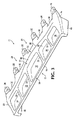
[26]本発明による図1のリップ10は、背面44において、翼部または耳部45に沿ってバケット本体8に溶接される。リップ10は、バケット本体8の対向する側壁間に延びる細長い構造を有する。本出願では、リップの細長い性質により、リップの長さは、バケットの側壁間を延びる長い寸法であると考えられるが、この寸法は、業界では、時にバケットまたはリップの幅と称される。リップは、リップ長さに沿って離間され主要リップ構造の前方向に延びる、地面係合工具を装着するための鼻部26の組を含む。リップ10は、図2から15により完全に図示される。
[26] The
[27]リップ10は、後面44を備えた後側16、前側20、および対向する端部22、24を含む。前側20は、装着部分25を画定する。横材32の前方向の装着部分25は、一揃えの離間されて置かれた鼻部26を備える。鼻部26は、中間アダプタまたは末端部(図示せず)などの地面係合工具を受け入れ、この地面係合工具は、材料を分離し、その材料を、リップを保護しながらバケット内に向ける。装着部分上の鼻部は、側板(図示せず)などの追加の地面係合工具を取り付けるための装着領域30によって分離される。リップ10は、好ましくは鋳造リップであるが、これは、一緒に溶接された部分(好ましくは鋳造部分)から形成されてよい。
[27] The
[28]図示される実施形態では、リップ10は、前側20が中心に向かって前方向に階段状にされるような階段状リップであり、それにより、鼻部26は、リップの中心に近くなるほど、端部22、24に近いこれらの鼻部よりさらに前方向にあり、このとき、鼻部間の部分は、リップの長さに全般的に沿って延びている。そうではあるが、本発明によるリップは、鼻部間の中間部分がリップの長さに対して傾斜したスペード構成、または逆向きの階段状もしくは逆スペード構成を有することができる。さらに、リップ10は、前面図において線形として示されているが、その長さにわたって弓曲状にされまたは垂直に角度付けされてよく、かつ/または上方向に湾曲する端部を含むこともできる。
[28] In the illustrated embodiment, the
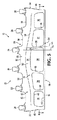
[29]リップの支持構造体28は、装着部分25の後方向にあり、これを支持する。支持構造体28は、掘り出し作業中に遭遇するあらゆる種類の負荷、ならびに回転力および曲げ力に抵抗するように形成される。本発明では、支持構造体を形成する部材は、前部横材32および後部横材34を含み、これらの横材は、その2つの横材の間に少なくとも1つの凹部を備えてリップの長さに沿って延びる。従来のリップは、掘り出し作業中、特に大きい採鉱機における非常の高い負荷に抵抗するために単一の横材構造を備えて形成される。単一の横材構造は、適切な強度および支持をもたらすが、リップは、大きくかつ重くなる傾向がある。一部の既存のリップは凹部を有するが、高い負荷に適切に対抗するのに必要とされている質量により、その重量削減は限定される。
[29] The
[30]リブ35が、好ましくは、横材32、34の間を延びて横材同士をより良好に結合させ、負荷を鼻部26からバケットに伝達する。リブは、横材間の空間を細分割して、横材32、34の間の凹部36の組を画定する。横材32、34、およびリブ35は、凹部36に沿ったリップに対してかなりの深さまたは厚さのものである。凹部は、前部横材32の後部表面40および後部横材34の前部表面42、ならびにリブ35の側部表面によって画定される。
[30]
[31]横材32および34は、寸法における大きなまたは突然の変更を有さず、端部22と24の間で全般的に連続的なものであるが、これらは、実際の端部の手前で終端することができる。横材構造体における表面的な変更は、各々の横材の主な大部分が、リップの長さに沿った全般的に連続的な中断されない延長部である限り可能である。横材は、リップにわたって延びる湾曲部を組み込むことができる。横材内の湾曲部は、好ましくは、リブの交差部と一致し湾曲によって誘発された応力集中を補償する。この全般的に連続的な中断されない構造は、リップに対して二重横材構造を与えて、凹部36の存在にも関わらず、膨れ上がる負荷および捩じれに抵抗する。横材構成におけるさまざまな変更が、本発明から逸脱することなく可能である。たとえば、横材32の深さは、端部の手前まで先細になることができる。あるいは、横材は、端部22、24からリップの中心に向かって先細になることができる。図示される実施形態では、端部22、24は、上側表面47および後部表面49において、バケットの側壁12に溶接するための翼部45を有する。翼部45は、この実施形態では、リップの主要部分の上方を延びる。
[31] The
[32]好ましくは、リップ10は、土質材料をバケット内に妨害なく投入するためにその上側表面46に沿って全般的に平滑かつ連続的である。リップの下側表面50は、横材32、34、凹部36、およびリブ35によって重量を削減するように構造化される。そうではあるが、上側表面46および下側表面50は、他の構成を有することができる。たとえば、凹部36は、好ましくは開いているが、これらは、底部を覆って、たとえば横材32、34間に溶接されたプレートによって包囲されてよい。
[32] Preferably, the
[33]リップ10の上部表面46は、前部横材32を後部横材34に結合するパネル支持構造体28Aとして考えられ得る。リブ35もまた、好ましくは、横材同士を接合させ、バケットが掘削された材料を通って前方に移動するときの軸方向力および捩じれ力に抵抗する。追加的に、1つまたは複数のパネル56が、リブ35および横材32、34に固定され、これらをリップの下面に沿って連結して凹部36を包囲する(図15)。1つのパネルまたは複数のパネルは、リップに追加の剛性をもたらし、これを支持し、また、捩じりおよび反りとして構造体の前部にかけられた側部力を吸収する。リップ構造体は、正方形のセルを備え、セルの1つの側部が構造的シートによって覆われた蜂の巣構造と考えられ得る。この構造体はまた、既存のリップの大規模な単一横材構造と比較して半張がら構造に類似する。
[33] The
[34]好ましい実施形態では、前部横材32は、リップ10内で前方向に、すなわち装着部分25のすぐ後方向に配向されて、摩耗部分により大きい強度および安定性を与える。前部横材32の前部表面38は、支持構造体25から上方向に傾斜して、横材32と地面係合工具装着体の間に円滑な移行部を画定する。横材32は、全般的に、装着部分25より大きい深さを有する。前部横材32の後部表面40は、凹状部分36に移行する。横材32の底部表面54もまた、好ましくは、掘り出し中の摩耗を低減するために後方向に傾斜するが、異なる配向を有してよい。
[34] In a preferred embodiment, the
[35]図示される実施形態は、階段状リップであるため、前部横材32は、好ましくは、中央セクション52が、端部22、24よりさらに前方向にあるように横方向に弓曲状にされる(図5)。この構造では、前部横材は、図5に示されるように全般的に連続的な前方向の弓曲部を有することができる。あるいは、前部横材は、幅広いS字形状の曲がり部の対を有して、前部横材の中央の前方向の弓曲部を画定することができる(図示せず)。この変形形態では、曲がり部は、好ましくは鼻部およびリブに全般的に沿ったものである。前部横材32は、直線のリップを有する線形になることができ、または逆スペードリップを備えて反対方向に弓曲状にされ得る。前部横材32は、前部から見たとき、リップの中心より高い端部を備えた湾曲した構成を有することができる。リップは、含まれるリップの個々の種類を問わず、所望に応じてさまざまな形状を取ることができる。
[35] Because the illustrated embodiment is a stepped lip, the
[36]後部横材34は、好ましくは、重量削減を高め、貫通性を改良し、摩耗を低減するために、そしてバケット底壁の前部に合致させるために、前部横材32に比べて低減された深さを有する。後部横材34は、凹状部分36へと上方向に傾斜する前部表面42を有する。後部表面44は、通常、翼部45の後部面49と一緒に溶接されるバケット底壁前部と合致するように略垂直であるが、リップをバケットに取り付けるための溶接材料を受け入れる面取り部などの特徴を含むことができる。後部横材34は、好ましくは、底壁への溶接に対応するために線形であるが、他の底壁形状への取り付けを容易にするために非線形になることができる。
[36] The
[37]リブ35は、リップの強度および剛性を増大させるために前部横材32と後部横材34の間を横方向(すなわち前から後ろ)に延びる。リブ35は、前部横材32の後部表面40および後部横材34の前部表面42と交差する比較的薄い支持体である。好ましくは、リブ35は、前部横材32のより大きい深さから後部横材34のより小さい深さまで除々に傾斜するように深さにおいて後ろ方向に先細になる。リブのこの先細部は、重量を低減し、貫通性を改良し、摩耗を減じる。図4に見られるように、リブ35は、好ましくは、曲げモーメントを後部横材34に最適に伝達するために鼻部26の後方で中心揃えされるが、これらは、他の位置を有することができ、または他の位置に追加のリブが設けられてよい。リブ35は、これらが前部横材から後部横材まで延びるにつれてリップ端部22、24に向かって外方向にそれることができるが、これらは、互いに平行になることができ、または後ろ方向に互いに近寄ることができる。それたリブは、かけられた負荷をバケットに分散させるので、リップ内の応力を低減する。横方向軸TAは、リップ前部からリップの後部まで後部横材44に対して垂直に延び、リブは、長手方向のリブ軸RAを画定する。図示される実施形態では、リブ軸は、少なくとも5度の角度αでリップ軸に対して傾斜する。代替の実施形態では、リブ35の副組は、前部横材から後部横材まで延びるにつれて外方向にそれ、リブの残りはそれない。
[37]
[38]支持構造体28の構成はまた、リブ35が、装着部分25の鼻部26の幅より狭くなることを可能にする。従来のリップは、これらが支持する鼻部の幅を超える幅を有する大きなリブを有する。リップの質量を大きく低減するようにして前部および後部の横材の適切な支持および結合をもたらすことができる狭いリブを使用する。そうではあるが、リブは、(たとえば、鼻部の軸に平行に、逆方向に傾斜してなどの)他の配向を有することができ、略線形以外にも他の形状を有することができる。また、この実施形態では、翼部45もまた、端部22、24において横材32、34間を延び、部分的にリブ35と同じように機能する。翼部およびリブは、総合的に、横方向支持体と称される。
[38] The configuration of the
[39]横材32と34の間の凹状部分36は、隣接する支持部材より薄く、リップの大きい部分を占める。図示される例では、凹部は、リブ35および翼部45以外の、横材32、34間の部分全体を画定する。見られ得るように、リップは、横材32、34のいずれのものよりかなり低減された厚さ(または深さ)を有する。この例では、凹部の中心は、前部横材32の中心にある深さの25%未満である深さを有する。同様に、凹部の中心にある厚さ(または深さ)は、後部横材34の中心にある厚さの約50%である。当然ながら、他の相対的厚さが使用され得る。凹部36は、厚さにおいて縁部から中心にかけて先細になるようにドーム型にされ得る。
[39] The
[40]支持構造体28の凹部は、所望の重量削減を達成するために、リップのかなりの部分を構成する。本発明の特定の好ましい実施形態では、重量削減は、従来のリップを超えて最大限にされ得る。たとえば、これらの特定の好ましい実施形態では、リップ内の凹部の合計の総合容積は、凹部の容積を含むリップの合計容積の少なくとも約15%である。1つの好ましい実施形態では、凹部の容積は、リップの合計容積の約22%である。たとえば、リップの合計容積は、約0.731立方メートルであり、凹部の合計の総合容積は、約0.163立方メートルである。本発明のリップは、当然ながら、数多くの異なるサイズおよびタイプのリップにおいて使用され得る。比較として、匹敵するサイズの1つの従来のリップでは、凹部の容積は、(凹部の容積を含む)リップの合計容積の約12%である。たとえば、従来のリップの容積が0.80立方メートルの場合、凹部の容積は、約0.099立方メートルである。他の従来のリップでは、凹部の容積は、7.3%から14.1%の範囲である。従来のリップは、本発明の最大限の重量削減構造を有さず、所望の強度を維持するのにより多くの質量および少ない凹部を必要とする。本発明は、凹部の合計の総合容積が、(凹部の容積を含む)リップの合計容積の少なくとも15%であることに依存しない。一部の使用およびサイズにおいては、本発明によるリップ(たとえば1つまたは複数の凹部によって分離された前部および後部の横材を備えたリップ)は、凹部の合計の総合容積が、(凹部の容積を含む)リップの合計容積の15%をかなり下回る構造を有することができる。
[40] The recesses in the
[41]大きく低減された厚さによって主に画定された凹状部分36の両側に離間されて置かれた横材32、34の対を使用するこの有利な構造は、リップ内の重量を大幅に削減する。1つの例では、6803.886キログラム(15000ポンド)のリップに対する重量削減は、約544.311キログラム(1200ポンド)である。全般的には、重量削減は約2〜12%であると予想されるが、従来のリップをより上回るものになることができる。リップのサイズおよび機械のタイプに応じて、大なり小なりの重量の削減が可能である。
[41] This advantageous construction using pairs of
Claims (56)
前記リップは、
前側および後側であって、前記前側は地面係合工具を取り付け可能な装着部分を含む、前側および後側と、
前記リップの前記長さの大部分に沿って延びて使用中の負荷に対して抵抗をもたらす前部横材および後部横材であって、それぞれが連続して突然の変更を有さず、前記リップの長さに実質上沿って延び、前記前部横材は前記装着部分に隣接して後方に位置し、前記前部横材は上下方向について前記装着部材および前記後部横材の厚さよりも大きな厚さを有し、前記後部横材は前記後側に沿っている、前部横材および後部横材と、
前記前部および後部の横材を一緒に結合し、前記バケット内へと土質材料がその上を通過する上部表面を画定する上部パネルと、
前記前部および後部横材間を相互連結し、渡す複数のリブと、を備え、
前記装着部材、前記前部横材および後部横材、前記上部パネル並びに前記リブの少なくとも一部分は、前記少なくとも1つの鋳造体に形成され、
前記前部および後部横材は前記上部パネルより厚く、前記リブに沿って、前記上部パネル下方の、前記前部および後部の横材間に凹部を画定し、各々の前記凹部は前記上部パネルから離間する方向に開口する、リップ。 Rutotomoni comprising at least one casting, having a length extending between opposite sidewalls of the bucket, a lip for the bucket,
The lip is
A front side and a rear side, the front side including a mounting portion to which a ground engaging tool can be attached;
A front crosspiece and a back crosspiece that extend along most of the length of the lip and provide resistance to loads in use, each without a series of sudden changes, Extending substantially along the length of the lip, the front crosspiece positioned rearward adjacent to the mounting portion, the front crosspiece being vertically above the thickness of the mounting member and the rear crosspiece A front cross member and a rear cross member having a large thickness, the rear cross member being along the rear side;
An upper panel that joins the front and rear cross members together and defines an upper surface over which the soil material passes into the bucket;
A plurality of ribs interconnecting and passing between the front and rear cross members,
At least a portion of the mounting member, the front cross member and the rear cross member, the upper panel and the rib are formed in the at least one cast body,
The front and rear cross members are thicker than the upper panel, and define a recess between the front and rear cross members below the upper panel along the rib, and each of the recesses extends from the upper panel. A lip that opens in the direction of separation.
前記リップは、少なくとも1つの鋳造体によって画定され、
前側および後側であって、前記前側は地面係合工具を取り付け可能な装着部分を含む、前側および後側と、
前記リップの前記長さの大部分に沿って延びて使用中の負荷に対して抵抗をもたらす前部横材および後部横材であって、それぞれが連続して突然の変更を有さず、前記リップの長さに実質上沿って延び、前記前部横材は前記装着部分に隣接して後方に位置し、前記前部横材は上下方向について前記装着部材および前記後部横材の厚さよりも大きな厚さを有し、前記後部横材は前記後側に沿っている、前部横材および後部横材と、
前記前部および後部横材を一緒に結合し、前記バケット内へと土質材料がその上を通過する上部表面を画定する上部パネルと、
前記前部および後部横材間を相互連結し、渡す複数のリブと、を備え、
前記装着部材、前記前部横材および後部横材、前記上部パネル並びに前記リブの少なくとも一部分は、前記少なくとも1つの鋳造体に形成され、
前記前部および後部横材は前記上部パネルより厚く、前記上部パネル下方の、前記前部および後部の横材間に複数の凹部を画定し、各々の前記凹部は前記上部パネルから離間する方向に開口する、掘削バケット。 During digging work, a wall comprising a side wall defining a cavity for receiving the soil material, provided with a lip having a length extending between opposite sidewalls of the bucket, a drilling bucket,
The lip is defined by at least one casting;
A front side and a rear side, the front side including a mounting portion to which a ground engaging tool can be attached;
A front cross member and a rear cross member that provides resistance to loads in use extends along most of the length of the lip, no sudden changes respectively to continue communication, Extending substantially along the length of the lip, the front cross member is positioned rearward adjacent to the mounting portion, and the front cross member is in the vertical direction from the thickness of the mounting member and the rear cross member. The rear cross member is along the rear side , the front cross member and the rear cross member,
An upper panel that joins the front and rear crosspieces together and defines an upper surface over which soil material passes into the bucket;
A plurality of ribs interconnecting and passing between the front and rear cross members,
At least a portion of the mounting member, the front cross member and the rear cross member, the upper panel and the rib are formed in the at least one cast body,
The front and rear cross members are thicker than the upper panel, and a plurality of recesses are defined between the front and rear cross members below the upper panel, and each of the recesses is separated from the upper panel. A drilling bucket that opens .
含む、請求項21に記載の掘削バケット。22. A drilling bucket according to claim 21 comprising.
前記リップは、The lip is
前記リップの前記長さに実質的に沿って延びて使用中の負荷に対して支持をもたらす前部横材および後部横材であって、前記前部および後部横材のそれぞれは連続して突然の変更を有さず、前記リップの全長に実質上沿った方向に延びる、前部横材および後部横材と、A front crosspiece and a back crosspiece extending substantially along the length of the lip to provide support for loads in use, each of the front and rear crosspieces being abrupt in succession A front crosspiece and a rear crosspiece extending in a direction substantially along the entire length of the lip,
地面係合工具を支持するために、前記前部横材の前方で、前方に突出する複数の鼻部と、A plurality of noses protruding forward in front of the front cross member to support a ground engaging tool;
前記前部および後部横材を一緒に結合し、前記バケット内へと土質材料がその上を通過する上部表面を画定する上部パネルと、An upper panel that joins the front and rear crosspieces together and defines an upper surface over which soil material passes into the bucket;
前記前部および後部横材間を延びる複数のリブと、を備え、A plurality of ribs extending between the front and rear cross members,
前記前部および後部横材は前記上部パネルより厚く、前記リブに沿って、前記上部パネル下方の、前記前部および後部の横材間に凹部を画定し、各々の前記リブは前記鼻部の1つと全般的に位置合わせ状態にある、リップ。The front and rear crosspieces are thicker than the top panel, and define a recess along the rib between the front and rear crosspieces below the top panel, each rib of the nose A lip that is generally aligned with one.
前記リップは、
前記リップの長さの少なくとも大部分に沿って途切れることなく延びる前部横材および後部横材と、
前記前部および後部横材間を延び、前記バケット内へと土質材料がその上を通過する上部表面を画定する上部パネルと、
歯部を取り付けるための前方に突出する複数の鼻部と、前記鼻部の間に側板を取り付けるための複数の装着領域とを含み、前記バケットの前方に延びる装着構造と、
前記上部パネルの下方で前記前部および後部横材間を延びるリブと、
前記リブに沿って前記前部および後部横材間に画定された複数の凹部と、を含み、
前記リップは前記前部横材から前後方向について厚みが先細りする、リップ。 A lip for a drilling bucket , defined by at least one casting and having a length extending between sidewalls of the bucket,
The lip is
A front crosspiece and a rear crosspiece extending uninterrupted along at least most of the length of the lip;
An upper panel extending between the front and rear crosspieces and defining an upper surface over which soil material passes into the bucket;
A mounting structure including a plurality of nose portions projecting forward for attaching a tooth portion, and a plurality of mounting regions for attaching a side plate between the nose portions, and extending forward of the bucket;
A rib extending between the front and rear crosspieces below the upper panel;
Look including a plurality of recesses defined between the front and rear cross member along said rib,
The lip has a thickness that tapers in the front-rear direction from the front cross member .
前記リップは、The lip is
前記リップの前記長さに沿って延びて使用中の負荷に対して抵抗をもたらす前部横材および後部横材であって、前記前部および後部横材のそれぞれは連続して突然の変更を有さず、前記リップの全長に実質上沿って延びる、前部横材および後部横材と、A front crosspiece and a back crosspiece that extend along the length of the lip and provide resistance to a load in use, each of the front and rear crosspieces being continuously and suddenly changed. A front cross piece and a rear cross piece extending substantially along the entire length of the lip,
地面係合工具を支持するために、前記前部横材の前方で、前方に突出する複数の鼻部と、A plurality of noses protruding forward in front of the front cross member to support a ground engaging tool;
前記前部および後部横材を一緒に結合し、前記バケット内へと土質材料がその上を通過する上部表面を画定する上部パネルと、An upper panel that joins the front and rear crosspieces together and defines an upper surface over which soil material passes into the bucket;
前記前部および後部横材間を延びる複数のリブと、を備え、A plurality of ribs extending between the front and rear cross members,
前記前部および後部横材は前記上部パネルより厚く、前記リブに沿って、前記上部パネル下方の、前記前部および後部の横材間に凹部を画定し、各々の前記リブは前記鼻部の1つと全般的に位置合わせ状態にある、掘削バケット。The front and rear crosspieces are thicker than the top panel, and define a recess along the rib between the front and rear crosspieces below the top panel, each rib of the nose Excavation bucket in general alignment with one.
前記リップは、The lip is
前記鋳造体の長さの少なくとも大部分に沿って途切れることなく延びる前部横材および後部横材と、A front cross member and a rear cross member that extend without interruption along at least a major portion of the length of the casting;
前記前部および後部横材間を延び、前記バケット内へと土質材料がその上を通過する上部表面を画定する上部パネルと、An upper panel extending between the front and rear crosspieces and defining an upper surface over which soil material passes into the bucket;
歯部を取り付けるための前方に突出する複数の鼻部と、前記鼻部の間に側板を取り付けるための複数の装着領域とを含み、前記バケットの前方に延びる装着構造と、A mounting structure including a plurality of nose portions projecting forward for attaching a tooth portion, and a plurality of mounting regions for attaching a side plate between the nose portions, and extending forward of the bucket;
前記上部パネルの下方で前記前部および後部横材間を延びるリブと、A rib extending between the front and rear crosspieces below the upper panel;
前記リブに沿って前記前部および後部横材間に画定された複数の凹部と、を含み、A plurality of recesses defined between the front and rear cross members along the rib, and
前記リップは前記前部横材から前後方向について厚みが先細りする、掘削バケット。The lip is a drilling bucket whose thickness tapers in the front-rear direction from the front cross member.
前記リップの前記長さに連続的で実質的に沿って延びて使用中の負荷に対して支持をもたらす前部横材および後部横材であって、前記前部横材は、上下方向について前記後部横材よりも厚い、前部横材および後部横材と、A front crosspiece and a rear crosspiece that extend continuously and substantially along the length of the lip to provide support for loads in use, the front crosspiece being A front crosspiece and a back crosspiece, thicker than the back crosspiece,
地面係合工具を支持するために、前記前部横材の前方で、前方に突出する複数の鼻部と、A plurality of noses protruding forward in front of the front cross member to support a ground engaging tool;
前記前部および後部横材を一緒に結合し、前記バケット内へと土質材料がその上を通過する上部表面を画定する上部パネルと、An upper panel that joins the front and rear crosspieces together and defines an upper surface over which soil material passes into the bucket;
前記前部および後部横材間を延びる複数のリブと、を備え、A plurality of ribs extending between the front and rear cross members,
前記前部および後部横材は前記上部パネルより厚く、前記リブに沿って、前記上部パネル下方の、前記前部および後部の横材間に凹部を画定し、前記凹部は、総合的には、凹部の合計の総合容積を含む前記リップの合計容積の少なくとも15パーセントである、リップ。The front and rear cross members are thicker than the upper panel, and define a recess between the front and rear cross members below the upper panel along the ribs. A lip that is at least 15 percent of the total volume of the lip including the total combined volume of the recesses.
前記リップは、The lip is
前記リップの前記長さに連続的で実質的に沿って延びて使用中の負荷に対して支持をもたらす前部横材および後部横材であって、前記前部横材は、上下方向について前記後部横材よりも厚い、前部横材および後部横材と、A front crosspiece and a rear crosspiece that extend continuously and substantially along the length of the lip to provide support for loads in use, the front crosspiece being A front crosspiece and a back crosspiece, thicker than the back crosspiece,
地面係合工具を支持するために、前記前部横材の前方で、前方に突出する複数の鼻部と、A plurality of noses protruding forward in front of the front cross member to support a ground engaging tool;
前記前部および後部横材を一緒に結合し、前記バケット内へと土質材料がその上を通過する上部表面を画定する上部パネルと、An upper panel that joins the front and rear crosspieces together and defines an upper surface over which soil material passes into the bucket;
前記前部および後部横材間を延びる複数のリブと、を備え、A plurality of ribs extending between the front and rear cross members,
前記前部および後部横材は前記上部パネルより厚く、前記リブに沿って、前記上部パネル下方の、前記前部および後部の横材間に凹部を画定し、凹部は、総合的には、凹部の合計の総合容積を含む前記リップの合計容積の少なくとも15パーセントである、掘削バケット。The front and rear cross members are thicker than the upper panel, and define a recess between the front and rear cross members below the upper panel along the rib. The recess is generally a recess. A drilling bucket that is at least 15 percent of the total volume of the lip, including the total combined volume of
Applications Claiming Priority (3)
| Application Number | Priority Date | Filing Date | Title |
|---|---|---|---|
| US201261654501P | 2012-06-01 | 2012-06-01 | |
| US61/654,501 | 2012-06-01 | ||
| PCT/US2013/043428 WO2013181435A1 (en) | 2012-06-01 | 2013-05-30 | Lip for excavating bucket |
Publications (3)
| Publication Number | Publication Date |
|---|---|
| JP2015518100A JP2015518100A (en) | 2015-06-25 |
| JP2015518100A5 JP2015518100A5 (en) | 2016-07-07 |
| JP6333808B2 true JP6333808B2 (en) | 2018-05-30 |
Family
ID=49668521
Family Applications (1)
| Application Number | Title | Priority Date | Filing Date |
|---|---|---|---|
| JP2015515199A Active JP6333808B2 (en) | 2012-06-01 | 2013-05-30 | Lip for drilling bucket |
Country Status (23)
| Country | Link |
|---|---|
| US (3) | US9963853B2 (en) |
| EP (2) | EP3461956B1 (en) |
| JP (1) | JP6333808B2 (en) |
| KR (1) | KR102059872B1 (en) |
| CN (1) | CN104487636B (en) |
| AR (2) | AR091258A1 (en) |
| AU (2) | AU2013267345B2 (en) |
| CA (1) | CA2874119C (en) |
| CY (1) | CY1120955T1 (en) |
| DK (1) | DK2855785T3 (en) |
| EA (2) | EA031794B1 (en) |
| ES (1) | ES2701999T3 (en) |
| HR (1) | HRP20181959T1 (en) |
| HU (1) | HUE041233T2 (en) |
| IN (1) | IN2014DN10028A (en) |
| LT (1) | LT2855785T (en) |
| PL (1) | PL2855785T3 (en) |
| PT (1) | PT2855785T (en) |
| RS (1) | RS58247B1 (en) |
| SI (1) | SI2855785T1 (en) |
| TR (1) | TR201818765T4 (en) |
| WO (1) | WO2013181435A1 (en) |
| ZA (1) | ZA202102050B (en) |
Families Citing this family (31)
| Publication number | Priority date | Publication date | Assignee | Title |
|---|---|---|---|---|
| JP5318993B1 (en) * | 2012-05-29 | 2013-10-16 | 株式会社小松製作所 | Construction machinery excavation bucket |
| USD767647S1 (en) | 2015-04-17 | 2016-09-27 | Caterpillar Inc. | Lip shroud for ground engaging machine implement |
| US9957696B2 (en) | 2015-04-17 | 2018-05-01 | Caterpillar Inc. | Tool retention system |
| US9951500B2 (en) | 2015-04-17 | 2018-04-24 | Caterpillar Inc. | Tool retention system |
| USD766994S1 (en) | 2015-04-17 | 2016-09-20 | Caterpillar Inc. | Wing shroud for ground engaging machine implement |
| US9970181B2 (en) | 2015-04-17 | 2018-05-15 | Caterpillar Inc. | Lip for machine bucket |
| USD769946S1 (en) | 2015-04-17 | 2016-10-25 | Caterpillar Inc. | Lip for ground engaging machine implement |
| CN105275045A (en) * | 2015-11-11 | 2016-01-27 | 太原重工股份有限公司 | Bucket and bucket lip thereof |
| USD797162S1 (en) | 2016-07-21 | 2017-09-12 | Caterpillar Inc. | Lip for ground engaging machine implement and/or digital representation thereof |
| USD797163S1 (en) | 2016-07-21 | 2017-09-12 | Caterpillar Inc. | Lip shroud for ground engaging machine implement and/or digital representation thereof |
| US10480162B2 (en) * | 2016-12-15 | 2019-11-19 | Caterpillar Inc. | Implement ground engaging tip assembly having tip with tapered retention channel |
| US10544562B2 (en) * | 2017-04-21 | 2020-01-28 | Caterpillar Inc. | Dragline bucket |
| USD842345S1 (en) | 2017-07-21 | 2019-03-05 | Caterpillar Inc. | Lip shroud for a ground engaging machine implement |
| EP3660232A1 (en) * | 2017-07-27 | 2020-06-03 | Metalogenia Research & Technologies S.L. | Lip of a scoop for earth-moving machines |
| US10737297B2 (en) * | 2017-08-21 | 2020-08-11 | Cnh Industrial America Llc | Stone sieve apparatus |
| USD832309S1 (en) | 2017-08-30 | 2018-10-30 | Caterpillar Inc. | Lip shroud for a ground engaging machine implement |
| USD842346S1 (en) | 2017-10-11 | 2019-03-05 | Caterpillar Inc. | Shroud for a ground engaging machine implement |
| USD842347S1 (en) | 2017-10-11 | 2019-03-05 | Caterpillar Inc. | Shroud for a ground engaging machine implement |
| USD873306S1 (en) | 2018-10-03 | 2020-01-21 | Caterpillar Inc. | Bucket shroud |
| USD882644S1 (en) | 2018-10-03 | 2020-04-28 | Caterpillar Inc. | Bucket shroud |
| USD882645S1 (en) | 2018-10-03 | 2020-04-28 | Caterpillar Inc. | Bucket shroud |
| USD882646S1 (en) | 2018-11-09 | 2020-04-28 | Caterpillar Inc. | Bucket shroud |
| EP3947833A4 (en) * | 2019-03-27 | 2022-12-28 | ESCO Group LLC | Lip for excavating bucket |
| US11492784B2 (en) | 2019-04-15 | 2022-11-08 | Hensley Industries, Inc. | Position-biased locking pin assembly for a ground engaging wear member |
| USD927561S1 (en) | 2019-10-04 | 2021-08-10 | Caterpillar Inc. | Bucket shroud |
| USD928849S1 (en) * | 2019-10-04 | 2021-08-24 | Caterpillar Inc. | Bucket shroud |
| USD928848S1 (en) * | 2019-10-04 | 2021-08-24 | Caterpillar Inc. | Bucket shroud |
| US11634892B2 (en) | 2019-11-27 | 2023-04-25 | Hensley Industries, Inc. | Excavating tooth assembly with releasable lock pin assembly |
| USD959505S1 (en) | 2021-03-25 | 2022-08-02 | Caterpillar Inc. | Bucket shroud |
| USD978923S1 (en) | 2021-06-03 | 2023-02-21 | Caterpillar Inc. | Bucket shroud |
| US12054921B2 (en) | 2021-06-03 | 2024-08-06 | Caterpillar Inc. | Corner guard for a work implement assembly |
Family Cites Families (52)
| Publication number | Priority date | Publication date | Assignee | Title |
|---|---|---|---|---|
| US1208054A (en) | 1915-12-10 | 1916-12-12 | American Manganese Steel Co | Dipper-front. |
| US1453813A (en) * | 1920-10-29 | 1923-05-01 | American Manganese Steel Co | Dipper front |
| US1582577A (en) | 1925-08-24 | 1926-04-27 | Pettibone Mulliken Company | Dipper bucket |
| US1642189A (en) | 1925-09-02 | 1927-09-13 | William M Bager | Dipper for excavating machinery |
| US1921491A (en) | 1930-06-25 | 1933-08-08 | Lesher W Van Buskirk | Power shovel dipper |
| US1959847A (en) * | 1931-07-31 | 1934-05-22 | Lesher W Van Buskirk | Dipper construction and the like |
| US1920703A (en) * | 1931-08-28 | 1933-08-01 | Pettibone Mulliken Company | Dipper front |
| US1908883A (en) | 1932-06-20 | 1933-05-16 | Pettibone Mulliken Company | Dipper |
| US1914104A (en) * | 1932-08-25 | 1933-06-13 | Pettibone Mulliken Company | Dipper construction |
| US2091974A (en) | 1936-03-16 | 1937-09-07 | Bucyrus Erie Co | Excavating dipper |
| US2427897A (en) * | 1945-08-27 | 1947-09-23 | Harnischfeger Corp | Excavator dipper construction |
| US2874491A (en) * | 1953-12-31 | 1959-02-24 | Electric Steel Foundry Co | Bucket tooth assembly |
| US2926800A (en) * | 1957-09-16 | 1960-03-01 | Electric Steel Foundry Co | All-cast dipper |
| US3107445A (en) | 1961-09-25 | 1963-10-22 | American Brake Shoe Co | Power shovel dipper |
| US3307277A (en) * | 1963-11-04 | 1967-03-07 | Kondracki Joseph | Bucket attachment |
| US3851413A (en) | 1971-08-23 | 1974-12-03 | Caterpillar Tractor Co | Quick change cutting edge |
| US4129952A (en) * | 1977-10-27 | 1978-12-19 | Caterpillar Tractor Co. | Wear strips for earthmoving buckets |
| US4238896A (en) | 1979-08-24 | 1980-12-16 | Caterpillar Tractor Co. | Cutting edge assembly for a loader bucket |
| SE445125B (en) | 1981-03-26 | 1986-06-02 | Bofors Ab | SOIL WORKING MACHINERY SYSTEM |
| US4407081A (en) | 1981-12-07 | 1983-10-04 | J. I. Case Company | Bucket tooth attachment means |
| US4570365A (en) | 1983-11-23 | 1986-02-18 | Bierwith Robert S | Digging tooth and bucket lip construction |
| DE3611493A1 (en) | 1986-04-05 | 1987-10-15 | Orenstein & Koppel Ag | Digging shovel for excavators |
| US5016365A (en) | 1989-06-06 | 1991-05-21 | Gh Hensley Industries, Inc. | Wear parts for excavation apparatus |
| US5077918A (en) | 1990-09-10 | 1992-01-07 | Caterpillar Inc. | Cutting edge assembly for an implement |
| US5412885A (en) | 1993-07-02 | 1995-05-09 | Caterpillar Inc. | Bucket base edge protector assembly |
| US5526592A (en) | 1994-07-22 | 1996-06-18 | Bierwith; Robert S. | Tooth assembly for excavation bucket |
| US5553409A (en) | 1995-08-22 | 1996-09-10 | Foothills Steel Foundry Ltd. | Shroud anchor system |
| US5713145A (en) | 1996-03-12 | 1998-02-03 | Gh Hensley Industries, Inc. | Wear resistant excavating apparatus |
| US5852888A (en) | 1996-11-08 | 1998-12-29 | Caterpillar Inc. | Apparatus for protecting a base of a bucket of an earth working machine |
| JPH10338944A (en) * | 1997-06-06 | 1998-12-22 | Komatsu Ltd | Bucket |
| WO1999023316A1 (en) | 1997-10-30 | 1999-05-14 | Bierwith Robert S | Bucket assembly with an improved lip |
| US5901480A (en) | 1997-12-18 | 1999-05-11 | G.H. Hensley Industries, Inc. | Reinforced loader bucket structure |
| USD478599S1 (en) | 2000-08-31 | 2003-08-19 | Caterpillar Sarl | Lip for an excavation bucket |
| US6990760B1 (en) | 2000-09-14 | 2006-01-31 | Caterpillar Sarl | Lip for an excavation bucket |
| US6240663B1 (en) | 2000-09-18 | 2001-06-05 | G. H. Hensley Industries, Incorporated | Streamlined resilient connection system for attaching a wear member to an excavating lip structure |
| US6751897B2 (en) | 2000-11-27 | 2004-06-22 | Robert S. Bierwith | Lip assembly |
| US6668472B2 (en) | 2001-07-16 | 2003-12-30 | Robert Bierwith | Wedge-locking system and excavation bucket assembly with wedge-locking system |
| AUPR803301A0 (en) | 2001-10-02 | 2001-10-25 | Meyers, Thomas Anthony | Excavator bucket |
| AUPR803401A0 (en) | 2001-10-02 | 2001-10-25 | Meyers, Thomas Anthony | Excavator teeth |
| US7266914B2 (en) * | 2001-10-09 | 2007-09-11 | Peninsula Alloy Inc. | Wear plate assembly |
| US7080470B2 (en) * | 2003-04-30 | 2006-07-25 | Esco Corporation | Wear assembly for excavator digging edge |
| US6986216B2 (en) | 2003-04-30 | 2006-01-17 | Esco Corporation | Wear assembly for the digging edge of an excavator |
| CA2501697C (en) * | 2004-04-23 | 2012-07-31 | Robert S. Bierwith | Lip assembly including side portions with projections |
| USD537846S1 (en) | 2005-12-20 | 2007-03-06 | Caterpillar Inc. | Bucket cutting edge |
| KR101618022B1 (en) | 2007-05-10 | 2016-05-03 | 에스코 코포레이션 | Wear assembly for excavating equipment |
| AU2007240241B1 (en) * | 2007-12-12 | 2008-09-18 | Swift Assets Pty Ltd | An Excavator Bucket |
| US20100005689A1 (en) | 2008-07-10 | 2010-01-14 | Cqms Pty Ltd | Heavy duty excavator bucket |
| WO2010049546A1 (en) | 2008-10-29 | 2010-05-06 | Metalogenia, S.A. | System for protecting the scoop of an earth-moving machine or the like and components |
| AU332139S (en) | 2009-12-11 | 2010-08-09 | Cqms Pty Ltd | An excavator lip |
| CA2785244A1 (en) * | 2009-12-24 | 2011-06-30 | Cqms Pty Ltd | A wear assembly for an excavator bucket |
| JP2012002011A (en) * | 2010-06-18 | 2012-01-05 | Chubu Electric Power Co Inc | Shovel bucket |
| US9840828B2 (en) * | 2011-05-24 | 2017-12-12 | Robert S. Bierwith | Container lip for excavating equipment providing improved material flow over lip |
-
2013
- 2013-05-30 RS RS20181466A patent/RS58247B1/en unknown
- 2013-05-30 WO PCT/US2013/043428 patent/WO2013181435A1/en active Application Filing
- 2013-05-30 DK DK13796346.8T patent/DK2855785T3/en active
- 2013-05-30 US US13/906,085 patent/US9963853B2/en active Active
- 2013-05-30 PL PL13796346T patent/PL2855785T3/en unknown
- 2013-05-30 HU HUE13796346A patent/HUE041233T2/en unknown
- 2013-05-30 JP JP2015515199A patent/JP6333808B2/en active Active
- 2013-05-30 PT PT13796346T patent/PT2855785T/en unknown
- 2013-05-30 SI SI201331269T patent/SI2855785T1/en unknown
- 2013-05-30 EP EP18196295.2A patent/EP3461956B1/en active Active
- 2013-05-30 CA CA2874119A patent/CA2874119C/en active Active
- 2013-05-30 CN CN201380036260.8A patent/CN104487636B/en active Active
- 2013-05-30 ES ES13796346T patent/ES2701999T3/en active Active
- 2013-05-30 EP EP13796346.8A patent/EP2855785B1/en active Active
- 2013-05-30 KR KR1020147035394A patent/KR102059872B1/en active IP Right Grant
- 2013-05-30 EA EA201401329A patent/EA031794B1/en unknown
- 2013-05-30 TR TR2018/18765T patent/TR201818765T4/en unknown
- 2013-05-30 IN IN10028DEN2014 patent/IN2014DN10028A/en unknown
- 2013-05-30 LT LTEP13796346.8T patent/LT2855785T/en unknown
- 2013-05-30 AU AU2013267345A patent/AU2013267345B2/en active Active
- 2013-05-30 EA EA201891156A patent/EA036908B1/en unknown
- 2013-06-03 AR ARP130101955 patent/AR091258A1/en active IP Right Grant
-
2017
- 2017-10-17 AU AU2017248454A patent/AU2017248454B2/en active Active
- 2017-12-07 US US15/834,557 patent/US10774499B2/en active Active
-
2018
- 2018-11-22 HR HRP20181959TT patent/HRP20181959T1/en unknown
- 2018-12-03 CY CY181101282T patent/CY1120955T1/en unknown
-
2019
- 2019-10-24 AR ARP190103068A patent/AR116840A2/en active IP Right Grant
-
2020
- 2020-08-10 US US16/988,930 patent/US20200370271A1/en active Pending
-
2021
- 2021-03-26 ZA ZA2021/02050A patent/ZA202102050B/en unknown
Also Published As
Similar Documents
| Publication | Publication Date | Title |
|---|---|---|
| JP6333808B2 (en) | Lip for drilling bucket | |
| RU2646260C2 (en) | Excavator bucket and earth-moving machine | |
| US9428881B1 (en) | Bucket with multi-component wrapper | |
| CN108625427B (en) | Bucket for implement system having symmetrical tooth mounting members | |
| US7810581B2 (en) | Blade apparatus for work machine and work machine having the same | |
| CN103562466B (en) | Excavator bucket for construction machinery | |
| CN103958791B (en) | Excavator bucket for construction machinery | |
| CA2775868C (en) | Straight taper dipper | |
| KR102360921B1 (en) | Bucket for excavator | |
| AU2015203529B2 (en) | Heavy duty excavator bucket | |
| KR100666435B1 (en) | Bucket for construction machine | |
| CN111910698B (en) | Bucket | |
| CN214574224U (en) | Trimming shovel and continuous wall grab bucket machine | |
| CN213653591U (en) | High-efficient broken ground bucket tooth | |
| CN215715625U (en) | Bucket structure and engineering machinery | |
| CN211665841U (en) | Excavator bucket tooth and excavator | |
| AU2015202548B2 (en) | A dipper |
Legal Events
| Date | Code | Title | Description |
|---|---|---|---|
| A521 | Request for written amendment filed |
Free format text: JAPANESE INTERMEDIATE CODE: A523 Effective date: 20160520 |
|
| A621 | Written request for application examination |
Free format text: JAPANESE INTERMEDIATE CODE: A621 Effective date: 20160520 |
|
| A977 | Report on retrieval |
Free format text: JAPANESE INTERMEDIATE CODE: A971007 Effective date: 20170206 |
|
| A131 | Notification of reasons for refusal |
Free format text: JAPANESE INTERMEDIATE CODE: A131 Effective date: 20170404 |
|
| A601 | Written request for extension of time |
Free format text: JAPANESE INTERMEDIATE CODE: A601 Effective date: 20170703 |
|
| A521 | Request for written amendment filed |
Free format text: JAPANESE INTERMEDIATE CODE: A523 Effective date: 20171003 |
|
| TRDD | Decision of grant or rejection written | ||
| A01 | Written decision to grant a patent or to grant a registration (utility model) |
Free format text: JAPANESE INTERMEDIATE CODE: A01 Effective date: 20180327 |
|
| A61 | First payment of annual fees (during grant procedure) |
Free format text: JAPANESE INTERMEDIATE CODE: A61 Effective date: 20180425 |
|
| R150 | Certificate of patent or registration of utility model |
Ref document number: 6333808 Country of ref document: JP Free format text: JAPANESE INTERMEDIATE CODE: R150 |
|
| S111 | Request for change of ownership or part of ownership |
Free format text: JAPANESE INTERMEDIATE CODE: R313111 |
|
| R350 | Written notification of registration of transfer |
Free format text: JAPANESE INTERMEDIATE CODE: R350 |
|
| R250 | Receipt of annual fees |
Free format text: JAPANESE INTERMEDIATE CODE: R250 |
|
| R250 | Receipt of annual fees |
Free format text: JAPANESE INTERMEDIATE CODE: R250 |
|
| R250 | Receipt of annual fees |
Free format text: JAPANESE INTERMEDIATE CODE: R250 |
|
| R250 | Receipt of annual fees |
Free format text: JAPANESE INTERMEDIATE CODE: R250 |