US1908883A - Dipper - Google Patents
Dipper Download PDFInfo
- Publication number
- US1908883A US1908883A US618389A US61838932A US1908883A US 1908883 A US1908883 A US 1908883A US 618389 A US618389 A US 618389A US 61838932 A US61838932 A US 61838932A US 1908883 A US1908883 A US 1908883A
- Authority
- US
- United States
- Prior art keywords
- section
- body section
- dipper
- lapping
- lip
- Prior art date
- Legal status (The legal status is an assumption and is not a legal conclusion. Google has not performed a legal analysis and makes no representation as to the accuracy of the status listed.)
- Expired - Lifetime
Links
- 238000010276 construction Methods 0.000 description 35
- 230000004048 modification Effects 0.000 description 5
- 238000012986 modification Methods 0.000 description 5
- 208000019300 CLIPPERS Diseases 0.000 description 3
- 208000021930 chronic lymphocytic inflammation with pontine perivascular enhancement responsive to steroids Diseases 0.000 description 3
- UIQWBVPFHHQZHH-UHFFFAOYSA-N OOOOOOOOOOOOOO Chemical compound OOOOOOOOOOOOOO UIQWBVPFHHQZHH-UHFFFAOYSA-N 0.000 description 2
- 229910000617 Mangalloy Inorganic materials 0.000 description 1
- MMPOTNFPDMJTRR-UHFFFAOYSA-N OOOOOOOOOOO Chemical compound OOOOOOOOOOO MMPOTNFPDMJTRR-UHFFFAOYSA-N 0.000 description 1
- 241001591024 Samea Species 0.000 description 1
- 238000005266 casting Methods 0.000 description 1
- 230000001413 cellular effect Effects 0.000 description 1
- 238000006073 displacement reaction Methods 0.000 description 1
- 229910052751 metal Inorganic materials 0.000 description 1
- 239000002184 metal Substances 0.000 description 1
- QVRVXSZKCXFBTE-UHFFFAOYSA-N n-[4-(6,7-dimethoxy-3,4-dihydro-1h-isoquinolin-2-yl)butyl]-2-(2-fluoroethoxy)-5-methylbenzamide Chemical compound C1C=2C=C(OC)C(OC)=CC=2CCN1CCCCNC(=O)C1=CC(C)=CC=C1OCCF QVRVXSZKCXFBTE-UHFFFAOYSA-N 0.000 description 1
- 230000000149 penetrating effect Effects 0.000 description 1
- 238000006467 substitution reaction Methods 0.000 description 1
Images


Classifications
-
- E—FIXED CONSTRUCTIONS
- E02—HYDRAULIC ENGINEERING; FOUNDATIONS; SOIL SHIFTING
- E02F—DREDGING; SOIL-SHIFTING
- E02F3/00—Dredgers; Soil-shifting machines
- E02F3/04—Dredgers; Soil-shifting machines mechanically-driven
- E02F3/28—Dredgers; Soil-shifting machines mechanically-driven with digging tools mounted on a dipper- or bucket-arm, i.e. there is either one arm or a pair of arms, e.g. dippers, buckets
- E02F3/36—Component parts
- E02F3/40—Dippers; Buckets ; Grab devices, e.g. manufacturing processes for buckets, form, geometry or material of buckets
Definitions
- My invention relates, more particularly, to Adippers, Vor buckets, for use 1n excavating,
- One of my objects is to provide in a front construction of dipper formed of separate parts, for the ready assembling of such parts and the presentation of a high degree of resistance to displacement of the parts relative to each other under the great stresses to which they are subjected in use.
- Another object is to provide in a clipper front the cutting edge portion of which is formed as a part separate from the remainder of the front, for the connecting of these parts in a novel, simple, and highly effective way providing a construction whichvwill permit of the ready assembling, or disassembling, of these parts, as for example, for the purpose of replacement, and which will be strong and durable.
- Another object is to provide a dipper front, especially for clippers of very large capacity, which will bev of relatively light weight,
- a present great strength and which may be made of cast metal, as for example manganese steel.
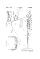
- FIG. 1 is a view in side elevation of the dipper front.
- Figure 2 is a face view of the dipper front.
- Figure 3 is a reduced view, partly in section and partly in elevation of the dipper front, the section being taken at the line 8 on Fig. 2 and viewed in the direction of the ar- I'O ⁇ V.
- Figure 4 is an enlarged sectional view taken at the lines 4 4 on Figs. 2 and 3, and viewed in the direction of the respective arrows. i
- Figure 5 is an enlarged broken sectional view taken at the line 5 on Fig. 2 and viewed in the direction of the arrow.
- FigureV 6 is an enlarged fragmentary sec- M tional view taken at the line 6 on Fig. 4 and (55 viewed in the direction of the arrow.
- Figure 7 is a sectional fragmentary view of a modification of the construction of the preceding figures, this view being taken at a A line corresponding in position with the line (6U 4-4 on Figs. 2 and 3 and viewed in the direction of the respective arrows. i
- Figure 8 is a fragmentary face view ofa dipper-front constructed in accordance with n a further modification of the invention, a portionof the structure being shown in section.
- Figure 9 is a broken section taken at the line 9 9 on Fig. 8 and viewed in the direction of the arrows. r, ,o
- Figure 10 is a view like Fig. 8 of still an-C 70 other modification; and l Figure 11, a section taken at the line 11-11 on Fig. 1()k and viewed in the direction of the arrows. c
- the dipper front therein shown isof a general shape as commonly provided, namely, of general trough shape as shown in Fig. 3 presenting side plates orfm wings 12 at which the dipper front is adapted-80 to be united withV the other slide,v walls (not shown) n ofthe dipper in accordancel with common practice.
- the dipper front'in this particular con-v struction is formed of a main body section 13 and an upper lip section 14 interlocked with the body section 13 and' presenting seats for the dipper teeth represented at 15 and cutting edge portions 16 between these teeth.f
- the body section 13 is shown as of eXternali- 90 ly ribbed construction and particularly desirable in the case of large cast dipper fronts, the transverse ribs 17 and 18 thus provided between the upper and lower edges of the body section 12 being united with longitudirV nal ribs 19.
- the rib 17'V is provided at its forward edge with an upwardly extending flange 20 shown as extending continuously across the face of l the dipper front, and the upper edge of the l 75 tend lengthwise of the dipper front, these of the rear surface of the flange 20, (Fig. 4), which latter is preferably formed with pads integral therewith to reduce theamount'of surface to be ground away to condition the parts for the desired interfitting of the parts as hereinafter described.
- a cored body portion 26 which extends along the upper edge portionfof the body sect-ion 13 and around the sides thereof as shown (Figs. 3 and 4),the'body portion 26 being formed at the-forwardredge of its base portion'27, with a skirt portion'28 lapping the forward surface of the upper edge lportieri of the body section' 13, the skirt portion 28 terminating at its lower edge in'a depending rearwardly offset flange 29 adapt- .ed'to enter the space between the.v flange A2O andthe ribs 23 asl shown'in Fig. 4 and bear .against the pads 25.
- the base 27 of the uppersection 14 is pro- 100 vided at its rear edge with a dependingflange 30 adapted to hook over the flange 21' on the body section13 and interlock therewith as shown, therear face. 31 of the flange 30 be- ⁇ ing substantially flush with the rear-surface 210522 ofthe body section 13.*;
- the upper section414 is also? provided on the rear surface of its skirt portion y23 with l.ribs 32 which'eXtend lengthwise of thezdipper front and in alinement with the ribs 23 f1-10 which they flatwise oppose as shown.
- the body portion 26 of the upper section 14 isprovided atintervals with tooth bases 33 integral therewith and in alinement, respectively, with the pairs of ribs 23 and 32.
- the rearsurface of the body portion26, between the bases 33, is inclined forwardly as ⁇ repre- 120 sented at 37 to form the series of penetrating, -or cutting, edges 16 which thus alternatewith the teeth 15, the body portion 26 between the 'bases 33 beingA cored out as represented at 125
- the teeth 15 in the particular construction shown are held at their Shanks 36 in the sockets by pins represented at 39, the teeth at opposite sides of the ShanksV 36 being formed with V-shapedrecesses 40 at which 3130 they Seaton V-shaped projections 41 formed ribs being shown as extendingY at their outer-" faces represented at 24 substantially flush with the outer face of the flange 21, but short
- the lip section 14 of theconstruction tain' constructions constituting embodiments at opposite represented at 42 are shown as overlying the ⁇ wings 12 ofthe body section 13 to which they are riveted as indicated at 43, and the sections 13aud 14 aresecured together as by means of rivets represented at 44 which pass through 80 the'alining
- Fig. 7 is the saine as the construction shown in thepreceding figures except that the portions ofthe base 26 of the upper section 14 and located between the tooth bases 33, are carried up-v ward substantial-lytothe teeth 15 instead'of terminating aconsiderable distance below the fleet; .1.1i K y i
- the modifications shown in Figs. 8,9, 10 and 11 are the sameas the construction shown "9" ⁇ in Figs. '1-6, inclusive, except that'instead 'ofprovidnig the flange 29 as ay continuous Ato which the dipper is subjected in use; is of relatively light weight; affordsthe desired smooth rear surface to the front and provides for the ready substitution of a worn lips'ection for a new one.
- a front construction of a dipper comprising a body section anda separate upper lip section, said lip section having a portion lapping a rearwardly facing surface of said body section to interlock these parts and having a portion at the front side of said body section depending to a point below the lower edge of said iirst-referred-to portion and extending continuouslyv across the front face of said bodysection. 17.
- a dipper having a front portion -forined of a body section, a separate lip 'having rearwardly extending wingss at its ends, and means connecting said wings with side portions of the dipper, said lip having a por- -tion lapping a rearwardly facingsurface of said body section and relieving stress on said -ineans in digging and a portion which depends below that portion of saidlip'section which laps a rearwardly facing4 portion of said body section and extends continuously across the front face of said body section.
- a dipper having a front portion formed of a body section, a separate lip having rearwardly extending wingss at its ends, and means connecting said wings vwith side vrportions of the dipper, said bodysection having an upwardly extending projectionbelow its upper edge, said lip having a portion lapping a rearwardly facing surface of said body section and relieving stress on said means in digging Vand aportion lapping the rear surface of said projection.
- a front construction of a dipper comprising a body section, a separate upper lip j section, said lip section lapping a rearwardly facing surface of said body section to interlock these parts and having a portion depending below the upper edge of said body section at the front side of said body section with'alineld ribs on said portion and said body section iatwise'opposing each other, and ineans extending through said alined ribs for holding said sections in lapped position.
- a front construction of a dipper corn prising a body section and a: separate upper lip section, said body section having an upwardly extending projection, and saidupper section lapping the rearwardly facing surface of said projection to interlock these parts and having a portion depending below the upper edge of said body section at the front side of said body section, with ribs between said-portion and said body section.
- a front construction of a dipper comprising a body section and a separate upper lip section, said body section being provided below its upper edge with an upwardly extending projection and said lip section lapping a rearwardly facing surface of said body section at the upper'edge of the latter and having depending lugs at its lower edge lapping the rear surface of said projection.
- a front construction of a dipper corn prising a body section and a separate upper lip section, said body section being provided below its upper edge -with a series of upwardly 'extending' projections extending transversely of said body section and said lip section lapping a rearwardly facing surface of said body section at the upper edge of the latter and having depending lugs at its lower edge alining with said projections and lapping the rear surfaces of said projections.
- a front construction of a dipper comprising a body section and a separate upper lip section, said body section being provided below its upper edge with an upwardly eX- tending projection and said lip section lapping a rearwardly facing surface of said body section and also lapping the rear surface of said projection7 that portion of said lip section which extends at the front face of said body section extending continuously across the latter and the portion of the front comprising said last referred to portion of said lip section and the portion of said body section lapped thereby being of cellular form.
- a front ⁇ construction of a clipper comprising a body section and a separate upper lip section, said lip section lapping a rearwardly facing surface of said body section to interlock these parts and having a portion depending below the upper edge of said body section at the front side of the latter and eX- tending continuously across said body section with ribs between said depending portion of said lip section and said body section.
- a front construction of a dipper corn prising a body section and a separate upper lip section, said body section being ⁇ provided below its upper edge with an upwardly extending projection and said lip section lapping a rearwardly facing surface of said body section and also lapping the rear surface of said projection with ribs between said lip and body section.
Landscapes
- Engineering & Computer Science (AREA)
- Mechanical Engineering (AREA)
- Mining & Mineral Resources (AREA)
- Civil Engineering (AREA)
- General Engineering & Computer Science (AREA)
- Structural Engineering (AREA)
- Seats For Vehicles (AREA)
Description
May 16, 1933. E s` BLACK 1,908,883
DIFFER Filed June 20, 1932 3 Sheets-Sheet l 0000000000000 OOOOOOOOOOOOOO OOOOOOOOOOOOOO HHK E. S. BLACK May 16, 1933.
DIPPER Filed June 20. 1952 3 Sheets-Sheet 2 OOOOOOOOOOO@ OOOOOGOOOOOO OOOOOOOOOOO" I w10. ,0| @n lol @101m NNW May 16, 1933. E. s. BLACK 1,908,883
DIPPER Filed June 20, 1952 5 Sheets-Sheet 3 *if f 19? SLA b9 j720 l mfg@ 28 J9 N .W
Patented May 16, 1933 UNITED STAT-Es PATENT OFFICE g EDWARD s. BLACK, or CHrCAeo, ILLINOIS, AssmNoR 'ro rn'rrrBoNnMULLixnN cf:
n COMPANY, or CHICAGO, ILLINOIS, A. conrona'rion or DELAWARE.
Application sled Junezo, 1932. serial No. 618,389.
My invention relates, more particularly, to Adippers, Vor buckets, for use 1n excavating,
dredging, or similar work, and especially to the front construction of such articles.
i i One of my objects is to provide in a front construction of dipper formed of separate parts, for the ready assembling of such parts and the presentation of a high degree of resistance to displacement of the parts relative to each other under the great stresses to which they are subjected in use.
Another object is to provide in a clipper front the cutting edge portion of which is formed as a part separate from the remainder of the front, for the connecting of these parts in a novel, simple, and highly effective way providing a construction whichvwill permit of the ready assembling, or disassembling, of these parts, as for example, for the purpose of replacement, and which will be strong and durable. v
Another object is to provide a dipper front, especially for clippers of very large capacity, which will bev of relatively light weight,
A present great strength, and which may be made of cast metal, as for example manganese steel.
Another object is to provide a two-part front construction wherein reliance on rivets or other separate fastening devices, is not required to resist the stresses in digging; and other objects as will be manifest from the following description. Referring to the accompanying drawings in whichl have chosen to illustrate my invention as embodied in a dipper front having a main body portion and a separate tooth base equipped lip forming portion: Figure 1 is a view in side elevation of the dipper front.
Figure 2 is a face view of the dipper front.
Figure 3 is a reduced view, partly in section and partly in elevation of the dipper front, the section being taken at the line 8 on Fig. 2 and viewed in the direction of the ar- I'O\V.
Figure 4 is an enlarged sectional view taken at the lines 4 4 on Figs. 2 and 3, and viewed in the direction of the respective arrows. i
Figure 5 is an enlarged broken sectional view taken at the line 5 on Fig. 2 and viewed in the direction of the arrow.
FigureV 6 is an enlarged fragmentary sec- M tional view taken at the line 6 on Fig. 4 and (55 viewed in the direction of the arrow.
Figure 7 is a sectional fragmentary view of a modification of the construction of the preceding figures, this view being taken at a A line corresponding in position with the line (6U 4-4 on Figs. 2 and 3 and viewed in the direction of the respective arrows. i
Figure 8 is a fragmentary face view ofa dipper-front constructed in accordance with n a further modification of the invention, a portionof the structure being shown in section.
Figure 9 is a broken section taken at the line 9 9 on Fig. 8 and viewed in the direction of the arrows. r, ,o
Figure 10 is a view like Fig. 8 of still an-C 70 other modification; and l Figure 11, a section taken at the line 11-11 on Fig. 1()k and viewed in the direction of the arrows. c
Referring to the construction shown in"" 1 to 6, inclusive, the dipper front therein shown isof a general shape as commonly provided, namely, of general trough shape as shown in Fig. 3 presenting side plates orfm wings 12 at which the dipper front is adapted-80 to be united withV the other slide,v walls (not shown) n ofthe dipper in accordancel with common practice. f
The dipper front'in this particular con-v struction is formed of a main body section 13 and an upper lip section 14 interlocked with the body section 13 and' presenting seats for the dipper teeth represented at 15 and cutting edge portions 16 between these teeth.f
The body section 13 is shown as of eXternali- 90 ly ribbed construction and particularly desirable in the case of large cast dipper fronts, the transverse ribs 17 and 18 thus provided between the upper and lower edges of the body section 12 being united with longitudirV nal ribs 19.
The rib 17'V is provided at its forward edge with an upwardly extending flange 20 shown as extending continuously across the face of l the dipper front, and the upper edge of the l 75 tend lengthwise of the dipper front, these of the rear surface of the flange 20, (Fig. 4), which latter is preferably formed with pads integral therewith to reduce theamount'of surface to be ground away to condition the parts for the desired interfitting of the parts as hereinafter described. l
8 shownand also provided as a casting, is
formed of a cored body portion 26 which extends along the upper edge portionfof the body sect-ion 13 and around the sides thereof as shown (Figs. 3 and 4),the'body portion 26 being formed at the-forwardredge of its base portion'27, with a skirt portion'28 lapping the forward surface of the upper edge lportieri of the body section' 13, the skirt portion 28 terminating at its lower edge in'a depending rearwardly offset flange 29 adapt- .ed'to enter the space between the.v flange A2O andthe ribs 23 asl shown'in Fig. 4 and bear .against the pads 25. Y v Y The base 27 of the uppersection 14 is pro- 100 vided at its rear edge with a dependingflange 30 adapted to hook over the flange 21' on the body section13 and interlock therewith as shown, therear face. 31 of the flange 30 be-` ing substantially flush with the rear-surface 210522 ofthe body section 13.*;
The upper section414 is also? provided on the rear surface of its skirt portion y23 with l.ribs 32 which'eXtend lengthwise of thezdipper front and in alinement with the ribs 23 f1-10 which they flatwise oppose as shown.
- The body portion 26 of the upper section 14 isprovided atintervals with tooth bases 33 integral therewith and in alinement, respectively, with the pairs of ribs 23 and 32. "The '115bases 33`are cored out as represented at 34 and prese-'nt at their outer yends sockets 35 to receive the Shanks 36 of the teeth 15. The rearsurface of the body portion26, between the bases 33, is inclined forwardly as` repre- 120 sented at 37 to form the series of penetrating, -or cutting, edges 16 which thus alternatewith the teeth 15, the body portion 26 between the 'bases 33 beingA cored out as represented at 125 The teeth 15 in the particular construction shown are held at their Shanks 36 in the sockets by pins represented at 39, the teeth at opposite sides of the ShanksV 36 being formed with V-shapedrecesses 40 at which 3130 they Seaton V-shaped projections 41 formed ribs being shown as extendingY at their outer-" faces represented at 24 substantially flush with the outer face of the flange 21, but short The lip section 14 of theconstruction tain' constructions constituting embodiments at opposite represented at 42 are shown as overlying the `wings 12 ofthe body section 13 to which they are riveted as indicated at 43, and the sections 13aud 14 aresecured together as by means of rivets represented at 44 which pass through 80 the'alining ribs 23 and 32 these ribs being preferably bulged at the portions'thereof through which the rivets pass as represented in Figs. 2 and 3 to provide the desired body of metallat `these points.
vThe modification shown in Fig. 7 is the saine as the construction shown in thepreceding figures except that the portions ofthe base 26 of the upper section 14 and located between the tooth bases 33, are carried up-v ward substantial-lytothe teeth 15 instead'of terminating aconsiderable distance below the fleet; .1.1i K y i The modifications shown in Figs. 8,9, 10 and 11 are the sameas the construction shown "9" `in Figs. '1-6, inclusive, except that'instead 'ofprovidnig the flange 29 as ay continuous Ato which the dipper is subjected in use; is of relatively light weight; affordsthe desired smooth rear surface to the front and provides for the ready substitution of a worn lips'ection for a new one. i .Y Vhilel have illustrated and described cer- 115 of myrv invention, I do not wish to be understood as intending to limit my invention the-reto, as the constructions shown maybe variously modified Vand altered and the invention embodied in other forms of structure without departing from the spirit of my inof said projections.
ping a rearwardly facing surface of saidprojection to interlock these parts and at a lower elevation lapping the front surface-of said bodyy section. l
2. A front construction of a dipper coniprising a body section and aseparate .upper section, said body section being provided be- -low its upper edge with'an upwardly extending projection and said upper section lapping a rearwardly facing surface of said body Asection at the upper edge of the latter and also lapping the rear surface of said projection, that portion of said upper section which laps the Vrear surface of said projection being wholly below the portion ofsaid upper section which laps the upper edge of said body portion.
3. A front construction of a dipper coniprising a body section and a separate upper section, said body section having an upwardly extending projection adjacent its upper -edge and oilset toward the front side of said body section and provided below its upper edge with an upwardly extending projection, said upper section lapping the rear surfaces d. A front construction of a dipper coinprising a body section and a separate upper lip section, said lip sectionlapping a rearwardly facing surface of said body section to .interlock these parts and having a portion `depending below the upper edO'e of said body 'section at the front side of said body section,
with ribs between said portion and said body section, said lip section, including said portion, extending continuously across the face of said body section. i "5. A front construction of a dipper coinprising body section, a 'separate upper lip section, said lip section lapping a rearwardly facing surface ofv said body section to inter- 'lock these parts and having a portion 'depend- .ing below the upper edge of said body sec'- tion at the front side of said 'body section, with ribs between saidportion and said body section, said-lip section, including said poi'- tion, extending continuously across the face 'of said body section and means holding said sections in lapped position.
6. A front construction of a dippercoinprising a body section and a separate upper section, said upper section lapping' a rearwardly facing surface of said body section to interlock these part-s and having a portion depending below the upper edge ofsaid body section at the front side of said body section,
.with alined ribs on said-portion and said body section flatwise opposing each other.
7. A front construction of a dippercoinprising a body section, a' separate upper section, said-upper section lapping a rearwardly .facing surface of said body section to inter'- lock these parts' and having a portion depending below the upper edge of said body sec- .tionI at the frontside of' said bodysection,
'with alined i'ibs on said portion and said body section .fiatwise opposing each other, and means extending through said alined ribs for holding said sections in lapped position. l 8. A front construction of a dipper co'in- L prising abody section anda separate upper section, saidibody section 'having an upward- -ly extending projection, and said upper sec- 'tion' having a portion lapping the rearward- Vly facing surface of said projection to inter- ".5
lock these parts andhaving a portion at lthe front side of said body section depending to a point below the lower edge of said first .referred-to portion, with ribs between said portion and said body section.
9..*A front construction of a dipper coniprising a body section and a separate upper section, said body section having an upward- Vly extending projection forwardly offset from the rear face of said body section and said upper section lapping the rearwardly facing surface of said projection to interlock these parts and having a portion depending belowthe-upper edge of said body section at the front side of said body section, with ribs between said portion and said body section.l
.j l0; A front construction of a dipper coinprising a body section and a separate upper section, said body section being provided below its upper edge with an upwardly extending projection extending continuously across saidlbody section and said upper section lapping arearwardly facing surface of said body section at the vupper edge of the latter and also lapping the rear surface of said projection'. Y n
1l. A front construction of a dipper coin- 'prising a body section and a separate upper lOS of said body section and said upper section l lapping a rearwardly facing surface of said body section at the upper edge of the latter .and having depending lugs at its lower edge alining with said projections and lapping the rear surfaces of said projections.
13. A front construction of a dipperconiprising a body section, a separate upper lip section, said lip section lapping a rearwardly facing surface of said body section and having a portion depending below the upper edge of said body section at the front side of said body section and extending continuously across tlie frontof said body section and tooth bases integral with said upper section,
prising a body section anda separate upper lip section, saidv body section having an upwardly extending projection' adjacent its upper edge and offset toward the front side of said body section and provided below its upper edge with an upwardly extending projection, said lip section lapping the rear surfaces of saidprojections. Q16.' A front construction of a dipper comprising a body section anda separate upper lip section, said lip section having a portion lapping a rearwardly facing surface of said body section to interlock these parts and having a portion at the front side of said body section depending to a point below the lower edge of said iirst-referred-to portion and extending continuouslyv across the front face of said bodysection. 17. A front construction of a"dipper coin'- prising a body section and aseparate upper section, said upper section lapping a rearwardly facing -surface of`saidfbody section to interlock these parts and having a portion depending below the upper edge of said body section at the front sideofl said body section, with projections on said body section and said depending portion of said uppersectionflat- -wise opposing each other. e. r
18. A dipper having a front portion -forined of a body section, a separate lip 'having rearwardly extendingwings at its ends, and means connecting said wings with side portions of the dipper, said lip having a por- -tion lapping a rearwardly facingsurface of said body section and relieving stress on said -ineans in digging and a portion which depends below that portion of saidlip'section which laps a rearwardly facing4 portion of said body section and extends continuously across the front face of said body section.
19. A dipper having a front portion formed of a body section, a separate lip having rearwardly extendingwings at its ends, and means connecting said wings vwith side vrportions of the dipper, said bodysection having an upwardly extending projectionbelow its upper edge, said lip having a portion lapping a rearwardly facing surface of said body section and relieving stress on said means in digging Vand aportion lapping the rear surface of said projection.
20. A front construction of a dippercomprising a body section` and a separate upper `lip section, said lip section lapping a rearysection flatwise opposing each other.
l21. A front construction of a dipper comprising a body section, a separate upper lip j section, said lip section lapping a rearwardly facing surface of said body section to interlock these parts and having a portion depending below the upper edge of said body section at the front side of said body section with'alineld ribs on said portion and said body section iatwise'opposing each other, and ineans extending through said alined ribs for holding said sections in lapped position.
22. A front construction of a dipper cornprising a body section and a: separate upper lip section, said body section having an upwardly extending projection, and saidupper section lapping the rearwardly facing surface of said projection to interlock these parts and having a portion depending below the upper edge of said body section at the front side of said body section, with ribs between said-portion and said body section.
23. A front construction of a dipper coin prising a body section and a separate uppei lip section, said body section having an upwardly extending projection forwardly offset from the rear face of said body section and said lip section lapping the rearwardly fac-V ing surface of said projection to interlock these parts and having a portion depending below the upper edge of said body section at thefront side of saidbody section, with ribs between said portion and said body section.
24. A front construction of a dipper coinprising a body section and a separate upper lip section, said body section being provided below its upper edge with an upwardly extending projection extending continuously across said body portion and said lip section lapping a rearwardly facing surface of said lbody section at the upper edge of the latter and also lapping the rear surface of said projection.
25. A front construction of a dipper comprising a body section and a separate upper lip section, said body section being provided below its upper edge with an upwardly extending projection and said lip section lapping a rearwardly facing surface of said body section at the upper'edge of the latter and having depending lugs at its lower edge lapping the rear surface of said projection.
26. A front construction of a dipper cornprising a body section and a separate upper lip section, said body section being provided below its upper edge -with a series of upwardly 'extending' projections extending transversely of said body section and said lip section lapping a rearwardly facing surface of said body section at the upper edge of the latter and having depending lugs at its lower edge alining with said projections and lapping the rear surfaces of said projections.
27. A front construction of a dipper comprising a body section and a separate upper lip section, said body section being provided below its upper edge with an upwardly eX- tending projection and said lip section lapping a rearwardly facing surface of said body section and also lapping the rear surface of said projection7 that portion of said lip section which extends at the front face of said body section extending continuously across the latter and the portion of the front comprising said last referred to portion of said lip section and the portion of said body section lapped thereby being of cellular form.
28. A front` construction of a clipper comprising a body section and a separate upper lip section, said lip section lapping a rearwardly facing surface of said body section to interlock these parts and having a portion depending below the upper edge of said body section at the front side of the latter and eX- tending continuously across said body section with ribs between said depending portion of said lip section and said body section.
29. A front construction of a dipper cornprising a body section and a separate upper lip section, said body section being` provided below its upper edge with an upwardly extending projection and said lip section lapping a rearwardly facing surface of said body section and also lapping the rear surface of said projection with ribs between said lip and body section.
EDWARD S. BLACK.
Priority Applications (1)
| Application Number | Priority Date | Filing Date | Title |
|---|---|---|---|
| US618389A US1908883A (en) | 1932-06-20 | 1932-06-20 | Dipper |
Applications Claiming Priority (1)
| Application Number | Priority Date | Filing Date | Title |
|---|---|---|---|
| US618389A US1908883A (en) | 1932-06-20 | 1932-06-20 | Dipper |
Publications (1)
| Publication Number | Publication Date |
|---|---|
| US1908883A true US1908883A (en) | 1933-05-16 |
Family
ID=24477498
Family Applications (1)
| Application Number | Title | Priority Date | Filing Date |
|---|---|---|---|
| US618389A Expired - Lifetime US1908883A (en) | 1932-06-20 | 1932-06-20 | Dipper |
Country Status (1)
| Country | Link |
|---|---|
| US (1) | US1908883A (en) |
Cited By (3)
| Publication number | Priority date | Publication date | Assignee | Title |
|---|---|---|---|---|
| US4251933A (en) * | 1979-03-05 | 1981-02-24 | Hemphill Charles W | Lip and teeth in combination with a flat bottom bucket |
| US4776114A (en) * | 1987-04-15 | 1988-10-11 | Hemphill Sr Charles W | Teeth on a tooth |
| US9963853B2 (en) | 2012-06-01 | 2018-05-08 | Esco Corporation | Lip for excavating bucket |
-
1932
- 1932-06-20 US US618389A patent/US1908883A/en not_active Expired - Lifetime
Cited By (5)
| Publication number | Priority date | Publication date | Assignee | Title |
|---|---|---|---|---|
| US4251933A (en) * | 1979-03-05 | 1981-02-24 | Hemphill Charles W | Lip and teeth in combination with a flat bottom bucket |
| US4776114A (en) * | 1987-04-15 | 1988-10-11 | Hemphill Sr Charles W | Teeth on a tooth |
| US9963853B2 (en) | 2012-06-01 | 2018-05-08 | Esco Corporation | Lip for excavating bucket |
| US10774499B2 (en) | 2012-06-01 | 2020-09-15 | Esco Group Llc | Lip for excavating bucket |
| US20200370271A1 (en) * | 2012-06-01 | 2020-11-26 | Esco Group Llc | Lip for excavating bucket |
Similar Documents
| Publication | Publication Date | Title |
|---|---|---|
| US2222071A (en) | Detachable scarifier tooth | |
| US2064059A (en) | Detachable dipper tooth | |
| US4317300A (en) | Earth working tooth with wear cap | |
| US4058173A (en) | Blade assembly with replaceable cutting edge | |
| US2259456A (en) | Bucket tooth unit | |
| US2311463A (en) | Bucket tooth | |
| US1485879A (en) | Detachable tooth for excavating shovels | |
| US3307277A (en) | Bucket attachment | |
| US4006544A (en) | Replaceable cutting edge assembly | |
| US1908883A (en) | Dipper | |
| US2005016A (en) | Digging tooth | |
| US2987838A (en) | Excavating tooth | |
| US2164988A (en) | Clamshell bucket | |
| US2674816A (en) | Excavting tooth with replaceable point | |
| US3088232A (en) | Replaceable shoe for scraper bowl edges | |
| US1363189A (en) | Tooth for shovel-dippers | |
| US2114129A (en) | Dredge bucket | |
| US1815649A (en) | Replaceable excavator tooth | |
| US1580725A (en) | Ditch-excavating bucket | |
| US1430782A (en) | Lip for dredge buckets | |
| US2576225A (en) | Detachable locking means for an excavating bucket tooth | |
| CA2036118C (en) | Replaceable wear element and method | |
| US1914104A (en) | Dipper construction | |
| US1770543A (en) | Excavating dipper | |
| US2386424A (en) | Plowshare |