JP6333345B2 - Electromagnetic induction encoder - Google Patents
Electromagnetic induction encoder Download PDFInfo
- Publication number
- JP6333345B2 JP6333345B2 JP2016237422A JP2016237422A JP6333345B2 JP 6333345 B2 JP6333345 B2 JP 6333345B2 JP 2016237422 A JP2016237422 A JP 2016237422A JP 2016237422 A JP2016237422 A JP 2016237422A JP 6333345 B2 JP6333345 B2 JP 6333345B2
- Authority
- JP
- Japan
- Prior art keywords
- scale
- measurement
- electromagnetic induction
- scanning
- induction encoder
- Prior art date
- Legal status (The legal status is an assumption and is not a legal conclusion. Google has not performed a legal analysis and makes no representation as to the accuracy of the status listed.)
- Active
Links
Images


Classifications
-
- G—PHYSICS
- G01—MEASURING; TESTING
- G01D—MEASURING NOT SPECIALLY ADAPTED FOR A SPECIFIC VARIABLE; ARRANGEMENTS FOR MEASURING TWO OR MORE VARIABLES NOT COVERED IN A SINGLE OTHER SUBCLASS; TARIFF METERING APPARATUS; MEASURING OR TESTING NOT OTHERWISE PROVIDED FOR
- G01D5/00—Mechanical means for transferring the output of a sensing member; Means for converting the output of a sensing member to another variable where the form or nature of the sensing member does not constrain the means for converting; Transducers not specially adapted for a specific variable
- G01D5/12—Mechanical means for transferring the output of a sensing member; Means for converting the output of a sensing member to another variable where the form or nature of the sensing member does not constrain the means for converting; Transducers not specially adapted for a specific variable using electric or magnetic means
- G01D5/14—Mechanical means for transferring the output of a sensing member; Means for converting the output of a sensing member to another variable where the form or nature of the sensing member does not constrain the means for converting; Transducers not specially adapted for a specific variable using electric or magnetic means influencing the magnitude of a current or voltage
- G01D5/20—Mechanical means for transferring the output of a sensing member; Means for converting the output of a sensing member to another variable where the form or nature of the sensing member does not constrain the means for converting; Transducers not specially adapted for a specific variable using electric or magnetic means influencing the magnitude of a current or voltage by varying inductance, e.g. by a movable armature
- G01D5/2006—Mechanical means for transferring the output of a sensing member; Means for converting the output of a sensing member to another variable where the form or nature of the sensing member does not constrain the means for converting; Transducers not specially adapted for a specific variable using electric or magnetic means influencing the magnitude of a current or voltage by varying inductance, e.g. by a movable armature by influencing the self-induction of one or more coils
- G01D5/2013—Mechanical means for transferring the output of a sensing member; Means for converting the output of a sensing member to another variable where the form or nature of the sensing member does not constrain the means for converting; Transducers not specially adapted for a specific variable using electric or magnetic means influencing the magnitude of a current or voltage by varying inductance, e.g. by a movable armature by influencing the self-induction of one or more coils by a movable ferromagnetic element, e.g. a core
-
- G—PHYSICS
- G01—MEASURING; TESTING
- G01B—MEASURING LENGTH, THICKNESS OR SIMILAR LINEAR DIMENSIONS; MEASURING ANGLES; MEASURING AREAS; MEASURING IRREGULARITIES OF SURFACES OR CONTOURS
- G01B7/00—Measuring arrangements characterised by the use of electric or magnetic techniques
- G01B7/003—Measuring arrangements characterised by the use of electric or magnetic techniques for measuring position, not involving coordinate determination
-
- G—PHYSICS
- G01—MEASURING; TESTING
- G01D—MEASURING NOT SPECIALLY ADAPTED FOR A SPECIFIC VARIABLE; ARRANGEMENTS FOR MEASURING TWO OR MORE VARIABLES NOT COVERED IN A SINGLE OTHER SUBCLASS; TARIFF METERING APPARATUS; MEASURING OR TESTING NOT OTHERWISE PROVIDED FOR
- G01D5/00—Mechanical means for transferring the output of a sensing member; Means for converting the output of a sensing member to another variable where the form or nature of the sensing member does not constrain the means for converting; Transducers not specially adapted for a specific variable
- G01D5/12—Mechanical means for transferring the output of a sensing member; Means for converting the output of a sensing member to another variable where the form or nature of the sensing member does not constrain the means for converting; Transducers not specially adapted for a specific variable using electric or magnetic means
- G01D5/14—Mechanical means for transferring the output of a sensing member; Means for converting the output of a sensing member to another variable where the form or nature of the sensing member does not constrain the means for converting; Transducers not specially adapted for a specific variable using electric or magnetic means influencing the magnitude of a current or voltage
- G01D5/20—Mechanical means for transferring the output of a sensing member; Means for converting the output of a sensing member to another variable where the form or nature of the sensing member does not constrain the means for converting; Transducers not specially adapted for a specific variable using electric or magnetic means influencing the magnitude of a current or voltage by varying inductance, e.g. by a movable armature
- G01D5/204—Mechanical means for transferring the output of a sensing member; Means for converting the output of a sensing member to another variable where the form or nature of the sensing member does not constrain the means for converting; Transducers not specially adapted for a specific variable using electric or magnetic means influencing the magnitude of a current or voltage by varying inductance, e.g. by a movable armature by influencing the mutual induction between two or more coils
- G01D5/2053—Mechanical means for transferring the output of a sensing member; Means for converting the output of a sensing member to another variable where the form or nature of the sensing member does not constrain the means for converting; Transducers not specially adapted for a specific variable using electric or magnetic means influencing the magnitude of a current or voltage by varying inductance, e.g. by a movable armature by influencing the mutual induction between two or more coils by a movable non-ferromagnetic conductive element
-
- G—PHYSICS
- G01—MEASURING; TESTING
- G01B—MEASURING LENGTH, THICKNESS OR SIMILAR LINEAR DIMENSIONS; MEASURING ANGLES; MEASURING AREAS; MEASURING IRREGULARITIES OF SURFACES OR CONTOURS
- G01B7/00—Measuring arrangements characterised by the use of electric or magnetic techniques
- G01B7/02—Measuring arrangements characterised by the use of electric or magnetic techniques for measuring length, width or thickness
-
- G—PHYSICS
- G01—MEASURING; TESTING
- G01B—MEASURING LENGTH, THICKNESS OR SIMILAR LINEAR DIMENSIONS; MEASURING ANGLES; MEASURING AREAS; MEASURING IRREGULARITIES OF SURFACES OR CONTOURS
- G01B7/00—Measuring arrangements characterised by the use of electric or magnetic techniques
- G01B7/30—Measuring arrangements characterised by the use of electric or magnetic techniques for measuring angles or tapers; for testing the alignment of axes
-
- G—PHYSICS
- G01—MEASURING; TESTING
- G01D—MEASURING NOT SPECIALLY ADAPTED FOR A SPECIFIC VARIABLE; ARRANGEMENTS FOR MEASURING TWO OR MORE VARIABLES NOT COVERED IN A SINGLE OTHER SUBCLASS; TARIFF METERING APPARATUS; MEASURING OR TESTING NOT OTHERWISE PROVIDED FOR
- G01D5/00—Mechanical means for transferring the output of a sensing member; Means for converting the output of a sensing member to another variable where the form or nature of the sensing member does not constrain the means for converting; Transducers not specially adapted for a specific variable
- G01D5/12—Mechanical means for transferring the output of a sensing member; Means for converting the output of a sensing member to another variable where the form or nature of the sensing member does not constrain the means for converting; Transducers not specially adapted for a specific variable using electric or magnetic means
- G01D5/244—Mechanical means for transferring the output of a sensing member; Means for converting the output of a sensing member to another variable where the form or nature of the sensing member does not constrain the means for converting; Transducers not specially adapted for a specific variable using electric or magnetic means influencing characteristics of pulses or pulse trains; generating pulses or pulse trains
- G01D5/245—Mechanical means for transferring the output of a sensing member; Means for converting the output of a sensing member to another variable where the form or nature of the sensing member does not constrain the means for converting; Transducers not specially adapted for a specific variable using electric or magnetic means influencing characteristics of pulses or pulse trains; generating pulses or pulse trains using a variable number of pulses in a train
- G01D5/2451—Incremental encoders
- G01D5/2452—Incremental encoders incorporating two or more tracks having an (n, n+1, ...) relationship
Description
電磁誘導式エンコーダは、互いに移動可能な2つの構造部品の位置を測定するために使用される。この電磁誘導式エンコーダは、例えば、互いに相対回転可能な2つの機械部品の角度位置を測定するためのロータリーエンコーダとして又は軸に沿った長手方向の移動を直接に測定するための測長システムとして使用される。 An electromagnetic induction encoder is used to measure the position of two structural parts that are movable relative to each other. This electromagnetic induction encoder can be used, for example, as a rotary encoder to measure the angular position of two mechanical parts that can rotate relative to each other or as a length measuring system to directly measure longitudinal movement along an axis. Is done.
このような電磁誘導式エンコーダは、電気駆動用の測定機器として対応する複数の機械部品の相対移動又は相対位置を測定するために使用される。この場合には、生成された位置値が、対応するインタフェース装置を介して当該駆動を制御するための後続電子装置に供給される。エンコーダは、インクリメンタル式エンコーダとアブソリュート式エンコーダとに区別される。アブソリュート式エンコーダが、益々要求されつつある。 Such an electromagnetic induction encoder is used to measure relative movement or relative position of a plurality of mechanical parts corresponding as a measurement device for electric drive. In this case, the generated position value is supplied to the subsequent electronic device for controlling the drive via the corresponding interface device. Encoders are classified into incremental encoders and absolute encoders. There is an increasing demand for absolute encoders.
このような種類のアブソリュート式の電磁誘導式エンコーダは、欧州特許第1081454号明細書から公知である。絶対位置が、僅かに異なる周期の測定目盛を有する2つの測定目盛を電磁誘導式に走査することによって得られる(バーニヤスケール原理)。これらの測定目盛はそれぞれ、1つの励磁巻線と1つの走査巻線との間の電磁誘導結合の強さに位置に応じて影響を及ぼす。当該2つの測定目盛を走査するための複数のコイル装置が、これらの測定目盛間の中間空間内又は隙間内に配置されている。 An absolute electromagnetic induction encoder of this kind is known from EP 1084454. The absolute position is obtained by scanning two measurement graduations with slightly different periods of measurement graduations in an electromagnetic induction manner (vernier scale principle). Each of these measurement scales affects the strength of the electromagnetic inductive coupling between one excitation winding and one scanning winding depending on the position. A plurality of coil devices for scanning the two measurement graduations are arranged in an intermediate space or a gap between these measurement graduations.
本発明の課題は、正確な絶対位置が検出され得、コンパクトで且つ丈夫な構造を有する電磁誘導式エンコーダを提供することにある。 An object of the present invention is to provide an electromagnetic induction encoder that can detect an accurate absolute position and has a compact and durable structure.
本発明によれば、この課題は、請求項1に記載の特徴によって解決される。
According to the invention, this problem is solved by the features of
したがって、前記電磁誘導式エンコーダは、1つのスケール装置と1つの走査装置とを有する。
・前記スケール装置は、測定方向に延在する1つの第1測定目盛と、この第1測定目盛に対して平行に延在し、この第1測定目盛に対向する1つの第2測定目盛とを有する。
・前記走査装置は、前記第1測定目盛と前記第2測定目盛との間の隙間内に配置されていて、位置を測定するために前記スケール装置に対して測定方向に移動可能である。この場合、前記走査装置は、前記第1測定目盛を走査し、第1の位置に依存する第1走査信号を生成するために1つの第1コイル装置を有し、前記走査装置は、前記第2測定目盛を走査し、第2の位置に依存する第2走査信号を生成するために前記第1コイル装置に対向する1つの第2コイル装置を有する。
Therefore, the electromagnetic induction type encoder has one scale device and one scanning device.
The scale device includes one first measurement scale extending in the measurement direction and one second measurement scale extending in parallel to the first measurement scale and facing the first measurement scale. Have.
The scanning device is disposed in a gap between the first measurement scale and the second measurement scale, and is movable in the measurement direction with respect to the scale device in order to measure the position. In this case, the scanning device has one first coil device for scanning the first measurement graduation and generating a first scanning signal dependent on a first position, and the scanning device includes the first measurement scale. There is one second coil device facing the first coil device for scanning the two measurement scales and generating a second scanning signal dependent on the second position.
この場合、軟磁性材料から成る少なくとも1つの中間層が、前記第1コイル装置と前記第2コイル装置との間に配置されている。 In this case, at least one intermediate layer made of a soft magnetic material is disposed between the first coil device and the second coil device.
軟磁性材料は、磁場内で容易に磁化され得る強磁性材料である。当該材料中の磁気分極が、外部磁場をその材料の透磁率だけ増幅する。当該軟磁性材料は、塊状の金属として、結合された金属粉末として、セラミック材料、いわゆるフェライトとして、又は合成樹脂で結合されたフェライト粉末として存在する。 Soft magnetic materials are ferromagnetic materials that can be easily magnetized in a magnetic field. Magnetic polarization in the material amplifies the external magnetic field by the magnetic permeability of the material. The soft magnetic material exists as a bulk metal, as a bound metal powder, as a ceramic material, so-called ferrite, or as a ferrite powder bound with a synthetic resin.
中間層としての前記軟磁性材料は、前記第1コイル装置から発生する交番磁場の磁力線を前記中間層の材料の層中に通させる結果、閉じて空間的に限定された磁気ループを形成し、且つ前記第2コイル装置から発生する交番磁場の磁力線を前記中間層の材料の層中に通させる結果、閉じて空間的に限定された磁気ループを形成する機能を有する。これにより、前記中間層は、前記第1コイル装置から発生する磁力線を前記第2コイル装置から発生する磁力線から分離する。 The soft magnetic material as the intermediate layer closes and forms a spatially limited magnetic loop as a result of passing the magnetic field lines of the alternating magnetic field generated from the first coil device through the layer of the intermediate layer material, In addition, as a result of passing the magnetic field lines of the alternating magnetic field generated from the second coil device through the material layer of the intermediate layer, it has a function of closing and forming a spatially limited magnetic loop. Thereby, the intermediate layer separates the magnetic field lines generated from the first coil device from the magnetic field lines generated from the second coil device.
1つのコアと、このコアの両面上に配置された軟磁性材料から成る1つの層とから構成されるサンドイッチ構造が、中間層として特に適する。当該軟磁性材料は、2MHz程度の範囲内の交番磁場の場合に、例えば1×10⁶Ωの大きさの大きい電気抵抗を有する、すなわち実質的に非導電性である。このような材料は、FFD材料(Flux Field Directional Material;フラックス・フィールド・ディレクショナル・マテリアル)であり、「焼結フェライトシート」としてフィルムの形で商業的に入手可能である。悪い導電率に起因して、それぞれのコイル装置の励磁磁場を減衰させる渦電流が、この材料中で発生しない。 A sandwich structure composed of one core and one layer made of a soft magnetic material disposed on both sides of the core is particularly suitable as an intermediate layer. In the case of an alternating magnetic field in the range of about 2 MHz, the soft magnetic material has a large electric resistance of, for example, 1 × 10 6 Ω, that is, is substantially nonconductive. Such a material is an FFD material (Flux Field Directional Material) and is commercially available in the form of a film as a “sintered ferrite sheet”. Due to the poor conductivity, eddy currents that attenuate the excitation magnetic field of the respective coil device do not occur in this material.
当該コアが、同様に、特に軟磁性材料から成る。特に、当該コアの材料の透磁率は、その両面に配置された層の透磁率よりも十分に−特に数倍だけ−大きい。この場合には、当該コアが、外部磁場から発生する干渉磁束を吸収し、当該層を飽和させない。すなわち、エンコーダが、外部磁場に曝されている場合、この外部磁場が、当該機能層を飽和させることが回避される必要がある。何故なら、飽和が回避されない場合は、磁束を増幅させる作用がもはや与えられないからである。特に軟磁性鋼が、当該コア用の材料として適する。 The core is likewise composed in particular of a soft magnetic material. In particular, the permeability of the material of the core is sufficiently greater, in particular several times greater, than the permeability of the layers arranged on both sides. In this case, the core absorbs the interference magnetic flux generated from the external magnetic field and does not saturate the layer. That is, when the encoder is exposed to an external magnetic field, it is necessary to avoid the external magnetic field from saturating the functional layer. This is because if saturation is not avoided, the effect of amplifying the magnetic flux is no longer provided. In particular, soft magnetic steel is suitable as a material for the core.
当該金属製の中間層は、μメタル、すなわち10,000を超える非常に高い透磁率を有する金属でもよい。この軟磁性材料は、良好な導電性である。2MHzの大きさの交番磁場の場合の当該極めて高い透磁率に起因して、当該交番磁場の侵入深さは、非常に浅く、当該侵入深さは、数μmの深さに及ぶだけである。その結果、その実効電気抵抗は、非常に大きいので、同様に、当該それぞれのコイル装置の励磁磁場に逆らって作用し、当該励磁磁場を減衰させ得る渦電流が発生しないか又は無視できる程度にしか発生しない。 The metal intermediate layer may be μ metal, ie a metal having a very high magnetic permeability exceeding 10,000. This soft magnetic material has good conductivity. Due to the extremely high permeability in the case of an alternating magnetic field with a magnitude of 2 MHz, the penetration depth of the alternating magnetic field is very shallow and the penetration depth only reaches a depth of a few μm. As a result, its effective electrical resistance is so large that it acts similarly to the excitation magnetic field of the respective coil device, and eddy currents that can attenuate the excitation magnetic field are not generated or negligible. Does not occur.
本発明の好適な構成は、従属請求項に記載されている。 Preferred configurations of the invention are described in the dependent claims.
本発明の電磁誘導式エンコーダの詳細及び利点は、添付図面に基づく以下の実施の形態に記載されている。 Details and advantages of the electromagnetic induction encoder of the present invention will be described in the following embodiments based on the accompanying drawings.
本発明の第1の実施の形態を図1〜4に基づいて詳しく説明する。図1は、測定方向Xに延在する2つの測定目盛11及び12を有するスケール装置1を示す。これらの測定目盛11及び12は、互いに対向して配置されていて、これらの測定目盛11及び12間に隙間を形成する。第1測定目盛11は、第1目盛周期P1を有する目盛要素を備え、第2測定目盛12は、第2目盛周期P2を有する目盛要素を備える。両測定目盛11,12の周期的に配置されたこれらの測定目盛11,12は、電磁誘導式に走査可能に形成されている。このため、これらの測定目盛11,12はそれぞれ、測定方向Xに互いに離間して周期的に連続する導電性の複数の目盛要素から構成される。当該図示された実施の形態では、これらの目盛要素は、扁平な複数の長方形である。しかし、これらの目盛要素は、別の形、例えば湾曲された外輪郭又は三角形状の外輪郭を成してもよい。これらの目盛要素は、複数の電磁誘導結合要素を形成する。励磁磁場に逆らって作用する渦電流が、1つの目盛要素ごとに発生することによって、これらの電磁誘導結合要素は、励磁巻線210,220と走査巻線211,212,221,222との間の電磁誘導結合の強さを位置に応じて変調する。図4には、測定目盛11のこれらの目盛要素中に発生する渦電流が概略的に示されている。
A first embodiment of the present invention will be described in detail with reference to FIGS. FIG. 1 shows a
第1測定目盛11の目盛周期P1と、第2測定目盛12の目盛周期P2とは、僅かだけ相違する。その結果、絶対位置が、これらの目盛周期P1,P2のうちの複数の目盛周期によって当該僅かな相違から導き出され得る。したがって、当該絶対位置測定は、バーニヤスケール原理に基づく。
The scale period P1 of the
さらに、当該電磁誘導式エンコーダは、スケール装置1の2つの測定目盛11及び12を走査するために、第1測定目盛11と第2測定目盛12との間に配置されている走査装置2を有する。この走査装置2は、位置測定のために、スケール装置1に対して測定方向Xに相対移動可能である。この走査装置2は、第1測定目盛11を走査し、第1の位置に依存する少なくとも1つの第1走査信号S1を生成するために、第1コイル装置21を有する。この走査装置2は、第2測定目盛12を走査し、第2の位置に依存する少なくとも1つの第2走査信号S2を生成するために、第2コイル装置22を有する。
Furthermore, the electromagnetic induction encoder has a
第1コイル装置21は、1つの第1励磁巻線210と、互いに移相されている周期的な複数の第1走査巻線211,212を有する。同様に、第2コイル装置22は、第2測定目盛12を走査するために、1つの第2励磁巻線220と、互いに移相されている周期的な複数の第2走査巻線221,222を有する。第1走査巻線211,212はそれぞれ、第1測定目盛11の、測定方向Xに配置された複数の目盛要素を同時に走査し、互いに移相されている、信号周期P1を有する複数の第1走査信号S1,S11を生成するために、測定方向Xに延在する周期的な複数の巻線を有する。第2走査巻線221,222はそれぞれ、第2測定目盛12の、測定方向Xに配置された複数の目盛要素を同時に走査し、互いに移相されている、信号周期P2を有する複数の第2走査信号S2,S21を生成するために、測定方向Xに延在する周期的な複数の巻線を有する。
The
スケール装置1との協働時の電磁誘導走査の機能を詳しく説明するため、走査装置2が、図3に概略的に示されている。
In order to explain in detail the function of electromagnetic induction scanning in cooperation with the
時間的に交番する電磁的な励磁磁場が、第1測定目盛11の複数の目盛要素の領域内に生成されるように、扁平な励磁巻線210が、励磁電流によって通電される。この励磁電流は、100kHz〜10MHzの周波数を有する。励磁巻線210が、第1測定目盛11の、対向して連続する複数の目盛要素内に、可能な限り均一な電磁場を形成するように、この励磁巻線210は空間配置されている。
The flat excitation winding 210 is energized by the excitation current so that electromagnetic excitation magnetic fields alternating in time are generated in the areas of the plurality of scale elements of the
走査巻線211,212は、励磁巻線210の内部に存在する。この励磁巻線210から発生した励磁磁場が、当該複数の目盛要素中に当該励磁磁場に逆らう対抗磁場として作用する渦電流を生成する。当該導電性の複数の目盛要素に対する相対位置によって決まる電圧が、これらの走査巻線211,212に割り当てられた当該励磁磁場に起因してこれらの走査巻線211,212内に誘導される。すなわち、励磁巻線210が、当該複数の目盛要素に対する相対位置に応じて測定方向Xに走査巻線211,212と電磁誘導結合されている。当該電磁的な交番磁場が、これらの目盛要素によって測定方向Xに位置に応じて変調される。これにより、走査巻線211,212中に誘導された電圧も、位置に応じて変化する。これらの走査巻線211,212中にそれぞれ誘導された電圧が、走査信号S1,S11として評価装置3に供給される。
The
時間的に交番する電磁的な励磁磁場が、第2測定目盛12の複数の目盛要素の領域内に生成されるように、扁平な励磁巻線220が、励磁電流によって通電される。この励磁電流は、数MHzの周波数を有する。励磁巻線220が、対向して連続する複数の目盛要素内に、可能な限り均一な電磁場を形成するように、この励磁巻線220は空間配置されている。
The flat excitation winding 220 is energized by the excitation current so that electromagnetic excitation magnetic fields alternating in time are generated in the areas of the plurality of scale elements of the
走査巻線221,222は、励磁巻線220の内部に存在する。この励磁巻線220から発生した励磁磁場が、当該複数の目盛要素中に当該励磁磁場に逆らう対抗磁場として作用する渦電流を生成する。当該導電性の複数の目盛要素に対する相対位置によって決まる電圧が、これらの走査巻線221,222に割り当てられた当該励磁磁場に起因してこれらの走査巻線221,222内に誘導される。すなわち、励磁巻線220が、当該複数の目盛要素に対する相対位置に応じて測定方向Xに電磁誘導結合されている。当該電磁的な交番磁場が、これらの目盛要素によって測定方向Xに位置に応じて変調される。これにより、走査巻線221,222中に誘導された電圧も、位置に応じて変化する。これらの走査巻線221,222中にそれぞれ誘導された電圧が、走査信号S2,S21として評価装置3に供給される。
The
走査信号S1,S11,S2,S21が、走査装置2の評価装置3に入力される。スケール装置1に対する走査装置2の一義的な絶対位置APを示すビート信号を、複数の位相位置の比較から既知の方法で生成するように、この評価装置3は構成されている。コード化すべき絶対測定範囲が、2つの目盛周期P1,P2の選択された差によって既知の方法で決まる。目盛周期P1の数と、目盛周期P2の数とが、コード化すべき絶対測定範囲の全体にわたって1だけ異なると、特に有益である。絶対位置APが、デジタルデータ語として走査装置2の出力部に供給される。この場合、当該出力は、シリアルに実行される。走査装置2の構成を断面図である図2に基づいて詳しく説明する。励磁巻線210と走査巻線211,212とを有する第1コイル装置21が、第1測定目盛11に対して僅かな走査間隔をあけて第1回路基板側4に配置されている。励磁巻線220と走査巻線221,222とを有する第2コイル装置22が、第2測定目盛12に対して僅かな走査間隔をあけて第2回路基板側5に配置されている。軟磁性材料から成る中間層6が、第1コイル装置21と第2コイル装置22との間に配置されている。
Scanning signals
中間層6としての当該軟磁性材料は、第1コイル装置21から発生する交番磁場の磁力線を中間層6の材料の層中に通させる結果、閉じて空間的に限定された磁気ループを形成し、且つ第2コイル装置22から発生する交番磁場の磁力線を中間層6の材料の層中に通させる結果、閉じて空間的に限定された磁気ループを形成する機能を有する。これにより、中間層6は、第1コイル装置21から発生する磁力線を第2コイル装置22から発生する磁力線から分離する。
The soft magnetic material as the intermediate layer 6 closes and forms a spatially limited magnetic loop as a result of passing the magnetic field lines of the alternating magnetic field generated from the
当該第1の実施の形態では、当該中間層が、軟磁性コア7から成る。この軟磁性コア7は、両面に非導電性の軟磁性材料から成るそれぞれ1つの層8,9を有する。交番磁場の数MHz(例えば、2MHz)の周波数の場合の悪い導電率に起因して、それぞれのコイル装置21,22の励磁磁場を減衰させる渦電流が、層8,9中に発生しない。これらの層8,9の比較的高い(1よりも非常に高い)透磁率に起因して、当該励磁磁場が、これらの層8,9中に誘導される、したがって増幅される。
In the first embodiment, the intermediate layer is composed of the soft
これにより、非常に多くの磁束が、コア7まで達することが回避される。その結果、当該励磁磁場を減衰させ得る渦電流が、コア7で発生し得ない。層8,9の厚さはそれぞれ、特に100μm〜1000μmである。好ましくは、コア7は、導電性の軟磁性金属から成る。特に軟磁性鋼が、当該コア用の材料として適する。コア7の厚さは、数mmである。
Thereby, a very large amount of magnetic flux is prevented from reaching the
コア7の透磁率は、特に2つの層8,9の透磁率よりも大きい。したがって、コア7中の磁束密度が、層8,9中よりも大きいことが達成される。それ故に、外部磁場(干渉磁場)の大部分が、コア7を透過し、層8,9が、容易に飽和し得ない。コア7の透磁率は、特に層8,9の透磁率よりも約数倍大きい。当該コアの透磁率が、300の大きさの場合、これらの層の透磁率は、100kHz〜10MHzの周波数のときに100未満の範囲内になければならない。
The magnetic permeability of the
特に、軟磁性粒子が封入されている非導電性のマトリックス材料が、それぞれの層8,9のために適する。それ故に、当該層8,9は、Flux Field Directional Materialから成るフィルムから形成され得る。軟磁性粒子が粉末状に混入されている合成樹脂、特にエポキシ樹脂が、マトリックス材料として適する。
In particular, a non-conductive matrix material in which soft magnetic particles are encapsulated is suitable for the
中央に配置されたコア7と、その両面上に配置された層8,9と、当該層上に装着された回路基板4,5と、当該回路基板上に装着された扁平なコイル装置21,22とが、サンドイッチ状のスタックを形成する。コンパクトな構造が達成され、機械的に安定な構造も、金属製のコア7によって達成される。
A
層8,9と回路基板4,5とが、繊維とマトリックス材料と軟磁性粒子とを含むプレプレグとして一緒に製造されてもよい。コア7と、層8,9と、回路基板4,5とは、多層構造を形成し得る。この場合、個々の層が、熱作用の下で互いにプレスされている。硬くてコンパクトなサンドイッチ構造が得られる。
図5には、走査装置2.1の別の構造が示されている。軟磁性の中間層6.1が、この場合にはμメタルから成る。この実施の形態では、層8,9は必ずしも必要でない。その結果、コイル装置21,22を有する回路基板4,5が、当該μメタル上に直接に装着され得る。μメタルとしての中間層6.1は、導電性である。しかし、2MHzの大きさの交番磁場の場合の極めて高い透磁率に起因して、当該交番磁場の侵入深さは、非常に浅く、数μmの深さに及ぶだけである。その結果、その実効電気抵抗は、非常に大きいので、同様に、当該それぞれのコイル装置の励磁磁場に逆らって作用し、当該励磁磁場を減衰させ得る渦電流が発生しないか又はほとんど発生しない。
FIG. 5 shows another structure of the scanning device 2.1. The soft magnetic intermediate layer 6.1 is in this case made of μ metal. In this embodiment, the
上記の実施の形態では、スケール装置1は、U字形の形材から形成されている。測定目盛11,12が、このスケール装置1の互いに平行に延在する2つの脚部内に又は当該脚部に形成されている。第1測定目盛11が、当該2つの脚部のうちの1つの脚部内に形成されていて、第2測定目盛12が、この第1測定目盛11に対して対向し且つ平行に延在する当該U字形の形材の別の脚部内に形成されている。スケール装置1は、走査装置2又は2.1を言わば包囲する。
In said embodiment, the
当該実施の形態では、複数の目盛要素が、複数の電磁誘導結合要素を形成する。励磁磁場に逆らって作用する渦電流が、1つの目盛要素ごとに発生することによって、これらの電磁誘導結合要素は、励磁巻線210,220と走査巻線211,212,221,222との間の電磁誘導結合の強さを位置に応じて変調する。この場合には、特に良好な導電性で且つ非磁性の材料、例えばアルミニウムが、スケール装置1用の材料として適する。
In the embodiment, the plurality of scale elements form a plurality of electromagnetic induction coupling elements. An eddy current acting against the excitation magnetic field is generated for each scale element, so that these electromagnetic inductive coupling elements are located between the
図1は、U字断面状(U字状の形材)のスケール装置1の特に好適な構造を示す。この場合、第1測定目盛11及び第2測定目盛12はそれぞれ、連続する複数の歯と複数の歯間とから構成される。これらの歯間が、当該U字状断面の底部まで達しないならば、すなわち、これらの歯間の両側が、当該U字状断面の底部に接しても依然として測定方向Xに連続して延在する複数のウェブを残すならば、当該スケール装置1は、非常に曲がりにくい。
FIG. 1 shows a particularly preferred structure of a
U字状断面としてのスケール装置1の実施の形態には、スケール装置1が一体的に形成されていて、測定目盛11,12が、必要な精度で互いに整向して形成され得るという利点がある。第1測定目盛11及び第2測定目盛12は、レーザー又はウォータージェットを用いた打ち抜き、切断によって形成され得る。当該第1測定目盛11及び第2測定目盛12は、その後にU字状断面に曲げられる。当該U字状断面は、特にリニアスケール装置として使用するために高い曲げ剛性を有し、自己支持形であり、それ故にスケール装置1として良好に取り扱い可能である。
The embodiment of the
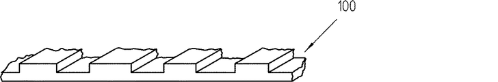
代わりに、スケール装置100の目盛要素は、図6にしたがって形成されてもよい。この場合、歯間がそれぞれ、材料減少部分によって置換されていて、目盛要素が、走査装置2を先導する隆起部分として形成されている。この別の構造も、U字状断面の互いに対向する2つの脚部内に設けられ得る。この場合、非常に曲がりにくい構造が得られる。
Alternatively, the scale element of the
上記の実施の形態及びバーニヤスケール原理の利用では、第1測定目盛11の目盛周期P1が、付随する走査巻線211,212の目盛周期P1と一致し、第2測定目盛12の目盛周期P2が、付随する走査巻線221,222の目盛周期P2と一致する。この場合、P1とP2とは、僅かに相違する。この代わりに、バーニヤスケール原理を利用する場合は、第1測定目盛11を走査するための走査巻線の目盛周期と、第2測定目盛12を走査するための目盛周期とは、欧州特許出願公開第2851655号明細書で説明されているように同一でもよい。
In the use of the above embodiment and the vernier scale principle, the scale period P1 of the
上記の実施の形態では、複数の目盛要素が、複数の電磁誘導結合要素を形成する。励磁磁場に逆らって−すなわち、磁束を減衰させるように−作用する渦電流が、1つの目盛要素ごとに発生することによって、これらの電磁誘導結合要素は、励磁巻線210,220と走査巻線211,212,221,222との間の電磁誘導結合の強さを位置に応じて変調する。しかし、当該複数の目盛要素が、磁束を増幅するように、当該スケール装置が構成されてもよい。この場合には、当該スケール装置は、例えば粉末状の軟磁性材料又はフェライトで充填されている合成樹脂から成り得る。このとき、当該スケール装置は、射出成形部材として形成され得る。
In the above embodiment, the plurality of scale elements form a plurality of electromagnetic inductive coupling elements. An eddy current acting against the excitation magnetic field, i.e., to attenuate the magnetic flux, is generated for each graduation element, so that these electromagnetic inductive coupling elements are coupled with the
図示されていない構成では、スケール装置の第1測定目盛が、チェーンコードでもよい。当該チェーンコードは、知られているようにビット列から構成される。これらのビットのうちの複数のビットが、測定方向に連続して同時に走査され、絶対位置を一義的に決定する1つのコード語を粗い絶対位置として形成する。この場合には、第2測定目盛が、周期的なインクリメンタル目盛でもよい。当該インクリメンタル目盛は、補間によってチェーンコードから測定される絶対位置をさらに分割し、1つの精密な位置を形成する。評価装置が、当該チェーンコードの粗い絶対位置と当該インクリメンタル目盛の精密な位置とをその結果として生成される1つの絶対位置に結合する。 In a configuration not shown, the first measurement scale of the scale device may be a chain cord. The chain code is composed of a bit string as is known. A plurality of these bits are scanned simultaneously in succession in the measurement direction to form one code word as a coarse absolute position that uniquely determines the absolute position. In this case, the second measurement scale may be a periodic incremental scale. The incremental scale further divides the absolute position measured from the chain code by interpolation to form one precise position. An evaluation device combines the coarse absolute position of the chain code and the precise position of the incremental scale into one resulting absolute position.
代わりに、1つの測定目盛が、周期的なそれぞれ1つのインクリメンタル目盛を有する複数のトラックから構成されてもよい。 Alternatively, one measurement scale may be composed of a plurality of tracks each having a periodic incremental scale.
図示されていない構成では、複数の走査装置が、位置を測定するためにスケール装置に付設されてもよい。前後して配置された継ぎ目のある複数のスケール装置を走査する場合、当該構成は、冗長な位置測定のために使用され得るか、又はその継ぎ目を横切るときの中断しない位置測定を保証するために使用され得る。この場合、一方の走査装置から他方の走査装置への切り換えが、その継ぎ目で実行される。 In a configuration not shown, a plurality of scanning devices may be attached to the scale device to measure the position. When scanning multiple scale devices with back-and-forth joints, the configuration can be used for redundant position measurements or to ensure uninterrupted position measurements when crossing the seams Can be used. In this case, switching from one scanning device to the other is performed at the seam.
全体の厚さが数mmであるエンコーダが、本発明によって可能である。当該構造は、機械的に非常に安定であり、干渉をほとんど受けない。 An encoder with an overall thickness of a few millimeters is possible with the present invention. The structure is mechanically very stable and hardly receives any interference.
本発明のエンコーダは、特に、リニア駆動に関連する搬送システム及び自動化技術に適する。 The encoder of the present invention is particularly suitable for transport systems and automation techniques related to linear drive.
本発明による電磁誘導式エンコーダは、測長装置として又は測角装置として構成され得る。 The electromagnetic induction encoder according to the present invention can be configured as a length measuring device or as an angle measuring device.
1 スケール装置
2 走査装置
2.1 走査装置
3 評価装置
4 第1回路基板
5 第2回路基板
6 中間層
6.1 中間層
7 軟磁性コア
8 非導電性の軟磁性層
9 非導電性の軟磁性層
11 第1測定目盛
12 第2測定目盛
21 第1コイル装置
22 第2コイル装置
100 スケール装置
210 励磁巻線
211 走査巻線
212 走査巻線
220 励磁巻線
221 走査巻線
222 走査巻線
P1 第1目盛周期
P2 第2目盛周期
S1 第1走査信号
S2 第2走査信号
S11 第1走査信号
S21 第2走査信号
AP 絶対位置
X 測定方向
DESCRIPTION OF
Claims (12)
・前記スケール装置(1,100)は、測定方向(X)に延在する1つの第1測定目盛(11)と、この第1測定目盛(11)に対して平行に延在し、この第1測定目盛(11)に対向する1つの第2測定目盛(12)とを有し、
・前記走査装置(2,2.1)は、前記第1測定目盛(11)と前記第2測定目盛(12)との間の隙間内に配置されていて、位置を測定するために前記スケール装置(1,100)に対して測定方向(X)に移動可能であり、前記走査装置(2,2.1)は、前記第1測定目盛(11)を走査し、第1の位置に依存する第1走査信号(S1,S11)を生成するために1つの第1コイル装置(21)を有し、前記走査装置(2,2.1)は、前記第2測定目盛(12)を走査し、第2の位置に依存する第2走査信号(S2,S21)を生成するために前記第1コイル装置(21)に対向する1つの第2コイル装置(22)を有し、
軟磁性材料から成る少なくとも1つの中間層(6,6.1)が、前記第1コイル装置(21)と前記第2コイル装置(22)との間に配置されている当該電磁誘導式エンコーダ。 An electromagnetic induction encoder for measuring a position in an absolute type, the electromagnetic induction encoder having one scale device (1,100) and one scanning device (2,2.1),
The scale device (1, 100) has one first measurement scale (11) extending in the measurement direction (X), and extends in parallel to the first measurement scale (11). One second measurement scale (12) opposed to one measurement scale (11),
The scanning device (2, 2.1) is arranged in a gap between the first measurement scale (11) and the second measurement scale (12) and is used to measure the position It is movable in the measuring direction (X) relative to the device (1,100), the scanning device (2,2.1) scans the first measuring scale (11) and depends on the first position A first coil device (21) for generating a first scanning signal (S1, S11), and the scanning device (2, 2.1) scans the second measurement scale (12). and, second have a scan signal (S2, S21) 1 one second coil means opposed to the first coil unit (21) to produce a (22) dependent on the second position,
At least one intermediate layer (6,6.1) comprises first the electromagnetic induction type encoder that is arranged between the coil apparatus (21) and said second coil device (22) made of a soft magnetic material.
Applications Claiming Priority (2)
| Application Number | Priority Date | Filing Date | Title |
|---|---|---|---|
| DE102015224589.6 | 2015-12-08 | ||
| DE102015224589.6A DE102015224589A1 (en) | 2015-12-08 | 2015-12-08 | Inductive position measuring device |
Publications (3)
| Publication Number | Publication Date |
|---|---|
| JP2017106920A JP2017106920A (en) | 2017-06-15 |
| JP2017106920A5 JP2017106920A5 (en) | 2018-04-26 |
| JP6333345B2 true JP6333345B2 (en) | 2018-05-30 |
Family
ID=56888996
Family Applications (1)
| Application Number | Title | Priority Date | Filing Date |
|---|---|---|---|
| JP2016237422A Active JP6333345B2 (en) | 2015-12-08 | 2016-12-07 | Electromagnetic induction encoder |
Country Status (6)
| Country | Link |
|---|---|
| US (1) | US9958296B2 (en) |
| EP (1) | EP3179214B1 (en) |
| JP (1) | JP6333345B2 (en) |
| CN (1) | CN106969695B (en) |
| DE (1) | DE102015224589A1 (en) |
| ES (1) | ES2683650T3 (en) |
Families Citing this family (9)
| Publication number | Priority date | Publication date | Assignee | Title |
|---|---|---|---|---|
| ES2701307T3 (en) * | 2016-06-07 | 2019-02-21 | Heidenhain Gmbh Dr Johannes | Materialized measurement as well as position measuring device |
| US20190111800A1 (en) | 2017-10-16 | 2019-04-18 | Neapco Intellectual Property Holdings, Llc | High coverage battery usage monitor |
| DE102017222063A1 (en) * | 2017-12-06 | 2019-06-06 | Dr. Johannes Heidenhain Gmbh | Inductive position measuring device |
| DE102018102698A1 (en) * | 2018-02-19 | 2019-08-22 | HELLA GmbH & Co. KGaA | Inductive position sensor |
| JP7431032B2 (en) * | 2019-12-23 | 2024-02-14 | 株式会社ミツトヨ | electromagnetic induction encoder |
| EP4281733A1 (en) * | 2021-01-21 | 2023-11-29 | HELLA GmbH & Co. KGaA | Elongate body comprising a cursor band for a vehicle system of a vehicle |
| EP4281734A1 (en) * | 2021-01-21 | 2023-11-29 | HELLA GmbH & Co. KGaA | Inductive linear position sensor |
| WO2023227481A1 (en) * | 2022-05-21 | 2023-11-30 | Flux Gmbh | Multi-track assembly for length- and angle-measuring systems |
| US20230417579A1 (en) * | 2022-06-28 | 2023-12-28 | Allegro Microsystems, Llc | Position sensing method |
Family Cites Families (6)
| Publication number | Priority date | Publication date | Assignee | Title |
|---|---|---|---|---|
| DE19941464A1 (en) | 1999-09-01 | 2001-03-15 | Hella Kg Hueck & Co | Inductive position sensor |
| DE10244234A1 (en) * | 2002-09-23 | 2004-03-25 | Dr. Johannes Heidenhain Gmbh | Position measuring device |
| US20130090890A1 (en) * | 2011-10-10 | 2013-04-11 | Advanced Sensor Technology Limited | Absolute position measuring device and method |
| DE102012223037A1 (en) * | 2012-12-13 | 2014-06-18 | Dr. Johannes Heidenhain Gmbh | Inductive position measuring device |
| CN103206912A (en) * | 2013-04-24 | 2013-07-17 | 四川大学 | Magnetostrictive displacement sensor detection device |
| DE102013218768A1 (en) | 2013-09-19 | 2015-03-19 | Dr. Johannes Heidenhain Gmbh | Inductive position measuring device |
-
2015
- 2015-12-08 DE DE102015224589.6A patent/DE102015224589A1/en not_active Withdrawn
-
2016
- 2016-09-08 ES ES16187795.6T patent/ES2683650T3/en active Active
- 2016-09-08 EP EP16187795.6A patent/EP3179214B1/en active Active
- 2016-11-21 US US15/356,698 patent/US9958296B2/en active Active
- 2016-11-30 CN CN201611078139.3A patent/CN106969695B/en active Active
- 2016-12-07 JP JP2016237422A patent/JP6333345B2/en active Active
Also Published As
| Publication number | Publication date |
|---|---|
| DE102015224589A1 (en) | 2017-06-08 |
| CN106969695B (en) | 2019-03-08 |
| EP3179214B1 (en) | 2018-08-01 |
| EP3179214A1 (en) | 2017-06-14 |
| JP2017106920A (en) | 2017-06-15 |
| US9958296B2 (en) | 2018-05-01 |
| US20170160102A1 (en) | 2017-06-08 |
| ES2683650T3 (en) | 2018-09-27 |
| CN106969695A (en) | 2017-07-21 |
Similar Documents
| Publication | Publication Date | Title |
|---|---|---|
| JP6333345B2 (en) | Electromagnetic induction encoder | |
| JP6400385B2 (en) | Inductive encoder | |
| JP6537931B2 (en) | Scale for absolute position encoders with layers in stacked structures | |
| US7049924B2 (en) | Electromagnetic induction type position sensor | |
| USRE37490E1 (en) | Electronic caliper using a reduced offset induced current position transducer | |
| US9013192B2 (en) | Inductive measuring device for detecting lengths and angles | |
| JP6873543B2 (en) | Electromagnetic induction type absolute position encoder | |
| US20090256555A1 (en) | Linear inductive position sensor | |
| JP2017106920A5 (en) | ||
| JP2009186200A (en) | Electromagnetic induction type encoder | |
| CN107478146B (en) | Measuring tool and position measuring mechanism | |
| JP3559225B2 (en) | Dielectric type position detector | |
| JP2011226894A (en) | Electromagnetic induction encoder | |
| JP2819507B2 (en) | Magnetic measuring system | |
| JP2010500862A (en) | Motor having a measuring system for position or movement | |
| JP6373717B2 (en) | Encoder | |
| JP2009025310A (en) | Detector for inductive rotation speed and rotational direction | |
| US20150061650A1 (en) | Method and arrangement and sensor for determing the postion of a component | |
| US7812597B2 (en) | Inductive magnetic position sensor | |
| JP3047099B2 (en) | Position detection device | |
| CN109959398A (en) | Winding and scale for inductive position encoder construct | |
| JP5374739B2 (en) | Linear sensor | |
| JP2005077150A (en) | Induction type position detector | |
| JP2007108027A (en) | Electromagnetic induction type displacement sensor | |
| JP2011145210A (en) | Linear sensor |
Legal Events
| Date | Code | Title | Description |
|---|---|---|---|
| A521 | Request for written amendment filed |
Free format text: JAPANESE INTERMEDIATE CODE: A523 Effective date: 20180313 |
|
| A621 | Written request for application examination |
Free format text: JAPANESE INTERMEDIATE CODE: A621 Effective date: 20180313 |
|
| A871 | Explanation of circumstances concerning accelerated examination |
Free format text: JAPANESE INTERMEDIATE CODE: A871 Effective date: 20180313 |
|
| A975 | Report on accelerated examination |
Free format text: JAPANESE INTERMEDIATE CODE: A971005 Effective date: 20180328 |
|
| TRDD | Decision of grant or rejection written | ||
| A01 | Written decision to grant a patent or to grant a registration (utility model) |
Free format text: JAPANESE INTERMEDIATE CODE: A01 Effective date: 20180404 |
|
| A61 | First payment of annual fees (during grant procedure) |
Free format text: JAPANESE INTERMEDIATE CODE: A61 Effective date: 20180424 |
|
| R150 | Certificate of patent or registration of utility model |
Ref document number: 6333345 Country of ref document: JP Free format text: JAPANESE INTERMEDIATE CODE: R150 |
|
| R250 | Receipt of annual fees |
Free format text: JAPANESE INTERMEDIATE CODE: R250 |
|
| R250 | Receipt of annual fees |
Free format text: JAPANESE INTERMEDIATE CODE: R250 |
|
| R250 | Receipt of annual fees |
Free format text: JAPANESE INTERMEDIATE CODE: R250 |